Embed Size (px)
Citation preview

NAVAL POSTGRADUATE SCHOOL0 Monterey, California00
I
•1•ELECTED~
THESISFEASIBIL'TY STUDY FOR
ENHANCED LATERAL CONTROLOF THE P-3C AIRCRAFT
by
Kimberly Kay Smith
March 1989
Thesis Advisor: LCDR C. HeardCo-Advisor: R. Howard
-Approved for public release; distribution is unlimited.
S89 6 05 134
UNCLASSIFIEDSECURITY CLASSIC;CAIO% O0 7,1-,. 'AGE
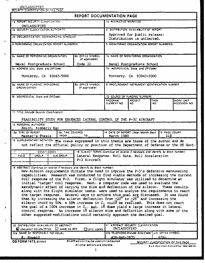
REPORT DOCUMENTATION PAGEIs REPORT SECUR-TY CLAss7rCATO. 1b RESTRICTIVE M&RKIN.GS
UNCLASSIFIED2& SECURITY CLASS:F•CATION ALJTHOR,TY 3 DISTRIBUTION 'AVAILABILITY OF REPORT2b DECLASSFCATtOP DOWNGRAD.NG SCHEDULE Approved for Public release;
Distribution is unlimited.
4 PERFORMING ORGANIZATION REPORT NUMBER(.) S MONITORING ORGANIZATION REPORT NUMBER(S)
61 NAME OF PERFORMWNG ORGANIZATION 6b OFF:CE SYMBOL 7a NAME OF MONIrORING ORGANIZATION
(it applicable)
Naval Postgraduate School Code 31 Naval Postgraduate School6c ADDRESS (City Stare and ZIP Cooe) 7b ADDRESS(Cty, State, and ZIPCode)
Monterey, CA 93943-5000 Monterey, CA 93943-5000
Bi NAME O; 9UNDiNG. SPONSORING 1b OFFICE SYMBOL 9 PROCUREMENT INSTRUMENT IDENTIFICATION NUMBERORGANIZATION (if applicable)
S' ADDRESS (City,. State, and ZIP Code) 10 SOURCE OF FUNDING NuMBERS
PROGRAM :PROJECT TASK WORK UNITELEMENT NO NO NO ACCESSION NO
11 TITLE (Include Stcurfit) ClaifficaVOn)
FEASIBILITY STUDY FOR EN11ANCED LATERAL CONTROL OF THE P-3C AIRCRAFT12 PERSONAL AUTHOR(S)
Smith, Kimberly Kay13& TYPE OF REPORT 3b TIME COVERED 14 DATE OF REPORT (Year. Mont., Day) PAGE COUNT
Master's Thesis I FROM M TO __ March 1989 , 11816 SUPPLEMENTARY NOTATION The views expressed in this thesis are those of the author and do
not reflect the official policy or position of the Department of Defense or the US Govt.
COSATi CODES 18 SUBJECT TERMS (Continue on reverse if necessary and identify by block number)FIELD GROuP SUB-GROUP Lateral Response, Roll Rate, Roll Acceleration
P-3 Aircraft
19 ABSTLACT (Con,,nue on teveje ,i nehsiary and idrtefy by block number)New mission requirements dictate the need to improve the P-3's defensive maneuveringcapabilities. Research was conducted to find viable methods of increasing the currentroll response of the P-3. First, a flight simulator was utilized to determine aninitial "target" roll response. Next, a computer code was used to evaluate theaerodynamic effect of varying the size and deflection of the aileron. These results,along with the flight simulator tests, were used to analyze the requirements to reachthe target response. Several ways to achieve this goal are discussed. It was foundthat by increasing the aileron deflection from +200 to +25 and increasinq theaileron chord by 50%, a 58% increase in C could be realized. This does riot reachthe goal of a 100% increase in C1, but, ii does yield a large increase in lateralcontrol response. An increase iý aileron size and deflection along with some of theother suggested modifications would certainly approach the desired goal.
20 DiSTRIBUTIONi AVAILABILITY OF ABSTRACT 2' AASTRACT SECURITY CLASSIFICATION
g] UNCLASSIEO'UNLIMIED 0 SAME AS RPT C DTIC USERS UNCLASSIFIED22& NAME OF RESPONSIBLE INDIVIDUAL 226 TELEPHONE (Include Area Code) I€C OFFICE SYMBOL
DD FORM 147 3, 84 MAR 83 APR ed-tion may be uied until eshouited SECURITY CL FICATION, OF THIS PAGEAll othe, editions O u S Oo,#'~*Ai lIAIIlg OafreO obso-l4e0-te.
i

Approved for public release; distribution is unlimited.
Feasibility Study forEnhanced Lateral Control
of the P-3C Aircraft
by
Kimberly Kay SmithB.S., University of Cincinnati, 1981
Submitted in partial fulfillment of therequirements for the degree of
MASTER OF SCIENCE IN AERONAUTICAL ENGINEERING
from the
NAVAL POSTGRADUATE SCHOOLMarch 1989
Author:Kimberlj Kay Smith
Approved by: C g. , 'ILCDR C. A. Heard, Thesis Advisor
R. M. Howard, Co-Advisor
•,v Dr. E. Roberts Wood, ChairmanDepartment of Aeronautics and Astronautics
Gordon E. SchacherDean of Science and Engineering
S~ii
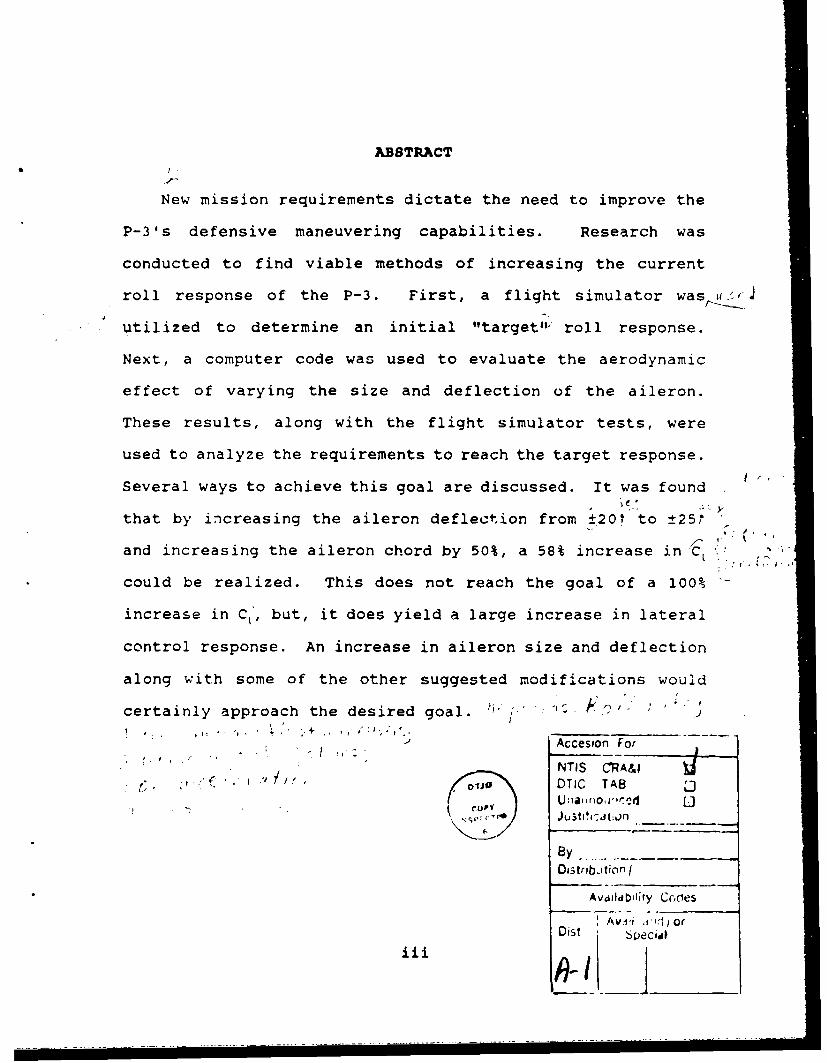
ABSTRACT
New mission requirements dictate the need to improve the
P-3's defensive maneuvering capabilities. Research was
conducted to find viable methods of increasing the current
roll response of the P-3. First, a flight simulator was uicJ
utilized to determine an initial "target",' roll response.
Next, a computer code was used to evaluate the aerodynamic
effect of varying the size and deflection of the aileron.
These results, along with the flight simulator tests, were
used to analyze the requirements to reach the target response.
Several ways to achieve this goal are discussed. It was found
that by increasing the aileron deflection from ±20t to ±250
and increasing the aileron chord by 50%, a 58% increase in CL
could be realized. This does not reach the goal of a 100%
increase in CL', but, it does yield a large increase in lateral
control response. An increase in aileron size and deflection
along with some of the other suggested modifications would
certainly approach the desired goal. , , , "1 ** : 1 - . ,,
Accesion For
NTIS CRA&I. -,* "o -DTIC TAB
U ,ar.O '.. U
ByOIitribJtion f
Avlldb'iily Codes
AvDi's l orDist Specidl
• ii"Ii iii _A __ iii

TABLE OF CONTENTS
I. INTRODUCTION . . . . . . . . . . . . . . . . . . . 1
A. BACKGROUND .............. .................. IB. PURPOSE ................... .................... 2C. DESCRIPTION OF THE P-3C AIRCRAFT ...... ....... 2D. METHOD OF EVALUATION ........ .... ............. 5
II. PRELIMINARY RESEARCH .............. ............... 7
A. F/A-18A AIRPLANE WITH ROLL RATE IMPROVEMENTSINCORPORATED ................ ................. 7
B. F-4S AIRPLANE LATERAL/DIRECTIONAL FLIGHT CONTROLSYSTEM MODIFICATION ......... .... .............. 9
C. PREVIOUS TESTS CONDUCTED ON THE P-3 AIRCRAFT 91. Removal of the Aileron/Rudder Interconnect
from the P-3B/C Aircraft ......... ........ 92. P-3 Flight Simulators ......... .......... 10
D. ANALYSIS OF RESEARCH .......... ............ 11
III. FLIGHT SIMULATOR TESTS ........ .............. 13
A. DESCRIPTION OF TEST EQUIPMENT ... ........ 141. Operational Flight Trainers (OFT) . . .. 142. Data Acquisition Equipment ... ........ 14
B. METHOD OF TEST ............ ................ 171. General Test Maneuvers ... .......... 172. Asymmetric Thrust ........ ............ 20
C. BASELINE CONFIGURATION ........ ............ 21D. LATERAL CONTROL FORCES ........ ............ 24E. MECHANICAL CHARACTERISTICS .... .......... 25F. EFFECTS OF CHANGING THE AILERON MOMENT
COEFFICIENT ............. .................. 261. Description of Test ...... ........... 262. Results ............ ................. 28
G. EFFECTS OF CHANGING THE TOTAL AILERONDEFLECTION .............. .................. 311. Description of Test ...... ........... 312. Results ............ ................. 33
H. EFFECTS OF USING FLAPS FOR ROLL ASSIST . . .. 371. Description of Test ...... ........... 372. Results ............ ................. 38
iv

IV. AIRFOIL CODE .............. ................... 41
A. DESCRIPTION OF AIRFOIL CODE. ... ........ .. 41B. MODIFICATIONS AND VERIFICATION .. ........ 42C. METHOD OF EVALUATION ........ ............. 43D . RESULTS................................................44
1. Effects of Varying the Aileron Size __ . 442. Effect of Varying the Aileron Deflection . 473. Effects of Varying the Angle of Attack . . 494. Combined Effect of Increased Aileron Size
and Deflection ......... .............. 52
V. CONCLUSIONS ............... ................... 55
VI. RECOMMENDATIONS ............. ................. 57
LIST OF REFERENCES ............... ................. 58
APPENDIX A TABLES .............. ................... 60
APPENDIX B PROGRAM LISTING: WINGIT ... ......... 72
APPENDIX C FIGURES (AIRFOIL CODE DATA SUMMARY) .... 75
INITIAL DISTRIBUTION LIST ............ ............... 110
v

ACKNOWLEDGEMENTS
I would like to thank Dr. Hank Smith, Lt. Boothe, Chief
Karl, Chief Rivers and Mr. Jim Stratten for all of their
assistance during the flight simulator tests at NAS Moffett.
And special thanks to Prof. Howard and LCDR Heard for their
help during all phases of this thesis.
vi
I. INTRODUCTION
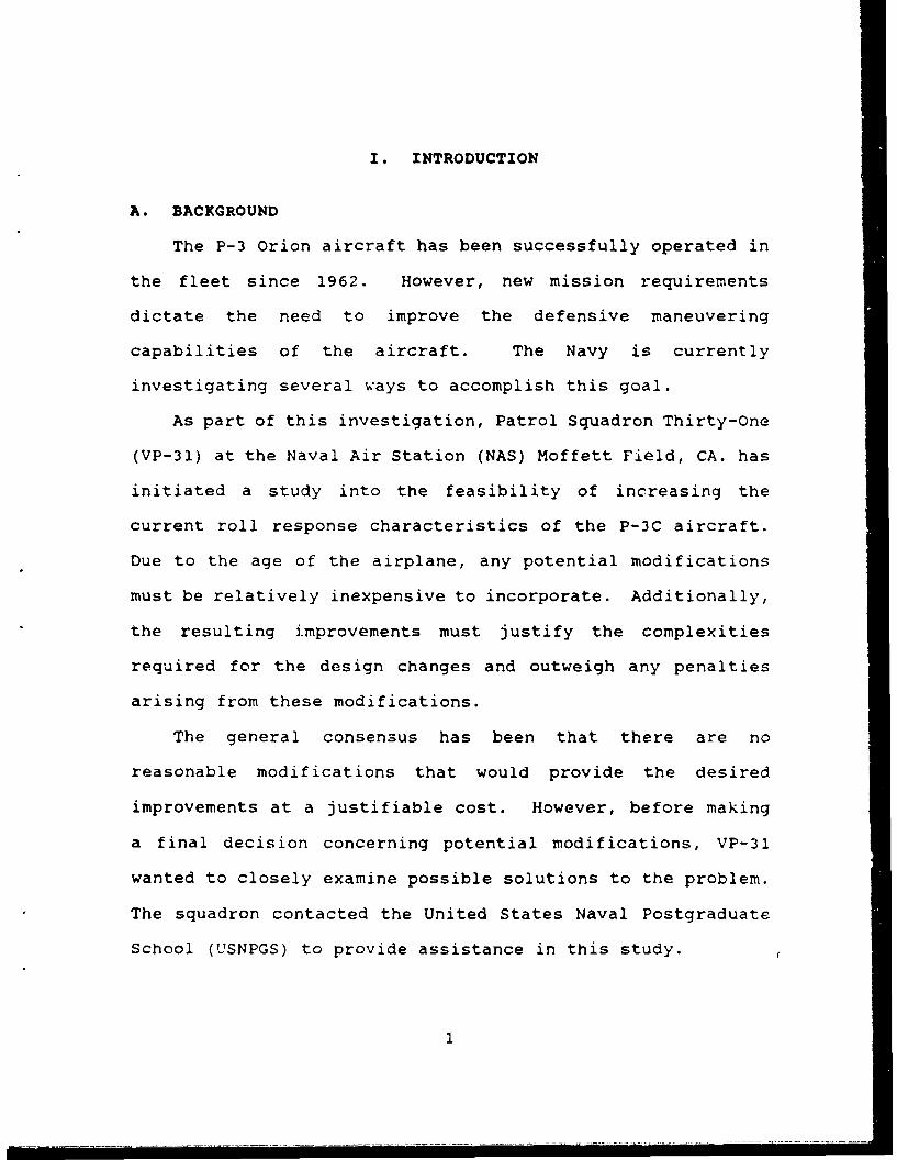
A. BACKGROUND
The P-3 Orion aircraft has been successfully operated in
the fleet since 1962. However, new mission requirements
dictate the need to improve the defensive maneuvering
capabilities of the aircraft. The Navy is currently
investigating several ways to accomplish this goal.
As part of this investigation, Patrol Squadron Thirty-One
(VP-31) at the Naval Air Station (NAS) Moffett Field, CA. has
initiated a study into the feasibility of increasing the
current roll response characteristics of the P-3C aircraft.
Due to the age of the airplane, any potential modifications
must be relatively inexpensive to incorporate. Additionally,
the resulting improvements must justify the complexities
required for the design changes and outweigh any penalties
arising from these modifications.
The general consensus has been that there are no
reasonable modifications that would provide the desired
improvements at a justifiable cost. However, before making
a final decision concerning potential modifications, VP-31
wanted to closely examine possible solutions to the problem.
The squadron contacted the United States Naval Postgraduate
School (USNPGS) to provide assistance in this study.
S. .. .. . .. . . .. • .. . . . . . . . .. . . . • . . .• .. . .. . . - . . . .. . .• . . . . . . . . . .• - . . . . " . . . . . . . .' . . . • . . . . . .. . .. . . .1.
B. PURPOSE
The purpose of this thesis was to provide assistance to
VP-31 in their efforts to enhance the defensive maneuvering
capability of the P-3 aircraft. Research was conducted to
determine viable methods of increasing the current roll
response characteristics of the P-3C aircraft. Each of these
methods was evaluated to predict the likely improvements that
could be realized. Due to the reasons stated above, several
obviously complex and expensive solutions, such as computer
operated systems and deflected engine thrust, were not
evaluated. However, once these options were disregarded,
complexity and expense were no longer considered to be factors
during this study.
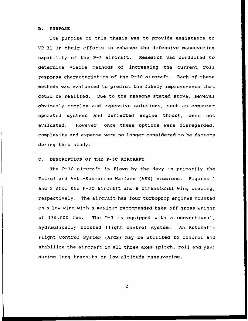
C. DESCRIPTION OF THE P-3C AIRCRAFT
The P-3C aircraft is flown by the Navy in primarily the
Patrol and Anti-Submarine Warfare (ASW) missions. Figures 1
and 2 show the P-3C aircraft and a dimensional wing drawing,
respectively. The aircraft has four turboprop engines mounted
on a low wing with a maximum recommended take-off gross weight
of 135,000 lbs. The P-3 is equipped with a conventional,
hydraulically boosted flight control system. An Automatic
Flight Control Syster (AFCS) may be utilized to con...rol and
stabilize the aircraft in all three axes (pitch, roll and yaw)
during long transits or low altitude maneuvering.
2

P-3C
Figure 1
P-3C Aircraft
3

0.O 0 0.0 2;.0 30'.0 40,0 50.0SPAN (rECT)
Figjure 2
Wing Planform of the P-3C Aircraft
Each of the control surfaces (aileron, rudder and
elevator) includes mechanically operated trim tabs.-
Additionally, high-lift Fowler flaps (illustrated in Figure
3) are incorporated inboard on the wings. The wing consists
of symmetrical NACA airfoils. At the root is the NACA 0014
airfoil; the wing sections narrow, linearly, to the NACA 0012
airfoil at the wingtip.
The current operating envelope of the aircraft prohibits
bank angles in excess of 65" for roll maneuvering and 70" for
coordinated turns. Additionally, the airframe is limited to
load factors between a negative 1 G and positive 3 G's for
most operational gross weights.
A complete description of the P-3C aircraft and operating
limitations can be found in Ref. 1. Detailed descriptions of
*4
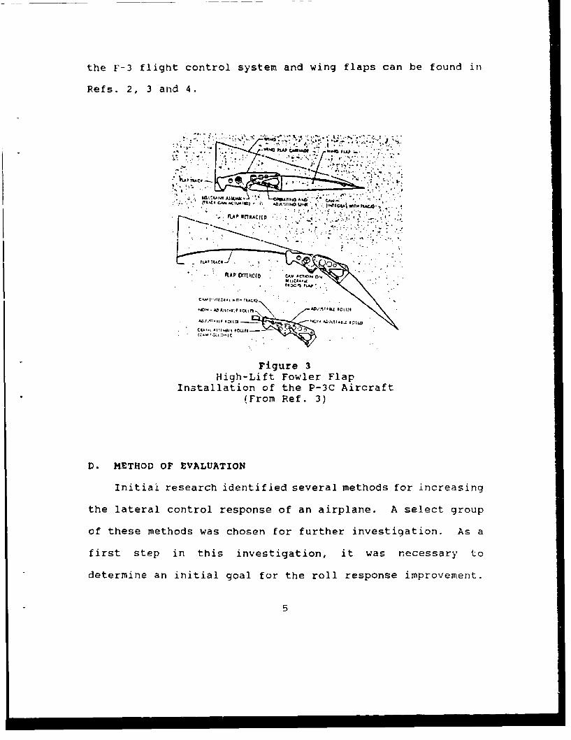
the F-3 flight control system and wing flaps can be found in
Refs. 2, 3 and 4.
40 f" '.L-1 ZsPL
* iLAAPl.Ie..ACOto
K Al D MNt C " ACV01 0
- FLA'TACS J..
Cooo
HighLif Fowler Flap
(FiguRef 3)
D. METHOD OF EVALUATION
Initial research identified several methods for increasing
the lateral control response of an airplane. A select group
of these methods was chosen for further investigation. As a
first step in this investigation, it was necessary to
determine an initial goal for the roll response improvement.
5

A flight simulator was utilized to qualitatively determine
this "target" roll response increase and to quantify the
resulting lateral characteristics. After the initial "target"
response was determined, a computer airfoil code was used to
evaluate the aerodynamic effect of airfoil sections with
various sizes and deflections of the trailing edge control
surfaces. These airfoil sections were then mathematically
combined to determine the rolling moment coefficients for a
variety of wing configurations. These results, in conjunction
with the flight simulator tests, were used to analyze the
modifications required to reach the desired lateral response.
Throughout this evaluation, several factors were not
investigated, even though they are obviously important in the
consideration of increased lateral response. The primary
factor that was neglected was structural integrity. Neither
the structural impact of any modifications to be made to the
aircraft, nor the effect of the increased structural loads on
the airframe due to the more aggressive maneuvering, were
evaluated. Other less critical factors that were not
considered will be discussed as appropriate.
6
II. PRELIMINARY RESEARCH
Literature research was conducted to determine what
modifications, if any, had been made to other transport type
aircraft to increase its roll rate or roll acceleration.
Additionally, current technology design standards were
investigated to discover the options available 4 1 the area of
lateral control response.
Research revealed no historical data on increasing the
roll response of a transport type aircraft. There were,
however, two reports on increasing the lateral response
characteristics of fighter type aircraft. Although the
mission for fighter aircraft is much different than that for
the P-3, the modifications and results proved to be very
informative. These reports will be discussed as well as the
results from some previous P-3 flight tests. Finally, The
impact of these reports on the P-3 study will also be
discussed.
A. F/A-18A AIRPLANE WITH ROLL RATE IMPROVEMENTS INCORPORATED
Reference 5 discusses tests conducted by the Navy at the
Naval Air Test Center (NATC), to evaluate the roll rate
improvements incorporated in the F/A-18A Aircraft. According
to the findings of the report, the F/A-18A aircraft had
exhibited serious problems with inadequate roll performance.
McDonnell Aircraft Company incorporated several major hardware
7

changes to improve the lateral performance characteristics of
the aircraft. These changes included:
1. An increase in aileron size by extending the aileron
surface to the wingtip.
2. Modifications to the wing structure designed to
increase the wing stiffness.
3. Trailing edge flaps were moved aft 1.5 in. at zero
deflection to allow for increased flap range from 8" trailing
edge up (TEU) to 45" trailing edge down (TED). These values
were previously 0" TEU to 45" TED. This change allows for
±16" of L fferential trailing edge flaps during rolls.
4. An increase in differential tail deflection authority
from t20* to ±26".
5. In addition to the hardware changes, many software
modifications were necessitated by the various roll rate
improvements. These changes will not be discussed since they
are not applicable to the P-3.
The test results showed that the maximum steady state roll
rates and time-to-bank to 90' were significantly improved
throughout most of the flight envelope that was investigated.
However, the resulting characteristics were still not adequate
for the requirements of the present day fighter aircraft.
8

B. F-4S AIRPLANE LATERAL/DIRECTIONAL FLIGHT CONTROL SYSTEM
MODIFICATION
Reference 6 discusses tests conducted by NATC to evaluate
the modifications to the lateral/directional flight control
system (Roll Mod) of the F-4S aircraft. According to this
report, the F-4S exhibited sluggish lateral characteristics
in the power approach (PA) configuration due to the
installation of leading edge slats. Several modifications
were incorporated into the roll and yaw axes of the AFCS.
These changes included:
1. Addition of a roll rate gyro feedback signal to the
rudder series servo.
2. Reduction of the yaw rate gyro feedback signal to the
rudder series servo.
3. Addition of a roll stick gain to lateral series servo.
The tests results indicated that the incorporation of the
Roll Mod in the F-4S airplane improved lateral control.
C. PREVIOUS TESTS CONDUCTED ON THE P-3 AIRCRAFT
1. Removal of the Aileron/Rudder Interconnect from the
P-3B/C Aircraft
Reference 7 discusses tests conducted by NATC to
determine the effect of removing the aileron/rudder
interconnect (ARI) from the P-3 aircraft. The following is
a summary of this report.
9
An ARI is included as part of the lateral control
system of the P-3 aircraft. The primary purpose of the ARI
is to improve aileron control wheel centering and to reduce
the rudder force required in shallow turns by means of a
spring in an interconnection cartridge. Because of numerous
instances of aileron/rudder control binding and jamming
associated with the ARI, the Navy was considering removing the
ARI.
An evaluation of the P-3 was cunducted to determine if
the removal of the ARI resulted in a change to the lateral
flying qualities. According to the report, none of the four
test pilots involved in the testing was able to perceive a
change in the lateral-directional flying qualities throughout
the qualitative phase of tests. It was concluded that the
removal of the ARI had no significant effect on the lateral
control effectiveness of the P-3 airplane during mission
tasks.
2. P-3 Flight Simulators
Reference 8 discusses previous testing conducted to
verify the flight fidelity characteristics of the P-3 Flight
Simulators that were used for this investigation. This report
was used extensively for comparison between the original data
and results from this evaluation and will be discussed as
appropriate. The report includes both simulator and actual
aircraft test data.
10

D. ANALYSIS OF RESEARCH
Several of the modifications that were made to the fighter
aircraft could certainly be considered for the P-3,
particularly in the area of aileron sizing and flight control
modifications. The modifinations were not sufficient enough
to create a tactical fighter. However, the desired purpose
for the P-3 lateral respon6 improvements is to enhance the
defensive maneuvering capabilities of the aircraft. Although
the idea of taking advantage of the ARI initially appeared to
be a plausible option, the previous tests show that this is
not the case.
There are several other options to increase the lateral
response in addition to those previously discussed. Those
that were evaluated will be discussed as appropriate. Some
methods that were not evaluated but appear viable include the
addition of stall fences and spoilers. Although no background
information has been found, it was learned from a retired Navy
pilot that the addition of stall fences produced a significant
improvement in the lateral response of the S-2 aircraft
several years ago.
Spoilers have been tried and proven as roll generating
devices. Although spoilers were not evaluated directly, the
results encountered during rolling moment coefficient tests
(discussed later) can be applied to spoilers as well as to
other lateral control surfaces. As with ailerons, spoilers
increase the rolling moment of the wing. It is recommended
11

that further evaluation be conducted to determine the effect
of both stall fences and spoilers.
12

III. FLIGHT SIMULATOR TESTS
A significant increase in roll rate and acceleration is
desired for defensive maneuvering. However, more sensitive
lateral control can lead to the degradation of many of the
other mission requirements of the P-3. Anticipated problems
include an increase in the workload as well as a decrease in
the accuracy while performing `-he precise heading and lineup
changes required during approaches and operational ASW
maneuvers.
Two P-3 flight simulators were utilized to provide a
quantitative investigation of various changes which might
increase the lateral response of the aircraft. Throughout the
tests, all changes were qualitatively evaluated with respect
to aircraft response and pilot workload. This investigation
permitted determination of an initial "target" roll response,
representing a realistic compromise between the increased roll
rate and the resulting higher pilot workload. The changes to
be investigated were simulated by modifying various portions
of the simulator software. These software modifications will
be described as they are discussed in the report. During the
tests, software modifications were incorporated by the flight
lead engineer of the Link Tactical Military Simulation Corp.
Only one modification was evaluated at a time to determine the
effect of each individual change. Obviously, a combination
13

of these charges could be used to create larger rolling
moments.
Nine hours of tests were conducted during two separate
simulator periods. Two Navy F-3 pilots performed different
mission maneuvers and test inputs for each of the lateral axis
changes.
A. DESCRIPTION OF TEST EQUIPMENT
1. Operational Flight Trainers (OFT)
The simulators used were Device 2F87(F) OFT Nos. two
and three, operated by COMPATWINGSPAC at NAS Moffett Field,
CA. Each of the OFT's incorporates a P-3C flight compartment
facsimile, mounted on a six-degree-of-freedom motion base.
The flight compartment includes an instructor station, pilot
and engineer stations, and additional seats for observers.
The flight compartment arrangement is illustrated in Figure
4. A computer generated visual display system is mounted on
the flight compartment and was used to provide the necessary
visual cues to the pilots throughout testing. A detailed
description of the OFT's can be found in Ref. 9.
2. Data Acquisition Equipment
The amount of time available to conduct the tests was
limited because of the operational status of the flight
simulators. This limitation restricted the scope of these
tests and precluded elaborate instrumentation. Most of the
data was obtained using hand-held stopwatches and was recorded
14

( W FII I .J .. . _. l
Figure 4P-3C Operational Flight TrainerFlight Compartment Arrangement
(From Ref. 9)
manually. Add tionally, included as part of the instructor's
station were two Cathode Ray Tubes (CRT's) which provided
continually updated information about the instantaneous flight
condition of the trainer. The flight conditions page proved
to be especially helpful during steady state conditions. A
sample copy is shown in Table I. Hard copies of this page
were easily made, but required excessive time to print.
Initially, several hard copies of each maneuver were printed
to provide a rough time history. However, this procedure
became too time consuming. Therefore, during the latter
15
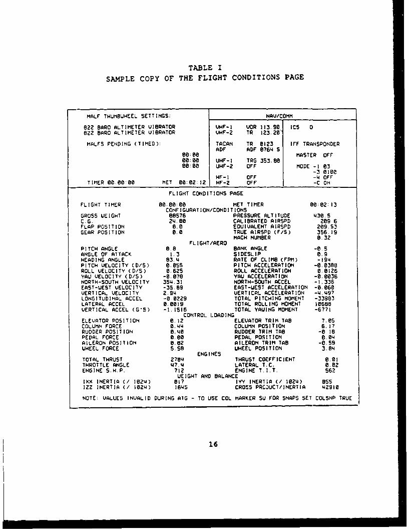
TABLE I
SAMPLE COPY OF THE FLIGHT CONDITIONS PAGE
HALF THUMBWHEEL SETTINGS: NAV/COMM
822 BARO ALTIMETER VIBRATOR VHF-I VOR 113.90 ICS 0822 BAR0 ALTIMETER VIBRATOR VHF-Z TR I23.2e"
MALFS PENDING (TIMED): TACAN TR 0I23 IFF TRANSPONDERADF ADF 0764 5
00:e MASTER OFF08:08 UHF-I TRG 353.8800:08 UHF-2 OFF MODE -1 03
-3 0100HF-I OFF -4 OFF
TIMER 00 00808 MET 00:02:12 HF-2 OFF -C ON
FLIGHT CONDITIONS PAGE
FLIGHT TIMER 0:008:00 MET TIMER 00:02:13CONFIGURATION/CONDITIONS
GROSS UEIGHT 88576 PRESSURE ALTITUDE 438.5C.G. 214.80 CALIBRATED AIRSPD 209 6FLAP POSITION 0.0 EQUIVALENT AIRSPD 209.53GEAR POSITION 0.0 TRUE AIRSPD (F/S) 356.19
MACH NUMBER 0.32FL IGHT/AEROPITCH ANGLE 0.8 BANK ANGLE -0 SANGLE OF ATTACK 1.3 SIDESLIP 0.9HEADING ANGLE 83.4 RATE OF CLIMB (FPM) -194PITCH VELOCITY (D/S) 0.05S PITCH ACCELERATION -0.0388ROLL VELOCITY (D/S) 0.625 ROLL ACCELERATION 0.0126YAW VELOCITY (D/S) -8.078 YAU ACCELERATION -0.0036NORTH-SOUTH VELOCITY 3514.31 NORTH-SOUTH ACCEL -1.336EAST-WEST VELOCITY -35.89 EAST-WEST ACCELERATION -0.060VERTICAL VELOCITY 2.914 VERTICAL ACCELERATION -4.497LONGITUDINAL. ACCEL -0 0229 TOTAL PITCHING MOMENT -33983LATERAL ACCEL 0.0019 TOTAL ROLLING MOMENT 10688VERTICAL ACCEL (G'S) -1.1516 TOTAL YAWING MOMENT -6771
CONTROL LOADING
ELEVATOR POSITION 0.12 ELEVATOR TRIM TAB 7.05COLUMN FORCE 0. 44 COLUMN POSITION 6.17RUDDER POSITION 0.48 RUDDER TRIM TAB -0 18PEDAL FORCE 0.00 PEDAL POSITION 0.04AILERON POSITION 0.0z AILERON TRIM TAB -0.59WHEEL FORCE S.s8 UHEEL POSITION 3.84
ENGINES
TOTAL THRUST 27814 THRUST COEFFICIENT 0.801THROTTLE ANGLE 47.4 LATERAL T.C. 0.02ENGINE S.H.P. 712 ENGINE T.I.T. 562
UEIGHT AND BALANCEIXX INERTIA (1 202w) 817 IYY INERTIA (/ 1024) 8ssIZZ INERTIA (/ 10214) 1645 CROSS PRCZUCT/INERTIA 429 10
NOTE: VALUES INVALID DURING AIG - TO USE COL MARKER SU FOR SNAPS SET COLSNP TRUE
16

phases of the data collection, hard copies were printed for
only the steady state condition maneuvers.
In addition to the flight compartment, the simulator
hardware consists of digital computers, interface equipment
and associated electronics equipment required to simulate the
aircraft. As part of this equipment, there is an interactive
ccmputer which was used to make the software changes during
the tests. This allowed for quick modifications with minimum
stop time and significant flexibility throughout testing.
B. METHOD OF TEST
I. General Test Maneuvers
The roll response testing was conducted in accordance
with procedures in the USNTPS Fixed Wing Stability and Control
Flight Test Manual (Ref. 10). The roll rate and acceleration
for each of the software changes, as well as a baseline
condition (the unmodified simulator), were evaluated in two
ways. First, the aircraft was established in a straight and
level static flight condition. A full lateral step input wax
applied to the control yoke while maintaining altitude and
power setting. A stopwatch was used to determine the elapsed
time from 0° to 60" angle of bank. Although this does not
correspond to a steady state roll rate, it does present a
consistent quantitative methcd for comparison between the
various simulated conditions. This maneuver was performed in
both the left and right directions.
17

The next maneuver was initiated from a steady, level
60' angle of bank turn. A full lateral control step input was
then applied, to the control yoke, in the opposite direction
while maintaining altitude and power setting. A stopwatch was
used to determine the elapsed time from 60° to 50', and from
0' to 60' in the opposite direction. Although not a precise
indicator of roll acceleration, the time to roll through the
initial 100 does provide a consistent quantitative method for
comparing roll acceleration between the different simulated
conditions. It was found that the aircraft had reached a
steady state roll rate when passing through 0* angle of bank.
Therefore, the time to roll thrcugh the final 60' provided a
relatively accurate value of the steady state roli rate. The
flight conditions page was used to verify the computed steady
state values. The tests and test conditions that were
conducted are summarized in Appendix A, Table I. A tabulated
summary of the results from the stopwatch measurements and
flight conditions pages is shown in Appendix A, Table II.
Definitions of the maneuver descriptions and simulator
conditions used throughout this report are shown in Tables II
and III respectively. All tests were conducted at a gross
weight of approximately 92,000 lb. with a CG of about 24.5%
Mean Aerodynamic Chord (MAC). The landing gear and flaps were
up except where required for approaches, landings and take-
offs, as well as for the split-flap evaluation. Neither the
flight conditions page, nor stop watch times, were obtained
18

TABLE IIMANEUVER DESCRIPTIONS
0 TO 60 INDICATE ROLLS INITIATED FROM EITHER LEVEL FLIGHT ORand A STEADY 60 DEG BANK IN THE RIGHT O LEFT DIRECTIONS
60 TO 60 AS INDICATED (THROUGHOUT THE REPORT, VALUES LESSTHAN 0 REPRESENT MANEOVERS TO THE LEFT)
HEADING QUALITATIVE EVALUATION OF PRECISE HEADING ANDCHANGES LINEUP CHANGES
APPROACHTAKE OFF QUALITATIVE EVALUATION OF VARIOUS MISSION MANEUVERSLAND I NG
ASYMMETRIC INITIATING A ROLL BY RETARDING ONE OUTBOARD ENGINETHRUST
30 DEG CCW INDICATES A 30 OR 90 DEG CLOCKWISE OR COUNTERand CLOCKWISE CONTROL INPUT AS IN~DICATED90 DEG CW
(SEE TEXT FOR DETAILED DESCRIPTIONS)
TABLE IIISIMULATOR CONDITIONS
BASELINE THE BASIC SIMULATOR WITH NO SOFTWARE MODIFICATIONS
K - .99,1.5, MODIFIED VALUE OF THE TOTAL AILERON ROLLING1.75 or 1.99 MOMENT COEFFICIENT
4 OR 8 DEG AN INCREASED AILERON DEFLECTION OF 4 OR 8 DEGDEFLECTION ON BOTH AILERONS, IN BOTH UP AND DOWN DIRECTIONS
SPLIT-FLAP UTILIZING THE SPLIT-FLAP CONDITION
(SEE TEXT FOR DETAILED DESCRIPTIONS)
19

for all runs, which accounts for the lack of data in some
areas.
Throughout the quantitative data acquisition phase,
the pilots qualitatively evaluated the aircraft for
controllability and workload. Although Handling Quality
Ratings (HQR's) were not assigned, the various modified
configurations were qualitatively compared to determine the
optimum condition. In addition to the "canned" maneuvers, the
pilots performed approaches, as well as precise heading and
lineup changes, to determine the potential mission degradation
that would occur during typical mission maneuvers.
2. Asymmetric Thrust
Another method of test that was brifly attempted was
the utilization of asymmetric thrust to initiate a roll. Each
of the four turboprop engine produces 4600 shaft horsepower
(maximum rated). Any thrust differential that might occur
between the two outboard engines would provide an unbalanced
directional force due to the large lateral separation,
resulting in a lateral force due to the dihedral effect.
Additionally, since the propeller effect or the airflow over
the wing produces a considerable amount of lift, a large lift
differential will occur between the two wings, producing a
larger rolling moment.
Several attempts were made to take advantage of this
asymmetric thrust. Rolls were initiated from a straight and
level conditiin by advancing one outboard throttle and
20

retarding the other. This method of roll initiation did, in
fact, create a significant roll rate. However, there were two
problems experienced during this maneuver. First, the pilot
workload was unacceptable. A reduction in workload would be
cea.-*zed if the copilot operated the throttles while the pilot
controlled the aircraft. However, an unacceptable amount of
crew coordination would be required and the throttle inputs
and subsequent rolling moments would be delayed. A second
problem existed in the large amount of altitude lost while
performing this maneuver. Since the majority of the P-3
mission is spent low, over the water, altitude loss can be
very dangerous. The difficulties associated with the use of
asymmetric thrust for enhanced roll acceleration precludes
this option from consideration.
C. BASELINZ CONFIGURATION
A complete series of tests was conducted prior to
modifying the simulator software in order to obtain baseline
data. This data was used to evaluate the changes to the
lateral response due to each of the software changes. Also,
this ba:.line data was u3ed for comparison with results from
previcus OFT tests, Ref 8. The results are tabulated in Table
I'l, and graphically displayed in Figure 5. As can be seen in
the figure, the baseline simulator exhibited roll rates of
approximately 20"/sec. throughout the airspeed range tested.
This data agrees well with Ref. 8. The differences seen
21

is'%a v W 4w N f i m0 a 4 % - N 0
---- --- ---- N- -
f- ev in 00
q0 w WqW a ft ftN
-n W0 el eo e f- % F0
N' eii ftlON ~ C
II I II
N~~% Wis ft I'N a -a~ ~ NN0IA 0 f N-
.3 W 0 l 0 i s O0 lW
f-f b, en O f N is " ' '
en z %0 v'0 00
-- ~ ~ ~ I ."A N 'aU% W
of.a 1. " 11 1%N& : O l'V N
isV W . ... i
0 0 0- 0 0a*0 a 0 00 00 0 0 0 O a
04 0 Go a I" w
F-- r 0a b, 0-.f f .F P. O f-g -f 0"0 to f-CC Av tv msV f-%i Nis m
NO 'Sn mC N in %isW -y Owi z tvi fw
-- N III Ow NiOsOwO
'a 'a ' I* -V b, fn 'a ' aa ' aa m 'a 'aA
22000

C) MANEUVER:ROLL 60 DEG TO 60 DEG
3-0 - LEFT
"G - -C - RIGHT ..........
06-6
0 260 2A0 -36o0 A•o 4;oAIRSPEED (KCAS)
A) MANEUVER: B) MANEUVER:0 TO 60 DEG ROLL B) 60 DEG TO 60 DEG
560%
0
194- 002 ~ ~ 40-
FIGURE 5Baseline Configuration
23
between the left and right directions are due to the
slipstream effects of the airflow over the wing caused by the
turning propellers as well as the torque effects.
The 30" CCW and 90" CW maneuvers were duplicated from Ref.
8. For a 30* CCW input, the steady state roll rate was
7.7"/sec for the airplane and 11*/sec for OFT 2, compared to
an average of 8.7°/sec for these tests. For a 90 CW input,
the steady state roll rate was 21.6"/sec for the airplane and
18"/sec for OFT 2, compared to an average of 24.5'/sec for
these tests. The results are not exact, but are acceptable
for the purpose of this evaluation, since the major concern
is the amount of improvement obtainable, and not the precise
values of the results.
D. LATERAL CONTROL FORCES
Throughout the evaluation, the lateral control forces were
excessive. Forces in excess of 50 lbs. (often as high as 70
lbs.) were required to establish full lateral control inputs.
These high forces were noted for turns in either direction,
over the full airspeed range tested and for all of the
modifications to the simulator. These control forces resulted
in slow inputs and eventual pilot fatigue. Slow inputs result
in inadequate roil acceleration. Although the steady state
roll rate will not be affected by this low roll acceleration,
the initial aircraft response will be sluggish. A reduction
24

in control forces would permit quicker inputs, resulting in
increased roll acceleration for more aggressive maneuvering.
The control forces existing on the OFT's could not be
changed. Therefore, the actual amount of reduction in control
forces needed for the desired effect is not evident. However,
it is obvious that any decrease in the lateral control forces
would result in an improvement to the current roll response
characteristics of the P-3. However, it should be noted that
the lateral control forces exhibited by the flight simulator
are somewhat greater than those of the actual P-3c aircraft.
E. MECHANICAL CHARACTERISTICS
The current lateral flight control system of the P-3
consists of a group of cables operating between the control
wheel and an aileron booster unit. The movement is then
transmitted to the ailerons via push-pull rods connecting to
the aileron bellcrank assemblies. An inherent drawback with
this type of system is a delay in transmitting control
movement to the control surfaces, as well as the slow movement
of the control surfaces. Therefore, it takes a relatively
long time for the aileron to move through the full deflection
range. Although step inputs were utilized to initiate all
roll maneuvers, the inherent delay in transmitting the control
movements to the ailerons and slow reaction time of the
surfaces resulted in sluggish aircraft response. The precise
time between control input and completion of control movement
25

was not documented, but results indicated that almost five
seconds was required. This time delay is not conducive to a
"snappy" roll.
Altering the mechanical control system of the aircraft in
such a way that would reduce the transmission delay and
increase the rate of movement of the aileron would contribute
to an increased lateral control response. This would allow
for quicker aircraft response to pilot input. As with the
control forces, there was no way to evaluate this type of
change on the flight simulator. Therefore, the extent of
control system modifications required to create the desired
response is not known. However, advances in technology since
the initial installation of this system into the P-3 make it
a viable option. It is recommended that further evaluation
be conducted to determine the possible results of such a
modification.
F. EFFECTS OF CHANGING THE AILERON MOMENT COEFFICIENT
I. Description of Test
The first software modification to the simulator,
involved a systematic increase in the total rolling moment
coefficient (Cd). Evaluations of the different C•'s were
conducted utilizing the simulator. The changes to the
software simulated a number of possible modifications to the
actual airframe which would result in a larger contribution
of the lateral contrcl surfaces to the rolling moment of the
26
aircraft. Such changes could include a larger aileron or the
addition of other control surfaces such as spoilers.
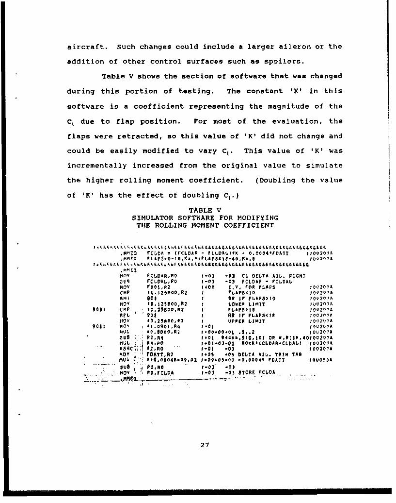
Table V shows the section of software that was changed
during this portion of testing. The constant 'K' in this
software is a coefficient representing the magnitude of the
C, due to flap position. For most of the evaluation, the
flaps were retracted, so this value of 'K' did not change and
could be easily modified to vary C,. This value of 'K' was
incrementally increased from the original value to simulate
the higher rolling moment coefficient. (Doubling the value
of IK' has the effect of doubling C,.)
TABLE VSIMULATOR SOFTWARE FOR MODIFYING
THE POLLING MOMENT COEFFICIENT
.NMe rCLOA r (FCLOAR - ILLDAU)*K - O.0041FoArT J0U0027L.MPmo FLApS=o-I0,Km.u' rLAPSfz1-40,Ke.8 100207A
I 5..&f.b&1• 5f&bA.5..&.'k ELG&&.5.&&&&8t3&&.&&5.&b5.&L5&& 5.&5.5.I,.5.5&&&E&
.MM Eelt1Ov FCLCAR,WO 1-03 -03 CL DELTA AlL. FIGHT50 FCLDAL,R0 1-03 -03 FCLDAR - rCLDALHOV rOOl,A2 1400 J.V. FOR rLAPS iou207ACMP 10.125800,R2 1 rbAPSCIO 10V207ABMI 80$ 1 BR ir FbAP.S'1O 10 V2 0AHoy 00.1230OO,R2 I LOWER LIMIT U02077A
80i (:P f0.25600,R2 I rLAPS)33 IOU207AArt 90$ 1 RR Ir FLAPS<II o00107A14OV 10,25e00,R2 I UPPER LIMIT 1Q•1U7A
90$1 R0"- 01.0801,R4 1401 JOU207AMIL 0.8o00OR2 1+00+0+O0L .1,.2 I0U207ASUB R2,R4 1#01 04CK2,90,10) OR s.{(10,40100207A
U i, R4,PO :+01- 0 3 -01 R0K*(CLDAR-CLDAL) 100207A- SH¢•:',! #2,RO " -0i -03 tO0207A
MOY "DATT,R2 1.05 +05 DELTA AIL. TRIM TABftIJL 1" + O.00049-09,P2 1-094o-03-0 -0.0004* rDATI o1o053A
3US 02,Ro1-03' -03. . MOV RoI'CLDA .1-03 -03 8TORE rCLDA
27
For each value of 'K', the described series of
maneuvers was conducted to determine the resulting roll rate
and acceleration, while the effect on the flying qualities of
the airplane was qualitatively evaluated.
2. Results
A tabulated summary of the results of this test is
shown in Appendix A, Table III. These times are graphically
displayed in Figures 6 and 7, for the left and right
directions respectively. The baseline condition is included
for comparison.
As expected, an increase in the value of 'K' generally
resulted in enhanced roll response. The pilots found that a
value of 'K' = 1.99 provided an uncontrollable flight regime.
The aircraft was too responsive, resulting in constant over-
correction by the pilots and hence the inability to maintain
a wings level flight condition. At this value of 'K', the
time to roll the initial 10° and the steady state roll rate
do not appear to be consistent with the trends established by
the other values of 'K'. However, this condition is not
considered to be as quantitatively accurate as the others
because the pilots anticipated overshooting 70" angle of bank
(resulting in a crash condition on the simulator). Therefore,
the control inputs were removed prematurely, decreasing the
roll response.
Qualitatively, as the value of 'K' was increased from
the original value, the aircraft became more sensitive in the
28

ROL. 60 DEC R TC 6C ..
"a 0r-> -•( "• c.": -
2C ,IM
.- - K = ,_,5-0 -: lr" ,
5- C= C
-C .
=c
5 210 25t 3C-3s 2ýc 4L,AIRSPEED (AS'
ROL 63 DEG CR- T" E--
U 2
"2- -3 -5 2
- -- 'Z-
A *Sý:'E: S,,,A AIRS'EED_ (K :AS'
53.-0-^' -... '^, -- , -• ,- 0
,,_ e o . Terr-12r
29)

C) &VANEUVER:ROLL 60 DEC LT TO 6.0 DEC RT
- BASELNE-
> - K =0.99 D
-K =1.50
-K 1.7.5
-K =1.099
150 200 250 300 350 400AIRSPEED (KCAS'j
A' VANEUV-R: B) VANEUVER:C TO 60 -:)-C FROL RCH ROLL 60 DEC LT TO 60 DECG RT
5- -
00
-~ a~ j <> ~
00
W 00
lateral axis. A value of 'K' = 1.75 provided a controllable
aircraft, without an unreasonable increase in workload, and
exhibited excellent lateral flying qualities. The steady
state roll rate was found to be about 35"/sec. (dependent on
airspeed). The roll rate was approximately 75% higher than
the baseline condition for all airspeeds tested. Although
there was a tendency to slightly over control the aircraft at
60" angle of bank, an approach to landing was safely performed
with no lineup problems. In general, the pilots quickly
adapted to the increased roll response. As described by one
pilot: "It's like driving a car with power steering for the
first time - you tend to over control it initially, but you
get used to it quickly."
A value of 'K' = 1.75 represents an increase in the
total aileron rolling moment coefficient of 194% for the
normal flap (0°) condition and an increase of 219% in the
approach flap (18') condition. Therefore, doubling the
current aileron rolling moment coefficient of the P-3 appears
to be an ideal goal for changes to the P-3 lateral axis.
G. EFFECTS OF CHANGING THE TOTAL AILERON DEFLECTION
1. Description of Test
The second software modification was an increase in
the total aileron deflection of the simulator. The software
was modified in such a way as to provide increased total
deflection on the left and right ailerons, as well as larger
31
i i- -
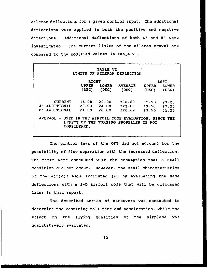
aileron deflections for a given control input. The additional
deflections were applied in both the positive and negative
directions. Additional deflections of both 4" and 8' were
investigated. The current limits of the aileron travel are
compared to the modified values in Table VI.
TABLE VILIMITS OF AILERON DEFLECTION
RIGHT LEFTUPPER LOWER AVERAGE UPPER LOWER(DEG) (DEG) (DEG) (DEG) (DEG)
CURRENT 16.00 20.00 ±18.69 15.50 23.254" ADDITIONAL 20.00 24.00 ±22.69 19.50 27.258" ADDITIONAL 24.00 28.00 ±26.69 23.50 31.25
AVERAGE - USED IN THE AIRFOIL CODE EVALUATION, SINCE THEEFFECT OF THE TURNING PROPELLER IS NOTCONSIDERED.
The control laws of the OFT did not account for the
possibility of flow separation with the increased deflection.
The tests were conducted with the assumption that a stall
condition did not occur. However, the stall characteristics
of the airfoil were accounted for by evaluating the same
deflections with a 2-D airfoil code that will be discussed
later in this report.
The described series of maneuvers was conducted to
determine the resulting roll rate and acceleration, while the
effect on the flying qualities of the airplane was
qualitatively evaluated.
32

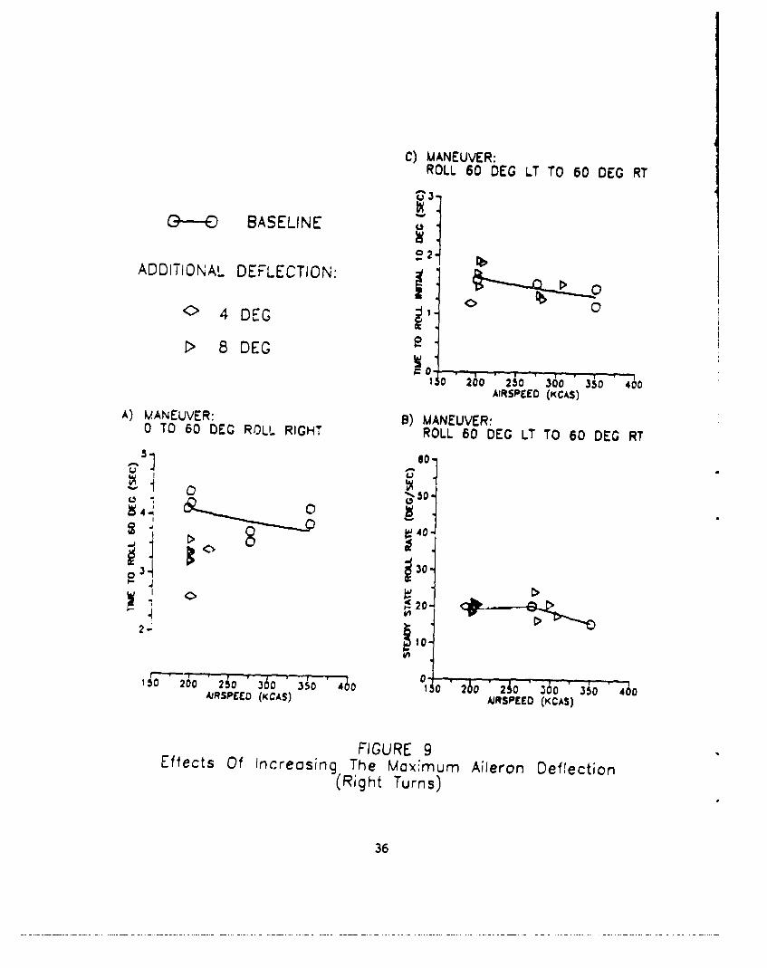
2. Results
A tabulated summary of the results of this test is
shown in Table VII. The average values are included because
the effect of the turning propellers were not considered
during the later evaluation with an airfoil code. These
values will be used for comparison with those results. A
graphical representation of these results compared to the
baseline air:raft is shown in Figures 8 and 9 for left and
right turns respectively. As can be seen, the additional
deflection does, indeed, increase the steady state roll rate
of the P-3 by as much as 50%, without unreasonably increasing
the workload.
Restrictions within the OFT hardware, limited the
total increase in aileron deflection to 16* on each side.
This yielded an increased deflection of a positive 8' on one
side and a negative 8° on the opposite side for a full control
input. This maximum increase in deflection is not considered
to be the limiting case as far as lateral response or pilot
workload is concerned. However, the effects of the local flow
separation must still be considered.
33

-~~0 0. M ' N 0 ,0~
W -32
a'L. N ~ 0 N N .2N% .4 -I
- -0 -
a, .- a- 0 %P 0 , m N V , m ' r D 0 wa !C
WO.. 0 40~ 0o r-D-0~ 0
- %D I NO -I %P r I I
01 .- 10 .g w ý
o %P 0 00w % ý
10 r , 0 0 w'-.I 0 0 ~
w Hr 0 00 N 0 N r. In 0 N ww 0 0 cc %D Oa 00 ww w n00
It C 0N w N w0 0 '0
H 2Z. N N N N .N, - N ~ N
C! 7. . . .h Z e .I,.' ~N 0'0 '~-N~&
o: 0. 1-~ 1.-. ! N 00 0 N 0! 0V
-zc
LL:
U: 000 O~000-00 00000000000000
0000 t- 0 Q0 0 0 a000 0 a0 0 0 0001l'''1
( ~ o -0 N0000000000v000 0'00'0'
0 00C 0 % '0 w wW W W WW W W '
tc C, 0 rfl &0 0 00 00 00 0 0 00000w
Ic N.' r ¶ N N N
34

C) MANEUVER:
ROLL 60 DEC RT TO 60 DEG LT
---- BASELINE
ADD:TIONAL DEFLECTION: _2
> 8 DEG
1.90 200 2i0 360 35;0 400MHSPEEC (KCAS)
A) VANEUVER: B) MANEUVER:0 TO 60 DEG ROLL LEFT ROLL 60 DEG RT TO 60 DEG LT
580
450-
•44
~30-
~20900
3•IJ 10
0-"*6 ' " 0 .- , ..
260 20250 300 350 4500AIRSPEED (KCAS) AIRSPFHO (KCAS)
FIGURE 8Effects Of Increosing The Moximum Aileron Deflection
(Left Turns)
35
" J . .i | . . . .i - . . . . .J . .i - - - 1 . . i . .i . . . -i - 1 . . . . ..I.- i - . . . . . . .J . . .l . . i --- 1 I i . .J-- J '--- -
C) MANEUVER:ROLL 60 DEG LT TO 60 DEC RT
G--- BASELINE
e 2ADDITIONAL DEFLECTION:
'0 4 DECGl
0'140 260O 210 30-0-'350-'400
AIRSPEED (KCAS)
A) MANEUVER: B) MANEUVER:0 TO 60 DEC; ROLL RIGHT ROLL 60 DEG LT TO 60 DEG RT
CW
0
o30
~20~
150 200 250 36o 3io 4•o 10o 260 2Ao z60 3"o -oAJRSPEED (KCAS) AIRSPEED (KCAS)
FIGURE 9Effects Of increasing The Maximum Aileron Deflection
(Right Turns)
36

H. EFFECTS OF USING FLAPS FOR ROLL ASSIST
1. Description of Test
One of the emergency procedures (EP) incorporated in
the P-3C simulator is a split-flap condition. This split-flap
condition occurs when one flap extends or retracts farther
than the other. This EP was used to evaluate the contribution
to roll response induced by utilizing the flaps as a lateral
control surface.
Actual modifications to the aircraft would consist of
active flaps instead of split-flaps. An active flap is one
which responds to lateral control inputs, much like an aileron
under certain conditions where the flap position is a function
of control deflection. However, limitations within the
software prohibited simulation of an actual active flap
condition. The flaps were set asymmetrically about the
maneuver flap position (the 10' position). The left flap was
set at 6" and the right flap at 14", inducing a left rolling
moment.
The maneuver flap position was selected as the center
position due to considerations of actually incorporating
active flaps on the aircraft. It would not be beneficial to
utilize active flaps during all phases of the mission. As
part of the active flap system, it would be necessary to
"sense" the need for active flaps. Sensors could be installed
to evaluate the lateral input and activate the active flaps
at a predetermined value of input rate or force. However,
37

this could result in excessive complexity. A simpler method
seems to be utilization of the maneuver flap position to
demand the active flap condition. This flap position is
rarely used during the mission since it creates only a 2 to
3 knot reduction in stall speed and increases fuel usage due
to the higher power settings required. When the mission
dictates the possible need for increased roll response, the
pilot could select this maneuver flap position. The slight
loss in performance due to the increased drag could be
justified by the increase in roll rate when defensive
maneuvering is anticipated.
Only left turns were evaluated for this condition due
to the rolling moment induced by the split flap. Each test
maneuver was initiated from a steady, level 600 angle of bank
right turn. Qualitative evaluation was limited since the
flaps were stationary throughout the maneuver. While the
split-flaps reduced the workload during left turns, right
turns were very difficult due to the induced left rolling
moment. The extremely high workload required to stop the left
turn or return to a wings level condition was not
representative of an actual aircraft incorporating active
flaps.
2. Results
A summary of the results of this test is shown in
Table VIII and graphically displayed in Figure 10. As
expected, the use of flaps increased the roll response of the
38

aircraft. The time to roll 60" was decreased by a full
second, from 3.75 sec. to 2.75 sec. The time to roll the
initial 10" was reduced from 1.5 sec. to just over 1 sec. and
the steady state roll rate was increased by about 50% (30"/sec
vice 20'/sec). The use of active flaps instead of stationary
flaps would provide this enhanced lateral response, without
the added workload experienced with the stationary split-flap.
However, extrapolation from the split flap to active flap
conditions must be handled with caution. Care should be used
when making any conclusions, since very little data was
obtained during this portion of the tests due to excessive
pilot workload in the split flap condition.
TABLE VIIIRESULTS OF SPLIT FLAP TESTING
STOP WATCH TIMESSTEADY
RUN PRESSURE MANEUVER (SEC)STATE
NO. KCAS ALTITUDE DESCRIPTION STEADY INITIALROLL RATE
(FT) 60 DEG 10 DEG(DEG/SEC)
133 190 500 0 TO 60 LT 2.5123.90
134 190 500 0 TO 60 LT 2.75
39

C) MANEUVER:ROLL 60 DEG RT TO 60 DEC LT
id.IVI
- BASELINEL
- SPLIT FLAP
20
I5O 200 AD 360 3510 400AIRSPEED (KCAS)
A) MANEUVER: B) MANEUVER:0 TO 60 DEG ROLL LEFT ROLL 60 DEG RT TO 60 DEG LT
5- 80-
4--
t'41 20 20 0400
A!RSPED (CAS)AIRSPEEFD (KCAS)
FIGURE 1 0I
Effects Of Utilizing A Split Flap Configuration
40
30Ii . .... l i.. ... i II....... i.......i~ ...... i I I I I I I I i , , 20
IV. AIRFOIL CODE
Having established a "target" roll response, it was
necessary to determine to what extent the current wing of the
P-3 would have to be modified to reach this goal. An airfoil
computer code was utilized to determine the changes necessary
to produce an aileron rolling moment equivalent to twice the
current value. If these changes were found to be too drastic,
the computer code could also be utilized to determine the
rolling moment which could be generated by reasonable
alterations. The code could also predict the effect of
additional aileron deflection on the airflow over the wing.
A. DESCRIPTION OF AIRFOIL CODE
To evaluate these various modifications, a 2-D airfoil
computer code was utilized. This code, called SEARCHSE, was
developed as part of a Masters' Thesis at Texas A & M and is
described in detail in Refs. 11 and 12. This code was chosen
for this evaluation for two reasons. First, the code is
designed to evaluate multi-element airfoils and the resulting
flow over a deflected surface. Secondly, the code will
predict flow separation.
Several inputs are required to run this program, including
the geometry of the airfoil, angle of attack, Mach No.,
stagnation pressure and temperature, and kinematic viscosity.
The surface pressure distribution is calculated, from which
41

the lift, drag and pitching moment coefficients are derived.
For this evaluation, the lift coefficient was the primary
concern.
B. MODIFICATIONS AND VERIFICATION
Modifications to the program were required to tailor it
to the specific needs of this evaluation and provide
compatibility with the computer system at USNPGS. The major
modification consisted of deleting all references to plotting
within the program because the plot sub-program which is
called for in SEARCHSE was not available on the USNPGS
computer system. The other modifications were minor in nature
and were designed to correct several format type errors
discovered when operating on this computer system.
Once these modifications were complete, it was necessary
to verify the accuracy of results obtained from the modified
SEARCHSE program. The non-dimensional coordinates for the
NACA 0012 airfoil were input to the program and the results
were compared to experimental results. Reference 13 shows
theoretical results for the NACA 0012 airfoil for a Reynolds
No. of 9 X 10⁶. The airs•r and temperatures that were
chosen for input to the pr, -rovided a Reynolds No. of
68.96 X 10 . Angles of attack were varied until separation was
predicted in both the positive and negative directions.
Results showed very close agreement with theory for all angles
of attack evaluated. This close agreement verified the
42

accuracy and justified use of the program for evaluating
airfoil modifications.
C. METEOD OF EVALUATION
Once the accuracy of the program was confirmed, several
airfoil sections were evaluated with a variety of trailing
edge deflections and sizes. All inputs to the program were
for sea-level standard day conditions. These section results
were then mathematically combined to determine the overall
wing effect.
A fortran program, WINGIT, was created that could modify
the basic NACA 0012 airfoil as required for this evaluation.
The program could provide a change in the thickness of any
specific airfoil, an aileron deflection, and an altered
aileron chord size. This proiram is included as Appendix B.
This program was not designed to optimize the airfoil geometry
with these changes incorporated. The results are, therefore,
not exact, but for the purposes of this evaluation, the
geometry generated by the program is satisfactory. Before
making any actual changes to the aileron shape, it would be
important to determine the optimal airfoil geometry to prevent
flow separation.
Initially, the NACA 0012 airfoil coordinates were input
to WINGIT to produce the basic NACA 0013 and NACA 0014
airfoils. (All three of these airfoils are from the same
family of airfoils and differ only by relative thickness.)
These airfoils were then run through SEARCHSE to determine
43
the effect of thickness on the coefficient of lift CL. The
effect was minimal. Since the airfoil sections of the P-3
wing vary linearly from the NACA 0012 at the wingtip, to the
NACA 0014 at the wing root, it was decided to use the NACA
0013 for all evaluations to approximate average results.
The NACA 0013 airfoil coordinates were then run through
the WINGIT program several times to create a variety of
aileron size and deflection combinations. Five different
aileron sizes were evaluated. These sizes were increased in
25% increments, from a relative aileron chord of 1.00
(original size) to 2.00 (double the original aileron).
The angle of attack was varied from -6' to +6*. Higher
angles of attack were not investigated since the norm•al cruise
angle of attack of the P-3 is relatively low.
The results of this portion of the evaluation are
discussed in the following sections. Although only typical
results are shown and discussed, Appendix C contains a
complete set of data. All trends shown in the typical results
are consistent for all conditions evaluated.
D. RESULTS
1. Effects of Varying the Aileron Size
As stated earlier, there is no room for spanwise
growth of the lateral control surfaces along the wing. For
this reason, only the effect of chordwise aileron increases
was evaluated. Typical results of the effect of varying the
44

aileron chord size are graphically illustrated in Figure i1A
for an angle of attack of 0', and in Figure l1B for an aileron
deflection of 20". As can be seen in the two graphs,
increasing the aileron size results in a larger CL for all
angles of attack and aileron deflections as expected. For a
25% increase in aileron size, the value of CL was increased by
0.1. Doubling the size of the aileron resulted in an increase
of 0.3 for the same deflection. An increase of 100% produces
an airfoil which is 43% of the airfoil section. This may be
excessive for the average airfoil, based on the geometry of
todays' general transport type aircraft. A more reasonable
size may be to increase the aileron chord by 50%, which
provides an aileron that is only 36% of the total chord. The
value of C, for this condition is increased by 0.2. However,
this CL is acting over a larger area, to yield a much better
result. To determine the actual results, the following
equation for lift was used:
L = 1/2 CL (density) V2 S
As far as the rolling moment is concerned, the lift
produced by that part of the wing not covered by the aileron
is cancelled between the left and right side. Therefore, only
the lift produced by the aileron sections is considered in the
calculations. For simplicity, and due to inherent problems
in SEARCHSE (which will be discussed later), calculations were
performed for a zero angle of attack airfoil with 20' of
aileron deflection in both the up and down directions.
45

ý- '] AILERON DEFLECTIONLL 20ODEG
(D
RELATIVE AILERON SIZEz - 1.00 0S1.2575 1.50
S1.75 0 2.00U-0 ]
(') C ; ! ; • i ; I ; " I i I- r I I I I I
-40 -5 0 5 10ANGLE OF ATTACK - DEC-
A)- "- ANGLE OF ATTIACK•1 0DEG
-0
AILERON DEFLECTION - DEC
Figure 11Effect of Varying the Relative Aileron Size
46

Results are shown in Table IX. As seen in this table,
increasing the aileron size by 50% alone (no additional
deflection or other aircraft modifications), yields an
increase in rolling moment of almost 29%. If combined with
other modifications, this would be even higher.
TABLE IXEFFECT OF INCREASED AILERON SIZE ON LIFT (1)
RELATIYE INCREASE AVERAGEAILERON CL. AREA LIFT FROM 1.00 INCREASE
SIZE Ft'? Lb S
1.00 1.4839 166•56 32965.7141.00 -1.4095 166.56 -31312.90
1.25 1.5834 178.01 37594.34 14.04% 14.68%1.25 -1.52D9 178.01 -36110.42 15.32%
1.50 1.6629 189.166 42021.46 27.417 28.621.50 -1.6081 189.46 -.0636.66 29.78'
1.75 1.727S 200.91 1-6292.12 40.42% 42.00%1.75 -1.6778 200.91 -44960.30 43.58%
2.00 1.7807 212.36 50437.20 53.00% 54.99%2.00 -1.7355 212.36 -49156.93 56.99%
(1) ALL DEFLECTIONS ARE t20'ANGLE OF ATTACK a 0'
2. Effect of Varying the Aileron Deflection
Typical reuilts for the effect of increasing the
aileron deflection are illustrated in Figure 12A for an angle
of attack of 0" and 12B for a relative aileron size of 1.50.
An increase in aileron deflection increases the value of CL
by as much as 2 (for a 30" aileron deflection in both the
positive and negative directions). The deflection angle which
caused predicted flow separation varied depending on aileron
47

RELATIVE AILERON_ SIZE- 1.50
N-JAILERON DEFLECTION
0 O DEGH-UP DN
zo-" 0 10W* 20
x× 30 +
LL/
0 IIr
I ' 1 1 " -
-10.0 -5.0 0.0 5.0 0.0ANGLE OF ATTACK - DEG
A) .
ANGLE OF ATTACK_ 0 DEG_j •
04 - .i.. _6-II
A A A A
Zo0- O O O
kF_- _ _ _ _ _ _ _ _ _
0.50 1.00 1.50 2.00 2.50RELATIVE 4•'1-ERON SIZE
Figure 1 2Effect of Varying the Aileron Deflection
48

size and angle of attack. Table X is a summary of these
results. (As seen in Table X not all conditions were run to
the point of predicted flow separat on.) Also apparent in
this table is a problem inherent to the SEARCHSE program. A
symmetric airfoil at 0' angle of attack should see the same
magnitude of CL for equal aileron deflections in opposite
directions. Additionally, an angle of attack of 6" should
produce equal but opposite values of CL when compared to -6°.
The results from the program do not confirm this. This
problem was not identified during the verification phase,
since no theoretical data was found for ailerons with
deflected surfaces. For the purposes of this evaluation,
averages were taken for these contradicting results (up to 4%
differences when comparing the improvements). For the tests
at low angle of attack (0° and ±2") it is apparent that
deflections of up to ±25° do not cause predicted flow
separation. This represents an average increase in the
aileron deflection of more tnin 6' when compared to the
average values shown in Table VI. From Figure 12 this results
in an increase in CL from about 1.6 to slightly over 2.
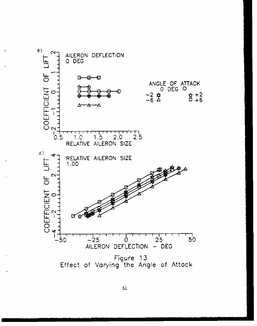
3. Effects of Varying the Angle of Attack
Typical results of the effect of varying the angle of
attack are graphically illustrated in Figure 13. As expected,
an increase in the angle of attack increased the value of CL.
The increase is constant regardless of the aileron size for
deflections up to 25'. Therefore, the cruise angle of attack
49
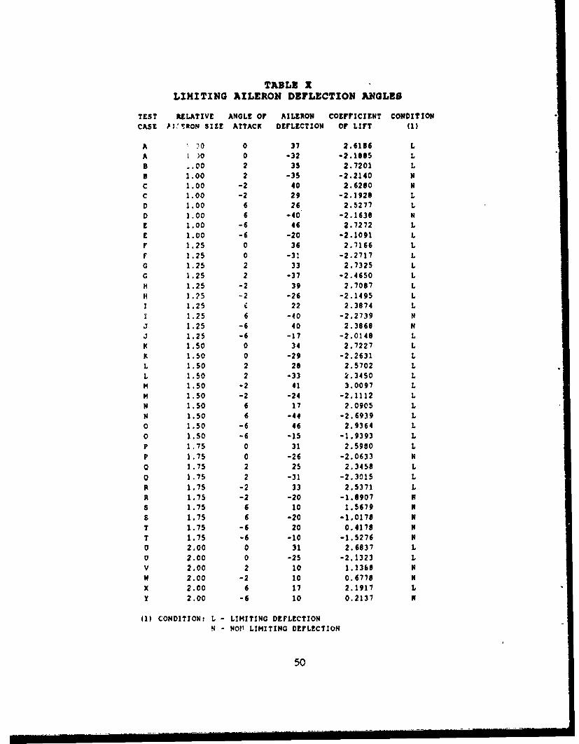
TABLE XLIMITING AILERON DEFLECTION ANGLE$
TEST RELATIVE ANGLE OF AILERON COEFFICIENT CONDITIONCASE WTRON SIZE ATTACK DEFLECTION OF LIFT (1)
A 10 0 37 2.6186 L
A 1 )0 0 -32 -2.1085 LB .00 2 35 2.7201 L
B 1.00 2 -35 -2.2140 NC 1.00 -2 40 2.6280 Nc 1.00 -2 29 -2.1920 LD 1.00 6 26 2.5277 L
D 1.00 6 -40 -2.1630 NE 1.00 -6 46 2.7272 LE 1.00 -6 -20 -2.1091 Lr 1.25 0 36 2.7166 L
F 1.25 0 -31 -2.2717 LG 1.25 2 33 2.7325 LG 1.25 2 -37 -2.4650 L
H 1.25 -2 39 2.7087 L
H 1.25 -2 -26 -2.1495 LI 1.25 E 22 2,3874 L
1 1.25 6 -40 -2.2739 N
3 1.25 -6 40 2.3868 N3 1.25 -6 -17 -2.0140 LK 1.50 0 34 2.7227 L
K 1.50 0 -29 -2.2631 LL 1.50 2 20 2.5702 L
L 1.50 2 -33 2.3450 LM 1.50 -2 41 3.0097 L
M 1.50 -2 -24 -2.1112 L
N 1.50 6 17 2.0905 LN 1.50 6 -44 -2.6939 L0 1.50 -6 46 2.9364 L
0 1.50 -6 -15 -1.9393 LP 1.75 0 31 2.5980 L
P 1.75 0 -26 -2.0633 N
O 1.75 2 25 2.3458 Lo 1.75 2 -31 -2.3015 L
R 1.75 -2 33 2.5371 L
R 1.75 -2 -20 -1.6907 N$ 1.75 6 10 1.5679 N
S 1.75 6 -20 -1.0170 NT 1.75 -6 20 0.4178 N
T 1.75 -6 -10 -1.5276 N0 2.00 0 31 2.6837 L
0 2.00 0 -25 -2.1323 LV 2.00 2 10 1.13b6 Nw 2.00 -2 10 0.6770 N
X 2.00 6 17 2.1917 L
y 2.00 -6 10 0.2137 N
(1) CONDITION: L - LIMITING DEFLECTION
N - NO?' LIMITING DEFLECTION
50
B)- - AILERON DEFLECTION
L 0 DEG
UL-O) 13-- - -S
ANGLE OF ATTACK0- GeC) 0 DEG O
LU -6 L ~ 0+6
LL
0I "' , , I I I I , I I i I I I i i i I
0.5 1 .0 1.5 2.0 2.5RELATIVE AILERON SIZE
A % • RELATIVE AILERON SIZE
_ 1.00
© -LC%)
F-
LU
0
-50 -25 0 25 50AILERON DEFLECTION - DEG
Figure 13Effect of Varying the Angle of Attack
51

need not be a concern when implementing any changes to the
aileron except for deflection angles in excess of 25". Figure
13B shows the effect of increasing the angle of attack alone
(without aileron deflection).
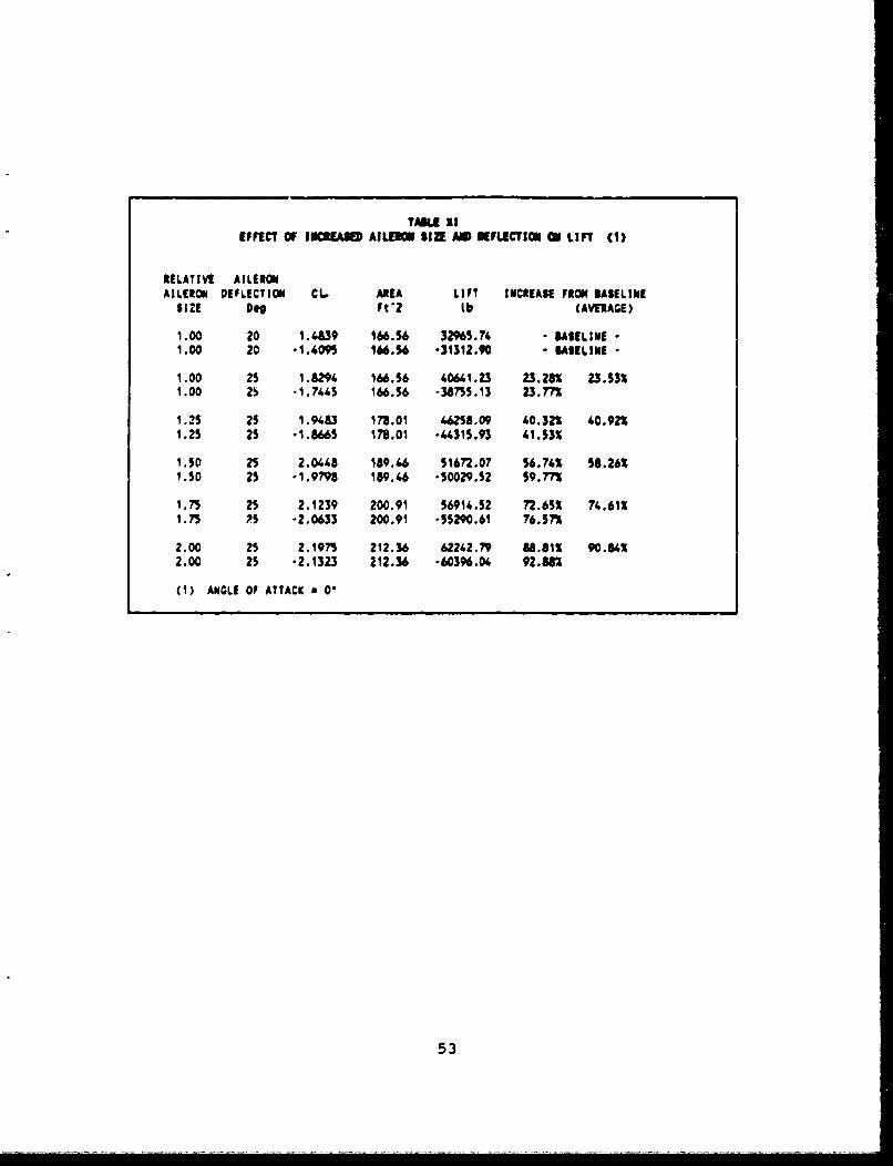
4. Combined Effect of Increased Aileron Size and
Deflection
Combining the results of an increase in both aileron
size and deflection would result in a larger rolling moment
than has been discussed thus far for each Jndividual
improvement. As discussed previously, a total aileron
deflection of ±25" is a reasonable modification. Table XI
shows the resulting lift for ±25° deflection in combination
with an increased aileron size. These results are graphically
displayed in Figure 14. As can be seen, combining the
increased deflection with an increased aileron chord creates
a much larger rolling moment. For a 50% increase in aileron
chord and 5 additional degrees of deflection there is almost
a 60% increase. This is not quite the desired target but it
does represent a significant improvement in roll response.
52
TAME XIEFFECT OF INUCEASEA) AILE1101 SIZE AM KFLECTIOM ON LIFT (1)
RELATIVI AILERONAILERON DEFLECTION CL. AREA LIFT INCREASE FRON BASELINE
SIZE D" Ft "2 lb (AVERAGE)
1.00 20 1.48W9 166.56 32965.74 - BASELINE •1.00 20 -1.409m 166.56 -31312.90 * BASELINE -
1.00 25 1.8291 166.56 40661.23 23.28% 23.33%1.00 26 -1.7445 166.56 -38755.13 23.77%
1.25 25 1.9483 178.01 46258.09 60.32% 40.92%1.25 25 -1.665 178.01 *66315.93 61533%
1.50 25 2.0448 189.66 51672.07 56.74% S8.26%1.50 25 -1.9798 189.466 -50029.S2 S9.77%
1.75 25 2.1239 200.91 5691%.52 72.65% 74.61%1.75 As -2.0633 200.91 -5S290.61 76.37%
2.00 25 2.1975 212.36 62242.79 88.813 90.84%2.00 25 -2.1323 212.36 -60396.04 92.882
(1) ANGLE OF ATTACK 0 0'
53

100- RESULTS SHOW THE x INCREASESWH E N C O M P A R E D TO T H E O R IG IN A L
AIRFOIL WITH A DEFLECTIONOF +/- 20 DEG
o80-
I--Z
:60-
-J AILERON DEFLECTION:_4o +/- 25 DEG
240-
_C 0-
0] I II
1,00 1.25 1.50 1.75 2.00RELATIVE SIZE OF AILERON CHORD
Figure 14Effect of Increosed Aileron
Size ond Deflection
54

V. CONCLUSIONS
Tests were conducted on the P-3C OFT's at NAS Moffett
Field to determine a realistic "target" for improvements to
the lateral response characteristics of the P-3C aircraft.
Doubling the current rolling moment coefficient of the
aircraft was determined to be the goal. Several ways to
achieve this goal have been discussed. Among these are:
(1) Reduce the control forces.
(2) Reduce the inherent delay of transmitting the control
inputs to the control surfaces.
(3) Increase the total aileron deflection.
(4) Increase the aileron chord.
(5) Utilize the flaps for roll assist.
One method that was evaluated, but is not appropriate for
consideration, is the utilization of asymmetric thrust for
roll initiation.
A 2-D airfoil computer code was run to determine to what
extent the current airfoil section of the P-3C wing would have
to be altered to obtain the goal of doubling the value of C,.
It was found that by increasing the aileron deflection from
an average of ±20" to ±25" and increasing the aileron chord
by 50%, a 58% increase in C1 could be realized. Although this
does not reach the goal of a 100% increase, it does provide
for a significant increase in lateral control response. An
55
increase in aileron size and deflection used in conjunction
with some of the other suggested modifications would certainly
approach the desired goal.
56

VI. RECOM(ENDATIONS
Prior to incorporating any of the suggested modifications,
it is recommended that an investigation of the structural
impact on the airframe should be conducted. Additionally,
further research should be conducted to determine the
following:
(1) The feasibility of reducing the control forces.
(2) Ways of reducing the delays inherent in transmitting
the control inputs to the control surfaces.
(3) The effect of adding spoilers and stall fences.
(4) The effect of using an active flap system.
(5) The optimal airfoil geometry for an increased aileron
chord.
57

LIST OF REFERENCES
1. NAVAIR 01-75PAC-I, NATOPS Fliaht Manual. Navy Model P-3CAircra, of 15 Nov 79, with Change 3, of 1 Mar 81.
2. Lockheed California Company, Orion Service Digest, Issue8, Jan-Mar 1964.
3. Lockheed California Company, Orion Service Digest, Issue9, Apr-Jun 1964.
4. Lockheed California Company, Orion Service Digest, Issue10, Jul-Sep 1964.
5. NATC Report of Test Results SA-14R-81, Navy Evaluation ofthe F/A-18A AirD).ane with Roll Rate ImprovementsIncorporated, by CDR W. Copeland USN, Mr. B. Kneeland,LCDR K. Grubbs USN, and Mr. C Sean, 23 Mar 1981.
6. NATC Technical Report, Final Report, SA-35R-82, Ev aof Proposed F-4S Airplane Lateral/Directional FlightControl System Modifications (ROLL MOD), by LCDR G. J.Rose USN and Mr. W. R. Dixon, 20 Jul 1982.
7. NATC Report of Test Results AT-7R-79, Evaluation of Effectof Removal of Aileron/Rudder Interconnect on FlyingOualities of P-3B/C Airplane, by LT J. Keen USN and Mr.R Lockhard, 21 May 1979.
8. NATC Technical Report, Final Report, AT-45R-82, FlightFidelity Evaluation of the P-3C Operational FlightTrainer, Device 2F8$7_(F), by LCDR G. C. Hill USN and Mr.K. A. Zimmerman, 2 Mar 1983.
9. Utilization Handbook for the P-3C Operational FlightTrainer. Device 2F87-F, Compiled by NTSC, Orlando, FL,Revised Sep 85.
10. USNTPS-FTM No. 103, Fixed Wing Stability and Control.,Theory and Flight Test Techbnicues, of 1 Jan 75 (RevisedI Aug 77).
11. Naik, Dinesh, User's Guide for MULTSEP - A ComDuterProg am for the Analysis of Subsonic Separated Flow Aroundan Airfoil with a FlaE (Program Author: R. Elangovan;Wichita State University 1982), Ph.D. Dissertation, TexasA&M University, Spring 1984.
58

12. Anderson, Murray Belser, Analysis and Q=timization ofIncompressible Separated Flow around an Airfoil with twoFinite-Gap Flaps, Master's Thesis, Texas A&M University,May 1988.
13. Abbott, Ira H., and Von Doenhoff, Albert E., fl-ryQoWing Sections, Dover Publications, New York (1959).
59

APPENDIX A
TABLES
60
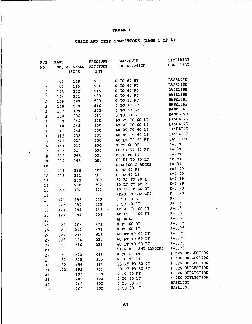
TABLE I
TESTS AND TEST CONDITIONS (PAGE 1 OF 4)
RUN PAGE PRESSURE MANEUVER SIMULATOR
NO. NO. AIRSPEED ALTITUDE DESCRIPTION CONDITION
(KCAS) (FT)
1 101 196 517 0 TO 60 RT BASELINE
1 102 195 524 0 TO 60 RT BASELINE
2 103 202 545 0 TO 60 RT BASELINE
2 104 201 553 0 TO 60 RT BASELINE
2 105 199 583 0 TO 60 RT BASELINE
3 106 200 516 C TO 6b LT BASELINE
3 107 199 512 0 TO 60 LT BASELINE
3 108 200 491 0 TO 60 LT BASELINE
4 i09 244 500 60 RT TO 60 LT BASELINE
4 110 245 500 60 RT TO 60 LT BASELINE
4 111 243 500 60 RT TO 60 LT BASELINE
4 112 238 500 60 RT TO 60 LT BASELINE
5 113 202 500 60 LT TO 60 RT BASELINE
6 114 210 500 0 TO 60 RT K=.99
7 115 204 500 60 LT TO 60 RT K=.99
8 116 269 500 0 TO 60 LT K=.99
9 117 193 500 60 RT TO 60 LT K=.99
10 HEADING CHANGES K=.99
I1 118 216 500 0 TO 60 RT K=1.99
12 119 211 500 0 TO 60 LT K=1.99
13 200 500 60 R4 TO 60 LT K=1.99
14 200 500 60 LT TO 60 RT K=1.99
15 120 182 402 60 LT TO 60 RT K=1.99
16 HEADING CHANGES K=1.99
17 121 196 449 0 TO 60 LT K=1.5
28 122 197 518 0 TO 60 RT K=1.5
19 123 193 543 60 RT TO 60 LT K=1.5
20 124 191 558 60 LT TO 60 RT K=1.5
21 APPROACH K=1.5
22 125 204 472 0 TO 60 RT K-1.75
23 126 219 474 0 TO 60 LT K=1.75
24 127 214 617 60 RT TO 60 LT K=1.75
25 128 196 520 60 RT TO 60 LT K=1.75
26 129 216 523 60 LT TO 60 RT K=1.75
27 TAKE OFF AND LANDING K-1.75
28 130 223 414 0 TO 60 RT 4 DEG DEFLECTION
29 131 218 355 0 TO 60 LT 4 DEG DEFLECTION
30 132 196 484 60 RT TO 60 LT 4 DEG DEFLECTION
31 133 192 701 60 LT TO 60 RT 4 DEG DEFLECTION
32 200 500 0 TO 60 RT 4 DEG DEFLECTION
33 200 500 0 TO 60 LT 4 DEG DEFLECTION
34 200 500 0 TO 60 RT BASELINE
35 200 500 0 TO 60 LT BASELINE
61

TARLZ I
TZSTS AND T&ST CONDITIONS (FAGZ 2 Or 4)
RUN PAGE PRESSURE MANEUVER SIMULATORNO. NO. AIRSPEED ALTITUDE DESCRIPTION CONDITION
(KCAS) (FT)
36 200 5 00 60 RT TO 60 LT BASELINE37 200 500 60 LT TO 60 RT BASELINE38 200 500 90 DEG CW BASELINE39 200 500 30 DEG CCW BASELINE40 275 500 0 T6 60 RT BASELINE41 275 500 0 TO 60 LT BASELINE42 11,75 500 0 TO 60 LT BASELINE43 275 51,10 0 TO 60 RT BASELINE44 275 500 0 TO 60 RT BASELINE45 275 Soo 0 TO 60 LT BASELINE46 275 500 60 LT TO 60 RT BASELINE47 275 500 60 RT TO 60 LT BASELINE4e 350 500 0 TO 60 RT BASELINE49 350 500 0 TO 60 RT BASELINE50 350 500 0 TO 60 LT BASELINE51 350 500 0 TO 60 LT BASELINE52 350 500 60 RT TO 60 LT BASELINE53 350 500 60 LT TO 60 RT BASELINE54 350 500 60 LT TO 60 RT BASELINE55 200 500 0 TO 60 RT K=1.7556 200 500 0 TO 60 RT K=1.7557 200 500 0 TO 60 RT K-1.7558 201 194 Soo 60 RT TO 60 LT K-1.7559 202 195 500 60 RT TO 60 LT K=1.7560 203 195 500 60 RT TO 60 LT K=1.7561 204 189 500 60 LT TO 60 RT K=1.7562 205 202 500 60 LT TO 60 RT K-1.7563 206 205 500 60 LT TO 60 RT K-1.7564 207 204 500 60 LT TO 60 RT K-1.7565 275 500 0 TO 60 RT K-1.7566 275 500 0 TO 60 RT K-1.7567 275 500 0 TO 60 RT K-1.7568 275 500 0 TO 60 LT K-1.7569 275 Soo 0 TO 60 LT K-1.7570 275 Soo 0 TO 60 LT K-1.7572 208 314 500 60 RT TO 60 LT K-1.7572 209 281 Soo 60 RT TO 60 LT Kul.7573 210 281 Soo 60 RT TO 60 LT K-1.7574 212 291 500 60 RT TO 60 LT K-1,7575 212 328 500 60 LT TO 60 RT K-1.7576 213 301 500 60 LT TO 60 RT K-1.7577 214 309 500 60 LT TO 60 RT X-1.7579 215 294 500 60 LT TO 60 RT K-1.75
62

TABLE I
TESTS AND TEST CONDITIONS (PAGE 3 OF 4)
RUN PAGE PRESSURE MANEUVER SIMULATOR
NO. NO. AIRSPEED ALTITUDE DESCRIPTION CONDITION
(KCAS) (FT)
79 216 282 500 60 LT TO 60 RT K=1.75
90 217 257 500 60 LT TO EC RT K=1.75
81 218 263 500 60 LT TO 60 RT K=1.75
82 APPROACH AND LANDING K=1.75
83 219 170 10000 30 bEG CCW BASELINE
84 220 178 10000 30 DEG CCW BASELINE
85 221 177 1000: 30 DEG CCW BASELINE
86 222 175 10000 90 DEG CW BASELINE
87 223 178 10o00 90 DEG CW BASELINE
88 224 181 10000 90 DEG CW BASELINE
89 225 173 10089 ASYMMETRIC THRUST BASELINE90 226 184 10031 ASYMMETRIC THRUST BASELINE
91 350 500 0 TO 60 RT K=1.75
92 350 500 0 TO 60 RT K=1.75
93 350 500 0 TO 60 LT K=1.75
94 350 500 0 TO 60 LT K=1.75
95 227 348 500 60 LT TO 60 RT K=1.75
96 228 345 500 60 LT TO 60 RT K=1.75
97 229 360 500 60 RT TO 60 LT K-1.75
98 230 361 500 60 RT TO 60 LT K=1.75
99 231 353 500 60 LT TO 60 RT K-1.75
100 232 342 500 60 RT TO 60 LT K-1.75
101 233 361 500 60 RT TO 60 LT X=1.75
102 234 369 500 60 RT TO 60 LT K=1.75
103 500 ASYMETRIC THRUST K=1.75
104 500 ASYMETRIC THRUST K=1.75
105 235 171 10000 90 DEG CW K=1.75
106 236 172 10000 90 DEG CW K=1.75
106 237 174 10000 90 DEG CW K-1.75
107 238 168 10000 30 DEG CCW K-1.75
108 239 171 10000 30 DEG CCW K-1.75
109 200 500 0 TO 60 RT 8 DEG DEFLECTION
110 200 500 0 TO 60 RT 8 DEG DEFLECTION
111 200 500 0 TO 60 RT 8 DEG DEFLECTION
112 200 500 0 TO 60 RT 8 DEG DEFLECTION
113 200 500 0 TO 60 LT 8 DEG DEFLECTION
114 200 500 0 TO 60 LT 8 DEG DEFLECTION
115 200 500 0 TO 60 LT 8 DEG DEFLECTION
116 200 500 0 TO 60 LT 8 DEG DEFLECTION
117 200 500 0 TO 60 LT 8 DEG DEFLECTION
118 200 500 0 TO 60 RT 8 DEG DEFLECTION
119 240 247 500 60 RT TO 60 LT 8 DEG DEFLECTION
120 241 190 500 60 RT TO 60 LT 8 DEC DEFLECTION
63
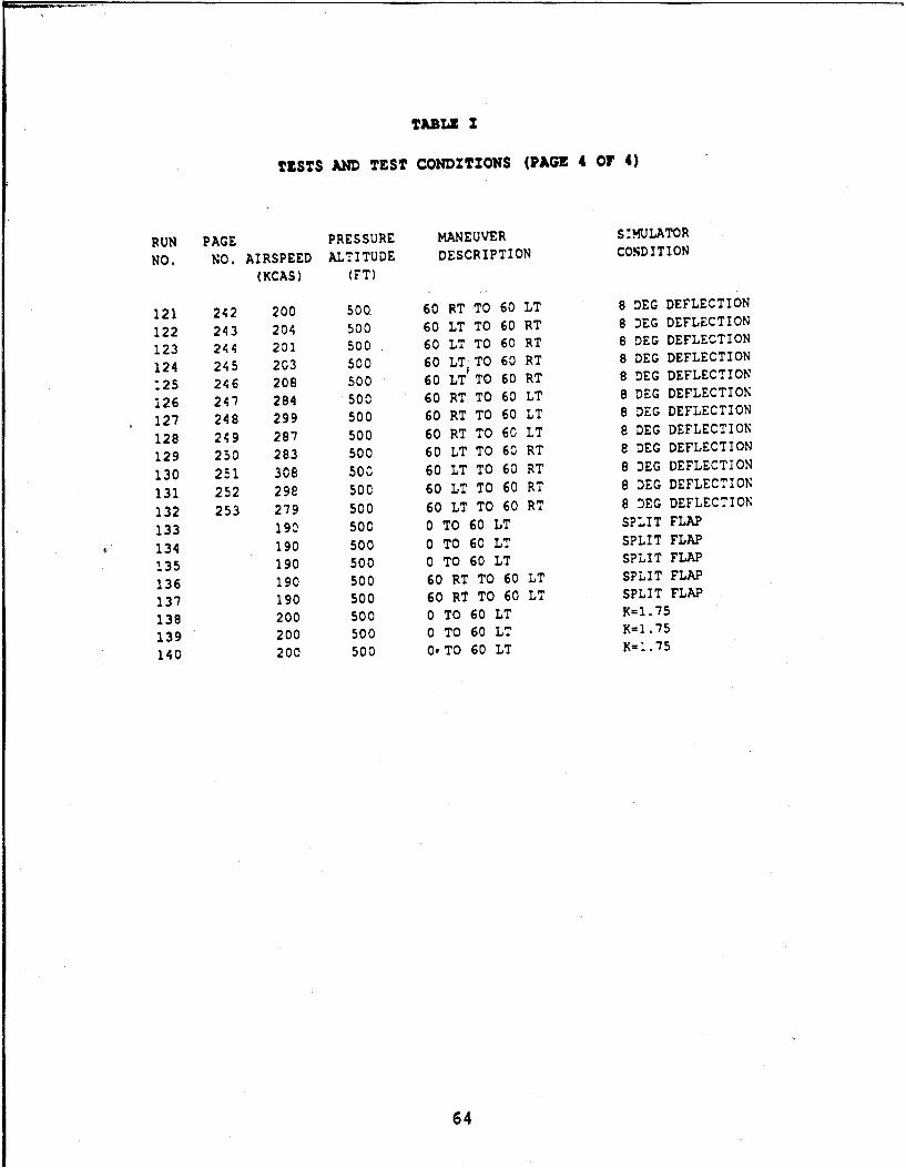
TABLE Z
TESTS AND TEST CONDITIONS (PAGE 4 OF 4)
RUN PAGE PRESSURE MANEUVER S:MULATOR
NO. NO. AIRSPEED ALTITUDE DESCRIPTION CONDITION(KCAS) (FT)
121 242 200 500 60 RT TO 60 LT 8 DEG DEFLECTION
122 243 204 500 60 LT TO 60 RT 8 DEG DEFLECTION
123 244 201 500 60 LT TO 60 RT 8 DEG DEFLECTION
124 245 203 500 60 LTTO 60 RT 8 DEG DEFLECTION
.25 246 208 500 60 LT'TO 60 RT 8 DEG DEFLECTION
126 247 284 500 60 RT TO 60 LT 8 DEG DEFLECTION
127 248 299 500 60 RT TO 60 LT 8 DEG DEFLECTION
128 249 287 500 60 RT TO 60 LT 8 DEG DEFLECTION
129 250 283 500 60 LT TO 60 RT e DEG DEFLECTION
130 251 308 50C 60 LT TO 60 RT 8 DEG DEFLECTION
131 252 298 500 60 LT TO 60 RT 8 DEG DEFLECTION
132 253 279 500 60 LT TO 60 RT 8 DEG DEFLECTION
133 190 500 0 TO 60 LT SPLIT FLAP
134 190 500 0 TO 60 LT SPLIT FLAP
135 190 500 0 TO 60 LT SPLIT FLAP
136 190 500 60 RT TO 60 LT SPLIT FLAP
137 190 500 60 RT TO 60 LT SPLIT FLAP
138 200 500 0 TO 60 LT K=1.75
139 200 500 0 TO 60 LT K=1.75
140 200 500 0oTO 60 LT K=..75
64

(NN 1. 00 m (N N e N N
La . N0lM (N N (
N r- N
=i #- DV% oenq nC %n U - N -r M W %.
0 -w -N m -
0. ON IMcr
No Ný N~ N NN NN0- (NN N NN
- n0NmWa C&-- 00 ( Ln rW.- L . L 4
LL r'- LM '~ CP W U t~ Nt ~ ~ L M DL M M N 0 % TS ý4 w r- %.
Ir I N N I I I N ci
0 1
N- Iv 0 N Dr-*V Itva
N w
0. ( N( (N N N N w -WN(NwNm(m (NN mNmNN w
U)~ ~ Li I- 9 0 ~ N 0 N % N L
19 0 00 w0 . )- (N0 ~ 0 w 'N.0c
o a
0000040 0 0 NN000 o. . W 1 N0N0 N N N
1 - O%4~ P-4 00 ý0~ N- NU N0% N% N 0 ~ 4~
cc ~% Q W ~ U~ N N
65I I I I
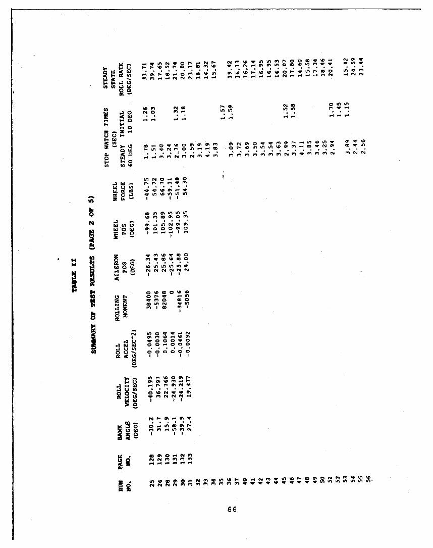
, w %n q0 N hn~ A 00 r v Wf. q%
dCn~04 M Wi
" 0
-Z. .
-1 . . . . .-
%n4 C.4 0. ý4 0
= 0 In WlV
OW IAO~l~ 0 6;CJO ý,0 W cy 0 0
.4 ofa40 NN
inN- W -Ii
04 M' I CD I
M c
wow @440@00
00 8 C; C;I I
' 34 ow C.4 r(4- or- 4 0
#4 In I0
in P4 LM I"-'.
qOCOon
0 W 4aW w, 00MWow0coýN Vn
Oi% inini0i000i i
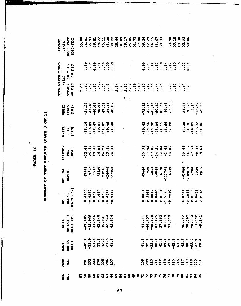
0-4M-4N-4~N~@4 0%0l~~r 00 fn
W4 0 M 0 M m~ 0 .4m0 ~~ 0 0 m%
zz-
a w 0 N w z 0m t m % - m -4%D m m -4 N %D N
me %a 4N W N CD 4 0 M M r. N 0
Iau ). . .i. 1 ý1ýO !O
cc m- m 0 -m00i sm r nNa
In W I Il I
m' &1 -4 M.DODN
N N NN N4-4-4N 4 ý4-
H H OD N. D0C D% O00 N0 4m N 1.-4-4.- 0 .V N O-4 CID IN I
v I r r14 %0o' o fnw ~ w o o
"40
C 0 w as r'o 4m tAOV - 4'DMc k ýo r.O .
uD NO N wE 0.44 r0- 0 .-a000 00otnoooUoo ONOOO
000 00 00 0 0 0
0% D 4Ifw,4m q 4 ey~4 %~ N n -4r-O%%0M A.4 04 w ".i ý0r h4y -
V(a. 41 PII I ;r ýa z
m o m 1414 4 N M w .-4 m4 N Lm m N km ?fP 150 w %o&Mw L v%D % rmV D % Dv %Se I I II I I III 1
epo co 0 00 -4 V4 V -4 V4 V4 .4r4N
67

W .O .D U4 0 af a
0.4 IA .-4 MW
0.4 0
Z ..)
in ODw kn c irM M (NJ
'E2 o' . . -4.(N .- 4. .
L-10: cc l~ N m 0% %0 N c4I
= 0 VI v vN NN4 WW! O.%0
%D N4 .4 f.N- rV f O -r o
ON 0m aU~ 0 0N ODf-%n O
N m r-Nk 0wNw0f a NC 0 7
.4 ~ N N N -4.. - I 4
jnviq -0 1000 0 to- 4 %
c4 MO NO w wr L f % r 0 % 0 0 U m r
NN( - nM LM M M M( N I 4 40. q
.4VM N( u- 0MM.
czI III 0 1 111 1 1
Wi
f.V4r-0 - - L ONN NMM N M %NMM0 -
m m 0CDe40 - -4 -40 4- M N O -4N-4 -4 -44--
4 ;C;C 0 9Q 0 C 44r6v8r

OnM O 4 orV:WMWN N NO
b-4 P44 14 It --p 41 41. - 4ý
-z-u u
o 43 NM mM o N N N NM w a N N N No w N NZ N N h N rN w N0- 1-
.4 ~ 0 0 qw q % m N 0 %D~ N %lV q , %Vcc%
0%O'V0.-4U,0ULA 00
N~ N
' II.4 q 410C pq00NvN 0 N M V 0 0 %Af- w
N% NC U, N% 0. go U, ý4 -4 N
Ifl N m f" N 0pq 0 ,0% Is N "r 4 C
W q0000 NO 00 m0 0 000
II'
C~ N m MN in w f- 0 ol N, "I N0Iv~ v. N .0 I, I I .N tm M 0 Lm
NNNNN N N N N N - N- N N N
W Ln ~ f 0 ft 0 0r UP N N 0 W f% WM 0% P"NMWV0 -W02P1a P4, P4 V4 V- 4 N, N N0 N M M MV
f-fg~ f- - - - - 4P4 - - O " - - - P4r 4i - - 4ý
0N VU Wt.0 %09N
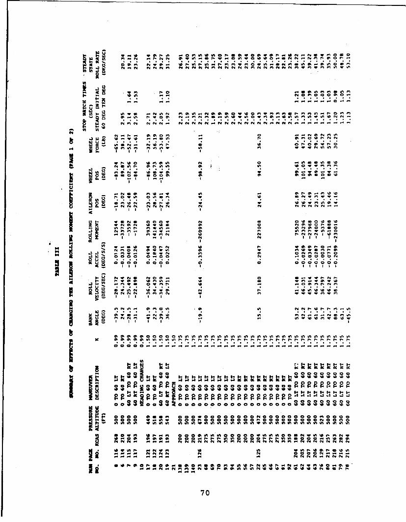
a~ 94% N 4ry O
W dc 0%I0M U~*NO in 000
" i on NMN NN Nf4 Ne4NN N NN NN qN NNN
.4 %V m%n m ~ in In 0W %N kn0
wo I W WNl
w?~C40% N 1 UU 0%U m
a v 0 r.~ N 0 ~ M
I r 'r v4 ?4in
W , 0, .. W N.
Gý UM% Mf-' in %0%D %.0%O NN N C4 N Nn f"f"fmm N Ww "
in m N .N m VO' U
0 fini "k nn00o0oo% oWf. o% 6, mn o o%no nn
NM 0~ %4 0 C; C;WI.
.M~~~~ aI 0U~ aN -NI
14WU W~ff W 0*aaoo g
000 m Ion000O WI
'A W0 S inM. q M W %n a0 %U., X 114 -40zP-N
Po OM ONkNNN6 -MMM * W WUMU
0%WU4 ~ ~ ~ P .-4% 04 N ~~ U U
MNNM U'70

0 14m -4In 06M f 0 L 0 U3"~ in0 % f.aN W afn
14 .4
w4 c,.4 r:. 0 .r
fn 0 q m nl- D0%i %ý
6nM W W W ~ ~ 8 - % 44 rI 0%
w 0
t4%P0 4 D % D t 4 2ýqw % &t % 0C aon
0 f -kn NMNNN I MN NONN
P- l S' 2Z 1D v 1a 4*1 N OI11 l
OWq N U4 O N V WMN N ~ N In %4DP.~O%.UD.W4DO N@~N Non
0 0 LM 0 0 w0ý 0%NVNU W fnf.0 n O
64%0M ~ U @ . % W N in C04 .rD Tý % gý 0ý%0 r 0 n 40% W fn - 1ýC4 0 '
O O W N O W M W W C 0 faN MW) N Nw 0 0 0 WMN a . 4 .4WH ~ 111 1111 1111 I
04 W V! C 9 9 C! Cý 9 19C! V 9 9 C 9 9 9%U*N4 O CW0N4.T~ N i. ! coofl
dt 0r 0k 4 n3 0 NWW M M4MnU W NnM M.4 c
'0 mA f"t f4 it4 IA nA 6n ry MD IA wt IA f4 r- 0AI AitI t AI A~ tiHt 0 0ft1
9~~~~ ~ ~ ~ Oý I 'ý0 ý"1 ý l:.1 :9V0 4-r44 A w0 vV W a ,4 r -
4 oeoocoooeeaoeeoc*aocc coo
OOOOO OOOOO OC~o~~oOOR gA I''il 0
Ooee~~e~0ooe ~ coaoor0ee
-4eUin .1 S 1 G h.1 0IonN Vl0,o .01 0 0%on-o W
of., 0tS~ .. I S4 W w N 9 .4' 1I 0 a.1m A XA .0.04 m M M MM.A .M.4 14 1-4 .4
NftM0 0NNOO NMMMM MM 00
O ~ I vs*t ~~A~w ~-4 -44- -4-4 -4-.4
71.

APPENDIX 3
PROGRAM LISTING: WINGIT
C THIS PROGRAM IS DESIGNED TO CONVERT ANY SPECIFIC AIRFOILC INTO ANY OTHER AIRFOIL OF THE SAME FAMILY. IT CAN CHANGEC THE THICKNESS AS WELL AS THE AILERON SIZE AND DEFLECTION.CC COORDINATE TRANSFORMATION PROGRAMCC THIS SECTION TAKES A GIVEN INPUT FILE FOR SEARCHSE AND CONVERTS ITC TO ANOTHER INPUT FILE W0R SEARCHSE WITH A DIFFERENT THICKNESS AIRFOIL
COJAGO/SUBSSRX(200O,R2(ZOO),ARX(200),ARZ(200)CHARACTER FLNAM*2OCHARACTER IITLE*8OCHARACTER FNEW*ZOCHARACTER THK,AS.DAWEITEC*,300)
300 FORMAT('ENTER THE DATA FILE THAT CONTAINS YOUR DATA')READ(*,101) FLNAM
101 FORHAT(A20)WRITE(t,t) 'INPUT NEW DATA TITLE'READ(-,1Od.) FNEWOPEN (UN IT.., FILEuFLNAI4 ,STATUSu' OLD)OPEN (UN IT-7, FILE 'ENE W,STATUS' 'NEW')READ(4,1O2) TITLE
104 FORKAT(A2O)READ(4,*) NALPHAREAD(4,-) ALPHAREAD(4,-) NOf,NWDEREAD(4,-) AMIII$,PO,TO,CREF,VKO,DAHPREAD(4,-) NIP]
REA(4,*) SFACTREAD(4,*) HMAXREAD(4,-) GAPHINREAD(.,-) KCAS,NTRAL,NTRtAU, ITSEPUWRITE(*,) 'ENTER X/C LOCATION OF THE AILERON PIVOT'READ(*,-) EAPWRITE(-,*) 'ENTER WING CHORD LENGTh IN FEET'READ(*,*) WCWRMITE(*,*) 'DO YOU WANT TO CHANGE THICKNESS7 (Y OR N)'READ '(A)',THKIF (THK.EQ.'N') GO TO 700WRITE(*,*) 'ENTER THE THICKNESS OF THE NEW WING STATION'
EAM(*,*) VSTWRIEC'') ENTER ORIGINAL WING STATION THICKNESS'
READ(*,*) WSTOCALL THICK(WST.NIPI,WSTO)
700 CONTI INUECC THIS SECTION WIL CHANGE THE RELATIVE AILERON CHORD LENGTHC THEN NONDIN4ENSIOWALIZE THE COORDINATES WITH RESPECT TO THEC NEW TOTAL AIRFOIL CHORD LENGTHC
WRITE(,') 'DO YOU WANT TO CHANGE AILERON SIZING? (Y OR N)'READ I(A)',ASIF (AS.EQ.*N') GO TO 800WRITE(*,*) @9Y WHAT FACTOR DO YOU WANT TO CHANGE AILERON CHORD?'WRITE(-,*) 'I.E. A FACTOE OF 2 WILL DOUBLE THE AILERON CHORD'READ",-) AILF
72

CALL INCAIL(NIPI,XAP,AILF)CC THIS SECTION WILL DEFLECT THE AILERON IN EITHER A POSITIVE (DOWNWARD)C OR NEGATIVE (UPWARD) DIRECTIONCtoo WRITE (*,) 'DO YOU WANT TO DEFLECT THE AILERON (i' OR N)P
READ'(A) ,DAIF (OA.EQ.$Nt) GOTO 200
850 WRITE (t,) 'ENTER AILERON DEFLECTION ANGLE-READ (*,*) DELAIF (DELA.EQ.O.O) GOT 200ZCALL AILDEF(DELA,NIPI,XAP,AC,WC)
CC THIS SECTION WRITES THE NEW DATA TO THE NEW DATA FILEC THIS FILE WILL SE IN A FORK RECOGNIZEABLE TO SEARCHSEC200 CONTINUE
WRITE(7,111) FNEWWRITE(7,112) NALPI4AWRITE(7,113) ALPHAWRITE(7,114) NOE,MCIEWRtTE(7,115) AMINF,PO,TO,WC,VKO,DANPWRITE(7,116) NIPIWRITE(7,117) (RX(N),RZ(N),Nul,NIPI)WRITE(7,118) SFACTWRITE(7,119) mNAxWRITE(7,120) GAPMINWRITE(7,1Z1) KCAS,NTRAL,NTRAU,ITSEPU
ill FORMAT (20M6)112 FORMAT (15)113 FORMAT (FIO.1)114 FORMAT (215)115 FORMAT C1O.2,FIO.2,F10.1,F1O.2,F1O.6,F10.2)116 FORMAT (I5)117 FORMAT (2FIO.5)118 FORMAT (F1O.1)119 FORMAT 0F10.2)120 FORMAT (FlO.3)121 FORMAT (415)102 FORMAT (A50)
CEND
CSUBROUTINE THICK(WST,NIPI,WST-O)
COMMON/SU6S/RX(200) ,RZ(200)DO 100 Ial,NIPIRZ( I )R2( I )STiWSTO
100 CONTINUERETURNEND
C
SUBROUTINE AILDEF(OELA,NIPI,XAP,AC,LJC)C
CWoN"/SUiSS/RX(200) ,RZ(200),ARX(200) ,ARZ(200)DELDELA*3.14159/180.0ANG*90.0413. 14159/180.0Km0DO 200 Im1,NIPIJuI*KIF(RX(I).LT.XAP) GO TO 300RADX*RX(lI)-XAP
73
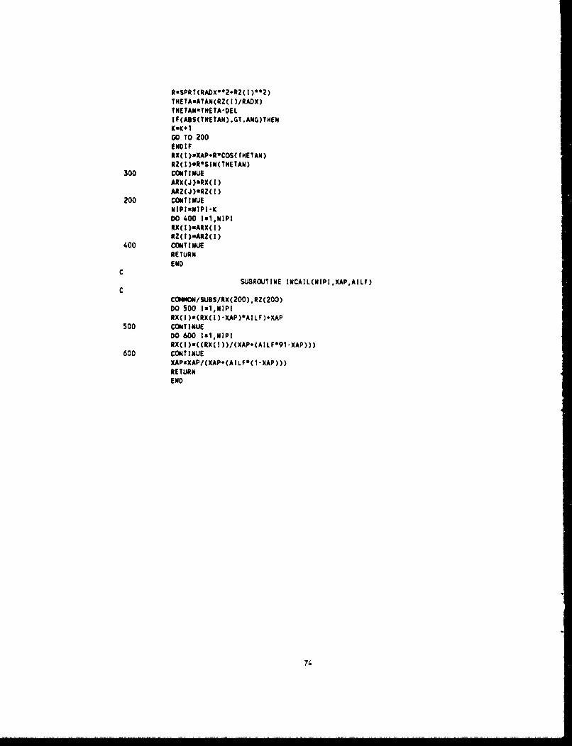
RaSPRT(RADX'?.*RZ( I )*2)THETAmATAN(RZ( I)/RADX)THETANaTMETA-DELI F(ABS(TNETAN) .GT .ANG)TNEN
GO To 200END IFRX(I )vXAP+RwCOS( rHETAN)RZ( I)@R'SIN(TNETAN)
300 CONTINUEARX(J)aRX(I)ARZ(J)nRZ(!)
200 CONTINUENIPluNIPI-KDO 1.00 Ial,NIPIRX(I)sARX(I)RZ(I)sARZ(I)
1.00 CONTINUERETURNEND
CSUBROUTINE INCAIL(NIPI,XAP,AILF)
CCW4VON/SUiBSIRX(200) ,RZ(200)DO 500 I.1,NIPIRX(I )sCRX( )-XAP)*AILF).XAP
500 CONTINUEDO 600 Ixl,NIPI*tx(I)s(CRX(I ))/(XAP+(AILF*91-XAP)))
600 CONTINUEXAPsXAP/(XAP+(AILF*(l-XAP)))RETURNEND
74.

APPENDIX C
FIGURES(AIRFOIL CODE DATA SUMMARY)
75

z Q)0 0
N0) 0LAJ
NJ 0(3 :3N/ LjU .
CN LL-J LL Q
Z + +
L0 0 0 4-J
w< N-N Li
0i N> u
Lu WOI~lWO
< -1 76

0Id-
z
3: CL00
V)
0 0
00
CNC .UJLD o
N (.0 Lij
Q< II<~~ C1 4 -u
r1 _ __ _ _ __ _ __ _ O
FT-71~ I I U f1 1 1 11 O
Iii] -iO IN]DW]OO30
77

z
00
-LU -c
CN
LO(
++ 0 <Z
N (9)LL
LiZ + +
CNLj. < zunJ iO INIO fO
< (if
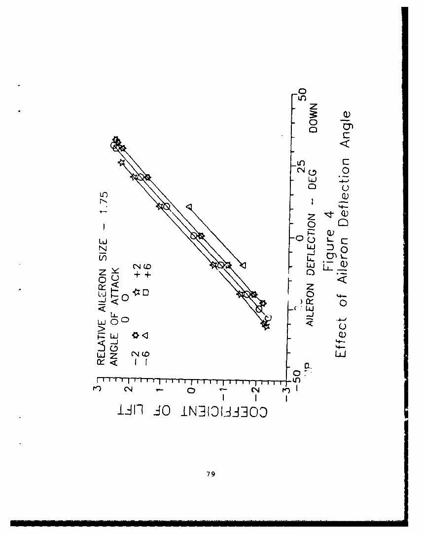
Q)
CNu 0
Ir Q)
RU)
N (0n 0 QZ + + a)
0 0
<I- *< U
4-
I T 1 -- '-r .L1)
I~f~JO IN-_q9IiAiO03
79
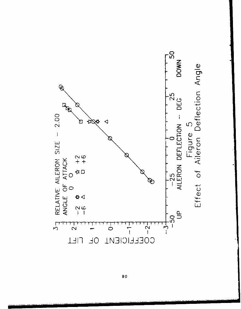
0
to
< ~z L0
U)
LU _No CC0~+ +
NLJ< -N L.L
ii0 0
uiO Uj
-'4
LLJ Z N LC
wez N(.CIIN
iA ý A iN101AI0
80

00
z Q
LLJ 0
LO~ Ur 0U
I <)
00<U 0JC l
NODN LLJD
IJ U-)OU)4
0D
_ U))
N CN
l~ii I JO IN]IDLAJ]OO3
81
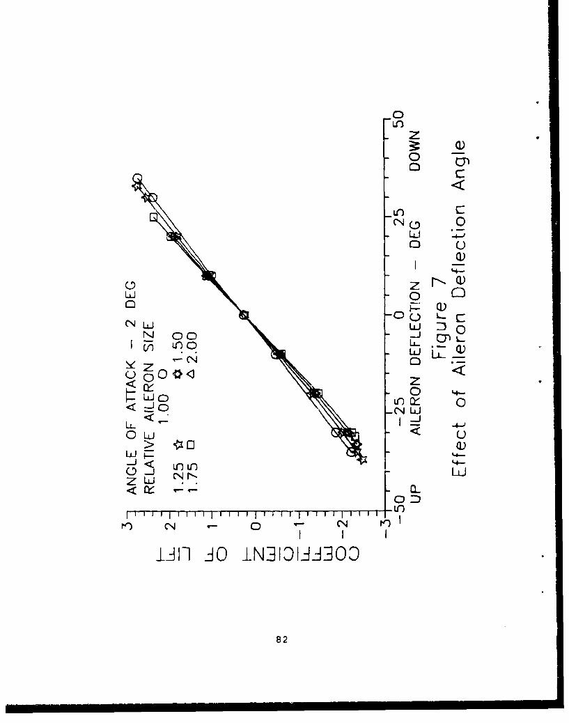
z0
L') 0LJ 40
Q)
0z Z~Q)LLJ 0
r' QN L~j C
1L U)
_ 0 z
LL - 'ý-4--1
0 Li < u
I N I"
LIif AO IN]1DLJ-i300D
82
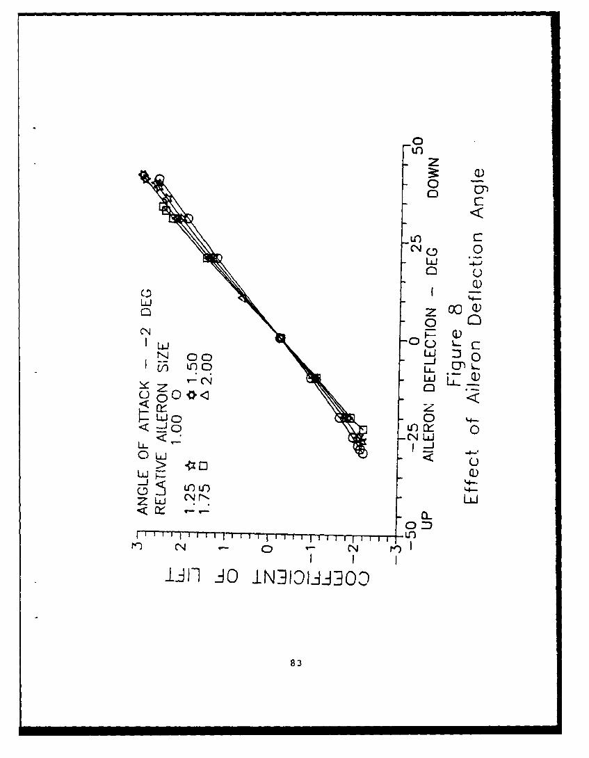
CU')
z3:: (1)
0
LC') C:CN~ 0
LuJ
LUJ0~ zXCl)
CN
L&5 C: LLLJ o)
zz
CN LLi
0 '-J -> uIi]uO1Nj1A0
:83

0U)z
0 0)
00
LJ -4-j0 uIQ)
0i
0 RQ)LLJ~ L cJ
N' 00 _j 0
V) uO* z Lclý 0
L)J 0
< o -cN LJ
OLAJ
z LuJZLUL
rn CN C C
84
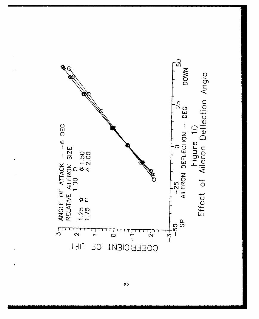
0'z
3r. Q00
UL)N 0 0
LUIoz
0 0LNj 00 -N LC) C LJ c
ce- z0 LLJQ
LU Q)
L ~O U-
I T T It U-)
85

0o W)
0 N
o N uiN 0
Q)z
-JL
Z Lkt -j -
0 CN(D UY+ +
UJ LL.
LL-< (i
0 004-
ZL uiu
CNC;
g cc
866
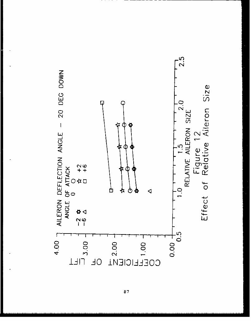
z0
N
o -qo LCN N 0
U))L
z-JL
Z Lj C)0 CN (o
-LJ < O z~114-< x
0LJ 0)
0iE '4-Q
W NC L)
C 00C C
00 0 0
I~flAO iNhDLIJA3OD
87

CN to
o o t0 I-
C) 0CNN
LLi
o U
< ,Li--
-LJ NO <
LA 0Cy- -4-
u- LjLJ-LJ>
00 L 0
CX u
Llii OINh O
88
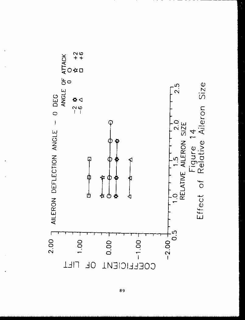
C0U-)0
LiZ*Zc\(r CN
Ld z <
CN LN
LDZ 0z
<0
L 0 LU
zU
o 0
0 00 0
CNJ 6 CN
89

0 +0+1
i) n Q)LJ N0
-ý LL
w~ NN
(3
0 :
C-, ULL-LUJLL.
LUL
Z U'
o~ 0)
904
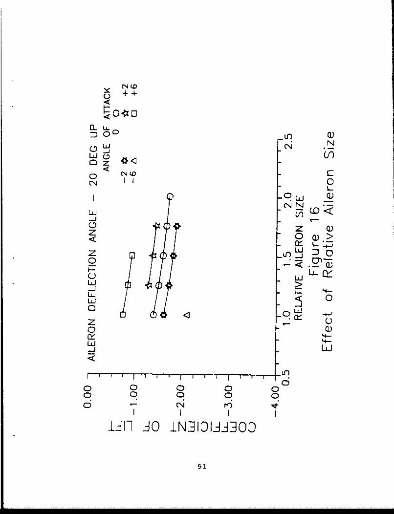
+ ++
:DO 0 LO) Q)N
UJ C*4o) 0CN0
-CN N
(3z Q)
z u0J>
C0)
LUJ
LLUCL !1 0L
z L)
LU
0 0 CD 0 00 C0 C 00
Iii iý O IN]hDLiS-JOO
91

CL LCoJ CN(N
1 0L-
9LLJ _)
N NN
0 z<OQ>
z0Q
LL FZd 0
o 0r'4
LUJ
000 0
LJIi AC INAIDIAA]30
92
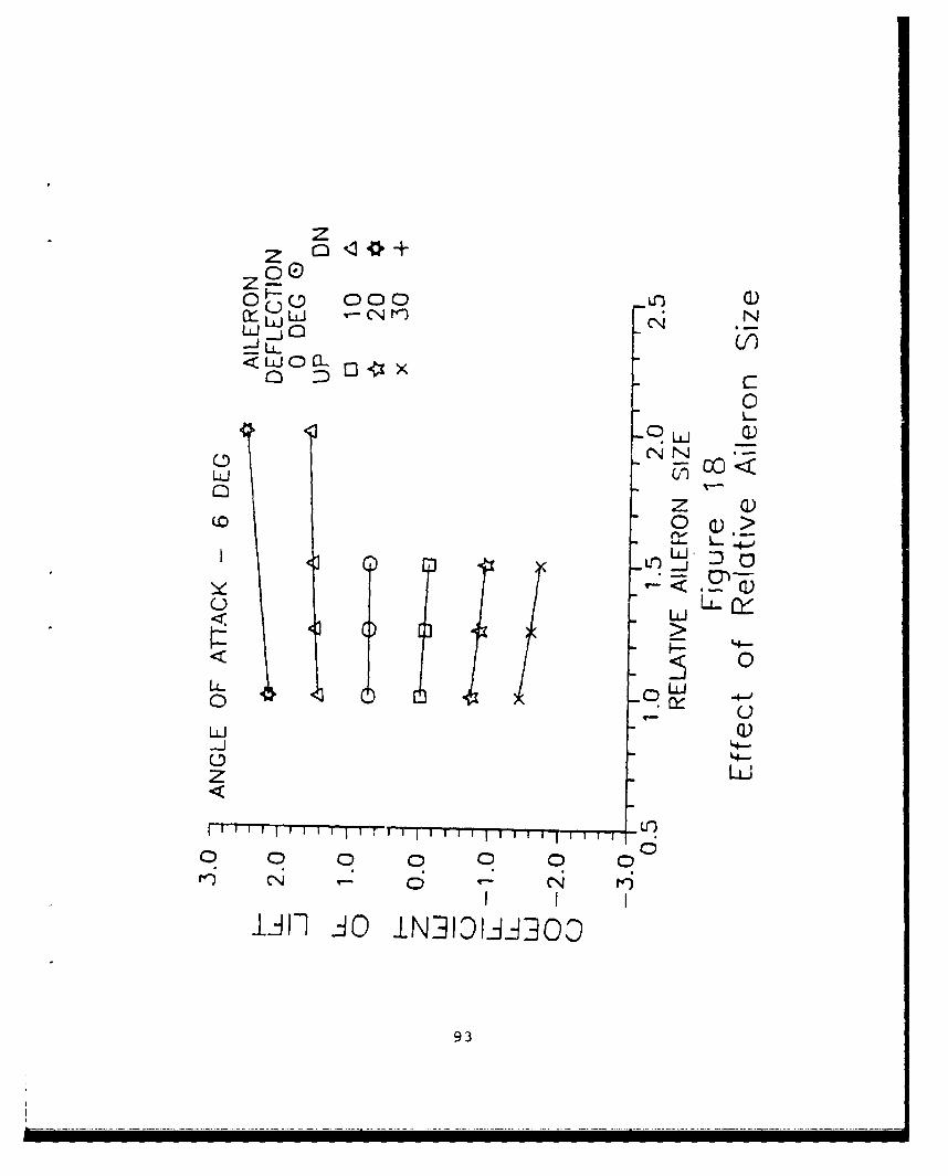
z
cLLJ LJ C-N'1
<LL _L 00x
uLJ
LO 0LnLL
LLLL
1 '4-
z LUj
I~ ~ ~ IT I I--- IT T-1-- - t
93

zz (
CD000 U) Q)or_ L.U L -N p) Ný
0 0
0.1± Q)0D-NwL i 7
C) z T - )
op )u .l Q)
1±4
<U 0)
0
z LiJ
o~06
A Iw JO IN]IOWA3Oo
94
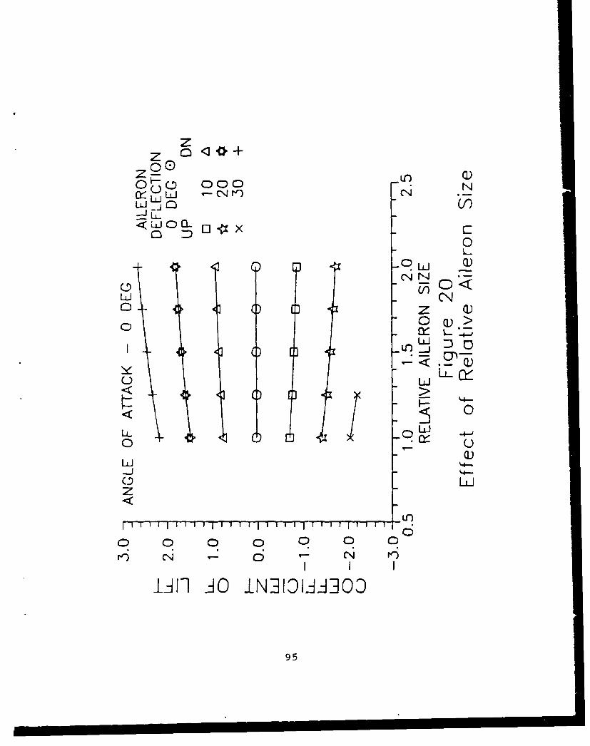
z
~LLLJ V).4~
0 D 0~L.
LLJ LL j0 z Q)
< Q
4L-
u ~LU
0 u
z
0000 0 00
Jill Aý O IN]I:Dl-i.iOD
95
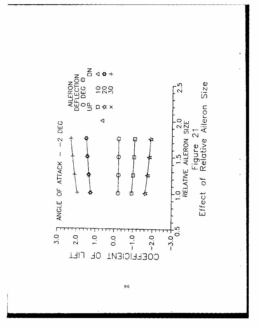
--------------
z
0~c 000o N
0 0 uJ Q
N0 >
'4-
'4-JouLi Q)
o 0
-LJI I IOi33.A0
96

zz
Oý3o 000 Q( )
(NJ LL
LUJ CN N
u -L
LU-0 C)-L
N-Z LIJ
I I ili l~l 'I I T-Tii U~')
o 0 C) 0 0 0 C
JillJO IN]I3liAO30
97

00C;
z
0
wy <M
Z < 0<0 L Q
N 0L-Q Yz E- Lo un L r3
zzt~z 0
0<0< Uý U
LL
0 0 0 0 00 LO0 U-) 0
Iii iý O iN313-OIii3O
98
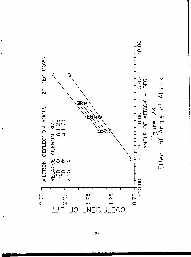
z0
o 9w U
Lil 0
zo00 <
00J 0W
UJ~ z
0 L0<
<U W
LO U- -L
c;4
Z ý AO NIO'3
0 99
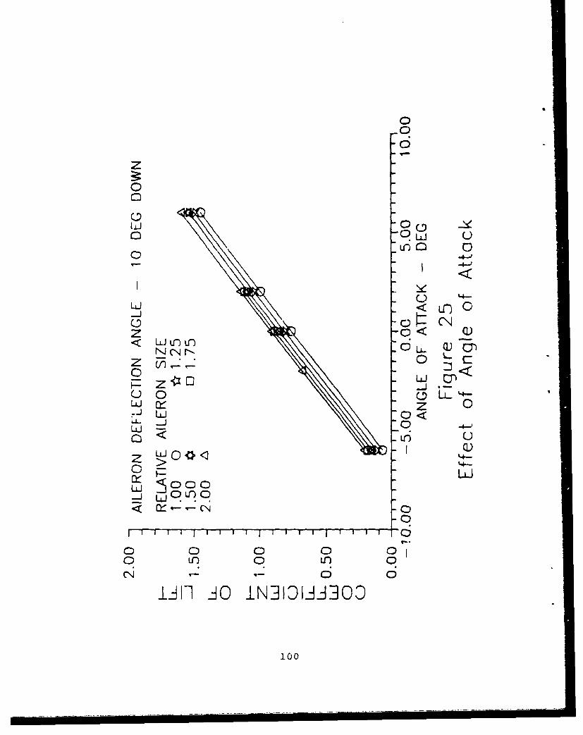
zS
00
0-
C0 0
z -0< Q)< LULu n 0 L..Q)
-J cu z 0ý1:u0 L 0
zJ - C0<0
B LU
r) C)
o L 0 < 0-
oL 0 U) 0 0
Ii i]OI]DifO
:;7:t1C0

0
00
0~ r~< LfJlC)Lr
0 L.
LU 0
Z 0< 0
zJ rý O 0
LL. _0
0 LI0
-LJ w0 )O
0 0 0 00- 0 U)01
I; 0
LW] 20 JOIN3]l"IOA A 10D
101

00
0
LAJ < 0
_0
0<
z 7 0LL0 Lz.J Z u0~
0A 0 WLU 0
-LJ 00<> 0c 0 ULLJ~~ 0)U
0 0 0
U00 CLiU00
102
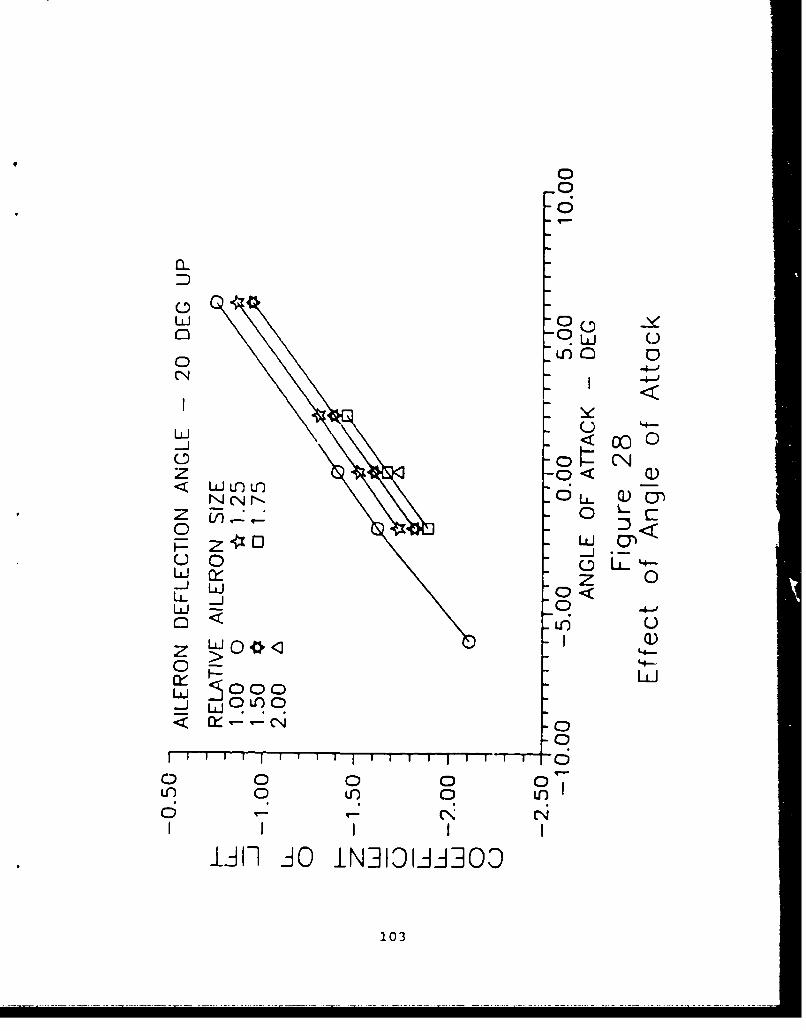
0
D
00
CN -4-d
LU
Z 0< Q)< Wuinu-)
N 0 L-Jy
-ZU Z 0)
ILL J 0 <0UJ -0
U~)QU
z W0*c0 0 <0>0 I- '4-
-J LUOU)
0
o o 0 0UL) 0 0U)
103

-0
U-)
0 0
o0 0 --0C j -4-d
-J) <0
<LI < cr) 0
0~ 4 LcL .
Lii- 0 :)
U i 0 0 (.DL )zLo* IJ) z 00J _L 4-
LL.LLJ~o
LLJlii > ii gil ii gi li
0 N C l 0 N- 0(- 4- 4- C- NN Ln
liii1 AO INBDWBOD10
104
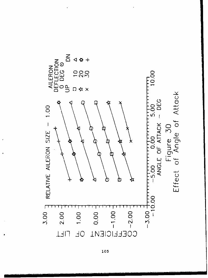
zz r)*
0000
C< Doco-
-- j U-<~ oi0C
-C)~
0 -
C-)N C -~
V) --0< Q)Cz LL.
0 0UJ L. N--
wj -j 0
< (:) 0f -0 Z -
-JL
-0
fii IjiI 11111 hf 1111 I
0 0 0 0 0 0 0a C)a 0 01
N C;0 '
IAH AýO iN]3ID-ii3OO
105
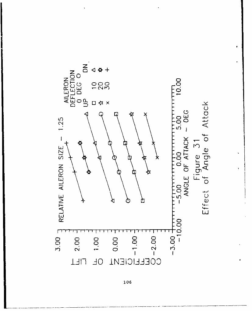
zV
z0~0 00
Lf) 0 JCN<
U'
LI) -0 Q)~
z 0 L.<
o Z
wJ LC)
Q)'4=
uliLUJ
0 0 0 0 0 000 0 0 0 0 0
Iii 1A1 O INDhOiJAiOO
106

z
0 0 0
LL LiUJ
0 owL) -4-LC) 00 4ý
4-)
NN 0
0< Q)
z ow <0
rHC-LJ L
-j -jU0UZ -00
o Z-
0
0 0 0 0 0 0 O0 0 0 0 0 0 0
Ný 0- rn)
IJ I] AO IN~hl~flOO30
107

00
z C0
0l-50- 000QwC)LuJ -CN t') C
0 Dx L-)
N _0 l )Ol -0< Q)~
0 d Y
0 C.0_0Z
> - IQ)< L4-
LI L-ii
000 0 0 000 00 0 0 0
rl) N 6 --
lii Aý O iN]3IOJA]OO
108

z~z0z3 00
o) 0L 0 )
<U 0kC0 0 x -
L)
U) 0C:-,
I 0)C-ý4<LUO
-0<
109

INITIAL DISTRIBUTION LIST
1. Defense Technical Information Center 2Cameron StationAlexandria, VA 22304-6145
2. Superintendent 2Library, Code 0142Naval Postgraduate SchoolMonterey, CA 93943-5002
3. Training Officer 5VP-31NAS, Moffett Field, CA 94035
4. Dr. Hank Smith 10VP-31NAS, Moffett Field, CA 94035
5. Chief Karl 1VP-31NAS, Moffett Field, CA 94035
6. Chairman IDepartment of Aeronautics and AstronauticsCode 67Naval Postgraduate SchoolMonterey, CA 93943
7. Prof. R. M. Howard 2Department of Aeronautics and AstronauticsCode 67HoNaval Postgraduate SchoolMonterey, CA 93943
8. LCDR C. A. Heard 2Pacific Missile Test CenterCode 3220Pt. Mugu, CA 93042-5000
9. Poole, D. 1VEDA Inc.300 ExplorationLexington Park, MD 20653
110
10. Smith, Kimberly K. 2Naval Air Test Center'WATD (RW-60)
* xent River, MD 20670
111