Embed Size (px)
Citation preview
'(NASA-CR-1 2030 vacuuii;D ST I LLATICalL ON ATI N74- 2 8 6 3 2 4O Summary Report for Phase 3,(General American Transportation Corp.)
aCSCL 0u6K UnclasCSCL 0'6K G3/05 42925
GENERAL AMERICAN TRANSPORTATION CORPORATION
GENERAL AMERICAN RESEARCH DIVISION7449 NORTH NATCHEZ AVE. NILES, IL 60648 312/647-9000
Reproduced by
NATIONAL TECHNICALINFORMATION SERVICE
US Department of CommerceSpringfield; VA. 22151
https://ntrs.nasa.gov/search.jsp?R=19740020519 2019-08-10T05:31:13+00:00Z
GENERAL AMERICAN RESEARCH DIVISION
GENERAL AMERICAN TRANSPORTATION CORPORATION
7449 NORTH NATCHEZ AVENUE
NILES, ILLINOIS 60648
VACUUM DISTILLATION/VAPOR FILTRATION
WATER RECOVERY
Summary Report for Phase III
Contract No. NAS 8-27467
GARD Project No. 1528
Prepared by
Chemical & Environmental Systems GroupEngineering Research Department
R. J. HoneggerR. B. NeverilG. A. Remus
Prepared for
Life Support and Environmental BranchGeorge C. Marshall Space Flight Center
National Aeronautics & Space AdministrationMarshall Space Flight Center, Alabama 35812
April 1974
GENERAL AMERICAN RESEARCH OVISON0
FOREWORD
This report summarizes the activities accomplished for preparing to
evaluate a Vacuum Distillation/Vapor Filtration water recovery system for
low-gravity testing. The report documents only preparatory tasks completed
or partially completed during the period 8 June 1973 to 16 January 1974; the
low-gravity tests have not yet been conducted in aircraft parabolic flights.
The work was conducted for the George C. Marshall Space Flight Center of
the National Aeronautics and Space Administration under Contract NAS 8-27467
by the General American Research Division of the General American Transpor-
tation Corporation.
The NASA Project Monitor was Mr. James L. Moses, Deputy Chief, Life
Support and Environmental Branch, Propulsion and Thermodynamics Division
(S&A-ASTN-P). Personnel in the Chemical and Environmental Systems Group
at GARD performed the activities under the direction of Mr. George A. Remus;
Mr. Robert J. Honegger served as Project Engineer and Mr. Robert B. Neveril
served as Design Engineer.
GENERAL AMERICAN RESEARCH DIVISiON
TABLE OF CONTENTS
Section Page
FOREWORD ii
LIST OF ILLUSTRATIONS iv
1 INTRODUCTION 1-1
1.1 Program Objectives 1-11.2 Program Summary 1-1
2 SYSTEM OPERATION 2-1
3 PREPARATIONS FOR LOW-GRAVITY TESTING 3-1
3.1 Analysis of Wave Motion During AircraftParabolic Flights 3-1
3.2 Evaporator Modifications 3-33.3 Structural Design of Support Frame 3-53.4 Cooling Unit 3-103.5 Component Changes and Check-Out Tests 3-12
3.5.1 Sludge Removal Pump 3-123.5.2 Drive Motor and Speed Reducer for
Evaporator Impeller 3-143.5.3 Oilless Vacuum Pump 3-14
3.6 Frame Fabrication and System Assembly 3-163.7 Present Status of Low-Gravity Test Preparations 3-21
3.7.1 System Assembly 3-253.7.2 Ground Perforamance Tests 3-263.7.3 Low-Gravity Test Plan 3-283.7.4 NASA/MSFC and GARD Preparations Coordi-
nation 3-28
GENERAL AMERICAN RESEARCH DVISON
iii
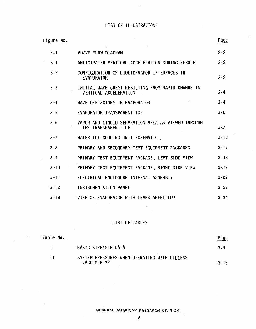
LIST OF ILLUSTRATIONS
Figure No. Page
2-1 VD/VF FLOW DIAGRAM 2-2
3-1 ANTICIPATED VERTICAL ACCELERATION DURING ZERO-G 3-2
3-2 CONFIGURATION OF LIQUID/VAPOR INTERFACES INEVAPORATOR 3-2
3-3 INITIAL WAVE CREST RESULTING FROM RAPID CHANGE INVERTICAL ACCELERATION 3-4
3-4 WAVE DEFLECTORS IN EVAPORATOR 3-4
3-5 EVAPORATOR TRANSPARENT TOP 3-6
3-6 VAPOR AND LIQUID SEPARATION AREA AS VIEWED THROUGHTHE TRANSPARENT TOP 3,7
3-7 WATER-ICE COOLING UNIT SCHEMATIC 3-13
3-8 PRIMARY AND SECONDARY TEST EQUIPMENT PACKAGES 3-17
3-9 PRIMARY TEST EQUIPMENT PACKAGE, LEFT SIDE VIEW 3.,18
3-10 PRIMARY TEST EQUIPMENT PACKAGE, RIGHT SIDE VIEW 319
3-11 ELECTRICAL ENCLOSURE INTERNAL ASSEMBLY 3-22
3-12 INSTRUMENTATION'PANEL 3-23
3-13 VIEW OF EVAPORATOR WITH TRANSPARENT TOP 3-24
LIST OF TABLES
Table No. Page
I BASIC STRENGTH DATA 3-9
II SYSTEM PRESSURES WHEN OPERATING WITH OILLESSVACUUM PUMP 3-15
GENERAL AMERICAN RESEARCH OIVtJSON
iv
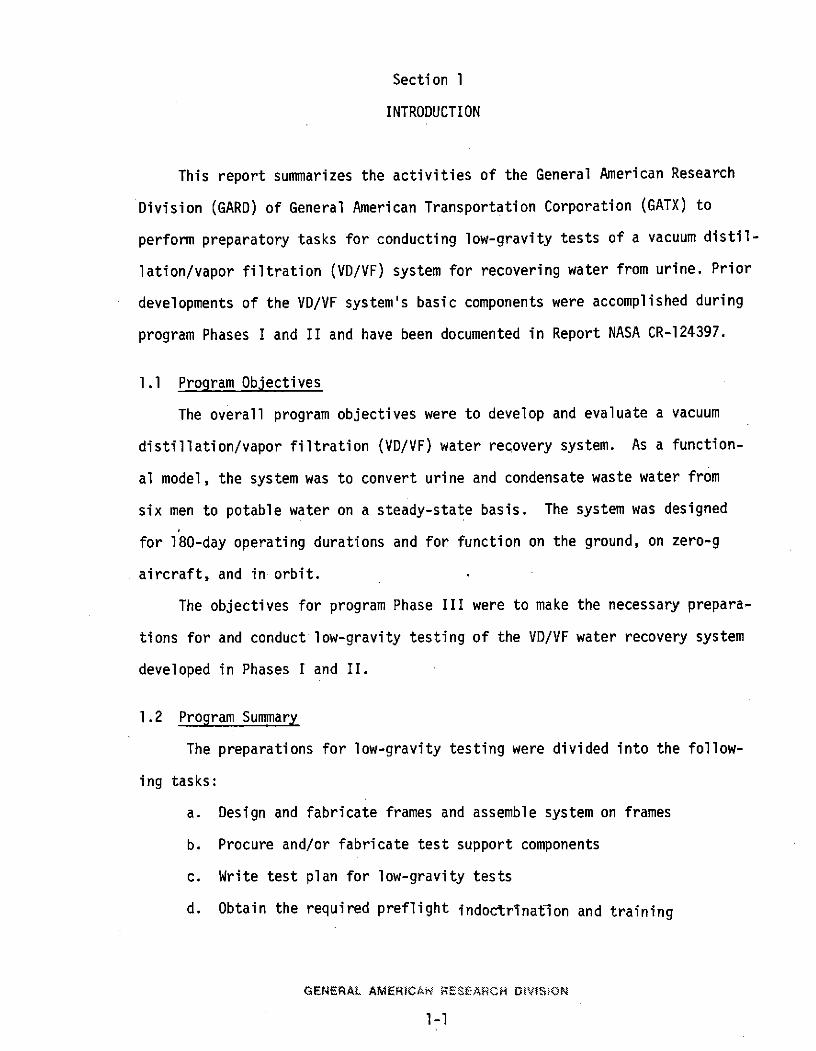
Section 1
INTRODUCTION
This report summarizes the activities of the General American Research
Division (GARD) of General American Transportation Corporation (GATX) to
perform preparatory tasks for conducting low-gravity tests of a vacuum distil-
lation/vapor filtration (VD/VF) system for recovering water from urine. Prior
developments of the VD/VF system's basic components were accomplished during
program Phases I and II and have been documented in Report NASA CR-124397.
1.1 Program Objectives
The overall program objectives were to develop and evaluate a vacuum
distillation/vapor filtration (VD/VF) water recovery system. As a function-
al model, the system was to convert urine and condensate waste water from
six men to potable water on a steady-state basis. The system was designed
for 180-day operating durations and for function on the ground, on zero-g
aircraft, and in orbit.
The objectives for program Phase III were to make the necessary prepara-
tions for and conduct low-gravity testing of the VD/VF water recovery system
developed in Phases I and II.
1.2 Program Summary
The preparations for low-gravity testing were divided into the follow-
ing tasks:
a. Design and fabricate frames and assemble system on frames
b. Procure and/or fabricate test support components
c. Write test plan for low-gravity tests
d. Obtain the required preflight indoctrination and training
GENERAL AMERICAN RESEARCH DIVISION
1-1
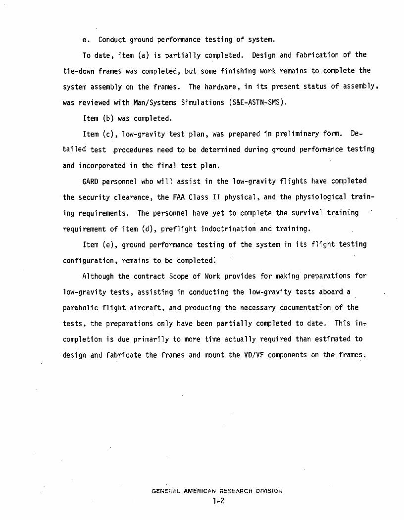
e. Conduct ground performance testing of system.
To date, item (a) is partially completed. Design and fabrication of the
tie-down frames was completed, but some finishing work remains to complete the
system assembly on the frames. The hardware, in its present status of assembly,
was reviewed with Man/Systems Simulations (S&E-ASTN-SMS).
Item (b) was completed.
Item (c), low-gravity test plan, was prepared in preliminary form. De.
tailed test procedures need to be determined during ground performance testing
and incorporated in the final test plan.
GARD personnel who will assist in the low-gravity flights have completed
the security clearance, the FAA Class II physical, and the physiological train-
ing requirements. The personnel have yet to complete the survival training
requirement of item (d), preflight indoctrination and training.
Item (e), ground performance testing of the system in its flight testing
configuration, remains to be completed.
Although the contract Scope of Work provides for making preparations for
low-gravity tests, assisting in conducting the low-gravity tests aboard a
parabolic flight aircraft, and producing the necessary documentation of the
tests, the preparations only have been partially completed to date. This inr
completion is due primarily to more time actually required than estimated to
design and fabricate the frames and mount the VD/VF components on the frames.
GENERAL AMERICAN RESEARCH DMVISiON
1,2
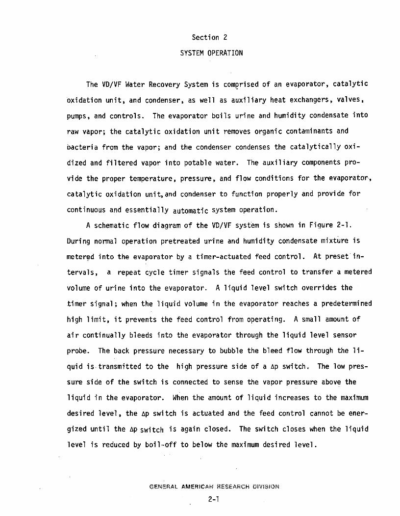
Section 2
SYSTEM OPERATION
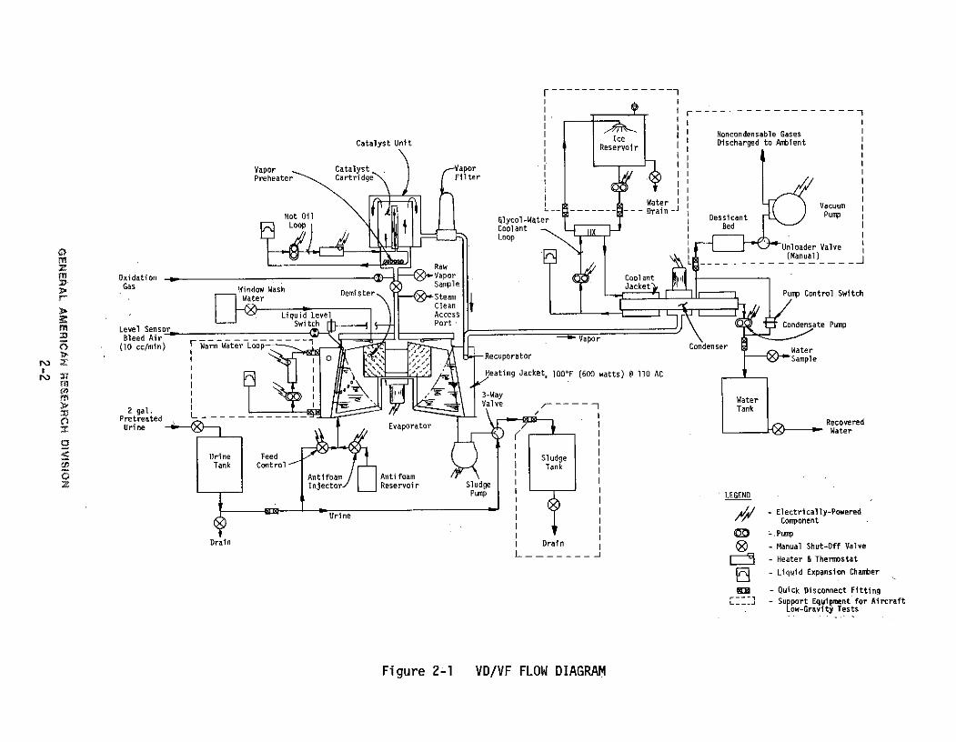
The VD/VF Water Recovery System is comprised of an evaporator, catalytic
oxidation unit, and condenser, as well as auxiliary heat exchangers, valves,
pumps, and controls. The evaporator boils urine and humidity condensate into
raw vapor; the catalytic oxidation unit removes organic contaminants and
bacteria from the vapor; and the condenser condenses the catalytically oxi-
dized and filtered vapor into potable water. The auxiliary components pro-
vide the proper temperature, pressure, and flow conditions for the evaporator,
catalytic oxidation unit,and condenser to function properly and provide for
continuous and essentially automatic system operation.
A schematic flow diagram of the VD/VF system is shown in Figure 2-1.
During normal operation pretreated urine and humidity condensate mixture is
metered into the evaporator by a timer-actuated feed control. At preset in-
tervals, a repeat cycle timer signals the feed control to transfer a metered
volume of urine into the evaporator. A liquid level switch overrides the
timer signal; when the liquid volume in the evaporator reaches a predetermined
high limit, it prevents the feed control from operating. A small amount of
air continually bleeds into the evaporator through the liquid level sensor
probe. The back pressure necessary to bubble the bleed flow through the li-
quid is transmitted to the high pressure side of a Ap switch. The low pres-
sure side of the switch is connected to sense the vapor pressure above the
liquid in the evaporator. When the amount of liquid increases to the maximum
desired level, the Ap switch is actuated and the feed control cannot be ener-
gized until the Ap switch is again closed. The switch closes when the liquid
level is reduced by boil-off to below the maximum desired level.
GENERAL AMERICAN RESEARCH DIVI~SON
2-1
1I --II
SI Noncondensable GasesCatalyst Unit Res oir I Discharged to Ambient
Vapor Catalyst -Vapor IPreheater Cartridge Il Filter
Water Vacuum-- - Drain -Pump
Hot Oil lycol-Water TDessicant PumpLoop Coolant Bed
-a LooUnloader Valve(Manual)
z Raw .
Oxidation Vapor CoolantGas Sample Jacket
SWdow Wash Demister Pump Control Switch
Clean- Liquid Level s
Level Senwitch Port Condensate Pump
2 Bleed Air VaporO (10 cc/min) oWam Water Loop Condenser
S-Recuperator Sample
u Heating Jacket, 1000F (600 watts) @ 110 AC
S3-WayValve Wtr
Prtaed L RecoveredUrine Evaporator /er
Water
Urine Feed SludgeTank Control Tank
C:Antifoam / I I AntifoamInjector _ Reservoir Sludge
Pump LEGEND
I Urine - Electrically-PoweredComponent
- PumpDrain Dratn - Manual Shut-Off Valve
L - - Heater & Thermostat
a - Liquid Expansion Chaber
DMR - Quick Disconnect Fitting- Support Equipment for Aircraft
Low-Gravity Tests
Figure 2-1 VD/VF FLOW DIAGRAM
The bleed air entering through the level sensor probe prevents fouling
and clogging, and eventually reacts in the catalytic oxidizer with volatiles
generated during urine distillation.
A rotating impeller inside the evaporator provides centrifugal accelera-
tion for low-gravity separation of liquid and vapor and provides the desired
velocity of liquid along the heat transfer surface. The impeller also has
a de-misting mesh to coalesce fine droplets which escape the main body of
liquid during boiling. The impeller rotates about its vertical axis; the
vapor flows radially inward through the de-mister mesh and then-axially through
the outlet-tube which is concentric with the centerline of rotation. The
centrifugal effect provides sufficient force to constrain the main body of
liquid against the wall.
Heat input is provided from a heat transport loop to a liquid jacket
which then transfers heat across the evaporator wall to the urine. During
low-gravity testing the heat will be supplied by electric heating elements
(115-volt, 400 Hz) and maximum loop temperature will be limited by a thermo-
static switch.
The raw, de-misted vapor leaves the evaporator, is mixed with a small
measured quantity of oxygen, and flows to the catalytic oxidation unit where
the mixture is heated to approximately 300 0F. Heat is supplied by an elec-
tric heater to a hot liquid loop which in turn heats the vapor and catalyst
bed. The 3000 F vapor and oxygen flow through a catalyst bed where the vapor
is sterilized and trace organic contaminants are oxidized. A membrane filter
serves as a sterilization back-up to the hot catalyst bed and filters par-
ticulates from the vapor stream.
Vapor flow from the catalytic oxidation unit passes through a recuperator
before entering the condenser. The recuperator, a coiled tube submerged
GENERAL AMERICAN RESEARCH DIVISiON
2-3
in the evaporator heating jacket, transfers part of the heat from the vapor
to the heating jacket liquid, thus reducing the amount of heat to be removed
in the condenser.
Vapor flows to the condenser, enters near the center, and is distributed
near the center of the rotating impeller by an inlet manifold. Vapors are
then constrained to flow radially outward between one of two identical con-
densing surfaces and the rotating impeller plate. The vapor flows radially
out and along the heat transfer surface with condensation occurring as it
contacts the cool surface. Flexible wiper blades, attached to the rotating
impeller, continually wipe the smooth condensing surface and collect the con-
densation droplets along the wipers. The rotating impeller and wiper blades
impart a centrifugal force to the condensate to direct it radially outward
to the outer housing of the condenser. Any vapor which is not condensed dur-
ing the first pass along the condensing surface flows around the impeller
plateand then radially inward along the opposite cool surface to effect com-
plete condensation. Noncondensable gases are removed at the center of the
condenser on the side opposite the vapor inlet.
The condensate within the condenser collects along the inside surface
of the housing; a timer (the same timer which is part of the urine feed con-
trol) periodically actuates a pump to transfer the condensate from low pres-
sure to storage at ambient pressure. The pump is started by the timer and
continues to operate until all the condensate is removed and the pump dis-
charge pressure drops; this drop is sensed by a pressure switch located at
the pump discharge and actuation of the switch shuts off the pump.
Identical coolant jackets located on each side of the condenser have
radial flow guides to direct the coolant over the entire heat transfer sur-
face. The flow guides not only direct coolant flow but also.give this surface
GENERAL AMERICAN RESEARCH DIVISON
2-4
the structural rigidity needed to remain flat when the internal pressure is
reduced to the 10-20 mm Hg absolute operating level.
A recirculating coolant loop operating between the condenser and a heat
sink supplies the required coolant flow and temperature level at the conden-
ser. For the low-gravity tests, the heat sink is a reservoir of ice which
melts to water when it receives the heat of condensation via the coolant loop.
The ice is located within a cooling unit which sprays the cooling water over
the ice and contains the water generated for draining at the conclusion of a
test run.
The noncondensable gases removed from the condenser are drawn through
a desiccant bed for partial moisture removal and then compressed by an oilless
vacuum pump to atmospheric pressure and discharged into the cabin.
At various times during operation of the system, the antifoam injector
is operated,as required, to maintain the proper antifoam concentration in the
evaporator. The frequency of antifoam injector operation depends on the dis-
tillation rate and the ratio of urine to humidity condensate being fed to the
evaporator. The injector is electrically operated but requires manual sig-
nalling by a momentary contact switch.
When the sludge, accumulating in the evaporator, reaches a predetermined
concentration, the distillation process is manually shut down. The evaporator
vapor discharge valve is closed (manually), and the sludge line 3-way valve
is positioned (manually) to connect the sludge pump to the sludge collection
tank. The sludge pump and evaporator impeller are then operated to pump
sludge from the evaporator to the sludge tank. When the evaporator is emptied,
the sludge pump is shut off, the 3-way valve is positioned to accept urine,
the pump operational mode is reversed, and the evaporator is filled with fresh
urine. As an additional option, after emptying the evaporator of sludge, and,
prior to refilling with fresh urine, steam can be fed into the vapor discharge
GENERAL. AMERICAN RESEARCH DIVISION
2-5
duct to further clean the internal evaporator surfaces. The impeller and
sludge pump would continue to operate during the steam cleaning process.
GENF~AL AMERICAN RESEARCH OIVIS ON
2-6
Section 3
PREPARATIONS FOR LOW-GRAVITY TESTING
To test the VD/VF system aboard a zero-g aircraft, the system must
be contained in a supporting framework conforming to prescribed struc-
tural requirements and interfacing dimensions with the aircraft. Also,
to obtain the desired test data, a transparent top over the entire evaporator
is required in place of the metal top with sightglasses, and to make the
system totally independent of the aircraft (excepting required electrical
power), a cooling unit which receives the thermal heat rejected from the
system should be installed as an integral part of the test equipment.
3.1 Analysis of Wave Motion During Aircraft Parabolic Flights
The rotating impeller inside the evaporator produces a continuous cen-
trifugal acceleration of the liquid whose magnitud3 varies with the square
of the angular speed. Based on information from the WPAFB Zero-G Test Office,
the vertical acceleration (perpendicular to the aircraft floor) varies between
zero and 2-g while lateral and longitudinal accelerations are essentially
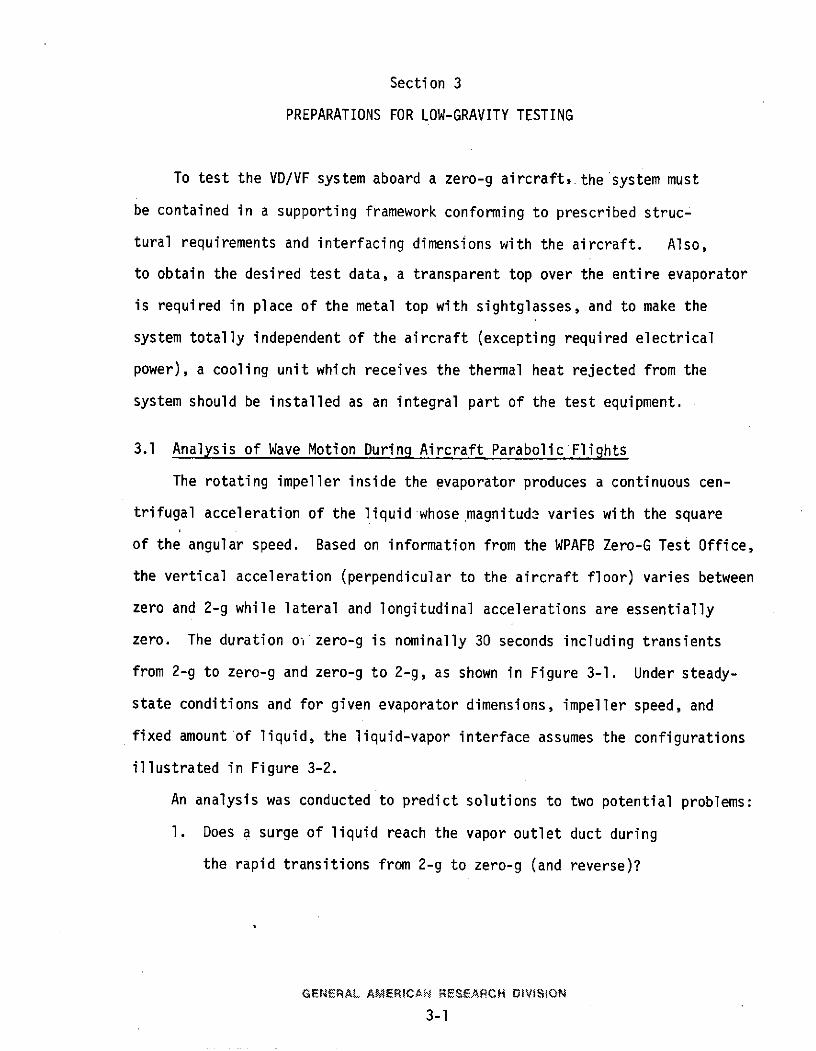
zero. The duration o- zero-g is nominally 30 seconds including transients
from 2-g to zero-g and zero-g to 2-g, as shown in Figure 3-1. Under steady-
state conditions and for given evaporator dimensions, impeller speed, and
fixed amount'of liquid, the liquid-vapor interface assumes the configurations
illustrated in Figure 3-2.
An analysis was conducted to predict solutions to two potential problems:
1. Does a surge of liquid reach the vapor outlet duct during
the rapid transitions from 2-g to zero-g (and reverse)?
GENERAL AMERICAN RESEARCH OVISION
3-1
VerticalAcceleration(g) 2 - --
1-
0.1 Time (sec)
2-3- 4-6 21 2-4
30
Figure 3-1 ANTICIPATED VERTICAL ACCELERATION DURING ZERO-G
Vapor Discharge Duct
Vertical Acceleration:Vapor Space
. Zero
i 1-gLiquid
2-g
Heat Input Surface
Figure 3-2 CONFIGURATION OF LIQUID/VAPOR INTERFACES IN EVAPORATOR
GENERAL AMERICAN RESEARCH DIVISION
3-2
2. After the aircraft is decelerated to zero-g vertical,
are waves damped enough for the liquid motion in the
vertical direction to be essentially zero (as desired
to simulate sustained zero-g)?
The results of the analysis are summarized as follows:
The initial wave crest accompanying a rapid transition from 2-g to
zero-g (and reverse) will be approximately the same height as the body of
liquid just prior to the transition in acceleration. Figure 3-3 shows the
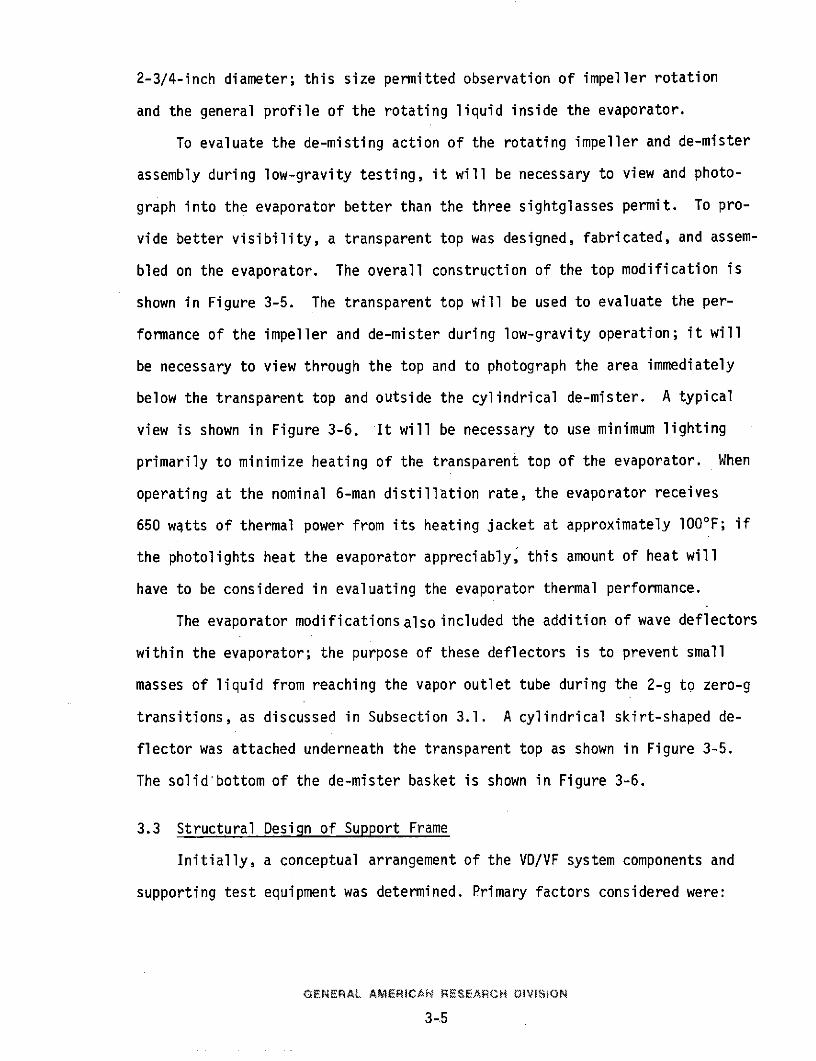
2-g to zero-g liquid movement. A solution to this potential problem is to
incorporate wave deflectors at strategic locations inside the evaporator,
to prevent waves and/or spray from reaching the vapor outlet duct, as shown
in Figure 3-4. A solid plate under the de-mister basket will aid in deflect-
ing waves set up during the 2-g pull-out. A cylindrical deflector attached
to the under side of the transparent top will aid in deflecting.waves set up
during the 2-g to zero-g transition.
The primary period of oscillation of vertical motion along the heat in-
put wall was calculated to be 0.38 second. During the 4- to 6-second tran-
sition time in which the aircraft establishes zero-g there could be between
8 and 16 complete oscillations if the liquid were ideally nonviscous. These
oscillations will probably die down by dissipation (viscous effects, breaking
of the liquid surface) in two or three cycles. Therefore, it is predicted
that liquid will cover the heat input wall for a major portion of the zero-g
test time in a behavior similar to what would be expected in sustained zero-g.
3.2 Evaporator Modifications
The evaporator assembly, as constructed and tested in program phases
I and II, had three sightglasses in the top cover. Each sightglass was
GENERAL AMERICAN RESEARCH OIVISioN
3-3
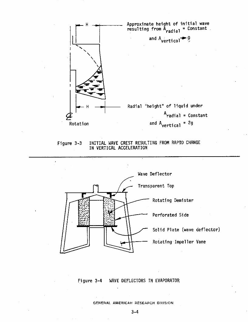
SH Approximate height of initial waveresulting from Aradial = Constant
and A **0and Avertical-
H Radial "height" of liquid under
Aradial = Constant
Rotation and Avertical = 2g
Figure 3-3 INITIAL WAVE CREST RESULTING FROM RAPD CHANGEIN VERTICAL ACCELERATION
Wave Deflector
Transparent Top
- Rotating Demister
Perforated Side
Solid Plate (wave deflector)
Rotating Impeller Vane
Figure 3-4 WAVE DEFLECTORS IN EVAPORATOR
GENERAL AMERICAN RESEARCH DOVIS$ON
3-4
2-3/4-inch diameter; this size permitted observation of impeller rotation
and the general profile of the rotating liquid inside the evaporator.
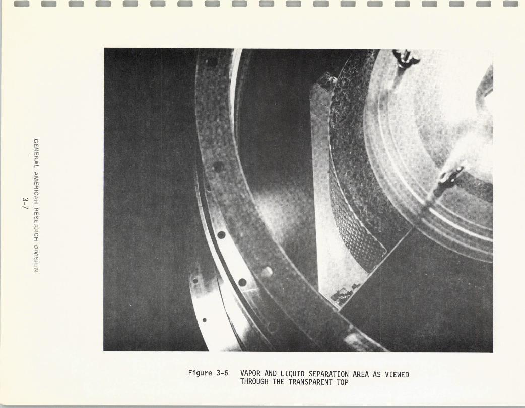
To evaluate the de-misting action of the rotating impeller and de-mister
assembly during low-gravity testing, it will be necessary to view and photo-
graph into the evaporator better than the three sightglasses permit. To pro-
vide better visibility, a transparent top was designed, fabricated, and assem-
bled on the evaporator. The overall construction of the top modification is
shown in Figure 3-5. The transparent top will be used to evaluate the per-
formance of the impeller and de-mister during low-gravity operation; it will
be necessary to view through the top and to photograph the area immediately
below the transparent top and outside the cylindrical de-mister. A typical
view is shown in Figure 3-6. It will be necessary to use minimum lighting
primarily to minimize heating of the transparent top of the evaporator. When
operating at the nominal 6-man distillation rate, the evaporator receives
650 watts of thermal power from its heating jacket at approximately 1000F; if
the photolights heat the evaporator appreciably, this amount of heat will
have to be considered in evaluating the evaporator thermal performance.
The evaporator modificationsalso included the addition of wave deflectors
within the evaporator; the purpose of these deflectors is to prevent small
masses of liquid from reaching the vapor outlet tube during the 2-g to zero-g
transitions, as discussed in Subsection 3.1. A cylindrical skirt-shaped de-
flector was attached underneath the transparent top as shown in Figure 3-5.
The solid'bottom of the de-mister basket is shown in Figure 3-6.
3.3 Structural Design of Support Frame
Initially, a conceptual arrangement of the VD/VF system components and
supporting test equipment was determined. Primary factors considered were:
GENERAL AMERICAN RESEARCH DVISiON
3-5

IleI
0
r
Figure 3-5 EVAPORATOR TRANSPARENT TOP
......... ..: ::
-------- -----
C
Figure 3-6 VAPOR AND LIQUID SEPARATION AREA AS VIEWEDTHROUGH THE TRANSPARENT TOP
flll
2,r
2,a
2,I,~,
C,,
Figure 3-6 VAPOR AND LIQUID SEPARATION AREA AS VIEWEDTHROUGH THE TRANSPARENT TOP
1. Open area above evaporator for visibility into trans-
parent top
2. Access to major components that require adjustments or
servicing during testing of the system
3. Ease of access to electrical components (drive motors,
pumps, heating cartridges) for ready replacement, if
required.
The most suitable arrangement was to mount all test equipment and test support
components in two separate frames. Each frame could be individually handled
and tied-down in the aircraft. Fluid connections between the frames could be
made through flexible lines and quick-disconnect fittings. The evaporator,
condenser, catalyst unit, and controls and instrumentation are mounted in the
main package; the secondary package contains tanks, supporting vacuum pump,
cooling unit, etc.
After conceptual frame design, structural analyses of anticipated criti-
cal areas in the frame were performed. The structural requirements were those
listed in the "Unofficial Syllabus for Zero-G Test Programs", prepared by the
WPAFB Zero-G Office.
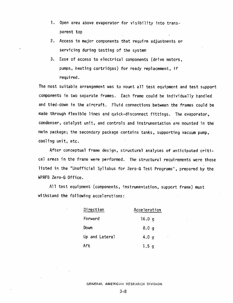
All test equipment (components, instrumentation, support frame) must
withstand the following accelerations:
Direction Acceleration
Forward 16.0 g
Down 8.0 g
Up and Lateral 4.0 g
Aft 1.5 g
GENERAL AMERICAN RESEARCH DIVISION
3-8
The test equipment may be stressed to ultimate material strength and allow
permanent deformation, but not fracture, while accommodating the above accel-
erations.
It was assumed that the requirements to withstand the above accelerations
already include a factor of safety; therefore, no additional factor was consi-
dered. The structural design criteria were: calculated stress < allowable
ultimate strength.
The material selected for basic frame members was extruded angles and
channels of aluminum alloy 6061-T6. Joining was by welding with AA 4043 filler
alloy; there is no heat treatment after welding.
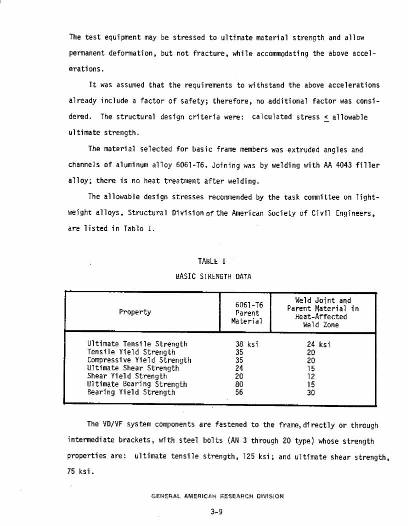
The allowable design stresses recommended by the task committee on light-
weight alloys, Structural Division of the American Society of Civil Engineers,
are listed in Table I.
TABLE I
BASIC STRENGTH DATA
Weld Joint andProperty 6061-T6 Parent Material in
Property Parent Heat-AffectedMaterial Weld Zone
Ultimate Tensile Strength 38 ksi 24 ksiTensile Yield Strength 35 20Compressive Yield Strength 35 20Ultimate Shear Strength 24 15Shear Yield Strength 20 12Ultimate Bearing Strength 80 15Bearing Yield Strength 56 30
The VD/VF system components are fastened to the frame,directly or through
intermediate brackets, with steel bolts (AN 3 through 20 type) whose strength
properties are: ultimate tensile strength, 125 ksi; and ultimate shear strength,
75 ksi.
GENERAL AMERICAN RESEARCH DIVISiON
3-9
Calculations were performed for the anticipated critical stress areas
only; these areas were for the primary frame members to withstand 16-g for-
ward and 4-g lateral acceleration (independently). The primary vertical sup-
port members are loaded in flexure by the forward and the lateral accelerations
and are loaded in direct tension or compression by the down and the up accel-
erations. Because the load-carrying capacity of a frame member is less under
flexure loading, the highest (critical) stresses result from forward and lat,
eral accelerations.
The structural calculations were submitted to S&E-ASTN"SMS for review
and were approved.
3.4 Cooling Unit
During ground testing of the VD/VF system in Phase II, a commercial
vapor-cycle refrigeration unit was used as the system heat sink. This unit
is unsatisfactory for zero-g operation, and the test aircraft does not have
a readily available refrigeration system onboard. To support the aircraft
tests, a cooling unit was designed, assembled, and installed in the secon-
dary frame.
The design performance requirements of the cooling unit are:
Heat Load 3000 Btu/hrOperational Time 4 hoursGlycol Coolant Flow Rate 1-1/2 gpmGlycol Coolant TemperatureLeaving Coolant Unit 38 + 40 F
Two methods of providing the required cooling, sublimation of dry ice
(solid carbon dioxide) and the melting of water-ice, were considered. The
water-ice method was chosen because it provides the following advantages:
1. The problem of coolant freeze-up is eliminated because
the coldest part of the unit is 320F with water-ice as
contrasted to -110°F with solid carbon dioxide.
GENERAL. AMERICA RESEARCH DIVISiON
3-10
2. There is no potentially undesirable contamination of the
aircraft cabin; the ice melts into water which is con-
tained in the cooling unit and drained at the end of the
flight. Solid carbon dioxide sublimes into gaseous car-
bon dioxide and could entail a large increase in volume
or pressure in the unit or within the aircraft if not
properly vented. The gaseous carbon dioxide could be
vented overboard but precautions would be required to
avoid freeze-up or clogging of the overboard vent regula-
tor.
3. Less insulation is required with a water-ice heat sink
because the temperature difference between ambient and
the heat sink is much lower with ice than with solid car-
bon dioxide.
4. The glycol coolant for the condenser is contained within
a sealed unbroken loop. The desired arrangement of the
components within two supporting frames has the conden-
ser located in the primary frame and the cooling unit
located in a secondary frame. With the ice-type cooling
unit the uncoupling of lines between packages may con-
veniently be the cold water lines at disconnect fittings,
rather than glycol coolant, thus avoiding potential
spillage of coolant during installation or removal aboard
the aircraft.
5. It is anticipated that the availability of ice will be
better than for solid carbon dioxide. It will be necessary
to reload the cooling unit prior to each daily test flight.
GENERAL AM ERICN RESE-ARCH DIVISiON
311
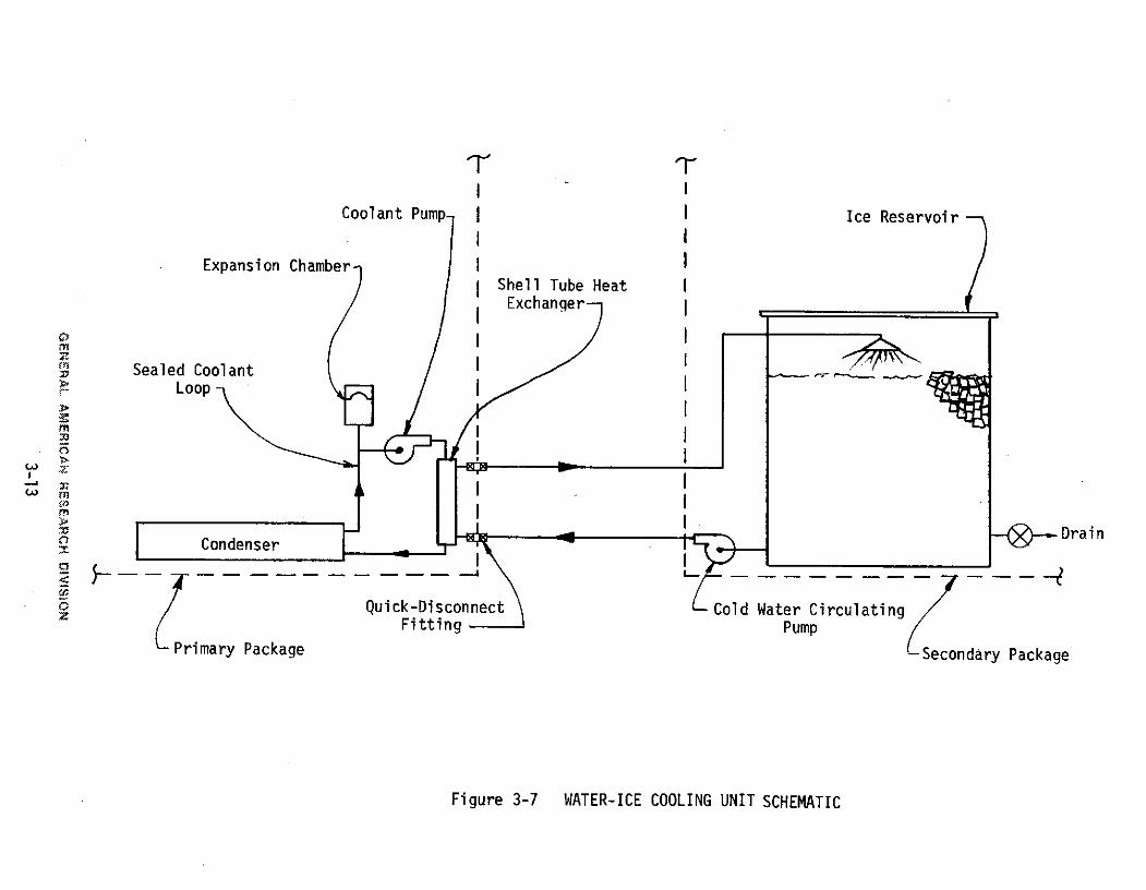
The cooling unit is shown schematically in Figure 3-7. The ice reser-
voir is a 60-gallon drum with removable cover. Prior to each daily low-
gravity flight, the reservoir will be drained of water (the melted ice from
the previous run) and loaded with 200 pounds of ice cubes. Approximately
20 pounds of ice will melt during the initial cooldown from ambient tempera-
ture to the 350-40°F operating range temperature. The condenser heat load
will be 3000 Btu/hour and heat input through the insulation and mounting is
estimated to be 1000 Btu/hour. One-hundred-ten (110) pounds of ice will melt
while receiving the 4000 Btu/hour during four hours of operation. The re-
maining 70 pounds of ice provides a safety margin for maintaining adequate
cooling over a four-hour period.
3.5 Component Changes and Check-Out Tests
During the course of preparations for low-gravity testing, three com-
ponents were altered from or added to the configuration of the VD/VF system
tested in Phase II. These were the sludge removal pump, evaporator drive
unit, and vacuum pump.
3.5.1 Sludge Removal Pump
The evaporator impeller produces a pumping action on the liquid inside
the evaporator. Although liquid head produced was sufficient to empty the
evaporator into a nearby container, it was not sufficient to pump the sludge
through piping, shut-off valves, and into a closed tank as desired in the
low-gravity test installation.
A high-capacity peristaltic pump, Masterflex Model 7019 with 3/8-inch ID
by 5/8-inch OD Tygon flexible tube and operable up to 650 rpm, was evaluated
for use as a dual-function sludge removal and urine fill pump. A bench check-
out test, simulating pressure levels involved when emptying the vacuum evaporator
GENERAL AMERICAN RESEARCH OIVISION
3-12
I -ICoolant Pump I I Ice Reservoir
Expansion Chamber IShell Tube HeatExchanger
Sealed Coolant> Loop
I
S-Drain0Condenser
Quick-Disconnect Cold Water CirculatingFitting Pump
Primary Package -Secondary Package
Figure 3-7 WATER-ICE COOLING UNIT SCHEMATIC
to a sludge tank,was conducted with a pumping rate of 0.4 gpm of water at a
pump speed of 280 rpm; the water was pumped from a vacuum jar at 50 mm Hg
aboslute to a container at atmospheric pressure.
By reversing the direction of the rotation, the pump was also operated
in the opposite mode, simulating the transfer of urine into the evaporator.
Since the Masterflex High Capacity peristaltic pump was found suitable
for the dual functions of sludge removal and initial urine fill, it was
coupled to a 1/10-HP, 280-rpm gear motor for assembly into the VD/VF system.
3.5.2 Drive Motor and Speed Reducer for Evaporator Impeller
The evaporator assembly, as developed and tested in phases I and II,
utilized a brushless-dc motor for the impeller drive. A 3-stage gearbox
with steel spur gears reduced the motor output speed from 6000 rpm to 100 rpm
(the impeller operating speed). Although this drive assembly nominally did
the job, there were some problems with gear wear and lubrication, and the
spur gears are inherently noisy.
During the check-out tests of the sludge pump (described in Subsection
3.5.1), it was observed that the gear motor selected for the pump would be
more suitable than the motor presently used for the evaporator impeller
drive. This motor was installed on the evaporator and bench checkout tested.
A reduction of noise was realized (as desired); also, the latter gear motor
has a 1/10-HP rating as contrasted to the approximately 1/30,HP rating of
the previous motor. Because of the higher load capacity, it is anticipated
that the gear wear problems will be lessened.
3.5.3 Oilless Vacuum Pump
A vacuum source is required to initially reduce the VD/VF system pressure
to the correct operational level and then to remove noncondensable gases from
GENERAL AMERICAN RESEARCH OiVI&SON
3-14
the system. During phase II performance tests, a conventional oil-filled
vacuum pump was used. A dry ice and acetone-cooled freeze-out foretrap was
used to reduce the specific humidity of the noncondensable gas stream enter-
ing the pump.
For the aircraft low-gravity tests an oilless pump is preferred because
the pump discharge will not contaminate the fuselage with oil and oil vapor.
An oilless vacuum pump and desiccant adsorbent bed was connected to the
VD/VF system in place of the oil-filled pump and freeze-out foretrap. The
oilless pump is actually two units with two diaphragm heads per unit inter-
connected to function as a vacuum pump with a single intake port and a single
discharge port.
The oilless vacuum pump was capable of removing noncondensable gases
from the condenser and maintaining the desired level of absolute pressure in
the system. (The system pressures are affected by both noncondensable flow
rate'and vapor flow rate through the system.) Pertinent pressure data for
three rates of oxygen feed to the catalyst are summarized in Table II.
TABLE II
SYSTEM PRESSURES WHEN OPERATING WITH OILLESS VACUUM PUMP
Pressure (mm Hg)
Oxygen Feed Recovery Evaporator Condenser Catalyst Filter(cc/min, STP) Rateabs. abs. Ap.p
(#/hr) abs. abs. p p
400 2.3 23 15 1.6 6.2
600 2.3 24 17 1.5 6.0
700 2.5 28 18 1.7 7.0
GENERAL AMERICAN RESEAPCH DIVISiON
3-15
The above tests and results indicated the oilless vacuum pump will be satis-
factory for the aircraft low-gravity tests.
3.6 Frame Fabrication and System Assembly
Two structural tie-down frames, a primary frame for mounting the basic
VD/VF system and controls and instrumentation and a secondary.frame for
mounting test support equipment, were fabricated. The two frames, as con-
structed, support all equipment,except cameras and lighting, for conducting
low-gravity testing.
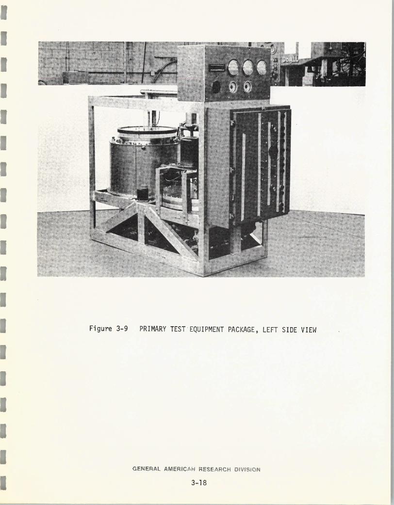
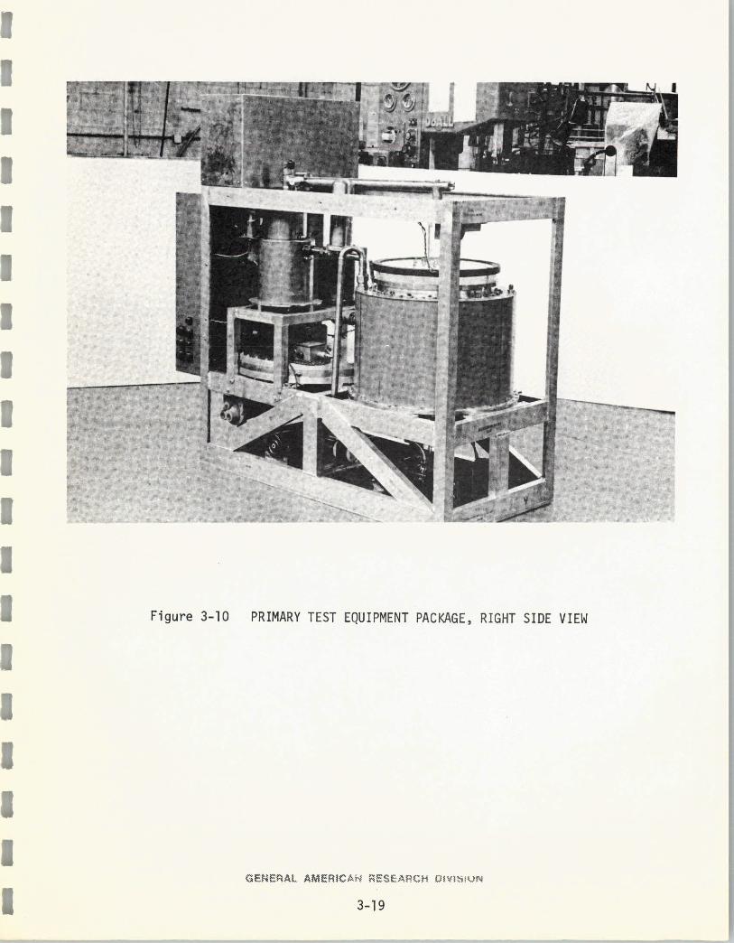
The support frames and mounted components are shown in their anticipated
orientation in Figure 3-8. Figures 3-9 and 3-10 show side views of the main
frame assembly. Each frame is constructed of structural aluminum extrusions
(primarily 3-inch channel) and formed sheet bracketry. The basic construction
is heliarc welding; threaded fasteners are also used where removable brackets
are requried.
'Components secured in the main frame are:
1. Evaporator assembly
2. Catalyst unit with heating loop
3. Vapor filter
4. Condenser
5. Urine feed control valve and metering chamber
6. Evaporator level sensing switch
7. Evaporator heating loop
a. Heater and thermostat
b. Recirculation pump
c. Liquid expansion chamber
8. Sludge pump and 3-way valve
GENERAL AMERICAN RESEARCH DIVISON
3-16
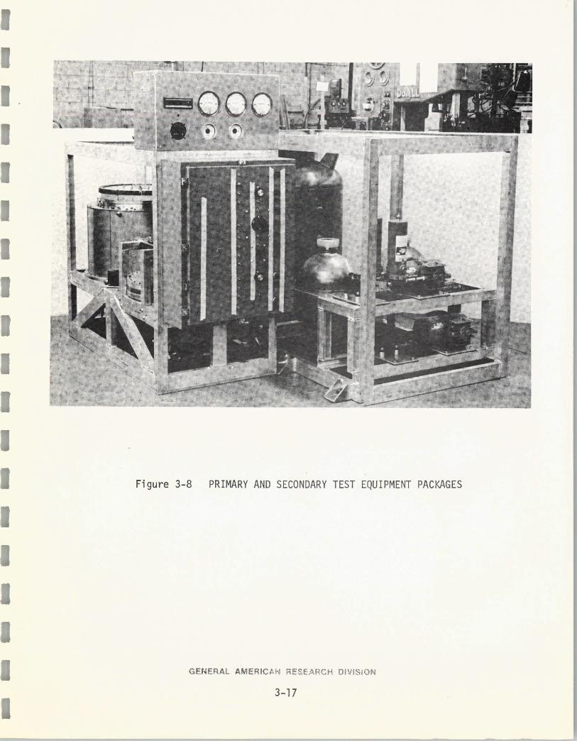
-Figure 3-8 PRIMARY AND SECONDARY TEST EQUIPMENT PACKAGES
-7"
I
GENERAL AMERICAN RESEARCH OIVISiON
3-17
IlI
I
I
IIIIII
I
3 Figure 3-9 PRIMARY TEST EQUIPMENT PACKAGE, LEFT SIDE IEW
I
GENEFRAL AMERICAN EAC OIVISlONa
3 3-18
III
II
1I ~
II Figure 3-10 PRIMARY TEST EQUIPMENT PACKAGE, RIGHT SIDE VIEW
1
III
13-19
GF NF A AMEICA, SE, ,H ~vI
9. Antifoam reservoir and metering valve
10. Condensate water pump (pumpout from condenser)
11. Condenser coolant loop
a. Liquid-to-liquid heat exchanger
b. Recirculation pump
c. Liquid expansion chamber
12. Electrical control box and panel
13. Instrumentation panel.
The evaporator, catalyst unit, vapor filter, and condenser (the components
which process the distillate vapor) are interconnected by stainless steel tubing,
preformed bends, and have 0-ring seals at flanged joints. Heat transfer liquid
loops (not yet assembled) will be constructed with small diameter tubing and
flareless swagelok sittings.
Components secured in the secondary frame are as follows:
1. Cooling unit (ice reservoir) and cold water loop
recirculating pump
2. Vacuum pumps and pre-dryer (desiccant bed)
3. Urine tank
4. Recovered water collection tank.
The secondary frame is on the right side in Figure 3-8. The urine tank
and the recovered water tank are the spherical-shaped components located near
midlength of the frame. Two diaphragm vacuum pump units, each with its own drive
motor are located in the near end of the frame. The cooling unit is the large
cylindrical tank (partially hidden) at the rear of the frame. It is a 50-gallon
steel tank with an 8-inch removable top cover for resupplying ice prior to each
test run.
An electrical controls enclosure containing switches, circuit breakers,
fuses, panel lights, transformers, variable resistors, terminal strips, power
GENERAL AMERICAN RESEARCH DIVISiON
3-20
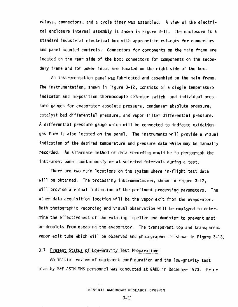
relays, connectors, and a cycle timer was assembled. A view of the electri-
cal enclosure internal assembly is shown in Figure 3-11. The enclosure is a
standard industrial electrical box with appropriate cut-outs for connectors
and panel mounted controls. Connectors for components on the main frame are
located on the rear side of the box; connectors for components on the secon-
dary frame and for power input are located on the right side of the box.
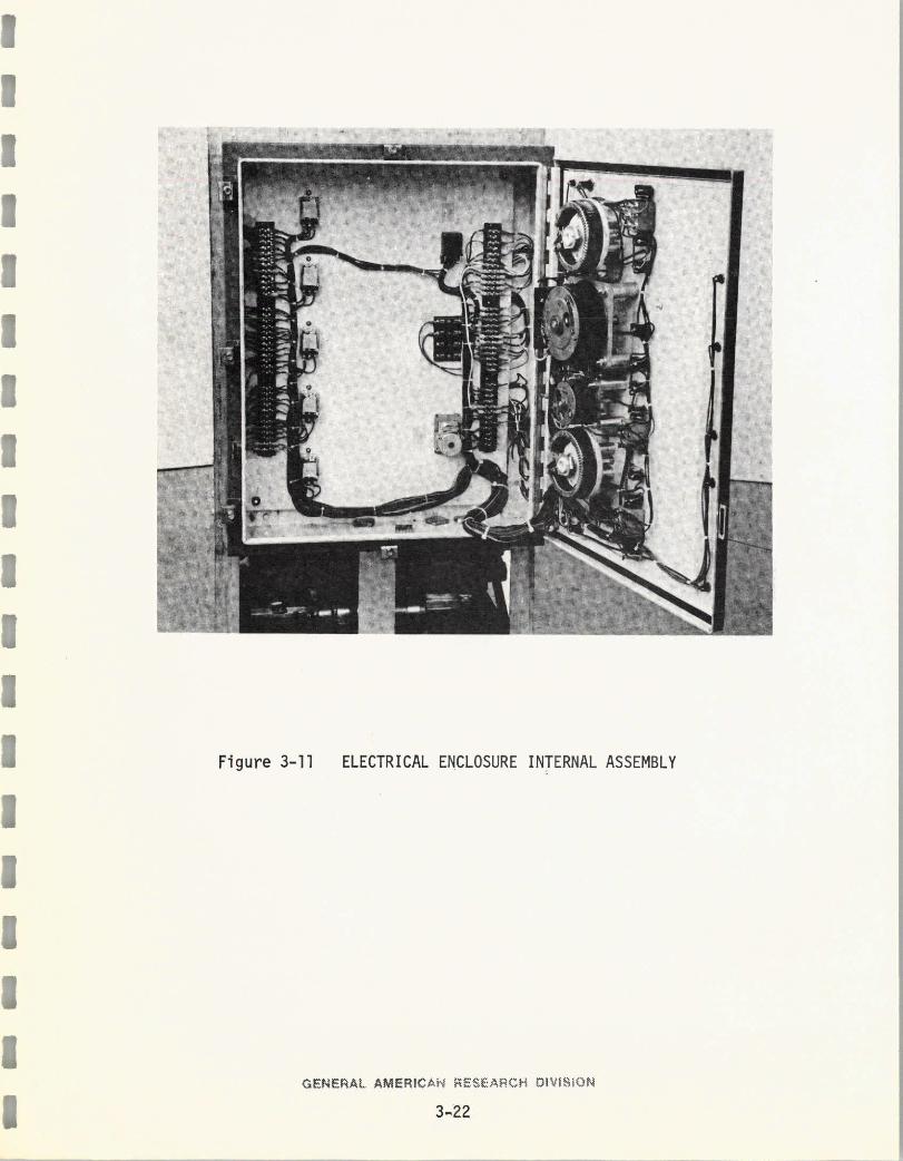
An instrumentation panel was fabricated and assembled on the main frame.
The instrumentation, shown in Figure 3-12, consists of a single temperature
indicator and 18-position thermocouple selector switch and individual pres-
sure gauges for evaporator absolute pressure, condenser absolute pressure,
catalyst bed differential pressure, and vapor filter differential pressure.
A differential pressure gauge which will be connected to indicate oxidation
gas flow is also located on the panel. The instruments will provide a visual
indication of the desired temperature and pressure data which may be manually
recorded. An alternate method of data recording would be to photograph the
instrument panel continuously or at selected intervals during a test.
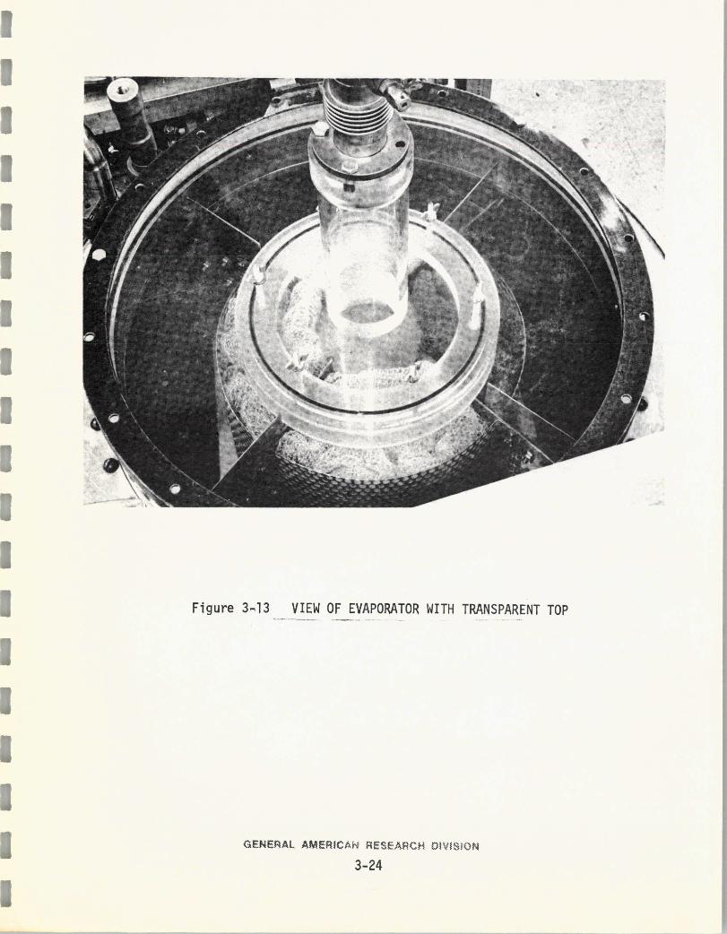
There are two main locations on the system where in-flight test data
will be obtained. The processing instrumentation, shown in Figure 3-12,
will provide a visual indication of the pertinent processing parameters. The
other data acquisition location will be the vapor exit from the evaporator.
Both photographic recording and visual observation will be employed to deter-
mine the effectiveness of the rotating impeller and demister to prevent mist
or droplets from escaping the evaporator. The transparent top and transparent
vapor exit tube which will be observed and photographed is shown in Figure 3-13.
3.7 Present Status of Low-Gravity Test Preparations
An initial review of equipment configuration and the low-gravity test
plan by S&E-ASTN-SMS personnel was conducted at GARD in December 1973. Prior
GENERAL AMERICAN RESEARCH DIVISiON
3-21
II
I
III ,
I
I
I
I
IFigure 3-11 ELECTRICAL ENCLOSURE INTERNAL ASSEMBLY
I
II
GENERAL AMER|CAN F;SE,,'.,M W|VI.iON53.22
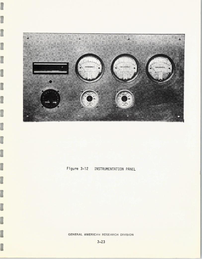
Figure 3-12 INSTRUMENTATION PANELI
I ENERAL AMERICAN RESEARCH DIVISION
3,23
I .
I '
3 Figure 3 13 VIEW OF EVAPORATOR WITH TRANSPARENT TOP
GENERAL AMERICAN RESE ARCH DIV[~SON
3-24
to delivery of the system to NASA/JSC for low-gravity testing, certain work
items remain to be completed. These tasks are in the areas of system assembly,
ground performance tests, final low-gravity test plan, and NASA and GARD co-
ordination.
3.7.1 System Assembly
Equipment as Assembled - The following assembly tasks are to be completed:
1. Labeling of control panel
2. Installation of thermocouple assemblies and extension leads
to temperature indicator
3. Installation of pressure sensing lines between component
and instrumentation panel.
4. Installation of tubing for the four liquid loops, namely
a. Glycol coolant
b. Ice water
c. Hot silicone oil
d. Warm water.
5. Installation of thermal insulation on catalyst unit, con-
denser, and ice reservoir.
Modifications to Equipment as Assembled - A review by S&E-ASTN-SMS of
the VD/VF equipment to be installed in the test aircraft indicated that the
following modifications are necessary:
1. Round-off of edges, corners, and protrusions
2. Installation of padding on outermost frame members for
test personnel safety
3. Extension of base plate on main frame so that floor tie-
down holes are outside of frame
4. Addition of camera and photolight mounts above evaporator
GENERAL AMERICAN RESEARCH DIVISiON
3-25
5. Provision of 20-foot power cable with fuse box
6. Provision of a separate 20-foot cord from cameras
and photolights.
3.7.2 Ground Performance Tests
The VD/VF system is to be tested in the laboratory in the configuration
which will be low-gravity tested. This check out testing will include all
system components and support components as they will be used in low-gravity
tests. Prior to low-gravity testing, the system will also be subjected to
continuous testing of three days duration. The check-out testing will be con-
cerned with determining suitable lighting and camera operation and with test
operator familiarization with camera operation and data recording. A three-
day duration test is to be conducted to obtain performance data for ground
tests; this test data may subsequently be compared to low-gravity test data.
With the exception of water quality analyses, the same instrumentation
and procedures as for low-gravity tests are to be employed to obtain the fol-
lowing measurements and analyses:
1. Duration of test run
2. Volume per test run of:
a. Urine feed
b. Water recovered
3. Flow rate of oxidation gas to catalyst bed
4. Temperature of:
a. Heating liquid entering evaporator heating jacket
b. Heating liquid exiting evaporator heating jacket
c. Urine liquid supplied from storage
d. Urine liquid inside evaporator
e. Vapor exiting evaporator
GENERAL AMERICAN RESEARCH DIVISiON
3-26
f. Heating liquid entering catalytic oxidation unit
g. Heating liquid exiting catalytic oxidation unit
h. Vapor entering preheater
i. Vapor exiting preheater (entering catalyst bed)
j. Vapor exiting catalyst bed (entering vapor filter)
k. Vapor entering recuperator
1. Coolant entering condenser
m. Coolant exiting condenser
n. Vapor entering condenser
o. Condensate within condenser
p. Condensate pumped to storage
q. Ambient air temperature
5. Absolute pressure of:
a. Vapor exiting evaporator
b. Noncondensable gases exiting condenser
6. Differential pressure of:
a. Vapor entering and exiting catalytic oxidation unit
b. Vapor entering and exiting vapor filter
7. Twice daily samples of potable water pumped out of condenser
to determine levels of:
a. Total carbon
b. Total organic carbon
c. pH
d. Ammonia
e. Conductivity
f. Turbidity
g. Viable bacteria density (MPN)
GENERAL AMERICAhN RESEARCH DIVISiON
3-27
3.7.3 Low-Gravity Test Plan
A test plan has been prepared in preliminary form and reviewed by S&E-
ASTN-SMS. The test procedures need to be expanded to describe the variables
to be controlled by the test operator(s). Detail procedures will be deter-
mined during ground check-out testing; these will be listed in the final test
plan.
3.7.4 NASA/MSFC and GARD Preparations Coordination
GARD personnel who will be assisting in the low-gravity tests have com-
pleted the following preflight requirements:
1. Security clearance
2. FAA Class II physical
3. Physiological training.
Resulting from the NASA/MSFC and GARD coordination meeting in December
1973, the following known areas of coordination have been identified:
1. MSFC recommends that GARD try out the cameras and lighting
during ground testing; NASA/MSFC will request a loan of a
normal speed camera (24 frames per second) and a high-speed
camera (64/120 frames per second) to GARD for use in fabri-
cating camera mounts and trying out the lighting during ground
testing.
2. A hand-held camera may be used to photograph the transparent
outlet tube at the evaporator. If used, the hand-held camera
will be operated by a NASA photographer.
3. GARD will include the weights of each test rig along with
the installation instructions.
GENERAL AMERICAN RESEARCH DOVISiON
3-28