Embed Size (px)
Citation preview
" ~LEV,(
NOTHOHIO RIVER BASIN
NORTH BRANCH BLACKLICK CREEK, CAMBRIA COUNTY
SPENNSYLVANIA
NDI I.D. PA- 0437DER I.D. 11-20
OWNER: CAMBRIA TWP. WATER AUTHORITY
PHASE I INSPECTION REPORTNATIONAL DAM INSPECTION PROGRAM
II
1 9
t7 •"c.C4.)
PRI'PARI'D FOR
SDEPARTMENT OF THL ARMY. -,
LA. BALTIMORE DISTRICT, CORPS OF ENGINEERS " .
f BALTIMORE, MARYLAND 21203
BY
D'APPOLONIA CONSULTING ENGINEERS
10 DUFF ROADPITTSBURGH. PA. 1S235
A UG~UST 1981
App(ov, for publ• i .=Gt81 12 28 179,
PREFACE
This report is prepared under guidance contained in the RecommendedGuidelines for Safety Inspection of Dams, for Phase I Investigations.Copies of these guidelines may be obtained from the Department ofthe Army, Office of Chief of Engineers, Washington, D.C. 20314.
The purpose of a Phase I investigation is to identify expeditiouslythose dams which may pose hazards to human life or propercy. Theassessment of the general condition of the dam is based upon visualobservations and review of available data. Detailed investigationsand analyses involving topographic mapping, subsurface investigations,material testing, and detailed computational evaluations are beyond thescope of a Phase I investigation; however, the inspection is intended toidentify any need for such studies which should be performed by the *,owner.
In reviewing this report, it should be realized that the reporteCcondition of the dam is based on observations of field conditions atthe time of inspection along with data available to the inspectionteam. In cases where the reservoir was lowered or drained prior to .inspection, such action, while improving the stability of the dam,
removes the normal load on the structure and may obscure certainconditions which might otherwise be detectable if inspected underthe normal operating environment of the structure.
It is important to note that the condition of the dam depends on numerous Iand constantly changing internal and external factors which are evolu-tionary in nature. It would be incorrect to assume that the presentcondition of the dam will continue to represent the condition of the damat some point in the future. Only through frequent inspections canunsafe conditions be detected and only through continued care andmaintenance can these conditions be prevented or corrected.
Phase I inspections are not intended to provide detailed hydrologicand hydraulic analyses. In accordance with the established Guidelines,the spillway design flood is based on the estimated "Probable MaximumFlood" for the region (greatest reasonably possible storm runoff), orfractions thereof. The spillway design flood provides a measure ofrelative spillway capacity and serves as an aid in determining the needfor more detailed hydrologic and hydraulic studies, considering the sizeof the dam, its general condition and the downstream damage potential.
The assessment of the conditions and recotm'.ndations was made by thecorsulting engineer in accordance with generally and currently acceptedengineering principles and practices.
"4N ) j '
PHASE I REPORTNATIONAL DAM INSPECTION PROGRAM
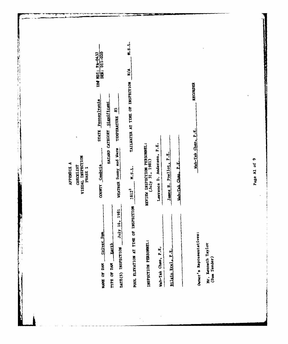
NAME OF DAM: Colver DamSTATE LOCATED: PennsylvaniaCOUNTY LOCATED: CambriaSTREAM: North Branch of Blacklick Creek, a secondary tributary of the
Conemaugh RiverSIZE CLASSIFICATION: SmallHAZARD CLASSIFICATION: SignificantOWNER: Cambria Township Water AuthorityDATE OF INSPECTION: July 16, 1981 and July 31, 1981
ASSESSMENT: Based on the evaluation of the existing conditions, thestructural condition of Colver Dam is considered to be good.
S 9 The dam is classified as a small dam in the significant hazard category,According to the recommended criteria, small dams in the significanthazard category are required to pass a flood whose magnitude rangesbetween the 100-year flood and 50 percent of the Probable Maximum Flood(PMF).'.In view of the size of the dam which is closer to the lower limitof the Small size classification, the 100-year flood was selected as thespillway design flood. The 100-year flood peak was determined accordingto the recommended procedure and was found to be in excess -if the spillwaycapacity. Therefore, the capacity of the spillway is classified as
inadequate.
--The following recommendations shoukd be implemented immediately or on acontinuing basis:
(1> The owner should determine the nature and extentof modifications needed and implement thesemeasures to provide adequate spillway capacity.
I
2• Around-the-clock surveillance should be providedduring unusually heavy rainfall and/or runoff.In addition, a formal warning system should bedeveloped to alert downstream residents in theevent of an emergency.
/
!31 The owner should develop and follow a formaloperating and maintenance plan ar~d should inspectthe dam regularly._
ii
' , ,, , , i In

Vj Assessment - Colver Dam
C) PREGISSODNAL
Lawrence D. Atdersen
1,ENGINEERLawrence D. Andersen, P.E.
SYVice President
August 26, 1981Date
Approved by:
Sf J~J ES W.- PECK . .I onel, Corps of Engineers
strict Engineer
Date I
iii
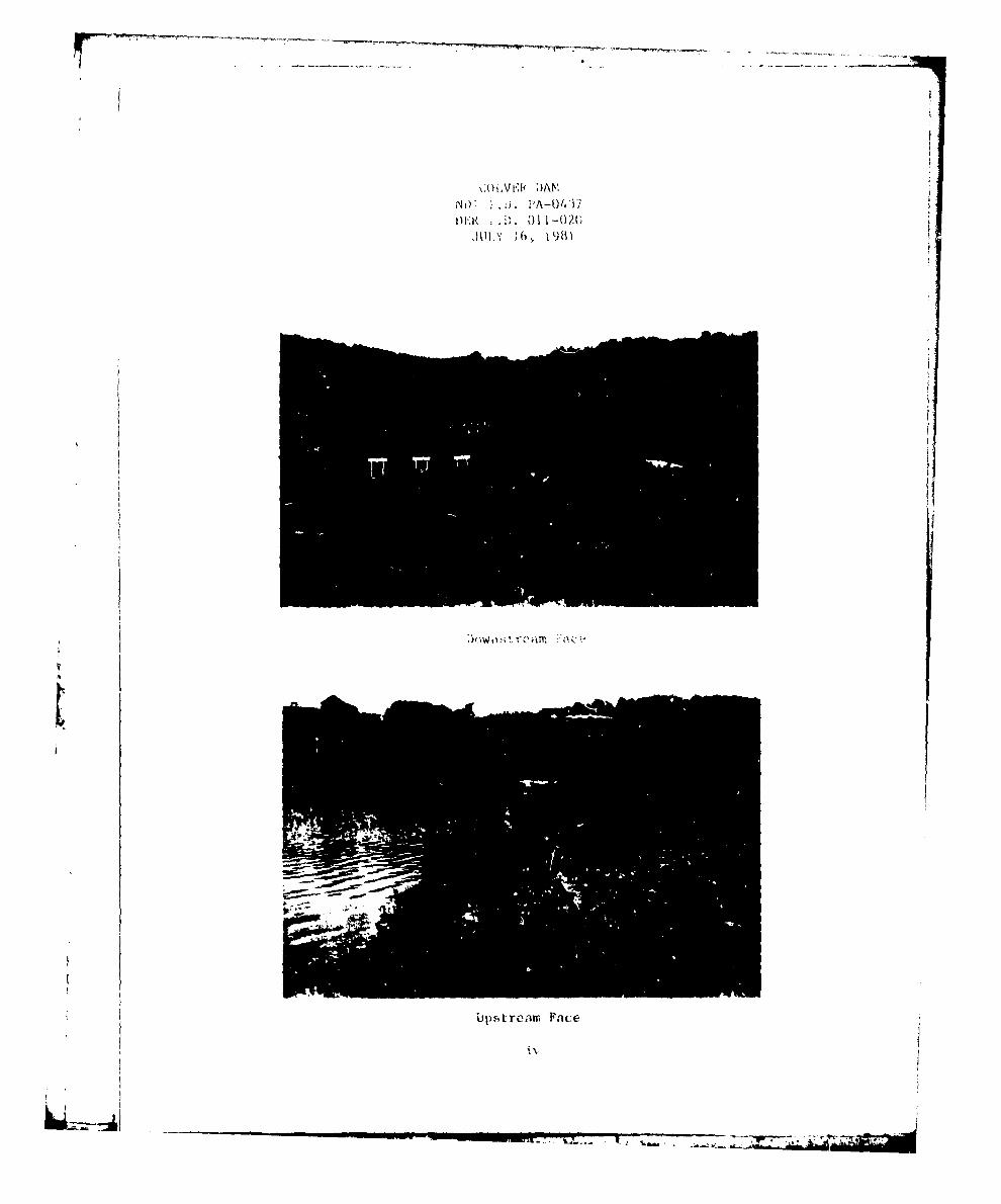
\;Oi,Vr'b[ ;)ANNOpjj ,. PA-O) 37
Up1 se1, m F ai
I Ubpstreanr Face
1\,
-T2_________________
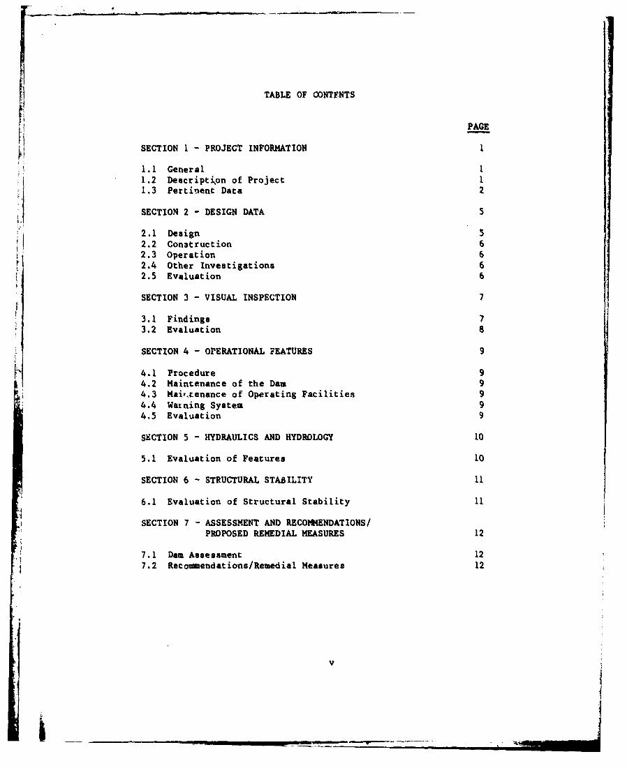
TABLE OF CONTFNTS
PAGE
SECTION 1- PROJECT INFORMATION I
1.1 General 11.2 Description of Project 11.3 Pertinent Data 2
SECTION 2 - DESIGN DATA
2.1 Design 62.2 Construction 62.3 Operation 62.4 Other Investigations 62.5 Evaluation 6
SECTION 3 - VISUAL INSPECTION 7
3.1 Findings 73.2 Evaluation 8
SECTION 4 - OPERATIONAL FEATURES 9
4.1 Procedure 94.2 Maintenance of the Dam 94.3 Maiv•cenance of Operating Facilities 94.4 Waining System 94.5 Evaluation 9
SECTION 5 - HYDRAULICS AND HYDROLOGY 10
5.1 Evaluation of Features 10
SECTION 6 - STRUCTURAL STABILITY 11
6.1 Evaluation of Structural Stability 11
SECTION 7 - ASSESSMENT AND RECOMMENDATIONS/PROPOSED REMEDIAL MEASURES 12
7.1 Dam Assessment 127.2 Recoumendations/Remedial Measures 12
v
iI __ ___

TABLE OF CONTENTS(Continued)
APPENDIX A - CHECKLIST, VISUAL INSPECTION, PHASE I
APPENDIX B - CHECKLIST, ENGINEERING DATA, DESIGN, CONSTRUCTION,OPERATION, AND HYDROLOGIC/HYDRAULIC, PHASE I
APPENDIX C - PHOTOGRAPHSAPPENDIX D - HYDROLOGY AND HYDRAULICS ANALYEES
APPENDIX E - PLATESAPPENDIX F - REGIONAL GEOLOGY
*1
vi

PHASE I REPORTNATIONAL DAM INSPECTION PROGRAM
COLVER DAMNDI I.D. PA-0437DER I.D. 011-020
SECTION 1PROJECT INFORMATION
1.1 General
a. Authority. The inspection was performed pursuant to theauthority granted by The National Cam Inspection Act, Public Law 92-367,to the Secretary of the Army, through the Corps of Engineers, to conductinspections of dams throughout the United States.
b. Purpose. The purpose of this inspection is to determine if thedam constitutes a hazard to human life or property.
1.2 Description of Project
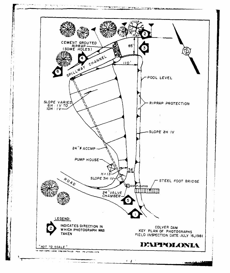
a. Dam and Appurtenances. The Colver Dam, also known as VeteraDam, consists of an earth embankment approximately 490 feet long with amaximum height of 13 feet from the downstream toe. The embankment crestwidth varies between about 38 feet near the left abutment (lookingdownstream) and about 110 feet near the right abutment. The downstreamembankment slope for a distance of approximately 150 feet near the leftabutment is approximately 3 horizontal to 1 vertical. The slope isflatter along the remaining embankment portions, in the range of 6horizontal to 1 vertical. The downstream face of the dam is covered withgrass. The upstream embankment slope above normal pool level is approxi-mately 2 horizontal to 1 vertical and is partially covered with riprap.
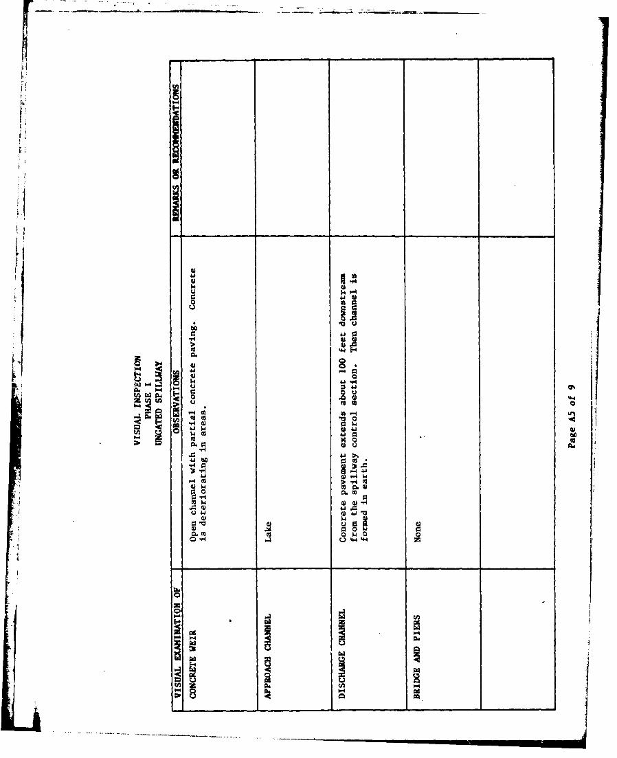
The spillway of the dam consists of an 85-foot-wide open channel locatedat the right abutment. A three-foot-high masonry wall is located on theembankment side of the spillway. The spillway discharge channel ispartially paved with concrete. The concrete slab terminates approxi-mately 100 feet downstream from the control section of the spillway.The downstream end of the paved discharge channel is protected withgrouted riprap.
The low level outlet of the dam consists of a 24-inch-diameter cast ironpipe located through the dam near the left abutment. Flow-through thispipe is controlled by a valve which is located along the center line ofthe embankment crest alignment. Flow through the cast iron pipe dis-charges into a 24-inch-diameter corrugated metal pipe which apparentlyruns from the left to the right abutment and discharges into the unpavedportion of the spillway discharge channel. This outlet constitutesthe emergency drawdown facility of the dam.
b1
"-__ _ _ _ _ _
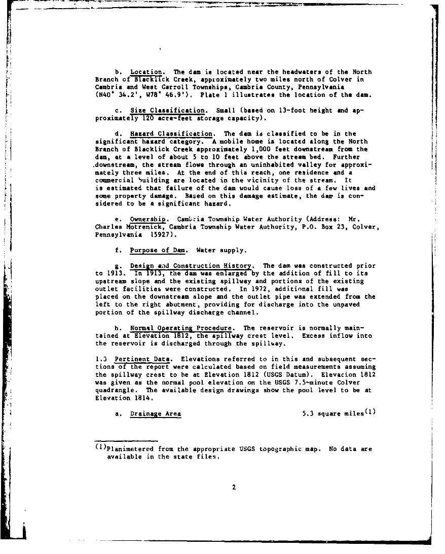
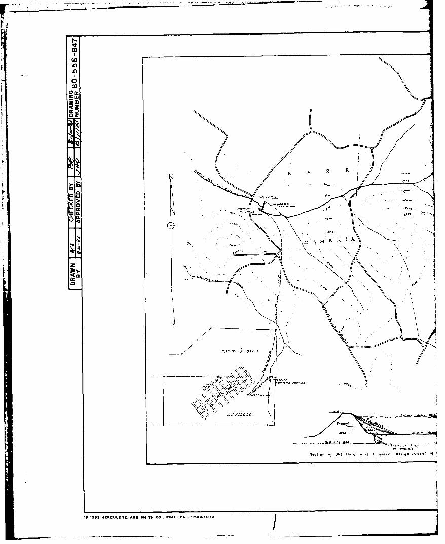
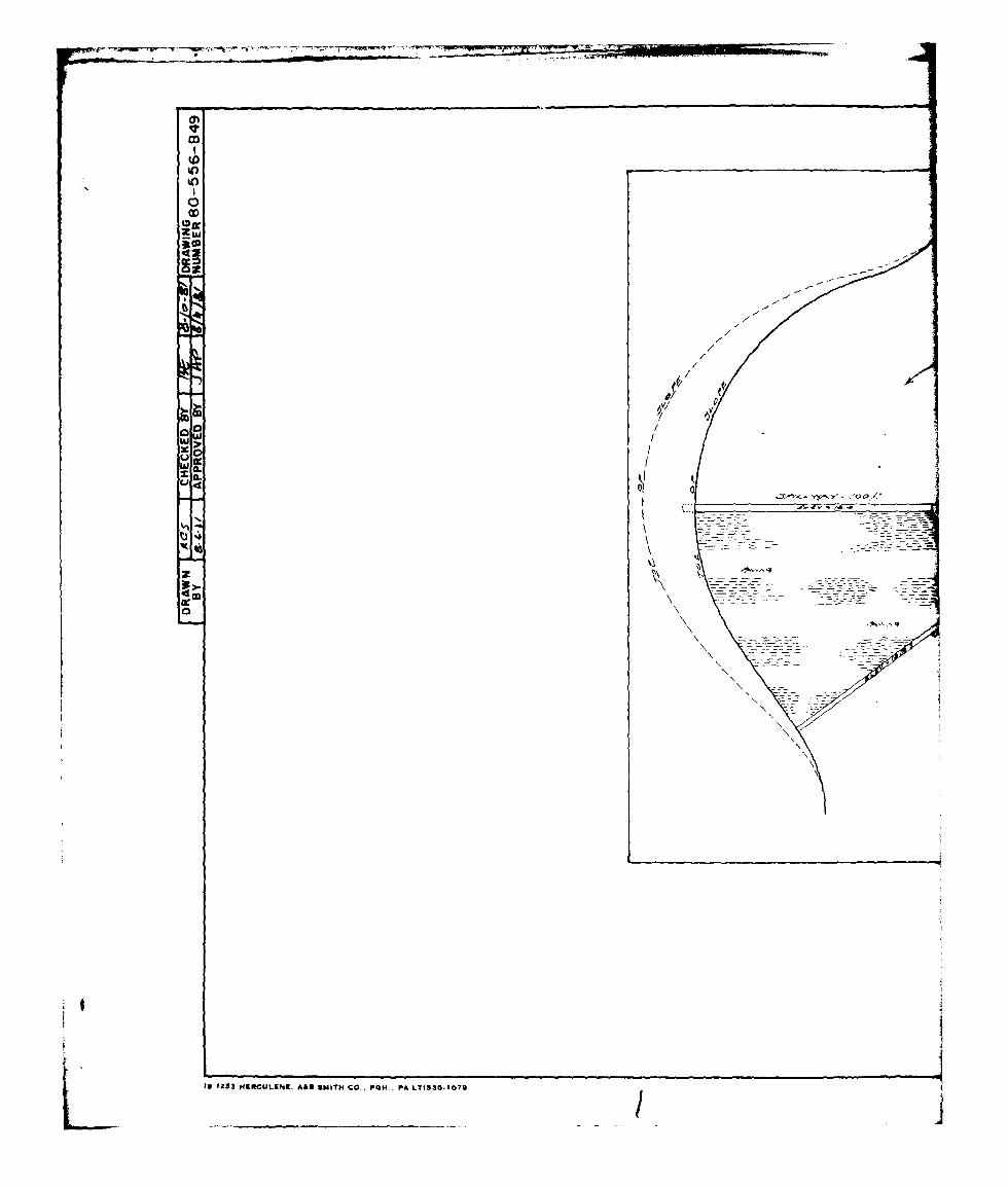
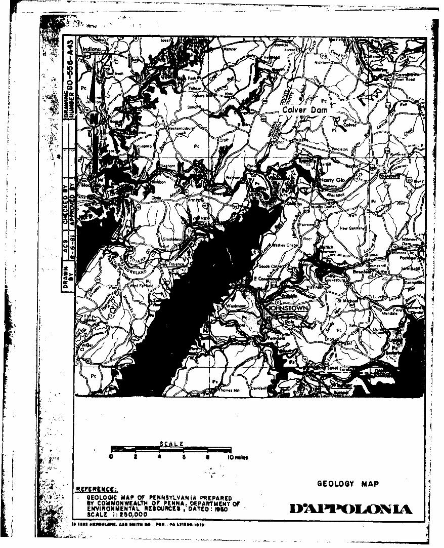
b. Location. The dam is located near the headwaters of the NorthBranch of Blacklick Creek, approximately two miles north of Colver inCambria and West Carroll Townships, Cambria County, Pennsylvania(N40" 34.2', W78T 46.9'). Plate 1 illustrates the location of the dam.
c. Size Classification. Small (based on 13-foot height and ap-proximately 120 acre-feet storage capacity).
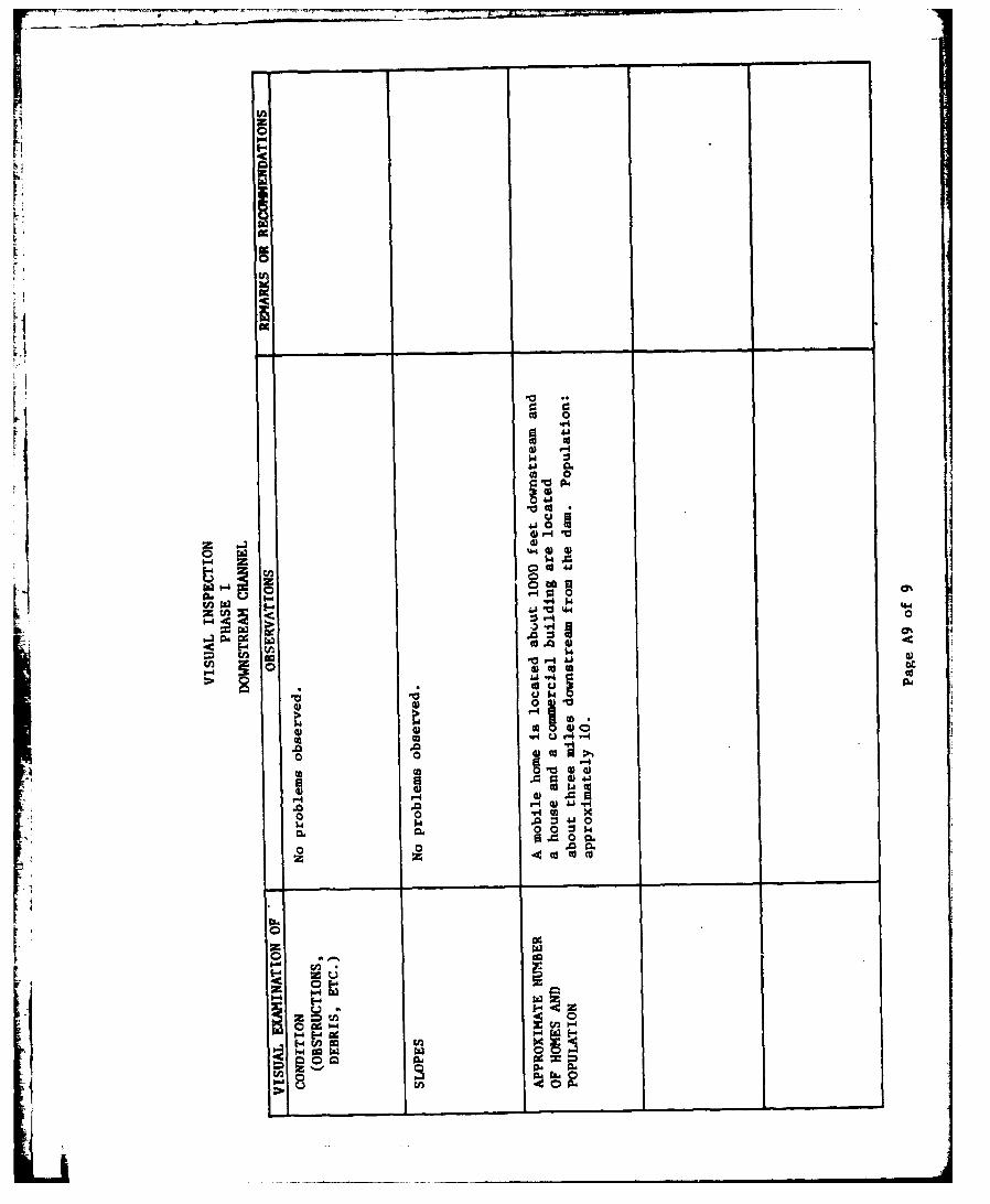
d. Hazard Classification. The dam ia classified to be in thesignificant hazard category. A mobile home is located along the NorthBranch of Blacklick Creek approximately 1,000 feet downstream from thedam, at a level of about 5 to 10 feet above the stream bed. Furtherdownstream, the stream flows through an uninhabited valley for approxi-mately three miles. At the end of this reach, one residence and acomnercial Suilding are located in the vicinity of the stream. Itis estimated that failure of the dam would cause loss of a few lives andsome property damage. Based on this damage estimate, the dam is con-sidered to be a significant hazard.
e. Ownership. CamLcia Township Water Authority (Address: Mr.Charles Motrenick, Cambria Township Water Authority, P.O. Box 23, Colver,Pennsylvania 15927).
f. Purpose of Dam. Water supply.
g. Design and Construction History. The dam was constructed priorto 1913. In 1913, the dam was enlarged by the addition of fill to itsupstream slope and the existing spillway and portions of the existingoutlet facilities were constructed. In 1972, additional fill wasplaced on the downstream slope and the outlet pipe was extended from theleft to the right abutment, providing for discharge into the unpavedportion of the spillway discharge channel.
h. Normal Operating Procedure. The reservoir is normally main-tained at Elevation 1812, the spillway crest level. Excess inflow intothe reservoir is discharged through the spillhay.
1.3 Pertinent Data. Elevations referred to in this and subsequent sec-tions of the report were calculated based on field measurements assumingthe spillway crest to be at Elevation 1812 (USGS Datum). Elevacion 1812was given as the normal pool elevation on the USGS 7.5-minute Colverquadrangle. The available design drawings show the pool level to be atElevation 1814.
a. Drainage Area 5.3 square miles(l)
(1)Planimetered from the appropriate USGS topographic map. No data areavailable in the state file•i.
2
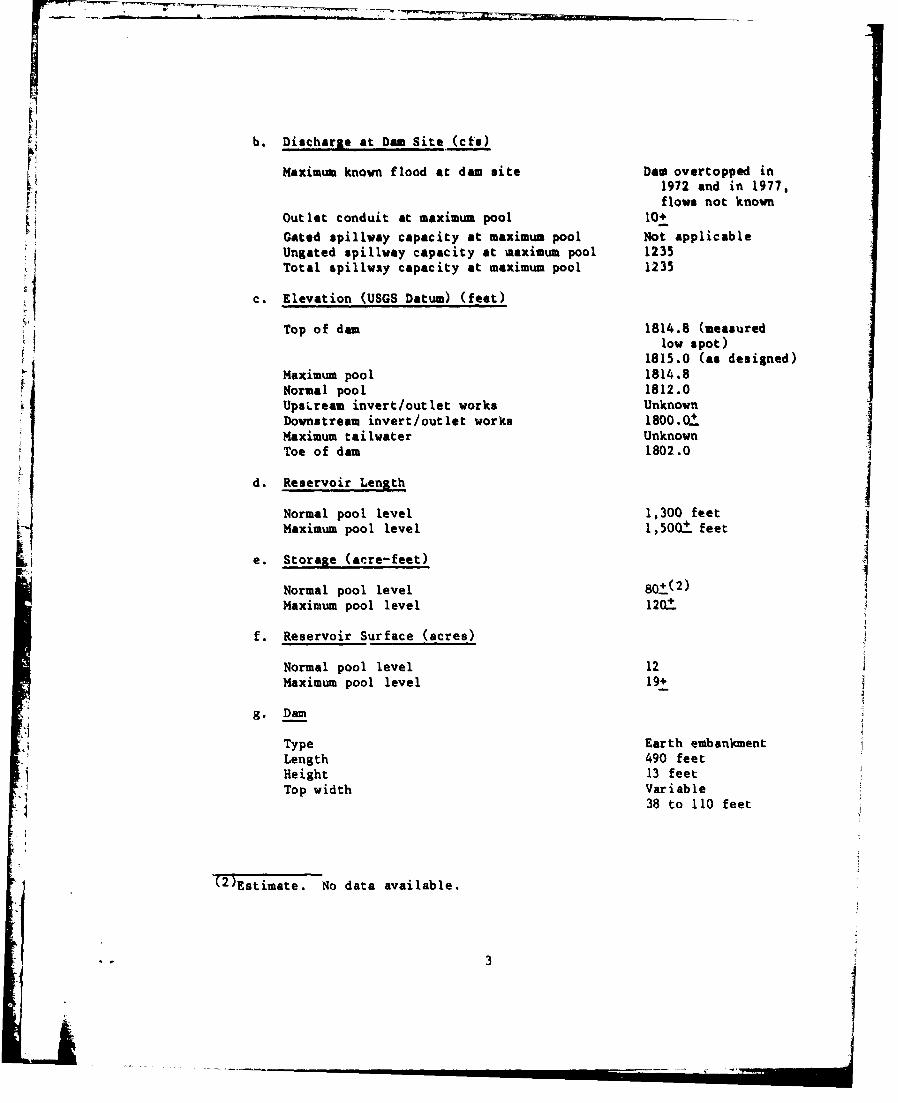
b. Discharge at Dam Site (cts)
Maximum known flood at dam site Dam overtopped in•i 1972 and in 1977,
flows not knownOutlet conduit at maximum pool 10+
Gated spillway capacity at maximum pool Not applicableUngated spillway capacity at maximum pool 1235Total spillway capacity at maximum pool 1235
c. Elevation (USGS Datum) (feet)
Top of dam 1814.8 (measuredlow spot)
1815.0 (as designed)Maximum pool 1814.8Normal pool 1812.0UpsLream invert/outlet works UnknownDownstream invert/outlet works 1800.0±.Maximum tailwater UnknownToe of dam 1802.0
d. Reservoir Length
Normal pool level 1,300 feetMaximum pool level 1,500±. feet
e. Storage (acre-feet)
Normal pool level 80+.(2)Maximum pool level 1201
f. Reservoir Surface (acres)
Normal pool level 12Maximum pool level 19+
g. Dam
Type Earth embankmentLength 490 feetHeight 13 feetTop width Variable
38 to 110 feet
(2)Estimate. No data available.
* * 3

Side slopes Downstream: Varies,3li-6H: IV
Upstream: 2H:IVZoning NoImpervious core NoCutoff YesGrout curtain No
h. Regulatinu Outlet
Type 24-inch-diame,:er cautiron pipe
Length 50 0. feetAccess Valve located on dim
crest near left abutmentClosure Manually operated valve
i. Spil1lway
Type Partially concrete pavedopen channel
Length 85 feet (perpendicularto flow)
Crest elevation 1812.0Upstream channel LakeDownstream channel Earth channel
i4
V SECTION 2DESIGN DATA
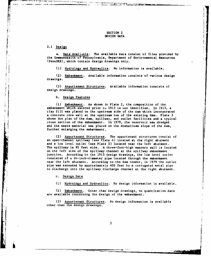
2.1 Design
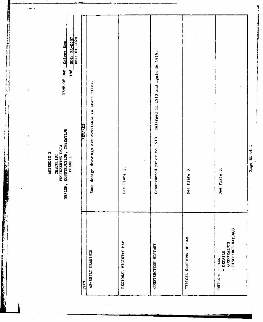
a. Data Available. The available data consist of files provided bythe Commnonwealth or Pennsylvania, Department of Environmental Resources(PennDER), which contain design drawings only.
24 (1) Hydrology and Hydraulics. No information is available.
(2) Embankment. Available information consists of various designdrawings.
(3) Aopurtenant Structures. Available information consists of
design drawings.
b. Design Features
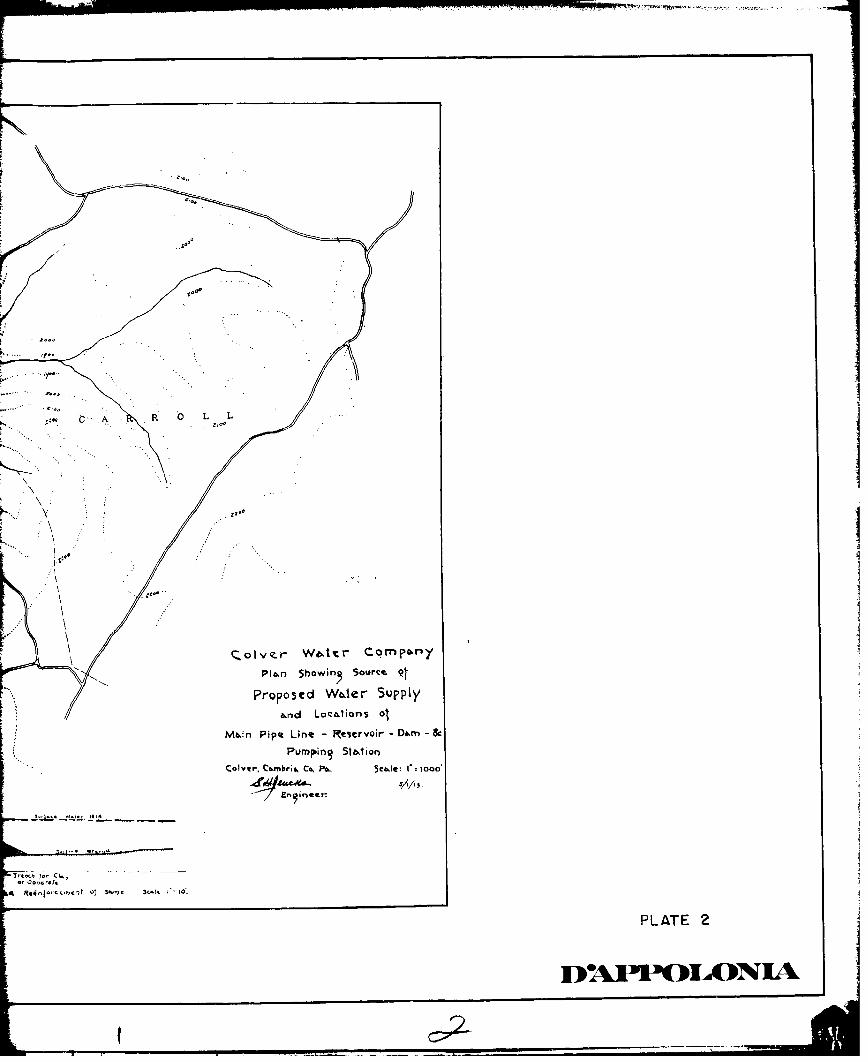
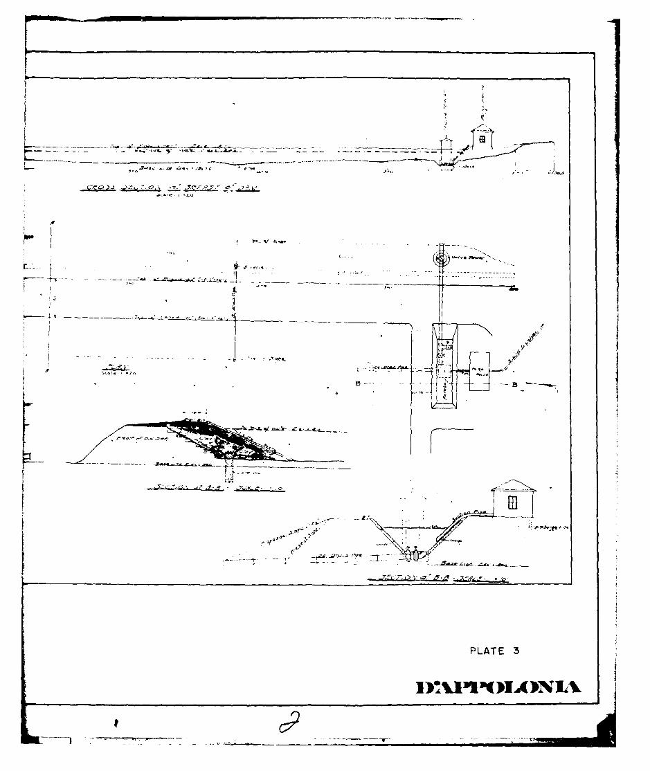
(1) Embankment. As shown in Plate 2, the composition of theembankment which exi.sted prior tu 1913 is uot identified. in 1913, aclay fill was placed on the upstream side of the dam which incorporateda concrete core wall at the upstream toe of the existing dam. Plate 3shows the plan of the dam, spillway, and outlet facilities and a typicalcross section of the embankment. In 1979, the reservoir was dredgedand the waste material was placed on the downstream slope of the dam,further enlarging the embanikment.
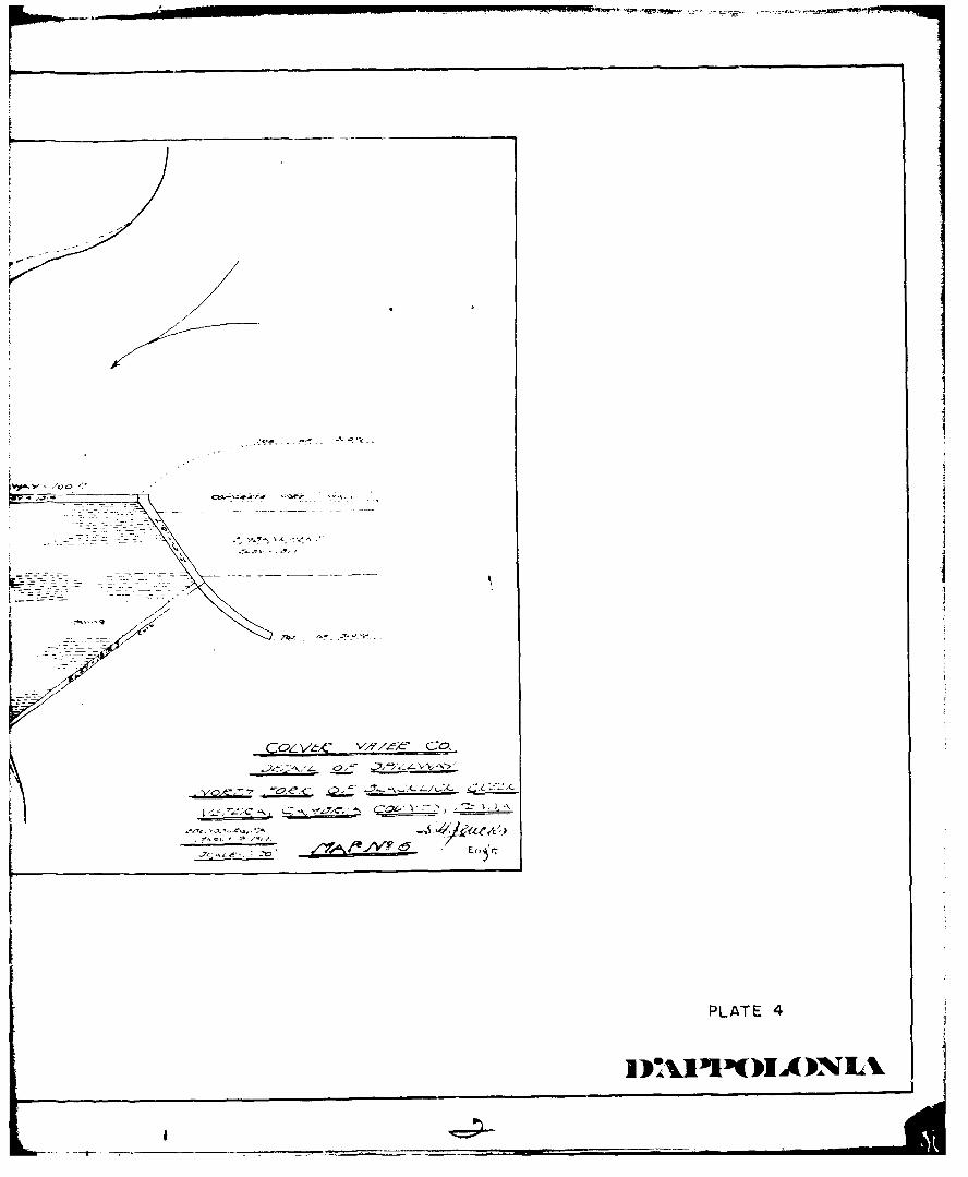
(2) Appurtenant Structures. The appurtenant structures consist ofan open-channel spillway (Wee-Plate 4) located at the right abutmentand a low level outlet (see Plate 3) located near the left abutment.The spillway is 85 feet wide. A three-foot-high masonry wall is locatedon the left side of the spillway channel at the spillway embankmentjunction. According to the 1913 design drawings, the low level outletconsisted of a 24-inch-diameter pipe located through the embankmentnear the left abutment. According to the dam tender, in 1979 the outletpipe was extended by approximately 400 feet by a corrugated metal pipeto discharge into the spillway discharge channel at the right abutment.
c. Design Data
(1) Hydrology and Hydraulics. No design information is available.
4 (2) Embankment. Other than design drawings, no quantitative dataare available concerning the design of the embankment.
(3) Appurtenant Structures. No design information is availableother than the design drawings.
5
2.2 Construction. No information is available concerning the construc-tion of the dam. As previously noted, the dam was originally built
prior to 1913 and was modified in 1913 and again in 1979.
2.3 Operation. There are no formal operating records maintained for
the dam. According to the dam tender, the dam may have overtopped in1972 and in 1977.
2.4 other Investigations. None reported.
2.5 Evaluation
-a. Availability. The available information is limited. However,it is considered to be sufficient for Phase I Inspection purposes.
b. Adequacy.
(1) Hydrology and Hydraulics. No information is available toassess the adequacy of the spillway.
(2) Embankment. Other than design drawings, no other design in-formation is available to determine the adequacy of the design.
(3) Appurtenant Structures. No quantitative data are available toassess the adequacy of appurtenant structures.
6j
SECTION3
VISUAL INSPECTION
3.1 Findings
a. General. The onaite inspection of the Colver Dam consisted of:
1. The visual inspection of the embankment, abutments,and embankment toe.
2. The visual examination of the spillway and reservoirportions of the outlet works.
3. The evaluation of the downstream area hazard potential.
The specific observations are illustrated on Plate 5.
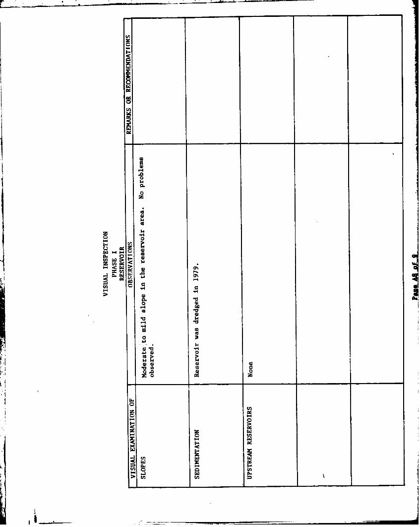
b. Embankment. In general, the inspection of the embankment con-sisted of searching' for indications of structural distress, such ascracks, subsidence, bulging, wet areas, seeps and boils, and observinggeneral maintenance conditions, vegetative cover, erosion, and othersurficial features.
In general, the condition of the dam is considered to be good. No signsof di~stress or seepage were noted. The downstream embankment slope andcrest are covered with grass and were found to be adequately maintained.
The dam crest was surveyed relative to the spillway crest elevation andthe lowest area was fcund to be within 0.2 foot of the design crestlevel. The dam crest profile, according to the field measurements, isillustrated in Plate 6.
c. Appurtenant Structures. The appurtenant structures were exam-L-ied for deterioration or other- signs of distress and for obstructionsthat could limit flow. The spillway structure was found to be in faircondition. The spillway slab was found to have cracked and deterioratedin some areas. Some maintenance may be required to prevent furtherdeterioration. Only the downstream end of the outlet pipe was visible.The outlet pipe valve was operated by the dam tender and was observedto be functional.
d. Reservoir Area. A map review indicates that the watershed is4 predominantly covered by farmlands and woodlands. No signs of any landslide
activity were found in the vicinity of the reservoir. Review of theregional geology is included in Appendix F.
e. Downstream Channel. The downstream channel was found to be4 stable within the vicinity of the dam. A further description of the
downstream conditions is included in Paragraph 1.2 d.
7

3.2 Evalual•ion. The Colver Dan was found to be in good condition and
adequately maintained. No conditions were observed that would require
remedial action at this time. The owner should consider repairing the
spillway concrete to avoid further deterioration.
L8
:1
tII
H2¶ i II
8
SECTION 4
OPERATIONAL FEATURES
4.1 Procedure. There are no formal operating procedures for th,- dam,
The resroiris normally maintained at the spillway crest level withU excess inflow discharged through the spillway channel.
4.2 Maintenance of the Dam. The maintenance of the dam in consideredto be good. The crest and slopes of the dam are covered with grass andare adequately maintained.
4.3 Maintenance of Operatin; Facilities. The only operable facility ofthe damn is the low-level out let pipe valve. The valve was operated bythe dam tender, and was observed to be functional.
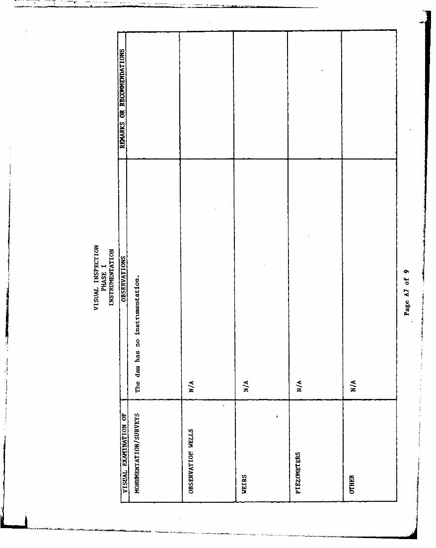
4.4 Warning System. No formal earning system exists for the dam.Telephone communication facilities are available via residences in thevicinity of the dam.
4.5 Evaluation. The maintenance condition of the dam is considered tobe good. Development of a formal warning system to alert downstreamresidents in the event of an emergency is recommended.
9

U
LSECTION 5
HYDRAULICS AND HYDROLOGY
5.1 Evaluation of Features
a. Design Data. The Colver Dam drains a watershed area of5.3 square miles and impounds a reservoir with a surface area of11.9 acrcs at normal pool level. The spillway structare consists of an85-foot-wide open channel located at the right abutment. The capacity ofthe spillway, based on the available freeboard relative to the low spoton the crest of the dam, is estimated to be t235 cfs.
b. Experience Data. As previously stated, Colver Dam is classifiedas a small dam in the significant hazard category. Under the recommendedcriteria for evaluating spillway discharge capacities, such impoundmentsare required to pass from the 100-year flood to one-half ProbableMaximum Flood (PHIF). In view of the low downstream damage potential,the 100-year flood was selected as the spillway design flood.
The peak flow of the 100-year flood was calculated according to therecommended procedure und was found to be 2200 cfs. The 100-year floodcalculations are included in Appendix D.
c. Visual Observations. On the date of inspection, no conditionswere observed that would Indicate ihat the spillway capacity would besignificantly reduced during the passage of a large flood.
[ d. Overtopping Potential. The available spillway capacity of j1227 cfs is less than the 100-year-flood peak of 2200 cfs. Therefore,the dam will be overtopped during floods with peak flows in excess ofthe spillway capasity.
e. Spillway Adequacy. The spillway capacity is less than therecoamended spillway design capacity of the 100-year flood. Therefore,the spillway is classified to be inadequate.
10
I. ... l l
SECTION 6STRUCTURAL STAB ILITY
6.1 Evaluation of Structural Stability
a. Visual Observations
(1) Embankment. As discussed in Section 3, the field observationsdid not reveal any signs of distress that would significantly affect theperformance of the structure at this time. In addition, no unsatisfactoryconditions have been reported in the past.
F "(2) Appurtenant Structures. No conditions were observed that wouldaffect the structural performance of the appurtenant structures.
b. Design and Construction Data.
(1) Embankment. The available design and construction informationdoes not provide quantitative data which might aid in the assessment ofthe embankment stability. However, as previously noted, the fieldobservations did not reveal any signs of distress which would signifi-cantly affect the stability of the dam at this time, and none werereported in the past. Therefore, based on vixual observations, thestructural stability of the dam is considered to be adequate.
(2) Appurtenant Structures. The review of available informationindicates that there are no apparent structural deficiencies that wouldsignificantly affect the performance of the appurtenant structures.
c. Operating Records. Not maintained.
d. Postconstruction Changes. The embankment was enlarged in 1913and again in 1979. Further description of the postconstruction modifica-tions are included in Section 2.1 b (1).
e. Seismic Stability. The dam is located in Seismic Zone 1. Basedon visual observations, the static stability of the dam is considezed tobe adequate. Therefore, based on the recommended criteria for the eval-uation of the sei:jmic stability of dams, the structure is presumed topresent no hazard as a result of earthquakes.
!1

SECTION 7ASSESSMENT AND RECOMMENDATIONS/PROPOSED REMEDIAL MEASURES
7.1 Dam Assessment
a. Assessment. The visual observations indicate that the condi-tion of Colver Dam is good. At this time, no conditions were observedthat would significantly affect the structural performance of the dam.
The dam is classified as a small dam in the significant hazard category.According to the recommended criteria, small dams in the significanthazard category are required to pass a flood whose magnitude rangesbetween the 100-year flood to 50 percent of the PMF. In view of the siteof the dam, which is closer to the lower limit of the small size classi-fication, the 100-year flood was selected as the spillway design flood.The spillway capacity was evaluated according to the recommended pro-cedure and was found to be less than the peak value of the 100-year floodwhich was selected as the spillway design flood relative to the size andhazard classification of the dam. Therefore, the spillway is consideredto be inadequate.
b. Adequacy of Information. The available information, in conjunc-tion with the visual observations, is considered to be sufficient fora Phase I evaluation.
c. Urgency. The following recommendations should be implementedimmediately or on a continuing basis.
d. Necessity for Additional Investigations. No additional inves-tigations are considered to be required at this time.
7.2 Recommendations/Remedial Measures. It is recoumended that:
1. The owner should determine the nature and extentof modifications needed and implement thesemeasures to provide adequate spillway capacity.
2. Around-the-clock surveillance should be providedduring unusually heavy rainfall and/or runoff.In addition, a formal warning system should bedeveloped to alert downstream residents in theevent of an emergency.
3. The owner should develop and follow a formaloperating and maintenance plan and should inspectthe dam regularly.
12
N
[.1
APPE•?DIX A
CHECKLISTVISUAL INSPECTION
PHASE I i
II
I
4440Io
0-44- 1
04C4
o h
0-
to' HI Ar4 4.1 Ob4.
Ar

0 -4 J
m ha
t~o C-'4~~to
00m4
0 '44
0c 060o 0 0

IK
K0
K
I _________ _________ _________ _________ _________
:1
frir
tvs �iiI 0%t'I0C., A0 4)
- 40(4
II.00
2- 0,0 .00 0
4) 4) 4)0 0 0
0 0 0 0
0 cI�3 00.4
_________ ________ ________ ________ ________
5-4 00
5-' -

ii IL
iir
"1 4
0 104(
E-4
rn 1-4
H ~ I~.ad E4 gal
'ElA
-a ItI
41 $
1.4 0)
4.h 03om
4) 4)A
0 444
14~* -4 CA
.. 4 0 CU~~a ~ 0 .04

I-.
i _ _
N __ __
I
I02- �4
5- 32-f 0 �04 � i-i cU�/2;2�� I-' �*
2CJ�0.. �'-4
Li� � 04*i: �zJ �
i-a �c/� � 0 *� GJ- U 00
00 04
0
w 4�-S -
1-4 2 2 2
-I040
z 2o -� 0H
p-a 5-
2 -�
I-I 04N 0
V �¶Cfl UILl -U I
ILl I0 U I cn�
- � H -N .a�0.IUW_____ _____ _____ I _____
_ ____ ___
E-4
zI tE- -4
> 00
00
po
4JJ
E-4-
'-4 w
za
z
co04
$400w
1.44
0
0)
-0 0ra
.0a4.8 -
d) r-
go 000
41 0) 0)
$4 I=
40 0d4
U)'I 4J V 4 t
=i 14 .04.h0
0-> 4 P4cK~ ~~~~~o ti' ___ b ______
APPENDIX B
CHECKLISTENGINEERING DATA
DESIGN, CONSTRUCTION, OPERATIONAND HYDROLOGIC/HYDRAULIC
PHASE I
I
I
,-l H
En 0 -
14-
(A 0 4
E-4 W
C4 C
fA 0) 4.1
H o 0~ 0)
1-4 0. )cn Co
Cu
.~ 4.1P4
1-4 00 8
CAIiz.
0l 0
0 1-4 t0
dlr- F--4H
z H 44 HH to
-0 0 0 0 0zzz z
-1 04
E-' IWO 1-
0 g-40E-'3tf
zI E-44
1-0 1-_o
4.4
HV
44 I
0% 44
-4..
0wl
$4 0
41 v .1 -4 -
5--40E * 0
E-4 N0%-44
I a
0.
00'
ba'
toI
lk- Od0 t
00
0.0
4 Jf.4C. 4c4
04)4
a) 0 .'rn) 001zU
z r6 ~0 08 -41-
14 t; -C0d
1- n I .
12,

CHECKLIST
ENGINEERING DATAHYDROLOGIC AND HYDRAULIC
DRAINAGE AREA CHARACTERISTICS: 5.30 souare mils, partially wooded
ELEVATION, TOP OF NORMAL POOL AND STO C&P 41: 1812.0 (Rn -
ELEVATION, TOP OF FLOOD CONTROL POOL AND STORAGE CAPACITY: 1814.86718acr-feet,
ELEVATION, MAXIMUM DESIGN POOL: N/A estimated)
ELEVATION, TOP OF DAM: 1814.8 (measured low so&t)
SPILLWAY:
a. Elevation 1812
b. Type 0pen channel with partial concrete paving.
c. Width 85 feet (Perpendicular to flow)
d. Length 100- feet
e. Location Spillover Right abutment
f. Number and Type of Gates None
OUTLET WORKS:
a. Type 24-inch-diameter cast iron and corrugated metal pipe
b. Location Intake at left abutment
c. Entrance Inverts Unkn~wn
d. Exit Inverts 1800.00
e. Emergency Drawdown Facilities 24-inch-diameter pipe
HYDROMETEOROLOGICAL GAGES:
a. Type N/A
b. Location N/A
c. Records N/A
MAXIMUM NONDAMAGING DISCHARGE: 1200± cfs (spillway capacity)
Note: Elevation Datum, USGS.
Page B5 of 5
II

APPENDIX C
PHIOTOGRAPHS

LIST OF PHOTOGRAPHSLIST COLVER DAM
NDI I.D. NO. PA-0437JULY 16, 1981
PHOTOGRAPH NO. DESCRIPTION
I Dam crest (looking north).
2 Spillway crest (looking south).
3 Spillway discharge channel (lookingSdownstream). Note concrete spalling
on the spillway slab.
4 Spillway channel (looking upstream).
5 Outlet pipe valve chamber.
6 24-inch-diameter corrugated metaloutlet pipe.
7 Bridge on Route 271 across the NorthBranch of Blacklick Creek (2.5 milesdownstream from the dam).
-i
CE.MENT GROUTED\ o, JRIPRAP - - \ 85'
SPOOL LEVEL
SLOPE V\RIE RIPRAP PROTECTION
!
IH IV
4X 2.4 0f A CCM P
PUMP H OUSE"•
p SLOPE 3H: IV STEEL FOOT BRIDGE
• • •,'CH A M B E'R
' ~LEGEND: "
INDICATES DIRECTION IN COLVER DAMWHICH PHOTOGRAPH WAS KEY PLAN OF PHOTOGRAPHS1 TAKEN FIELD INSPECTION DATE:JULY 16,1981
"NOT TO SCALE'S DOII23 NRtIJLCNC A&@ StAITM Co "w P T30I"".

0
0- i0
0C

II
I-
(0
0z
F
0I-0I0.
0z0�
0I-0Ia-
In
00
0
CL
� I
I /
APPENDIX D
HYDROLOGY AND HYDRAULICS ANAL.YSES
D P]PO)LONiA
CONSULTING ENGINEERS, INC. 0
By 5 Daten/Z/// Subject _ cL.-0-- •PAt, Sheet No.-!- ofChkd. ByEý11)ate 8/4I$~L'k 4~CT1~fO~~Proj. No. 60S
t2.8
S? I L L -1
ii
C = LcP3. o1' -s- x,:z- a/M
- "(,.4(4
PAGE Dl OF 1
-. -, �
*1
APPENDIX E
PLATES
IL.
RI.
* 4
LA __

J )to
Ix
OD-
( - QO W
0'00"
a2 -, AC rvomr. . *'< -
/ >
1q V2-<~ -AD
o~~~~ LLE D~
<CDcc~
L
t90,mr"/
Kc
oRv-
REFERENCES
\,**,, .4-S .'C LE A U DIGE- HTREIE 192 SCA E:--20
U.SG. 7.' CAROLLOWNPA.RADRAGLE(R )
PHTRErE 192 SAE 1'.2000
19183HIRCLKKAS SIT C. , PC ALT5017
20 /OHIO WLIU PP
NNEJESE
6E
9~~. 0%\<OI
. ' f AIL -SIII
-YH~/ I -.I / ~ LAW/i -
CWS / -WAees
VIRGINIA
NMA RYLAND :7-.- /o -6 3b 40, U--
colve
4\.ý Nor-4. T-i-~ .l0
J(
Shllt / /r
r? ) COLER DAMP~
SCAý E E 4' IRE-2100 400 600F
all1
W(0ILI
0- - .c t
Df4 41..21 Rit- -
It 153 ERCUKNE ASSSMIH C.. PW. A LT53010/
CA 0 L L~
Pan5howiný 5ourize-wt~ ComoV
Propo~ed Witier' SUPPIY&md Loc~tions ol
M&'n Pipe Unit - Riturvoir - Da&M - &
Pumping Station
Colviti, Qwnmbria, Co. ft. 5cmde!,loo
PLATE 2

OD
IA
ko
00 -
5pOwcyDc~.-80Ew--- ---- - - -
u _IM
(.1ver- W,ýNJr QamptnyPIl.r, 5howirg Propo-3id Lt.yout ett Vete r6,
on W&I1t5 Ot NerfI) For-x ot 8IatH~itk Crc*K
Mt-,o N94
IS91253 HERCULKNIK. A&@ SMITH CO.. PON.. PA LY1530-I079/
.--- • _---- --- ---
* "
" rc .- t- ,.7t-
r)
PLATE 3IY Alji [NIOX NL/-.
• i c i-,--- •
ODtbI*
______
~uJ
x f a: I
10 t9Ss HERCULKINK. A60 SMITS CO., POW,. PA LY1930.107g
r7
- _ _ -- .,---.° .,
4o/,, • 7,•Co,
',,,,•. .. . "'• _//•% ': 5 •3•
PLATE: 4
IYU-I~lPOL ONL

00 CEMENT GROUTEDCA (SOME HOLES) k
SEEPAGE UNDERIý
I,;,F2 SPILL.WAY SLAEB
SIlO
w SLOPE VARIE RIPRAP PROTECTIONUq. 6H : IV TOrIOH: I V uI
PUMP HCJSE••i
z SLOPE SHOPE
"SLOPE 3H:IV STEEL FOOT BRIDGE
., • ~CH AMBEFR
NOTE:
POOL LEVEL AT DATE OF COLVER DAMINSPECTION: AT SPILLWAY GENERAL PLANCREST. FIELD INSPECTION NOTES
FIELD INSPECTION DATE:JULY 16,1981
"NOT TO SCALE" WA]I-Om "It 113 HZRCULIKH. Abs sMITH cO.. ,aH4.. lPA LT1530.4079i~~~ ~~~~~~~ ~ ~ ~ .........-.... .,r••o.,,,,. •,•'.=.,•

- -.
0a
itco cr ,
z (L,
CjJ- > 4 U)
IM _
_~j Z
LU0 >
W > La.
0 4: 0
a- zILco)
go
92z
PLATE 6COLV ER DAM
DAM CREST SURVEYFIELD INSPECTION DATElJULY 16,1981
I9 1255 HERCULKNLt ASS SMITH CO., P4H .PA LTi$2O.1O79

APPENDIX P
REGIONAL GEOLOGY
iii
I
1k_____ _____

I!.. [ REGIONAL GEOLOGY
COLVER DAM
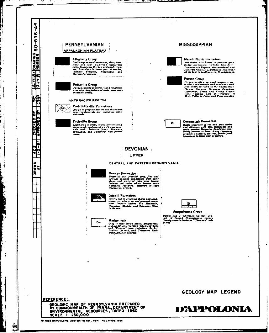
Colver Dam physiographically lies within the Allegheny Mountains sectionF, of the Appalachian Plateau Province. The dam site is on the west flank
of the Laurel Hill anticline, which coincides with the east flank of theBarnesboro syncline in this area. The strata dip approximately 150 feetper mile to the west. Bedrock at the site consists of sedimentary rockstrata of the Middle to Lower Conemaugh Group of the Pennsylvania Series.In general, strata of the Conemaugh Group consist of interbedded shale,claystone, sandstone, and several thin coal seams. The underlyingAllegheny Group consists of sandstone and shale strata along with
several seams.
The slopes in the vikinity of the reservoir are relatively gentle,reflecting the ease of weathering of the fine-grained Conemaugh rock
strata. No large slides should occur, although minor creep may beexpected. I
ifi
Ideal fea
C.u
me I
pi Avon cc
sun Cove SDom ~i
fc creak
Cronsa Mlasniii
-SCALEL~rll
* EFRE Cot GEO OG MAPo¶ I EOLGICMAP F PNNSLVANA PEPAEDt
- ~ ~ ~ ~ I ho SYA COMNELHO-%NA.EATETOPI 3 3 1 1 N
* I ~ '. SCALE 0250,00-c PCss ~s~u, * ~w- ew A~ts,
a~P ueI-sirvi1
In~
oPENNSYLVANIAN MISSISSIPPIANco APPALACHIAN PLATEAU
amr -Allegheny Group Mauch Chunk Formation42Cwelfeeiquo'"roeeerfmariesom. stores. time. Pero ahbsta wth~f brown to, sor rrtnk prowt
*#-". laical Met: nuamerous commercial fineew -edoiooo t,,,r.Iurlrri h.,ems"I: lm~eMoves A Iih rrhi westward: Vall- I lMm dm i nliiI A'cpftti. Wretmoreland. motor
OZport Limestone iwlne. roomir lat of oir,440: Somerset e~auti,e. l.,iwawlhromiiu I.mienowiiueoludee preeperi. Kittanning. amid mhat the bo in umtmhowsreIA.ru PreugI"u.clarimPer i'rm"""e..
6 Pocono Group
Pottsville Group t,1,,d relmrto "4 euet withW"ff sthool inch uds!. to, lb.. Appmahaehmu.
PredomicuutiwV .ucdatioth n d mouliona.flt"ptom kne. owmortdeam with this shot wee malsd mim towsa Ruemp-. ~uuiii UMmineable lmemur. ~ wccCorry. died Xnpp Poprui'a,
H N.L. Pallid is Feff.. mud ?lm eeuulit'
ANTHRACITE REGION
Post-Pottsville FormationsPreuoo or prp mindelnr . aaneo, More. with
oome M ovr t m, imr.a ie- Pottsville Group 'h7]Canemaugh FormastionLight prew to whbite. -rcie r.. sto~.4 owed- Cridie 0e-ea ci - o d and prop ae.etnvt a. d mud erueemiiatr with some mime mud sedsmecr eisih this Uuiemwon andable -snSelvd~s shairp htsountotia crew umeelme Mmboomulu sawdefoome Com-Rehurtkhill &ud rambling Ran irorma. .#uw preeulat no bow Anowee Limm1eu
rwlI iddene e C cioraee: Bir" Covee
J~eu PwSeerepr .mefooeis.
DEVONIAN
UPPER
z CENTRAL AND EASTERN PENNSYLVANIA
CWI09atalil Formationonfifl rmind I. honwlenswih m ineec e mdOates aeuiew.ate. r m ifeedwed ~ msioeeadai.s'O exahlti whch Da argo"senumleru amag. r. astsm ofog
Down"quehaenPrGreup
Catskel FormaCtion Cheal .w
J Ofl red f to slswe states anedm eemind.a?
ae l'ara o ra and in ieu c m osdur -
'Honesdale.fShrkoes. and Detntion RierltTulkio a~mi.lo.1hm
Suqean4ru
GEOLOGY MAPe LEGENDot Ctkil Cn4~ELOI toAP OF PENNSLVANd PREPAREDs aro
BYin COMOWELT OFo PENA. DEPARTMEN OFDbo era'ChoroNI
S~~~.i gagaooP. eaemeuguhoffun. beds @. it. ALSIOI?