Embed Size (px)
Citation preview

1
Date Distributed: June 26, 2019
NATIONAL BOARD SUBCOMMITTEE
REPAIRS AND ALTERATIONS
AGENDA
Meeting of July 17th, 2019
Kansas City, MO
The National Board of Boiler & Pressure Vessel Inspectors 1055 Crupper Avenue
Columbus, Ohio 43229-1183 Phone: (614)888-8320 FAX: (614)847-1828
2
1. Call to Order 8:00AM
2. Introduction of Members and Visitors
3. Announcements The National Board will be hosting a reception for all committee members and visitors on Wednesday evening at 5:30pm in the Rooftop Ballroom on the top floor of the InterContinental. Service Award Pins:
Wayne Jones – 10 years 4. Adoption of the Agenda
5. Approval of the Minutes of the January 16th, 2019 Meeting
The minutes are available for review on the National Board website, www.nationalboard.org.
6. Review of Rosters (Attachment Page 1) a. Membership Nominations
i. Patricia Becker – SC Repairs and Alterations (Interest Category – Manufacturer) ii. Michael Quisenberry – SC Repairs and Alterations (Interest Category – Certificate Holder)
iii. John Siefert – SC Repairs and Alterations (Interest Category – General Interest) iv. Paul Shanks – SG & SC Repairs and Alterations (Interest Category – AIA) v. Tim McBee – SG & SC Repairs and Alterations (Interest Category – AIA)
vi. Robert Underwood – SG Repairs and Alterations (Interest Category – AIA) vii. Nolan Lee and Richard Bulgin – SG Graphite
viii. John Eihusen, Brian Linnemann, Allen Beckwith, and Bill Holtzlaw – SG FRP b. Membership Reappointments
i. Mr. Jim Pillow and Mr. Ray Miletti both have memberships to SC R&A that expire on 7/31/2019.
ii. Mr. Francis Brown and Ms. Debra McCauley are up for reappointment to Subgroup FRP. Their reappointments were approved by a vote at the subgroup level.
iii. Mr. Linn Moedinger and Mr. Matthew Janssen are up for reappointment to Subgroup Locomotive.
iv. Mr. Francis Brown and Mr. Justin Clemens are up for reappointment to Subgroup Graphite. Their reappointments were approved by a vote at the subgroup level.
c. Officer Appointments i. SG Locomotive will be electing a new Chair and Vice Chair at their meeting.
7. Interpretations Item Number: 17-143 NBIC Location: Part 3 No AttachmentGeneral Description: Can an "R" stamp certified shop manufacture and use parts for use on the pressure boundary to complete the repair of a boiler? Subgroup: Repairs and Alterations Task Group: Paul Welch (PM), Linn Moedinger Nazo January 2019 Meeting Action: Progress Report: Mr. Moedinger gave a progress report that work is still being done on the item and it will be put out to Letter Ballot to Repair and Alteration SG.

3
Item Number: 18-34 NBIC Location: Part 3, 8.4 No AttachmentGeneral Description: Does an R certificate holder assume responsibility for safety/integrity of a vessel outside the scope of repair? Subgroup: Repairs and Alterations Task Group: Nathan Carter (PM(, Michael Quisenberry January 2019 Meeting Action: Progress Report: Mr. Nathan Carter reported that the Task Group is awaiting comment from the National Board’s legal representation on this Item.
Item Number: 18-53 NBIC Location: Part 3 Attachment Page 22General Description: Is changing the corrosion allowance noted on the original Manufacturer’s Data Report considered an alteration per NBIC, when this task is performed solely for the purpose of establishing minimum required thicknesses on an internal Owner / User mechanical integrity database? Subgroup: Repairs and Alterations Task Group: Brian Boseo (PM) January 2019 Meeting Action: Progress Report: Mr. Boseo presented that there has been no response from the inquirer for more information. Mr. Boseo stated that one more attempt will be made to request more information, and if no response is received by the July 2019 meeting, this item will be closed.
New Interpretation Requests:
Item Number: 19-4 NBIC Location: Part 3, 3.2 Attachment Page 23General Description: Use of Different Editions of the Construction Code for Repair or Alteration Subgroup: Repairs and Alterations Task Group: None Assigned. Explanation of Need: Try to resolve if there should be a restriction to different editions of the code of construction.
Item Number: 19-5 NBIC Location: Part 3, 3.2.6 Attachment Page 24General Description: Reference to Other Codes and Standards Subgroup: Repairs and Alterations Task Group: None Assigned. Explanation of Need: Repair Methodology proposed by user is rejected by AI as there are no codes, standards, and practices available to support repair method.
4
Item Number: 19-10 NBIC Location: Part 3, Introduction, paragraph on
Interpretations
Attachment Page 26
General Description: Allow interpretations to be used in any edition, provide the same wording Subgroup: Repairs and Alterations Task Group: None Assigned. Explanation of Need: NBIC currently limits each interpretation to the edition it was issued for. However often time the words in question do not change from one edition to another. At present a new interpretation would be needed for each edition of the NBIC to address the same issues, this is a delay to field work and a drain on NBIC committee time.
Item Number: 19-17 NBIC Location: Part 3, S1.2.11.3 Attachment Page 27General Description: Wastage at Mudring: If the majority of the wastage is on the fireside, and there minimal wastage on the waterside, does this section still govern repairs? Subgroup: Locomotive Task Group: None Explanation of Need: This question is in regards to a CFR 230, 1472 day boiler inspection on a 1927 built Baldwin 4-8-4 steam locomotive. The door sheet (aka back sheet) in the firebox has sustained wastage at the mudring on the fireside, caused by the proximity of the firebrick. In the figure S1.2.11.3, the drawing indicates a wastage on the waterside, yet the text of section S1.2.11.3 does not specify if it is referring to the waterside, the fireside, or both. Please see attached diagram of the wastage in question.
Item Number: 19-20 NBIC Location: Part 3, 3.3.4.2 e) Attachment Page 29General Description: Use of Heli-Coils for repairs and alterations of PRI's Subgroup: Repairs and Alterations Task Group: None Assigned. Explanation of Need: Paragraph 3.3.4.2e) states that defective bolting shall not be repaired but shall be replaced with suitable material that meets the specification of the original code of construction. When a bolt head is broken off leaving the bolt threaded in the RPI, a Heli-Coil is normally used to fix the problem. The problem with a Heli-Coil, is that there types made of different materials. NBIC requires material used to be in accordance with the Code of Construction. Also, needed to be taken into consideration would be threading calculations to verify acceptable pressure retention of the RPIs MAWP.
5
Item Number: 19-25 NBIC Location: Part 3, 4.4.2 c) Attachment Page 30General Description: NDE methods to do in lieu of Hydro test Subgroup: Repairs and Alterations Task Group: None Assigned. Explanation of Need: For ASME BPV Section VIII Division 2 Vessel is under Alteration with Re-rate of lowering MAWP & increasing of Design Temperature & there is no physical alteration in the Vessel but only change is in the Alteration design report because of different design stress intensity value at higher design temperature.
Item Number: 19-26 NBIC Location: Part 3, 3.3.2 Attachment Page 31General Description: Clarification on welding repairs on appendages Subgroup: Repairs and Alterations Task Group: None Assigned. Explanation of Need: The original submitter of this item will sometimes need to perform a welding repair on an appendage (not on the tank itself) in order for the complete process of refurbishment to be done for their customers’ expectations. There appears to be no direct reference to these types of minor welding repairs for the refurbishment process in the NBIC code.
Item Number: 19-34 NBIC Location: Part 3, 3.2.2 e) Attachment Page 32General Description: Is it the intent of Part 3, 3.2.2 e) that the reference to the original code of construction is for determining the hydrostatic test pressure? Subgroup: Repairs and Alterations Task Group: None Assigned. Explanation of Need: NBIC Part 3 Section 3 paragraph 3.2.2 e) (shown below) states that replacement parts shall receive a pressure test as required by the original code of construction. The original submitter is concerned that this clause is not being interpreted consistently by all users of the NBIC. The words in question are “…as required by the original code of construction.” ASME issued interpretation I-16-1 (shown below) and revised PW-54 to clarify that Section I does not contain requirements for the hydrostatic testing of replacement parts provided for an existing unit. Based on this, the words “… as required by the original code of construction.” Could be interpreted to mean that pressure testing of the parts is not required because Section I does not require testing of replacement parts. The submitter does not think that was the Committee’s intent when clause e) was added to 3.2.2. Linking the words “original code of construction” to the test pressure would eliminate the potential interpretation that testing is only required when the original code of construction specifically requires testing of replacement parts.

6
Item Number: 19-35 NBIC Location: Part 3, 2.5.2 and 3.4
Attachment Page 35
General Description: POST WELD HEAT TREATMENT- ALTERATION-Part 3- 3.4 & 2.5.2 Subgroup: Repairs and Alterations Task Group: None Assigned. Explanation of Need: An R Certificate Holder is Doing Repair Work on the Shell Side of Heat Exchanger, which was not PWHT Earlier. As per Client Request, Welded Joints are Post weld Heat Treated and Consider as Alteration, Client wants Shell Side to Under Go Full Post weld Heat Treatment Including areas not repaired. NDE is being Carried out for Complete Equipment and Client wants PWHT for Welds which are in Services and without any repairs.
Item Number: 19-36 NBIC Location: Part 3, 3.3.2 &
3.3.5 Attachment Page 36
General Description: Routine Repairs of VIII Div 2 and Div 3 PV Subgroup: Repairs and Alterations Task Group: None Assigned. Explanation of Need: Para 3.3.2 talks about requirements for and examples of routine repairs. It does not specify any restrictions on pressure retaining items construction Code. It states that Routine repairs are repairs for which the requirements for in-process involvement by the Inspector and stamping by the “R” Certificate Holder may be waived as determined appropriate by the Jurisdiction and the Inspector. It states that all other applicable requirements of this code (NBIC) shall be met. Para 3.3.5.1 of NBIC states that the following requirements shall apply for the repair of pressure vessels constructed to the requirements of Section VIII, Division 2 or 3, of the ASME Code. This calls for properly Certified repair plan to be submitted to the Inspector who will make acceptance inspection and sign R-1 Form.
Item Number: 19-42 NBIC Location: Part 3, 3.3.3 s) &
3.4.4 g) Attachment Page 39
General Description: 3.3.3 s design intent clarification vs 3.4.3 g Subgroup: Repairs and Alterations Task Group: None Assigned. Explanation of Need: The design requirement in 3.3.3 s) is not well defined and is allowing potentially unsafe material changes to be conducted as repairs without adequate assessment.

7
Item Number: 19-44 NBIC Location: Part 3, 1.6.6.2,1.6.7.2, 1.6.8.2
Attachment Page 40
General Description: ISO/IEC 17025 Revision Subgroup: Repairs and Alterations Task Group: None Assigned. Explanation of Need: Many, if not all calibration labs are already accredited to ISO/IEC 17025:2017 and will be required to by 2020. No lab will bother accreditation to 2005 after that, so finding a calibration house will be difficult.
8. Action Items
Item Number: NB15-1405 NBIC Location: Part 3, 1.2 Attachment Page 41General Description: Impact testing of P-11B Material Subgroup: Repairs and Alterations Task Group: N. Carter (PM), P. Davis, G. Galanes, P. Shanks History: In January 2015 Mr. Wielgoszinski provided a report. After consideration, Mr. Wielgoszinski decided to withdraw the inquiry (IN14-0401) and requested a new item to address impact testing of P11B material. A motion was made to close this interpretation and open up an action Item. The new action item will be: NB15-1405 Part 3-Impact testing of P-11B Material, (From IN14-0401) This Item has not been included in the minutes or agendas since July 2015. On 01/15/2019, this item was put back on the SG R&A Agenda and a new task group was formed. January 2019 Meeting Action: Progress Report: On 01/15/2019, this item was put back on the SG R&A Agenda and a new task group was formed.
Item Number: NB15-2208 NBIC Location: Part 3 No AttachmentGeneral Description: Develop supplement for repairs and alterations based on international construction standards Subgroup: Graphite Task Group: Greg Becherer (PM) January 2019 Meeting Action: Progress Report: No information was received from Graphite Subgroup at the time of this meeting. No action taken. Update from SG Graphite: A proposal is still in development for this item.

8
Item Number: NB16-1402 NBIC Location: Part 3 Attachment Page 47General Description: Life extension for high pressure vessels above 20 years Subgroup: FRP Task Group: M. Gorman (PM) January 2019 Meeting Action: Progress Report: No information was received from FRP Subgroup at the time of this meeting. No action taken. Update: Item was approved by Subgroup FRP and is awaiting review and approval from the subcommittee.
Item Number: NB16-1403 NBIC Location: Part 3, S4 Attachment Page 52General Description: Add information on repair of high pressure vessels. Subgroup: FRP Task Group: N. Newhouse (PM) January 2019 Meeting Action: Progress Report: No information was received from FRP Subgroup at the time of this meeting. No action taken. Update: This item was approved by SG FRP via letter ballot in June.
Item Number: NB16-1502 NBIC Location: Part 3 No AttachmentGeneral Description: Develop supplement for repairs and alterations based on international construction standards Subgroup: SG Repairs and Alterations Task Group: International Repair Supplement Task Group, Chuck Withers (PM) January 2019 Meeting Action: Progress Report: Mr. Withers was not present and could not present the item. No action taken. Item Number: 17-134 NBIC Location: Part 3, Section 5 No AttachmentGeneral Description: Proposed Revision for registration of Form R-1 with the National Board containing ASME pressure part data reports attached. Subgroup: Repairs and Alterations Task Group: P. Shanks (PM), Rob Troutt, Joel Amato, Kathy Moore, Paul Edwards January 2019 Meeting Action: Progress Report: P. Shanks gave a progress report.

9
Item Number: 17-137 NBIC Location: Part 3, S4.18.2 Attachment Page 55General Description: Remove "sand" blasting and replace with "abrasive" in Part 3, S4.18.2 Subgroup: FRP Task Group: Terry Cowley January 2019 Meeting Action: Progress Report: No information was received from FRP Subgroup at the time of this meeting. No action taken.
Item Number: 17-166 NBIC Location: Part 3, S3 Attachment Page 57General Description: Remove nozzle replacement and tube replacement from graphite routine repair list. Subgroup: Graphite Task Group: Francis Brown (PM) January 2019 Meeting Action: Progress Report: No information was received from Graphite Subgroup at the time of this meeting. No action taken. Update: Item was approved unanimously by Subgroup Graphite at their March 2019 meeting.
Item Number: 17-167 NBIC Location: Part 3, S3.2 d) No AttachmentGeneral Description: Clarify repair inspection requirements for machined only graphite parts. Subgroup: Graphite Task Group: Aaron Viet (PM) January 2019 Meeting Action: Progress Report: No information was received from Graphite Subgroup at the time of this meeting. No action taken. Update: Work is still being done to develop a proposal for this item.
Item Number: 18-12 NBIC Location: Part 3 Attachment Page 58General Description: Adding Weld Buildup to WM #6 Subgroup: SG Repairs and Alterations Task Group: John Siefert PM, George Galanes January 2019 Meeting Action: Mr. George Galanes presented that this Item was opened at the January 2018 meeting and the proposed revision to Welding Method 6 to limit weld build up to 100 square inches on only Grade 91 tubes. A motion was made to put the proposal out to Subgroup Repairs & Alterations and Subcommittee Repairs & Alterations for Review and Comment. The motion was unanimously approved.

10
Item Number: 18-13 NBIC Location: Part 3 Attachment Page 61General Description: Weld Methods 7 addition for dissimilar weld metal-Gr. 91. Subgroup: SG Repairs and Alterations Task Group: John Siefert PM, George Galanes January 2019 Meeting Action: Mr. George Galanes presented that this Item was opened at the January 2018 meeting and the proposed addition of a Welding Method 7. Welding Method 7 is being introduced to permit dissimilar metal weld repair with no PWHT between Grade 91 boiler tubes to austenitic steels and low alloy ferritic steels. This action permits DMW of Grade 91 tubes within the boiler setting following welding method 6 with no PWHT. A motion was made to put the proposal out to Subgroup Repairs & Alterations and Subcommittee Repairs & Alterations for Review and Comment. The motion was unanimously approved.
Item Number: 18-65 NBIC Location: Part 3, Section 3 No AttachmentGeneral Description: Draft rules for “used” material in repairs and/or alterations. Subgroup: SG Repairs and Alterations Task Group: Jamie Walker – PM, Marty Toth, Pat Becker, Michael Quisenberry, Issac Osborn, Paul Shanks, R. Underwood January 2019 Meeting Action: Progress Report: Mr. J. Walker presented a progress report. As a result of Interpretation Item 18-30, the SG decided to open this Item to draft rules for “used” material utilized in repairs and/or alterations.
Item Number: 18-66 NBIC Location: Part 3, Section 5 No AttachmentGeneral Description: Move Report Forms to a new Supplement. Subgroup: SG Repairs and Alterations Task Group: Marty Toth – PM, Ben Schaefer January 2019 Meeting Action: Progress Report: B. Schaefer presented a Progress Report on ongoing work to move the Reports of Repair and their instructions to a new Supplement.
Item Number: 18-75 NBIC Location: Part 3 Attachment Page 65General Description: Flush patches in stayed and un-stayed areas of tubesheets Subgroup: SG Repairs and Alterations Task Group: Michael Quisenberry (PM), Kathy Moore, Marty Toth, Rick Sturm January 2019 Meeting Action: M. Quisenberry presented a revision to Part 3, Section 3, paragraph 3.3.4.6 incorporating verbiage from Supplement 1.2.11.2 for historic boilers to address flush patches and using NDE alternatives to volumetric methods. A motion was made and unanimously approved to have this proposal submitted via Letter Ballot for Review and Comment to Subgroup Repairs & Alterations and Subcommittee Repairs & Alterations.

11
Item Number: 18-84 NBIC Location: Part 3, S1.2.8 No AttachmentGeneral Description: Additional subparagraph in Part 3, S1.2.8 about the use of patch bolts being in accordance with ASME BPVC Subgroup: Locomotive Task Group: (R. Musser – PM) January 2019 Meeting Action: Progress Report
Item Number: 18-85 NBIC Location: Part 3, 2.3 and
Table 2.3 Attachment Page 69
General Description: For the SWPS AWS B2.1-1-233:2006, is the root or 1st pass using GTAW-S (Short Circuiting Transfer mode) allowed to be used in all positions? Subgroup: Repairs and Alterations Task Group: Jim Sekely (PM) Meeting Action: Mr. Sekely presented a revision to the SWPS summary verbiage in Table 2.3, satisfying the Inquirer’s question. The interpretation was withdrawn by the Inquirer (Mr. Terrence Hellman) and a motion was made to have Item 18-85 presented to Subcommittee Repairs & Alterations as an Action Item to approve the proposed revision. The motion was unanimously approved.
Item Number: 18-93 NBIC Location: Part 3, S3.2, S3.4
4.4.2 6) No Attachment
General Description: Test Duration Subgroup: Graphite Task Group: J. Clements (PM) January 2019 Meeting Action: Progress Report: No members from the Graphite Subgroup were present at the time of this meeting. No action taken. Update: Work is being done to develop a proposal for this item.
Item Number: 18-94 NBIC Location: Part 3, S3.2 f), h);
S3.4 a), b), c) etc. No Attachment
General Description: G-mark Requirements for Various Repairs/Alteration to Graphite Subgroup: Graphite Task Group: C. Cary (PM) January 2019 Meeting Action: Progress Report: No members from the Graphite Subgroup were present at the time of this meeting. No action taken. Update: Work is being done to develop a proposal for this item.
12
Item Number: 18-95 NBIC Location: Part 3, S1.1.4 No AttachmentGeneral Description: Revision to Part 3, S1.1.4 to account for new rules for riveted construction Subgroup: Locomotive Task Group: (L. Moedinger – PM) January 2019 Meeting Action: Progress Report: Mr. Moedinger presented work is still be done on this item. No action taken.
Item Number: 18-100 NBIC Location: Part 3, 3.3.2 Attachment Page 70General Description: Revision adding heat exchanger tubes with an outside diameter of ¾” or smaller to NBIC Part 3.3.2 Routine Repairs Subgroup: Repairs and Alterations Task Group: (David Martinez – PM), B. Schaefer, N. Carter January 2019 Meeting Action: Progress Report: Mr. Martinez reported on a this item and presented interpretations (98-04 and 98-29) that may satisfy the revision request, however after a presentation from TEiC regarding the use of explosive welding of tubes to be considered as a routine repair, Mr. Martinez recommend this be considered progress report to continue working to address explosive welding as a Routine Repair.
Item Number: 18-102 NBIC Location: Part 3, Table 2.3 Attachment Page 82General Description: Revise Table 2.3 in Part 3 to add the listed SWPSs that were revised by the AWS B2 Committee in 2018 Subgroup: Repairs and Alterations Task Group: (Jim Sekely – PM) January 2019 Meeting Action: Progress Report: Mr. Sekely presented a proposed addition of 8 SWPS into Table 2.3 that were revised by the AWS B2 Committee in 2018. After discussion, there was confusion regarding the formatting of the submitted revision. Mr. Sekely agreed to submit this as a Progress Report to allow formatting and metrification changes to be addressed prior to next meeting.
New Items:
Item Number: 19-11 NBIC Location: Part 3, 9.1 Attachment Page 99General Description: Clarify Definition of Authorized Nuclear Inspection Agency (ANIA) Subgroup: Repairs and Alterations Task Group: None assigned Explanation of Need: An ANIA cannot be an Inservice AIA since Endorsements for nuclear inspectors are issued only to new construction AIA’s. The requirements for qualified Authorized Nuclear Inspectors/Supervisors are clearly specified in NB-263, RCI-1. Therefore revision to the Glossary definition is needed to clarify this requirement for the NR Accreditation Program.
13
Item Number: 19-12 NBIC Location: Part 3, 1.6.3 b) Attachment Page 100 General Description: Paragraph 1.6.3 – revise text to clarify Quality Assurance Program reqs Subgroup: Repairs and Alterations Task Group: None assigned Explanation of Need: Revise text to clarify Quality Assurance Program requirements for NR Cert holders.
Item Number: 19-13 NBIC Location: Part 3, 1.6.6.2 s),
1.6.7.2 s), & 1.6.8.2 s) Attachment Page 101
General Description: Revise text to clarify responsibilities for performing audits Subgroup: Repairs and Alterations Task Group: None assigned Explanation of Need: Revise text to clarify responsibilities for performing audits between the Certificate Holder and the AIA.
Item Number: 19-15 NBIC Location: Part 3, 3.3.5.2 a) Attachment Page 102General Description: ASME Section VIII Division 2 Class 1/Class 2 Distinction Subgroup: Repairs and Alterations Task Group: None assigned Explanation of Need: Engineering certification for repairs is an unnecessary cost when engineering certification is not required by the original code of construction.
Item Number: 19-16 NBIC Location: Part 3, 3.3.2 e) Attachment Page 103 General Description: Reword to provide clarity; contradictory requirement Part 3; 3.2.2 e) Subgroup: Repairs and Alterations Task Group: None assigned Explanation of Need: This wording of this clause is causing confusion. The original submitter has had multiple instances where owners have requested to purchase welded replacement parts directly and read this clause with the belief that they can purchase a replacement part for in some cases a welded pressure part for an ASME Section I boiler and safe money by having the fabricator not Hydro test as per Section I even when it was not impractical to have the testing performed.

14
Item Number: 19-19 NBIC Location: Part 3, S4.2 Attachment Page 104 General Description: Reword to provide clarity; contradictory requirement Part 3; 3.2.2 e) Subgroup: FRP Task Group: None assigned Explanation of Need: The current use of the term "inspector" in S4.2 does not mean a Commissioned Inspector as defined in Section 9. Clarification is needed. Update: A proposal is in development for this item.
Item Number: 19-21 NBIC Location: Part 3, S2.11 a) Attachment Page 106General Description: Additional wording to S2.11 a). Explanation of Need: The changes in the proposal were made in a document passed by SG Historical in July 2018, and somehow left off of the document that was submitted to R&A and to MC. Subgroup: SG Historical Task Group: None assigned
Item Number: 19-24 NBIC Location: Part 3, S6.16.4 b)
1) Attachment Page 107
General Description: Supplement 6 to record the "R" number assigned to either R-1 or R-2. Subgroup: Repairs and Alterations Task Group: None assigned Explanation of Need: Paragraph S6.16.4 b) 1) currently only requires "R-1" forms to be registered with the National Board, however the paragraph should be for EITHER R-1 Forms OR R-2 Forms.
Item Number: 19-27 NBIC Location: Part 3, S2.13.14.3-a No AttachmentGeneral Description: Fusible Plug Repair Using Half Coupling Figure Subgroup: SG Historical Task Group: None assigned
Item Number: 19-31 NBIC Location: Part 3, Table 2.3 Attachment Page 108 General Description: Part 3 - Table 2.3 - Thickness Range Corrections Subgroup: Repairs and Alterations Task Group: None assigned Explanation of Need: Thickness listed in Table 2.3 had different values than the AWS Standards.
15
Item Number: 19-32 NBIC Location: Part 3, 3.3.2 & 3.4.4
Attachment Page 113
General Description: Heater treater and or re-heater fire tubes Subgroup: Repairs and Alterations Task Group: None assigned Explanation of Need: When heater treaters and some other similar equipment is constructed in accordance with section VIII div.1 an item called a fire tube is often removable (bolted) and should be part of the code boundary. In use these items are consumables and are replaced often with items not bearing the code markings or manufactured to code practices. This practice places the users and public in jeopardy and should be curtailed.
Item Number: 19-43 NBIC Location: Part 3, 1.6.6.2,
1.6.7.2, & 1.6.8.2 Attachment Page 116
General Description: ISO/IEC-17025 Edition referenced in NR Section of Part 3 Subgroup: Repairs and Alterations Task Group: None assigned Explanation of Need: References to "ISO/IEC-18025:2005" need to be changed to "ISO/IEC-18025:2017" to align with ASME Section III requirements in the following paragraphs: 1.6.6.2 m) 1), 1.6.6.2 m) 4) a), 1.6.6.2 m) 5) a), 1.6.7.2 m) 1), 1.6.7.2 m) 4) a), 1.6.7.2 m) 5) a), 1.6.8.2 m) 1), 1.6.8.2 m) 4) a), and 1.6.8.2 m) 5) a)
Item Number: 19-47 NBIC Location: Part 3, 1.5.1 k) No Attachment General Description: Specify Welding, NDE and Heat Treatment requirements in 1.5.1 of Part 3 Subgroup: Repairs and Alterations Task Group: None assigned Explanation of Need: The Quality Control Elements of "welding, NDE, and Heat Treatment" need to have clear controls. Currently the paragraph really only references welding. NDE and Heat Treatment are only referenced by the last sentence in the paragraph, "Similar responsibility for nondestructive examination and heat treatment shall be described in the manual." Minimum controls or requirements for NDE or Heat Treatment need to be expressed in order for these elements to be auditable.
Item Number: 19-48 NBIC Location: Part 3, 1.5.1 l) &
m) No Attachment
General Description: Calibration, Examinations and Tests - 1.5.1 of Part 3 Subgroup: Repairs and Alterations Task Group: None assigned Explanation of Need: A review of all QC Elements in Section 1.5.1 in Part 3 of the NBIC needs to be done to verify that auditable controls and minimum requirements are understood and referenced within an "R" Cert. Holder's Quality System.
16
Item Number: 19-50 NBIC Location: Part 3, 3.3.4.3 e) 3) l)
Attachment Page 118
General Description: Revising Part 3, 3.3.4.3 e) 3) l) to match rules of ASME PCC-2 Subgroup: Repairs and Alterations Task Group: None assigned Explanation of Need: There are a couple of typos in the paragraph as it does not match up with the rules of ASME PCC-2 for External Weld Metal Buildup.
Item Number: 19-52 NBIC Location: Part 3, 4.2 a) Attachment Page 119 General Description: Part 3, Section 4 - 4.2 a) Alternative NDE requirements Subgroup: Repairs and Alterations Task Group: None assigned Explanation of Need: Clarification is needed that if alternative NDE methods acceptable to the Inspector and Jurisdiction meet ALL the requirements listed elsewhere in Section 4 of Part 3. New verbiage is adding ", provided all other requirements of this section are met." to the last sentence.
Item Number: 19-53 NBIC Location: Part 3, S2.12 Attachment Page 120General Description: External Pressure Subgroup: SG Historical Task Group: None assigned Explanation of Need: Supplement 2 does not sufficiently address record retention as required by Part 3, 1.5.1(t).S2.12 states that owners "should" retain permanent records, but it is not mandatory. Paragraph 1.5.1(t) and Table 1.5.1 require all records be retained for 5 years.
9. Future Meetings
January 13th -16th, 2020 – San Diego, CA
July 13th-16th, 2020 – Louisville, KY 10. Adjournment
Respectfully submitted,
Terrence Hellman SC Repairs and Alterations Secretary
ContentsSC 3 July 19 Meeting Roster 1Resume_PatBecker 2MJQ Resume 3Siefert_John-3 6Paul Shanks Resume 16Tim Resume 2019 19INT - Item 18-53 22INT - Item 19-4 23INT - Item 19-5 24INT - Item 19-10 26INT - Item 19-17 27INT - Item 19-20 29INT - Item 19-25 30INT - Item 19-26 31INT - Item 19-34 32INT - Item 19-35 35INT - Item 19-36 Routine Repair of VIII Div 2 and Div 3 PV 36INT - Item 19-42 39INT - Item 19-44 40NB15-1405 revision to NBIC - history (2) 41Item NB16-1402 4-23-2018 MC 47NB16-1403-190514 52SG FRP Item 17-137 55Record 17-166 57Item 18-12 - Siefert - rev 3 58Item 18-13 - Siefert - rev 3 61Item NB18-75 - Quisenberry 65Item 18-85 - Sekely - 1-16-19 69Item 18-100 70Item 18-102 - Sekely - Proposed Changeto Table 2.3 (SWPS Update) (1) (2) 82Item 19-11 - Withers - 01-22-2019 - ANIA Definition revision 99Item 19-12 - Withers - 01-22-2019 - QAP Reqs 100Item 19-13 - Withers - 01-22-2019 - NR Audit Requirements 101Item 19-15 102Item 19-16 103Item 19-19 - Hellman - 03-06-2019 104

Item 19-21 106Item 19-24 107Item 19-31 - SWPS Revisions - Hellman - 04-09-19 108Item 19-32 113Item 19-43 - ISO-17025 - 2005 to 2017 - Hellman - 6-11-19 116Item 19-50 118Item 19-52 - Hellman - 6-25-2019 119Item 19-53 S2.12 Record Retention 120

1

Patricia Becker Pressure Vessel Design Engineer
AREAS OF EXPERIENCE Codes & Standards: Pressure Vessel Engineering & Design ASME BPV Codes & Standards (SG Committee Member) NBIC (Nat’l Board Inspection Code) Advisory Committee MemberB&W Internal Standards (Code SME)
Manufacturing: Pattern Equipment (for Steel Castings) Machining Jigs & Fixtures Design Fabrication Solutions & Support
Pressure Part Engineering & Design Engineering SpecificationsEstimating Proposal Preparation Pressure Part Calculations Fabrication & Mfg Drawings Mentoring & Training Weld Schedules Familiarity and use of related programs including, PLM, Compress, Solidworks, AutoCAD, Microsoft Excel, Word, Powerpoint, Outlook, etc.
Quality Control: Standards Development & Preparation Checking of Mfg Drawings & Specifications ASME Audit Preparation including Quality Manual Content Support
Conference Participation ASME, EPRI, NBIC, PVP
PROFESSIONAL MEMBERSHIP
ASME Boiler Pressure Vessel Code AWS (American Welding Society)
PERSONAL SKILLS
Self-Motivated Problem Solver Mentor/Teacher Good Communicator Hard Worker
PERSONAL DETAILS Patricia Becker 3135 Oser Rd. Norton, OH 44203
T: (330) 825-8735 C: (330) 294-8247 E: [email protected] W: (330) 860-2807
Barberton, OH WORK HISTORYEngineering - The Babcock & Wilcox Co. PRESSURE VESSEL DESIGN ENGINEER 2006-Present
Responsibilities Include: Header & Drum Design for new and replacement pressure part related components ASME compliant Calculations, Engineering drawings and Fabrication Specifications Process improvement activities related to PVE, Standards Support & Development Pressure Part Project experience including checking Engineering & Mfg. Releases Represent B&W as a member of Section I on the Boiler & Pressure Vessel Code
SG General Requirements & Piping and SG Fabrication & Exam. Also a Member ofthe National Board Advisory Committee.
QA and peer support, answering questions related to all aspects of pressure partreleases including Code & Standards Compliance, and PVE programs.
Manufacturing - Anger Pattern Inc. Canal Fulton, OH PATTERNMAKER 1999-2004
Supervision and Training of apprentices, building of pattern equipment. Checked, estimated, quoted and supported all facets of shop functions including
developing problem solving solutions for manufacturing issues.Manufacturing - American Pattern & Machine, Inc. Barberton, OH PATTERNMAKER 1990-1998 2004-2006
Built Pattern Equipment and gating. Managed shop work load and training ofapprentices including defining/developing apprentice program.
Foundry support, mold planning/gating, layouts, checking, inspection and qualitymanagement. Customer relations and liaison between engineering and shop.
Manufacturing - Welch Pattern, Inc. Barberton, OH PATTERNMAKER 1983-1989
Part owner/operator of a family-run business. Patternmaker for steel casting industry. Building pattern equipment, quoting and
estimating, accounts payable and receivable, training of apprentices.
EDUCATION Stark State College of Technology 2003-2006 Associates of Applied Design Engineering Technology Akron University Studied 1982-1984 English (Honors) Apprenticeship/Journeyman Patternmaker 1982-1985
REFERENCES (References Available Upon Request)
PERSONAL SUMMARY Hard working with good communication and organizational skills. Self-motivated with a strong attention to detail and keen interest in learning and expanding knowledge base related to all areas affecting inherent duties and responsibilities. Driven by a desire to provide on time, safe, and effective solutions for engineering and manufacturing challenges. Experienced in collaborative efforts including key Code and Standard developments with an aim of providing innovative, yet practical guidance, including consideration of ‘real’ life influences and limitations. Desire to work on improvements affecting product quality, consistency, and cost. Proficient in roles requiring decision points based on gathering and weighing technical information, peer input, and probable outcome. A Teacher at heart, determined to pass on knowledge and pertinent information affecting the longevity of a role or position; often asked to train and/or work with less experienced co-workers. Always interested in positions which will afford an opportunity to make a difference...
2
Michael J. Quisenberry 806.316.7174 6117 Yale St. Amarillo, TX 79109 [email protected]
Education: West Texas A&M University Canyon, TX
~ Bachelor of Business Science in Finance
~ Bachelor of Business Science in Economics
Pi Gamma Mu Honor Society (Economics)
Omnicron Delta Epsilon Honor Society (Finance)
Qualifications: Microsoft Office Certified (Extensive Experience with Excel, Word, and Power Point)
Experience working in manufacturing and building trades environment
Skilled in managing employees and delegating responsibilities
Adept in sourcing equipment and materials and issuing / tracking purchasing documentation
Extensive Project Management experience with a focus on repair / maintenance jobs
~ Tradesman Limited Plumbing License – State of Texas
~ Texas State Certified Class III Water Treatment Specialist
Experience: Allen’s Tri-State Mechanical, Inc Deputy Division Manager – Boiler Division
Manage crew of plumbers, pipefitters, and welders. Work in a division that
focuses on serving large commercial, industrial, and institutional mechanical
systems. Extensive knowledge in steam plant piping and design; intimately
familiar with Scotch Marine Boilers, packaged water-tube boilers, and ancillary
boiler room equipment. Knowledgeable in domestic potable water piping, closed
loop systems, condensate return systems, air handler units (AHU’s) and roof top
units (RTU’s). Extensively experienced in water treatment systems such as water
softeners, Reverse Osmosis (RO) machines, carbon filters, green sand filters, and
sediment filtration.
Bid and quoted schedule work for customers on a regular basis, always coming in
on budget. Manage large teams of technicians to respond to unscheduled and
emergency repairs. Coordinate subcontractors, material procurement, labor
schedules, and out of town travel accommodations (i.e. per diem, lodging, and
travel expenses)
ASME /NBIC Code Welding Quality Control Manager
Manage crew of NBIC and ASME qualified code welders who repair and alter
ASME rated pressure vessels. Developed from the ground up and implemented
new quality control program with certified manual. Conducted and passed Joint
Reviews from both the National Board of Boiler and Pressure Vessel Inspectors
(NBIC) and the American Society of Mechanical Engineers (ASME). Currently a
sitting committee member of the National Board Code Committee which develops
3
and implements new legislation for construction, repair, and alteration of boilers
and pressure vessels.
Plains Plumbing Co., LLC Amarillo, TX
Purchasing Agent / Service Manager
Source and procure materials for construction and service jobs. Maintain relationships
with numerous vendors in the manufacturing and building trades industries. Proactively
search for best prices and anticipate needs of the company to perform upcoming work.
Schedule work to be performed for customers and dispatch service technicians to
jobsites. Ensure that projects meet deadlines and expected budgetary constraints.
Tradesman Limited Licensed Plumber
Managed crew of men in bid project work as well as service and repair work on piping
and large mechanical systems. Worked primarily on steam and domestic potable water
applications in large commercial, industrial, and institutional applications. Took
rotational on-call schedule with other technicians and ensured that jobs came in on time
and within budget.
Plumber’s Apprentice
Worked various Journeyman plumbers in plan built construction, design build
construction, and service and repair capacities. Learned fundamental principles of
plumbing and pipefitting. Became knowledgeable in all manner of mechanical systems
including engineered equipment such as SMFT boilers, centrifugal chillers (screw &
scroll), closed loop piping systems, water treatment equipment, and both process heating
and cooling as well as environmental.
Ruby Tequila’s Mexican Kitchen Amarillo, TX
Assistant Manager
Oversaw staff of over 50 employees. Managed day to day financials of the company.
Responsible for anticipating inventory needs and ordering accordingly. Learned to
develop and foster relationships with individuals to increase revenues for the company.
Leal’s Mexican Restaurant Amarillo, TX
Bar and Assistant Manager
Responsible for anticipating the needs of the bar area and ordering inventory as needed.
Managed small staff of 3-5 bartenders and shift scheduling. Developed new recipes for
the bar and supplemented other management staff when needed.
4

Michael J. Quisenberry 806.316.7174 6117 Yale St. Amarillo, TX 79109 [email protected]
References: Simmie Callahan ERAC Services
110 S Ong St.
Amarillo, TX 79106
806-679-6450
Supervisor - 8 years Gary Guinn Energy Service Project Manager
DOE and DOHS Security Clearance
Noresco / Pantex
6203 Rutgers
Amarillo, TX 79109
806-336-4281
Business Associate & Friend, 10 years
Dr. Anne Macy Professor in the College of Business
West Texas A&M University
2501 4th Ave. CC 215C
Canyon, TX 79016
806-651-2523
Former Professor, 3 years
Libby Leal General Manager
Leal’s Mexican Restaurant
1619 S Kentucky
Amarillo, TX 79102
806-444-6860
Manager - 2 years
5

John A. Siefert [email protected]
Home Contact Information: Work Contact Information: 13104 Serenity St. 1300 West W. T. Harris Blvd. Huntersville, NC, 28078 Charlotte, NC, 28262 (704) 804-4579 (704) 595-2886
OBJECTIVE Welding engineering occupation applying hands on problem solving, leadership, and teamwork skills; no geographic limitations EDUCATION
The Ohio State University, Columbus, OH Graduation Date: March 16, 2008 Bachelor of Science in Welding Engineering GPA upon Graduation: 3.24 Loughborough University, Leicestershire, United Kingdom Graduation Date: March 2019 Doctor of Philosophy through the Department of Materials First year report approved July 2016 Second year report approved 2017
EXPERIENCE
Electric Power Research Institute (EPRI), July 2011 – Present Principal Technical Leader – responsibilities include managing approximately ten projects per year through Program 87 Fossil Materials and Repair, Technology Innovation and Supplemental Projects. Project execution includes conducting and coordinating efforts within EPRI using facilities such as the machine shop, metallography lab, welding lab, heat treatment lab and generation lab. Contractors are utilized when EPRI facilities or expertise are not available to properly complete a given project; coordination with contractors includes interaction with testing labs (i.e. destructive evaluation), universities, independently employed individuals and engineering-based organizations. Project management skills also required included budgeting, reporting, task layout of projects with key goals and objectives, planning/road-mapping, basic knowledge of SAP, reporting of results to membership, etc.
1. Program 87 Fossil Materials and Repair – Program 87 assists membership organizations in the welding, corrosion, high temperature behavior and characterization of fossil fired power plant materials. Within this program, responsibilities are generally focused in the management of day to day welding activities and coordinating projects within EPRI’s state-of-the-art facilities. Past projects and efforts include: development of EPRI P87 filler metal, assembling the creep strength enhanced ferritic welding guide, leading the effort to address innovative report delivery in the form of a specialized web application, residual stress examination in bainitic and martensitic creep strength enhanced ferritic (CSEF) steels, and assessing the weldability of advanced stainless steels.
2. Technology Innovation – Technology Innovation provides EPRI membership with long-term research and development separate from the efforts in the base programs. Past projects include the examination of wear behavior of candidate Co-free hardfacing materials, assessing the integrity of powder metallurgy and hot isostatic pressed (PM/HIP) components for stainless steel 316L and CSEF steel Grade 91, materials scouting for EPRI Materials Strategic Program, behavior of 10-12Cr high oxidation resistant CSEF steels in creep, stress relaxation cracking behavior across multiple alloy systems and dissimilar metal welds between ferritic and austenitic stainless steels.
3. Supplemental Projects – Supplemental projects are established at EPRI to involve non-traditional members in critical projects and provide a second funding mechanism in the case that insufficient funds are available in a base program. There has been substantial participation and coordination in several projects including: Weld Repair of Grade 91 Piping and Components; Life Management of Boiler and Piping Components fabricated from Grade 92 Steels; Non-Destructive Methods for Detection of High-Temperature Damage in Creep Strength Enhanced Ferritic Steels and Cracking and Disbonding of Hardfacing Alloys in Combined Cycle Plant Valves and Weld Repair of Conventional CrMo Steels to New Code Requirements. Managed several projects including: Tempering Behavior and Characterization of Grades 23/24 Steels; and Application of Well-Engineered Weld Repairs for Grade 91 and other Creep Strength-Enhanced Ferritic (CSEF) Steels.
4. DOE-sponsored Projects – In rare cases, EPRI will submit proposals for government funding. One such project, “Optimization of Advanced Steels for Cyclic Operation through an Integration of Material Testing, Modeling and Novel Component Test Validation” involved the project management and coordination of ~$900k in funding across three institutions in the 2015 to 2018 timeframe.
6

Babcock and Wilcox Research Center (BWRC), April 2008 – June 2011
Welding Engineer – Project management responsibilities include running the welding lab on a day-to-day basis (including the welding of necessary weldments), and tracking multiple research projects including the results, purchase orders, additional paperwork, reporting/project updates and costs. The goal of the welding lab is to adequately and arduously research and develop the necessary welding process(es) to join new, emerging and existing alloys regardless of the technical challenge, timeframe or project cost restriction. A couple of key projects spanning the listed timeframe at BWRC are described below:
1. Development of EPRI P87 solid wire – ‘EPRI P87’ is the trade name for an improved, nickel-base filler metal, which has primary use in dissimilar metal weldments (DMWs). Following EPRI’s development of a SMAW product, B&W approached EPRI and co-developed a solid wire product with EPRI and Euroweld, LTD. The details of this work were reported in several papers and conferences, and an EPRI report was authored by B&W, EPRI and Euroweld detailing this several years effort.
2. A-USC – The department of energy (DOE) has sponsored the advanced ultrasupercritical (A-USC) project for several years. BWRC has been intimately involved in this research and the welding lab has been responsible for solving welding issues associated with thick-section, nickel-based, solid-solution strengthened and gamma prime strengthened alloys. The welding lab successfully solved welding issues associated with INCONEL® 740 and welded many other alloys as a part of this project including HAYNES® 230®, INCONEL® 617, and HAYNES® 282®.
3. Waterwall Panel Research – BWRC did preliminary investigations into new waterwall panel materials for existing boiler designs as well as for future A-USC boilers. This initial research resulted in the fabrication and on-site management of a full-sized production waterwall panel section constructed over the course of four weeks in Beijing, China at the Babcock and Wilcox Beijing Company facility. Following the production of the waterwall panel, it was shipped back to BWRC where it was dissected and analyzed for flaws and defects. A large piece of the panel was kept intact to develop PWHT procedures that would be applicable in the field construction of large waterwall panels.
4. Welding Process Development – New processes or approaches to the welding of existing parts in boilers are developed at BWRC. Full penetration stub to header welds was developed over the course of a year and involved the selection of adequate equipment, procedures and acceptable welding parameter windows to be applied in B&W fabrication shops. This project was conducted as B&W normally welds a stub to a header utilizing a socket weld, but Europeans and other utilities in Asia require full penetration stub to header welds if the plant is to be cycled often. Full penetration welds help reduce failure due to a corrosion fatigue mechanism caused by an oxide penetration and frequent cycling of the plant.
Construction and Repair Code Activities
ASME B&PV Code. Participation or membership in ASME B&PV Code activities requires attendance at four meetings per year. As a part of active, future and relevant research within EPRI, it is typical to make presentations and provide technical guidance at key meetings to the relevant working groups, subgroups, task groups or main committees in ASME B&PV Sections I and II.
1. Secretary, WG-Creep Strength Enhanced Ferritic Steels (since 2014). 2. Participation, SG-Strength of Weldments (since 2015) 3. Participation, B&PV Section I SG-Design (since 2015) 4. Participation, B&PV Section I SG-Fabrication and Examination (since 2014) 5. Participation, B&PV Section I SG-Materials (since 2015) 6. Participation, B&PV Section I TG-Modernization (since 2015)
National Board Inspection Code (NBIC). Participation in the NBIC requires attendance at two meetings per year. As a part of active, future and relevant research within EPRI, it is typical to make presentations and provide technical guidance at key meetings to Part 3 Repairs and Alterations and the Main Committee.
1. NBIC Part 3 Repairs and Alterations Subgroup Repairs and Alterations (since 2012) 2. NBIC Part 3 Repairs and Alterations Subcommittee Repairs and Alterations (since 2012)
7

Awards and Recognition Electric Power Research Institute Technology Transfer Award – 2009 For “P87 Weld Filler Metal for Dissimilar Metal Weld Joints” Performance Recognition Award – 2011 “For an immediate impact at EPRI in updating and substantially improving the Creep Strength-Enhanced Ferritic (CSEF) steel welding guide” Performance Recognition Award – 2012 For “Successful creation of the EPRI CSEF Welding App” Performance Recognition Award – 2013 For “Outstanding generation council presentation on the CSEF welding web application demonstrating an improved approach to transferring EPRI technology” Performance Recognition Award – 2014 “For above and beyond support of EPRI member engagement and Program 87 European members” Performance Recognition Award – 2014 For “Exemplifying research excellence in the development and publication of the effect of optimization in Vickers hardness parameters for micro- and macro- indentation of Grade 91 steel and receiving the ASTM international 2013 Committee on publications award for outstanding article in the Journal of Testing and Evaluation” ASTM International Committee on Publications 2013 Award for Outstanding Article in the Journal of Testing and Evaluation – 2014 “For your outstanding manuscript JTE20120290, Optimization of Vickers Hardness Parameters for Micro- and Macro- Indentation of Grade 91 Steel”
EPRI Chauncey Award – 2016 “Development and Industry Implementation of Innovative Repairs for Advanced 9Cr Steels” EPRI Chauncey Award – 2017 “Powder Metallurgy-Hot Isostatic Pressing Manufacturing Technology” SUMMARY OF PUBLICATIONS
Type of Publication Number
Trade Journal Articles 7
Refereed Conference Publications 35
Journal Articles 20
EPRI Reports – Primary Author 16
EPRI Reports – Contributing Author or Managed 44
EPRI Success Stories – Primary Author 5
Total 127
8
TRADE JOURNAL ARTICLES
1. J. A. Siefert, J. D. Parker, G. J. Frederick and J. K. Tatman. “Exploring Current Research in Power Generation Asset Weld Repairs.” Welding Journal 98 (3), 2019. pp. 32 to 38.
2. J. P. Shingledecker, D. Purdy, J. A. Siefert, J. Tedesco and A. Szafarczyk. “Advantages of 3D Laser Scanning Confocal Microscopy.” Advanced Materials and Processes 174 (10), 2016. pp. 22 to 25.
3. J. A. Siefert and J. D. Parker. “Improved Weld Repair Options for Grade 91 Steel.” Energy Tech Magazine, September 2015.
4. J. A. Siefert, D. W. Gandy, D. Purdy, J. P. Shingledecker, R. Smith, T. Lolla, S. S. Babu, L. Lherbier, and D. Novotnak. “Development of Hardfacing Alloys for Power Generation Applications.” Advanced Materials & Processes 172 (1), 2014. pp. 21-24.
5. J. A. Siefert and J. P. Shingledecker. “New Web-based App for Welding CSEF Steel.” Energy Tech Magazine, 2013.
6. J. D. Parker, K. Coleman, J. A. Siefert and J. P. Shingledecker. “Challenges with NDE and Weld Repair of Creep-Strength Enhanced Ferritic Steels.” Advanced Materials & Processes 170 (10), 2012. pp. 20-23.
7. D. W. Gandy, J. P. Shingledecker and J. A. Siefert. “Overcoming Barriers for Using PM/HIP Technology to Manufacture Large Power Generation Components.” Advanced Materials & Processes 170 (1), 2012. pp. 19-23.
8. W. F. Newell, J. P. Shingledecker, J. A. Siefert., and J. M. Tanzosh. “EPRI P87: A Promising New Filler Metal for Dissimilar Metal Welding.” Welding Journal 90 (3), 2011. pp. 30-37.
REFEREED CONFERENCE PUBLICATIONS
1. Y. Takahashi, H. Shigeyama, J. A. Siefert and J. D. Parker. “Creep Deformation Analyses for Grade 91 Steels Considering Heat-to-Heat Variation.” Proceedings of the ASME 2018 Pressure Vessels and Piping Conference, July 2018. PVP2018-85058.
2. Y. Takahashi, H. Shigeyama, J. A. Siefert and J. D. Parker. “Effect of Simulated Heat Affected Zone Thermal Cycle on the Creep Deformation and Damage Response of Grade 91 Steel including Heat-to-Heat Variation.” Proceedings of the ASME 2018 Pressure Vessels and Piping Conference, July 2018. PVP2018-85012.
3. J. A. Siefert, J. D. Parker, J. Foulds. “Effect of PWHT on the Fracture Toughness and Burst Test Response of Grade 91 Tube Weldments.” Proceedings of the ASME 2018 Elevated Temperature Application and Materials Conference, April 2018. ETAM2018-6714.
4. J. A. Siefert, J. D. Parker, R. C. Thomson. “Microstructure Features Contributing to Heat Affected Zone Damage in Grade 91 Steel Feature Type Cross-weld Tests.” Proceedings of the ASME 2018 Elevated Temperature Application and Materials Conference, April 2018. ETAM2018-6709.
5. G. Pritchard, I. Perrin, J. D. Parker and J. A. Siefert. “Application of a Physically-based Creep Continuum Damage Mechanics Constitutive Model to the Serviceability Assessment of a Large Bore Branch Connection.” Proceedings of the ASME 2018 Elevated Temperature Application and Materials Conference, April 2018. ETAM2018-6719.
6. J. A. Siefert, J. D. Parker, R. C. Thomson. “Factors Contributing to Heat Affected Zone Damage in Grade 91 Steel Feature Type Cross-weld Tests.” Proceedings to the 4th International ECCC Conference on Creep and Fracture, September 2017.
7. J. A. Siefert and J. D. Parker. “Best Practice Guidelines for Dissimilar Metal Welds between Grade 91 Steel and Austenitic Stainless Steel.” Proceedings to the 4th International ECCC Conference on Creep and Fracture, September 2017.
8. J. D. Parker and J. A. Siefert. “The Effect of Metallurgical Factors and Stress State on the Performance of High Energy Components Manufactured from Creep Strength Enhanced Steels.” Proceedings to the 4th International ECCC Conference on Creep and Fracture, September 2017.
9. J. A. Siefert, J. D. Parker and R. C. Thomson. “Linking Performance of Parent Grade 91 Steel to the Cross-weld Creep Performance using Feature Type Tests.” Proceedings from the Eighth International Conference on Advances in Materials Technology for Fossil Power Plants, ASM International, 2016. pp. 531 to 544.
9

10. J. A. Siefert, J. D. Parker and T. Totemeier. “Complexities of In-service Failures in Dissimilar Metal Welds between Grade 91 and Austenitic Stainless Steels.” Proceedings of the 16th Pressure Vessels and Piping Conference, July 17-20, Vancouver, BC, Canada. Paper PVP2016-63982.
11. J. A. Siefert, C. Libby and J. P. Shingledecker. “Concentrating Solar Power (CSP) Power Cycle Improvements through Application of Advanced Materials.” SOLARPACES 2015: International Conference on Concentrating Solar Power and Chemical Energy Systems 1734 (1).
12. J. A. Siefert and J. D. Parker. “Well-Engineered Weld Repair of Grade 91 Steel.” Proceedings to the 11th EPRI International Conference on Welding and Repair Technology for Power Plants. Naples, FL. June 25-27, 2014. EPRI, Palo Alto CA: 2014. Paper F5.
13. S. J. Pawel and J. A. Siefert. “Stress Corrosion Cracking of Ferritic Materials for Fossil Power Generation Applications.” Proceedings to the 11th EPRI International Conference on Welding and Repair Technology for Power Plants. Naples, FL. June 25-27, 2014. EPRI, Palo Alto CA: 2014. Paper F11.
14. J. Galler, J. N. DuPont and J. A. Siefert. “Residual Stress Accumulation in High-Temperature Alloys Used for Energy Applications.” Proceedings to the 11th EPRI International Conference on Welding and Repair Technology for Power Plants. Naples, FL. June 25-27, 2014. EPRI, Palo Alto CA: 2014. Paper F14.
15. D. Purdy, J. P. Shingledecker and J. A. Siefert. “Experiences in Valve Hardfacing Disbonding.” Proceedings to the 11th EPRI International Conference on Welding and Repair Technology for Power Plants. Naples, FL. June 25-27, 2014. EPRI, Palo Alto CA: 2014. Paper G8.
16. D. W. Gandy, J. A. Siefert, R. Smith, T. Lolla, S. S. Babu, D. Novotnak and L. Lherbier. “Development and Application of and Advanced Co-free Hardfacing Alloy for Nuclear Applications.” Proceedings to the 11th EPRI International Conference on Welding and Repair Technology for Power Plants. Naples, FL. June 25-27, 2014. EPRI, Palo Alto CA: 2014. Paper N20.
17. D. W. Gandy, J. A. Siefert, L. Lherbier and D. Novotnak. “PM-HIP Research, Applications and Technology Gaps for the Electric Power Industry.” Proceedings of the 11th International Conference of Hot Isostatic Pressing. June 9-13, 2014. Stockholm, Sweden.
18. J. A. Siefert and J. R. Foulds. “Cracking in Grade 23 Weldments at Elevated Temperatures.” Proceedings of the ASME Symposium on Elevated Temperature Application of Materials for Fossil, Nuclear and Petrochemical Industries. March 25-27, 2014, Seattle, WA.
19. J. A. Siefert and J. N. DuPont. “Material Behavior of T23 and T24.” Proceedings from the Seventh International Conference on Advances in Materials Technology for Fossil Power Plants, ASM International, 2014. pp. 513 to 524.
20. J. A. Siefert and J. R. Foulds. “Creep Crack Growth in T23.” Proceedings from the Seventh International Conference on Advances in Materials Technology for Fossil Power Plants, ASM International, 2014. pp. 1372-1387.
21. J. A. Siefert and J. D. Parker. “Weld Repair of Grade 91 Steel.” Metal 2013, Brno, Czech Republic, May 2013.
22. J. P. Shingledecker, H. Hendrix, J. Phillips, J. A. Siefert, R. Purgert and P. Rawls. “U.S. Program on Advanced Ultrasupercritical Power Plant Materials – The Economy of Using Advanced Alloys.” Proceedings to the IEA Clean Coal Centre Workshop: Advanced ultrasupercritical coal-fired power plants. Vienna, Austria, 19-20 Sept. 2012.
23. J. A. Siefert and J. P. Shingledecker. “Repair without PWHT of T91 – Use of EPRI P87 and Temperbead Welding Approach.” Proceedings to IIW Conference. July 11-13, 2012. Denver, CO, USA.
24. J. A. Siefert and J. P. Shingledecker. “Repair without PWHT of T91 – Use of EPRI P87 and Temperbead Welding Approach.” Proceedings to the EPRI International Conference on Welding and Repair Technology for Power Plants. Marco Island, FL. June 27-29, 2012. EPRI, Palo Alto CA: 2012. Paper F13.
25. S. R. Paterson, J. A. Siefert and J. P. Shingledecker. “Steam Turbine Casing and Valve Body Repair Guide.” Proceedings to the EPRI International Conference on Welding and Repair Technology for Power Plants. Marco Island, FL. June 27-29, 2012. EPRI, Palo Alto CA: 2012. Paper G9.
26. J. A. Siefert and J. P. Shingledecker. “Temperbead Repair of T91 Using EPRI P87 Filler Metal.” Proceedings of the 9th International Conference on Trends in Welding Research. Ed. T. DeRoy, S. A. David, T. Kosecki, and H. Basdeshia. ASM International, 2012. pp. 235-241.
10

27. W. F. Newell, J. P. Shingledecker., J. A. Siefert, K. Coleman, and J. M. Tanzosh. “High-Temperature Performance of a New Nickel-Based Filler Metal for Power Generation Applications.” Proceedings: 9th Liege Conference: Materials for Advanced Power Engineering 2010. Ed. J. Lecomte-Beckers, Q. Contrepois, T. Beck, and B. Kuhn. September 27-29, 2010. pp. 340-348.
28. J. P. Shingledecker, J. A. Siefert, and J. M. Tanzosh. “Weldability of EPRI P87.” Proceedings from the Sixth International Conference on Advances in Materials Technology for Fossil Power Plants, ASM International, 2011. pp. 995 to 1013.
29. J. E. Ramirez, J. A. Siefert, and J. M. Tanzosh. “Weldability of INCONEL Alloy 740.” Proceedings from the Sixth International Conference on Advances in Materials Technology for Fossil Power Plants, ASM International, 2011. pp. 1045 to 1066.
30. B. T. Alexandrov, J. C. Lippold, J. M. Sanders, J. A. Siefert, and J. M. Tanzosh. “An Update of Phase Transformations during PWHT of Grade 91.” Materials Science and Technology 2009 Conference and Exhibition, Pittsburgh, PA, October 2009.
31. W. F. Newell, J. M. Sanders, J. P. Shingledecker, J. A. Siefert, and J. M. Tanzosh. “Development of EPRI P87 Solid Wire.” International Conference WELDS 2009, Fort Myers, FL, June 2009.
32. B. T. Alexandrov, J. C. Lippold, J. M. Sanders, J. A. Siefert, and J. M. Tanzosh. “An Update of Phase Transformations during PWHT of Grade 91.” EPRI Welding and Fabrication Technology for New Power Plants, 1st International Conference, Fort Myers, FL, June 2009.
33. J. A. Siefert, W. F. Newell, J. M. Sanders, J. P. Shingledecker, and J. M. Tanzosh. “Development of EPRI P87 Solid Wire.” EPRI Welding and Fabrication Technology for New Power Plants, 1st International Conference, Fort Myers, FL, June 2009.
34. B. A. Baker, R. D. Gollihue, J. M. Sanders and J. A. Siefert. “Elimination of Fissures in Thick Section INCONEL Alloy 740 Welds.” 34th International Technical Conference on Clean Coal and Fuel Systems, Clearwater, FL, June 2009.
35. J. A. Siefert, B. T. Alexandrov, J. C. Lippold, J. M. Sanders, and J. M. Tanzosh. “An Examination of Phase Transformations during PWHT of Grade 91.” Proceedings of the IIW International Conference: Safety and Reliability of Welded Components in Energy and Processing Industry, Graz University of Technology, 2008. pp. 75 to 80.
36. J. A. Siefert, B. T. Alexandrov, J. C. Lippold, J. M. Sanders, and J. M. Tanzosh. “An Examination of Phase Transformations during PWHT of Grade 91.” Welding and Repair Technology for Power Plants, 8th International Conference EPRI Conference, Fort Myers, FL, June 2008.
JOURNAL PUBLICATIONS
1. J. A. Siefert, J. D. Parker and R. Thomson. “Cross-weld Creep Performance in Grade 91 Steel: Macro-based Assessment.” Welding Journal 98 (3), 2019. pp. 63S to 77S.
2. J. D. Parker and J. A. Siefert. “The Creep and Fracture Behaviour of Tempered Martensitic Steels.” Materials at High Temperatures 35 (6), 2018. pp. 491 to 503.
3. X. X., G. West, J. A. Siefert, J. D. Parker and R. Thomson. “Microstructural Characterisation of the Heat Affected Zones in Grade 92 Steel Welds: Double Pass and Multi-Pass Welds.” Metallurgical and Materials Transactions A, manuscript E-TP-16-1684-A submitted March 21, 2017.
4. X. X., G. West, J. A. Siefert, J. D. Parker and R. Thomson. “The Influence of Thermal Cycles on the Microstructure of Grade 92 Steel.” Metallurgical and Materials Transactions A 48A (11), 2017. pp. 5396 to 5414.
5. P. Mayr, C. Schlacher, J. A. Siefert and J. D. Parker. “Microstructural Features, Mechanical Properties and High Temperature Failures of Ferritic to Ferritic Dissimilar Welds.” International Materials Review 64 (1), 2018. pp. 1 to 26.
6. J. N. DuPont, J. A. Siefert and J. P. Shingledecker. “A Review of Microstructural Evolution and Mechanical Properties of Grades 23 and 24 Creep Strength Enhanced Ferritic Steels.” International Materials Review 62 (1), 2016. pp. 32 to 56.
11

7. D. H. Bechetti, J. N. DuPont, J. A. Siefert and J. P. Shingledecker. “Microstructural Evolution and Creep-Rupture Behavior of A-USC Alloy Fusion Welds.” Metallurgical and Materials Transactions A 47 (9), 2016. pp. 4502 to 4518.
8. J. A. Siefert, J. P. Shingledecker, J. N. DuPont and S. A. David. “Weldability and Weld Performance of Candidate Nickel Base Superalloys for Advanced Ultrasupercritical Fossil Power Plants Part II: Weldability and Cross-weld Creep Performance.” Science and Technology of Welding and Joining 21 (5), 2016. pp. 397 to 427.
9. J. D. Parker and J. A. Siefert. “Evaluation of the Creep Cavitation Behavior in Grade 91 Steels.” International Journal of Pressure Vessels and Piping 138 (2), 2016. pp. 31 to 44.
10. J. D. Parker and J. A. Siefert. “Weld Repair of Grade 91 Piping and Components in Power Generation Applications, Creep Performance of Repair Welds.” Materials at High Temperatures 33 (1), 2016. pp. 58 to 67.
11. J. P. Galler, J. N. DuPont and J. A. Siefert. “Influence of Alloy Type, Peak Temperature and Constraint on Residual Stress Evolution in Satoh Test.” Science and Technology of Welding and Joining 21 (2), 2016. pp. 106 to 113.
12. S. A. David, J. A. Siefert, J. N. DuPont and J. P. Shingledecker. “Weldability and Weld Performance of Candidate Nickel Base Superalloys for Advanced Ultrasupercritical Fossil Power Plants Part I: Fundamentals.” Science and Technology of Welding and Joining 20 (7), 2015. pp. 532 to 552.
13. J. A. Siefert, B. M. Leister and J. N. DuPont. “Considerations in the Development of CCT Diagrams for Complex Ferritic Materials.” Materials Science and Technology, 31 (6), 2015. pp. 651 to 660.
14. J. A. Siefert and S. S. Babu. “Experimental Observations of Wear in Specimens Tested to ASTM G98.” Wear 320 (1-2), 2014. pp. 111 to 119.
15. T. Lolla, J. A. Siefert, S. S. Babu and D. Gandy. “Delamination Failures of Stellite Hardfacing in Power Plants: A Microstructural Characterisation Study.” Science and Technology of Welding and Joining 19 (6), 2014. pp. 476 to 486.
16. J. A. Siefert and S. A. David. “Weldability and Weld Performance of Candidate Austenitic Alloys for Advanced Ultrasupercritical Fossil Power Plants.” Science and Technology of Welding and Joining 19 (4), 2014. pp. 271 to 294.
17. J. A. Siefert, K. Coleman, and J. D. Parker. “Assessment of the Tempering Behavior of Grade 91 steel.” Materials Performance and Characterization 2 (1), 2013.
18. S. A. David, J. A. Siefert, and Z. Feng. “Welding and Weldability of Candidate Ferritic Alloys for Future Advanced Ultrasupercritical Fossil Power Plants.” Science and Technology of Welding and Joining 18 (8), 2013. pp. 631 to 651.
19. J. A. Siefert and J. D. Parker. “Evaluation of Options for Weld Repair of Grade 91 Piping and Components: Metallographic Characterization.” Science and Technology of Welding and Joining 18 (6), 2013. pp. 507 to 517.
20. J. A. Siefert, J. P. Shingledecker and J. D. Parker. “Optimization of Vickers Hardness Parameters for Micro and Macro Indentation of Grade 91 Steel.” Journal of Testing and Evaluation 41 (5), 2013. pp. 778 to 787.
21. J. A. Siefert, J. M. Sanders, J. M. Tanzosh, W. F. Newell, J. P. Shingledecker. “Development of EPRI P87 solid wire.” Materials at High Temperature 27 (3), 2010. pp. 243 to 252.
EPRI REPORTS [Primary Author or Significant Contributions]
1. Repair Methods for Dissimilar Metal Welds—Development, Weldability, and Properties of EPRI P87 Solid Wire Filler Metal. EPRI, Palo Alto, CA: 2011. 1019786.
2. Literature Review of Temperbead Welding Techniques and Considerations for Grade 91 Components. EPRI, Palo Alto, CA: 2012.1026505.
3. Program on Technology Innovation: Manufacture of Large Nuclear and Fossil Components Using Powder Metallurgy and Hot Isostatic Processing Technologies. EPRI, Palo Alto, CA: 2012. 1025491.
4. Creep Strength–Enhanced Ferritic (CSEF) Steel Welding Guide. EPRI, Palo Alto, CA: 2013. 1026584.
5. Program on Technology Innovation: Galling and Sliding Wear Test Results for Candidate Hardfacing Alloys Manufactured by PM/HIP. EPRI, Palo Alto, CA: 2013. 3002001737.
12

6. Assessment of the Flux-Cored Arc Welding (FCAW) Process for Productivity and Proper Utilization. EPRI, Palo Alto, CA: 2013. 3002001471.
7. State of Knowledge for Advanced Bainitic Creep-Strength-Enhanced Ferritic Steel Grades 23 and 24. EPRI, Palo Alto, CA: 2013. 3002002303
8. Steam Turbine Casing and Valve Body Repair Guidelines. EPRI, Palo Alto, CA: 2013. 3002001473.
9. Well-Engineered Weld Repairs of Grade 91 Steel: Results for 2.25Cr Type Filler Materials. EPRI, Palo Alto, CA: 2014. 3002003834.
10. Well-Engineered Weld Repairs of Grade 91 Steel: Results for 9Cr Type Filler Materials. EPRI, Palo Alto, CA: 2014. 3002003835.
11. Well-Engineered Weld Repairs of Grade 91 Steel: Results for Nickel-Base Type Filler Materials. EPRI, Palo Alto, CA: 2014. 3002003837.
12. Well-Engineered Weld Repair of Grade 91 Steel: Results for Through-thickness Repair Welds. EPRI, Palo Alto, CA: 2014. 3002004476.
13. The Benefits of Improved Control of Composition of Creep-Strength-Enhanced Ferritic Steel Grade 91. EPRI, Palo Alto, CA: 2014. 3002003472.
14. The Influence of Steel Making and Processing Variables on the Microstructure and Properties of Creep-Strength-Enhanced Ferritic (CSEF) Steel Grade 91. EPRI, Palo Alto, CA: 2014. 3002004370.
15. Well-Engineered Weld Repair of Grade 91 Steel Using the Flux Cored Arc Welding (FCAW) Process. EPRI, Palo Alto, CA: 2014. 3002004419.
16. Well-Engineered Weld Repair of Grade 91 Steel – Results of T91 Weld Repair Using EPRI P87 Filler Metal. EPRI, Palo Alto, CA: 2014. 3002003363.
17. Program on Technology Innovation: Galling and Sliding Wear Test Results for Candidate Hardfacing Alloys Manufactured by Powder Metallurgy and Hot Isostatic Processing: Phase 2 Test Results. EPRI, Palo Alto, CA: 2014. 3002003923.
18. Cracking in Thick-section Dissimilar Metal Welds – Case Studies. EPRI, Palo Alto, CA: 2014. 3002004189.
19. Best Practice Guideline for Well-Engineered Weld Repair of Grade 91 Steel. EPRI, Palo Alto, CA: 2014. 3002003833.
20. Alternative Well-Engineered Weld Repair Options for Grade 91 Steel: An Executive Summary of Results from 2010 to 2014. EPRI. Palo Alto, CA: May 2015. 3002006403.
21. A Well-Engineered Approach for Establishing the Minimum Allowable Post Weld Heat Treatment for Power Generation Applications of Grade 91 Steel. EPRI, Palo Alto, CA: 2015. 3002005350.
22. A Perspective on the Selection of Preheat, Interpass and Post-weld Cool Temperatures Using Grade 91 Steel as an Example. EPRI, Palo Alto, CA: 2015. 3002005351.
23. Guidelines and Specifications for High-Reliability Fossil Power Plants, 2nd Edition: Best Practice Guideline for Manufacturing and Construction of Grade 91 Steel Components. EPRI, Palo Alto, CA: 2015. 3002006390.
24. Analysis of the Performance of 9Cr-1Mo (E8015-B8) Filler Metal. EPRI, Palo Alto, CA: 2015. 3002004478.
25. Supporting Data for Reducing the Minimum Allowable Post Weld Heat Treatment for Power Generation Applications of Grade 91 Steel. EPRI, Palo Alto, CA: 2015. 3002006757.
26. Well-Engineered Weld Repair of Grade 91 Steel: Results for Minor Repair Welds, Part I: Excavation on One Side of the Original Weld. EPRI, Palo Alto, CA: 2016. 3002004477.
27. Well-Engineered Weld Repair of Grade 91 Steel: Results for Partial Repair Welds, Part II: Excavation of the Original Weld to 25% or 50% Thickness. EPRI, Palo Alto, CA: 2016. 3002004483.
28. Well-Engineered Weld Repair of Grade 91 Steel: Performance of Repair Welds Manufactured in an Ex-service Grade 91 Steel Header. EPRI, Palo Alto, CA: 2016. 3002004479.
29. Well-Engineered Weld Repair of Grade 91 Steel: Welding Procedure Qualification to ASME B&PV Code Section IX and Supporting Data for Alternative Weld Repair Procedures. EPRI, Palo Alto, CA: 2016. 3002004482.
13

30. Well-Engineered Weld Repair of Grade 91 Steel: Welding Procedure Qualification to ASME Boiler and Pressure Vessel Code Section IX, Part II. EPRI, Palo Alto, CA: 2016. 3002007233.
31. Well-Engineered Weld Repair of Grade 91 Steel: Analysis of the Effect of Welding Geometry on Creep Performance and a Summary of Lessons Learned. EPRI, Palo Alto, CA: 2016. 3002004484.
32. Factors Affecting Performance of Dissimilar Metal Welds: Creep Performance of Screening Dissimilar Metal Welds Between Grade 91 Steel and Stainless Steel 347H. EPRI, Palo Alto, CA: 2016. 3002007216.
33. Factors Affecting Performance of Dissimilar Metal Welds: Residual Stress Analysis of Welds Between Grade 91 Steel and Stainless Steel 347H. EPRI, Palo Alto, CA: 2016. 3002007217.
34. Factors Affecting Performance of Dissimilar Metal Welds: Fabrication and Metallurgical Assessment of Screening Dissimilar Metal Welds Between Grade 91 Steel and Stainless Steel 347H. EPRI, Palo Alto, CA: 2016. 3002007218. EPRI, Palo Alto, CA: 2016. 3002007218.
35. An Informed Perspective on the use of Hardness Testing in an Integrated Approach to the Life Management of Grade 91 Steel Components. EPRI, Palo Alto, CA: 2016. 3002007320.
36. Alternative Well-Engineered Weld Repair Options for Grade 91 Steel Girth Welds in Piping Systems and Thick-Walled Components. EPRI, Palo Alto, CA: 2016. 3002007322.
37. Alternative Well-Engineered Weld Repair Options for Grade 91 Steel Fabricated Fittings and Laterals in Thick-walled Piping Systems. EPRI, Palo Alto, CA: 2016. 3002007323.
38. 30-Plus Years of Long-seam Weld Failures in the Power Generation Industry – Perspective and Continuing Challenges with Life Management. EPRI, Palo Alto, CA: 2017. 3002011587.
39. Life Management of 9%Cr Steels - Evaluation of Metallurgical Risk Factors in Grade 91 Steel Parent Metal. EPRI, Palo Alto, CA: 2017. 3002009678.
40. Creep Performance of Screening Dissimilar Metal Welds between Grade 91 Steel and Stainless Steel 347H: 2017 Update. EPRI, Palo Alto, CA: 2017. 3002007219
41. Guidelines and Specifications for High-Reliability Fossil Power Plants: Best Practice Guideline for Manufacturing and Construction of Grade 91 to Austenitic Stainless Steel Dissimilar Metal Welds. EPRI, Palo Alto, CA: 2017. 3002007221.
42. Life Management of 9%Cr Steels - Guidelines for the Assessment of Composition using Scoop or Bulk Samples. EPRI, Palo Alto, CA: 2017. 3002009682.
43. Alternative Well-Engineered Weld Repair Options for Grade 91 Steel Small Bore Welds. EPRI, Palo Alto, CA: 2017. 3002009688.
44. Alternative Well-Engineered Weld Repair Options for Grade 91 Steel Tube to Tube, Tube Attachment and Tube Pad Repairs. EPRI, Palo Alto, CA: 2017. 3002009689.
EPRI REPORTS [Contributing Author or Managed]
1. Cold Weld Repair of Ferritic Components – Case Studies of UK Power Stations. EPRI, Palo Alto, CA: 2015. 3002006758.
2. Evaluation of the Resistance of Creep Strength Enhanced Ferritic Steels (CSEF) to Stress Corrosion Cracking (SCC) in Various Environments. EPRI, Palo Alto, CA: 2013. 3002001470.
3. Evaluation of an Ex-service Ferritic to Ferritic Dissimilar Metal Weld between Grade 22 and Grade 91. EPRI, Palo Alto, CA: 2015. 3002006227.
4. Cracking in Thick-section Dissimilar Metal Welds – Case Studies. EPRI, Palo Alto, CA: 2015. 3002006759.
5. Evaluation of the Resistance of Creep Strength Enhanced Ferritic Steels to Stress Corrosion Cracking in Various Environments: Follow-On Studies Using the Jones Test. EPRI, Palo Alto, CA: 2015. 3002006755.
6. Program on Technology Innovation: Mechanical Analysis of Dissimilar Metal Welds, Part I: Insight into Potential Failure Modes. EPRI, Palo Alto, CA: 2016. 3002007215.
14
7. Factors Affecting Performance of Dissimilar Metal Welds: Microstructural Characterization and Modeling of In-Service Failures Involving Welds Between Grade 91 Steel and Austenitic Stainless Steel. EPRI, Palo Alto, CA: 2016. 3002007222.
8. Life Management of 9Cr Steels – Basic Approach to Risk Ranking Systems of Components. EPRI, Palo Alto, CA: 2016. 3002009231.
9. Life Management of 9Cr Steels – Development of a Creep Continuum Damage Mechanics Constitutive Model for Creep Strength Enhanced Ferritic Steels. EPRI, Palo Alto, CA: 2016. 3002009232.
10. Service Experience of Fabricated Wyes, Laterals, Branches and Seam Welded Components Manufactured from Grade 91 Steel. EPRI, Palo Alto, CA: 2016. 3002007882.
11. Life Management of 9%Cr Steels - Assessment of Grade 91 Steel Parent Metal and Simulated Heat Affected Zone Behavior in Creep. EPRI, Palo Alto, CA: 2017. 3002009679.
12. Grade 23 Handbook. EPRI, Palo Alto, CA: 2017. 3002009201.
13. Life Management of 9%Cr Steels - Assessment of Damage in Ex-service Grade 91 Steel Stub to Header Welds. EPRI, Palo Alto, CA: 2017. 3002009234.
14. Life Management of 9%Cr Steels - Damage Tolerance Assessment of Header End Cap Geometries. EPRI, Palo Alto, CA: 2017. 3002011049.
15. Life Management of 9%Cr Steels - Damage Tolerance Assessment of Novel Step Weld Geometry for Girth Welds in Thick-section Components. EPRI, Palo Alto, CA: 2017. 3002011053.
EPRI SUCCESS STORIES [Managed]
1. TVA Applies an Alternative Well-Engineered Weld Repair Method for Grade 91 Steel. EPRI. Palo Alto, CA: 2014. 3002006394.
2. AEP Successfully Applies Alternative Weld Repair Method for Grade 91 Steel Tubing. EPRI. Palo Alto, CA: 2016. 3002008903.
3. Florida Power and Light Leads the World in the Application of Alternative Weld Repair Methods in Grade 91 Steel Components. EPRI. Palo Alto, CA: 2016. 3002008972.
4. Prairie State Generating Company Demonstrates Large-Scale Application of Welding Method 6. EPRI. Palo Alto, CA: 2016. 3002008973.
5. Xcel Energy Performs First Alternative Weld Repair in Grade 91 Steel in Hot Reheat Stop Check Valve. EPRI. Palo Alto, CA: 2016. 3002008974.
15

Education Lancaster University
2001 – 2005
MEng (Hons) Mechanical Engineering
National Board
December 2017
Authorized inspector Commission Corse (AI)
Experienced with following specifications ASME VIII div.1, IX, VIII div.2, PED, SDB-63, Navsea 250/1500
Location Houston, TX
Years with Bureau Veritas 4 Years
Total Years of Experience 12 years
Lead technical consultant within the BV/OnecCIS technical staff I have direct responsibility in assisting authorized inspectors and supervisors in understanding the requirements and needs of any and all design and repair code utilized by our clients. I frequently work directly with certificate holders in determining the best code compliant technical solutions to the challenges posed in the pressure equipment market place.
I hold PED Level 3 status and conduct design reviews directly and audit design reviews for level 2 staff as required.
I am key contact for all code calculation questions including those that fall outside normal code scope- for example FEA.
I have been the BV/OneCIS representative for NBIC meetings since January of 2017 currently scheduled to start attending ASME code meetings as of July 2018.
My ASME and general engineering technical knowledge has been used directly to win new business by verification of support, expertise and competence.
Prior to joining Bureau Verities I worked for three (3) years working in a government sponsored exchange program between B&W Barberton and Rolls Royce submarines. The role required me to specialize in the manufacturing engineering of components for nuclear steam raising plant.
As I was embedded within another business I had to use a diplomatic skill set to build relationships that enabled the free flow of technical information as well as allow influence over design decisions and none conformance resolution.
16
A key point of emphasis for me was ensuing that decisions made during fabrication would not adversely affect the ship yard equipment installation or the production of the through life safety case which influences maintenance procedures, the key input being the results from inspections and the repairs made when required.
The output of this role was a variety of daily, weekly and milestone related formal reports as well as video conferences and email.
Prior to this I worked for five (5) years in engineering directly designing pressure vessels, pressure accessories as well as load bearing structures and a range of hydraulic closure devices, manipulation systems as well as specifying engineering plant systems.
I have been involved with Engineering design, material selection and evaluation based on metallurgical properties and specific design requirements, inspection of machining, welding, dimensions. This has been involving Pressure Vessels, Pressure Accessories and various safety accessories manufactured with ferrous and non-ferrous materials.
Throughout my career I have worked alongside welding engineers selecting the most appropriate weld methods for given joints as well as non-destructive examination engineers to select the best combination of inspection methods to find the likely defects present in welds.
17

Project Experience I was responsible for the technical specification of a 2 megawatt electric furnace suitable for heat treating a variety nuclear steam raising plant. The furnace included heating and cooling gas recirculation flow through components and a control system capable of keeping temperature deltas below 100oF.
Employment History OneCIS a Bureau Veritas company, Technical Consultant
June 2014 to present
Rolls Royce PLC
Manufacturing Engineering Liaison - embedded within Babcock & Wilcox Barberton
May 2011- May 2014
Rolls Royce Submarines, Design Engineer
December 2009 – April 2011
Wellman Hunt Graham, Head of Engineering
November 2009 – December 2009
Powder Systems Limited, Lead Design Engineer
August 2006 - October 2009
18
Tim McBee 53N 600 East Rd
Herrick, Illinois 62431 Home: (618) 428-5473 Cell: (217) 412-9300
QUALIFICATIONS
Knowledgeable in the design, operation, maintenance and inspection of industrial gas
and coal fired boilers, pressure vessels and power piping systems to ASME and
National Board Inspection Code requirements.
National Board Inservice and New Construction Commissions with “B” and “R”
endorsements.
AWS CWI #05060641
Prior Ultrasonic Inspection Level 1 certified to SNT-TC-1A and ALL Tri-R Inc.
procedure.
Prior Liquid Penetrant Inspection certified to ALL Tri-R Inc. procedure
Operate and maintain heavy equipment.
Proficient computer skills.
Safety training, Confined space, lockout-tagout, first line break, hot work and personal
protective equipment.
Positive Attitude, team player, leader. Willing to learn new skills to meet the company’s
needs.
EXPERIENCE 2017 to present – ARISE – Authorized Inspector/Code Inspector Supervisor. Duties
include supervising, educating, mentoring and auditing assigned inspectors. Performing
preaudit activities and reviews with assigned clients.
2011 to present – ARISE – Inservice Inspector, Repair Inspector and New Construction
Commissioned Inspector. Duties include internal and external inspections of jurisdictional
boilers and pressure vessels, inspection of repairs and alterations to NBIC requirements
and inspection of new construction items to ASME Code.
19
1989 to 2011 - All Tri-R Inc. - 5 years as the Quality Control Manager. Duties include the
following: Monitoring and implementing revisions to the Quality Control Program.
Training and supervising Quality Control Inspectors and PWHT technicians. Approve and
monitor materials, personnel, weld procedures, workmanship, NDE and PWHT
requirements per ASME Sect I, IV,V, VIII-1, IX, B31.1, B31.3 and repair/alteration
methods accepted by the Authorized Inspector, Jurisdiction and The National Board.
7 years as a Quality Control Inspector. Duties include inspecting materials and
workmanship per ASME Sect I, IV, V, VIII-1, IX, B31.1, B31.3 and repair methods
approved by the National Board.
4 years as a pipefitter/welder foreman. Supervise repair and fabrication of
pressure vessels and piping per ASME codes.
4 years as a pipefitter/welder. Duties included repair and fabrication of pressure vessels
and piping per ASME codes.
1987 - Marley Pump Company - inspector - integrity testing of waste water vessels.
Gettysburg, Penn.
1985 - 1987 Don Heil farms - machinery repair and operations on a 1,000 acre row
crop farm - Norborne, Mo. (part-time)
EDUCATION 2017 – 48 hr. National Board Inspector Supervisor (B) endorsement prep course and exam
– Columbus, OH.
2011 – 72 hr. National Board New Construction Commission prep course and exam –
Columbus, OH.
2005 - 40 hr. prep course for AWS CWI exam - St. Louis MO.
1999 - 40 hr. ultrasonic testing Level 1 course - Scott Zimmerman with Quality Testing -
Decatur, IL.
1997 - 40 hr. course on management training - Don Butler and Associates -
Decatur, IL.
1987-1989 - Attended Central Missouri State University. 2 yrs. aviation technology
courses. Studies included private pilot, aircraft power plants, transport aircraft systems
and applied electricity.
1987 - Graduated From Richmond High School. Studies included Vo-ag classes
composed leadership training, business management and farm equipment fabrication
and repair.
1986 - Attended Lex-La-Ray Vo-tech, Lexington Mo. 1yr. welding course
20

PERSONAL Birthdate - March 19, 1969. I’ve been married twenty nine years to Linda and have four
children, Mark - 28 years old, Stephanie - 26 years old, Emily - 18 years old and Hannah -
17 years old. I’m a member of First Baptist Church in Shelbyville Illinois where I have
served as a teacher and deacon.
HOBBIES In my spare time, I enjoy hunting, boating and vacationing with my family.
REFERENCES
Ron Occhino – ARISE District Manager, Proctor, MN. (218) 310-5849
Charles Foor – Former Supervisor of Quality Control, Richmond, MO. (816) 506-0375
Tim Yankee – Pastor of First Baptist Church, Shelbyville, IL. (231) 510-2529
21

Action Item 18‐53: Interpretation Request
Inquirer: Angel Rodriguez [email protected] Subject: Definition of Alteration (NBIC Part 3, Section 9, 9.1) Examples of Alteration (NBIC Part 3, 3.4.3) Question: Is changing the corrosion allowance noted on the original Manufacturer’s Data Report considered an alteration per NBIC, when this task is performed solely for the purpose of establishing minimum required thicknesses on an internal Owner / User mechanical integrity database?
22
Item 19‐4: Interpretation Request Submitted by: Georg Galanes <[email protected]>
Question: May an earlier or later edition of the construction code be used for repair or alterations to a pressure retaining item? Proposed Reply: Yes Explanation of Need: Try to resolve if there should be a restriction to different editions of the code of construction. Background Information: There are different Interpretations which have been issued on this topic.
23
Item 19‐5: Interpretation Request Submitted by: Sirajuddin Nasiruddin <[email protected]>
Question 1: Can user's opinion, categorization and proposed Repair methods be considered under NBIC Part 3, 3.2.6? Proposed Reply 1: No Question 2: Does AI have final authority to take decision under Part 3, 3.2.6 when jurisdiction does not exist? Proposed Reply 2: Yes Explanation of Need: Repair Methodology proposed by user is rejected by AI as there are no codes, standards, and practices available to support repair method. Background Information: Saudi Aramco Hawiyah Gas Plant (User) requested Repair to one of their Floating tube sheet Heat Exchanger (UHX‐14.1(a)). The user requested repair organization to plug all bolt holes of floating tube sheet using Plug material SA‐105 and close by welding. New holes were drilled at center of the ligament of previously drilled bolt holes as required by original drawing of the heat exchanger. No design has been performed and method classified as "Repair". It is informed that the floating tube sheet has shrunk during service and due to which after dismantling it was difficult to reassemble the Floating tube sheet. Tube Sheet Material is SA350 LF2 Class‐1. WPS used to close holes is without PWHT and without impact. National Board Inspector rejected the repair method with the following understanding:
1. Welding on SA‐350 forging shall meet requirement for Repair of Base Material in accordance with SA 350 and Section 11.8.
2. Integrity of this Flange is compromised as it is Plugged with SA 105 Material and welded for 5 mm with Groove on both Side. This methodology of Repairing Base material is not approved as per Code
AIS Concurred and provided his Opinion to AI question as follows:
1. Welding on SA‐350 forging shall meet requirement for Repair of Base Material in accordance with
SA 350 and Section 11.8
AIS Opinion: All types of repairs are not addressed in NBIC however para 3.2.6 shall be applicable and to
be complied.
2. Integrity of this Flange is now compromised as it is Plugged with SA 105 Material and welded for 5
mm with Groove on both Side. This methodology of Repairing Base material is not approved as per
Code
AIS Opinion: Refer my comments above, the user is cautioned in para 3.2.6 that the referenced codes, standards and practices may address methods categorized as repairs. These methods/Practices must be accepted by AI.
24

Questions: 1. Can user opinion, categorization and acceptance of Repair methods be considered under NBIC
Para 3.2.6 , Part‐3?
2. Does NB consider this repair method as an acceptable practice?
25

Item 19‐10: Interpretation Request Submitted by: Paul Shanks <[email protected]>
Question: May an interpretation issued to a past NBIC edition be used in any other NBIC edition when the words in the NBIC paragraph are the same? (See Part 3, Introduction, Interpretations for text reference) Proposed Reply: Yes Explanation of Need: NBIC currently limits each interpretation to the edition it was issued for. However, often time the words in question do not change from one edition to another. At present a new interpretation would be needed for each edition of the NBIC to address the same issues, this is a delay to field work and a drain on NBIC committee time. Background Information: Understandably each request for interpretation does not require a change to the words in the NBIC, but given the same NBIC words and consistent committee approach to resolving interpretations the same answer should be provided from one edition to the next. But this would cause a delay in working to a standard accepted practice and would consume time for the committee answering the same base question each year. Further the proposed approach is that which ASME currently employs and whilst NBIC and ASME are different they do operate within the same industrial sphere so the proposed interpretation is not unusual.
26
Item 19‐17: Interpretation of Part 3, S1.2.11.3 Submitted by: Brendon Hilton [email protected]
Background ‐ This question is in regards to a CFR 230, 1472 day boiler inspection on a 1927 built Baldwin 4‐8‐4 steam locomotive. The door sheet (aka back sheet) in the firebox has sustained wastage at the mudring on the fireside, caused by the proximity of the firebrick. In the figure S1.2.11.3, the drawing indicates a wastage on the waterside, yet the text of section S1.2.11.3 does not specify if it is referring to the waterside, the fireside, or both. Please see attached diagram of the wastage in question. Question ‐ If the majority of the wastage is on the fireside, and there minimal wastage on the waterside, does this section still govern repairs? Answer ‐ Yes or No would be fine.
27

28

Item 19‐20: Interpretation Request Submitted by: Rob Troutt [email protected]
Explanation of Need:
Paragraph 3.3.4.2e) states that defective bolting shall not be repaired but shall be replaced with suitable material that meets the specification of the original code of construction.
When a bolt head is broken off leaving the bolt threaded in the RPI, a Heli‐Coil is normally used to fix the problem.
The problem with a Heli‐Coil, is that there types made of different materials. NBIC requires material used to be in accordance with the Code of Construction. Also, needed to be taken into consideration would be threading calculations to verify acceptable pressure retention of the RPIs MAWP
Background Information:
When a bolt head is broken off, the normal way of correction is to drill out the bolt with a slightly larger size drill, thread the bigger diameter hole, install a Heli‐Coil and replace the bolt.
Not only does this type of fix include adding material to the RPI, The hole diameter for the bolt is increased along with depending on the type of Heli‐Coil used (may be non‐threaded or threaded) pressure retention calculation should be provided for verification.
Question 1: Is using a Heli‐Coil considered a mechanical alteration? Proposed Reply 1: YES Question 2: If the answer to question 1 is no, then is it considered a mechanical repair? Proposed Reply 2: NO
29
Item 19‐25: Interpretation Request Submitted by: M.A. Shah [email protected]
Background Information: This inquiry seeks an interpretation of NBIC Part 3, 4.4.2 c), which states the following: c) Nondestructive Examination NDE may be conducted when contamination of the pressure‐retaining item by liquids is possible or when pressure testing is not practicable. Concurrence of the owner shall be obtained in addition to the Inspector, and where required, the Jurisdiction. Exclusive use of Visual Examination (VT) shall not be permitted. In all cases NDE methods or combination of methods used shall be suitable for providing meaningful results to verify the integrity of the alteration. Explanation of Need: For ASME BPV Section VIII Division 2 Vessel is under Alteration with Re‐rate of lowering MAWP & increasing of Design Temperature & there is no physical alteration in the Vessel but only change is in the Alteration design report because of different design stress intensity value at higher design temperature. Question: In lieu of Hydro Test what kind of NDE methods or combination of methods used shall be suitable for providing meaningful results to verify the integrity of the Alteration? Proposed Reply: No further NDE shall be required as there is no Physical Alteration for the Vessel.
30

Item 19‐26: Interpretation Request (NBIC Part 3, 3.3.2) Submitted by: Doug Biggar [email protected]
Background Information: Mr. Biggar represents a refurbishment company that can refurbish up to 100 horizontal (bulk) LPG ASME pressure vessels a day. Having to call an inspector for each tank that needs minor appendage repair is not practical. A complete documentation on all minor repairs for each tank is available to any inspector upon request. Explanation of Need: The refurbishment company will sometimes need to perform a welding repair on an appendage (not on the tank itself) in order for the complete process of refurbishment to be done for their customers’ expectations. There appears to be no direct reference to these types of minor welding repairs for the refurbishment process in the NBIC code. Question 1: If a welding repair is done to an appendage of a horizontal ASME LPG pressure vessel such as a faulty leg or the raised data plate holder, is this considered routine and are we exempt to have an inspector present to witness it and/or fill out a specialized form? Proposed Reply 1: No inspector needs to be present as the welding is not performed on any part of the pressure vessel directly related to its performance under pressure. Question 2: What is the minimum length of an appendage we can weld onto without being an ASME/NBIC certified welder (only a standard welding ticket)? Proposed Reply 2: 1/4”
31

Secretary NBIC Committee The National Board of Boiler & Pressure Vessel Inspectors 1055 Crupper Avenue Columbus, OH 43229-1183 [email protected] April 30, 2019 Enclosed is a request, on behalf of GE Power, for an interpretation on NBIC Part 3 Section 3 paragraph 3.2.2 e). The proposed interpretation is worded as an intent interpretation and a proposed revision to the text has also been provided. Sincerely, Ed Ortman Principal Engineer – Boiler and Pressure Vessel Codes cc Bob McGuire
Phil Gilston
GE Power – Gas Power Systems
Edward Ortman Principal Engineer – Boiler and Pressure Vessel Codes
175 Addison Road A1S18 PO Box 500 Windsor, CT 06095
T +1 860-285-2437 F +1 860-285-4001
www.ge.com/power/gas
32
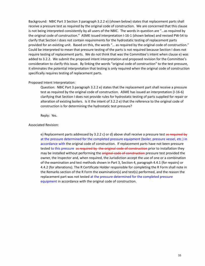
Background: NBIC Part 3 Section 3 paragraph 3.2.2 e) (shown below) states that replacement parts shall
receive a pressure test as required by the original code of construction. We are concerned that this clause
is not being interpreted consistently by all users of the NBIC. The words in question are “…as required by
the original code of construction.” ASME issued interpretation I-16-1 (shown below) and revised PW-54 to
clarify that Section I does not contain requirements for the hydrostatic testing of replacement parts
provided for an existing unit. Based on this, the words “… as required by the original code of construction.”
Could be interpreted to mean that pressure testing of the parts is not required because Section I does not
require testing of replacement parts. We do not think that was the Committee’s intent when clause e) was
added to 3.2.2. We submit the proposed intent interpretation and proposed revision for the Committee’s
consideration to clarify this issue. By linking the words “original code of construction” to the test pressure,
it eliminates the potential interpretation that testing is only required when the original code of construction
specifically requires testing of replacement parts.
Proposed Intent Interpretation:
Question: NBIC Part 3 paragraph 3.2.2 e) states that the replacement part shall receive a pressure
test as required by the original code of construction. ASME has issued an interpretation (I-16-6)
clarifying that Section I does not provide rules for hydrostatic testing of parts supplied for repair or
alteration of existing boilers. Is it the intent of 3.2.2 e) that the reference to the original code of
construction is for determining the hydrostatic test pressure?
Reply: Yes.
Associated Revision:
e) Replacement parts addressed by 3.2.2 c) or d) above shall receive a pressure test as required by
at the pressure determined for the completed pressure equipment (boiler, pressure vessel, etc.) in
accordance with the original code of construction. If replacement parts have not been pressure
tested to this pressure as required by the original code of construction prior to installation they
may be installed without performing the original code of construction pressure test provided the
owner, the Inspector and, when required, the Jurisdiction accept the use of one or a combination
of the examination and test methods shown in Part 3, Section 4, paragraph 4.4.1 (for repairs) or
4.4.2 (for alterations). The R Certificate Holder responsible for completing the R Form shall note in
the Remarks section of the R Form the examination(s) and test(s) performed, and the reason the
replacement part was not tested at the pressure determined for the completed pressure
equipment in accordance with the original code of construction.
33
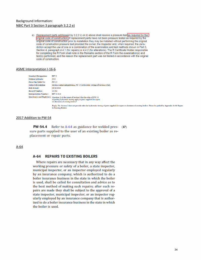
Background Information:
NBIC Part 3 Section 3 paragraph 3.2.2 e)
ASME Interpretation I-16-6
2017 Addition to PW-54
A-64
34

Item 19‐35: Interpretation Request for NBIC Part 3, 2.5.2 and 3.4 Submitted by: Jagadheesan Vellingiri Muthukumaraswamy [email protected]
Explanation of Need: Welds not repaired by R Stamp Holder and already existing on equipment if Post Weld Heat Treated, is not under the responsibility of the R Stamp Holder. Background Information: An R Certificate Holder is doing repair work on the shell side of heat exchanger, which was not PWHT earlier. As per client request, welded joints are Post Weld Heat Treated and considered an alteration; client wants shell side to undergo full Post Weld Heat Treatment including areas not repaired. NDE is being carried out for complete equipment and client wants PWHT for welds which are in services and without any repairs. Question 1: An R Certificate Holder is doing repair work on the shell side of heat exchanger, which was not Post Weld Heat Treated earlier. As per client request, repair welded joints are Post Weld Heat Treated and considered an alteration as per 3.4. For Welded Joints not repaired can Post Weld Heat Treatment be done and responsibility can be taken by R Certification and considered an alteration? Proposed Reply 1: No. Question 2: If R Stamp Holder holds WPS for the vessel with PWHT can that Post Weld Heat Treatment be carried out as per approved WPS in order to meet alteration requirement? Proposed Reply 2: Yes.
35

PROPOSED INTERPRETATION
Inquiry No.
19-36 Part 3, Section 3, 3.3.2 and 3.3.5, Routine Repairs of Section VIII Div.2 and Div.3 Pressure Vessels
Source
Inquirer: Narayanan Murugappan NBIC Committee PM: Jim Pillow
Subject
Part 3, Section 3, 3.3.2 Routine Repairs and 3.3.5 Repair of Section VIII Div.2 and Div.3 Pressure Vessels
Edition 2017
Question
Inquirer’s Proposed Q and R Question 1: Is Routine Repairs defined para 3.3.2 applicable to pressure vessels constructed to ASME Section VIII Division-2 and 3? Proposed Reply 1: Yes. Question 2: If the answer to the above question is Yes, are requirements specified in Para 3.3.5 to be followed for routine repairs to pressure vessels constructed to ASME Section VIII Division-2 and 3? Proposed Reply 2: Yes.
Reply
Committee’s Question
Q1; Is a repair plan required for all repairs of an ASME Section VIII Div. 2 or Div. 3 pressure vessel? Q2: May the repair plan for an ASME Section VIII Div.2 or Div.3 pressure vessel be accepted by the Inspector in lieu of the Authorized Inspection Agency or the Owner-User Inspection Organization? Q3: Must the Authorized Inspection Agency’s or the Owner-User Inspection Organization’s Inspector make an acceptance inspection of the repair of an ASME Section VIII Div.2 and Div.3 pressure vessels? Q4: Are routine repairs defined in Part 3, Section 3, 3.3.2, applicable to pressure vessels constructed to ASME Section VIII Div.2 or Div.3?
36
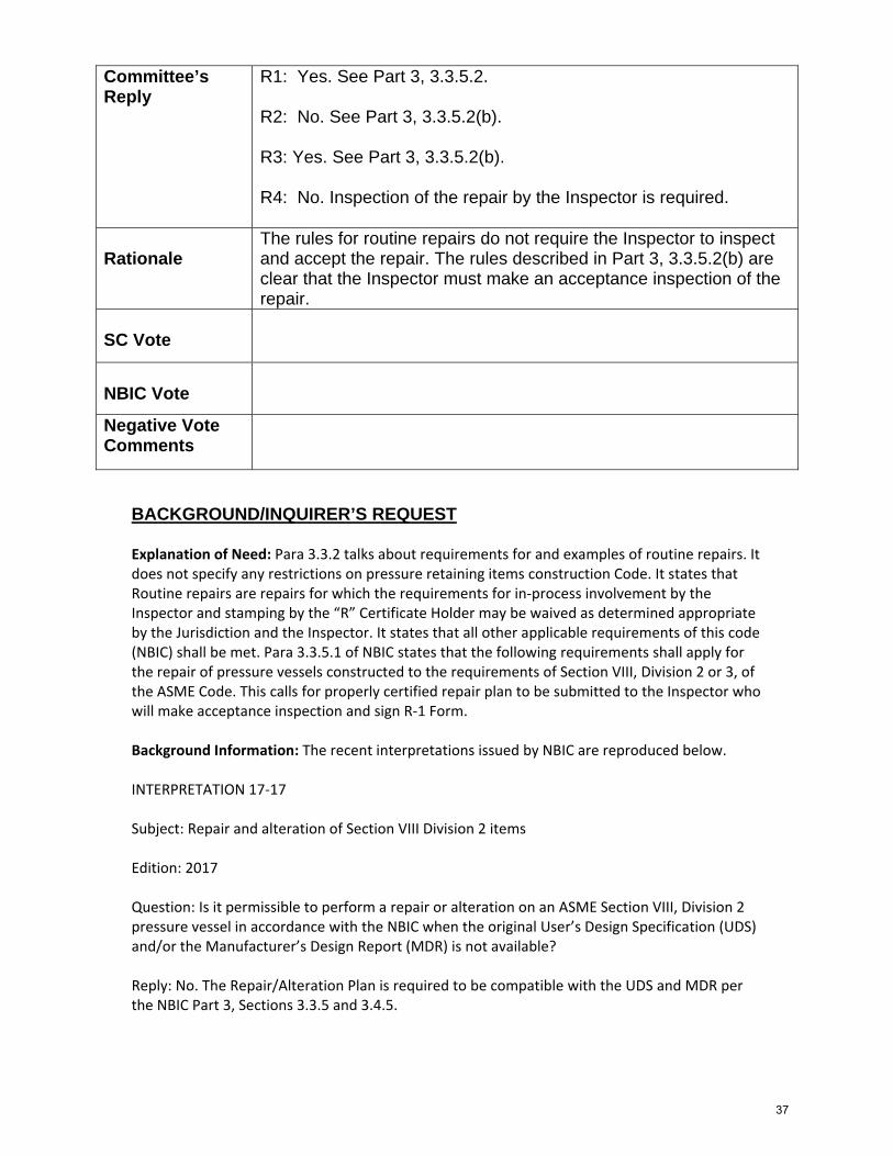
Committee’s Reply
R1: Yes. See Part 3, 3.3.5.2. R2: No. See Part 3, 3.3.5.2(b). R3: Yes. See Part 3, 3.3.5.2(b). R4: No. Inspection of the repair by the Inspector is required.
Rationale
The rules for routine repairs do not require the Inspector to inspect and accept the repair. The rules described in Part 3, 3.3.5.2(b) are clear that the Inspector must make an acceptance inspection of the repair.
SC Vote
NBIC Vote
Negative Vote Comments
BACKGROUND/INQUIRER’S REQUEST Explanation of Need: Para 3.3.2 talks about requirements for and examples of routine repairs. It does not specify any restrictions on pressure retaining items construction Code. It states that Routine repairs are repairs for which the requirements for in‐process involvement by the Inspector and stamping by the “R” Certificate Holder may be waived as determined appropriate by the Jurisdiction and the Inspector. It states that all other applicable requirements of this code (NBIC) shall be met. Para 3.3.5.1 of NBIC states that the following requirements shall apply for the repair of pressure vessels constructed to the requirements of Section VIII, Division 2 or 3, of the ASME Code. This calls for properly certified repair plan to be submitted to the Inspector who will make acceptance inspection and sign R‐1 Form. Background Information: The recent interpretations issued by NBIC are reproduced below. INTERPRETATION 17‐17 Subject: Repair and alteration of Section VIII Division 2 items Edition: 2017 Question: Is it permissible to perform a repair or alteration on an ASME Section VIII, Division 2 pressure vessel in accordance with the NBIC when the original User’s Design Specification (UDS) and/or the Manufacturer’s Design Report (MDR) is not available? Reply: No. The Repair/Alteration Plan is required to be compatible with the UDS and MDR per the NBIC Part 3, Sections 3.3.5 and 3.4.5.
37

INTERPRETATION 17‐08 Subject: Repair/Alteration Plans for ASME VIII, Division 2, Class 1 Pressure Vessels Edition: 2017 Question: Does the NBIC require a Repair/Alteration Plan for an ASME Section VIII, Division 2, Class 1 vessel to be certified by an engineer when a Manufacturer's Design Report was not required to be certified under the original code of construction? Reply: No.
NBIC EXCERPTS 3.3.5 REPAIR OF ASME SECTION VIII, DIVISION 2 OR 3, PRESSURE VESSELS 3.3.5.1 SCOPE The following requirements shall apply for the repair of pressure vessels constructed to the requirements of Section VIII, Division 2 or 3, of the ASME Code. 3.3.5.2 REPAIR PLAN The user shall prepare, or cause to have prepared, a detailed plan covering the scope of the repair. a) Engineer Review and Certification The repair plan shall be reviewed and certified by an engineer meeting the criteria of ASME Section VIII, Division 2 or 3, as applicable, for an engineer signing and certifying a Manufacturer’s Design Report. The review and certification shall be such as to ensure the work involved in the repair is compatible with the User’s Design Specification and the Manufacturer’s Design Report. Note: The engineer qualification criteria of the Jurisdiction where the pressure vessel is installed should be verified before selecting the certifying engineer. b) Authorized Inspection Agency Acceptance Following review and certification, the repair plan shall be submitted for acceptance to the Authorized Inspection Agency/Owner-User Inspection Organization whose Inspector will make the acceptance inspection and sign the Form R-1.
38
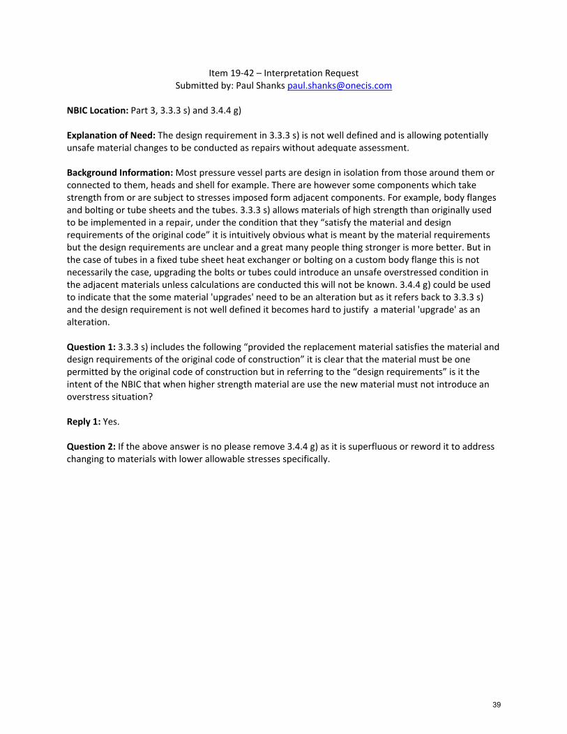
Item 19‐42 – Interpretation Request Submitted by: Paul Shanks [email protected]
NBIC Location: Part 3, 3.3.3 s) and 3.4.4 g) Explanation of Need: The design requirement in 3.3.3 s) is not well defined and is allowing potentially unsafe material changes to be conducted as repairs without adequate assessment. Background Information: Most pressure vessel parts are design in isolation from those around them or connected to them, heads and shell for example. There are however some components which take strength from or are subject to stresses imposed form adjacent components. For example, body flanges and bolting or tube sheets and the tubes. 3.3.3 s) allows materials of high strength than originally used to be implemented in a repair, under the condition that they “satisfy the material and design requirements of the original code” it is intuitively obvious what is meant by the material requirements but the design requirements are unclear and a great many people thing stronger is more better. But in the case of tubes in a fixed tube sheet heat exchanger or bolting on a custom body flange this is not necessarily the case, upgrading the bolts or tubes could introduce an unsafe overstressed condition in the adjacent materials unless calculations are conducted this will not be known. 3.4.4 g) could be used to indicate that the some material 'upgrades' need to be an alteration but as it refers back to 3.3.3 s) and the design requirement is not well defined it becomes hard to justify a material 'upgrade' as an alteration. Question 1: 3.3.3 s) includes the following “provided the replacement material satisfies the material and design requirements of the original code of construction” it is clear that the material must be one permitted by the original code of construction but in referring to the “design requirements” is it the intent of the NBIC that when higher strength material are use the new material must not introduce an overstress situation? Reply 1: Yes. Question 2: If the above answer is no please remove 3.4.4 g) as it is superfluous or reword it to address changing to materials with lower allowable stresses specifically.
39

Item 19‐44: Intent Interpretation Request for Part 3, 1.6.6.2, 1.6.7.2, & 1.6.8.2 Submitted by: Laura Fuhrmann [email protected]
Explanation of Need: Many, if not all calibration labs are already accredited to ISO/IEC 17025:2017 and will be required to by 2020. No lab will bother accreditation to 2005 after that, so finding a calibration house will be difficult. Background: NBIC Part 3, 1.6.6.2 M‐5‐A, 1.6.7.2 M‐1, 1.6.7.2 M‐4‐A, 1.6.7.2 M‐5‐A, 1.6.8.2 M‐1, 1.6.8.2 M‐4‐A, and 1.6.8.2 M‐5‐A Question: The listed paragraphs show service to be provided in accordance with ISO/IEC 17025:2005. The 17025 standard has been revised to the 2017 version, and all labs accredited as such have a 3 year transition window. Reply: A change similar to ASME section III, which does not list a specific revision, instead, wording it as "most current".
40

Item NB15‐1405 (formally IN14‐0401)
The following is a history of record number NB15‐1405, formally inquiry record 14‐0401, found
in NBIC committee Minutes from inception in 2014.
January 2014 (see attachment “A”)
Main Committee Minutes:IN14-0401 - Part 3, 1.2 - Question 1: The NBIC Part 3 paragraph 1.2 states that a repair shall be carried out “insofar as possible to the section and edition of the ASME code most applicable to the work planned.” If a vessel is constructed using SA-517-E (P-11B) material to ASME Section VIII Div. 1, where production and weld procedure impact tests were required during construction, would a repair to a crack in the shell require production and weld procedure impact testing under the NBIC? Proposed Reply 1: Yes. (No attachment) Question 2: If the answer to Question 1 is yes and there was no SA-517-E material from the original lot available, would the repair require the addition of new base material (e.g. a flush patch around the area of the crack) so that production impact tests could be performed with the original base metal to the new base metal? Proposed Reply 1: Yes. Question 3: If the vessel described in Question 1 was to be altered by adding an SA-675 (P-1) pump flange to the shell, would production and weld procedure impact tests be required using the same lot P-1 and P-11B base materials as used in the alteration? Proposed Reply 1: Yes. January 2014 A task group of Walt Sperko, Bob Wielgoszinski (PM), and George Galanes will work on this inquiry.
SC RA Minutes: January 2014 Bob Wielgoszinski presented a document request for interpretation associated with welded repairs to UHT vessels. A task group of Walt Sperko, Bob Wielgoszinski (PM), and George Galanes will work on this inquiry.
SG RA Specific Minutes: January 2014 Bob Wielgoszinski presented a document request for interpretation associated with welded repairs to UHT vessels. A task group of Walt Sperko, Bob Wielgoszinski (PM), and George Galanes will work on this inquiry.
January 2015 (see attachment “B”)
Main Committee MinutesItem Number: IN14-0401 NBIC Location: Part 3, 1.2 Attachment Pages 72-73 General Description: Interpretation questions regarding requirements for production impact tests after repair or alteration of a vessel Subgroup: Repairs and Altterations Task Group: Unknown Meeting Action: Mr. Galanes gave a report. The Subcommittee on Repairs and Alterations voted unanimously close this interpretation with no response. The Subcommittee on Repairs and Alterations opened a new action item NB15-1405 to
41

address production impact tests. Mr. Wielgoszinski explained the subject of the interpretation and the new action item. The NBIC Committee voted unanimously to close this interpretation with no response.
SC RA Minutes: January 2015 Mr. Wielgoszinski provided a report. After consideration, Mr. Wielgoszinski decided to withdraw the inquiry and requested a new item to address impact testing of P11B material. A motion was made to close this interpretation and open up an action Item. The new action item will be: NB15-1405 Part 3-Impact testing of P-11B Material, SC R and A (From IN14-0401) A task group was formed with Bob Wielgoszinski, as project manager and member Ben Schaefer, Walt Sperko, Monty Bost, and Dave Ford. (Attachment Pages 8-9)
July 2015
No report. Not included on MC or RA agendas.
January 2016
No minutes available.
July 2016
No report. Not included on MC or RA agendas.
January 2017
No report. Not included on MC or RA agendas.
July 2017
No report. Not included on MC or RA agendas.
January 2018
No report. Not included on MC or RA agendas.
42

P a g e | 1 1/9/14
IN14‐0401
Request for Interpretation Robert V. Wielgoszinski
Hartford Steam Boiler of CT
Item IN 14‐0401
Purpose Code Interpretation & possible revision to present Code rules
Scope: Repairs and alterations to vessels constructed of ferritic materials with tensile properties enhanced by heat treatment, i.e. Part UHT material.
Background During the construction of liquid propane vessels it is typical to use SA‐517 Gr. E (P‐ No. 11B) for use as heads and shells for propane transport tanks. The ASME Code requires the base materials, welding materials, and the WPS’s to be qualified with impact tests. Also, the Code requires production impact testing to be performed. This is where the actual vessel material, actual filler materials, are welded with the actual WPS to be used in production, and the weld coupon is impact tested to meet the specified results of Section VIII. To do so, the Manufacturer of the vessel is sure to purchase enough extra base and filler material to perform these tests. When repairs / alterations are made to these vessels the NBIC requires the rules of the original construction Code to be followed. As such, any new material to be added to a vessel or any WPS’s used or any filler metal used for the repair must then be impact tested and meet the results stated in Section VIII. Also, production impacts must therefore be made since this is a mandatory Section VIII requirement. This is usually accomplished by making a weld coupon out of existing material cut from the vessel and welding it to the new material to be added to the vessel, and then impact testing specimens from that coupon. But, not all repairs / alterations lend themselves the ability to take existing material from the vessel. If a small nozzle is added to the vessel, only a few inches of material is taken from the vessel. Or say a crack is to be weld repaired or there is weld metal build up to be made on some worn or wasted area. Then there is no extra material to be taken away from the vessel to run coupons for production impacts. Strict interpretation of the ASME Code would now require a piece of steel to be removed to run production impacts and then a flush patch installed over the area removed. Some individuals look at the words in NBIC, Part 3, Section 1, paragraph 1.2, where it says, “…the standard governing the original construction shall conform, insofar as possible…” gives one the leeway to not require production impacts because it’s not possible. Others indicated that it is possible but not practical to cut perfectly good material out of a vessel when there is no need to. And others will say that the ASME clearly requires existing material to be removed to run impact tests. One thing is clear though, and that is there is lack of uniformity in applying these rules. So we are looking to the NBIC to provide some guidance in this matter. The Jurisdiction in this case is the US DOT, and 49CFR Chapter 1 § 180.413(a)(1) states that the NBIC is to be followed for repairs and modifications. DOT is also looking to the NBIC for clarification.
43
P a g e | 2 1/9/14
IN14‐0401
Depending on the responses to the inquiry it may be prudent revise the Code to be more specific in this area of UHT materials.
Proposed Questions
Question 1: The NBIC Part 3 paragraph 1.2 states that a repair shall be carried out “insofar as possible to the section and edition of the ASME code most applicable to the work planned.” If a vessel is constructed using SA‐517‐E (P‐11B) material to ASME Section VIII Div. 1, where production and weld procedure impact tests were required during construction, would a repair to a crack in the shell require production and weld procedure impact testing under the NBIC? Proposed Reply 1: Yes. Question 2: If the answer to Question 1 is yes and there was no SA‐517‐E material from the original lot available, would the repair require the addition of new base material (e.g. a flush patch around the area of the crack) so that production impact tests could be performed with the original base metal to the new base metal? Proposed Reply 1: Yes. Question 3: If the vessel described in Question 1 was to be altered by adding an SA‐675 (P‐1) pump flange to the shell, would production and weld procedure impact tests be required using the same lot P‐1 and P‐11B base materials as used in the alteration? Proposed Reply 1: Yes.
44

45

46

Item NB16‐1402 (NBIC Part 3, Section 6)
Supplement 14 Life Extension of High Pressure Fiber Reinforced Plastic Pressure Vessels
S14.1 Scope This document may be used to evaluate whether the service life of high pressure fiber reinforced plastic pressure vessels (FRP) can be extended for an additional lifetime. High pressure means vessels with a working pressure from 3,000 psi (20 MPa) to 15,000 psi (103 MPa). For vessels intended for cyclic service, fatigue testing of new vessels is carried out by the vessel manufacturer to be certain that the vessel will not fail in service and such testing is typically required by regulatory authorities. Fatigue design and testing is the starting point for consideration of life extension.
S14.2 General
a) The procedure for in‐service testing of high pressure composite pressure vessels, Supplement 10 herein, is incorporated by reference into this procedure for life extension of high pressure composite pressure vessels. Supplement 10 is based on acoustic emission (AE) testing, specifically modal AE (MAE) testing. The MAE inspection procedure employs detection and analysis techniques similar to those found in seismology and SONAR. Much as with earthquakes, transient acoustical impulses arise in a composite material due to the motion of sources such as the rupture of fibers. These transients propagate as waves through the material and, if properly measured and analyzed by the methods in Supplement 10, the captured waves reveal, for example, how many fibers have ruptured. Similar information about other sources is also determinable, such as the presence and size of delaminations. Delaminations can play a significant role in vessel fatigue life, particularly delaminations near the transition regions and in the heads. The rupture behavior can be used to determine the integrity of the vessel. However, the development of criteria for life extension (LE) requires an understanding of the vessel design and fatigue life.
b) Fatigue testing of out of life vessels is a crucial part of the life extension process. It is used to validate the mechanical behavior of the vessels and to develop the numerical values for the allowables in the MAE pass/fail criteria for the particular design, material and construction.
S 14.3 Life Extension Procedure
a) New vessel fatigue life testing data shall be obtained from the Manufacturer’s Design Report (MDR) and the number of cycles in a lifetime shall be determined from the MDR. The type of vessel under consideration for life extension shall have been shown through testing to be capable of sustaining at least three lifetimes of cycles to developed fill pressure followed by a subsequent burst test at a pressure greater than minimum design burst pressure.
b) An evaluation of the service the vessel has seen should take into account any operational
conditions that may have differed from those used in the design testing and analysis. Such conditions include for example exposure to more severe weather than expected, more cycles
47
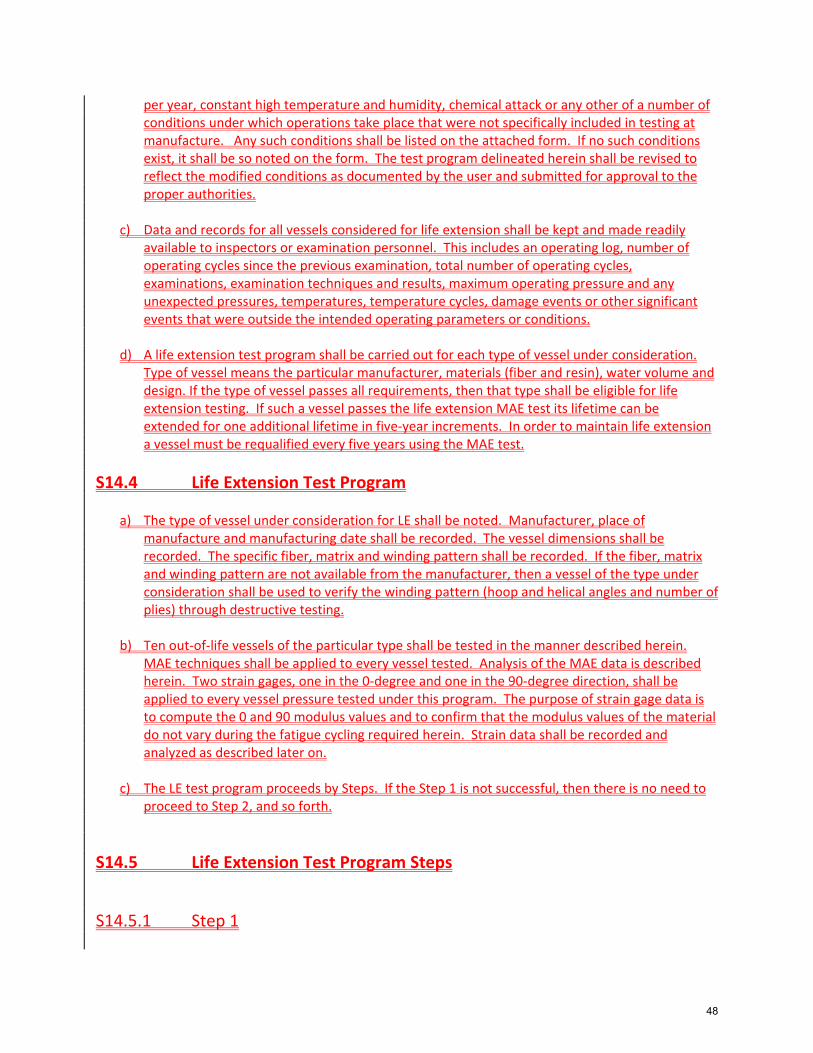
per year, constant high temperature and humidity, chemical attack or any other of a number of conditions under which operations take place that were not specifically included in testing at manufacture. Any such conditions shall be listed on the attached form. If no such conditions exist, it shall be so noted on the form. The test program delineated herein shall be revised to reflect the modified conditions as documented by the user and submitted for approval to the proper authorities.
c) Data and records for all vessels considered for life extension shall be kept and made readily
available to inspectors or examination personnel. This includes an operating log, number of operating cycles since the previous examination, total number of operating cycles, examinations, examination techniques and results, maximum operating pressure and any unexpected pressures, temperatures, temperature cycles, damage events or other significant events that were outside the intended operating parameters or conditions.
d) A life extension test program shall be carried out for each type of vessel under consideration. Type of vessel means the particular manufacturer, materials (fiber and resin), water volume and design. If the type of vessel passes all requirements, then that type shall be eligible for life extension testing. If such a vessel passes the life extension MAE test its lifetime can be extended for one additional lifetime in five‐year increments. In order to maintain life extension a vessel must be requalified every five years using the MAE test.
S14.4 Life Extension Test Program
a) The type of vessel under consideration for LE shall be noted. Manufacturer, place of manufacture and manufacturing date shall be recorded. The vessel dimensions shall be recorded. The specific fiber, matrix and winding pattern shall be recorded. If the fiber, matrix and winding pattern are not available from the manufacturer, then a vessel of the type under consideration shall be used to verify the winding pattern (hoop and helical angles and number of plies) through destructive testing.
b) Ten out‐of‐life vessels of the particular type shall be tested in the manner described herein.
MAE techniques shall be applied to every vessel tested. Analysis of the MAE data is described herein. Two strain gages, one in the 0‐degree and one in the 90‐degree direction, shall be applied to every vessel pressure tested under this program. The purpose of strain gage data is to compute the 0 and 90 modulus values and to confirm that the modulus values of the material do not vary during the fatigue cycling required herein. Strain data shall be recorded and analyzed as described later on.
c) The LE test program proceeds by Steps. If the Step 1 is not successful, then there is no need to
proceed to Step 2, and so forth.
S14.5 Life Extension Test Program Steps
S14.5.1 Step 1
48
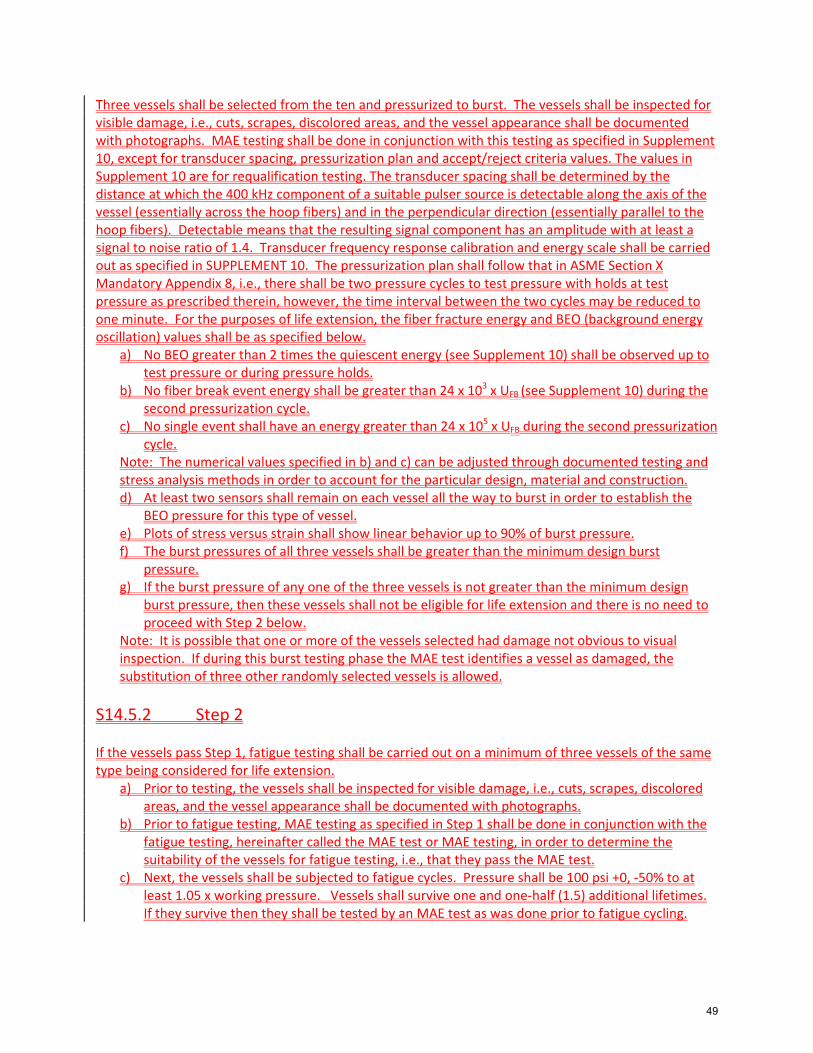
Three vessels shall be selected from the ten and pressurized to burst. The vessels shall be inspected for visible damage, i.e., cuts, scrapes, discolored areas, and the vessel appearance shall be documented with photographs. MAE testing shall be done in conjunction with this testing as specified in Supplement 10, except for transducer spacing, pressurization plan and accept/reject criteria values. The values in Supplement 10 are for requalification testing. The transducer spacing shall be determined by the distance at which the 400 kHz component of a suitable pulser source is detectable along the axis of the vessel (essentially across the hoop fibers) and in the perpendicular direction (essentially parallel to the hoop fibers). Detectable means that the resulting signal component has an amplitude with at least a signal to noise ratio of 1.4. Transducer frequency response calibration and energy scale shall be carried out as specified in SUPPLEMENT 10. The pressurization plan shall follow that in ASME Section X Mandatory Appendix 8, i.e., there shall be two pressure cycles to test pressure with holds at test pressure as prescribed therein, however, the time interval between the two cycles may be reduced to one minute. For the purposes of life extension, the fiber fracture energy and BEO (background energy oscillation) values shall be as specified below.
a) No BEO greater than 2 times the quiescent energy (see Supplement 10) shall be observed up to test pressure or during pressure holds.
b) No fiber break event energy shall be greater than 24 x 103 x UFB (see Supplement 10) during the second pressurization cycle.
c) No single event shall have an energy greater than 24 x 105 x UFB during the second pressurization cycle.
Note: The numerical values specified in b) and c) can be adjusted through documented testing and stress analysis methods in order to account for the particular design, material and construction. d) At least two sensors shall remain on each vessel all the way to burst in order to establish the
BEO pressure for this type of vessel. e) Plots of stress versus strain shall show linear behavior up to 90% of burst pressure. f) The burst pressures of all three vessels shall be greater than the minimum design burst
pressure. g) If the burst pressure of any one of the three vessels is not greater than the minimum design
burst pressure, then these vessels shall not be eligible for life extension and there is no need to proceed with Step 2 below.
Note: It is possible that one or more of the vessels selected had damage not obvious to visual inspection. If during this burst testing phase the MAE test identifies a vessel as damaged, the substitution of three other randomly selected vessels is allowed.
S14.5.2 Step 2 If the vessels pass Step 1, fatigue testing shall be carried out on a minimum of three vessels of the same type being considered for life extension.
a) Prior to testing, the vessels shall be inspected for visible damage, i.e., cuts, scrapes, discolored areas, and the vessel appearance shall be documented with photographs.
b) Prior to fatigue testing, MAE testing as specified in Step 1 shall be done in conjunction with the fatigue testing, hereinafter called the MAE test or MAE testing, in order to determine the suitability of the vessels for fatigue testing, i.e., that they pass the MAE test.
c) Next, the vessels shall be subjected to fatigue cycles. Pressure shall be 100 psi +0, ‐50% to at least 1.05 x working pressure. Vessels shall survive one and one‐half (1.5) additional lifetimes. If they survive then they shall be tested by an MAE test as was done prior to fatigue cycling.
49
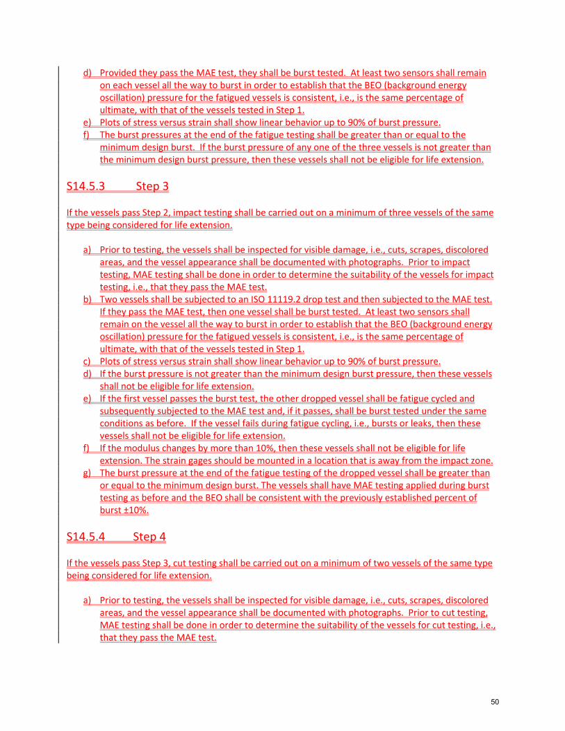
d) Provided they pass the MAE test, they shall be burst tested. At least two sensors shall remain on each vessel all the way to burst in order to establish that the BEO (background energy oscillation) pressure for the fatigued vessels is consistent, i.e., is the same percentage of ultimate, with that of the vessels tested in Step 1.
e) Plots of stress versus strain shall show linear behavior up to 90% of burst pressure. f) The burst pressures at the end of the fatigue testing shall be greater than or equal to the
minimum design burst. If the burst pressure of any one of the three vessels is not greater than the minimum design burst pressure, then these vessels shall not be eligible for life extension.
S14.5.3 Step 3 If the vessels pass Step 2, impact testing shall be carried out on a minimum of three vessels of the same type being considered for life extension.
a) Prior to testing, the vessels shall be inspected for visible damage, i.e., cuts, scrapes, discolored areas, and the vessel appearance shall be documented with photographs. Prior to impact testing, MAE testing shall be done in order to determine the suitability of the vessels for impact testing, i.e., that they pass the MAE test.
b) Two vessels shall be subjected to an ISO 11119.2 drop test and then subjected to the MAE test. If they pass the MAE test, then one vessel shall be burst tested. At least two sensors shall remain on the vessel all the way to burst in order to establish that the BEO (background energy oscillation) pressure for the fatigued vessels is consistent, i.e., is the same percentage of ultimate, with that of the vessels tested in Step 1.
c) Plots of stress versus strain shall show linear behavior up to 90% of burst pressure. d) If the burst pressure is not greater than the minimum design burst pressure, then these vessels
shall not be eligible for life extension. e) If the first vessel passes the burst test, the other dropped vessel shall be fatigue cycled and
subsequently subjected to the MAE test and, if it passes, shall be burst tested under the same conditions as before. If the vessel fails during fatigue cycling, i.e., bursts or leaks, then these vessels shall not be eligible for life extension.
f) If the modulus changes by more than 10%, then these vessels shall not be eligible for life extension. The strain gages should be mounted in a location that is away from the impact zone.
g) The burst pressure at the end of the fatigue testing of the dropped vessel shall be greater than or equal to the minimum design burst. The vessels shall have MAE testing applied during burst testing as before and the BEO shall be consistent with the previously established percent of burst ±10%.
S14.5.4 Step 4 If the vessels pass Step 3, cut testing shall be carried out on a minimum of two vessels of the same type being considered for life extension.
a) Prior to testing, the vessels shall be inspected for visible damage, i.e., cuts, scrapes, discolored areas, and the vessel appearance shall be documented with photographs. Prior to cut testing, MAE testing shall be done in order to determine the suitability of the vessels for cut testing, i.e., that they pass the MAE test.
50
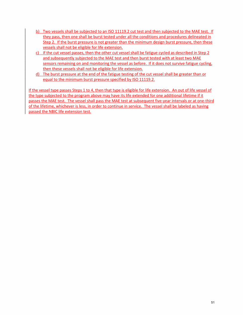
b) Two vessels shall be subjected to an ISO 11119.2 cut test and then subjected to the MAE test. If they pass, then one shall be burst tested under all the conditions and procedures delineated in Step 2. If the burst pressure is not greater than the minimum design burst pressure, then these vessels shall not be eligible for life extension.
c) If the cut vessel passes, then the other cut vessel shall be fatigue cycled as described in Step 2 and subsequently subjected to the MAE test and then burst tested with at least two MAE sensors remaining on and monitoring the vessel as before. If it does not survive fatigue cycling, then these vessels shall not be eligible for life extension.
d) The burst pressure at the end of the fatigue testing of the cut vessel shall be greater than or equal to the minimum burst pressure specified by ISO 11119.2.
If the vessel type passes Steps 1 to 4, then that type is eligible for life extension. An out of life vessel of the type subjected to the program above may have its life extended for one additional lifetime if it passes the MAE test. The vessel shall pass the MAE test at subsequent five‐year intervals or at one‐third of the lifetime, whichever is less, in order to continue in service. The vessel shall be labeled as having passed the NBIC life extension test.
51
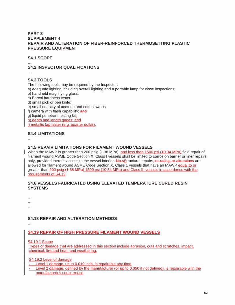
SUPPL. 4
PART 3 SUPPLEMENT 4 REPAIR AND ALTERATION OF FIBER-REINFORCED THERMOSETTING PLASTIC PRESSURE EQUIPMENT S4.1 SCOPE … S4.2 INSPECTOR QUALIFICATIONS … UPPL. 4
S4.3 TOOLS The following tools may be required by the Inspector: a) adequate lighting including overall lighting and a portable lamp for close inspections; b) handheld magnifying glass; c) Barcol hardness tester; d) small pick or pen knife; e) small quantity of acetone and cotton swabs; f) camera with flash capability; and g) liquid penetrant testing kit; h) depth and length gages; and i) metallic tap tester (e.g. quarter dollar). S4.4 LIMITATIONS … S4.5 REPAIR LIMITATIONS FOR FILAMENT WOUND VESSELS When the MAWP is greater than 200 psig (1.38 MPa), and less than 1500 psi (10.34 MPa) field repair of filament wound ASME Code Section X, Class I vessels shall be limited to corrosion barrier or liner repairs only, provided there is access to the vessel interior. No sStructural repairs, re-rating, or alterations are allowed for filament wound ASME Code Section X, Class 1 vessels that have an MAWP equal to or greater than 200 psig (1.38 MPa) 1500 psi (10.34 MPa) and Class III vessels in accordance with the requirements of S4.19. S4.6 VESSELS FABRICATED USING ELEVATED TEMPERATURE CURED RESIN SYSTEMS … … … SUPPL. 4
S4.18 REPAIR AND ALTERATION METHODS … S4.19 REPAIR OF HIGH PRESSURE FILAMENT WOUND VESSELS S4.19.1 Scope Types of damage that are addressed in this section include abrasion, cuts and scratches, impact, chemical, fire and heat, and weathering. S4.19.2 Level of damage - Level 1 damage, up to 0.010 inch, is repairable any time - Level 2 damage, defined by the manufacturer (or up to 0.050 if not defined), is repairable with the
manufacturer’s concurrence
52
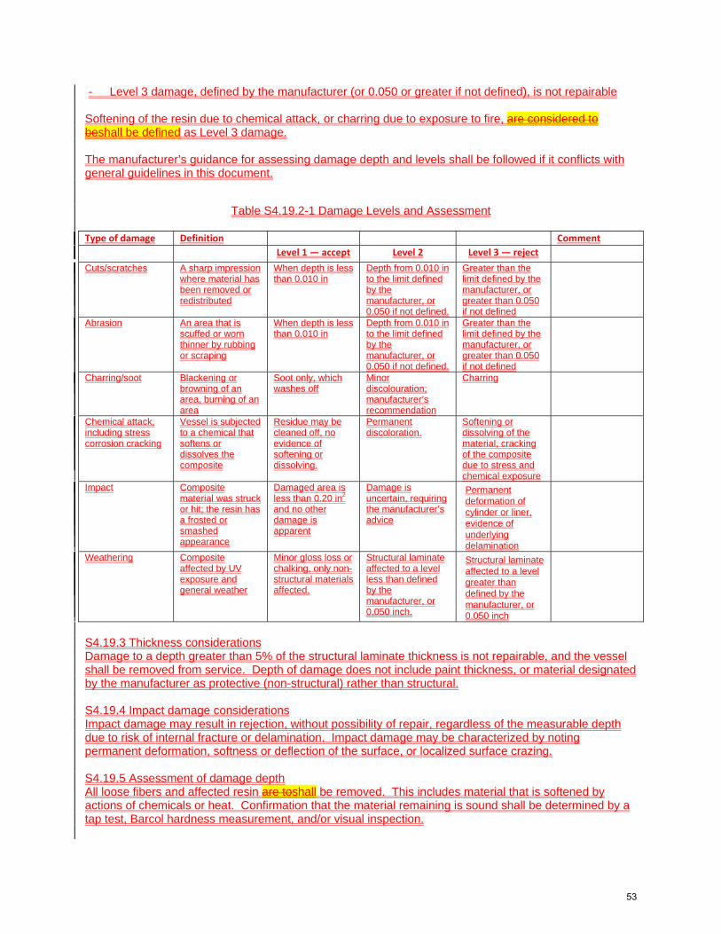
- Level 3 damage, defined by the manufacturer (or 0.050 or greater if not defined), is not repairable Softening of the resin due to chemical attack, or charring due to exposure to fire, are considered to beshall be defined as Level 3 damage. The manufacturer’s guidance for assessing damage depth and levels shall be followed if it conflicts with general guidelines in this document.
Table S4.19.2-1 Damage Levels and Assessment
Type of damage Definition Comment
Level 1 — accept Level 2 Level 3 — reject Cuts/scratches A sharp impression
where material has been removed or redistributed
When depth is less than 0.010 in
Depth from 0.010 in to the limit defined by the manufacturer, or 0.050 if not defined.
Greater than the limit defined by the manufacturer, or greater than 0.050 if not defined
Abrasion An area that is scuffed or worn thinner by rubbing or scraping
When depth is less than 0.010 in
Depth from 0.010 in to the limit defined by the manufacturer, or 0.050 if not defined.
Greater than the limit defined by the manufacturer, or greater than 0.050 if not defined
Charring/soot Blackening or browning of an area, burning of an area
Soot only, which washes off
Minor discolouration; manufacturer’s recommendation
Charring
Chemical attack, including stress corrosion cracking
Vessel is subjected to a chemical that softens or dissolves the composite
Residue may be cleaned off, no evidence of softening or dissolving.
Permanent discoloration.
Softening or dissolving of the material, cracking of the composite due to stress and chemical exposure
Impact Composite material was struck or hit; the resin has a frosted or smashed appearance
Damaged area is less than 0.20 in2
and no other damage is apparent
Damage is uncertain, requiring the manufacturer’s advice
Permanent deformation of cylinder or liner, evidence of underlying delamination
Weathering Composite affected by UV exposure and general weather
Minor gloss loss or chalking, only non-structural materials affected.
Structural laminate affected to a level less than defined by the manufacturer, or 0.050 inch.
Structural laminate affected to a level greater than defined by the manufacturer, or 0.050 inch
S4.19.3 Thickness considerations Damage to a depth greater than 5% of the structural laminate thickness is not repairable, and the vessel shall be removed from service. Depth of damage does not include paint thickness, or material designated by the manufacturer as protective (non-structural) rather than structural. S4.19.4 Impact damage considerations Impact damage may result in rejection, without possibility of repair, regardless of the measurable depth due to risk of internal fracture or delamination. Impact damage may be characterized by noting permanent deformation, softness or deflection of the surface, or localized surface crazing. S4.19.5 Assessment of damage depth All loose fibers and affected resin are toshall be removed. This includes material that is softened by actions of chemicals or heat. Confirmation that the material remaining is sound shall be determined by a tap test, Barcol hardness measurement, and/or visual inspection.
53

S4.19.6 Repair procedure a) Non-structural material, including paint, shall be removed from any area involved in the repair. b) Resin used in structural repairs shall be compatible with the resin used to fabricate the vessel. c) Cloth patches made of glass or carbon fiber may be used in the repair and to cover the repaired
area. 1) Cloth patches shall extend at least 0.5 inches beyond the edge of the repair area, and
subsequent layers mustshall extend at least 0.25 inch beyond the edge of the previous patch.
2) Total patch thickness shall not be more than 5% of the structural thickness of the original laminate.
d) A layer of fiber wound continuously in the hoop direction may be applied over the repair. e) Non-structural material may be applied to the repaired area for protection if originally used in the
vessel design. f) The repaired area may be covered with epoxy, polyurethane, or other compatible paint. g) The repaired area shall be cured at a temperature that will not degrade the resin in the vessel. It
may be cured prior to applying any non-structural material or paint. h) The repair shall be confirmed by either:
1) A tap test or Barcol hardness measurement conducted on the structural material after cure and prior to applying any non-structural material or paint, or
2) A Modal Acoustic Emission test, in accordance with Part 2 S10.10, conducted after cure of the structural material
i) A hydrostatic proof test shall be conducted following confirmation of the repair. S4.19.7 Acceptance of the vessel for return to service The repair shall meet the repair confirmation requirement (i.e. confirmation of soundness using the tap test or Barcol hardness measurement, or confirmation using MAE). There shall be no delamination of the repaired area resulting from thea hydrostatic proof test in accordance with the Design Specification. A vessel that does not meet the requirements of the repair confirmation or hydrostatic proof test shall not be returned to service.
54
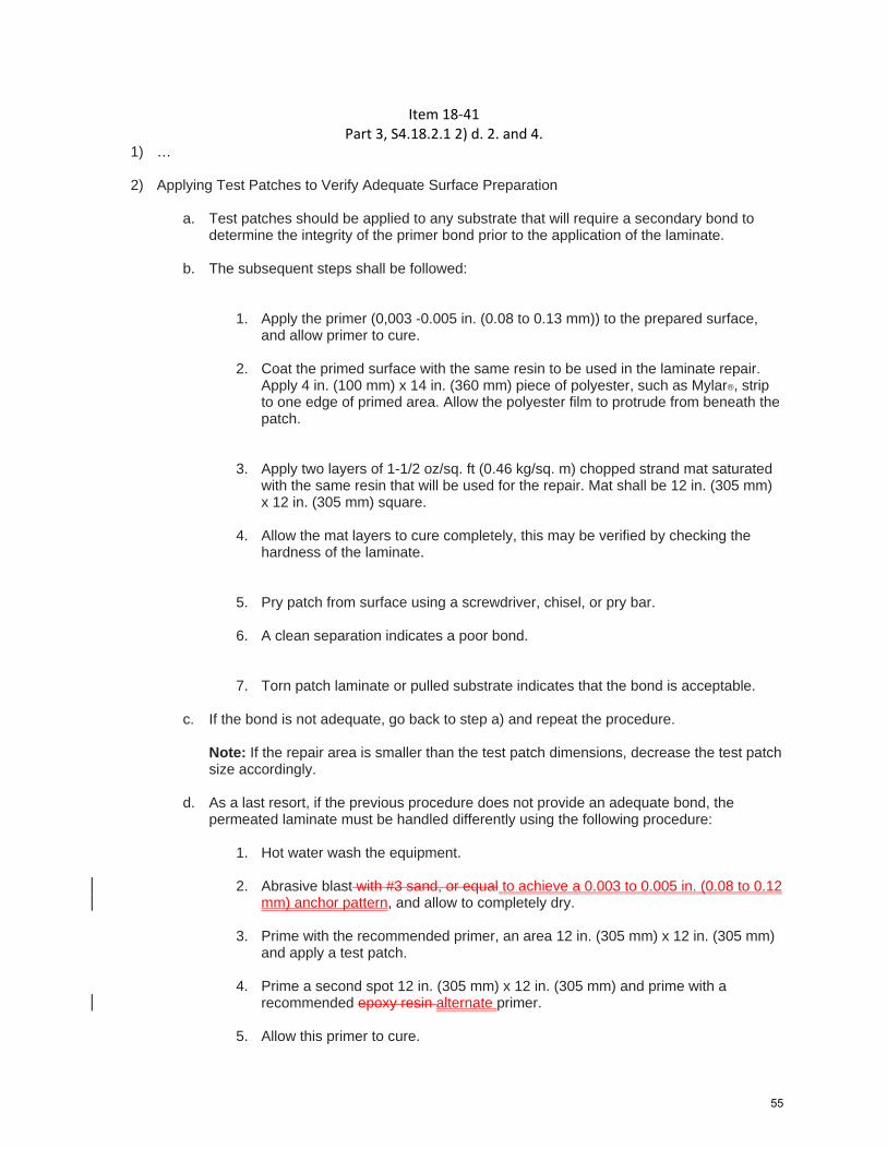
Item 18‐41 Part 3, S4.18.2.1 2) d. 2. and 4.
1) …
2) Applying Test Patches to Verify Adequate Surface Preparation
a. Test patches should be applied to any substrate that will require a secondary bond to determine the integrity of the primer bond prior to the application of the laminate.
b. The subsequent steps shall be followed:
1. Apply the primer (0,003 -0.005 in. (0.08 to 0.13 mm)) to the prepared surface,
and allow primer to cure.
2. Coat the primed surface with the same resin to be used in the laminate repair. Apply 4 in. (100 mm) x 14 in. (360 mm) piece of polyester, such as Mylar®, strip to one edge of primed area. Allow the polyester film to protrude from beneath the patch.
3. Apply two layers of 1-1/2 oz/sq. ft (0.46 kg/sq. m) chopped strand mat saturated with the same resin that will be used for the repair. Mat shall be 12 in. (305 mm) x 12 in. (305 mm) square.
4. Allow the mat layers to cure completely, this may be verified by checking the hardness of the laminate.
5. Pry patch from surface using a screwdriver, chisel, or pry bar.
6. A clean separation indicates a poor bond.
7. Torn patch laminate or pulled substrate indicates that the bond is acceptable.
c. If the bond is not adequate, go back to step a) and repeat the procedure.
Note: If the repair area is smaller than the test patch dimensions, decrease the test patch size accordingly.
d. As a last resort, if the previous procedure does not provide an adequate bond, the permeated laminate must be handled differently using the following procedure:
1. Hot water wash the equipment.
2. Abrasive blast with #3 sand, or equal to achieve a 0.003 to 0.005 in. (0.08 to 0.12 mm) anchor pattern, and allow to completely dry.
3. Prime with the recommended primer, an area 12 in. (305 mm) x 12 in. (305 mm)
and apply a test patch.
4. Prime a second spot 12 in. (305 mm) x 12 in. (305 mm) and prime with a recommended epoxy resin alternate primer.
5. Allow this primer to cure.
55

Part 3, S4.18.2.2 2)
1) …
2) Note that any cracks, delaminations, or permeated surfaces must be removed. If the damage is
deeper than the corrosion barrier and the material removed reaches the structural laminate, the vessel is not repairable. An adequate size abrasive or proper sanding disc must be used to obtain a 0.003 to 0.005 0.002 to 0.003 in (0.05 to 0.08 mm) anchor pattern to the area that requires the repair.
3) Preparation of any surface requires that basic rules, common to all substrates, be followed. These rules are as outlined below:
a. Surface must be free of contaminants;
b. Surface must be structurally sound;
c. Surface must have adequate anchor pattern;
d. Surface must be dry;
e. Surface must be primed with recommended primer. Note: After the surface has been properly prepared, it must be kept clean and dry until laminating can be started. Dust, moisture, or traces of oil that come in contact with the surface may act as a mold release or act to inhibit the cure and prevent a good secondary bond. Laminating should be done within two hours of the surface preparation.
56

Record 17-166 S3.3 REPAIRS OF A ROUTINE NATURE a) The following repairs shall be considered routine, and shall comply with NBIC Part 3, 3.3.2.
1) Machining — routine repair shall not include the machining of pressure-retaining parts with the exception of minor machining for cleaning and joint preparation not to exceed 1/32 in. (0.8 mm) of material thickness. 2) Repair of Gasket Surfaces — re-machining of gasket surfaces, re-serrating, or flattening is permitted if the design thickness is maintained. 3) Replacing Individual Tubes — drilling out and replacing tubes with new tubes or repaired tubes. Only certified materials shall be used for this repair. 4) Nozzle Replacement — replacement of nozzles by removing the old nozzle and cementing a new nozzle in place. This is applicable for nozzles with inside diameters not exceeding 18 in. (460 mm). 6 inches (152 mm).
4) 6) Surface Repair — surface repair by installation of plugs or inlay material shall not exceed 1 in.3 (16 cm3) of total volume.
5) 7) Replacement or Addition of Non-Load Bearing Attachments to Pressure-Retaining Item — For attachment of non-load bearing attachments to pressure-retaining items, the cementing procedure specification need only be qualified for the pressure part and cement to be used.
b) Complete records of these routine repairs shall be kept for review by the Inspector. The records shall include the number of tubes replaced or plugged and their location within the tube bundle.
57

NBIC Subcommittee R&A Action Block
Subject Code Revision to Part 3, 2.5.3.6
File Number NB18-12 Prop. on Pg. 2
Proposed Revision
1
Statement of Need
The revision is to Welding Method 6 to allow for weld build-up limited to 100 square inches on only Grade 91 tube OD surfaces for local erosion or mechanical damage.
Project Manager
John Siefert/G. Galanes
SubGroup Negatives
SG Meeting Date
Background; Welding Method 6 was successfully introduced into the NBIC, part 3 to permit butt weld repair with no PWHT. This action permits weld build-up of the Grade 91 tubes within the boiler setting and same limitations to repair erosion or mechanical damage without the need for complete tube replacement. To ensure adequate controls, the size of the repair are using a weld overlay is limited to 100 square inches. The size limitation for the weld build-up repair of 100 square inches is predicated on similar language which appears in Part 3 Supplements 2 and 4. For weld build-up repairs, section 2.5.3.6 c) 5) f) does not limit the F-No. 43 filler materials because the need for the weld build-up may be due to corrosion or erosion. In these examples, it may be necessary to use an optimized filler material which is otherwise prohibited in section 2.5.3.6 c) 5) d) for full thickness repairs.
58
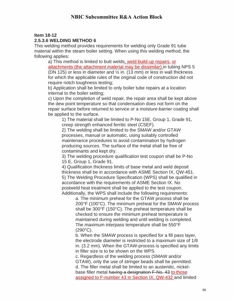
NBIC Subcommittee R&A Action Block
Item 18-12 2.5.3.6 WELDING METHOD 6 This welding method provides requirements for welding only Grade 91 tube material within the steam boiler setting. When using this welding method, the following applies:
a) This method is limited to butt welds, weld build-up repairs, or attachments (the attachment material may be dissimilar) in tubing NPS 5 (DN 125) or less in diameter and ½ in. (13 mm) or less in wall thickness for which the applicable rules of the original code of construction did not require notch toughness testing; b) Application shall be limited to only boiler tube repairs at a location internal to the boiler setting; c) Upon the completion of weld repair, the repair area shall be kept above the dew point temperature so that condensation does not form on the repair surface before returned to service or a moisture-barrier coating shall be applied to the surface.
1) The material shall be limited to P-No 15E, Group 1, Grade 91, creep strength enhanced ferritic steel (CSEF). 2) The welding shall be limited to the SMAW and/or GTAW processes, manual or automatic, using suitably controlled maintenance procedures to avoid contamination by hydrogen producing sources. The surface of the metal shall be free of contaminants and kept dry. 3) The welding procedure qualification test coupon shall be P-No 15 E, Group 1, Grade 91. 4) Qualification thickness limits of base metal and weld deposit thickness shall be in accordance with ASME Section IX, QW-451. 5) The Welding Procedure Specification (WPS) shall be qualified in accordance with the requirements of ASME Section IX. No postweld heat treatment shall be applied to the test coupon. Additionally, the WPS shall include the following requirements:
a. The minimum preheat for the GTAW process shall be 200°F (100°C). The minimum preheat for the SMAW process shall be 300°F (150°C). The preheat temperature shall be checked to ensure the minimum preheat temperature is maintained during welding and until welding is completed. The maximum interpass temperature shall be 550°F (290°C). b. When the SMAW process is specified for a fill pass layer, the electrode diameter is restricted to a maximum size of 1/8 in. (3.2 mm). When the GTAW-process is specified any limits in filler size is to be shown on the WPS. c. Regardless of the welding process (SMAW and/or GTAW), only the use of stringer beads shall be permitted. d. The filler metal shall be limited to an austenitic, nickel-base filler metal having a designation F-No. 43 to those assigned to F-number 43 in Section IX, QW-432 and limited
59

NBIC Subcommittee R&A Action Block
to the following consumables: ERNiCr-3, ENiCrFe-3, ENiCrFe-2, ASME B&PV Code Cases 2733 and 2734 (e.g. EPRI P87); or e. A martensitic, iron-base filler metal to those assigned to F-number 4 or F-number 6 in ASME Section IX, QW-432 having a designation F-No. 4 or F-No. 6 and limited to the following consumables: E8015-B8, E8018-B8 or ER80S-B8. f. For weld build-up repairs due to wastage, the filler metal shall be limited to those assigned to F-number 43 in ASME Section IX, QW-432.
60
NBIC Subcommittee R&A Action Block
Subject Code Revision to Part 3, 2.5.3.6
File Number NB18-13 Prop. on Pg. 2
Proposed Revision
Statement of Need
The revision is to add a new Welding Method 7 to allow for dissimilar metal welding of Grade 91 to austenitic steels and low alloy steels in a boiler setting and limited to butt welds, in accordance with approved welding method 6.
Project Manager
John Siefert/G. Galanes
SubGroup Negatives
SG Meeting Date
Background; Welding Method 7 is being introduced to permit dissimilar metal weld repair with no PWHT between Grade 91 boiler tubes to austenitic steels and low alloy ferritic steels. This action permits DMW of Grade 91 tubes within the boiler setting following welding method 6 with no PWHT.
61

NBIC Subcommittee R&A Action Block
NB Item 18-13 2.5.3.7 WELDING METHOD 7 This repair method provides requirements for dissimilar metal welding (DMW) of Grade 91 tube material to either austenitic or low alloy ferritic steel tubing within the steam boiler setting. When using this welding method, the following applies:
a) This method is limited to butt welds in tubing NPS 5 (DN 125) or less in diameter and ½ in. (13 mm) or less in wall thickness for which the applicable rules of the original code of construction did not require notch toughness testing; b) Application shall be limited to only boiler tube repairs at a location internal to the boiler setting; c) Upon the completion of weld repair, the repair area shall be kept above the dew point temperature so that condensation does not form on the repair surface before returned to service or a moisture-barrier coating shall be applied to the surface.
For DMW of Grade 91 to austenitic steel steel tubing; 1) The materials shall be limited to P-No 15E, Group 1, Grade 91, creep strength enhanced ferritic steel (CSEF) joined to either P-No. 8, P-No. 42, P-No. 43, or P-No. 45, as permitted for welded construction by the applicable rules of the original code of construction.. 2) The welding shall be limited to the SMAW and GTAW processes, manual or automatic, using suitably controlled maintenance procedures to avoid contamination by hydrogen producing sources. The surface of the metal shall be free of contaminants and kept dry. 3) The welding procedure qualification test coupon shall be P-No 15 E, Group 1, Grade 91 joined to either P-No. 8, P-No. 42, P-No. 43, or P-No. 45 and as required for the repair application. 4) Qualification thickness limits of base metal and weld deposit thickness shall be in accordance with ASME Section IX, QW-451. 5) The Welding Procedure Specification (WPS) shall be qualified in accordance with the requirements of ASME Section IX. No postweld heat treatment shall be applied to the test coupon. Additionally, the WPS shall include the following requirements:
a). The minimum preheat for the GTAW process shall be 200°F (100°C). The minimum preheat for the SMAW process shall be 300°F (150°C). The preheat temperature shall be checked to ensure the minimum preheat temperature is maintained during welding and until welding is completed.
62

NBIC Subcommittee R&A Action Block
The maximum interpass temperature shall be 550°F (290°C). b). When the SMAW process is specified for a fill pass layer, the electrode diameter is restricted to a maximum size of 1/8 in. (3.2 mm). When the GTAW-process is specified any limits in filler size is to be shown on the WPS. c). Regardless of the welding process (SMAW or GTAW), only the use of stringer beads shall be permitted. d). The filler metal shall be limited to an austenitic, nickel-base filler metal to those assigned to F-number 43 in ASME Section IX, QW-432 and limited to the following consumables: ERNiCr-3 (e.g., Filler Metal 82), ENiCrFe-3 (e.g., INCONEL Welding Electrode 182), ENiCrFe-2 (e.g., INCO-WELD A), ASME B&PV Code Cases 2733 and 2734 (e.g. EPRI P87); e. A martensitic, iron-base filler metal having a designation F-No. 4 or F-No. 6 and limited to the following consumables: E8015-B8, E8018-B8 or ER80S-B8.
For DMW of Grade 91 to low alloy (P-No 5A) steel tubing; 1) The materials shall be limited to P-No 15E, Group 1, Grade 91, creep strength enhanced ferritic steel (CSEF) joined to P-No. 5A steel. 2) The welding shall be limited to the SMAW and/or GTAW processes, manual or automatic, using suitably controlled maintenance procedures to avoid contamination by hydrogen producing sources. The surface of the metal shall be free of contaminants and kept dry. 3) The welding procedure qualification test coupon shall be P-No 15 E, Group 1, Grade 91 joined to P-No. 5A steels. 4) Qualification thickness limits of base metal and weld deposit thickness shall be in accordance with ASME Section IX, QW-451. 5) The Welding Procedure Specification (WPS) shall be qualified in accordance with the requirements of ASME Section IX. No postweld heat treatment shall be applied to the test coupon. Additionally, the WPS shall include the following requirements:
(a). The minimum preheat for the GTAW process shall be 200°F (100°C). The minimum preheat for the SMAW process shall be 300°F (150°C). The preheat
63

NBIC Subcommittee R&A Action Block
temperature shall be checked to ensure the minimum preheat temperature is maintained during welding and until welding is completed. The maximum interpass temperature shall be 550°F (290°C). (b). When the SMAW process is specified for a fill pass layer, the electrode diameter is restricted to a maximum size of 1/8 in. (3.2 mm). When the GTAW-process is specified any limits in filler size is to be shown on the WPS. (c). Regardless of the welding process (SMAW or GTAW), only the use of stringer beads shall be permitted. (d). The filler metal shall be limited to a martensitic, iron-base filler metal to those assigned to F-number 4 or F-number 6 in ASME Section IX, QW-432 and limited to the following consumables: E8015-B8, E8018-B8 or ER80S-B8.
64

NB18‐75 Part 3 Section 3 – Flush Patches in Stayed and Unstayed Areas
NBIC Action Item NB18-75 Inquirer: Michael Quisenberry ([email protected]) Subject: NBIC 2017 PART 3, SECTION 3 (PARA. 3.3.4.6 PATCHES) Statement of Need At present, the detailed technical requirements associated with making repairs to PRI’s are inconsistent across equipment types even when the same physical activities are being conducted. Background When replacing tubes in a Scotch Marine Firetube Boiler it is often necessary to cut a temporary opening in the front tubesheets in order to remove wasted tubes. The removed tubesheet material will be reinstalled in the form of a flush patch once the retube is complete. Currently this flush patch weld in a “modern” boiler is required to be volumetrically examined whereas in historic boilers it is acceptable to use NDE alternatives to volumetric methods. The text in red below has been taken from the supplement for historic boilers and added to the main body of part 3 for the purposes of consistency and to address flush patches in stayed and unstayed areas. 3.3.4.6 a) Flush Patches
1) The weld around a flush patch shall be a full penetration weld and the accessible surfaces shall be ground flush where required by the applicable original code of construction. Examples of flush welded patches are shown in NBIC Part 3, Figure 3.3.4.6-a. The welds shall be subjected to the nondestructive examination method used in the original code of construction or an alternative acceptable to the Inspector. 2) Before installing a flush patch, the defective material should be removed until sound material is reached. The patch should be rolled to the proper shape or curvature. The edges should align without overlap. In stayed areas, the weld seams should come between staybolt rows or riveted seams. Patches shall be made from a material whose composition and thickness meet the intended service. Patches may be any shape or size. If the patch is rectangular, a minimum radius of not less than three times the material thickness shall be provided at the corners. Square corners are not permitted. The completed welds shall meet the requirements of the original code of construction.
b) Flush Patches in Stayed Areas of Tubesheets 1) Patches may be of any size or shape provided they are adequately
supported by staybolts, rivets, tubes, or other forms of construction. Patches on
65
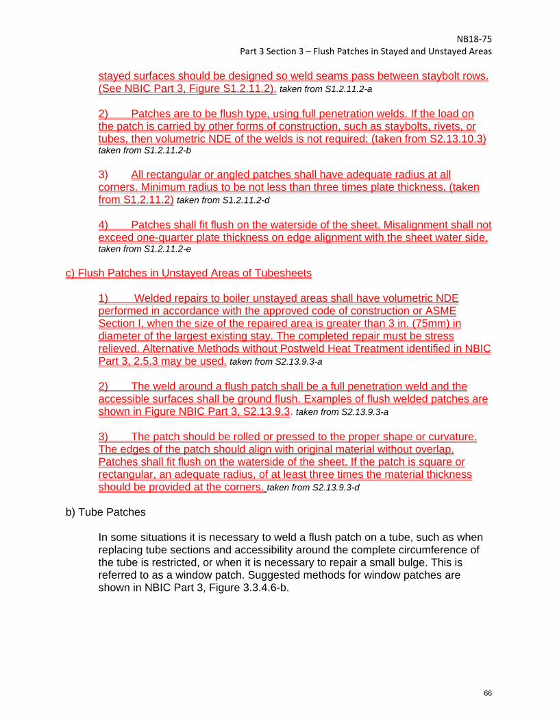
NB18‐75 Part 3 Section 3 – Flush Patches in Stayed and Unstayed Areas
stayed surfaces should be designed so weld seams pass between staybolt rows. (See NBIC Part 3, Figure S1.2.11.2). taken from S1.2.11.2-a
2) Patches are to be flush type, using full penetration welds. If the load on the patch is carried by other forms of construction, such as staybolts, rivets, or tubes, then volumetric NDE of the welds is not required; (taken from S2.13.10.3) taken from S1.2.11.2-b 3) All rectangular or angled patches shall have adequate radius at all corners. Minimum radius to be not less than three times plate thickness. (taken from S1.2.11.2) taken from S1.2.11.2-d 4) Patches shall fit flush on the waterside of the sheet. Misalignment shall not exceed one-quarter plate thickness on edge alignment with the sheet water side. taken from S1.2.11.2-e
c) Flush Patches in Unstayed Areas of Tubesheets
1) Welded repairs to boiler unstayed areas shall have volumetric NDE performed in accordance with the approved code of construction or ASME Section I, when the size of the repaired area is greater than 3 in. (75mm) in diameter of the largest existing stay. The completed repair must be stress relieved. Alternative Methods without Postweld Heat Treatment identified in NBIC Part 3, 2.5.3 may be used. taken from S2.13.9.3-a 2) The weld around a flush patch shall be a full penetration weld and the accessible surfaces shall be ground flush. Examples of flush welded patches are shown in Figure NBIC Part 3, S2.13.9.3. taken from S2.13.9.3-a 3) The patch should be rolled or pressed to the proper shape or curvature. The edges of the patch should align with original material without overlap. Patches shall fit flush on the waterside of the sheet. If the patch is square or rectangular, an adequate radius, of at least three times the material thickness should be provided at the corners. taken from S2.13.9.3-d
b) Tube Patches
In some situations it is necessary to weld a flush patch on a tube, such as when replacing tube sections and accessibility around the complete circumference of the tube is restricted, or when it is necessary to repair a small bulge. This is referred to as a window patch. Suggested methods for window patches are shown in NBIC Part 3, Figure 3.3.4.6-b.
66
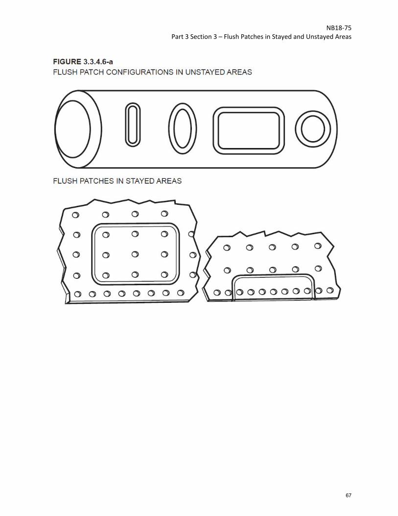
NB18‐75 Part 3 Section 3 – Flush Patches in Stayed and Unstayed Areas
67

NB18‐75 Part 3 Section 3 – Flush Patches in Stayed and Unstayed Areas
68
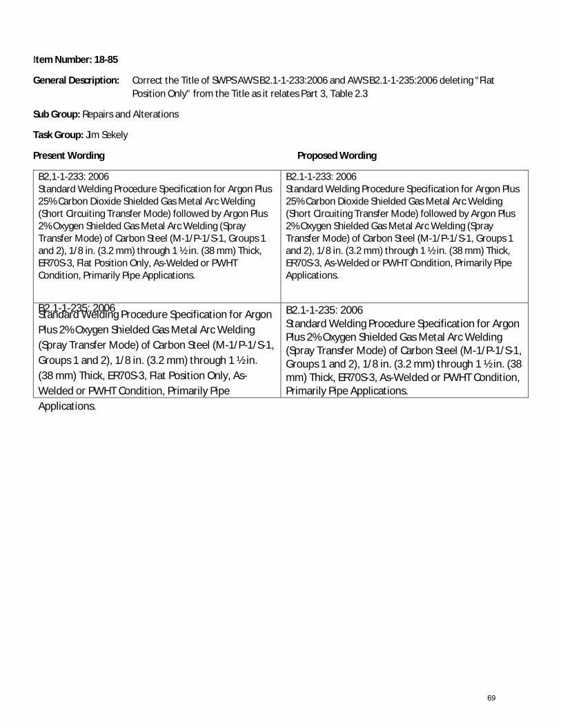
Item Number: 18-85
General Description: Correct the Title of SWPS AWS B2.1-1-233:2006 and AWS B2.1-1-235:2006 deleting “Flat Position Only” from the Title as it relates Part 3, Table 2.3
Sub Group: Repairs and Alterations
Task Group: Jim Sekely
Present Wording Proposed Wording
B2,1-1-233: 2006 Standard Welding Procedure Specification for Argon Plus 25% Carbon Dioxide Shielded Gas Metal Arc Welding (Short Circuiting Transfer Mode) followed by Argon Plus 2% Oxygen Shielded Gas Metal Arc Welding (Spray Transfer Mode) of Carbon Steel (M-1/P-1/S-1, Groups 1 and 2), 1/8 in. (3.2 mm) through 1 ½ in. (38 mm) Thick, ER70S-3, Flat Position Only, As-Welded or PWHT Condition, Primarily Pipe Applications.
B2.1-1-233: 2006 Standard Welding Procedure Specification for Argon Plus 25% Carbon Dioxide Shielded Gas Metal Arc Welding (Short Circuiting Transfer Mode) followed by Argon Plus 2% Oxygen Shielded Gas Metal Arc Welding (Spray Transfer Mode) of Carbon Steel (M-1/P-1/S-1, Groups 1 and 2), 1/8 in. (3.2 mm) through 1 ½ in. (38 mm) Thick, ER70S-3, As-Welded or PWHT Condition, Primarily Pipe Applications.
B2.1-1-235: 2006 Standard Welding Procedure Specification for Argon Plus 2% Oxygen Shielded Gas Metal Arc Welding (Spray Transfer Mode) of Carbon Steel (M-1/P-1/S-1, Groups 1 and 2), 1/8 in. (3.2 mm) through 1 ½ in. (38 mm) Thick, ER70S-3, Flat Position Only, As-Welded or PWHT Condition, Primarily Pipe Applications.
B2.1-1-235: 2006 Standard Welding Procedure Specification for Argon Plus 2% Oxygen Shielded Gas Metal Arc Welding (Spray Transfer Mode) of Carbon Steel (M-1/P-1/S-1, Groups 1 and 2), 1/8 in. (3.2 mm) through 1 ½ in. (38 mm) Thick, ER70S-3, As-Welded or PWHT Condition, Primarily Pipe Applications.
69

INQUIRY FOR ADDITIONAL CODE RULES
Explosive Plugging of Heat Exchanger Tubes
Written By: Marty Russell
Date: 12/20/18
TEi Construction Services, Inc.
170 Tucapau Road Duncan, SC 29334
Office: 864-336-4434
Cell: 864-345-5622
70
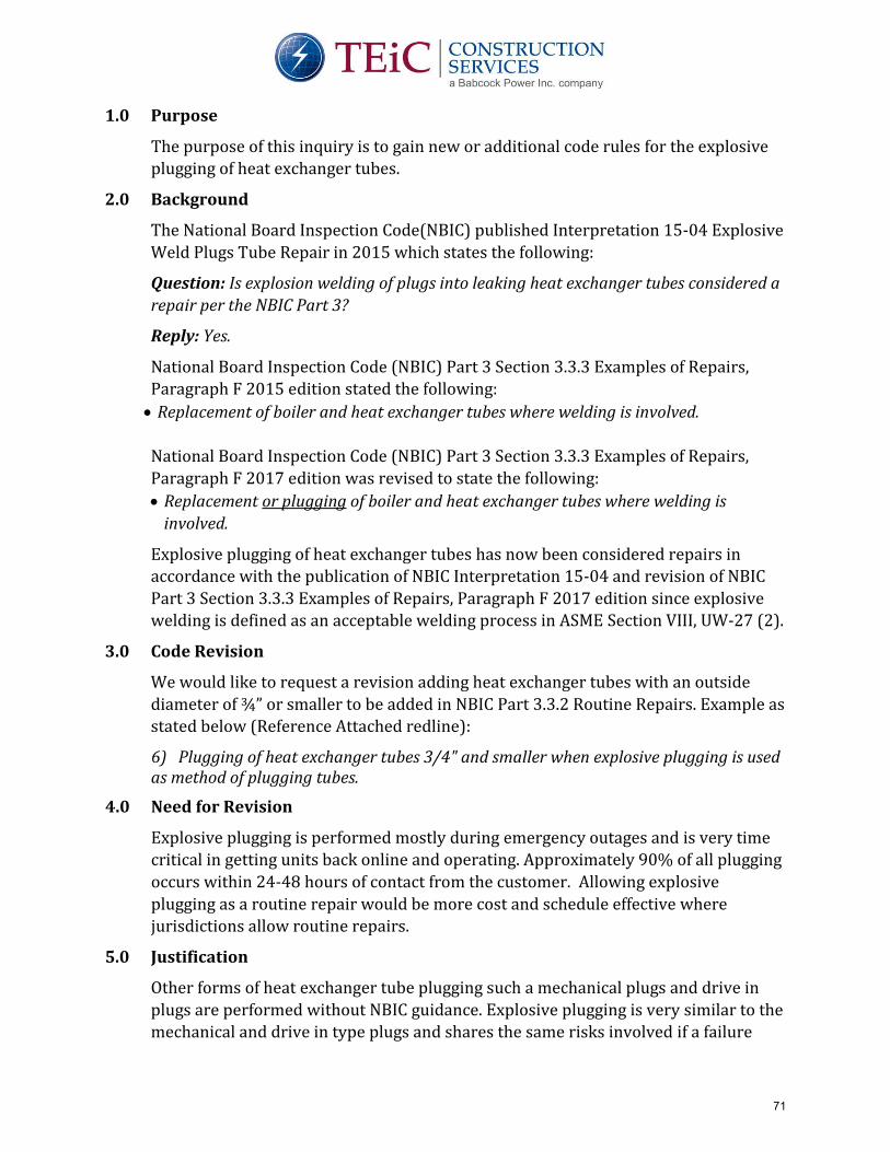
1.0 Purpose
The purpose of this inquiry is to gain new or additional code rules for the explosive
plugging of heat exchanger tubes.
2.0 Background
The National Board Inspection Code(NBIC) published Interpretation 15-04 Explosive
Weld Plugs Tube Repair in 2015 which states the following:
Question: Is explosion welding of plugs into leaking heat exchanger tubes considered a
repair per the NBIC Part 3?
Reply: Yes.
National Board Inspection Code (NBIC) Part 3 Section 3.3.3 Examples of Repairs,
Paragraph F 2015 edition stated the following:
• Replacement of boiler and heat exchanger tubes where welding is involved.
National Board Inspection Code (NBIC) Part 3 Section 3.3.3 Examples of Repairs,
Paragraph F 2017 edition was revised to state the following:
• Replacement or plugging of boiler and heat exchanger tubes where welding is
involved.
Explosive plugging of heat exchanger tubes has now been considered repairs in
accordance with the publication of NBIC Interpretation 15-04 and revision of NBIC
Part 3 Section 3.3.3 Examples of Repairs, Paragraph F 2017 edition since explosive
welding is defined as an acceptable welding process in ASME Section VIII, UW-27 (2).
3.0 Code Revision
We would like to request a revision adding heat exchanger tubes with an outside
diameter of ¾” or smaller to be added in NBIC Part 3.3.2 Routine Repairs. Example as
stated below (Reference Attached redline):
6) Plugging of heat exchanger tubes 3/4" and smaller when explosive plugging is used as method of plugging tubes.
4.0 Need for Revision
Explosive plugging is performed mostly during emergency outages and is very time
critical in getting units back online and operating. Approximately 90% of all plugging
occurs within 24-48 hours of contact from the customer. Allowing explosive
plugging as a routine repair would be more cost and schedule effective where
jurisdictions allow routine repairs.
5.0 Justification
Other forms of heat exchanger tube plugging such a mechanical plugs and drive in
plugs are performed without NBIC guidance. Explosive plugging is very similar to the
mechanical and drive in type plugs and shares the same risks involved if a failure
71
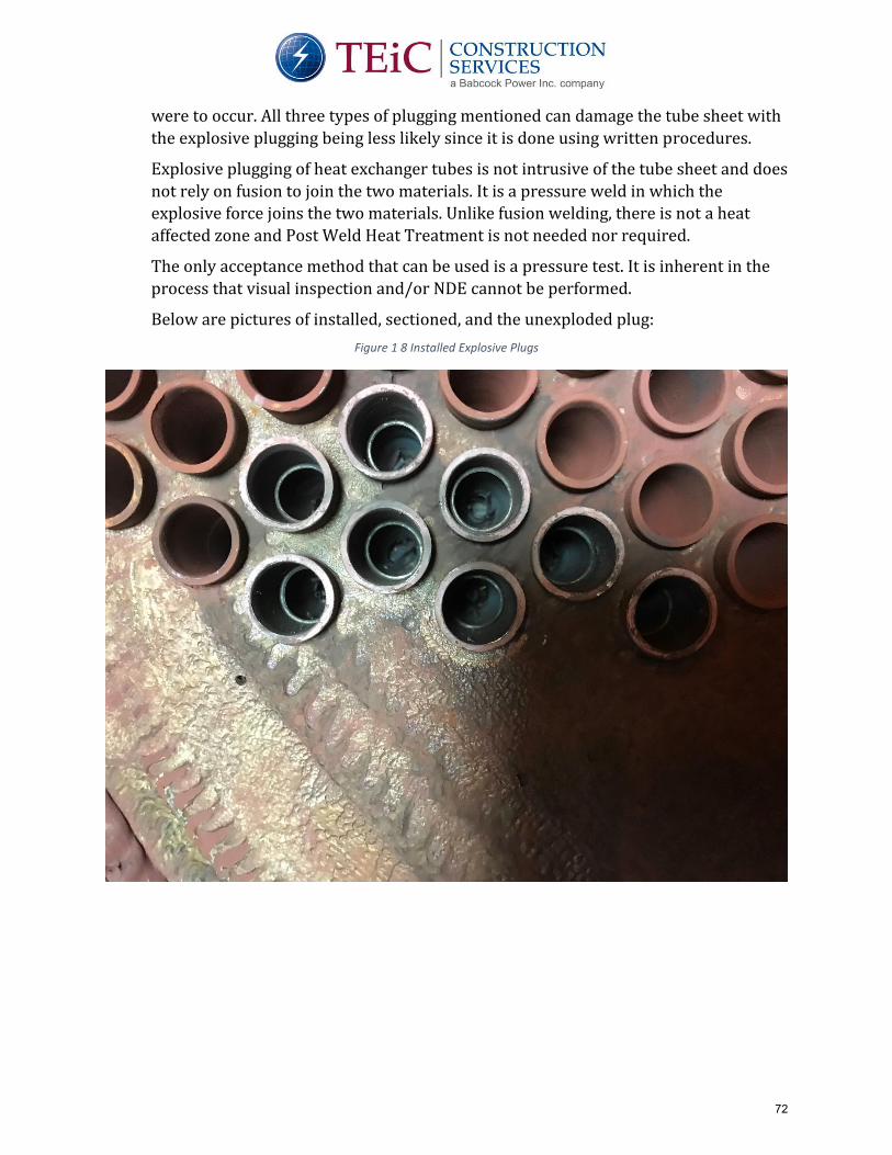
were to occur. All three types of plugging mentioned can damage the tube sheet with
the explosive plugging being less likely since it is done using written procedures.
Explosive plugging of heat exchanger tubes is not intrusive of the tube sheet and does
not rely on fusion to join the two materials. It is a pressure weld in which the
explosive force joins the two materials. Unlike fusion welding, there is not a heat
affected zone and Post Weld Heat Treatment is not needed nor required.
The only acceptance method that can be used is a pressure test. It is inherent in the
process that visual inspection and/or NDE cannot be performed.
Below are pictures of installed, sectioned, and the unexploded plug:
Figure 1 8 Installed Explosive Plugs
72

Figure 2 Sectioned Samples of Explosive Plugs After Installation
Figure 3 Explosive Plug Prior To Installation
73

Videos of the explosive plugging process can be obtained by contacting Marty Russell
at the numbers or email listed on the cover page. I would like to thank you for your
time and we are looking forward to hearing from you on this inquiry.
Attachments:
2015 Interpretation 15-04
NBIC 2015 Paragraph 3.3.3 f)
NBIC 2017 Paragraph 3.3.3 f)
ASME Section VIII Div. 1 UW-27
NBIC 2017 Paragraph 3.3.3 Redline of Revision
Regards,
Marty Russell
Quality Program Manager
TEiC Heat Exchanger Services
Email: [email protected]
Office: 864-336-4434
Cell: 864-345-5622
74
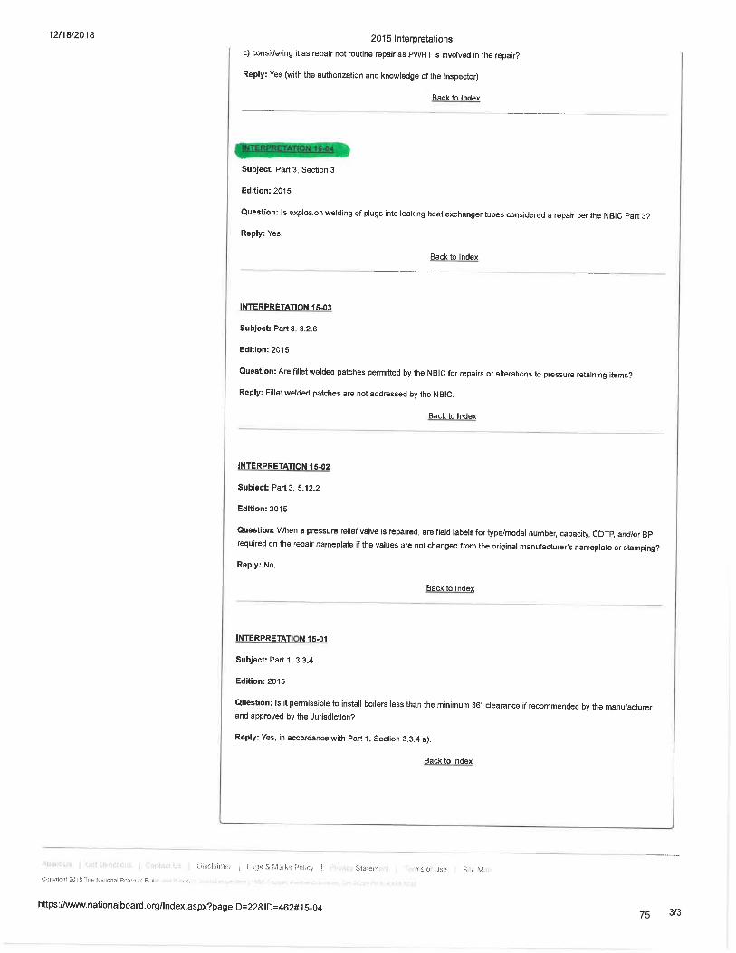
75
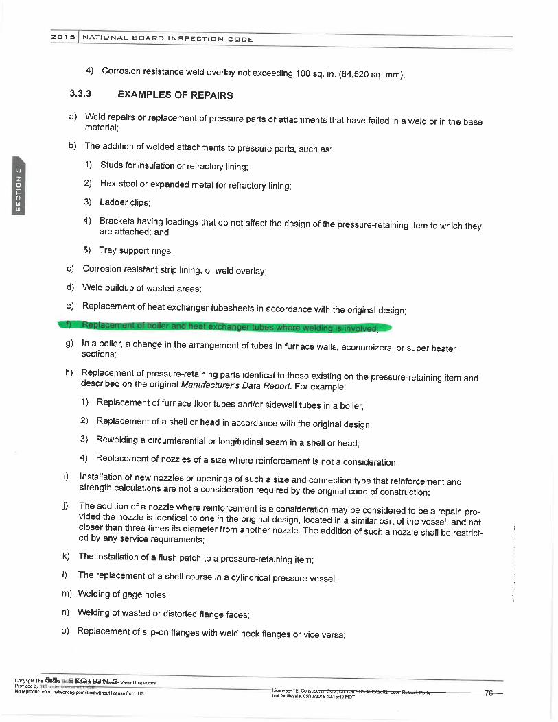
76
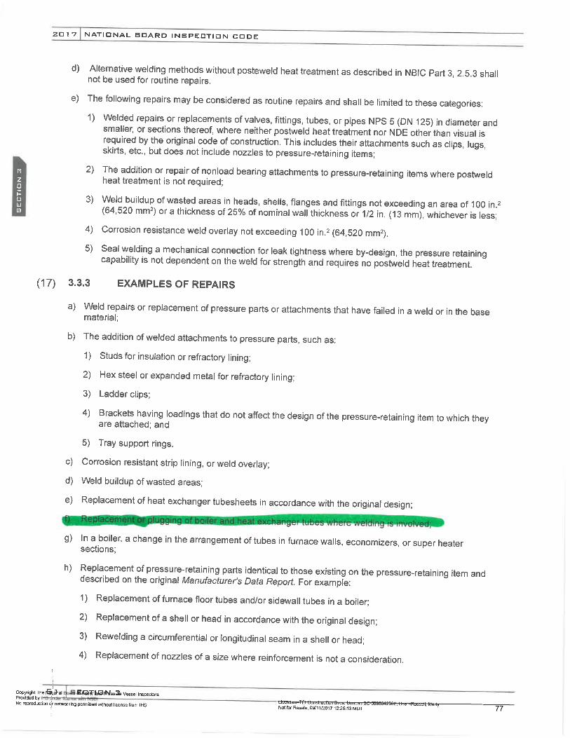
77

78

79

80

81
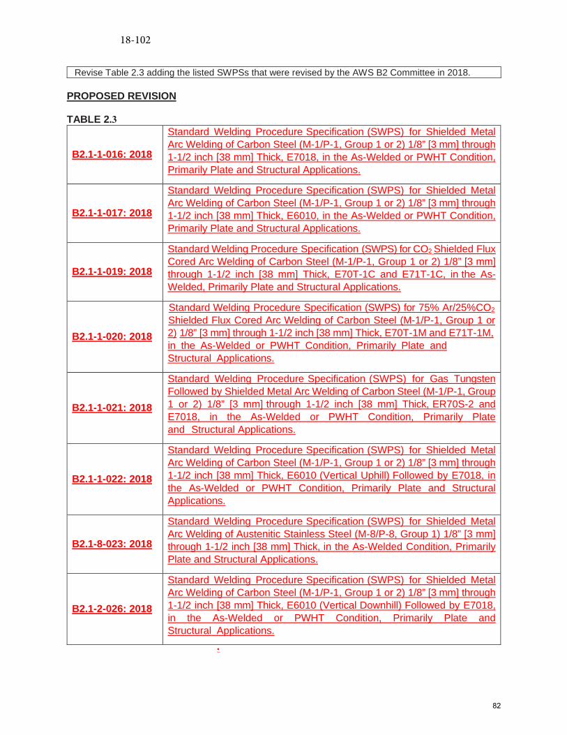
Revise Table 2.3 adding the listed SWPSs that were revised by the AWS B2 Committee in 2018.
PROPOSED REVISION
TABLE 2.3
B2.1-1-016: 2018
Standard Welding Procedure Specification (SWPS) for Shielded Metal Arc Welding of Carbon Steel (M-1/P-1, Group 1 or 2) 1/8” [3 mm] through 1-1/2 inch [38 mm] Thick, E7018, in the As-Welded or PWHT Condition, Primarily Plate and Structural Applications.
B2.1-1-017: 2018
Standard Welding Procedure Specification (SWPS) for Shielded Metal Arc Welding of Carbon Steel (M-1/P-1, Group 1 or 2) 1/8” [3 mm] through 1-1/2 inch [38 mm] Thick, E6010, in the As-Welded or PWHT Condition, Primarily Plate and Structural Applications.
B2.1-1-019: 2018
Standard Welding Procedure Specification (SWPS) for CO2 Shielded Flux Cored Arc Welding of Carbon Steel (M-1/P-1, Group 1 or 2) 1/8” [3 mm] through 1-1/2 inch [38 mm] Thick, E70T-1C and E71T-1C, in the As-Welded, Primarily Plate and Structural Applications.
B2.1-1-020: 2018
Standard Welding Procedure Specification (SWPS) for 75% Ar/25%CO2 Shielded Flux Cored Arc Welding of Carbon Steel (M-1/P-1, Group 1 or 2) 1/8” [3 mm] through 1-1/2 inch [38 mm] Thick, E70T-1M and E71T-1M,in the As-Welded or PWHT Condition, Primarily Plate and Structural Applications.
B2.1-1-021: 2018
Standard Welding Procedure Specification (SWPS) for Gas Tungsten Followed by Shielded Metal Arc Welding of Carbon Steel (M-1/P-1, Group 1 or 2) 1/8” [3 mm] through 1-1/2 inch [38 mm] Thick, ER70S-2 and E7018, in the As-Welded or PWHT Condition, Primarily Plate and Structural Applications.
B2.1-1-022: 2018
Standard Welding Procedure Specification (SWPS) for Shielded Metal Arc Welding of Carbon Steel (M-1/P-1, Group 1 or 2) 1/8” [3 mm] through 1-1/2 inch [38 mm] Thick, E6010 (Vertical Uphill) Followed by E7018, in the As-Welded or PWHT Condition, Primarily Plate and Structural Applications.
B2.1-8-023: 2018
Standard Welding Procedure Specification (SWPS) for Shielded Metal Arc Welding of Austenitic Stainless Steel (M-8/P-8, Group 1) 1/8” [3 mm] through 1-1/2 inch [38 mm] Thick, in the As-Welded Condition, Primarily Plate and Structural Applications.
B2.1-2-026: 2018
Standard Welding Procedure Specification (SWPS) for Shielded Metal Arc Welding of Carbon Steel (M-1/P-1, Group 1 or 2) 1/8” [3 mm] through 1-1/2 inch [38 mm] Thick, E6010 (Vertical Downhill) Followed by E7018, in the As-Welded or PWHT Condition, Primarily Plate and Structural Applications.
·
18-102
82

83
84

85
86

87

88

89
90

91

92

93

94
95

96
97

98

Item 19‐11 – Withers – 01‐22‐2019
Location: Section 9 of Parts 1, 2, 3 and 4
Explanation of Need: Clarify Definition of Authorized Nuclear Inspection Agency (ANIA) ‐ NBIC Glossary
Section 9
Background: An ANIA can not be an Inservice AIA since Endorsements for nuclear inspectors are issued
only to new construction AIA’s. The requirements for qualified Authorized Nuclear
Inspectors/Supervisors are clearl specified in NB‐263, RCI‐1. Therefore revision to the Glossary definition
is needed to clarify this requirement for the NR Accreditation Program.
Existing Text: Authorized Nuclear Inspection Agency — An Authorized Inspection Agency intending to
perform nuclear inspection activities and employing nuclear Inspectors / Supervisors
Proposed Text: Authorized Nuclear Inspection Agency – An New Construction Authorized Inspection
Agency intending to perform nuclear inspection activities and employing qualified Authorized nNuclear
Inspectors/Supervisors.
99

Item 19‐12 – Withers – 01‐22‐2019
NBIC NR Revisions.
Paragraph 1.6.3 – revise text to clarify Quality Assurance Program requirements:
Existing Text;
b) Have a written Quality Assurance Program that complies with the requirements of this section and
address all controls for the intended category and scope of activities.
Revised text;
b) Have a written Quality Assurance Program that complies with the requirements of which includes the
quality assurance manual and any supporting procedures, instructions and specifications required to
comply with this section. The Quality Assurance Program shall and address all controls for the intended
category and scope of activities requested.
100

Item 19‐13 – Withers – 01‐22‐2019
NBIC NR Revisions.
Explanation of Need: Revise text to clarify responsibilities for performing audits between the Certificate
Holder and the AIA.
Location: Paragraph’s 1.6.6.2 s); 1.6.7.2 s); and 1.6.8.2 s) AUDITS
The provisions identified in ASME NQA‐1, Part 1, and Requirement 18 shall apply and shall include the
following:
A comprehensive system of planned and periodic audits of the NR Certificate Holder’s Quality Assurance
Program shall be performed. Audits shall include internal audits by the Certificate Holder and audits by
the Authorized Inspection Agency. Audit frequency shall be specified in the organization’s Quality
Assurance Manual. Audits shall be conducted at least annually (within 12 months) for any ongoing code
activity to verify compliance with the Quality Assurance Program requirements, performed criteria, and
to determine the effectiveness of the Quality Assurance Program. When no code work has been
performed, the required annual audit need only include those areas of responsibility required to be
continually maintained such as training, audits, organizational structure, and Quality Assurance Program
revisions. The Quality Assurance Manual shall as a minimum describe the following:
a. Audits shall be performed in accordance with written procedures or checklists by qualified audit
personnel not having direct responsibility in areas being audited;
b. Audit personnel shall be qualified in accordance with the current requirements of ASME NQA‐1;
c. Audit results shall be documented and reviewed by responsible management for adequacy and
effectiveness of the quality assurance program;
d. Requirements for follow‐up actions shall be specified for any deficiencies noted during the
audit;
e. Audit records and applicable documentation shall be made available to the Authorized Nuclear
Inspectorion Agency for review;
f. Audit records shall include as a minimum;
i. Written procedures
ii. Checklists;
iii. Reports;
iv. Written replies; and
v. Completion of corrective actions.
Performance of Authorized Inspection Agency audits required by ASME QAI‐1 and NB‐263, RCI‐1 shall be
addressed in the Quality Assurance Manual. When no Code work has been performed within the past
year, required audits for ANI performance by the ANIS is not required. However, an annual audit of the
NR Certificate Holder’s Quality Assurance Manual shall be performed and only need to include those
areas of responsibility required to be maintained by the Certificate Holder as stated above.
101
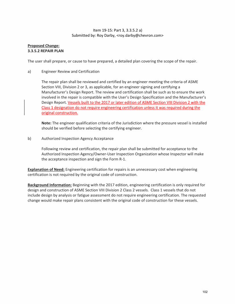
Item 19‐15: Part 3, 3.3.5.2 a) Submitted by: Roy Darby, <[email protected]>
Proposed Change: 3.3.5.2 REPAIR PLAN The user shall prepare, or cause to have prepared, a detailed plan covering the scope of the repair. a) Engineer Review and Certification
The repair plan shall be reviewed and certified by an engineer meeting the criteria of ASME Section VIII, Division 2 or 3, as applicable, for an engineer signing and certifying a Manufacturer’s Design Report. The review and certification shall be such as to ensure the work involved in the repair is compatible with the User’s Design Specification and the Manufacturer’s Design Report. Vessels built to the 2017 or later edition of ASME Section VIII Division 2 with the Class 1 designation do not require engineering certification unless it was required during the original construction.
Note: The engineer qualification criteria of the Jurisdiction where the pressure vessel is installed should be verified before selecting the certifying engineer.
b) Authorized Inspection Agency Acceptance
Following review and certification, the repair plan shall be submitted for acceptance to the Authorized Inspection Agency/Owner‐User Inspection Organization whose Inspector will make the acceptance inspection and sign the Form R‐1.
Explanation of Need: Engineering certification for repairs is an unnecessary cost when engineering certification is not required by the original code of construction. Background Information: Beginning with the 2017 edition, engineering certification is only required for design and construction of ASME Section VIII Division 2 Class 2 vessels. Class 1 vessels that do not include design by analysis or fatigue assessment do not require engineering certification. The requested change would make repair plans consistent with the original code of construction for these vessels.
102
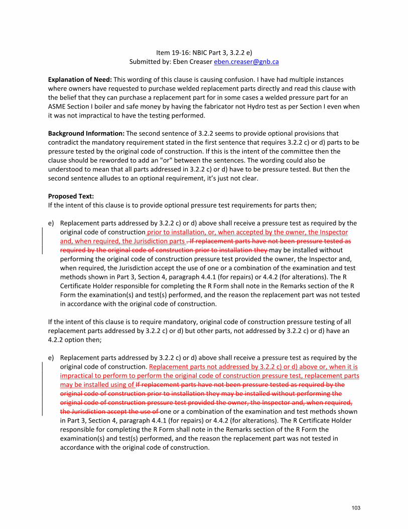
Item 19‐16: NBIC Part 3, 3.2.2 e) Submitted by: Eben Creaser [email protected]
Explanation of Need: This wording of this clause is causing confusion. I have had multiple instances where owners have requested to purchase welded replacement parts directly and read this clause with the belief that they can purchase a replacement part for in some cases a welded pressure part for an ASME Section I boiler and safe money by having the fabricator not Hydro test as per Section I even when it was not impractical to have the testing performed. Background Information: The second sentence of 3.2.2 seems to provide optional provisions that contradict the mandatory requirement stated in the first sentence that requires 3.2.2 c) or d) parts to be pressure tested by the original code of construction. If this is the intent of the committee then the clause should be reworded to add an "or" between the sentences. The wording could also be understood to mean that all parts addressed in 3.2.2 c) or d) have to be pressure tested. But then the second sentence alludes to an optional requirement, it’s just not clear. Proposed Text: If the intent of this clause is to provide optional pressure test requirements for parts then; e) Replacement parts addressed by 3.2.2 c) or d) above shall receive a pressure test as required by the
original code of construction prior to installation, or, when accepted by the owner, the Inspector and, when required, the Jurisdiction parts . If replacement parts have not been pressure tested as required by the original code of construction prior to installation they may be installed without performing the original code of construction pressure test provided the owner, the Inspector and, when required, the Jurisdiction accept the use of one or a combination of the examination and test methods shown in Part 3, Section 4, paragraph 4.4.1 (for repairs) or 4.4.2 (for alterations). The R Certificate Holder responsible for completing the R Form shall note in the Remarks section of the R Form the examination(s) and test(s) performed, and the reason the replacement part was not tested in accordance with the original code of construction.
If the intent of this clause is to require mandatory, original code of construction pressure testing of all replacement parts addressed by 3.2.2 c) or d) but other parts, not addressed by 3.2.2 c) or d) have an 4.2.2 option then; e) Replacement parts addressed by 3.2.2 c) or d) above shall receive a pressure test as required by the
original code of construction. Replacement parts not addressed by 3.2.2 c) or d) above or, when it is impractical to perform to perform the original code of construction pressure test, replacement parts may be installed using of If replacement parts have not been pressure tested as required by the original code of construction prior to installation they may be installed without performing the original code of construction pressure test provided the owner, the Inspector and, when required, the Jurisdiction accept the use of one or a combination of the examination and test methods shown in Part 3, Section 4, paragraph 4.4.1 (for repairs) or 4.4.2 (for alterations). The R Certificate Holder responsible for completing the R Form shall note in the Remarks section of the R Form the examination(s) and test(s) performed, and the reason the replacement part was not tested in accordance with the original code of construction.
103
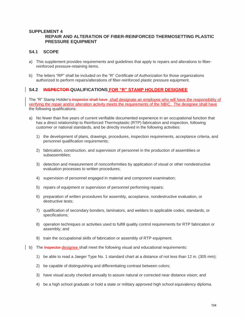
SUPPLEMENT 4 REPAIR AND ALTERATION OF FIBER-REINFORCED THERMOSETTING PLASTIC PRESSURE EQUIPMENT
S4.1 SCOPE a) This supplement provides requirements and guidelines that apply to repairs and alterations to fiber-
reinforced pressure-retaining items.
b) The letters “RP” shall be included on the “R” Certificate of Authorization for those organizations authorized to perform repairs/alterations of fiber-reinforced plastic pressure equipment.
S4.2 INSPECTOR QUALIFICATIONS FOR “R” STAMP HOLDER DESIGNEE The “R” Stamp Holder’s inspector shall have shall designate an employee who will have the responsibility of verifying the repair and/or alteration activity meets the requirements of the NBIC. The designee shall have the following qualifications: a) No fewer than five years of current verifiable documented experience in an occupational function that
has a direct relationship to Reinforced Thermoplastic (RTP) fabrication and inspection, following customer or national standards, and be directly involved in the following activities:
1) the development of plans, drawings, procedures, inspection requirements, acceptance criteria, and
personnel qualification requirements;
2) fabrication, construction, and supervision of personnel in the production of assemblies or subassemblies;
3) detection and measurement of nonconformities by application of visual or other nondestructive evaluation processes to written procedures;
4) supervision of personnel engaged in material and component examination;
5) repairs of equipment or supervision of personnel performing repairs;
6) preparation of written procedures for assembly, acceptance, nondestructive evaluation, or destructive tests;
7) qualification of secondary bonders, laminators, and welders to applicable codes, standards, or specifications;
8) operation techniques or activities used to fulfill quality control requirements for RTP fabrication or assembly; and
9) train the occupational skills of fabrication or assembly of RTP equipment. b) The Inspector designee shall meet the following visual and educational requirements:
1) be able to read a Jaeger Type No. 1 standard chart at a distance of not less than 12 in. (305 mm);
2) be capable of distinguishing and differentiating contrast between colors;
3) have visual acuity checked annually to assure natural or corrected near distance vision; and
4) be a high school graduate or hold a state or military approved high school equivalency diploma.
104

c) The employer of the inspector”R” Certificate Holder shall certify that the employee designee complies with the above qualification requirements.
SUPPL. 4
S4.3 TOOLS The following tools may be required by the InspectorR Stamp Holder’s designee.: a) adequate lighting including overall lighting and a portable lamp for close inspections; b) handheld magnifying glass; c) Barcol hardness tester; d) small pick or pen knife; e) small quantity of acetone and cotton swabs; f) camera with flash capability; and g) liquid penetrant testing kit. S4.4 LIMITATIONS All field work shall be limited to secondary bonding.
105

Item 19-21: Part 3, S2.11 a) S2.11 NONDESTRUCTIVE EXAMINATION a) The Inspector may require nondestructive examination (RT, PT, MT, UT, and VT) as necessary to ensure satisfactory welded repairs and alterations have been accomplished. (See NBIC Part 3, 4.2) b) The nondestructive examination (NDE) requirements, including technique, extent of coverage, procedures, personnel qualification, and acceptance criteria, shall be in accordance with the original code of construction for the pressure-retaining item. Weld repairs and alterations shall be subjected to the same nondestructive examination requirements as the original welds. c) Where the original code of construction is unknown or the NDE method is not possible or practicable, alternative NDE methods may be used. These methods shall be acceptable to the owner, the Inspector and where required, the Jurisdiction of the pressure-retaining item. d) NDE methods used shall be suitable for providing meaningful results to verify the integrity of the repair and or alteration. e) Exclusive use of visual examination (VT) for repair inspection is only permitted when following the requirements of Part 3, 4.4.1 e).
106
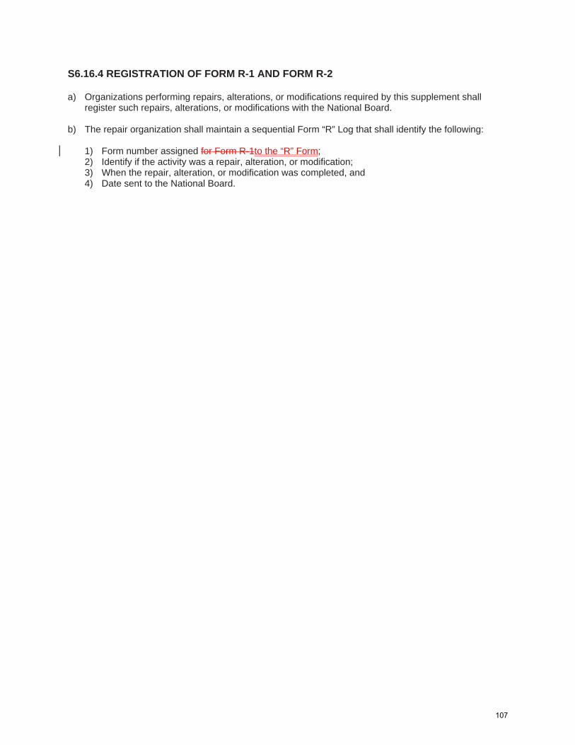
S6.16.4 REGISTRATION OF FORM R-1 AND FORM R-2 a) Organizations performing repairs, alterations, or modifications required by this supplement shall
register such repairs, alterations, or modifications with the National Board. b) The repair organization shall maintain a sequential Form “R” Log that shall identify the following:
1) Form number assigned for Form R-1to the “R” Form; 2) Identify if the activity was a repair, alteration, or modification; 3) When the repair, alteration, or modification was completed, and 4) Date sent to the National Board.
107

32
2019
SECTION 2
SEC
TIO
N 2
NB-23
tanda d e d n ced e pec ca n e ded eta c e d n a n tee p n t n c
e ca n ed e ca p e ded nd n a pe pp ca n
and
tanda d e d n ced e pec ca n e ded eta c e d n a n tee p n t n c
e ded nd n a pe pp ca ntanda d e d n ced e pec ca n e ded eta c e d n a n tee p n t n c
e ded nd n a pe pp ca n
GTAW — Gas Tungsten Arc Weldingtanda d e d n ced e pec ca n a n ten c e d n a n tee p n t n c n t e e ded nd n t t t ac n
and
tanda d e d n ced e pec ca n a n ten c e d n a n tee p n t n c
e ded nd n a pe pp ca ntanda d e d n ced e pec ca n a n ten c e d n a n tee
p n t n c e ded nd n a pe pp ca n
tanda d e d n ced e pec ca n a n ten c e d n n a e n e t a n tee p n t n
c and e ded nd n a pe pp ca ntanda d e d n ced e pec ca n a n ten c e d n t
n a e n e t t a n tee p n t n c e ded nd n
a pe pp ca n
FCAW — Flux Core Arc Weldingtanda d e d n ced e pec ca n e e ded F ed c e d n a n tee p n t n
c e ded nd n
and
tanda d e d n ced e pec ca n e ded F ed c e d n a n tee p n t n c and e ded nd n
and and
tanda d e d n ced e pec ca n e ded F ed c e d n a n tee p n t n
c and e ded nd n
and and
tanda d e d n ced e e e ded F ed c e d n a n tee p n t n c
e ded nd n
and
tanda d e d n ced e pec ca n n a n de e ded F ed c e d n a n tee p and
n t n c e ded nd n a pe pp ca n
The 2007 revision changed the range to a max of 1 1/2 in. Make separate lineitem.
should be 1 1/2 in.
should be 1 1/2 in.
should be 1 1/2 in.
1995 version wasqualified to 3/4 in.Make separate lineitem.
108

33
NATIONAL BOARD INSPECTION CODE2019
SECTION 2
SEC
TIO
N 2
GMAW – Gas Metal Arc Weldingtanda d e d n ced e pec ca n n a n de e ded a eta c e d n t c n an e de ed n
en e ded a eta c e d n p a an e de a n tee p and n t n c
F at n n e ded nd n a pe pp ca n
tanda d e d n ced e pec ca n n en e ded a eta c e d n p a an e de a n tee p and
n t n c F at n n e ded nd n a pe pp ca n
GTAW SMAW Com ina on o Welding rocessestanda d e d n ced e pec ca n a n ten c e d n F ed
e ded eta c e d n a n tee p n t n c and e ded nd n
and
tanda d e d n ced e pec ca n a n ten c e d n ed e ded eta c e d n a n tee p n
t n c and e ded nd n a pe pp ca n
tanda d e d n ced e pec ca n a n ten c e d n ed e ded eta c e d n a n tee p n
t n c and e ded nd n a pe pp ca n
tanda d e d n ced e pec ca n a n ten c e d n n a e n e t F ed e ded eta c e d n a n tee p
n t n c and e ded nd n a pe pp ca n
tanda d e d n ced e pec ca n a n ten c e d n t n a e n e t t F ed e ded eta c e d n a n tee
p n t n c and e ded nd n a pe pp ca n
GMAW FCAW – Com ina on o Welding rocessestanda d e d n ced e pec ca n n a n de e ded a eta c e d n t c n an e de F ed n a n de e ded F ed c e d n a n tee p and n t n c and e ded nd n a pe pp ca n
Austenitic Stainless Steel — (M8/P8/S8 Materials)
SMAW — Shielded Metal Arc Weldingtanda d e d n ced e pec ca n e ded eta c e d n ten c ta n e tee p n t n c
e ded nd n
tanda d e d n ced e pec ca n e ded eta c e d n ten c ta n e tee p n t n c
e ded nd n a pe pp ca n
and
should be 1 1/2 in.
should be 1 1/2 in.
97
109

34
2019
SECTION 2
SEC
TIO
N 2
NB-23
GTAW — Gas Tungsten Arc Weldingtanda d e d n ced e pec ca n a n ten c e d n ten c ta n e tee p n t n c
e ded nd ntanda d e d n ced e pec ca n a n ten c e d n ten c ta n e tee p n t n c
e ded nd n a ate and t ct a pp ca ntanda d e d n ced e pec ca n a n ten c e d n ten c ta n e tee p n t n c
e ded nd n a pe pp ca ntanda d e d n ced e pec ca n a n ten c e d n ten c ta n e tee p n t n t c
e ded nd n a pe pp ca n
tanda d e d n ced e pec ca n a n ten c e d n t n a e n e t t ten c ta n e tee p n
t n c and e ded nd n a pe pp ca n
Com ina on rocesses GTAW SMAWtanda d e d n ced e pec ca n a n ten c e d n ed
e ded eta c e d n ten c ta n e tee p n t n c e ded nd n
tanda d e d n ced e pec ca n a n ten c e d n ed e ded eta c e d n ten c ta n e tee p
n t n c and e ded nd n a ate and t ct a pp ca n
tanda d e d n ced e pec ca n a n ten c e d n F ed e ded eta c e d n ten c ta n e tee p
n t n c and e ded nd n a pe pp ca n
tanda d e d n ced e pec ca n a n ten c e d n F ed e ded eta c e d n ten c ta n e tee p
n t n c and e ded nd n a pe pp ca n
tanda d e d n ced e pec ca n a n ten c e d n t n a e n e t F ed e ded eta c e d n ten c ta n e tee
p n t n t c and e ded nd n a pe pp ca n
tanda d e d n ced e pec ca n a n ten c e d n t n a e n e t t ed e ded eta c e d n ten c ta n e
tee p n t n c and e ded nd n a pe pp ca n
Combination of Carbon Steel (P-1 Material) To Austenitic Stainless Steel (P-8 Material)
SMAW — Shielded Metal Arc Weldingtanda d e d n ced e pec ca n e ded eta c e d n a n tee p t ten c ta n e tee p
n t n c e ded nd n a pe pp ca n
Should be 1/8 in.
110

35
NATIONAL BOARD INSPECTION CODE2019
SECTION 2
SEC
TIO
N 2
GTAW — Gas Tungsten Arc Weldingtanda d e d n ced e pec ca n a n ten c e d n a n tee p t ten c ta n e tee p
n t n c e ded nd n a pe pp ca n
and
tanda d e d n ced e pec ca n a n ten c e d n t n a e n e t t a n tee p t ten c
ta n e tee p n t n c and e ded nd n a pe pp ca n
and
GTAW SMAW Com ina on o Welding rocessestanda d e d n ced e pec ca n a n ten c e d n ed
e ded eta c e d n a n tee p t ten c ta n e tee p n t n
c and e ded nd n a pe pp ca n
and
tanda d e d n ced e pec ca n a n ten c e d n t n a e n e t t ed e ded eta c e d n a n tee
p t ten c ta n e tee p n t n c and
and e ded nd n a pe pp ca n
Chromium Molybdenum Steel (M4/P4 and M5a/P5A Materials)
SMAW — Shielded Metal Arc Weldingtanda d e d n ced e pec ca n e ded eta c e d n
den tee p n t n c e ded nd n n t n
c nd n a pe pp ca n
tanda d e d n ced e pec ca n e ded eta c e d n den tee n t
n c e ded nd n n t n c nd n a pe pp ca n
GTAW — Gas Tungsten Arc Weldingtanda d e d n ced e pec ca n a n ten c e d n
den tee p n t n c e ded nd n n t n
c nd n a pe pp ca n
tanda d e d n ced e pec ca n a n ten c e d n n a e n e t t den tee p
n t n c e ded nd n n t n c nd n and
a pe pp ca n
tanda d e d n ced e pec ca n a n ten c e d n den tee n t
n c e ded nd n n t n c nd n a pe pp ca n
Should be 1/2 in.
111
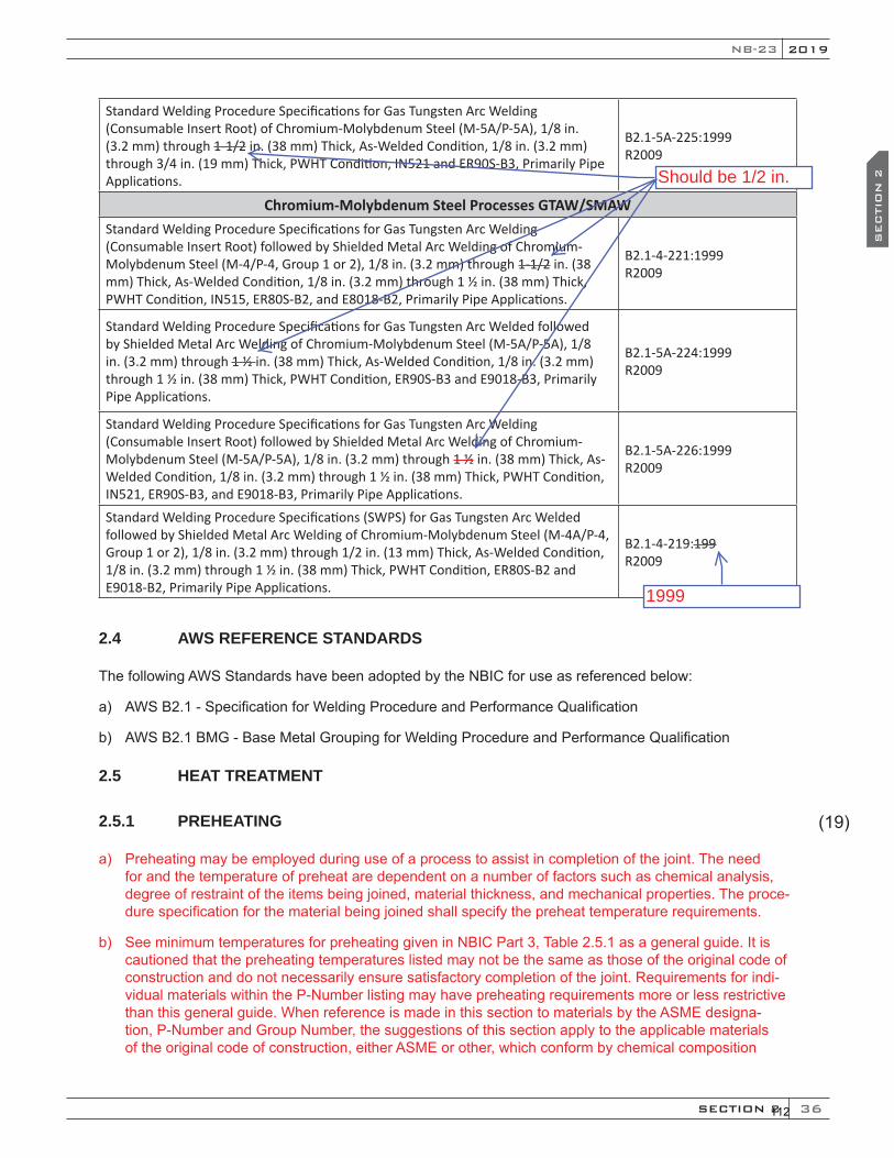
36
2019
SECTION 2
SEC
TIO
N 2
NB-23
tanda d e d n ced e pec ca n a n ten c e d n n a e n e t t den tee n t n c e ded nd n n
t n c nd n and a pe pp ca n
Chromium Mol denum Steel rocesses GTAW SMAWtanda d e d n ced e pec ca n a n ten c e d n
n a e n e t t ed e ded eta c e d n den tee p n t n
c e ded nd n n t n c nd n and a pe pp ca n
tanda d e d n ced e pec ca n a n ten c e ded ed e ded eta c e d n den tee
n t n c e ded nd n n t n c nd n and a
pe pp ca n
tanda d e d n ced e pec ca n a n ten c e d n n a e n e t t ed e ded eta c e d n
den tee n t n c e ded nd n n t n c nd n
and a pe pp ca n
tanda d e d n ced e pec ca n a n ten c e ded ed e ded eta c e d n den tee
p n t n c e ded nd n n t n c nd n and
a pe pp ca n
2.4 AWS REFERENCE STANDARDS
The following AWS Standards have been adopted by the N IC for use as referenced below:
a) AWS .1 - Speci cation for Welding Procedure and Performance uali cation
b) AWS .1 M - ase Metal rouping for Welding Procedure and Performance uali cation
2.5 HEAT TREATMENT
2.5.1 PREHEATING
a) Preheating may be employed during use of a process to assist in completion of the oint. The needfor and the temperature of preheat are dependent on a number of factors such as chemical analysis,degree of restraint of the items being oined, material thic ness, and mechanical properties. The proce-dure speci cation for the material being oined shall specify the preheat temperature requirements.
b) See minimum temperatures for preheating given in N IC Part , Table . .1 as a general guide. It iscautioned that the preheating temperatures listed may not be the same as those of the original code ofconstruction and do not necessarily ensure satisfactory completion of the oint. Requirements for indi-vidual materials within the P-Number listing may have preheating requirements more or less restrictivethan this general guide. When reference is made in this section to materials by the ASME designa-tion, P-Number and roup Number, the suggestions of this section apply to the applicable materialsof the original code of construction, either ASME or other, which conform by chemical composition
(19)
Should be 1/2 in.
1999
112

Item 19‐32: NBIC Part 3, 3.3.2 and 3.4.4 Submitted by: Paul Shanks [email protected]
Explanation of Need: When heater treaters and some other similar equipment is constructed in accordance with section VIII div.1 an item called a fire tube is often removable (bolted) and should be part of the code boundary. In use these items are consumables and are replaced often with items not bearing the code markings or manufactured to code practices. This practice places the users and public in jeopardy and should be curtailed. Background Information: ASME VIII Div.1 allows for the code boundary to terminate at a flange face only when connecting to external piping or other code items, if a code fire tube is replace with a none code item the ASME construction code has been violated and the potential for harm is increased. Please be aware that ASME has a task group focused on clarifying the requirements for fire tubes. https://www.glossary.oilfield.slb.com/en/Terms/h/heater_treater.aspx Proposed Text Changes: see following pages
113
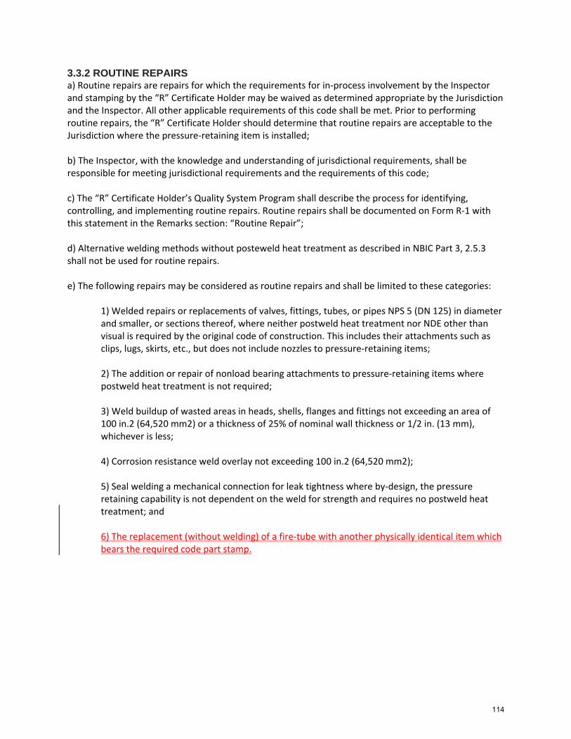
3.3.2 ROUTINE REPAIRS a) Routine repairs are repairs for which the requirements for in‐process involvement by the Inspector and stamping by the “R” Certificate Holder may be waived as determined appropriate by the Jurisdiction and the Inspector. All other applicable requirements of this code shall be met. Prior to performing routine repairs, the “R” Certificate Holder should determine that routine repairs are acceptable to the Jurisdiction where the pressure‐retaining item is installed; b) The Inspector, with the knowledge and understanding of jurisdictional requirements, shall be responsible for meeting jurisdictional requirements and the requirements of this code; c) The “R” Certificate Holder’s Quality System Program shall describe the process for identifying, controlling, and implementing routine repairs. Routine repairs shall be documented on Form R‐1 with this statement in the Remarks section: “Routine Repair”; d) Alternative welding methods without posteweld heat treatment as described in NBIC Part 3, 2.5.3 shall not be used for routine repairs. e) The following repairs may be considered as routine repairs and shall be limited to these categories:
1) Welded repairs or replacements of valves, fittings, tubes, or pipes NPS 5 (DN 125) in diameter and smaller, or sections thereof, where neither postweld heat treatment nor NDE other than visual is required by the original code of construction. This includes their attachments such as clips, lugs, skirts, etc., but does not include nozzles to pressure‐retaining items; 2) The addition or repair of nonload bearing attachments to pressure‐retaining items where postweld heat treatment is not required; 3) Weld buildup of wasted areas in heads, shells, flanges and fittings not exceeding an area of 100 in.2 (64,520 mm2) or a thickness of 25% of nominal wall thickness or 1/2 in. (13 mm), whichever is less; 4) Corrosion resistance weld overlay not exceeding 100 in.2 (64,520 mm2); 5) Seal welding a mechanical connection for leak tightness where by‐design, the pressure retaining capability is not dependent on the weld for strength and requires no postweld heat treatment; and 6) The replacement (without welding) of a fire‐tube with another physically identical item which bears the required code part stamp.
114
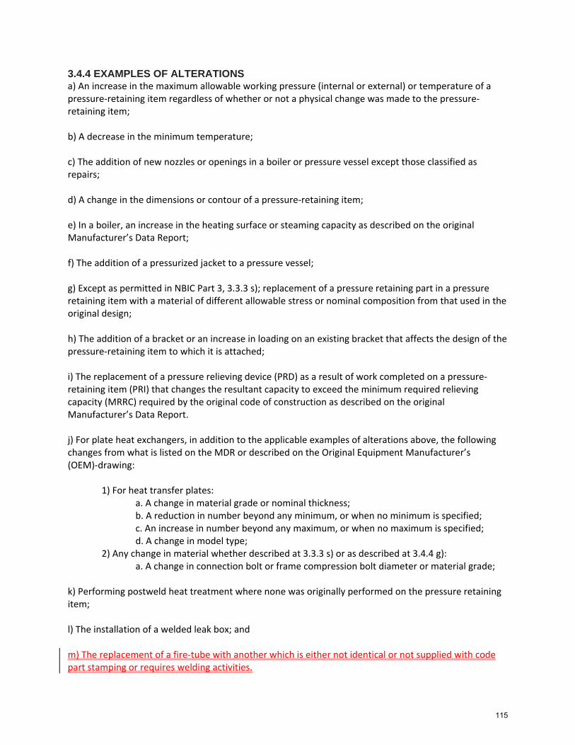
3.4.4 EXAMPLES OF ALTERATIONS a) An increase in the maximum allowable working pressure (internal or external) or temperature of a pressure‐retaining item regardless of whether or not a physical change was made to the pressure‐retaining item; b) A decrease in the minimum temperature; c) The addition of new nozzles or openings in a boiler or pressure vessel except those classified as repairs; d) A change in the dimensions or contour of a pressure‐retaining item; e) In a boiler, an increase in the heating surface or steaming capacity as described on the original Manufacturer’s Data Report; f) The addition of a pressurized jacket to a pressure vessel; g) Except as permitted in NBIC Part 3, 3.3.3 s); replacement of a pressure retaining part in a pressure retaining item with a material of different allowable stress or nominal composition from that used in the original design; h) The addition of a bracket or an increase in loading on an existing bracket that affects the design of the pressure‐retaining item to which it is attached; i) The replacement of a pressure relieving device (PRD) as a result of work completed on a pressure‐retaining item (PRI) that changes the resultant capacity to exceed the minimum required relieving capacity (MRRC) required by the original code of construction as described on the original Manufacturer’s Data Report. j) For plate heat exchangers, in addition to the applicable examples of alterations above, the following changes from what is listed on the MDR or described on the Original Equipment Manufacturer’s (OEM)‐drawing:
1) For heat transfer plates:
a. A change in material grade or nominal thickness; b. A reduction in number beyond any minimum, or when no minimum is specified; c. An increase in number beyond any maximum, or when no maximum is specified; d. A change in model type;
2) Any change in material whether described at 3.3.3 s) or as described at 3.4.4 g): a. A change in connection bolt or frame compression bolt diameter or material grade;
k) Performing postweld heat treatment where none was originally performed on the pressure retaining item; l) The installation of a welded leak box; and m) The replacement of a fire‐tube with another which is either not identical or not supplied with code part stamping or requires welding activities.
115
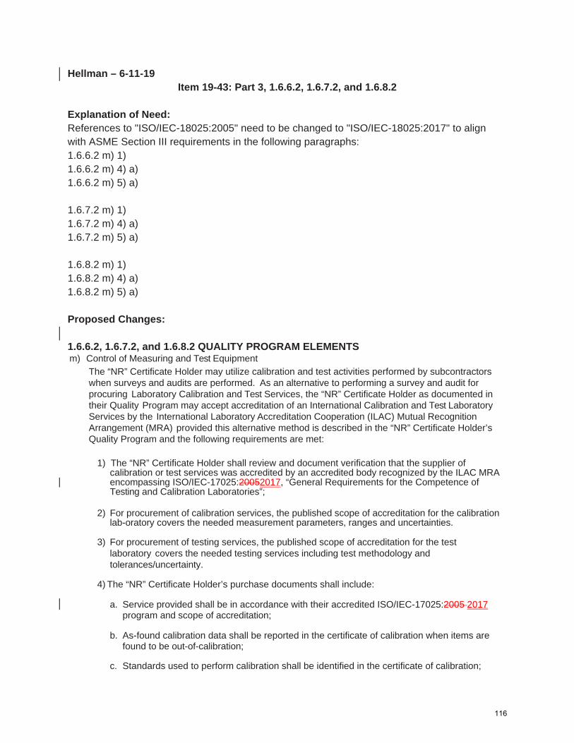
Hellman – 6-11-19 Item 19-43: Part 3, 1.6.6.2, 1.6.7.2, and 1.6.8.2
Explanation of Need: References to "ISO/IEC-18025:2005" need to be changed to "ISO/IEC-18025:2017" to align with ASME Section III requirements in the following paragraphs: 1.6.6.2 m) 1) 1.6.6.2 m) 4) a) 1.6.6.2 m) 5) a) 1.6.7.2 m) 1) 1.6.7.2 m) 4) a) 1.6.7.2 m) 5) a) 1.6.8.2 m) 1) 1.6.8.2 m) 4) a) 1.6.8.2 m) 5) a) Proposed Changes: 1.6.6.2, 1.6.7.2, and 1.6.8.2 QUALITY PROGRAM ELEMENTS m) Control of Measuring and Test Equipment
The “NR” Certificate Holder may utilize calibration and test activities performed by subcontractors when surveys and audits are performed. As an alternative to performing a survey and audit for procuring Laboratory Calibration and Test Services, the “NR” Certificate Holder as documented in their Quality Program may accept accreditation of an International Calibration and Test Laboratory Services by the International Laboratory Accreditation Cooperation (ILAC) Mutual Recognition Arrangement (MRA) provided this alternative method is described in the “NR” Certificate Holder’s Quality Program and the following requirements are met:
1) The “NR” Certificate Holder shall review and document verification that the supplier of
calibration or test services was accredited by an accredited body recognized by the ILAC MRA encompassing ISO/IEC-17025:20052017, “General Requirements for the Competence of Testing and Calibration Laboratories”;
2) For procurement of calibration services, the published scope of accreditation for the calibration
lab-oratory covers the needed measurement parameters, ranges and uncertainties. 3) For procurement of testing services, the published scope of accreditation for the test
laboratory covers the needed testing services including test methodology and tolerances/uncertainty.
4) The “NR” Certificate Holder’s purchase documents shall include:
a. Service provided shall be in accordance with their accredited ISO/IEC-17025:2005 2017 program and scope of accreditation;
b. As-found calibration data shall be reported in the certificate of calibration when items are found to be out-of-calibration;
c. Standards used to perform calibration shall be identified in the certificate of calibration;
116

d. Notification of any condition that adversely impacts the laboratories ability to maintain the scope of accreditation;
e. Any additional technical and/or quality requirements, as necessary, which may include
tolerances, accuracies, ranges, and standards;
f. Service suppliers shall not subcontract services to any other supplier.
5) The “NR” Certificate Holder shall upon receipt inspection, validate that the laboratory documentation certifies that:
a. Services provided by the laboratory has been performed in accordance with their ISO/IEC-17025:2005 2017 program and performed within their scope; and
b. Purchase order requirements have been met.
n) Handling, Storage and Shipping
117

Item 19‐50: Part 3, 3.3.4.3 e) 3) l)
Explanation of Need: There are a couple of typos in the paragraph that lead to the current wording not matching up with the rules of ASME PCC‐2 for External Weld Metal Buildup. Proposed Revision: l. For each repair, the maximum dimension (L, length along axis) compensated by a circular or oval
weld buildup shall not exceed the lesser of 1/4 the nominal outside diameter or of the component of or 8 in. (200 mm). The length of a rectangular patch is not limited;
118

Item 19-52 - Hellman – 6/25/19 PART 3, SECTION 4 REPAIRS AND ALTERATIONS — EXAMINATION AND TESTING 4.1 SCOPE This section provides requirements and guidelines for performing examinations and tests for repairs and alterations to pressure-retaining items. 4.2 NONDESTRUCTIVE EXAMINATION a) The nondestructive examination (NDE) requirements, including technique, extent of coverage,
procedures, personnel qualification, and acceptance criteria, shall be in accordance with the original code of construction for the pressure-retaining item. Weld repairs and alterations shall be subjected to the same nondestructive examination requirements as the original welds. Where this is not possible or practicable, alternative NDE methods acceptable to the Inspector and the Jurisdiction where the pressure-retaining item is installed, where required, may be used., provided that all other requirements of this section are met.
b) NDE personnel shall be qualified and certified in accordance with the requirements of the original
code of construction. When this is not possible or practicable, NDE personnel may be qualified and certified in accordance with their employer’s written practice. ASNT SNT-TC-1A, Recommended Practice Nondestructive Testing Personnel Qualification and Certification (2006 edition), or ANSI/ASNT CP-189, Standard for Qualification and Certification of Nondestructive Testing Personnel (2006 edition), shall be used as a guideline for employers to establish their written practice. Provisions for training, experience, qualification, and certification of NDE personnel shall be described in the “R” Certificate Holder’s written quality system.
119

NB19-53 6/25/19
Request for NBIC Part 3, Supplement 2 Revision
Robert V. Underwood The Hartford Steam Boiler Inspection & Insurance Company
Purpose
To address record retention requirements in Supplement 2.
Scope:
Revise S2.12 to refer to Part 3, 1.5.1(t) record retention requirements.
Background
S2.12 only states that job records “should” be retained by the owner. Paragraph 1.5.1(t) and Table 1.5.1 requires that all job records that substantiates the description of work on the applicable “R” Form be retained for five years. This revision will clarify record retention requirements in Supplement 2 and bring them to compliance with Part 3, Section 1.
Proposed Revision
See page 2 for proposed revision.
PROPOSED REVISION TO SUPPLEMENT 2, S2.12
S2.12 DOCUMENTATION Organizations performing repairs to historic boilers shall document the repair or alteration on Form R-1 or R-2, as applicable. Job records shall be retained in accordance with NBIC Part 3, 1.6.1(t). Additionally, pPermanent documentation detailing repairs or alterations should shall be retained by the owner in permanent boiler records such as an operator log book.
120