Embed Size (px)
Citation preview
,.
I
.
*Wb
.9
ARR h70. 3K10
47 ..-.
NATIONAL ADVISORY COMMITTEE FOR AERONAW
wul’rmll lm?olw
.0RK3NAUY ISSLJED.,, ,,November 1943 as
Advance Restricted Report 3K1O
FLIGHT TESTS OF THERMAL ICE -PREVENTION EQUIPIyIENT
ON A LOCKHEED 12A AIRPLANE
By Richard Scherrer
Ames Aeronautical LaboratoryMoffett Field, California
NAC~ ‘
.,WASHINGTON “
NACA WARTLME REPORTS are reprintsofpapersoriginallyissuedtoproviderapiddistributionofadvanceresearchresultstoan authorizedgroup”requiringthem forthewar effort.They were pre-viouslyheldunder a securitystatusbutare now unclassified.Some ofthesereportswere nottech-nicallyedited.Ml have been reproducedwithoutchangeinordertoexpeditegeneraldistribution.
A-49
—
3 11760136’4W ‘J .*.__. —
HAT IOHAL ADVISORY COI(MI!I?!I!EB
.,.. . . . . . . . .
...—
FOR MRONMJ!CICS
RBPOET . 1
. .. . .
IfLIGHT TESTS OF THEEMAL IOM.PUVEMT IOE. EQUFIP~ET ,“..
OH A“LOCKH14MD la AIRPLAME “ .“.-. . .~X RiOhaX~ Saherrer “ “ “. .
SUI04ARY’ “. .
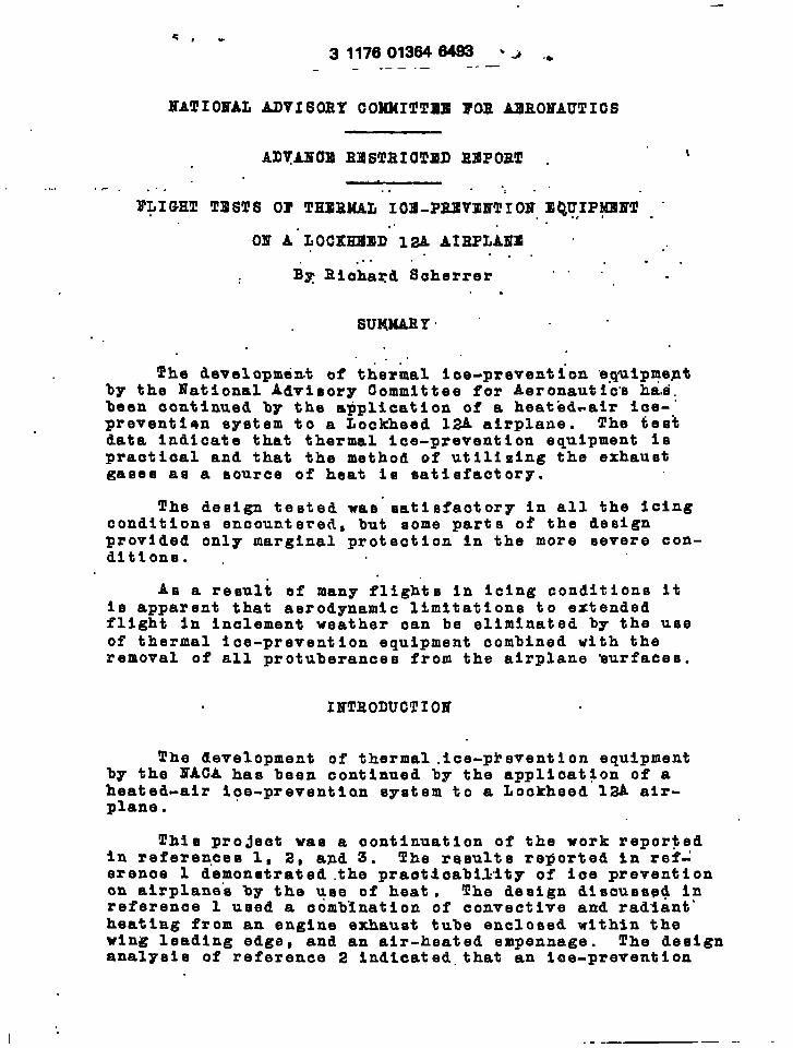
The developmdmt of t~er~al ice-prevention “e-quiprneptby the National Advieory Committee for Aeronautic’m haia.been continued by the a~plication of a heated-air ice-”prevention sygtem to a Lockheed la airplane. The tieebdata indicate that thermal ice-prevention equipment Ispraetioal and that the method of utilizing the exhaustgaBee aa a eource of heat ie aatiefactory.
The design tested wae”aatiefaotory in all the Icingconditions encountered, but some parts of the designprovided only marginal protection In the more eevere con-ditions. .
As+ a reeult ef many fligh”ta in icing conditions itie apparent that aerodynamic l%mttatlone to extendedflight 3n Inolement weather can be eliminated by the useof thermal ice-prevention equipment combined with theremoval of all protuberances from the airplane surfaces.
INTRODUCTION
The development of thermal .ice-pi’eventlon equipmentby the lTACAhas been continued by the application of aheated-air i?e-preventlan systiem to a Lockheed 12A air-plane.
This projeet was a continuation of the work reportedIn references 1, 2, and 3. The results reported in ref:erenae 1 demonstrated the praotdoability of ioe preventionon airplane”a by the use of heat, !Che deeign discusspd inreference 1 used a combination of convective and radiantsheating from an engine exhaust tube enclosed within thewing leading edge, and an air-heated empennage. The designanal~eis of reference 2 indicated. that an ice-prevention
1“ ..-— -.
.-
●{’
2
.,!=
‘. ~-. . ,: . . .
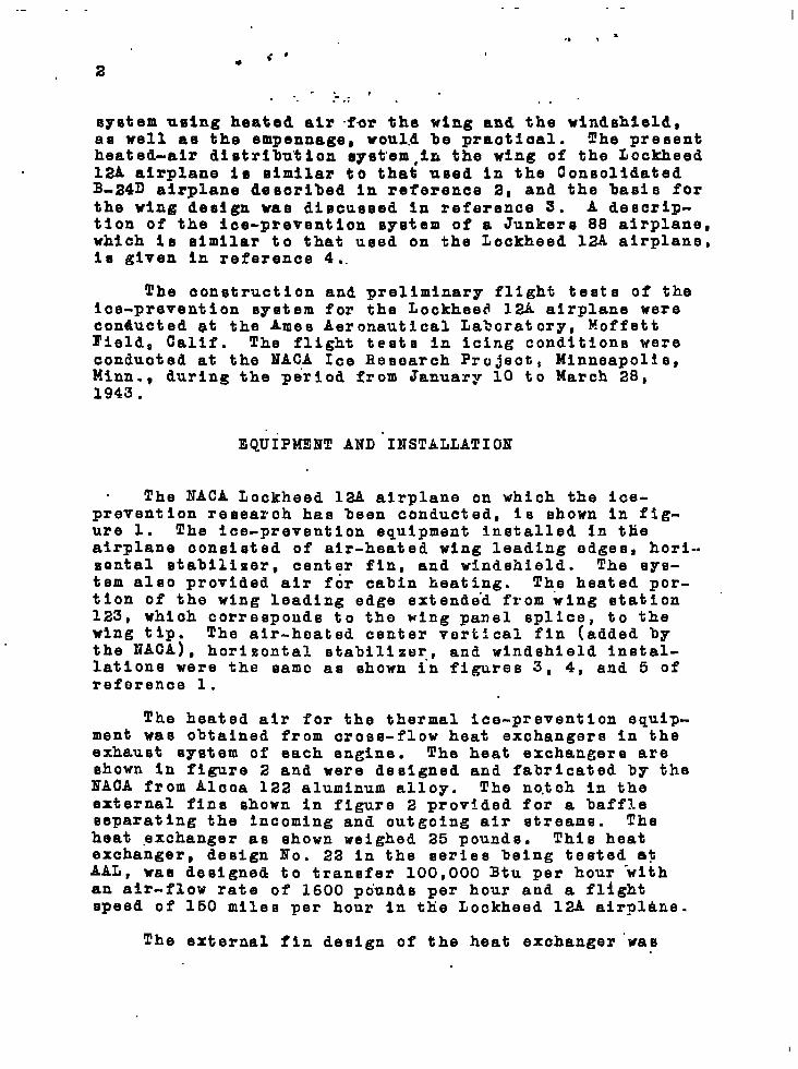
eyetem using heated air for the wing and the nlndmhleld,as well as the empennage, would be praatioal. The presentheated-air diutrlbu%ion system,ln the wing of the Lookheed12A airplane in eimilar to that used in the ConsolidatedB-24D airplane desoribed in reference 2, and the basis forthe wing de~ign wae diecueeed in reference 3. A deecrip-tlon of the ice-prevention system of a Junkers 88 airplane,which is similar to that used on the Lockheed 12A airplane,is given in reference 4..
The construction and preliminary flight tests of theice-prevention system for the Lockheed 12A airplane wereconducted at the Ames Aeronautical Lahcratory, MoffettField, CalIf. The flight tests in Icing conditions wereconducted at the NAC.A Ice Research Projects Minneapolis,Minn. , during the period from January 10 to March 28,1943.
EQUIPM319T AND .INSTALLATION
. The NACA Lockheed la airplane on which the ice-preventlon resear(sh has been oonducted, is shown in fig-ure 1. The ice-prevention equipment installed in tlieairplane oonsleted of air-heated wing leading edges, hori-.zontal stabilizer, center fin, and windshield. The sys-tem also provided air for cabin heating. The heated por-tion of the wing leading edge extende”d from wing station “123, which corresponds to the wing panel splice, to thewing tip. The alr-heated center vort:cal fin (added bythe NACA), horizontal stabilizer., and windshield instal-lations were the same as shown in figures 3, 4, and 5 ofreff3rence 1.
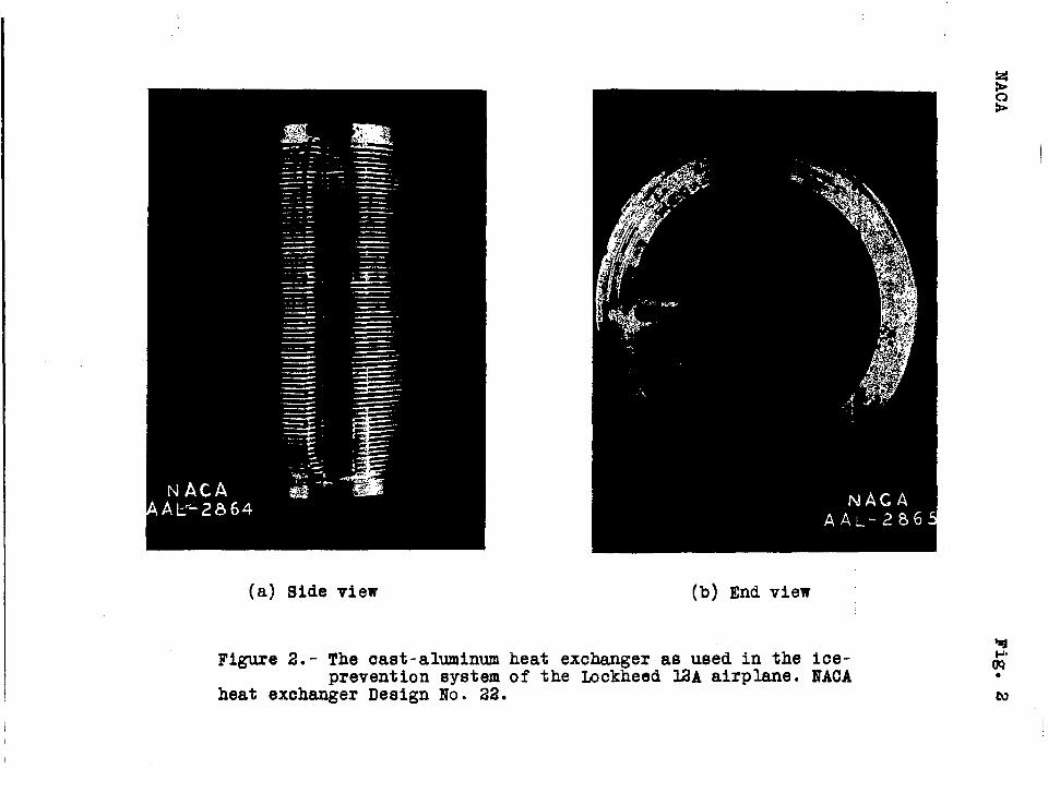
The heated air for the thermal ice-prevention equ3p-ment was obtained from cross-flow heat exchangers in theexhaust system of each engine. The heat exchangers areshown in figure 2 and were designed and fabricated by theI?ACA from Alcoa 122 aluminum alloy. The notch in theexternal fins shown in figure 2 provided for a baffleseparating the incoming and outgoing air streams. Theheat exchanger as shown weighed 25 pounds. This heatexchanger, design No. 22 in the series being tested a?AAL, was designed to transfer 100,OOO Btu per hour ‘withan air-flow rate of 1600 pounds per hour and a flightspeed of 150 miles per hour in the Lockheed 12A airplane.
The external fin design of the heat exchanger ”wae
● a,
“+●
. 3
based on refererice 5 and the interrial heat transfer wagcomput.ed.”by a method for gas-flow in narmm gape (refer- .enoe 6). . ., ;“’
., . .... ., . .The exhaumt-gae-to-air heat-exehanger aeeembliee were
eaoh Incorporated in two units, the oaet-aluminum heatexehanger and a double-tube he”at exchange-r. ““The east- “aluminum heat exehangere ~rovi~ad heated ‘air for the wingsand the empennage; while :the .doutile-tube heat exohangez%provided for oabln hestdng and .windeh.l’eldice’ prevention.”The heat=exchanger, aesembly. i.e...shownin figures 3(a) and3(b).. .?...”
J. .
,
. . . . . .
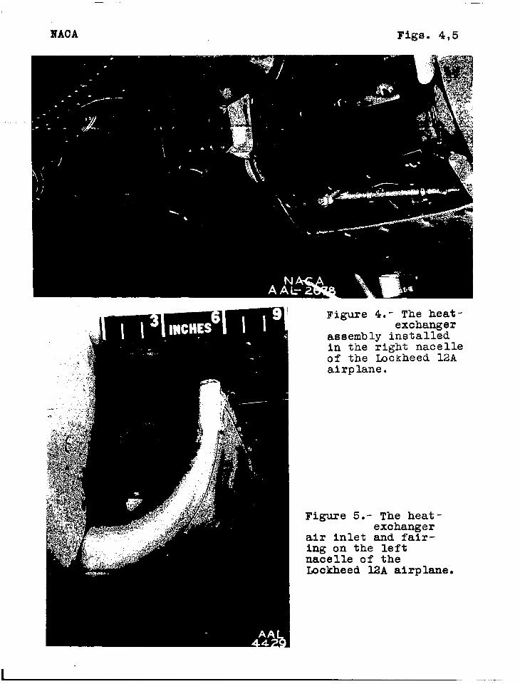
The air aircul”at.ion .t~rough the”~xchangerm and the airoutlete to the wing and empennage lead-ing edges. is shownIn figure~b). The exohamger assembly. is Bhowm mounted. in “the engine exhauet myetem in figure 4. ..The.alr inlet and “ :the com~lete installation epaloeed in the nacelle and “fairing are shown in figure 5.
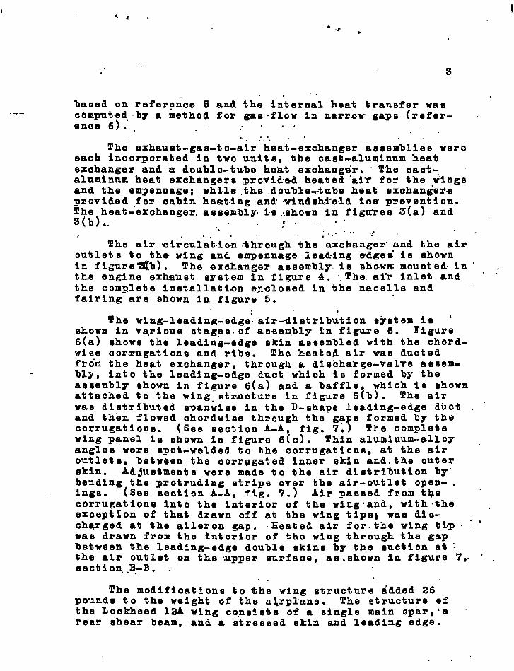
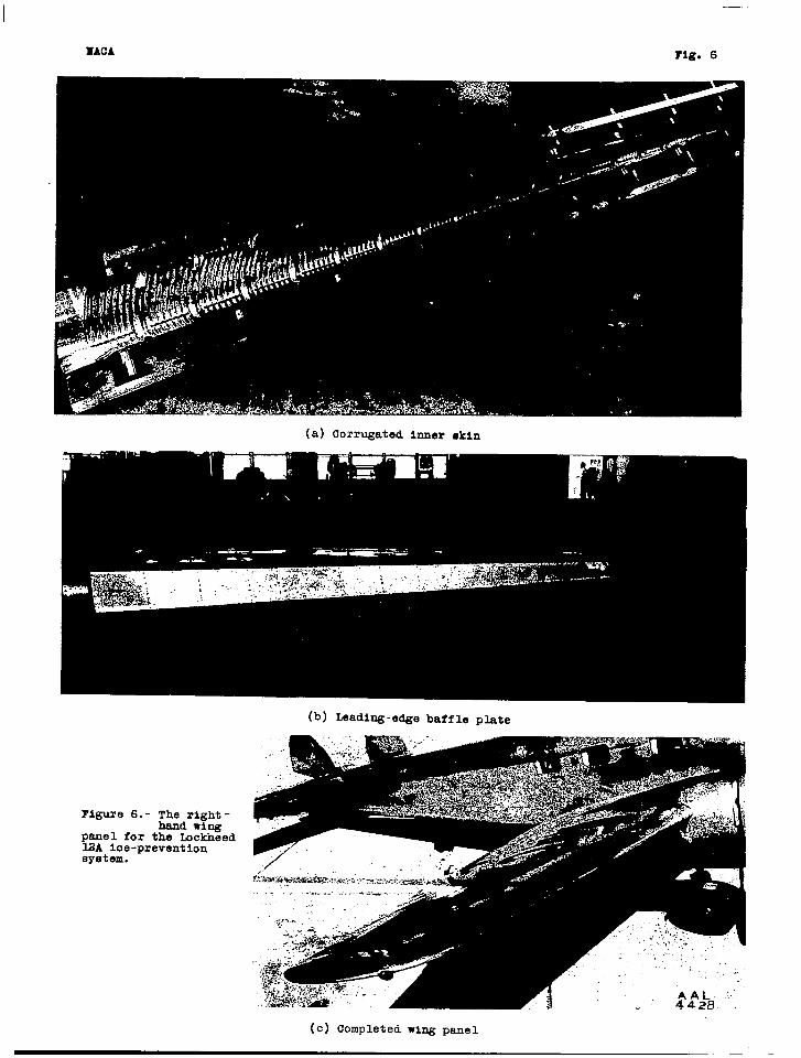
The Wing-leading-edge.. alr-distributlon eystem is ‘shown In va,rious etagea. of asaem.bly In #’igure 6. l’tgure6(a) ehowe the leadin~-edge skin assembled with the chord-wlee corrugations and ribs. The heated air wa~ ductedfrom the heat exchanger, through a discha”rge-valve assem-
% bly, Into the leading-edge duct. which is formed by theaesembly shown in figure 6(a) and a baffle
Iwhich is shown
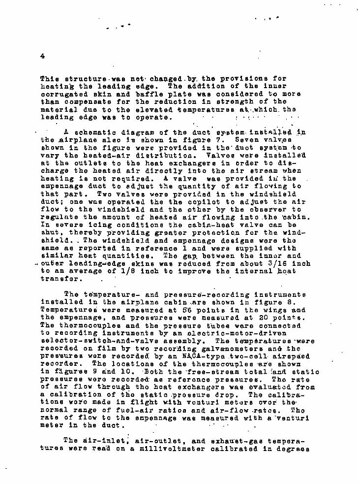
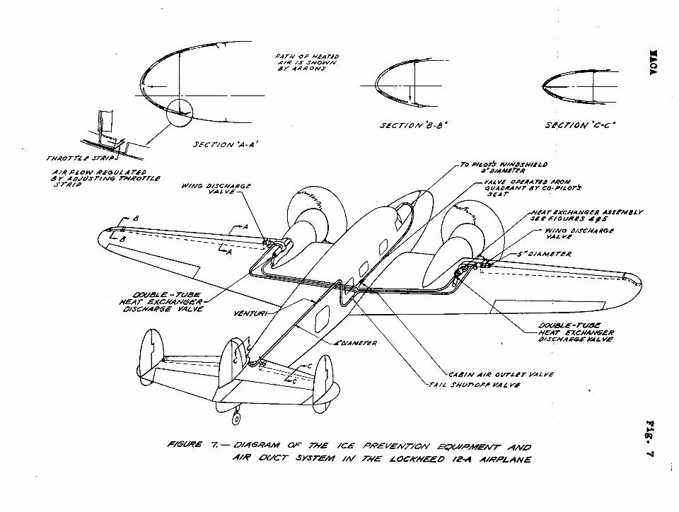
attached to the wing. str.ucture in figure 6 b). The airwas distributed spanwise in the D-shape leading-edge duct . “and then flowed chordwlse through the ga s formed by thecorrugation. (See section A-A, fig. 7;T The completewing panel is shown in figure 6(c). Thin aluminum-alloy .anglee were spot-welded tn the corrugations, at the airoutlete, between the corrugated inner ekin and.the outerskin. Ad~ustmente were made to the air distribution by”bending the protruding stripe over the air-outlet open- .inge. (See se~tion A-A, fig. 7.) Air paeeed from the “corrugations into the interior of the wingiandt with ”the .exception of that drawn off at the wing tipe~ wae dts- . .charged at the aileron gap. .Heated air for.the wing tSP “ .was drawn from the interior of the wing through the gapbetween the leading-edge double skins by the euution at :the air outlet on the ..upper surface, ae.shown in figure 7,. ‘ .section.B.-B. .
. .The modifications to the wing structure added 26
pounds to the weight of the a~rplane. The structure efthe Lockheed 12A wang co.nsiete of a s~ngle main epar,’a “rear ehear beam, and a stressed skin and leading edge.
#n-,%-.
4
This structure .wae net. cha~ged. by. the provisions forheating the leading edge. The addition of the inuercorrugated skin and baffle plate wae considered to morethan compensate for the reduction in strength of thematerial due to the elevated temperatures at,..whlch.thaleading edge was to operate. ,. . .:.f.”” .“”
..“ A schematic diagram of the duct’ system.insi~l.l”etl ~.nthe airplane also ia shown In figure 7. Seven valv$eshown in the figure were provided In the” duct syst.arntovary the heated-air distrlbutloa. Valves were Jnstalle.dat the outlets to the heat exchangers in order to dis-charge the heated air directly into the air stream whenheating is not required. A valve wae provided iu. the .empennage duct to ad Just the quantity of air flowing tothat part. TWO Valvee were provided in the windshieldduct ; one wa.e operated the the copilot to ad Just the airflow to the windshield and the gther by the observer toregulate the amount of heated air flowlng into the ‘csbln.In severe Icing conditions the cabin-heat valve can beshut , thereby providing grsater protection for the wind-shield. . The windshield and empennage designs were thesame as reported In reference 1 and were supplied withsimilar heat quantities. The gap, between the Inner and
..outier leading~edge skins was reduced from about 3/16 Inchto an average of 1/8 inch to improve the Internal hc.attransform . “
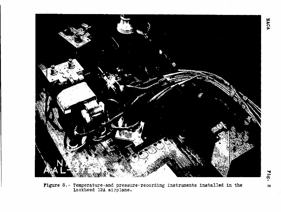
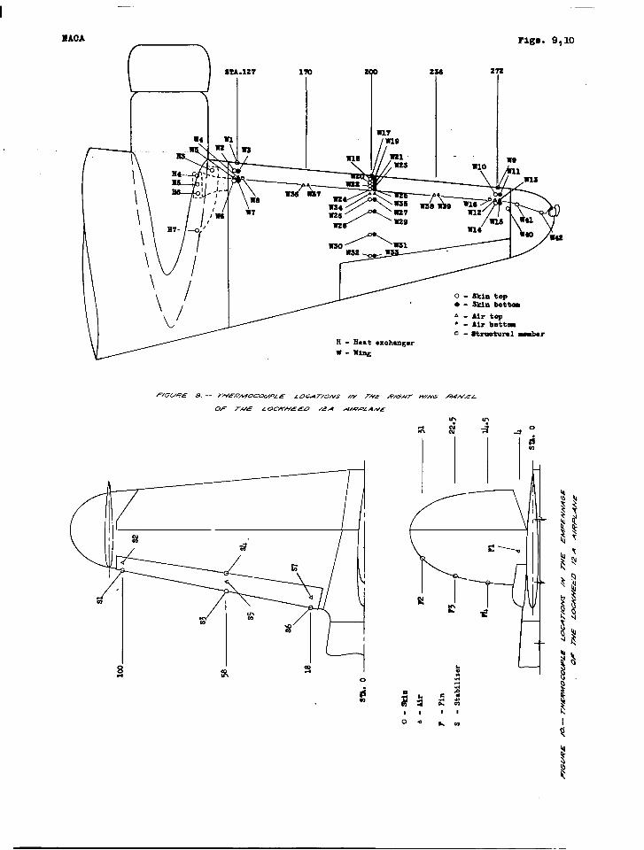
The te.mperature- and preseurd-recording instrumentsInstalled in the airplane cabin ..are shown in figure 8.Temperature were measured at 56 points in the wings andthe empennage, and pressures were measured at 20 points.The thermocouples and the pressure t“ube=eware connectedto recording instruments by an olectrlc-motor-drivenselector-ewitch-and-valve aesembly. The temp&ra.turos -werereoordod on film by two recor.lling galvanometers an& thepressures wore recorded by an HACA-typa .two-cell. airsp~edrecorder. The locations of the thermocouples .ar”eshownin figures 9 and 10. Both the “free-stream total {and staticpressures woro reoorde~ as reference pressures. Tho rateof air flow through tho heat exchangers was bvalu~tcd froma calibration of the etatic .prossure drop. The calibr&-tions woio made In flight with venturi meters ovoti the.normal range of fuel-air ratios and air-flow .ratcs. Thorate of flow to the empennage was measured with a-venturimeter in the duct. .. ..
The dir-inlet; air-outlet, and exhau.st-ga6 tempera-tures were rea”d on a mlllivoltmeter calibrated In degrees
5
Fahrenheit and shown on the observer’s ~nstrument panel ,in-figure “il.- The exhaust-gas thermocouples were” un-mhielded and no correction.~ were made for radiationeffeote.
Th~- service airspeed head on the airplane IS locatedon a macet extending down from the fuselage at a pointapproximately 2 feet aft of the nose. Difficnalty “waeexperienced with this installation in icing oondftlonsbecause ioe aocretione on the support mast affecte! the .etatie pressure at tho airspeed’ head. In order to. eltml-?ate this di”ffieulty, two statio-pressure Orifieea were.Installed in the surface of the rear p.brtion. of the fuse-lage to obtain a more copsi.stent and exact statio-pressurerneataurement un~er all oondltions.
TESTS AYD RESULTS I
The flight teste in natural icing condltione ‘were”planned with the cooperation of the U. S. Weather Bureauand the Northwest Airlines dispatch office. After flylng
.tinto the region of the icing conditions, a preliminarysurvey of the fertioal and horizontal extent of the Icingregion was made, recording ambient-air temperature, altl-tude, t~me, and observations’on the severity .of the iolngconditions. Thd flight was then cuntinued in the Icingcondition Belected.
. .
During the ~cj.ng fli~ts, records wer6 taken o“f the‘ te~peraturee and the preesures in the ioe=prevention sys-tem. Ehotographe and notes of Ice formations and meteoro-logical conditions that were encountered were ueid.ah a.“basic for changes.to the ice-prevention system during the:progress of the tests.
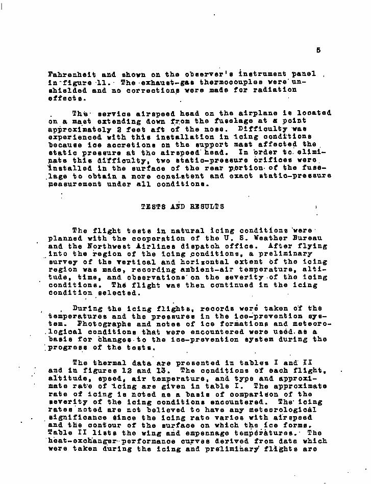
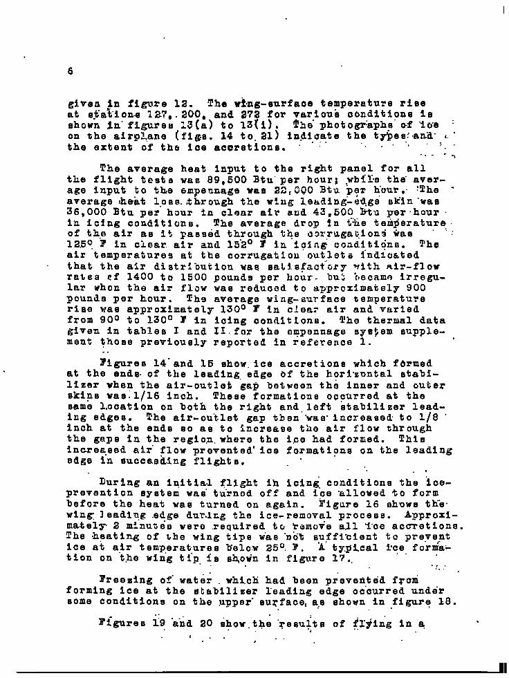
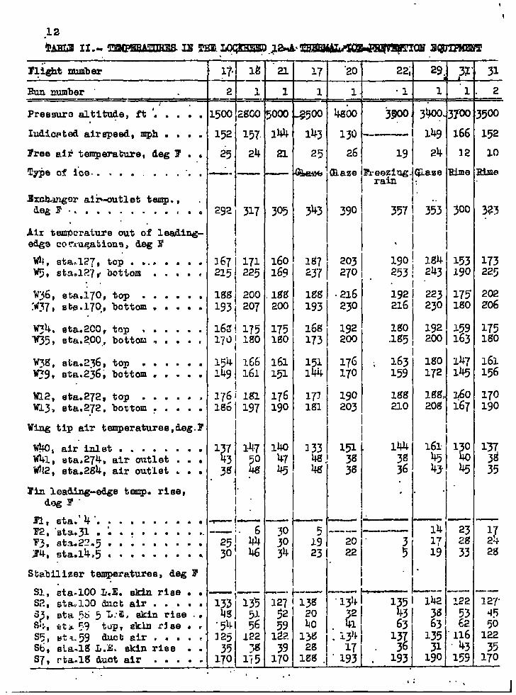
The thermal data are presented in tablss I and’ XI. .and in figures 12 and 19. The conditions of each flight, .al”titude, speed, air temperature, and type and approxi-mate rat’e of Icing are given In table I. The approximaterate of icing is noted as a basis of oompari$on of theseverity of the iolng conditions encountered. The” ioingrates noted are not believed to have any meteorologloalslgnifioance dinoe the ioing rate varies with ai”rspeed.and tlie oontiour of the surfaoe on which the ice forms.Table II lists the wing arid empennage tempdiktures.” The“hbat-exetian~r..performanae curves derived from data whichwere taken d“uring the icing and pre”limihary’ fl.lghts are
6
given in figure 12. The wi,ztg-surfaoe temperature riceat e$ationa i27, .200, and ~72 for vartoui conditions Imshown in-figure~ 13(a) to 13{i). The- photogr:aphp”of ‘iue :on the airp%.ane (figs. 14 to. 21) In.diaate the typem:.an.d-i..the extent of the ice accretions. . .‘“ “. J “ .’ . ‘. “
... --l
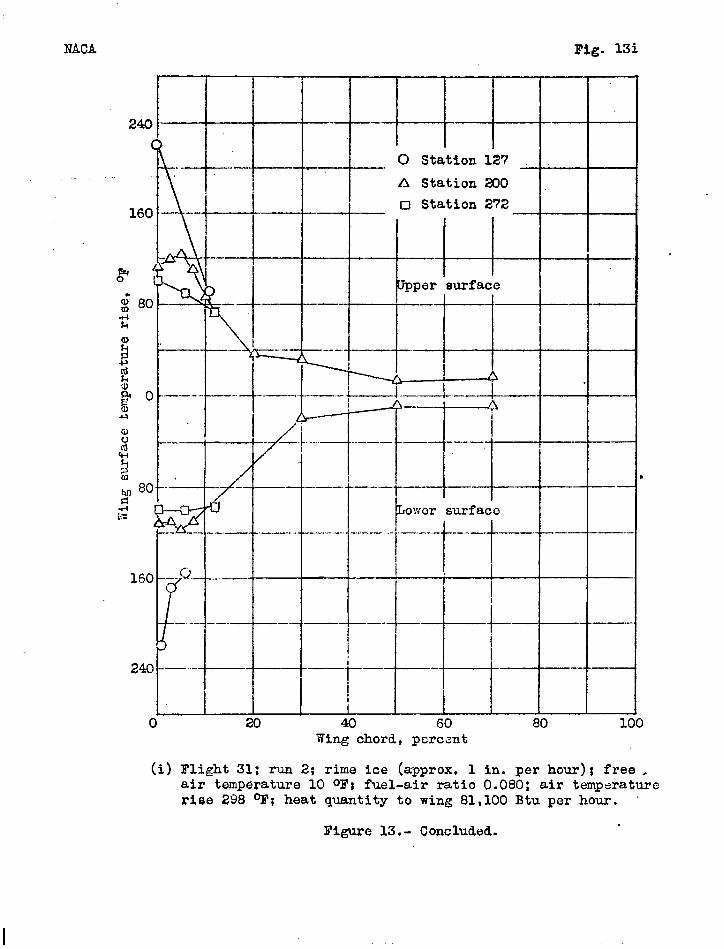
The average heat input to the right panel for allthe flight teBts was 89,500 Btu.per hour; ..wbf~nethe. aver-.age input to the em~eunage was 22~GQ0 Btu pgr hour,. ~The -average :heat loss. khrough the w:.ng leading”-edgs’ sk’inwas36,000 Btu per” hour In clear air aud 43,500 btu per”hour .in icing conditions. The average drop Sn t%e temperature.of the air as it paBsed through %+e oarruga~.ion$ tiaa ‘ ..:1250 F in clear. atr and 15”2° F in lcfn~ ccaditl~ns. Theair temperatures at the corrugation outlet= ~ndlcatedthat the air distrihuij.on wag sa~ls~act”~ry with air-flowrates rf 1400 to 1500 pounds per hour. bui ~~ecamn irregu-lar when the air fiow was reduced to approximately 900pouniie per hour. Thg average wing-surface temperaturerlee waO approximately 130° F in clea= air an~ variedfrom 900 to 130° F in icing oonditlons. l!he thermal datagiven in tables I and 11.for the empennage sys$em supple-ment those previously reported in reference ~.
.
..~i~res 14-and 15 chow.ice accretions which fermed
at the ends. of the leading. edge bf the horizontal stabi-lizer when the air-out~et gap between the inner and outerskips was:l/16 inch. These formations o~curred at thesame Location on both the right and. left stabilizer lead-ing edges. The air-outlet gap then “waB.increased to 1/8 .inch at the ends so as to increase the air flow throughthe gaps in the regio.n,where the ice had formed. Thieincreased air” flow prevented’ Ice formations on the leadingedge in succasdlng flights,
. .. . .During an Inltia.1 flight ih icing conditions the ~ce-
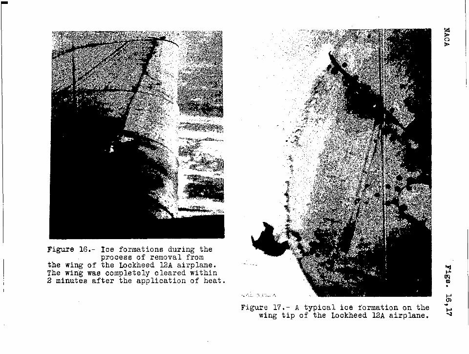
prevention system waB” t~rnod off and ice allowed ‘to formbefore the heat was turned on again. Figure 16 shows th-e.wing. leadi~g edge dur.i~g the ice-removal process. Approxi-ma.tel~ 2 minuteo were required to kamove all Y“ce accretions.The .hpatin.g of the wing tips w“as .~ot s,u$fibient to preyefntIce at alr temperatures 15elo.w25°. F. A typzcal tce fornra-tion on the wing tip, is shown in figure 17..
. .
-,...”I’reezing of.water . which had been prevedtdd f~orn
forming ice at the stabilizer leadin~ edge oc”curred undersome conditions on the upper- su~facet a:s ehown in figure 18.
1.. . ..
7
The heat -exphang~r. per formanod was in.“go-od“~reement. ...
<with the. design yalus s”,as” show.n””in figure” .12. :The he+t .exchanger were inepe”o”ted sbv”era~ times during the flightoperations at the Ice Researoh Projact “1’nor~er ‘to deter-mine”.‘if there had been any deterioration of the aluminumaaObinge. The first inspection indio~t!ed that””tihere”hadbeen dome Groslon and melting of the tips of the internalf$he by the exhaust ..gases; Latir lnspeet~one, after morethan 50 hours of aerviee; .shoyq& that there had beenlittle or no additlonaz tietertoration of the inte-rnal ..””fins. ””.,” .. ..
.. .“, ,,,}-,.. :. .-. . ,‘.:D’lSCU&IO~ . .“,””‘.! .r+ . ::..:“ ~..
;.’ .“.?- ...... .. . ...,,. ,.. . . .. .
.’.’Thereeulte obtained wjlth the thermal ioeapre~entlonequi>meat ~nstalled .on,~the Lookheed 124 airplane .~~e..l?.agreement wtt,h those re~or,ted in reference 1 and Wl$l.!t .testg:,of:moqe reoent inetallatlone in other alrplaaas ...:.yo difficulty was experienced with the operati On..O&the:.
‘ ‘th6rmd1’1@e-pr event ion equipment and the flight tests.kere eendug~ed safely in all the condltlone .enonunkered.
....” .. ...,.. .... ..J. ....:.. ~. ‘The. heat .smhpplied to the wing panels was S.p~OX~-”..%,
mat”ely 2000 Btu per hour per square foot in dry. alr and. ”2600 Btu per hour per equare foot in Icing oond-itd~ne..;#In’ teht.d tith. ap X&24F airplane, approximately 40,000
‘~B%u p~r. hou!r.ware ‘tran~sfe~red through 45 aquare,f~bt ofmirf’ffo.e“area w~.th.an alr flow of 1600 pounde per ‘hour In
‘“teing conditions; while in the tests with the Lockheed 124
a“irplane 43 S.500 Btu per hour...yere.+tr.aqs$err~~..thro.ugh..16..6“square ;feet wtth 1.20.0.pohnd.s.per ~hpur of air .iti.simi-lar “oondit ions. .Mven wl.th the large heat input, the wing
.did not ha~a a ,o.omparabl~ high ~sverqge eurfa~e tOmp,~ra-ture. !l!heav~~age w$ng-crurfaoe” temgqratuce rlae,,raoordedin the ‘XB=24F sti.rplane test s,-was LOO” F ~n ~lear air and80° to’ ~06° F In i.s~ng o~ndttiioae: while the”. terngeratureefor the Lookheed 12A airplane were 130° F and 90 .to130° Y, reupeotively, with almoet three timee the unitheat input. “, “
The relatively l~rge’heat quantity transferred, per““unit area, to the wing ekin. of the Lockheed 12A. airplanewas due to the large mae~ ,flow through the oorrugationewith.consequent high lnternql heat -transfer ooefficlents.The wing-surface temperature did”not Increaee in the .eameratio ae the unit heat quantities transferred to-the ekin,probably because the external heat txanefer was greater“than on other deelgng.. .
6. Phe. boundary-la~er .characterieticm of’ the alrfo~%sectione go~ern the rate of ext~rnal. heat transfer. “ The
.IUCA 230.series sections used Oa the Lockheed 12A airplanenormally wculd.have lass chordwise extent of the~laminar
“boundary layer than the Davie. eect.ione uqed on the XB-24~airplane. The earlyonset of turbulent. flow,would tendto-inoreaae th~ external heat tranefery The incrpaOe inexternal heat transfer could have been caueed aleo.bypremature transition due to surface Irregularitlee thatwere apparent.
The faot that moro heat per unit area was necessaryto malntaln the wing surfaco at temperature only slightlyabove those- noted In the XBk24F, teats indicate that theu~e “of a fixed quantity” of ~eat. per .unlt area protectedmay have definite limitations ae a design criterion~,
. . .“A comparison Of the heat q~a.ntit~es and ekin tempera-
ture of the wing and empennage ~ndlcates that a greaterportion of the total ~utput fro% the heat exchangers couldhave been directed to the empennage and would have Improvedthe performance of these parts.
, . .The importance ~of having ap airplane t@a~ is.to-be
flown in inclement wea,ther ae~odynamically Clean cannot beoverstresned. It has.~een no-ted during many flights Inicing conditions that i.oe.wi”ll form on any object extendingfrom the eurface..of the ai-rpleme. Pigure -21 chows emallice aocretlons on the heads of 3/32-inch-diameter brazier-
. .
— .—.
.
. . 9
head rivets. Other objects on the Lookheed 1+ airplanewhich” normally aolleote”d ioe” were the radio antpnnas and.--...“=htenna”masts, Pitot-static head-maet, D-1’;loop. housings,door handles, cabin cold=air’”ecoopg, ta’il wheel, &andnavigation lights. Iee accretions.on these and- otherprotuberances uausb ‘large Iopdb and aerodynamic .disturb--ancek. “m “ ..1 “. .,
.. ....:... .., .>. .:,.“...
CONCLUSIONS .., “..,. .. “f. . . .. . ,., .“
1. Ths thermal ice-prevention” equipment in theLockheed. 12A airplane WBS satisfactory in all the icingconditlone encountered kpd con”firmed”tha practicabilityof he”ated-alr systems using the exhau”et.gaeek aa a sourceof heat. 1.
2. Aerodynan@c limitations to extended flight In “lclng conditions “can be eliminated by the use of thermalice-prevention equipment combined with the eliminationof all protuberances from the. surfaces of the airplane. -
Amee Aeronautical Laboratory,Hatlonal Advisory Committee for heronautio6,
Iloffett Field, Calif.
- - .——— .—— —. .—— — —
1. I
10
RFlF19RJllTcEls . “
1. Rodert, Lewis A., Clousing, Lawrenco A., and McAvoy,William H.:” Reoent Tlight Research on Ico Provo n-tion. .NACA A. R.R., Jan. 1942,
2. Jones, Alun R., and Rodert, Lewis A.: Development ofThermal Ico-Provontion. Equipment for the 3-24D Air-plane. NACAA.C.R., Feb. 1943. (Classificationchanged to ltRostrictadn Aug. 1943.)
3. Rodert, Lewi3 A.; and Jackson, Richard: PreliminaryInvestigation and Design of an Air-Ilaatod Wing forLockheed 12A Airplane. .N&CA A.R,R., April 1942.
4. Rodort, Lewis A., and Jackson, Eichard: A Ileacriptionof tho Ju 88 Airplane Antz-Icing Equipment. 2UChR.B., Sept. 194&?. : “ “
5. Biormann. Arnold 2,, and El19ibrock, Herman H., Jr.:The Design of Fins for Air-Coolod Cylinders. Rep.Eo . 726, NACA, 1941.
6. McAdame, William H.: Heat Trapsmleslon. McGraw-HillBook Co., Inc., 1942.
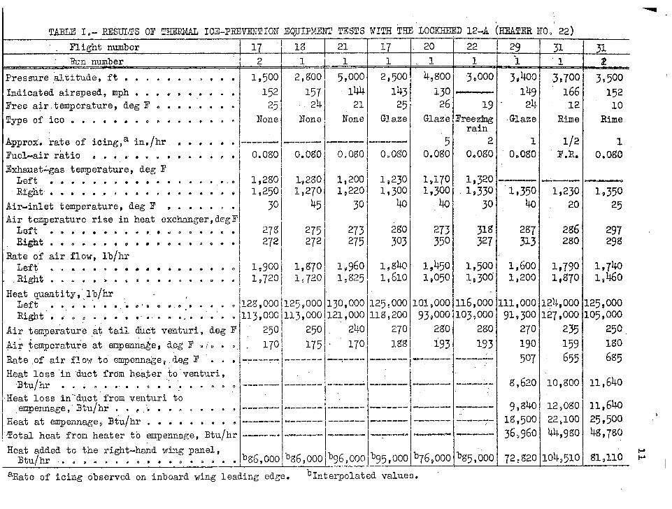
TABLIZ1.- RESULTS OF THEEMW ICE-?RWXNTIOITEQUIPMEW TESTS WITH T-W IJOCKIEED12-A (HEATZRNO.,22)
l?lightnqmber 17 “~
Pressure,al.titude,ft . . . . . . . .>. . .i 1,500indicatedairspeed,mph . . . . . . . . . . 152Free air.temperature,degl? . . . . . . . . 25!lypeofice. . . , . . . , . . . . . . . . None
Approx.rate of icing,ain,/hr, , . . . . . ----—Fuel-airratio . . ... . . . . . . . , , .I 0.0L30Exhaust~gas teqerature, deg F 1
Left . . . . . . . . . . . . . . . . . . 1,2s01
R~ght. . . . . .. .. . . . . . . . . . . e 1,250~Air-inlettemperature,deg)? , . . . . , . 30 ,Air temperaturerise in heat exchonger,degTLoft ● * . ● . . . ● ., ● * . 0 . . . . 27’sRight. ● o ● . ., 0 0. e e“ ● .$00 ● 272
Rate of airflow, lh/hrLeft , . . . . . . . . . . . . . . . . .I 1,900.Right. . . . . . . ... . . . . . . . . ,1 1,720
Heat quantity,’.,lb/hr - ,Left . . . . . . ..;.o.a OM.. . . . . ~ 12.8s000’Right’. . . . . . . . ... . .,’.,”.”.. 11.3,000
Air temperatureat tail duct venturi,deg 1? 250,.
+lirtemperatureat empenna~ejLeg T MY. . $. 170Rate.of air flow to empenna~e~,degF “. . . .,--------
Heat loss”induct from heater to”venturi,Btu/hr . . . . . ... . . . .:. . . . . ~ --------
Heat loss in-”duct”fromventuri to,empennage,”Btu/hr. , ‘P,* ● ● ,,* . ● ~ , ---—--
Heat at empewnage$Btu/hr . . . . . . . . _ ..--------
Total heat fron heater to empennage,Btu/hr -------
Heat added to the right-handwing panel,Btu/hr . . ,. . . . . . . . . .. 0 . . . bW,ooo
la1
2,goo1572$
None
—---—
o.o~o
l,2go1,270,
45
275272
1,s701,720
125,000113,000
250175
-------
,“----.--
--------------——-...
‘%6,000——
144 143 i3021 25 26
None Gla,ze Glaze1
I 5----—- --------
0.080 0.0s0 O.ogo
1,20011,230 l,i701,220 1,300, 1,300
30~ 40 ,40
273IZgo‘.
273275\ 303 350
Iiy960’lpml 1,450
1,610 1,0501’g25i.
130,000125,000‘101,OOO121,00011~,200 93,000
240 270] Mo
170!I
]-m i ig3--=---- ------- !—------_---_A ..,----- — ----
,.
I-------- !—------------
------+-----+ ------..-.---...-1--.-.1---
lb 1b96900CV95,000b76,000
22
1=
“3,000
19Freez3ngrain
2
00080
1,3201,330
30
318327
ij5001g3oo-
116,000l.oj,ooo
280193
-----—
-------
—-------------------
%S ,000
29
i_
3,40014921L
Glaze
1Oaogo
1,35040
2f3~313
1,6001,200
11,00091,300
270190507
s,620
9,~40lg,boo36>960
~2,a20
31~’,1
3,70016612
Rime
1/2I?.R.
A—.1,230
20
286280
11790l$a70
L24$oooL27,000
235159
655
10,8’00
12,0go22,10044,9~o
1043510
3i
3$50015210
Rime
10,Ow
-—
1,35025
l,7~+o1,460
L25,000L05,000
250lgo6g5
11,640
n,64025,500 ‘4g,760
bInterpolatedvalues.aRate of icing observedon inboardwing leading cdge~
Run number “ .. ~-
Pre09ure eltit@e, ft ‘.. . . .
Iudicated airspeed, mph . . . .
Free aititemperature, deg T . .
l!~eofl”ce .. . . . . .. m”. .
lxckmg~r aiiwutlet tamp., .degl’. < . . . . . . . . ..~
Alr tem&ature out ok leading-edg9 conuqabions, deg E
W4, Stahl??, top . ... . . . .*, stz.127~ bottom . . . . ,
. .
wy6, sta.170,top . . ● . . ,:437,stp.17C),bottom. . . . .
q4. stCh2co,top * ● . . . ●
~5 , Bt&.~oo,bottom. . . . r
W~8,sta.2~6, top . . . . . .~9, eSa.236;bottom. . . . .
W12,Ota.272, top . . . . . ,W13,sta.272,bottom~ . . . .
Wingtip air temperatures,d.eg.F
@0, airinlt3t m.......W41, ata.2T4, air outlet . . .W42, eta.2g4, air outlet . . ●
I% leading-edge temp. rise,deg F”
El,6ta.’ 4 .. . . . . . . . . .F2, msta.31m;.:.... .*.F3, st.392?.5● ● . . . . . . ●
T4, sta.14,5.9 . . ..m . .
Stabilizertemperatures,degB.
S1.,sta.100IJ.E.skinrise . tS2, ~ta,.120duct air . . . . .s~~ sta ~S 5 TJ;ZJ skinrise..(%;,~~~~q tq, skinr~ee. .S5,Ht%59 duotairm. ,.CS6,et.a.lgL.E.skin rise . .S7, Fta.lgdud air . . . . .
11.1 1~
7—.
2 .’&
G.—..
152 157.
25 2k
—. —
29z 317
1I
1671 1712151 225
lgg~ 2G0193 207
I16G! 175171y MO
154‘ 166J.49 161
1176i lg~186 197
II137 14.7
431 ()@3g ,
it .
/“~ ~—.—1. 6
251 ~}30’ 46
—11{; ‘T;;
“541 5g
L
125 12235 y?
170 1;5—.
1 n–i-m
w 143I 13”i-–––21
I25 26
I19
u305, 343 390I 357
160169
lm3200
175MO
161Ujl
176190
14047&
I1$7 203237 270
M8193
216230
16g’ 192173 200
151144
176170
173i 190Ml 203
I
.
190253
192216
lgo.1135
: 163159
ltw
ao
}1.—— l—
5 ‘----- +—-;19 I 20 “231 22 5
II
29
1
3?00
14’$1
24
~am
353
186243
223230
192200
Mo172
lIW20&3
161g
M1719
—--w?
31L
1
166
12
lime
joo
i~J190
175lgo
159163
~47145
360167
13040%
—23m33
.—1225362
11643
159
2
5500
152
10
Hme
323
173225
202206
175lgo
161156
170190
137yl35
17242g
-—127.475012235
170..-, . .
a: . . . I
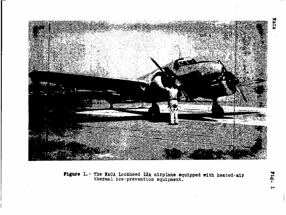
~igtaro 1.- The NACA Lockheed MA airplane equipped with heated-airthermal ice-prevention equipment: ‘- g
!I
I
(a) Side view (b) End view
Figure 2.- The cast-aluminum heat exchanger as used in the ice-prevention system of the bckheed 12A airplane. IVACA
heat exchanger Design No. 22.
I
I
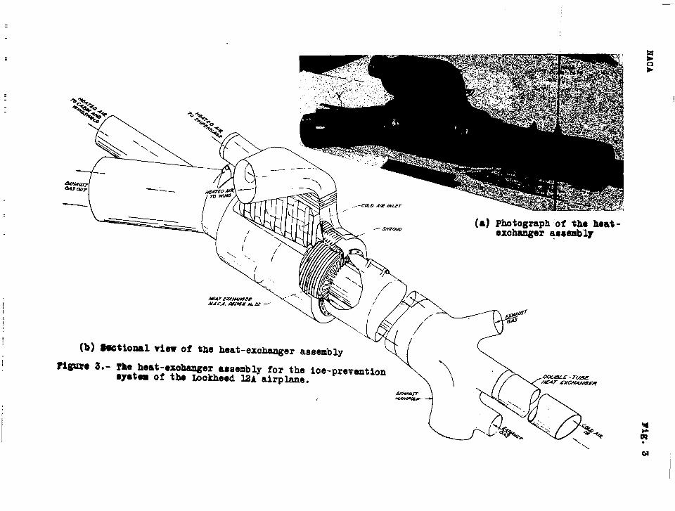
(a) Photographof tho heat-#efn/n .-er assembv
riguro 3.-
~ 4“i!si!ii!The heat-exe~er atsembly for the loo-prevention●yetem of the Lookheed 12A airplane.
x.\ % w“++,.
\, E.\
cd
I
—
HACA Figs. 4,5
Figure 4.- The heat-exchanger
assembly installedin the right nacelleof the Lockheed 12Aairplane.
Figure 5.- The heat-exchanger
air inlet and fair-ing on the leftnacelle of theLockheed 12A airplane.
1
HACA Fig. 6
(a)(corrugatedinner ●kin
(b) Leading-exe baffle plate
Figure 6.- The right-hand wing
panel for the Iockheed12A Ioe-preventioneyatern.
(c) Completedwing panel
/--.4 \/
P---------
sz-c7-/oN 3-8“ s#cno/v‘c-c“
“Wmb’z47iifl/-7 //’I L
‘3 “D/A Af87..U
---- _____ ---- ____
F/GU%5 z — z7/4GRA/1# W 7iiE /CE
AIR /70’c7-Sysrziw /N
.
Prevention Ei.A=2wEz/T AND
7iiE LOC@HEED /24 A/~PLwvE
.
Figure 8.- Temperature-and pressure-recording instruments installed in the a)Lockheed 12A airplane. I
HACA Fign.9,10
HST. ,127 1
1’:wlT
we
o - Skin top● - sumbotkh - Air top● - Air bettm❑ - *_*ml -=
H - Heat ●xoh~gmr
w -wing
272
F/Gu,eE s. — Z%57MOC-XZ E L OCA nON.s
OF THE L OCKH’EO /2A
I
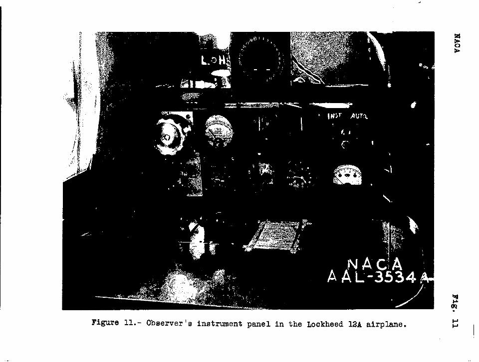
Figure 11. - Observer’s instrument panel in the Lockheed 12A airplane.
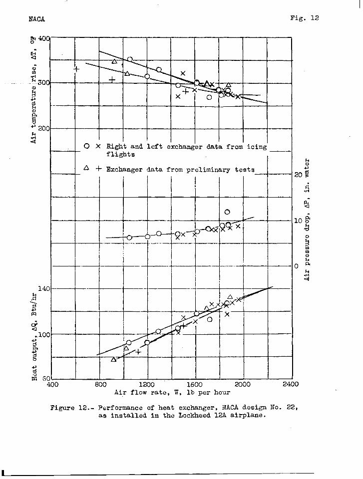
Fig. 12
-+
O X Right and leftflights
I A + Exchanger data
exchanger data from”icing’—..
from preliminary testsL
hal
201
.
400 800 1200 1600 2000 24Air flow rate, W, lb per hour
o
10
Figure 12.- Performanco of heat exchanger, itACAdesign No. 22,as installed in the Lockheed KM airplane.
—-
lTACA l?ig.13a
2
0 Station 127 ,
_A Station 20CI ~‘—.
T.
t
.—. —
•lStation 272
- ----’f:j-+:--~----’”
-*-< –--..-~-.-+----+ – --
,.++.-.L+T–-cb-=L=4-/-
ILowsr surface !
I
I
o 20 40 60 80 100Wing chord, percent
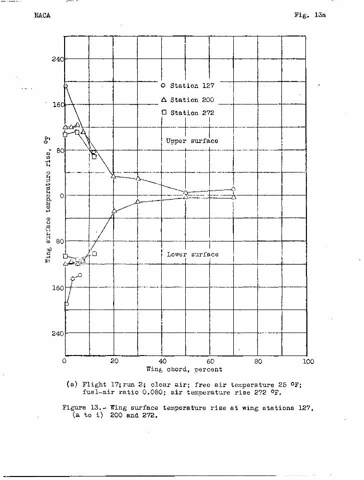
(a) Flight 1?; run 2; clear air; free air temperature 25 ol’;
fuel-air ratio 0.080; air temperature rise 2’?2 OF.
Fijzjure13. - Wing surface temperature rise at wing stations 127,(a to i) 200 and272.
NACA Fig. 13b
2
1
.
!40“ — .—.
I It-)0 Station 127
A Station 200
,60 .0 Station 272
qfi.,
“4
80 ~..!:3
b\..\~—+
t
o “ I—.
i ‘$
I I
Lower surfaceI
80 1 II I
o 20 40 60 80 100Wing chord, percent
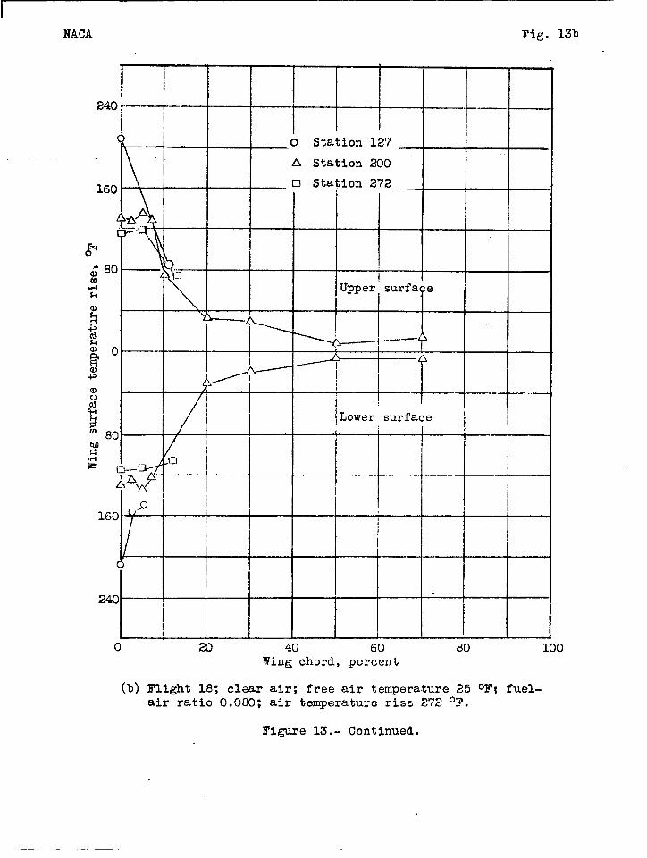
(b) II’light18; clear air; free air temperature 25 oF; fuel-
air ratio 0.080: air temperature rise 272 ‘F.
Figure 13.- Contj.nued.
I240 - ‘
() C Station 127
A Station 200
n Station 272160-
\
1-\
g ‘4.I
80 9.~
o-ma\
Upper surface.I-l& I
gcd& o&2al;
5a8
-y Lower surface
!$
16C.
()“
24C
\
o 20 40 60 80Wing chord, percent
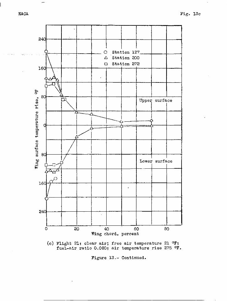
(c) Flight 21; clear air; free air temperature 21 ‘F;fuel-air ratio 0,080; air temperature rise 275 oF.
Figure 13.- Continued.
NAOA Fig. 13d.
240
160
o
.!+E
160
240
I
O Station 127
A Station 200
CI Station 272
Upper surface
Y
k-,U
‘~~-y—
1 ~
-..—
/’A
: + -
r]
-- —
Lower surface-———..— .- .—
&~o/-- — _—
—----‘– ------f____
__
20 40 60 80 100Wing chord, percent
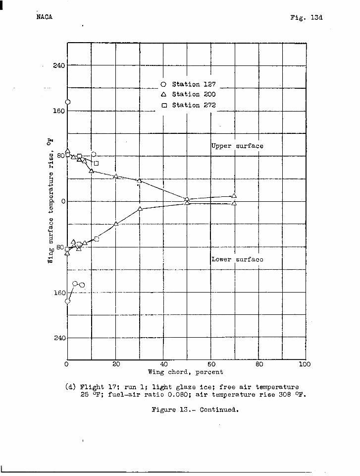
(d) Flight 17; run 1; light glaze ice; free air temperature25 ‘F; fuel-air ratio 0.080; air temperature rise 308 oF.
Figure 13.- Continued.
IfAOA I?ig. 130
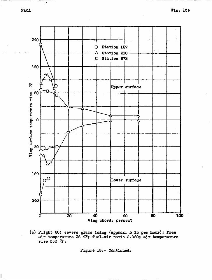
(e)Fli@t 20;severeglaze icing (a-ox. 5 lb per hour): freeair temperature 26 oF; fuel-air ratio 0.080; air temperaturerise 350 OF.
Figure13.. Continued.
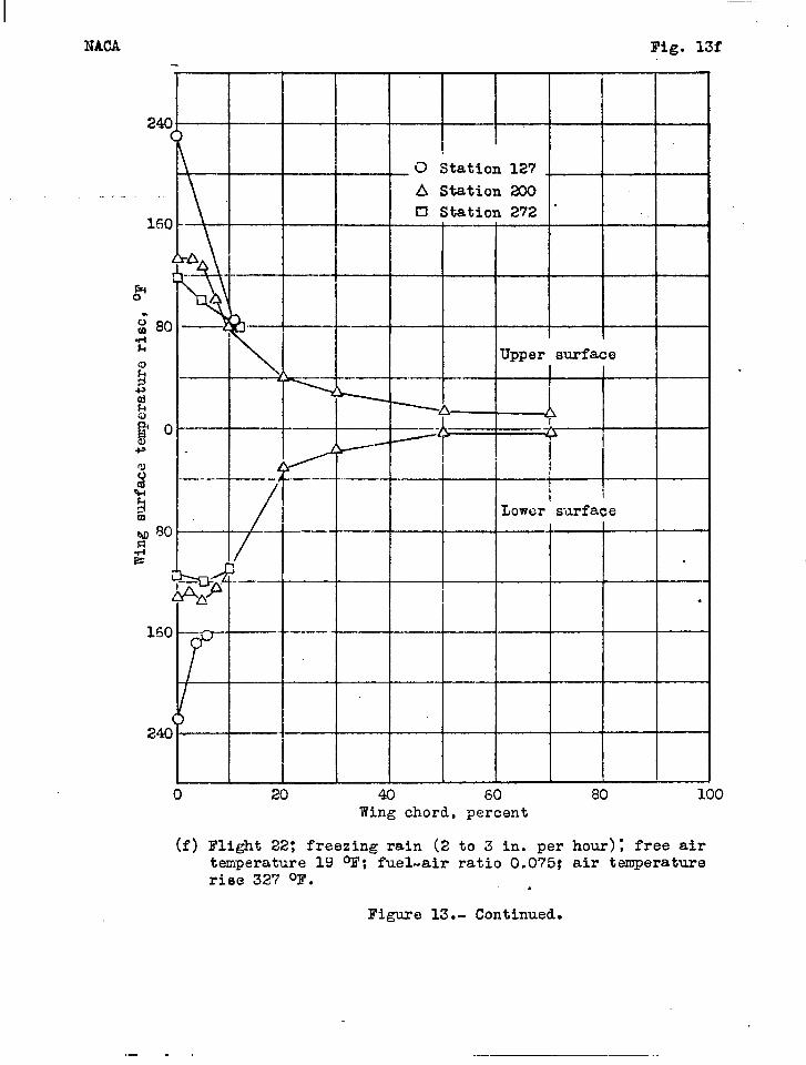
Fig. 13f
240 ‘
!
O Station 127 .
A Station 200El Station 272 “
150--
&A
~k.,’___
5 I
2“rrto 20 40 60
Wing chord, percent
(f) Flight 22; freezing rain (2 to 3 in. pertemperature 19 OF; fuel-air ratio 0.075:rise 327 oF. .
Figure 13.- Continued.
80 100
hour); free airair temperature
,... ,. ,
~--— ——
I?ACA Fig. 13g
I
240
““-’b
\,‘-t-
0 Station 127 ..
A Station 200
0 Station 272160
a I
‘*
1
)’~ ~–. ..---, .—
.: 80“’
a.&
‘- --@:w-
.02 ‘- —. I
~Oso:m: - “-f z;; ?? f
]
7
~ ,go -- — —. —..2i=
E
/WJ. .Q Lower surface..—.—-.—..—
w!-~ “
160—~ —“-- 1
—.—--..———-.— .
240 — ..
,0 20 46 60 80 100
Wing chord, percmt
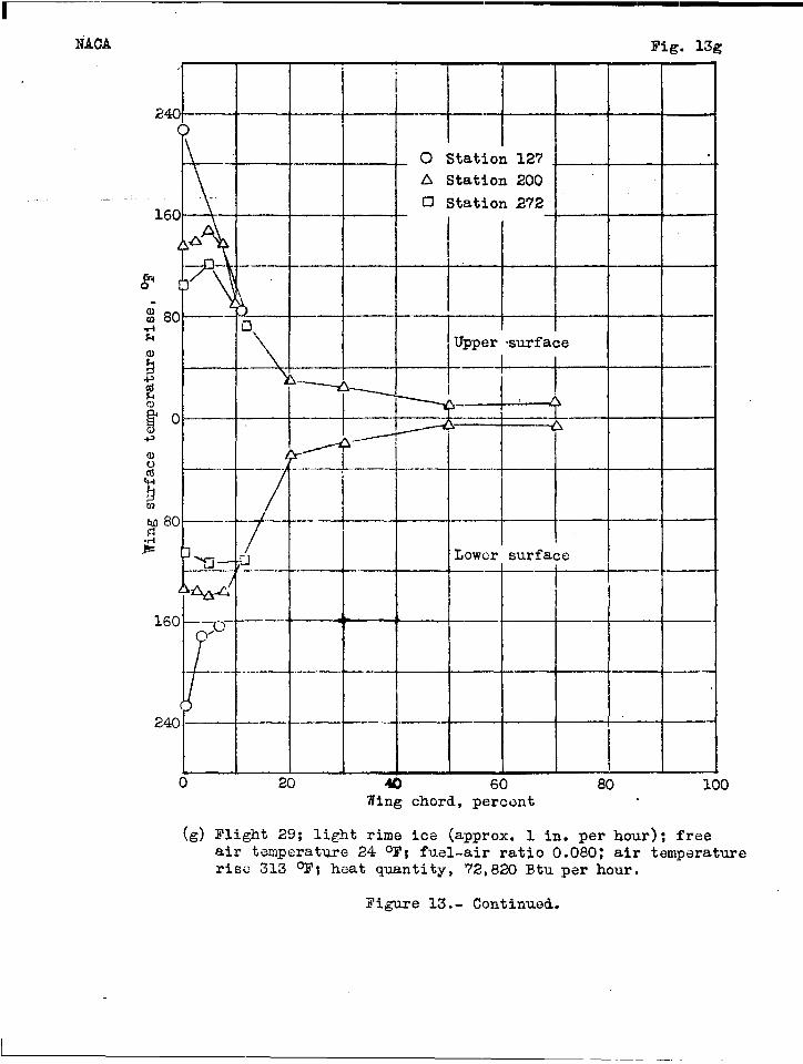
(g) Flight 29; light rime ice (approx. 1 in. per hour); freeair temperature 24 oF; fuel-air ratio 0.080: air temperaturerise 313 oF; heat quantity, 72,820 Btu per hour.
Figure 13.- Continued.
I—
NACA Fig. 13h
240 “--—
0 Station 127
A station 200 I.,. c I“U Station 272160
Upper surface. I: 90h
gI
&al$() — — —M
j —
~
h#80 - t .— —. —— .—
&’ !1
-—— -—
“ ‘T
.—. — .—.o
Lower eurface
—.. -—-—-
( --t-
-t- ,
—.—- ..——— — — -—--
---1
I— ——- .— -.-— . .— —...
240“ —
Lo 20 40 ;0 80 100
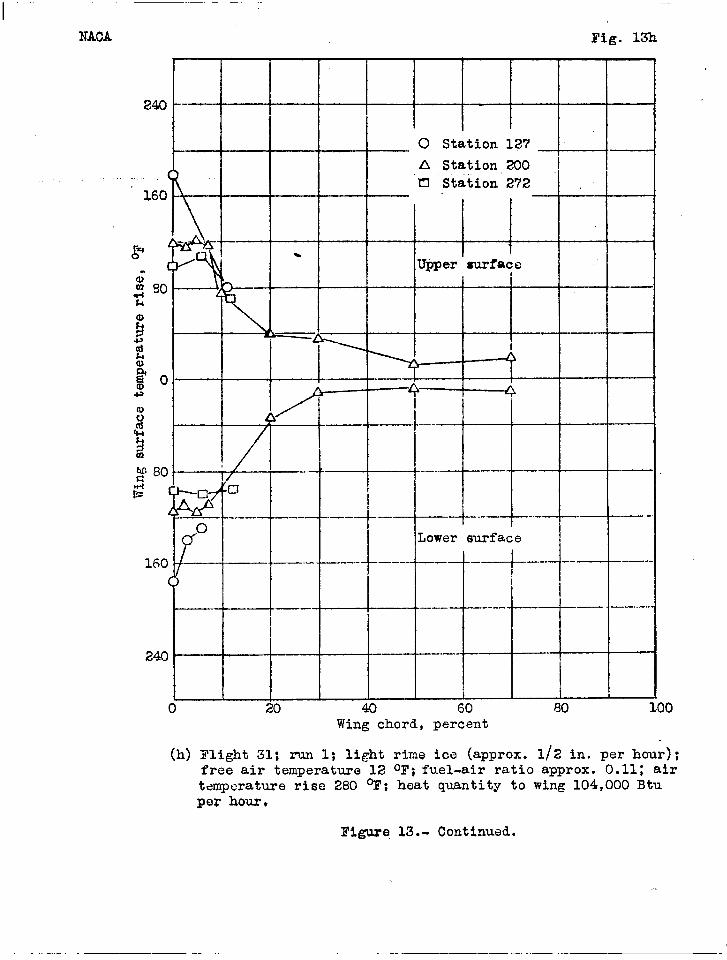
(h)
Wing chord, percent
Ilight 31; mm 1; light rime ice (approx. 1/2 in. per hour);free air temperature 12 oF; fuel-air ratio approx. 0.11: airtemperature rise 280 OF; heat quantity to wing 104,000 Btuper hour.
Figure 13.. Continued.
. . ... . ————-— --- ,, . . ..—-——. —.— ..-. ..,..— ..——
NACA Fig. 13i
I
240
0 Station 127
A Station 200
0 Station 272
&
~ 80 --WIh
‘--”-- r
~u)
aluG): ‘--
2 , ●
ovfersurface
160 -–.(~d– -
..——- . .
.-1--
I
-— ..- ——. —..—.——- . ——.
~~
+--———
[ [
240-—’-~— -
.—— ‘
i
I I i
o 20 40 60 80 100Wing chord, percent
(i) Flight 31: rm 2; rime ice (approx, 1 in. per hour); free.air temperature 10 ol?;fuel-air ratio 0.080: air temperaturerise 298 ~; heat quantity to wing 81,100 Btu per hour.
Figure 13.- Concluded.
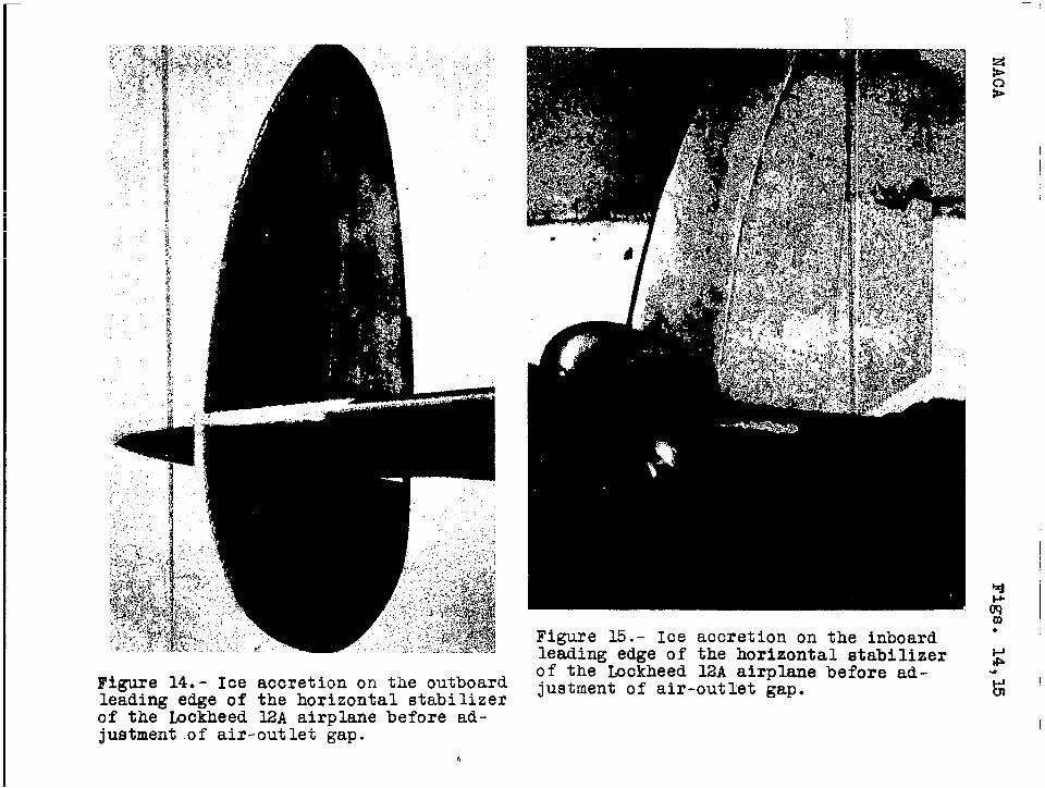
Figure 14. - Ice accretion on the outboardleading edge of the horizontal stabilizerof the Lockheed 1.2A airplane before ad-justment.of air-outlet gap.
b
Figure 15.- Ice accretion on the inboardleading edge of the horizontal stabilizerof the Lockheed 12A airplane before ad-justment of air-outlet gap.
I
1
Figure 16.- Ice formations during theprocess of removal from
the wing of the Lockheed 12A airplane.The wing was completely cleared within2 minutes after the application of heat.
Figure 1’7.- A typical ice formation on thewing tip of the Lockheed 12A airplane.
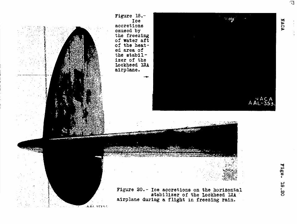
Figure 18.-Ice
accretionscaused bythe freezingof water aftof the heat-ed area ofthe stabil-izer of theLockheed 12Aairplane.
1
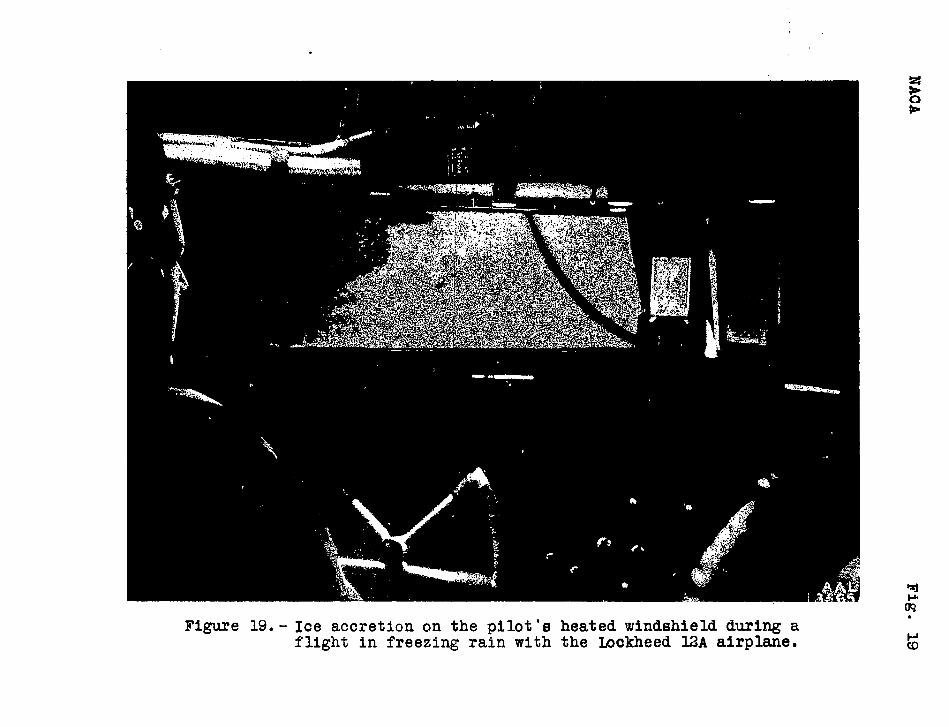
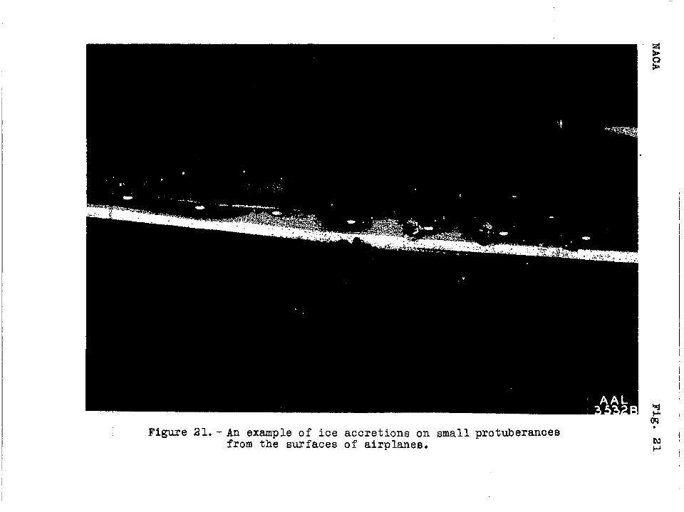
Figure 21. - An example of ice accretions on small protuberancesfrom the surfaces of airplanes.
I
I
I
I

i.;
J~llttttlL3 1176013646493