Embed Size (px)
Citation preview
NORTH AMERICAN STEEL SHEET PILING ASSOCIATION
500 MONTGOMERY STREET . SUITE 400 . ALEXANDRIA, VIRGINIA 22314 . TELEPHONE: 866.658.8667 . WWW.NASSPA.COM
NASSPA Annual, DFI Conference, SSP Symposium Meetings 13 – 17 October 2008
Hilton New York, NYC Planning Itinerary
Business casual dress
• 13 October – travel-on day to NYC; hotel check in (1) o No planned activities
• 14 October – NASSPA Annual Meeting; 9AM – 6 PM (2)
• 14 October – NASSPA Group Dinner; 7PM – 10PM (3)
• 15 October – DFI Conference activities (4)
o 8AM – 12PM – DFI committee meetings o 12PM – 1:30PM – DFI welcome lunch o 1:45PM – 4:35 PM – DFI technical session o 6PM – 8PM DFI welcome reception
• 15 October – NASSPA SSP Symposium speaker dinner; 7PM – 10PM (5)
• 16 October – DFI Conference activities (4)
o 8:30AM – 11:45 AM – DFI technical session o 12PM – 1PM – DFI business lunch o 1PM – 5:40PM – DFI technical session o 6:30PM – 9:15PM – DFI award reception and banquet
• 17 October – DFI conference activities; 8:30AM – 12:15 PM
• 17 October – NASSPA SSP Symposium; 12:30PM – 3:30PM (6)
• 17 October – travel-out after 3:30PM
(1) Hilton New York 1335 Avenue of the Americans (W.53rd and 6th) New York, NY 10019 (212) 586-7000 (2) Conference call access will be available (3) Carmines Theatre District – www.carminesnyc.com. Attending: NASSPA annual meeting attendees and
guests (4) go to www.deepfoundations08.org for conference details (5) The Palm, New York West Side – www.thepalm.com. Attending: NASSPA BOT, Correspondents,
Guests, SSP symposium speakers and guests. Meet at DFI welcome reception and leave for dinner at 7PM (6) NASSPA sponsored lunch included

NASSPA Confidential 9/10/08 Page 1
NASSPA meeting planner
companyBOT - Oct
14BOT Dinner -
Oct 14
NASSPA speaker
dinner - Oct 15
SSP Symposium -
Oct 17BOTBaucum GA Y Y Y YBilleke HSP Y Y Y YCrouch NYS YEngestrom NYS Y YEven AMMaedgen GA Y Y Y YMcShane AM Y Y
CorrespondantsFoster AD Y YKroell HSPMartins AM Y Y Y YReuter AMWhitaker GA Y Y Y Y
StaffGreenwald NASSPA Y Y Y YJolly TRP Y Y Y YDelano TRP Y Y
GuestsAbbondanza SL Borger SL YSchmidt AM Y Y YFagot AM Y Y YGarlich CE Y YRaj CE Y YGordon (presenting market study results) LCWA Y YWendt PPPetry PPWright LBFLenzen HSP Y Y Y YD. Foster LBF YD. Foster (spouse) LBF YSarapas LBF
SpeakersDempsey PND Y YHartman HE Y YDarling, B DC Y YDarling (spouse) DC YIngraffa KPFF y YMercurio CMX Y YGouda CMX Y YPierce PE Y Y
not attending
not attending
not attending
NORTH AMERICAN STEEL SHEET PIL ING ASSOCIATION
steel sheet pil ing . economical wall systems . steel sheet pil ing . retaining walls . steel sheet pil ing . permanent . cost effective . steel sheet pil ing . proven stabil ity . steel sheet pil ing . readily available . steel sheet pil ing . environmentally friendly . steel sheet pil ing . fastest . steel sheet pil ing steel sheet pil ing l sheet pil ing . readily available . steel sheet pil ing . environmentally friendly . steel sheet pil ing . steel sheet pil ing . steel sheet pil ing steel sheet pil ing . steel sheet pil ing steel sheet pil ing . readily available . steel sheet pil ing . steel sheet pil ing steel sheet pil ing . steel sheet pil ing steel sheet . pil ing steel sheet pil ing . economical wall systems . steel sheet pil ing . retaining walls . steel sheet pil ing . permanent . cost effective . steel sheet pil ing . proven stabil ity . steel sheet pil ing .
WALL COMPARISION Steel Sheet PilingGuide
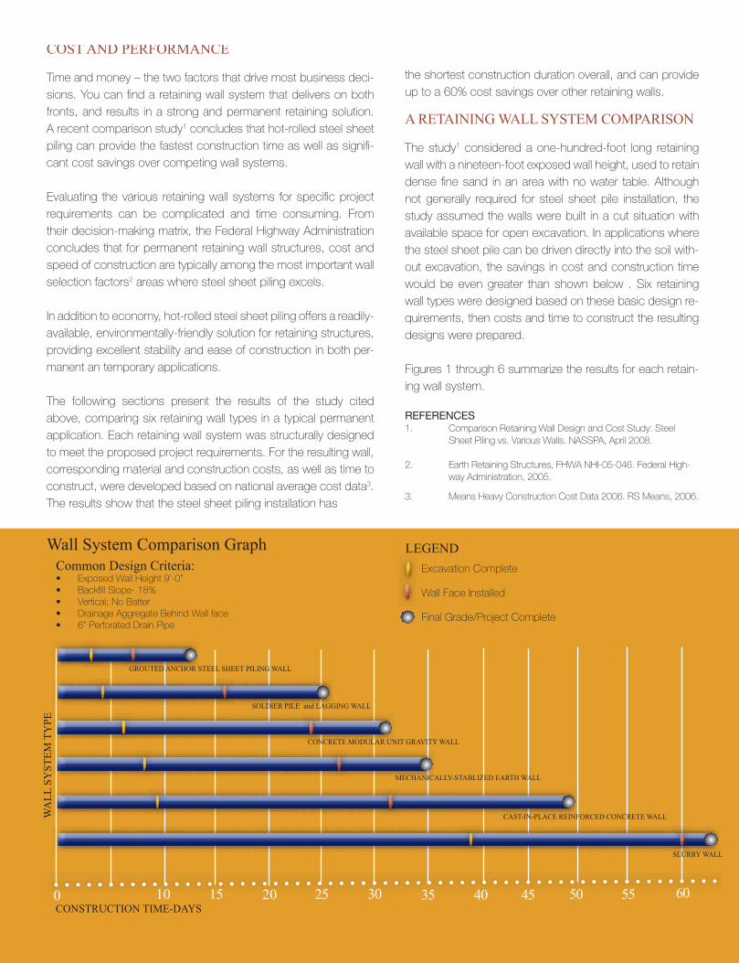
the shortest construction duration overall, and can provide up to a 60% cost savings over other retaining walls.
A RETAINING WALL SYSTEM COMPARISON
The study1 considered a one-hundred-foot long retaining wall with a nineteen-foot exposed wall height, used to retain dense fine sand in an area with no water table. Although not generally required for steel sheet pile installation, the study assumed the walls were built in a cut situation with available space for open excavation. In applications where the steel sheet pile can be driven directly into the soil with-out excavation, the savings in cost and construction time would be even greater than shown below . Six retaining wall types were designed based on these basic design re-quirements, then costs and time to construct the resulting designs were prepared.
Figures 1 through 6 summarize the results for each retain-ing wall system.
REFERENCES1. Comparison Retaining Wall Design and Cost Study: Steel Sheet Piling vs. Various Walls. NASSPA, April 2008.
2. Earth Retaining Structures, FHWA NHI-05-046. Federal High- way Administration, 2005.
3. Means Heavy Construction Cost Data 2006. RS Means, 2006.
COST AND PERFORMANCE
Time and money – the two factors that drive most business deci-sions. You can find a retaining wall system that delivers on both fronts, and results in a strong and permanent retaining solution. A recent comparison study1 concludes that hot-rolled steel sheet piling can provide the fastest construction time as well as signifi-cant cost savings over competing wall systems.
Evaluating the various retaining wall systems for specific project requirements can be complicated and time consuming. From their decision-making matrix, the Federal Highway Administration concludes that for permanent retaining wall structures, cost and speed of construction are typically among the most important wall selection factors2 areas where steel sheet piling excels.
In addition to economy, hot-rolled steel sheet piling offers a readily-available, environmentally-friendly solution for retaining structures, providing excellent stability and ease of construction in both per-manent an temporary applications.
The following sections present the results of the study cited above, comparing six retaining wall types in a typical permanent application. Each retaining wall system was structurally designed to meet the proposed project requirements. For the resulting wall, corresponding material and construction costs, as well as time to construct, were developed based on national average cost data3. The results show that the steel sheet piling installation has
Common Design Criteria:Exposed Wall Height 9’-0”Backfill Slope- 18%Vertical; No BatterDrainage Aggregate Behind Wall face6” Perforated Drain Pipe
Wall System Comparison Graph
WA
LL S
YST
EM T
YPE
CONSTRUCTION TIME-DAYS10 15 20 30 3525 40 45 50 55 600
GROUTED ANCHOR STEEL SHEET PILING WALL
SOLDIER PILE and LAGGING WALL
CONCRETE MODULAR UNIT GRAVITY WALL
MECHANICALLY-STABLIZED EARTH WALL
CAST-IN-PLACE REINFORCED CONCRETE WALL
SLURRY WALL
Excavation Complete
Wall Face Installed
Final Grade/Project Complete
LEGEND
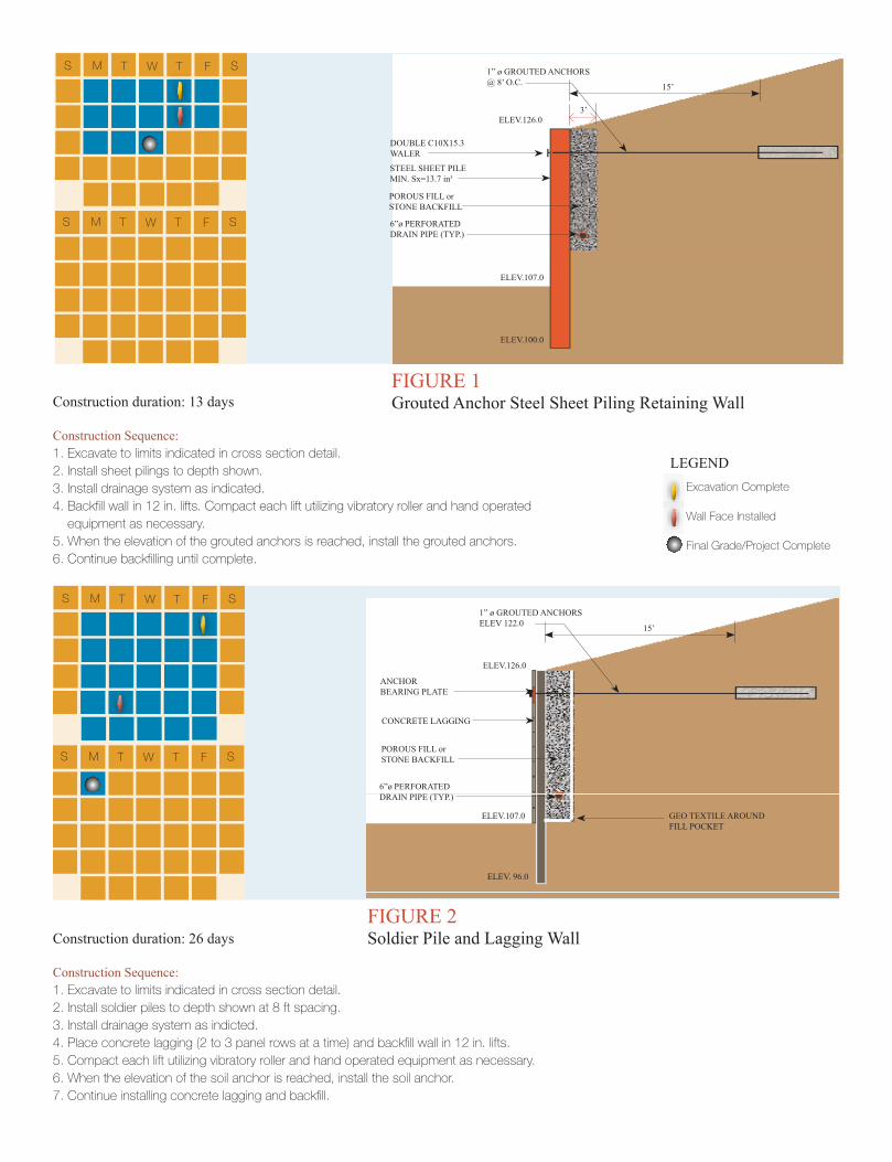
Construction duration: 13 days
Construction Sequence:1. Excavate to limits indicated in cross section detail.2. Install sheet pilings to depth shown.3. Install drainage system as indicated.4. Backfill wall in 12 in. lifts. Compact each lift utilizing vibratory roller and hand operated equipment as necessary.5. When the elevation of the grouted anchors is reached, install the grouted anchors.6. Continue backfilling until complete.
FIGURE 1 Grouted Anchor Steel Sheet Piling Retaining Wall
ELEV.126.0
ELEV.107.0
1” ø GROUTED ANCHORS@ 8’ O.C.
STEEL SHEET PILE MIN. Sx=13.7 in3
POROUS FILL or STONE BACKFILL
DOUBLE C10X15.3WALER
ELEV.100.0
6”ø PERFORATED DRAIN PIPE (TYP.)
3’
15’
S M T W T F S
S M T W T F S
Excavation Complete
Wall Face Installed
Final Grade/Project Complete
LEGEND
Construction duration: 26 days
Construction Sequence:1. Excavate to limits indicated in cross section detail.2. Install soldier piles to depth shown at 8 ft spacing.3. Install drainage system as indicted.4. Place concrete lagging (2 to 3 panel rows at a time) and backfill wall in 12 in. lifts.5. Compact each lift utilizing vibratory roller and hand operated equipment as necessary.6. When the elevation of the soil anchor is reached, install the soil anchor.
FIGURE 2 Soldier Pile and Lagging Wall
ELEV.126.0
ELEV.107.0
ELEV. 96.0
POROUS FILL or STONE BACKFILL
1” ø GROUTED ANCHORSELEV 122.0
ANCHOR BEARING PLATE
CONCRETE LAGGING
6”ø PERFORATED DRAIN PIPE (TYP.)
GEO TEXTILE AROUNDFILL POCKET
15’
S M T W T F S
S M T W T F S
ELEV.107.0
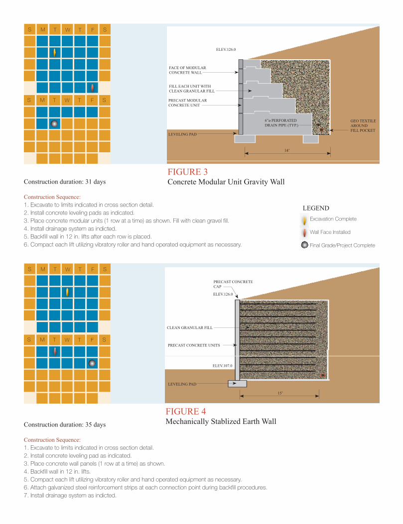
Construction duration: 31 days
Construction Sequence:1. Excavate to limits indicated in cross section detail.2. Install concrete leveling pads as indicated.3. Place concrete modular units (1 row at a time) as shown. Fill with clean gravel fill.4. Install drainage system as indicted.5. Backfill wall in 12 in. lifts after each row is placed.6. Compact each lift utilizing vibratory roller and hand operated equipment as necessary.
FIGURE 3 Concrete Modular Unit Gravity Wall
ELEV.126.0
FACE OF MODULAR CONCRETE WALL
FILL EACH UNIT WITH CLEAN GRANULAR FILL
PRECAST MODULAR CONCRETE UNIT
6”ø PERFORATED DRAIN PIPE (TYP.)
LEVELING PAD
GEO TEXTILE AROUNDFILL POCKET
14’
S M T W T F S
S M T W T F S
Excavation Complete
Wall Face Installed
Final Grade/Project Complete
LEGEND
Construction duration: 35 days
Construction Sequence: 1. Excavate to limits indicated in cross section detail.2. Install concrete leveling pad as indicated.3. Place concrete wall panels (1 row at a time) as shown. 4. Backfill wall in 12 in. lifts.5. Compact each lift utilizing vibratory roller and hand operated equipment as necessary.6. Attach galvanized steel reinforcement strips at each connection point during backfill procedures.
FIGURE 4 Mechanically Stablized Earth Wall
ELEV.126.0
ELEV.107.0
CLEAN GRANULAR FILL
PRECAST CONCRETE UNITS
LEVELING PAD
PRECAST CONCRETE CAP
15’
S M T W T F S
S M T W T F S
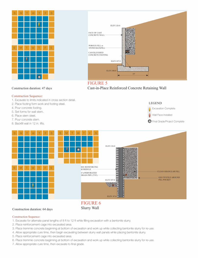
Construction duration: 47 days
Construction Sequence:1. Excavate to limits indicated in cross section detail.2. Place footing form work and footing steel.4. Pour concrete footing.5. Set forms for wall stem.6. Place stem steel.
8. Backfill wall in 12 in. lifts.
FIGURE 5 Cast-in-Place Reinforced Concrete Retaining Wall
ELEV.126.0
ELEV.107.0
ELEV.100.0
POROUS FILL or STONE BACKFILL
FACE OF CAST CONCRETE WALL
CANTILEVERED CONCRETE FOOTING
19’
S M T W T F S
S M T W T F S
Excavation Complete
Wall Face Installed
Final Grade/Project Complete
LEGEND
Construction duration: 64 days
Construction Sequence:1. Excavate for alternate panel lengths of 8 ft to 12 ft while filling excavation with a bentonite slurry.2. Place reinforcement cage into excavated area.3. Place tremmie concrete beginning at bottom of excavation and work up while collecting bentonite slurry for re-use.4. Allow appropriate cure time, then begin excavating between slurry wall panels while placing bentonite slurry.5. Place reinforcement cage into excavated area. 6. Place tremmie concrete beginning at bottom of excavation and work up while collecting bentonite slurry for re-use.
FIGURE 6 Slurry Wall
ELEV.126.0
ELEV.107.0GEO TEXTILE AROUNDFILL POCKET
ELEV. 87.0
CLEAN GRANULAR FILL6”ø PERFORATED DRAIN PIPE (TYP.)
SEE REINFORCING SCHEDULE
S M T W T F S S M T W T F S
S M T W T F S
steel sheet pil ing . economical wall systems . steel sheet pil ing . retaining walls . steel sheet pil ing . permanent . cost effective . steel sheet pil ing . proven stabil ity . steel sheet pil ing . readily available . steel sheet pil ing . environmentally friendly . steel sheet pil ing . fastest . steel sheet pil ing steel sheet pil ing l sheet pil ing . readily available . steel sheet pil ing . environmentally friendly . steel sheet pil ing . steel sheet pil ing . steel sheet pil ing steel sheet pil ing . steel sheet pil ing steel sheet pil ing . readily available . steel sheet pil ing . steel sheet pil ing steel sheet pil ing . steel sheet pil ing steel sheet . pil ing steel sheet pil ing . economical wall systems . steel sheet pil ing . retaining walls . steel sheet pil ing . permanent . cost effective . steel sheet pil ing . proven stabil ity . steel sheet pil ing .
N O R T H A M E R I C A N S T E E L S H E E T P I L I N G A S S O C I A T I O N
Copyright © 2008
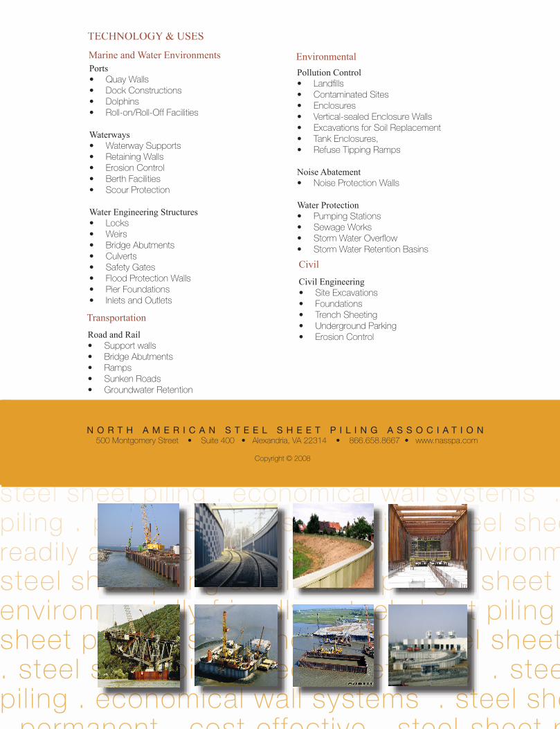
TECHNOLOGY & USES
PortsQuay Walls Dock Constructions Dolphins Roll-on/Roll-Off Facilities
WaterwaysWaterway SupportsRetaining Walls Erosion ControlBerth Facilities Scour Protection
Water Engineering StructuresLocks Weirs Bridge Abutments CulvertsSafety Gates Flood Protection WallsPier Foundations Inlets and Outlets
Marine and Water Environments EnvironmentalPollution Control
LandfillsContaminated Sites EnclosuresVertical-sealed Enclosure Walls Excavations for Soil ReplacementTank Enclosures, Refuse Tipping Ramps
Noise AbatementNoise Protection Walls
Water ProtectionPumping Stations Sewage Works Storm Water Overflow Storm Water Retention Basins
Civil EngineeringSite ExcavationsFoundationsTrench Sheeting Underground ParkingErosion Control
Civil
Transportation
Road and RailSupport wallsBridge AbutmentsRampsSunken RoadsGroundwater Retention
SEPTEMBER 2008 MODERN STEEL CONSTRUCTION
. HKS.lnc.
move to create an 85--ft-tall x 21O-tt-wide opening: Each panel rides on a steel rail while the wall opens and doses, and is supported by two hardened steel wheels,
certificate. The objective of the survey is to improve the certification process from invoicing to the audit to issuing the certificate, and companies that complete the survey are automatically entered into the drawing. QMC will draw for another free audit in six months, so keep those surveys coming in!
news & events
Indiana Fabricator Wins Free Audit
PROJECTS
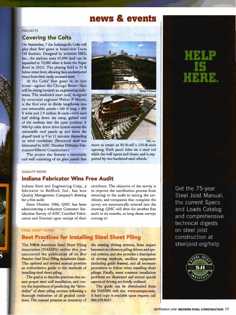
Covering the Colts On September, 7 the Indianapolis Colts will play their first game at brand-new Lucas Oil Stadium. Designed by architect HKS, Inc., the stadium seats 63,000 (and canbC expanded to 70,000 when it hosts the Super Bowl in 2012). The playing field is 25 ft below ~eet leve~ allowing funs unobstructed views from their easily accessed seats.
At the Colts' first game in its new home-against the Chicago Bears-fans will be sitting beneath an engineering milestone. The stadium's steel roof, designed by structural engineer Walter P Moore, is the first ever to divide lengthwise into two retractable panels-160 ft long x 600 ft wide an<:l2.9 million Ib each-with each half sliding down the steep, gabled roof of the stadium into the open position. A 960-hp cable drum drive System moves the retractable roof panels up and down the sloped track in 9 to 11 minutes depending on wind conditions. (Structural steel was fabricated by AISC Member Hillsdale Fab~icatorslAlberici Constructors.)
The project also features a retractable end wall consisting of six glass panels that
QUALITY NEWS
Indiana Steel and Engineering Corp., .a fabricator' in Bedford, Ind., has won Quality Management Company's drawing for a free audit.
Since October 2006, QMC has been administering a voluntary Customer Satisfaction Survey of AISC Certified Fabricators and Erectors' upon receipt of their
Best Prac;.tices· for Installin~1' Steel Sheet Piling . . ,
The Nt1rth American Steel Sheet Piling the existing driving systems, from impact Association (NASSPA) earlier. this year hammers to vibratory piling drivers andspeannounced the publication of its Bes.t cial systems, and also provides a description Practices Steel Sheet Piling Installation Guide. of driving methods, ancillary equipment This updated and revised manual provides (including guide frames), and all necess~ry
an authoritative guide to the methods of procedures to follow when installing sheet . installing steel sheet piling. pilings. Finally, some common installation'
The goal is to describe practices that en- problems are illustrated and se~eral special sure proper steel wall installation, and con- aspects of driving are briefly outlined. -vey the inlportance of predicting the "drive- The guide can be downloaded from ability" of sheet piling sections following a the NASSPA web site, www.nasspa.com. thorough evaluation of all groUnd condi- A hard copy is available upon request; call tions. The manual presents an inventory of 866~658.8667.
19