Embed Size (px)
Citation preview
NASA Technical Memorandum 102756NASA-TM-102756 19910008807
MECHANICAL PROPERTIES OF THEa
FIBERGLASS PREPREG SYSTEMUSED FOR THE NATIONAL TRANSONICFACILITY REPLACEMENT BLADE SET
Clarence P. Young, Jr. and John W. Wallace
FEBRUARY 1991
Nalional Aeronautic,*; and
SpaceAdministration _,I_RI _ 199!Langley Research CenterHamplon,Virginia23665-5225 LANGLEYRESEARCHCENTERLIBRARyNA_*_,
"_. HAMHON,VIRGINIA
https://ntrs.nasa.gov/search.jsp?R=19910008807 2018-05-24T05:50:37+00:00Z

Contents
List of Tables and Figures .............................. ii
Summary ..................................... 1
List of Symbols ................................... 1
Introduction .................................... 2
Material Layup Description ............................. 2
Mechanical Properties Tests ............................. 3
Tensile ............. ........................ 3
Compression ................................... 5
Interlaminar Shear ................................ 6
Fatigue ..................................... 6
Thermal Expansion ................................ 7
Creep ...................................... 7
Thermal Cycling ................................. 8
Additional Tests .................................. 8
Evaluation of Tensile and Fatigue Properties for Design Requirements ........... 9
Concluding Remarks ............................... 10
Recommendations ................................. 10
References .................................... 10
b<jU]l - ,i
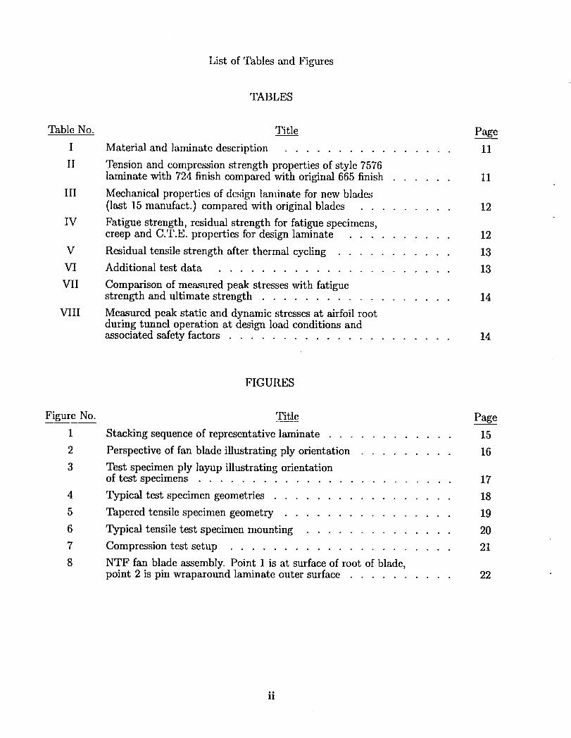
List of Tables and Figures
TABLES
Table No. Title Page
I Material and laminate description ................ 11
II Tension and compression strength properties of style 7576laminate with 724 finish compared with original 665 finish ...... 11
III Mechanical properties of design laminate for new blades(last 15 manufact.) compared with original blades ......... 12
IV Fatigue strength, residual strength for fatigue specimens,creep and C.T.E. properties for design laminate .......... 12
V Residual tensile strength after thermal cycling ........... 13
VI Additional test data ...................... 13
VII Comparison of measured peak stresses with fatiguestrength and ultimate strength .................. 14
VIII Measured peak static and dynamic stresses at airfoil rootduring tunnel operation at design load conditions andassociated safety factors ..................... 14
FIGURES
Figure No. Title Page
1 Stacking sequence of representative laminate ............ 15
2 Perspective of fan blade illustrating ply orientation ......... 16
3 Test specimen ply layup illustrating orientationof test specimens ........................ 17
4 Typical test specimen geometries ................. 18
5 Tapered tensile specimen geometry ................ 19
6 Typical tensile test specimen mounting .............. 20
7 Compression test setup ..................... 21
8 NTF fan blade assembly. Point 1 is at surface of root of blade,point 2 is pin wraparound laminate outer surface .......... 22
ii
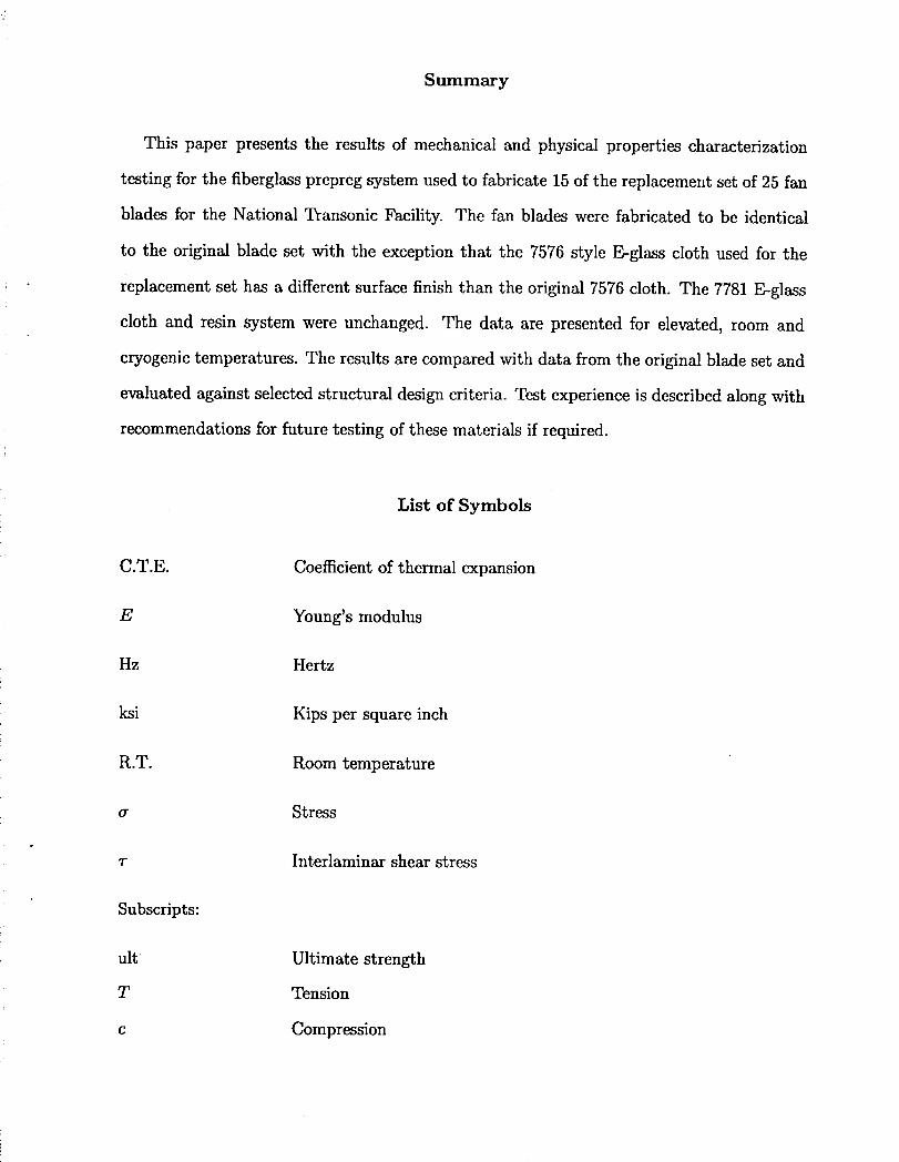
Summary
This paper presents the results of mechanical and physical properties characterization
testing for the fiberglass prepreg system used to fabricate 15 of the replacement set of 25 fan
blades for the National Transonic Facility. The fan blades were fabricated to be identical
to the original blade set with the exception that the 7576 style E-glass cloth used for the
replacement set has a different surface finish than the original 7576 cloth. The 7781 E-glass
cloth and resin system were unchanged. The data are presented for elevated, room and
cryogenic temperatures. The results are compared with data from the original blade set and
evaluated against selected structural design criteria. Test experience is described along with
recommendations for future testing of these materials if required.
List of Symbols
C.T.E. Coefficient of thermal expansion
E Young's modulus
Hz Hertz
ksi Kips per square inch
R.T. Room temperature
a Stress
T Interlaminar shear stress
Subscripts:
ult Ultimate strength
T Tension
c Compression
Introduction
As a result of a mishap in the National Transonic Facility on .January 18, 1989, all 25 fan
blades were destroyed. The blades were destroyed due to the high energy release of metallic
parts from the drive shaft external thermal barrier retainer band. These parts impacted
metallic aerodynamic fairing plates releasing them into the air stream. Several metallic
plates passed through the fan damaging all 25 blades beyond repair.
The fiberglass prepreg system used for the original blade set was tested extensively and
reported in references 1 and 2. Two fiberglass cloths (7781 E-glass and 7576 E-glass) were
used to fabricate the blades. Ten blades manufactured from this system were on hand at
the time of the mishap. However, for the last 15 blades, the 7576 prepreg material was
no longer available with the VM 665 finish. At the recommendation of the manufacturer,
the CS-724 finish was selected. As a result of this diffcrcnce, a comprehensive mechanical
and physical properties characterization of the 7576 laminate and the design (representative)
laminate was carried out in order to assure that the mechanical and physical properties of
the modified system met the design requirements. The approach was to follow the same test
procedures and use the same test specimen designs and test methods that were used in the
original characterization program described in references 1 and 2.
The purpose of this paper is to document the results of the mechanical and physical
properties tests of the fiberglass prepreg materials used for 15 of the replacement blades
installed in the National Transonic Facility in 1989.
Material I, ayup Description
As previously mentioned, two styles of fiberglass cloth pre-impregnated with an epoxy
resin system were used for the fan blades. The 7781 style E-glass cloth has a ratio of 60 fibers
in the warp direction to 54 in the fill direction. The second material is the 7576 style cloth
which has a ratio of 120 fibers in the warp direction to 24 in the fill direction (see table I).
The stacking sequence for the design (representative) laminate is shown in figure 1 and a
2
perspective of tile blade illustrating the design layup is given in figure 2. Test specimens
were cut from panels (ply layups) in the warp (0 ° direction) and fill (90° direction) direction
as illustrated in figure 3. Panels were fabricated separately for the two cloths and for the
actual design laminate layups. It should be noted that these panels are representative of the
design laminate, and referred to in references 1 and 2 as the representative laminate. The
panels were taken through the sazne cure cycles as the actual blades. Emphasis was placed
on testing specimens taken in the warp direction which is the direction of principal loading
in the fan blade. The reader is referred to references 1 and 2 for a more detailed description
and discussion of the material system.
Mechanical Properties Tests
The intent of the test program was to use the same type specimens and test equipment as
those used for the previous fan blade material characterization tests at the Langley Research
Center (LaRC) (references 1 and 2). This approach would utilize previous test experience
and provide a basis for direct comparison of the data to that for the original blade set.
However, a number of mechanical/specimen problems were encountered in various tests and
are discussed later in the paper.
Mechanical and physical properties characterization was carried out at elevated (200°F),
room and cryogenic (-300°F) temperature in the 0° direction (principal loading direction).
Also, a limited number of tests were conducted in the 90° direction, and, although not
reported herein, these tests gave very good agreement with previously reported values.
Reported values are the average for three specimens unless otherwise noted. The various
tests and results are discussed in the following sections.
Tensile
i The American Society for Testing and Materials (ASTM) D3039-6 method was used to
test the tensile specimens. The tensile specimen geometry is shown in figure 4. Problems were
I encountered in testing this straight sided specimen, particularly at cryogenic temperatures.
Specimens with both tapered and square tabs were tested but little difference between
performance was noted. The major problems were either (1) failure in the grip area, or
(2) tab failure (shear surface between the tab and specimen). Very few specimens failed in
the gage portion of the test specimen. Other related problems included (1) specimen size
(too long for testing in the LaRC Structures and Materials Laboratory cryo chambers for the
case where both the specimen and grips need to bc cooled) and (2) lack of hydraulic grips on
the Instron machine that was used to test specimens to failure at cryogenic temperatures.
A number of things were tried in an attempt to alleviate the aforementioned problems;
these included, (1) different adhesive between specimen and grip tabs, (2) pin plus adhesive,
(3) rivets in tabs plus adhesive, and (4) tapering (necking down) the specimen over the
original straight-sided gage length. Finally, a tensile specimen made from the geometry
illustrated in figure 5 worked to the extent the failure loads were near or equal to expected
values before either the tabs failed, or the specimens failed across the net gage section. A
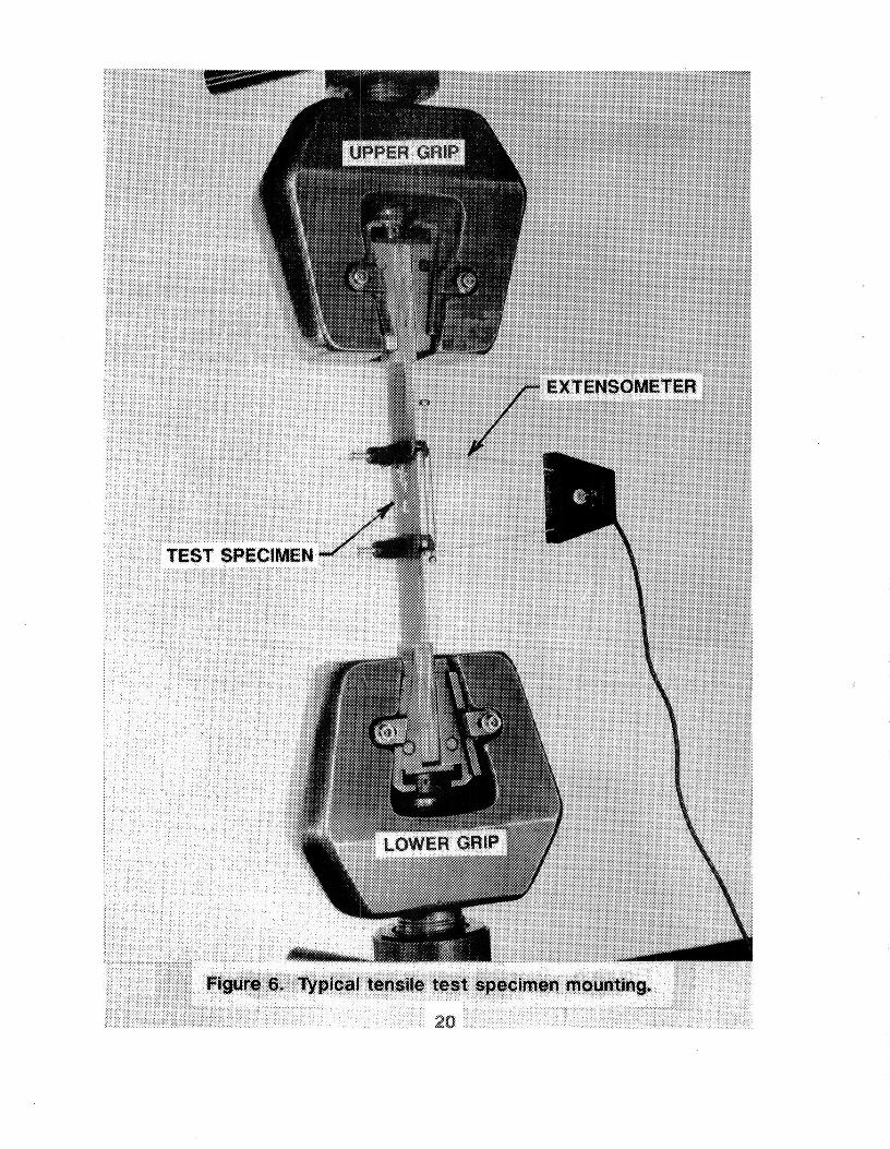
typical instrumented test specimen mounting arrangement is illustrated in figure 6.
It is recommended that for any future testing the specimen geometry shown in figure 5 be
used particularly for cryogenic temperatures. Straight-sided specimens (believed to reduce
interaction effects in cross ply layups) should be avoided. Also consideration should be given
to scaling down the specimen length to the extent that it can be tested in the machines
already equipped with cryogenic chambers and hydraulic grips which are located in the
LaRC Structures and Material Laboratories.
Because of the aforementioned problems, modulus values (based on extensiometer data)
were obtained at cold temperatures in the LaRC materials laboratory where tile gage portion
of the specimen was cooled but not the grips.
The tensile strength results for the 7576 cloth with the 724 finish arc given in table II
and compared with values obtained for the original 665 finish. The tensile values for the 724
finish are slightly lower and follows the trend of data obtained from the manufacturer for the
two finishes. The value given at -300°F does not represent a tensile failure in the specimen
4
,3
:i
material but is based on failure loads resulting from tab failure (shear) which indicates that
the material tensile strength should be as good or better than the average value given in
the table. However, failure indications in the laminate were evident in all specimens and
appeared to start at the slight radius transition between the taper and gage (straight sided)
portion of the specimen shown in figure 5. The tensile strength and Young's modulus data
are given in table III for the design laminate and are compared with the previously reported
values given in reference 1. It is seen that the ultimate tensile strength for the design laminate
is slightly lower at elevated and room temperature. The average value at -300°F (based
on one tensile failure in the gaged section and one in which tile tabs slipped on two other
specimens) is also lower than the value reported for the original blade set material.
The Young's tensile modulus data given in table III for the design laminate were about
:! 16 percent lower than the values reported in references 1 and 2. However, comparison with
Young's modulus data obtained from fatigue specimens for the original blade set but not
reported in the references gave excellent agreement. Although reasons for differences between
the reported values of references 1 and 2 and the results from these tests are not understood
they are still acceptable with regard to blade stiffness requirements. Also, it should be
noted that the results of modal (vibration) testing did not show any significant differences in
fundamental vibration frequencies for the last 15 blades manufactured when compared with
the first 10 blades manufactured from the original material. In addition, the average value
for the new blade set first mode frequency is 66.1 Hz compared to 57 Hz for the original blade
set, which implies increased stiffness. This observation further supports the acceptability of
• the Young's modulus for the material.
Compression
The ASTM D3410-75 test method was used as a guideline for compressive testing (see
fig. 7 for typical test setup) of the fan blade material. The reader is referred to references 1
and 2 for details on the procedure as it was basically unchanged and worked very well. The
compression specimen geometry is shown in figure 4. The compression strength and modulus
5
data are summarized for the 0° direction specimens in tables II and III. As indicated, the
compression strength is greater than previously reported vahms for both the 7576 cloth and
the design laminate, especially at -300°F. Also note from table III, the excellent agreement
in compression modulus values.
Intcrlaminar Shear
The test method used to determine interlaminar shear strength was the "guillotine"
method using the standard fixture and is described in detail in reference 1. The reader is
referred to reference 1 for detailed information on curing of specimens, etc. These tests were
performed only on the representative (design) laminate. The interlaminar shear strength
values are given in table III. Note that the average values are lower when compared to
the original blade data (approx. 5 to 17% reduction). However the trend of strength with
temperature is the same and the blades are not highly loaded in shear.
Fatigue
The design laminate fatigue specimens were tested in the same manner as reported in
references 1 and 2 using the ASTM D3479-76 test method. The load-control tests were
conducted at a frequency of 10 Hz and at a stress ratio of .01. These tests were conducted
at the stress level (30% of ultimate strength at room temperature) used as the allowable for
fan blade design with a goal of 1 million cycles without failure.
The fatigue specimen is the same length and thickness as the tensile specimen but is
lV2 inches in width. (See fig. 4.) Tile procedures described in references 1 and 2 were
followed for fatigue testing at elevated and cryogenic temperatures. However, problems were
encountered such as (1) failure at a lower number of cycles than expected and (2) failures in
the grip area. It was found that premature fatigue specimen failures were associated with
testing at a higher stress ratio (0.1 instcad of .01), and with failure of the tabs in shear
at the bond plane, or failure of the material in the grip area. After correcting for stress
ratio, changing adhesives and varying grip pressures, tests were successfully completed for
the design laminate in the 0° direction. The results are given in table IV and demonstrate
6
that fatigue properties meet the design requirement of >30% of ultimate strength at elevated
temperatures and 30% of the room temperature ultimate at ambient and cryogenic (-300°F)
temperatures.
The fatigue specimens were tested for residual strength after cycling. The design laminate
residual strength values for the fatigue specimens (obtained from tensile tests after 1 million
cycles) were as good and in some cases higher than those obtained from the pure tensile
tests. It is believed that the differences are attributed to specimen geometry differences (the
fatigue specimen is wider than the tensile specimens and probably more stable) and also to
failures in the tab regions for the smaller tensile specimens. (It should be noted that some
of the fatigue tensile specimens also failed in the grip area.) The residual strength results
are presented in table III.
Thermal Expansion
The linear coefficient of thermal expansion tests were performed in the 0° and 90°
directions for the representative laminate using a DuPont 943 Thermomechanical Analyzer.
The analyzer was calibrated using a known aluminum standard. This state-of-the-art
instrument was used because the accuracy is better than the method used for the original
blade set and the equipment used in the original tests was not available. Additionally, the
analyzer gave continuous measurements as opposed to end points. The results are tabulated
in table IV for the temperature ranges of room temperature (RT) to 200°F, and RT to
-300°F. The results compare very well with design laminate (both the 0° and 90° direction)
values obtained for the original blade set.
Creep
The test method for establishing tensile creep properties is ASTM D2990-77. The method
and procedure is described in detail in reference 1. Three design laminate specimens (see
fig. 4) were loaded to 18.8 ksi (approximately 30% ult. at 200°F) and elastically strained
to 0.57 percent. The results are given in table IV and compared to values reported in the
reference. As reported in reference 2, for the previous tests, the specimen(s) were loaded
7
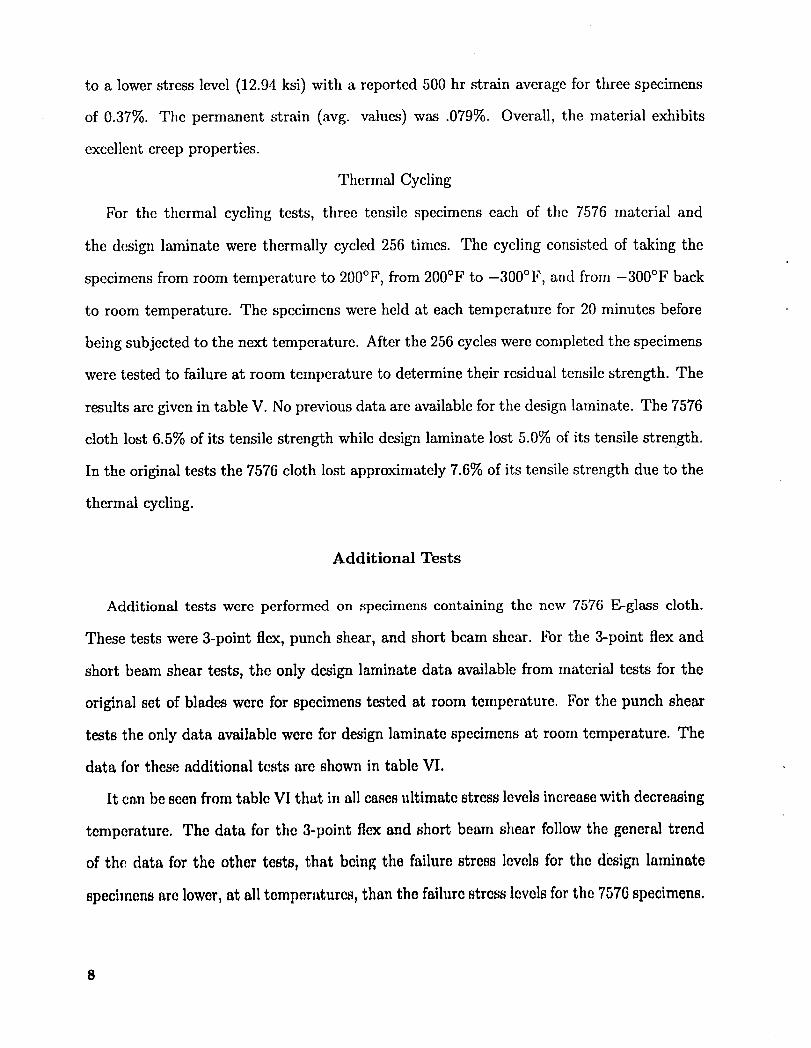
to a lower stress level (12.94 ksi) with a reported 500 hr strain average for three specimens
of 0.37%. The permanent strain (avg. values) was .079%. Overall, the material exhibits
excellent creep properties.
Thermal Cycling
For the thermal cycling tests, three tensile specimens each of the 7576 material and
the design laminate were thermally cycled 256 times. The cycling consisted of taking the
specimens from room temperature to 200°F, from 200°F to -300°F, and from -300°F back
to room temperature. The specimens were held at each temperature for 20 minutes before
being subjected to the next temperature. After the 256 cycles were completed the specimens
were tested to failure at room temperature to determine their residual tensile strength. The
results are given in table V. No previous data are available for the design laminate. The 7576
cloth lost 6.5% of its tensile strength while design laminate lost 5.0% of its tensile strength.
In the original tests the 7576 cloth lost approximately 7.6% of its tensile strength due to the
thermal cycling.
Additional Tests
Additional tests were performed on specimens containing the new 7576 E-glass cloth.
These tests were 3-point flex, punch shear, and short beam shear. For the 3-point flex and
short beam shear tests, the only design laminate data available from material tests for the
original set of blades were for specimens tested at room temperature. For the punch shear
tests the only data available were for design laminate specimens at room temperature. The
data for these additional tests are shown in table VI.
It can be seen from table VI that in all cases ultimate stress levels increase with decreasing
temperature. The data for the 3-point flex and short beam shear follow the general trend
of the data for the other testsy that being the failure stress levels for the design laminate
specimens are lower, at all temperatures, than the failure stress levels for the 7576 specimens.
8
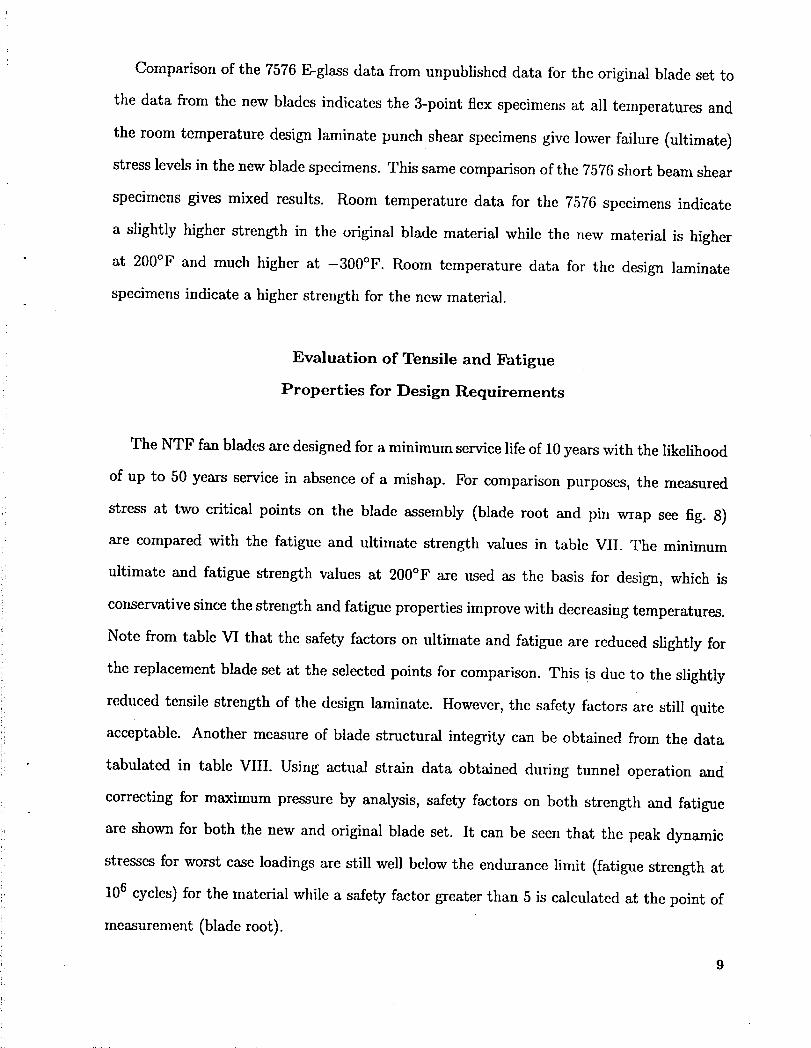
Comparison of the 7576 E-glass data from unpublished data for the original blade set to
the data from the new blades indicates the 3-point flex specimens at all temperatures and
the room temperature design laminate punch shear specimens give lower failure (ultimate)
stress levels in the new blade specimens. This same comparison of the 7576 short beam shear
specimens gives mixed results. Room temperature data for the 7576 specimens indicate
a slightly higher strength in tile original blade material while the new material is higher
at 200°F and much higher at -300°F. Room temperature data for the design laminate
specimens indicate a higher strength for the new material.
Evaluation of Tensile and Fatigue
Properties for Design Requirements
The NTF fan blades are designed for a minimum service life of 10 years with the likelihood
of up to 50 years service in absence of a mishap. For comparison purposes, the measured
stress at two critical points on the blade assembly (blade root and pin wrap see fig. 8)
are compared with the fatigue and ultimate strength values in table VII. The minimum
ultimate and fatigue strength values at 200°F are used as the basis for design, which is
conservative since the strength and fatigue properties improve with decreasing temperatures.
Note from table VI that the safety factors on ultimate and fatigue are reduced slightly for
i the replacement blade set at the selected points for comparison. This is due to the slightly
reduced tensile strength of the design laminate. However, the safety factors are still quite
_: acceptable. Another measure of blade structural integrity can be obtained from the data!
tabulated in table VIII. Using actual strain data obtained during tunnel operation and
correcting for maximum pressure by analysis, safety factors on both strength and fatigue
are shown for both the new and original blade set. It can be seen that the peak dynamic
stresses for worst case loadings are still well below the endurance limit (fatigue strength at
106 cycles) for the material while a safety factor greater than 5 is calculated at the point of
measurement (blade root).
9
Concluding Remarks
The mechanical and physical properties of the fiberglass prepreg system for the National
Transonic Facility replacement blade set are presented. The 7576 cloth with the 724 surface
finish gives acceptable properties. The representative (design) laminate properties for the
new blade set compare well with those for the original blade set, and meet structural design
requirements. Some differences between Young's tensile modulus and that reported from
previous tests were observed, but are of no consequence insofar as structural design properties
acceptability. Numerous problems were encountered in obtaining acceptable test results.
Chief among these were specimen tab failures, grip region failures and equipment limitations,
particularly for cryogenic tcsting.
Recommendations
It is recomnmnded that tapered (instead of straight sided) specimens and different tab
geometries be used for any future tensile testing and fatigue testing of the fan blade materials.
Also tile specimen(s) should be sized such that they can be tested in existing machines with
required load and environmental capability for subjecting the entire specimen (including test
machine grips) to the required test temperature.
References
1. Klich, P. J. and Cockrell, C. E.: Mechanical Properties of a Fiberglass Prepreg System
at Cryogenic and Other Temperatures. AIAA Journal Volume 21, December 1983,
Page 1772.
2. Klich, P. J., Richards, W. H. and Ahl, E. L., Jr.: National Transonic Facility Fan Blade
Prepreg Material Characterization Tests. NASA TM 81800, July 1981.
10
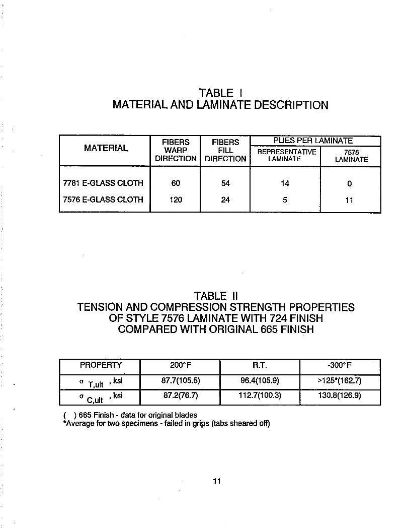
TABLE IMATERIALAND LAMINATEDESCRIPTION
FIBERS FIBERS PLIESPERLAMINATEMATERIAL WARP FILL REPRESENTATIVE 7576
DIRECTION DIRECTION LAMINATE LAMINATE
7781 E-GLASSCLOTH 60 54 14 0
7576 E-GLASSCLOTH 120 24 5 11
TABLE IITENSIONAND COMPRESSIONSTRENGTHPROPERTIES
OF STYLE7576 LAMINATEWITH 724 FINISHCOMPAREDWITH ORIGINAL665 FINISH
PROPERTY 200°F R.T. -300°F
a T,ult ' ksi 87.7(105.5) 96.4(105.9) >125"(162.7), ksi 87.2(76.7) 112.7(100.3) 130.8(126.9)a C,ult
( ) 665 Finish- datafororiginalblades*Averagefortwospecimens- failedingrips(tabsshearedoff)
11
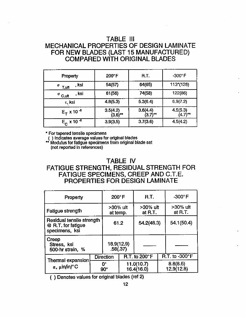
TABLE IIIMECHANICALPROPERTIESOF DESIGNLAMINATE
FOR NEW BLADES(LAST 15 MANUFACTURED)COMPAREDWITH ORIGINALBLADES
Property 200°F R.T. -300°F
o T,ult ,ksi 54(57) 64(65) 113"(128), ksi 61(56) 74(58) 122(86)o C,ult
• , ksi 4.8(5.3) 5.3(6.4) 6.9(7.2)
ET x 10 "_ 3.5(4.2) 3.6(4.4) 4.5(5.3)(3.6)** (3.7)** (4.7)**
Ec x 10-8 3.9(3.5) 3.7(3.6) 4.5(4.2)
• Fortaperedtensilespecimens( ) Indicatesaveragevaluesfororiginal blades
•* Modulusforfatiguespecimensfromoriginalbladeset(not reportedinreferences)
TABLE IVFATIGUESTRENGTH, RESIDUALSTRENGTHFOR
FATIGUESPECIMENS,CREEPAND C.T.E.PROPERTIESFOR DESIGN LAMINATE
Property 200°F R.T. -300°F
>30%ult >30%ult >30%ultFatiguestrength attemp. at R.T. atR.T.Residualtensilestrength@ R.T.forfatigue 61.2 54.2(48.3) 54.1(50.4)specimens,ksi
CreepStress,ksi 18.9(12.9)500-hrstrain,% .58(.37)
Direction R.T.to200°F R.T. to-300°FThermalexpansion
=, pin/in/°C 0° 11.0(10.7) 8.8(8.6)90° 16.4(16.0) 12.9(12.8)
( ) Denotesvaluesfororiginalblades(ref2)12

TABLE VRESIDUALTENSILESTRENGTH
AFTERTHERMALCYCLING
7576 E-Glass DesignLaminate
90.1(97.9) ksi 60.6 ksi
( ) Indicatesdata from originalblade set
TABLE VIADDITIONALTEST DATA
a. 3-Pointflex
Temperature 7576E-Glass DesignLaminate
200°F 106.8(121.0)ksi 77.3 ksiR.T. 122.6(140.9)ksi 88.9(101.6)ksi
-300°F 234.9(244.7)ksi 187.0ksi
b. Short beamshear
Temperature 7576 E-Glass DesignLaminate
200°F 8.1(6.8)ksi 8.4 ksiR.T. 11.0(11.4)ksi 10.9(8.6)ksi
-300°F 37.0(18.7)ksi 16.3 ksi
c. Punchshear
Temperature 7576E-Glass DesignLaminate
200°F 15.5ksi 18.8 ksiR.T. 17.7ksi 22.3(26.7)ksi
-300°F 30.7 ksi >37.2 ksi*
*Shearloadexceededmachinecapacityof 20,000Ibf.( ) Indicatesdatafromoriginalbladeset
13
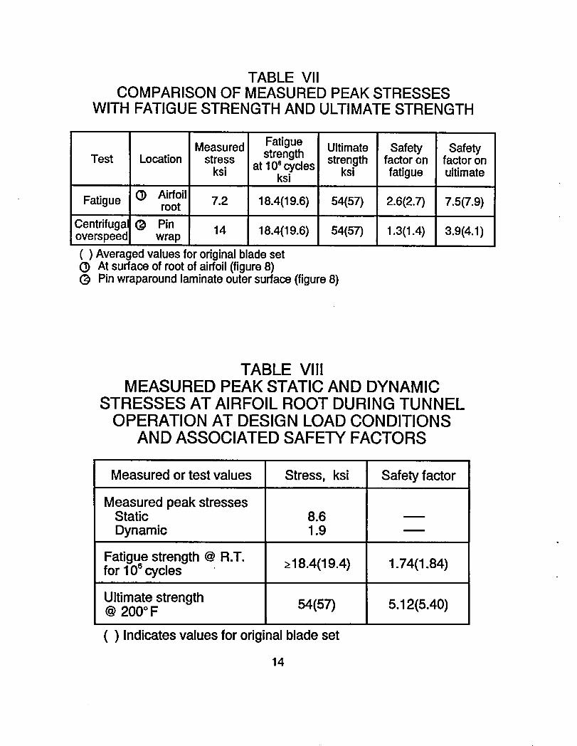
TABLE VIICOMPARISONOF MEASUREDPEAK STRESSES
WiTH FATIGUESTRENGTHAND ULTIMATESTRENGTH
Measured Fatigue Ultimate Safety SafetyTest Location stress strength strength factoron factoron
ksi at 106cycles ksi fatigue ultimateksi
Fatigue (]) Airfoil 7.2 18.4(19.6) 54(57) 2.6(2.7) 7.5(7.9)root
Centrifugal(_ Pin14 18.4(19.6) 54(57) 1.3(1.4) 3.9(4.1)overspeed wrap
( ) Averagedvaluesfor originalbladesetO At surfaceof rootof airfoil(figure8)(_ Pinwraparoundlaminateoutersurface(figure8)
TABLE VIIIMEASURED PEAK STATIC AND DYNAMIC
STRESSES AT AIRFOIL ROOT DURING TUNNELOPERATION AT DESIGN LOAD CONDITIONS
AND ASSOCIATED SAFETY FACTORS
Measuredor test values Stress, ksi Safetyfactor
MeasuredpeakstressesStatic 8.6Dynamic 1.9
[email protected]. >18.4(19.4) 1.74(1.84)for 106cycles
Ultimatestrength 54(57) 5.12(5.40)@200°F
( ) Indicatesvaluesfor originalbladeset
14
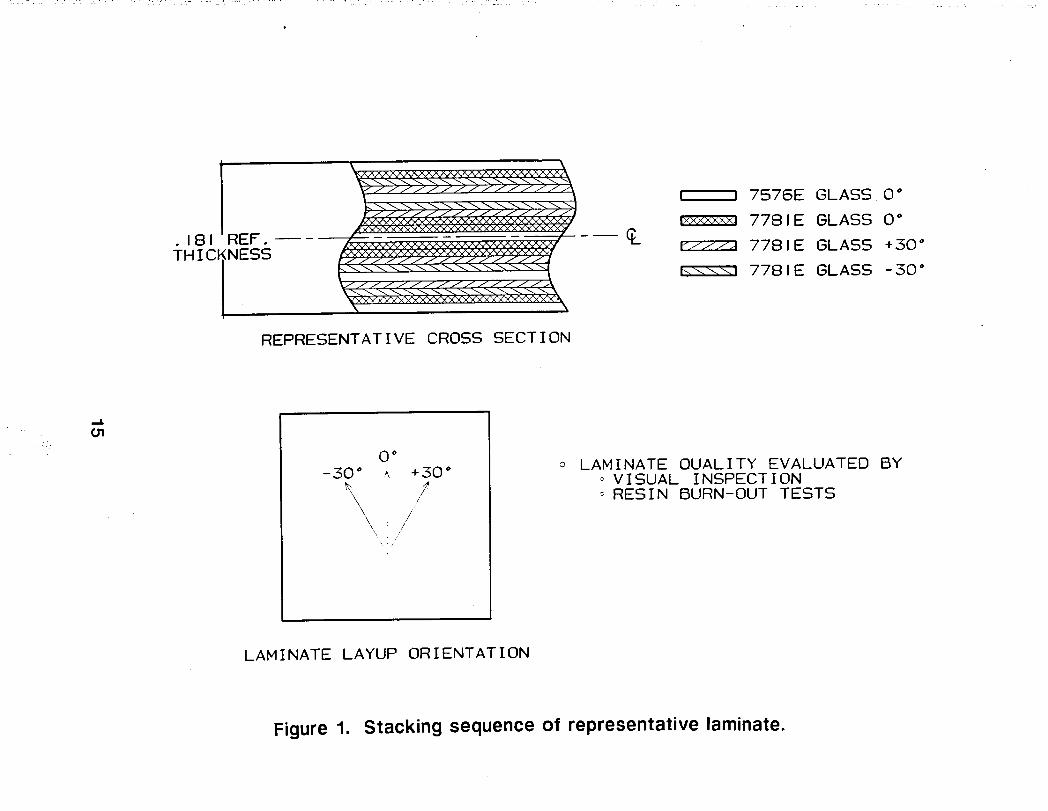
! I 7576E GLASS 0 °
v._xi 7781E GLASS 0 °
.181 REF. _ r///_ 7781E GLASS +30"
THICINESS
K_! 7781E GLASS -30 °
REPRESENTATIVE CROSS SECTION
0°__30 _ I_ +30 _ 0 LAMINATE OUALITY EVALUATED BY
/ ° VISUAL INSPECTION/ _ RESIN BURN-OUT TESTS
/'\ ; /\ z
LAMINATE LAYUP ORIENTATION
Figure 1. Stacking sequence of representative laminate.
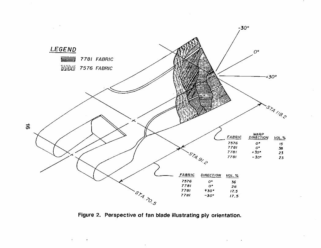
-30 °
LEGEND o"_ 7781 FABRIC
_-._ 75 76 FABRIC
•.30 °
,..g
WARPFA BRIC DIRECTION VOL. %
75 76 0" 157781 0 o 387 781 . 30 ° 23
7781 -30 o 23
FABRIC DIRECTION VOL. %
7576 0 o 367781 0 ° 28
7781 .30 ° 17.5
_'°_'_t 7781 -30 ° 17.5
Figure 2. Perspective of fan blade illustrating ply orientation.
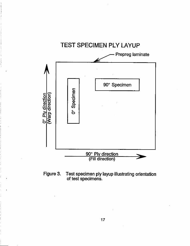
TESTSPECIMENPLYLAYUP
f Prepreglaminate
I 90° Specimen I
_' -_,i{
_>o. o t
_ _ ,./
[
90° Ply direction(Filldirection) f
Figure3. Testspecimenplylayupillustratingorientationof test specimens.
17
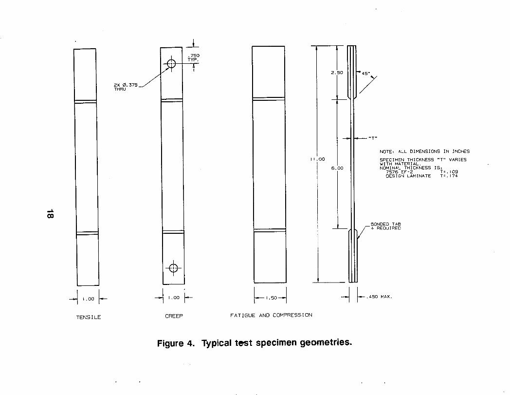
NOTE= ALL DIMENSIONS IN INCHES
I .00 SPECIMEN THICKNESS "T" VARIESWITH MATERIAL.
6.00 NOMINAL THICKNESS IS:7576 EF-2 T=,I09DESIGN LAMINATE T=,174
BONDED TABi__ REQUIRED
1.00 _ _ 1.00 .,I--- -.,I--- I.SO--," 4 F'450 MAX.
TENSILE CREEP FATIGUE AND COMPRESSION
Figure 4. Typical test specimen geometries.
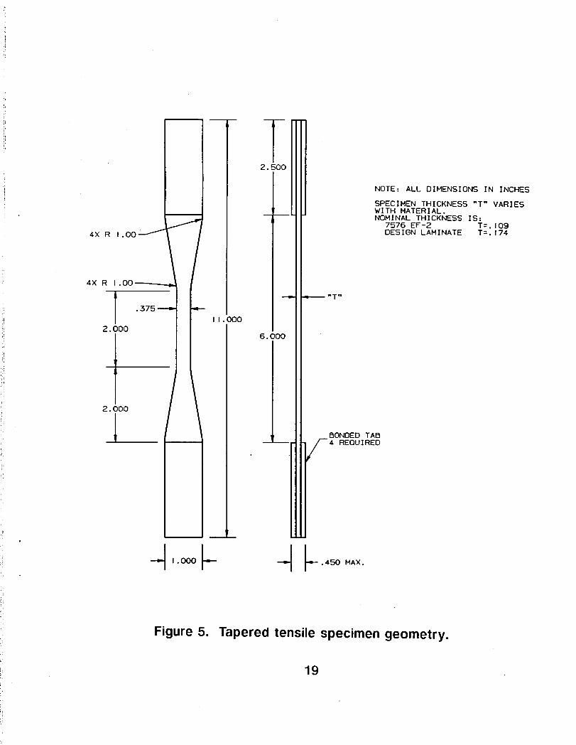
Tir
!,
2. 500
NOTE: ALL DIMENSIONS IN INCHES
SPECIMEN THICKNESS "T" VARIESWITH MATERIAL.NOMINAL THICKNESS IS:
7576 EF-2 T=.I094X R 1.00 _ DESIGN LAMINATE T=.174
"x°i°°-If _-_--'lT,,ooo
2. iO0 I 6. 000
1[/
,!
_ 2.i00 BONDED TAB-- REOUIRED
,P
;i --l,- 1.000 .,.I-- "-I" .450 MAX.
Figure5. Taperedtensilespecimengeometry.
19
SPECIMEN
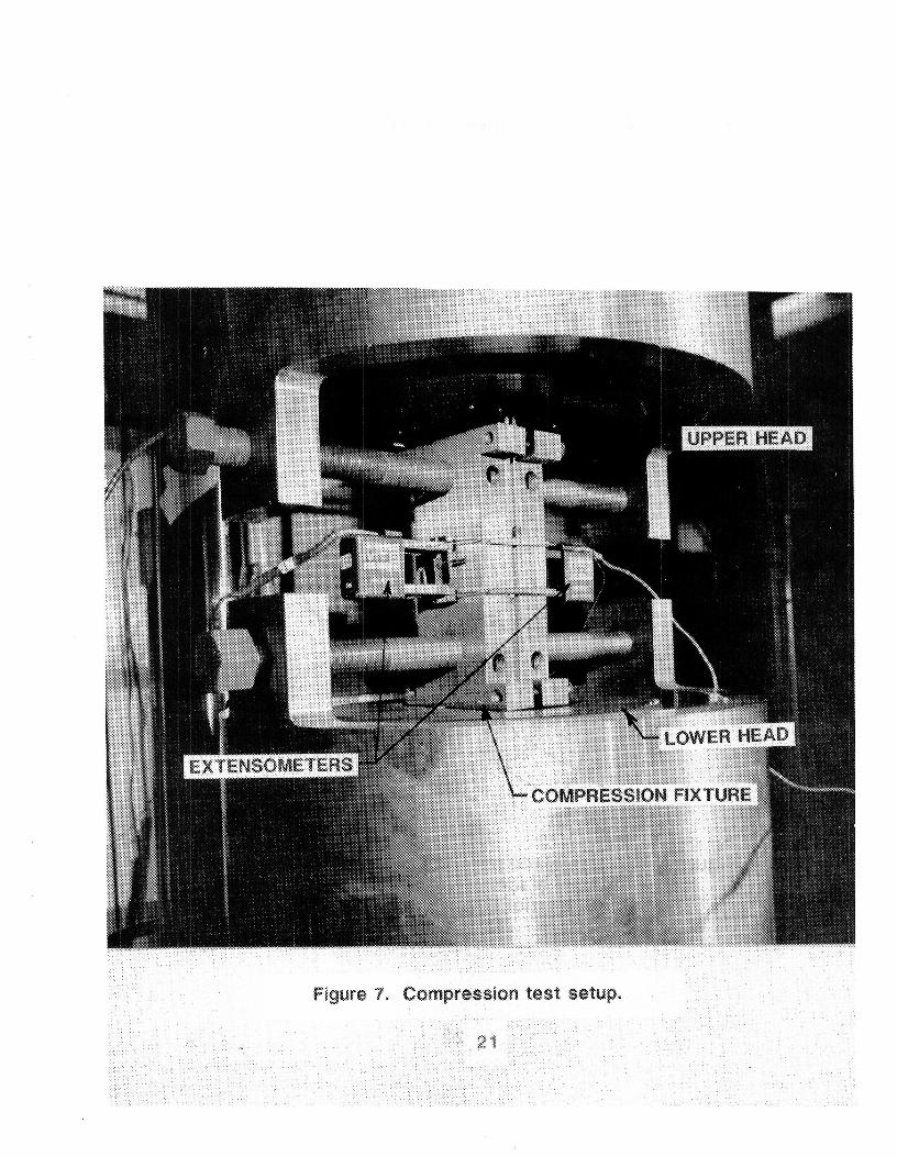
Figure 7_ Compressiontest setup°

NTF Fan Blade Assembly
Jf
JJ
j- Airfoil
Platform
Channel
Side Fairing
Figure 8. NTF fan blade assembly. Point 1 is at surfaceof root of blade, point 2 is pin wraparoundlaminate outer surface.
22

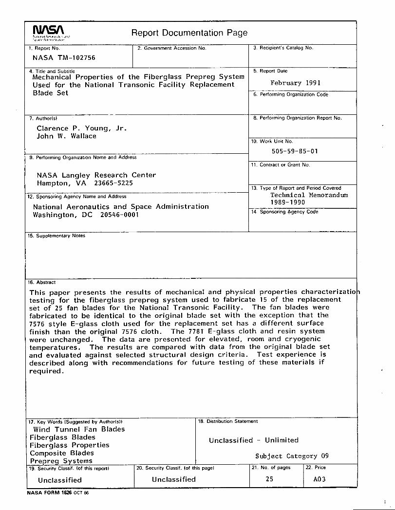
Report Documentation Page1. Report No. 2. Government Accession No. 3. Recipient's Catalog No.
NASA TM-102756
4. Title and Subtitle 5 Report Date
Mechanical Properties of the Fiberglass Prepreg SystemUsed for the National Transonic Facility Replacement February 1991
Blade Set 6. Performing Organization Code
7. Author(s) 8. Performing Organization Report No.
Clarence P. Young, Jr.John W. Wallace
10. Work Unit No.
505-59-85-019. Performing Organization Name and Address
11. Contract or Grant No.
NASA Langley Research CenterHampton, VA 23665-5225
13 Type of Report and Period Covered
12. Sponsoring Agency Name and Address Technical Memorandum1989-1990
National Aeronautics and Space AdministrationWashington, DC 20546-0001 14 Sponsoring Agency Code
15. Supplementary Notes
16. Abstract
This paper presents the results of mechanical and physical properties characterizatio:testing for the fiberglass prepreg system used to fabricate 15 of the replacementset of 25 fan blades for the National Transonic Facility. The fan blades werefabricated to be identical to the original blade set with the exception that the7576 style E-glass cloth used for the replacement set has a different surfacefinish than the original 7576 cloth. The 7781 E-glass cloth and resin systemwere unchanged. The data are presented for elevated, room and cryogenictemperatures. The results are compared with data from the original blade setand evaluated against selected structural design criteria. Test experience isdescribed along with recommendations for future testing of these materials ifrequired.
17. Key Words (Suggested by Author(s)) 18. Distribution Statement
Wind Tunnel Fan Blades
Fiberglass Blades Unclassified- UnlimitedFiberglass Properties
Composite Blades Subject Category 09Prepreg Systems
19. Security Classif. (of this report) 20. Security Classif. (of this pagel 21. No. of pages 22. Price
Unclassi fled Unclassified 25 A0 3
NASA FORM 1626 OCT 86
1