Embed Size (px)
Citation preview
NASA Technical Memorandum 83789
Photovoltaic Power System for SatelliteEarth Stations in Remote Areas: ProjectStatus and Design Description
Richard DeLombardLewis Research CenterCleveland, Ohio
Prepared for theInternational Telecommunications Energy Conferencesponsored by the Communications Society of the Institute of Electricaland Electronics EngineersNew Orleans, Louisiana, November 4-7, 1984
NASA
https://ntrs.nasa.gov/search.jsp?R=19840025571 2018-05-23T23:45:34+00:00Z
PHOTOVOLTAIC POWER SYSTEM FOR SATELLITE EARTH STATIONS IN REMOTE AREAS:
PROJECT STATUS AND DESIGN DESCRIPTION
N Richard DeLombardNational Aeronautics and Space Administration
Lewis Research CenterCleveland. Ohio 44135
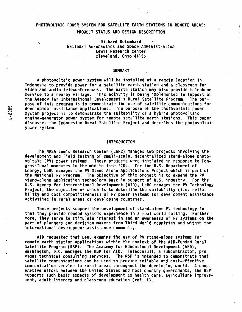
SUMMARY
A photovoltaic power system will be Installed at a remote location 1nIndonesia to provide power for a satellite earth station and a classroom forvideo and audio teleconferences. The earth station may also provide telephoneservice to a nearby village. This activity 1s being Implemented 1n support ofthe Agency for International Development's Rural Satellite Program. The pur-pose of this program 1s to demonstrate the use of satellite communications for
£ development assistance applications. The purpose of the photovoltaic power£i system project 1s to demonstrate the suitability of a hybrid photovoltaicui' engine-generator power system for remote satellite earth stations. This paper
discusses the Indonesian Rural Satellite Project and describes the photovoltaicpower system.
INTRODUCTION
The NASA Lewis Research Center (LeRC) manages two projects Involving thedevelopment and field testing of small-scale, decentralized stand-alone photo-voltaic (PV) power systems. These projects were Initiated 1n response to Con-gressional mandates 1n the mid to late '70s. For the U.S. Department ofEnergy, LeRC manages the PV Stand-Alone Applications Project which 1s part ofthe National PV Program. The objective of this project 1s to expand the PVstand-alone application technology base 1n support of U.S. Industry. For theU.S. Agency for International Development (AID), LeRC manages the PV TechnologyProject, the objective of which 1s to determine the suitability (I.e. relia-bility and cost-competitiveness) of PV power systems for development assistanceactivities 1n rural areas of developing countries.
These projects support the development of stand-alone PV technology 1nthat they provide needed systems experience 1n a real-world setting. Further-more, they serve to stimulate Interest 1n and an awareness of PV systems on thepart of planners and decision makers from Third World countries and within theInternational development assistance community.
AID requested that LeRC examine the use of PV stand-alone systems forremote earth station applications within the context of the AID-funded RuralSatellite Program (RSP). The Academy for Educational Development (AED),Washington, D.C. manages the RSP for AID. Teleconsult, a subcontractor, pro-vides technical consulting services. The RSP 1s Intended to demonstrate thatsatellite communications can be used to provide reliable and cost-effectivecommunication service to rural areas throughout the developing world. A coop-erative effort between the United States and host country governments, the RSPsupports such basic aspects of development as health care, agriculture Improve-ment, adult literacy and classroom education (ref. 1).
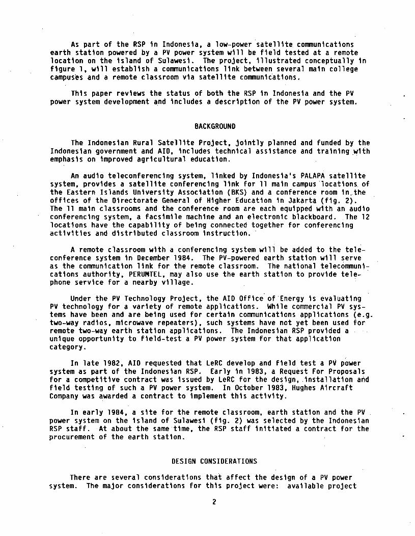
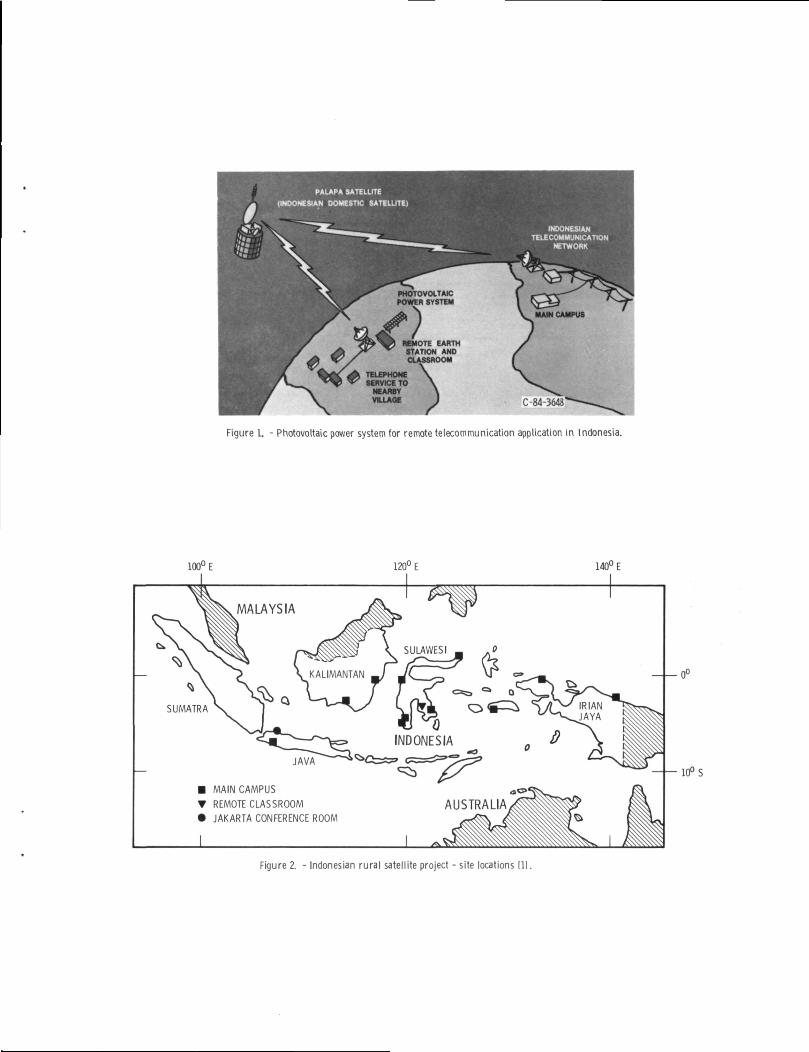
As part of the RSP 1n Indonesia, a low-power satellite communicationsearth station powered by a PV power system will be field tested at a remotelocation on the Island of Sulawesi. The project, Illustrated conceptually 1nfigure 1, will establish a communications link between several main collegecampuses and a remote classroom via satellite communications.
This paper reviews the status of both the RSP 1n Indonesia and the PVpower system development and Includes a description of the PV power system.
BACKGROUND
The Indonesian Rural Satellite Project, jointly planned and funded by theIndonesian government and AID, Includes technical assistance and training withemphasis on Improved agricultural education.
An audio teleconferencing system, linked by Indonesia's PALAPA satellitesystem, provides a satellite conferencing link for 11 main campus locations ofthe Eastern Islands University Association (BKS) and a conference room In.theoffices of the Directorate General of Higher Education 1n Jakarta (fig. 2).The 11 main classrooms and the conference room are each equipped with an audioconferencing system, a facsimile machine and an electronic blackboard. The 12locations have the capability of being connected together for conferencingactivities and distributed classroom Instruction.
A remote classroom with a conferencing system will be added to the tele-conference system 1n December 1984. The PV-powered earth station will serveas the communication link for the remote classroom. The national telecommuni-cations authority, PERUMTEL, may also use the earth station to provide tele-phone service for a nearby village.
Under the PV Technology Project, the AID Office of Energy 1s evaluatingPV technology for a variety of remote applications. While commercial PV sys-tems have been and are being used for certain communications applications (e.g.two-way radios, microwave repeaters), such systems have not yet been used forremote two-way earth station applications. The Indonesian RSP provided aunique opportunity to field-test a PV power system for that applicationcategory.
In late 1982, AID requested that LeRC develop and field test a PV powersystem as part of the Indonesian RSP. Early 1n 1983, a Request For Proposalsfor a competitive contract was Issued by LeRC for the design, Installation andfield testing of such a PV power system. In October 1983, Hughes AircraftCompany was awarded a contract to Implement this activity.
In early 1984, a site for the remote classroom, earth station and the PVpower system on the Island of Sulawesi (fig. 2) was selected by the IndonesianRSP staff. At about the same time, the RSP staff Initiated a contract for theprocurement of the earth station.
DESIGN CONSIDERATIONS
There are several considerations that affect the design of a PV powersystem. The major considerations for this project were: available project
funds, available solar energy (Insolation) data, site location, transporta-bility, load energy consumption, load power profile and power system outputcharacteristics.
Practically all earth stations that transmit and receive require somemeans of air conditioning. For a state-of-the-art earth station for use withdomestic satellites, the power and energy requirements for the air conditioningare often equivalent to that of the earth station Itself. For the IndonesianRSP, 1t was necessary to minimize the dally energy required by the earthstation to reduce the size of the photovoltaic array and battery. This was dueprimarily to budget constraints. AED, therefore. Included a requirement forlow operating power 1n the specifications for the earth station procurement.The operating power was reduced through the use of high-efficiency low-poweramplifiers, elimination of the air conditioner and turning off the earthstation and classroom loads during nonoperatlng hours.
The sizes of the PV array and the battery for a stand-alone photovoltaicsystem are normally based on the amount of sunlight available (Insolation) atthe planned Installation site, the electrical load requirements (power leveland dally profile) and the available funds. At the time of contract award toHughes, the precise site location was uncertain and only approximate valueswere known for -the load use pattern and load power requirements. The size ofthe PV array was, therefore, based on estimates of the Insolation and theapproximate load pattern, as well as funding limitations. The actual dallyenergy output of the PV array will depend on the actual Insolation character-istics of the Installation site. If there 1s a short-term deficit 1n the arrayenergy relative to the load energy, the battery will supply the requisiteenergy. For a long-term deficit, the engine-generator will supply the requi-site energy.
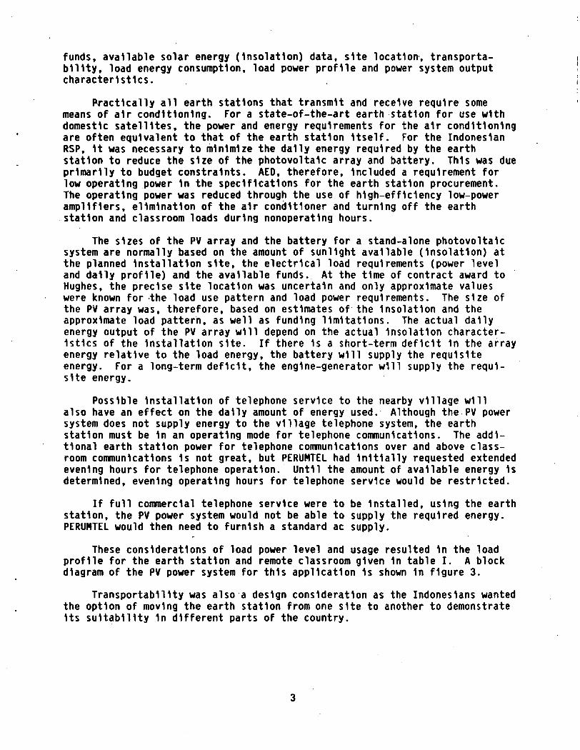
Possible Installation of telephone service to the nearby village willalso have an effect on the dally amount of energy used. Although the PV powersystem does not supply energy to the village telephone system, the earthstation must be 1n an operating mode for telephone communications. The addi-tional earth station power for telephone communications over and above class-room communications 1s not great, but PERUMTEL had Initially requested extendedevening hours for telephone operation. Until the amount of available energy 1sdetermined, evening operating hours for telephone service would be restricted.
If full commercial telephone service were to be Installed, using the earthstation, the PV power system would not be able to supply the required energy.PERUMTEL would then need to furnish a standard ac supply.
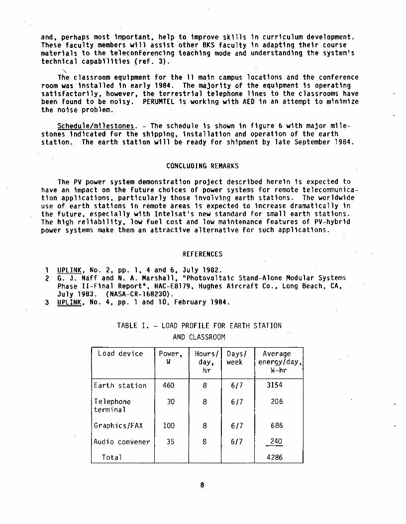
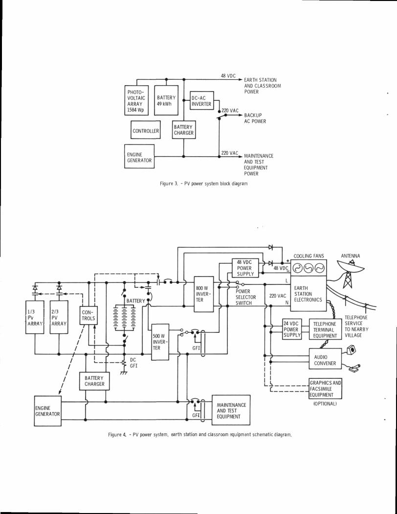
These considerations of load power level and usage resulted 1n the loadprofile for the earth station and remote classroom given 1n table I. A blockdiagram of the PV power system for this application 1s shown 1n figure 3.
Transportability was also a design consideration as the Indonesians wantedthe option of moving the earth station from one site to another to demonstrateIts suitability 1n different parts of the country.
SYSTEM DESCRIPTION
Load Requirements
Ttie load devices to be powered by the PV power system are shown schemat-ically 1n figure 4 and Include the earth station, an 800 W Inverter, telephoneterminal equipment, graphics equipment, facsimile machine and the audio con-vener. All of these load devices are supplied by the RSP. The power require-ments of the various load devices are shown 1n table I.
The 800 W Inverter was originally Intended to power only the earth station.The 500 W Inverter which 1s part of the PV power system was to power the class-room equipment. The available Increments of Inverter size from the supplierforced the choice of the 800 W Inverter to power the 460 W earth station. Toreduce the tare power lost 1n two operating Inverters, 1t was decided that theclassroom loads would also be powered from the 800 W Inverter. The 800 WInverter will also allow for the future expansion of the earth station for moretelephone channels.
The cooling fans for the earth station are powered by 48 V dc to reduce theamount of power passed through the Inverter with the attendant losses. In thebackup mode, when the engine-generator 1s furnishing power to the system, thefans operate from the fan power supply.
Basic Power System Design
General.- A cost plus fixed fee contract was awarded to Hughes onOctober 7, 1983 for the design, fabrication, Installation and one year opera-tional support of the PV power system. The task elements of this contract areoutlined 1n table II.
The system design proposed by Hughes was a slight modification of thatdeveloped by Hughes under a prior LeRC contract for a modular PV system design(ref. 2). One of the objectives of the previous contract was to develop ageneric PV system design suitable for nearly any location 1n the world. Theparticular requirements of the remote earth station application led to somemodifications of the previous standard design. Two major modifications arethe addition of the backup engine-generator and the Inverter.
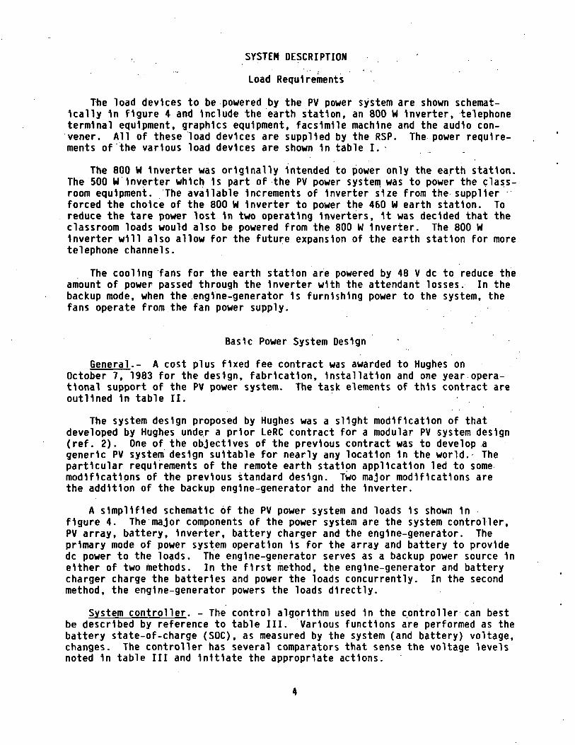
A simplified schematic of the PV power system and loads 1s shown 1nfigure 4. The major components of the power system are the system controller,PV array, battery, Inverter, battery charger and the engine-generator. Theprimary mode of power system operation 1s for the array and battery to providedc power to the loads. The engine-generator serves as a backup power source 1neither of two methods. In the first method, the engine-generator and batterycharger charge the batteries and power the loads concurrently. In the secondmethod, the engine-generator powers the loads directly.
System controller. - The control algorithm used 1n the controller can bestbe described by reference to table III. Various functions are performed as thebattery state-of-charge (SOC), as measured by the system (and battery) voltage,changes. The controller has several comparators that sense the voltage levelsnoted 1n table III and Initiate the appropriate actions.
Battery SOC control 1s performed by temporarily and successively switchingoff the two array sections at high levels of SOC or turning the engine-generator on at low levels of SOC. When the controller senses that the battery1s nearly at 100 percent SOC, 1t switches off the two sections of the array toreduce, the battery charging current. As the voltage decreases, the array sec-tions are switched on again. If the battery 1s at approximately 40 percentSOC, the controller Initiates the start of the engine-generator to charge thebatteries. During this method of engine-generator operation, the loads con-tinue to receive power through the 800 W Inverter.
The power system 1s designed to respond to two types of failures, nominallytermed "soft" and "hard." A "soft" failure occurs when the array electricalenergy output has not been sufficient to meet the load demands and to keep thebattery charged. The battery would then become discharged. The controllerwould automatically start the engine-generator to charge the battery throughthe battery charger. The controller would stop the engine-generator when thebattery reaches approximately 90 percent SOC. Since this type of failure wouldbe the most likely to occur, this 1s a no-break type of power backup.
A "hard" failure occurs when there has been a failure of a critical part ofthe power system and the system cannot supply any power to the loads. Theengine-generator would then have to be manually started and used to power theloads until the PV power system could be repaired and returned to service.Since this type of failure 1s less likely to occur, a break 1n service 1stolerated for this type of power backup.
Extreme over- and under-voltage system protection 1s also Included 1n thecontroller functions. An over-voltage condition results from overcharging thebattery due to a failure of the controller, engine-generator and/or batterycharger. In this case, the controller would disconnect the PV array andengine-generator from the battery. An under-voltage condition would generallybe caused by the lack of Insolation over a period of time, overuse of theloads, failure of the engine-generator to start, failure of the battery chargeror a combination of these causes. In this case, the controller would dis-connect the loads from the battery.
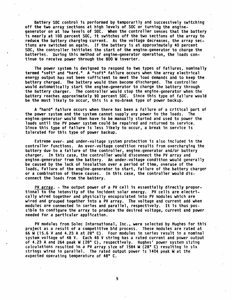
PV array. - The output power of a PV cell 1s essentially directly propor-tional to the Intensity of the Incident solar energy. PV cells are electri-cally wired together and physically encapsulated Into PV modules which arewired and grouped together Into a PV array. The voltage and current add whenmodules are connected 1n series and parallel, respectively. It 1s thus pos-sible to configure the array to produce the desired voltage, current and powerneeded for a particular application.
PV modules from Solec International, Inc., were selected by Hughes for thisproject as a result of a competitive bid process. These modules are rated at66 W (15.6 V and 4.23 A at 28° C). Four modules 1n series result 1n a nominalsystem voltage of 48 V. Each 48 V string has a rated current and power outputof 4.23 A and 264 peak W (28° C), respectively. Hughes' power system sizingcalculations resulted 1n a PV array size of 1584 W (28° C) resulting 1n sixstrings wired 1n parallel. The rated output power 1s 1404 peak W at theexpected operating temperature of 48° C.
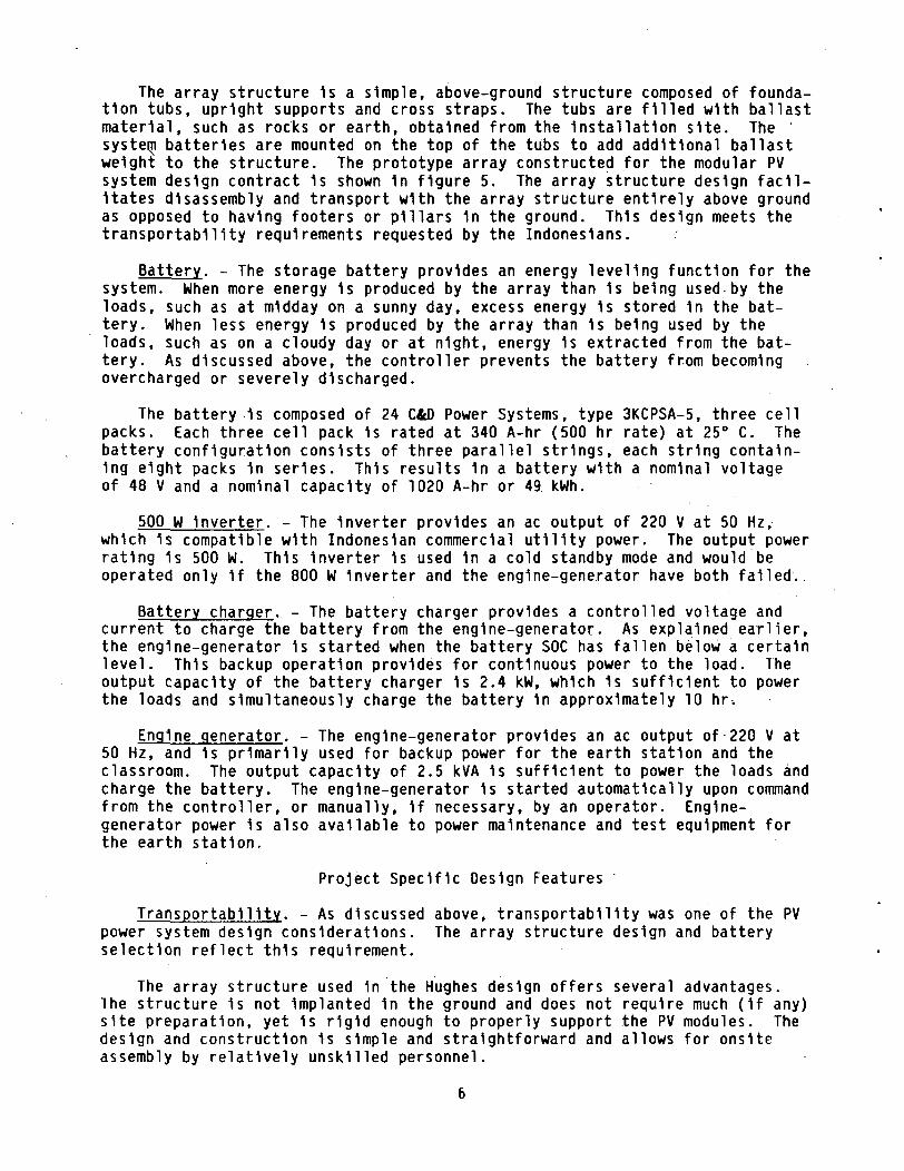
The array structure 1s a simple, above-ground structure composed of founda-tion tubs, upright supports and cross straps. The tubs are filled with ballastmaterial, such as rocks or earth, obtained from the Installation site. Thesystem batteries are mounted on the top of the tubs to add additional ballastweight to the structure. The prototype array constructed for the modular PVsystem design contract 1s shown 1n figure 5. The array structure design facil-itates disassembly and transport with the array structure entirely above groundas opposed to having footers or pillars 1n the ground. This design meets thetransportability requirements requested by the Indonesians.
Battery. - The storage battery provides an energy leveling function for thesystem. When more energy 1s produced by the array than 1s being used by theloads, such as at midday on a sunny day, excess energy 1s stored 1n the bat-tery. When less energy 1s produced by the array than 1s being used by theloads, such as on a cloudy day or at night, energy 1s extracted from the bat-tery. As discussed above, the controller prevents the battery from becomingovercharged or severely discharged.
The battery 1s composed of 24 C&D Power Systems, type 3KCPSA-5, three cellpacks. Each three cell pack 1s rated at 340 A-hr (500 hr rate) at 25° C. Thebattery configuration consists of three parallel strings, each string contain-ing eight packs 1n series. This results 1n a battery with a nominal voltageof 48 V and a nominal capacity of 1020 A-hr or 49. kWh.
500 W Inverter. - The Inverter provides an ac output of 220 V at 50 Hz,which 1s compatible with Indonesian commercial utility power. The output powerrating 1s 500 W. This Inverter 1s used 1n a cold standby mode and would beoperated only 1f the 800 W Inverter and the engine-generator have both failed.
Battery charger. - The battery charger provides a controlled voltage andcurrent to charge the battery from the engine-generator. As explained earlier,the engine-generator 1s started when the battery SOC has fallen below a certainlevel. This backup operation provides for continuous power to the load. Theoutput capacity of the battery charger 1s 2.4 kW, which 1s sufficient to powerthe loads and simultaneously charge the battery In approximately 10 hr.
Engine generator. - The engine-generator provides an ac output of 220 V at50 Hz, and 1s primarily used for backup power for the earth station and theclassroom. The output capacity of 2.5 kVA 1s sufficient to power the loads andcharge the battery. The engine-generator 1s started automatically upon commandfrom the controller, or manually, 1f necessary, by an operator. Engine-generator power 1s also available to power maintenance and test equipment forthe earth station.
Project Specific Design Features
Transportability. - As discussed above, transportability was one of the PVpower system design considerations. The array structure design and batteryselection reflect this requirement.
The array structure used 1n the Hughes design offers several advantages.The structure 1s not Implanted 1n the ground and does not require much (1f any)site preparation, yet 1s rigid enough to properly support the PV modules. Thedesign and construction 1s simple and straightforward and allows for onslteassembly by relatively unskilled personnel.
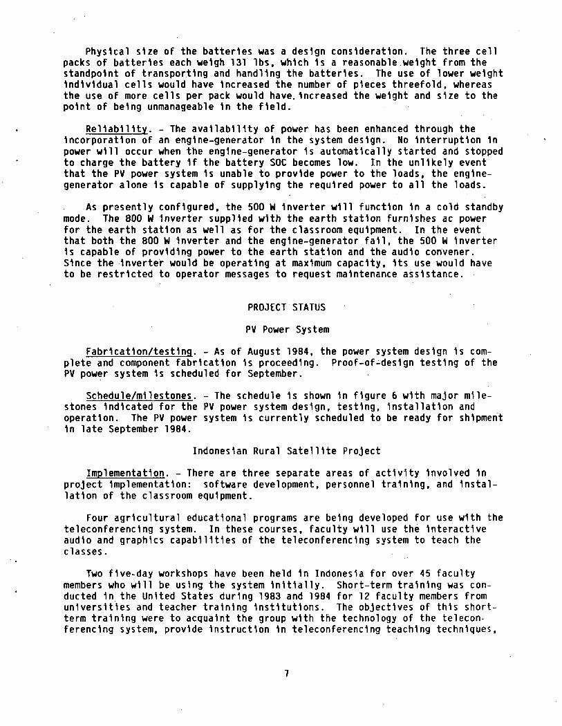
Physical size of the batteries was a design consideration. The three cellpacks of batteries each weigh 131 Ibs, which 1s a reasonable weight from thestandpoint of transporting and handling the batteries. The use of lower weightIndividual cells would have Increased the number of pieces threefold, whereasthe use of more cells per pack would have.Increased the weight and size to thepoint of being unmanageable 1n the field.
Reliability. - The availability of power has been enhanced through theIncorporation of an engine-generator 1n the system design. No Interruption 1npower will occur when the engine-generator 1s automatically started and stoppedto charge the battery 1f the battery SOC becomes low. In the unlikely eventthat the PV power system 1s unable to provide power to the loads, the engine-generator alone 1s capable of supplying the required power to all the loads.
As presently configured, the 500 W Inverter will function 1n a cold standbymode. The 800 W Inverter supplied with the earth station furnishes ac powerfor the earth station as well as for the classroom equipment. In the eventthat both the 800 W Inverter and the engine-generator fall, the 500 W Inverter1s capable of providing power to the earth station and the audio convener.Since the Inverter would be operating at maximum capacity. Its use would haveto be restricted to operator messages to request maintenance assistance.
PROJECT STATUS
PV Power System
Fabrication/testing. - As of August 1984, the power system design 1s com-plete and component fabrication 1s proceeding. Proof-of-des1gn testing of thePV power system 1s scheduled for September.
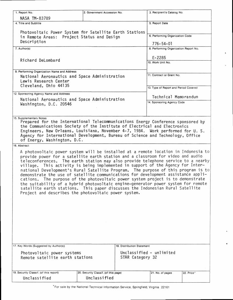
Schedule/mllestones. - The schedule 1s shown 1n figure 6 with major mile-stones Indicated for the PV power system design, testing, Installation andoperation. The PV power system 1s currently scheduled to be ready for shipment1n late September 1984.
Indonesian Rural Satellite Project
Implementation. - There are three separate areas of activity Involved 1nproject Implementation: software development, personnel training, and Instal-lation of the classroom equipment.
Four agricultural educational programs are being developed for use with theteleconferencing system. In these courses, faculty will use the* Interactiveaudio and graphics capabilities of the teleconferencing system to teach theclasses.
Two five-day workshops have been held 1n Indonesia for over 45 facultymembers who will be using the system Initially. Short-term training was con-ducted 1n the United States during 1983 and 1984 for 12 faculty members fromuniversities and teacher training Institutions. The objectives of this short-term training were to acquaint the group with the technology of the telecon-ferencing system, provide Instruction 1n teleconferencing teaching techniques,
and, perhaps most Important, help to Improve skills 1n curriculum development.These faculty members will assist other BKS faculty 1n adapting their coursematerials to the teleconferencing teaching mode and understanding the system'stechnical capabilities (ref. 3).
\The classroom equipment for the 11 main campus locations and the conference
room was Installed In early 1984. The majority of the equipment 1s operatingsatisfactorily, however, the terrestrial telephone lines to the classrooms havebeen found to be noisy. PERUMTEL 1s working with AED 1n an attempt to minimizethe noise problem.
Schedule/milestones. - The schedule 1s shown 1n figure 6 with major mile-stones Indicated for the shipping. Installation and operation of the earthstation. The earth station will be ready for shipment by late September 1984.
CONCLUDING REMARKS
The PV power system demonstration project described herein 1s expected tohave an Impact on the future choices of power systems for remote telecommunica-tion applications, particularly those Involving earth stations. The worldwideuse of earth stations 1n remote areas 1s expected to Increase dramatically 1nthe future, especially with Intelsat's new standard for small earth stations.The high reliability, low fuel cost and low maintenance features of PV-hybr1dpower systems make them an attractive alternative for such applications.
REFERENCES
1 UPLINK. No. 2, pp. 1, 4 and 6, July 1982.2 G. J. Naff and N. A. Marshall, "Photovoltaic Stand-Alone Modular Systems
Phase II-F1nal Report", HAC-E8179, Hughes Aircraft Co., Long Beach, CA,July 1983. (NASA-CR-168230).
3 UPLINK. No. 4, pp. 1 and 10, February 1984.
TABLE I. - LOAD PROFILE FOR EARTH STATION
AND CLASSROOM
Load device
Earth station
Telephoneterminal
Graphics/FAX
Audio convener
Total
Power,W
460
30
100
35
Hours/day,hr
8
8
8
8
Days/week
6/7
6/7
6/7
6/7
Averageenergy/day,
W-hr
3154
206
686
240
4286
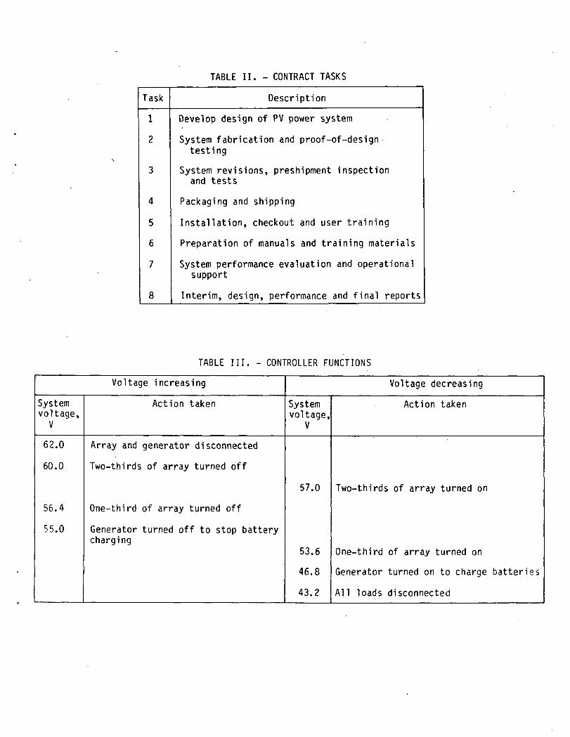
TABLE II. - CONTRACT TASKS
Task Description
1
2
4
5
6
7
Develop design of PV power system
System fabrication and proof-of-designtesting
System revisions, preshipment inspectionand tests
Packaging and shipping
Installation, checkout and user training
Preparation of manuals and training materials
System performance evaluation and operationalsupport
Interim, design, performance and final reports
TABLE III. - CONTROLLER FUNCTIONS
Voltage increasing Voltage decreasing
Systemvoltage,
V
Action taken Systemvoltage,
V
Action taken
62.0
60.0.
56.4
55.0
Array and generator disconnected
Two-thirds of array turned off
One-third of array turned off
Generator turned off to stop batterycharging
57.0 Two-thirds of array turned on
53.6
46.8
43.2
One-third of array turned on
Generator turned on to charge batteries
All loads disconnected
C-84-3643
Figure 1. - Photovoltaic power system for remote telecommunication application in Indonesia.
100° E 120° E 140° E
• MAIN CAMPUS
T REMOTE CLASSROOM
• JAKARTA CONFERENCE ROOM
10° S
Figure 2. - Indonesian rural satellite project - site locations 111.
48VDCEARTH STATIONAND CLASSROOMPOWER
BACKUPAC POWER
MAINTENANCEAND TESTEQUIPMENTPOWER
Figure 3. - PV power system block diagram
ANTENNA
TELEPHONESERVICETO NEARBYVILLAGE
GRAPHICS ANDFACSIMILEEQUIPMENT
(OPT ION A LI
Figure 4. - PV power system, earth station and classroom equipment schematic diagram.
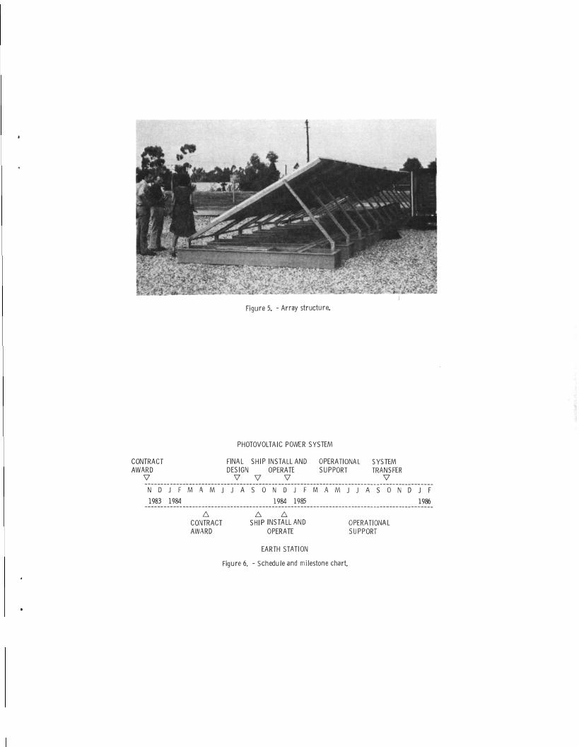
Figure 5. - Array structure.
PHOTOVOLTAIC POWER SYSTEM
CONTRACTAWARD
V
N D J F
1983 1984
M A M J
ACONTRACTAWARD
FINAL SHIP INSTALL ANDDESIGN OPERATE
V V V
J A S 0 N D J F
1984 1985
A ASHIP INSTALL AND
OPERATE
OPERATIONAL SYSTEMSUPPORT TRANSFER
V
M A M J J A S O N D
OPERATIONALSUPPORT
J F
1986
EARTH STATION
Figure 6. - Schedule and milestone chart
1. Report No.
NASA TM-83789
2. Government Accession No. 3. Recipient's Catalog No.
4. Title and Subtitle 5. Report Date
Photovoltaic Power System for Satellite Earth Stationsin Remote Areas: Project Status and DesignDescription
6. Performing Organization Code
776-54-017. Author(s)
Richard DeLombard
B. Performing Organization Report No.
E-228510. Work Unit No.
9. Performing Organization Name and Address
National Aeronautics and Space AdministrationLewis Research CenterCleveland, Ohio 44135
11. Contract or Grant No.
12. Sponsoring Agency Name and Address
National Aeronautics and Space AdministrationWashington, D.C. 20546
13. Type of Report and Period Covered
Technical Memorandum14. Sponsoring Agency Code
15. Supplementary NotesPrepared for the International Telecommunications Energy Conference sponsored bythe Communications Society of the Institute of Electrical and ElectronicsEngineers, New Orleans, Louisiana, November 4-7, 1984. Work performed for U. S.Agency for International Development, Bureau of Science and Technology, Officeof Energy, Washington, D.C.
16. Abstract
A photovoltaic power system will be installed at a remote location in Indonesia toprovide power for a satellite earth station and a classroom for video and audioteleconferences. The earth station may also provide telephone service to a nearbyvillage. This activity is being implemented in support of the Agency for Inter-national Development's Rural Satellite Program. The purpose of this program is todemonstrate the use of satellite communications for development assistance appli-cations. The purpose of the photovoltaic power system project is to demonstratethe suitability of a hybrid photovoltaic engine-generator power system for remotesatellite earth stations. This paper discusses the Indonesian Rural SatelliteProject and describes the photovoltaic power system.
17. Key Words (Suggested by Author(s))
Photovoltaic power systemsRemote satellite earth stations
19. Security Classif. (of this report)
Unclassified
16. Distribution Statement
UnclassifiedSTAR Category
20. Security Classif. (of this page)
Unclassified
- unlimited32
21. No. of pages 22 Price"
'For sale by the National Technical Information Service, Springfield. Virginia 22161
National Aeronautics andSpace Administration
Washington, D.C.20546
Official Business
Penalty for Private Use, $3OO
SPECIAL FOURTH CLASS MAILBOOK
Postage and Fees PaidNational Aeronautics andSpace AdministrationNASA-451 '
NASA POSTMASTER: If Undelrverahle (S<-riion I SKPostal Manual) IV. Nut Return