Embed Size (px)
Citation preview
VOLUME I
SUMMARY REPORT:
STUDY OF THE APPLICATION OF
HYDROGEN FUEL TO LONG-RANGE
SUBSONIC TRANSPORT AIRCRAFT
NASA CR-132558
by G. D. Brewer & R. E. MorrisR. H. Lange & J. W. Moore
JANUARY 1975
Prepared under Contract NAS 1-12972
for
LANGLEY RESEARCH CENTER
NATIONAL AERONAUTICS AND
SPACE ADMINISTRATION
byLOCKHEED-CALl FORNIA COMPANY
AND
LOCKHEED-GEORGIA COMPANY
__--.-. DIVISIONS OF LOCKHEED AIRCRAFT CORPORATIONe
|,
1. REPORT NO. 2. GOVERNMENT ACCESSION NO.
NASA CR-132558 .
4.T,TLE AND SUBTITLE VOLUME I
SUMMARY REPORT: Study of the Application of
Hydrogen Fuel to Long Range Subsonic TransportA_rcragt ........
7. AUTHOR(SI
Brewer. G.D. and Morris, R.E.;
Lange, Moore,R.H. and J.W. .,.", , , , |
9. PERFORMING ORGANIZATION NAME AND ADDRESS
LOCI<HEED-CALl FORNIA COMPANY LOCKHEED-GEORGIA CO.P.O. BOX 551 AND
BURBANK, CALIFORNIA 91520 MARIETTA, GEORGIA 30063
!12. SPONSORING AGENCY NAME AND ADDRESS
National Aeronautics and Space Administration
Langley Research Center
Hampton I Virgini_ 23665 .,15. SUPPLEMENTARY NOTES
3. RECIPIENT'S CATALOG NO.
5. REPOt_T DATE
Januar_ 1975el PERFORMING ORG CODE
8. PERFORMINGORG REPOF_T NO.
LR-26Z52-1
10. WORK U_IT NO.
11. CONTRACT OR GRANT N().
NAS 1-12972
13. TYPE OF REPORT AND PERIODCOVERED Contractor Fin_R_nort : Feb-Oct. 1974
14. SPONSORINGAGENCY CODE
16. ABSTRACT
This study was performed to investigate the feasibility, practicability,
and potential advantages/dlsadvantages of using liquid hydrogen as fuel in
long range, subsonic trs_nsport aircraft of advanced design. Both passenger
and cargo-type aircraft were investigated. To provide a valid basis for
comparison, conventional hydrocarbon (Jet A) fueled aircraft were designed
to perform identical missions using the same advanced technology and meeting
the same operational constraints.
The liquid hydrogen and Jet A fueled aircraft were compared on the basis
of weight, size, energy utilization, cost, noise, emissions, safety, and
operational characteristics. A program of technology development was
formulated.
17, KEY WORDS(SUGGESTED BY AUTHOR(S))
hydrogen, subsonic transport air-
craft, Jet A, cryogenic insulation,
alternate fuel, exhaust emissions,
noise, safety, energy utilization
19. SECURITY CLASSiF. 20.'SECURITY CLASSIF. (OF THIS PAGE)(OF THIS REPORT)
Unclassified Unclassified
18. DISTRIBUTION STATEMENT
21. NO. OF PAGES;22, "I_RICE"
}_8
FOREWORD •
Volume I is a summary of the "Study of the Application of Hydrogen Fuel to
Long Range Subsonic Transport Aircraft." The work was performed under Contract
NAS 1-12972 for NASA-Langley Research Center, Hampton, Virginia, during the nine
month period, February through October 1974. This summary report outlines the
methodology, presents the results and conclusions, and lists items recommended
for further investigation and development. Details of the study are presented in
Volume II, the contract final report, NASA CR-132559 dated January 1975.
The work was divided according to vehicle category: (i) passenger/cargo mis-
sion aircraft; and (2) all-cargo mission aircraft. The study was performed by the
Advanced Design organizations of the Lockheed-California Company, Burbank (passenger/
cargo missions), and the Lockheed-Georgia Company, Marietta (cargo-missions). Prime
responsibility for contract execution rested with the California Company under the
direction of G. Daniel Brewer as study manager. Robert E. Morris was project engi-
neer for passenger aircraft. Deputy study manager for cargo mission aircraft
analysis was R. H. Lange in Georgia. J. W. Moore served as project engineer for
cargo aircraft.
Mr. C. T. D'Aiutolo of the Aeronautical Systems Division of NASA-Langley
Research Center, was the technical monitor for the contract.
iii
SUMMARY
This study examinedthe feasibility of using liquid hydrogen as fuel in
advanced designs of long range, subsonic transport aircraft, and assessed the
potential advantages. Both passenger and cargo-type aircraft were investigated.
Passenger aircraft were designed to perform all combinations of the following
matrix of primary mission requirements:
PAYLOAD 36,300 kg (88,000 Ib) = h00 Passengers + cargo
RANGES 5,560 km (3,000 nmi) and 10,190 km (5,500 nmi)
CRUISESPEEDSMach0.80, 0.85, and 0.90
In addition, 600 and 800 passenger capacity aircraft were designed for Mach0.85 cruise
speed and for both ranges.
Cargo aircraft designs were studied to perform the following missions:
PAYLOAD
RANGE
CRUISESPEED
Mission i
56,700 kg (125,000 ib)
5,56o km (3,000 nmi)
Mach 0.85
Mission 2
ll3,h00 kg (250,000 lb)
lO,190 kg (5,500 nmi)
Math 0.85
To serve as a basis for comparison, reference aircraft fueled with conventional
hydrocarbon (Jet A) were designed to identical ground rules and for the same
missions, except that the passenger airplane requirements were limited to only
one speed, Mach 0.85.
Due to the low density, high energy content, and cryogenic temperature of
liquid hydrogen (LH 2) it was anticipated that optimum designs of LH 2 fueled air-
craft might require unusual design configurations to gain maximum advantage from its
use. This was found not to be the case. Although many unusual configurations were
explored, the designs of LH 2 fueled aircraft selected as preferred configurations
for both the passenger and cargo applications are conventional in appearance. Unusual
design concepts which were investigated proved to be inferior.
In every case the hydrogen fueled aircraft, which were selected using minimum
direct operating cost as the primary criterion, were found to be lighter, quieter,
able to operate from shorter runways, require smaller engines, minimize pollution
of the environment, and expend less energy in performing their design missions,
relative to equivalent designs fueled with Jet A. In addition, the hydrogen air-
craft are physically smaller in span, height, and wing area, but have larger
fuselages.'
The purchase price estimated for the LH2 aircraft was somewhathigher thanthat of the reference designs. This was due to a high va_ue accorded the hydrogen-
peculiar items, for which there is insufficient data to establish a truly meaningfulcost basis.
Direct operating costs of the hydrogen aircraft are significantly lower than
that of their Jet A fueled counterparts if the fuels cost the sameper unit of energy.
An evaluation of operations, maintenance, and safety aspects of the hydrogen
fueled aircraft revealed no significant features that would seriously affect
airline-type turn-around schedules, comparedto current practice with Jet A fuel.
Equipment to perform operations like refueling will be different, but neither the
numberof personnel involved nor the elapsed time required should be adverselyaffected.
The examination of larger payloads (600 and 800 passengers) indicated an
increasing flight efficiency for the larger aircraft. As payload increased, both
direct operating cost and block fuel fraction (expressed as a percentage of gross
weight) decreased.
vl
TABLEOFCONTENTS
Section
i
2
3
31
31.i
31.2
31.3
32
32.1
32.2
3.2.3
3.3
3.3.1
3.3.2
3.3.3
3.3.4
4
5
REFERENCES
FOREWORD
SUMMARY
INTRODUCTION
STUDY SCOPE
STUDY RESULTS
HYDROGEN RELATED TECHNOLOGY
Fuel System
Tank and Insulation System
Engines
PASSENGER AIRCRAFT
Configuration Concepts
Benefits Evaluation
Effect of Larger Payloads
CARGO AIRCRAFT
Configuration Concepts
Analysis of LH 2 Aircraft Designs
Reference (Jet A) Cargo Aircraft
Benefits Evaluation
RESEARCH AND TECHNOLOGY RECOMMEndATIONS
CONCLUSIONS
Page
iii
v
I
3
7
7
7
9
io
13
13
19
27
29
29
30
35
39
45
46
47
vii
LIST OF ILLUSTRATIONS
Figure
i
2
3
4
5
6
7
8
9
i0
ii
12
13
14
15
16
Title
Hydrogen Fuel System Elements
Economic Selection of Insulation Thickness
Cruise Performance of Turbofan Engines
Candidate Configurations of LH 2 Passenger Aircraft
LH 2 Passenger Aircraft - Internal Tank Configuration
LH 2 Passenger Aircraft - External Tank Configuration
Jet A Passenger Aircraft - General Arrangement
Direct Operating Cost of Fuels (Passenger Aircraft)
Effect of Larger Payloads on Passenger Aircraft
Characteristics (3000 nmi)
Effect of Larger Payloads on Passenger Aircraft
Characteristics (5500 nmi)
Candidate Cargo Aircraft Configuration Concepts
General Arrangement - Nose Loader Cargo Aircraft
General Arrangement - Swing Tail Cargo Aircraft
General Arrangement - Jet A Fueled Cargo Transport Aircraft
Direct Operating Cost vs Cost of Fuels (Cargo Aircraft)
Technology Development Program
Page
8
ii
12
14
15
15
22
24
28
28
29
31
33
38
$3
_5
iX'
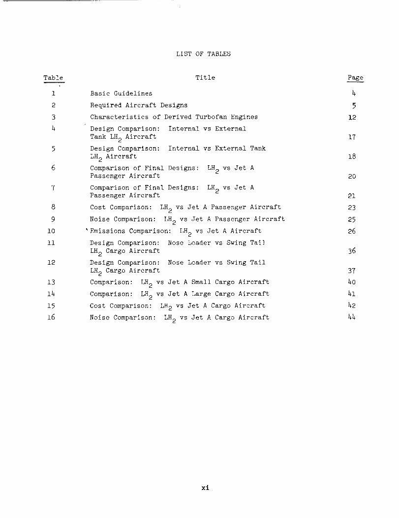
LIST OFTABLES
Table
i
2
3
4
8
9
i0
ii
12
13
14
15
16
Title
Basic Guidelines
Required Aircraft Designs
Characteristics of Derived Turbofan Engines
Design Comparison: Internal vs External
Tank LH 2 Aircraft
Design Comparison: Internal vs External Tank
LH 2 Aircraft
Comparison of Final Designs: LH 2 vs Jet APassenger Aircraft
Comparison of Final Designs: LH 2 vs Jet APassenger Aircraft
Cost Comparison: LH 2 vs Jet A Passenger Aircraft
Noise Comparison: LH 2 vs Jet A Passenger Aircraft
Emissions Comparison: LH 2 vs Jet A Aircraft
Design Comparison: Nose Loader vs Swing Tail
LH 2 Cargo Aircraft
Design Comparison: Nose Loader vs Swing Tail
LH 2 Cargo Aircraft
Comparison: LH 2 vs Jet A Small Cargo Aircraft
Comparison: LH 2 vs Jet A Large Cargo Aircraft
Cost Comparison: LH 2 vs Jet A Cargo Aircraft
Noise Comparison: LH 2 vs Jet A Cargo Aircraft
Page
4
5
12
17
18
2O
21
23
25
26
36
37
40
41
42
44
xl
1.0 INTRODUCTION
Growing concern for the problem of providing adequate supplies of petroleum-
derived fuels to meet U.S. demand,and recognition of the inevitable price that
must be paid for our ever increasing dependenceon foreign supplies, has led the
NASAto a broad study effort to review energy trends and to evaluate the possibiliities of alternate fuels for transport aircraft. The availability and cost of
petroleum-derived fuel for commercial transport aircraft will continue to become
less and less attractive in coming years. Shortages will continue to develop in thefuture, both because of international political and economicpressures, and as a
result of depletion of natural resources. Ultimately, and it is simply a question
of "how soon," rather than "if," an alternate fuel must be developed.
It is generally agreed that the alternate fuel will be either synthetic kerosene,
manufactured from coal, oil shale, or tar sands, or it will be liquid hydrogen.
Hydrogencan be madefrom a combination of coal and water, or from water alone, using
any of several processes and a wide variety of possible energy sources. The choicebetween synthetic kerosene and liquid hydrogen will be madebased on considerations
of cost, emissions, energy, noise, practicability, and long range world-wideavailability. The present study was performed to:
• Assess the feasibility and potential advantages of using liquid
hydrogen (LH 2) as fuel in long range, subsonic transport aircraft
(both passenger and cargo types).
• Identify the problems and technology requirements peculiar to such
aircraft.
• Outline a program for development of necessary technology on a timely
basis.

2.0 STUDYSCOPE
Advanceddesign transport aircraft were studied for both passenger and cargo-
carrying missions. Guidelines for the study are listed in Table i. The matrix of
design requirements for the aircraft is shownin Table 2. To provide a basis for
a val_d comparison of physical, performance, and economicparameters of the LH2-fueled designs with conventionally fueled aircraft, reference passenger transport
designs using Jet A fuel were established for one cruise speed (Mach0.85), 400 pas-
senger capacity, and for both ranges. In addition, Jet A-fueled reference aircraft
were designed for both of the cargo missions. Special care was taken to assure that
the reference aircraft were designed to the samestandards as the aircraft they were
to be comparedwith in each case.
All passenger aircraft were designed and evaluated at Lockheed-California
Companyand all cargo aircraft at Lockheed-Georgia Company. A large numberof
candidate aircraft configurations of both types were conceived and subjected to a
critical qualitative evaluation. The two configurations given the highest ratings
for each type of payload were selected for more detailed study and analysis.
Design studies were conducted to determine appropriate characteristics forthe hydrogen-related systems required on board the aircraft. These studies included
consideration of material, structural, and thermodynamicrequirements of the cryogenic
fuel tanks, their structural support systems, thermal protection systems, and for
the fuel system. Operations and maintenance procedures and requirements were con-
sidered in the design of these componentsand systems.
Computerdecks were generated to parametrically represent the performance,
size, and weight of advanced design, quiet turbofan engines using technology fore-
cast to be available after 1985, consistent with initial aircraft operational
capability in 1990-95. Decks were generated for engines designed for both fuels,
liquid hydrogen (LH2) and Jet A.
Similarly, aerodynamic, weight and cost data were generated in parametricform to represent use of advancedtechnolgies.
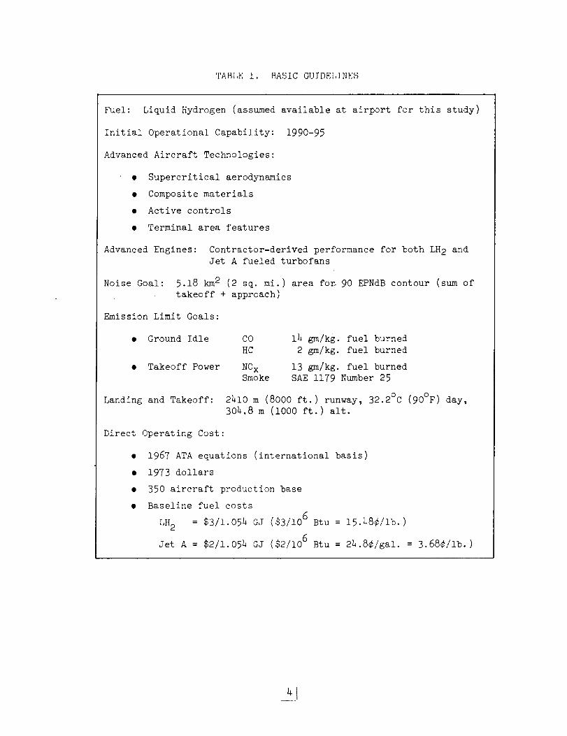
TABLEi. BASICGUIDELINES
Fuel: Liquid Hydrogen (assumedavailable at airport for this study)
Initial Operational Capability: 1990-95
AdvancedAircraft Technologies:
• Supercritical aerodynamics
• Compositematerials• Active controls
• Terminal area features
AdvancedEngines: Contractor-derived performance for both LH2 andJet A fueled turbofans
Noise Goal: 5.18 km2 (2 sq. mi.) area rod 90 EPNdBcontour (sumoftakeoff + approach)
Emission Limit Goals:
• Ground Idle
• Takeoff Power
Landing and Takeoff:
CO 14 gm/kg, fuel burnedHC 2 gm/kg, fuel burned
NOx 13 gm/kg, fuel burnedSmoke SAE1179 Number25
2410 m (8000 ft.) runway, 32.2°C (90°F) day,304.8 m (i000 ft.) alt.
Direct Operating Cost:
• 1967 ATAequations (international basis)
• 1973 dollars
• 350 aircraft production base• Baseline fuel costs
LH2 = $3/1.054 SJ ($3/106 Btu = 15.48¢/ib.)
Jet A = $2/1.054 GJ ($2/106 Btu = 24.8¢/ga!. = 3.68¢/ib.)
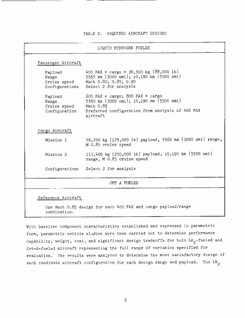
TABLE2. REQUIREDAIRCRAFTDESIGNS
LIQUIDHYDROGENFUELED
Passenger Aircraft
Payload
Range
Cruise speed
Configurations
Payload
Range
Cruise speed
Configuration
400 PAX + cargo = 36,300 kg (88,000 ib)
5560 km (3000 nmi); I0,190 km (5500 nmi)
Mach 0.80; 0.85; 0.90
Select 2 for analysis
600 PAX + cargo; 800 PAX + cargo
556o km (3OOO nmi); i0,190 km (5500 nmi)
Mach 0.85
Preferred configuration from analysis of 400 PAX
aircraft
Car_o Aircraft
Mission i
Mission 2
Configurat ions
56,700 kg (125,000 Ib) payload, 5560 km (3000 nmi) range,
M 0.85 cruise speed
113,200 kg (250,000 ib) payload, 10,190 km (5500 nmi)
range, M 0.85 cruise speed
Select 2 for analysis
JET A FUELED
Reference Aircraft
One Mach 0.85 design for each 400 PAX and cargo payload/range
combination.
With baseline component characteristics established and expressed in parametric
form, parametric vehicle studies were then carried out to determine performance
capability, weight, cost, and significant design tradeoffs for both LH2-fueled and
Jet-A-fueled aircraft representing the full range of variables specified for
evaluation. The results were analyzed to determine the most satisfactory design of
each candidate aircraft configuration for each design range and payload. The LH 2
5
fueled aircraft designs thus selected were then compared with each other for the
purpose of choosing a preferred configuration. After additional design refinement
the selected LH 2 configuration was then critically compared with the reference
(Jet A) aircraft in a "benefits evaluation."
The characteristics of LH 2 fueled passenger aircraft sized to carry larger
payloads were also determimed. Aircraft designs capable of carrying 600 and
800 passengers were established based on the selected configuration to determine
the influence of size on aircraft operating characteristics and economics.
Finally, a research and technology development program was formulated based
on critical technology requirements identified during the study.
_6
3.0 STUDY RESULTS
3.1 HYDROGEN RELATED TECHNOLOGY
One of the purposes of this study was to explore the problems and possibilities
related to use of liquid hydrogen (LH2) as the fuel for commercial transport air-
craft. In an exploratory investigation such as this it was necessary to examine
the requirements of hydrogen-related structure and equipment in order to establish
criteria for estimating hardware weights and costs, and to determine acceptable
procedures which could be used as a basis for estimating operating costs.
3.1.1 Fuel System
The aircraft designs of this study were predicated on the basis that hydrogen
is stored on-board in liquid form at a nominal absolute pressure of 145 kPa (21 psia),
which corresponds to an equilibrium temperature of -251.6°C (-421.3°F). To maintain
the hydrogen at this cryogenic condition for extended periods without unacceptable
loss due to boil-off, the tanks must be carefully insulated. Fuel lines and valves
which carry the LH 2 to the engines also require insulation.
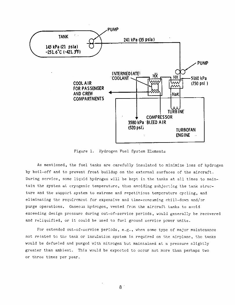
A conceptual diagram of the elements of an aircraft LH 2 fuel system is shown
in Figure i. Nominal pressures and temperatures are shown on the diagram for each
of the significant conditions which exist as the cryogenic fluid moves through the
system from tank to engine combustion chamber. Tank-mounted, submerged pumps boost
the pressure from the tank level to 221 kPa (35 psia) for delivery through the feed
system as a sub-cooled liquid to high pressure pumps mounted in each engine nacelle.
There the pressure is raised to approximately 5,160 kPa (750 psi) where, as a gas,
it passes through a heat exchanger and picks up heat from a secondary coolant,
e.g., a mixture of sodium and potassium (NaK), which has been used to cool the
engine high pressure turbine stages. At about this same point, another heat
exchanger, this one using a less exotic fluid as an intermediate coolant (e.g., a
water-glycol mix), can be employed to cool the air bled from the compressor to
pressurize the passenger and crew compartments, thus eliminating the need for con-
ventional mechanical refrigeration equipment for an environmental control system
(ECS). Accounting for the pressure drop through the heat exchangers, engine control
valves, and fuel injection system, the fuel reacts in the engine combustion chamber
at the design pressure of 3580 kPa (520 psi).
TANK ' "145kPa (21 psla)-25L 6°C (-421. 3°F)
COOLA IR
/PUMP
FORPASSENGERAND CREWCOMPARTMENTS
241 kPa (35 psla)
C C_ PUMPINTERMEDiATE1 H-)(
'COOLANT_ nA HX -----5160 kPa
,,,oos,,
I I TURBINE• _ COMPRESSOR
3580 kPa BLEED AIR
(520psi_ TURBOFAN
ENGINE -.
Figure i. Hydrogen Fuel System Elements
As mentioned, the fuel tanks are carefully insulated to minimize loss of hydrogen
by boil-off and to prevent frost buildup on the external surfaces of the aircraft.
During service, some liquid hydrogen will be kept in the tanks at all times to main-
tain the system at cryogenic temperature, thus avoiding subjecting the tank struc-
ture and the support system to extreme and repetitious temperature cycling, and
eliminating the requirement for expensive and time-consuming chill-down and/or
purge operations. Gaseous hydrogen, vented from the aircraft tanks to avoid
exceeding design pressure during out-of-service periods, would generally be recovered
and reliquified, or it could be used to fuel ground service power units.
For extended out-of-service periods, e.g., when some type of major maintenance
not related to the tank or insulation system is required on the airplane, the tanks
would be defueled and purged with nitrogen but maintained at a pressure slightly
greater than ambient. This would be expected to occur not more than perhaps two
or three times per year.
.
When the tanks themselves, or their insulation system, require inspection or
repair, after being defueled and purged with nitrogen the tanks would be vented
to the atmosphere to provide safe entry by maintenance personnel. During the
early service life of the aircraft, it is expected that the regulating agencies
might demand frequent tank and insulation inspections to assure continued flight
worthiness and to gain service knowledge. In routine commercial airline service,
after cryogenic tank integrity is well established, this kind of inspection would
be considered to be in the same category as that required for aircraft primary
structure, i.e., normally performed at intervals of 8,000 to i0,000 hour of opera-
tion, or roughly every two or two and one-half years.
Operational procedures for LH 2 fueled aircraft are conceived as being not
radically different from current practices. The equipment would be different, of
course, but the manpower and the elapsed time per function should be virtually the
same. For example, during a routine fueling process, estimated to require about
30 minutes for normal turn-around, cabin attendants can perform housekeeping chores,
cargo can be loaded, and food service stowed. Upon completion of these services,
the people can board and the flight would then be ready for takeoff. With properly
designed equipment and scheduling of operations there is no obvious reason a
hydrogen-fueled airplane should require more time for turn-around than conventional
Jet-fueled aircraft.
3.1.2 Tank and Insulation System
Design of tanks to contain liquid hydrogen efficiently in the subject aircraft
is recognized as one of the critical technical challenges. _o basic types of
tank designs were considered: integral, where the tank serves both as the container
of the fuel and also carries the fuselage structural loads; and non-integral, in
which case the tank merely contains the fuel and a separate structure is provided to
resist fuselage axial, bending, and shear loads.
Based on a previous analysis of the differences between integral and non-
integral cryogenic tanks (Ref. 5), it was decided that the integral type tanks
would be used wherever feasible in the present conceptual design study. It is
emphasized, however, that this was an arbitrary choice and is a subject which
deserves significant design and development attention. Design conditions for sub-
sonic aircraft are significantly different than those for supersonic aircraft (Ref. 5),
so it does not necessarily follow that the type of tank design preferred for one
application would necessarily be best for the other. In addition, there are manyother potentially attractive tank design concepts waich should also be evaluated.
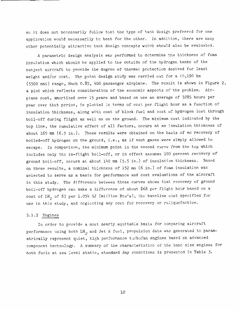
A parametric design analysis was performed to determine the thickness of foam
insulation which should be applied to the outside of the hydrogen tanks of the
subject aircraft to provide the degree of thermal protection desired for least
weight and/or cost. The point design study was carried out for a 10,190 km
(5500 nmi) range, Math 0.85, 400 passenger airplane. The result is shownin Figure 2,
a plot which reflects consideration of the economicaspects of the problem. Air-
plane cost, amortized over 15 years and based on use an average of 3285 hours per
year over that period, is plotted in terms of cost per flight hour as a function ofinsulation thickness, along with cost of block fuel and cost of hydrogen lost through
boil-off during flight as well as on the ground. The minimumcost indicated by the
top line, the cumulative effect of all factors, occurs at an insulation thickness ofabout 165 mm(6.5 in.). These results were obtained on the basis of no recovery of
boiled-off hydrogen on the ground, i.e._ as if vent gases were simply allowed to
escape. In comparison, the minimumpoint in the second curve from the top which
includes only the in-flight boil-off, or in effect assumesi00 percent recovery ofground boil-off, occurs at about 140 mm(5.5 in.) of insulation thickness. Based
on these results, a nominal thickness of 152 mm(6 in.) of foam insulation was
selected to serve as a basis for performance and cost evaluations of the aircraft
in this study. The difference between these curves shows that recovery of ground
boil-off hydrogen can makea difference of about $68 per flight hour based on a
cost of LH2 of $3 per 1.054 GJ (million Btu's), the baseline cost specified foruse in this study, and neglecting any cost for recovery or reiiquefaction.
3.1.3 Engines
In order to provide a most nearly equitable basis for comparing aircraft
performance using both LH 2 and Jet A fuel, propulsion data was generated to param-
etrically represent quiet, high performance turbofan engines based on advanced
component technology. A summary of the characteristics of the base size engines for
both fuels at sea level static, standard day conditions is presented in Table 3.
i0
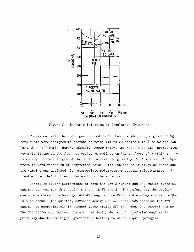
Figure 2.
4OO
04 6 8
L I ! t
50 100 150 200INSULATIONTHICKNESS
I0 IN.
!
250 mm
Economic Selection of Insulation Thickness
Consistent with the noise goal stated in the basic guidelines, engines using
both fuels were designed to operate at noise limits 20 decibels (dB) below the FAR
Part 36 specification during takeoff. Accordingly, the nacelle design incorporates
acoustic lining on the fan duct walls, as well as on the surfaces of a splitter ring
extending the full length of the duct. A variable geometry inlet was used to sup-
press forward radiation of compressor noise. The fan has no inlet guide vanes and
the turbine was designed with appropriate rotor/stator spacing relationships and
treatment so that turbine noise would not be a factor.
Installed cruise performance of both the Jet A-fueled and LH2-fueled turbofan
engines derived for this study is shown in Figure 3. For reference, the perfor-
mance of a current technology turbofan engine, the Pratt and W?.itney Aircraft JT9D,
is also shown. The quieted, advanced design Jet A-fueled 1985 state-of-the-art
engine has approximately 13 percent lower cruise SFC than does the current engine.
The SFC difference between the advanced design Jet A and LH2-fueled engines is
primarily due to the higher gravimetric heating value of liquid hydrogen.
ii
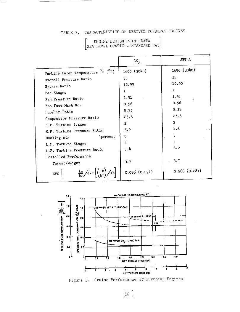
TABLE3. CHARACTERISTICSOF DERIVEDTURBOFANENGI_[ES
ENGINEDESIGNPOINTDATA ]SEALEVELSTATIC- STANDARDDAY
Turbine Inlet TemperatureOK(OR)Overall PressureRatio
BypassRatioFanStagesFanPressureRatioFanFaceMachNo.Hub/TipRatioCompressorPressureRatioH.P. Turbine StagesH.P. Turbine PressureRatioCooling Air ipercent
LH2
1690 (3040)
35
12.95
1
I.51
0.56
0.35
23.3
2
3.9
0
JET A
1690 (3040)
35
L.P. Turbine Stages
L.P. Turbine Pressure Ratio
Installed Performance
Thrust/Weight
SFC I
h
T._+
3.7
0.096 (O.09h)
10.90
1
1.51
0.56
0.35
23.3
2
h.6
5
h
6.2
3.?
0.286 (0.281)
1,21.2
1.0
tit
_ 0.8 OJ
i 0.11 0.6
0.4 0.4
u.
u 0.2 0.2m
0
!
0
Figure 3.
MACH O.M. TO,670m (3S.O00 leT.)
"-------_ OEIIIVEO JET A TURBOFAN
k.
-,-....
_ ...REFERENCE: .rrgo_
t
0ERIVED LH 2 TURBOFAN
|
0.I 1+0 1.s 2+0 2+S 3.o 3.t; +I.0
NET THRUST ll000 d_Nl
J+ J + , , I. , I I _ l I
1 2 3 4 S + ? II I
NET THRUST (1000 LB)
Cruise Performance of Turbofan Engines
I10
12
3.2 PASSENGER AIRCRAFT
This program to investigate the potential of using liquid hydrogen as fuel
for commercial transport aircraft was viewed as an opportunity to explore many dif-
ferent design configurations to see which offered maximum advantage for efficient
containment of the low density, very energetic, cryogenic liquid. Compared with
conventional hydrocarbon (Jet A) aircraft fuel on an energy per unit weight basis,
LH 2 is higher by a factor of 2.8; however, on the basis of energy per unit volume,
LH 2 is lower by a factor of 3.78. In other words it takes 3.78 times more volume
to contain the weight of LH 2 to produce a given impulse, compared with the volume
required for the 2.8 times more weight of Jet A which will produce the same impulse.
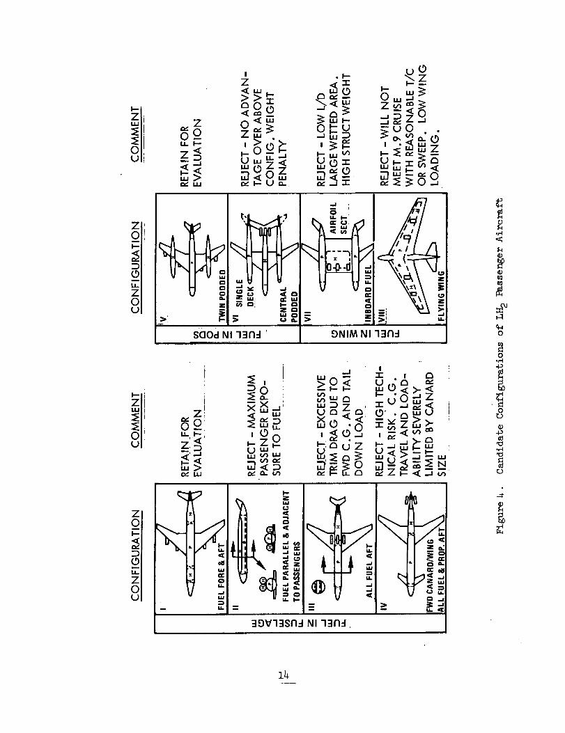
3.2.1 Configuration Concepts
With this in mind, plus consideration of the desirability of achieving maximum
separation of passengers from the fuel for safety reasons, a broad range of airplane
configuration concepts was explored. The design possibilities were categorized as
follows:
• Fuel in fuselage
• Fuel in pods
• Fuel in wing
Representative examples of designs in each of these categories are illustrated
in Figure 4, along with brief comments concerning reasons for their acceptance or
rejection. The result of these considerations was a conclusion that the character-
istics of LH2 were not so peculiar that conventional aerodynamics and structural
design practices could be violated with impunity.
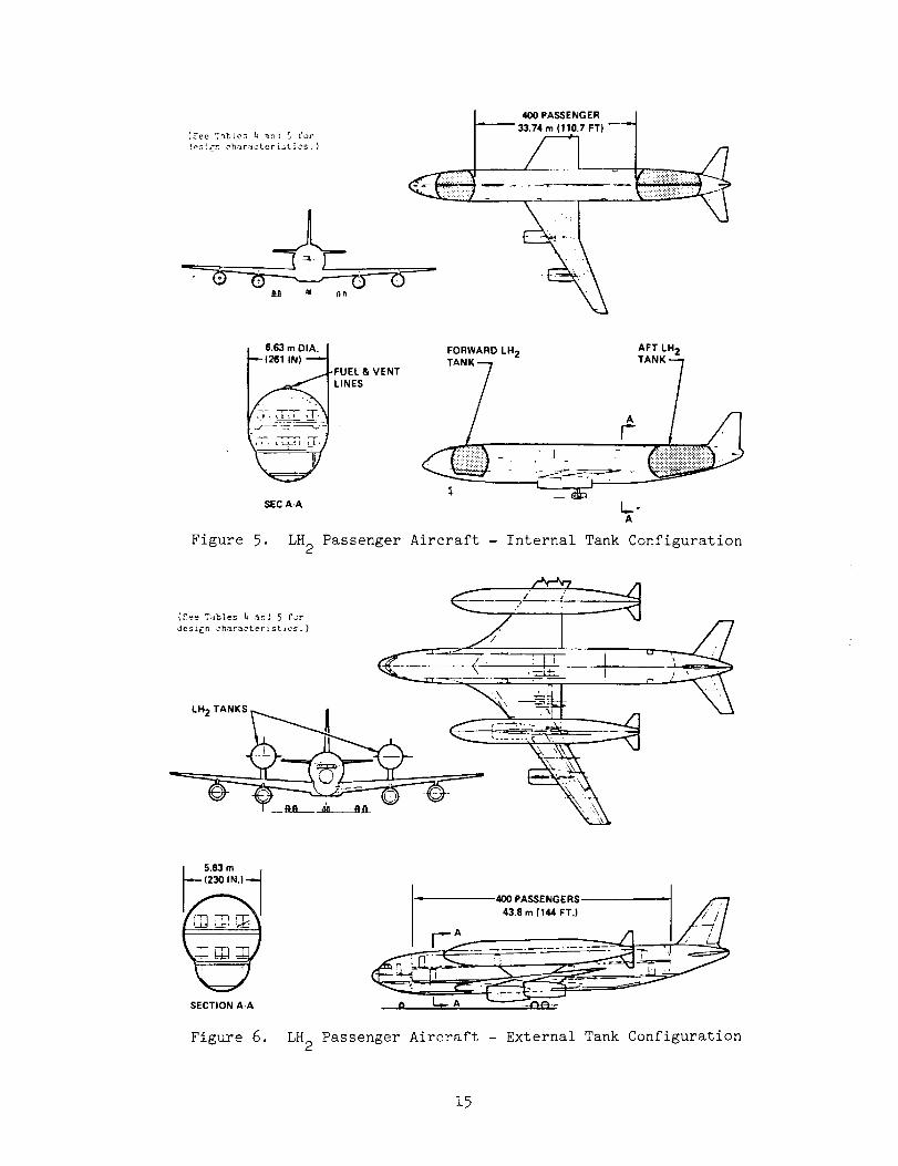
The two airplane design concepts selected for detail consideration are illus-
trated in Figures 5 and 6. Externally, there is little to distinguish the con-
figuration of the internal tank arrangement shown in Figure 5 from current,
conventionally-fueled, wide-body transports. Internally, the arrangement is unique.
The passengers are located in the central portion of the fuselage in a double-deck
arrangement with the fuel tanks located forward and aft. The fuel tanks occupy
the full usable cross-section of the fuselage. As a result, there is no provision
for physical access between the passenger compartment and the flight station. The
13
l
z!0 0'IJ,,, I-',,'
Z. D
o_ ILl
I
" _ .
uj.-IUd U r_
_zO , _ o.__ ,_.<_
,.,,,, b,", u z b.,1_ _ _...,,,._ _,_o__ _-_
1
i 10 L
0 .1,1
o
o
o,40
0
P_q4
0t.D
o4_
0
{gee Tables I, _n! 5 for
l_zlgn chara,_'terist_cs. )
400 PASSENGER _i
6.63 m DIA. I
_(261 INI --'1_._FUEL & VENT
SEC A-A
Figure 5.
FORWARD LH 2 AFT LH 2
__] /'_ TANK 1
A
LH 2 Passenger Aircraft - Internal Tank Configuration
/ Ioh_r_terist ios, )
LH 2 TANKS r_ i
] 5.83 m
(230 IN.)
SECTION A-A
Figure 6.
400 PASSENGERS _ /;---,-/
43,S m (144 FT.) J _lr/
r A //...... ---.........-- -_ "I
I r_'-Z -_ ';
LH 2 Passenger Aircraft - External Tank Configuration
15
passengers are seated in a 2-4-2 arrangement on both decks for a total of 16 seats
per row. Cargo is carried in space provided below the passenger compartment. Total
payload weight for the 400 passenger design is 88,000 pounds.
The external tank configuration illustrated in Figure 6 carries the passengers
in a comparable arrangement except that the fuselage diameter is somewhat smaller
so the passengers are seated in a 2-2-2 arrangement for a total of 12 per seat row.
This preserves the fineness ratio (length to diameter ratio) of the fuselage for
aerodynamic advantage. All of the liquid hydrogen fuel is carried in the external
tanks mounted on pylons above the wing. This configuration was originally proposed
to provide an evaluation of potential advantages thought to exist for that configu-
ration in safety, operations, and maintenance. It was recognized that there would
be a performance penalty associated with carrying large, externally-mounted tanks,
but it was felt that the accessibility of the tanks for inspection and repair, plus
the safety associated with minimum hazard from effects of leaks, in addition to
achieving maximum separation of passengers from fuel, might offer compensating
advantages. Analysis did not confirm that these potential advantages were sub-
stantial enough to outweight the performance superiority of the more conventional
internal tank configuration.
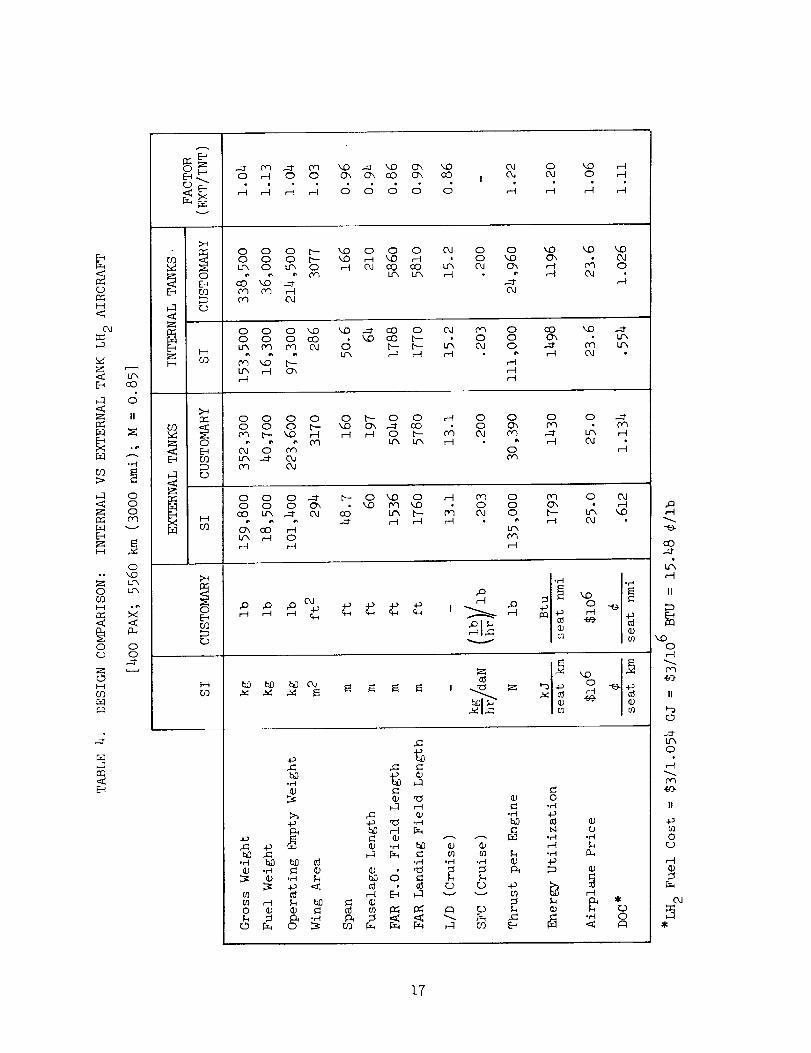
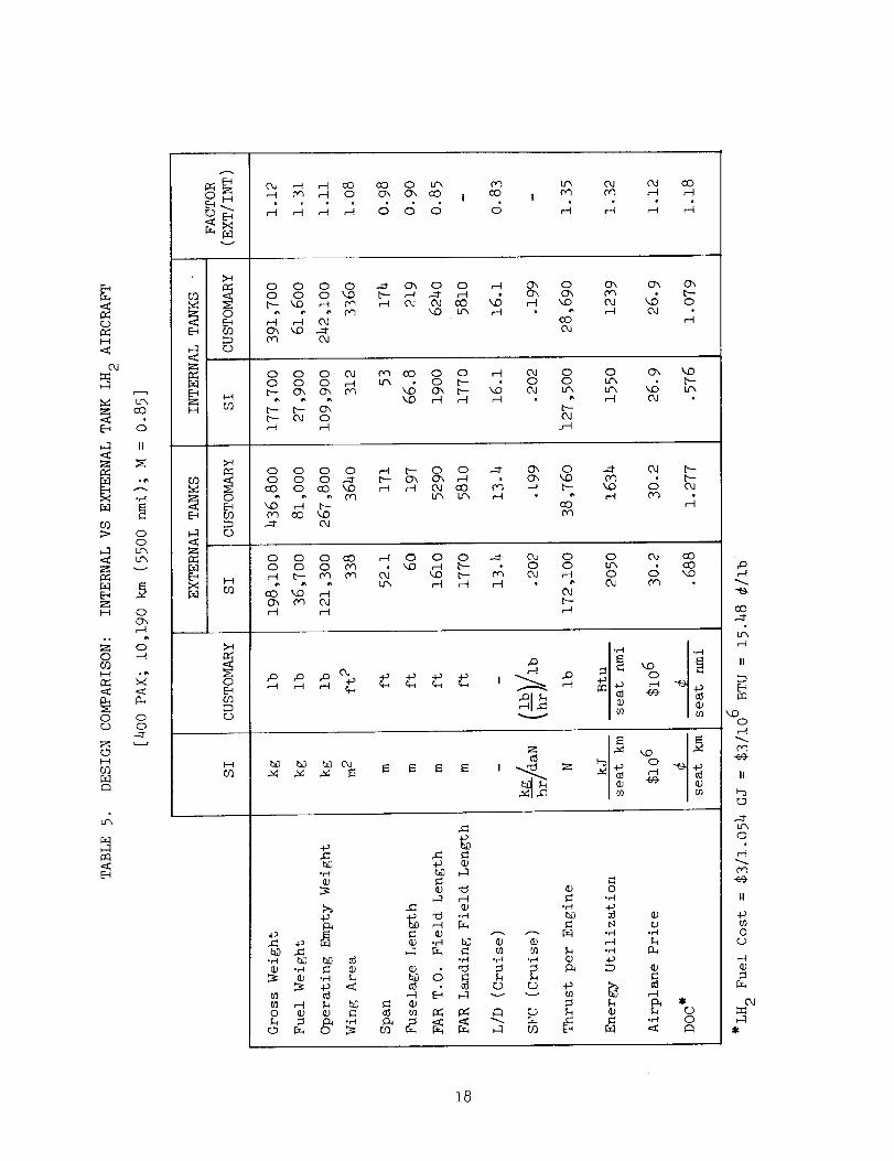
A comparison of several key design and performance parameters for these two
design concepts of LH2-fueled aircraft is presented in Tables 4 and 5 for the
5560 km (3000 nmi) range aircraft, and the 10,190 km (5500 nmi) range aircraft,
respectively. In only three of the fifteen parameters listed is the internal tank
design found to have a rating not as favorable as the external tank configuration.
However, the last three items in the tables are the most significant. In each of
these, energy utilization, airplane price, and direct operating cost, the internal
tank configuration is the obvious choice by a large margin.
The candidate internal and external tank LH 2 aircraft designs were compared
and evaluated on the basis of operation, maintenance, and safety considerations,
in addition to the performance characteristics. From an operations point of view,
it was concluded the internal tank design was preferred. Considering maintenance
aspects, the external tank configuration could be seen to offer definite advantages.
In safety, there was little basis for a clear cut decision in selecting a preferred
design configuration except that the magnitude of the task of providing the required
protection against engine burst for the external tank configuration made the internal
tank approach more feasible and therefore more attractive.
16
C_
Z H
O,_ O
z oF-_ v
H
O
Lf_
O_
O OrJ O
03
E-_
E_
F_
O_
°E_0_
CO
o0_
P_
0_
E_C_
C)
H
0 _ 0 0 C_ a_ cO O'x cO
j _ _ j c_ c_ c_ c_ c_04 O..I O
O O O _- _ O O O O_1 O OO O O _'_ _ _ _D H -- OLrx O _X O _ 04 CO CO _'_ 04 C_
Oq Oq _ C_l
Ox OJ_ O
,--I C_
O O O _ _ .-_ CO O O_ _ O0 0 0 CO _0 oO _ 0 0
_ r--I 0"_ r'-t_ r"t
CO kD ..-=tOX U'_
e"t _
O O O O O _ O OO O O _ _D C_ _ CO
_ o m
r-_ o o
¢_1 c,n
o
o o .._f¢3 ¢¢_
,-t
O O O _ _ O _D O .--I Dq OO O O C_ _O _ _O O O
CO Lf_ ._" O4 C_ U"x b-- _ 04 O
O'_ CO _ Lrx
O OJ
t_- _ _OO_
v
°.-I °_
O
b_ bD 04
-p
O _ •
_ O
0.el
0r'-I °,"t
.,_
_) I-t r..)
_ .el 0._ ¢::1
,.-.-t
cO
e'-t
II
M_0,--t
f_3
II
0
It
.._
0
r-"l
0.1
i7
o
H
oJ
Z
"H
co_- o
o_-l um•_ um
v
E_
H oo_
o0")
o o
O
f_
c0
O
c.)
H
_ 4 H _ 8 _ 8 8 4
oJ oJ co0"l H _-I
o o o o .--1- o_ o o ,-t o_ oo o o _D b.- ,-1 .--1- _t O_ O-,b- LID ,-4 Dq _--_ OJ OJ oO _ ,--I _D
c_ oJ
o_ o_ o_
H OJ °
o o o 0J c,_ oo o o ,-t 0J oo o o r-t _ O b- o o
b- b-- O'x ["--b- OJ O O.I
O O'_ LDum b-um '_ um,-1 o.I
o o o o ,-4 b- o o .-_ c_ oo o o -._ b- o_ Ox ,-I -- o_ ko
co o co LO H ,--I Od oO 0'_ _-H b-
,--I b- COc_ oO LD
-.1 O.1
•-.1" OJ b-c_ b-
O O O CO ,--1 O O O .-_ OJ OO O O Dq _ _1 b-- O OH b- 0q _ O_ b-',D c,_ OJ ,--t
cO _ ,--t OJO'x _ OI b--
O OJ 00um aDo (_ ,.o
, o,_, i_ 0_
b_ _ b0 0J , = o
°H
bD ,_
O ¢; • I_
,c
_._ _
_0
•_I ,,-I .H
b0 O _ _
o
•H ,.-I
.H
•_ 0
#a
co
LF_
II
_Do,-I
II
c_
Lr_o
II
o__)
_-_
oJ
18
The following is a summary of the conclusions reached regarding the two design
concepts in each of the more significant areas of consideration:
Characteristics Preferred Tank Arrangement
Operations Internal
Maintenance External
Safety Internal
Weight Internal
Size External
Energy utilization Internal
Price Internal
Direct Operating Cost Internal
Accordingly, the internal tank design concept for LH2-fueled passenger aircraft
was selected for further analysis and subsequent comparison with reference Jet A
aircraft.
3.2.2 Benefits Evaluation
A parametric design study was conducted to provide reference (Jet A-fueled)
aircraft for direct comparison with the subject LH2-fueled aircraft. Particular
care was taken to assure that the competitive aircraft were designed to carry the
same payload, the same distance, at the same cruise speed, and to operate with the
same set of design constraints and requirements as their counterparts.
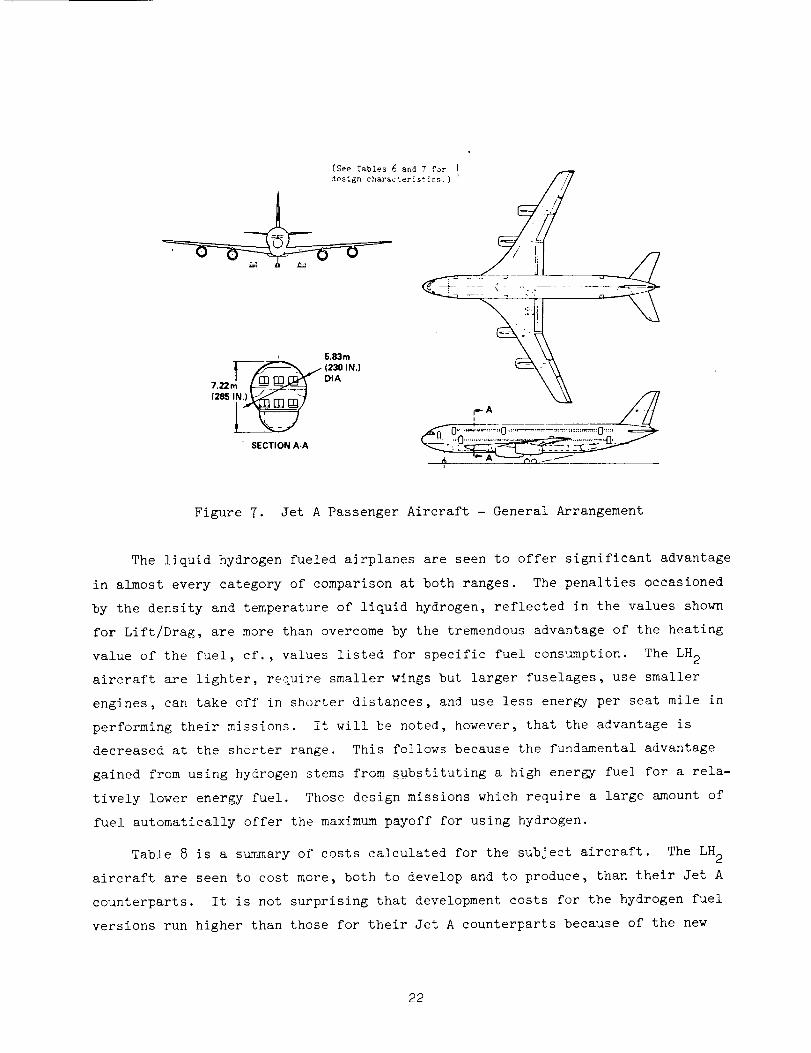
The general arrangement of the Jet A aircraft is shown in Figure 7. The
fuselage arrangement is the same as that used for the external tank hydrogen
vehicle. All fuel is contained in the wing box structure resulting in some struc-
tural load relief for this wing compared to the hydrogen version.
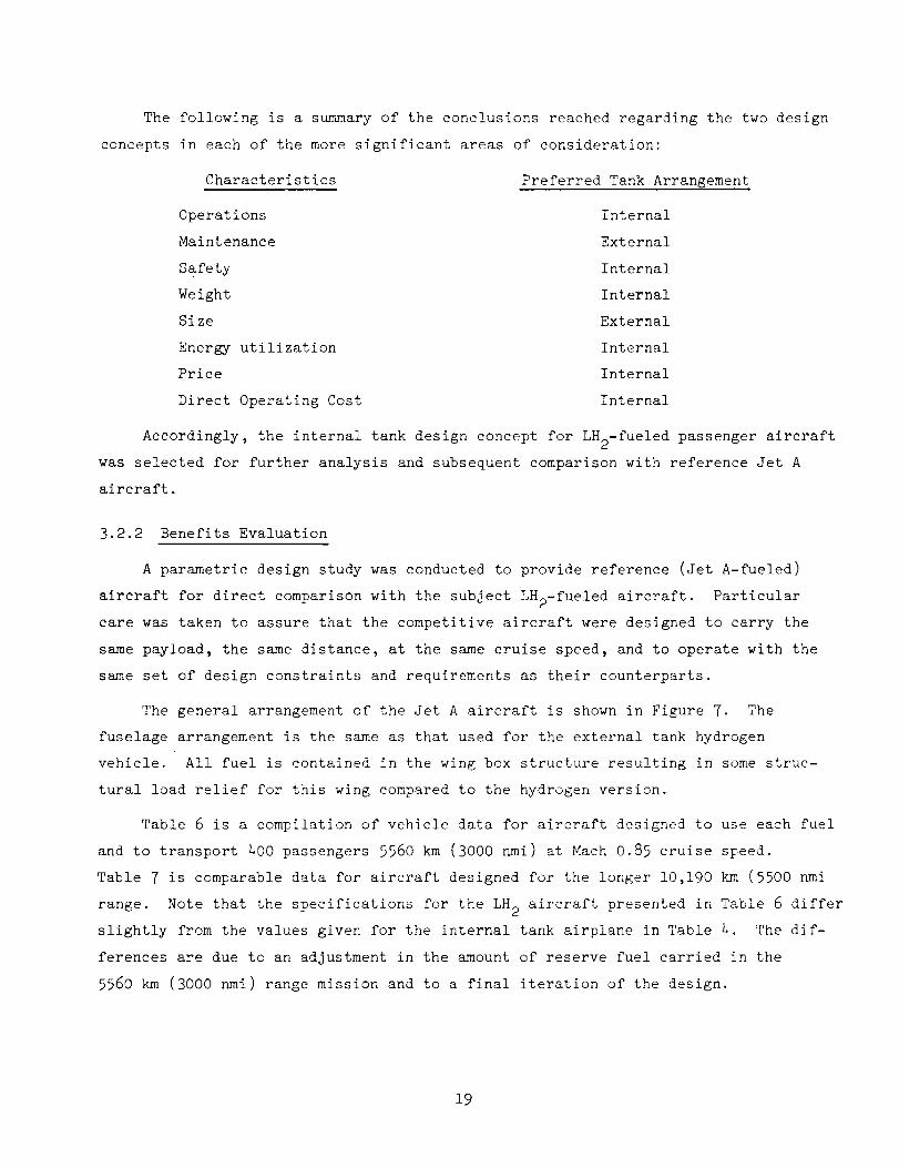
Table 6 is a compilation of vehicle data for aircraft designed to use each fuel
and to transport 400 passengers 5560 km (3000 nmi) at Mach 0.85 cruise speed.
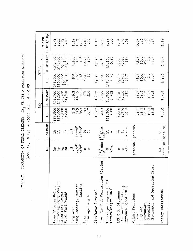
Table 7 is comparable data for aircraft designed for the longer 10,190 km (5500 nmi
range. Note that the specifications for the LH 2 aircraft presented in Table 6 differ
slightly from the values given for the internal tank airplane in Table h. The dif-
ferences are due to an adjustment in the amount of reserve fuel carried in the
5560 km (3000 nmi) range mission and to a final iteration of the design.
19
0c
H
O
F_CO
0_ umcO
< S
b>
0,I ,---
ooo
F-'I v
C_
o<_ _o
um
o ._O_
o oco oH
Co;
or_
,A
c_
v
o
I---t
oE_cO
OE_ca
U
co
,-I o_ u"_ ooC_l cho_o
_ _ _ _ _ _ _ _ •o_oo_ _ _ o_ _
__' _ 4 _ _'
o ooooooo
o _o.._ od ,--t
_o_ _ _ o_ oo__0._ _ _ _ __o_ _ _ _ _
m _ _ 6 _8 w_
oooJ
oo
ooooooi.r_ .__ o0
ox o"1 ._
r-f O_0 (_ O _ID OJ O .--I b-- O O_O _--IO0 U'xLD ',,D Cm O Lrx C_LD_D0"_'_0,-d" -- u-x L/_ • .--d"L'--
LO
r-]
C,,IO0 00 b-e0
LO _ b--',,Db-C_ CLIC'J .--t
OOC_
0qeq
ooooooc_o0q
oJ a0 ,_
0J
O_O_
ooooooooo um b-_D
u", _ r---I r-I
0"_ b--co I._-_ LD c_ O O O O 1-_cO D'_cO .LID oO O O O'x O_b--oJ u'_,--,-,d-o LmJ L---b- c_
_ 0 r--I r---t,---tr--t
O_ _O_
0._ _p -p .p "I_
-.o
o
o
4._
c!,,--I
0_O
0•H _I
o _D 0 -_
p _ rq ;:s _._
o
o',4:)0,1
,-t
ocoLf_
O
O,H
r-t
O.H_p
.H,'-I
I-t
20
oJ
f_
v
_ H_O_o _
igll
.._- b- LrX OJ O OJ OJ __- Lr_ 0:3 0 O.1OJ O O r--I O_ r-t C_ r-_oO OJ O_ O_
__ ' _ 0_ _ _4 "
_ u'm Lrx OJ_OJ b-cO LrX h-
i • • 0 •,-t
(_ oooooooo0J.-1- Lrxoo
umOJ r-_ r-I
_D U'_ ,--I b- ,--I r--I O U_ O O.-_"CO OJ O • C_ O_ CO O 0d O'x_--I O_,--I i--I r--I .-._ ,--I I._ O_ OJ _-t
,--I _1 O OJ I_- I.,'X
_O_,will
-.-t00
Zf-i.1corT_
oooooooocM aO o I._
b-- O umLO0o ,-_ b- oOOJ ,--I
O_ OOO OJ O ,-t O O LI_ I.FXO b-
f,_ ',,D u'x O-, _
L_
< c;
,el
_ OOOOOOOOb--- r-t OxkD
O *'
__ _ _ o_ oo__.o_ o _ O_ _
_ o _
o_
oJ
,-4oo
i..f%v
O
oooooooo
_o_
¢w_ O_IY_ (Y_ b- b- _ ooo o o 1._,_LO o_ Lr_ O O OoO O _'-- •
,--t b-- ,--I ,--t
H
_O_
o
cof-_
oc_
,-_ ,-I
oH ,--t
_._ XO "_
O O0'_ O
or..)
pcl
r_
r_
H
o
©o
©
+_.,--i
bD _;
4._ .H .,--I
I-t ,-q ,-t
_+_ .H _ __+_
__ _ 0+-_
.eq
v
o
.. ---_ .H m m _ o
•,--I .H P_ :_ ._
D'J
i.-i
+_
O
o
o o _ _
0)N
.H
¢)
i1)
0,r"t
.,-'1
'H
<D
21
(See Tables 6 and 7 for i
design character is '_ Z-7
_ _ /I
, 5._m
c 3O,N.,
Figure 7. Jet A Passenger Aircraft - General Arrangement
The liquid hydrogen fueled airplanes are seen to offer significant advantage
in almost every category of comparison at both ranges. The penalties occasioned
by the density and temperature of liquid hydrogen, reflected in the values shown
for Lift/Drag, are more than overcome by the tremendous advantage of the heating
value of the fuel, cf., values listed for specific fuel consumption. The LH 2
aircraft are lighter, require smaller wings but larger fuselages, use smaller
engines, can take off in shorter distances, and use less energy per seat mile in
performing their missions. It will be noted, however, that the advantage is
decreased at the shorter range. This follows because the fundamental advantage
gained from using hydrogen stems from substituting a high energy fuel for a rela-
tively lower energy fuel. Those design missions which require a large amount of
fuel automatically offer the maximum payoff for using hydrogen.
Table 8 is a summary of costs calculated for the subject aircraft. The LH 2
aircraft are seen to cost more, both to develop and to produce, than their Jet A
counterparts. It is not surprising that development costs for the hydrogen fuel
versions run higher than those for their Jet A counterparts because of the new
22
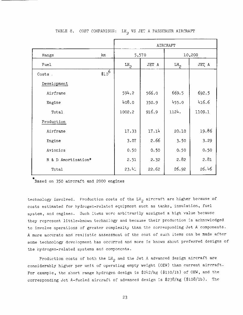
TABLE8. COSTC0_ARISON: LH2 VS JET A PASSENGERAIRCRAFT
AIRCRAFT
Range km 5,570 10,200
Fuel LH2 JET A LH2 JET A
$z06Costs
Development
Airframe
Engine
Total
Production
Airframe
Engine
Avionics
R & D Amortization*
Total
594.2
408.0
1002.2
17.33
3.07
O.5O
2.51
23.h1
566.0
350.9
916.9
17.14
2.66
0.50
2.32
22.62
669.5
455.0
1124.
20.10
3.50
0.50
2.82
26.92
692.5
416.6
1109.1
19.86
3.29
0.50
2.81
26.46
Based on 350 aircraft and 2000 engines
technology involved. Production costs of the LH 2 aircraft are higher because of
costs estimated for hydrogen-related equipment such as tanks, insulation, fuel
system, and engines. Such items were arbitrarily assigned a high value because
they represent little-known technology and because their production is acknowledged
to involve operations of greater complexity than the corresponding Jet A components.
A more accurate and realistic assessment of the cost of such items can be made after
some technology development has occurred and more is known about preferred designs of
the hydrogen-related systems and components.
Production costs of both the LH 2 and the Jet A advanced design aircraft are
considerably higher per unit of operating empty weight (0EW) than current aircraft.
For example, the short range hydrogen design is $242/kg ($110/Ib) of OEW, and the
corresponding Jet A-fueled aircraft of advanced design is $238/kg ($i08/ib). The
23
sales price of current widebody transport aircraft, e.g., L-1011 and DC-!O, is
approximately $183/kg ($83/ib) of OEW.
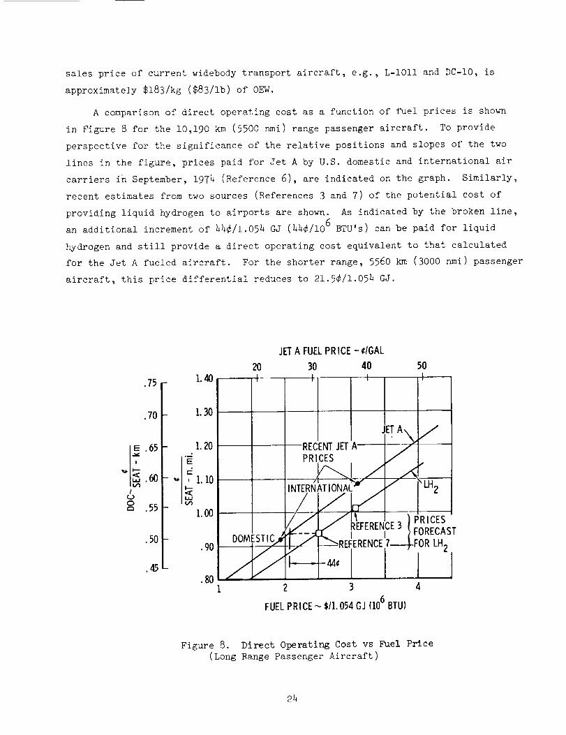
A comparison of direct operating cost as a function of fuel prices is shown
in Figure 8 for the 10,190 km (5500 nmi) range passenger aircraft. To provide
perspective for the significance of the relative positions and slopes of the two
lines in the figure, prices paid for Jet A by U.S. domestic and international air
carriers in September, 1974 (Reference 6), are indicated on the graph. Similarly,
recent estimates from two sources (References 3 and 7) of the potential cost of
providing liquid hydrogen to airports are shown. As indicated by the broken line,
an additional increment of 44¢/1.054 GJ (44¢/106 BTU's) can be paid for liquid
hydrogen and still provide a direct operating cost equivalent to that calculated
for the Jet A fueled aircraft. For the shorter range, 5560 km (3000 nmi) passenger
aircraft, this price differential reduces to 21.5¢/1.054 GJ.
.75
JET A FUELPR ICE - ¢/GAL
2O 30 40 501.40 , , , ,
,70
[_ .656O
"_ .55
.50
.45
1.30
I.20
-'_ , 1.10
1.00
pRRECENTcEsJETA J/__ET"A_"//
,_RN/_A_s "/'_
IN / "LH2
FORECAS
•90 / , L---_-REFERENCE7----_.FORLH2
- .8o /44¢
I 2 3 4
FUEL PRICE --,$11.054GJ (106BTU)
Figure 8. Direct Operating Cost vs Fuel Price
(Long Range Passenger Aircraft)
24
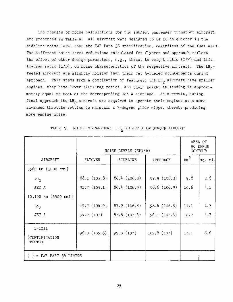
The results of noise calculations for the subject passenger transport aircraft
are presented in Table 9. All aircraft were designed to be 20 db quieter in the
sideline noise level than the FAR Part 36 specification, regardless of the fuel used.
The different noise level reductions calculated for flyover and approach reflect
the effect of other design parameters, e.g., thrust-to-weight ratio (T/W) and lift-
to-drag ratio (L/D), on noise characteristics of the respective aircraft. The LH 2-
fueled airhraft are slightly noisier than their Jet A-fueled counterparts during
approach. This stems from a combination of features; the LH 2 aircraft have smaller
engines, they have lower lift/drag ratios, and their weight at landing is approxi-
mately equal to that of the corresponding Jet A airplane. As a result, during
final approach the LH 2 aircraft are required to operate their engines at a more
advanced throttle setting to maintain a 3-degree glide slope, thereby producing
more engine noise.
TABLE 9. NOISE COMPARISON: LH 2 VS JET A PASSENGER AIRCRAFT
AIRCRAFT
5560 km (3000 nmi)
LH 2
JET A
10,190 km (55OO nmi)
LH 2
JET A
L-1011
(CERTIFICATION
TESTS)
FLYOVER
88.1 (i03.8)
92.7 (105.1)
96.0 (105.6)
( ) = FAR PART 36 LIMITS
NOISE LEVELS (EPNdB)
SIDELINE
86.4 (106.3)
86.h (106.9)
87.2 (106.8)
87.8 (107.6)
95.0 (107)
APPROACH
97.9 (106.3)
96.6 (106.9)
98.2 (106.8)
96.7 (107.6)
102.8 (107)
AREA OF
90 EPNdB
CONTOUR
km 2 sq. mi
9.8 3.8
10.6 h.l
Ii.i 4.3
12.2 4.7
17.1 6.6
25
The areas at the airport which would be subjected to noise levels greater than
90 EPNdB are also listed. The LH 2 aircraft at both design ranges show smaller
areas thus affected. For comparative reference, noise levels for the Lockheed L-1011
wide-bodied aircraft measured during FAA certification tests are listed.
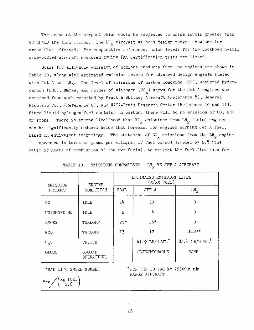
Goals for allowable emission of noxious products from the engines are shown in
Table I0, along with estimated emission levels for advanced design engines fueled
with Jet A and LH 2. The level of emissions of carbon monoxide (CO), unburned hydro-
carbon (UHC), smoke, and oxides of nitrogen (N0x) shown for the Jet A engines was
obtained from work reported by Pratt & Whitney Aircraft (Reference 8), General
Electric Co., (Reference 9), and NASA-Lewis Research Center (Reference i0 and ll).
Since liquid hydrogen fuel contains no carbon, there will be no emission of CO, UHC
or smoke. There is strong likelihood that NO emissions from LH 2 fueled enginesX
can be significantly reduced below that forecast for engines burning Jet A fuel,
based on equivalent technology. The statement of NO emissions from the LH 2 engineX
is expressed in terms of grams per kilogram of fuel burned divided by 2.8 (the
ratio of heats of combustion of the two fuels), to reflect the fuel flow rate for
TABLE i0. EMISSIONS COMPARISON: LH 2 VS JET A AIRCRAFT
EMISSION
PRODUCT
CO
UNBURNED HC
SMOKE
NO X
H20
ODORS
ENGINE
CONDITION
IDLE
IDLE
TAKEOFF
TAKEOFF
CRUISE
GROUND
OPERATIONS
GOAL
14
2
25*
13
ESTIMATED EMISSION LEVEL
(g/kg FUEL)
JET A
3O
4
15"
12
41.9 LB/N.MI. t
OBJECTIONABLE
LH 2
0
0
0
_12"*
82.h LB/N.MI.t
NONE
*SAE 1179 SMOKE NUMBER tFOR THE i0,190 km (5500n n_
RANGE AIRCRAFT
approximately equal thrust levels from both engines. Water vapor from the hydrogen
fueled airplane is nearly twice the amount produced by the Jet A design_ however,
it is still only a trace amountcomparedto moisture normally present in the
atmosphere.
Finally, considering the comparative safety of LH2 and Jet A fuels in aircraft,
the overriding conclusion is that the hazards associated with the use of LH2 canbe less than those with Jet A. For example, in an otherwise survivable crash in
which equal energy quantities of Jet A and hydrogen fuel are burned, the hydrogen
fire would result in significantly less damageto the surroundings, hence the
passengers, because of its relatively rapid burning rate and its extremely lowemissivity (radiant heat transfer).
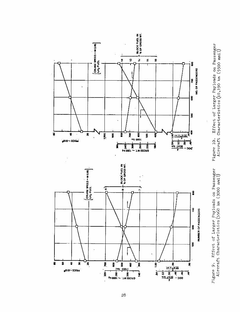
3.2.3 Effect of Larger Payloads
The effect of larger payload requirements on LH 2 aircraft design and operational
characteristics was investigated by establishing designs to carry 600 and 800 pas-
sengers over the specified ranges at Mach 0.85 cruise speed. All aircraft were
designed to the same guidelines used throughout the study for the 400 passenger
vehicles.
The same general arrangement of aircraft was retained in that passengers are
carried in a double-deck arrangement with fuel tanks both forward and aft. In order
to enlarge the passenger compartment to carry the required complement, yet not
exceed a realistic fuselage length, the fuselage diameter as well as its length
was increased. Thus, these larger aircraft retained about the same fuselage
fineness ratio as the 400 passenger design and permitted appropriate rotation
angles.
Trends of some of the significant parameters which are functions of aircraft
size are plotted in Figures 9 and i0 for the 5560 km range and the 10,190 km range
aircraft, respectively. Aircraft gross weight, block fuel fraction, production
price, and direct operating cost are all plotted to show their variation with pas-
senger capacity ranging from 400 to 800. The increasing flight efficiency of larger
aircraft is apparent in the decrease of the percentage of block fuel consumed, and
also in the lower direct operating cost as aircraft size increases.
27
:8
, :E
8
\
J
$
w_
_* ed,i-,i.
IIOL$_,331Hd
1
(sql O00t,), -- . ¥ _ i
6_ooot-- "j._ssouo
I
f
,,i|,,,,
e D •
_, ° t • •
l
Z
a.
|
@
_ °r'-C
t:_ oo
o u",.
o
_1 ,_
_3
0 %@
r..)
o _
%
% %
*e,._
o
o _v
o
@ o
(1.;o ..P
o
o
.r_
•(D',.
o
28
3.3 CARGO AIRCRAFT
For convenience, cargo aircraft designed to carry a 56,700 kg (125,000 Ib) load
a distance of 5560 km (3000 nmi) are called "small." Aircraft designed for the
113,400 kg (250,000 ib), 10,190 km (5500 nmi) range mission are called "large."
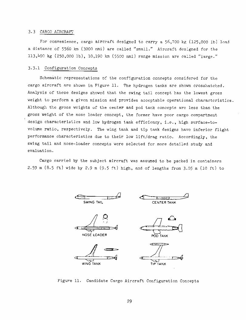
3.3.1 Configuration Concepts
Sehem&tic representations of the configuration concepts considered for the
cargo aircraft are shown in Figure ii. The hydrogen tanks are shown crosshatched.
Analysis of these designs showed that the swing tail concept has the lowest gross
weight to perform a given mission and provides acceptable operational characteristics.
Although the gross weights of the center and pod tank concepts are less than the
gross weight of the nose loader concept, the former have poor cargo compartment
design characteristics and low hydrogen tank efficiency, i.e., high surface-to-
volume ratio, respectively. The wing tank and tip tank designs have inferior flight
performance characteristics due to their low lift/drag ratio. Accordingly, the
swing tail and nose-loader concepts were selected for more detailed study and
evaluation.
Cargo carried by the subject aircraft was assumed to be packed in containers
2.59 m (8.5 ft) wide by 2.9 m (9.5 ft) high, and of lengths from 3.05 m (i0 ft) to
SWING TAIL CENTER TANK
/'t
NOSE LOADER l_OO TANK
WINGTANK T,PTANK
Figure Ii. Candidate Cargo Aircraft Configuration Concepts
29
12.2 m (40 ft). All study aircraft were configured to carry these containers in a
double-row arrangement. For the "small" aircraft, the double-row cargo compartment
is 22.6 m (74 ft) long and capable of containing one 3.05 m, one 6.1 m, and one
12.2 m container in each row. For the "large" aircraft, the cargo hold is 43.9 m
(144 ft) long and will contain three 12.2 m long containers and one 6.1 m, in each
row.
3.3.2 Analysis of LH? Aircraft Designs
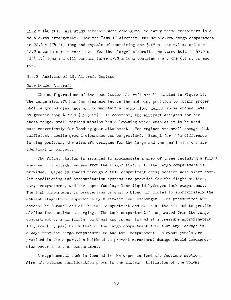
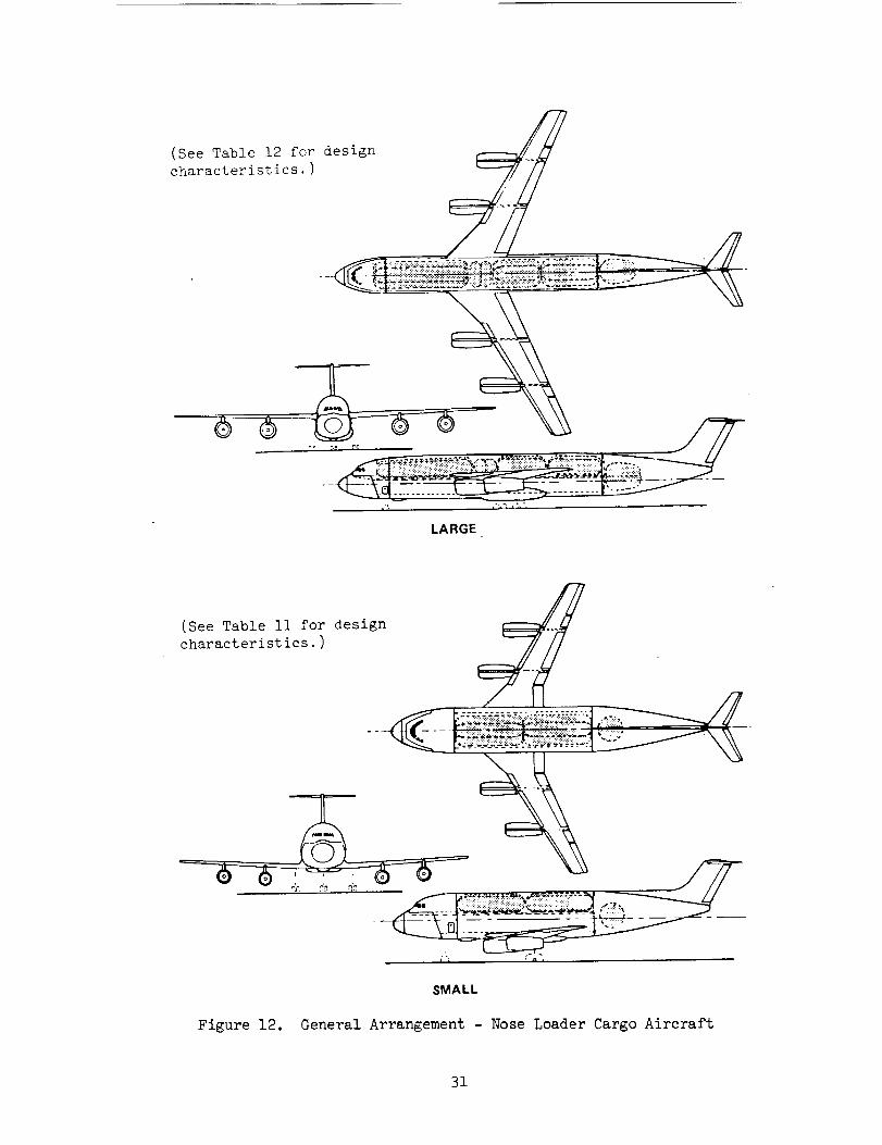
Nose Loader Aircraft
The configurations of the nose loader aircraft are llustrated in Figure 12.
The large aircraft has the wing mounted in the mid-wing position to obtain proper
nacelle ground clearance and to maintain a cargo floor height above ground level
no greater than 4.72 m (15.5 ft). In contrast, the aircraft designed for the
short range, small payload mission has a low-wing which enables it to be used
more conveniently for landing gear attachment. The engines are small enough that
sufficient nacelle ground clearance can be provided. Except for this difference
in wing position, the aircraft designed for the large and the small missions are
identical in concept.
The flight station is arranged to accommodate a crew of three including a flight
engineer. In-flight access from the flight station to the cargo compartment is
provided. Cargo is loaded through a full compartment cross section nose visor door.
Air conditioning and pressurization systems are provided for the flight station,
cargo compartment, and the upper fuselage lobe liquid hydrogen tank compartment.
The tank compartment is pressurized by engine bleed air cooled to approximately the
ambient stagnation temperature by a ram-air heat exchanger. The pressurized air
enters the forward end of the tank compartment and exits at the aft end to provide
airflow for continuous purging. The tank compartment is separated from the cargo
compartment by a horizontal bulkhead and is maintained at a pressure approximately
10.3 kPa (1.5 psi) below that of the cargo compartment such that any leakage is
always from the cargo compartment to the tank compartment. Blowout panels are
provided in the separation bulkhead to prevent structural damage should decompres-
sion occur in either compartment.
A supplemental tank is located in the unpressurized aft fuselage section.
Aircraft balance consideration prevents the maximum utilization of the volume
3O
(See Table 12 for design
characteristics.)
LARGE
(See Table ii for design _,..;_
characteristics. ) J/•___._;:_-_ :,_,_-:'-_-:s:--1 ._
SMALL
Figure 12. General Arrangement - Nose Loader Cargo Aircraft
31
available in the aft fuselage. To maintain acceptable c.g. travel fuel from this
supplemental tank is used first during a flight.
A three-lobe cross-section tank design was selected over other candidate shapes
for the main tanks of the subject aircraft on the basis of overall vehicle per-
formance advantages. It should be noted that this selected tank design, in contrast
to that previously discussed for the passenger aircraft, uses the non-integral
structural concept. In the nose loader cargo aircraft the integral design did not
lend itself to full advantage because of the irregular shape of the volume along
the spine of the aircraft above the cargo compartment. This difference between
tank design concepts selected for the passenger and the cargo aircraft involved
in this study illustrates that no one concept will necessarily be best for all
applications. There are a large number of tank design and insulation concepts which
should be investigated and evaluated before final choices are made for development
of hardware for any particular application. In the subject study the effort was
limited to simply selecting good representative tank designs to permit focusing on
the broader objective of evaluation of the potential of LH 2 as a fuel for transport
aircraft.
Swing Tail Aircraft
The swing tail aircraft are illustrated in Figure 13. Again the wing position
for the large aircraft was dictated by the requirement for proper nacelle ground
clearance while not exceeding the 4.72 m (15.5 ft) maximum cargo floor height above
the ground. The small aircraft has the wing in the low position, again to provide
efficient structural attachment of the landing gear.
The aircraft designed for the small payload, short range mission has two
equal-volume tanks located in unpressurized areas immediately forward and aft of
the cargo compartment. The forward tank is spherical in shape while the aft tank
conforms closely to the aft fuselage taper and consists of spherical end domes of
slightly different diameters connected by a tapering section.
The large aircraft also carries most of the fuel in tanks located in unpres-
surized areas fore and aft of the cargo compartment; however, it also has three
multi-lobe tanks located above the cargo compartment. The fuel is essentially
balanced around the center of gravity of the aircraft for both cargo transport
versions.
32
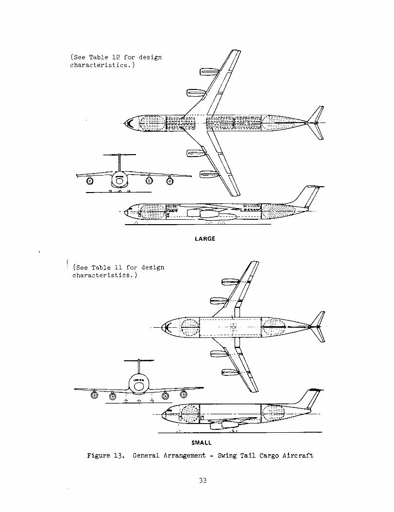
(See Table 12 for designcharacteristics.)
LARGE
(See Table ii for design
characteristics.)
SMALL
Figure 13. General Arrangement - Swing Tail Cargo Aircraft
33
In the swing tailairplane design, access to the cargo compartment is provided
by swinging the tail horizontally around a vertical hinge line. The entire
empennageand aft fuel tank is included in the structure which must be movedto
provide for loading of the cargo through the aft end of the airplane. The center
fuselage, which contains the cargo compartment, is pressurized and has a domeon
either end. The flight station is also pressurized but it is separated from the
cargo compartmentby an unpressurized area containing the forward LH2 tank. Thedesign does not provide for in-flight access to the cargo compartment.
The two configurations of liquid hydrogen fueled cargo aircraft were compared
on the basis of terminal operational environment compatibility, maintenance, safety,and performance.
The cargo terminal operational environment envisioned for 1990 - 1995 is one
of maximumautomation. Aircraft will be positioned at gate areas adjacent to fixed
base cargo terminals. The nose loader configuration is Judged to be more com-
patible with this concept of cargo terminal than is the swing tail. With the nose
visor door open, that aircraft can be taxied directly into position to mate with the
conveyor system of the cargo terminal. However, because the swing tail aircraft
must be loaded from the aft end, ground equipment would be required to move that
airplane into proper position for automatic loading after the empennagesection has
been rotated to provide access to the cargo compartment. This would require bothextra ground-based equipment and additional time.
Analysis of aircraft maintenance operations also indicates a preference for the
nose loader configuration. Removalof the forward hydrogen tank of the swing tail
aircraft for inspection and/or maintenance requires that a break-joint be provided
in the fuselage structure. Separation of the fuselage sections at this joint then
would permit the tank to be removed. This separation of the fuselage, and subse-
quent remating on completion of tank maintenance, would require complex ground sup-
port equipment. The requirement for control and fuel feed lines to span the hinge
Joint of the aft fuselage on the swing tail aircraft also adds to the routine
maintenance tasks of that configuration. In the case of the nose loader design,
access to the fuselage upper lobe tanks would be provided by removable structural
panels. These panels would be located along the crown of the upper lobe. After
removal of the panels the tanks could be hoisted vertically for removal. The aft
fuselage tank could be removedthrough fuselage lower surface doors.
34
In the area of safety, the nose loader is again the preferred design. The
major portion of the hydrogen fuel is contained in tanks above the cargo compart-
ment which offers some degree of protection to the tanks should the aircraft be
involved in an accident during takoff or landing. The hinge Joint of the swing
tail aircraft is a potential source of hydrogen gas leaks and therefore a source
of potential safety hazard. As noted above, hydrogen fuel lines must span this
Joint and are subject to abuse each time the aft fuselage is rotated.
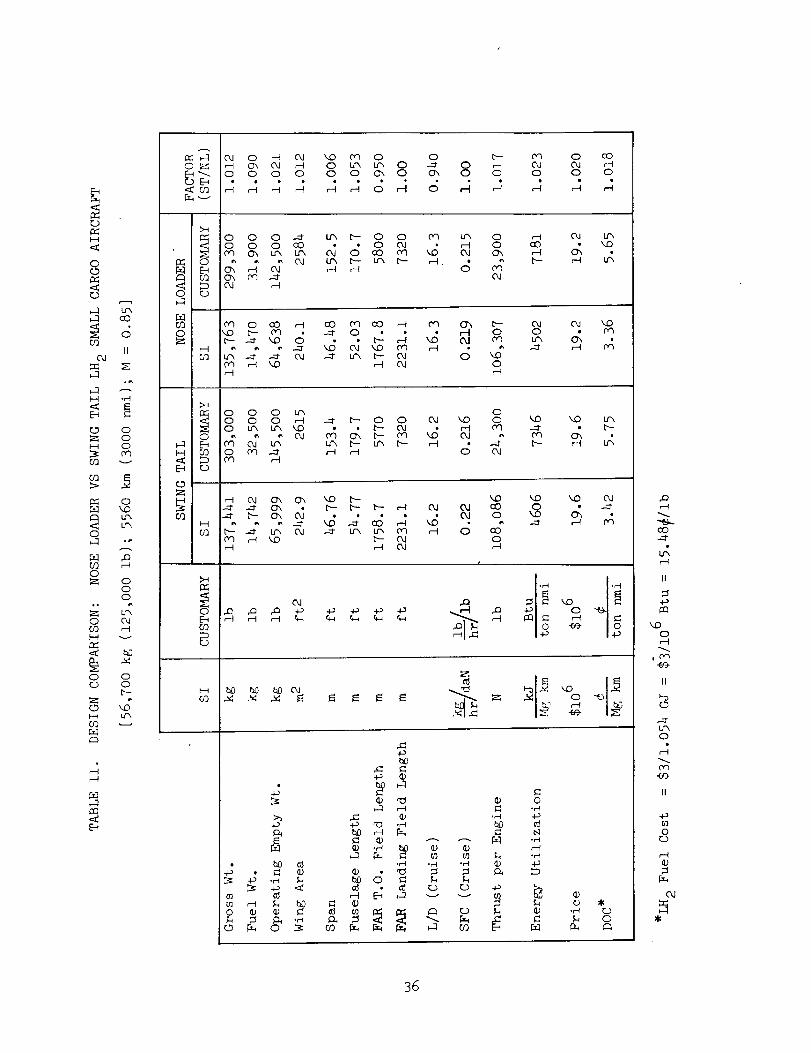
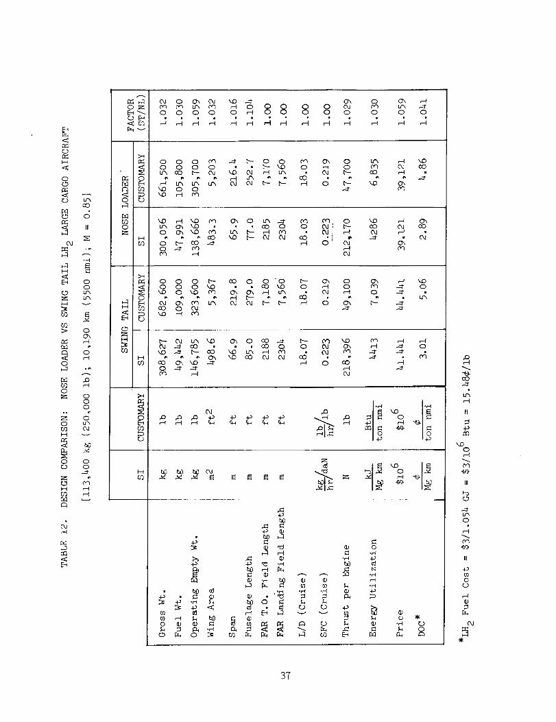
Comparisons of performance and design characteristics of the nose loader and
swing tail hydrogen-fueled aircraft are given in Tables ii and 12 for the small
and large missions, respectively. The column labeled "factor" in both of these
tables gives a direct comparison of each parameter listed using the nose loader
as the base. Inspection of these data shows the nose loader configuration to be
preferred in nearly all instances.
In summary, the nose loader configuration of LH 2 cargo aircraft was found
to offer advantages in all areas of comparison_ terminal operational environment,
maintenance, safety, and performance. Accordingly, it was selected as the LH 2
configuration to be compared to the hydrocarbon fueled (Jet A) reference cargo
aircraft.
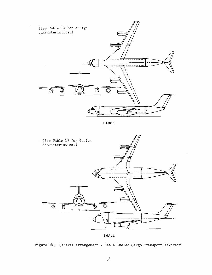
3.3.3 Reference (Jet A) Cargo Aircraft
The general arrangements of the Jet A-fueled cargo aircraft are illustrated
in Figure 14. The configurations are essentially the same as that previously
described for the hydrogen-fueled nose loader design with the following general
exceptions:
• Fuel storage is relocated from fuselage tanks to wing tanks, thus
providing structural load relief for the wing.
• The upper fuselage hydrogen tank storage lobe is removed, although
the basic fuselage diameter is the same.
• The large aircraft uses a high-wing position rather than the mid-wing
position on the large hydrogen aircraft.
This latter change stems from a basic structural difference between the
aircraft designed for the two fuels for the large mission. The double lobe type
fuselage shape of the hydrogen aircraft with its structural tie at the intersection
B5
<
o
l-d<
0¢D
<_D
_-1 u'x_-l cO
su?
IIod
°_
_.1 .H
_ (23
;>
u",o
O
o(23
o or..) o
zo ,ZCO _
C3
A
E__ _ _ o _ _ 0 _ 0
o o o 0 o o _ 0 _ 0 o
o_ o cooJ o_o o o
o o o _ _ _ o o _ _ oo o o _ -- _ o _ • _ o _ 4
r_ 0"I 0 cO _ cO oq co _ O_ _ b-
0 _0 b- O_ --_ 0 • r-I 0o"1OJ
Dq _ kO r-t O_ 0
O_ OJ kD
4_r H r_
o o o b_ 00 0 0 _ _ _ 0 0 O_ _D 00 b_ I._ kO _ OJ r-I
kO kO u-_
4
o'_ _ 0'_ O_ , 0,.I 0
o_
B
F--IO_
0'I _-_ _ _-- _ 0r-I _ C_ _-I
eJ
kO OJ0 4
•H °_-I
o _ o
t_
o o •
+_
_0
• _ o
• .H
H _ C
• .H bO • O
•H ,H .H o
o
.H
o
oo
•H ED
r-_
O0
r-_
II
kO0
,0"_
II
U'X0
O_
oo
o
od
5
36
CD
H
00
C.) Lr_O0
F_
OJ
°r-._
E_ OO
Z u_
00 i_ o
_ ,---t
oo
o_ o
oo
o _
H _
O Or...) O
Z "
H _
Ct_
a_
_:_ :-3 C_l o c_. oJ _oZ ('_ c_ Lr'X c,q ,--tO Q O_ o o o o o ,._ o o O o
L_0 0 0
o o o 0'_ _ _- o o
. o o o o ° _ _DI_ 0 _ _ _ _ L_
_ CO kid O O
c,q O_ oo ,-t o
co ,-4
0q
_ _ _ _ _ o _ _ _ _ o
_ _ _ _ o o _ro __ __ _, _O _ _ _ _ O IO _ _
_OCO04
,-t C_O,J cO
O_
0 0 0 _ CO 0 0 0 b- C_ 0
_D 0 _ D"_ (_ _ 00 _D 0 ,-t 00 ,', _ ,"H b- " O0 ,',
0
0", ."-1 ",,0Oh _ 00 --t"
_-- .-.1"
I_ _- 0_ Lr_ _ C_ 0 COa_ ._ cO
H
o .._ _
o _ (D',
_d ¢_ on'_ 0 co
0_
,-4 r-I.-_ o
.-=t
Hr_
,_ _ oca_ ° _4._
_ O
4-_
0 • (1.) _ _._ _ _ _0 _ 0 tO
,._,._
_-_
:-_ ,-__; .,--_
o
b_.el
.el
o.._
o
0
co
_X
II
o
Dq
II
Lf_0
II
-omo
r..)
(xl
3T
(See Table 14 for design
characteristics.)
LARGE
(See Table 13 for design
characteristics.)
SMALL
Figure 14. General Arrangement - Jet A Fueled Cargo Transport Aircraft
38
of the two lobes is compatible with the mid-wing position. However, the fuselage
shape of the Jet A aircraft with its unbroken upper fuselage structural rings is
not readily adaptable to the mid-wing position and must therefore use the high-
wing position. Both the LH 2 and the Jet A-fueled aircraft designed for the small
mission use the low wing position for ease of landing gear attachment.
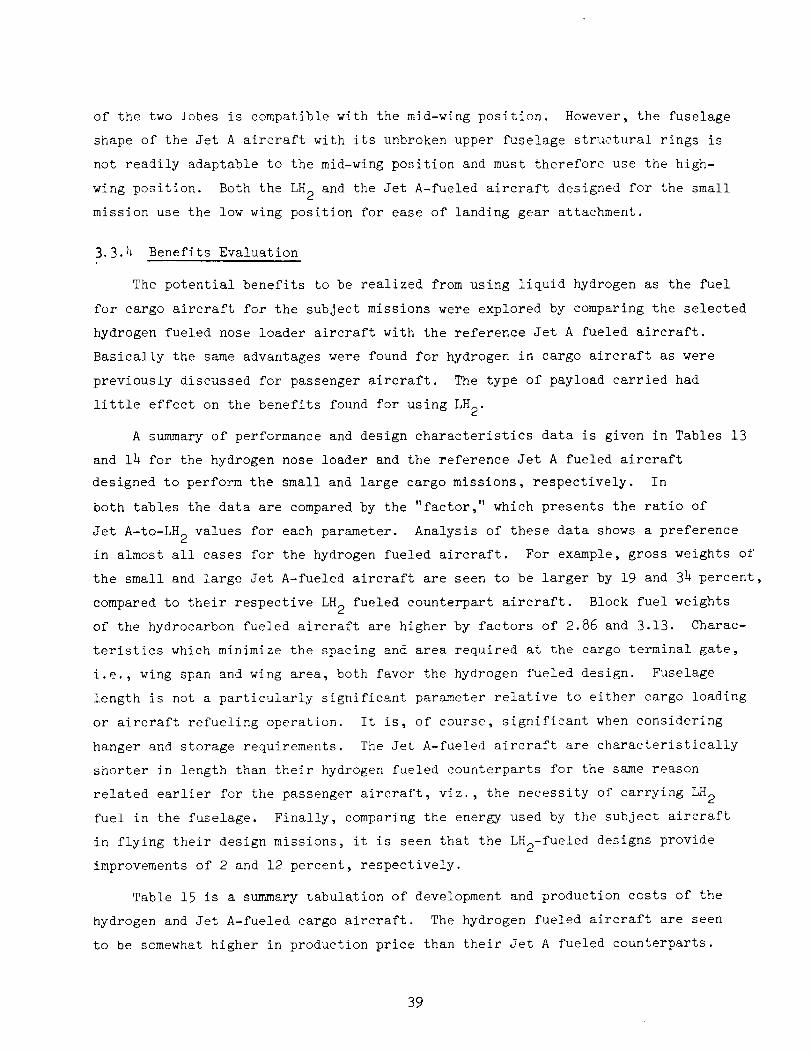
3.3.4 Benefits Evaluation
The potential benefits to be realized from using liquid hydrogen as the fuel
for cargo aircraft for the subject missions were explored by comparing the selected
hydrogen fueled nose loader aircraft with the reference Jet A fueled aircraft.
Basically the same advantages were found for hydrogen in cargo aircraft as were
previously discussed for passenger aircraft. The type of payload carried had
little effect on the benefits found for using LH 2.
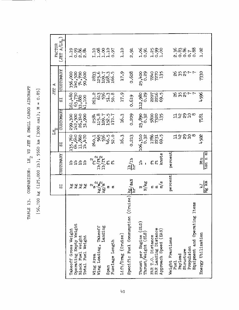
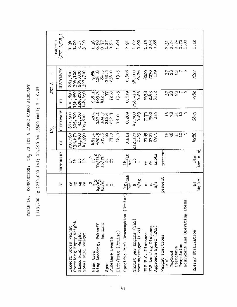
A summary of performance and design characteristics data is given in Tables 13
and 14 for the hydrogen nose loader and the reference Jet A fueled aircraft
designed to perform the small and large cargo missions, respectively. In
both tables the data are compared by the "factor," which presents the ratio of
Jet A-to-LH 2 values for each parameter. Analysis of these data shows a preference
in almost all cases for the hydrogen fueled aircraft. For example, gross weights of
the small and large Jet A-fueled aircraft are seen to be larger by 19 and 34 percent,
compared to their respective LH 2 fueled counterpart aircraft. Block fuel weights
of the hydrocarbon fueled aircraft are higher by factors of 2.86 and 3.13. Charac-
teristics which minimize the spacing and area required at the cargo terminal gate,
i.e., wing span and wing area, both favor the hydrogen fueled design. Fuselage
length is not a particularly significant parameter relative to either cargo loading
or aircraft refueling operation. It is, of course, significant when considering
hanger and storage requirements. The Jet A-fueled aircraft are characteristically
shorter in length than their hydrogen fueled counterparts for the same reason
related earlier for the passenger aircraft, viz., the necessity of carrying LH 2
fuel in the fuselage. Finally, comparing the energy used by the subject aircraft
in flying their design missions, it is seen that the LH2-fueled designs provide
improvements of 2 and 12 percent, respectively.
Table 15 is a summary tabulation of development and production costs of the
hydrogen and Jet A-fueled cargo aircraft. The hydrogen fueled aircraft are seen
to be somewhat higher in production price than their Jet A fueled counterparts.
39
I_-..1O__._r..D
C)'XO'XXO .__- 0 _ x.O ,,-I,-I o_ ,-I C_ 0 0"_
dc_dd _AAAd ,_ d dd
t.r_ C_ k(D C,"_ O0b-00 0
AdA c_dddd A
< Lr_
OOOO c_D b--c_u_ O_ CO
O O ('O OOO
O _ O _D _.O ,-I
r..)
8_ o__¢, ,o ¢,_,_-_- o('_ (kl ('_ O,.I ('_
L_O_
r-I C") _ "_ O..I
,--t O'_--t
u'_ _ u", u",t_--- t"_- _O,-I OJ _,') O,J Oh
d c_c_c_H
<
0
<r...)
d
II
ooo
oooo _._._._- ,_ o_ ,_0 0-_I- 0 • 0oq Lr_ r-IC_ Lr_ U'_C)_ O_ 0 _ OJ
_ _ _ OJ _ O t.l'X_"- ,--I
O,J OO U'_ _.z._ °_°0°o3,-4 O__03 O O,J (v_
<
CO
v
oko
0_
O OO O ,-I LfkkO L_ O (v_ 0-3 O _.1O Lr'_ t_D cu _,D (_1 ('_
_ _ ,_ _ _ .__1-u_ ,-1 (_ _O
,-I ,-4
L_,-t _r_ OhO00c_o_ u_,-IO.I_D
ckJ
O
u'h
L_X
.m
,.or-I
oo
OE_0_
_ _ o_ _--._ _ ,
!'_
O,4o
coHfl=<
OG)
Om
o,/r-q
v
HCt')
0
E_
00
L_X
-I_ ._I.rl -ID
_ _ ._ _-_
bD
o_
.rl
r..)
o
4._ o1
_._ _ _r_
° c;_=.•_ _ _ E-_._ 0
(_
i-i
.t-I
0 _
._ _
c)
v
¢,30_b-_Ch 0 O_ O4OJ eqCOrq ChGO
,-i J cJ o4OOOr-_
O4
<L_CO
<
¢o8888 _3_._. _. _' _ 8_E-I m'_D Lr_ b_ J-I O4O4 0 oO
,._ co Oco O4 L_com_mo
oo_ b-c0 ¢_ b-- u'_0q o4 o4
t'--
r_)
H<
oo
J
II
°_
I-4O3
0 0 8 0 r-I0qLr_ Lr_ O_ O_D OO OqOJ
o_
_q O4 O4
P_
c_
oo
v
OO8o _-_._ o o _-o__ ¢" " 0_no o4 . __ _
_ Or_
_D
E_
>
OJ
_q
O
H
kOcD
r_
E_
OC_
O
4D
OOO
OLr_
O4v
b_
OO
O'3
H
_C) • • _-I O4 •O_O Oq _O Lr_ b-- oO OJ _-I • _-I oqO_
C_ 0_1_. _00 e_J__LO_ _ ,"4 _v O4_0 _ O4_
C_r-I O4
'_D CO ,.-I 0 t.r_,'-I on o") ,-'l
o
_ _ _._ _ 0
bOb_ bO t_O bfl O4 O48O4_. _ _ •
_0 _
o ,.__ _ ,-_ "d
-P .H _ .__
_ F'_Ir_I _.I ._
_._ _,'_o o_0
o
o -.Pv I_1
0
rO .H v ,_I 0
_£ ._ _ o o_
o
0.,-.I
_-_
%
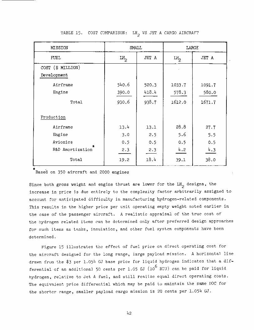
TABLE 15. COST COMPARISON: LH 2 VS JET A CARGO AIRCRAFT
_SSION
FUEL
COST ($
Development
Airframe
Engine
Total
Production
Airframe
Engine
Avionics,
R&D Amortization
Total
SMALL LARGE
LH2 JETA L_ JETA
540.6
39O.0
930.6
13.4
3.0
0.5
2.3
19.2
520.3
418.4
938.7
13 .i
2.5
0.5
2.3
18.4
1033.7
578.3
1612.0
28.8
5.6
0.5
4.2
39.1
i091.7
580.0
1671.7
27.7
5.5
0.5
4.3
38.0
Based on 350 aircraft and 2000 engines i
Since both gross weight and engine thrust are lower for the LH 2 designs, the
increase in price is due entirely to the complexity factor arbitrarily assigned to
account for anticipated difficulty in manufacturing hydrogen-related components.
This results in the higher price per unit operating empty weight noted earlier in
the case of the passenger aircraft. A realistic appraisal of the true cost of
the hydrogen related items can be determined only after preferred design approaches
for such items as tanks, insulation, and other fuel system components have been
determined.
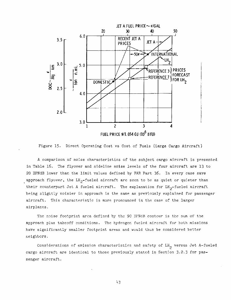
Figure 15 illustrates the effect of fuel price on direct operating cost for
the aircraft designed for the long range, large payload mission. A horizontal line
drawn from the $3 per 1.054 GJ base price for liquid hydrogen indicates that a dif-
ferential of an additional 50 cents per 1.05 GJ (106 BTU) can be paid for liquid
hydrogen, relative to Jet A fuel, and still realize equal direct operating costs.
The equivalent price differential which may be paid to maintain the same DOC for
the shorter range, smaller payload cargo mission is 20 cents per 1.054 GJ.
42
<.)O
3.5 -
3.0 -
2.,5-
2.0-
6.0
.5.0
.e-,
3.0
ooM /. /
JETA FUEL PRICE,---,¢IGAL
20 30 40 50
.FORECAST
_ - REFERENCE.7IiFOR LH2
1 2 3 4
FUEL PRICE $/I.054GJ (106BTU)
Figure 15. Direct Operating Cost vs Cost of Fuels (Large Cargo Aircraft)
A comparison of noise characteristics of the subject cargo aircraft is presented
in Table 16. The flyover and sideline noise levels of the four aircraft are 13 to
20 EPNdB lower than the limit values defined by FAR Part 36. In every case save
approach flyover, the LH2-fue!ed aircraft are seen to be as quiet or quieter than
their counterpart Jet A fueled aircraft. The explanation for LH2-fueled aircraft
being slightly noisier in approach is the same as previously explained for passenger
aircraft. This characteristic is more pronounced in the case of the larger
airplanes.
The noise footprint area defined by the 90 EPNdB contour is the sum of the
approach plus takeoff conditions. The hydrogen fueled aircraft for both missions
have significantly smaller footprint areas and would thus be considered better
neighbors.
Considerations of emission characteristics and safety of LH 2 versus Jet A-fueled
cargo aircraft are identical to those previously stated in Section 3.2.3 for pas-
senger aircraft.
43
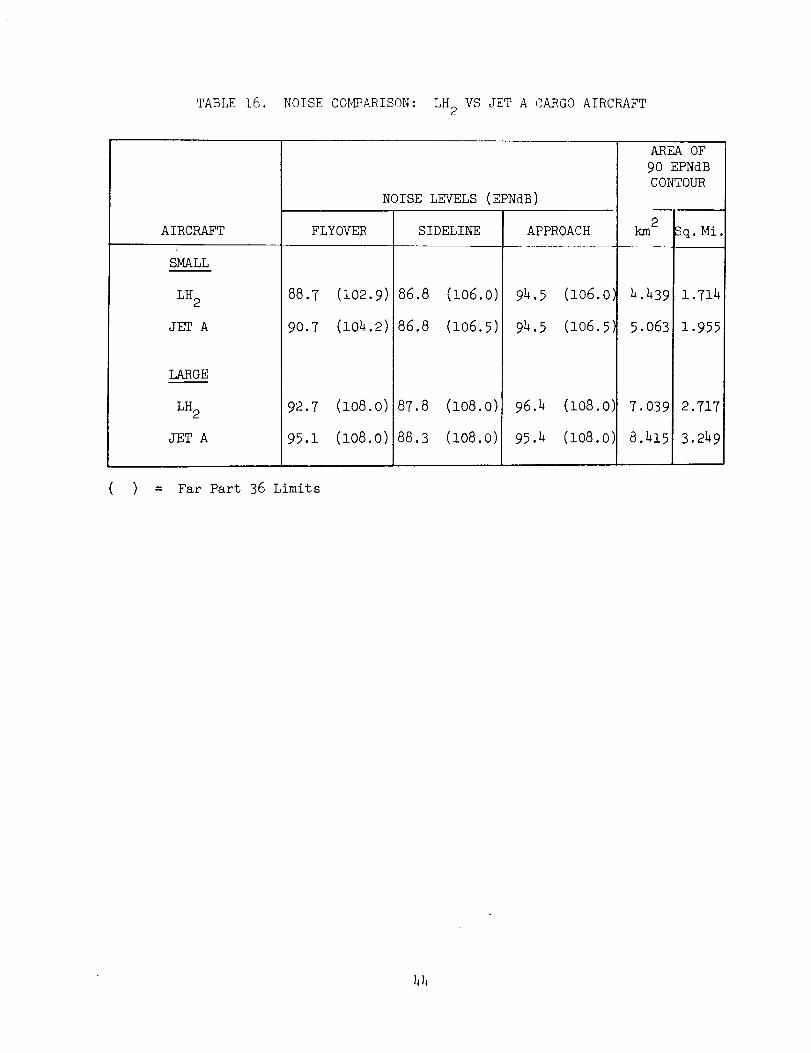
TABLE 16. NOISE COMPARISON: LH 2 VS JET A CARGO AIRCRAFT
AIRCRAFT
SMALL
LH 2
JET A
lARGE
LH 2
JET A
FLYOVER
88.7 (102.9)
90.7 (104.2)
NOISE LEVELS (EPNdB)
SIDELINE
94.5
94.5
96.4
95.4
86.8 (lO6.O)
86.8 (lO6.5)
92.7 (108.0)
95.1 (108.0)
87.8 (108.0)
88.3 (i08.0)
APPROACH
(106.0
(106.5
(io8.o)
(lO8.O)
AREA OF
9O EPNdB
CONTOUR
km 2 Sq. Mi
4.439 1.714
5.063 1.955
7.039 2.717
8.415 3.249
( ) = Far Part 36 Limits
42
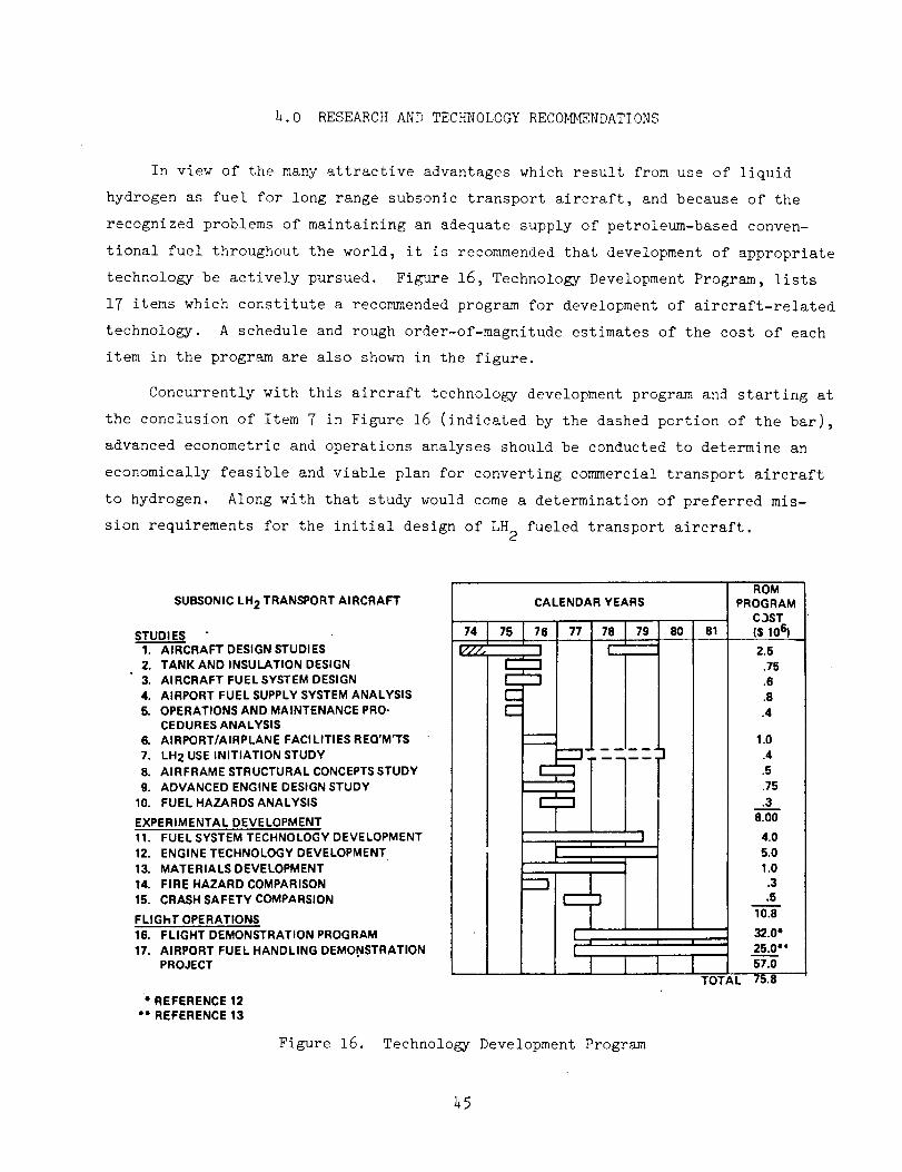
h.0 RESEARCH AND TECHNOLOGY RECOMmeNDATIONS
In view of the many attractive advantages which result from use of liquid
hydrogen as fuel for long range subsonic transport aircraft, and because of the
recognized problems of maintaining an adequate supply of petroleum-based conven-
tional fuel throughout the world, it is recommended that development of appropriate
technologybe actively pursued. Figure 16, Technology Development Program, lists
17 items which constitute a recommended program for development of aircraft-related
technology. A schedule and rough order-of-magnitude estimates of the cost of each
item in the program are also shown in the figure.
Concurrently with this aircraft technology development program and starting at
the conclusion of Item 7 in Figure 16 (indicated by the dashed portion of the bar),
advanced econometric and operations analyses should be conducted to determine an
economically feasible and viable plan for converting commercial transport aircraft
to hydrogen. Along with that study would come a determination of preferred mis-
sion requirements for the initial design of LH 2 fueled transport aircraft.
SUBSONIC LH2 TRANSPORT AIRCRAFT
STUDI ES1. AIRCRAFT DESIGN STUDIES2. TANK AND INSULATION DESIGN
3. AIRCRAFT FUELSYSTEM DESIGN4. AIRPORT FUEL SUPPLY SYSTEM ANALYSIS5. OPERATIONS AND MAINTENANCE PRO-
CEDURES ANALYSIS6. AIRPORT/AIRPLANE FACILITIES REQ'M_TS
7, LH2 USE INITIATION STUDY8. AIRFRAME STRUCTURAL CONCEPTS STUDY9. ADVANCED ENGINE DESIGN STUDY
10. FUEL HAZARDS ANALYSIS
EXPERIMENTAL DEVELOPMENT11. FUEL SYSTEM TECHNOLOGY DEVELOPMENT
12. ENGINE TECHNOLOGY DEVELOPMENT13. MATERIALS DEVELOPMENT
14. FIRE HAZARD COMPARISON15. CRASH SAFETY COMPARSION
FLIGHT OPERATIONS16. FLIGHT DEMONSTRATION PROGRAM
17, AIRPORT FUEL HANDLING DEMO.NSTRATIONPROJECT
CALENDAR YEARS
r---_r----I
C
77 7_L__ 80
m
m
---1- ..... ]
I
i JI
*REFERENCE12*" REFERENCE13
Figure 16. Technology Development Program
ROMPROGRAM
C3ST81 ($106)
2.5
.75
.6
.8
.4
1.0.4
.5
.75
.38.00
4.05.0
1.0.3.5
10.8
32.0*25.0*"57.0
TOTAL
25
5.0 CONCLUSIONS
The use of liquid hydrogen as fuel in subsonic transport aircraft results
in designs which are lighter, have smaller wings but larger fuselages, require
smaller engines, can operate from shorter runways, minimize pollution of the
atmosphere, and expend less energy in performing their missions than correspond-
ing designs fueled with conventional hydrocarbon (Jet A). Depending on the payload-
range design requirement, the cost of liquid hydrogen can be between 20¢ and 50¢
greater per 1.054GJ (106 Btu), relative to Jet A cost, and the LH2-fueled aircraft
can still provide equal or lower direct operating cost.
The preferred design concepts for hydrogen-fueled passenger and cargo transport
aircraft evolved in this study have conventional appearance. Unusual configurations
which were investigated to see if use of the new fuel would offer unique design
possibilities proved to be flawed for the subject missions. Designs configured
to provide specific advantages developed serious problems in other respects such
that the net result was unsatisfactory.
The problems of designing and developing practical, realistic transport air-
craft fueled with liquid hydrogen which can meet airline standards for maintenance,
operations, and utilization in both passenger and cargo application, require tech-
nology development but are not dependent upon either a breakthrough in capability
or invention of new products for success. Thus, it is considered technically
feasible that hydrogen-fueled transport aircraft can be developed and ready to
begin commercial operations by 1990. This allows i0 years for design and develop-
ment of a production aircraft, assuming a one year overlap with the Technology
Development Program of Section 4. However, the following significant conditions are
recognized as mandatory and supplemental to the aircraft-related technology require-
ments in order to achieve this goal:
• A national (and international) commitment must be made to develop
hydrogen for widespread use, and commercial transport aircraft must be
mandated to use it.
• Hydrogen manufacture and distribution systems must be developed and
implemented.
• Facilities must be provided at selected airports to liquify, store,
and handle hydrogen.
46
REFERENCES
i. Cook, Earl, "The Flow of Energy in an Industrial Society," Scientific
American, September 1971, p135.
2. Transportation Energy Panel, "Research and Development Opportunities for
Improved Transportation Energy Usage," Department of Transportation,
DOT-TSC-OST-73-14, Sept. 1972.
3. Michel, J. W., "Hydrogen and Exotic Fuels," Oak Ridge National Laboratory,
0RNL-TM-4461, June 1973.
4. Keller, C. W., "Fiberglass Supports for Cryogenic Tanks," NASA CR 120937,
Lockheed Missiles and Space Co., LMSC - D281476, i0 October 1972.
5. Brewer, G. D., "Advanced Supersonic Technology Concept Study - Hydrogen
Fueled Configuration," NASA CRI14,718, prepared by the Lockheed California
Company under Contract No. NAS 2-7732, January 1974.
6. Bill Henzey's Airline Reports, P5, October 28, 1974, Wm V. Henzey and
Associates, Washington, D.C.
7. Johnson, J. E., "The Economics of Liquid Hydrogen Supply for Air Trans-
portation," Advances in Cryogenic Engineering, p12, Vol. 19, edited by
K. D. Timmerhaus, Plenum Press, New York, 1974.
8. Brines, G. L., "Studies for Determining the Optimum Propulsion System
Characteristics for use in a Long Range Transport Aircraft," NASA
CR-120950, 1972.
9. Anon, "Propulsion System Studies for an Advanced High Subsonic Long Range
Jet Commerical Transport Aircraft," NASA CR-121016, 1972.
i0. Grobman, Jack; Norgren, Carl; and Anderson, David; Turbojet Emissions,
Hydrogen Versus JP. NASA TM-X-68258, 1973.
ll. Grobman, Jack; and Ingebo, Robert D., Jet Engine Exhaust Emissions for
Future High Altitude Commerieal Aircraft. NASA TM-X-71509, 1974.
12. "The Energy Dilemma and Its Impact on Air Transportation," NASA/ASEE 1973,
NASA-Langley Research Center and Old Dominion University.
13. Dixy Lee Ray Committee, "Report to the President on Energy Research and
Development," Appendix E-2, dated Oct 27, 1973.
47