Embed Size (px)
Citation preview

NASA CONTRACTORREPORT
NASA CR-129037
(NASA-CR-12903 7 ) PHYSICAL FORCES N75-101 1 7
INFLUENCING SKYLAB EXPERIMENTS M551, M552,AND 553 Summary Report (Lockheed
Missiles and Space Co.) 77 p HC $4.75 UnclasCSCL 22C G3/12 51124 I
PHYSICAL FORCES INFLUENCING SKYLAB
EXPERIMENTS M551, M552, and M553
Summary ReportBy S. V. Bourgeois
Lockheed Missiles and Space Company, Inc.Huntsville, Alabama
January 1974
Prepared for
NASA-GEORGE C. MARSHALL SPACE FLIGHT CENTER
Marshall Space Flight Center, Alabama 35812
https://ntrs.nasa.gov/search.jsp?R=19750002045 2018-08-20T17:05:09+00:00Z

TECHNICAL REPORT STANDARD TITLE PAGEI. REPORT NO. 2. GOVERNMENT ACCESSION NO. 3. RECIPIENTS CATALOG NO.
NASA CR-1290374 TITLE AND SUBTITLE 5. REPORT DATE
Physical Forces Influencing Skylab Experiments January 1974M551, M552 and M553 6. PERFORMING ORGANIZATION CODE
7. AUTHOR(S) 8.PERFORMING ORGANIZATION REPORT #S. V. Bourgeois TR D390056
1, PERFORMING ORGANIZATION NAME AND ADDRESS 10. WORK UNIT NO.
Lockheed Missiles and Space Company, Inc. 1. CONTRACT OR GRANT NO.Huntsville, Alabama NAS 8-27015
13. TYPE OF REPORT & PERIOD COVERED
12. SPONSORING AGENCY NAME AND ADDRESS
National Aeronautics and Space Administration Contractor ReportWashington, D.C., 20546Washington, D.C.,14. SPONSORING AGENCY CODE
15. SUPPLEMENTARY NOTES
16. ABSTRACT
This report summarizes the physical forces influencing Skylab experimentsM551, M552 and M553 and was compiled under Contract NAS8-27015. This effort wasperformed by the Lockheed-Huntsville Research and Engineering Center for NASA-Marshall Space Flight Center.
The NASA Contracting Officer's Representative (COR) for this study is Mr.T. C. Bannister, S&E-SSL-T. The NASA principal investigators for this study areMr. R. M. Poorman (M551), S&E-ASTN-MM; Mr. J. R. Williams (M552), S&E-PT-M; andMr. E. A. Hasemeyer (M553), S&E-PT-MWM.
The author also acknowledges the other investigators whose results con-tributed to this report: C. M. Adams, University of Wisconsin; M. R. Brashears,Lockheed Missile & Space Company; D. N. Braski, Union Carbide Corporation;J. L. Brown, Georgia Institute of Technology; P. C. Johnson, A. D. Little Company;T. Z. Kattamis, University of Connecticut; D. J. Larson, Grumman Aerospace Corpo-ration; K. Masubuchi, Massachusetts Institute of Technology; R. E. Monroe, BattelleMemorial Institute; J. M. Tobin, Westinghouse Electric Corporation; and W. A. Zisman,Naval Research Laboratory.
7. KEY WORDS 18. DISTRIBUTION STATEMENT
Unclassified - Unlimited
19. SECURITY CLASSIF. (of this report) 20. SECURITY CLASSIF. (of this page) 21. NO. OF PAGES 22. PRICEUnclassified Unclassified 76 NTIS
MSFC- Form 3292 (Rev December 1972) For sale by National Technical Information Service, Springfield, Virginia 22151

FOREWORD
This report summarizes the physical forces influencing Skylabexperiments M551, M552 and M553 and was compiled under ContractNAS8-27015. This effort was performed by the Lockheed-HuntsvilleResearch & Engineering Center for NASA-Marshall Space FlightCenter.
The NASA Contracting Officer's Representative (COR) forthis study is Mr. T. C. Bannister, S&E-SSL-T. The NASA princi-pal investigators for this study are Mr. R.M. Poorman (M551),S&E-ASTN-MM; Mr. J.R. Williams (M552), S&E-PT-M; andMr. E.A. Hasemeyer (M553), S&E-PT-MWM.
The author also acknowledges the other investigators whoseresults contributed to this report: C.M. Adams, University ofWisconsin; M.R. Brashears, Lockheed Missiles & Space Company;D. N. Braski, Union Carbide Corporation; J. L. Brown, GeorgiAInstitute of Technology; P.C. Johnson, A.D. Little Company;T. Z. Kattamis, University of Connecticut; D. J. Larson, GrummanAerospace Corporation; K. Masubuchi, Massachusetts Institute ofTechnology; R.E. Monroe, Battelle Memorial Institute; J.M. Tobin,Westinghouse Electric Corporation; and W.A. Zisman, NavalResearch Laboratory.
PRECEDING PAGE BLANK NOT FILMED
iii

TABLE OF CONTENTS
Page
FOREWORD iii
NOMENCLATURE ix
SECTION I. INTRODUCTION 1
SECTION II. M551 METALS MELTING EXPERIMENT 5
A. Convection Analysis 5
B. Weld Pool Splattering 8
C. Gravity Effects on Spiking 9
D. Beading Considerations 12
E. Dwell Shape 16
F. Surface Tension Measurements 16
G. Conclusions 19
SECTION III. M552 EXOTHERMIC BRAZING EXPERIMENT 20
A. Capillary Flow 21
B. Bubble Dynamics 26
C. Capillary Pumping in Tapered Gaps 27
D. Surface Tension Measurements 29
E. Flight Results 31
F. Conclusions 32
SECTION IV. M553 SPHERE FORMING EXPERIMENT 34
A. Convection Analysis 34
B. M553 Trajectory Analysis 44
C. Conclusions Based on TrajectoryComputations 47
D. Shape Dynamics 51
E. Surface Tension Measurements 55
F. Shrinkage Forces 55
PRECEDING PAGE BLANK NOT FILMED
V

TABLE OF CONTENTS (Continued)
Page
SECTION IV. Continued
G. Flight Results 58
H. Conclusions 60
REFERENCES 61
ACKNOWLEDGEMENTS 65
LIST OF ILLUSTRATIONS
Figure Title Page
1 Spiking Mechanism in Electron Beam Welding 10
2 Karman Vortex Street (Diagrammatic);Streamlines Drawn in a System of CoordinatesMoving with the Vortex Street 13
3 Strouhal Number vs Reynolds Number 14
4 Proposed M551 Dwell Pool Behavior 17
5 Cross Section of Aluminum Dwell Region 18
6 Cross Section of Stainless Steel Dwell Region 18
7 M552 Configuration 22
8 Tapered Gap Capillary Pumping for the M552Experiment 28
9 Surface Energy vs Temperature Ag-Cu SolderAlloys. A1 2 0 3 Substrate, Argon Atmosphere 30
10 Trajectory Sequence - March 1972 KC-135 Flight(Nickel) 52
11 Unstrained Outer Casting and HomogeneousNucleation of Residual Liquid Under ExtremeNegative Pressures 56
vi

LIST OF ILLUSTRATIONS (Continued)
Figure Title Page
12 State of a Solidifying Spherical Casting withExterior Shell Deformation 56
13 Hydrostatic Tensions in the Liquid Core of 1 cmRadius Castings of Aluminum, Copper, Nickel,and Iron Calculated from the Creep Model 57
LIST OF TABLES
Table Title Page
1 M551 Dimensional Analysis 7
2 Bead Population 14
3 Bead Spacing 15
4 M552 Spreading Times 23
5 M552 Flow Velocities 23
6 M552 Reynolds Numbers 24
7 Probable Characteristic Velocities in ElectronBeam Melting 41
8 M553 Dimensional Analysis 43
9 Total Force Due to Electron Beam 46
10 Temperature Distribution at 3.0 Seconds 48
11 Temperature Distribution at 3.5 Seconds 49
12 Summary of Vaporization Force Calculation 50
13 Formation Times for M553 Materials 54
14 Frequency for M553 Materials 54
15 Decay Time for M553 Materials 54
16 Work of Adhesion (WA) for Nickel and its Alloyson A 2 0 3 (x 10 - 5 N/cm) 55
17 M553 Surface Velocity Measurements 59
vii

NOMENCLATURE
A Area
B Magnetic Induction
C Heat Capacity
c Concentration, Mass or Moles per Unit Volume
D Diameter, Diffusivity, Displacement Current
d Differential Operator
E Electric Field Intensity
e Base of Natural Logarithms
F Force
f Force Component
G Temperature Gradient of the Melt at Solidification Front
g Acceleration of Gravity
gE Sea Level Gravity on Earth, 9.8 m/sec 2
H Magnetic Field Intensity
h Individual Coefficient of Heat Transfer
I Electrical Current Intensity
K Coefficient of Isothermal Volumetric Compressibility,
P aP1a ( )T
k Mass Transfer Coefficient, Thermal Conductivity
L Length
M Molecular Weightw
m Slope of Equilibrium Curve
viii

NOMENCLATURE (Continued)
m Mass Flux Due to Evaporation
N. Mole Fraction of Component i1
n Unit Normal Vector
n. Moles of Component i1
p Pressure, Power, Temperature Rate (oK/sec)
PV Vapor Pressure
p Partial Pressure
Q Rate of Internal Heat Generation
q Heat
q Rate of Heat Flow
R Universal Gas Constant, Resistance, Outer Radius,
Crystal Interface Growth Rate
r Radius
S Surface Tension Gradient with Temperature
T Temperature
TM Melting Point
AT Degree of Undercooling
t Time
U Internal Energy
u Longitudinal Component of Local Velocity, Velocity inGeneral
V Volume
VVelocity Vector
v Lateral Component of Local Velocity, Nominal Velocity
ix
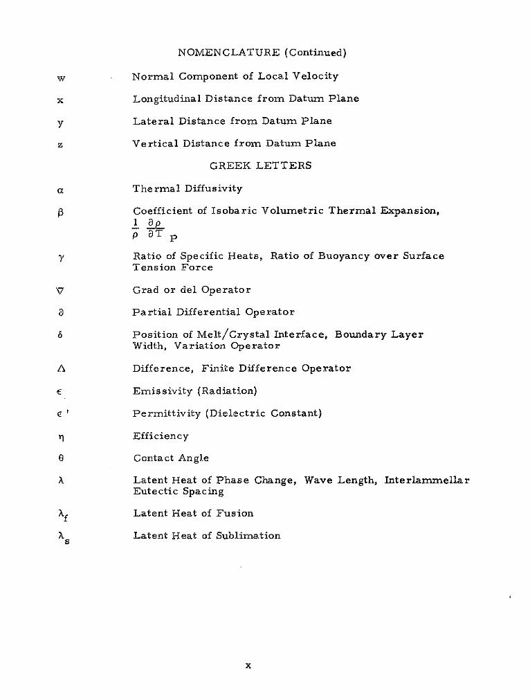
NOMENCLATURE (Continued)
w Normal Component of Local Velocity
x Longitudinal Distance from Datum Plane
y Lateral Distance from Datum Plane
z Vertical Distance from Datum Plane
GREEK LETTERS
a Thermal Diffusivity
1 Coefficient of Isobaric Volumetric Thermal Expansion,I app aT P
7 Ratio of Specific Heats, Ratio of Buoyancy over SurfaceTension Force
V Grad or del Operator
a Partial Differential Operator
6 Position of Melt/Crystal Interface, Boundary LayerWidth, Variation Operator
A Difference, Finite Difference Operator
E Emissivity (Radiation)
E ' Permittivity (Dielectric Constant)
11 Efficiency
o Contact Angle
A Latent Heat of Phase Change, Wave Length, InterlammellarEutectic Spacing
Xf Latent Heat of Fusion
X Latent Heat of Sublimations
x

NOMENCLATURE (Continued)
X Latent Heat of Vaporizationv
A Viscosity
, Magnetic Permeability
V Kinematic Viscosity
P Density, Electrical Resistivity
Pe Electrical Charge Density
U Surface Tension, Stefan-Boltzmann Constant
aLV Surface Energy at Liquid-Vapor Interface
GLS Surface Energy at Liquid-Solid Interface
USV Surface Energy at Solid-Vapor Interface
a' Electrical Conductivity
Angle
Viscous Dissipation
w Frequency, Angular Velocity
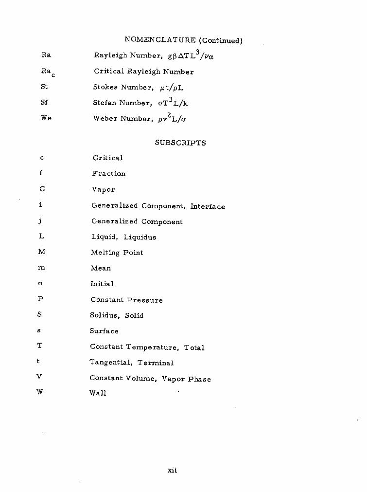
DIMENSIONLESS NUMBERS
Bo Bond Number, pgL 2 /a or pgL 2 /ST
NMI Magnetic Interaction Number, B 2 /L/2p 'ST
Ma Marangoni Number, SATL/pva
Ma c Critical Marangoni Number
Nu Nusselt Number, hL/k
Oh Ohnesorge Number, p/pLST
Pr Prandtl Number, p C/k
xi
NOMENCLATURE (Continued)
Ra Rayleigh Number, gP3ATL 3 /Va
Ra c Critical Rayleigh Number
St Stokes Number, t/pL
Sf Stefan Number, aT3L/k
We Weber Number, pv 2 L/
SUBSCRIPTS
c Critical
f Fraction
G Vapor
i Generalized Component, Interface
j Generalized Component
L Liquid, Liquidus
M Melting Point
m Mean
o Initial
P Constant Pressure
S Solidus, Solid
s Surface
T Constant Temperature, Total
t Tangential, Terminal
V Constant Volume, Vapor Phase
W Wall
xii

NOMENCLATURE (Concluded)
SUPERSCRIPTS
Denotes Vector Quantity
First Derivative with Time
Second Derivative with Time
xiii

SECTION I. INTRODUCTION
This summary report on physical forces is concerned specific-ally with the Metals Melting Experiment, the Exothermic BrazingExperiment, and the Sphere Forming Experiment. They were per-formed in the M512 facility during the Skylab I mission of May-June1973 by Astronaut Charles Conrad. These experiments are de-scribed briefly as follows:
M551 Metals Melting Experiment: Three sample disks, eachcontaining three metal specimens of varying thicknesses, are to berotated automatically at a controlled speed of 2.5 rpm under anelectron beam gun such that an electron beam weld seam is producedin the metal specimen at a radius of 6 cm. Disk materials include2219 aluminum, 321 stainless steel and tantalum. During the con-tinuous weld portion of each disk, both full and partial penetration ofthe disk will be achieved by having a constant power input but a vary-ing disk thickness. For each disk, the continuous weld will befollowed by a dwell portion. In the dwell portion of the weld, thedisk will remain stationary while the electron beam impinges on athick segment of the disk, thus creating a large molten pool. Theelectron beam will then be shut off and the pool will be allowed tosolidify.
M552 Exothermic Brazing: A technique for joining stainlesssteel tubes will be tested in this experiment and the flow and solidi-fication behavior of weightless molten braze alloys will be studied.The joining technique will use a solid mixture that produces heat byexothermic chemical reaction to braze sleeves over 18.75-nmmdiameter tubes, using a copper-silver-lithium braze alloy. A pack-age containing four assemblies, each consisting of a tube with sleeveand preformed braze alloy surrounded by exothermic material, willbe mounted in the M512 facility's vacuum chamber. The exothermicreactions in the four assemblies will be ignited in sequence and thewhole package will be returned to earth for analysis.
M553 Sphere Forming Experiment: Twenty-eight 6.35-mmdiameter spherical specimens will be cast using the electron beamgun as a heat source. The specimens will be initially supported ontwo wheels by a sting. After melting is completed, the spheres willthen be separated from their stings and allowed to solidify whilefree-floating in the vacuum chamber. Specimens will consist of thefollowing materials: pure nickel, Ni-l% Ag, Ni-30% Cu, and Ni-12%Sn.

The M512 facility consisted of a spherical processing chamber,approximately 40 cm in diameter in which several experiments wereperformed. The electron beam in the M512 unit was operated be-tween 50 to 80 mA at 20 kV. A vacuum environment of 10-4 torr wascreated by venting the chamber directly to outer space.
The nature, magnitude and direction of the physical forceswhich influence the experiments are important because they controlthe liquid dynamics of the molten metals. Fluid motions, in turn,affect the melting and solidification of the metals. Thus, the qualityof the processed specimens depends on the physical forces and theirattendant effects on liquid motions.
For these particular Skylab experiments, the only significantdifference between space and earth-processing will be the lack ofgravity. The maximum gravity level experienced during operationof the M551, M552 and M553 experiments aboard Skylab II was7 x 10 - 4 gl (gE = 9.8 m/sec 2 ). Other environmental factors whichmay also differ from earth processing are the vacuum, radiation,electromagnetic and thermal conditions.
Gravity has no direct effect on grain structure or other prop-erties of solidified material. These properties are determined bythe crystallization kinetics which are controlled by short-range .intermolecular forces; i.e., the temperature and concentration atthe fluid-solid interface. Gravity has not been shown to have anysignificant direct effect on these forces, but can affect solidificationindirectly through its direct effect on fluid motion. The three majorindirect effects of gravity on solidification are:
* Sedimentation
* Buoyancy-Induced Convection, and
* Hydrostatic Pressure.
In addition to these three very important indirect effects, the lack ofgravity will also afford the study of a more direct effect - the oppor-tunity to obtain homogeneous nucleation. The long free-float timespotentially available in space processing applications will allowmelts to cool and nucleate without the deleterious effects of con-tainer walls. Wall effects are usually very strong in nucleationphenomena and prevent large degrees of supercooling from beingattained in terrestrial processing. These effects are explainedfurther below.
Sedimentation: This effect may be significant whenever hetero-geneous mixtures exist in fluids, such as in monotectic, dispersed-particle, or fiber-reinforced composite casting. The denser of the
2

immiscible materials will tend to settle unless colloidal or electro-static attractions interfere. Also, in supercooled melts, segregationof freshly formed nuclei by gravity would affect the final grain struc-ture. Nonmetallic inclusions, gas bubbles and voids, which usuallyexist in melts, are also distributed nonuniformly by gravity.
Convection: In terrestrial processing, gravity is the primarydriving force for the convection of contained fluids when they aresubjected to thermal or concentration gradients. Temperature gra-dients arise from external heating and cooling, whereas concentra-tion gradients are usually produced internally (Soret effect and soluterejection at interfaces which leads to "constitutional super-cooling").These two gradients can produce density gradients large enough toinduce buoyancy-driven flow. This fluid motion affects the tempera-ture and concentration profiles within the fluid. This subsequentlyalters the shape and rate of movement of the freezing interface, be-cause the kinetics of freezing depend on the local temperature andconcentration. The degree of mixing caused by convection may belarge enough to change the rate of solidification from kinetic to heattransfer or diffusion controlled which could drastically alter thegrain structure. Examples of this convective effect on the transitionsfrom planar to cellular or dendritic growth, from columnar to equi-axed eutectic structures, and from unidirectional to colonied orbanded eutectic structures are cited frequently in the literature.Another effect of gravity-driven convection on solidification processesis that the bulk fluid movement, if rapid enough, can break delicatedendrite arms and therby alter final grain structure. Furthermore,interlamellar spacing in eutectic growth and dendrite arm spacingare dependent on cooling rate which is a strong function of convection.
Hydrostatic Pressure: A body of fluid in a gravity field sustainsa vertical pressure gradient as the bottom fluid must support theweight of the upper fluid. This pressure gradient distorts the shapeof liquids on earth because the shape of a liquid surface is determinedby the surface tension and the internal hydrostatic pressure (and ad-hesion if the liquid wets a solid surface). Distorted drops of liquidwill result in nonsymmetrical solids upon freezing.
Homogeneous Nucleation Effects: Microgravity solidification inthe M553 experiment may lead to containerless freezing which offersthe probability of homogeneous nucleation and attendant large degreesof undercooling. Most of the effects of large undercooling, and thusextremely rapid freezing rates, are beneficial. Increasing theamount of undercooling in an alloy leads to substantial reductions inboth the segregation ratio of alloying elements and of dendrite-armspacings. As a consequence, the rate of homogenization of an alloyincreases with increasing undercooling. Other beneficial effects of
3

undercooling are reduction in grain size, refinement of endogenousinclusions such as silicates and sulfides, and homogeneous distri-bution of porosity. All these factors are beneficial to mechanicaland possibly physical properties of an alloy, such as strength,hardness, electrical resistivity, etc.
The following sections contain separate discussions for eachexperiment on the physical forces and, where applicable, theireffects on molten metal flow and solidification.
4

SECTION II. M551 METALS MELTING EXPERIMENT
This section contains analyses of the physical forces for theM551 experiment. The first section contains an analysis of thedriving forces, magnitude and pattern of natural convective fluidflows which occur in the Metals Melting Experiment. This sectionis followed by a discourse on the possibility of molten pool spatteringdue to the momentum of the impinging electron beam. Next thespiking in the partial penetration zone of the stainless steel samplesis evaluated for gravity effects. This is followed by a discussion onbeading phenomena. Finally expected dwell shape variations andmeasurements of surface forces for stainless steel are given.
A. CONVECTION ANALYSIS
As in the other M512 experiments, the physical forces andattendant fluid dynamics of the M551 experiment are the most impor-tant factors in determining quality of the final product (in this case,the solidified pool, seam and cut produced on various areas of thinmetal disks). Flow patterns in the molten material are important inthese experiments, because all of the materials have low entropiesof fusion [1]. Thus, their solidification (microstructure) is con-
trolled by the rate of heat transfer removal [2], which changes with
the flow field [3 and 4]. The flow will be especially important in
the dwell mode, since a relatively large pool of melt will be created.The degree of flow will also determine the amount of mixing attained.If no or little flow were present, all.heavier components would segre-gate to the bottom of weld zones on earth, but to a much lesser ex-tent in microgravity environments. Fluid flow can also affect theshape of the weld pool [7].
Application of dimensional analysis [5 and 6] to the govern-ing equations for eb welding, coupled with ground-based and KC-135experiments, should enable prediction of the extent of reduction orincrease of motion in the weld pool and/or the change in flow patternin electron beam welding in space. Possible physical forces whichcould induce fluid flow in the M551 experiment, and their causes,include:.
* Effective Gravity Force: Resultant force on weldspecimen due to earth's gravity and centrifugal andcoriolis forces of orbiting spacecraft.
* Lor'entz Force: Electromagnetic forces induced bypassage of the electron beam current through thespecimen.
5

e Electrostriction: Stresses induced when electricalpermittivity changes with density.
* Magnetostriction: Stresses induced when permeabilitychanges with density.
* Electrostatic Force: Caused by presence of excess elec-trical charge (due to beam current and/or thermionicemission).
* Surface Tension: Tangential stresses at vapor-liquidor liquid-liquid interfaces can be induced if surfacetension depends on temperature and/or concentration.Surface tension will also cause pressure gradientsacross curved interfaces.
* Density Differences Accompanying Phase Changes
* Beam Force: Impinging electrons give up theirmomentum.
o Thermal Expansion: Dilation and compression of fluidswhose density changes appreciably with temperature caninduce fluid flow.
* Vibration: Uncontrolled movement due to engine opera-
tion, astronaut motion, particle impacts, etc.
* Centrifugal and Coriolis: Generated by disk rotation.
o Vapor Pressure: Evaporating molecules impartmomentum which leads to normal stresses atvapor-liquid interface.
* Inertia Forces: Tend to sustain induced motions.
* Viscous Forces: Tend to resist driving forces.
The preceding forces, which could influence fluid flow and solidi-fication, appear explicitly in the conservation equations which apply toformation of a molten pool by electron beam heating. These equationsare given in detail in Section IV.
A formal method of determining the controlling physical forcesaffecting fluid flow and solidification in electron beam welding wasintroduced in Section IV. The controlling physical forces are deter-mined by nondimensioning the governing differential equations andperforming an order-of-magnitude comparison on the various dimen-sionless groups which result. The key to successful analysis is inchoosing the proper reference values; i.e., since no freestream velo-city exists, which forces do we equate to estimate a "characteristic"or "typical" velocity. Choosing the proper characteristic velocity isvery important, since the reference time, temperature, etc., usually
6

depend on this velocity. The results arrived at in Section IV are also
considered valid for the M551 experiment.
The equation, in dimensionless form, governing electron beam
melting is Equation IV.1 shown in Section IV. Values of the pertinent
dimensionless groups for each of the M551 materials are given in
Table 1. Examining Table 1 in conjunction with Equation IV.1,
Table 1
M551 DIMENSIONAL ANALYSISN N +
1 Bo BoMaterial Nh NBo NOh NOh NOhOh Bo 'Oh Oh O
2219 Aluminum 5.8 x 10 - 4 3.09 1713 5287 0.53
321 Stainless Steel 6.3 x 10- 4 1.56 1581 2461 0.25
Tantalum 3.4 x 10 - 4 7.19 2942 21150 2.11
With Earth gravity (9.8 m/sec2); +With 10- 4 Earth gravity.
an order-of-magnitude analysis indicates that surface tension drivenconvection will occur both in ground tests and for Skylab conditionsbecause NOh << 1. Furthermore, -gravity driven convection will exist
on ground tests, but will be negligible in the reduced gravity of Skylab.Thus different forces will control convection on earth versus Skylab.The preceding analysis also indicates that electromagnetic or Lorentzforces will be negligible with regard to causing fluid motion. SeeSection IV for further details.
A review of the literature on electric arc welding, which issomewhat similar to electron beam welding, has generated the follow-ing facts which can be compared to the preceding conclusions. In astudy of motion in weld pools in arc welding, Woods and Milner [7]conclude that Lorentz forces are the primary cause of motion. Anadditional secondary cause is the momentum imparted by the im-pinging arc. Surface tension forces were not considered. Koteckiet al. 8] showed that surface tension and momentum forces of theimpinging arc controlled ripple formation in gas tungsten arc welds.Surface tension controls when the arc is shut off. Brimacombe andWeinberg [9] also conclude that surface tension is the driving forcefor fluid motion once the impinging jet is removed
7

One direct result of formulating the governing equations is thatsurface deflection (cutting action) is primarily caused by vapor pres-sure, but that the beam force is also appreciable. This was deter-mined from the vapor-liquid force equation of Section IV, whichindicates that,
Vapor PressureBeam Pressure
This agrees with earlier studies
Examination of the 24 frames per second flight and groundmovies for all three materials indicated agreement with the analyt-ical predictions presented earlier:
e Significant molten metal motion was exhibitedin both the dwell and continuous weld moldsfor both ground and flight tests.
* Surface tension provided an equal magnitudeof convection in the dwell pools in micro-gravity, but the filming speed was too slowto delineate flow patterns.
B. WELD POOL SPLATTERING
In both the M551 and M553 experiments, the heat released tothe metal specimens by the impinging electron beam enables a moltenpool to form. A question arises as to the stability of these moltenliquids in low gravity. At least one of the KC-135 M553 specimenswas seen to break up violently into many smaller liquid spheroidsupon complete melting. The electron beam was still hitting the speci-men during break up. A similar instability might develop in themolten puddle formed during the dwell mode of the M551 experiment,wherein the liquid might not adhere and separate from the solid disk(violent splattering).
There are at least three different mechanisms which mightexplain the instability observed in the M553 KC-135 specimens. Uponmelting, the specimen may have experienced violent degassing whichcould have led to droplet breakup. Another mechanism might beelectrohydrodynamic instability caused by interactions between theelectromagnetic forces of the electron beam and the fluid flow fieldset up in the molten metal by both thermal gradients, Lorentz andother forces [10]. Lastly, the momentum force associated withthe impinging electron beam might have set up unstable surfaceoscillations on the molten metal.
8

The latter instability mechanism has been treated recently byBerghmans [(11]. He performed a theoretical study of fluid inter-face stability with special attention being given to the role of surfacetension. It was motivated by its possible application to the splatteringof molten metal as observed during electric arc welding.
Berghmans' study concluded that the weld pool interface wouldbe stable if the following condition was met,
We < 1.04 + 3.3 Bo 2 (II.1)
where
We = Weber number
Bo = Bond number
The analysis is only rigorous if inertia and viscous effects are smallcompared to surface tension effects. Inertia effects are not negligiblein the M551 and M553 experiments, but the results of Berghmans'study should give a reasonable approximation.
The criterion expressed by Equation (II.1) was applied to eachof the materials in both the M551 (2219 aluminum, stainless steel,and tantalum) and the M553 (pure nickel, Ni-Cu, Ni-Ag, and Ni-Sn)and for gravity levels between ground tests (gt = 980 cm/secZ) andthose of Skylab (g = 10 - 5 gE). Beam diameter was also varied be-tween 0.635 and 0.07 cm. For each of the above cases,
We 2 < 10 - 2
therefore, the momentum force of the electron beam will not be aprimary cause of weld pool instability in either M551 or M553.
Examination of the 24 frames per second flight and groundmovies for all three materials indicated agreement with the analyt-ical predictions presented above. No unstable splattering wasevident even in the microgravity environment of Skylab.
C. GRAVITY EFFECTS ON SPIKING
The electron beam welding phenomenon known as spiking occursin the partial penetration welds of the stainless steel samples in theM551 experiment. This phenomenon is illustrated in Figure 1which indicates that spiking is caused by oscillation of the melt.Using a pinhole X-ray camera [12] and radiographs of beam-on-plate welds [13] to reveal beam-metal interactions in the cavity
9

a b c
d e f
FIGURE 1. SPIKING MECHANISM IN ELECTRON BEAMWELDING
of an electron beam weld, the following mechanism can be proposedfor spiking:
"With initiation of the beam, the beam vaporizes thematerial as it bores its way into the material. Fullpenetration is reached within 50 millisec with the estab-lishment of an equilibrium cavity. The beam, impingingon the cavity base, boils heated liquid up the walls of thecavity, most likely in a whirling fashion. Complete metalmixing results due to this dynamic pumping action. Cavityclosures are produced as the metal loses kinetic energy.Once a closure forms, it intersects the electron beamproducing two effects. First, while the beam is heatingthe closure, regions below the closure are given time tocool. Second, the closure is heated and generally fallsback into the cavity and the cycle recurs. However, theclosure may occasionally be vaporized in an explosion.After closure explosion, the cavity is clear of liquid andthe beam is again free to impinge on the cavity base causinga spike. However, much more frequently the closure fallsback into the cavity. This cyclic mechanism continues (ata typical rate of 150 cycles per sec) as an equilibriumprocess.
"Spiking results when there is a failure or interruptionof the cyclical closure-fallback mechanism. When a closurefails to materialize or is exploded out, the electron beam isfree to dwell on the cavity base for a longer time thus pro-ducing a penetration spike." [12]
"A spike is formed each time the electron beam pene-trates to the base of the weld and the severity of the spiking
10

depends on the frequency of the oscillation and thewelding speed as well as the material being welded.
"When the molten metal flows into the cavity, itcan easily trap bubbles of contaminant gases at the base
of the weld and, if the cooling rate is sufficiently rapid,the fluid may freeze before the gases can be convectedto the surface, thus giving rise to porosity in the fusionzone. Similarly, if the cooling rate is sufficiently rapid,then the melt, as it falls into the cavity, may interruptthe beam long enough for the walls of the spike to freezeso that the fluid, upon falling into the spike, might notbond, thus forming a cold shut or crack.
"The alternate penetration and closing of the cavityare also very efficient in mixing the melt and resultsin a very homogeneous fusion zone." [13)
A theoretical analysis of the melt-beam dynamics describedabove and in Figure 1 shows that spiking frequency is predictedby Reference [13 .
4 h (II. 2
20 2aP 2 P pgh
V a_ V a
1 ggI
pgh pgh
where
h = maximum depth of penetration
2a = weld width
g = gravity level
PV = vapor pressure of molten metal
* = surface tension of molten metal
* = spiking frequency
The preceding analysis considered welding a horizontal plate fromabove. The configuration utilized for M551 ground tests (beam im-pinges vertical plate from the side at a nine o'clock position withclockwise rotation of the plate past the immobile beam) also lendsitself to cavity oscillations as the trailing melt tends to be above the
11

beam. It should also be pointed out that the above oscillation fre-
quency represents the natural frequency of the cavity. A lowerfrequency, superimposed over the natural frequency, may occurdue to an interaction of the static cavity closing forces (hydrostatichead and surface tension) and the dynamic forces. The dynamicforces arise from the motion of the wave or ripple which is formedin the melt as the cavity penetrates.
Thus Equation (II.2) should not be expected to generate exact,rigorous results to match actual M551 experimental data. It can,however, be utilized to predict a low gravity variation in the stainlesssteel electron beam welds. As predicted in Equation (II.2), spikingfrequency varies inversely with gravity level. Using the experimentalconditions, physical properties and beam parameters for the M551stainless steel experiment and assuming 1120 0 C of superheat in themelt, Equation (11.2) predicts oscillation frequencies of 22 Hz and 28Hz for gravity levels of 9.8 m/sec 2 and 9.8 x 10 " m/sec2 , respec-tively. At a disk rotation rate of 1.58 x 10 - 2 m/sec at the beamimpingement point, the spikes would be located 0.72 mm apart and0.56 mm apart in gravity levels of 9.8 m/sec2 and 9.8 10- m/sec Z ,
respectively. This gravity effect is rapidly dissipated at highersuperheats, however, as at 12700C the spiking frequencies are 41Hz and 44 Hz at 9.8 m/sec 2 and 9.8 10 - 4 m/sec2 , resipectively. Thisexpected gravity-related variation in spiking will be very difficult toobserve because it is very difficult to section radial welds preciselyalong their centerline and even more difficult to etch, polish and per-form metallographic analyses on curved sections. No evidence of thispossible variation has been reported to date in any investigations beingconducted by other contractors or NASA.
D. BEADING CONSIDERATIONS
Upon examination of the M551 disks, it has been noted that abeading occurs behind the electron beam as the beam moves throughthe molten material. At present, no detailed analysis has been con-ducted to explain this phenomenon; however, some consideration hasbeen given to understanding the mechanism. In order to present ahypothesis explaining the proposed mechanism some backgroundinformation is presented.
The movement of the electron beam cavity through the moltenmetal resembles the motion of an infinite cylinder (especially if fullpenetration occurs) through a fluid. It has long been known that sucha body leaves in its wake a regular pattern of vortices which movealternately clockwise and counterclockwise and is known as a Karmanvortex street. A schematic is presented in Figure 2.
12

FIGURE 2. KARMAN VORTEX STREET (DIAGRAMMATIC);STREAMLINES DRAWN IN A SYSTEM OF CO-ORDINATES MOVING WITH THE VORTEXSTREET
There exists a distinct frequency at which the vortices on oneside of the wake are shed that deperids only on the Reynolds numberof the fluid motion and is given by the Strouhal number, i.e.,
= fDv
where f is the frequency, D is the diameter of the cavity and v is thevelocity of the beam in the liquid metal.
From experiment, the relationship of the Strouhal number to theReynolds number has been determined and is shown in Figure 3. Thisshows that a critical Reynolds number exists below which no sheddinghas been observed.
Using these concepts the theoretical number of beads per unitlength has been determined for the M551 materials. It should bementioned that no attempt has been made to account for the solidmaterial (edges) in the cut or the extent of melt in the radial directionof the disks (which is a function of the thermal conductivity). Theseresults are shown in Table 2. The surface tension is included as themagnitude indicates the tendency of the vortices to bead before solidi-fication occurs.
13

0 k035'# ... .. , s o om3IWI
Atiyalda Mr* it
vO.J
FIGURE 3. STROUHAL NUMBER VSREYNOLDS NUMBER
TABLE 2BEAD POPULATION
M551 Reynolds Strouhal Shedding Beads Total SurfaceMaterials No. No. Freq. per cm Beads Tension
(beads/ (on each (both (dynes/sec) side) sides) cm)
321 Stainless 55 0.125 0.8 0.5 1.0 1750Steel
2219 Aluminum 86 0.155 1.0 0.6 1.2 737Tantalum 207 0.19 1.2 0.75 1.5 2150
Some qualitative observations can be made concerning these re-sults. First both aluminum and stainless possess Reynolds numbersnear the critical values; thus it would not be surprising if some of theeffects not accounted for could have a significant effect on the popula-tion of the beads if not controlling whether or not beading will occur.Tantalum, however, possesses the largest Reynolds number and valueof surface tension; thus it is expected that these properties produce thegreatest probability of beading and will give rise to the greatest popu-lation of beads.
14

Average bead spacing distances were estimated for both flighttest and ground based test specimens by inspection of photographs.These experimental values are compared to the predicted values(Table 2) in Table 3.
TABLE 3
BEAD SPACING
Bead Spacing, cm
M551 Flight Ground BasedMaterials Theoretical Test Test
321 Stainless Steel 1.0 1.1 1.1
2219 Aluminum 0.8 - -
Tantalum 0.7 3.6 2.2
The experimental bead spacing on the stainless steel specimens isseen to be in remarkably good agreement with the predicted value forboth flight and ground based tests. No beading is exhibited on thealuminum specimen, however, and the spacing on the tantalum speci-men is considerably larger than the predicted value. Considerationwas given to the possibility that the departure from vortex sheddingtheory might be due to "wall" effects resulting from the limitationon the lateral extent of melting. The presence of confining parallelwalls will tend to increase the drag force on the cylinder due to theincreased fluid velocity in the space between cylinder and wall. Thismay be considered equivalent to an increased "effective" Reynoldsnumber for drag on the cylinder. Hypothesizing that the Strouhalnumber relates to this effective Reynolds number according to therelationship in Figure 3, the vortex shedding frequency should beincreased by the presence of the confining walls. The results inTable 3, however, indicate the opposite trend. Wall effects, there-fore, do not account for the observed departure from vortex sheddingtheory. Also, nearly identical bead spacing is noted for both flightand ground-based tests with the stainless steel specimens, whilespacing on the tantalum specimens is larger for flight than for ground-based test. It is believed that the mechanism of vortex shedding isthus related to the beading pattern [14]. The discrepancies for thealuminum and tantalum are presently under further investigation.
15

E . DWELL SHAPE
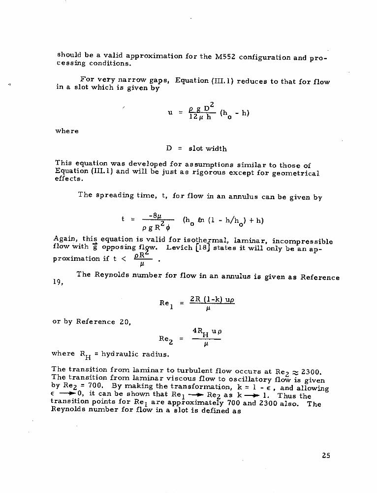
Lack of hydrostatic pressure and dominance of surface tensionwill allow dwell pool shape to be different (more spherical) and maycause shallower eb penetration. The different pool shape will occurbecause surface tension acts to pull the melt toward cooler surfaceswhich is away from the electron beam in this case. Assuming that thenet gravitational field is always aligned with the beam in Skylab proces-sing, the situations illustrated in Figure 4 will result regarding bulkmelt behavior of the dwell pool. As seen in Figure 4a surface ten-sion dominance will pull the melt away from the beam, resulting inless resistance and deeper beam penetration than in terrestrial proces-sing when heating from above. When heating from the side, however,terrestrial processing allows the melt to run out of the pool which willprobably lead to even less resistance and more penetration than inspace processing. Shallower dwell penetrations should be expectedaboard Skylab because ground samples were processed as in Figure4b.
As predicted, the gravity sag illustrated in Figure 4 was evi-dent in the ground samples shown in Figures 5a and 6 a which alsolead to more extensive dwell penetration than in the flight samples.No "sag" was evident in the aluminum and steel flight samples shownin Figures 5b and 6b as the dwell shape appeared similar to Figure4a.
F. SURFACE TENSION MEASUREMENTS
The surface tension of stainless steel was experimentallydetermined (Ref. 15). The resulting values for the estimatedliquid/vapor surface energy are given below.
Temperature Surface Energy Liquid Density(0 K) (10 -5 N/m) (gm/cc)
1868 1800 6.971943 1779 6.891993 1756 6.812058 1710 6.73
These values are adequate for engineering evaluation analysis. Theabsolute accuracy cannot be estimated, and no previous measurementshave been found for comparison. The important temperature coeffi-cient of variation of the surface energy for SS 304 alloy is rather large,-0.47 (x 10- 5 N/mK) (erg/cm2OC).
16

EB Microgravity
a. During Space Flight
EB
b. During Ground Testif Heating from the
Gravity Side
EB
Gravity
c. During Ground Test if Heating from Above
FIGURE 4. PROPOSED M551 DWELL POOL BEHAVIOR [17]
17
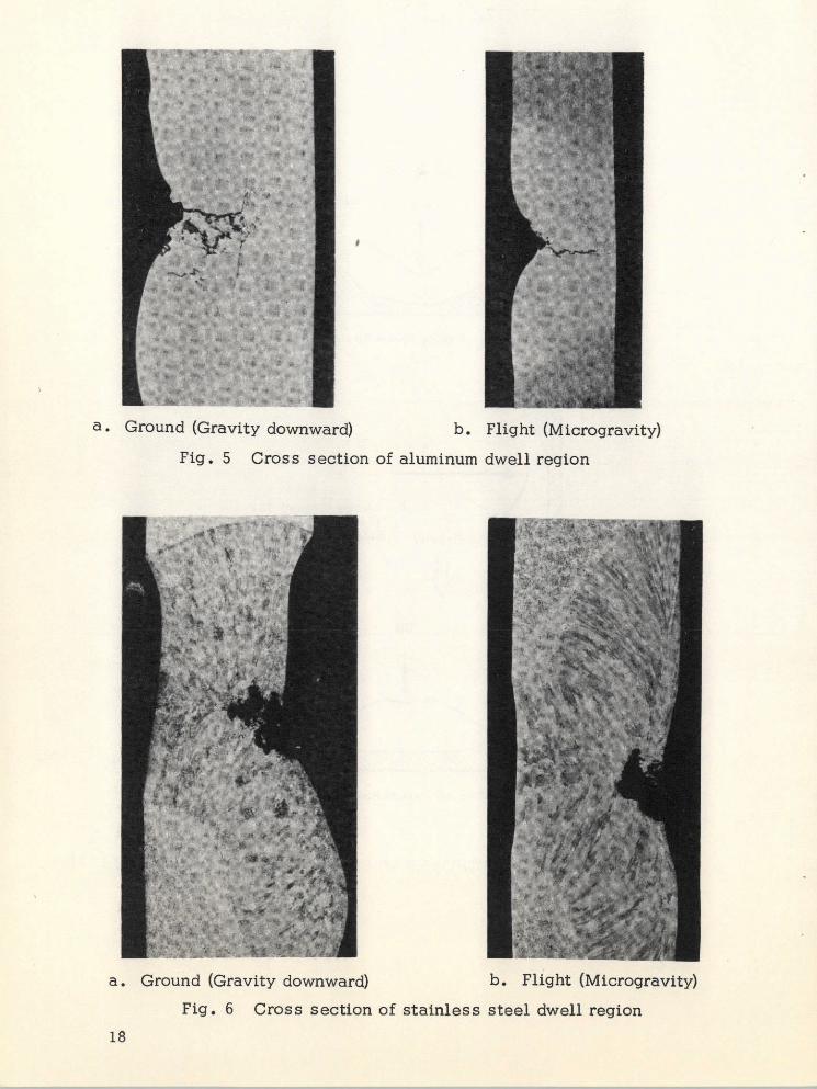
a. Ground (Gravity downward) b. Flight (Microgravity)
Fig. 5 Cross section of aluminum dwell region
a. Ground (Gravity downward) b. Flight (Microgravity)
Fig. 6 Cross section of stainless steel dwell region
18

G. CONCLUSIONS
The primary conclusion which can be reached from the resultsnow available is that no significant practical differences exist betweenterrestrial and microgravity electron beam melting. The differencesfound to date - oxide free front surface for the full penetration weld inthe aluminum flight samples and the lack of gravity sag and shallowerpenetration in the stainless steel flight sample dwell - do not seem tohave any practical benefits or detriments for conducting this operationin space. Although no results have been reported to date, the changein spiking frequency with gravity level and degree of melt superheatcould lead to an increase in porosity and cold shuts in low gravityelectron beam welding.
It is noted that the only other known low gravity electron beamwelding experiments ever conducted [16Jhave come to similar con-clusions using similar materials, beam parameters, chamber anddisks, movie coverage and low-g aircraft experimentation. Theirconclusions[16] were that not much difference existed between Earthand low-g specimens; aluminum rendered continuous beading, where-as stainless steel resulted in droplet beading; weld shape and penetra-tion were the same on Earth and in low-g; and more porosity existedin one oLfthe low-g specimens.
No qualitative evaluations could be made on the magnitude andpattern of flow in the dwells because filming speed was too low. Thiswas true for both ground and flight tests.
Surface tension and vaporization forces were dominant for thisexperiment both on the ground and in Skylab. Gravity forces werealso important in determining dwell shapes for stainless steel andaluminum ground tests.
19

SECTION If. M552 EXOTHERMIC BRAZING EXPERIMENT
This section contains descriptions of the physical forces and
their effect for the M552 experiment. The first portion of the chap-
ter addresses the capillary flow analysis, while the second segmentdiscusses bubble dynamics associated with M552. The next two sec-
tions discuss variable gap flow effects and pertinent surface tension
measurements, respectively. Finally discussions of flight results
are presented
The solid materials being brazed were tubular sections of 304L
stainless steel and pure nickel. The brazing alloy was a eutectic
composition mixture of silver and copper (72% silver, 28% copper)
containing a small concentration (0.5%) of lithium. There were four
specimen designs in which the most important variations were in the
composition of the solid (stainless or nickel) and dimensions of the
capillary gap between the inner tubular section and the concentric
outer sleeve. In all specimens the silver-copper braze alloy was pre-
placed in ring-grooves situated for that purpose, one at each end of
the specimen. Upon melting, flow of the liquid silver-copper alloy
into the gap was under the impulsion of capillary action, in which the
force producing flow is primarily surface tension. Gravity, when
present, has a modifying effect on the surface tension force field
which may or may not be negligible, depending on the magnitude of
the capillary gap. The four specimen designs are listed below:
0.005" - Gap - 304L MaterialSLS1 - Skylab Flight SpecimenMCS-1, 2 and 3 - Ground Characterization
Specimens
0.010" - Gap Pure NickelSLN2 - Skylab Flight SpecimenMCN-1, 2 and 3 - Ground Characterization
Specimens
0.020" - Gap 304L MaterialSLS3 - Skylab Flight SpecimenMCS-4, 5 and 6 - Ground Characterization
Specimens
0.000" - 0.030" Taper Gap - Pure Nickel MaterialSLN4 - Skylab SpecimenMCN-4, 5 and 6 - Ground Characterization
Specimens
20

A. CAPILLARY FLOW
The effect of gap width and low gravity on capillary flow in theM552 Exothermic Brazing Experiment has been studied. Time-to-spread, flow velocities and Reynolds number have been calculatedfor the configuration shown in Figure 7. The results are shownin Tables 4, 5 and 6.
The results indicate that [17]:
* Spreading time will be up to 50% shorter in gravityfields anticipated for Skylab than in ground tests.
* Turbulent or oscillatory laminar flow will occur inSkylab processing in certain gaps where only laminarflow could occur in ground tests.
The flow equation for an annulus is given by,
S 8p h (h - h) (III.1)
where
u = velocity
h = axial position in annulus
p = density
R = sleeve radius
A = viscosity
k = tube radius/sleeve radius
1-k 4 1-k 2= +
1 -k 2 Ink
g = gravity
h2 coso p g R (1- k)
a = surface tension
0 = contact angle
Equation (III.1) was developed assuming laminar, steady state, incom-pressible, isothermal flow with g opposing the flow direction. It
21

Tube
Mid-PlaneSteeve
7 Varies .34 -w
Gap Width .16"
Slot forBraze Ring
FIGURE 7. M552 CONFIGURATION
22

Table 4
M552 SPREADING TIMES
Gravity Gap Width Spread Time (Annulus)
(g/gE) (in.) ( sec)
2 106 .005 12.00.010 6.00.020 2.97.030 1.76
1 .005 13.60.010 7.47.02 0 4.42.030 3.60
Assuming no variation in gap width.
Table 5
M552 FLOW VELOCITIES
Geometry Gravity Gap Velocity (u)
(g/gE) (in.) (cm/sec)
Annulus 2 10 .005 34.010 67.020 134.030* 200
1 .005 30.010 55.020 90.030* 97
Slot 2. 106 .005 33.010 66.020 132.030* 198
1 .005 30.010 53.020* 81.030 84
Assuming no variation in gap width.
23

Table 6
M552 REYNOLDS NUMBERS
Geometry Gravity Gap Flow
(g/gE) (in.) Re1 Regime
Annulus 210 6 .005 202 Laminar.010 794 Oscillatory.020 3200 Turbulent.030 7210 Turbulent
1 .005 182 Laminar.010 650 Laminar.020 2170 Oscillatory.030* 3490 Turbulent
Slot Z.10- 6 .005 99 Laminar.010 395 Laminar.020 1580 Laminar.030 3550 Turbulent
S.005 90 Laminar.010 315 Laminar.020* 970 Laminar.030 1500 Laminar
Assuming no variation in gap width.
24
should be a valid approximation for the M552 configuration and pro-cessing conditions.
For very narrow gaps, Equation (III.1) reduces to that for flowin a slot which is given by
2U = 1p h (h - h)
where
D = slot width
This equation was developed for assumptions similar to those ofEquation (III.1) and will be just as rigorous except for geometricaleffects.
The spreading time, t, for flow in an annulus can be given by
t = p(h In (1 - h/h ) + h)pgR o
Again, this equation is valid for isothermal, laminar, incompressibleflow with g opposing fl w. Levich [18] states it will only be an ap-proximation if t < .
The Reynolds number for flow in an annulus is given as Reference19,
Re = 2R (1-k) up1
or by Reference 20,4 RH up
Re 2 =
where RH = hydraulic radius.
The transition from laminar to turbulent flow occurs at Re 2 ~2300.The transition from laminar viscous flow to oscillatory flow is givenby Re 2 = 700. By making the transformation, k = 1 - E, and allowingE -p-0, it can be shown that Re 1 -- Re 2 as k 1. Thus thetransition points for Re 1 are approximately 700 and 2300 also. TheReynolds number for flow in a slot is defined as
25

Re =u
s
and the laminar-turbulent transition is at Re s - 2000.
B. BUBBLE DYNAMICS
Many ground and KC-135 aircraft tests for M552 have exhibiteda bubble or void space within the braze structure. Analysis of themovement of such a bubble in low gravity and the nonisothermal con-ditions of M552 has been completed. These analyses are applicable tomotion of gas bubbles only and will not predict the location of shrink-age voids.
Neglecting wall effects, the limiting velocity of a single bubblemoving in a homogeneous liquid under the combined influence of agravity field and a temperature gradient is given by Reference 21,
2 3 aA da dT 2 +J)u - 3 gB 3 tgA dT dz ( g - P) ga (Ig+P)
where
A = 2 + k I/k
B = 3 p + 2
k = thermal conductivity
IA = viscosity
a = bubble radius
a = surface tension
T = temperature
p = density
g = gravity
and subscripts I and g refer to the liquid and gas phases, respectively.The temperature gradient affects bubble motion through tangentialstresses at the bubble-liquid interface. These stresses are caused bysurface tension gradients across the bubble. The surface tensionmechanism is termed the Marangoni effect, which can be caused byeither temperature or concentration gradients.
26

The ratio of buoyant/Marangoni forces on the bubble is given
by,
(p - pg) ga (Ig + ) A
3 du dT3 4g dT dz
where y = buoyancy/surface tension forces. Values of y for various
size bubbles and gravity levels are given below for M552 conditions
using a 100C/cm temperature gradient,
BubbleDiameter Gravity y
(cm) (g/gE)
10-4 1 106
10 - 4 10 - 6 1
10 - 2 1 10 5
10-2 10-6 10- 1
Thus, Marangoni forces will be important in Skylab, but not on ground
tests.
C. CAPILLARY PUMPING IN TAPERED GAPS
Upon melting the braze alloy in the M552 tapered gap specimens
(SLN-4, MCN-4, MCN-5 and MCN-6) will have the configuration shown
in Figure 8. Ignoring gravity effects and contact angle hysteresis
[22 and 23], the pressure gradients determining flow direction are
determined solely by simple capillary effects, as follows [24, 25
and 26]:
2cr cosOP-P1I R1
2c coseP " P2 RR2
where the contact angle e, the pressures P, P 1 and P 2 and the radii
of curvature R 1 and R are shown in Figure 8. The term a is
the surface tension of the liquid vapor interface.
27

R Molten 2 P/ Braze
/0 Alloy er/'Z_
Tube
Flow Direction(assuming 0 < 0 <-)
FIGURE 8. TAPERED GAP CAPILLARY PUMPINGFOR THE M552 EXPERIMENT
28

By eliminating the common term P from these equations, thefollowing results
P 1 P 2 = 2c cos0 > 0
because R 1 is greater than R2 . Thus the molten braze will alwaysflow toward the narrow end of the tube.
The same would be true when gravity is considered becauseground tests were conducted vertically and g-levels aboard SkylabII were less than 10-4 gE; i.e., the ratio of hydrostatic to capillarypressures are:
P gh -32 cos 1 <3x 1 0 3
RR
2a cose (R 2 R1
Like gravity effects, contact angle hysteresis (advancing and recedingangles differ) should also have negligible effects on final melt position,because hysteresis will only affect the rate of flow and not the flowdirection.
D. SURFACE TENSION MEASUREMENTS
The values of surface tension, a, for both the Ag/Cu eutecticbraze alloy BT720, and the same alloy with nominally 0.2% lithiumaddition, Lithobraze BT720, were measured as [15]:
Temperature Surface Tension
Braze BT720 11730K 996 x 10-5 N/cm*1273 9651373 9561473 917
Lithobraze BT720 1273 9671413 9421473 930
"Multiply by 105 to get dynes/cm or ergs/cm2
The surface energies of the two Ag/Cu braze alloys are plottedas a function of temperature in Figure 9. With an error of 1% ina and 20 0 K in T, a least mean square line gives a slope of S 2 d ca/dT- -0.25 x 10⁻⁵ N/cmoK (-0.25 ergs/cmZoC). This can be comparedwith a value of S = -0.31 x 10⁻⁵ N/cmoK for pure copper.
29

Curve 653747-A
1010 I
1000 0 Ag +28 Cu
990 - o Ag +28 Cu +0.2 Li
980 -
970 -
z 900 E
o 950
94 1%error in a940 - 200 error in T
930 -
920 - doidT= -0.25 erg/cm2 deg K
910 -
900
I I I II
1070 1170 1270 1370 1470 1570Temperature o K
Fig. 9 -Surface energy vs temperature Ag-Cu solderalloys. Al203 substrate, argon atmosphere. [is5]
30

E. FLIGHT RESULTS
Radioisotope tracer mapping of Skylab samples SLN-2 andSLN-4 showed very interesting differences and similarities whencompared with similar maps of ground-test samples. One significantdifference was the enhanced braze alloy flow (with subsequent in-creased movement of tracer alloy) observed in the samples brazed in
space under near-zero gravity conditions. Radioactivity was observedfor both samples SLN-2 and SLN-4 well outside of the ferrule regionon the double-scribed or tracer pellet end. With gravitational forcesabsent, capillarity of surface forces were unopposed, resulting inrather dramatic increased flow of the braze alloy. Another differencedue to the absence of gravity was manifested in sample SLN-4, a taperannulus sample, which demonstrated the absence of a braze "leveling"effect noted on ground-test samples; islands of braze alloy filled re-gions having very large gap widths. In some respects, the radiationintensity maps for the Skylab samples SLN-2 and SLN-4 were verysimilar to those obtained from earth samples. The tracer alloy movedinitially toward the thermally hot regions near the igniters. The l"oAgtracer maps for all of NASA M-552 braze assemblies suggest that suchtracing can provide a picture of the thermal history for any particularassembly as well as accurate braze alloy flow information. Since noother analytical technique would provide this unique composite viewof surface, gravitational, and thermal forces, radioisotope tracingproved useful in interpreting other metallurgical aspects of this ex-periment [27].
An observation of major importance is that true capillary flowcan be developed in wide-gap apertures when gravity is absent. Thishad been predicted, and was a reason for inclusion of wide-gap speci-mens (SLS-3, 0.020 inch gap and SLN-4, tapering to 0.030 inch gap).
There are practical as well as scientific implications to wide-gap capillary behavior. One principal consequence is that brazing, asa means for joining materials, is a much more versatile process inzero gravity space environment than it is on earth. Commercial ter-restrial capillary brazing is limited by gravity interference to gapclearances rarely exceeding 0.005 inch, which imposes serious con-straints on machining and fixturing. The absence of the need forclose clearances and relatively smooth parallel surfaces, as requiredon earth, greatly extends the applicability of brazing as contrasted,for example, with welding, fastening, or other joining techniques,when structural fabrication is to be done in space environment.
Some general characteristics of capillary flow were manifestedin a review of metal distribution in all M552 Skylab specimens. Thepressure in liquid near a small gap meniscus is smaller than near awide gap meniscus; therefore pressure differences develop in complex
31

capillary systems tending to drive the liquid from wide gap to narrowgap locations. For example, when the braze gap was fairly narrow(SLS-1, 0.005 inch), the ring-grooves were almost drained of liquid;in a wide gap specimen (SLS-3, 0.020 inch), not only was the joint"starved" as mentioned above, but the wide gap was far less effec-tive in draining liquid from the ring-grooves (thus contributing in-directly to the "starvation" of the joint). In consequence, anobservable, measurable meniscus developed in ring-grooves nearwide gaps. For example, the upper ring-groove in specimen SLN-4is near a very wide (0.030 inch) gap, which was incapable of with-drawing much liquid from the groove and the residual liquid formeda meniscus according opportunity for observation of a radially sym-metrical liquid-vapor surface contour in the absence of gravity. Thiscontour has been found numerically consistent with the following equa-tion which governs in the absence of gravity, provided the surface ten-sion is uniform from point to point on the meniscus surface [28].
dY G ( 2y )2= -1y 2+C
where
Y = distance from the centerline of the specimento a point on the meniscus, measured perpen-dicular to the centerline
X = distance measured parallel to the centerlinefrom the center of the ring-groove
C = integration constant
a = surface tension
AP = pressure difference prevailing across themeniscus surface (and constant from point topoint along the meniscus surface)
The conformance of the meniscus surface with the equation sup-ports the conclusion that the liquid-vapor surface tension is substan-tially uniform. This is of importance because the surface tension isquite sensitive to variations in temperature and surface composition.
F. CONCLUSIONS
The absence of gravity greatly extends the scope of brazing, and,thereby, the applicability of brazing to fabrication in space. In zero
32

gravity environment, the surface tension forces begetting capillaryflow are unfettered, while on earth these forces must compete with
gravity. Study of braze alloy distribution in Skylab specimens clearly
indicates that dimensional tolerances, especially braze gap clearances,
will be far less critical to joining operations in space than on earth.
The practical significance of this fact, which had been predicted but
never tested, can hardly be overemphasized. In space fabrication,
many joints, which on earth would be produced by welding, should
probably be brazed.
Liquid-vapor boundary surfaces (menisci), and the flow of liquid
metal under the impulsion of surface tension forces, are in close con-
formance with what had been predicted for zero gravity environment.
There were no unexplained effects, and, in the Skylab specimens, the
surface tension of liquid silver-copper alloy appears to have been
quite uniform.
33

SECTION I1. M553 SPHERE FORMING EXPERIMENT
This chapter contains analyses of the physical forces for the M553experiment. The first section contains analyses of the driving forces,magnitude and pattern of natural convective fluid flows which occur inthe Sphere Forming Experiment. Following sections address tra-jectories of released samples, shape dynamics, surface tensionmeasurements, shrinkage pressure in freezing spheres and flightresults.
A. CONVECTION ANALYSIS
As in the other M512 experiments, the physical forces andattendant fluid dynamics of the M553 experiment are important factorsin determining the quality of the final product. Flow patterns in themolten material are important because all of the sample materials havelow entropies of fusion [1]. Thus, their solidification (microstruc-ture) is controlled by the rate of heat transfer removal [2] , whichchanges with the fluid flow [3 and 4] . The degree of flow will alsodetermine the amount of mixing attained. If no or little flow werepresent, all heavier components would segregate to the lower portionof the spheres on earth, but to a negligible extent in the microgravityenvironment of space. Fluid flow can also affect the shape and re-lease of the specimen while it is retained on the ceramic holder.
Application of dimensional analysis [5 and 6] to the governingequations for eb melting, coupled with ground-based and KC-135 ex-periments, should enable prediction of the extent of reduction or in-crease of motion in the molten metal and/or the change in flow patternin electron beam melting in space. Possible physical forces which couldinduce fluid flow in the M553 experiment, and their causes, include:
* Effective Gravity Force: Resultant force on weldspecimen due to earth's gravity and centrifugal andcoriolis forces of orbiting spacecraft.
* Lorentz Force: Electromagnetic forces induced bypassage of the electron beam current through thespecimen.
* Electrostriction: Stresses induced when electricalpermittivity changes with density.
34

e Magnetostriction: Stresses induced when permeabilitychanges with density
* Electrostatic Force: Caused by presence of excesselectrical charge (due to beam current and/or therm-ionic emission).
* Surface Tension: Tangential stresses at vapor-liquidinterfaces can be induced if surface tension dependson temperature and/or concentration. Surface tensionwill also cause pressure gradients across curvedinterfaces.
* Density Differences Accompanying Phase Changes
* Beam Force: Impinging electrons giving up theirmomentum.
* Thermal Expansion: Dilation and compression offluids whose density changes appreciably withtemperature can induce fluid flow.
* Vibration: Uncontrolled movement due to engine
operation, astronaut motion, particle impacts, etc.
* Centrifugal and Coriolis: Generated by disk rotation.
* Vapor Pressure: Evaporating molecules impartmomentum which leads to normal stresses at vapor-liquid interface.
* Inertia Forces: Tend to sustain induced motions.
* Viscous Forces: Tend to resist driving forces.
Governing Equations
The preceding forces, which could influence fluid flow andsolidification, appear explicitly in the following conservation equa-tions which apply to formation of a molten pool by electron beamheating.
Continuity (Mass Balance):
+ V (pV) = 0
35

where
p = density
V = velocity vector
t = time
V = "grad" or "del" operator
Momentum:
p + p(V. V) V = -VP + A V V + p g
Inertia Viscous GravityForce Force Force
+JxB +pe E
Lorentz and Electro- Electrostaticmagnetostriction ForceForces
whe re
P = pressure
S= viscosity
g = gravity vector
J = electrical current density
B = magnetic flux density
Pe = excess charge density
E = electric field density
36

Energy:
P S 8T - 2pCV8t + PCv (V ' V) T = k V T + 4 + pQ
2--+ Jc/, - ( T/K) V V
Thermal Expansion
Source
where
T = temperature
CV = heat capacity
k = thermal conductivity
= viscous dissipation function
Q = internal heat sources
Jc = "conduction" current = a(E + Vx B)
a' = electrical conductivity
I ( I T )
p aT p
K = ( @)P P T
Maxwell's Equations:
VXE -B/at
VXH = J + t
V B=0
V D pe
whe re
D = displacement current
H = magnetic flux
37

Constitutive Relations:
D =E'E
B = H
J = o'(E+VxB)+p V
p = Poll- pAT +KAP]
where
E ' = permittivity (dielectric constant)
' = permeability
Vapor-Liquid Boundary Conditions:
Force Balance,
p(2) (1) + + + I
1 1 2
Beam and Vapor Surface Tension ForcesPressure Forces
( v(2) v(2) (1) ()A(2) + k - (1) + k n
= k + - ( vk a+ nkI ak I k
whee (1l 2) (1, 2) (1, 2) (1, 2)where P (1,), (12 , vi(, 2) Vk ) are, respectively, the pres-sures, viscosities, and velocity components in Phases 1 and 2, a isthe surface tension, R 1 and R 2 are the principal radii of curvature ofthe surface, ni(i=l, 2, 3) are the components of the unit vector normalto the surface and directed into the interior of Phase 1, and summa-tion over a repeated index (k=l, 2, 3)is assumed. (See [14] for details.
Energy Balance,
4 4(T s -T )-kn VTs =QEB
38

where
E = emissivity
a = Boltzmann's constant
T s = surface temperature
T = environment temperature0
n = outward unit normal vector to free surface
QEB = heat flux from electron beam
Continuity of Velocity,
nx (V ) = 0
T1) 7,%2)n V = n*V = 0
Solid-Liquid Boundary Conditions:
Along stationary interfaces the no-slip condition (all componentsof velocity vanish) holds; whereas at moving interfaces (along meltingor freezing fronts), a one-dimensional material balance yields
u i = (1 - ps/PL) d6/dt
where
u i = fluid velocity normal to the interface
6 = position of the interface relative to theorigin of the spatial coordinate system
ps = solid density
PL = liquid density
This is the source of the density-difference-accompnahing-phase-change force for fluid flow. Also for a melting interface, an energybalance yields:
ST T d6LTL S s dt
39

whe re
T L = liquid temperature at the interface
T S = solid temperature at the interface
A = heat of fusion
and
T - TTS M
The preceding equations are based on the following assumptions:
* No influence of external fields on physical properties
* No coupling between constitutive flux relations (e.g.,no Soret effect)
* Single-component, Newtonian fluid
* Constant physical properties
* Bulk coefficient of viscosity vanishes.
They are written in general vector form wherever possible, since they
also apply directly to M551. It should be noted that only the differences
in physical properties and geometry will differ in a dimensional analy-sis of M551 versus M553.
Dimensional Analysis
The controlling physical forces can be determined by nondimen-
sioning each of the preceding equations and performing an order-of-
magnitude comparison on the various dimensionless groups which
result [5 and 6J. The key to successful analysis is in choosingthe proper reference values; i.e., since no freestream velocity exists,
which forces do we equate to estimate a "characteristic" or "typical"
velocity. Choosing the proper characteristic velocity is very im-
portant, since the reference time, temperature, etc. usually depend
on this velocity.
Previous examinations of film showing both KC-135 flight ex-
periments and ground tests for the M553 experiment indicated fluid
velocities exceeded 300 cm/sec (p. B-5 of Reference 29). Continued
M553 film analysis has since shown that flow velocities for nickel
40

specimens on both KC-135 and ground tests have been approximately20 cm/sec. Of the 14 possible forces affecting electron beam melting[30], only those shown in Table 7 yield characteristic velocitiesof this order of magnitude. These driving forces consist of couplingsinvolving surface tension, gravity or Lorentz (electromagnetic) forceswith inertia forces. Previous studies based on faster velocities hadindicated coupling with viscous, rather than inertia, forces as con-trolling [29]. This indicates the importance of choosing the correctcharacteristic velocity. Preliminary analysis also suggests thatmagnetostriction forces may also be important, but gross uncertaintyin electromagnetic property data for liquid metals precludes any de-cision at the present time.
Table 7
PROBABLE CHARACTERISTIC VELOCITIESIN ELECTRON BEAM MELTING
Velocity
Controlling Functional Form Value (cm/sec)Forces for Nickel in M553
Inertia = Surface (ST/pL)1/2 20Tens ion
Inertia = Lorentz (ao' E 2 L/p) /31
Inertia = Gravity (gL)1/2 18 at I E
6 at 10-4 E
Viscous = Lorentz (a' E 2 L2/1)I /2 7
The dimensionless momentum equation which determines fluidflow in electron beam melting becomes (upon choosing the surfacetension-inertia characteristic velocity),
41

av + 1 -- -- 1 VP + V 2V
N p Nh p (V * V) V = 2NOh
NNMI (V --+ - (pg) + (Vx B) x B (IV.l)NOh NOh
where
NSt = Stokes number = pt /pL
= duration of process/residence time
NOh = Ohnesorge number = p / Po LST o
= viscous force/surface tension force
NBo = Bond number = p 0 g 0 L 2 /ST 0
= gravity force/surface tension 2B2 Lo
NMI = Magnetic interaction number = Z ST
= magnetic force/surface tension
Using physical property data for nickel and beam parametersfor the M553 experiment, the equation reduces to
10 3 p . + 03 p (V. V)V = - 103 VP+ V 2
+ G(pg) + 01 (Vx B)xB
whe re
G = 103 for earth gravity
G = 10 - 1 for expected Skylab gravity.
This order-of-magnitude analysis indicates that surface tension driven
convection will occur both in ground tests and for Skylab conditions be-
cause NOh << 1. This is confirmed by KC-135 M553 tests. Further-
more, gravity driven convection will exist on ground tests, but will be
negligible in the reduced gravity of Skylab. Thus different forces will
42

control convection on earth versus Skylab. The preceding analysisalso indicates that electromagnetic or Lorentz forces will be negligiblewith regard to causing fluid motion.
The surfake tension driving force considered above is actually asurface tension gradient caused by radial and lateral temperaturegradients. Ignoring convection, gradients of at least several hundreddegrees Celsius per centimeter have been predicted during melting[31]. It can be shown by dimensional analysis (equate inertial andviscous terms) that the motion caused by the initial temperaturegradients will occur in less than 0.1 second and can persist for 60seconds after removing the driving force. This means that there willbe some fluid motion during solidification if the M553 specimens freezeafter 30 to 40 seconds as predicted.
Values of the pertinent dimensionless groups for the remainingM553 materials are given in Table 8. As can be seen, no significantchanges are evident from the preceding conclusions for pure nickel.
Table 8
M553 DIMENSIONAL ANALYSIS
NN t1 NBo NBoMaterial NOh NBo NOh NOh NOh
Ni-Sn 4.4 x 10 - 4 1.50 2292 3437 .34
Ni-Ag 5.0 x 10 - 4 1.53 1991 3043 .30
Ni-Cu 4.45 x 10⁴ 1.54 2107 3241 .32
With Earth gravity (9.8 m/sec2 )
tWith 10 - 4 Earth gravity
It should also be mentioned that the effects on fluid motion of sur-face free charges (excess electrostatic charge) and related electric andmagnetic forces at the drop surfaces have been examined. The resultsof the examination indicate that these surface charges are negligibledriving'forces for fluid motion. These results were also reviewed by
43

Professor J. R. Melcher of MIT's Electrical Engineering Department,and he was in full agreement with these results'". Furthermore,from the manner in which patches of surface contaminants movedabout in the ground films, it is apparent that surface tension drivenflows due to concentration gradients are also important in this ex-periment. No reliable data exist, however, on what these impuritiesare, nor what the value of surface tension gradient with compositionis. Thus the Marangoni effects are limited to thermal differencesonly in this study.
B. M553 TRAJECTORY ANALYSIS
One of the most important aspects of the M553 experiment is themotion of the sphere after deployment since this determines what free-float time will exist. In order to predict the motion, a trajectory pro-gram has been developed that includes allowances for:
* Electron beam force
• Deployment velocity (spring)
* Vaporization force based on 3-D temperaturehistory
* Skylab orbit considerations
* M512 position considerations, and
* Allowances for additional forces as independentsubroutines (KC-135 g-level data).
In general a solution to the equation of motion
dt
is obtained numerically via Simpson's rule subject to the followingboundary conditions:
=dR ---
R = 0 and d V att =Odt o
Integration of the equation of motion twice yields
t r
R = tV 0 + f ()d d
0 0
Private Communication, Huntsville, Ala., 11 June 1973.
44

which produces the desired trajectory in chamber coordinates centeredon the specimen. This computed trajectory is then transformed tocamera coordinates to show the path as seen in the film, i.e.,
(t) = [A] S (t)
where R (t) is the projected trajectory and[A] is the transformationmatrix obtained from the hardware. For camera 1
.932 -. 363 0A = -. 203 -. 521 -. 829
.301 .773 -. 560
and for camera 2
.661 -. 183 -. 728A = -.224 -.974 .041
-. 716 .136 .685
The eb force was discussed in Reference 31 and Table 9 givesthe magnitude of this force for two eb currents. To establish themotion as a result of the eb force, the conversion efficiency and ebcutoff time must be known. This time corresponds to the time delayassociated with automatic shutdown of the eb due to sting melting.Original estimates were from 10 to 20 milliseconds; however, highspeed movies (1000 frame/sec) taken during the M553 ground-basedtest at MSFC on 20 October 1972 show conclusively that longer timesexist. During their test the spring loads were varied on the shutdownmechanism to experimentally establish the time interval the eb is onafter melting occurs. It was found that for a 150-g spring load a cut-off time of 410 milliseconds was measured while 220 milliseconds wereobserved for a 200-g load. This cutoff time translates into a free-float time of approximately 12 seconds for a 150-g load and 23 secondsfor the 2 0 0 -g load. Thus the expected free-float time is drasticallyreduced from the 250 seconds corresponding to the original 20 milli-seconds estimate.
An analysis was performed to determine if the cohesive energy-generated kinetic energy is sufficient to cause deployment in theabsence of external forces. This was done to allow initial conditionsto be calculated. To reduce the complexity of the problem, the fol-lowing assumptions were made:
45

Table 9.
TOTAL FORCE DUE TO ELECTRON BEAM
2m V
F =I ee e
m F FI e e V e e(amp) (coulomb) (kg) (V) (N) (dyne)
0.05 1.6 (10) - 19 0.9(10) - 3 0 2(10) 4 2.38 (10) - 5 2.38
0. 10 1.6(10)- 1 9 0.9(10) - 30 2(10)4 4.76 (10)- 5 4.76
* Zero gravity field
" No sting melting
* Sting pulled down before breaking
* Perfectly spherical free surface, and
* Contact angle of 120 degrees.
An energy balance was made between the initial and final statesand from this the kinetic energy is found as
KE = LV (ALV(i) ALV(f) +
LS LS ) -ALS )
This kinetic energy was calculated as a function of penetration(H) of liquid into orifice. The value of H simulates the effect of thespring in pulling the liquid down via adhesion between liquid and solidsting. The results of this calculation are
46

Penetration, H Kinetic Energy(cm) (ergs)
0.0 0.0
0.1 62.7
0.5 293.0
1.0 597.0
The value of the kinetic energy must then be greater than thework of adhesion (or energy of adhesion) for deployment to occur. Thework of adhesion was found to be 265 ergs; thus for depressions of morethan 0.5 cm deployment will occur due to cohesive effects alone. Thesecriteria are included in the trajectory computer program to allow initialconditions for the numerical integration to be determined.
Tables 10 and 11 show the surface temperature distribution at3.0 and 3.5 seconds, respectively, for Ni and Ni-12% Sn. These datawere used in conjunction with the Langmuir theory discussed inReference 31 to calculate the net vaporization force as a function oftime. A sample calculation is presented in Table 12 for both Ni andNi-12% SN for the first second after eb cutoff. It is seen that between3.5 and 4.25 seconds the vaporization force is of the same order ofmagnitude as the eb momentum force. During the first half secondthe calculations yield a large vaporization force (comparable to surfacetension forces) and represent an intolerable situation as far as the free-float time is concerned. However, due to the large temperature gra-dients existing, the resulting surface tension driven convection willtend to reduce these values.
The Skylab orbit effects are included in the analysis by the methodof Parker and Gatewood [32]. The computer program presented inReference 31 was used as a subroutine in the present analysis to couplethe effects of M512 position and orbit to the physical phenomena occur-ring in the vacuum chamber.
C. CONCLUSIONS BASED ON TRAJECTORY COMPUTATIONS
It has been shown that free-float times from 32 to 48 seconds(depending on the material) are required for complete containerlesssolidification to occur. The magnitude of each of the physical forceswas discussed and general comments made concerning the effect ofeach on free-float time in the previous section. This subsection sum-marizes some of these conclusions.
47
TABLE 10
TEMPERATURE DISTRIBUTION AT 3.0 SECONDS
Nickel Nickel - 12% Tin
Node Temp. Vapor Pressure Temp. Vapor PressureNo. . (0C) (mm Hg/cm 2 ) (Oc) (mm Hg/cm 2 )
36 2036 .3959 2013 .700137 1463 .0006 1537 .006938 Z193 .464 2157 .696539 1900 .0395 1903 .096240 1728 .0067 1757 .025341 1677 .0037 1716 .0168
42 1677 .0037 1716 .016843 1728 .0067 1757 .025444 1900 .0400 1903 .096345 2193 .4644 2157 .696546 1801 .0202 1815 .060247 1695 .0063 1731 .0266
48 1609 .0022 1663 .013249 1573 .0014 1634 .009650 1573 .0014 1634 .009651 1609 .0022 1663 .013252 1695 .0063 1731 .026653 1801 .0201 1815 .0602
54 1633 .0030 1680 .015955 1584 .0016 1642 .010556 1537 .0009 1605 .006957 1513 .0006 1586 .005658 1513 .0006 1586 .005659 1537 .0009 1605 .0069
60 1584 .0016 1642 .010561 1633 .0020 1680 .015862 1535 .0006 1602 .004963 1515 .0005 1585 .004164 1492 .0003 1567 .0033
65 1480 .0003 1557 .003066 1480 .0003 1557 .003067 1492 .0003 1567 .003368 1515 .0005 1585 .004169 1535 .0006 1602 .0049
48

TABLE 11
TEMPERATURE DISTRIBUTION AT 3.5 SECONDS
Nickel Nickel - 12% Tin
Node Temp. Vapor Pressure Temp. Vapor PressureNo. (OC) (mm Hg/cm 2 ) (OC) (mm Hg/cm 2 )
36 1689 .01249 1678 .033237 1601 .00429 1624 .018538 1685 .0041 1676 .011139 1679 .0038 1674 .010940 1672 .0035 1671 .0105
41 1667 .0033 1670 .010342 1667 .0033 1670 .010343 1672 .0035 1671 .010544 1679 .0038 1674 .010945 1685 .0041 1676 .0111
46 1675 .0050 1672 .014447 1668 .0046 1669 .014048 1658 .0041 1665 .013549 1652 .0038 1662 .013150 1652 .0038 1662 .0131
51 1658 .0041 1665 .013552 1668 .0046 1669 .014053 1675 .0050 1672 .014454 1657 .0040 1663 .013155 1651 .0037 1660 .0128
56 1642 .0033 1657 .012357 1636 .0031 1654 .020058 1636 .0031 1654 .020059 1642 .0033 1657 .012360 1651 .0037 1660 .0128
61 1657 .0040 1663 .013162 1634 .0022 1649 .008363 1630 .0021 1648 .008264 1624 .0020 1645 .008065 1621 .0019 1644 .0078
66 1621 .0019 1644 .007867 1624 .0020 1645 .008068 1630 .0021 1648 .008269 1634 .0022 1649 .0083
49

Table 12SUMMARY OF VAPORIZATION FORCE CALCULATION
Nickel
Vaporization Time (sec)Force
(dynes) 3.00 3.25 3.50 3.75 4.00 4.25
f 882 55 8 1.5 0.3 .07x
f 1480 126 25 5.8 1.3 .3y
fz 292 25 5 1.0 0.25 .06z
Nickel-12% Tin
f 1400 102 9 1 0.16 .02x
f 2470 240 41 6 1.0 .16Y
f 485 47 8 1 0.2 .03z
* Electron beam force for a 4 6 0-g spring load has a dura-tion of approximately 100 milliseconds and gives rise toa float time of 40 seconds.
* Kinetic energy of sphere due to spring effects (deploy-ment technique) gives rise to float times of greaterthan 50 seconds.
50
e Vaporization force produces float times that are probablythe critical link in process. Best estimates of the cor-responding float time between 1/4 second after eb cutoffand occurrence of an isothermal outer layer range from5 to 20 seconds. For some cases the time could even beconsiderably less than 5 seconds.
* Skylab orbit effects give rise to 29 to 46 seconds offloat time.
* Superposition of all of these forces produces an additive(as opposed to canceling) effect in most cases. Trajectorycalculations show that even with conservative vaporizationforces float times of less than 15 seconds will occur.
Lockheed documented in December 1972 [33] an early projec-tion of anticipated float times less than the required containerlesssolidification times and again in April via the Science & EngineeringInformation Technical Note [34]. In the latter report a conservativeestimate of less than 20 seconds was forecast.
Another potential problem area, discussed in the 27 March 1973presentation at MSFC, is that even with the relatively large forces onthe sphere during the critical time of deployment, the possibility of"sticking" exists. Films of the KC-135 flight test showed that anadherence to the ceramic occurs on occasion that finally results indeployment due to acceleration transients in the ballistics trajectoryof the aircraft. A typical sequence is shown in Figure 10. The eventsare referenced to the time corresponding to what appeared to be thefully molten condition, t=0. For the ensuing 0.300-second, that adher-ence to the ceramic occurred with periodic motion due to the accelera-tion transients is evident in the film sequence. At 0.310-second,deployment occurred with the trajectory shown in Figure 10. Theimportant point remains, however, that without the accelerationtransients (relatively large compared to the Skylab gravitational en-vironment) specimen retention could have occurred. This adhesion isprobably due to contamination of the ceramic from previous melts.The conclusion is that the possibility of unintentional retained speci-men may occur in the actual Skylab mission.
D. SHAPE DYNAMICS
This subsection presents a summary of calculations made forNi and Ni-12% SN based on the thoughts outlined in Reference 31.First, the formation times are shown in Table 13 where it is seenthat the transformation to minimum energy occurs very rapidly. How-ever, due to inertial considerations, the spherical free surface is
51

t = 0 (sec) t = .250 (sec)
t = .275 (sec) t = .290 (sec)
t = .295 (sec) t = .310 (sec)
FIGURE 10. TRAJECTORY SEQUENCE - MARCH 1972 KC-135 FLIGHT(NICKEL) (CONTINUED)
52

t = .325 (sec) t = .360 (sec)
t = .395 (sec) t = .400 (sec)
t = .450 (sec) t = .515 (sec)
FIGURE 10. TRAJECTORY SEQUENCE (CONCLUDED)
53

"overshot" and oscillations are set up which continue until dissipatedby viscous damping. Table 15 gives the oscillation frequencies whileTable 14 shows the time required for viscous effects to dampen aninitial perturbation to 0.01% and 1% of its initial value.
Table 13
FORMATION TIMES FOR M553 MATERIALS
M553 Materials p u R T
(g/cm3 ) (dyne/cm) (cm) (sec)
Ni 7.85 2050 .3175 .011
Ni-12% Sn 7.80 1500 .3175 .013
Table 14
FREQUENCY FOR M553 MATERIALS
Material Frequency(Hz)
Ni 41
Ni-12% SN 35
Table 15
DECAY TIME FOR M553 MATERIALS
Material P p R Time Time Time
(g/cm-sec) (g/cm3 ) (cm) (constant) (.01%) (1%)
Ni .05 7.85 .3175 3.14 28.8 14.5
Ni-12% Sn .043 7.80 .3175 3.62 33.0 16.7
54

E. SURFACE TENSION MEASUREMENTS
The values of cLV, 0, and W determined from sessile dropexperiments [15] are given in Table 46.
Table 16
WORK OF ADHESION (WA) FOR NICKEL AND ITS ALLOYSON A1 2 0 3 (x 10- 5 N/cm)
Temp. (OK) aLV 0 (deg) WA
Nickel 1773 1719 135 5031973 1676 137 4502068 1659 (113) (1011)
Ni-l% Silver 1793 1637 135 4791983 1586 136 4452138 1564 128 601
Ni-12% Tin 1683 855 130 3051983 806 133 2562093 782 130 279
Ni-30% Copper 1743 1506 126 6212003 1468 130 5242073 1411 133 449
F. SHRINKAGE FORCES
When spherical melts solidify, the innermost melt is the lastto freeze. The advancing outer solid shell leads to hydrostatic ten-sions, even negative pressures, in the residual liquid and the generalplastic collapse of the spherical casting. The contraction (about 3%for most metals) is caused by solidification shrinkage. Several recentanalyses have been performed for this configuration [35 through37], and two extreme cases which could exist are shown in Figures11 and 12. In Figure 11 the residual liquid is considered to haveundergone cavitation. The homogeneous fracture pressure of mostliquid metals is thought to be on the order of -10- atm; however,heterogeneous nucleation may be possible at less negative pressures.
The tensile pressures within the residual liquid can be calcu-lated assuming various growth rates and outer shell deformation modes:elastic-plastic, Bingham, viscous or creep flow. Using the creepflow model, negative pressures in the liquid core of 1 cm radius nickelsphere are shown in Figure 13 using initial pressure of 1 atm. Nickel
55

FIGURE 11. UNSTRAINED OUTER CASTING ANDHOMOGENEOUS NUCLEATION OFRESIDUAL LIQUID UNDER EXTREMENEGATIVE PRESSURES [35]
Elastic Zone
f/
Plastic Zone
/Liquid c
! /
FIGURE 12. STATE OF A SOLIDIFYING SPHERICALCASTING WITH EXTERIOR SHELLDEFORMATION [35]
56

O I //S II I/
-o01
I..a 3
o ..11ff
, .. 'I."gY5i -so
C .-. OF LIQUID
-IO .. A - -3 - 'o -o o o 1 ,
RADIUS OF LIQUID CORE (CM)
FIGURE 13. HYDROSTATIC TENSIONS IN THE LIQUID CORE
OF 1 cm RADIUS CASTINGS OF ALUMINUM,COPPER, NICKEL, AND IRON CALCULATED
FROM THE CREEP MODEL [36]
spheres in the M553 experiment are 0.32 cm in radius. The tensile
pressures will be lesser in wide freezing range alloys [37].
Thus the value of possible shrinkage pressure developed within
spherical solidifying castings has been evaluated for various materials
exhibiting various deformation characteristics. The maximum at-
tainable stresses in aluminum, copper, nickel and iron are in the
range -10 4 to -10 - 5 atm. The exact values are uncertain because
the solidification rate of a sphere is not accurately known, but it is
probable that homogeneous nucleation is not a feasible mechanism
for the initiation of porosity in solidifying metals. These extremely
low pressures may help explain the unexpected results being found by
other M553 contractor investigators.
57

G. FLIGHT RESULTS
A compilation of fluid velocities (on the molten sphere surfaces)measured from movies taken during Skylab, KC-135 aircraft and ter-
restrial processing is shown in Table 17. These velocities are meas-ured by tracking oxide or shiny contaminant patches as they moved over
the molten surfaces both before and after complete melting. Several
KC-135 measurements were obtained even after release from the
ceramic pedastals. Shown in the table are the surface velocity,processing environment, gravity level, date of processing, filminginformation, specimen identification and time of measurement rela-
tive to the melting sequence. Beam power data for all measurementswere approximately 50 mA and 20 kV. The velocity measurements are
accurate to within 20%. The variations in results are probably due to
differences in material compositions and beam settings (i.e., focus,impact point, voltage and amperage) rather than gravity effects.
As shown earlier only surface tension and gravity forces are
predicted to produce these velocities. The one velocity measure-ment obtainable from the Skylab movie was an order of magnitudelower than that obtained from some low gravity KC-135 aircraft and
ground-based movies, but was similar to ground and KC-135 measure-ments also obtained long after complete melting. Thus it can be con-cluded that no significant difference in magnitude of convection occurredbetween Skylab, KC-135 and ground processing, which reinforces the
theory of surface tension as the dominating force for fluid motion.
In addition to direct movie evidence of vigorous melt stirring,several other effects of convection were evident in metallurgicalevaluations of Skylab specimens conducted by other investigators. The
grain multiplication near the large shrinkage pore in the cap region of
Skylab sample SL-1.6 (nickel-tin material) indicates vigorous flowprobably due to solidification shrinkage[ 38 ]. Alumina was spreadover the surface of SL-2.7[ 39 ] a release-type nickel-tin specimen,which supports the existence of vigorous convective stirring to trans-port the alumina from the pedestal. Similar findings of alumina trans-
port were found on SL-1.8 [ 40 ], a nickel-copper specimen.
Several Skylab samples possessed a large spherical or oblongcavity. These large interior cavities were usually associated with a"cap region" opposite the flat, epitaxial side of the specimens. Theselarge pores are no doubt produced by the large shrinkage forces pre-dicted to exist during Skylab processing.
58

Table 17
M553 SURFACE VELOCITY MEASUREMENTS
Processing Gravit Sphere Fluid Time ofEnvironment Level Date Film Material Velocity Measurement
(g) (fps) (m/sec)
Skylab 10-4 6/15/73 Color, Ni-Ag 0.02 Very long after24 melted
Ground 1 4/30/73 B&W, Ni-Ag 0.35 to From early to3000 0.40 complete melt
KC-135 6 * 7/25/72 Color, Ni-Ag 0.20 Before full melt10-3 200 0.10 Right after full
melt0.06 Long after full
melt
Ground 1 10/20/72 B&W, Ni 0.15 Before1000 0.20 complete
0.33 melt
Ground 1 1972 Color, Ni 0.12 Half melted200
Ig = 9.8 m/sec 2
fps = frames per second
59

H. CONCLUSIONS
The primary conclusion of the preceding discussions is thatsignificant flow and stirring in the molten spheres (during and aftereb melting) occurred in both terrestrial and space processing as pre-dicted. The magnitude of this convective fluid motion was the samein both environments. The flow patterns, however, could not bequantitatively compared because the filming rate was too slow. Also,altered microstructure, increased grain refinement and the appearanceof a single, large interior shrinkage pore have been found in the Skylabspecimens as predicted. These effects can be traced to a longer dura-tion containerless freezing than in ground and KC-135 flights; i.e., thesurfaces opposite the expitaxial nucleation site were cooler than in thenon-Skylab specimens (assuming release). These surfaces nucleatedmuch sooner than their non-Skylab counterparts, thereby entrapping alarger enclosed pool of residual liquid. The solidification shrinkageforces, which cause fluid flow and tensile stresses (increased shrinkageporosity), were therefore much greater in the Skylab specimens eventhough all of the samples appeared to have some degree of unplanned,heterogeneous nucleation (retainment of unmelted material or solidifiedprior to release).
It should be noted that a repeat of this experiment in the micro-gravity environment of space as is, except for longer, higher speedcamera coverage, would yield much more hydrodynamic information.This information is important because hydrodynamics controls the re-lease of the specimens and affects the solidification and microstructureproperties. The release mechanism is of utmost importance becauseit will control the duration of free float time in the absence of acousticor electromagnetic levitation. It is also recommended that a new ex-periment be performed with no active mechanical forces (springs) forrelease, i.e., allow only the vaporization and electromagnetic forcesto initiate release. The slight forces could be counteracted by thesmall residual gravity field to yield very slow release acceleration andextremely long free-float times.
60

REFERENCES
1. Laudise, R.A., Carruthers, J.R., and Jackson, K.A.: CrystalGrowth, in Annual Review of Materials Science, Vol. 1, 1971,pp. 253-256.
2. Laudise, R.A.: The Growth of Single Crystals, Prentice-Hall,Englewood Cliffs, N. J., 1970, pp. 86-103.
3. Goldak, J. A., Burbidge, G., and Bibby, M. J.: Predicting Micro-structure from Heat Flow Calculations in Electron Beam WeldedEutectoid Steels, Can. Met. Quart., Vol. 9, 1970, p. 459.
4. Ibid, p. 4 6 7 .
5. Churchill, S. W., and Hellums, J. D., Dimensional Analysis andNatural Convection, Chem. Engr. Prog. Symp. Ser., Vol. 57,1964, p. 75.
6. Ostrach, S.: Role of Analysis in the Solution of Complex Prob-lems, Third Intl. Heat Trans. Conf., Chicago, August 1966.
7. Woods, R. A., and Milner, D. R.: Motion in the Weld Pool inArc Welding, Welding J., April 1971, p. 163s.
8. Kotecki, D. J., Cheever, D. L., and Howden, D. G.: Mechanismof Ripple Formation During Weld Solidification, Welding J.,August 1972, p. 386s.
9. Brimacombe, J. K., and Weinberg, F.: Surface Movements ofLiquid Copper and Tin, Met. Trans., Vol. 3, 1972, p. 2298.
10. Torza, S., Cox, R. G., and Mason, S. G.: ElectrohydrodynamicDeformation and Burst of Liquid Drops, Phil. Trans. Roy. Soc.London, Ser. A, Vol. 269, 1971, p. 295.
11. Berghmans, J.: Theoretical Investigation of the InterfacialStability of Inviscid Fluids in Motion, Considering SurfaceTension, J. Fluid Mech., Vol. 54, 1972, pp. 129-141.
12. Weber, C. M., Funk, E. R., and McMaster, R. C.: PenetrationMechanism of Partial Penetration Electron Beam Welding,Welding J., February 1972, pp. 90s-94s.
13. Tong, H., and Geidt, W. H.: A Dynamic Interpretation of ElectronBeam Welding, Welding J., June 1970, pp. 2 5 9s- 2 6 6 s.
61

14. Bourgeois, S. V., and Brashears, M.R.: Fluid Dynamics and
Kinematics of Molten Metals in the Low Gravity Environment of
Skylab, AIAA Paper No. 74-205, Washington, D. C., 1 February1974.
15. Tobin, J.M., and Kossowsky, R.: Final Report on M551, M552 and
M553, Westinghouse Astronuclear Laboratory, Pittsburgh, Pa.,WANL-L-854, Rev., 12 December 1973.
16. Paton, B. E.: Welding in Space, Welding Engineer, January 1972,pp. 25-29.
17. Bourgeois, S.V.: Convection in Skylab M512 Experiments M551,M552 and M553: Phase C Report, LMSC-HREC TR D306955,Lockheed Missiles & Space Company, Huntsville, Ala.,December 1973.
18. Levich, V. G.: Physicochemical Hydrodynamics, Prentice-Hall,Englewood Cliffs, N.J., 1962.
19. Bird, R.B., Stewart, W.E., and Lightfoot, E.N.: TransportPhenomena, Wiley, New York, 1960, p. 54.
20. Prengle, R. S., and Rothfus, R. R.: Ind. Eng. Chem., Vol. 47,1955, p. 3 7 9 .
21. Young, N.O., Goldstein, J.S., and Block, M.J.: The Motion of
Bubbles in a Vertical Temperature Gradient, J. Fluid Mech.,Vol. 6, 1959, p. 356.
22. Blake, T. D., and Haynes, J. M.: Contact Angle Hysteresis,Progress in Surface and Membrane Science, Vol. 6, p. 131,1973.
23. Rose, W., and Heins, R. W.: Moving Interfaces and ContactAngle Rate Dependency, J. Colloid Sci., Vol. 17, 1962, pp. 39-48.
24. Bikerman, J. J.: Surface Chemistry, Academic Press, New York,1958, p. 360.
25. Petrash, D.A., and Otto, E. W.: Controlling the Liquid-VaporInterface Under Weightlessness, Astronautics and Aeronautics,Vol. 2, No. 3, March 1964, pp. 56-61.
26. Schwartz, A. M.: Capillarity, Ind. Eng. Chem., Vol. 61, No. 1,1969, pp. 10-21.
62

27. Braski, D. N., Adair, H. L. and Kobisk, E. H.: RadioisotopeTracer Studies in the NASA Skylab Exothermic Brazing Ex-periment M552, Oak Ridge National Laboratory, Oak Ridge,Tenn., December 1973.
28. Heine, R. W., Adams, C. M. and Siewert, T. A.: Report onFlight/Ground Sample Comparison Relating to Flight Experi-ment M552, Exothermic Brazing, University of Wisconsin,Madison, Wisc., 4 December 1973.
29. Lockheed Missiles & Space Company, Convection in SpaceProcessing - Bimonthly Progress Report, LMSC-HREC D306219,28 September 1972, p. B-9.
30. Lockheed Missiles & Space Company, Research Study on MaterialsProcessing in Space Experiment M512 - Monthly Progress Report,LMSC-HREC PR D306549, Huntsville, Ala., 28 March 1973.
31. Brashears, M. R. and Robertson, S. J.: Research Study onMaterials Processing in Space Experiment M512, Final Report,LMSC-HREC TR D306954, Lockheed Missiles & Space Company,Huntsville, Ala., 1 December 1973.
32. Parker, J. W., and Gatewood, E.: Sphere Float Time and Pathfor Skylab M553 Sphere Floating Experiment, NASA TM X(Preliminary).
33. Brashears, M. R.: Materials Processing in Spade (M512), MonthlyProgress Report, LMSC-HREC PR D306360, Lockheed Missiles& Space Company, Huntsville, Ala., December 1972.
34. Brashears, M. R.: Science and Engineering Information for M551and M553 Experiments, LMSC-HREC TN D306615, LockheedMissiles & Space Company, Inc., Huntsville, Ala., April 1973.
35. Campbell, J.: Shrinkage Pressure in Castings (The Solidifica-tion of a Metal Sphere), Trans. Met. Soc., AIME, Vol. 239,1967, p. 138.
36. Campbell, J.: Hydrostatic Tensions in Solidifying Materials,Trans. Met. Soc., AIME, Vol. 242, 1968, p. 264.
37. Campbell, J.: Hydrostatic Tensions in Solidifying Alloys,Trans. Met. Soc., AIME, Vol. 242, 1968, p. 268.
63

38. Kattamis, T. Z.: Investigation of Solidification in Zero Gravity
Environment; M553 Sphere Forming Experiment: Phase C Report,
University of Connecticut, Storrs, Conn., 4 December 1973, p. 6.
39. Johnson, P. C., and Peters, E. T.: M553 Sphere Forming Experi-
mnent 90 Day Report, Contract NAS8-28723, A. D. Little, Inc.,Cambridge, Mass., October 1973.
40. Hubbard, J. L., Johnson, J. W., and Brown, J. L.: Summary
Report Phase C: Characterization of Four Specimens Processed
as a Part of the M553 Sphere Forming Experiment, Georgia
Institute of Technology, Atlanta, Ga., December 1973, p. 8.
64

ACKNOWLEDGEMENTS
The following reports were utilized extensively in compilingthis summary document.
"Fluid Dynamics and Kinematics of Molten Metals in the Low-GravityEnvironment of Skylab," S.V. Bourgeois and M.R. Brashears, paperpresented at AIAA 12th Aerospace Sciences Meeting, Washington, D. C.,1 February 1974.
"Research Study on Materials Processing in Space Experiment M512:Final Report," LMSC-HREC TR D306954, M.R. Brashears and S.J.Robertson, Lockheed Missiles & Space Company, Huntsville, Ala.,1 December 1973.
"Convection Effects on Skylab Experiments M551, M552 and M553:Phase C Report," LMSC-HREC TR D306955, S.V. Bourgeois,Lockheed Missiles & Space Company, Huntsville, Ala., 1 December1973.
"Report on Flight/Ground Sample Comparison Relating to Flight Ex-periment M552, Exothermic Brazing," R.W. Heine, C.M. Adams andT.A. Siewert, University of Wisconsin, Madison, 4 December 1973.
"Radioisotope Tracer Studies in the NASA Skylab Exothermic BrazingExperiment M552," D.N. Braski, H. L. Adair and E.H. Kobisk, OakRidge National Laboratory, Oak Ridge, Tenn., December 1973.
"Research Study on Materials Processing in Space Experiment NumberM512: Final Report on M551, M552 and M553," WANL-L-854 Rev.,J.M. Tobin and R. Kossowsky, Westinghouse Astronuclear Laboratory,Pittsburgh, Pa., 12 December 1973.
U.S. GOVERMENT PRINTING OFFICE 1974 - 640-446/ 109 REGION NO.4 65