Embed Size (px)
Citation preview

D
NASA CONTRACTOR REPORT 187599
SIMPLIFIED MICROMECHANICAL EQUATIONS
FOR THERMAL RESIDUAL STRESS ANALYSIS
OF COATED FIBER COMPOSITES
(NASA-CR-187599) SIMPLIFIED MICR_MFCHANICAL N91-32527
E_UAIIUNS FnR THERMAL RESIOUAI STPESS
ANALYSIS nF COATEO FI_ER COMP_SITFS
(An_lyticat Snrvices and Materi_Is) 2? p UnclasCSCL 20K G3/39 0046455
R. A. Naik
Analytical Services and Materials, Inc.
Hampton, VA
Contract NAS1-18599
SEPTEMBER 1991
National Aeronautics and
Space Administration
Langley Research CenterHampton, Virginia 23665
https://ntrs.nasa.gov/search.jsp?R=19910023213 2019-04-04T08:29:59+00:00Z
SIMPLIFIED MICROMECHANICAL EQUATIONS FOR THERMAL RESIDUAL STRESS
ANALYSIS OF COATED FIBER COMPOSITES
R. A. Naik
Analytical Services & Materials, Inc.
Hampton, Virginia.
ABSTRACT
The fabrication of metal matrix composites poses unique problems to the
materials engineer. The large thermal expansion coefficient (CTE) mismatch
between the fiber and matrix leads to high tensile residual stresses at the
fiber/matrix (F/M) interface which could lead to premature matrix cracking
during cooldown. Fiber coatings could be used to reduce thermal residual
stresses. A simple closed form analysis, based on a three phase composite
cylinder model, was developed to calculate thermal residual stresses in a
fiber/interphase/matrix system. Parametric studies showed that the tensile
thermal residual stresses at the F/M interface were very sensitive to the CTE
and thickness of the interphase layer. The modulus of the layer had only a
moderate effect on tensile residual stresses. For a silicon carbide/titanium
aluminide composite the tangential stresses were 20-304 larger than the axial
stresses, over a wide range of interphase layer properties, indicating a
tendency to form radial matrix cracks during cooldown. Guidelines, in the form
of simple equations, for the selection of appropriate material properties of the
fiber coating were also derived in order to minimize thermal residual stresses
in the matrix during fabrication.
Key Words: composite cylinder, residual stresses, micromechanics, interphase,
fiber coatings.
INTRODUCTION
Continuously reinforced metal matrix composites are prime candidates for
high temperature aerospace applications. However, the fabrication of these
composites poses some unique challenges. The large coefficient of thermal
expansion (CTE) mismatch between the fiber and matrix leads to high tensile
residual stresses at the fiber/matrix (F/M) interface [I]. Also, reactivity
between the fiber and matrix could lead to the formation of brittle reaction
products [2] at the F/M interface. For example, in silicon carbide/titanium
composites, the fibers are usually coated with a few layers of carbon which act
as a barrier between the fiber and the titanium matrix. Besides preventing
interdiffusion at the fiber/matrix interface, the carbon layers also lead to a
weak interface. A weaker interface, in brittle matrix composites, improves the
overall composite strength by deflecting matrix cracks along the fiber/matrlx
interface, thus, reducing the severity of the cracks and leading to a more
stable failure mode [2]. The carbon coating may also affect the residual
stresses at the interface. Tensile hoop stresses at the interface could promote
matrix cracking, however, compressive radial stresses provide mechanical bonding
between the fiber and the matrix [2]. During high temperature operation, the
carbon coating on the fibers could be eroded leading to the formation of brittle
reaction products (eg. titanium carbides and silicides) at the fiber/matrix
interface [2]. These lead to a stronger, more brittle interface with higher
thermal residual stresses and do not allow matrix crack deflection along the
interface causing lower composite strength.
2
In titanium aluminide composites, the high residual stresses coupled
with the low ductility of the matrix can lead to premature cracking at the F/M
interface during processing. Suchcracking could, upon exposure to thermal
cycling, be exacerbated by oxidation along crack faces and limit the useful life
of the material. To minimize matrix cracking during processing, additional
metallic fiber coatings are introduced prior to consolidation o,f the composite
[3]. These coatings serve to limit interdiffusion of the reactive elements and
act as a compliant interphase layer between the matrix and the fiber [3].
The choice of a coating material for a given F/M combination will first
have to be based on its ability to act as a chemical barrier between the fiber
and matrix. However, an ideal coating should, besides inhibiting F/M reactions,
also lead to the formation of an interphase layer between the fiber and the
matrix that causes a reduction in thermal residual stresses at the F/M
interface. Thermal residual stress analysis of a fiber/interphase layer/matrix
composite would be very useful to the materials engineer in the selection of
such a fiber coating material.
An elastic analysis of a three phase composite (fiber/interphase
layer/matrix) was first developed by Walpole [4] who demonstrated the pronounced
effect of a thin fiber coating on the matrix stresses. Similar three-phase
composite cylinder models were also developed by Mikata and Taya [5], Nairn [6],
Paganoand Tandon [7], Sideridis [8], Benveniste, et al [9], and Arnold, et al
[i0] to study the effective properties and stress fields in coated continuous
fiber composites under thermo-mechanical loadings. Broutman and Agarwal [ii]
and Caruso, et al [12] used a finite element model to study the effects of an
interfacial layer on composite properties and stresses. The effects of specific
interphase layers and matrix particles at the F/M interface in a titanium
aluminide composite madefrom a powderblend were investigated in Ref. 13 using
a finite element analysis. These analyses are rigorous but are also very

complex and do not lend themselves to simple calculations of thermal residual
stresses in a coated fiber composite.
The objectives of the present study were, first, to develop simple
mlcromechanics equations for calculating thermal residual stresses in a
fiber/interphase layer/matrix combination; and second, to develop simple
guidelines that can be used to select candidate fiber coating materials to
reduce thermal residual stresses at the F/M interface.
The derivation of the simplified equations for thermal residual stresses
in a coated fiber composite is presented first. Next, a parametric study is
presented to comparethe influence of different interphase layer properties on
residual stresses. Finally, simple equations are presented as guidelines for
selecting fiber coating materials that could reduce thermal residual stresses.
NOMENCLA.TURE
A
B
B3 , C 3
i iCI , C2
E
F
G
K
r
R
t L
Tij
U
material constant given by [(l+v)(l-2v)/E], GPa "I
-imaterial constant given by [(l+v)/E], GPa
constants defined in equation (18)
constants used to describe the inplane stresses in cylinder i
Young's modulus, GPa
-imaterial constant given by (Af+ BL), GPa
-imaterial constant given by (Af- AL), GPa
2 2geometric constant given by (RL/R f) _
coordinate along the radial direction, m
outer radius of a layer, m
thickness of the interphase layer, m
thermal parameter given by AT [(l+v i) _i" (l+vj) _j]
radial displacement, m
Vf
AT
Aa
a
v
o"
2 2
fiber volume fraction, (Rf/Rm)
coefficient of thermal expansion, m/m/°C
change in temperature, °C
mLpercentage reduction in a00 compared to the no layer case
strain, m/m
strain in the fiber axial direction, m/m
Poisson's ratio
stress, MPa
Subscripts/Superscripts
f fiber
L interphase layer
m matrix
mL matrix and interphase or matrix/interphase interface
rr radial
zz axial
08 tangential
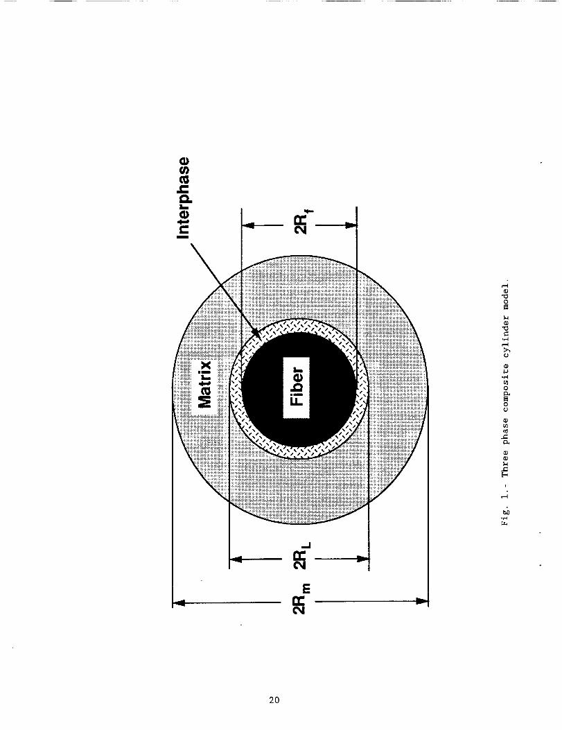
COMPOSITE CYLINDER MODEL
A three phase composite cylinder model is used in the present study to
discretely model the fiber, interphase layer and matrix (Fig. i). Each of the
three layers was treated as a homogeneous isotropic medium. The material
constants and outer radii for the fiber, layer, and matrix are distinguished by
subscripts f, L, and, m, respectively. The outer radius of the matrix (Rm) was
2 2chosen to achieve the appropriate fiber volume fraction, Vf - Rf/R m. A
parameter K was defined as the ratio (_/R_) and was used indimensionless the
analysis. A cylindrical coordinate system centered on the fiber with the z-axis
along the longitudinal fiber direction was used in the analysis. Axisymmetry
was imposed for the stresses and the displacements in all the cylinders. In the
fiber axial direction, a state of generalized plane strain was imposed. Thus,
the axial strain _ was assumedto be constant for all the three regions.ZZ
Loading was limited to uniform thermal loads. The formulation of the boundary
value problem is first presented, followed by (i) an exact implicit solution and
(ii) an approximate closed form solution to the equations.
Formulation
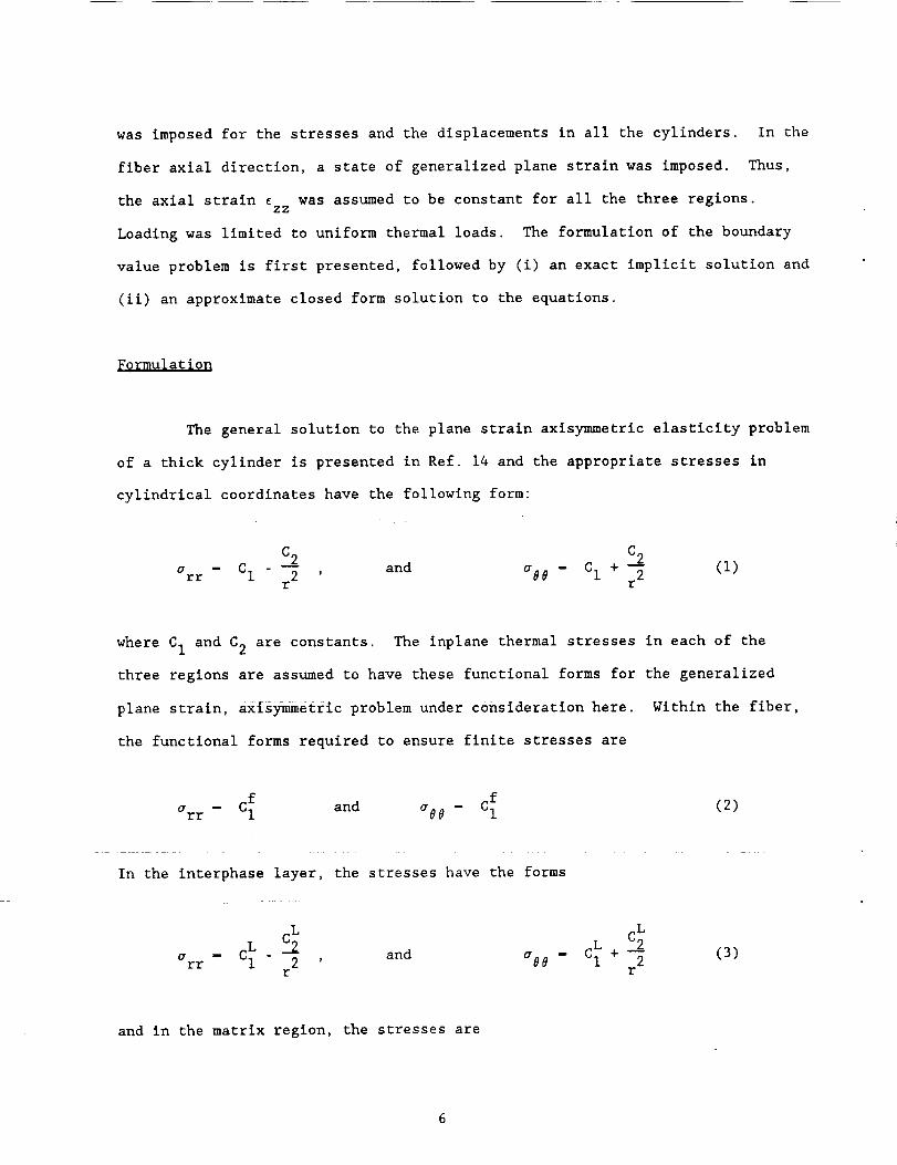
The general solution to the plane strain axis_etrlc elasticity problem
of a thick cylinder is presented in Ref. 14 and the appropriate stresses in
cylindrical coordinates have the following form:
C2arr - CI - _ , and a0e C I + C2r2
(i)
where CI and C2 are constants. The inplane thermal stresses in each of the
three regions are assumed to have these functional forms for the generalized
plane strain, ax_s_etric problem under consideration here. Within the fiber,
the functional forms required to ensure finite stresses are
f f- C_• and a0_ - CI (2)arr
In the interphase layer, the stresses have the forms
L LL C2 L C2
arr - CI - --_ , and aeO - C I + -_r r
(B)
and in the matrix region, the stresses are
m
m C2 m C_
arr - CI - -_ , and a00 - CI + 2r r
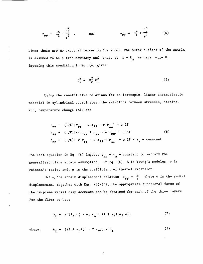
(4)
Since there are no external forces on the model, the outer surface of the matrix
is assumed to be a free boundary and, thus, at r - Rm we have arr- O.
Imposing this condition in Eq. (4) gives
m R2 m (5)C2 - m CI
Using the constitutive relations for an isotropie, linear thermoelastic
material in cylindrical coordinates, the relations between stresses, strains,
and, temperature change (AT) are
_rr - (I/E)[arr - v %8 - v Ozz] + _ AT
_00 - (I/E)[-u arr + %0 " v azz] + _ AT
Czz - (i/E)[-v Orr - w a08 + azz] + _ nT -- constant
a
(6)
The last equation in Eq. (6) imposes _zz - Ea - constant to satisfy the
generalized plane strain assumption. In Eq. (6), E is Young's modulus, u is
Poisson's ratio, and, _ is the coefficient of thermal expansion.
uUsing the strain-displacement relation, _98 - r
where u is the radial
displacement, together with Eqs. (2)-(6), the appropriate functional forms of
the in-plane radial displacements can be obtained for each of the three layers.
For the fiber we have
f uf E + (I + of AT]uf - r [Af CI - a vf)(7)
where, Af - [(i + vf)(l - 2 vf)] / Ef(8)
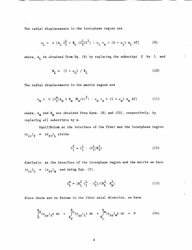
The radial displacements in the interphase region are
L (C_/r 2) - vL + (I + _L AT]uL - r [AL C I + BL _a VL) (9)
where, A L is obtained from Eq. (8) by replacing the subscript f by L and
BL - (I + VL) / EL (I0)
The radial displacements in the matrix region are
u r [C_(A m + B (Rm/r) 2}m - m Vm _a + (i + Vm) am AT] (II)
where, A and B are obtained from Eqns. (8) and (I0), respectively, bym m
replacing all subscripts by m.
Equilibrium at the interface of the fiber and the interphase region
(arr)f - (arr)L yields
f L L 2CI - C I - (C2/Rf) (12)
Similarly, at the interface of the interphase region and the matrix we have
(arr)L - (arr) m and using Eqn. (5),
m L _ C2]/[R2L. R2m]CI [R2L CI (13)
Since there are no forces in the fiber axial direction, we have
R L R_f(Ozz)fr dr + f (azz)Lr dr + fm(azz)mr dr
0 Rf RL
- 0 (14)

for each of the three layers from Eqn. (6) and simplifyingSubstituting azz
using Eqns. (5), (12) and (13) we have
where,
+ BI L L DI (15)AI _a Cl + Cl C2 -
A I - EfVf + ELVf(K - i) + Em(l - VfK)
- v K]B1 2 Vf[vf + VL(K - I) - m
2C 1 - 2 Vf(v m - vf)/Rf
D 1 - AT [Ef_fVf + EL_LVf(K -i ) + Em_m(l - VfK)]
Displacement compatibility at the fiber/interphase and the
interphase/matrix interfaces is imposed by
uf - uL at r - Rf and uL - um at r - RL(16)
Substituting Eqns. (7), (9) and (Ii) into Eqns. (16) and simplifying using Eqns.
(12) and (13) yields
where,
+ G L _ L (17)(vL- vf) _a CI + F (-I/R) C2 - TLf
G - Af - AL
F - Af + BL
TLf - AT [(i + vL) _L " (I + vf) of]
and
where
+ B3 L L(Vm" VL) _a CI + C3 C2 - TmL(18)
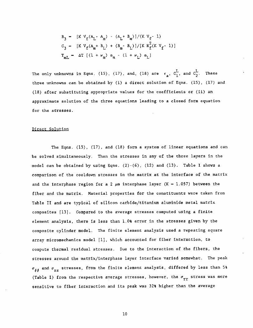
B 3 -
C 3 -
TmL -
[K Vf(A L- A m ) (AL+ Bm)]/(K Vf- i)
[K Vf(Am+ B L) + (B m- BL)]/[K R_(K Vf- i)]
AT [(i + v m) am (i + VL) =L]
L and L TheseThe only unknowns in Eqns. (15), (17), and, (18) are _a' Cl' C2'
three unknowns can be obtained by (i) a direct solution of Eqns. (15), (17) and
(18) after substituting appropriate values for the coefficients or (ii) an
approximate solution of the three equations leading to a closed form equation
for the stresses.
Direct Solution
The Eqns. (15), (17), and (18) form a system of linear equations and can
be solved simultaneously. Then the stresses in any of the three layers in the
model can be obtained by using Eqns. (2)-(6), (12) and (13). Table I shows a
comparison of the cooldown stresses in the matrix at the interface of the matrix
and the interphase region for a 2 #m interphase layer (K - 1.057) between the
fiber and the matrix. Material properties for the constituents were taken from
Table II and are typical of silicon carbide/titanium aluminide metal matrix
composites [13]. Compared to the average stresses computed using a finite
element analysis, there is less than 1.0% error in the stresses given by the
composite cylinder model. The finite element analysis used a repeating square
array micromechanics model [I], which accounted for fiber interaction, to
compute thermal residual stresses. Due to the interaction of the fibers, the
stresses around the matrix/interphase layer interface varied somewhat. The peak
a88 and azz stresses, from the finite element analysis, differed by less than 5%
(Table I) from the respective average stresses, however, the arr stress was more
sensitive to fiber interaction and its peak was 32% higher than the average
i0
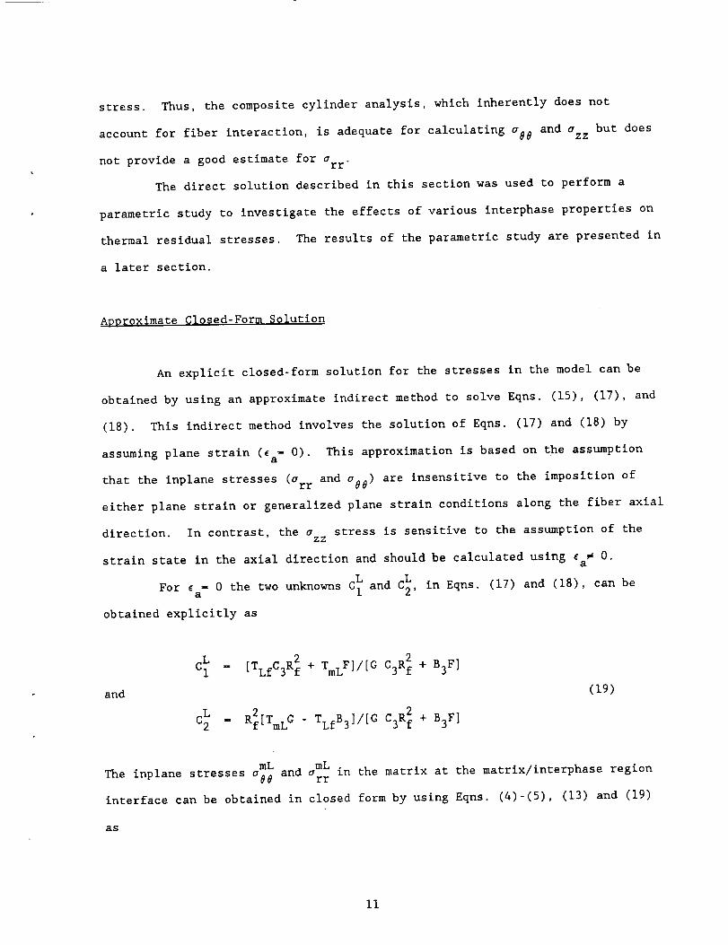
stress. Thus, the composite cylinder analysis, which inherently does not
account for fiber interaction, is adequate for calculating _88 and azz but does
not provide a good estimate for arr
The direct solution described in this section was used to perform a
parametric study to investigate the effects of various interphase properties on
thermal residual stresses. The results of the parametric study are presented in
a later section.
Approximate Closed-Form Solution
An explicit closed-form solution for the stresses in the model can be
obtained by using an approximate indirect method to solve Eqns. (15), (17), and
(18). This indirect method involves the solution of Eqns. (17) and (18) by
assuming plane strain (_a- 0). This approximation is based on the assumption
that the inplane stresses (Orr and a#0 ) are insensitive to the imposition of
either plane strain or generalized plane strain conditions along the fiber axial
direction. In contrast, the a stress is sensitive to the assumption of theEZ
strain state in the axial direction and should be calculated using _a _ O.
L and L in Eqns (17) and (18), can beFor _a- 0 the two unknowns C I C2, .
obtained explicitly as
L 2 C3R_ + B3F]C I - [TLfC3R f + TmLF]/[G
and (19)
c2L , R2[TmL G - TLfB 3]/[G C3R2 + B3F ]
mL mL .
The inplane stresses abe and arr in the matrix at the matrix/interphase region
interface can be obtained in closed form by using Eqns. (4)-(5), (13) and (19)
as
ii
and
where
AT (i + K Vf)
{VfK (Am - D) + Bm+ D }[C (I + vf) af + (I
mL mLarr - aoo[K Vf - I]/[K Vf + i]
C = [AL + BL]/[K F - G]
D - [K ALF + BLG]/[K F - G]
C)(I + VL) aL - (I + vm) am]
(20)
L L
An approximate value for ea can now be obtained by substituting C I and C2 from
m in the matrix region can then beEqn. (19) into Eqn. (15). The axial stress azz
obtained from Eqns. (4), (5), (6), (13), (15) and (19) as
mLm - - amAT ) + 2 v a K Vf i) (21)azz Em(ea m rr Vf/(K -
Table I shows stresses, computed using closed form Eqns. (20) and (21), in the
matrix at the interface of the matrix and the interphase region for a 2 #m
interphase layer (K - 1.057) between the fiber and the matrix. Material
properties were taken from Table II. Compared to the average stresses computed
using the finite element analysis the closed-form results differ by 5.3%, 4% and
2.5% for the arr, a88 and azz stresses, respectively.
For the case in which there is only fiber and matrix with no interphase
layer, Eqn. (20) can be used by substituting K - i, A L- Am , BL - Bm and a L - am
to obtain
a88 -
AT (i + Vf)
{Vf(Am_ Xf ) + Bm + Af}[(l + uf) af - (I + wm) am](22)
The expressions for arr and azz
substituting K - i.
can be obtained from Eqns. (20) and (21) by
12
The closed-form solutions presented in this section were used to develop
simplified guidelines to enable the (i) selection of fiber coating materials
that will minimize thermal residual stresses and (ii) calculation of the
percentage change in residual stresses due to the presence of an interphase
layer at the fiber/matrix interface. These guidelines are presented in a later
section.
PARAMETRIC STUDY
The composite cylinder model developed in the previous section provides
a simple means to study the sensitivity of thermal residual stresses to the
thermo-mechanical properties of the interphase region. The direct solution of
LEqns. (15), (17) and (18) was used to the determine the three unknowns ca, C I,
L The stresses in any of the three regions can then be calculated usingand, C2 .
Eqns. (2)-(6), (12) and (13). Since the stresses in the matrix would be the
largest at the matrix/interphase interface, only interfacial matrix stresses
were calculated for the present study. The fiber and the matrix properties
given in Table II were used in the parametric study and were kept constant while
the interphase region properties were varied. All stresses were normalized by
the temperature change, AT.
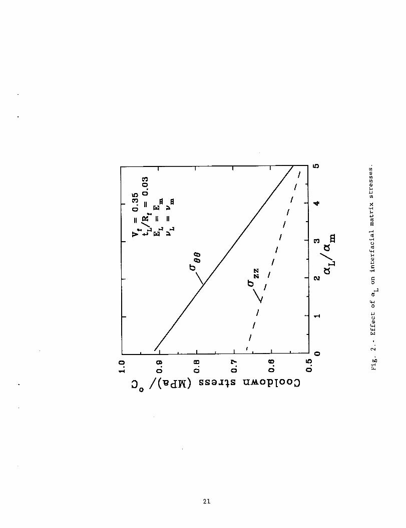
Fig. 2 shows the variation of o88 and azz in the matrix at the
matrix/interphase interface for a range of =L/em ratios. Since the arr
stresses in the matrix are compressive (see Table I), they would not lead to
premature matrix cracking during cooldown and were therefore not considered to
stresses however, are tensilebe important to this study. The o86 and azz
(Table I) and could lead to premature matrix cracking. For an interphase
(tL/Rf) ratio of 0.03 (i.e. 2_m coating on a 140_m diameter fiber), EL- Em and
vL- Vm, Fig. 2 shows that both a00 and azz decreased rapidly with increasing e L .
13
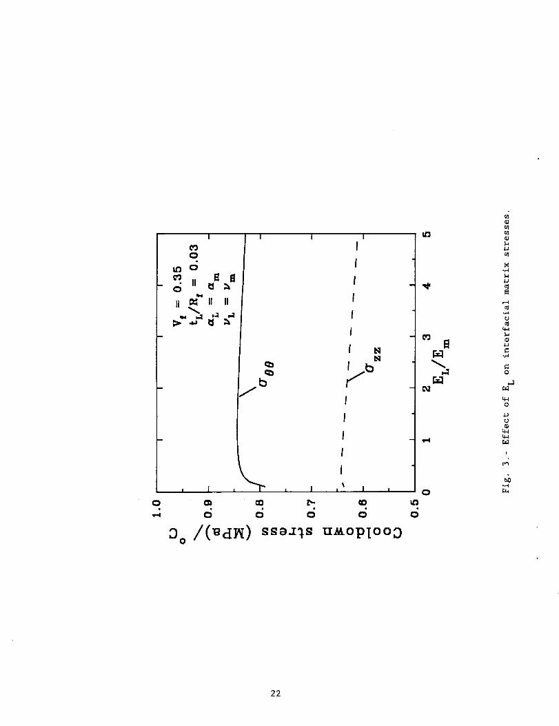
For the same(tL/R f) ratio, Fig. 3 shows that ace remained unchangedfor (EL/Em)
ratios greater than one and decreased for (EL/Em) ratios less than 0.5. The
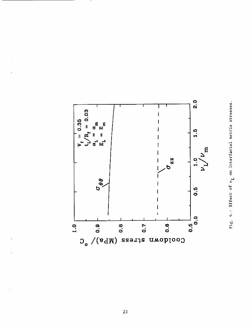
decreased with increasing EL The (VL/Vm) ratio had virtuallyaxial stress azz
no influence on a88 and azz in the matrix at the matrix/interphase interface as
shown in Fig 4 Note that in Figs 2-4, the _se stress is larger than the a• " ' " ZZ
stress by 20-30% over a wide range of interphase layer properties. Thus, for
the present composite, radial matrix cracking would be expected to occur in
preference to cracking perpendicular to the fiber during cooldown. Micrographs
for the silicon carbide/titanium alumlnide composite show evidence of radial
matrix cracks after consolidation [15] and confirm this prediction.
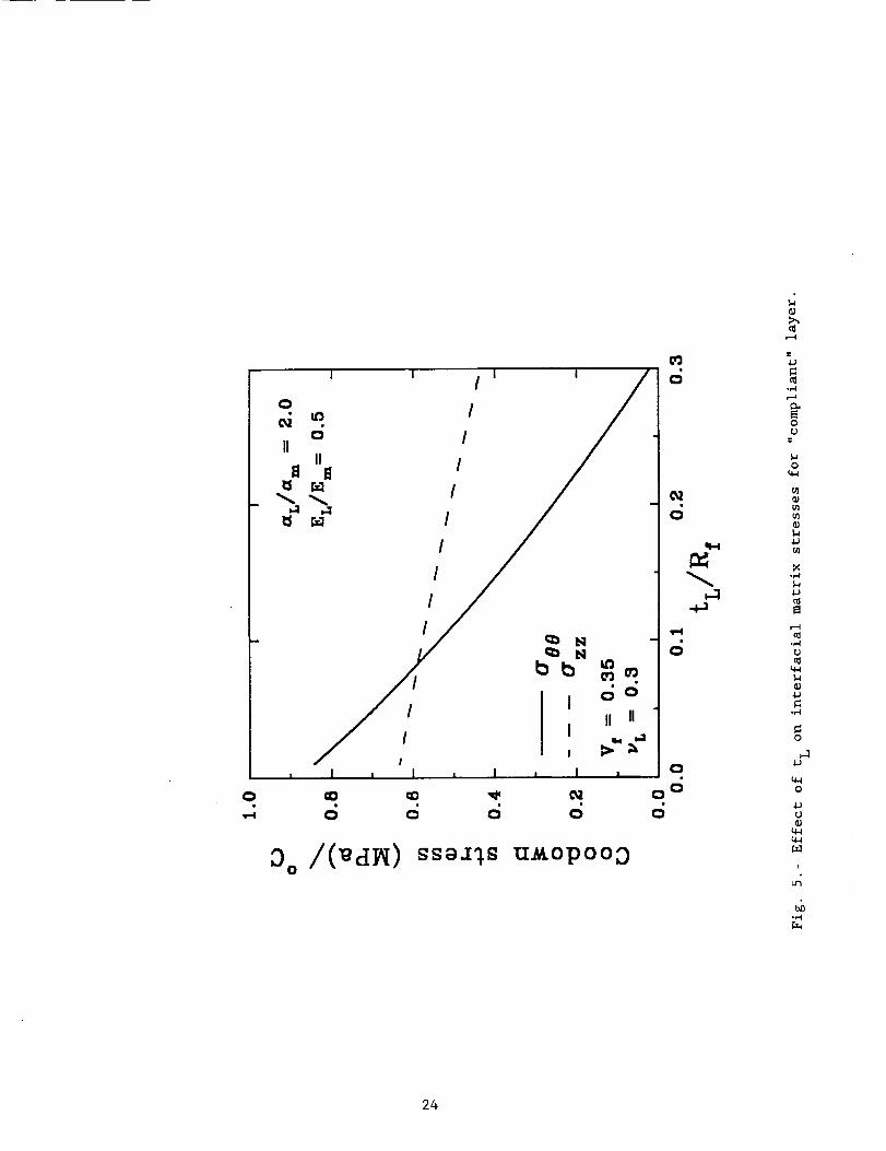
Fig. 5 shows that the thickness of the interphase layer (tL) influenced
the interfacial matrix stresses significantly. The a09 and Ozz decreased
rapidly for _L/=m- 2.0 and EL/Em = 0.5 with increasing (tL/Rf). Thus, for a
"compliant" interphase layer with a high CTE, there is an advantage in having a
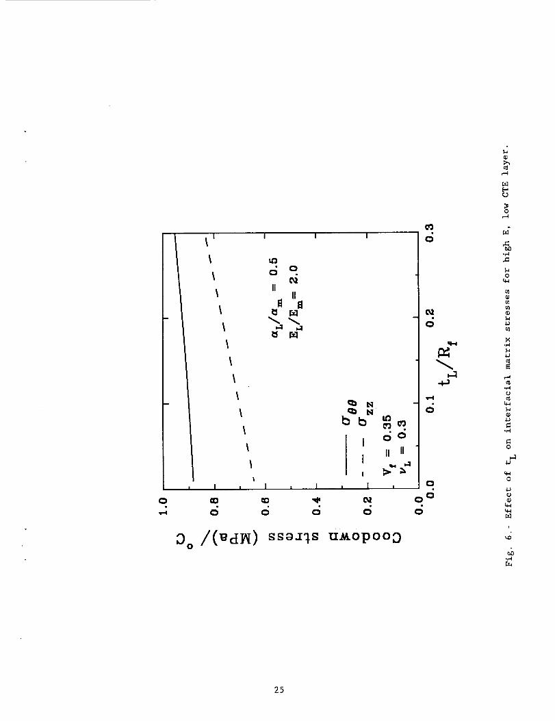
thick interphase layer. Fig. 6 shows that the stresses increased moderately for
_L/=m- 0.5 and EL/E m- 2.0 with increasing layer thickness. Thus, for a
"brittle" interphase layer with a high modulus and a low CTE, the thickness of
the layer should be as small as possible. In Ref. 2, higher thermal residual
stresses were measured after the formation of brittle reaction zones at the F/M
interface, as would be expected based on the results in Fig. 6.
In summary, the stresses in the matrix at the matrlx/interphase
interface were strongly influenced by a L and tL and moderately influenced by EL .
A thick interphase layer with a CTE greater than the matrix and a Young's
modulus less than that of the matrix will, in general, lead to lower tensile
thermal residual stresses. Note that the results in this study are based on an
elastic analysis. Plastic yielding of the interphase layer or the matrix could
alter some of the trends predicted by this analysis [i0].
14
GUIDELINES FOR INTERPHASE PROPERTIES
As shown in the previous section, the properties of the interphase layer
influence the interfacial matrix stresses in a rather complicated way. Simple
quantitative guidelines for selecting interphase properties that will result in
a reduction of tensile interfacial residual stresses will be very useful to the
materials engineer. The closed-form equations (20) and (22) derived in this
study lend themselves to the derivation of such simple guidelines.
The change in the interfacial matrix stress a88 due to the addition of
an interphase region can be obtained by subtracting Eqn. (20) from Eqn. (22).
The first term in braces {} for both these equations are very similar. It can
be shown that for (tL/R f) < 0.08 and 0.I < (EL/E f) < 0.8 the first terms in
Eqns. (20) and (22) differ by only 3.3%. Thus, for most practical purposes it
can be assumed that the first terms in the two equations are equal for tL and EL
within the constraints specified above. The percentage change (Aa) in the
interfacial matrix stress, _08, due to the addition of an interphase layer to a
fiber/matrix interface is given as:
(I - C)[(I + vL) _L" (I + vf) of]Aa - x i00 (23)
[(i + vm) am (i + vf) _f]
where i C - H (24)H + (i - VL)(Rf/t L)
EL (I + vf)(l 2vf)and H - I + (25)
Ef (i + _L )
Eqns. (23-25) can be used to determine, approximately, the percentage reduction
in a88 for a given set of interphase layer properties. Eqn. (23) could also be
15
rearranged to calculate interphase properties for a desired percentage reduction
(Ao) in a08.
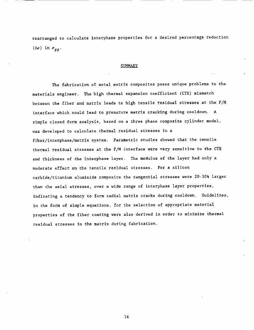
SUMMARY
The fabrication of metal matrix composites poses unique problems to the
materials engineer. The high thermal expansion coefficient (CTE) mismatch
between the fiber and matrix leads to high tensile residual stresses at the F/M
interface which could lead to premature matrix cracking during cooldown. A
simple closed form analysis, based on a three phase composite cylinder model,
was developed to calculate thermal residual stresses in a
fiber/interphase/matrlx system. Parametric studies showed that the tensile
thermal residual stresses at the F/M interface were very sensitive to the CTE
and thickness of the interphase layer. The modulus of the layer had only a
moderate effect on the tensile residual stresses. For a silicon
carbide/titanium aluminide composite the tangential stresses were 20-30% larger
than the axial stresses, over a wide range of interphase layer properties,
indicating a tendency to form radial matrix cracks during cooldown. Guidelines,
in the form of simple equations, for the selection of appropriate material
properties of the fiber coating were also derived in order to minimize thermal
residual stresses in the matrix during fabrication.
16

REFERENCES
I. A. L. Highsmith, D. Shin and R. A. Naik, "Local Stresses in Metal Matrix
Composites Subjected to Thermal and Mechanical Loading," Thermal and
Mechanical Behavior of Ceramic and Metal Matrix Composites, ASTM STP 1080,
J. M. Kennedy, H. H. Moeller, and W. S. Johnson, Eds., American Society for
Testing and Materials, Philadelphia, 1990, pp. 3-19.
2. R. A. Naik, W. D. Pollock, and W. S. Johnson, "Effect of a High Temperature
cycle on the Mechanical Properties of Silicon Carbide/Titanium Metal Matrix
Composites," J. Materials Science, vol. 26, 1991, pp. 2913-2920.
3. C. G. Rhodes and R. A. Spurling, "Fiber-matrix Reaction Zone Growth Kinetics
in SiC-Reinforced Ti-6AI-4V as Studied by Transmission Electron Microscopy,"
ASTM STP 864, J. R. Vinson and M. Taya, Eds., American Society for Testing
and Materials, Philadelphia, PA, 1985, pp. 585-599.
4. L. J. Walpole, "A Coated Inclusion in an Elastic Medium," Math. Proc. Camb.
Phil. Soc., vol. 83, 1978, pp. 495-506.
5. Y. Mikata and M. Taya, "Stress Field in a Coated Continuous Fiber Composite
Subjected to Thermo-mechanical Loadings," J, Comp, Mat,, Vol. 19, Nov. 1985,
pp. 554-578.
6. J. A. Nairn, "Thermoelastic Analysis of Residual Stresses in Unidirectional,
High-Performance Composites," Polymer Composites, vol. 6, No. 2, 1985, pp.
123-130.
7. N. J. Pagano and G. P. Tandon, "Elastic Response of Multi-directional
Coated-fiber Composites," Composites Science and Technology, vol. 31, 1988,
pp. 273-293.
8. E. Sideridis, "The In-Plane Shear Modulus of Fibre Reinforced Composites as
Defined by the Concept of Interphase," Compos_¢es Science and Technology,
vol. 31, 1988, pp. 35-53.
17
9. Y. Benveniste, G. J. Dvorak and T. Chen, "Stress Fields in Compositeswith
Coated Inclusions," Mechanics of Materials, vol. 7, 1989, pp. 305-317.
I0. S. M. Arnold, V. K. Arya and M. E. Melis, "Elastlc/Plastic Analyses of
Advanced Composites Investigating the Use of the Compliant Layer Concept in
Reducing Residual Stresses Resulting for Processing," NASA TM 103204, Sept.
1990, National Aeronautics and Space Administration, Cleveland, Ohio.
ii. L. J. Broutman and B. D. Agarwal, "A Theoretical Study of the Effect of an
Interfacial Layer on the Properties of Composites," Polymer Engineering and
Science, Aug. 1974, vol. 14, No. 8, pp. 581-588.
12. J. J. Caruso, C. C. Chamis, and H. C. Brown, "Parametric Studies to
Determine the Effect of Compliant Layers on Metal Matrix Composite Systems,"
NASA TM-I02465, Jan. 1990, National Aeronautics and Space Administration,
Cleveland, Ohio.
13. R. A. Naik, W. S. Johnson and D. L. Dicus, "Micromechanical Thermal Analysis
of Interphase Region in a Titanium Alumlnide MMC," Titanium Aluminide
Composites, P. R. Smith, S. J. Balsone and T. Nicholas, Eds., WL-TR-91-4020,
Wright Laboratory, WPAFB, Ohio, Feb. 1991, pp, 563-575.
14. S. P. Timoshenko and J. N. Goodier, Theory of Elasticity, 3rd ed., McGraw-
Hill, New York, 1976, pg. 69.
15. J. A. Craves and C. C. Bampton, "Direct Consolidation of Titanium Aluminide
Matrix Composites Using Blended Powder," NASP Contractor Report 1051, NASA
Langley Research Center, National Aeronautics and Space Administration, Jun.
1989.
18
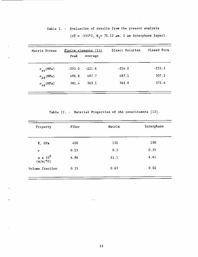
Table I. - Evaluation of results from the present analysis
(AT - -555°C, Rf= 71.12 #m, 2 #minterphase layer).
Matrix Stress Finite elements [13]
Peak Average
Direct Solution Closed Form
arr(MPa ) -293.0 -221.6 -224.0
o88(MPa ) 496.8 487.7 487.1
azz(MPa ) 381.4 363.1 361.8
-233.3
507.2
372.4
Table II. Material Properties of the constituents [13].
Property Fiber Matrix Interphase
E, GPa 400 132 190
v 0.25 0.3 0.35
x 106 4.86 ii.i 6.61
(m/m/°C)
Volume fraction 0.35 0.63 0.02
19
...Io-
Eo- v
0
r'_
0
U_
0
0_
oO
OJ
0_
o,
t
°_,.,I
2O
I
I
/
I
/
Oo /(_c[]_) ss_-T'_s uaopTooo
OJ
o_oJ
.,..4
°_e)
_o
,r4
0
o
0
¢J
_-_
b.]
i
_4
°,-.t
21
0
I
0
II _ II II
6 d
bJ
0o/(_a_)
i !
L_
d
ssa-_s
I
I
I
I
I
I
I
I NIQ
2 °!
I
I
I
I
i _ I I
d
_opTooD
0
0
X°,-I
,,-IU
°_1
0
0
U
|
,,.4
22
I I
Oo /(_a_) ss_s u_oplooo
0
N
o_
o
400_
U
q_
(I}
0
o_o
o
i
.,.4
23
0i
I
I
I
I
I
!
I
!
I
I
0o/(_d_) ss_s uaopooo
L0_,,-4,.--4
O,
0
r,
0t_
OJ_nulcD
4Ju_
X
0_
,.-.4
.,-4
U
OJ40
.,=I
0
40
0
U
u_
r
L.n
,r-,I
24
0
!
o
IIII
%
I i
0
oOII II
HN
bb
I
I
!
i I
d
, 1 i I ,
6 o
0o/(_d_) ssa-,Isuaopooo
CO
6
O_
d
+o
6
o
o0
6
rj
or-4
J
°_
0
N
o
u_
.IJ
0
o
,IJ0
i
°_..I
25
Report Documentation Page
i. Report No.
NASA CR- 1875994. Title and Subtitle
2. Government Accession No. 3. Recipient's Catalog No.
5. Report Date
Sememher 1991
Simplified Micromechanical Equations for ThermalResidual Stress Analysis of Coated Fiber Composites
7. Author(s)
R. A. Naik
9. Performing Organization Name and Address
Analytical Services and Materials, Inc.Hampton, VA 23665-5225
12. Sponsoring Agency Name and Address
National Aeronautics and Space AdministrationLangley Research CenterHampton, VA 23665-5225
6. Performing Organization Code
8, Performing Organization Report No.
10, Work Unit No.
505-63-50-04
11, Contract or Grant No.
NAS 1-18599
13. Type of Report and Period Covered
Contractor Report
14. Sponsoring Agency Code
15. Supplementary Notes
Langley Technical Monitor: C.E. Harris
16, Abstract
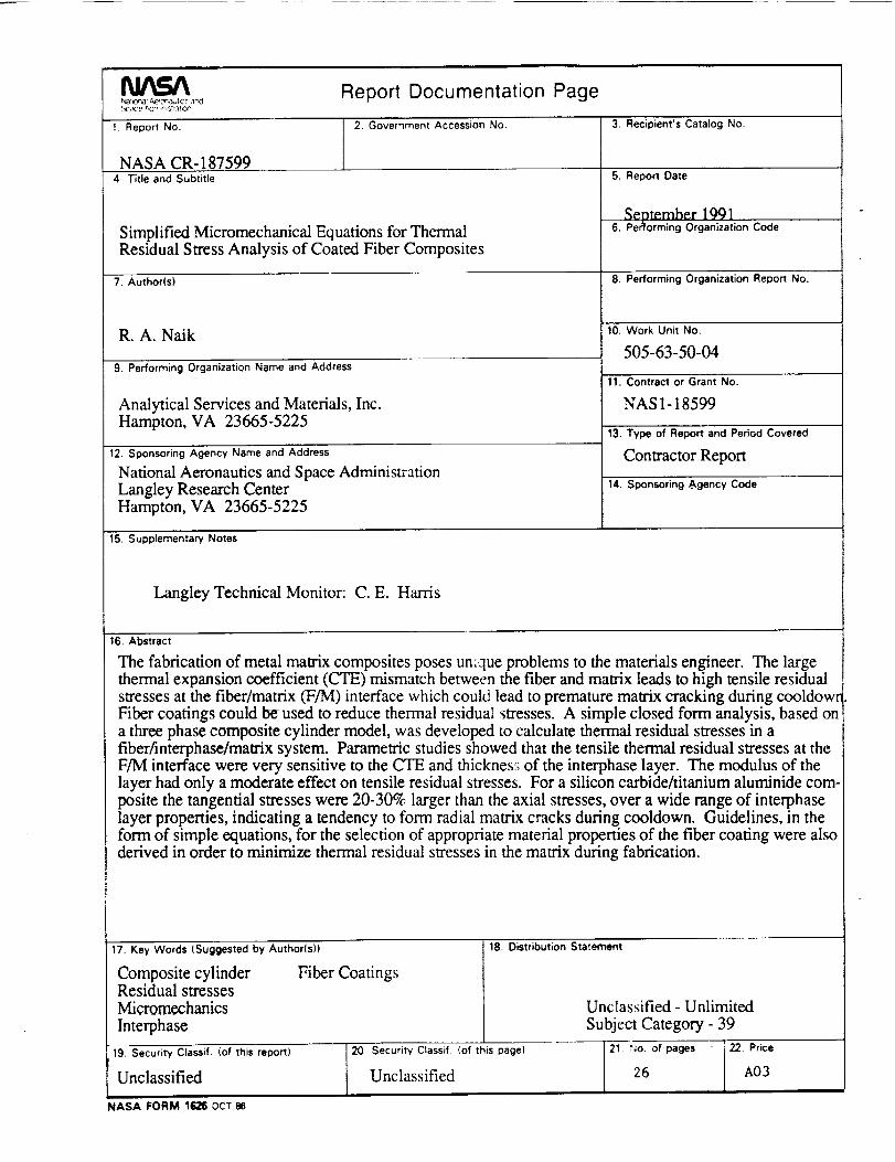
The fabrication of metal matrix composites poses unique problems to the materials engineer. The largethermal expansion coefficient (CTE) mismatch between the fiber and matrix leads to high tensile residualstresses at the fiber/matrix (F/M) interface which could lead to premature matrix cracking during cooldowrlFiber coatings could be used to reduce thermal residual stresses. A simple closed form analysis, based ona three phase composite cylinder model, was developed to calculate thermal residual stresses in afiber/interphase/matrix system. Parametric studies showed that the tensile thermal residual stresses at theF/M interface were very sensitive to the CTE and thicknes:; of the interphase layer. The modulus of thelayer had only a moderate effect on tensile residual stresses. For a silicon carbide/titanium aluminide com-posite the tangential stresses were 20-30% larger than the axial stresses, over a wide range of interphaselayer properties, indicating a tendency to form radial matrix cracks during cooldown. Guidelines, in theform of simple equations, for the selection of appropriate material properties of the fiber coating were alsoderived in order to minimize thermal residual stresses in the matrix during fabrication.
17, Key Words (Suggested by Authorls))
Composite cylinder Fiber CoatingsResidual stressesMicromechanics
Interphase,r,
19. Security Classif. (of this report)
Unclassified
18. Distribution Statement
Unclassified - Unlimited
Subject Category - 39
20. Security Classill =(of this page)
Unclassified
21. ;Jo. of pages
26
22. Price
A03
NASA FORM 1626 OCT 86