Embed Size (px)
Citation preview

Acta Polytechnica Vol. 52 No. 6/2012
Micromechanical Analysis of Cement Paste with Carbon Nanotubes
Vít Šmilauer, Petr Hlaváček, Pavel Padevět
Czech Technical University in Prague, Faculty of Civil Engineering, Department of Mechanics, Thákurova 7, 166 29Prague 6, Czech Republic
Corresponding author: [email protected]
AbstractCarbon nanotubes (CNT) are an attractive reinforcement material for several composites, due to their inherently highstrength and high modulus of elasticity. There are controversial results for cement paste with admixed CNT up to 500µmin length. Some results show an increase in flexural or compressive strength, while others showing a decrease in the values.Our experiments produced results that showed a small increase in fracture energy and tensile strength. Micromechanicalsimulations on a CNT-reinforced cement paste 50× 50 µm proved that CNT clustering is the crucial factor for an increasein fracture energy and for an improvement in tensile strength.
Keywords: carbon nanotubes, cement hybrid material, micromechanics, fracture energy.
1 Introduction
Worldwide production of cement has increased signif-icantly in recent years, due to the growing demandfor concrete. In 2010, 3.3 · 109 tons of cement wereproduced, which is three times the quantity of 1.1 ·109
tons produced in 1990. For reasons of sustainabilityand profitability, secondary cementitious materialshave been introduced into the binder, reducing theamount of Portland clinker in the cement. A furtherreduction can be made if the strength of the hydratedcement increases.Carbon nanofibers (CNF) and carbon nanotubes
(CNT) are a feasible approach to the production of ahigh strength binder, as has been demonstrated forcomposites [3, 19] and specifically for cement pastes[2, 4, 5, 9, 12]. Theoretical and experimental studieshave indicated that CNT exhibit Young modulus from180 to 588GPa and tensile strength in the rangebetween 2000 and 6140MPa [10]. Both CNT andCNF as admixtures are very difficult to distributeuniformly, even within a small volume of cement paste.Flocculation make it impossible to obtain improvedproperties of composite materials, unless a specialtreatment is applied.It is a challenging task to achieve good dispersion
of CNT/CNF in a cement matrix. A simple pow-der mixing procedure leads to poor dispersal of thecarbon nanomaterials in a cement paste. For thisreason, Sanchez and Ince proposed adding silica fumeto cement to increase the dispersiveness of CNF [15].Dispersion of CNT/CNF in water using surfactantsis another method, and is a widely-used way to intro-duce carbon nanomaterials into polymers [2]. How-ever, most surfactants and additives interfere withthe hydration reaction of cement, and usually prolong
Figure 1: CNT synthesized on the surface of a ce-ment grain. The image is 115µm in width. Image byK. Hruška, Institute of Physics ASCR, Prague.
the cement setting and hardening times.Another way to enhance the dispersiveness of
CNT/CNF is by functionalizing them. The carboxylor hydroxyl groups attached to the surface of car-bon that form during oxidation treatment can createbonds between the matrix and carbon nanomaterials.Functionalized CNT have already been proven to in-fluence the mechanical properties of hydrated cementpaste [2, 5].
Another method uses CNT directly synthesized onthe surface of cement grains [12], see Figure 1. Cementhybrid material (CHM) of this type can easily beblended with conventional cement. This procedureguarantees dispersion of CNT in the cement matrix.It has been reported that even a small mass fractionof CNT/cement = 0.005 helped to increase flexuralstrength by 22% [5].
22
Acta Polytechnica Vol. 52 No. 6/2012
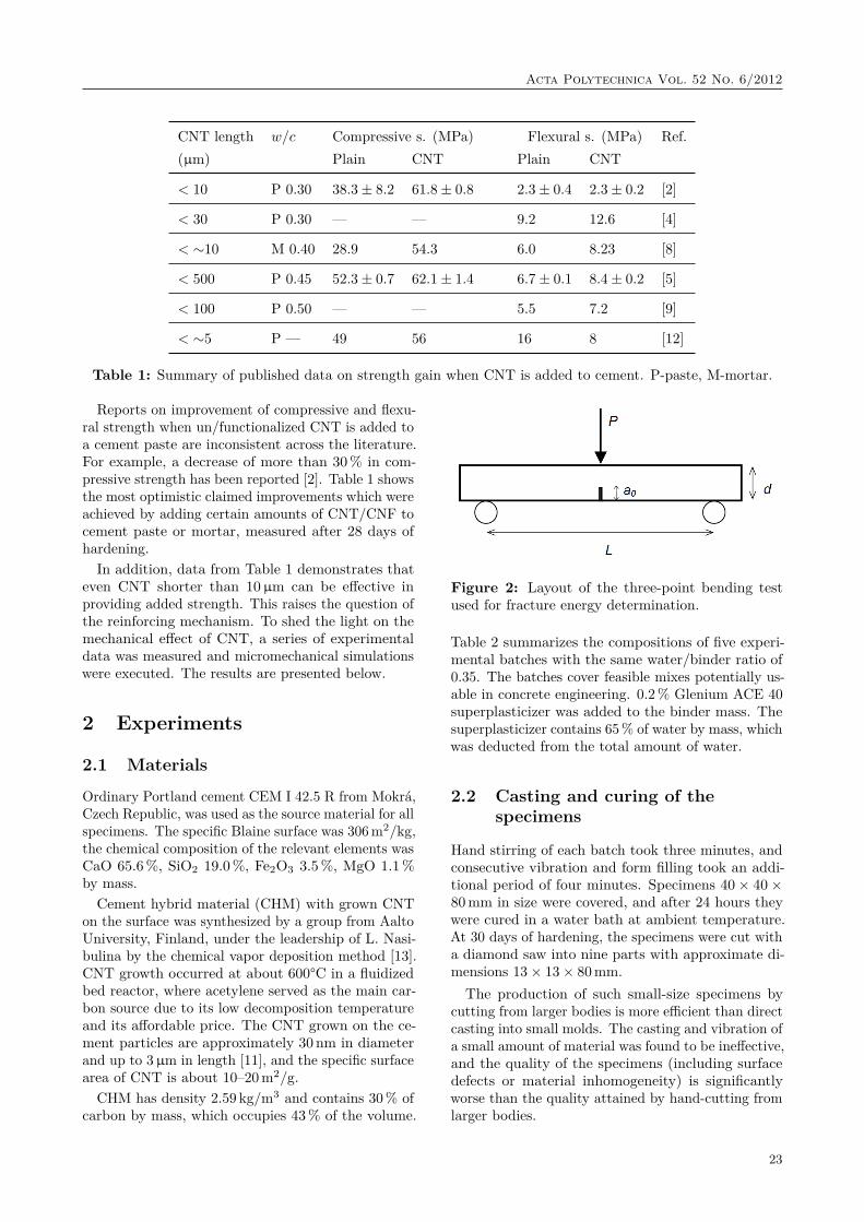
CNT length w/c Compressive s. (MPa) Flexural s. (MPa) Ref.(µm) Plain CNT Plain CNT
< 10 P 0.30 38.3± 8.2 61.8± 0.8 2.3± 0.4 2.3± 0.2 [2]
< 30 P 0.30 — — 9.2 12.6 [4]
< ∼10 M 0.40 28.9 54.3 6.0 8.23 [8]
< 500 P 0.45 52.3± 0.7 62.1± 1.4 6.7 ± 0.1 8.4± 0.2 [5]
< 100 P 0.50 — — 5.5 7.2 [9]
< ∼5 P — 49 56 16 8 [12]
Table 1: Summary of published data on strength gain when CNT is added to cement. P-paste, M-mortar.
Reports on improvement of compressive and flexu-ral strength when un/functionalized CNT is added toa cement paste are inconsistent across the literature.For example, a decrease of more than 30% in com-pressive strength has been reported [2]. Table 1 showsthe most optimistic claimed improvements which wereachieved by adding certain amounts of CNT/CNF tocement paste or mortar, measured after 28 days ofhardening.In addition, data from Table 1 demonstrates that
even CNT shorter than 10µm can be effective inproviding added strength. This raises the question ofthe reinforcing mechanism. To shed the light on themechanical effect of CNT, a series of experimentaldata was measured and micromechanical simulationswere executed. The results are presented below.
2 Experiments
2.1 Materials
Ordinary Portland cement CEM I 42.5 R from Mokrá,Czech Republic, was used as the source material for allspecimens. The specific Blaine surface was 306 m2/kg,the chemical composition of the relevant elements wasCaO 65.6%, SiO2 19.0%, Fe2O3 3.5%, MgO 1.1%by mass.Cement hybrid material (CHM) with grown CNT
on the surface was synthesized by a group from AaltoUniversity, Finland, under the leadership of L. Nasi-bulina by the chemical vapor deposition method [13].CNT growth occurred at about 600°C in a fluidizedbed reactor, where acetylene served as the main car-bon source due to its low decomposition temperatureand its affordable price. The CNT grown on the ce-ment particles are approximately 30 nm in diameterand up to 3µm in length [11], and the specific surfacearea of CNT is about 10–20m2/g.
CHM has density 2.59 kg/m3 and contains 30% ofcarbon by mass, which occupies 43% of the volume.
Figure 2: Layout of the three-point bending testused for fracture energy determination.
Table 2 summarizes the compositions of five experi-mental batches with the same water/binder ratio of0.35. The batches cover feasible mixes potentially us-able in concrete engineering. 0.2% Glenium ACE 40superplasticizer was added to the binder mass. Thesuperplasticizer contains 65% of water by mass, whichwas deducted from the total amount of water.
2.2 Casting and curing of thespecimens
Hand stirring of each batch took three minutes, andconsecutive vibration and form filling took an addi-tional period of four minutes. Specimens 40× 40×80mm in size were covered, and after 24 hours theywere cured in a water bath at ambient temperature.At 30 days of hardening, the specimens were cut witha diamond saw into nine parts with approximate di-mensions 13× 13× 80mm.The production of such small-size specimens by
cutting from larger bodies is more efficient than directcasting into small molds. The casting and vibration ofa small amount of material was found to be ineffective,and the quality of the specimens (including surfacedefects or material inhomogeneity) is significantlyworse than the quality attained by hand-cutting fromlarger bodies.
23
Acta Polytechnica Vol. 52 No. 6/2012
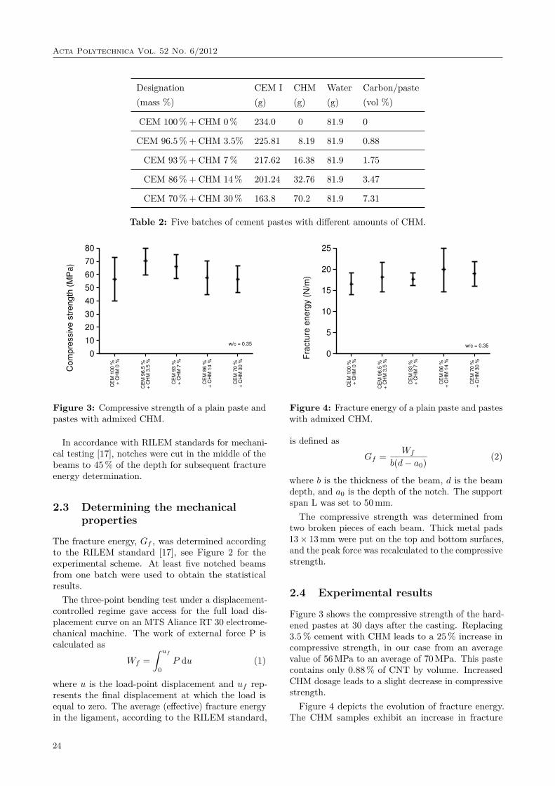
Designation CEM I CHM Water Carbon/paste(mass %) (g) (g) (g) (vol %)
CEM 100 % + CHM 0 % 234.0 0 81.9 0
CEM 96.5 % + CHM 3.5% 225.81 8.19 81.9 0.88
CEM 93 % + CHM 7 % 217.62 16.38 81.9 1.75
CEM 86 % + CHM 14 % 201.24 32.76 81.9 3.47
CEM 70 % + CHM 30 % 163.8 70.2 81.9 7.31
Table 2: Five batches of cement pastes with different amounts of CHM.
0
10
20
30
40
50
60
70
80
CE
M 1
00 %
+
CH
M 0
%
CE
M 9
6.5
%
+ C
HM
3.5
%
CE
M 9
3 %
+
CH
M 7
%
CE
M 8
6 %
+
CH
M 1
4 %
CE
M 7
0 %
+
CH
M 3
0 %
Com
pre
ssiv
e s
trength
(M
Pa)
w/c = 0.35
Figure 3: Compressive strength of a plain paste andpastes with admixed CHM.
In accordance with RILEM standards for mechani-cal testing [17], notches were cut in the middle of thebeams to 45% of the depth for subsequent fractureenergy determination.
2.3 Determining the mechanicalproperties
The fracture energy, Gf , was determined accordingto the RILEM standard [17], see Figure 2 for theexperimental scheme. At least five notched beamsfrom one batch were used to obtain the statisticalresults.
The three-point bending test under a displacement-controlled regime gave access for the full load dis-placement curve on an MTS Aliance RT 30 electrome-chanical machine. The work of external force P iscalculated as
Wf =∫ uf
0P du (1)
where u is the load-point displacement and uf rep-resents the final displacement at which the load isequal to zero. The average (effective) fracture energyin the ligament, according to the RILEM standard,
0
5
10
15
20
25
CE
M 1
00 %
+
CH
M 0
%
CE
M 9
6.5
%
+ C
HM
3.5
%
CE
M 9
3 %
+
CH
M 7
%
CE
M 8
6 %
+
CH
M 1
4 %
CE
M 7
0 %
+
CH
M 3
0 %
Fra
ctu
re e
nerg
y (
N/m
)
w/c = 0.35
Figure 4: Fracture energy of a plain paste and pasteswith admixed CHM.
is defined asGf = Wf
b(d− a0) (2)
where b is the thickness of the beam, d is the beamdepth, and a0 is the depth of the notch. The supportspan L was set to 50mm.The compressive strength was determined from
two broken pieces of each beam. Thick metal pads13× 13mm were put on the top and bottom surfaces,and the peak force was recalculated to the compressivestrength.
2.4 Experimental results
Figure 3 shows the compressive strength of the hard-ened pastes at 30 days after the casting. Replacing3.5% cement with CHM leads to a 25% increase incompressive strength, in our case from an averagevalue of 56MPa to an average of 70MPa. This pastecontains only 0.88% of CNT by volume. IncreasedCHM dosage leads to a slight decrease in compressivestrength.Figure 4 depicts the evolution of fracture energy.
The CHM samples exhibit an increase in fracture
24

Acta Polytechnica Vol. 52 No. 6/2012
Component E (GPa) ν ft (MPa) Gf (N/m)
Porosity 0.2 0.02 — —
Clinker 135 0.3 1800 118.5
Products 21.7 0.24 5.58 11.5
CNT 231 0.14 3000 200
Table 3: Elastic and fracture properties of the components.
energy even in a small amount of replacement. Re-placing 3.5% of the cement by CHM causes a 14%increase in the fracture energy.
It should be added that a variation in CHM contenthas consequences for workability, paste density andporosity. The results indicate that the classical CNTpull-out or crack bridging mechanism does not occur.Microcrack shielding seems to be the most relevantmechanism operating in hardened cement paste rein-forced by short CNT, giving only a slight increase inthe fracture energy [7]. In contrast, PVA-reinforcedcement-based composites with fibers several millime-ters in length yield fracture energy that is higher byorders of magnitude [6]. This experimental findingis further supported by micromechanical simulationsthat show a certain increase in the upper-bound frac-ture energy.
3 Micromechanical simulations
2D micromechanical simulations aimed to repro-duce the fracture energy from CNT-free and CNT-reinforced cement pastes and, in addition, to ex-plore the role of clustering and CNT length. TheCEMHYD3D cement hydration model generated the3D microstructure of hydrated cement paste, fromwhich a 2D slice 50× 50 µm was taken. Various chem-ical phases were reduced to three components; capil-lary porosity, clinker minerals and hydration products,which correspond mainly to C-S-H. For 30 days ofhydration, the volume fractions yield to 14.2%, 11.6%and 74.2% respectively. The CNT volume fractionwas considered as 3.47%, which corresponds to acomposition of CEM 86 % + CHM 14 %.
CNT fibers were introduced as 1D truss elements,connecting particular nodes of 2D quadrilateral ele-ments. Each fiber is represented by one finite elementwithout intermediate hanging nodes, in order to sim-plify the model.
An isotropic damage material model is assigned toall four components. A simple cohesive crack modelwith linear strain softening and Mazars’ measure of
strain is used:
σ = (1− ω)Eε = ft
(1− hωεft
2Gf
), (3)
ε̃ =
√√√√ 3∑I=1〈εI〉2, (4)
where σ is the normal stress transferred across acohesive crack, ft is the uniaxial tensile strength, h isthe effective width of a finite element, ε is the normalstrain to a crack, Gf is the mode-I fracture energy,and ω is the damage parameter. 〈εI〉 are positiveparts of the principal values of the strain tensor ε.Equation (3) leads to an explicit evaluation of damageparameter ω.
Table 3 summarizes the elastic and fracture proper-ties of the four components. The elastic modulus ofporosity was assigned a finite value, since this speedsup convergence. It was checked that a further reduc-tion of the modulus leads to negligible changes inresults. Clinker minerals are crystalline phases withhigh tensile strength and normally suffer no damageduring loading. Their fracture energy is recalculatedfrom scratch-test results [18].The properties of CNT are estimated on the basis
of recent results [16]. Hydration products, mainlyC-S-H, are taken as the low-density type of C-S-H [1].The C-S-H tensile strength and the C-S-H fracture en-ergy were deduced from experimental data and a 2Dsimulation of plain paste. These two parameters wereidentified by means of an inverse-problem, taking themost reasonable case of the two weakly dependent pa-rameters; flexural strength assuming 5.8MPa, similarto [5, 8], and for fracture energy assuming 16.5N/mas determined from our lab tests, see Figure 4.
Figure 5 depicts microstructure images for microme-chanical simulations. As mentioned above, a composi-tion of CEM 86 % +CHM 14% was considered for allcases, with the exception of plain paste. The cross-section of one CNT truss element was 50 nm times1µm, which in fact represents a bundle of CNT, nota single nanotube. The CNT length was randomizedaccording to uniform distribution and length limit.The orientation of the CNT fibers is also random.Gaussian distribution of CNT fibers in a cluster was
25
Acta Polytechnica Vol. 52 No. 6/2012
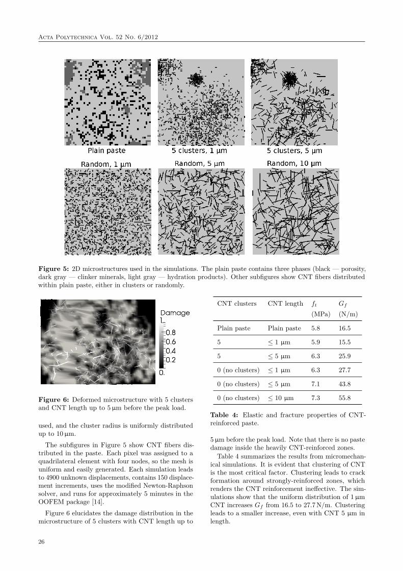
Figure 5: 2D microstructures used in the simulations. The plain paste contains three phases (black — porosity,dark gray — clinker minerals, light gray — hydration products). Other subfigures show CNT fibers distributedwithin plain paste, either in clusters or randomly.
Figure 6: Deformed microstructure with 5 clustersand CNT length up to 5µm before the peak load.
used, and the cluster radius is uniformly distributedup to 10µm.The subfigures in Figure 5 show CNT fibers dis-
tributed in the paste. Each pixel was assigned to aquadrilateral element with four nodes, so the mesh isuniform and easily generated. Each simulation leadsto 4900 unknown displacements, contains 150 displace-ment increments, uses the modified Newton-Raphsonsolver, and runs for approximately 5 minutes in theOOFEM package [14].
Figure 6 elucidates the damage distribution in themicrostructure of 5 clusters with CNT length up to
CNT clusters CNT length ft Gf
(MPa) (N/m)
Plain paste Plain paste 5.8 16.5
5 ≤ 1 µm 5.9 15.5
5 ≤ 5 µm 6.3 25.9
0 (no clusters) ≤ 1 µm 6.3 27.7
0 (no clusters) ≤ 5 µm 7.1 43.8
0 (no clusters) ≤ 10 µm 7.3 55.8
Table 4: Elastic and fracture properties of CNT-reinforced paste.
5µm before the peak load. Note that there is no pastedamage inside the heavily CNT-reinforced zones.
Table 4 summarizes the results from micromechan-ical simulations. It is evident that clustering of CNTis the most critical factor. Clustering leads to crackformation around strongly-reinforced zones, whichrenders the CNT reinforcement ineffective. The sim-ulations show that the uniform distribution of 1µmCNT increases Gf from 16.5 to 27.7N/m. Clusteringleads to a smaller increase, even with CNT 5 µm inlength.
26

Acta Polytechnica Vol. 52 No. 6/2012
0
1
2
3
4
5
6
7
8
0 50 100 150 200 250 300 350 400
Ave
rag
e t
en
sile
str
ess (
MP
a)
Average strain in loading direction • 10-3
(-)
0 clusters - 10 µm0 clusters - 5 µm0 clusters - 1 µm5 clusters - 5 µm5 clusters - 1 µm
Plain paste
Figure 7: A stress-strain diagram for loaded mi-crostructures.
Figure 7 plots the stress-strain diagram for plainand CNT-reinforced pastes. Note that there is notmuch increase in flexural strength but there is a sig-nificant improvement in ductility, which is reflectedas an increase in fracture energy.
Addition of CNT to cement paste, in any form, leadsnecessarily to clustering. According to the Powersmodel of cement hydration, the CNT-unreinforced vol-ume corresponds to the initial volume of unhydratedcement grains, where CNT cannot enter during initialmixing. The initial volume fraction of the clinkercorresponds to
fclinker = 0.32w/c+ 0.32 , (5)
which for w/c = 0.35 yields 48%. This large volumeremains unreinforced and prevents uniform distribu-tion of CNT fibers. This explains why our exper-imental fracture energy is always lower than whenmicromechanical predictions with a uniform CNT dis-tribution are used.Further simulations with variable CHM content
support the hypothesis that CNT clustering lowersthe amount of fracture energy. Figure 8 shows thatplacing CNT only outside of originally unhydratedcement grains corresponds well with the experimentalresults. Cement paste with 30% CHM shows discrep-ancy with micromechanical simulation, the reasonlies probably in lower workability and extensive CNTseparation during mixing.
4 ConclusionsThe role of CNT reinforcement in cement paste pro-vides another option for improving the quasi-brittlebehavior of cementitious materials. Experimental evi-dence shows a marginal improvement in compressivestrength and fracture energy. As has been provenby numerical simulations, the clustering of CNT in
0
20
40
60
80
100
CE
M 1
00 %
+
CH
M 0
%
CE
M 9
6.5
%
+ C
HM
3.5
%
CE
M 9
3 %
+
CH
M 7
%
CE
M 8
6 %
+
CH
M 1
4 %
CE
M 7
0 %
+
CH
M 3
0 %
Fra
ctu
re e
nerg
y [N
/m]
w/c=0.35
CNT everywhere
CNT outside of cement grains
Measured data
Figure 8: Fracture energy of pastes with variableCHM content (CNT length up to 3µm). Microme-chanical simulations with average CNT length up to2.5µm consider CNT placement everywhere or only inareas outside of originally unhydrated cement grains.
the paste microstructure is the crucial factor, due tothe presence of unreacted cement grains in the initialmixture and the intermixing of CHM with ordinarycement. However, micromechanical simulations showthat a uniform distribution CNT fibers only 1µm inlength may increase the fracture energy from 16.5 to27.7N/m, and the flexural strength up to 10%.
Direct synthesis of CNT on the surface of cementparticles solved the problem with flocculation of CNTseparately added to the cement paste, but the prob-lem of initially unhydrated grains remained. Theclaimed twofold increase in the compressive strengthof cement paste with added CNT was not proven byour experiments [8]. Preliminary micromechanicalsimulations indicate that a real CNT reinforcement isineffective when the tubes are shorter than an averagecement grain. Hence, an effective CNT reinforcementneeds to be at least approximately 15µm CNT inlength. The appropriate length of CNT reinforcementwill be a topic for further research.
AcknowledgementsWe gratefully acknowledge financial support fromthe Ministry of Education and Youth of the CzechRepublic under CEZ MSM 6840770003, and fromthe Czech Science Foundation GAČR under projectsP104/12/0102 and 103/09/H078.
References[1] G. Constantinides, F.-J. Ulm. The effect of
two types of C-S-H on the elasticity of cement-based materials: Results from nanoindentation
27
Acta Polytechnica Vol. 52 No. 6/2012
and micromechanical modeling. Cem Concr Res34(1):67–80, 2004.
[2] A. Cwirzen, K. Habermehl-Cwirzen, V. Pent-tala. Surface decoration of carbon nanotubesand mechanical properties of cement/carbon nan-otube composites. Advances in cement research20(2):65–74, 2008.
[3] E. Hammel, X. Tang, M. Trampert, et al. Carbonnanofibers for composite applications. Carbon42(5-6):1153–1158, 2004.
[4] Maria S. Konsta-Gdoutos, Zoi S. Metaxa, Suren-dra P. Shah. Multi-scale mechanical and frac-ture characteristics and early-age strain capacityof high performance carbon nanotube/cementnanocomposites. Cement and Concrete Compos-ites 32(2):110–115, 2010.
[5] Geng Ying Li, Pei Ming Wang, XiaohuaZhao. Mechanical behavior and microstruc-ture of cement composites incorporating surface-treated multi-walled carbon nanotubes. Carbon43(6):1239–1245, 2005.
[6] Victor C. Li, H. Horii, P. Kabele, et al. Re-pair and retrofit with engineered cementitiouscomposites. Engineering Fracture Mechanics65(2–3):317–334, 2000.
[7] Victor C. Li, Mohamed Maalej. Toughening inCement Based Composites. Part I: Cement, Mor-tar, Concrete. Cement and Concrete Composites18(4):223–237, 1996.
[8] Péter Ludvig, José M. Calixto, Luiz O. Ladeira,Ivan C. P. Gaspar. Using converter dust to pro-duce low cost cementitious composites by in situcarbon nanotube and nanofiber synthesis. Mate-rials 4(3):575–584, 2011.
[9] Z. S. Metaxa, M. S. Konsta-Gdoutos, S. P. Shah.Mechanical Properties and Nanostructure of Ce-ment Based Materials Reinforced with CarbonNanofibers and PVA Microfibers. ACI SpecialPublication 270: Advances in the Material Sci-ence of Concrete SP-270-10 270:115–124, 2010.
[10] P. Morgan. Carbon fibers and their properties.CRC Press, 2005. 794-796.
[11] Prasantha R. Mudimela, Larisa I. Nasibulina, Al-bert G. Nasibulin, et al. Synthesis of carbon nan-otubes and nanofibers on silica and cement ma-trix materials. Journal of Nanomaterials, 2009.
[12] Albert G Nasibulin, Sergey D Shandakov, Lar-isa I Nasibulina, et al. A novel cement-based hybrid material. New Journal of Physics11(2):023013, 2009.
[13] Larisa I. Nasibulina, Ilya V. Anoshkin, Sergey D.Shandakov, et al. Direct synthesis of carbonnanofibers on cement particles. TransportationResearch Record: Journal of the TransportationResearch Board 2(2142):96–101, 2010.
[14] B. Patzák, Z. Bittnar. Design of Object OrientedFinite Element Code. Advances in EngineeringSoftware 32(10–11):759–767, 2001.
[15] Florence Sanchez, Chantal Ince. Microstructureand macroscopic properties of hybrid carbonnanofiber/silica fume cement composites. Com-posites Science and Technology 69(7–8):1310–1318, 2009.
[16] V Šmilauer, C. G. Hoover, Z. P. Bažant, et al.Multiscale Simulation of Fracture of BraidedComposites via Repetitive Unit Cells. Engineer-ing Fracture Mechanics 78(6):901–918, 2011.
[17] RILEM TC50-FMC. Determination of the frac-ture energy of mortar and concrete by means ofthree-pointbend tests on notched beams. Mate-rials and Structures 18(4):285–290, 1985.
[18] F.-J. Ulm, R. Pellenqs. Bottom–up materialsscience. In MIT-France Energy Forum. 2011.
[19] B. I. Yakobson, C. J. Brabec, J. Bernholc.Nanomechanics of carbon tubes: Instabilitiesbeyond linear response. J Phys Rev Lett76(14):2511–2515, 1996.
28