Embed Size (px)
Citation preview
Rose 1 28th Annual AIAA/USU Conference on Small Satellites
SSC14-VI-4
Nanosat Technology And Managed Risk; An Update Of The CYGNSS Microsatellite Constellation Mission Development
Randy Rose, Will Wells, Debi Rose
Southwest Research Institute 6220 Culebra Rd, San Antonio TX; 210-522-3315
Chris Ruf, Aaron Ridley University of Michigan
2455 Hayward St, Ann Arbor MI; 734-764-6561 [email protected]
Kyle Nave
Applied Defense Solutions 10440 Little Patuxent Parkway, Suite 600 | Columbia, MD; 410-715-0005
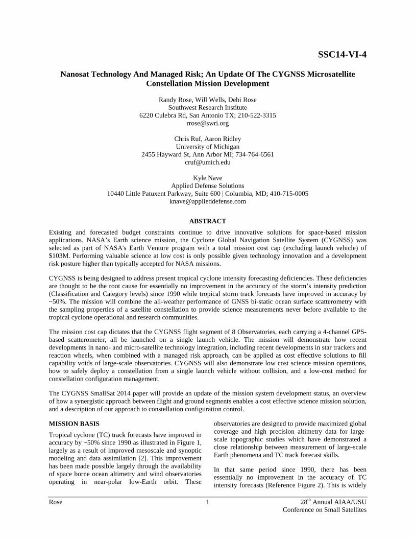
ABSTRACT Existing and forecasted budget constraints continue to drive innovative solutions for space-based mission applications. NASA’s Earth science mission, the Cyclone Global Navigation Satellite System (CYGNSS) was selected as part of NASA's Earth Venture program with a total mission cost cap (excluding launch vehicle) of $103M. Performing valuable science at low cost is only possible given technology innovation and a development risk posture higher than typically accepted for NASA missions.
CYGNSS is being designed to address present tropical cyclone intensity forecasting deficiencies. These deficiencies are thought to be the root cause for essentially no improvement in the accuracy of the storm’s intensity prediction (Classification and Category levels) since 1990 while tropical storm track forecasts have improved in accuracy by ~50%. The mission will combine the all-weather performance of GNSS bi-static ocean surface scatterometry with the sampling properties of a satellite constellation to provide science measurements never before available to the tropical cyclone operational and research communities.
The mission cost cap dictates that the CYGNSS flight segment of 8 Observatories, each carrying a 4-channel GPS-based scatterometer, all be launched on a single launch vehicle. The mission will demonstrate how recent developments in nano- and micro-satellite technology integration, including recent developments in star trackers and reaction wheels, when combined with a managed risk approach, can be applied as cost effective solutions to fill capability voids of large-scale observatories. CYGNSS will also demonstrate low cost science mission operations, how to safely deploy a constellation from a single launch vehicle without collision, and a low-cost method for constellation configuration management.
The CYGNSS SmallSat 2014 paper will provide an update of the mission system development status, an overview of how a synergistic approach between flight and ground segments enables a cost effective science mission solution, and a description of our approach to constellation configuration control.
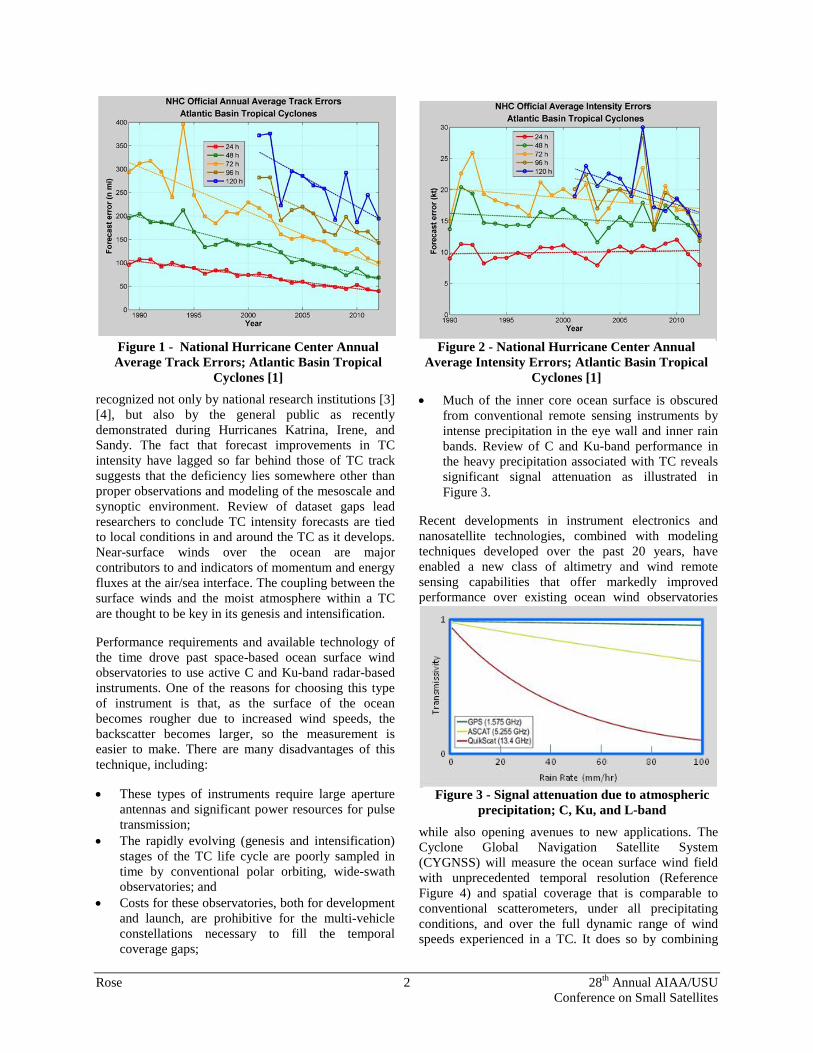
MISSION BASIS Tropical cyclone (TC) track forecasts have improved in accuracy by ~50% since 1990 as illustrated in Figure 1, largely as a result of improved mesoscale and synoptic modeling and data assimilation [2]. This improvement has been made possible largely through the availability of space borne ocean altimetry and wind observatories operating in near-polar low-Earth orbit. These
observatories are designed to provide maximized global coverage and high precision altimetry data for large-scale topographic studies which have demonstrated a close relationship between measurement of large-scale Earth phenomena and TC track forecast skills.
In that same period since 1990, there has been essentially no improvement in the accuracy of TC intensity forecasts (Reference Figure 2). This is widely
Rose 2 28th Annual AIAA/USU Conference on Small Satellites
recognized not only by national research institutions [3] [4], but also by the general public as recently demonstrated during Hurricanes Katrina, Irene, and Sandy. The fact that forecast improvements in TC intensity have lagged so far behind those of TC track suggests that the deficiency lies somewhere other than proper observations and modeling of the mesoscale and synoptic environment. Review of dataset gaps lead researchers to conclude TC intensity forecasts are tied to local conditions in and around the TC as it develops. Near-surface winds over the ocean are major contributors to and indicators of momentum and energy fluxes at the air/sea interface. The coupling between the surface winds and the moist atmosphere within a TC are thought to be key in its genesis and intensification.
Performance requirements and available technology of the time drove past space-based ocean surface wind observatories to use active C and Ku-band radar-based instruments. One of the reasons for choosing this type of instrument is that, as the surface of the ocean becomes rougher due to increased wind speeds, the backscatter becomes larger, so the measurement is easier to make. There are many disadvantages of this technique, including:
• These types of instruments require large aperture antennas and significant power resources for pulse transmission;
• The rapidly evolving (genesis and intensification) stages of the TC life cycle are poorly sampled in time by conventional polar orbiting, wide-swath observatories; and
• Costs for these observatories, both for development and launch, are prohibitive for the multi-vehicle constellations necessary to fill the temporal coverage gaps;
• Much of the inner core ocean surface is obscured from conventional remote sensing instruments by intense precipitation in the eye wall and inner rain bands. Review of C and Ku-band performance in the heavy precipitation associated with TC reveals significant signal attenuation as illustrated in Figure 3.
Recent developments in instrument electronics and nanosatellite technologies, combined with modeling techniques developed over the past 20 years, have enabled a new class of altimetry and wind remote sensing capabilities that offer markedly improved performance over existing ocean wind observatories
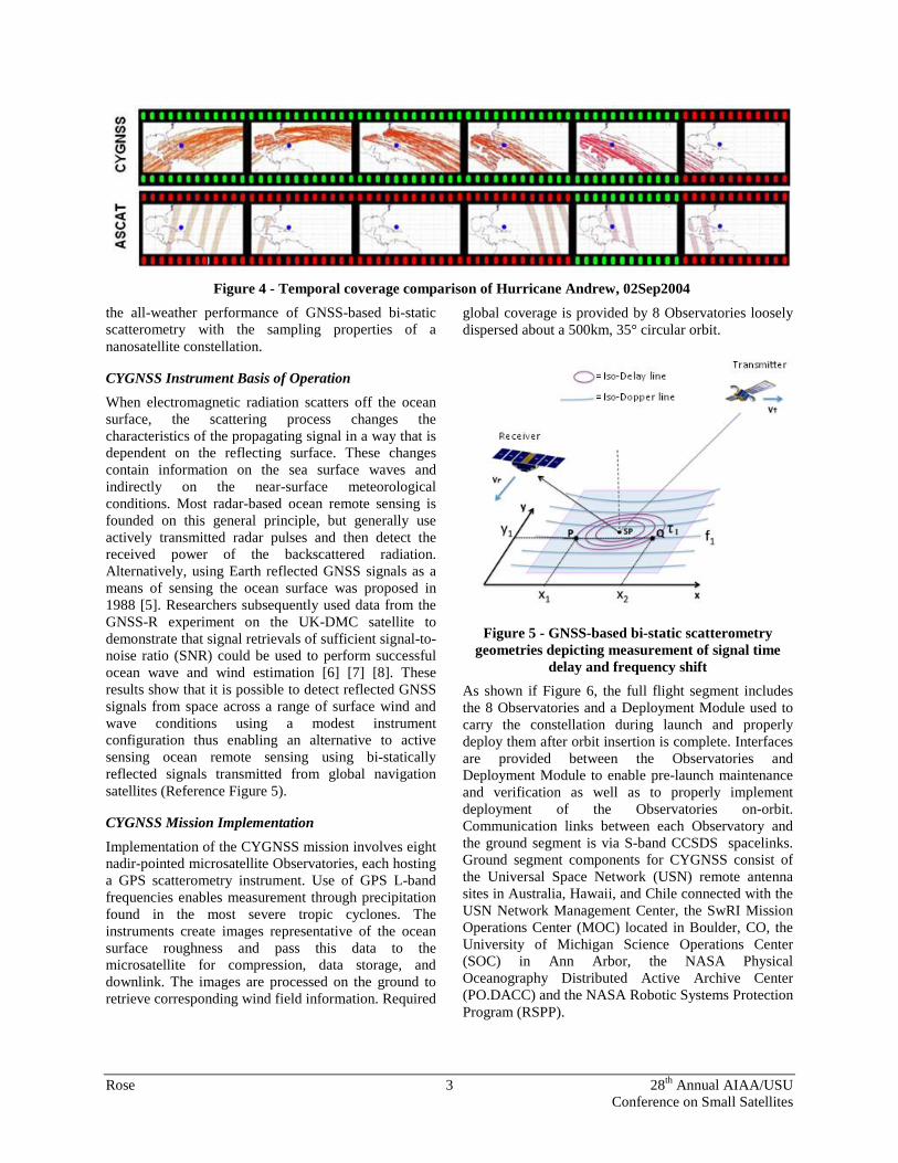
while also opening avenues to new applications. The Cyclone Global Navigation Satellite System (CYGNSS) will measure the ocean surface wind field with unprecedented temporal resolution (Reference Figure 4) and spatial coverage that is comparable to conventional scatterometers, under all precipitating conditions, and over the full dynamic range of wind speeds experienced in a TC. It does so by combining
Figure 1 - National Hurricane Center Annual Average Track Errors; Atlantic Basin Tropical
Cyclones [1]
Figure 2 - National Hurricane Center Annual Average Intensity Errors; Atlantic Basin Tropical
Cyclones [1]
Figure 3 - Signal attenuation due to atmospheric precipitation; C, Ku, and L-band
Rose 3 28th Annual AIAA/USU Conference on Small Satellites
the all-weather performance of GNSS-based bi-static scatterometry with the sampling properties of a nanosatellite constellation.
CYGNSS Instrument Basis of Operation When electromagnetic radiation scatters off the ocean surface, the scattering process changes the characteristics of the propagating signal in a way that is dependent on the reflecting surface. These changes contain information on the sea surface waves and indirectly on the near-surface meteorological conditions. Most radar-based ocean remote sensing is founded on this general principle, but generally use actively transmitted radar pulses and then detect the received power of the backscattered radiation. Alternatively, using Earth reflected GNSS signals as a means of sensing the ocean surface was proposed in 1988 [5]. Researchers subsequently used data from the GNSS-R experiment on the UK-DMC satellite to demonstrate that signal retrievals of sufficient signal-to-noise ratio (SNR) could be used to perform successful ocean wave and wind estimation [6] [7] [8]. These results show that it is possible to detect reflected GNSS signals from space across a range of surface wind and wave conditions using a modest instrument configuration thus enabling an alternative to active sensing ocean remote sensing using bi-statically reflected signals transmitted from global navigation satellites (Reference Figure 5).
CYGNSS Mission Implementation Implementation of the CYGNSS mission involves eight nadir-pointed microsatellite Observatories, each hosting a GPS scatterometry instrument. Use of GPS L-band frequencies enables measurement through precipitation found in the most severe tropic cyclones. The instruments create images representative of the ocean surface roughness and pass this data to the microsatellite for compression, data storage, and downlink. The images are processed on the ground to retrieve corresponding wind field information. Required
global coverage is provided by 8 Observatories loosely dispersed about a 500km, 35° circular orbit.
Figure 5 - GNSS-based bi-static scatterometry geometries depicting measurement of signal time
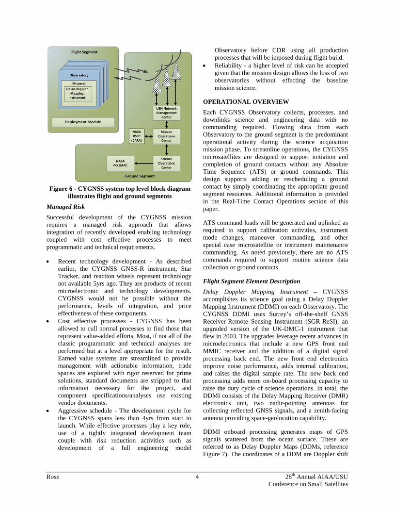
delay and frequency shift As shown if Figure 6, the full flight segment includes the 8 Observatories and a Deployment Module used to carry the constellation during launch and properly deploy them after orbit insertion is complete. Interfaces are provided between the Observatories and Deployment Module to enable pre-launch maintenance and verification as well as to properly implement deployment of the Observatories on-orbit. Communication links between each Observatory and the ground segment is via S-band CCSDS spacelinks. Ground segment components for CYGNSS consist of the Universal Space Network (USN) remote antenna sites in Australia, Hawaii, and Chile connected with the USN Network Management Center, the SwRI Mission Operations Center (MOC) located in Boulder, CO, the University of Michigan Science Operations Center (SOC) in Ann Arbor, the NASA Physical Oceanography Distributed Active Archive Center (PO.DACC) and the NASA Robotic Systems Protection Program (RSPP).
Figure 4 - Temporal coverage comparison of Hurricane Andrew, 02Sep2004
Rose 4 28th Annual AIAA/USU Conference on Small Satellites
Managed Risk Successful development of the CYGNSS mission requires a managed risk approach that allows integration of recently developed enabling technology coupled with cost effective processes to meet programmatic and technical requirements.
• Recent technology development - As described earlier, the CYGNSS GNSS-R instrument, Star Tracker, and reaction wheels represent technology not available 5yrs ago. They are products of recent microelectronic and technology developments. CYGNSS would not be possible without the performance, levels of integration, and price effectiveness of these components.
• Cost effective processes - CYGNSS has been allowed to cull normal processes to find those that represent value-added efforts. Most, if not all of the classic programmatic and technical analyses are performed but at a level appropriate for the result. Earned value systems are streamlined to provide management with actionable information, trade spaces are explored with rigor reserved for prime solutions, standard documents are stripped to that information necessary for the project, and component specifications/analyses use existing vendor documents.
• Aggressive schedule - The development cycle for the CYGNSS spans less than 4yrs from start to launch. While effective processes play a key role, use of a tightly integrated development team couple with risk reduction activities such as development of a full engineering model
Observatory before CDR using all production processes that will be imposed during flight build.
• Reliability - a higher level of risk can be accepted given that the mission design allows the loss of two observatories without effecting the baseline mission science.
OPERATIONAL OVERVIEW Each CYGNSS Observatory collects, processes, and downlinks science and engineering data with no commanding required. Flowing data from each Observatory to the ground segment is the predominant operational activity during the science acquisition mission phase. To streamline operations, the CYGNSS microsatellites are designed to support initiation and completion of ground contacts without any Absolute Time Sequence (ATS) or ground commands. This design supports adding or rescheduling a ground contact by simply coordinating the appropriate ground segment resources. Additional information is provided in the Real-Time Contact Operations section of this paper.
ATS command loads will be generated and uplinked as required to support calibration activities, instrument mode changes, maneuver commanding, and other special case microsatellite or instrument maintenance commanding. As noted previously, there are no ATS commands required to support routine science data collection or ground contacts.
Flight Segment Element Description Delay Doppler Mapping Instrument – CYGNSS accomplishes its science goal using a Delay Doppler Mapping Instrument (DDMI) on each Observatory. The CYGNSS DDMI uses Surrey’s off-the-shelf GNSS Receiver-Remote Sensing Instrument (SGR-ReSI), an upgraded version of the UK-DMC-1 instrument that flew in 2003. The upgrades leverage recent advances in microelectronics that include a new GPS front end MMIC receiver and the addition of a digital signal processing back end. The new front end electronics improve noise performance, adds internal calibration, and raises the digital sample rate. The new back end processing adds more on-board processing capacity to raise the duty cycle of science operations. In total, the DDMI consists of the Delay Mapping Receiver (DMR) electronics unit, two nadir-pointing antennas for collecting reflected GNSS signals, and a zenith-facing antenna providing space-geolocation capability.
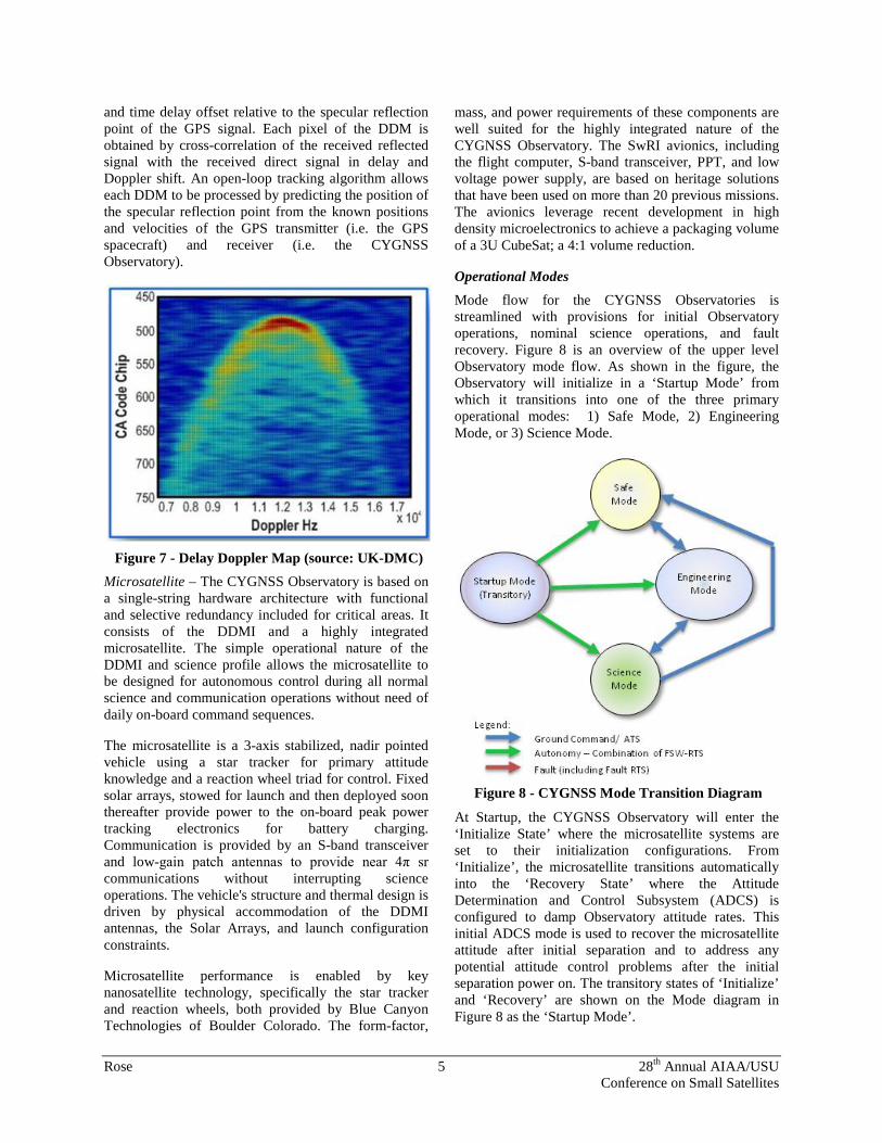
DDMI onboard processing generates maps of GPS signals scattered from the ocean surface. These are referred to as Delay Doppler Maps (DDMs, reference Figure 7). The coordinates of a DDM are Doppler shift
Figure 6 - CYGNSS system top level block diagram illustrates flight and ground segments
Rose 5 28th Annual AIAA/USU Conference on Small Satellites
and time delay offset relative to the specular reflection point of the GPS signal. Each pixel of the DDM is obtained by cross-correlation of the received reflected signal with the received direct signal in delay and Doppler shift. An open-loop tracking algorithm allows each DDM to be processed by predicting the position of the specular reflection point from the known positions and velocities of the GPS transmitter (i.e. the GPS spacecraft) and receiver (i.e. the CYGNSS Observatory).
Microsatellite – The CYGNSS Observatory is based on a single-string hardware architecture with functional and selective redundancy included for critical areas. It consists of the DDMI and a highly integrated microsatellite. The simple operational nature of the DDMI and science profile allows the microsatellite to be designed for autonomous control during all normal science and communication operations without need of daily on-board command sequences.
The microsatellite is a 3-axis stabilized, nadir pointed vehicle using a star tracker for primary attitude knowledge and a reaction wheel triad for control. Fixed solar arrays, stowed for launch and then deployed soon thereafter provide power to the on-board peak power tracking electronics for battery charging. Communication is provided by an S-band transceiver and low-gain patch antennas to provide near 4π sr communications without interrupting science operations. The vehicle's structure and thermal design is driven by physical accommodation of the DDMI antennas, the Solar Arrays, and launch configuration constraints.
Microsatellite performance is enabled by key nanosatellite technology, specifically the star tracker and reaction wheels, both provided by Blue Canyon Technologies of Boulder Colorado. The form-factor,
mass, and power requirements of these components are well suited for the highly integrated nature of the CYGNSS Observatory. The SwRI avionics, including the flight computer, S-band transceiver, PPT, and low voltage power supply, are based on heritage solutions that have been used on more than 20 previous missions. The avionics leverage recent development in high density microelectronics to achieve a packaging volume of a 3U CubeSat; a 4:1 volume reduction.
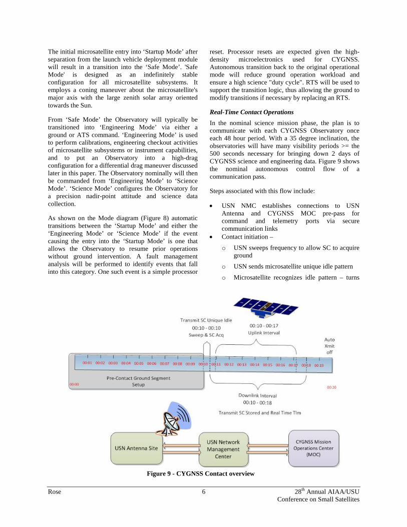
Operational Modes Mode flow for the CYGNSS Observatories is streamlined with provisions for initial Observatory operations, nominal science operations, and fault recovery. Figure 8 is an overview of the upper level Observatory mode flow. As shown in the figure, the Observatory will initialize in a ‘Startup Mode’ from which it transitions into one of the three primary operational modes: 1) Safe Mode, 2) Engineering Mode, or 3) Science Mode.
At Startup, the CYGNSS Observatory will enter the ‘Initialize State’ where the microsatellite systems are set to their initialization configurations. From ‘Initialize’, the microsatellite transitions automatically into the ‘Recovery State’ where the Attitude Determination and Control Subsystem (ADCS) is configured to damp Observatory attitude rates. This initial ADCS mode is used to recover the microsatellite attitude after initial separation and to address any potential attitude control problems after the initial separation power on. The transitory states of ‘Initialize’ and ‘Recovery’ are shown on the Mode diagram in Figure 8 as the ‘Startup Mode’.
Figure 7 - Delay Doppler Map (source: UK-DMC)
Figure 8 - CYGNSS Mode Transition Diagram
Rose 6 28th Annual AIAA/USU Conference on Small Satellites
The initial microsatellite entry into ‘Startup Mode’ after separation from the launch vehicle deployment module will result in a transition into the ‘Safe Mode’. 'Safe Mode' is designed as an indefinitely stable configuration for all microsatellite subsystems. It employs a coning maneuver about the microsatellite's major axis with the large zenith solar array oriented towards the Sun.
From ‘Safe Mode’ the Observatory will typically be transitioned into ‘Engineering Mode’ via either a ground or ATS command. ‘Engineering Mode’ is used to perform calibrations, engineering checkout activities of microsatellite subsystems or instrument capabilities, and to put an Observatory into a high-drag configuration for a differential drag maneuver discussed later in this paper. The Observatory nominally will then be commanded from ‘Engineering Mode’ to ‘Science Mode’. ‘Science Mode’ configures the Observatory for a precision nadir-point attitude and science data collection.
As shown on the Mode diagram (Figure 8) automatic transitions between the ‘Startup Mode’ and either the ‘Engineering Mode’ or ‘Science Mode’ if the event causing the entry into the ‘Startup Mode’ is one that allows the Observatory to resume prior operations without ground intervention. A fault management analysis will be performed to identify events that fall into this category. One such event is a simple processor
reset. Processor resets are expected given the high-density microelectronics used for CYGNSS. Autonomous transition back to the original operational mode will reduce ground operation workload and ensure a high science "duty cycle". RTS will be used to support the transition logic, thus allowing the ground to modify transitions if necessary by replacing an RTS.
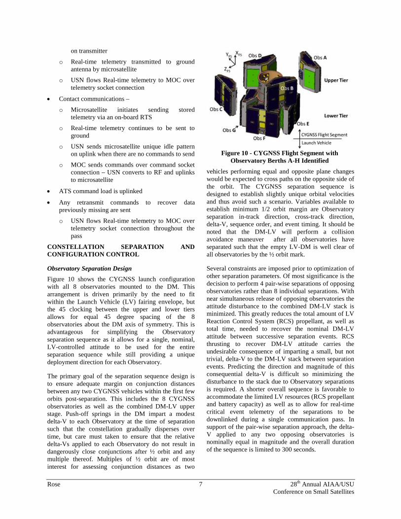
Real-Time Contact Operations In the nominal science mission phase, the plan is to communicate with each CYGNSS Observatory once each 48 hour period. With a 35 degree inclination, the observatories will have many visibility periods >= the 500 seconds necessary for bringing down 2 days of CYGNSS science and engineering data. Figure 9 shows the nominal autonomous control flow of a communication pass.
Steps associated with this flow include:
• USN NMC establishes connections to USN Antenna and CYGNSS MOC pre-pass for command and telemetry ports via secure communication links
• Contact initiation –
o USN sweeps frequency to allow SC to acquire ground
o USN sends microsatellite unique idle pattern
o Microsatellite recognizes idle pattern – turns
Figure 9 - CYGNSS Contact overview
Rose 7 28th Annual AIAA/USU Conference on Small Satellites
on transmitter
o Real-time telemetry transmitted to ground antenna by microsatellite
o USN flows Real-time telemetry to MOC over telemetry socket connection
• Contact communications –
o Microsatellite initiates sending stored telemetry via an on-board RTS
o Real-time telemetry continues to be sent to ground
o USN sends microsatellite unique idle pattern on uplink when there are no commands to send
o MOC sends commands over command socket connection – USN converts to RF and uplinks to microsatellite
• ATS command load is uplinked
• Any retransmit commands to recover data previously missing are sent
o USN flows Real-time telemetry to MOC over telemetry socket connection throughout the pass
CONSTELLATION SEPARATION AND CONFIGURATION CONTROL
Observatory Separation Design Figure 10 shows the CYGNSS launch configuration with all 8 observatories mounted to the DM. This arrangement is driven primarily by the need to fit within the Launch Vehicle (LV) fairing envelope, but the 45 clocking between the upper and lower tiers allows for equal 45 degree spacing of the 8 observatories about the DM axis of symmetry. This is advantageous for simplifying the Observatory separation sequence as it allows for a single, nominal, LV-controlled attitude to be used for the entire separation sequence while still providing a unique deployment direction for each Observatory.
The primary goal of the separation sequence design is to ensure adequate margin on conjunction distances between any two CYGNSS vehicles within the first few orbits post-separation. This includes the 8 CYGNSS observatories as well as the combined DM-LV upper stage. Push-off springs in the DM impart a modest delta-V to each Observatory at the time of separation such that the constellation gradually disperses over time, but care must taken to ensure that the relative delta-Vs applied to each Observatory do not result in dangerously close conjunctions after ½ orbit and any multiple thereof. Multiples of ½ orbit are of most interest for assessing conjunction distances as two
vehicles performing equal and opposite plane changes would be expected to cross paths on the opposite side of the orbit. The CYGNSS separation sequence is designed to establish slightly unique orbital velocities and thus avoid such a scenario. Variables available to establish minimum 1/2 orbit margin are Observatory separation in-track direction, cross-track direction, delta-V, sequence order, and event timing. It should be noted that the DM-LV will perform a collision avoidance maneuver after all observatories have separated such that the empty LV-DM is well clear of all observatories by the ½ orbit mark.
Several constraints are imposed prior to optimization of other separation parameters. Of most significance is the decision to perform 4 pair-wise separations of opposing observatories rather than 8 individual separations. With near simultaneous release of opposing observatories the attitude disturbance to the combined DM-LV stack is minimized. This greatly reduces the total amount of LV Reaction Control System (RCS) propellant, as well as total time, needed to recover the nominal DM-LV attitude between successive separation events. RCS thrusting to recover DM-LV attitude carries the undesirable consequence of imparting a small, but not trivial, delta-V to the DM-LV stack between separation events. Predicting the direction and magnitude of this consequential delta-V is difficult so minimizing the disturbance to the stack due to Observatory separations is required. A shorter overall sequence is favorable to accommodate the limited LV resources (RCS propellant and battery capacity) as well as to allow for real-time critical event telemetry of the separations to be downlinked during a single communication pass. In support of the pair-wise separation approach, the delta-V applied to any two opposing observatories is nominally equal in magnitude and the overall duration of the sequence is limited to 300 seconds.
Figure 10 - CYGNSS Flight Segment with Observatory Berths A-H Identified
Rose 8 28th Annual AIAA/USU Conference on Small Satellites
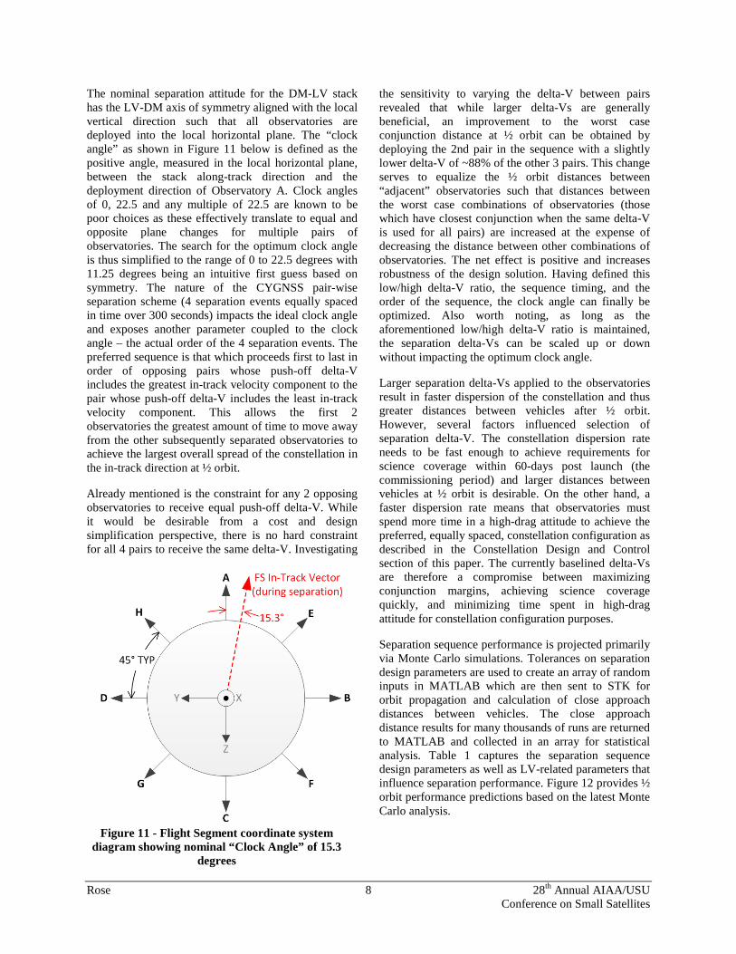
The nominal separation attitude for the DM-LV stack has the LV-DM axis of symmetry aligned with the local vertical direction such that all observatories are deployed into the local horizontal plane. The “clock angle” as shown in Figure 11 below is defined as the positive angle, measured in the local horizontal plane, between the stack along-track direction and the deployment direction of Observatory A. Clock angles of 0, 22.5 and any multiple of 22.5 are known to be poor choices as these effectively translate to equal and opposite plane changes for multiple pairs of observatories. The search for the optimum clock angle is thus simplified to the range of 0 to 22.5 degrees with 11.25 degrees being an intuitive first guess based on symmetry. The nature of the CYGNSS pair-wise separation scheme (4 separation events equally spaced in time over 300 seconds) impacts the ideal clock angle and exposes another parameter coupled to the clock angle – the actual order of the 4 separation events. The preferred sequence is that which proceeds first to last in order of opposing pairs whose push-off delta-V includes the greatest in-track velocity component to the pair whose push-off delta-V includes the least in-track velocity component. This allows the first 2 observatories the greatest amount of time to move away from the other subsequently separated observatories to achieve the largest overall spread of the constellation in the in-track direction at ½ orbit.
Already mentioned is the constraint for any 2 opposing observatories to receive equal push-off delta-V. While it would be desirable from a cost and design simplification perspective, there is no hard constraint for all 4 pairs to receive the same delta-V. Investigating
the sensitivity to varying the delta-V between pairs revealed that while larger delta-Vs are generally beneficial, an improvement to the worst case conjunction distance at ½ orbit can be obtained by deploying the 2nd pair in the sequence with a slightly lower delta-V of ~88% of the other 3 pairs. This change serves to equalize the ½ orbit distances between “adjacent” observatories such that distances between the worst case combinations of observatories (those which have closest conjunction when the same delta-V is used for all pairs) are increased at the expense of decreasing the distance between other combinations of observatories. The net effect is positive and increases robustness of the design solution. Having defined this low/high delta-V ratio, the sequence timing, and the order of the sequence, the clock angle can finally be optimized. Also worth noting, as long as the aforementioned low/high delta-V ratio is maintained, the separation delta-Vs can be scaled up or down without impacting the optimum clock angle.
Larger separation delta-Vs applied to the observatories result in faster dispersion of the constellation and thus greater distances between vehicles after ½ orbit. However, several factors influenced selection of separation delta-V. The constellation dispersion rate needs to be fast enough to achieve requirements for science coverage within 60-days post launch (the commissioning period) and larger distances between vehicles at ½ orbit is desirable. On the other hand, a faster dispersion rate means that observatories must spend more time in a high-drag attitude to achieve the preferred, equally spaced, constellation configuration as described in the Constellation Design and Control section of this paper. The currently baselined delta-Vs are therefore a compromise between maximizing conjunction margins, achieving science coverage quickly, and minimizing time spent in high-drag attitude for constellation configuration purposes.
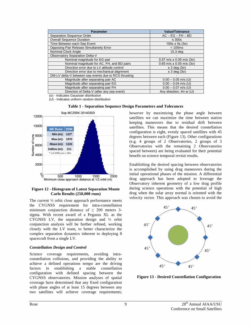
Separation sequence performance is projected primarily via Monte Carlo simulations. Tolerances on separation design parameters are used to create an array of random inputs in MATLAB which are then sent to STK for orbit propagation and calculation of close approach distances between vehicles. The close approach distance results for many thousands of runs are returned to MATLAB and collected in an array for statistical analysis. Table 1 captures the separation sequence design parameters as well as LV-related parameters that influence separation performance. Figure 12 provides ½ orbit performance predictions based on the latest Monte Carlo analysis.
Figure 11 - Flight Segment coordinate system diagram showing nominal “Clock Angle” of 15.3
degrees
Rose 9 28th Annual AIAA/USU Conference on Small Satellites
Figure 12 - Histogram of Latest Separation Monte Carlo Results (250,000 runs)
The current ½ orbit close approach performance meets the CYGNSS requirement for intra-constellation minimum conjunction distance of ≥ 200 meters 3-sigma. With recent award of a Pegasus XL as the CYGNSS LV, the separation design and ½ orbit conjunction analysis will be further refined, working closely with the LV team, to better characterize the complex separation dynamics inherent to deploying 8 spacecraft from a single LV.
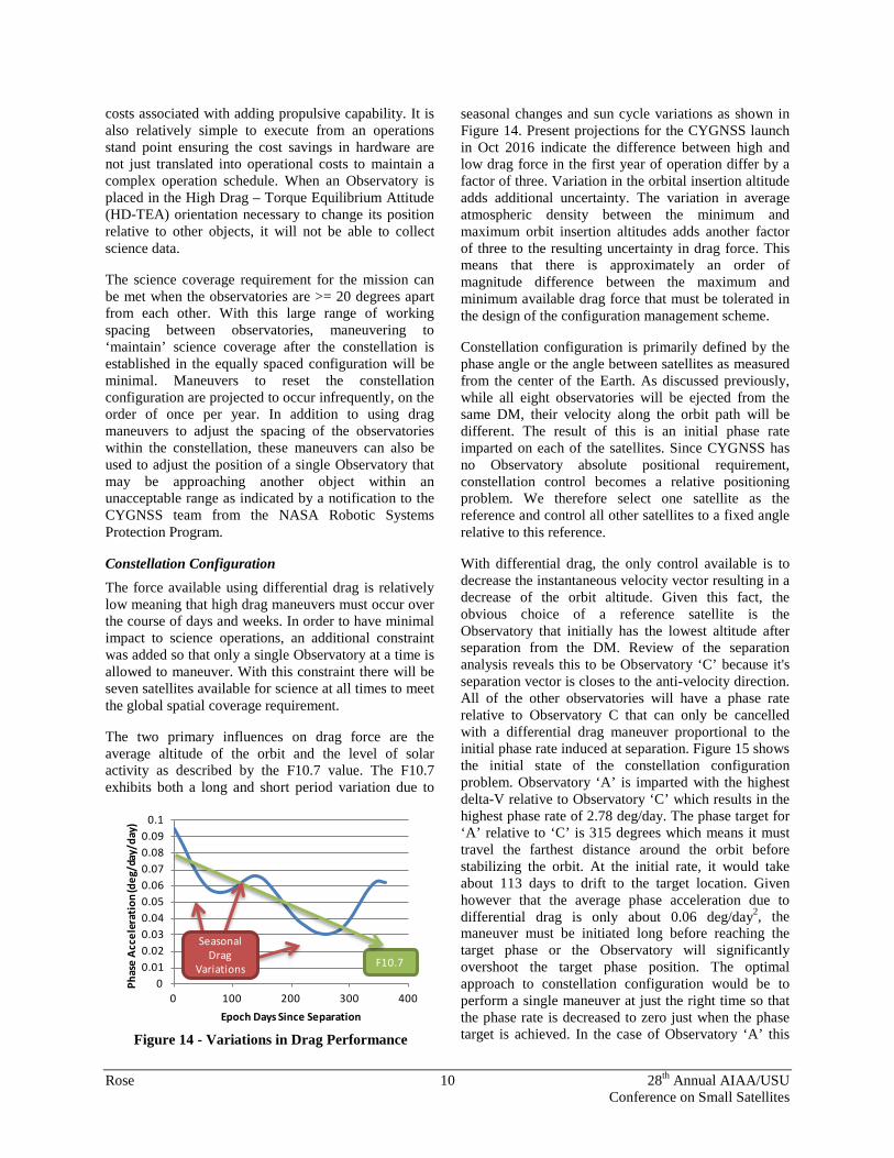
Constellation Design and Control Science coverage requirements, avoiding intra-constellation collisions, and providing the ability to achieve a defined operations tempo are the driving factors in establishing a stable constellation configuration with defined spacing between the CYGNSS observatories. Mission analyses of spatial coverage have determined that any fixed configuration with phase angles of at least 15 degrees between any two satellites will achieve coverage requirements;
however by maximizing the phase angle between satellites we can maximize the time between station keeping maneuvers due to residual drift between satellites. This means that the desired constellation configuration is eight, evenly spaced satellites with 45 degrees between each (Figure 13). Other configurations (e.g. 4 groups of 2 Observatories, 2 groups of 3 Observatories with the remaining 2 Observatories spaced between) are being evaluated for their potential benefit on science temporal revisit results.
Establishing the desired spacing between observatories is accomplished by using drag maneuvers during the initial operational phases of the mission. A differential drag approach has been adopted to leverage the Observatory inherent geometry of a low drag profile during science operations with the potential of high drag when the solar array normal is oriented with the velocity vector. This approach was chosen to avoid the
Parameter Value/Tolerance Separation Sequence Order AC – EG – FH – BD Overall Sequence Duration ≤ 300s Time Between each Sep Event 100s ± 5s (3σ) Opposing Pair Release Simultaneity Error < 100ms Nominal Clock Angle 15.3 deg Observatory Separation Delta-V -
Nominal magnitude for EG pair 0.57 m/s ± 0.05 m/s (3σ) Nominal magnitude for AC, FH, and BD pairs 0.65 m/s ± 0.05 m/s (3σ) Direction error due to LV attitude control ± 3 deg (3σ) Direction error due to mechanical alignment ± 3 deg (3σ)
DM-LV delta-V between sep events due to RCS thrusting - Magnitude after separating pair AC 0.00 – 0.05 m/s (U) Magnitude after separating pair EG 0.00 – 0.04 m/s (U) Magnitude after separating pair FH 0.00 – 0.07 m/s (U) Direction of Delta-V (after any sep event) Any direction, 4π sr (U)
(σ) - Indicates Gaussian distribution (U) - Indicates uniform random distribution
Table 1 - Separation Sequence Design Parameters and Tolerances
Figure 13 - Desired Constellation Configuration
Rose 10 28th Annual AIAA/USU Conference on Small Satellites
costs associated with adding propulsive capability. It is also relatively simple to execute from an operations stand point ensuring the cost savings in hardware are not just translated into operational costs to maintain a complex operation schedule. When an Observatory is placed in the High Drag – Torque Equilibrium Attitude (HD-TEA) orientation necessary to change its position relative to other objects, it will not be able to collect science data.
The science coverage requirement for the mission can be met when the observatories are >= 20 degrees apart from each other. With this large range of working spacing between observatories, maneuvering to ‘maintain’ science coverage after the constellation is established in the equally spaced configuration will be minimal. Maneuvers to reset the constellation configuration are projected to occur infrequently, on the order of once per year. In addition to using drag maneuvers to adjust the spacing of the observatories within the constellation, these maneuvers can also be used to adjust the position of a single Observatory that may be approaching another object within an unacceptable range as indicated by a notification to the CYGNSS team from the NASA Robotic Systems Protection Program.
Constellation Configuration The force available using differential drag is relatively low meaning that high drag maneuvers must occur over the course of days and weeks. In order to have minimal impact to science operations, an additional constraint was added so that only a single Observatory at a time is allowed to maneuver. With this constraint there will be seven satellites available for science at all times to meet the global spatial coverage requirement.
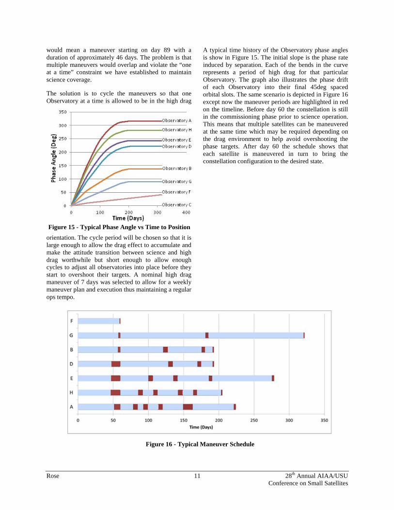
The two primary influences on drag force are the average altitude of the orbit and the level of solar activity as described by the F10.7 value. The F10.7 exhibits both a long and short period variation due to
seasonal changes and sun cycle variations as shown in Figure 14. Present projections for the CYGNSS launch in Oct 2016 indicate the difference between high and low drag force in the first year of operation differ by a factor of three. Variation in the orbital insertion altitude adds additional uncertainty. The variation in average atmospheric density between the minimum and maximum orbit insertion altitudes adds another factor of three to the resulting uncertainty in drag force. This means that there is approximately an order of magnitude difference between the maximum and minimum available drag force that must be tolerated in the design of the configuration management scheme.
Constellation configuration is primarily defined by the phase angle or the angle between satellites as measured from the center of the Earth. As discussed previously, while all eight observatories will be ejected from the same DM, their velocity along the orbit path will be different. The result of this is an initial phase rate imparted on each of the satellites. Since CYGNSS has no Observatory absolute positional requirement, constellation control becomes a relative positioning problem. We therefore select one satellite as the reference and control all other satellites to a fixed angle relative to this reference.
With differential drag, the only control available is to decrease the instantaneous velocity vector resulting in a decrease of the orbit altitude. Given this fact, the obvious choice of a reference satellite is the Observatory that initially has the lowest altitude after separation from the DM. Review of the separation analysis reveals this to be Observatory ‘C’ because it's separation vector is closes to the anti-velocity direction. All of the other observatories will have a phase rate relative to Observatory C that can only be cancelled with a differential drag maneuver proportional to the initial phase rate induced at separation. Figure 15 shows the initial state of the constellation configuration problem. Observatory ‘A’ is imparted with the highest delta-V relative to Observatory ‘C’ which results in the highest phase rate of 2.78 deg/day. The phase target for ‘A’ relative to ‘C’ is 315 degrees which means it must travel the farthest distance around the orbit before stabilizing the orbit. At the initial rate, it would take about 113 days to drift to the target location. Given however that the average phase acceleration due to differential drag is only about 0.06 deg/day2, the maneuver must be initiated long before reaching the target phase or the Observatory will significantly overshoot the target phase position. The optimal approach to constellation configuration would be to perform a single maneuver at just the right time so that the phase rate is decreased to zero just when the phase target is achieved. In the case of Observatory ‘A’ this
00.010.020.030.040.050.060.070.080.09
0.1
0 100 200 300 400
Phas
e A
ccel
erat
ion
(deg
/day
/day
)
Epoch Days Since Separation
F10.7
Seasonal Drag
Variations
Figure 14 - Variations in Drag Performance
Rose 11 28th Annual AIAA/USU Conference on Small Satellites
would mean a maneuver starting on day 89 with a duration of approximately 46 days. The problem is that multiple maneuvers would overlap and violate the “one at a time” constraint we have established to maintain science coverage.
The solution is to cycle the maneuvers so that one Observatory at a time is allowed to be in the high drag
orientation. The cycle period will be chosen so that it is large enough to allow the drag effect to accumulate and make the attitude transition between science and high drag worthwhile but short enough to allow enough cycles to adjust all observatories into place before they start to overshoot their targets. A nominal high drag maneuver of 7 days was selected to allow for a weekly maneuver plan and execution thus maintaining a regular ops tempo.
A typical time history of the Observatory phase angles is show in Figure 15. The initial slope is the phase rate induced by separation. Each of the bends in the curve represents a period of high drag for that particular Observatory. The graph also illustrates the phase drift of each Observatory into their final 45deg spaced orbital slots. The same scenario is depicted in Figure 16 except now the maneuver periods are highlighted in red on the timeline. Before day 60 the constellation is still in the commissioning phase prior to science operation. This means that multiple satellites can be maneuvered at the same time which may be required depending on the drag environment to help avoid overshooting the phase targets. After day 60 the schedule shows that each satellite is maneuvered in turn to bring the constellation configuration to the desired state.
Figure 15 - Typical Phase Angle vs Time to Position
Figure 16 - Typical Maneuver Schedule
Rose 12 28th Annual AIAA/USU Conference on Small Satellites
References 1. National Atmospheric and Oceanic
Administration National Hurricane Center, http://www.nhc.noaa.gov/verification/verify5.shtml
2. Atlas, R., et al., "Hurricane forecasting with the high-resolution NASA finite volume general circulation model," Geophysical Research Letters, vol. 3, p. 32, 2005.
3. US National Science Foundation, "Hurricane Warning: The critical need for a National Hurricane Research Initiative," NSF, NSB-06-115, 2007.
4. US National Oceanic and Atmospheric Administration, "Hurricane Forecast Improvement Project," NOAA, 2008.
5. Hall, el al., "Multistatic Scaterrometry," in Proceedings of the IEEE International Geoscience and Remote Sensing Symposium, Edinburgh, Scotland, 1988.
6. Gleason, S., et al., "Detection and Processing of Bi-Statically Reflected GPS Signals From Low Earth Orbit for the Purpose of Ocean Remote Sensing," IEEE Transactions on Geoscience and Remote Sensing, vol. 43, no. 5, 2005.
7. Gleason, S., "Remote Sensing Using Bistatic GNSS Reflections," in GNSS Applications and Methods, Artech House, ISBN-13 978-1-59693-329-3, 2009.
8. Clarizia, M. P., et al., “Spaceborne GNSS-R Minimum Variance Wind Speed Estimator,” IEEE Trans Geosci. Remote Sens., doi: 10.1109/TGRS.2014.2303831, 2014.