Embed Size (px)
Citation preview
Biomimetic nanoparticle synthesis
Nanoparticle Formation in Giant Vesicles: Synthesis inBiomimetic Compartments**
Peng Yang, Reinhard Lipowsky, and Rumiana Dimova*
The formation of inorganic nanomaterials such as CdS, ZnS,
and gold and silver nanoparticles was recently observed in
microorganisms.[1] The underlying processes are still not well
understood at the molecular scale. It has been proposed that
enzymes or peptides may take part in the nucleation and
reaction control.[2–4] It seems highly desirable to perform
similar reactions in artificial systems as a first step towards
biomimetic fabrication. Here, we introduce two novel protocols
for nanoparticle synthesis in such artificial systems provided by
giant vesicles. These membrane compartments have two main
advantages. First, individual compartments can be manipulated
by electric fields, micropipettes, or optical tweezers. Second,
the particle formation process can be directly monitored using
different microscopy techniques. Our protocols are based on
the controlled fusion of such vesicles and on their adhesion via
nanotubes. When these two protocols are applied to the
synthesis of CdS nanoparticles, the particle size can be tuned to
be 4 or 50 nm, which is in the range of quantum dot sizes. Our
results show that controlled changes in the structure and
topology of membrane compartments can be used to synthesize
nanoparticles even in the absence of inorganic binding
peptides.
Cells and microorganisms have been reported to have the
amazing ability to synthesize inorganic nanoparticles.[1] The
tentative interpretation of this observation is related to
the involvement of specific molecules[2,3] such as inorganic-
binding peptides,[3,4] which are also developed commercially to
control nanoparticle synthesis in artificial cell-free reaction
systems. In contrast to biochemistry-based cell-assisted synth-
esis, our present study aims at identifying mechanisms of
nanomaterial synthesis in confined compartments provided by
model biomembranes.
[�] Dr. R. Dimova, Dr. P. Yang,[+] Prof. R. Lipowsky
Department of Theory and Bio-Systems
Max Planck Institute of Colloids and Interfaces
Science Park Golm, 14424 Potsdam (Germany)
E-mail: [email protected]
[+] Current address: Department of Biomedical Engineering
Duke University
Durham, NC 27705, USA
[��] We would like to thank R. Knorr for his help with the confocalmicroscope. We acknowledge him and K. Tauer for critically read-ing the text.
: Supporting Information is available on the WWW under http://www.small-journal.com or from the author.
DOI: 10.1002/smll.200900560
small 2009, 5, No. 18, 2033–2037 � 2009 Wiley-VCH Verlag Gmb
Giant unilamellar vesicles (GUVs), having dimensions in
the cell-size scale (5–50mm), provide a suitable system,[5]
mimicking the confinement in cells or in the extracellular space.
Their lipid membrane is impermeable to ions and macro-
molecules, while water can freely permeate through the
membrane to assure osmotic balance. Thus, GUVs can be
used as tiny compartments closed for reacting species. In this
study, we take advantage of the small size of these compart-
ments having volumes in the picoliter range to perform
chemical synthesis. As an example, we considered the simple
reaction Na2SþCdCl2$CdSþ 2NaCl. When this reaction
occurs in bulk, even at weak millimolar concentrations,
irregular CdS sediments are formed because of the low
solubility product constant of CdS (Ksp¼ 10�27M
2 at 25 8C)
and the significant source of ions in the solution. In the confined
space of a giant vesicle, the source is quickly exhausted and
smaller particles can be formed. We consider the following
estimate: mixing 1 mM solutions of Na2S and CdS in a vesicle
with radius 10mm can give yield to a CdS crystal not larger than
270� 270� 270 nm3 if all ions take part in building it (here we
assumed that the distance between the participating Cd atoms
corresponds to an approximately 2 A lattice spacing). In the
event of mixing these two solutions, however, not one but many
smaller particles may be nucleated and formed. The strategy of
our experiments was to prepare vesicles containing either
CdCl2 or Na2S and trigger the reaction either by vesicle fusion
or by slow exchange and gradual mixing of the encapsulated
solutions.
Up to now, nanoparticles have only been synthesized in
lipid vesicles in the size range 30–80 nm (see, for example,
References [6,7]), where the particle size would usually be
determined by the vesicle volume. The vesicles were employed
mainly to provide an initially closed container for the reaction.
The attention was addressed towards the final reaction product,
but no care was taken for preserving the membrane state and
integrity during and after reaction completion. In contrast to
nanometer-sized vesicles, using giant vesicles as microreactors
allows for direct microscopy observation of the state of the
membrane. Thus, this is the first time to induce, control, and
directly observe particle formation in an artificial cell system
whereby the membrane container remains intact. In addition,
our study extends confined vesicular reactions to micrometer-
scale cell-size reactors for the synthesis of nanomaterials.
Finally, differently from the experimental conditions used
previously for the synthesis of nanoparticles, here we employ
processes mimicking intracellular mixing or membrane fusion,
which naturally occur in cells.
H & Co. KGaA, Weinheim 2033
communications
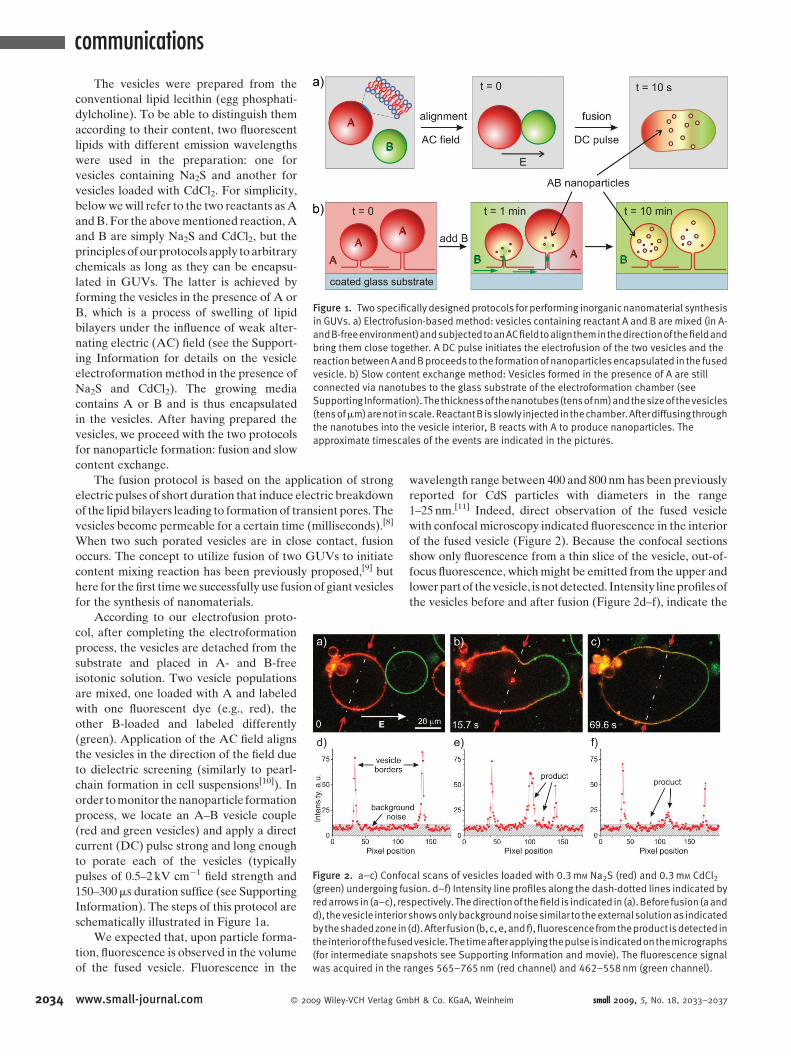
Figure 1. Two specifically designedprotocols for performing inorganic nanomaterial synthesis
in GUVs. a) Electrofusion-based method: vesicles containing reactant A and B are mixed (in A-
andB-freeenvironment)andsubjectedtoanACfieldtoaligntheminthedirectionofthefieldand
bring them close together. A DC pulse initiates the electrofusion of the two vesicles and the
reactionbetweenAandBproceeds to the formationof nanoparticles encapsulated in the fused
vesicle. b) Slow content exchange method: Vesicles formed in the presence of A are still
connected via nanotubes to the glass substrate of the electroformation chamber (see
Supporting Information).Thethicknessof thenanotubes(tensofnm)andthesizeof thevesicles
(tensofmm)arenot inscale.ReactantB isslowly injected in thechamber.Afterdiffusingthrough
the nanotubes into the vesicle interior, B reacts with A to produce nanoparticles. The
approximate timescales of the events are indicated in the pictures.
2034
The vesicles were prepared from the
conventional lipid lecithin (egg phosphati-
dylcholine). To be able to distinguish them
according to their content, two fluorescent
lipids with different emission wavelengths
were used in the preparation: one for
vesicles containing Na2S and another for
vesicles loaded with CdCl2. For simplicity,
below we will refer to the two reactants as A
and B. For the above mentioned reaction, A
and B are simply Na2S and CdCl2, but the
principles of our protocols apply to arbitrary
chemicals as long as they can be encapsu-
lated in GUVs. The latter is achieved by
forming the vesicles in the presence of A or
B, which is a process of swelling of lipid
bilayers under the influence of weak alter-
nating electric (AC) field (see the Support-
ing Information for details on the vesicle
electroformation method in the presence of
Na2S and CdCl2). The growing media
contains A or B and is thus encapsulated
in the vesicles. After having prepared the
vesicles, we proceed with the two protocols
for nanoparticle formation: fusion and slow
content exchange.
The fusion protocol is based on the application of strong
electric pulses of short duration that induce electric breakdown
of the lipid bilayers leading to formation of transient pores. The
vesicles become permeable for a certain time (milliseconds).[8]
When two such porated vesicles are in close contact, fusion
occurs. The concept to utilize fusion of two GUVs to initiate
content mixing reaction has been previously proposed,[9] but
here for the first time we successfully use fusion of giant vesicles
for the synthesis of nanomaterials.
Figure 2. a–c) Confocal scans of vesicles loaded with 0.3mM Na2S (red) and 0.3mM CdCl2(green) undergoing fusion. d–f) Intensity line profiles along the dash-dotted lines indicated by
redarrows in (a–c), respectively. Thedirectionof thefield is indicated in (a).Before fusion(aand
d), thevesicle interior showsonlybackgroundnoisesimilar to theexternalsolutionas indicated
bytheshadedzonein(d).After fusion(b,c,e,andf),fluorescencefromtheproduct isdetectedin
theinteriorof thefusedvesicle.Thetimeafterapplyingthepulseis indicatedonthemicrographs
(for intermediate snapshots see Supporting Information and movie). The fluorescence signal
was acquired in the ranges 565–765nm (red channel) and 462–558nm (green channel).
According to our electrofusion proto-
col, after completing the electroformation
process, the vesicles are detached from the
substrate and placed in A- and B-free
isotonic solution. Two vesicle populations
are mixed, one loaded with A and labeled
with one fluorescent dye (e.g., red), the
other B-loaded and labeled differently
(green). Application of the AC field aligns
the vesicles in the direction of the field due
to dielectric screening (similarly to pearl-
chain formation in cell suspensions[10]). In
order to monitor the nanoparticle formation
process, we locate an A–B vesicle couple
(red and green vesicles) and apply a direct
current (DC) pulse strong and long enough
to porate each of the vesicles (typically
pulses of 0.5–2 kV cm�1 field strength and
150–300ms duration suffice (see Supporting
Information). The steps of this protocol are
schematically illustrated in Figure 1a.
We expected that, upon particle forma-
tion, fluorescence is observed in the volume
of the fused vesicle. Fluorescence in the
www.small-journal.com � 2009 Wiley-VCH Verlag Gm
wavelength range between 400 and 800 nm has been previously
reported for CdS particles with diameters in the range
1–25 nm.[11] Indeed, direct observation of the fused vesicle
with confocal microscopy indicated fluorescence in the interior
of the fused vesicle (Figure 2). Because the confocal sections
show only fluorescence from a thin slice of the vesicle, out-of-
focus fluorescence, which might be emitted from the upper and
lower part of the vesicle, is not detected. Intensity line profiles of
the vesicles before and after fusion (Figure 2d–f), indicate the
bH & Co. KGaA, Weinheim small 2009, 5, No. 18, 2033–2037
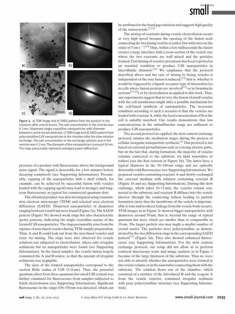
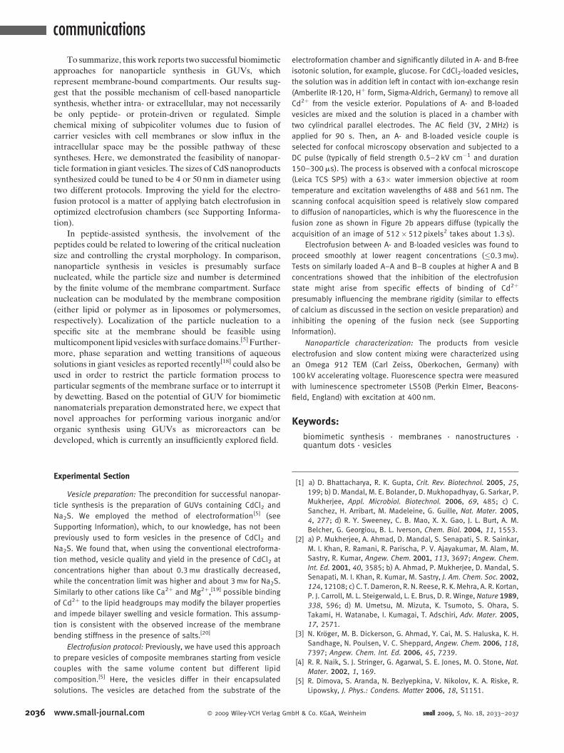
Figure 3. a) TEM image and b) SAED pattern from the product in the
solutions after vesicle fusion. The salt concentration in the vesicles was
0.3mM. Dispersed single-crystalline nanoparticles with diameter
between4and8nmaredetected. c) TEM imageandd)SAEDpattern from
polycrystalline CdS nanopraticles in the chamber after the slow solution
exchange. The salt concentration in the exchange solution and in the
vesicles was 0.3mM. The diameter of the nanoparticles is around 50nm.
The rings presumably represent averaged power diffraction.
presence of a product with fluorescence above the background
noise signal. The signal is detectable for a few minutes before
decaying completely (see Supporting Information). Presum-
ably, capping of the nanoparticles with a shell (which, for
example, can be achieved by successful fusion with vesicles
loaded with the capping agent) may lead to stronger and long-
term fluorescence as typical for commercial quantum dots.
The obtained product was also investigated using transmis-
sion electron microscopy (TEM) and selected area electron
diffraction (SAED). Dispersed nanoparticles of diameters
ranging between 4 and 8 nm were found (Figure 3a). The SAED
pattern (Figure 3b) showed weak rings but also characteristic
spotty patterns, indicating the single crystalline nature of the
formed CdS nanoparticles. The rings presumably arise from the
rupture of non-fused vesicles during TEM sample preparation.
Thus, A and B could leak out from the non-fused vesicles and
react via mixing. The rings were also observed for vesicle
solutions not subjected to electrofusion, where only irregular
sediments but no nanoparticles were found (see Supporting
Information). In the fused samples, the vesicle fusion largely
consumed the A and B source, so that the amount of irregular
sediments was negligible.
The sizes of the formed nanoparticles correspond to the
exciton Bohr radius of CdS (5–6 nm). Thus, the potential
quantum effect from these quantum dot-sized CdS crystals was
further examined for fluorescence from samples subjected to
batch electrofusion (see Supporting Information). Significant
fluorescence in the range 430–530 nm was detected, which can
small 2009, 5, No. 18, 2033–2037 � 2009 Wiley-VCH Verlag Gmb
be attributed to the band gap emission and suggests high quality
of the nanocrystals.[7,12]
The mixing of reactants during vesicle electrofusion occurs
at very high speed because the opening of the fusion neck
connecting the two fusing vesicles is rather fast with rates on the
order of 5 cm s�1.[13] Thus, within a few milliseconds the fusion
creates a large interface with a cross section of the vesicle size
where the two reactants are well mixed and the particles
formed. Fast mixing of reactive precursors has been reported as
an essential condition to produce CdS nanoparticles in
microfluidic channels.[14] We emphasize that the protocol
described above and the rate of mixing in fusing vesicles is
independent of the way fusion is induced,[13] that is, whether it
would be triggered by a ligand–receptor type of interaction (as
in cells where fusion proteins are involved[15] or in biomimetic
systems[13,16]) or by electrofusion as applied in this work. Thus,
our experiments suggest that in vivo, the fusion of small vesicles
with the cell membranes might infer a possible mechanism for
the cell-based synthesis of nanoparticles. The necessary
condition according to such a scenario is that the vesicles are
loaded with reactant A, while the local concentration of B at the
cell is suitably matched. Our results demonstrate that low
concentrations in the submillimolar range are sufficient to
produce CdS nanoparticles.
The second protocol we applied, the slow content exchange
protocol, mimics the incubation stages during the process of
cellular inorganic nanoparticle synthesis.[1] This protocol is not
based on external perturbations such as a strong electric pulse,
but on the fact that, during formation, the majority of vesicles
remains connected to the substrate via lipid nanotubes or
tethers (see the first cartoon in Figure 1b). The latter have a
typical diameter in the 50–100 nm range and are optically
detectable with fluorescence (see Supporting Information). We
prepared vesicles containing reactant A and slowly exchanged
the external medium with solution containing reactant B
(Figure 1b and see Supporting Information). During this slow
exchange, which takes 10–15 min, the vesicles remain con-
nected to the substrate and reactant B diffuses into the vesicle
interior through the connecting tethers leading to particle
formation (note that the membrane of the vesicle is imperme-
able to ions and no direct leakage from the vesicle body occurs).
TEM images as in Figure 3c showed bigger nanoparticles with
diameters around 50 nm, that is, beyond the range of typical
quantum dot sizes, which are smaller than or comparable to
10 nm. The larger particle size may imply a smaller number of
crystal nuclei. The particles were polycrystalline as demon-
strated by the two diffraction rings in the corresponding SAED
pattern[17] (Figure 3d). They also showed enhanced fluores-
cence (see Supporting Information). For the slow content
exchange protocol, our setup did not allow us to perform
confocal microscopy scans and image analysis as in Figure 2
because of the large thickness of the substrate. Thus we were
not able to identify whether the nanoparticles were formed in
the vesicle volume or in the nanotubes connecting them with the
substrate. The solution flown out of the chamber, which
consisted of a mixture of the introduced B and the reagent A
from the vesicle exterior, contained irregular sediment
with poor polycrystalline structure (see Supporting Informa-
tion).
H & Co. KGaA, Weinheim www.small-journal.com 2035
communications
2036
To summarize, this work reports two successful biomimetic
approaches for nanoparticle synthesis in GUVs, which
represent membrane-bound compartments. Our results sug-
gest that the possible mechanism of cell-based nanoparticle
synthesis, whether intra- or extracellular, may not necessarily
be only peptide- or protein-driven or regulated. Simple
chemical mixing of subpicoliter volumes due to fusion of
carrier vesicles with cell membranes or slow influx in the
intracellular space may be the possible pathway of these
syntheses. Here, we demonstrated the feasibility of nanopar-
ticle formation in giant vesicles. The sizes of CdS nanoproducts
synthesized could be tuned to be 4 or 50 nm in diameter using
two different protocols. Improving the yield for the electro-
fusion protocol is a matter of applying batch electrofusion in
optimized electrofusion chambers (see Supporting Informa-
tion).
In peptide-assisted synthesis, the involvement of the
peptides could be related to lowering of the critical nucleation
size and controlling the crystal morphology. In comparison,
nanoparticle synthesis in vesicles is presumably surface
nucleated, while the particle size and number is determined
by the finite volume of the membrane compartment. Surface
nucleation can be modulated by the membrane composition
(either lipid or polymer as in liposomes or polymersomes,
respectively). Localization of the particle nucleation to a
specific site at the membrane should be feasible using
multicomponent lipid vesicles with surface domains.[5] Further-
more, phase separation and wetting transitions of aqueous
solutions in giant vesicles as reported recently[18] could also be
used in order to restrict the particle formation process to
particular segments of the membrane surface or to interrupt it
by dewetting. Based on the potential of GUV for biomimetic
nanomaterials preparation demonstrated here, we expect that
novel approaches for performing various inorganic and/or
organic synthesis using GUVs as microreactors can be
developed, which is currently an insufficiently explored field.
Experimental Section
Vesicle preparation: The precondition for successful nanopar-
ticle synthesis is the preparation of GUVs containing CdCl2 and
Na2S. We employed the method of electroformation[5] (see
Supporting Information), which, to our knowledge, has not been
previously used to form vesicles in the presence of CdCl2 and
Na2S. We found that, when using the conventional electroforma-
tion method, vesicle quality and yield in the presence of CdCl2 at
concentrations higher than about 0.3mM drastically decreased,
while the concentration limit was higher and about 3mM for Na2S.
Similarly to other cations like Ca2þ and Mg2þ,[19] possible binding
of Cd2þ to the lipid headgroups may modify the bilayer properties
and impede bilayer swelling and vesicle formation. This assump-
tion is consistent with the observed increase of the membrane
bending stiffness in the presence of salts.[20]
Electrofusion protocol: Previously, we have used this approach
to prepare vesicles of composite membranes starting from vesicle
couples with the same volume content but different lipid
composition.[5] Here, the vesicles differ in their encapsulated
solutions. The vesicles are detached from the substrate of the
www.small-journal.com � 2009 Wiley-VCH Verlag Gm
electroformation chamber and significantly diluted in A- and B-free
isotonic solution, for example, glucose. For CdCl2-loaded vesicles,
the solution was in addition left in contact with ion-exchange resin
(Amberlite IR-120, Hþ form, Sigma-Aldrich, Germany) to remove all
Cd2þ from the vesicle exterior. Populations of A- and B-loaded
vesicles are mixed and the solution is placed in a chamber with
two cylindrical parallel electrodes. The AC field (3V, 2MHz) is
applied for 90 s. Then, an A- and B-loaded vesicle couple is
selected for confocal microscopy observation and subjected to a
DC pulse (typically of field strength 0.5–2 kV cm�1 and duration
150–300ms). The process is observed with a confocal microscope
(Leica TCS SP5) with a 63� water immersion objective at room
temperature and excitation wavelengths of 488 and 561 nm. The
scanning confocal acquisition speed is relatively slow compared
to diffusion of nanoparticles, which is why the fluorescence in the
fusion zone as shown in Figure 2b appears diffuse (typically the
acquisition of an image of 512�512pixels2 takes about 1.3 s).
Electrofusion between A- and B-loaded vesicles was found to
proceed smoothly at lower reagent concentrations (�0.3mM).
Tests on similarly loaded A–A and B–B couples at higher A and B
concentrations showed that the inhibition of the electrofusion
state might arise from specific effects of binding of Cd2þ
presumably influencing the membrane rigidity (similar to effects
of calcium as discussed in the section on vesicle preparation) and
inhibiting the opening of the fusion neck (see Supporting
Information).
Nanoparticle characterization: The products from vesicle
electrofusion and slow content mixing were characterized using
an Omega 912 TEM (Carl Zeiss, Oberkochen, Germany) with
100 kV accelerating voltage. Fluorescence spectra were measured
with luminescence spectrometer LS50B (Perkin Elmer, Beacons-
field, England) with excitation at 400 nm.
Keywords:
biomimetic synthesis . membranes . nanostructures .quantum dots . vesicles
[1] a) D. Bhattacharya, R. K. Gupta, Crit. Rev. Biotechnol. 2005, 25,199; b) D. Mandal, M. E. Bolander, D. Mukhopadhyay, G. Sarkar, P.
Mukherjee, Appl. Microbiol. Biotechnol. 2006, 69, 485; c) C.
Sanchez, H. Arribart, M. Madeleine, G. Guille, Nat. Mater. 2005,4, 277; d) R. Y. Sweeney, C. B. Mao, X. X. Gao, J. L. Burt, A. M.
Belcher, G. Georgiou, B. L. Iverson, Chem. Biol. 2004, 11, 1553.[2] a) P. Mukherjee, A. Ahmad, D. Mandal, S. Senapati, S. R. Sainkar,
M. I. Khan, R. Ramani, R. Parischa, P. V. Ajayakumar, M. Alam, M.
Sastry, R. Kumar, Angew. Chem. 2001, 113, 3697; Angew. Chem.
Int. Ed. 2001, 40, 3585; b) A. Ahmad, P. Mukherjee, D. Mandal, S.
Senapati, M. I. Khan, R. Kumar, M. Sastry, J. Am. Chem. Soc. 2002,124, 12108; c) C. T. Dameron, R. N. Reese, R. K. Mehra, A. R. Kortan,
P. J. Carroll, M. L. Steigerwald, L. E. Brus, D. R. Winge, Nature 1989,338, 596; d) M. Umetsu, M. Mizuta, K. Tsumoto, S. Ohara, S.
Takami, H. Watanabe, I. Kumagai, T. Adschiri, Adv. Mater. 2005,17, 2571.
[3] N. Kroger, M. B. Dickerson, G. Ahmad, Y. Cai, M. S. Haluska, K. H.
Sandhage, N. Poulsen, V. C. Sheppard, Angew. Chem. 2006, 118,7397; Angew. Chem. Int. Ed. 2006, 45, 7239.
[4] R. R. Naik, S. J. Stringer, G. Agarwal, S. E. Jones, M. O. Stone, Nat.
Mater. 2002, 1, 169.[5] R. Dimova, S. Aranda, N. Bezlyepkina, V. Nikolov, K. A. Riske, R.
Lipowsky, J. Phys.: Condens. Matter 2006, 18, S1151.
bH & Co. KGaA, Weinheim small 2009, 5, No. 18, 2033–2037
[6] a) S. Mann, J. P. Hannington, R. J. P. Williams, Nature 1986, 324,565; b) S. Bhandarkar, A. Bose, J. Colloid Interface Sci. 1990, 139,541.
[7] a) M. I. Khramov, V. N. Parmon, J. Photochem. Photobiol. A 1993,71, 279; b) B. A. Korgel, H. G. Monbouquette, Langmuir 2000, 16,3588.
[8] K. A. Riske, R. Dimova, Biophys. J. 2005, 88, 1143.[9] a) D. T. Chiu, C. F. Wilson, F. Ryttsen, A. Stromberg, C. Farre, A.
Karlsson, S. Nordholm, A. Gaggar, B. P. Modi, A. Moscho, R. A.
Garza-Lopez, O. Orwar, R. N. Zare, Science 1999, 283, 1892; b) S.Kulin, R. Kishore, K. Helmerson, L. Locascio, Langmuir 2003, 19,8206.
[10] U. Zimmermann, Rev. Physiol. Biochem. Pharmacol. 1986, 105,176.
[11] H. Weller, Angew. Chem. 1993, 105, 43; Angew. Chem. Int. Ed.
1993, 32, 41.[12] J. A. Gratt, R. E. Cohen, J. Appl. Polym. Sci. 2003, 88, 177.
small 2009, 5, No. 18, 2033–2037 � 2009 Wiley-VCH Verlag Gmb
[13] C. K. Haluska, K. A. Riske, V. Marchi-Artzner, J. M. Lehn, R.
Lipowsky, R. Dimova, Proc. Natl. Acad. Sci. USA 2006, 103, 15841.[14] I. Shestopalov, J. D. Tice, R. F. Ismagilov, Lab Chip 2004, 4, 316.[15] R. Jahn, T. Lang, T. C. Sudhof, Cell 2003, 112, 519.[16] A. Richard, V. Marchi-Artzner, M. N. Lalloz, M. J. Brienne, F. Artzner,
T. Gulik-Krzywicki, M. A. Guedeau-Boudeville, J. M. Lehn, Proc.
Natl. Acad. Sci. USA 2004, 101, 15279.[17] S. Gorer, J. A. Ganske, J. C. Hemminger, R. M. Penner, J. Am. Chem.
Soc. 1998, 120, 9584.[18] Y. Li, R. Lipowsky, R. Dimova, J. Am. Chem. Soc. 2008, 130, 12252.[19] a) R. A. Bockmann, H. Grubmuller, Angew. Chem. 2004, 116, 1039;
Angew. Chem. Int. Ed. 2004, 43, 1021; b) C. Sinn, M. Antonietti, R.
Dimova, Colloids Surf. A 2006, 283, 410.[20] G. Pabst, A. Hodzic, J. Strancar, S. Danner, M. Rappolt, P. Laggner,
Biophys. J. 2007, 93, 2688.
H & Co. KGaA, Weinheim
Received: April 1, 2009Published online: June 8, 2009
www.small-journal.com 2037