Embed Size (px)
Citation preview
Nanomodification of Cement Based Materials
Surendra ShahWalter P. Murphy Professor (Emeritus)
Center for Advanced Cement-Based MaterialsNorthwestern University
Evanston, IL 60306, USA
Anna Maria Workshop XIIIUnconventional Concrete, November 7-9

2
Contributing researchers
Prof. Paramita Mondal, University of Illinois at Urbana-Champaign Prof. Raissa Ferron, University of Texas at Austin Zoi Metaxa, Northwestern University and Democritus University Prof. Maria Konsta-Gdoutos, Democritus University of Thrace Dr. Nathan Tregger, Northwestern University Dr. Jae Hong Kim, Northwestern University Mark Beacraft, Lehigh University Dr. John Gaitero, Labein Tecnalia Dr. Amedeo Gregori, University of L’Aquila Prof. Kejin Wang, Iowa State University Jean-Juste Mbele, Schlumberger Dr. Thomas Voigt, USG Prof. Xiaoyan Liu, Hohai University Shiho Kawashima, Northwestern University Pengkun Hou, Chongqing University

3
An example of nanomodification
Mother of pearl (99% CaCO3) has flexural strength of 100 MPa – an order of magnitude higher than chalk
Structure of mother of pearl

4
Types of nanoparticles
Nanoclay
Limestone nanoparticles
Nanosilica
Titanium dioxide nanoparticles
Nanofibers: Carbon nanotubes (CNTs)
Can nanoparticles enhance properties and performance through nanomodification?

5
Outline
Nanoclays in Flocculation Study
NanoCaCO3 in HVFA Cement Systems
Nanosilica
Photocatalytic Cement-Based Materials
Carbon Nanotubes as Reinforcement and Sensors

6
Self-consolidating concrete (SCC)
Highly flowable concrete that resists segregation and develops its mechanical properties without vibration
→Take advantage of the high consolida ng proper esAntonio Vernon - Wikipedia
Trump Tower, Chicago(Courtesy: Tregger)
QuickTime™ and aCinepak decompressor
are needed to see this picture.

7
SCC and Formwork Pressure
Mock Up Test (2007, Dante Galeota, and et al.)
Research in collaboration with Université de Sherbrooke and CTL

Current Situation
ACI 347: presumed lateral pressure should equal the hydrostatic pressure until the effect of formwork pressure isunderstood
Studies have shown that SCC can have pressure less than hydrostatic1-3 due to structural rebuilding
1. A. Assaad, et. al, Cement and Concrete Research, v.35, 2005
2. P. Billberg, et. al, Concrete International, v.27 (10), 2005
3. Y. Vanhove, et.al, Magazine of Concrete Research, vol. 56, 2004.

9
10 μm
Effect of dispersion on ActiGel
• During mixing, particles break up into much smaller needle structures Mbele
500 nm

10
Simulation Range: Real scale column heights from~3 m to 20 m, and any casting rates
Formwork pressure simulation
D
H
Pressure Sensors(capacity: 50psi = 344kPa)
Lab formworkD = 15 cmH = 30 cm
11
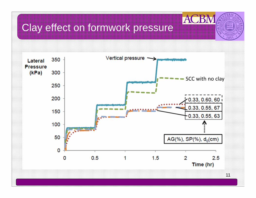
Clay effect on formwork pressure
SCC with no clay

12
Quantitative measure of clay effect
Methods of investigation:
Shear rheology
Compressive rheology
Floc size determination
Tack test
Filtration test

13
Focus Beam Reflectance Measurement (FBRM):Gives information about Floc size indirect indication of flocculation
- in situ/in-line information about the evolution and size of particle
- scans highly focused laser beam across suspension and measure time duration of back scattered light
Time taken for beam to scan is measure of particle size
Focus beam cross particle on a straight line between any 2 points.
Hundreds of thousands of chords are measured per second
Chord length range: 0.5 –1000 μm
FBRM: A Way to Measure Floc Size
(Mettler-Toledo, 2005)

14
T im e (se c )
0 1 0 0 0 2 0 0 0 3 0 0 0 4 0 0 0 5 0 0 0 6 0 0 0
Mea
n Ch
ord
Leng
th (
μ m)
1 0 .0
1 0 .5
1 1 .0
1 1 .5
1 2 .0
1 2 .5
1 3 .0
1 3 .5
P 2P 2 -V M AP 2 -M e taP 2 -S e p io
Stage 1: 40rpm
Stage 2: 400rpm
Stage 3: 40rpm
Stage 4: 400rpm
P2 : Plain PasteP2-VMA: Paste with a cellulose-based viscosity-modifying agent P2-Meta: Paste with metakaolinite clay (calcined, purified kaolinite)P2-Sepio: Paste mix with sepiolite clay (hydrated magnesium silicate serpentine)
Floc size evolution

15
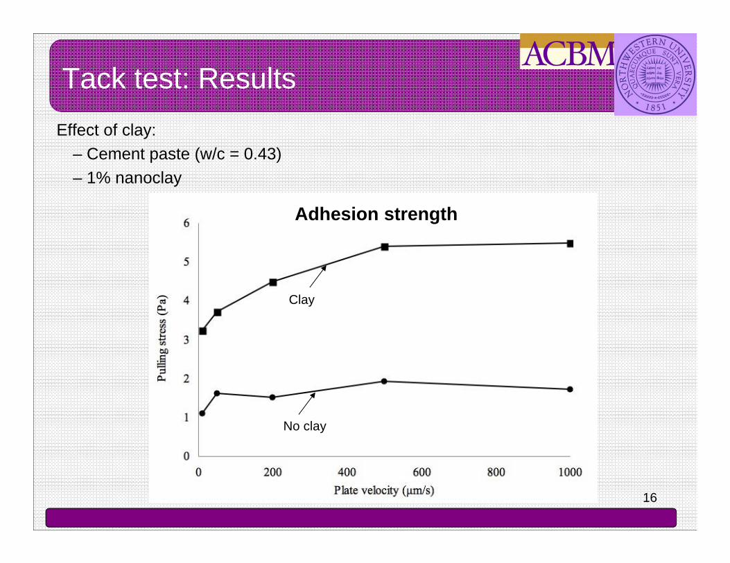
• Properties measured by tack test include:– Adhesion strength
• Flow resistance and intrinsic cohesion (internal strength) at rest– Cohesion strength
• Static property relating to intermolecular and capillary forces
Kaci et al. 2010
Extension
Shear
Tack test
16
Effect of clay:– Cement paste (w/c = 0.43) – 1% nanoclay
Clay
No clay
Adhesion strength
Tack test: Results

17
Outline
Nanoclays in Flocculation Study
NanoCaCO3 in HVFA Cement Systems
Nanosilica
Photocatalytic Cement-Based Materials
Carbon Nanotubes as Reinforcement and Sensors

18
HVFA cementitious materials: Eco-friendly
Advantages: High flowability Low cement content Low hydration heat Strength gain in the later age Improvement in durability Low costs
Disadvantages: Low early age strength gain
Nanoparticles in high-volume fly ash (HVFA) cement systems
Aerial image of Kingston Ash Slide 12/23/08

19
NanoCaCO3 on HVFA system
Microparticles
Sato and Beaudoin 2011
Effect of size50% fly ash cement paste10, 20% addition of micro- vs nanoparticles
Rate of hydration
Nanoparticles
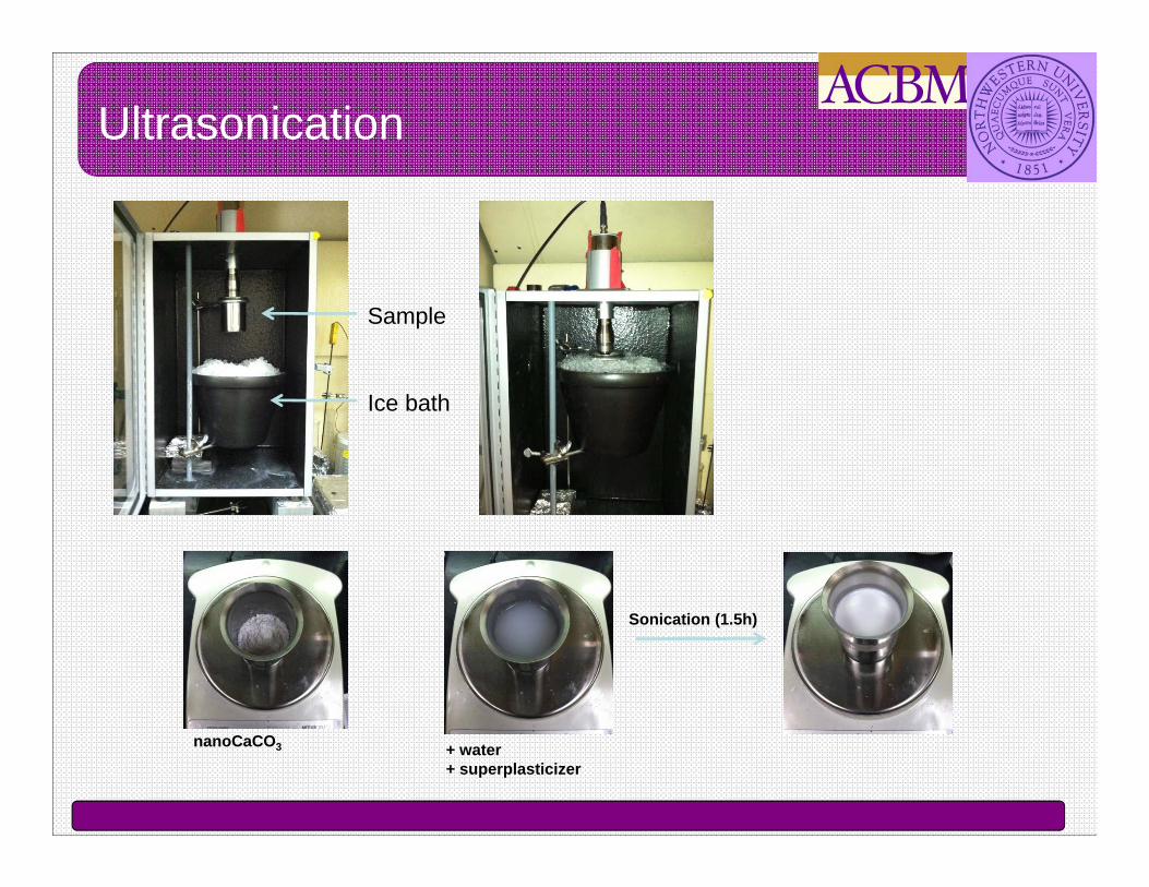
Ultrasonication
Sample
Ice bath
nanoCaCO3 + water+ superplasticizer
Sonication (1.5h)
21
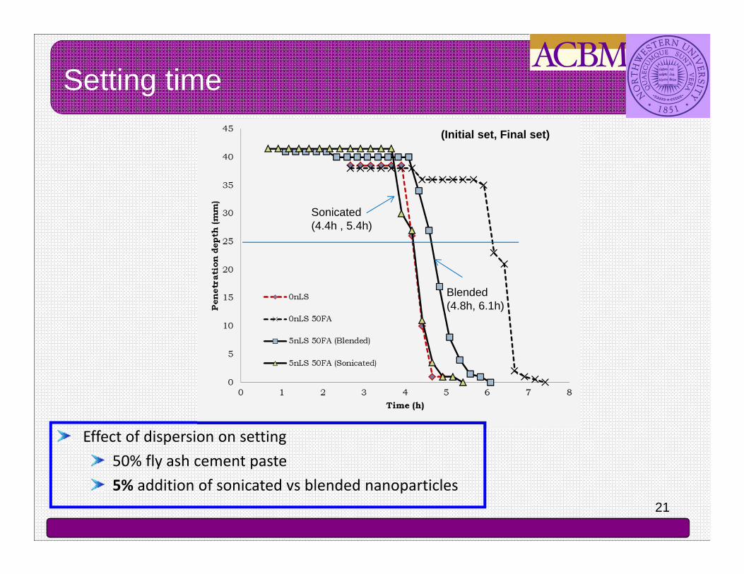
Setting time
Effect of dispersion on setting 50% fly ash cement paste5% addition of sonicated vs blended nanoparticles
Sonicated(4.4h , 5.4h)
Blended(4.8h, 6.1h)
(Initial set, Final set)

Rate of hydration
Effect of dispersionCement paste (w/c = 0.4)5% addition of sonicated vs blended nanoparticles

Early-age compressive strength gain
Sonicated
Blended
Plain cement paste
Plain 30% fly ash cement paste
Effect of dispersion30% fly ash cement paste (w/c = 0.43)5% addition of sonicated vs blended nanoparticles

24
Outline
Nanoclays in Flocculation Study
NanoCaCO3 in HVFA Cement Systems
Nanosilica
Photocatalytic Cement-Based Materials
Carbon Nanotubes as Reinforcement and Sensors

Degradation
Results of Compression Test
Cement paste ref. sample
Sample with 6% nanosilica
Sample with 6% micro-silica
Unidad Asociada
NANOC ®
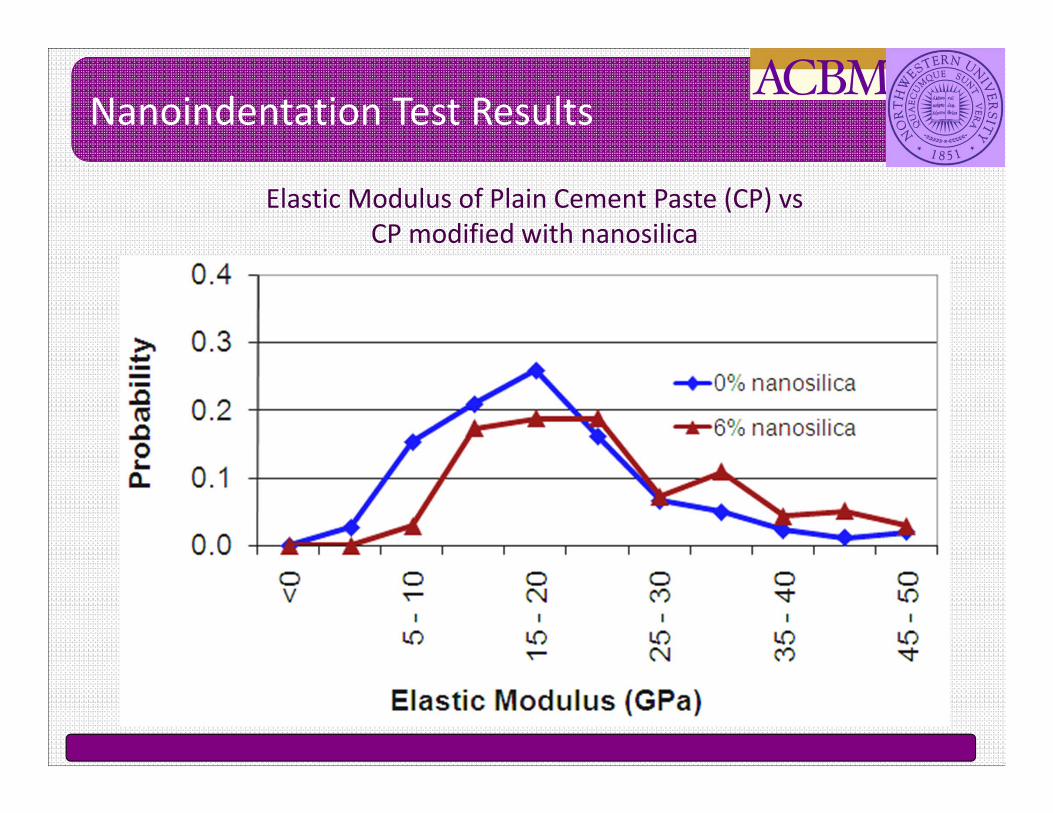
Elastic Modulus of Plain Cement Paste (CP) vs CP modified with nanosilica
Nanoindentation Test Results

Calcium Leaching Study of Cement Pastes Modified with Nanosilica
• Nanosilica fill up the gaps in cement paste microstructure and provide denser microstructure• Reduce the impact of calcium leaching on cement paste.
Unidad Asociada
NANOC ®
“Silica Nanoparticle Addition to Control the Calcium-Leaching in Cement-Based Materials,” J. J. Gaitero*, Y. Sáez de Ibarra, E. Erkizia, and I. Campillo; Physica Status Solidi (a) 203, No. 6, 1313-1318 (2006)

28
Traditional Electrochemical Chloride Extraction
EN Treatment
Capillary Pore
Reinforcement
Capillary Pore
Reinforcement
: Chloride Ion : Chloride Ion: Nanoparticle
Kupwade Patil. K, Gordon. K, Xu. K, Moral O, Cardenas. H and Lee. L .Corrosion mitigation in concrete beams using electrokinetic nanoparticle treatment,. Excellence in Concrete Construction through Innovation, September 2008, London, UK, pp.365-371.
Electrokinetic Nanoparticle (EN) Treatment to Extend Reinforcement Service Life

29
Pozzolanic Nanoparticle
24 nm
Silica particle core
2nm Alumino Particles(Source of positive charge)

3030
Bridge Deck Specimens
Kupwade Patil, K and Cardenas H, .Corrosion mitigation in concrete using electrokinetic injection of reactive composite nanoparticles,.Proc. 53rd International SAMPEsymposium, May 2008, Long Beach, CA.
Unprotected: Severely Cracked
Nanoparticle Protected
After a year of Salt Testing
ASTM G109 Beams Under Long-term Testing Simulating Bridge Deck Laden with Road Salt

31
Outline
Nanoclays in Flocculation Study
NanoCaCO3 in HVFA Cement Systems
Nanosilica
Photocatalytic Cement-Based Materials
Carbon Nanotubes as Reinforcement and Sensors
32
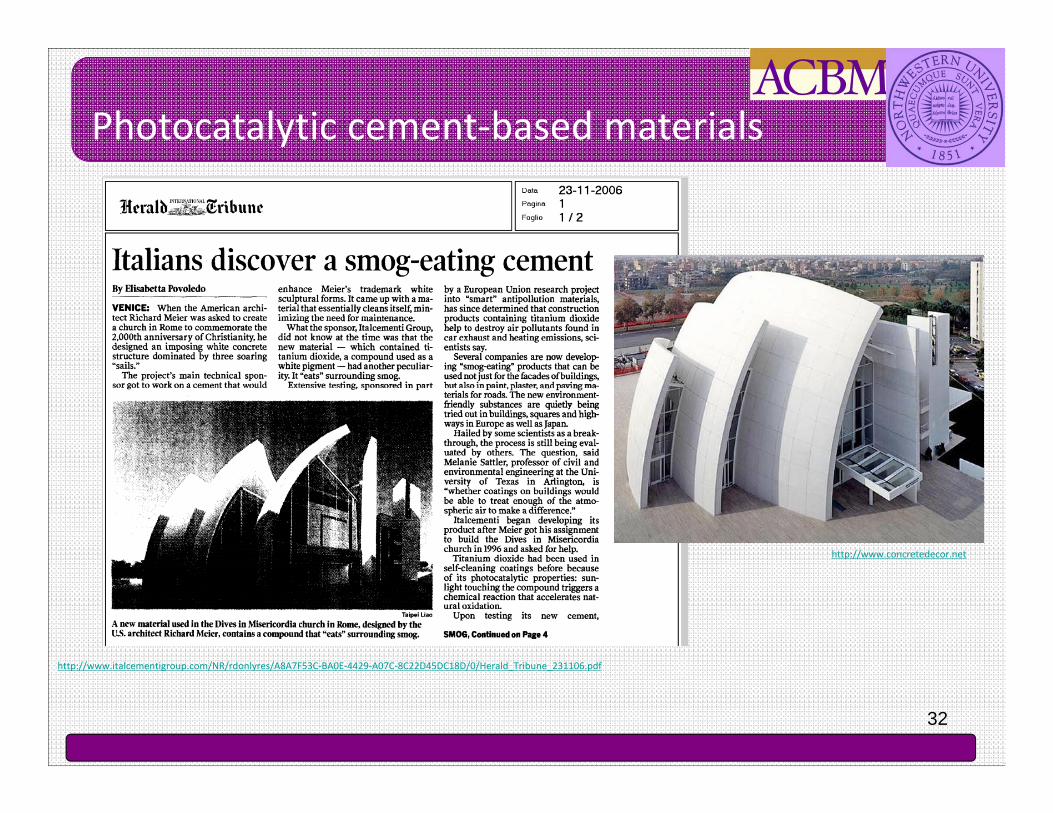
Photocatalytic cement-based materials
http://www.italcementigroup.com/NR/rdonlyres/A8A7F53C-BA0E-4429-A07C-8C22D45DC18D/0/Herald_Tribune_231106.pdf
http://www.concretedecor.net

33
http://www.concretedecor.net
Self-cleaning (Lotus effect)
Photocatalytic concrete unit pavers (Japan)
Air-cleaning
Self-disinfecting
Number of viable E.Coli cells
After radiation
Before
Dadjour et al. 2005
Photocatalytic cement-based materials

34
Rate of hydration reaction of ordinary Portland cement and TiO2 blended cements
TiO2 nanoparticles
Lee et al., 2009Jayapalan et al., 2009

35
Outline
Nanoclays in Flocculation Study
NanoCaCO3 in HVFA Cement Systems
Nanomechanical Properties for Construction Materials
Electrokinetic Nanoparticle (EN) Treatment for Corrosion Mitigation
Photocatalytic Cement-Based Materials
Carbon Nanotubes as Reinforcement and Sensors

36
1nm
MWCNT
• A CNT is a sheet of graphite rolled up into a tube structure and can be described as:– Single walled (SWNT)
• A single sheet has been rolled up with diameter close to 1nm
– Multi walled (MWNT)• A number of sheets have been rolled up with diameter
ranges from 10-80nm
SWCNT
10-8
0 nm
Carbon Nanotubes (CNTs)

37
CNTs Dispersion-Main Challenge
• CNTs tent to adhere together due to Van der Waal forces
500 nm 500 nm
SEM images of poorly dispersed CNTs forming bundles in 18h cement paste

38
Goal – Effective Dispersion of MWCNTs in Aqueous Surfactant Solution:
•Ultrasonic energy by sonication
•Surface treatment with commercially available surfactant
ACBM Dispersion Method
QuickTime™ and aYUV420 codec decompressor
are needed to see this picture.

39
Highly Dispersed MWCNTs
MWCNT Bundled=120nm
Dispersion with Sonication+Surfactant
Without Dispersion
Individual MWCNT d=30nm
500 nm
• Effective Dispersion of MWCNTs Requires Ultrasonic Energy and the Use of Surfactant (SFC)
500 nm
Konsta-Gdoutos et al, Cement and Concrete Composites, 2010Konsta-Gdoutos et al, Cement and Concrete Research, 2010
MWCNT Bundle

40
0
0.1
0.2
0.3
0.4
0 -5
5 -1
0
10 -
15
15 -
20
20 -
25
25 -
30
30 -
35
35 -
40
40 -
45
45 -
50
Prob
abili
ty
Young's Modulus (GPa)
CP w/c=0.5CP+0.08wt% Short MWCNTs
High Stif fness C-S-H
CH (Ca(OH)2)Porous Phase
Low Stif fness C-S-H
Elastic Modulus of Plain Cement Paste (CP) vs CP reinforced with MWCNTs
Nanoindentation Test Results
Elastic Modulus (GPa)Shah et al, NICOM3, Springer, 2009
41
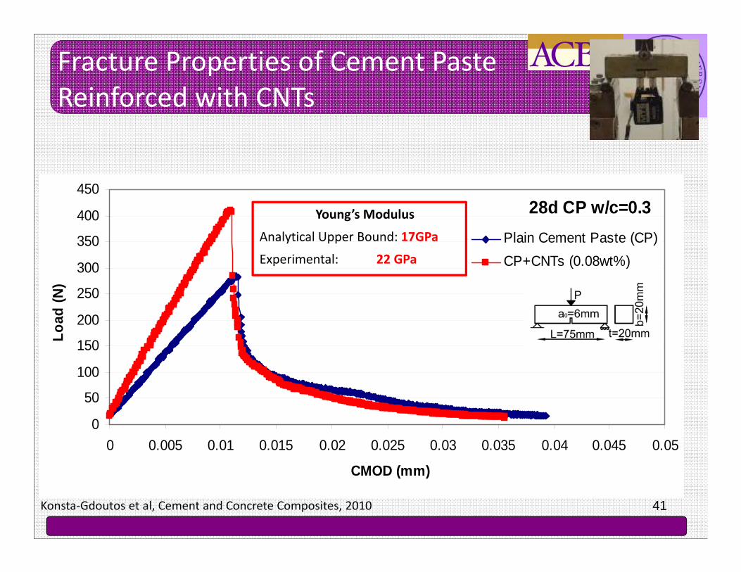
28d CP w/c=0.3
0
50
100
150
200
250
300
350
400
450
0 0.005 0.01 0.015 0.02 0.025 0.03 0.035 0.04 0.045 0.05
CMOD (mm)
Load
(N)
Plain Cement Paste (CP)CP+CNTs (0.08wt%)
Fracture Properties of Cement Paste Reinforced with CNTs
Konsta-Gdoutos et al, Cement and Concrete Composites, 2010
Young’s Modulus
Analytical Upper Bound: 17GPa
Experimental: 22 GPa
42
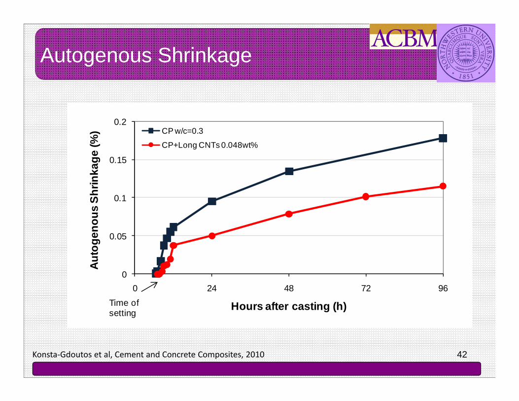
Autogenous Shrinkage
0
0.05
0.1
0.15
0.2
0 24 48 72 96
Auto
geno
us S
hrin
kage
(%)
Hours after casting (h)
CP w/c=0.3
CP+Long CNTs 0.048wt%
Time of setting
Konsta-Gdoutos et al, Cement and Concrete Composites, 2010
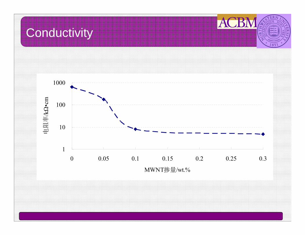
Conductivity
1
10
100
1000
0 0.05 0.1 0.15 0.2 0.25 0.3
MWNT掺量/wt.%
电阻率/kΩ•cm

Development of “smart” cement based materials using CNTsGoal: Develop stress and strain sensing materials used for structural health monitoring
How?: Using Carbon nanotubes
• CNTs exhibit electromechanical properties. When subject to stress their electrical properties change analogous to the stress level indicating a linear and reversible piezoresistive response
Compressive stress and electrical resistance of cement composite with 0.1wt% MWCNTsHan et al., Nanotechnology, 2009

45
Outline
Nanoclays in Flocculation Study
NanoCaCO3 in HVFA Cement Systems
Nanomechanical Properties for Construction Materials
Electrokinetic Nanoparticle (EN) Treatment for Corrosion Mitigation
Photocatalytic Cement-Based Materials
Carbon Nanotubes as Reinforcement and Sensors

Conclusion
Nanoparticles:Nanoclay
NanoCaCO3
NanosilicaNanoTiO2
CNTs
Potential benefit to properties:Rheology
Hydration kineticsMechanical
C-S-H modificationDurabilityShrinkage
PhotocatalysisConductivity
Piezoresistivity
Nanomodification

47
Tina Fineberg, NY Times
• Damascus sabers contain carbon nanotubes, as well as nanoscale wires of cementite, giving them a moiré pattern (from Nov. 28 article in NY Times, photo taken by Tina Fineberg)
• Nanotubes over 400 years old!
New (Old?) Materials!
TEM image showing nanotubes[Reibold et. al, 2006]

48
Thank you!