Embed Size (px)
Citation preview

Namco/System1 4in1 Kit INSTALL GUIDE
The Namco/System1 4 in1 kit installed in the picture above. There are 7 PWB’s that come with the kit.
1. Voice/Game Controller PWB 2. CHR Rom PWB 3. CHR8 Rom PWB 4. OBJ Rom PWB 5. SND Rom PWB 6. PRG Rom PWB 7. EEP Rom PWB

Also included in the kit are: A ribbon cable with 6 pin connectors that connect the PWB’s together & 2 pin header.
Three 3pin connectors with wires attached (brown/red/orange).

A reset cable with 4pin/3pin connector and attached wires.
Some of the tools that may be needed for the install are pictured below.

IMPORTANT INFORMATION PLEASE READ AND UNDERSTAND FULLY You will nee to remove all Roms from the PCB as listed. VOICE0 thru VOICE4 CHR0 thru CHR8 OBJ0 thru 0BJ7 SOUND0 thru SOUND1 CUSTOM PRG0 thru PRG7 Depending on which System 1 board you have there could be a mix of EPROMS and masked ROMS in the above locations. Usually the masked ROMs will have the ROM type (OBJ0….OBJ7, etc) printed on the chip. And ususally the EPROMS have labels, BUT it is a good idea to mark the chips location BEFORE removing them. Just in case you ever wanted to uninstall the kit. IMPORTANT: YOU MUST MAKE SURE THAT JP3 IN THE CORNER OF THE PCB HAS THE JUMPER SET TO (F) AS SHOWN BELOW. DO THIS NOW BEFORE PROCEEDING ANY FURTHER OR YOU WILL DAMAGE TO YOUR PCB WHEN THE KIT IS INSTALLED AND POWERED UP.

After the chips are removed the next step is to install the 2 pin header in the location That is marked RESET on the silkscreen as shown below. You will need to remove the solder from the holes with solder-wik or a desoldering tool.
Solder the 2 pin header in the orientation as shown in the picture below.

Now flip the board over and take the reset cable with the 2 bare wires (red/orange) and solder the wires to the pads as shown below.
Now flip the PCB back over and install the 3 pin connector into the header.

Next install the Voice/Game controller PWB as shown below.
Then attach 4 pin connector from reset cable as shown below.

Now install the longest of the three 3 pin connectors with cables. Locate the IC (N8 )74F138 (next to socket CHR7) and solder the wires as follows PIN1 – BROWN PIN2 – RED PIN3 - ORANGE
Plug in CHR Rom PWB into location CHR2.

Now attach other end of 3 pin cable to connector as shown below.
Plug in CHR8 Rom PWB into location CHR8.

Now install the middle length of the 2 remaining 3 pin connectors with cables. Locate the IC (T9 )74LS138 (to thr right of socket CHR8) and solder the wires as follows PIN1 – BROWN PIN2 – RED PIN3 – ORANGE
Plug in OBJ Rom PWB into location OBJ7.
Now attach other end of 3 pin cable to connector as shown below
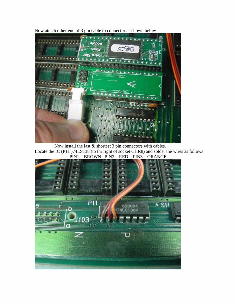
Now install the last & shortest 3 pin connectors with cables. Locate the IC (P11 )74LS138 (to thr right of socket CHR8) and solder the wires as follows PIN1 – BROWN PIN2 – RED PIN3 – ORANGE

Plug in PRG Rom PWB into location PRG1.
Now attach other end of 3 pin cable to connector as shown below.

Next install the SND PWB into location as shown below.
Your board should now look like the one in the picture below.

Now flip the board over and remove the EEPROM at location U1 as shown below.
Now install EEP Rom PWB as shown.

Ok, now get the 6pin ribbon cable with multiple connectors, and starting with the 2 connectors that are furtherest apart from the end of the cable, plug the end connector into the EEP Rom PWB as shown.
Flip the board over and install the next connector into the Voice/Game control PWB.

Next the CHR Rom PWB.
Then the SND Rom PWB.

Now the PRG Rom PWB.
Next the OBJ Rom PWB.

And Last the CHR8 Rom PWB.
You board should now look like this:

THE BOARD INSTALL IS NOW COMPLETE!!! Flip the board back over and check the EEP Rom PWB, sometimes when putting pressure on the top board it will cause the EEP PWB to become partially unplugged. Install the board back into the JAMMA wiring harness and power up the cabinet. If you have purchased the 4in1 horizontal kit the first game is Splatterhouse. If you have purchased the 4in1 vertical kit the first game is Galaga 88. Hold the Player2 button then press Player1 to advance to the next game. You may need to go into the game settings for each of the 4 games and setup things like screen flip, cabinet type, game difficulty, etc. To do this power off the cabinet and locate the dip switch on the pcb and turn #1 position on. Power the cabinet back on and it should now display the settings menu each time you press Player2 + Player1 to select the next game. When complete power off the cabinet and turn #1 position back off.
IF YOU HAVE AND PROBLEMS OR SUGGESTIONS ON HOW TO IMPROVE THIS INSTALL GUIDE PLEASE CONTACT [email protected]
THANK YOU FOR YOUR PURCHASE