Embed Size (px)
Citation preview
NA8 Air Circuit Breaker P-002P-001 NA8Air Circuit Breaker
Arcing chamber
Rotary handle
Intelligent controller
Operating mechanism
Energy storage handle
Drawer seat
Motor-driven mechanism
Shunt release
Closing electromagnetAuxiliary contact
Breaking button
Making button
Front cover
Structural Features of Circuit Breaker
NA8 Air Circuit Breaker
3
4
5
6
9
8
7
11
12
16
1
15
14
13
2
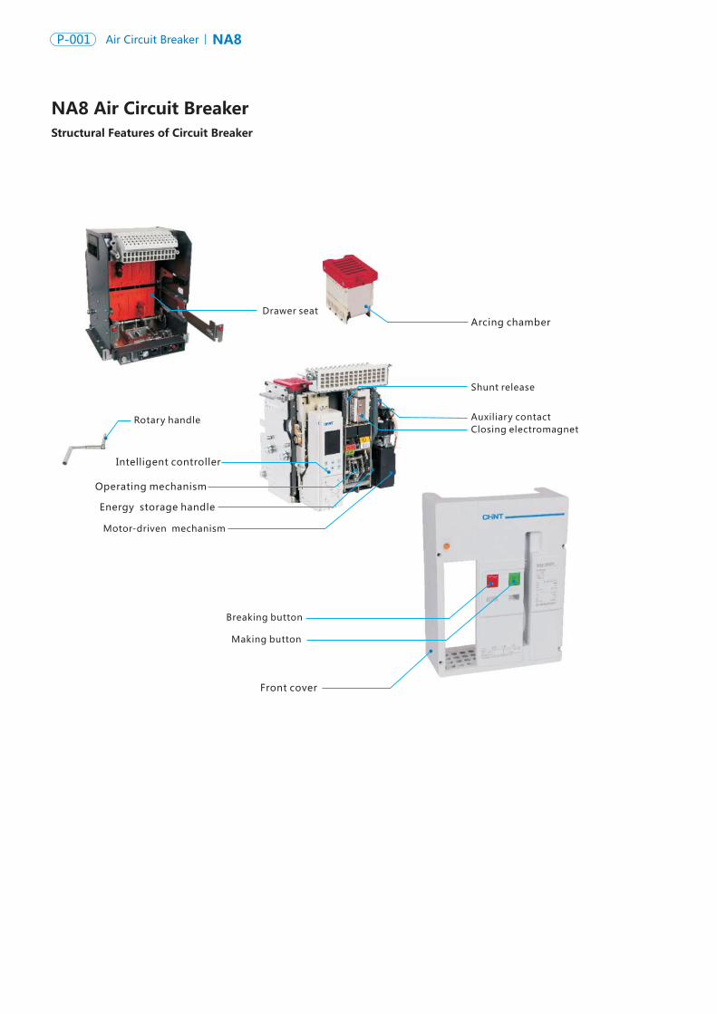
Identification of Circuit Breaker Panel
Trademark
Secondary wiring terminal
Breaking button
Energy- storage handle
Making button
Name plate
Energy-storage/release indicator
Breaking/Making indicator
Draw-out plate 1
2
3
4
5
6
9
Racking- handle entry
Position indicator
Rotary handle storage hole
Intelligent controller
Fault-breaking indicator reset button
15
16
Drawer padlock11
12
13
14
7
8
10
Three-position locking device10
“Connected” position, main circuit and secondary circuit are both connected
“Test”position, main circuit disconnected and isolated with safety barrier, only secondary circuit is connected
“Disconnected” position, main circuit and secondary circuit are both disconnected
Button does not pop up, and handle is free to rotate; Button pops up, and handle can not be rotated until button is reset manually.
: : : :
:
NA8 Air Circuit Breaker P-002P-001 NA8Air Circuit Breaker
Arcing chamber
Rotary handle
Intelligent controller
Operating mechanism
Energy storage handle
Drawer seat
Motor-driven mechanism
Shunt release
Closing electromagnetAuxiliary contact
Breaking button
Making button
Front cover
Structural Features of Circuit Breaker
NA8 Air Circuit Breaker
3
4
5
6
9
8
7
11
12
16
1
15
14
13
2
Identification of Circuit Breaker Panel
Trademark
Secondary wiring terminal
Breaking button
Energy- storage handle
Making button
Name plate
Energy-storage/release indicator
Breaking/Making indicator
Draw-out plate 1
2
3
4
5
6
9
Racking- handle entry
Position indicator
Rotary handle storage hole
Intelligent controller
Fault-breaking indicator reset button
15
16
Drawer padlock11
12
13
14
7
8
10
Three-position locking device10
“Connected” position, main circuit and secondary circuit are both connected
“Test”position, main circuit disconnected and isolated with safety barrier, only secondary circuit is connected
“Disconnected” position, main circuit and secondary circuit are both disconnected
Button does not pop up, and handle is free to rotate; Button pops up, and handle can not be rotated until button is reset manually.
: : : :
:
NA8 Air Circuit Breaker P-004P-003 NA8Air Circuit Breaker
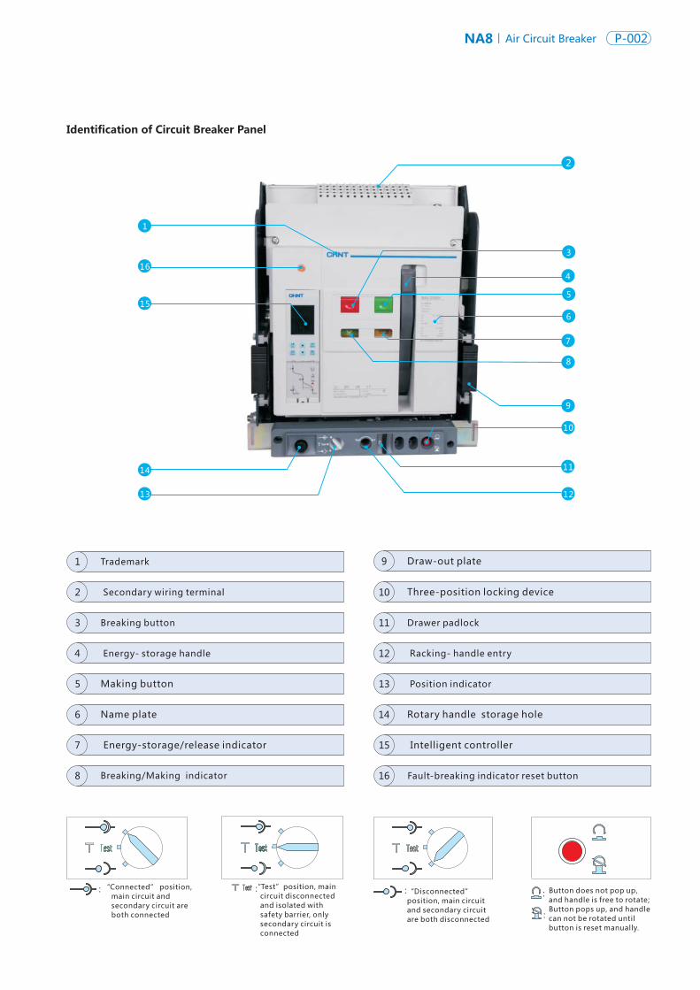
Circuit Breaker
Operating Conditions and Environmental
Suitability
● Frame size (A): 1600 , 2500, 4000, 7500
● Two kinds of breaking capacity: N, H (for 7500)
● Rated voltage Ue (VAC): 380/400/415, 690,
● Number of poles: 3 or 4 poles
● Mounting mode: draw-out type or fixed type
● Mode of connection: horizontal connection, vertical
connection, mixed connection
(In preparation...)
● NA8 products can operate normally at the following temperature.
Electric and mechanical characteristic applicable for ambient
temperature -5℃~+40℃ (certified), and also peripheral
ambient temperature -45℃~+70℃ (M type ), -20℃~+70℃
(H type ).
● For specific derating factor, see P23.
Storage conditions: Applicable for -45℃~+70℃.
● NA8 may resist against the following electromagnetic interference:
EMI-generated overvoltage;
Overvoltage caused by environmental disturbance or distribution system;
Radio wave (radio, interphone, radar, etc.)
Static discharge of terminal users
● NA8 circuit breakers have successfully accredited through the EMC test specified in the following standards:
IEC/ EN 60947-2
The above tests may ensure:
no false tripping fault, tripping time not interrupted.
● Protection grade
Front IP20 , other sides IP00
Intelligent Controller
Connection
Lock
Indication Contacts
● Rear connection
Horizontal connection, vertical connection, mixed connection are optional, and horizontal connection is of standard configuration
● Optional accessories
Interphase insulating barrier, NA8-1600 expansion busbar
● Key lock
● Drawer position padlock (to lock the circuit breaker at the
disconnected position)
● Drawer shutters padlock
● Breaking/Making button padlock
● Door interlock
● Standard contacts
Breaking/Making indication contact
Fault tripping indication contact
Spring energy storage indication contact
● Options
Drawer seat position indication contact
The ready to close contact may be added
(There is no such function for 1600A frame).
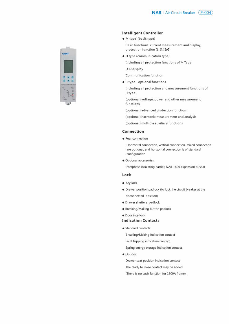
● M type (basic type)
Basic functions: current measurement and display, protection function (L, S, I&G)
● H type (communication type)
Including all protection functions of Type
LCD display
Communication function
● H type +optional functions
Including all protection and measurement functions of H type
(optional) voltage, power and other measurement functions
(optional) advanced protection function
(optional) harmonic measurement and analysis
(optional) multiple auxiliary functions
M
NA8 Air Circuit Breaker P-004P-003 NA8Air Circuit Breaker
Circuit Breaker
Operating Conditions and Environmental
Suitability
● Frame size (A): 1600 , 2500, 4000, 7500
● Two kinds of breaking capacity: N, H (for 7500)
● Rated voltage Ue (VAC): 380/400/415, 690,
● Number of poles: 3 or 4 poles
● Mounting mode: draw-out type or fixed type
● Mode of connection: horizontal connection, vertical
connection, mixed connection
(In preparation...)
● NA8 products can operate normally at the following temperature.
Electric and mechanical characteristic applicable for ambient
temperature -5℃~+40℃ (certified), and also peripheral
ambient temperature -45℃~+70℃ (M type ), -20℃~+70℃
(H type ).
● For specific derating factor, see P23.
Storage conditions: Applicable for -45℃~+70℃.
● NA8 may resist against the following electromagnetic interference:
EMI-generated overvoltage;
Overvoltage caused by environmental disturbance or distribution system;
Radio wave (radio, interphone, radar, etc.)
Static discharge of terminal users
● NA8 circuit breakers have successfully accredited through the EMC test specified in the following standards:
IEC/ EN 60947-2
The above tests may ensure:
no false tripping fault, tripping time not interrupted.
● Protection grade
Front IP20 , other sides IP00
Intelligent Controller
Connection
Lock
Indication Contacts
● Rear connection
Horizontal connection, vertical connection, mixed connection are optional, and horizontal connection is of standard configuration
● Optional accessories
Interphase insulating barrier, NA8-1600 expansion busbar
● Key lock
● Drawer position padlock (to lock the circuit breaker at the
disconnected position)
● Drawer shutters padlock
● Breaking/Making button padlock
● Door interlock
● Standard contacts
Breaking/Making indication contact
Fault tripping indication contact
Spring energy storage indication contact
● Options
Drawer seat position indication contact
The ready to close contact may be added
(There is no such function for 1600A frame).
● M type (basic type)
Basic functions: current measurement and display, protection function (L, S, I&G)
● H type (communication type)
Including all protection functions of Type
LCD display
Communication function
● H type +optional functions
Including all protection and measurement functions of H type
(optional) voltage, power and other measurement functions
(optional) advanced protection function
(optional) harmonic measurement and analysis
(optional) multiple auxiliary functions
M
NA8 Air Circuit Breaker P-006P-005 NA8Air Circuit Breaker
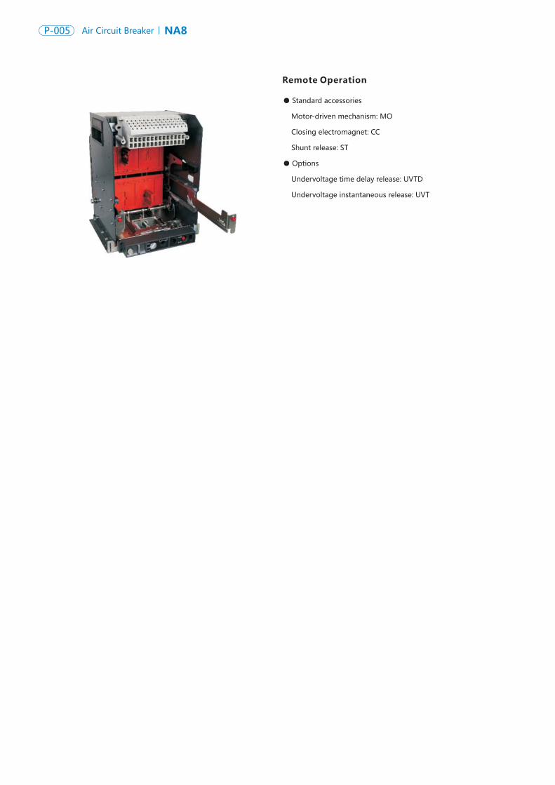
Remote Operation
● Standard accessories
Motor-driven mechanism: MO
Closing electromagnet: CC
Shunt release: ST
● Options
Undervoltage time delay release: UVTD
Undervoltage instantaneous release: UVT
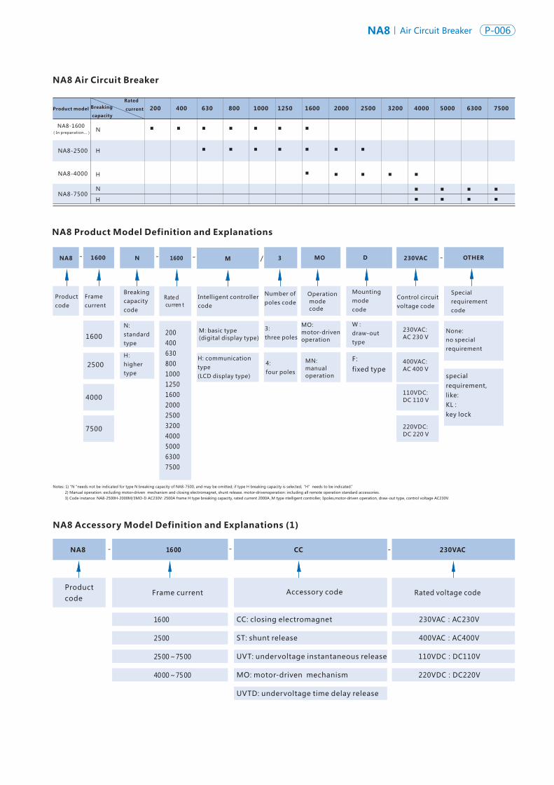
NA8 1600 N 31600 / D 230VAC OTHER
Product model Breaking
capacity
Rated
current
NA8-2500
NA8-4000
N
H
H
▪▪
▪
400 200
▪
630
▪▪
▪
800
▪
▪
1000
▪
▪
1250
▪
2000
▪
2500
▪
▪
3200
▪
▪
4000
▪
▪
1600 5000 6300 7500
▪ ▪NA8-7500
M
NA8 Air Circuit Breaker
NA8 Accessory Model Definition and Explanations (1)
MO
NA8 1600 CC 230VAC
Productcode
Frame current
Breaking capacitycode
Mounting modecode
Intelligent controllercode
Control circuitvoltage code
W :draw-out type
3:three poles
4:four poles
F:fixed type
Number ofpoles code
Special requirementcode
M: basic type(digital display type)1600
2500
4000
N:standard type
H:highertype
230VAC:AC 230 V
400VAC:AC 400 V
110VDC:DC 110 V
Operation mode code
MO:motor-driven operation
MN:manual operation
None:no specialrequirement
special requirement, like:KL : key lock
Productcode
Accessory code
1600
2500
2500~7500
4000~7500
CC: closing electromagnet
ST: shunt release
UVT: undervoltage instantaneous release
MO: motor-driven mechanism
UVTD: undervoltage time delay release
Rated voltage code
230VAC:AC230V
400VAC A 400V: C
110VDC D 110V: C
220VDC D 220V: C
H: communication type(LCD display type)
7500
2004006308001000125016002000250032004000500063007500
NA8 Product Model Definition and Explanations
Rate d curren t
220VDC:DC 220 V
Notes: 1) "N "needs not be indicated for type N breaking capacity of NA8-7500, and may be omitted; if type H breaking capacity is selected,“H”needs to be indicated.” 2) Manual operation: excluding motor-driven mechanism and closing electromagnet, shunt release. motor-drivenoperation: including all remote operation standard accessories. 3) Code instance: NA8-2500H-2000M/3MO-D AC230V: 2500A frame H type breaking capacity, rated current 2000A ,M type ntelligent controller, 3poles,motor-driven operation, draw-out type, control voltage AC230V.
▪
NA8-1600(In preparation...)
Frame current
N
H ▪▪ ▪ ▪
▪
NA8 Air Circuit Breaker P-006P-005 NA8Air Circuit Breaker
Remote Operation
● Standard accessories
Motor-driven mechanism: MO
Closing electromagnet: CC
Shunt release: ST
● Options
Undervoltage time delay release: UVTD
Undervoltage instantaneous release: UVT
NA8 1600 N 31600 / D 230VAC OTHER
Product model Breaking
capacity
Rated
current
NA8-2500
NA8-4000
N
H
H
▪▪
▪
400 200
▪
630
▪▪
▪
800
▪
▪
1000
▪
▪
1250
▪
2000
▪
2500
▪
▪
3200
▪
▪
4000
▪
▪
1600 5000 6300 7500
▪ ▪NA8-7500
M
NA8 Air Circuit Breaker
NA8 Accessory Model Definition and Explanations (1)
MO
NA8 1600 CC 230VAC
Productcode
Frame current
Breaking capacitycode
Mounting modecode
Intelligent controllercode
Control circuitvoltage code
W :draw-out type
3:three poles
4:four poles
F:fixed type
Number ofpoles code
Special requirementcode
M: basic type(digital display type)1600
2500
4000
N:standard type
H:highertype
230VAC:AC 230 V
400VAC:AC 400 V
110VDC:DC 110 V
Operation mode code
MO:motor-driven operation
MN:manual operation
None:no specialrequirement
special requirement, like:KL : key lock
Productcode
Accessory code
1600
2500
2500~7500
4000~7500
CC: closing electromagnet
ST: shunt release
UVT: undervoltage instantaneous release
MO: motor-driven mechanism
UVTD: undervoltage time delay release
Rated voltage code
230VAC:AC230V
400VAC A 400V: C
110VDC D 110V: C
220VDC D 220V: C
H: communication type(LCD display type)
7500
2004006308001000125016002000250032004000500063007500
NA8 Product Model Definition and Explanations
Rate d curren t
220VDC:DC 220 V
Notes: 1) "N "needs not be indicated for type N breaking capacity of NA8-7500, and may be omitted; if type H breaking capacity is selected,“H”needs to be indicated.” 2) Manual operation: excluding motor-driven mechanism and closing electromagnet, shunt release. motor-drivenoperation: including all remote operation standard accessories. 3) Code instance: NA8-2500H-2000M/3MO-D AC230V: 2500A frame H type breaking capacity, rated current 2000A ,M type ntelligent controller, 3poles,motor-driven operation, draw-out type, control voltage AC230V.
▪
NA8-1600(In preparation...)
Frame current
N
H ▪▪ ▪ ▪
▪
NA8 Air Circuit Breaker P-008P-007 NA8Air Circuit Breaker
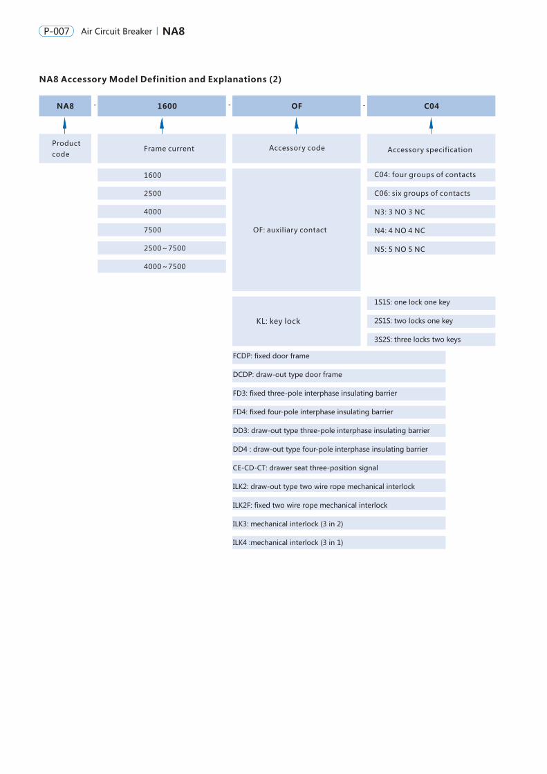
NA8 Accessory Model Definition and Explanations (2)
- - -NA8 1600 C04OF
Productcode
Frame current
1600
2500
4000
7500
2500~7500
Accessory specificationAccessory code
OF: auxiliary contact
KL: key lock
FCDP: fixed door frame
DCDP: draw-out type door frame
FD3: fixed three-pole interphase insulating barrier
FD4: fixed four-pole interphase insulating barrier
DD3: draw-out type three-pole interphase insulating barrier
DD4 : draw-out type four-pole interphase insulating barrier
CE-CD-CT: drawer seat three-position signal
ILK2: draw-out type two wire rope mechanical interlock
ILK2F: fixed two wire rope mechanical interlock
ILK3: mechanical interlock (3 in 2)
ILK4 :mechanical interlock (3 in 1)
Note
C04: four groups of contacts
C06: six groups of contacts
N3: 3 NO 3 NC
N4: 4 NO 4 NC
N5: 5 NO 5 NC
1S1S: one lock one key
2S1S: two locks one key
3S2S: three locks two keys
4000~7500

NA8 Air Circuit Breaker P-008P-007 NA8Air Circuit Breaker
NA8 Accessory Model Definition and Explanations (2)
- - -NA8 1600 C04OF
Productcode
Frame current
1600
2500
4000
7500
2500~7500
Accessory specificationAccessory code
OF: auxiliary contact
KL: key lock
FCDP: fixed door frame
DCDP: draw-out type door frame
FD3: fixed three-pole interphase insulating barrier
FD4: fixed four-pole interphase insulating barrier
DD3: draw-out type three-pole interphase insulating barrier
DD4 : draw-out type four-pole interphase insulating barrier
CE-CD-CT: drawer seat three-position signal
ILK2: draw-out type two wire rope mechanical interlock
ILK2F: fixed two wire rope mechanical interlock
ILK3: mechanical interlock (3 in 2)
ILK4 :mechanical interlock (3 in 1)
Note
C04: four groups of contacts
C06: six groups of contacts
N3: 3 NO 3 NC
N4: 4 NO 4 NC
N5: 5 NO 5 NC
1S1S: one lock one key
2S1S: two locks one key
3S2S: three locks two keys
4000~7500
135
3/4
380/400/415、690
12
50/60
Characteristics
IEC/EN 60947-2
IEC 60664-1
Frame size
Type of the circuit breaker
No maintenance
3P
4P
3P
4P
380/400/415V、690V
380/400/415V、690V
380/400/415V、690V
380/400/415V、690V
Icu
Ics
Icw 1s
Icw 3s
Icm
NA8-1600 (In preparation...)
630 800 1000 1250 1600 2000 2500
630 800 1000 1250 1600 2000 2500
20000 20000
8000 3000 8000 4000
▪ ▪
NA8-2500
H(415V) H(690V)
20~30
30~40
320×254×250
320×324×250
351×282×350
351×352×350
367×370×357
367×461×357
431×375×478
431×470×478
16
85
85
85
176
65
65
65
121
N:3
Applicable
0
55
42
42
121
B
10
30
25
25
63
N(400V) N(690V)
380/400/415V、690V
200 400 630 800 1000 1250 1600
200 400 630 800 1000 1250 1600
10000
6000 3000 500
▪ ▪
NA8-4000
1600 4000
1600
2000
2000
2500
2500
3200
3200
4000
4000 4000
5000
5000
6300
6300
7500
3750
50
100
100
B
100
20~30
30~40
402×422×341
402× ×341537
431.5×435×456
431.5×550×456
H(415V) H(690V)
50
75 75
26
85
85
85
220 187
NA8-7500
N(440V) N(690V) H(440V) H(690V)
135 100 150 100
100 135 100
B
135
26
20~30
30~45
1000
1500(440v) 1000(690v)
472×786×464
472×1016×464
20~30
30~40
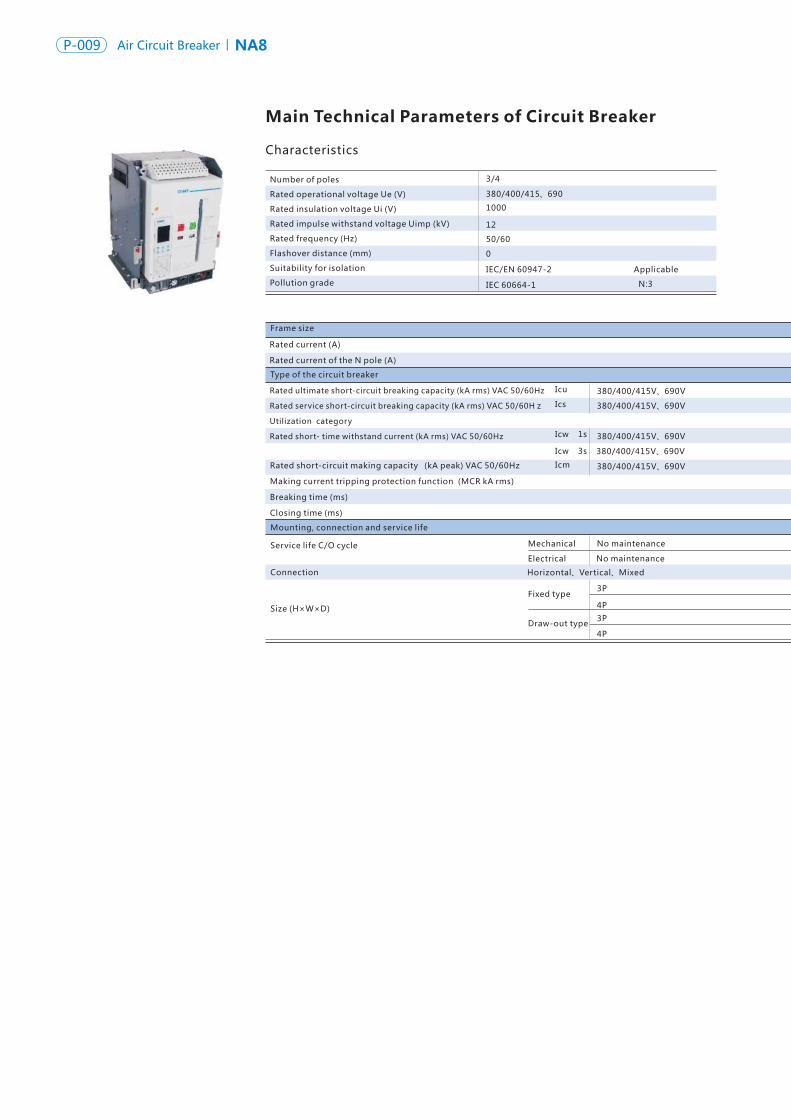
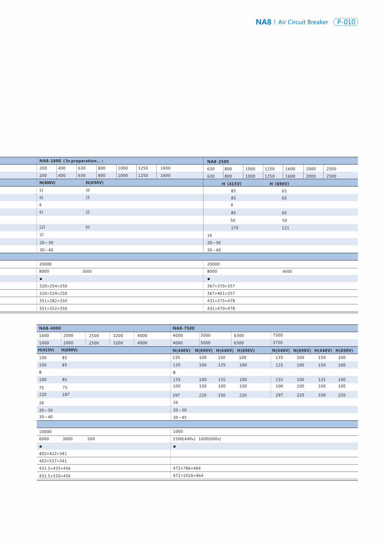
Main Technical Parameters of Circuit Breaker
Number of poles
Rated operational voltage Ue (V)
Rated insulation voltage Ui (V)
Rated impulse withstand voltage Uimp (kV)
Rated frequency (Hz)
Flashover distance (mm)
Suitability for isolation
Pollution grade
Rated current (A)
Rated current of the N pole (A)
Rated ultimate short-circuit breaking capacity (kA rms) VAC 50/60Hz
Rated service short-circuit breaking capacity (kA rms) VAC 50/60H z
Utilization category
Rated short- time withstand current (kA rms) VAC 50/60Hz
Rated short-circuit making capacity (kA peak) VAC 50/60Hz
Making current tripping protection function (MCR kA rms)
Breaking time (ms)
Closing time (ms)
Mounting, connection and service life
Service life C/O cycle
Connection
Size (H×W×D)
No maintenance
NA8 Air Circuit Breaker P-010P-009 NA8Air Circuit Breaker
N(440V) N(690V) H(440V) H(690V)
135 100 150 100
100
100 135 100
100 100 100
297 220 330 220
135 100 150 100
135 100 135 100
100 100 100 100
297 220 330 220
1000
Mechanical
Electrical
Fixed type
Draw-out type
Horizontal、Vertical、Mixed
B
135
3/4
380/400/415、690
12
50/60
Characteristics
IEC/EN 60947-2
IEC 60664-1
Frame size
Type of the circuit breaker
No maintenance
3P
4P
3P
4P
380/400/415V、690V
380/400/415V、690V
380/400/415V、690V
380/400/415V、690V
Icu
Ics
Icw 1s
Icw 3s
Icm
NA8-1600 (In preparation...)
630 800 1000 1250 1600 2000 2500
630 800 1000 1250 1600 2000 2500
20000 20000
8000 3000 8000 4000
▪ ▪
NA8-2500
H(415V) H(690V)
20~30
30~40
320×254×250
320×324×250
351×282×350
351×352×350
367×370×357
367×461×357
431×375×478
431×470×478
16
85
85
85
176
65
65
65
121
N:3
Applicable
0
55
42
42
121
B
10
30
25
25
63
N(400V) N(690V)
380/400/415V、690V
200 400 630 800 1000 1250 1600
200 400 630 800 1000 1250 1600
10000
6000 3000 500
▪ ▪
NA8-4000
1600 4000
1600
2000
2000
2500
2500
3200
3200
4000
4000 4000
5000
5000
6300
6300
7500
3750
50
100
100
B
100
20~30
30~40
402×422×341
402× ×341537
431.5×435×456
431.5×550×456
H(415V) H(690V)
50
75 75
26
85
85
85
220 187
NA8-7500
N(440V) N(690V) H(440V) H(690V)
135 100 150 100
100 135 100
B
135
26
20~30
30~45
1000
1500(440v) 1000(690v)
472×786×464
472×1016×464
20~30
30~40
Main Technical Parameters of Circuit Breaker
Number of poles
Rated operational voltage Ue (V)
Rated insulation voltage Ui (V)
Rated impulse withstand voltage Uimp (kV)
Rated frequency (Hz)
Flashover distance (mm)
Suitability for isolation
Pollution grade
Rated current (A)
Rated current of the N pole (A)
Rated ultimate short-circuit breaking capacity (kA rms) VAC 50/60Hz
Rated service short-circuit breaking capacity (kA rms) VAC 50/60H z
Utilization category
Rated short- time withstand current (kA rms) VAC 50/60Hz
Rated short-circuit making capacity (kA peak) VAC 50/60Hz
Making current tripping protection function (MCR kA rms)
Breaking time (ms)
Closing time (ms)
Mounting, connection and service life
Service life C/O cycle
Connection
Size (H×W×D)
No maintenance
NA8 Air Circuit Breaker P-010P-009 NA8Air Circuit Breaker
N(440V) N(690V) H(440V) H(690V)
135 100 150 100
100
100 135 100
100 100 100
297 220 330 220
135 100 150 100
135 100 135 100
100 100 100 100
297 220 330 220
1000
Mechanical
Electrical
Fixed type
Draw-out type
Horizontal、Vertical、Mixed
B
NA8 Air Circuit Breaker P-012P-011 NA8Air Circuit Breaker
1
2
3
4
5
6
7
8
9
10
11
12
13
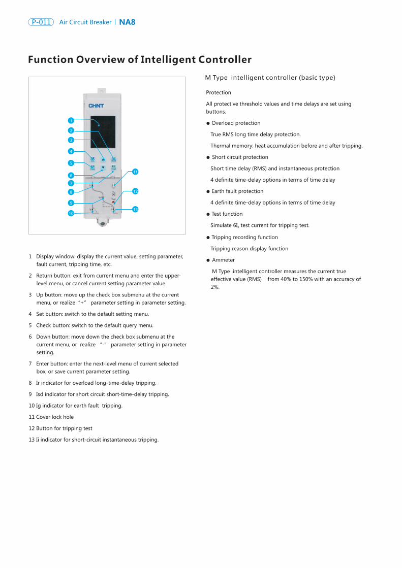
M Type intelligent controller (basic type)
1
2
3
4
5
6
7
8
9
10
11
12
13
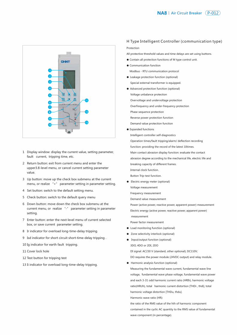
Function Overview of Intelligent ControllerH Type Intelligent Controller (communication type)
1 Display window: display the current value, setting parameter, fault current, tripping time, etc.
2 Return button: exit from current menu and enter the upper- level menu, or cancel current setting parameter value.
3 Up button: move up the check box submenu at the current menu, or realize“+” parameter setting in parameter setting.
4 Set button: switch to the default setting menu.
5 Check button: switch to the default query menu.
6 Down button: move down the check box submenu at the current menu, or realize “-” parameter setting in parameter setting.
7 Enter button: enter the next-level menu of current selected box, or save current parameter setting.
8 Ir indicator for overload long-time-delay tripping.
9 Isd indicator for short circuit short-time-delay tripping.
10 Ig indicator for earth fault tripping.
11 Cover lock hole
12 Button for tripping test
13 Ii indicator for short-circuit instantaneous tripping.
Protection
All protective threshold values and time delays are set using buttons.
● Overload protection
True RMS long time delay protection.
Thermal memory: heat accumulation before and after tripping.
● Short circuit protection
Short time delay (RMS) and instantaneous protection
4 definite time-delay options in terms of time delay
● Earth fault protection
4 definite time-delay options in terms of time delay
● Test function
Simulate 6I test current for tripping test.R
● Tripping recording function
Tripping reason display function
● Ammeter
M Type intelligent controller measures the current true effective value (RMS) from 40% to 150% with an accuracy of 2%.
1 Display window: display the current value, setting parameter, fault current, tripping time, etc.
2 Return button: exit from current menu and enter the upper3.8-level menu, or cancel current setting parameter value.
3 Up button: move up the check box submenu at the current menu, or realize “+” parameter setting in parameter setting.
4 Set button: switch to the default setting menu.
5 Check button: switch to the default query menu
6 Down button: move down the check box submenu at the current menu, or realize “-” parameter setting in parameter setting.
7 Enter button: enter the next-level menu of current selected box, or save current parameter setting.
8 Ir indicator for overload long-time-delay tripping.
9 Isd indicator for short circuit short-time-delay tripping .
10 Ig indicator for earth fault tripping.
11 Cover lock hole
12 Test button for tripping test
13 Ii indicator for overload long-time-delay tripping.
Protection
All protective threshold values and time delays are set using buttons.
● Contain all protection functions of M type control unit.
● Communication function
Modbus - RTU communication protocol
● Leakage protection function (optional)
Special external transformer is equipped.
● Advanced protection function (optional)
Voltage unbalance protection
Overvoltage and undervoltage protection
Overfrequency and under-frequency protection
Phase sequence protection
Reverse power protection function
Demand value protection function
● Expanded functions
Intelligent controller self-diagnostics
Operation times/fault tripping/alarm/ deflection recording
function: providing the record of the latest 10times.
Main contact abrasion display function: evaluate the contact
abrasion degree according to the mechanical life, electric life and
breaking capacity of different frames.
Internal clock function.
Button Trip-test function.
● Electric energy meter (optional)
Voltage measurement
Frequency measurement
Demand value measurement
Power (active power, reactive power, apparent power) measurement
Electric energy (active power, reactive power, apparent power)
measurement
Power factor measurement
● Load monitoring function (optional)
● Zone selectivity interlock (optional)
● Input/output function (optional)
3DO, 4DO or 2DI, 2DO
DI signal: AC230 V (standard, other optional); DC110V;
DO requires the power module (24VDC output) and relay module.
● Harmonic analysis function (optional)
Measuring the fundamental wave current, fundamental wave line
voltage, fundamental wave phase voltage, fundamental wave power
and each 3-31 odd harmonic current ratio (HRIh), harmonic voltage
ratio(HRUh), total harmonic current distortion [THDi , thdi], total
harmonic voltage distortion [THDu, thdu].
Harmonic wave ratio (HR):
the ratio of the RMS value of the hth of harmonic component
contained in the cyclic AC quantity to the RMS value of fundamental
wave component (in percentage).
NA8 Air Circuit Breaker P-012P-011 NA8Air Circuit Breaker
1
2
3
4
5
6
7
8
9
10
11
12
13
M Type intelligent controller (basic type)
1
2
3
4
5
6
7
8
9
10
11
12
13
Function Overview of Intelligent ControllerH Type Intelligent Controller (communication type)
1 Display window: display the current value, setting parameter, fault current, tripping time, etc.
2 Return button: exit from current menu and enter the upper- level menu, or cancel current setting parameter value.
3 Up button: move up the check box submenu at the current menu, or realize“+” parameter setting in parameter setting.
4 Set button: switch to the default setting menu.
5 Check button: switch to the default query menu.
6 Down button: move down the check box submenu at the current menu, or realize “-” parameter setting in parameter setting.
7 Enter button: enter the next-level menu of current selected box, or save current parameter setting.
8 Ir indicator for overload long-time-delay tripping.
9 Isd indicator for short circuit short-time-delay tripping.
10 Ig indicator for earth fault tripping.
11 Cover lock hole
12 Button for tripping test
13 Ii indicator for short-circuit instantaneous tripping.
Protection
All protective threshold values and time delays are set using buttons.
● Overload protection
True RMS long time delay protection.
Thermal memory: heat accumulation before and after tripping.
● Short circuit protection
Short time delay (RMS) and instantaneous protection
4 definite time-delay options in terms of time delay
● Earth fault protection
4 definite time-delay options in terms of time delay
● Test function
Simulate 6I test current for tripping test.R
● Tripping recording function
Tripping reason display function
● Ammeter
M Type intelligent controller measures the current true effective value (RMS) from 40% to 150% with an accuracy of 2%.
1 Display window: display the current value, setting parameter, fault current, tripping time, etc.
2 Return button: exit from current menu and enter the upper3.8-level menu, or cancel current setting parameter value.
3 Up button: move up the check box submenu at the current menu, or realize “+” parameter setting in parameter setting.
4 Set button: switch to the default setting menu.
5 Check button: switch to the default query menu
6 Down button: move down the check box submenu at the current menu, or realize “-” parameter setting in parameter setting.
7 Enter button: enter the next-level menu of current selected box, or save current parameter setting.
8 Ir indicator for overload long-time-delay tripping.
9 Isd indicator for short circuit short-time-delay tripping .
10 Ig indicator for earth fault tripping.
11 Cover lock hole
12 Test button for tripping test
13 Ii indicator for overload long-time-delay tripping.
Protection
All protective threshold values and time delays are set using buttons.
● Contain all protection functions of M type control unit.
● Communication function
Modbus - RTU communication protocol
● Leakage protection function (optional)
Special external transformer is equipped.
● Advanced protection function (optional)
Voltage unbalance protection
Overvoltage and undervoltage protection
Overfrequency and under-frequency protection
Phase sequence protection
Reverse power protection function
Demand value protection function
● Expanded functions
Intelligent controller self-diagnostics
Operation times/fault tripping/alarm/ deflection recording
function: providing the record of the latest 10times.
Main contact abrasion display function: evaluate the contact
abrasion degree according to the mechanical life, electric life and
breaking capacity of different frames.
Internal clock function.
Button Trip-test function.
● Electric energy meter (optional)
Voltage measurement
Frequency measurement
Demand value measurement
Power (active power, reactive power, apparent power) measurement
Electric energy (active power, reactive power, apparent power)
measurement
Power factor measurement
● Load monitoring function (optional)
● Zone selectivity interlock (optional)
● Input/output function (optional)
3DO, 4DO or 2DI, 2DO
DI signal: AC230 V (standard, other optional); DC110V;
DO requires the power module (24VDC output) and relay module.
● Harmonic analysis function (optional)
Measuring the fundamental wave current, fundamental wave line
voltage, fundamental wave phase voltage, fundamental wave power
and each 3-31 odd harmonic current ratio (HRIh), harmonic voltage
ratio(HRUh), total harmonic current distortion [THDi , thdi], total
harmonic voltage distortion [THDu, thdu].
Harmonic wave ratio (HR):
the ratio of the RMS value of the hth of harmonic component
contained in the cyclic AC quantity to the RMS value of fundamental
wave component (in percentage).
NA8 Air Circuit Breaker P-014P-013 NA8Air Circuit Breaker
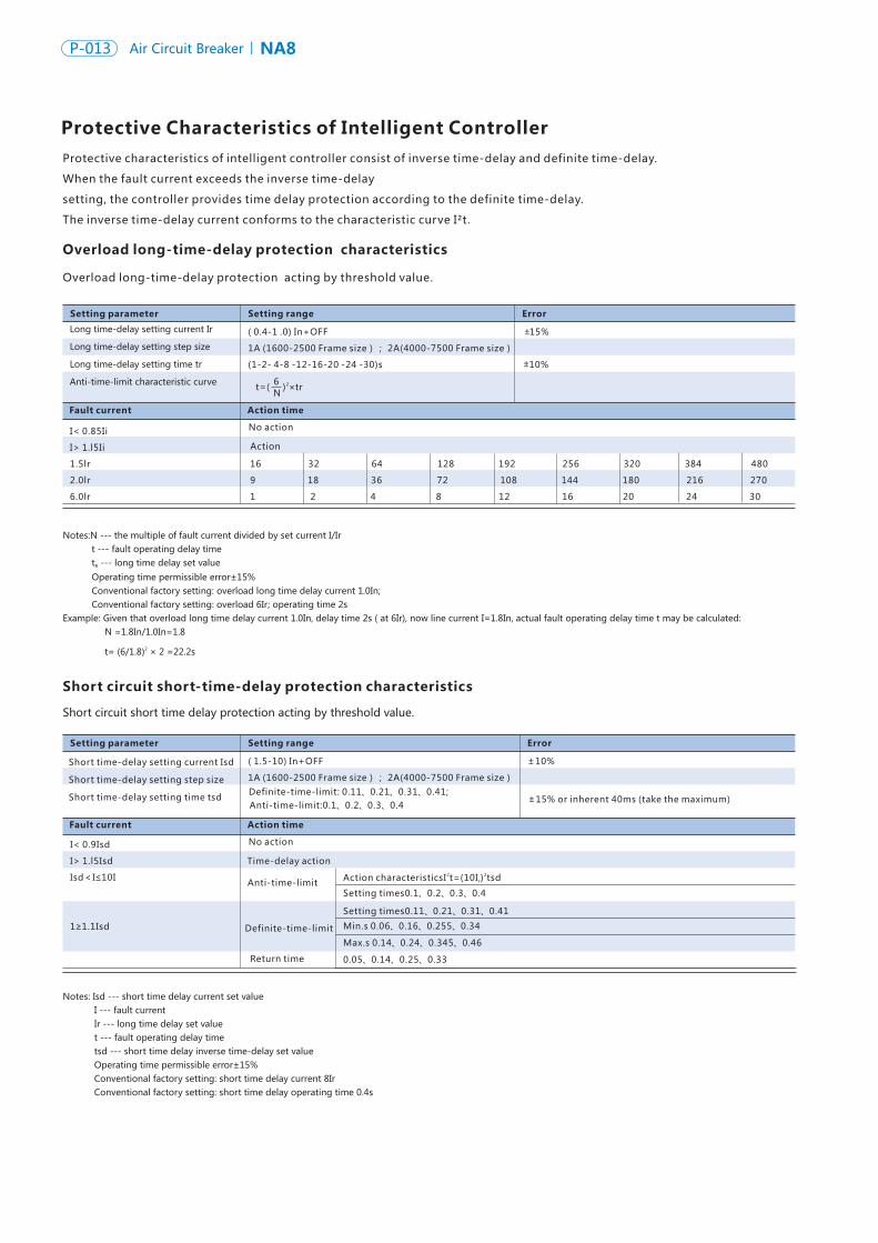
Protective Characteristics of Intelligent ControllerProtective characteristics of intelligent controller consist of inverse time-delay and definite time-delay.
When the fault current exceeds the inverse time-delay
setting, the controller provides time delay protection according to the definite time-delay.
The inverse time-delay current conforms to the characteristic curve I²t.
Overload long-time-delay protection characteristics
Short circuit short-time-delay protection characteristics
Notes:N --- the multiple of fault current divided by set current I/Ir t --- fault operating delay time t --- long time delay set valueR
Operating time permissible error±15% Conventional factory setting: overload long time delay current 1.0In; Conventional factory setting: overload 6Ir; operating time 2sExample: Given that overload long time delay current 1.0In, delay time 2s ( at 6Ir), now line current I=1.8In, actual fault operating delay time t may be calculated: N =1.8In/1.0In=1.8
2 t= (6/1.8) × 2 =22.2s
Short circuit short time delay protection acting by threshold value.
Notes: Isd --- short time delay current set value I --- fault current Ir --- long time delay set value t --- fault operating delay time tsd --- short time delay inverse time-delay set value Operating time permissible error±15% Conventional factory setting: short time delay current 8Ir Conventional factory setting: short time delay operating time 0.4s
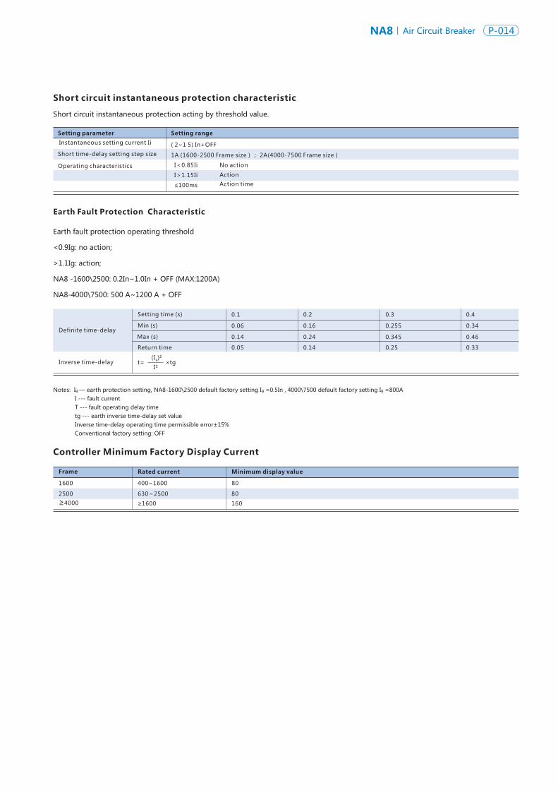
Earth Fault Protection Characteristic
Controller Minimum Factory Display Current
Frame
1600
2500
≥4000
Definite time-delay
Setting time (s)
Min (s)
Max (s)
0.1 0.2 0.3 0.4
Minimum display value
80
80
160
0.06 0.16 0.255 0.34
0.14 0.24 0.345 0.46
Return time 0.05 0.14 0.25 0.33
Rated current
400~1600
630~2500
≥1600
t=I²
(I )²g×tgInverse time-delay
Short circuit instantaneous protection characteristic
Short circuit instantaneous protection acting by threshold value.
Earth fault protection operating threshold
<0.9Ig: no action;
>1.1Ig: action;
NA8 -1600\2500: 0.2In~1.0In + OFF (MAX:1200A)
NA8-4000\7500: 500 A~1200 A + OFF
Notes: Ig — earth protection setting, NA8-1600\2500 default factory setting Ig =0.5In , 4000\7500 default factory setting Ig =800A I --- fault current T --- fault operating delay time tg --- earth inverse time-delay set value Inverse time-delay operating time permissible error±15% Conventional factory setting: OFF
Overload long-time-delay protection acting by threshold value.
Setting parameter Setting range Error
Long time-delay setting current Ir
Long time-delay setting step size
Long time-delay setting time tr
Anti-time-limit characteristic curve
Fault current Action time
I< 0.85Ii
I> 1.l5Ii
1.5lr 16 32 64 128 192 256 320 384 480
2.0lr 9 18 36 72 108 144 180 216 270
6.0lr 1 2 4 8 12 16 20 24 30
No action
Action
( 0.4-1 .0) In+OFF 15%
1A (1600-2500 Frame size); 2A(4000-7500 Frame size)
(1-2- 4-8 -12-16-20 -24 -30)s 10%
N6t=( 2) ×tr
Setting parameter Setting range Error
Fault current Action time
I< 0.9Isd
I> 1.l5Isd
Isd<I≤10I
1≥1.1Isd
No action
( 1.5-10) In+OFF 10%
1A (1600-2500 Frame size); 2A(4000-7500 Frame size)
Short time-delay setting current Isd
Short time-delay setting step size
Short time-delay setting time tsd Definite-time-limit: 0.11、0.21、0.31、0.41;Anti-time-limit:0.1、0.2、0.3、0.4
15% or inherent 40ms (take the maximum)
±
±
±
±
Time-delay action
Anti-time-limit
Definite-time-limit
Return time
Setting times0.1、0.2、0.3、0.4
Setting times0.11、0.21、0.31、0.41
Min.s 0.06、0.16、0.255、0.34
Max.s 0.14、0.24、0.345、0.46
0.05、0.14、0.25、0.33
2 2Action characteristicsI t=(10I ) tsdr
Setting parameter Setting range
( 2~1 5) In+OFF
1A (1600-2500 Frame size); 2A(4000-7500 Frame size)
Instantaneous setting current Ii
Short time-delay setting step size
Operating characteristics I<0.85Ii
I>1.15Ii Action
Action time≤100ms
No action
NA8 Air Circuit Breaker P-014P-013 NA8Air Circuit Breaker
Protective Characteristics of Intelligent ControllerProtective characteristics of intelligent controller consist of inverse time-delay and definite time-delay.
When the fault current exceeds the inverse time-delay
setting, the controller provides time delay protection according to the definite time-delay.
The inverse time-delay current conforms to the characteristic curve I²t.
Overload long-time-delay protection characteristics
Short circuit short-time-delay protection characteristics
Notes:N --- the multiple of fault current divided by set current I/Ir t --- fault operating delay time t --- long time delay set valueR
Operating time permissible error±15% Conventional factory setting: overload long time delay current 1.0In; Conventional factory setting: overload 6Ir; operating time 2sExample: Given that overload long time delay current 1.0In, delay time 2s ( at 6Ir), now line current I=1.8In, actual fault operating delay time t may be calculated: N =1.8In/1.0In=1.8
2 t= (6/1.8) × 2 =22.2s
Short circuit short time delay protection acting by threshold value.
Notes: Isd --- short time delay current set value I --- fault current Ir --- long time delay set value t --- fault operating delay time tsd --- short time delay inverse time-delay set value Operating time permissible error±15% Conventional factory setting: short time delay current 8Ir Conventional factory setting: short time delay operating time 0.4s
Earth Fault Protection Characteristic
Controller Minimum Factory Display Current
Frame
1600
2500
≥4000
Definite time-delay
Setting time (s)
Min (s)
Max (s)
0.1 0.2 0.3 0.4
Minimum display value
80
80
160
0.06 0.16 0.255 0.34
0.14 0.24 0.345 0.46
Return time 0.05 0.14 0.25 0.33
Rated current
400~1600
630~2500
≥1600
t=I²
(I )²g×tgInverse time-delay
Short circuit instantaneous protection characteristic
Short circuit instantaneous protection acting by threshold value.
Earth fault protection operating threshold
<0.9Ig: no action;
>1.1Ig: action;
NA8 -1600\2500: 0.2In~1.0In + OFF (MAX:1200A)
NA8-4000\7500: 500 A~1200 A + OFF
Notes: Ig — earth protection setting, NA8-1600\2500 default factory setting Ig =0.5In , 4000\7500 default factory setting Ig =800A I --- fault current T --- fault operating delay time tg --- earth inverse time-delay set value Inverse time-delay operating time permissible error±15% Conventional factory setting: OFF
Overload long-time-delay protection acting by threshold value.
Setting parameter Setting range Error
Long time-delay setting current Ir
Long time-delay setting step size
Long time-delay setting time tr
Anti-time-limit characteristic curve
Fault current Action time
I< 0.85Ii
I> 1.l5Ii
1.5lr 16 32 64 128 192 256 320 384 480
2.0lr 9 18 36 72 108 144 180 216 270
6.0lr 1 2 4 8 12 16 20 24 30
No action
Action
( 0.4-1 .0) In+OFF 15%
1A (1600-2500 Frame size); 2A(4000-7500 Frame size)
(1-2- 4-8 -12-16-20 -24 -30)s 10%
N6t=( 2) ×tr
Setting parameter Setting range Error
Fault current Action time
I< 0.9Isd
I> 1.l5Isd
Isd<I≤10I
1≥1.1Isd
No action
( 1.5-10) In+OFF 10%
1A (1600-2500 Frame size); 2A(4000-7500 Frame size)
Short time-delay setting current Isd
Short time-delay setting step size
Short time-delay setting time tsd Definite-time-limit: 0.11、0.21、0.31、0.41;Anti-time-limit:0.1、0.2、0.3、0.4
15% or inherent 40ms (take the maximum)
±
±
±
±
Time-delay action
Anti-time-limit
Definite-time-limit
Return time
Setting times0.1、0.2、0.3、0.4
Setting times0.11、0.21、0.31、0.41
Min.s 0.06、0.16、0.255、0.34
Max.s 0.14、0.24、0.345、0.46
0.05、0.14、0.25、0.33
2 2Action characteristicsI t=(10I ) tsdr
Setting parameter Setting range
( 2~1 5) In+OFF
1A (1600-2500 Frame size); 2A(4000-7500 Frame size)
Instantaneous setting current Ii
Short time-delay setting step size
Operating characteristics I<0.85Ii
I>1.15Ii Action
Action time≤100ms
No action
NA8 Air Circuit Breaker P-016P-015 NA8Air Circuit Breaker
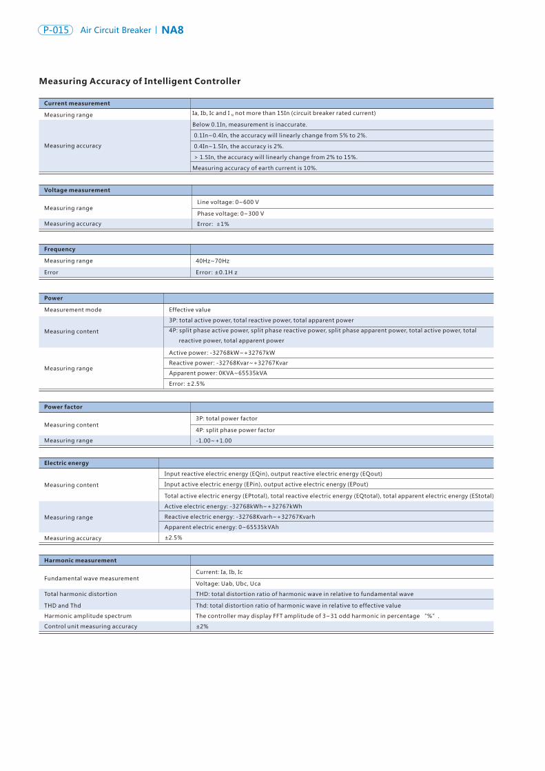
Current measurement
Measuring range
Measuring accuracy
Voltage measurement
Measuring range
Measuring accuracy
Frequency
Measuring range
Error
Power
Measurement mode
Measuring content
Measuring range
Power factor
Measuring content
Measuring range
Electric energy
Measuring content
Measuring range
Measuring accuracy
Harmonic measurement
Fundamental wave measurement
Total harmonic distortion
THD and Thd
Harmonic amplitude spectrum
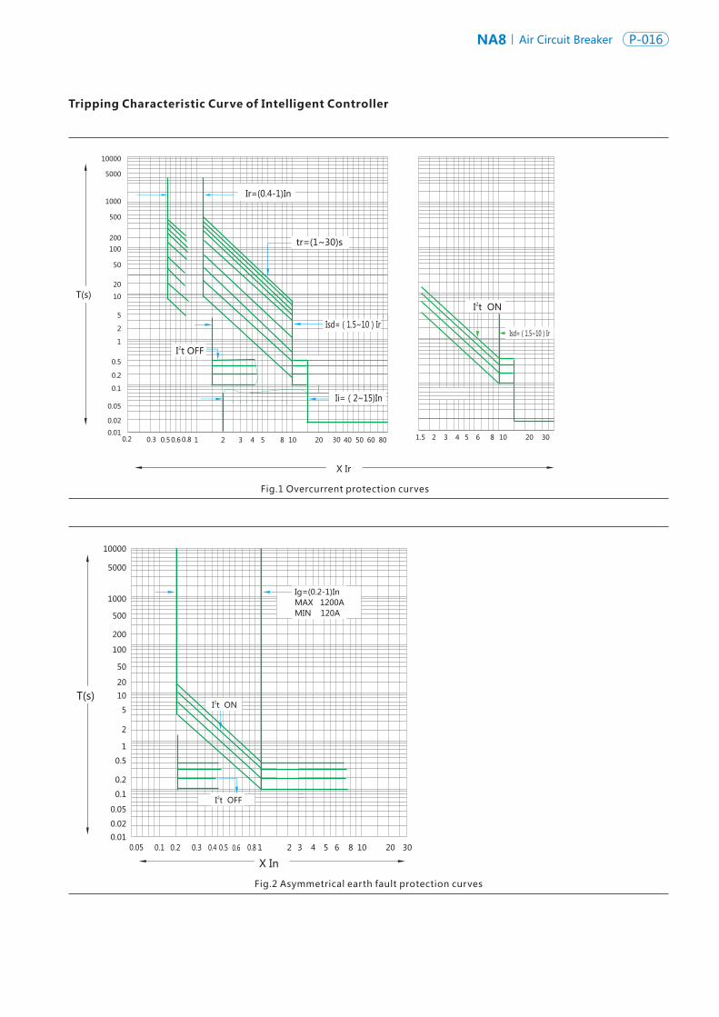
Measuring Accuracy of Intelligent Controller Tripping Characteristic Curve of Intelligent Controller
Line voltage: 0~600 V
Phase voltage: 0~300 V
Error: ±1%
40Hz~70Hz
Error: ±0.1H z
Effective value
3P: total active power, total reactive power, total apparent power
4P: split phase active power, split phase reactive power, split phase apparent power, total active power, total
reactive power, total apparent power
Active power: -32768kW~+32767kW
Reactive power: -32768Kvar~+32767Kvar
Apparent power: 0KVA~65535kVA
Error: ±2.5%
3P: total power factor
4P: split phase power factor
-1.00~+1.00
Input active electric energy (EPin), output active electric energy (EPout)
Input reactive electric energy (EQin), output reactive electric energy (EQout)
Total active electric energy (EPtotal), total reactive electric energy (EQtotal), total apparent electric energy (EStotal)
Active electric energy: -32768kWh~+32767kWh
Reactive electric energy: -32768Kvarh~+32767Kvarh
Apparent electric energy: 0~65535kVAh
±2.5%
Current: Ia, Ib, Ic
Voltage: Uab, Ubc, Uca
THD: total distortion ratio of harmonic wave in relative to fundamental wave
Thd: total distortion ratio of harmonic wave in relative to effective value
The controller may display FFT amplitude of 3~31 odd harmonic in percentage “%”.
Control unit measuring accuracy ±2%
T(s)
X Ir
0.2 0.3 0.6 1 2 3 4 5 8 10 20 30 50 800.5 0.8 40 60
10000
5000
1000
500
200
100
50
20
10
5
2
1
0.5
0.2
0.1
0.05
0.02
0.018 10 20 3021.5 43 5 6
Isd=(1.5~10)Ir
Ir=(0.4-1)In
Ii=(2~15)In
2I t OFF
tr=(1~30)s
2I t ON
Isd=(1.5~10)Ir
T(s)
X In0.1 0.2 0.3 0.4 0.6 1 2 3 4 5 6 8 10 20 300.05 0.8
10000
5000
1000
500
200
100
50
20
10
5
2
1
0.5
0.2
0.1
0.05
0.02
0.010.5
Ig=(0.2-1)InMAX 1200AMIN 120A
2 I t ON
2 I t OFF
Ia, Ib, Ic and I not more than 15In (circuit breaker rated current)N
Below 0.1In, measurement is inaccurate.
0.1In~0.4In, the accuracy will linearly change from 5% to 2%.
0.4In~1.5In, the accuracy is 2%.
> 1.5In, the accuracy will linearly change from 2% to 15%.
Measuring accuracy of earth current is 10%.
Fig.1 Overcurrent protection curves
Fig.2 Asymmetrical earth fault protection curves
NA8 Air Circuit Breaker P-016P-015 NA8Air Circuit Breaker
Current measurement
Measuring range
Measuring accuracy
Voltage measurement
Measuring range
Measuring accuracy
Frequency
Measuring range
Error
Power
Measurement mode
Measuring content
Measuring range
Power factor
Measuring content
Measuring range
Electric energy
Measuring content
Measuring range
Measuring accuracy
Harmonic measurement
Fundamental wave measurement
Total harmonic distortion
THD and Thd
Harmonic amplitude spectrum
Measuring Accuracy of Intelligent Controller Tripping Characteristic Curve of Intelligent Controller
Line voltage: 0~600 V
Phase voltage: 0~300 V
Error: ±1%
40Hz~70Hz
Error: ±0.1H z
Effective value
3P: total active power, total reactive power, total apparent power
4P: split phase active power, split phase reactive power, split phase apparent power, total active power, total
reactive power, total apparent power
Active power: -32768kW~+32767kW
Reactive power: -32768Kvar~+32767Kvar
Apparent power: 0KVA~65535kVA
Error: ±2.5%
3P: total power factor
4P: split phase power factor
-1.00~+1.00
Input active electric energy (EPin), output active electric energy (EPout)
Input reactive electric energy (EQin), output reactive electric energy (EQout)
Total active electric energy (EPtotal), total reactive electric energy (EQtotal), total apparent electric energy (EStotal)
Active electric energy: -32768kWh~+32767kWh
Reactive electric energy: -32768Kvarh~+32767Kvarh
Apparent electric energy: 0~65535kVAh
±2.5%
Current: Ia, Ib, Ic
Voltage: Uab, Ubc, Uca
THD: total distortion ratio of harmonic wave in relative to fundamental wave
Thd: total distortion ratio of harmonic wave in relative to effective value
The controller may display FFT amplitude of 3~31 odd harmonic in percentage “%”.
Control unit measuring accuracy ±2%
T(s)
X Ir
0.2 0.3 0.6 1 2 3 4 5 8 10 20 30 50 800.5 0.8 40 60
10000
5000
1000
500
200
100
50
20
10
5
2
1
0.5
0.2
0.1
0.05
0.02
0.018 10 20 3021.5 43 5 6
Isd=(1.5~10)Ir
Ir=(0.4-1)In
Ii=(2~15)In
2I t OFF
tr=(1~30)s
2I t ON
Isd=(1.5~10)Ir
T(s)
X In0.1 0.2 0.3 0.4 0.6 1 2 3 4 5 6 8 10 20 300.05 0.8
10000
5000
1000
500
200
100
50
20
10
5
2
1
0.5
0.2
0.1
0.05
0.02
0.010.5
Ig=(0.2-1)InMAX 1200AMIN 120A
2 I t ON
2 I t OFF
Ia, Ib, Ic and I not more than 15In (circuit breaker rated current)N
Below 0.1In, measurement is inaccurate.
0.1In~0.4In, the accuracy will linearly change from 5% to 2%.
0.4In~1.5In, the accuracy is 2%.
> 1.5In, the accuracy will linearly change from 2% to 15%.
Measuring accuracy of earth current is 10%.
Fig.1 Overcurrent protection curves
Fig.2 Asymmetrical earth fault protection curves
NA8 Air Circuit Breaker P-018P-017 NA8Air Circuit Breaker
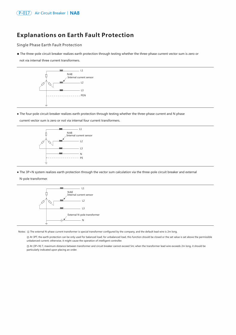
Single Phase Earth Fault Protection
Explanations on Earth Fault Protection
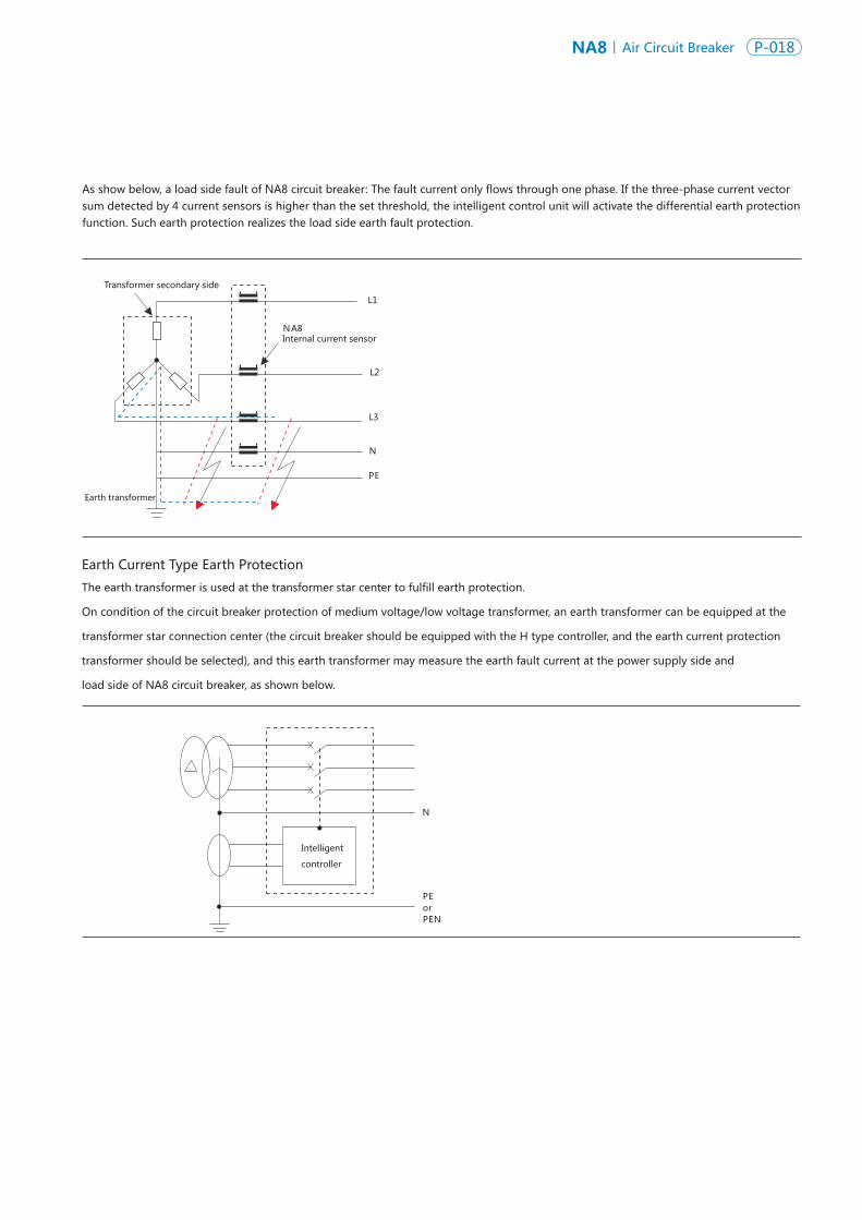
Earth Current Type Earth Protection
L1
L2
L3
PEN
NA8
NA8
NA8
Internal current sensor
Internal current sensor
Internal current sensor
External N-pole transformer
L1
L2
L3
PE
N
L2
L3
N
L1
Intelligent
controller
N
NA8Internal current sensor
L2
L3
N
L1
PE
Transformer secondary side
Earth transformer
Notes: ① The external N-phase current transformer is special transformer configured by the company, and the default lead wire is 2m long.
② At 3PT, the earth protection can be only used for balanced load; for unbalanced load, this function should be closed or the set value is set above the permissible unbalanced current; otherwise, it might cause the operation of intelligent controller.
③ At (3P+N) T, maximum distance between transformer and circuit breaker cannot exceed 5m; when the transformer lead wire exceeds 2m long, it should be particularly indicated upon placing an order.
● The three-pole circuit breaker realizes earth protection through testing whether the three-phase current vector sum is zero or
not via internal three current transformers.
● The four-pole circuit breaker realizes earth protection through testing whether the three-phase current and N phase
current vector sum is zero or not via internal four current transformers.
● The 3P+N system realizes earth protection through the vector sum calculation via the three-pole circuit breaker and external
N-pole transformer.
The earth transformer is used at the transformer star center to fulfill earth protection.
On condition of the circuit breaker protection of medium voltage/low voltage transformer, an earth transformer can be equipped at the
transformer star connection center (the circuit breaker should be equipped with the H type controller, and the earth current protection
transformer should be selected), and this earth transformer may measure the earth fault current at the power supply side and
load side of NA8 circuit breaker, as shown below.
PEorPEN
As show below, a load side fault of NA8 circuit breaker: The fault current only flows through one phase. If the three-phase current vector sum detected by 4 current sensors is higher than the set threshold, the intelligent control unit will activate the differential earth protection function. Such earth protection realizes the load side earth fault protection.
NA8 Air Circuit Breaker P-018P-017 NA8Air Circuit Breaker
Single Phase Earth Fault Protection
Explanations on Earth Fault Protection
Earth Current Type Earth Protection
L1
L2
L3
PEN
NA8
NA8
NA8
Internal current sensor
Internal current sensor
Internal current sensor
External N-pole transformer
L1
L2
L3
PE
N
L2
L3
N
L1
Intelligent
controller
N
NA8Internal current sensor
L2
L3
N
L1
PE
Transformer secondary side
Earth transformer
Notes: ① The external N-phase current transformer is special transformer configured by the company, and the default lead wire is 2m long.
② At 3PT, the earth protection can be only used for balanced load; for unbalanced load, this function should be closed or the set value is set above the permissible unbalanced current; otherwise, it might cause the operation of intelligent controller.
③ At (3P+N) T, maximum distance between transformer and circuit breaker cannot exceed 5m; when the transformer lead wire exceeds 2m long, it should be particularly indicated upon placing an order.
● The three-pole circuit breaker realizes earth protection through testing whether the three-phase current vector sum is zero or
not via internal three current transformers.
● The four-pole circuit breaker realizes earth protection through testing whether the three-phase current and N phase
current vector sum is zero or not via internal four current transformers.
● The 3P+N system realizes earth protection through the vector sum calculation via the three-pole circuit breaker and external
N-pole transformer.
The earth transformer is used at the transformer star center to fulfill earth protection.
On condition of the circuit breaker protection of medium voltage/low voltage transformer, an earth transformer can be equipped at the
transformer star connection center (the circuit breaker should be equipped with the H type controller, and the earth current protection
transformer should be selected), and this earth transformer may measure the earth fault current at the power supply side and
load side of NA8 circuit breaker, as shown below.
PEorPEN
As show below, a load side fault of NA8 circuit breaker: The fault current only flows through one phase. If the three-phase current vector sum detected by 4 current sensors is higher than the set threshold, the intelligent control unit will activate the differential earth protection function. Such earth protection realizes the load side earth fault protection.
NA8 Air Circuit Breaker P-020P-019 NA8Air Circuit Breaker
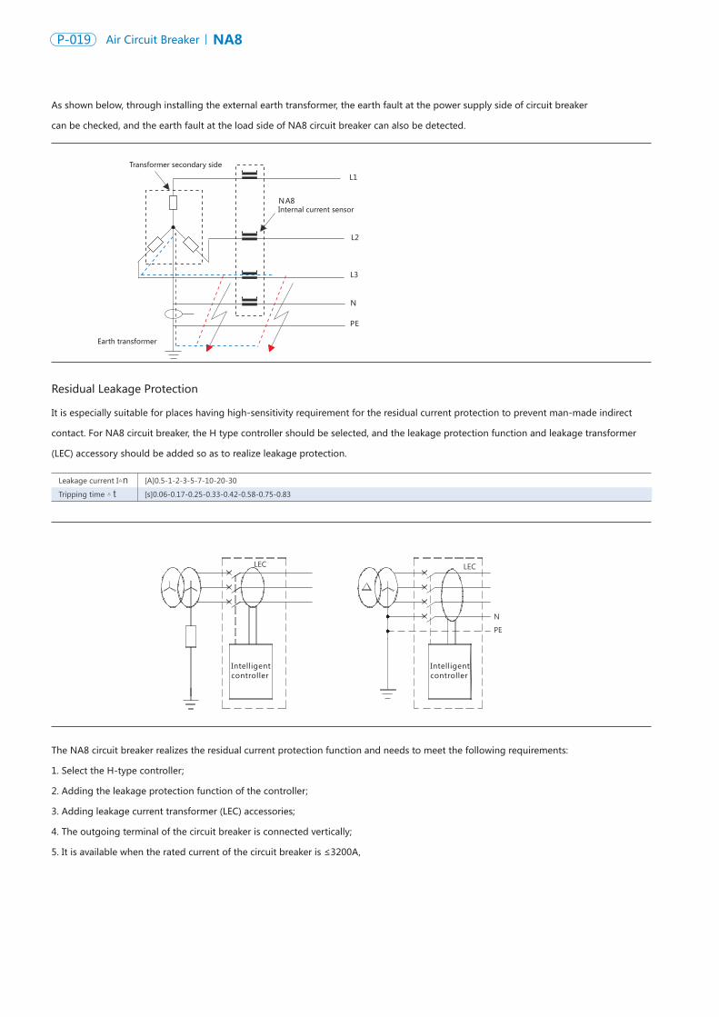
As shown below, through installing the external earth transformer, the earth fault at the power supply side of circuit breaker
can be checked, and the earth fault at the load side of NA8 circuit breaker can also be detected.
NA8Internal current sensor
L2
L3
N
L1
PE
Transformer secondary side
Earth transformer
Residual Leakage Protection
It is especially suitable for places having high-sensitivity requirement for the residual current protection to prevent man-made indirect
contact. For NA8 circuit breaker, the H type controller should be selected, and the leakage protection function and leakage transformer
(LEC) accessory should be added so as to realize leakage protection.
Leakage current I△n [A]0.5-1-2-3-5-7-10-20-30
Tripping time △ t [s]0.06-0.17-0.25-0.33-0.42-0.58-0.75-0.83
LEC LEC
N
PE
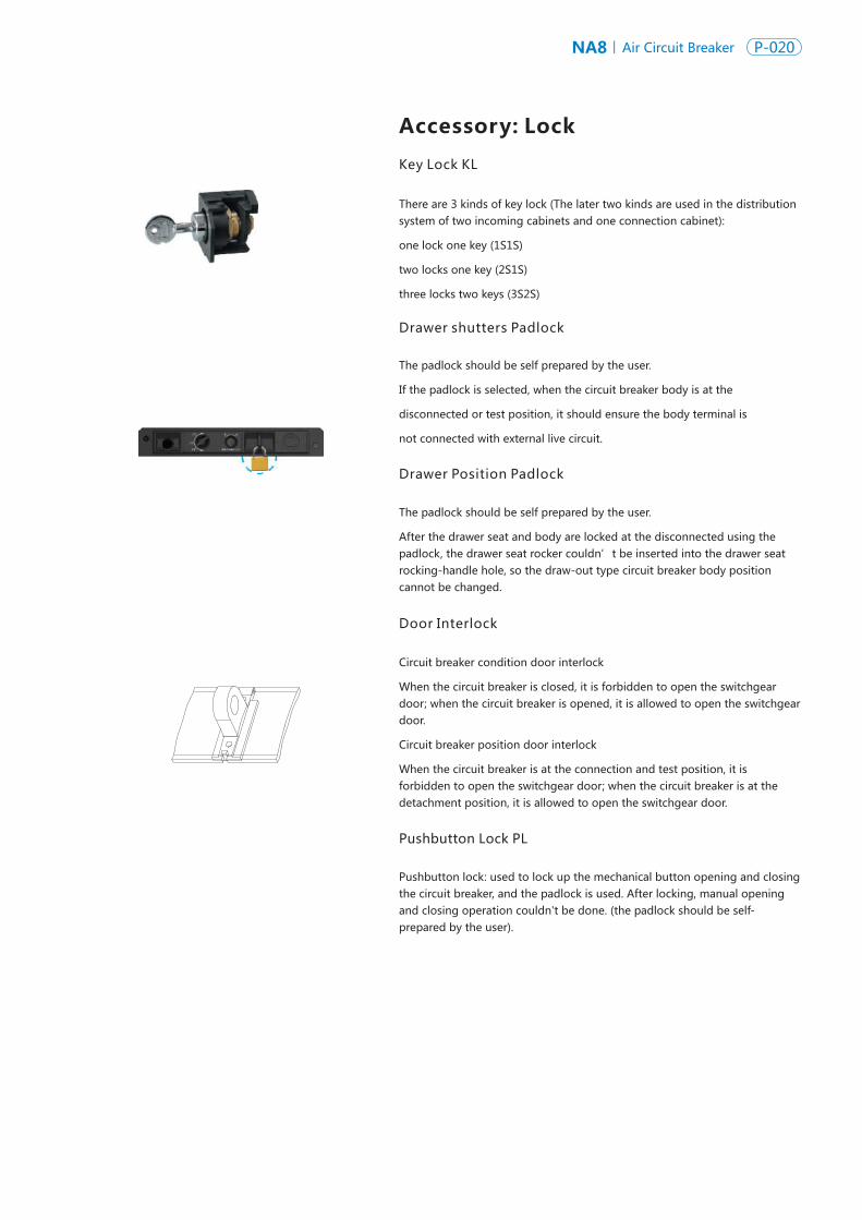
Drawer shutters Padlock
Drawer Position Padlock
Key Lock KL
Door Interlock
Accessory: Lock
Pushbutton Lock PL
There are 3 kinds of key lock (The later two kinds are used in the distribution system of two incoming cabinets and one connection cabinet):
one lock one key (1S1S)
two locks one key (2S1S)
three locks two keys (3S2S)
The padlock should be self prepared by the user.
After the drawer seat and body are locked at the disconnected using the padlock, the drawer seat rocker couldn’t be inserted into the drawer seat rocking-handle hole, so the draw-out type circuit breaker body position cannot be changed.
Circuit breaker condition door interlock
When the circuit breaker is closed, it is forbidden to open the switchgear door; when the circuit breaker is opened, it is allowed to open the switchgear door.
Circuit breaker position door interlock
When the circuit breaker is at the connection and test position, it is forbidden to open the switchgear door; when the circuit breaker is at the detachment position, it is allowed to open the switchgear door.
Pushbutton lock: used to lock up the mechanical button opening and closing the circuit breaker, and the padlock is used. After locking, manual opening and closing operation couldn't be done. (the padlock should be self-prepared by the user).
The padlock should be self prepared by the user.
If the padlock is selected, when the circuit breaker body is at the
disconnected or test position, it should ensure the body terminal is
not connected with external live circuit.
Intelligent controller
Intelligent controller
The NA8 circuit breaker realizes the residual current protection function and needs to meet the following requirements:
1. Select the H-type controller;
2. Adding the leakage protection function of the controller;
3. Adding leakage current transformer (LEC) accessories;
4. The outgoing terminal of the circuit breaker is connected vertically;
5. It is available when the rated current of the circuit breaker is ≤3200A,
NA8 Air Circuit Breaker P-020P-019 NA8Air Circuit Breaker
As shown below, through installing the external earth transformer, the earth fault at the power supply side of circuit breaker
can be checked, and the earth fault at the load side of NA8 circuit breaker can also be detected.
NA8Internal current sensor
L2
L3
N
L1
PE
Transformer secondary side
Earth transformer
Residual Leakage Protection
It is especially suitable for places having high-sensitivity requirement for the residual current protection to prevent man-made indirect
contact. For NA8 circuit breaker, the H type controller should be selected, and the leakage protection function and leakage transformer
(LEC) accessory should be added so as to realize leakage protection.
Leakage current I△n [A]0.5-1-2-3-5-7-10-20-30
Tripping time △ t [s]0.06-0.17-0.25-0.33-0.42-0.58-0.75-0.83
LEC LEC
N
PE
Drawer shutters Padlock
Drawer Position Padlock
Key Lock KL
Door Interlock
Accessory: Lock
Pushbutton Lock PL
There are 3 kinds of key lock (The later two kinds are used in the distribution system of two incoming cabinets and one connection cabinet):
one lock one key (1S1S)
two locks one key (2S1S)
three locks two keys (3S2S)
The padlock should be self prepared by the user.
After the drawer seat and body are locked at the disconnected using the padlock, the drawer seat rocker couldn’t be inserted into the drawer seat rocking-handle hole, so the draw-out type circuit breaker body position cannot be changed.
Circuit breaker condition door interlock
When the circuit breaker is closed, it is forbidden to open the switchgear door; when the circuit breaker is opened, it is allowed to open the switchgear door.
Circuit breaker position door interlock
When the circuit breaker is at the connection and test position, it is forbidden to open the switchgear door; when the circuit breaker is at the detachment position, it is allowed to open the switchgear door.
Pushbutton lock: used to lock up the mechanical button opening and closing the circuit breaker, and the padlock is used. After locking, manual opening and closing operation couldn't be done. (the padlock should be self-prepared by the user).
The padlock should be self prepared by the user.
If the padlock is selected, when the circuit breaker body is at the
disconnected or test position, it should ensure the body terminal is
not connected with external live circuit.
Intelligent controller
Intelligent controller
The NA8 circuit breaker realizes the residual current protection function and needs to meet the following requirements:
1. Select the H-type controller;
2. Adding the leakage protection function of the controller;
3. Adding leakage current transformer (LEC) accessories;
4. The outgoing terminal of the circuit breaker is connected vertically;
5. It is available when the rated current of the circuit breaker is ≤3200A,
NA8 Air Circuit Breaker P-022P-021 NA8Air Circuit Breaker
1QF 2QF
0
1
0
0
0
1
1QF 2QF
Circuit diagram Possible mode of operation
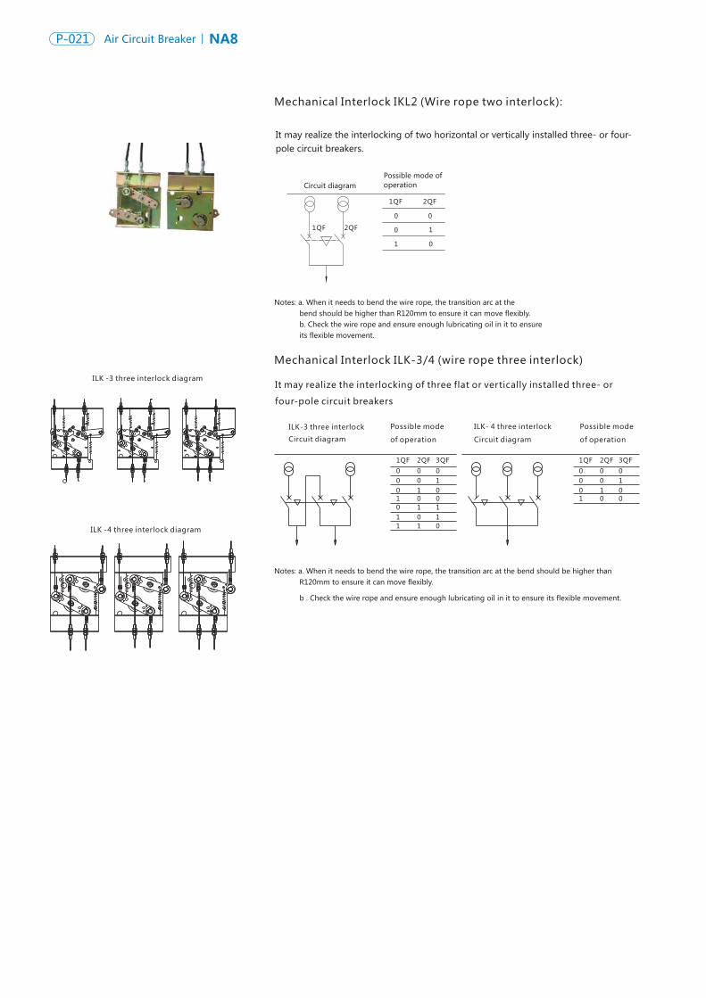
Mechanical Interlock IKL2 (Wire rope two interlock):
It may realize the interlocking of two horizontal or vertically installed three- or four-pole circuit breakers.
Notes: a. When it needs to bend the wire rope, the transition arc at the bend should be higher than R120mm to ensure it can move flexibly. b. Check the wire rope and ensure enough lubricating oil in it to ensure its flexible movement.
Standard configuration
Breaking capacity
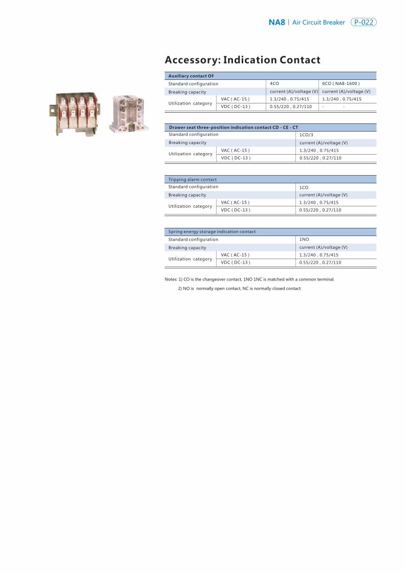
Tripping alarm contact
1CO
Spring energy storage indication contact
1NO
Drawer seat three-position indication contact CD - CE - CT
1CO/3
current (A)/voltage (V)
current (A)/voltage (V)
current (A)/voltage (V)
current (A)/voltage (V)
VAC(AC-15)
VAC(AC-15)
VAC(AC-15)
VAC(AC-15)
VDC(DC-13)
VDC(DC-13)
VDC(DC-13)
VDC(DC-13)
1.3/240,0.75/415
1.3/240,0.75/415
1.3/240,0.75/415
1.3/240,0.75/415
0.55/220,0.27/110
0.55/220,0.27/110
0.55/220,0.27/110
0.55/220,0.27/110
Utilization category
Auxiliary contact OF
Accessory: Indication Contact
4CO
1.3/240,0.75/415
6CO(NA8-1600)
- -
Mechanical Interlock ILK-3/4 (wire rope three interlock)
It may realize the interlocking of three flat or vertically installed three- or
four-pole circuit breakers
ILK -4 three interlock diagram
ILK -3 three interlock diagram
ILK-3 three interlock
Circuit diagram
Possible mode
of operation
1QF
0
2QF
0
3QF
00 0 10 1 01 0 00 1 11 0 11 1 0
ILK- 4 three interlock
Circuit diagram
1QF
0
2QF
0
3QF
00 0 10 1 01 0 0
Possible mode
of operation
Notes: a. When it needs to bend the wire rope, the transition arc at the bend should be higher than R120mm to ensure it can move flexibly.
b . Check the wire rope and ensure enough lubricating oil in it to ensure its flexible movement.
current (A)/voltage (V)
Standard configuration
Breaking capacity
Utilization category
Standard configuration
Breaking capacity
Utilization category
Standard configuration
Breaking capacity
Utilization category
Notes: 1) CO is the changeover contact, 1NO 1NC is matched with a common terminal.
2) NO is normally open contact, NC is normally closed contact.
NA8 Air Circuit Breaker P-022P-021 NA8Air Circuit Breaker
1QF 2QF
0
1
0
0
0
1
1QF 2QF
Circuit diagram Possible mode of operation
Mechanical Interlock IKL2 (Wire rope two interlock):
It may realize the interlocking of two horizontal or vertically installed three- or four-pole circuit breakers.
Notes: a. When it needs to bend the wire rope, the transition arc at the bend should be higher than R120mm to ensure it can move flexibly. b. Check the wire rope and ensure enough lubricating oil in it to ensure its flexible movement.
Standard configuration
Breaking capacity
Tripping alarm contact
1CO
Spring energy storage indication contact
1NO
Drawer seat three-position indication contact CD - CE - CT
1CO/3
current (A)/voltage (V)
current (A)/voltage (V)
current (A)/voltage (V)
current (A)/voltage (V)
VAC(AC-15)
VAC(AC-15)
VAC(AC-15)
VAC(AC-15)
VDC(DC-13)
VDC(DC-13)
VDC(DC-13)
VDC(DC-13)
1.3/240,0.75/415
1.3/240,0.75/415
1.3/240,0.75/415
1.3/240,0.75/415
0.55/220,0.27/110
0.55/220,0.27/110
0.55/220,0.27/110
0.55/220,0.27/110
Utilization category
Auxiliary contact OF
Accessory: Indication Contact
4CO
1.3/240,0.75/415
6CO(NA8-1600)
- -
Mechanical Interlock ILK-3/4 (wire rope three interlock)
It may realize the interlocking of three flat or vertically installed three- or
four-pole circuit breakers
ILK -4 three interlock diagram
ILK -3 three interlock diagram
ILK-3 three interlock
Circuit diagram
Possible mode
of operation
1QF
0
2QF
0
3QF
00 0 10 1 01 0 00 1 11 0 11 1 0
ILK- 4 three interlock
Circuit diagram
1QF
0
2QF
0
3QF
00 0 10 1 01 0 0
Possible mode
of operation
Notes: a. When it needs to bend the wire rope, the transition arc at the bend should be higher than R120mm to ensure it can move flexibly.
b . Check the wire rope and ensure enough lubricating oil in it to ensure its flexible movement.
current (A)/voltage (V)
Standard configuration
Breaking capacity
Utilization category
Standard configuration
Breaking capacity
Utilization category
Standard configuration
Breaking capacity
Utilization category
Notes: 1) CO is the changeover contact, 1NO 1NC is matched with a common terminal.
2) NO is normally open contact, NC is normally closed contact.
NA8 Air Circuit Breaker P-024P-023 NA8Air Circuit Breaker
Characteristic
Power supplyVAC 50/60Hz
VDC
Operating threshold
Frame: power consumption (VA or W)
Motor over-current time
Energy storage time
Operating frequency
Characteristic
Characteristic
Power supply
Operating voltage
Frame: power consumption (VA or W)AC
AC
DC
DC
Circuit breaker response time
VAC 50/60Hz
VAC 50/60Hz
VDC
VDC
CC
ST
220/230/240,380/400/415
110 220,
0.85-1.1Us
1600:75W;2500:85W;4000~7500:180W
≤1min
≤7s
≤2times/min
220/230/240
220/230/240
380/400/415
380/400/415
220,110
220,110
0.85-1.1Us
0.85-1.1Us
400VA
400VA
1600:380W 2500、4000~7500:130W;
1600:380W;2500、4000~7500:130W
30ms-45ms
25ms-35ms
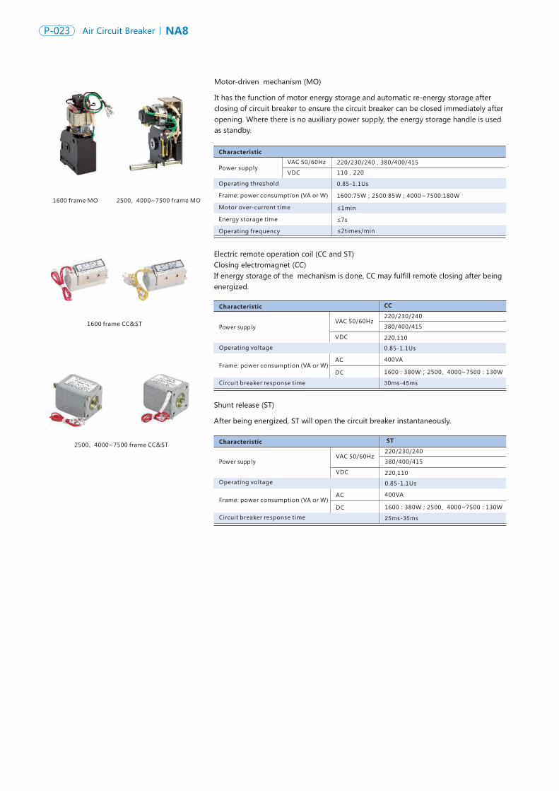
1600 frame MO 2500、4000~7500 frame MO
1600 frame CC&ST
2500、4000~7500 frame CC&ST
Characteristic
Power supply
Operating threshold
Frame: power consumption (W)
VAC 50/60Hz
VDC
Opening 0.35-0.7Ue
0.85Ue
220/230/240,380/400/415_
0.35-0.7Ue
0.85-1.1Ue
1600:220W/15W2500、4000~7500:220W/13W
;
Characteristic
Power supply
Operating threshold
Frame: power consumption (VA)
Adjustable time
VAC 50/60Hz
0.35-0.7Ue
0.85Ue
1600:20VA;25000、4000~7500:48VA
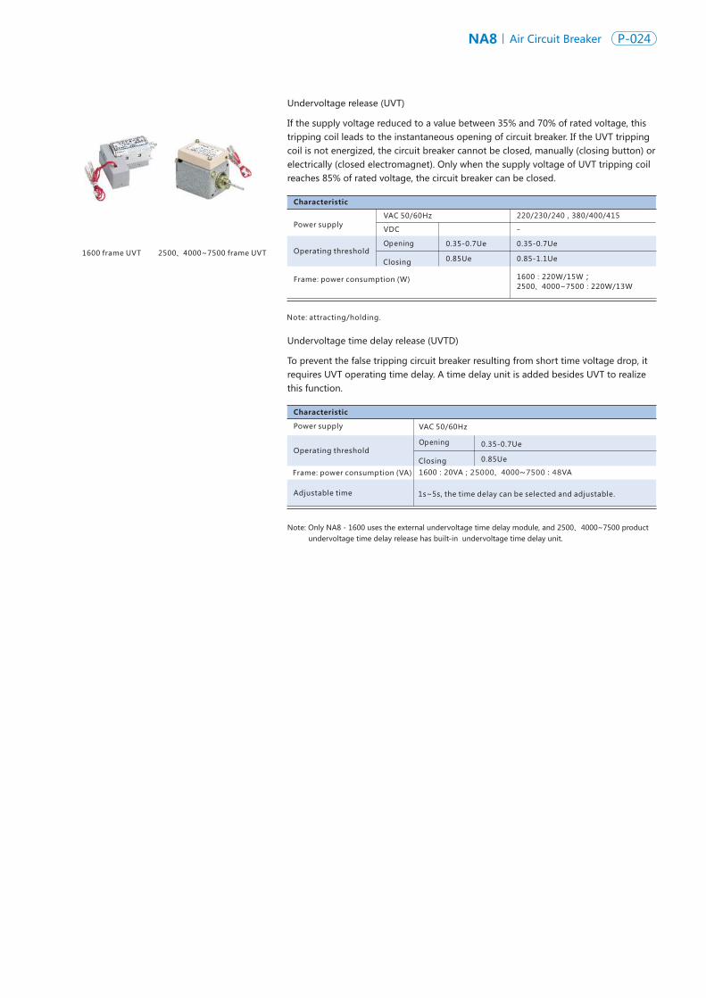
1600 frame UVT 2500、4000~7500 frame UVT
Motor-driven mechanism (MO)
It has the function of motor energy storage and automatic re-energy storage after closing of circuit breaker to ensure the circuit breaker can be closed immediately after opening. Where there is no auxiliary power supply, the energy storage handle is used as standby.
Electric remote operation coil (CC and ST) Closing electromagnet (CC)If energy storage of the mechanism is done, CC may fulfill remote closing after being energized.
Power supply
Operating voltage
Frame: power consumption (VA or W)
Circuit breaker response time
Shunt release (ST)
After being energized, ST will open the circuit breaker instantaneously.
Undervoltage release (UVT)
If the supply voltage reduced to a value between 35% and 70% of rated voltage, this tripping coil leads to the instantaneous opening of circuit breaker. If the UVT tripping coil is not energized, the circuit breaker cannot be closed, manually (closing button) or electrically (closed electromagnet). Only when the supply voltage of UVT tripping coil reaches 85% of rated voltage, the circuit breaker can be closed.
Closing
Opening
Closing
Note: attracting/holding.
Undervoltage time delay release (UVTD)
To prevent the false tripping circuit breaker resulting from short time voltage drop, it requires UVT operating time delay. A time delay unit is added besides UVT to realize this function.
Note: Only NA8 - 1600 uses the external undervoltage time delay module, and 2500、4000~7500 product undervoltage time delay release has built-in undervoltage time delay unit.
1s~5s, the time delay can be selected and adjustable.
NA8 Air Circuit Breaker P-024P-023 NA8Air Circuit Breaker
Characteristic
Power supplyVAC 50/60Hz
VDC
Operating threshold
Frame: power consumption (VA or W)
Motor over-current time
Energy storage time
Operating frequency
Characteristic
Characteristic
Power supply
Operating voltage
Frame: power consumption (VA or W)AC
AC
DC
DC
Circuit breaker response time
VAC 50/60Hz
VAC 50/60Hz
VDC
VDC
CC
ST
220/230/240,380/400/415
110 220,
0.85-1.1Us
1600:75W;2500:85W;4000~7500:180W
≤1min
≤7s
≤2times/min
220/230/240
220/230/240
380/400/415
380/400/415
220,110
220,110
0.85-1.1Us
0.85-1.1Us
400VA
400VA
1600:380W 2500、4000~7500:130W;
1600:380W;2500、4000~7500:130W
30ms-45ms
25ms-35ms
1600 frame MO 2500、4000~7500 frame MO
1600 frame CC&ST
2500、4000~7500 frame CC&ST
Characteristic
Power supply
Operating threshold
Frame: power consumption (W)
VAC 50/60Hz
VDC
Opening 0.35-0.7Ue
0.85Ue
220/230/240,380/400/415_
0.35-0.7Ue
0.85-1.1Ue
1600:220W/15W2500、4000~7500:220W/13W
;
Characteristic
Power supply
Operating threshold
Frame: power consumption (VA)
Adjustable time
VAC 50/60Hz
0.35-0.7Ue
0.85Ue
1600:20VA;25000、4000~7500:48VA
1600 frame UVT 2500、4000~7500 frame UVT
Motor-driven mechanism (MO)
It has the function of motor energy storage and automatic re-energy storage after closing of circuit breaker to ensure the circuit breaker can be closed immediately after opening. Where there is no auxiliary power supply, the energy storage handle is used as standby.
Electric remote operation coil (CC and ST) Closing electromagnet (CC)If energy storage of the mechanism is done, CC may fulfill remote closing after being energized.
Power supply
Operating voltage
Frame: power consumption (VA or W)
Circuit breaker response time
Shunt release (ST)
After being energized, ST will open the circuit breaker instantaneously.
Undervoltage release (UVT)
If the supply voltage reduced to a value between 35% and 70% of rated voltage, this tripping coil leads to the instantaneous opening of circuit breaker. If the UVT tripping coil is not energized, the circuit breaker cannot be closed, manually (closing button) or electrically (closed electromagnet). Only when the supply voltage of UVT tripping coil reaches 85% of rated voltage, the circuit breaker can be closed.
Closing
Opening
Closing
Note: attracting/holding.
Undervoltage time delay release (UVTD)
To prevent the false tripping circuit breaker resulting from short time voltage drop, it requires UVT operating time delay. A time delay unit is added besides UVT to realize this function.
Note: Only NA8 - 1600 uses the external undervoltage time delay module, and 2500、4000~7500 product undervoltage time delay release has built-in undervoltage time delay unit.
1s~5s, the time delay can be selected and adjustable.
NA8 Air Circuit Breaker P-026P-025 NA8Air Circuit Breaker
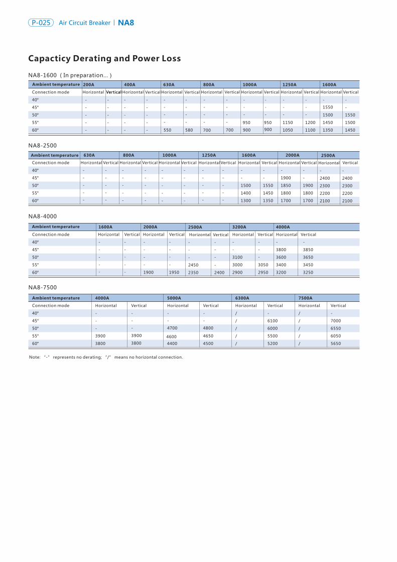
Capacticy Derating and Power Loss
NA8-1600 (In preparation...)
Connection mode
40°
45°
50°
55°
60°
400A 630A 800A 1000A 1250A 1600A
Horizontal Vertical Horizontal Vertical Horizontal Vertical Horizontal Vertical Horizontal Vertical Horizontal Vertical
NA8-2500
630A 800A 1000A 1250A 1600A 2000A
NA8-4000
NA8-7500
4000A 5000A 6300A
Connection mode
40°
45°
50°
55°
60°
Horizontal Horizontal Horizontal Vertical Horizontal Vertical Horizontal Vertical Horizontal Vertical
Ambient temperature
Connection mode
Connection mode
40°
40°
45°
45°
50°
50°
55°
55°
60°
60°
Horizontal Vertical Horizontal Vertical Horizontal Vertical
-
-
-
-
-
-
-
-
-
-
-
-
-
-
550
-
-
-
-
580
-
-
-
-
700
-
-
-
-
700
-
-
-
950
900
-
-
-
950
900
-
-
-
1150
1050
-
-
-
1200
1100
-
1550
1500
1450
1350
-
-
1550
1500
1450
-
-
-
-
-
-
-
-
-
-
-
-
-
-
-
-
-
-
-
-
-
-
-
-
-
-
-
-
-
-
-
-
-
-
-
-
-
-
-
-
-
-
1500
1400
1300
-
-
1550
1450
1350
-
1900
1850
1800
1700
-
-
1900
1800
1700
-
-
-
3900
3800
-
-
-
3900
3800
-
-
4700
4600
4400
-
-
4800
4650
4500
/
/
/
/
/
-
6100
6000
5500
5200
Note: “-” represents no derating; “/” means no horizontal connection.
200A
Horizontal Vertical
-
-
-
-
-
-
-
-
-
-
2500A
Horizontal Vertical
-
2400
2300
2200
2100
-
2400
2300
2200
2100
3200A 4000A
Horizontal Vertical Horizontal Vertical
-
-
3100
3000
2900
-
-
-
3050
2950
-
3800
3600
3400
3200
-
3850
3650
3450
3250
2500A
Horizontal Vertical
-
-
-
2450
2350
-
-
-
-
2400
2000A
Horizontal Vertical
-
-
-
-
1900
-
-
-
-
1950
7500A
Horizontal Vertical
/
/
/
/
/
-
7000
6550
6050
5650
Altitude Capacity Derating Factor
Power loss
Power loss is the power consumption per pole measured at In, 50/60 Hz.
Frame
1600A(In preparation...)
2500A
4000A
Rated current (A)
400
200
630
800
1000
1250
1600
630
800
1000
1250
1600
2000
2500
2000
4000
4000
3200
2500
5000
7500
6300
Power loss of draw-out type (W) Power loss of fixed type (W)
140
115
161
215
230
250
460
470
550
670
1047
58.6
73.7
172
268
440
530
600
7500A
550
590
950
1500
80
45
100
110
120
130
220
26.4
36.6
78
122
200
262
312
250
280
656
420
-
-
-
-
Altitude (m)
2000
2500
3000
3500
4000
4500
5000
2000
Rated operating current (Ie)
3000 4000 5000
Uimp
1.0Ie
Ui
0.93Ie
0.88Ie
0.83Ie
0.78Ie
0.73Ie
The factory must be contacted for confirmation
Ue
Voltage performance corrections under different altitudes
Current performance corrections under different altitudes
12
1000
2200
690
10
800
1955
580
8.5
700
1760
500
7.5
600
1600
400
Ambient temperature
Ambient temperature
Ambient temperature
Vertical
Vertical Vertical
Altitude (m)
Rated impusle withstand voltage (kV)
Average insulation grade (V)
Power frequency withstand voltage (V)
Maximum operational voltage (V )
Note: If the ambient temperature is lower than 40 ℃, Ie = In ; if the ambient temperature is higher than 40 ℃, derating use must be done in strict accordance with the requirement of operation manual; in such case, Ie ≠ In , Ie and In can be looked up according to the temperature derating table.1600A
Horizontal Vertical
-
-
-
-
-
-
-
-
- -
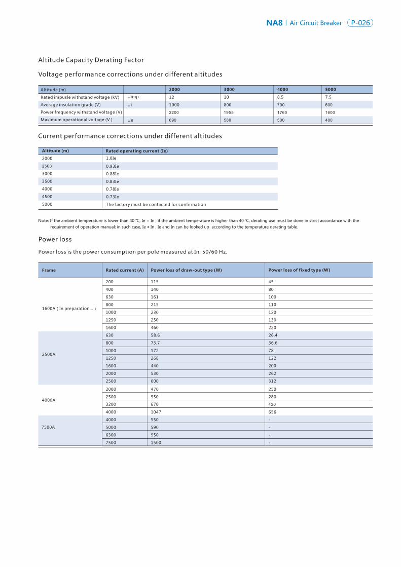
NA8 Air Circuit Breaker P-026P-025 NA8Air Circuit Breaker
Capacticy Derating and Power Loss
NA8-1600 (In preparation...)
Connection mode
40°
45°
50°
55°
60°
400A 630A 800A 1000A 1250A 1600A
Horizontal Vertical Horizontal Vertical Horizontal Vertical Horizontal Vertical Horizontal Vertical Horizontal Vertical
NA8-2500
630A 800A 1000A 1250A 1600A 2000A
NA8-4000
NA8-7500
4000A 5000A 6300A
Connection mode
40°
45°
50°
55°
60°
Horizontal Horizontal Horizontal Vertical Horizontal Vertical Horizontal Vertical Horizontal Vertical
Ambient temperature
Connection mode
Connection mode
40°
40°
45°
45°
50°
50°
55°
55°
60°
60°
Horizontal Vertical Horizontal Vertical Horizontal Vertical
-
-
-
-
-
-
-
-
-
-
-
-
-
-
550
-
-
-
-
580
-
-
-
-
700
-
-
-
-
700
-
-
-
950
900
-
-
-
950
900
-
-
-
1150
1050
-
-
-
1200
1100
-
1550
1500
1450
1350
-
-
1550
1500
1450
-
-
-
-
-
-
-
-
-
-
-
-
-
-
-
-
-
-
-
-
-
-
-
-
-
-
-
-
-
-
-
-
-
-
-
-
-
-
-
-
-
-
1500
1400
1300
-
-
1550
1450
1350
-
1900
1850
1800
1700
-
-
1900
1800
1700
-
-
-
3900
3800
-
-
-
3900
3800
-
-
4700
4600
4400
-
-
4800
4650
4500
/
/
/
/
/
-
6100
6000
5500
5200
Note: “-” represents no derating; “/” means no horizontal connection.
200A
Horizontal Vertical
-
-
-
-
-
-
-
-
-
-
2500A
Horizontal Vertical
-
2400
2300
2200
2100
-
2400
2300
2200
2100
3200A 4000A
Horizontal Vertical Horizontal Vertical
-
-
3100
3000
2900
-
-
-
3050
2950
-
3800
3600
3400
3200
-
3850
3650
3450
3250
2500A
Horizontal Vertical
-
-
-
2450
2350
-
-
-
-
2400
2000A
Horizontal Vertical
-
-
-
-
1900
-
-
-
-
1950
7500A
Horizontal Vertical
/
/
/
/
/
-
7000
6550
6050
5650
Altitude Capacity Derating Factor
Power loss
Power loss is the power consumption per pole measured at In, 50/60 Hz.
Frame
1600A(In preparation...)
2500A
4000A
Rated current (A)
400
200
630
800
1000
1250
1600
630
800
1000
1250
1600
2000
2500
2000
4000
4000
3200
2500
5000
7500
6300
Power loss of draw-out type (W) Power loss of fixed type (W)
140
115
161
215
230
250
460
470
550
670
1047
58.6
73.7
172
268
440
530
600
7500A
550
590
950
1500
80
45
100
110
120
130
220
26.4
36.6
78
122
200
262
312
250
280
656
420
-
-
-
-
Altitude (m)
2000
2500
3000
3500
4000
4500
5000
2000
Rated operating current (Ie)
3000 4000 5000
Uimp
1.0Ie
Ui
0.93Ie
0.88Ie
0.83Ie
0.78Ie
0.73Ie
The factory must be contacted for confirmation
Ue
Voltage performance corrections under different altitudes
Current performance corrections under different altitudes
12
1000
2200
690
10
800
1955
580
8.5
700
1760
500
7.5
600
1600
400
Ambient temperature
Ambient temperature
Ambient temperature
Vertical
Vertical Vertical
Altitude (m)
Rated impusle withstand voltage (kV)
Average insulation grade (V)
Power frequency withstand voltage (V)
Maximum operational voltage (V )
Note: If the ambient temperature is lower than 40 ℃, Ie = In ; if the ambient temperature is higher than 40 ℃, derating use must be done in strict accordance with the requirement of operation manual; in such case, Ie ≠ In , Ie and In can be looked up according to the temperature derating table.1600A
Horizontal Vertical
-
-
-
-
-
-
-
-
- -
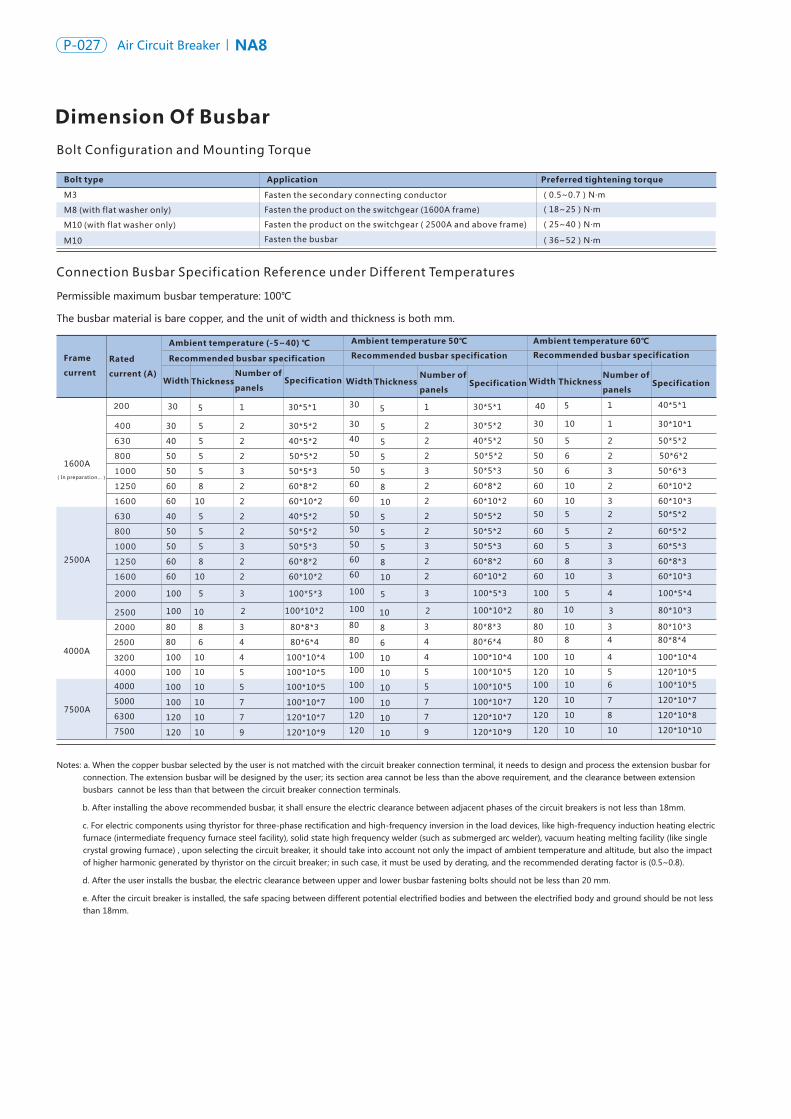
NA8 Air Circuit Breaker P-028P-027 NA8Air Circuit Breaker
Connection Busbar Specification Reference under Different Temperatures
Bolt Configuration and Mounting Torque
Dimension Of Busbar
Frame
current
1600A
2500A
4000A
Rated
current (A)
400
200
630
800
1000
1250
1600
630
800
1000
1250
1600
2000
25002000
2500
32004000
Ambient temperature (-5~40) ℃ Ambient temperature 50℃ Ambient temperature 60℃
Recommended busbar specification Recommended busbar specification Recommended busbar specification
Width Thickness Number of
panels Specification
Bolt type
M3
M8 (with flat washer only)
M10
M10
Application Preferred tightening torque
(0.5~0.7)N m·
(18~25)N·m
(25~40)N·m
(36~52)N·m
30 30 30
30 30 40
40 40 50
50 50 50
50 50 50
60 60 60
60 60 60
40 50 50
50 50 60
50 50 60
60 60 60
60 60 60
100 100 100
100 100 80
80 80 80
80 80 80
100 100 100
100 100 120
100 100 100
100 100 120
120 120 120
120 120 120
5 5 10
5 5 5
5 5 5
5 5 6
5 5 6
8 8 10
10 10 10
5 5 5
5 5 5
5 5 5
8 8 8
10 10 10
5 5 5
10 10 10
8 8 10
6 6 8
10 10 10
10 10 10
10 10 10
10 10 10
10 10 10
10 10 10
2 2 1
1 1 1
2 2 2
2 2 2
3 3 3
2 2 2
2 2 3
2 2 2
2 2 2
3 3 3
2 2 3
2 2 3
3 3 4
2 2 3
3 3 3
4 4 4
4 4 4
5 5 5
5 5 6
7 7 7
7 7 8
9 9 10
30*5*2 30*5*2 30*10*1
30*5*1 30*5*1 40*5*1
40*5*2 40*5*2 50*5*2
50*5*2 50*5*2 50*6*2
50*5*3 50*5*3 50*6*3
60*8*2 60*8*2 60*10*2
60*10*2 60*10*2 60*10*3
40*5*2 50*5*2 50*5*2
50*5*2 50*5*2 60*5*2
50*5*3 50*5*3 60*5*3
60*8*2 60*8*2 60*8*3
60*10*2 60*10*2 60*10*3
100*5*3 100*5*3 100*5*4
100*10*2 100*10*2 80*10*3
80*8*3 80*8*3 80*10*3
80*6*4 80*6*4 80*8*4
100*10*4 100*10*4 100*10*4
100*10*5 100*10*5 120*10*5
100*10*5 100*10*5 100*10*5
100*10*7 100*10*7 120*10*7
120*10*7 120*10*7 120*10*8
120*10*9 120*10*9 120*10*10
7500A
4000
5000
6300
7500
(with flat washer only)
NA8-1600 draw-out type
Hole size
Hole size of the base
Front view Side view
Dimension And Installation
210
141( 3P )
351
141211( 4P )
36
7595
350(connected position)
394(disconnected position)
310
275
Pole N
6.5
9575
78
10
67(3P)137(4P)
Datum line
2×Φ8.5
220
32
0
10×Φ5
11
81
20
11
8
258
Hole size of the panel
Datum line
Circuit breaker mounting plate
2
Fasten the secondary connecting conductor
Fasten the product on the switchgear (1600A frame)
Fasten the product on the switchgear ( 2500A and above frame)
Fasten the busbar
Permissible maximum busbar temperature: 100℃
The busbar material is bare copper, and the unit of width and thickness is both mm.
Notes: a. When the copper busbar selected by the user is not matched with the circuit breaker connection terminal, it needs to design and process the extension busbar for connection. The extension busbar will be designed by the user; its section area cannot be less than the above requirement, and the clearance between extension busbars cannot be less than that between the circuit breaker connection terminals.
b. After installing the above recommended busbar, it shall ensure the electric clearance between adjacent phases of the circuit breakers is not less than 18mm.
c. For electric components using thyristor for three-phase rectification and high-frequency inversion in the load devices, like high-frequency induction heating electric furnace (intermediate frequency furnace steel facility), solid state high frequency welder (such as submerged arc welder), vacuum heating melting facility (like single crystal growing furnace) , upon selecting the circuit breaker, it should take into account not only the impact of ambient temperature and altitude, but also the impact of higher harmonic generated by thyristor on the circuit breaker; in such case, it must be used by derating, and the recommended derating factor is (0.5~0.8).
d. After the user installs the busbar, the electric clearance between upper and lower busbar fastening bolts should not be less than 20 mm.
e. After the circuit breaker is installed, the safe spacing between different potential electrified bodies and between the electrified body and ground should be not less than 18mm.
Width Thickness Number of
panels Specification Width Thickness
Number of
panels Specification
(In preparation...)
(In preparation...)
Datum line
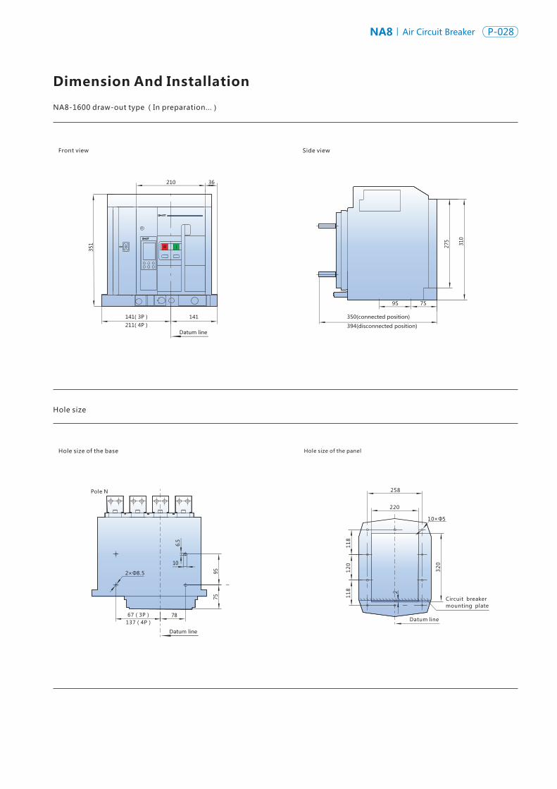
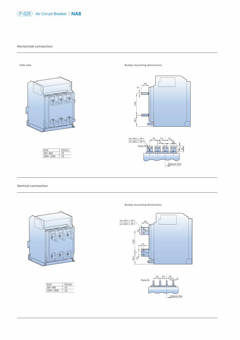
NA8 Air Circuit Breaker P-030P-029 NA8Air Circuit Breaker
Busbar mounting dimensions
Horizontal connection
Side view Busbar mounting dimensions
150
78.5
D
50
16×Φ11(4P)12×Φ11(3P)
15
25
15
078
.5
50
50
Vertical connection
16
16
Datum line
Datum line
70 70 70D
Four-pole product horizontal extension busbar (optional)
Side view
Side view
Busbar mounting dimensions
Busbar mounting dimensions
90
AB
C
D
90
AB
C
D
16
16
101
35
90
12
0
101
20 80 35 15
24×Φ11
Datum line
101 101 101
20 80 35
35
90
12
0
15
15.5
Datum line
32×Φ11
12×Φ11(3P)16×Φ11(4P)
Pole N
Three-pole product horizontal extension busbar (optional)
Unit: mm
Note: The extension busbar is of optional accessory, requiring additional expense.
Pole NUnit: mm
Note: The extension busbar is of optional accessory, requiring additional expense.
Pole N
63
63
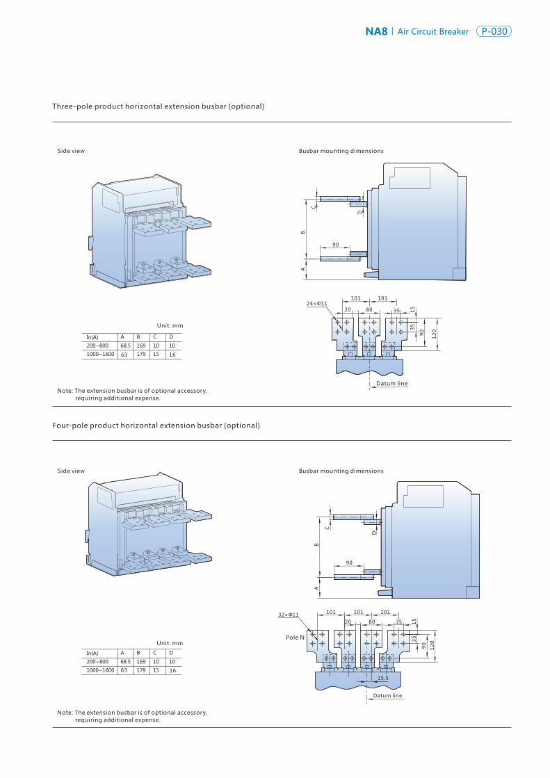
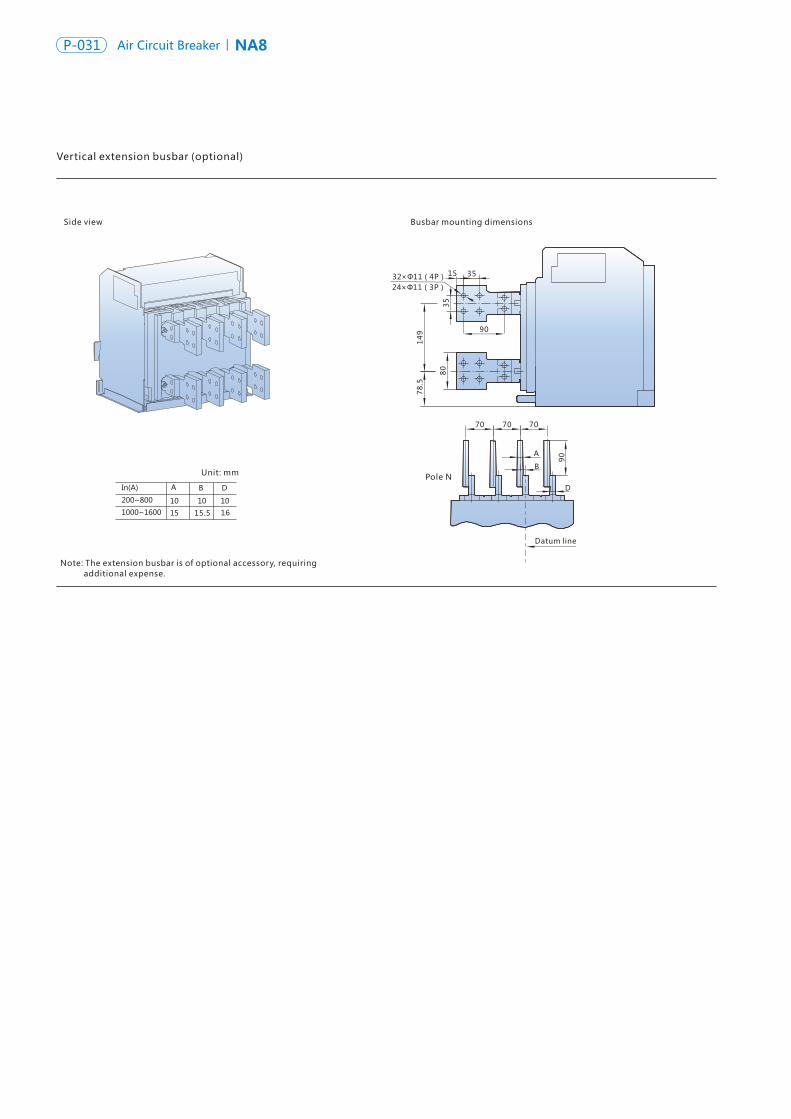
NA8 Air Circuit Breaker P-032P-031 NA8Air Circuit Breaker
Vertical extension busbar (optional)
Side view Busbar mounting dimensions
90
15 35
35
14
9
24×Φ11(3P)32×Φ11(4P)
78
.5
80
15.5 16
70 70 70
90
Datum line
B
D
A
NA8-1600 fixed type
Hole size
Front view
Hole size of the panel
Side view
100 64
210
320
27
5
118.5
127
188.5(4P)118.5(3P)
127(3P)197(4P) Datum line
250
220
188.5(4P)118.5
Datum line
118.5(3P)
4×Φ8.5
100
64 Circuit breaker mounting plate
Datum line
32
2
28
5
8×Φ5
6
Pole NUnit: mm
Hole size of the base
Note: The extension busbar is of optional accessory, requiring additional expense.
(In preparation...)
258
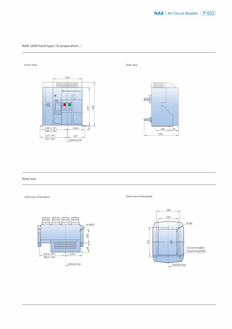
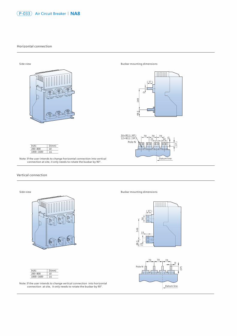
NA8 Air Circuit Breaker P-034P-033 NA8Air Circuit Breaker
Vertical connection
Side view Busbar mounting dimensions
Horizontal connection
Side view Busbar mounting dimensions
(37)
149
48.5
D
149
(37)
48.
5
50
15
25
16
16
16×Φ11(4P)12×Φ11(3P)
Side view
Side view
Busbar mounting dimensions
Busbar mounting dimensions
A
90
D
C
B
BA
C
D
90
16
16
70 70 70
(3
7)
25 50 15
Datum line
Datum line
70 70 70D
Datum line
Datum line
24×Φ11 101 101
20 80 35 15
35
90
12
0
32×Φ11 101
80
101 101
20 35
12
0
35
901
5
15.5
Pole N
Note: If the user intends to change horizontal connection into vertical connection at site, it only needs to rotate the busbar by 90°.
Pole N
Note: If the user intends to change vertical connection into horizontal connection at site, it only needs to rotate the busbar by 90°.
Three-pole product horizontal extension busbar connection (optional)
Pole N
Four-pole product horizontal extension busbar connection (optional)
Note: The extension busbar is of optional accessory, requiring additional expense.
Note: The extension busbar is of optional accessory, requiring additional expense.
Unit: mm
Unit: mm
33
33
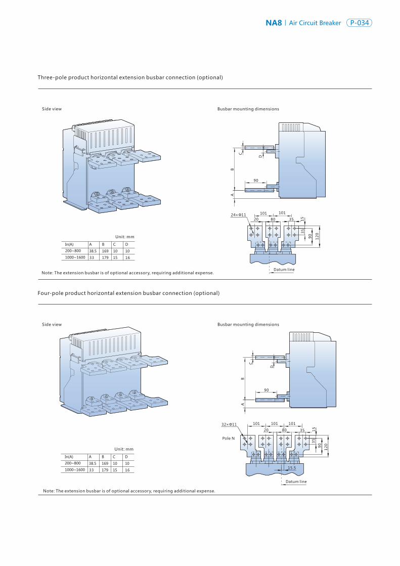
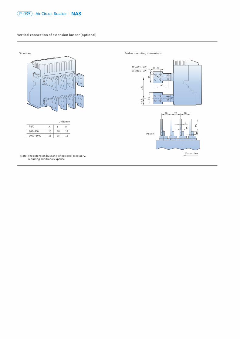
NA8 Air Circuit Breaker P-036P-035 NA8Air Circuit Breaker
Side view Busbar mounting dimensions
32×Φ11(4P)
24×Φ11(3P)15 35
15
0 90
35
48
.5 80
16
70
Datum line
B
A
70 70
90
D
NA8-2500 Draw-out type
284
187.5187.5(3P)282.5(4P)
Datum line
12
9
15
0
20
02
31
.5
19
5.5
12
9
406
108
98
Hole size
Hole size of the base Hole size of the panel
Datum line
11×Φ5
344
378
147
47
155
268
20
21.5
2×Φ11
11×17
132( 3P ) 227.5( 4P )
132
Datum line
175
98
108
Vertical connection of extension busbar (optional)
Unit: mm
Pole N
Note: The extension busbar is of optional accessory, requiring additional expense.
Front view Side view
Pole N
Circuit breaker mounting base plate
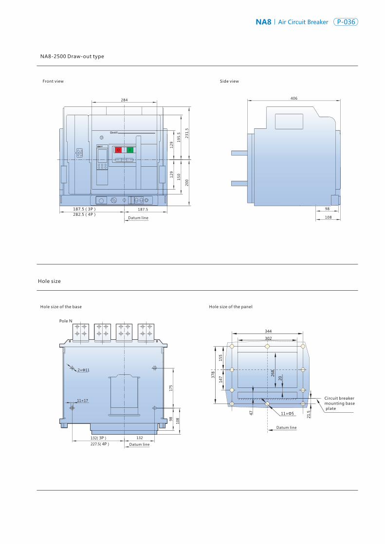
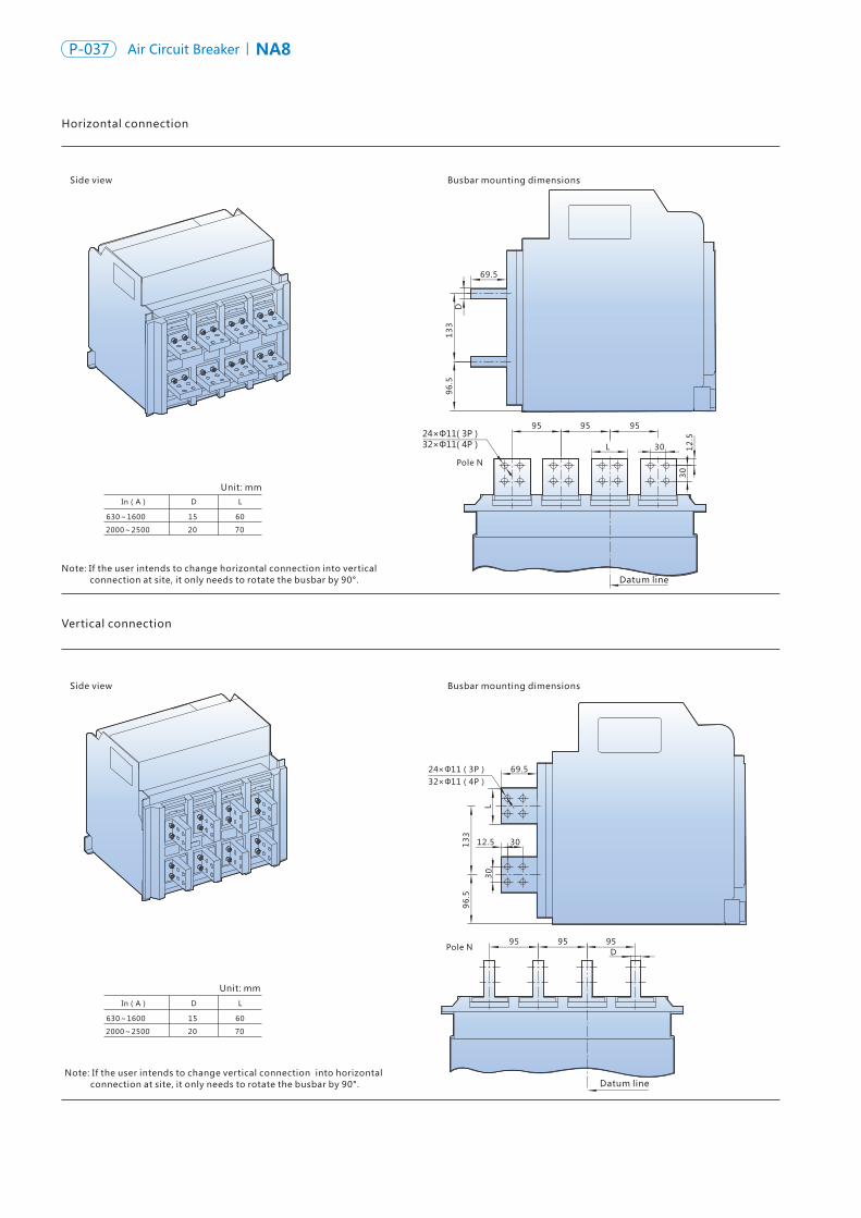
NA8 Air Circuit Breaker P-038P-037 NA8Air Circuit Breaker
Horizontal connection
Side view
Side view
Busbar mounting dimensions
Busbar mounting dimensions
In(A) D L
630~1600 15 60
2000~2500 20 70
In(A) D L
630~1600 15 60
2000~2500 20 70
Note: If the user intends to change horizontal connection into vertical connection at site, it only needs to rotate the busbar by 90°.
Datum line
24×Φ11(3P)
13
39
6.5
D
69.5
133
96
.5
32×Φ11(4P)
12.5 30
L30
95 95 95
L 30
30
12
.524×Φ11( 3P ) 32×Φ11( 4P )
95 95 95D
69.5
Hole size
NA8-2500 fixed type
Hole size of the base
Front view
Hole size of the panel
Side view
Datum line
8×Φ6
300342
269
311
Circuit breaker mounting base plate
29.521
.5
284
185( 3P )280( 4P )
185
232.
516
3.5
195.
515
0129
129
307
85
26.5
Pole N
150
16
12170( 3 P )285( 4 P )
170
Datum line
87
26.5
Datum line
Datum line
Unit: mm
Vertical connection
Pole N
Unit: mm
Note: If the user intends to change vertical connection into horizontal connection at site, it only needs to rotate the busbar by 90°.
Pole N
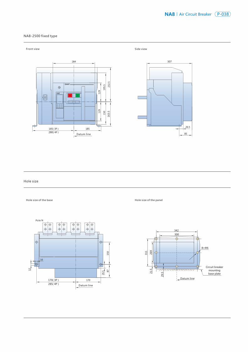
NA8 Air Circuit Breaker P-038P-037 NA8Air Circuit Breaker
Horizontal connection
Side view
Side view
Busbar mounting dimensions
Busbar mounting dimensions
In(A) D L
630~1600 15 60
2000~2500 20 70
In(A) D L
630~1600 15 60
2000~2500 20 70
Note: If the user intends to change horizontal connection into vertical connection at site, it only needs to rotate the busbar by 90°.
Datum line
24×Φ11(3P)
13
39
6.5
D
69.5
133
96
.5
32×Φ11(4P)
12.5 30
L30
95 95 95
L 30
30
12
.524×Φ11( 3P ) 32×Φ11( 4P )
95 95 95D
69.5
Hole size
NA8-2500 fixed type
Hole size of the base
Front view
Hole size of the panel
Side view
Datum line
8×Φ6
300342
269
311
Circuit breaker mounting base plate
29.521
.5
284
185( 3P )280( 4P )
185
232.
516
3.5
195.
515
0129
129
307
85
26.5
Pole N
150
16
12
170( 3 P )285( 4 P )
170
Datum line
87
26.5
Datum line
Datum line
Unit: mm
Vertical connection
Pole N
Unit: mm
Note: If the user intends to change vertical connection into horizontal connection at site, it only needs to rotate the busbar by 90°.
Pole N
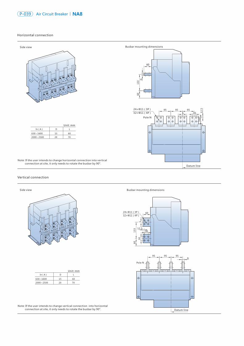
NA8 Air Circuit Breaker P-040P-039 NA8Air Circuit Breaker
Vertical connection
Side view
Side view
Busbar mounting dimensions
Busbar mounting dimensions
In(A) D L
630~1600 15 60
2000~2500 20 70
In(A) D L
Unit: mm
630~1600 15 60
2000~2500 20 70
60
D13
360
95 95 95L 30
30
12
.5
Datum line
24×Φ11(3P)32×Φ11(4P)
95 95 95D
Pole N
Datum line
32×Φ11(4P)24×Φ11(3P) 60
L
13
36
0
3012.5
30
Horizontal connection
Unit: mm
Note: If the user intends to change horizontal connection into vertical connection at site, it only needs to rotate the busbar by 90°.
Pole N
Note: If the user intends to change vertical connection into horizontal connection at site, it only needs to rotate the busbar by 90°.
Hole size
NA8-4000 draw-out type
Hole size of the base
Front view
Hole size of the panel
Side view
Datum line
11×Φ5
371
328
376
145
47
155
268
20
21.5
Circuit breaker mounting base plate
308
431
Datum line
199
232
217.5(3P)332.5(4P)
217.5
258
407(connected position)
454(disconnected position)
42
Φ14
Pole N
17
5
11
162.5162.5(3P)277.5(4P)
Datum line
17
10
8
10898
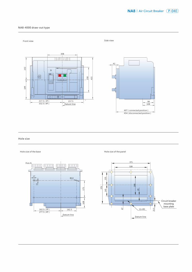
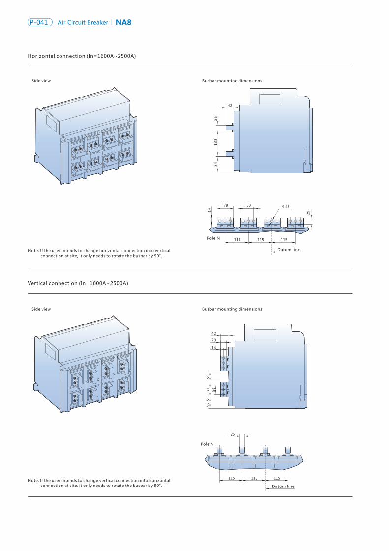
NA8 Air Circuit Breaker P-042P-041 NA8Air Circuit Breaker
Horizontal connection (In=1600A~2500A)
Vertical connection (In=1600A~2500A)
Side view
Side view
Busbar mounting dimensions
Busbar mounting dimensions
Datum line
Datum line
25
42
13
38
4
42
55
29
14
78
50
57
.5
Horizontal connection (In=3200A~4000A)
Vertical connection (In=3200A~ 4000A)
Side view
Side view
Busbar mounting dimensions
Busbar mounting dimensions
Datum line
Datum line
42
2584
13
3
42
29
14
Φ11
75 25
573
5.5
10
0
115
25
115 115
Pole N
Note: If the user intends to change horizontal connection into vertical connection at site, it only needs to rotate the busbar by 90°.
Note: If the user intends to change vertical connection into horizontal connection at site, it only needs to rotate the busbar by 90°.
Note: If the user intends to change horizontal connection into vertical connection at site, it needs to change the upper and lower busbars of phases N and B into the same busbars of phases A and C.
Pole N
Note: If the user intends to change vertical connection into horizontal connection at site, it needs to change the upper and lower busbars of phases N and B into the same busbars of phases A and C.
Pole N
Pole N
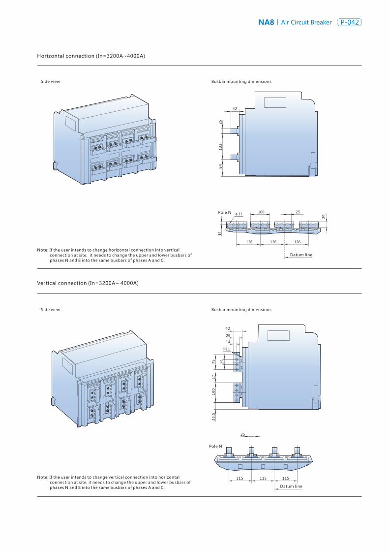
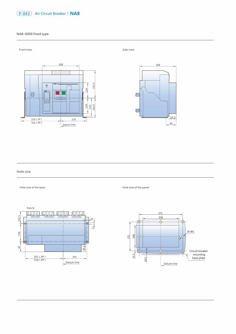
NA8 Air Circuit Breaker P-044P-043 NA8Air Circuit Breaker
Hole size
Hole size of the base
Front view
Hole size of the panel
Side view
8×Φ5
328
371
268
311
Circuit breaker mounting base plate
29.521
.5
308
216331(4P)216(3P)
Datum line
308
58.5
85
16
201(3P)316(4P)
Datum line
Pole N
201
12
58
.5851
02
.515
0
Vertical connection (In=1600A~2500A)
Side view Busbar mounting dimensions
Datum line
Pole N
50
55
78
21
33
29
1418×Φ11(3P)24×Φ11(4P)
Side view Busbar mounting dimensions
Datum line
Pole N
13
34
7.5
25
33
12
91
29
15
0
16
3.5
23
2.5
Datum line
NA8-4000 fixed type Horizontal connection (In=1600A~2500A)
Note: If the user intends to change horizontal connection into vertical connection at site, it only needs to rotate the busbar by 90°.
Note: If the user intends to change vertical connection into horizontal connection at site, it only needs to rotate the busbar by 90°.
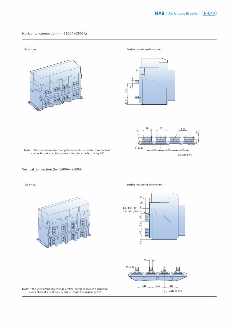
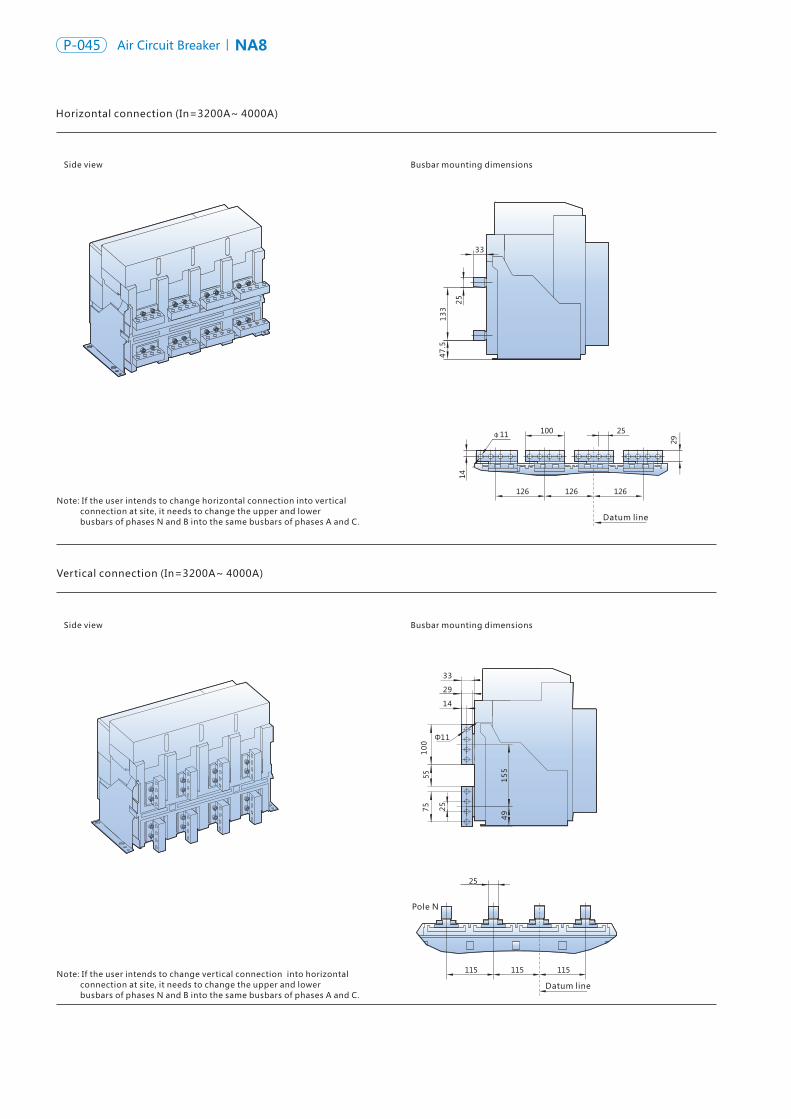
NA8 Air Circuit Breaker P-046P-045 NA8Air Circuit Breaker
Side view
Side view
Busbar mounting dimensions
Busbar mounting dimensions
Pole N
13
34
7.5
25
33
33
29
14
10
055
75
15
54
925
Φ11
Hole size
NA8-7500 (In=4000A~ 6300A) three-pole draw-out type
Hole size of the base
Front view
Hole size of the panel
Side view
15
5
15
11
Datum line
20
79
2
677
197
156 240
450.5335.5
25
8
23
12
00
.54
0
11×Φ5
371
328
378
145
155
268
20
21.5
42
Circuit breaker mounting base plate
47
384.5
464(connected position)510(disconnected position)
56.5
308
Horizontal connection (In=3200A~ 4000A)
Datum line
Datum line
Datum line
Datum line
Note: If the user intends to change horizontal connection into vertical connection at site, it needs to change the upper and lower busbars of phases N and B into the same busbars of phases A and C.
Vertical connection (In=3200A~ 4000A)
Note: If the user intends to change vertical connection into horizontal connection at site, it needs to change the upper and lower busbars of phases N and B into the same busbars of phases A and C.
92207
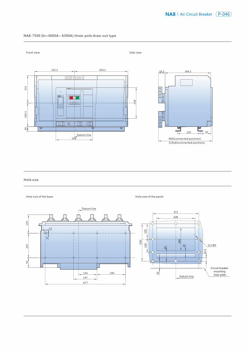
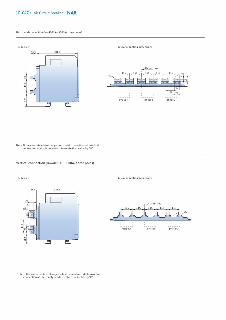
NA8 Air Circuit Breaker P-048P-047 NA8Air Circuit Breaker
Horizontal connection (In=4000A~ 5000A/ three poles)
Vertical connection (In=4000A~ 5000A/ three poles)
Side view
Side view
Busbar mounting dimensions
Busbar mounting dimensions
384.5
98
.57
8 39
50
13
3
56.5
29
14
384.5
12
51
33
25
56.5
Datum line
Φ11
Datum line
115115 115 115 11525 1
4
37
50
29
78
Φ11
Vertical connection (In=6300A/ three poles)
Side view Busbar mounting dimensions
Φ11
384.5
35
47
.56
84
7.5
25
25×
3=
75
13
5
56.5
2914
Datum line
phaseBPhase A phaseC
phaseBPhase A phaseC
phaseBPhase A phaseC
Note: If the user intends to change horizontal connection into vertical connection at site, it only needs to rotate the busbar by 90°.
Note: If the user intends to change vertical connection into horizontal connection at site, it only needs to rotate the busbar by 90°.
Note: In=6300A only has vertical connection and has no horizontal connection.
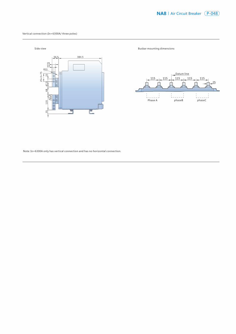
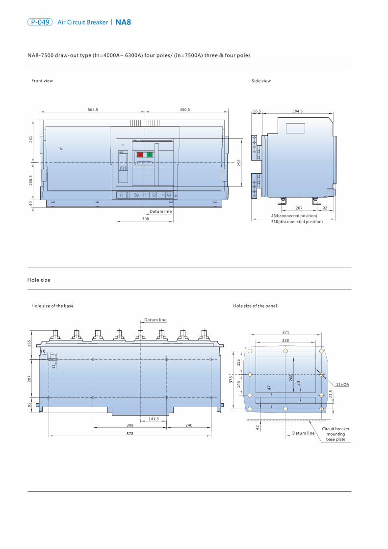
NA8 Air Circuit Breaker P-050P-049 NA8Air Circuit Breaker
Hole size
Hole size of the base
Front view
Hole size of the panel
Side view
15
5
15
11
Datum line
20
79
2
878
398
141.5
240
450.5565.5
308
25
8
23
12
00
.54
0
Datum line
Datum line
11×Φ5
371
328
378
145
155
268
20
21.5
42 Circuit breaker mounting base plate
47
384.5
464(connected position)
510(disconnected position)
56.5
N
Horizontal connection (In=4000A ~ 5000A/ four poles)
Side view
Side view
Busbar mounting dimensions
Busbar mounting dimensions
384.5
98
.57
8 39
50
13
3
56.5
2914
384.5
12
51
33
25
115
Datum line
78
50
25
37
14
29
Φ11115115115115115115
Phase A Phase B Phase C Phase N
115
Datum line
115115115115115115
56.5
25Φ11
NA8-7500 draw-out type (In=4000A~ 6300A) four poles/ (In=7500A) three & four poles
Phase A Phase B Phase C Phase N
Note: If the user intends to change horizontal connection into vertical connection at site, it only needs to rotate the busbar by 90°.
Vertical connection (In=4000A~ 5000A/ four poles)
Note: If the user intends to change vertical connection into horizontal connection at site, it only needs to rotate the busbar by 90°.
207 92
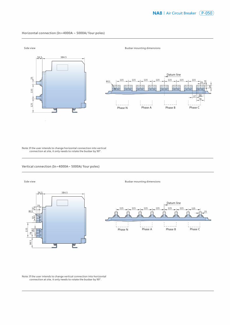
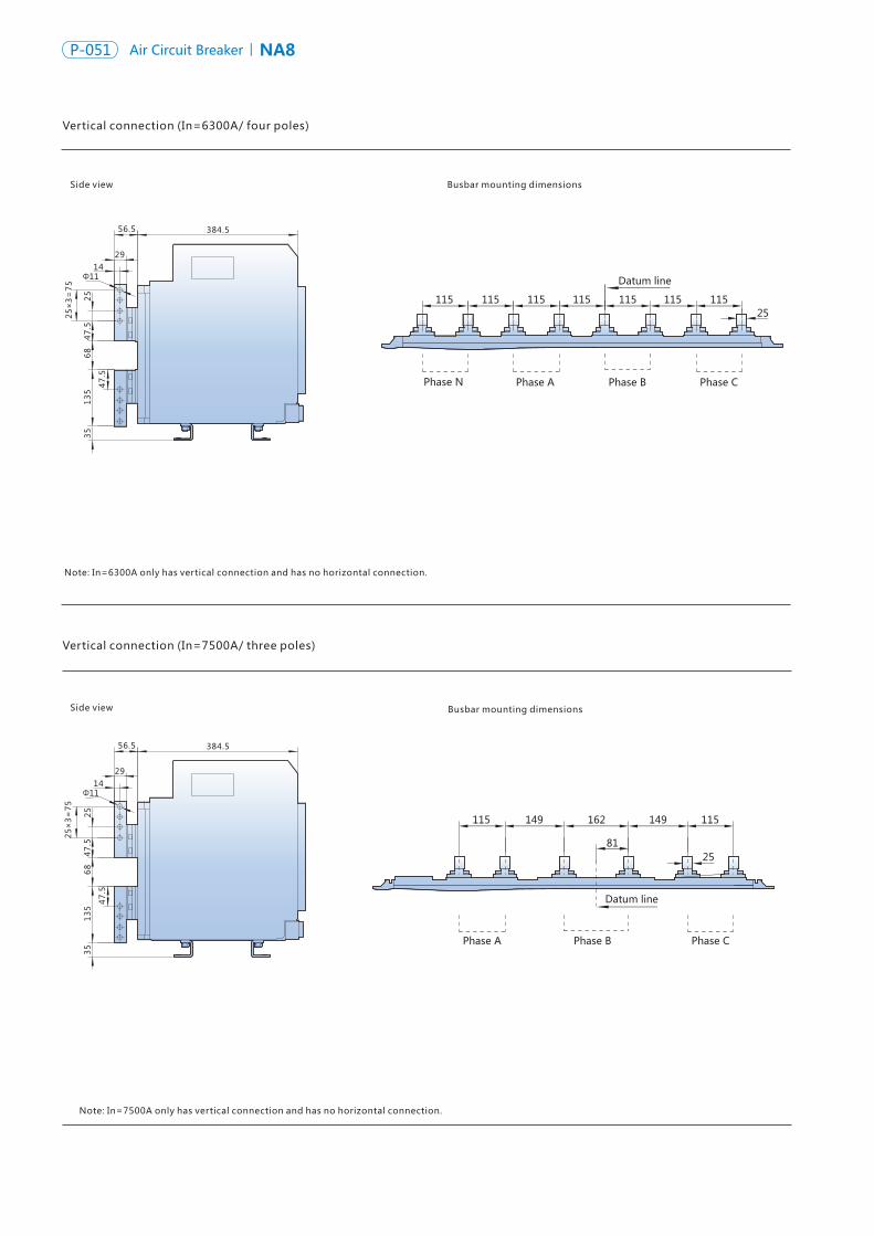
NA8 Air Circuit Breaker P-052P-051 NA8Air Circuit Breaker
Vertical connection (In=7500A/ three poles)
Vertical connection (In=6300A/ four poles)
Side view
Side view
Busbar mounting dimensions
Busbar mounting dimensions
E
Note: In=7500A only has vertical connection and has no horizontal connection.
Φ11
384.5
35
47
.5
68
47
.52
5
25×
3=
75
13
5
56.5
2914
Phase A Phase B Phase CPhase N
115
Datum line
11511511511525
115115
Datum line
25
115149162149115
81
Φ11
384.5
35
47
.5
68
47
.52
51
35
56.5
2914
25×
3=
75
Vertical connection (In=7500A/ four poles)
Side view Busbar mounting dimensions
Datum line
25
115149162149115
81
115
56.5 384.5
2914
Φ11
47
.54
7.5
25
68
13
53
5
25×
3=
75
Dimensions of undervoltage time delay control module, power module, RU-1 relay signal module
Note: Undervoltage time delay control module, power module, RU-1 relay signal module have consistent overall dimensions, and can be installed using the 35mm standard DIN rail mounting.
72
60.5
90
82
Φ4.5
39 8
24
.5
45
35
.5
1.5
2.5
4
53
Note: In=6300A only has vertical connection and has no horizontal connection.
Phase A Phase B Phase C
Phase A Phase B Phase CPhase N
Note: In=7500A only has vertical connection and has no horizontal connection.
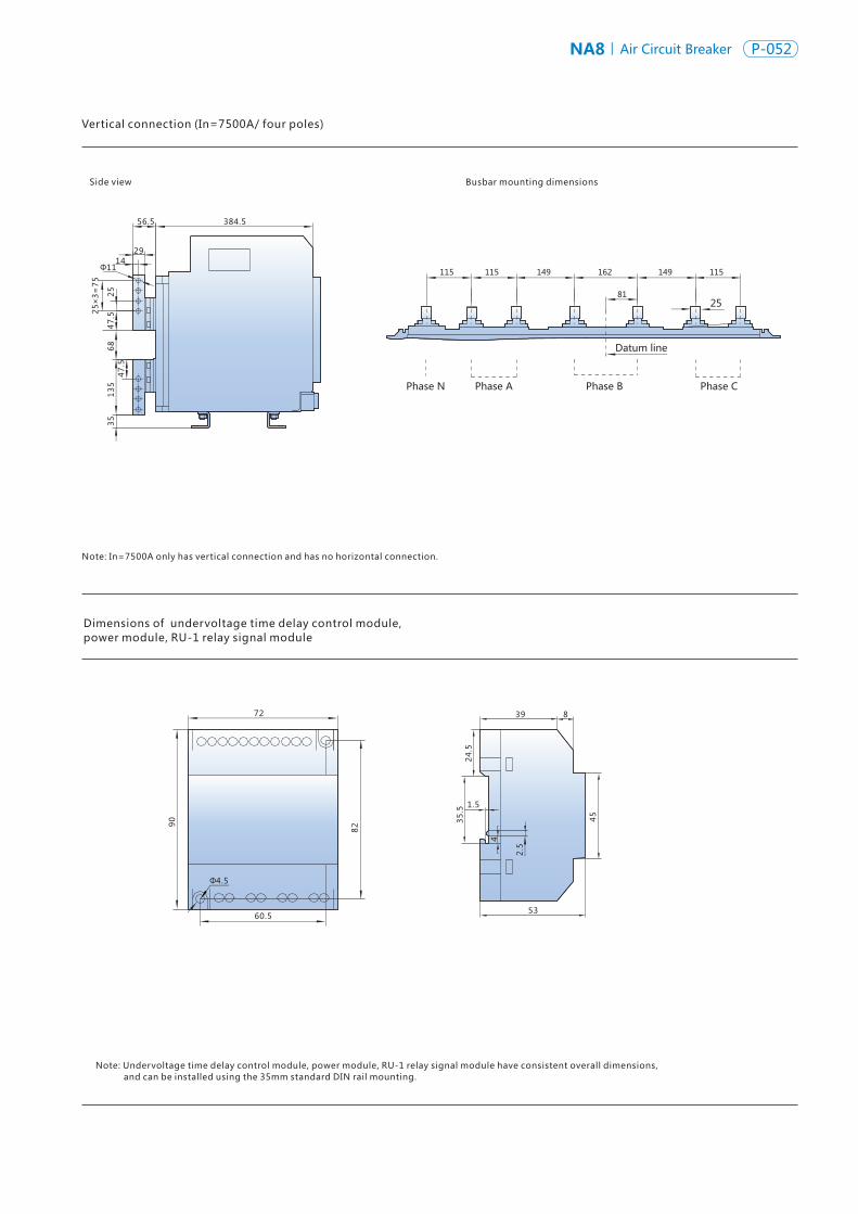
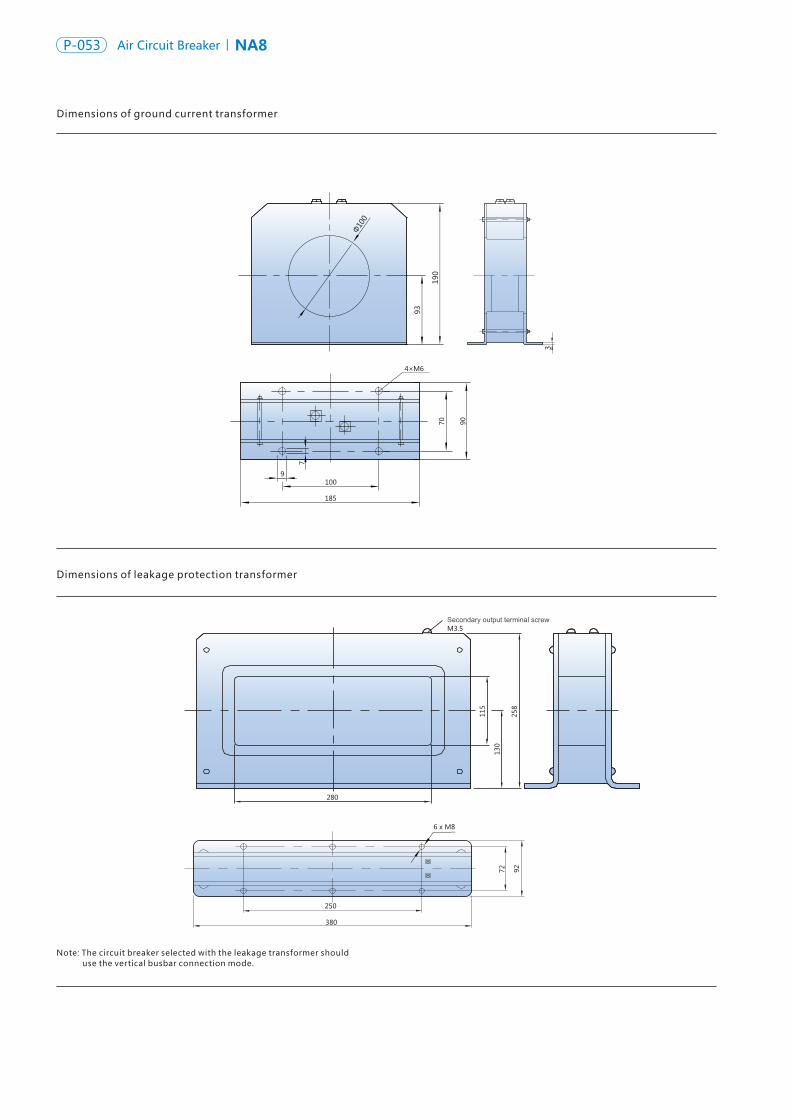
NA8 Air Circuit Breaker P-054P-053 NA8Air Circuit Breaker
E
Note: The circuit breaker selected with the leakage transformer should use the vertical busbar connection mode.
9272
Secondary output terminal screw
250
380
280
115
130
258
M3.5
6 x M81
9100
4×M6
185
7
70 90
190
3
93
Φ10
0
Dimensions of ground current transformer
Dimensions of leakage protection transformer
12
8
6
21.5
39
.5
144
Dimensions of neutral pole current transformer
Front view
Flexible connection coil
Main circuit entry
Upper entry Main circuit entry
Bottom entry
Main circuit entry direction
Main circuit entry direction
21
.5
Note: 1. Upon fixing the neutral transformer, it needs to install it at the entry end of circuit breaker, and one side of its flexible cable should face the entry direction of main circuit. 2.When the rated current is 200A-630A, the transformer needs to be wrapped around the busbar twice to be used normally.
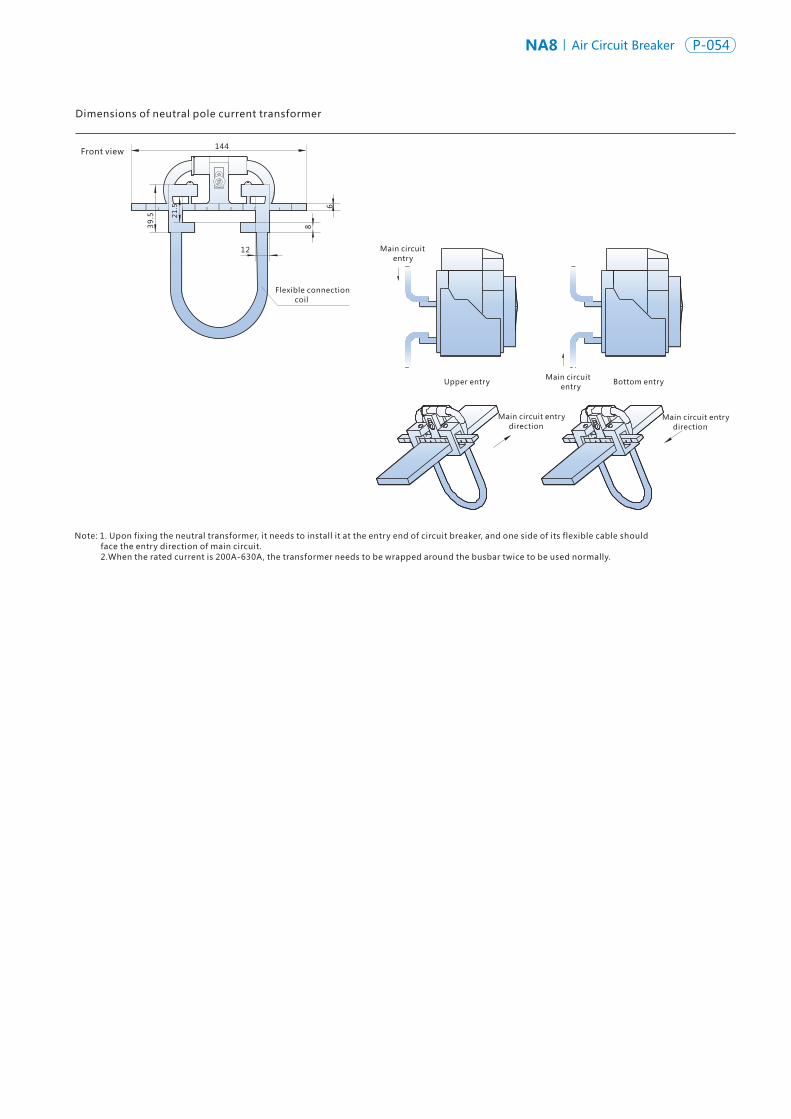
NA8 Air Circuit Breaker P-054P-053 NA8Air Circuit Breaker
E
Note: The circuit breaker selected with the leakage transformer should use the vertical busbar connection mode.
9272
Secondary output terminal screw
250
380
280
115
130
258
M3.5
6 x M81
9100
4×M6
185
7
70 90
190
3
93
Φ10
0
Dimensions of ground current transformer
Dimensions of leakage protection transformer
12
8
6
21.5
39
.5144
Dimensions of neutral pole current transformer
Front view
Flexible connection coil
Main circuit entry
Upper entry Main circuit entry
Bottom entry
Main circuit entry direction
Main circuit entry direction
21
.5
Note: 1. Upon fixing the neutral transformer, it needs to install it at the entry end of circuit breaker, and one side of its flexible cable should face the entry direction of main circuit. 2.When the rated current is 200A-630A, the transformer needs to be wrapped around the busbar twice to be used normally.
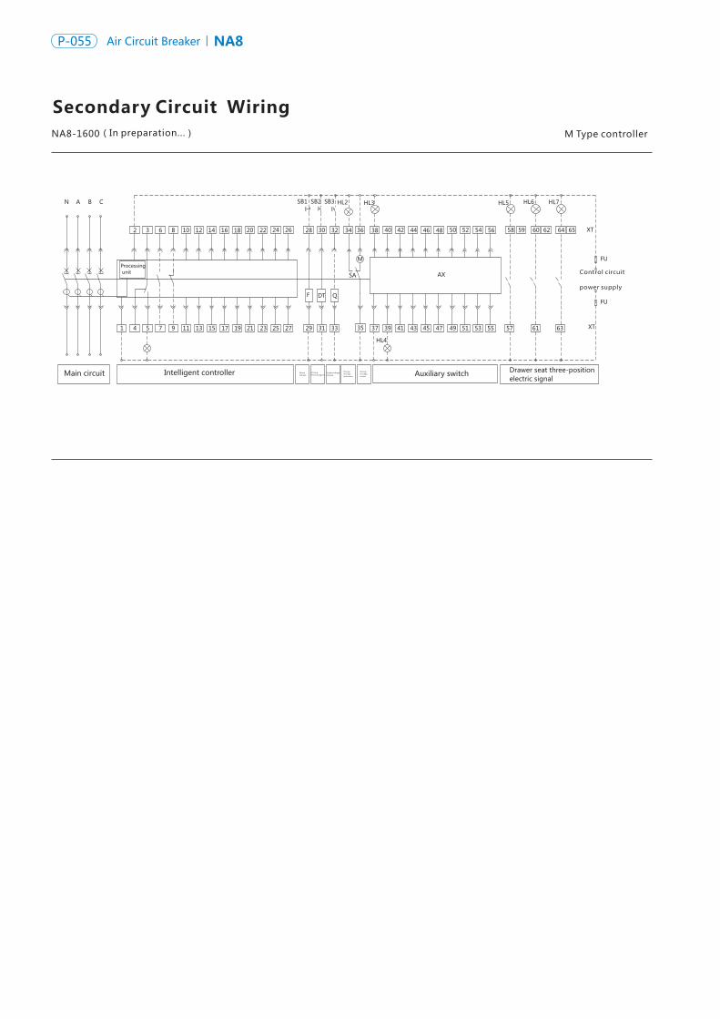
NA8 Air Circuit Breaker P-056P-055 NA8Air Circuit Breaker
Secondary Circuit Wiring M Type controllerNA8-1600 Used by the user
C 04 four groups of changeover contacts (default)
C 06 six groups of changeover contacts (optional)
N 3 3 NO 3 NC contacts (optional)
Type of AX auxiliary contact
37
38 39
40
41 42
43
44 45
46
47 48
37
38 39
40
41 42
43
44 45
46
47 48
49
50 51 53 54
52 37
38
39 43 45 47
40 42 44 48 46
41
22 24 26 28 30 32 36 38
SB2
5 7 9 11 19
44 46 4842
Auxiliary switch Drawer seat three-position electric signal
SB1
Main circuit Intelligent controller
A B CN
Processing unit
632 18
FU
XT
1715134
40 50 52 56 58 60 6459 62 6554208 10 14
1
SB3
25 272321 29 31 33
34
35 37 39 41 43 45 47 49 51 53 55 57 61 63
SA
F DT Q
M
AX
HL2 HL3 HL5 HL6 HL7
HL4
XT
FU
12 16
Control circuit power supply
Shunt release
Clos ingelectromagnet
Undervoltagerelease
Energy storageindication
Energystorage motor
F—Shunt release DT—Closing electromagnet
Q—Undervoltage release
M—Motor-driven mechanism
SA—Travel switch XT—Connection terminal
AX—Auxiliary contact SB1—Breaking button
SB2—Making button SB3—Emergency stop button
HL1—Fault indicator light HL2—Energy storage indicator light
HL3—Breaking indicator light
HL4—Making indicator light
HL5 ~7 —Position indicator light
FU—Fuse (6A)
1#, 2#: Intelligent controller power supply: voltage AC220/380V can be directly connected to 1#, 2#; If voltage is DC220/110V, it needs to through the power module,and the power module outputs 24V which can be connected to 1#, 2#.
3#~5#: Tripping alarm contact (3 is the common point.)
6#~ 9#: Auxiliary contact (1 NO and 1 NC ), optional.
10#, 11#: Empty
12#~ 19#: Empty
20#: Empty
21#~24#: Empty
24#, 25#: The contacts for external phase N transformer input signal; for conventional product, they are empty, and should be ordered by the user specifically. Where external transformer is required, they are the external transformer signal input contacts.
27#:Protective grounding, is connected to the outer board of the circuit breaker;
28#, 29#: Shunt release;
30#, 31#: Closing electromagnet;
32#, 33#: Undervoltage release.
34#~36#: Motor-driven mechanism.
37#~56#: Auxiliary contact.The conventional product has 4 groups of changeover auxiliary contacts; in case of special order from the user, 6 groups of changeover contacts can be provided, 3 NO 3C contacts. 6 groups of changeover contacts are used for AC only.
57#~65#: Draw-out type circuit breaker three-position signal indication; the conventional supply has not wire connection, is only for the draw-out type circuit breaker with the secondary functions selected.
Note: The part in solid line has been connected by the factory, and the part in dashed line shall be connected by the customer.
(In preparation...)
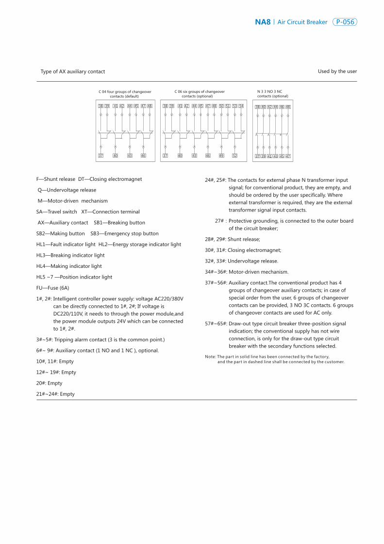
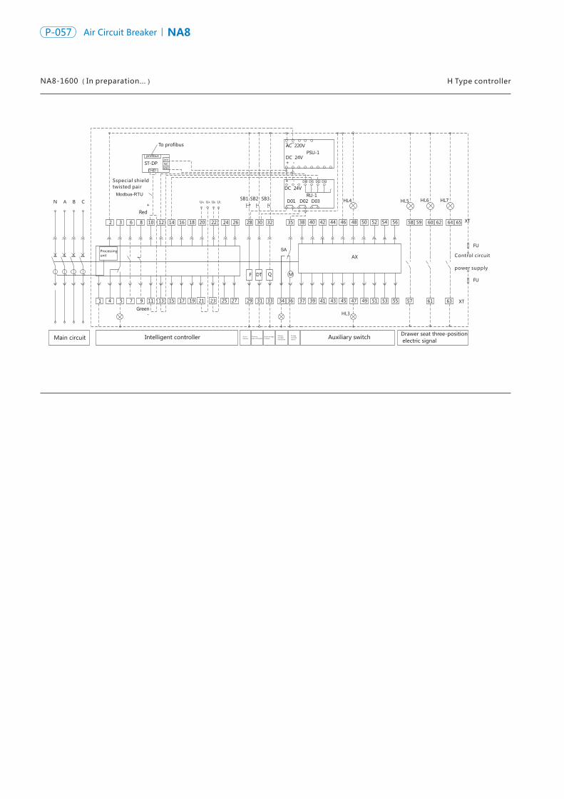
NA8 Air Circuit Breaker P-058P-057 NA8Air Circuit Breaker
H Type controllerNA8-1600 (In preparation...) Used by the user
C04 four groups of changeover contacts (default)
C06 six groups of changeover contacts (optional)
Type of AX auxiliary contact
37
38 39
40
41 42
43
44 45
46
47 48
37
38 39
40
41 42
43
44 45
46
47 48
49
50 51 53 54
52 37
38
39 43 45 47
40 42 44 48 46
41
Drawer seat three-position electric signal
58 60 6459 62 65
57 61 63
HL5HL4
HL3
HL6 HL7
To profibus
profibus 24VNCGND
D+D-
ST-DP
N A B C
2 3 6 8 10
Red +
12 14 16 18 20 22 24 26 28 30 32 35 38 40 42 44 46 48 50 52 54 56
Modbus-RTUUN A BU CU
SB2SB1 SB3
AC 220V
-+DC 24V
PSU-1
-+DC 24V
DI0 DI1 DI2 DI3
RU-1D01 D02 D03
Processing unit
SA
QF DT M
1 4 5 7 9 11
Green-
13 15 17 19 21 23 25 27 29 31 33 34 36 37 39 41 43 45 47 49 51 53 55 XT
FU
XT
FU
Auxiliary switchMain circuit Intelligent controller
AX
U
Sspecial shield twisted pair
Control circuit
power supply
Shunt release
Clos ing electromagnet
Undervoltage release
Energystorage indication
Energy storage motor
N3 3 NO 3 NC contacts (optional)
F —Shunt release DT —Closing electromagnet
Q —Undervoltage release
M —Motor-driven mechanism
SA —Travel switch XT —Connection terminal
AX —Auxiliary contact SB1 —Breaking button
SB2 —Making button SB3 —Emergency stop button
HL1 —Fault indicator light
HL2 —Energy storage indicator light
HL3 —Breaking indicator light
HL4 —Making indicator light
HL5 ~ 7 —Position indicator light
FU —Fuse (6A)
1#, 2#: Intelligent controller power supply: voltage AC220/380V can be directly connected to 1#, 2#; If voltage is DC220/110V, it needs to through the power module,and the power module outputs 24V which can be connected to 1#, 2#.
3#~5#: Tripping alarm contact (3 is the common point)
6#~9#: Auxiliary contact (1 NO and 1 NC ), optional.
10#, 11#: Type H intelligent controller default communication output contact.
12#~15#: 3 groups of programmable output signal, which must be connected with external RU-1 relay module. When type H intelligent controller has programmable output signal, default output: 12 #, 13#: Closing signal output, 12#,14 #: Opening signal output,12 #, 15 #: Fault tripping. The conventional product has no such connection.
Note: The part in solid line has been connected by the factory, and the part in dashed line shall be connected by the customer.
19#:H type intelligent controller communication shielding ground wire
20#~23#: Voltage display input signal contact,20#: Phase N voltage signal,21#: Phase A voltage signal, 22#: Phase B voltage signal,23# : Phase C voltage signal. The conventional product has no such connection.
24#, 25#: External Phase N transformer or external earth current transformer input signal contact; for conventional product, they are empty, and should be ordered by the user specifically. Where external transformer is required, they are the external transformer signal input contacts.
27#: Protective grounding, is connected to the outer board of the circuit breake;
28#, 29#: Shunt release;
30#, 31#: Closing electromagnet;
32#, 33#: Undervoltage release.
34 #~ 36 #: Motor-driven mechanism.
37 #~ 56 #: Auxiliary contact. 6 groups of changeover contacts are used for AC only.The conventional product has 4 groups of changeover auxiliary contacts; in case of special order from the user, 6 groups of changeover contacts, 3 NO 3C contacts can be provided.
57#~ 65#: Draw-out type circuit breaker three-position signal indication; the conventional supply has not wire connection, is only for the draw-out type circuit breaker with the secondary functions selected.
ST-DP: DP protocol module; when the upper computer communication protocol is Modbus-RTU, ST-DP protocol module is not required; when the upper computer communication protocol is Profibus-DP, ST-DP protocol module is required to change the Modbus-RTU protocol into Profibus-DP protocol with the cost separately charged.
RU-1:Relay module.The upper computer remotely controls it to open or close the circuit breaker, and it is used for amplifying the opening and closing signal energy with the cost separately charged.
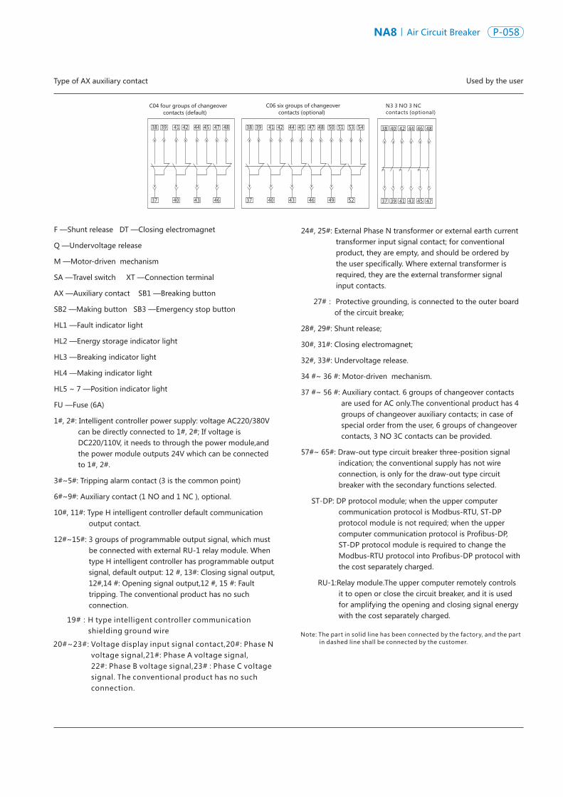
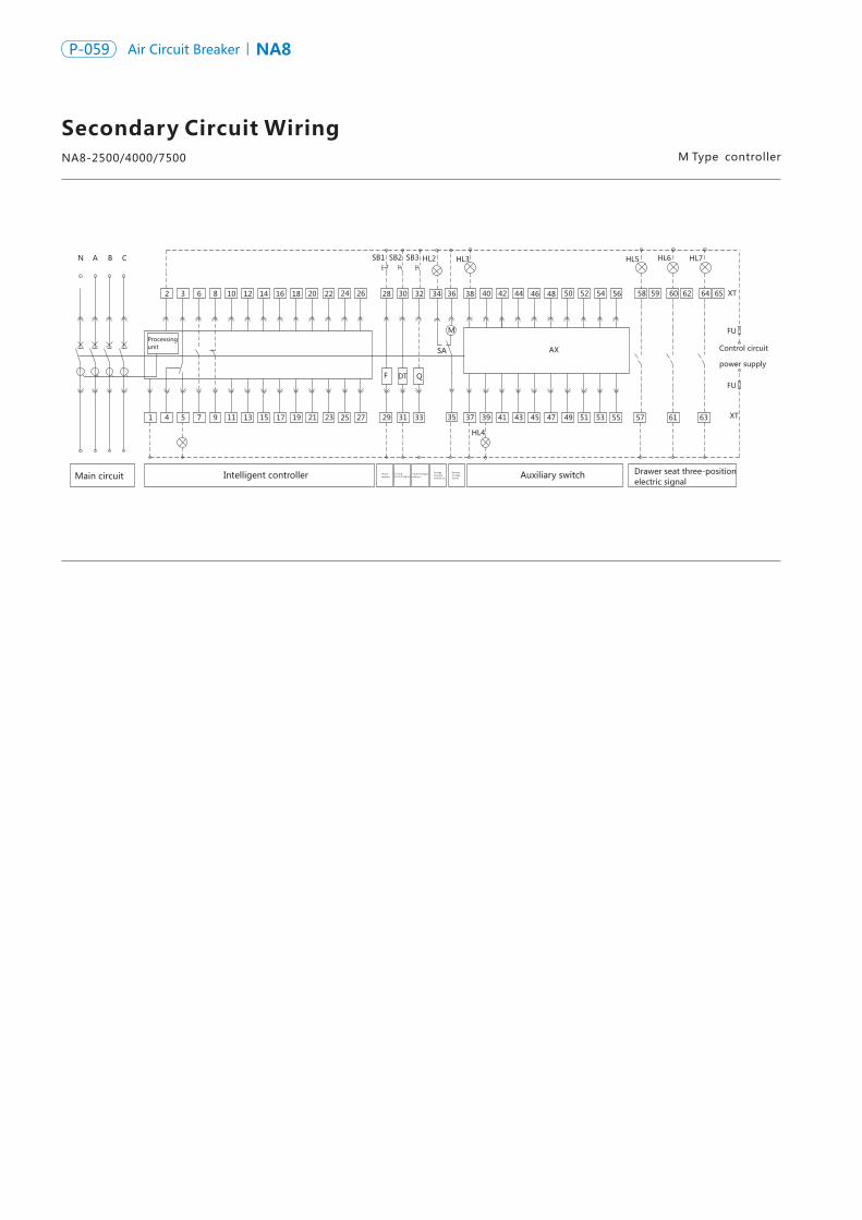
NA8 Air Circuit Breaker P-060P-059 NA8Air Circuit Breaker
Secondary Circuit WiringM Type controllerNA8-2500/4000/7500 Used by the user
C 06 six groups of changeover contacts (optional)
N 4 4NO&4NC contacts (optional) N 5 contacts (optional)5NO&5NC
Type of AX auxiliary contact
37
38 39
40
41 42
43
44 45
46
47 48
37
38 39
40
41 42
43
44 45
46
47 48
49
50 51 53 54
52 37 37
38 38
39 39 43 43 45 45 49 49 5347 47 51 51 55
40 40 42 42 44 44 48 48 52 52 56 46 46 50 50 54
41 41
22 24 26 28 30 32 36 38
SB2
5 7 9 11 19
44 46 4842
Auxiliary switch Drawer seat three-position electric signal
SB1
Main circuit Intelligent controller
A B CN
Processing unit
63
Control circuit
power supply
2 18
FU
XT
1715134
40 50 52 56 58 60 6459 62 6554208 10 14
1
SB3
25 272321 29 31 33
34
35 37 39 41 43 45 47 49 51 53 55 57 61 63
SA
F DT Q
M
AX
HL2 HL3 HL5 HL6 HL7
HL4
XT
FU
12 16
Shunt release
Clos ing electromagnet
Undervoltage release
Energy storage indication
Energystorage motor
C 04 four groups of changeover contacts (default)
F—Shunt release DT —Closing electromagnet
Q —Undervoltage release
M—Motor-driven mechanism
SA—Travel switch XT—Connection terminal
AX—Auxiliary contact SB1—Breaking button
SB2—Making button SB3—Emergency stop button
HL1—Fault indicator light HL2—Energy storage indicator light
HL3—Breaking indicator light HL4—Making indicator light
HL5 ~ 7—Position indicator light
FU—Fuse (6A)
1#, 2#: Intelligent controller power supply: voltage AC220/380V can be directly connected to 1#, 2#; If voltage is DC220/110V, it needs to through the power module,and the power module outputs 24V which can be connected to 1#, 2#.
3#~ 5#: Tripping alarm contact (3 is the common point)
6#~ 9#: Auxiliary contact (1 NO and 1 NC),optional
10#, 11#: Empty
12#~ 19#: Empty
20#: Empty
21#~ 24#: Empty
24#, 25#: The contacts for external Phase N transformer input signal; for conventional product, they are empty, and should be ordered by the user specifically. Where external transformer is required, they are the external transformer signal input contacts.
27#:
28 #, 29 #: Shunt release;
30#, 31#: closing electromagnet;
32 #, 33 #: Undervoltage release.
34 #~36 #: Motor-driven mechanism.
37#~56#: Auxiliary contact. 6 groups of changeover contacts are used for AC only.The conventional product has 4 groups of changeover auxiliary contacts; in case of special order from the user, 6 groups of changeover contacts, 4 NO 4 NC contacts and 5 NO 5 NC contacts can be provided.
57#~ 65#: Draw-out type circuit breaker three-position signal indication, the conventional supply has not wire connection, is only for the draw-out type circuit breaker with the secondary functions selected.
Note: The part in solid line has been connected by the factory, and the part in dashed line shall be connected by the customer.
Protective grounding, is connected to the outer board of the circuit breaker;
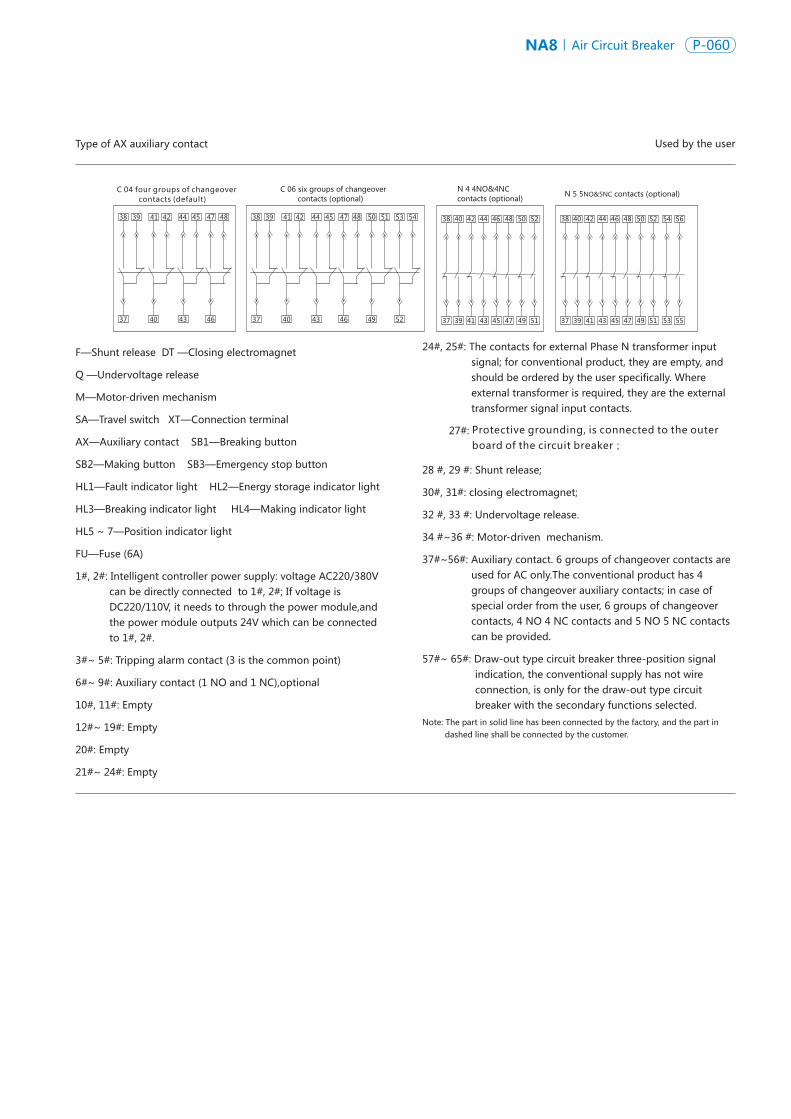
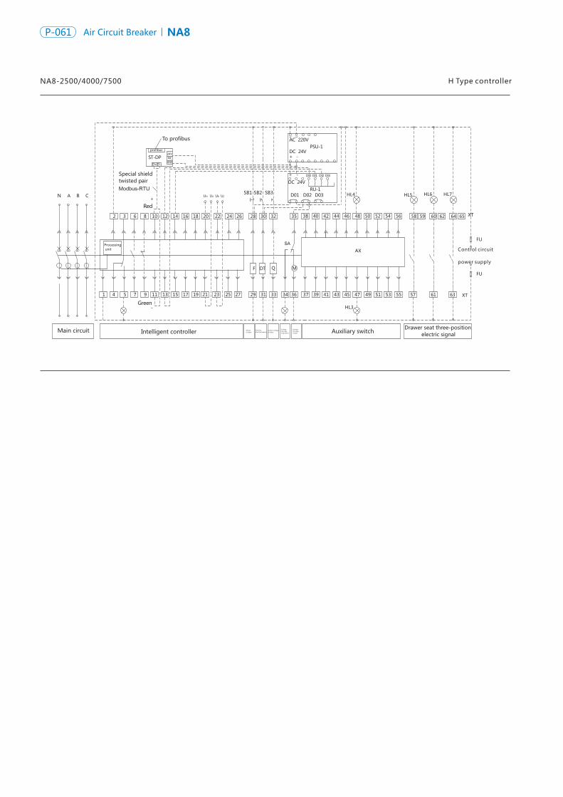
NA8 Air Circuit Breaker P-062P-061 NA8Air Circuit Breaker
H Type controllerNA8-2500/4000/7500
C04 four groups of changeover contacts (default)
C06 six groups of changeover contacts (optional)
N4 4NO&4NC contacts (optional) N5 5NO&5NC contacts (optional)
Used by the userType of AX auxiliary contact
37
38 39
40
41 42
43
44 45
46
47 48
37
38 39
40
41 42
43
44 45
46
47 48
49
50 51 53 54
52 37 37
38 38
39 39 43 43 45 45 49 49 5347 47 51 51 55
40 40 42 42 44 44 48 48 52 52 56 46 46 50 50 54
41 41
58 60 6459 62 65
57 61 63
HL5HL4
HL3
HL6 HL7
To profibus
profibus 24VNCGND
D+D-
ST-DP
N A B C
2 3 6 8 10
Red+
12 14 16 18 20 22 24 26 28 30 32 35 38 40 42 44 46 48 50 52 54 56
Special shieldtwisted pairModbus-RTU
UN A BU CUSB2SB1 SB3
AC 220V
-+DC 24V
PSU-1
-+DC 24V
DI0 DI1 DI2 DI3
RU-1D01 D02 D03
Processing unit
SA
QF DT M
1 4 5 7 9 11
Green-
13 15 17 19 21 23 25 27 29 31 33 34 36 37 39 41 43 45 47 49 51 53 55 XT
FU
XT
FU
AX
U
Auxiliary switchDrawer seat three-position electric signal
Main circuit Intelligent controller Shunt release
Closingelectromagnet
Undervoltage release
Energy storage indication
Energystorage motor
Control circuit
power supply
F —Shunt release DT —Closing electromagnet
Q —Undervoltage release
M —Motor-driven mechanism
SA —Travel switch XT —Connection terminal
AX —Auxiliary contact SB1 —Breaking button
SB2 —Making button SB3 —Emergency stop button
HL1 —Fault indicator light HL2 —Energy storage indicator light
HL3 —Breaking indicator light HL4 —Making indicator light
HL5~7 —Position indicator light
FU —Fuse (6A)
1#, 2#:Intelligent controller power supply: voltage AC220/380V can be directly connected to 1#, 2#;If voltage is DC220/110V, it needs to through the power module,and the power module outputs 24V which can be connected to 1#, 2#.
3#~5#: Tripping alarm contact (3 is the common point)
6#~9#: Auxiliary contact (NO contact), optional.
10# , 11#: Type H intelligent controller default communication output contact.
12#~15#: 3 groups of programmable output signal, which must be connected with external RU-1 relay module.When type H intelligent controller has programmable output signal, default output: 12#, 13#: Closing signal output, 12#, 14#: Opening signal output, 12#, 15 #: Fault tripping. The conventional product has no such connection.
19#: H type intelligent controller communication shielding ground wire
24#, 25#: External Phase N transformer or external earth current transformer input signal contact; for conventional product, they are empty, and should be ordered by the user specifically., where external transformer is required, they are the external transformer signal input contacts.
27#:Protective grounding, is connected to the outer board of the circuit breake;
28 #, 29 #: Shunt release;
30#, 31#: Closing electromagnet;
32#, 33#: Undervoltage release.
34 #~ 36 #: Motor-driven mechanism.
37 #~56 #: Auxiliary contact. 6 groups of changeover contacts are used for AC only. The conventional product has 4 groups of changeover auxiliary contacts; in case of special order from the user, 6 groups of changeover contacts, 4 NO 4 NC contacts or 5 NO 5 NC can be provided.
57#~ 65#: Draw-out type circuit breaker three-position signal indication, the conventional supply has not wire connection, is only for the draw-out type circuit breaker with the secondary functions selected.
ST-DP: DP protocol module, when the upper computer communication protocol is Modbus-RTU, ST-DP protocol module is not required; when the upper computer communication protocol is Profibus-DP, ST-DP protocol module is required to change the Modbus-RTU protocol into Profibus-DP protocol with the cost separately charged.
RU-1: Relay module. The upper computer remotely controls it to open or close the circuit breaker, and it is used for amplifying the opening and closing signal energy with the cost separately charged.
Note: The part in solid line has been connected by the factory, and the part in dashed line shall be connected by the customer.
20#~23#:Voltage display I nput signal contact, 20#: Phase N voltage signal, 21#: Phase A voltage signal, 22#: Phase B voltage signal, 23#: Phase C voltage signal. The conventional product has nsuch connection.
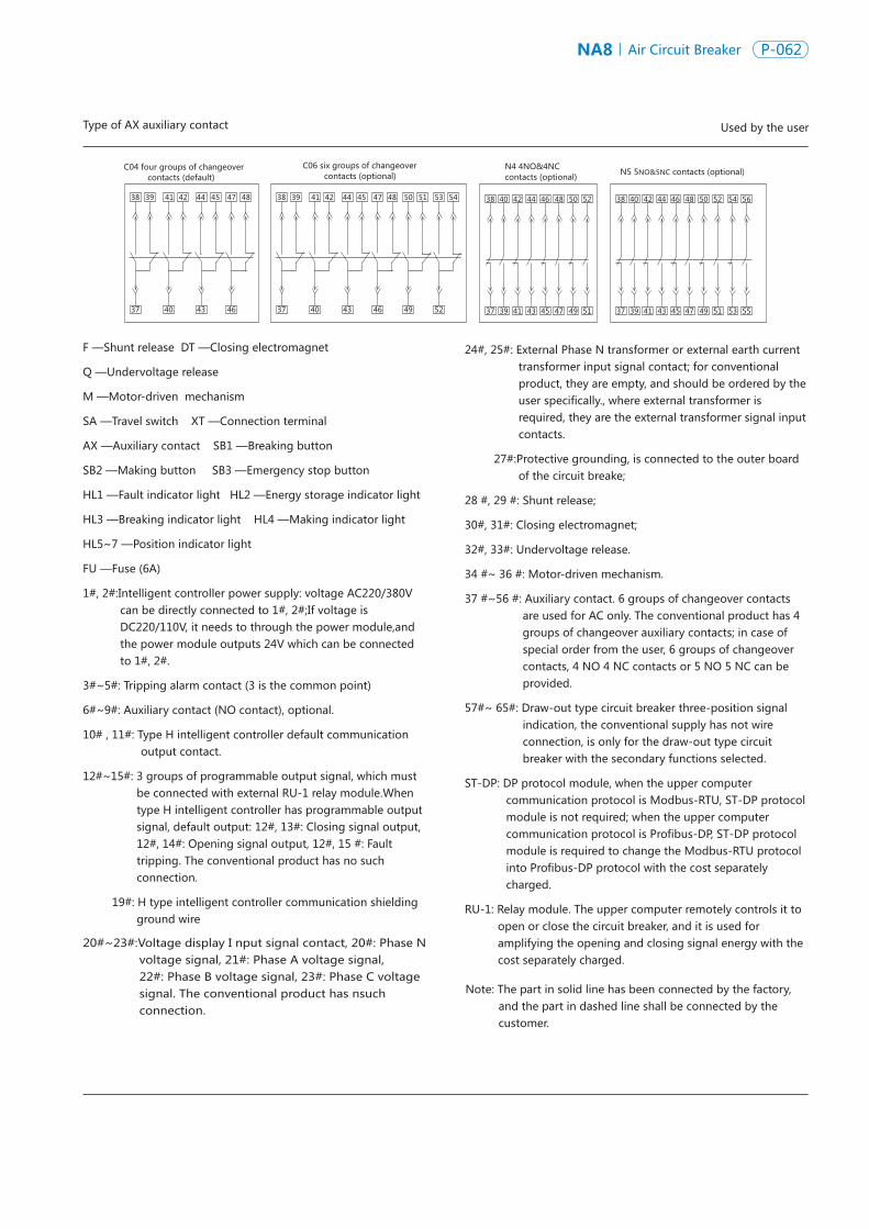
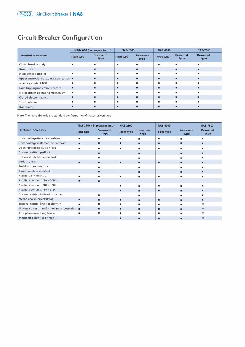
NA8 Air Circuit Breaker P-064P-063 NA8Air Circuit Breaker
Circuit Breaker Configuration
Standard component
NA8-1600(In preparation...) NA8-2500 NA8-4000 NA8-7500
▪
▪▪
▪▪▪▪▪
▪
▪▪
▪▪▪▪▪
▪▪
▪▪
▪▪▪▪▪
▪
▪▪
▪▪▪▪▪
▪▪
▪▪
▪▪▪▪▪
▪ ▪
▪ ▪▪ ▪
▪ ▪▪ ▪▪ ▪▪ ▪▪ ▪
▪ ▪
NA8-2500 NA8-4000 NA8-7500
▪
▪
▪
▪▪
▪
▪▪
▪▪▪
▪
▪
▪
▪▪
▪
▪▪
▪▪▪▪
▪▪
▪▪
▪
▪
▪
▪▪
▪
▪
▪▪
▪▪▪
▪
▪
▪
▪▪
▪
▪
▪▪▪▪▪▪
▪▪
▪▪
▪
▪
▪
▪▪
▪
▪
▪▪
▪▪▪
▪ ▪
▪▪
▪
▪
▪
▪
▪▪ ▪
▪ ▪
▪ ▪
▪ ▪▪ ▪▪ ▪▪ ▪▪ ▪▪ ▪
▪ ▪▪ ▪
▪ ▪▪ ▪
▪
Circuit Breaker Type Selection TableFrame current
Circuit breaker
Mounting mode
Intelligent controller
Shunt, closing, motor
Undervoltage release
NA8-2500 NA8-4000 NA8-7500
N □ H □ H □
200A □
400A □
630A □
800A □
1000A □
1250A □
1600A □
630A □
800A □
1000A □
1250A □
1600A □
2000A □
2500A □
2000A □ 4000A □
2500A □ 5000A □
3200 A □
4000 A □
6300A □
7500A □
3 poles □ 4 poles □
type M(basic type )
□ type H(communication type )
□
Closing electromagnet □ Shunt release □AC220/230V □ AC380/400 V □ DC220V □ DC110V □
UVT □ UVTD □
AC220/230 V □ AC380/400 V □
Interphase insulating barrier □
External transformer : Phase N external transformer □Controller functions : 3P + N protection function □
Ground current protection transformer □ Ground current protection function □
Signal contact output function □
Breaking/Making button lock □ One lock one key □ Two locks one key □ Three locks two keys □
Wire rope interlock (two interlock) □
Draw-out type □
Horizontal connection □
Fixed type □ ( NA8-7500 has no fixed type )
Mixed connection □ ( indicating the connection mode )Vertical connection □
Energy storage motor □
NA8-1600 extension busbar □
Drawer seat three-position signal device □
External LEC leakage transformer □Leakage protection function □
Electric energy measurement and protection function □
Load monitoring function □
Voltage measurement and protection function □
ZSI zone interlock protection function □
Wire rope interlock (MIT-3) □ Wire rope interlock (MIT- 4)
Module (optional) PSU-1 □ RU-1 □ ST-DP protocol conversion module □
Auxiliary contactNA8-1600 C04(standard) C 06 □(only for AC ) N3 □(only for AC)
NA8-2500、NA8-4000~7500 C04(standard) C 06 □ N4 □ N5 □
□
Circuit breaker body
Drawer seat
Intelligent controller
Upper and lower horizontal connection
Auxiliary contact 4CO
Fault tripping indication contact
Motor-driven operating mechanism
Closed electromagnet
Shunt release
Door frame
Optional accessory
Undervoltage time delay release
Undervoltage instantaneous release
Opening/closing button lock
Drawer position padlock
Drawer safety barrier padlock
Body key lock
Position door interlock
Condition door interlock
Auxiliary contact 6CO
Auxiliary contact 3NO + 3NC
Auxiliary contact 4NO + 4NC
Auxiliary contact 5NO + 5NC
Drawer position indication contact
Mechanical interlock (two)
Fixed typeDraw-out type Fixed type Draw-out
typeDraw-out typeFixed type
Draw-out type
Fixed typeDraw-out type Fixed type Draw-out
typeDraw-out typeFixed type Draw-out
type
Rated current
Number of poles
Busbar connection mode
Auxiliary contact indication (optional)
Connecting accessory (optional)
Controller function and accessories (optional)
Mechanical interlock (optional)
Notes: 1) For 3P + N protection function, the phase N external transformer must be selected at the same time; 2) For the leakage protection function, the external LEC leakage transformer must be selected at the same time; 3) For the ground current protection function, the ground current protection transformer must be selected at the same time.
Lock mechanism (optional)
Remark: Upon placing an order, the frame current, rated current and auxiliary control voltage must be indicated!
Notes: 1) Please check the □ corresponding to required option with “√” or “-”, and fill the figure; if there is no marking, we will provide the goods according to the conventional factory setting.
2) If the additional functions and special requirement are selected, additional expense will incur separately. TEL: 0577-62877777 – 706213. FAX: 0577 - 62877777–706288.
NA8-1600(In preparation...)
▪▪▪
NA8-1600(In preparation...)
External neutral line transformer
Ground current transformer and accessories
Interphase insulating barrier
Mechanical interlock (three)
Note: The table above is the standard configuration of motor-driven type
N □
4000A □
5000A □
6300A □
7500A □
H □
1600A □
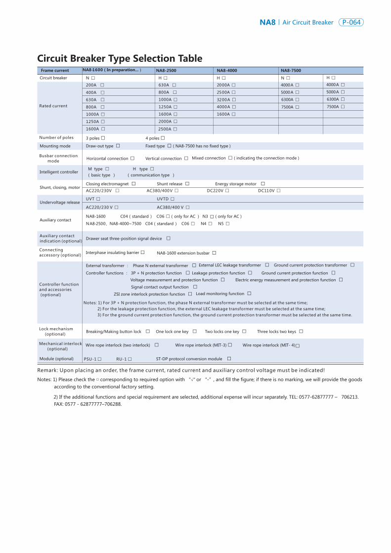

NA8 Air Circuit Breaker P-066P-065 NA8Air Circuit Breaker
Configuration explanations
II. Optional configuration (with additional expense)
NA8-1600 optional configuration explanations: undervoltage instantaneous release, undervoltage time delay release, wire rope interlock,
key lock, external transformer earth protection function, 6 groups of changeover contacts, 3NO 3NC contacts, H type intelligent controller,
optional type H function, interphase insulating barrier, position signal.
NA8-2500、NA8-4000~7500 optional configuration explanations: undervoltage time delay release (1s~5s adjustable), wire rope interlock, button lock, key lock, door interlock,external transformer ground protection function, vertical connection, 6 groups of changeover
contacts, 4NO 4NC contacts, 5NO5NCcontacts, type H intelligent controller, optional H type function, position signal.
I. NA8-1600~2500、NA8-4000 ~7500 conventional configuration explanationsShunt release, closing electromagnet, 4 groups changeover
contacts, motor, M type intelligent controller, main circuit horizontal connection, door frame,main circuit mounting bolts, circuit breaker
operation manual, packing case, drawer seat (draw-out type circuit breaker)
Note