Embed Size (px)
Citation preview
Final Report
Expert’s Report for An Board Pleanála on Environmental Impact Statement for Dart Underground, Dublin
Assessment of the Environmental Impacts in
Relation to Ground Vibrations and Groundborne
Noise, Geotechnical, Hydrogeological and
Construction-related Issues
August 2011
By K. Rainer Massarsch
Ferievägen 25, SE 168 41 BROMMA, Sweden
2
Contents
1 Executive Summary ..................................................................................................... 7
1.1 Background ................................................................................................................ 7
1.2 Available Information ................................................................................................ 7
1.3 DART Underground Scheme .................................................................................... 7
1.4 Community Liaison ................................................................................................... 8
1.5 Review Process .......................................................................................................... 8
1.6 Environmental Impacts .............................................................................................. 8
1.6.1 Environmental Impact Statement ....................................................................... 8
1.6.2 Environmental Risk Management and Enforcement .......................................... 9
1.6.3 Building Damage Classification ......................................................................... 9
1.6.4 Property Protection Scheme ............................................................................. 10
1.6.5 Construction Aspects ........................................................................................ 10
1.6.6 Soils and Geology ............................................................................................. 10
1.6.7 Hydrogeology ................................................................................................... 10
1.6.8 Geotechnical Impact ......................................................................................... 11
1.6.9 Vibration and Groundborne Noise ................................................................... 11
1.7 Conclusions and Recommendations ........................................................................ 12
1.8 Summary of Comments and Recommendation ....................................................... 12
2 Introduction ............................................................................................................... 19
2.1 Background .............................................................................................................. 19
2.2 Brief for the Consultant ........................................................................................... 19
2.3 Acceptance of Appointment .................................................................................... 19
2.4 Definition of Subject Areas ..................................................................................... 20
2.5 Oral Hearing ............................................................................................................ 21
2.6 Availability of Information ...................................................................................... 22
2.6.1 Environmental Impact Statement ..................................................................... 22
2.6.2 Submissions by Observers prior to Oral Hearing ............................................. 22
2.6.3 Evidence and Submissions during Oral Hearing .............................................. 23
2.6.4 Questioning During Oral Hearing .................................................................... 23
2.7 Objective and Scope of Report ................................................................................ 23
2.8 Hierarchy of Documents .......................................................................................... 24
2.9 Description of the Scheme ....................................................................................... 25
2.10 Design Considerations ............................................................................................. 25
2.11 Structure of the Report ............................................................................................. 27
3
3 Environmental Impact Statement (EIS) .................................................................. 29
3.1 General ..................................................................................................................... 29
3.2 Structure and Contents of EIS ................................................................................. 29
3.3 Comments and Recommendation on Structure of EIS ............................................ 30
4 Environmental Risk Management ........................................................................... 31
4.1 Methodology ............................................................................................................ 31
4.2 Environmental Risk Assessment ............................................................................. 31
4.3 Commitment by Applicant on Risk Management ................................................... 32
4.4 Limiting values ........................................................................................................ 33
4.5 Monitoring ............................................................................................................... 35
4.5.1 Applicant’s Evidence on Monitoring ............................................................... 35
4.5.2 Compliance Control .......................................................................................... 37
4.6 Applicant’s Commitments to ERA .......................................................................... 38
4.6.1 Risk Management (M. Conroy, Evidence OH-No. 5): ..................................... 39
4.6.2 Construction Strategy, Scheduling & Programming (K. McManus, Evidence
OH-No.18) ........................................................................................................ 39
4.6.3 Oral Hearing Closing Statement (P. Muldoon, Evidence OH-No. 249) .......... 39
4.7 Comments and Recommendation – Environmental Risk Management .................. 40
5 Building Damage Classification ............................................................................... 42
5.1 General Considerations ............................................................................................ 42
5.2 Description of Building Damage ............................................................................. 42
5.3 Condition Survey ..................................................................................................... 43
5.4 Comments and Recommendation – Building Damage Classification ..................... 44
6 Property Protection Scheme ..................................................................................... 46
6.1 Objective .................................................................................................................. 46
6.2 Clarification regarding Property Protection Scheme ............................................... 46
6.3 Comments and Recommendation – Property Protection Scheme ........................... 47
7 Construction Aspects ................................................................................................. 49
7.1 Construction Strategy .............................................................................................. 49
7.1.1 Programme of Works and Phasing ................................................................... 49
7.1.2 Construction Risks and Maximum Working Area ........................................... 50
7.1.3 Comments on Construction Strategy ................................................................ 51
7.2 Main Construction Methods .................................................................................... 52
7.2.1 Cut and Cover Sub-surface Works ................................................................... 52
7.2.2 Wall Construction ............................................................................................. 52
7.2.3 Soil Excavation ................................................................................................. 53
4
7.2.4 Ground Anchors................................................................................................ 54
7.2.5 Ground Treatment ............................................................................................. 54
7.2.6 Groundwater and Dewatering ........................................................................... 55
7.2.7 Running Tunnel Construction .......................................................................... 56
7.2.8 Rock Excavation ............................................................................................... 57
7.3 Comments and Recommendation – Construction Aspects ...................................... 58
8 Soils and Geology ....................................................................................................... 60
8.1 General ..................................................................................................................... 60
8.2 Description of Project Area ..................................................................................... 60
8.2.1 Geological Conditions ...................................................................................... 60
8.2.2 Engineering Properties of Rock ........................................................................ 61
8.2.3 Seismicity ......................................................................................................... 62
8.2.4 Geotechnical Aspects........................................................................................ 62
8.2.5 Radon ................................................................................................................ 63
8.2.6 Contaminated Ground and Aggressive Soil and Groundwater......................... 63
8.3 Impact Assessment .................................................................................................. 64
8.3.1 General .............................................................................................................. 64
8.3.2 Significance Rating ........................................................................................... 64
8.3.3 Construction Impact and General Mitigation Measures ................................... 65
8.3.4 Operational Impact and General Mitigation Measures ..................................... 66
8.4 Comments and Recommendation – Soils and Geology .......................................... 66
9 Hydrogeological Conditions ..................................................................................... 68
9.1 General ..................................................................................................................... 68
9.2 Hydrogeology of Project Area ................................................................................. 68
9.2.1 Groundwater ..................................................................................................... 68
9.2.2 Engineering Geology ........................................................................................ 69
9.2.3 Hydrochemistry ................................................................................................ 69
9.2.4 Site Investigation and Monitoring .................................................................... 70
9.3 Impact Assessment Methodology ............................................................................ 71
9.4 Impact Assessment .................................................................................................. 72
9.4.1 General Impact.................................................................................................. 72
9.4.2 Running Tunnels ............................................................................................... 72
9.4.3 Stations and Shafts ............................................................................................ 72
9.4.4 Enabling Works ................................................................................................ 72
9.5 Mitigation Measures ................................................................................................ 73
9.5.1 General Mitigation Measures ........................................................................... 73
5
9.5.2 Construction of Tunnels and Cross Passages ................................................... 73
9.5.3 Construction of Retaining Walls ...................................................................... 73
9.5.4 Temporary Dewatering ..................................................................................... 73
9.5.5 Groundwater Abstractions ................................................................................ 74
9.5.6 Hydrochemistry ................................................................................................ 74
9.6 Site-specific Construction Impact and Mitigation ................................................... 74
9.6.1 Inchicore Cut and Cover, Inchicore Station and Inchicore Intervention Shaft. 75
9.6.2 Inchicore to Heuston Station ............................................................................ 75
9.6.3 Heuston Station to Christchurch Station........................................................... 75
9.6.4 Christchurch Station to St. Stephen’s Green Station ........................................ 76
9.6.5 St. Stephen’s Green Station to Pearse Station .................................................. 76
9.6.6 Pearse Station to Docklands Station ................................................................. 77
9.6.7 Eastern Portal and Cut and Cover Section ........................................................ 77
9.7 Operational Impact .................................................................................................. 77
9.8 Comments and Recommendation - Hydrogeology .................................................. 78
10 Geotechnical Conditions ........................................................................................... 79
10.1 General ..................................................................................................................... 79
10.1.1 Field Tests ......................................................................................................... 80
10.1.2 Laboratory tests: ............................................................................................... 80
10.2 Geophysical Testing ................................................................................................ 80
10.3 Ground Conditions ................................................................................................... 80
10.4 Extent of Ground Investigations .............................................................................. 84
10.5 Reliability of Geotechnical Properties ..................................................................... 84
10.6 Dynamic Soil Parameters ........................................................................................ 87
10.7 Geotechnical Hazards .............................................................................................. 89
10.7.1 General .............................................................................................................. 89
10.7.2 Geotechnical and Geological Hazards .............................................................. 90
10.7.3 Construction-related Hazards ........................................................................... 91
10.7.4 Stability of Structures ....................................................................................... 92
10.7.5 Settlement and Ground Movement ................................................................... 92
10.8 Site-specific Construction Impact and Mitigation ................................................... 96
10.8.1 Inchicore Cut and Cover, Inchicore Station and Inchicore Intervention Shaft. 96
10.8.2 Inchicore to Heuston Station ............................................................................ 97
10.8.3 Heuston Station to Christchurch Station........................................................... 99
10.8.4 Christchurch Station to St. Stephen’s Green Station ...................................... 101
10.8.5 St. Stephen’s Green Station to Pearse Station ................................................ 102
10.8.6 Pearse Station to Docklands Station ............................................................... 104
6
10.8.7 Eastern Portal and Cut and Cover Section ...................................................... 107
10.9 Comments and Recommendations – Geotechnical Impact ................................... 109
11 Vibration and Groundborne Noise ........................................................................ 111
11.1 General ................................................................................................................... 111
11.2 Dynamic Soil Properties of Soil and Rock ............................................................ 111
11.3 Vibration Hazards .................................................................................................. 112
11.3.1 Enabling Works .............................................................................................. 112
11.3.2 Construction Phase ......................................................................................... 112
11.3.3 Operational Phase ........................................................................................... 112
11.4 Assessment of Ground Vibration ........................................................................... 113
11.4.1 Construction Phase ......................................................................................... 113
11.4.2 Operational Phase ........................................................................................... 115
11.5 Impact Criteria ....................................................................................................... 116
11.5.1 General ............................................................................................................ 116
11.5.2 Human Response ............................................................................................ 117
11.5.3 Utilities ........................................................................................................... 125
11.5.4 Vibration-sensitive Equipment and Processes ................................................ 125
11.5.5 Building Damage ............................................................................................ 126
11.6 Proposed Mitigation Measures in EIS ................................................................... 126
11.7 Comments and Recommendation – Vibration and Groundborne Noise ............... 128
7
1 Executive Summary This report presents the results of my evaluation of the Environmental Impact Statement
submitted to An Bord Pleanála and information gathered during the Oral Hearing for the
proposed construction of the DART Underground Scheme.
1.1 Background
Córas Iompair Éireanne (CIÉ), called the Applicant, has applied to An Bord Pleanála
(ABP) for a Railway Order of a high capacity DART Underground line running
underground through Dublin City centre.
ABP has appointed an in-house Inspector to examine and report on this Railway Order
application. According to instructions by ABP, I have assisted the Inspector in a specialist
capacity, covering the subject areas: geotechnical engineering (e.g. issues related to
settlement, tunnelling and excavation etc.), hydrogeology (groundwater flow, groundwater
lowering, groundwater contamination etc.) and ground vibration (including groundborne
noise).
1.2 Available Information
The Environmental Impact Statement (EIS) was submitted to ABP as part of the
application for a Railway Order to construct the DART Underground. In addition to
reviewing the EIS and attending the Oral Hearing I have also assessed evidence and other
information submitted by the Applicant, by Prescribed Bodies and Observers in relation to
the above matters, prior to and during the Oral Hearing.
The Oral Hearing has been thorough and matches the ambitions of the Applicant to realize
a world-class railway project that will cause minimal residual impacts on the environment.
The evidence provided by the Applicant was generally of high standard and presented
clearly and exhaustively. Response to questions was comprehensive.
Observers were given the opportunity to present their observations and to express their
concerns related to the construction and operation of the DART Underground. The
commitment and thoroughness of observations (submission and evidence provided by their
experts) presented by residents living along the DART Underground is acknowledged.
This information provided a valuable background when preparing this report.
This report is based on the body of information as it was available at the end of the Oral
Hearing in April 2011.
1.3 DART Underground Scheme
DART Underground is an important project to further enhance the transport infrastructure
of Dublin City which will generate an integrated public transportation network. The
Scheme is similar in concept and design to several projects carried out successfully in
major European cities. DART Underground will be the first major tunnelling project to be
constructed in the centre of Dublin.
Although there is general support for the DART Underground Scheme, objections have
been made to certain aspects of the project. It is not possible to eliminate completely
during construction nuisance and negative impact on the city, to its population and
businesses. Due to the envisaged long duration and complexity of the project it is
8
important that genuine concerns by Observers are taken seriously. However, if properly
planned, constructed, operated and maintained, the residual environmental impacts will be
kept to a minimum.
Impacts can be minimised by implementation of efficient mitigation measures and rigorous
supervision and independent monitoring. By applying modern environmental risk
management concepts it can be assured that construction and operation of the scheme is
carried out according to the requirements and conditions set out in the Railway Order.
1.4 Community Liaison
Community liaison and interaction between the Applicant, the Contractor and the public
shall be an essential element of the mitigation process throughout the project.
Transparency with regard to the impact of planned construction activities, extensive
monitoring and communication with the public are of importance. The Applicant is
committed to establishing efficient community liaison procedures.
The Applicant has confirmed that all complaints or issues received and relating to
compliance with the Railway Order or construction/operational nuisances will be relayed
to the Contractor, an Independent Environmental and Archaeological Monitor and the CIÉ
management team. All such complaints or issues raised will be actively processed until
closure.
1.5 Review Process
The Oral Hearing is an important part of the Environmental Impact Assessment process. It
lasted for 62 days and was very thorough. During Module 1 of the Oral Hearing the
Applicant summarised the contents of the EIS and provided clarification to questions
raised by the Board (Note 1 of the Order of Proceedings). During the following Modules
the submissions and evidence by Observers and their experts were presented. The
Applicant was questioned extensively and responded to all queries by ABP Experts and
questions raised by Observers.
In submissions received prior to and during the Oral Hearing, Observers presented well-
documented information and statements of their concerns. The clarifications obtained
during extensive questioning of the Applicant are an important source of information in
preparation of this report.
1.6 Environmental Impacts
This report contains my recommendations regarding the application by the Applicant for
the Railway Order. The report is divided into chapters according to the scope of my brief.
Comments and recommendations are given at the end of each chapter. Important
background information is contained in five Appendices. Of particular importance is
Appendix 4 which documents in detail the submissions made by Observers, response by the
Applicant and review comments.
The following comments are a summary of statements provided in more detail in the main
report.
1.6.1 Environmental Impact Statement
The EIS submitted to ABP was comprehensive and addresses the main concerns of
environmental impact. The EIS is considered adequate for application for a Railway Order.
9
However, in some aspects it is very brief and background information difficult to access.
The structure and presentation of information in the EIS is satisfactory. However, some
deficiencies have been noted. For instance, limiting criteria of environmental impact must
be stated unambiguously as these otherwise would be difficult to enforce.
Evidence provided by the Applicant during the Oral Hearing added important clarifications
and valuable factual information.
1.6.2 Environmental Risk Management and Enforcement
The Applicant confirmed the commitment to the implementation of a comprehensive risk
management framework which shall ensure that all works for DART Underground will be
in compliance with the requirements of a Railway Order. At all times during construction
and operation, the Applicant will retain all obligations imposed by the Railway Order.
Verifiable limiting values with respect to environmental impact shall be closely monitored
and reviewed by an Independent Environmental and Archaeological Monitor (E&AM) to
verify that the Contractor and the Applicant comply with requirements set out in the
Railway Order. In addition to information given in the EIS the Applicant described in
evidence given during the Oral Hearing a rigorous risk management framework which will
extend from project inception through the life of the project. This firm commitment further
enhances the quality of environmental impact control and minimise negative consequences
to the environment.
Environmental Risk Management, for both constructional and operational stages, shall be
as indicated by the applicant in the ‘Brief of Evidence – Risk Management Concept’
submitted to the Oral Hearing into the Railway Order application on the 1st day of
December 2010, ‘Brief of Evidence – Monitoring’ submitted to the Oral Hearing on the
14th
day of January 2011 and ‘Oral Hearing Closing Statement’ submitted to the Oral
Hearing on the 8th
day of April 2011.
1.6.3 Building Damage Classification
The building damage classification system proposed in the EIS is widely accepted and
suitable for the project.
A panel of independent chartered building surveying companies shall be established and
instructed by the Applicant regarding requirements and responsibilities when evaluating
building damage.
Building damage exceeding Category 2 shall be avoided wherever possible. Trigger levels
of the monitoring scheme shall be set not to exceed damage Category 2 and Category 1 for
historic buildings identified on the Record of Protected Structures, respectively. The
contractor shall be informed immediately and be required to modify or adjust the
construction process to avoid further damage. Changes of working method shall be
approved by the Applicant and/or the E&AM.
When building damage corresponding to or exceeding Category 2 is noted an interim
survey shall be carried out without delay. Repair work shall be implemented without undue
delay.
Assurances were given by the Applicant that particular attention will be paid to the
protection and monitoring of historic buildings with ornate plaster ceilings.
10
1.6.4 Property Protection Scheme
As an added assurance to owners of properties along the DART Underground the
Applicant has introduced a Property Protection Scheme (PPS). It is aimed at simplifying
the rectification and repair of minor damage which can arise due to construction work. The
Property Protection Scheme and in particular the limit to repair cost of € 30,000 has caused
extensive discussions and objection from some property owners. However, the PPS must
be seen in the context of unlimited liability of the Applicant and the Contractor for any
damage caused due to the construction work.
It is important that the Applicant retains full responsibility for setting up and implementing
the Property Protection Scheme throughout the construction of the DART Underground
Scheme.
1.6.5 Construction Aspects
The proposed methods off tunnel construction and deep excavation have been used
successfully in similar geological settings and geotechnical conditions elsewhere. I endorse
the proposed construction of two running tunnels by tunnel boring machines (TBMs) with
a launch portal at East Wall and a reception chamber at Inchicore. Tunnel shall be
constructed about 25m below the city centre, which is not expected to cause significant
settlement and vibration impact, provided that the proposed mitigation measures are
implemented.
Construction of stations and shafts by the top down method is the preferred alternative in
the city centre as this reduces negative environmental impact to short periods during
excavation.
Difficulties can be encountered when the tunnels are constructed in mixed face conditions.
Evidence obtained during the Oral Hearing suggests that soil properties and rockhead level
can vary more than anticipated. This aspect needs to be taken into account when selecting
construction and tunnelling methods. The proposed earth pressure balance (EPB) machine
is in my view suitable to carry out tunnelling work under such ground conditions.
1.6.6 Soils and Geology
The description of the general geological situation along the DART Underground route is
comprehensive and sufficient for assessing environmental impacts of the Scheme.
However, impact of geotechnical and geological conditions on construction work is only
addressed briefly in the EIS.
The geological and geotechnical conditions are in general favourable for the construction
of running tunnels as well as stations and shafts. However, in some locations the properties
of soil and rock can vary more than anticipated.
A significantly more detailed assessment of the geotechnical and geological conditions
within the tunnel sections and at locations of deep excavations (shafts and stations) will be
required prior to the Detailed Design and start of major construction work.
1.6.7 Hydrogeology
The hydrogeological situation along the running tunnels does not give rise to concerns.
However, supplementary geological and hydrogeological investigations are required in
some areas, also considering ground water and soil contamination.
Dewatering shall be planned and monitored carefully to avoid soil erosion and/or
consolidation settlements.
11
Where deep excavations are to be carried out, a high degree of quality control of
construction work is needed to assure that design specifications with regard to the water-
tightness of walls are actually achieved.
Flooding can have significant impact on the hydrogeological situation in the project area.
This aspect has in my view not been addressed in sufficient detail.
1.6.8 Geotechnical Impact
Geotechnical impact from construction activities was not covered in great detail in the EIS.
Prediction of settlement and assessment of risk areas follows well-accepted concepts and
additional evidence was provided by the Applicant during the Oral Hearing.
However, the EIS lacks an interpretative geotechnical report, describing geotechnical and
rock properties. Some of this information is contained in appendices to the EIS.
Geotechnical investigations cover the project alignment and are adequate for a basic
assessment of ground conditions. However, in areas with difficult ground conditions, more
detailed investigations and suitable investigation method shall be used. Also, additional
detailed geotechnical investigations are needed where deep excavations have to be
constructed in the vicinity of sensitive structures.
Geotechnical design, testing and investigation shall follow requirements stated in European
Standard, Eurocode EN 1997. All foundation work and construction work below ground
shall be carried out in compliance with European standards CEN “Execution of Special
Geotechnical Works”.
1.6.9 Vibration and Groundborne Noise
The assessment of environmental impact from vibration and groundborne noise in the EIS
is comprehensive. However, the accuracy of vibration predictions can be indicative only
and must be verified by field monitoring and full-scale tests during the construction phase
and operation.
In advance of critical activities the contractor shall work out specific method statement and
prepare a vibration mitigation program including field trials.
Prediction models of vibration and groundborne noise are preliminary and must be updated
and calibrated against field measurements.
Limiting values stated for vibration and groundborne noise shall be based - without
modification - on relevant British Standards, where applicable. The application of “change
base criteria” in areas already affected by vibration as proposed in the EIS is not
recommended.
Impact Criteria - Construction Phase
VDV levels proposed in the EIS are acceptable in principle as upper limits for the
construction phase. During night-time work or supply train operation an effort shall be
made not to exceed vibration levels having low probability of adverse comment according
to British Standard: 0.2 m.s
-1.75. Higher VDV values shall be accepted only for short
duration.
Effort shall be made by field trials and modification of the TBM construction process to
limit groundborne noise to levels not exceeding 45 dB LAmax,S during night time. When
measured vibration levels exceed 49 dB LAmax,S during night time, occupants of buildings
shall be offered without delay alternative accommodation or other form of compensation.
12
Impact Criteria - Operational Phase
Groundborne noise night-time in residential areas shall not exceed 35 dBA. Vibration
levels shall not exceed the category of low probability of adverse comments: 0.2 to 0.4 m.s-
1.75 (day-time) and 0.1 to 0.2 m.s
-1.75 (night-time), respectively.
Limits of vibrations and of groundborne noise proposed in the EIS for theatres are
acceptable. The EIS criterion of 25 dB LAmax,S shall be imposed as an absolute and upper
limit according to the frequency distribution given by the Applicant.
Limiting values shall be monitored and enforced rigorously.
1.7 Conclusions and Recommendations
The body of information provided in the EIS, clarifications and evidence presented during
the Oral Hearing have been extensive and meet high standards of environmental risk
assessment.
Concerns expressed by Observers have been taken into consideration in preparation of this
report. The proposed impact criteria are rigorous and based on relevant standards and
international best practice applied at similar projects elsewhere.
The geological and geotechnical conditions are in general favourable for construction of
two running tunnels, stations and shafts along the proposed alignment.
Well-established construction methods are proposed to be employed. TBMs equipped with
earth pressure balance shields is suitable to work under varying hydrogeological,
geological and geotechnical conditions.
The Property Protection Scheme shall be set up and operated by the Applicant throughout
the lifetime of the project. It is an added benefit to owners of property along the alignment.
All buildings affected by the proposed scheme, independent of participation in the Property
Protection Scheme, shall be surveyed and monitored.
A rigorous environmental risk management framework shall be implemented throughout
the project. This includes extensive instrumentation and monitoring of buildings in risk
area. Especially sensitive receptors such as historic buildings shall be protected by special
mitigation efforts and extensive monitoring.
In conclusion I can recommend to the Board that a Railway Order is given, considering the
comments and recommendations in this report.
1.8 Summary of Comments and Recommendation
This section lists the most important comments and recommendations given in the
respective chapters of this report.
Structure of EIS
1. The structure of the EIS is logical and addresses environmental issues which can arise in connection with a major infrastructure project. However, information regarding environmental risk management, and how risk management concepts were implemented during its preparation, are missing.
2. Limiting values or thresholds shall be strictly adhered to and not “in so far as is reasonably practicable” as stated in the EIS.
13
3. Factual information included in the EIS (e.g. results of site investigations) was reported without interpretation and analysis.
4. Although it is recognised that some aspects of environmental risk assessment can be commercially or contractually sensitive, this does in my view not justify that the description of fundamental aspects of environmental risk assessment was omitted.
5. Evidence provided by the Applicant during the Oral Hearing confirmed that strict environmental risk management procedures will be applied.
Environmental Risk Management
1. In response to the request for clarification in Note 1 of the Order of Proceedings and questions during the Oral Hearing, the Applicant has presented comprehensive evidence on risk management.
2. Rigorous risk management shall be applied during construction and operation of the DART Underground. Construction work which can cause environmental impacts shall be monitored carefully.
3. The Observational method as outlined in EN 1997 (Eurocode 7: Geotechnical design) shall be applied in the Detailed Design and mitigation measures implemented without delay should unforeseen conditions be encountered.
4. Evidence on field instrumentation and monitoring was extensive and of high standard. The Applicant has stated the commitment that extensive field monitoring will be implemented to assure compliance with environmental impact criteria.
5. Monitoring of buildings and other structures or installations shall be carried out on a regular basis, results shall be viewed by experts with competence to evaluate and interpret the type of measurement. These interpreted results shall be made available to the public on a weekly basis.
6. Annual compliance monitoring shall be carried out during the operational phase to assure that the DART Underground Scheme is properly maintained.
Building Damage Classification
1. The proposed building damage classification system is widely accepted and suitable for the project. Building damage exceeding Damage Category 2 shall be avoided. Trigger levels of the monitoring scheme shall be set not to exceed damage Category 2, and Category 1 for historic buildings identified on the Record of Protected Structures, respectively.
2. A panel of independent chartered building surveying companies shall be established. Panel members shall be instructed by the Applicant about the requirements of building surveying.
3. Condition surveys shall be carried out for buildings within the risk zone of settlement and vibration (subject to consent of the property owner), these surveys shall be carried out prior to, during and after completion of the Dart Underground.
4. Trigger levels of the monitoring scheme for building damage shall be set not to exceed Category 1 for buildings/structures on the Record of Protected Structures and Category 2 for all other buildings. Should building damage corresponding to Category 1 for buildings/structures on the Record of Protected Structures or Category 2 for all other buildings occur an interim survey shall be carried out without delay. The contractor shall be required to modify or adjust the construction process to avoid any further damage.
14
Changes to the working method shall be agreed with applicant and/or the Independent Environmental & Archaeological Monitor.
5. The contractor shall be required to engage the services of suitably qualified persons in the field of architectural heritage protection in relation to the carrying out of surveys, installation of monitoring instrumentation, interpreting monitoring data and determining appropriate repairs of any damage caused for buildings/structures on the Record of Protected Structures. The Independent Environmental & Archaeological Monitor shall also include persons suitably qualified in architectural heritage protection.
Property Protection Scheme
1. The structure and content of the Property Protection Scheme shall be as indicated in ‘Property Protection Scheme – DART Underground Oral Hearing’ submitted by the applicant to the Oral Hearing on the 19th day of January 2011. The applicant shall retain overall responsibility for the implementation and operation of the Property Protection Scheme throughout the lifetime of the DART Underground (construction and operation).
2. The limit of € 30,000 stated in the EIS shall correspond to construction cost excluding VAT and, and shall be adjusted annually and shall be adjusted annually to reflect cost of working in the construction industry.
Construction Aspects
1. The construction strategy proposed by the Applicant is based on one tunnel portal at East Wall (Eastern Portal), constructing the running tunnels by two TBMs with EPB shields. From a geotechnical and hydrogeological viewpoint, this strategy has advantages with respect to environmental impact, compared to four TBMs (requiring two portals and two reception pits in the city centre). These are:
Only one launch pit for the two TBMs will be required. The proposed site is located within the CIÉ North Wall Depot and suitable for construction of the launch pit from a geotechnical and site-specific viewpoint, compared to alternative sites.
Tunnel boring using only two TBMs may take longer than using four TBMs but the overall construction process will be simplified.
An added benefit for the contractor of using two TBMs is the extended learning process and experience which will result in adaptation of a safe and efficient construction process.
Spoil from TBM excavation can be transported by conveyor belts in the tunnels below the city to the Eastern Portal where it can be transported by rail or truck.
2. Tunnel boring can be complicated when unexpected ground conditions and mixed face boring are encountered. Mixed face tunnelling requires extra care in measuring operational parameters. Prior to the appointment of the selected contractor for the Tunnel Boring Machine (TBM) works, the contractor shall have demonstrated to the applicant sufficient experience in TBM work in ground conditions similar to those expected to be encountered in the construction of the DART Underground tunnels (i.e. mixed face, boulder clay). The required experience shall be verified by the applicant prior to the contractor’s appointment.
3. The proposed construction methods are well-established and extensive practical experience exists in Dublin from similar projects (wall construction, excavation etc.). Construction of running tunnels will be carried out at relatively large depth (20 to 25m) mainly in limestone and stiff, glacial till. This material is suitable for the proposed tunnelling process. For wall construction of Docklands station the secant pile wall method
15
was selected in the EIS. An inspection of existing basement walls in the Docklands area indicates potential problems with water-tightness. The diaphragm wall method has advantages with respect to water-tightness.
4. A final determination on the construction method to be employed in the construction of the Docklands Station (i.e. secant pile walls or diaphragm walls) shall be made based on further ground investigations and monitoring required for the Detailed Design stage, the construction method chosen shall provide for the optimal level of water-tightness.
5. A review of the EIS and evidence obtained during the Oral Hearing suggests that soil properties and rockhead level can vary more than anticipated. This aspect needs to be taken into account when selecting construction and tunnelling methods. The problem of potentially loose, water-saturated soils was identified. Variable ground conditions are not limited to layers of loose sand and gravel but are also important for problems associated with tunnelling across the rock-soil interface. In some locations this is gives rise to a potentially problematic situation for TBM operation. Tunnelling protective measures are often cost-effective in order to reduce excessive ground loss. Therefore, it is recommended that extensive field monitoring procedures are applied during the initial phase of tunnelling work in critical areas to gain experience.
6. The scheme shown on the Alignment and Structures Details drawings is enveloped by a wider maximum working area, and it is this wider area that is indicated on the Property Details drawings. However, as Detailed Design has not yet been carried out, there is some uncertainty as to the actually required land-take (vertical and horizontal), for instance with regard to extended ground treatment and underpinning work.
7. All sub-surface construction works shall be planned, carried out and monitored in compliance with Eurocodes Execution Standards: ‘Execution of Special Geotechnical Works’
Soils and Geology
1. The EIS provides a description of the general geological situation along the alignment. The information is sufficient for assessing environmental impacts of construction activities on soil and rock formations. However, impact of geotechnical and geological conditions on construction of the DART Underground is only addressed in the chapter on Settlement.
2. Information provided as evidence during the Oral Hearing indicates that soil and rock conditions can vary more rapidly over short distances than anticipated.
3. Presently available information on soil and rock is insufficient for Detailed Design and a significantly more detailed assessment of the geotechnical and geological conditions within the tunnel sections and at locations of deep excavations (shafts and stations) is needed.
4. Occurrence of faults, zones of weakness and weathering in rock needs to be determined more reliably, in particular in locations of deep excavations and mixed face tunnelling conditions. An important task is to establish the rockhead level and rockhead conditions along and perpendicular to the DART Underground alignment.
5. The extent of contaminated ground shall be determined by detailed investigations of all areas where excavations are proposed, these investigations shall be conducted prior to the commencement of excavation works as indicated by the applicant in ‘Brief of Evidence – Waste Management’ submitted to the Oral Hearing into the Railway Order application on the 17th day of December, 2010.
16
6. Potential obstructions and hazards including, inter alia, foundations, services, river walls and ordnances relating to the North Strand WWII bombing event shall be identified and addressed in the Detailed Design stage.
Hydrogeology
The Detailed Design stage, to be carried out in compliance with EN 1997 (Eurocode 7: Geotechnical design), shall include, inter alia, the following:
1. A determination of permissible limits (threshold and limiting values) for permanent or temporary groundwater level drawdown
2. Identification of areas and depths of potential contamination of groundwater and soil deposits.
3. A high degree of quality control during deep excavations relating to water-tightness of walls/structures
4. Mitigation proposals to protect groundwater quality and the hydrogeological regime in the event of a flooding occurrence during the construction phase.
Geotechnical Impact
The Detailed Design stage, to be carried out in compliance with EN 1997 (Eurocode 7: Geotechnical design) shall include, inter alia, the following:
1. (i) The inclusion of the following geotechnical and geological hazards in the geotechnical risk assessment and management scheme:
variable and unexpected ground conditions (made ground and fill)
presence of soft, instable and compressive glacio-marine deposits
sand veins (interbedded as sandy laminations in boulder clay) causing dewatering problems
gravel bed resulting in problematic groundwater inflows into excavation
contamination of ground and groundwater
high levels of methane
artesian or sub-artesian water pressure within glacial gravels
instability of shallow excavations in loose and soft ground (especially silty soils)
settlement of structures and installations in the ground (e.g. utilities) due to tunnel construction
settlement of structures and installations in the ground due to permanent lowering of groundwater
ground movements (vertical and horizontal) of structures due to construction of deep excavations
instability of excavations in soil due to fissuring and/or shearing of glacial clays
instability of excavations in rock due to discontinuities, fissuring rock and weathered rock
variability of rockhead level or unexpected deviations from design assumptions
bedded limestone with interbedded shale resulting in stability problems
dip of limestone bedding
voids in rock formation (potential of karstic features)
high groundwater pressure at tunnel level
running sands in boulder clay
difficulties during tunnel boring in mixed face conditions
settlement of loose, granular soil layers induced by blasting vibrations
obstructions to excavations (made ground, boulders etc.)
17
inflow of water into excavations due to granular horizons
unexpected ground conditions
unexploded ordnance within soft or loose superficial deposits
consequences of archaeological excavations
contamination of groundwater.
2. Consideration of the following construction-related hazards:
Construction of water-tight wall elements due to construction deviations and/or obstructions
Seating of wall elements on blocks or fractured rock layers
Instability of excavations in rock due to unfavourable bedding planes
Leakage of groundwater in soil and fractured rock into deep excavations
TBM work in weathered rock and rock formations with potential faults
TBM work in mixed face conditions (soil-rock interface)
TBM work in deposits with layers and lenses of water-bearing sands
Wear on equipment (tunnelling and excavation) due to presence of abrasive ground
Obstructions in made ground encountered during wall construction (affecting verticality of piles/panels and influencing water tightness)
Chiselling required to penetrate boulders and other obstructions
Draw-down of groundwater adjacent to excavation, due excessive pumping in excavations (leakage through or below secant pile or diaphragm wall)
Difficulties with installation and/or retraction of ground anchors in hard rock
Implementation of ground treatment adjacent to tunnels and/or excavations.
3. Geotechnical investigations to include:
Rotary open hole and core investigations
Cone penetration testing (CPT) and in very soft soils with pore water pressure measurements (CPTU)
Laboratory testing to determine strength and stiffness of soil layers
Piezometer installation
Down-hole Geophysical testing including MASW and/or seismic refraction method logging
Contamination screening.
Vibration and Groundborne Noise
I. General Recommendations
1. Limiting values stated for vibration and groundborne noise shall be based - without modification - on relevant British Standards, where applicable. The application of “change base criteria” shall not apply.
2. As part of the Noise and Vibration Monitoring (NMV) program, the contractor shall be required to work out specific method statements for construction work which can give rise to significant ground vibrations. Field trials and tests shall be carried out by the contractor in advance of critical activities. Vibration levels shall be predicted and compared with measured values.
3. Vibration measurements shall be carried out on the ground and inside of vibration-sensitive buildings. A detailed field measurement program shall be worked out by experienced specialists. All tests shall be carried out in cooperation with, or under supervisions by, the engineering team of the Applicant and independent experts.
18
II. Impact Criteria - Construction Phase
1. Vibration impact on humans is based on BS 6472-1:2008 Table 1. VDV levels proposed in the EIS are acceptable in principle as upper limits for the construction phase. During night-time, VDV levels shall not exceed: < 0.2 m.s-1.75 having low probability of adverse comment. (This can be accomplished in many cases by field trials and modification of working methods with potential of causing disturbance.) Higher VDV values shall be accepted only for a short duration (less than 10 minutes) when unexpectedly difficult ground conditions are encountered.
2. When measured vibration levels from TBM works exceed 49 dB LAmax,S during night time, occupants of buildings shall be offered without delay alternative accommodation (or, if agreeable to the contractor and affected party, other form of mitigation). The threshold level of vibration monitoring during TBM operation night-time shall be 45 dB LAmax,S S. When groundborne noise is predicted to exceed 45 dB dB LAmax,S S during night time the contractor shall in cooperation with the Applicant work out an action plan to minimize ground vibrations. An attempt shall be made to modify the construction processes and phasing of work with the aim of reducing groundborne noise to values below 45 dB LAmax,S S.
III. Impact Criteria - Operational Phase
1. Groundborne noise during night-time in residential areas shall not exceed 35 dBA.
2. Vibration levels shall not exceed VDV belonging to the category of low probability of adverse comments: 0.2 to 0.4 m.s-1.75 (day-time) and 0.1 to 0.2 m.s -1.75 (night-time).
3. For Theatres and Marconi House: limits of vibrations and of groundborne noise proposed in the EIS shall be modified according to the evidence given by the Applicant during the Oral Hearing. The EIS criterion of 25 dB LAmax,S shall be imposed as an absolute and upper limit according to the frequency distribution defined by the Applicant. The 25 dB LAmax,S criterion applies to 100% of trains. Field trials shall be carried out after construction of the tunnels to verify vibration propagation to sensitive receptors. An effort should be made by the Contractor to design the railway track to achieve a lower value than 25 dB LAmax,S.
19
2 Introduction
2.1 Background
Córas Iompair Éireanne (CIÉ), called the Applicant, has applied to An Bord Pleanála
(ABP) for a Railway Order of a high capacity DART Underground line running
underground through Dublin City centre. The Railway Order, if granted, will authorise the
Applicant to construct, maintain, improve and operate an electrified heavy railway, and the
railway works specified in the Railway Order or any part thereof.
2.2 Brief for the Consultant
ABP has appointed an in-house Inspector to examine and report on this Railway Order
application. By ABP decision PL.29S.NA0005 dated 15th
September 2010, I have been
asked to provide consulting services in relation to evaluation of the proposed construction,
operation and maintenance of the DART Underground Scheme. In particular, I have been
requested to:
(i) carry out such inspections as are considered necessary in relation to the said
application,
(ii) attend the oral hearing related to the application,
(iii) make a written report (including recommendation) to the Board on certain
aspects of the application, and
(iv) be an authorized person for the purpose of section 252 of the Planning and
Development Act, 2000.
According to instructions by ABP, I assisted the Inspector in a specialist capacity, covering
the subject areas: geotechnical engineering (e.g. issues related to settlement, tunnelling and
excavation etc.), hydrogeology (groundwater flow, groundwater lowering, groundwater
contamination etc.) and ground vibration (including groundborne noise). I have been asked
to address the following issues:
The impact assessment on the existing soils and geological environment.
Below ground noise and vibration for both the constructional and operational
phases for all aspects of the DART Underground i.e. the twin bore tunnels, the 5
underground stations, the two portals (one of which includes a station in an open
cut) and the ventilation/intervention shafts.
Hydrogeological matters relating to, inter alia, impacts on the groundwater regime,
proposals in relation to dewatering, flood impact assessment and impact on
underground rivers/water courses in the area of the proposed development).
Potential impact of settlement on permanent structures and utilities as a result of
works associated with the proposed development.
In addition to reviewing the Environmental Impact Statement (EIS) and attending the Oral
Hearing I have also been asked to assess evidence and other information submitted by the
Applicant, by Prescribed Bodies and Observers in relation to the above matters, prior to
and during the Oral Hearing.
2.3 Acceptance of Appointment
I have accepted the appointment by ABP to advise the Inspector on this project, based on
the following grounds:
20
I have more than forty years of experience in geotechnical engineering, soil dynamics and
earthquake engineering. Having worked in different parts of the world in a variety of
capacities, such as an academic and researcher, consultant and specialist foundation
contractor, I became involved in large infrastructure construction projects. I have been
retained on major projects as consultant and expert advisor to governmental organizations
and planning authorities. I have been chairman of committees responsible for preparing
European standards on execution of foundation work.
In particular, I have worked on tunnelling and foundation projects in regions with similar
geological, hydrogeological and geotechnical conditions as exist in Dublin, for instance in
southern Sweden, Denmark, Austria and Germany. I have also been responsible for setting
up risk management systems with tunnelling projects. As external examiner for a doctoral
thesis at Trinity College, Dublin, I have also had the opportunity to review geotechnical
and vibration aspects associated with the construction of the Dublin Port Tunnel. I have
also advised ABP on the Application for the Railway Order of the Metro North light
railway. I feel therefore competent to assist the Board of ABP on the DART Underground
Scheme.
As independent expert for this challenging project, I am aware of my responsibilities and
the requirement for balanced and constructive assessment of the EIS and consideration of
observations made by those affected by the DART Underground Scheme.
High international standards with regard to environmental impact should be applied for
such an important and complex project, to be constructed and operated in a metropolitan
area with many sensitive receptors.
This report presents the results of my evaluation of the Environmental Impact Statement
(EIS) submitted to An Bord Pleanála and of information made available by Observers and
the Applicant during the Oral Hearing.
2.4 Definition of Subject Areas
The subject areas covered in my report have been divided into the following main
categories:
Construction Aspects: methods required to construct the running tunnels and deep
excavations for construction of stations and shafts.
Environmental Risk Assessment: concepts used to assess environmental risks related to
tunnelling projects, with reference to settlement, ground vibration and groundborne noise
as well as geotechnical, groundwater and flooding conditions.
Soils and Geology: evaluation of geological and soil conditions along the alignment and
how these are affected by construction and operation of the Scheme.
Geotechnical engineering: ground movement (heave or settlement, lateral displacement)
caused by construction activities (earthworks, tunnelling, ground treatment, retaining
structures) and their effects on buildings and installations on and below the ground.
Geotechnical problems can be influenced by other related subject areas such engineering
geology, rock mechanics and hydrogeology, which also need to be considered.
Hydrogeology: settlements due to change of groundwater conditions, flow of groundwater,
lowering (or rise) of groundwater level and consequences on the environment, including
groundwater contamination.
21
Vibrations: ground vibrations and groundborne noise caused by construction activities, on
and below the ground such as tunnel boring and drilling, mining of tunnels, soil and rock
excavation as well as traffic-induced vibrations during construction and the operational
phase.
2.5 Oral Hearing
The inquiry held as part of the Oral Hearing has been very thorough and corresponds to the
ambitions of the Applicant to realize a world-class railway project that will not cause
residual impacts on the environment. The evidence provided by the Applicant was
generally of high standard and presented clearly and exhaustively. Response to questions
was comprehensive.
Observers were given the opportunity to present their observations regarding the EIS and
to express their concerns related to the construction and operation of the DART
Underground. The high level of commitment and thoroughness of observations
(submission and evidence provided by their experts) presented by residents living along the
DART Underground is acknowledged.
The Oral Hearing started on 22 November, 2010 and lasted until 8 April, 2011 comprising
62 days. The Order of Proceedings was divided into the following 12 Modules, cf.
Appendix 1:
Module 1: Applicant’s Submission.
Module 2: Local Authority’s Submission.
At the end of the Local Authority submission the Applicant was afforded an opportunity to respond to the submission. The Local Authority was then afforded an opportunity to question the Applicant, and the Applicant was then afforded the opportunity to question the Local Authority.
Module 3: Submissions from Prescribed Bodies.
At the end of each Prescribed Body submission the Applicant was afforded an opportunity to respond to that submission. The Prescribed Body was afforded an opportunity to question the Applicant, and the Applicant was then afforded the opportunity to question the Prescribed Body.
Module 4: Submissions from Public Representatives.
At the end of each Observer submission the Applicant was afforded an opportunity to respond to that submission. The Observer was then afforded an opportunity to question the Applicant, and the Applicant was then afforded the opportunity to question the observer.
Module 5: General Observer Submissions (not area/site specific).
Module 6: Observer Submissions from the East Wall (North of Sherrif Street).
Module 7: Observer Submissions from the Docklands Area.
Module 8: Observer Submission from the Pearse Station Area (incl. Grand Canal Dock &
Merrion Sq.).
Module 9: Observer Submissions from the St. Stephen's Green Area
Module 10: Observer Submissions from the Christchurch Area (incl. Temple Bar, Cook
St., Island St. and Heuston Station areas)
Module 11: Observer Submissions from the Inchicore & War Memorial Park Areas.
22
At the end of submissions by an Observer or group of Observers the Applicant was afforded an opportunity to respond to those submissions. The Observer was then afforded an opportunity to question the Applicant, and the Applicant was then afforded the opportunity to question the Observer.
Groundborne noise issues related to Grand Canal Theatre and results of a Listening Test
were addressed as part of Module 11 and 12, respectively.
Legal Submissions were addressed prior to and during Module 12.
Module 12: Closing Statements, presented in the following order:
Observers
Prescribed Bodies
Local Authority
The Applicant.
To the Order of Proceedings issued 27 October, 2010, the Inspector added Notes of which
Note 1 is of relevance for the subject area addressed in the present report, cf. Appendix 1:
Note 1: To expedite the proceedings, and in the interests of clarity, the applicant will be
expected to address, inter alia, the following in Module 1 as explanation of the assessment
and forecasting methodologies used to reach conclusions referred to in the Environmental
Impact Statement:
Details of the environmental risk assessment concepts utilised to identify the
environmental impact of vibrations, groundbourne [sic] noise, settlement and
groundwater lowering etc. i.e. the forecasting methods used to assess the effects on the
environment in relation to Risk Assessment.
The prediction methods and calculations used to assess effects on buildings,
equipment and inhabitants in relation to vibration from above ground works.
Calculation of groundbourne [sic] noise caused by tunnel construction and train
operation in relation to below ground noise and vibration.
Geotechnical interpretation of the results of field and laboratory tests, and a
geohydrological [sic] interpretation of the results of geotechnical and
geohydrological [sic] investigations, in relation to soil and geology.
2.6 Availability of Information
2.6.1 Environmental Impact Statement
The EIS was made available to me in September 2010 in printed and electronic format
(CD). I started my review of the EIS in October 2010. Typing errors and clerical errors
were detected. The typing errors were obvious and did not affect the technical content and
conclusions presented in the EIS. Where of significance, typing errors or mistakes in
drawings (e.g. erroneous technical units etc.) where pointed out to the Applicant during
Module 1. The Applicant checked the documents and, where appropriate, provided
corrigenda and updated drawing which are listed in Appendix 2.
2.6.2 Submissions by Observers prior to Oral Hearing
Written submissions by Observers were received by ABP prior to the Oral Hearing. A list
of submissions which were of relevance for this report is given in Appendix 2.
23
2.6.3 Evidence and Submissions during Oral Hearing
In Module 1 the Applicant presented the main elements of the EIS and provided
clarifications where requested, cf. Note 1 of Order of Proceedings. This evidence was
detailed and helped to clarify issues which were not addressed in sufficient detail in the
EIS. However, in my view this evidence did not alter the contents and main conclusions
presented in the EIS. Evidence presented by the Applicant during the Oral Hearing was
submitted in printed format and was also made available to the public on the Applicants
web site.
Submissions and evidence presented by Observers during the Oral Hearing were received
in printed format and in some cases also in electronic format.
A list of submissions presented during the Oral Hearing, identified by date and number, is
given in Appendix 2. This information is based on documentation received by ABP but
was slightly modified and updated where considered necessary. Reference is made in this
report to the submissions according to numbering used in Appendix 2.
2.6.4 Questioning During Oral Hearing
During the Oral Hearing, Observers had the opportunity to ask the Applicant questions
regarding the EIS, evidence presented in Module 1 and questions related to the
submissions during the respective modules. The Applicant responded to all questions and
provided in many cases also written evidence.
In addition to notes taken by myself I had also access to stenographic transcripts provided
by ABP. These transcripts were available only to the Inspector and ABP Experts as the
contents of the transcripts was unedited and text not verified.
2.7 Objective and Scope of Report
As required in the Brief, the objective of this report is to advise the Board on issues related
to geotechnical, hydrogeological and vibration aspects of environmental impact due to the
construction of the proposed Scheme.
Background information for justification of recommendations given in this report on
critical issues (risks, vibrations and groundborne noise) is based on submissions made
during the Oral Hearing and response given by the Applicant. My detailed review of
relevant submissions is presented in Appendix 4.
General project information regarding the EIS, administrative matters and procedural
issues will be addressed in the Inspector’s report and are not dealt with in this report unless
of direct relevance for specific issues.
I have reviewed written submissions made by Observers prior to the Oral Hearing from:
Local authority (Dublin City Council)
Prescribed Bodies
Dublin Chamber of Commerce and
Public observations by residents and businesses (or their representatives).
In addition to the information contained in the EIS, this report takes into consideration the
evidence and supporting documents provided by the Applicant during the Oral Hearing in
response to the Notes and questions by the Inspector and by ABP experts.
24
New or modified submissions were presented by Observers in the form of oral and written
statements. The Applicant responded to such evidence and questions during or at the end
of the respective module.
In order to verify the relevance of statements, claims and propositions made in the EIS and
during the Oral Hearing, I have also reviewed information from similar tunnelling projects
and compared the environmental requirements with those set out in the EIS. The
experience gained during the review of the application for the Metro North Light Railway
system was valuable as several similarities exist between these two projects. I have also
taken account of the decisions made by ABP with regard to the planning application by
RPA for the Railway Order of the Metro North.
This report is based on the body of information as it was available at the end of the Oral
Hearing in April 2011.
It is important to emphasise that this report addresses only issues related to the subject
areas given in my brief. I have restricted my evaluation and comments to the scope of the
application for a Railway Order. Environmental impacts from other sources, such as the
existing DART lines and the LUAS were only addressed when evaluating their cumulative
impact.
My examination of environmental impacts from the DART Underground and
determination of acceptable levels is based on best practice as required in the most recent
European standards (with Irish National Annexes to European EN standards, where
available), international standards as well as guidance documents issued by recognized
European or other professional organisations. Also environmental requirements from
similar infrastructure projects in Europe and elsewhere have been taken into consideration.
2.8 Hierarchy of Documents
The EIS refers in different chapters to references and documents which have been
considered relevant and applied when determining acceptable environmental impacts.
However, the list of references was not complete and it was difficult for the reader to
determine the status and hierarchy of different documents.
Upon request by ABP the Applicant has compiled a comprehensive list of Design
document s and standards which were used in the EIS (cf. Appendix 2: Submission OH-No.
218A – Definition of Hierarchy of Design Standard - CIE). The following hierarchy among
references to documents is proposed in descending order of importance:
1. EN Standards with Irish National Annexes
2. EN Standards where no Irish National Annex exists
3. Irish National Standards transposing EU, EC, ECC Standards and/or directives
4. EU, EC, ECC Standards and/or Directives
5. Technical reference documents established by European Standardisation bodies
6. Guidance documents developed by recognized European or international
professional organisations (CIRIA, CIBSE, TA Luft, TRL, TRRL, ASTM, ASCE
etc.)
7. Irish National Standards
8. International Standards
9. EIS Chapter References.
It is noted that the list of references is not complete and needs to be updated. This body of
documents is of importance for the design and construction phase of the project.
25
2.9 Description of the Scheme
A detailed description of the DART Underground Scheme is given in the EIS, Chapter 3.
Only key features and aspects of relevance for this report are summarised below.
The proposed DART Underground is approximately 8.6 km in length and comprises
approximately 7.6 km of twin bore running tunnels, cross passages, intervention and
ventilation shafts, a sub-surface station with platforms in open cut at Inchicore and five
underground stations within the city at:
Heuston.
Christchurch.
St. Stephen’s Green.
Pearse.
Docklands.
The twin bored tunnels extend from a portal at the CIÉ Railway Works, (Western Portal) to
a portal at North Wall Yard, (Eastern Portal). From Inchicore Station, the alignment
extends through a section of retained cut of approximately 200 m and section of cut and
cover tunnel of approximately 140 m prior to entering the bored tunnel.
At the Eastern Portal, the alignment ties in with the existing northern line at East Wall and
passes then through a retained cut, for a distance of approximately 250 m before changing
to a cut and cover tunnel for a distance of approximately 420 m.
Ventilation shafts, comprising passive draught relief and forced ventilation, are provided at
either end of each underground station.
Intervention shafts, typically comprising fire fighting stairs and lobby, a fire fighting lift,
emergency escape stairs, and equipment rooms, are also provided in the following
locations:
Inchicore playing field (intervention with future provision for ventilation).
Memorial Park (combined intervention/ventilation).
Island Street (intervention only).
North Wall Yard (intervention only).
Operational facilities comprise an Operational Control Centre (OCC) and Management
Suite at West Road, a Maintenance Facility at North Wall Yard, two ESB substations and
four traction substations.
A summary of the proposed alignment from Inchicore Station to the East Wall Tie-in is
provided in the EIS, Chapter 3, Table 3.1 as shown below.
2.10 Design Considerations
The DART Underground Scheme is a Public Private Partnership (PPP) which will be
carried out on the basis of a design, build, finance and maintain contract. In addition to
planning and construction, the project also includes operation and maintenance of the
Scheme. The environmental impact assessment of the Scheme can be divided into the
following phases:
Phase 1: Concept design by Parsons Brinkerhoff Ireland Ltd.
Phase 2: Preliminary design by Mott MacDonald Pettit Ireland.
Phase 3: Reference Design by Arup Halcrow Joint Venture (AHJV).
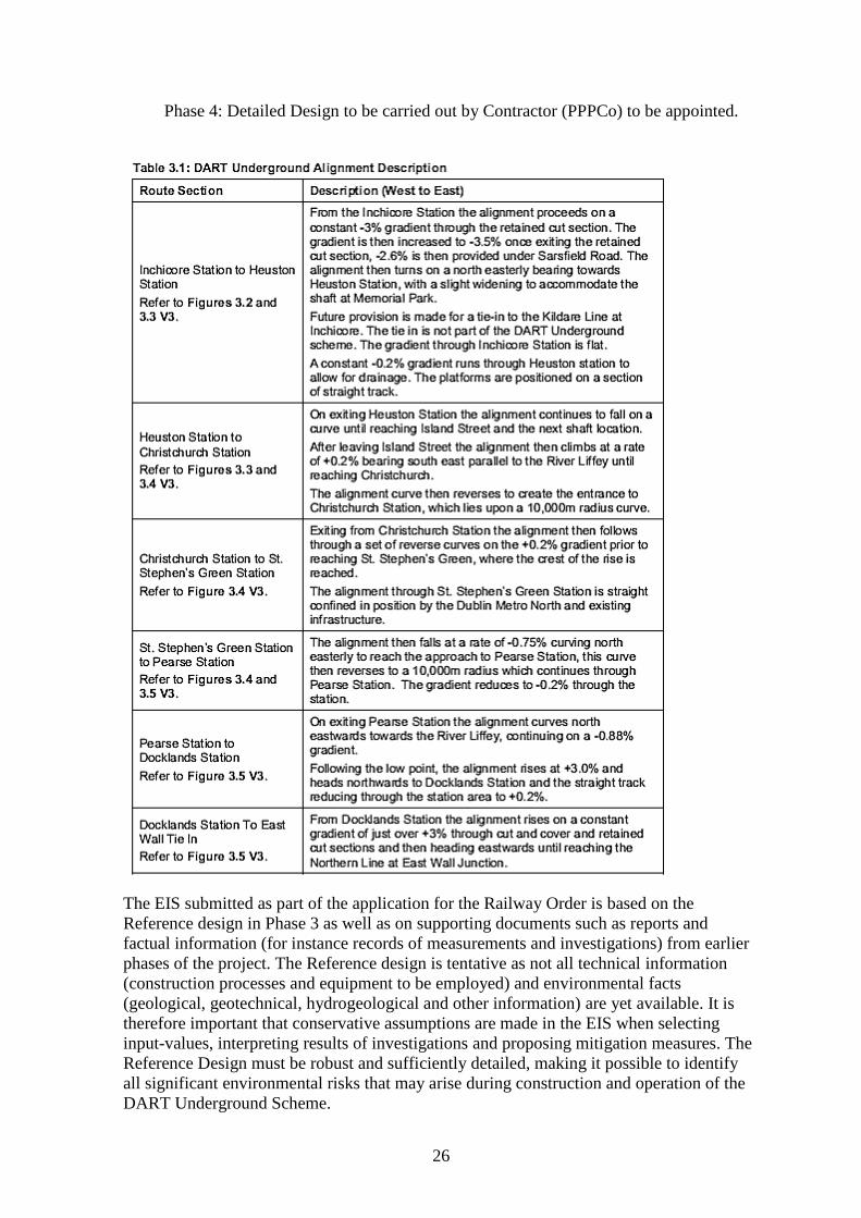
26
Phase 4: Detailed Design to be carried out by Contractor (PPPCo) to be appointed.
The EIS submitted as part of the application for the Railway Order is based on the
Reference design in Phase 3 as well as on supporting documents such as reports and
factual information (for instance records of measurements and investigations) from earlier
phases of the project. The Reference design is tentative as not all technical information
(construction processes and equipment to be employed) and environmental facts
(geological, geotechnical, hydrogeological and other information) are yet available. It is
therefore important that conservative assumptions are made in the EIS when selecting
input-values, interpreting results of investigations and proposing mitigation measures. The
Reference Design must be robust and sufficiently detailed, making it possible to identify
all significant environmental risks that may arise during construction and operation of the
DART Underground Scheme.
27
In Phase 4, the Detailed Design shall be based on additional, extensive investigations
applying more sophisticated methods of analyses. The Detailed Design will be carried out
by the PPP Contractor or Design and Build Contractor (Contractor), with the Applicant
overseeing and auditing the design with respect to environmental risks. Modification of the
DART Underground Scheme during the Detailed Design and construction work are not
permitted to exceed the environmental requirements, restrictions and limitations stated in
the Railway Order.
The Detailed Design will be influenced by details not yet available at the time of the Oral
Hearing, such as specific construction methods and equipment to be chosen by the
Contractor. Also, design will be more robust as detailed information from further
geotechnical and geological investigations will become available. Therefore, it is necessary
that the environmental impact is constantly reviewed and updated as new information
becomes available.
The adherence of the Contractor to, and the enforcement of, environmental impact limits
will ultimately be the responsibility of the Applicant.
2.11 Structure of the Report
This report is divided into the following chapters. Headings and numbering do not follow
the order of chapters in the EIS:
Chapter 4: Environmental Impact Statement
Chapter 5: Environmental Risk Management
Chapter 6: Building Damage Classification
Chapter 7: Property Protection Scheme
Chapter 8: Construction Aspects
Chapter 9: Soils and Geology
Chapter 10: Hydrogeological Conditions
Chapter 11: Geotechnical Conditions
Chapter 12: Vibration and Groundborne Noise.
Each chapter starts with an introduction containing general information. Thereafter, the
specific environmental issues are presented, including factual information from the EIS
and results of investigations in supporting documents or evidence provided during the Oral
Hearing. At the end of each chapter, comments and recommendations are given with
respect to environmental impact for consideration by the Board.
The report includes also five Appendices:
Appendix 1: Order of Proceedings of the Oral Hearing
Appendix 2: Submissions and Evidence received prior to and during the Oral
Hearing
Appendix 3: Considerations Regarding Management of Environmental Risks
Appendix 4: Review of Submissions and Evidence to Oral Hearing.
Appendix 5: Inventory of Vibration and Groundborne Noise Guidelines and
Standards for Railway Tunnels.

28
The content of the appendices has been taken into consideration when evaluating the EIS
as well as the information presented during the Oral Hearing. Of particular relevance is
Appendix 4 where all submissions made prior to and/or during the Oral Hearing are briefly
summarised (with reference to Appendix 2) and review comments are given.
29
3 Environmental Impact Statement (EIS)
3.1 General
The EIS which accompanied the application for a Railway Order describes the potential
impacts on the environment which may result from the proposed construction, operation
and maintenance of the DART Underground. The objective of the EIS is to:
identify the likely significant environmental impacts of DART Underground during
the construction and operational phases giving regard to the characteristics of the
local environment,
evaluate the magnitude and significance of likely impacts and to propose
appropriate measures to mitigate potential adverse impacts.
3.2 Structure and Contents of EIS
The EIS was issued in June 2010 and comprises the following documents:
Volume 1: Non-Technical Summary
Volume 2: Main text of the EIS (comprised of 4 Books)
Volume 3: Figures (comprised of 4 books)
Volume 4: Appendices.
In Volume 2, each aspect of the environmental impact is described in a separate chapter
under the following headings:
Introduction
Assessment Methodology
Baseline Environment
Predicted Impacts
Mitigation Measures
Residual Impacts.
The below chapters of Volume 2, respective figures (Volume 3) and Appendices (Volume
4) were of particular relevance for the preparation of this report:
Chapter 5 – Construction Strategy
Chapter 8 – Noise and Vibration: Above Ground
Chapter 9 – Noise and Vibration: Below Ground
Chapter 13 – Soils and Geology
Chapter 14 – Hydrogeology
Chapter 15 – Hydrology
Chapter 16 – Settlement of Permanent Structures and Utilities
Chapter 20 – Architectural Heritage
Chapter 23 – Human Health
Chapter 24 – Cumulative Impacts and Interaction of Effects.
30
3.3 Comments and Recommendation on Structure of EIS
1. The structure of the EIS is logical and addresses environmental issues which can arise in connection with a major infrastructure project. However, information regarding environmental risk management, and how risk management concepts were implemented during its preparation, are missing.
2. Vague statements such as “in so far as is reasonably practicable” shall be avoided when stating impact criteria.
3. Factual information included in the EIS (e.g. results of site investigations) was reported without interpretation.
4. Although it is recognised that some aspects of environmental risk assessment can be commercially or contractually sensitive, this does in my view not justify that the description of fundamental aspects of environmental risk assessment was omitted.
5. Evidence provided by the Applicant during the Oral Hearing confirmed that strict environmental risk management procedures will be applied.
31
4 Environmental Risk Management
4.1 Methodology
At this stage of the DART Underground project, not all information about different aspects
of the proposed Scheme is known. Risk management can be described as: “the art of
making judgements in the absence of complete information”, a situation which is typical
for many major construction projects. Environmental considerations are becoming
increasingly important when evaluating the benefits and negative consequences of major
infrastructure projects and more stringent environmental requirements have been adopted
on recent projects in many countries. The DART Underground Scheme is intended to meet
high international standards and therefore, modern and strict environmental risk
management concepts, which are used on similar projects elsewhere, should also be
applied in the planning, design, execution and operation of this project. A brief discussion
of environmental risk management is presented in Appendix 3.
The process of environmental risk management can be divided into the following steps:
1. Risk Assessment: identify environmental hazards which have the potential to
cause negative impact from project activities (during construction and/or operation
phase). Assess risks by combining likelihood (probability) and consequences of
hazards for various project scenarios (managed by risk register). Risks shall be
expressed in quantitative terms and shall be based on conservative assumptions,
also considering unlikely events with significant consequences. Method statements
shall be prepared for all activities which have the potential of environmental
hazards.
2. Limiting Values: state quantifiable limiting values based on internationally
accepted criteria from best practice. Where such information does not exist, use
observational method in combination with local experience to establish limiting
values.
3. Monitoring: develop, implement and maintain field measurement systems to
monitor threshold (trigger) and limiting values. Inspect structures and survey
buildings to monitor construction impact. The Property Protection Scheme is an
example of prescribing limiting values based on damage criteria. Full-scale testing
and monitoring of construction activities provide a basis for establishing limiting
values (e.g. settlement, groundborne noise or damage to structures).
4. Compliance Control: by Independent Environmental and Archaeological Monitor
(E&AM) to verify that the Contractor and the Applicant comply with requirements
set out in the Railway Order and as documented in a “live” risk register. The
Applicant shall be ultimately responsible for implementation of Environmental
Risk Assessment throughout the lifetime of the project. The Contractor shall
prepare an action plan including measures to modify construction methods and
apply mitigation when trigger values and/or limiting values are exceeded, cf.
Appendix 3, Observational method.
4.2 Environmental Risk Assessment
In order to assure that the environmental goals set out in a Railway Order are actually
achieved during the different phases of the project, it is crucial that a mechanism is put in
place which on a continuous basis verifies that environmental requirements are actually
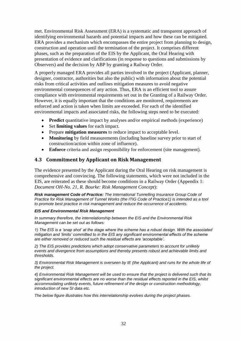
32
met. Environmental Risk Assessment (ERA) is a systematic and transparent approach of
identifying environmental hazards and potential impacts and how these can be mitigated.
ERA provides a mechanism which encompasses the entire project from planning to design,
construction and operation until the termination of the project. It comprises different
phases, such as the preparation of the EIS by the Applicant, the Oral Hearing with
presentation of evidence and clarifications (in response to questions and submissions by
Observers) and the decision by ABP by granting a Railway Order.
A properly managed ERA provides all parties involved in the project (Applicant, planner,
designer, contractor, authorities but also the public) with information about the potential
risks from critical activities and outlines mitigation measures to avoid negative
environmental consequences of any action. Thus, ERA is an efficient tool to assure
compliance with environmental requirements set out in the Granting of a Railway Order.
However, it is equally important that the conditions are monitored, requirements are
enforced and action is taken when limits are exceeded. For each of the identified
environmental impacts and associated risks, the following steps need to be executed:
Predict quantitative impact by analyses and/or empirical methods (experience)
Set limiting values for each impact.
Prepare mitigation measures to reduce impact to acceptable level.
Monitoring by field measurements (including baseline survey prior to start of
construction/action within zone of influence).
Enforce criteria and assign responsibility for enforcement (site management).
4.3 Commitment by Applicant on Risk Management
The evidence presented by the Applicant during the Oral Hearing on risk management is
comprehensive and convincing. The following statements, which were not included in the
EIS, are reiterated as these should become conditions in a Railway Order (Appendix 1:
Document OH-No. 21, R. Bourke: Risk Management Concept):
Risk management Code of Practice: The International Tunnelling Insurance Group Code of Practice for Risk Management of Tunnel Works (the ITIG Code of Practice1) is intended as a tool to promote best practice in risk management and reduce the occurrence of accidents.
EIS and Environmental Risk Management
In summary therefore, the interrelationship between the EIS and the Environmental Risk Management can be set out as follows:
1) The EIS is a ‘snap shot’ at the stage where the scheme has a robust design. With the associated mitigation and ‘limits’ committed to in the EIS any significant environmental effects of the scheme are either removed or reduced such the residual effects are ‘acceptable’.
2) The EIS provides predictions which adopt conservative parameters to account for unlikely events and divergence from assumptions and thereby presents robust and achievable limits and thresholds.
3) Environmental Risk Management is overseen by IE (the Applicant) and runs for the whole life of the project.
4) Environmental Risk Management will be used to ensure that the project is delivered such that its significant environmental effects are no worse than the residual effects reported in the EIS, whilst accommodating unlikely events, future refinement of the design or construction methodology, introduction of new SI data etc.
The below figure illustrates how this interrelationship evolves during the project phases.
33
4.4 Limiting values
The determination of quantifiable limiting values is essential for implementation of an
EIA. One major deficiency of the EIS is that it lacks in several sections definite and
verifiable limiting values of environmental impacts. In several chapters, the following
ambiguous phrase or similar expressions are used: “in so far as is reasonably practicable”.
The following are examples of statements in the EIS which are not acceptable for
environmental monitoring and control1:
8.6 Mitigation Measures - Above Ground Noise & Vibration
The Noise and Vibration Control Plans which will be based on and include method statements for each area of the works, the associated specific measures (to be at least those from the NVMP) to minimise noise and vibration in so far as is reasonably practicable for the specific works covered by each plan and a detailed appraisal of the resultant construction noise and vibration generated.
9.5 Mitigation Measures - Groundborne Vibrations The design development of the base scheme and its alignment has included the need to reduce environmental impact in so far as is reasonably practicable.
9.5.1. Construction - General
Prior to the commencement of any works on site, the Contractor will implement a mitigation strategy (at source – for all DART Underground noise and vibration sources - or receptor) at Marconi House, Gaiety Theatre and Grand Canal Theatre in order to reduce or remove, in so far as is reasonably practicable, the adverse groundborne noise effects from DART Underground works during critical operational times (e.g. performance, broadcast and critical rehearsal times).
9.5.1.2. TBMs
The Contractor will be obliged to implement a mitigation strategy (at either source or receptor) for the significant adverse effect on residential properties at Inchicore; Marconi House; Gaiety Theatre; and Grand Canal Theatre, in order to reduce or remove, in so far as is reasonably practicable, the adverse groundborne noise effect at night time for residential properties and during critical operational times (e.g. performance broadcast and critical rehearsal times) for non-residential property.
9.5.1.3.9. TBM Supply Trains
1 Numbering in accordance with EIS; emphasis of underlined quotes added.
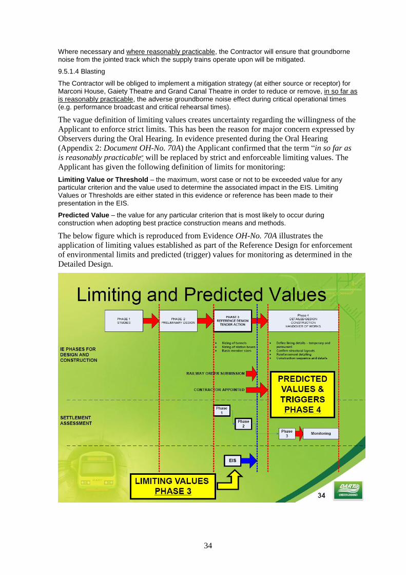
34
Where necessary and where reasonably practicable, the Contractor will ensure that groundborne noise from the jointed track which the supply trains operate upon will be mitigated.
9.5.1.4 Blasting
The Contractor will be obliged to implement a mitigation strategy (at either source or receptor) for Marconi House, Gaiety Theatre and Grand Canal Theatre in order to reduce or remove, in so far as is reasonably practicable, the adverse groundborne noise effect during critical operational times (e.g. performance broadcast and critical rehearsal times).
The vague definition of limiting values creates uncertainty regarding the willingness of the
Applicant to enforce strict limits. This has been the reason for major concern expressed by
Observers during the Oral Hearing. In evidence presented during the Oral Hearing
(Appendix 2: Document OH-No. 70A) the Applicant confirmed that the term “in so far as
is reasonably practicable” will be replaced by strict and enforceable limiting values. The
Applicant has given the following definition of limits for monitoring:
Limiting Value or Threshold – the maximum, worst case or not to be exceeded value for any particular criterion and the value used to determine the associated impact in the EIS. Limiting Values or Thresholds are either stated in this evidence or reference has been made to their presentation in the EIS.
Predicted Value – the value for any particular criterion that is most likely to occur during construction when adopting best practice construction means and methods.
The below figure which is reproduced from Evidence OH-No. 70A illustrates the
application of limiting values established as part of the Reference Design for enforcement
of environmental limits and predicted (trigger) values for monitoring as determined in the
Detailed Design.
35
4.5 Monitoring
Monitoring has a central role in environmental risk management. The following definition
of Monitoring is given in the Glossary of the EIS:
Monitoring: The repetitive and continues observation, measurement and evaluation of environmental data to follow changes over a period of time to assess the efficiency of control measures.
However, the EIS does not discuss the role of monitoring as part of the environmental
impact assessment process. Due to lack of information on monitoring, the Applicant was
requested to provide detailed evidence with description of how to implement
environmental impact monitoring throughout the project and in particular the overall
strategy for monitoring during construction of the DART Underground.
4.5.1 Applicant’s Evidence on Monitoring
In response to the questions by the Inspector and ABP experts, extensive evidence was
presented by the Applicant on field monitoring. The following section summarises the key
issues which were addressed in the evidence by the Applicant (OH-No. 70A):
This evidence summarises the project’s instrumentation and monitoring obligations relating to the verification of design, construction process control, environmental monitoring and third party asset protection.
Instrumentation and Monitoring Strategy describes why monitoring is an essential element of the risk management strategy for construction of DART Underground and also confirms the monitoring provision.
Instrumentation and Monitoring Methods describe the instrumentation and methods to be deployed to capture the field data during construction relating to the various elements of DART Underground.
Instrumentation and Monitoring Framework sets out the manner in which monitoring data will be processed and made readily available to those who need access to be in a position to respond to that data if required.
Action and Response to Observations outlines the protocol of trigger values set against the Limiting Values identified in the EIS.
The Applicant confirmed the instrumentation and monitoring strategy and monitoring
requirements previously presented in the evidence dealing with the following aspects:
Construction Strategy
Risk Management Concepts
Geotechnics, Soils and Geology
Settlement of Permanent Structures and Utilities
Property Protection Scheme
Hydrogeology
Below Ground Noise and Vibration
Above Ground Noise and Vibration
Air Quality
Hydrology
Traffic.
The evidence describes methods of instrumentation and monitoring to verify the predicted
impacts. Reference is made to Appendix 2: Document OH-No. 70A.
The Contractor will be required to undertake monitoring as follows:
36
Construction Phase Monitoring
Noise and Vibration monitoring for above and below ground works
Ground settlement monitoring
Condition monitoring for buildings (during blasting etc.)
Dust deposition monitoring
Occupational monitoring programme the tunnel
Groundwater level and quality monitoring (also to take account of features dependent on groundwater abstractions and archaeological features)
Surface water quality monitoring
Archaeological monitoring
Monitoring of waste and materials leaving DU sites (as part of waste audit)
Traffic monitoring as part of Construction Traffic Management Plan
Monitoring of Resident car parking
The proposed Environmental and Architectural Monitor (E&AM) will validate all monitoring and undertake check monitoring as required independent of the Contractor.
Operational Phase Monitoring
Vehicle and pedestrian monitoring (in the vicinity of stations)
Cycle parking utilisation
Surface and groundwater monitoring (specified for 3 and 24 months post-construction, respectively)
Monitoring of Resident car parking around Inchicore and Pearse
The Applicant summarised the obligations regarding monitoring as follows:
This evidence has summarised the project’s instrumentation and monitoring obligations relating verification of design, construction process control, environmental monitoring and third party asset protection. The monitoring strategy and framework will provide an effective instrumentation and monitoring regime by ensuring that:
Baselines are established against which measurements can be compared.
There are unambiguous responsibilities to ensure that all data gets captured and interrogated as planned.
There is a framework in place to allow for efficient reading, recording, processing and communication of data so that the people who need the data to make decisions regarding construction activities have the necessary data available in a format that can be readily interpreted and understood.
Risks of exceedance [sic] are minimised by early warning of emerging trends.
There is clarity of definition of Trigger and Limiting Values and clear responsibility for action if Trigger Values are exceeded.
Reliability of data, such that those using the data have confidence in its accuracy. This requires the ability to verify the data if necessary e.g. primary and secondary monitoring
The evidence has presented instrumentation and monitoring strategy that will be delivered within a robust management framework to ensure that the principal aims of monitoring are achieved for DART Underground as follows:
Design verification and construction process control
Environmental monitoring
Third party asset protection
37
In conclusion, for the overall monitoring strategy to be effective it must not involve any decisions based on subjectivity and it has to focus on the impacts of construction that can be easily measured and communicated to, and therefore readily understood by, the site teams. Most importantly the impact must be easy to define and measure.
The clarification obtained during the Oral Hearing by the Applicant on field
instrumentation and monitoring was important and complies with high standards. If
implemented as described, field monitoring will assure compliance with environmental
impact mitigation measures. Thus, many justified concerns of Observers expressed in
submissions can be alleviated.
4.5.2 Compliance Control
According to the EIS, compliance with the requirements will be assured by construction
site management as outlined in the EIS, Chapter 5 (Construction Strategy):
5.22. Construction Health and Safety 5.22.3.1. Construction Site Management
There will be a Contractor management team on site for the duration of the construction phase. The team will supervise the construction of the Works including monitoring the Contractors performance to ensure that the proposed construction phase mitigation measures are implemented and that construction impacts and nuisance are minimised.
However, this commitment in the EIS does not describe in sufficient detail how
independent compliance control is assured during construction and operation of the DART
Underground. Therefore, the Applicant was requested to present clarification and evidence
regarding the obligations for compliance control.
The Applicant presented the management framework with obligations to assure
compliance and enforcement of environmental requirements (OH-No. 70A):
Management Framework
As set out previously in Mr. Mark Conroy’s evidence, CIÉ/IÉ will retain all obligations, including the Environmental & Archaeological obligations, imposed on them by the Railway Order (including the EIS) during the construction and operational phases of the DART Underground Project.
Environmental Management Plan & Monitoring
In order to manage and control the overall Environmental and Archaeological risk exposure to the Project, CIÉ/IÉ is proposing that the Contractor develop an Environmental Management Plan in accordance with the EIS. CIÉ/IÉ is committed to assuring compliance with the Railway Order (including the EIS) and therefore:
1. An independent Environmental & Archaeological Monitor (E&AM) will be appointed jointly by CIÉ/IÉ and the Contractor. The proposed E&AM will report on the compliance of the Contractor with the commitments in the Environmental Management Plan its daughter plans (e.g. Noise & Vibration Management Plan and Noise & Vibration Control Plans) and Railway Order.
2. CIÉ/IÉ will engage a team of engineers and environmental scientists and a project archaeologist to review data submitted by the Contractor, liaise with authorities and interested parties, and monitor the performance (technically and environmentally) of the Contractor.
3. An Independent Certifier (IC) will be appointed jointly by CIÉ/IÉ and the Contractor. The proposed IC will independently monitor and report on all the design, procedures and construction etc. either carried out or implemented by the Contractor.
Non-compliance Issues and Breaches
The Contractor will establish and implement environmental monitoring throughout the project. The methodology will be sanctioned by the E&AM and the CIÉ/IÉ team of engineers and environmental scientists. The Contractor’s monitoring results will be issued to both CIÉ/IÉ and the E&AM for assessment. CIÉ/IÉ and the E&AM will also undertake sample monitoring to verify the Contractor’s process and monitoring results. As set out previously in Mr. Mark Conroy’s evidence, all validated
38
monitoring data will be made available to any interested parties in a manner and format that is easily accessible.
The Contractor will be contractually compelled to immediately inform CIÉ/IÉ and the E&AM of any circumstances which may give rise to non-compliance and breaches of the imposed conditions and obligations set out under the Railway Order and the PPP Contract.
The Contractor will be responsible for promptly implementing whatever action is required to remedy the issue that has arisen. CIÉ/IÉ, the E&AM and the IC will have the right to access the site and carry out audits of the systems and the works at any time during the construction of the project.
If an act or default of the Contractor or a related party has caused, or is likely to cause, CIÉ/IÉ to be in breach of their obligations under the Railway Order then CIÉ/IÉ will have the right under the PPP Contract to suspend the whole or part of the works. The suspensions will be issued by CIÉ/IÉ or their appointed representatives and last until an effective remedy has been approved and put into place by the Contractor.
Action and Emergency Response Plans
The I&M Plans will be developed into the following documents:
Action Plans will be prepared by the Contractor to develop the actions to be taken in response to monitoring data and breaches of trigger values. Action Plans will be required to address the planned response to breaches of all three trigger levels (green, amber and red).
Emergency Response Plans will be developed in conjunction with Asset Owners and will detail the planned response to Back Trigger values.
The Contractor shall ensure that resources necessary to take the defined actions are available so that Action Plans and Emergency Response Plans can be implemented promptly. In addition, emergency drills should be identified and undertaken.
The monitoring data related to each element of the Works shall be reviewed on each shift by the Shift Review Group (SRG) for each construction site and tunnel drive. The SRG, outlined in red on this slide of the Project Management Framework, will typically comprise:
Contractor: Senior Engineer/Environmental Manager for work being undertaken, Senior Monitoring Engineer.
Contractor’s Designer: Senior Design Engineer
Independent Environmental and Archaeological Monitor (E&AM): Senior Field Engineer
CIE Works Review Team: Senior Engineer.
4.6 Applicant’s Commitments to ERA
Note 1 of the Agenda for the Oral Hearing requested clarification how environmental risk
assessment concepts are being applied to DART Underground. Specific environmental risk
assessment concepts used were addressed by the relevant technical experts in their
respective briefs:
• Below ground noise and vibration, R. Greer
• Above ground noise and vibration, J. Harmon
• Soils and geology, S. Mason
• Settlement, S. Fricker
• Hydrogeology, K. Cullen, and
• Construction strategy, K. McManus.
During Module 1, the Applicant confirmed his commitment to the implementation of
environmental risk management:
39
4.6.1 Risk Management (M. Conroy, Evidence OH-No. 5):
There has been significant interaction between design engineers and environmental specialists contributing to the EIS; and also between the multi-disciplinary consultants and CIÉ/Iarnród Éireann. This interaction led to design iteration and refinement that culminates in the DART Underground design presented in the Railway Order Application. The environmental assessments undertaken for the EIS and the environmental risk management of the DART Underground design are parallel and supporting processes.
The environmental assessments undertaken for the EIS and the environmental risk management of the DART Underground design are parallel and supporting processes.
Subject to approval of the Railway Order, CIÉ/Iarnród Éireann commits to continued use of the risk management concepts throughout the life of the project. This will include auditing and enforcing risk management for the duration of the project. As the project proceeds, CIÉ/Iarnród Éireann will appoint a Risk Manager as part of the CIÉ/Iarnród Éireann team for the Detailed Design Stage and Construction Design Stage to manage the auditing and enforcement of the risk management programme.
CIÉ/Iarnród Éireann will employ a team of engineers and scientists to manage the risk management programme, to review all data from the detailed design and construction stages, to liaise with authorities and interested parties and to audit the performance of the works.
4.6.2 Construction Strategy, Scheduling & Programming (K. McManus, Evidence OH-No.18)
With regard to risk management in relation to construction strategy, the following assurances were given:
The concepts utilised to identify the environmental risk of construction are generally those outlined in ‘A Code of Practice for Risk Management of Tunnel Works’ prepared by the International Tunnelling Insurance Group 2006.
Multidisciplinary design iterations and reviews have been conducted throughout the project development stage, resulting in the refinement of design and construction direction described by Mr. C. Lavery and the Risk Management process to be described by Mr. Roland Bourke.
Furthermore, the hazards identified, the risks assessed at specific locations along the project and the mitigation or contingency measures identified by the various discipline specialists have been assimilated in conjunction with the design engineers into the development of construction methodologies, particularly those below ground. As part of this process, the feasibility of a regime of contingent methodologies has been established to cater for the spectrum of hazards identified through site and ground investigation and also across the range of likelihoods of the related risks coming to pass.
The EIS, which forms in large part the submission currently before the Board, has been prepared using concepts founded in risk management and propounded by authoritative international bodies, with the objective of mitigating the impacts of construction of DART Underground to those as low as reasonably practicable.
4.6.3 Oral Hearing Closing Statement (P. Muldoon, Evidence OH-No. 249)
Risk Management for DART Underground is being undertaken within a Risk Management Framework which will extend from project inception through the life of the project.
The approach adopted by DART Underground is consistent with international best practice including the ‘Code of Practice for Risk Management of Tunnel Works’ prepared by the International Tunnelling Insurance Group (ITIG) in 2006.
The development of the EIS and Environmental Risk Management are parallel and supporting processes. The EIS preparation, as I said earlier, is an iterative process, which links into both design development and the first stage of the ongoing environmental risk management process. Moreover, the Environmental Impact Assessment culminates in the granting of a Railway Order, whilst the Environmental Risk Management process continues for the life of the project.
During the construction phase, information will be obtained that will inform further iterations of the
40
environmental risk assessment, including noise and vibration monitoring for above and below ground works; ground settlement monitoring; condition monitoring for buildings and groundwater level monitoring. The monitoring results will be continually reviewed against both the limits set out in the EIS and any updated predictions. On this basis the ongoing assessment of risk will always be based on current information.
4.7 Comments and Recommendation – Environmental Risk Management
The EIS contained insufficient information on how environmental risks associated with the
DART Underground Scheme shall be managed during design, construction and operation.
In response to the request for clarification in Note 1 and to questions during the Oral
Hearing, the Applicant has presented comprehensive and convincing evidence on risk
management.
Mr. Bourke presented a detailed description of the Risk Management Concept (Evidence
OH-No. 2, Risk Management Concept, Roland Bourke, Property Controls Manager) on
which the EIS is based. It was confirmed that, although this aspect was not emphasised in
in the EIS, close interaction and discussion of environmental issues took place between
different technical disciplines.
Mr. Fricker presented a comprehensive document describing field monitoring (Evidence
OH-No. 70A) and clarifications regarding limiting values, field monitoring and compliance
control. This document describes in great detail how monitoring issues will be applied.
In his closing statement (Evidence OH-No. 249, Oral Hearing Closing Statement P.
Muldoon) Mr. Muldoon confirmed the commitment of the Applicant to the implementation
of a comprehensive risk management framework. This in my view satisfies high
international requirements of risk management. The assurances given by the Applicant will
have great significance for the safe implementation of the DART Underground Scheme
and shall help to alleviate the concerns expressed by many Observers.
In summary, Environmental Risk Management, for both constructional and operational
stages, shall be as indicated by the applicant in the ‘Brief of Evidence – Risk Management
Concept’ submitted to the Oral Hearing into the Railway Order application on the 1st day
of December 2010, ‘Brief of Evidence – Monitoring’ submitted to the Oral Hearing on the
14th
day of January 2011 and ‘Oral Hearing Closing Statement’ submitted to the Oral
Hearing on the 8th
day of April 2011.
The following comments and recommendations are made:
1. In response to the request for clarification in Note 1 of the Order of Proceedings and questions during the Oral Hearing, the Applicant has presented comprehensive evidence on risk management.
2. Rigorous risk management shall be applied during construction and operation of the DART Underground. Construction work which can cause environmental impacts shall be monitored carefully.
3. Monitoring of buildings and other structures or installations shall be carried out on a regular basis, results shall be viewed by experts with competence to evaluate and interpret the type of measurement. These interpreted results shall be made available to the public on a weekly basis.
4. Evidence on field instrumentation and monitoring was extensive and of high standard. The Applicant has stated the commitment that extensive field monitoring will be implemented to assure compliance with environmental impact criteria.

41
5. Monitoring of buildings shall be carried out on a regular basis. Results shall be reviewed by experts with competence to evaluate and interpret the type of measurement. These interpreted results shall be made available to the public, preferably on a weekly basis.
6. Annual compliance monitoring shall be carried out during the operational phase to assure that the DART Underground Scheme is properly maintained.
42
5 Building Damage Classification
5.1 General Considerations
Construction of infrastructure projects such as the DART Underground in and below an
urbanised area with sensitive receptors has the potential of causing inconvenience to
humans and damage to buildings, structures and installation and below the ground as well
as utilities and infrastructure. While it is impossible to avoid inconvenience during limited
periods of construction, efforts must be made to avoid or at least to keep damage to
buildings and other structures to a minimum. Environmental risk management is the most
efficient approach of avoiding potential risks to buildings. Identification of a risk zone
along the alignment and extensive monitoring are essential elements. The consequences of
construction work leading to building damage are of major concern to the public and this
issue was raised by many Observers during the Oral Hearing.
The city centre of Dublin is the home of important architectural and cultural heritage. Such
buildings are particularly sensitive to environmental impact and can suffer from
construction activities, if not properly planned, designed and executed.
5.2 Description of Building Damage
The EIS addresses building damage in Chapter 16, Settlement of permanent structures and
utilities. Chapter 16.2.4.1 presents in Table 16.1 a method of characterising building
damage based on ease of repair. It should be noted that this classification system is not
limited to damage from settlement but also to other impacts such as vibrations, variations
of groundwater, temperature changes etc.
The basic concept of “ease of repair” is widely accepted among engineers and has been
applied on many infrastructure projects. However, this concept is often misunderstood by
the public as it is interpreted as an interpretation of the significance of damage to
occupants of buildings. The proposed damage classification system is related to the cost of
repair and does not address the subjective experience that a property owner may have when
detecting cracks in a wall.
It is important to note that this table shall not be applied without careful consideration of
specific requirements to buildings of architectural heritage where even minor cracks can
require significant repair work.
For conventional buildings an important dividing line is between damage Category 2 (Very
slight) and Category 3 (Slight). If damage exceeds Category 2, this is usually associated
with significant ground movement and the causal relationship between construction
activity and observed damage becomes easier to identify.
The objective of ERA and of the proposed monitoring scheme is to avoid that building
damage exceeds Damage Category 2. This can be achieved by keeping the Contractor(s)
informed should any cracks corresponding to Damage Category 2 develop in buildings.
When monitoring and inspection of buildings indicates that damage has been sustained
corresponding to Building Category 2, the Contractor shall be informed immediately. The
method statement for construction work in the vicinity of affected buildings shall be
reviewed in cooperation with the Applicant’s team and the E&AM. The Contractor shall be
required to take immediate action in order to avoid further damage to occur.
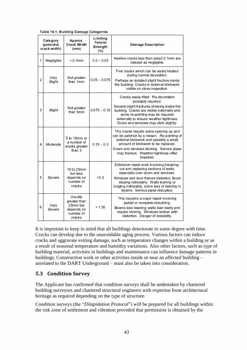
43
It is important to keep in mind that all buildings deteriorate to some degree with time.
Cracks can develop due to the unavoidable aging process. Various factors can induce
cracks and aggravate exiting damage, such as temperature changes within a building or as
a result of seasonal temperature and humidity variations. Also other factors, such as type of
building material, activities in buildings and maintenance can influence damage patterns in
buildings. Construction work or other activities inside or near an affected building –
unrelated to the DART Underground – must also be taken into consideration.
5.3 Condition Survey
The Applicant has confirmed that condition surveys shall be undertaken by chartered
building surveyors and chartered structural engineers with expertise from architectural
heritage as required depending on the type of structure.
Condition surveys (the “Dilapidation Protocol”) will be prepared for all buildings within
the risk zone of settlement and vibration provided that permission is obtained by the
44
property owner. Conditions surveys will also be supplemented by installation of different
types of monitoring equipment, where possible and permitted by the property owner.
Condition surveys shall be carried out in the presence of the property owner. The
dilapidation protocol shall be counter-signed by the property owner and any disputes shall
be referred to an arbitrator according to the procedures outlined in the manual prepared for
the implementation of the Property Protection Scheme.
The condition survey will cover each room in a building, examine each wall, each ceiling,
and each floor, with the aim to record any defects. Cracks and other defects will be
recorded on drawings; photographs will be taken and any cracks will be given a category
number, given a category number in accordance with the Building Research Establishment
Digest 251. That digest contains a table which is similar to the Building Damage
Categories. The condition survey will also contain a number of photographs associated
with each defect that is visible. The information on building survey contained in the
following reports should also be considered: BRE Digest 343, Simple measuring and
monitoring of movement in low-rise buildings – Part 1: cracks, (1989) and BRE Digest
344, Simple measuring and monitoring of movement in low-rise buildings - Part 2:
settlement, heave and out-of-plumb, (1995).
With respect to damage due to vibrations and shocks, the following standard should be
used as minimum requirement: British Standards (BS) 7385-2; Evaluation and
measurement for vibration in buildings - Part 2: Guide to damage levels from
groundborne vibration, (1993); Annex A, B and C.
It should be noted that in special cases (historic buildings, sensitive structures, installations
in the ground etc.), the extent and type of the condition survey must be adapted to the
specific requirements. For instance, utilities shall be inspected carefully at critical
(vulnerable) sections, combined with surveying and monitoring.
5.4 Comments and Recommendation – Building Damage Classification
1. The proposed building damage classification system is widely accepted and suitable for the project. Building damage exceeding Damage Category 2 shall be avoided. Trigger levels of the monitoring scheme shall be set not to exceed damage Category 2, and Category 1 for historic buildings identified on the Record of Protected Structures, respectively.
2. A panel of independent chartered building surveying companies shall be established. Panel members shall be instructed by the Applicant about the requirements of building surveying.
3. Condition surveys shall be carried out for buildings within the risk zone of settlement and vibration (subject to consent of the property owner), these surveys shall be carried out prior to, during and after completion of the Dart Underground.
4. Trigger levels of the monitoring scheme for building damage shall be set not to exceed Category 1 for buildings/structures on the Record of Protected Structures and Category 2 for all other buildings. Should building damage corresponding to Category 1 for buildings/structures on the Record of Protected Structures or Category 2 for all other buildings occur an interim survey shall be carried out without delay. The contractor shall be required to modify or adjust the construction process to avoid any further damage. Changes to the working method shall be agreed with applicant and/or the Independent Environmental & Archaeological Monitor.

45
5. The contractor shall be required to engage the services of suitably qualified persons in the field of architectural heritage protection in relation to the carrying out of surveys, installation of monitoring instrumentation, interpreting monitoring data and determining appropriate repairs of any damage caused for buildings/structures on the Record of Protected Structures. The Independent Environmental & Archaeological Monitor shall also include persons suitably qualified in architectural heritage protection.
46
6 Property Protection Scheme
6.1 Objective
In order to assure owners of property located above or adjacent to the DART Underground
alignment protection against damage, the Applicant has set up Property Protection Scheme
(PPS). The PPS is described in Chapter 16.7 of the EIS and in a separate brochure issued
by the Applicant. During Module 1 of the Oral Hearing, the Applicant presented details of
the PPS (OH-No. 27; Mark Conroy: Property Protection Scheme).
Owners of property within a risk zone above or adjacent to the tunnel(s), shafts and
excavations (as defined by the predicted 1 mm settlement contour or 30m from the tunnel
centreline and 50m from shafts, whichever is the greater) are entitled to join the PPS.
Participation in the PPS does not infringe on any legal or other rights of the property
owner. The Applicant proposes that the Contractor assumes responsibility for the PPS. It
will remain in place for 12 months after completion of the underground works or longer in
the case settlement does continue.
The Applicant will establish a panel of three independent firms of building surveyors.
These firms will carry out an initial condition survey report (Dilapidation Protocol). After
construction, a final condition survey will be carried out and a second survey report will be
prepared.
If damage exceeding Category 2 is noted during construction of the DART Underground,
an assessment will be carried out by the building surveyor, resulting in an interim survey
report. If the interim survey and report recommends repairs to rectify the damage caused
by the DART Underground works, and those repairs cost up to € 30,000, the
recommendations will be implemented. In EIS, Chapter 16.2.2 (Basis of Assessment
Methodology) the following conditions are stated for historic buildings (protected
structures):
Any cosmetic impacts, such as minor cracking that may occur within buildings associated with a damage category of slight for general buildings and very slight for buildings that are on the Record of Protected Structures, will be repaired under the Property Protection Scheme.
It can be assumed that cost of repair of damage falling within Category 1 and 2 will be
below a limit of € 30,000. In the event of a dispute, the case will be referred to an
independent expert, selected from a panel established by the Institution of Engineers of
Ireland.
6.2 Clarification regarding Property Protection Scheme
During the Oral Hearing, the Applicant responded to questions from the Inspector, ABP
Experts and Observers. The Applicant was requested by the Inspector to prepare and
present a written document summarising evidence given at different occasions during the
Oral Hearing. The Applicant presented a detailed description of the PPS (OH – No. 73
Detail of the Dart Underground Property Protection scheme). The evidence is
comprehensive and helped to clarify many question raised during the Oral Hearing. The
Applicant confirmed the following key issues regarding the PPS:
1. The PPP Contractor or Design and Build Contractor will be required by its contract to implement the Property Protection Scheme.
2. Upon appointment, the PPP Company will undertake a detailed assessment of ground
47
movement/building settlement and vibration.
3. Nothing in the Property Protection Scheme detracts from, or dilutes, the legal rights of owners to claim for building damages against the DART Underground PPP Company.
4. The PPP Company must have insurance for their legal liabilities for building damage in excess of €30,000.
5. All building damage attributable to DART Underground works will be addressed, regardless of costs.
6. Building damage relates to direct damage to the structure of the building as a result of potential ground movement/settlement and from vibration and also damage to buildings as a result of damage to private utility spurs from local authority services.
7. The Property Protection Scheme will remain valid for:
12 months following completion of construction works; or, in the unlikely event that settlement has not stabilised within this period,
such longer time as is required to demonstrate that settlement has stabilised.
8. CIE/Iarnród Éireann will establish a panel of independent chartered building surveying companies or consulting civil/structural engineering firms. The pre-approval and formation of this panel will ensure a consistency in approach when conducting surveys under the Property Protection Scheme.
9. The Independent Expert will be selected from Engineers Ireland Panel of Conciliators. The decision of the Independent Expert is binding on the PPP Company.
10. The preliminary condition survey report will be issued to the property owner, the PPP Company, and CIE/Iarnród Éireann upon completion.
11. During the construction works, property owners may request an interim survey, should their building develop signs of deterioration.
12. As required and appropriate, based on heritage value or building sensitivities, a conservation architect will provide supplemental advice and input to the condition surveys.
13. Prior to commencement of construction and for the duration of construction, monitoring of Ground Movement/Building Settlement and Vibration will be conducted by the PPP Company. All monitoring will be reviewed, audited and validated by an Independent Environmental and Archaeological Monitor and a team of engineers/scientist employed directly by CIE/Iarnród Éireann.
14. The findings of any issues arising from interim condition surveys will feed into the monitoring data review process. This will provide an interaction between findings of the building condition surveys and the construction monitoring as DART Underground construction is proceeding.
15. The property owner may refer the matter to an Independent Expert, in the event that:
i. the findings of the surveyor are disputed; or
ii. the PPP Company's opinion is disputed in relation to cause of damage; or
iii. the PPP Company's opinion is disputed in relation to the valuation of rectification works; or
iv. the property owner disputes the fact that the damage has been rectified.
16. If the PPP Company fails to rectify damage attributed to DART Underground works, CIE/Iarnród Éireann has the right to intervene and have any matter arising addressed.
6.3 Comments and Recommendation – Property Protection Scheme
The EIS and the evidence given by the Applicant - in response to extensive questioning by
Observers and ABP Experts – have clarified the objectives, scope and limitation of the
PPS. The proposed PPS is an important step of taking into account the concerns of
48
property owners which potentially could be affected by construction of the DART
Underground. Therefore, the above evidence provided by the Applicant shall be made a
condition of the Railway Order.
Property Protection Scheme
1. The structure and content of the Property Protection Scheme shall be as indicated in ‘Property Protection Scheme – DART Underground Oral Hearing’ submitted by the applicant to the Oral Hearing on the 19th day of January 2011. The applicant shall retain overall responsibility for the implementation and operation of the Property Protection Scheme throughout the lifetime of the DART Underground (construction and operation).
2. The limit of € 30,000 stated in the EIS shall correspond to construction cost excluding VAT and, and shall be adjusted annually and shall be adjusted annually to reflect cost of working in the construction industry.
49
7 Construction Aspects This section addresses the construction methods and processes proposed for the DART
Underground Scheme.
7.1 Construction Strategy
A variety of construction activities will occur simultaneously at a number of different
locations along the DART Underground route. Shallow structures founded in the softer
ground will be open cut, with structures formed using diaphragm wall or secant pile
techniques. Since these structures lie outside the city centre and are extensive in nature,
they will be constructed “bottom up” and using bulk excavation. Central stations and shafts
will be founded deeper in the underlying rock. These must be mined. The initial openings
near the surface will be supported using secant piled walls. Thereafter, excavation will
proceed level by level in what is known as “top down” construction. The walls will be
supported by anchors or props. Rock is most likely to be broken in place using drill and
blast technology.
The core structures of the horizontal element of the project are the running tunnels. These
will traverse both hard and soft ground. Due to their length and uniformity, the tunnels will
be bored and lined using tunnel boring machines (TMBs). As a result of the mixed ground
conditions and the need to minimise settlement, Earth Pressure Balance Machines (EPMs)
have been selected as the most appropriate technology.
The running tunnels are to be constructed from the East Portal using two machines, one for
each bore. This method has been assessed as having least impact on the environment.
Cross-passages will be constructed using soil and rock excavation methods.
7.1.1 Programme of Works and Phasing
During the first 3 months of the DART Underground project main construction works have
been set aside for establishment of an initial design for the final works and the final design
procedures and acquisition of detailed local consents across the route. Exceptions to this
are the continuity of operations at Christchurch, following completion of the archaeology
excavation and the early start to construction at the East Portal and Docklands Station. This
is required to ensure that the structures are sufficiently advanced to accept passage of the
TBMs.
The next ten months of construction will see this pattern extend across much of the project,
with a phased start-up of piling and excavation at Pearse, St Stephen’s Green,
Christchurch, Island Street and Heuston. Site Preparation works will also start at the TBM
reception chambers in the CIE lands at Inchicore. The West Road bridge realignment will
be underway during this period.
Following launch of the first TBM, the second will start around 2 months later. By this
time too, excavation will be underway at Pearse, St Stephen’s Green, Christchurch and the
east shaft for Heuston. The TBMs will drive for around 22 months, which will also be the
most intense period of the project for excavation, with activity at locations along the route,
although at Inchicore station this will primarily be installation of piled retaining walls.
The fourth year of the project will see completion of all station and shaft excavation and
activity will become concentrated underground with the start of the platform enlargements,
serviced through the now completed running tunnels.
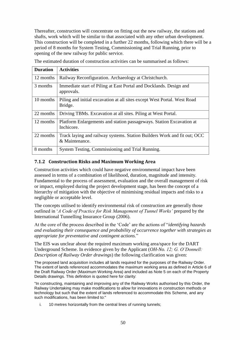
50
Thereafter, construction will concentrate on fitting out the new railway, the stations and
shafts, work which will be similar to that associated with any other urban development.
This construction will be completed in a further 22 months, following which there will be a
period of 8 months for System Testing, Commissioning and Trial Running, prior to
opening of the new railway for public service.
The estimated duration of construction activities can be summarised as follows:
Duration Activities
12 months Railway Reconfiguration. Archaeology at Christchurch.
3 months Immediate start of Piling at East Portal and Docklands. Design and
approvals.
10 months Piling and initial excavation at all sites except West Portal. West Road
Bridge.
22 months Driving TBMs. Excavation at all sites. Piling at West Portal.
12 months Platform Enlargements and station passageways. Station Excavation at
Inchicore.
22 months Track laying and railway systems. Station Builders Work and fit out; OCC
& Maintenance.
8 months System Testing, Commissioning and Trial Running.
7.1.2 Construction Risks and Maximum Working Area
Construction activities which could have negative environmental impact have been
assessed in terms of a combination of likelihood, duration, magnitude and intensity.
Fundamental to the process of assessment, evaluation and the overall management of risk
or impact, employed during the project development stage, has been the concept of a
hierarchy of mitigation with the objective of minimising residual impacts and risks to a
negligible or acceptable level.
The concepts utilised to identify environmental risk of construction are generally those
outlined in ‘A Code of Practice for Risk Management of Tunnel Works’ prepared by the
International Tunnelling Insurance Group (2006).
At the core of the process described in the ‘Code’ are the actions of “identifying hazards
and evaluating their consequence and probability of occurrence together with strategies as
appropriate for preventative and contingent actions.”
The EIS was unclear about the required maximum working area/space for the DART
Underground Scheme. In evidence given by the Applicant (OH-No. 12; G. O’Donnell:
Description of Railway Order drawings) the following clarification was given:
The proposed land acquisition includes all lands required for the purposes of the Railway Order. The extent of lands referenced accommodates the maximum working area as defined in Article 6 of the Draft Railway Order (Maximum Working Area) and included as Note 5 on each of the Property Details drawings. This definition is quoted here for clarity:
"In constructing, maintaining and improving any of the Railway Works authorised by this Order, the Railway Undertaking may make modifications to allow for innovations in construction methods or technology but such that the extent of lands referenced to accommodate this Scheme, and any such modifications, has been limited to:"
i. 10 metres horizontally from the central lines of running tunnels;
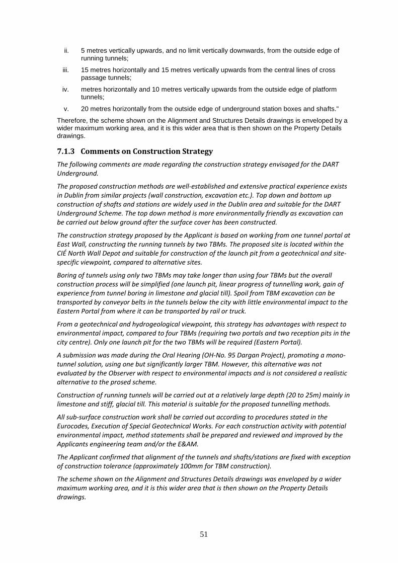
51
ii. 5 metres vertically upwards, and no limit vertically downwards, from the outside edge of running tunnels;
iii. 15 metres horizontally and 15 metres vertically upwards from the central lines of cross passage tunnels;
iv. metres horizontally and 10 metres vertically upwards from the outside edge of platform tunnels;
v. 20 metres horizontally from the outside edge of underground station boxes and shafts."
Therefore, the scheme shown on the Alignment and Structures Details drawings is enveloped by a wider maximum working area, and it is this wider area that is then shown on the Property Details drawings.
7.1.3 Comments on Construction Strategy
The following comments are made regarding the construction strategy envisaged for the DART Underground.
The proposed construction methods are well-established and extensive practical experience exists in Dublin from similar projects (wall construction, excavation etc.). Top down and bottom up construction of shafts and stations are widely used in the Dublin area and suitable for the DART Underground Scheme. The top down method is more environmentally friendly as excavation can be carried out below ground after the surface cover has been constructed.
The construction strategy proposed by the Applicant is based on working from one tunnel portal at East Wall, constructing the running tunnels by two TBMs. The proposed site is located within the CIÉ North Wall Depot and suitable for construction of the launch pit from a geotechnical and site-specific viewpoint, compared to alternative sites.
Boring of tunnels using only two TBMs may take longer than using four TBMs but the overall construction process will be simplified (one launch pit, linear progress of tunnelling work, gain of experience from tunnel boring in limestone and glacial till). Spoil from TBM excavation can be transported by conveyor belts in the tunnels below the city with little environmental impact to the Eastern Portal from where it can be transported by rail or truck.
From a geotechnical and hydrogeological viewpoint, this strategy has advantages with respect to environmental impact, compared to four TBMs (requiring two portals and two reception pits in the city centre). Only one launch pit for the two TBMs will be required (Eastern Portal).
A submission was made during the Oral Hearing (OH-No. 95 Dargan Project), promoting a mono-tunnel solution, using one but significantly larger TBM. However, this alternative was not evaluated by the Observer with respect to environmental impacts and is not considered a realistic alternative to the prosed scheme.
Construction of running tunnels will be carried out at a relatively large depth (20 to 25m) mainly in limestone and stiff, glacial till. This material is suitable for the proposed tunnelling methods.
All sub-surface construction work shall be carried out according to procedures stated in the Eurocodes, Execution of Special Geotechnical Works. For each construction activity with potential environmental impact, method statements shall be prepared and reviewed and improved by the Applicants engineering team and/or the E&AM.
The Applicant confirmed that alignment of the tunnels and shafts/stations are fixed with exception of construction tolerance (approximately 100mm for TBM construction).
The scheme shown on the Alignment and Structures Details drawings was enveloped by a wider maximum working area, and it is this wider area that is then shown on the Property Details drawings.
52
7.2 Main Construction Methods
Volume 2, Chapter 5 of the EIS describes the construction strategy. Evidence on
construction methods and their implementation was given during the Oral Hearing (OH-
No. 18; K. McManus: Construction Strategy, Scheduling & Programming). The following
sections discuss the main construction methods to be used for the DART Underground
Scheme.
7.2.1 Cut and Cover Sub-surface Works
Cut and cover construction of sub-surface structures starts with the installation of vertical
walls from the ground surface. Walls are constructed of reinforced concrete. Thereafter,
soil is excavated while the retaining walls are supported by anchors or struts/props. The
walls form permanent part of shafts and stations. Ground support can be either temporary
or permanent. Two basic forms of cut-and-cover construction are available: bottom up
method and top down method.
7.2.2 Wall Construction
Two methods have been selected by the Applicant for construction of walls: diaphragm
wall and secant pile method, respectively. As these two methods are well-known and have
been described in the EIS and presented during the Oral Hearing they are only summarised
briefly (OH-No. 18).
Diaphragm Walls The characteristics of diaphragm wall construction can be summarised as follows:
Advantages: flexible and more powerful excavation techniques; extensive monitoring
during construction; reduced water ingress compared to piles (larger panels and fewer
vertical joints); accurate construction at depth.
Impact: Large site required; bentonite plant essential.
Mitigation: Minimise use.
Residual Impact: Bentonite disposal.
Secant Pile Walls The characteristics of secant pile wall construction can be summarised as follows:
Advantages: Flexible construction method; seals groundwater but larger number of vertical
joints; no treatment plant; used on small sites.
Impact: water-tightness can be problematic; plant generated noise; spoil removal &
deliveries.
Mitigation: work within hoarding; site management.
Residual Impact: as normal basement site.
Comments
The Applicant has prescribed specific wall construction methods for each site (secant pile and diaphragm wall method, respectively). Both methods are suitable for the geotechnical conditions and well-established in Dublin, each having advantages and limitations. Their primary purpose is lateral ground support and water-tightness. The walls are constructed prior to the commencement of bulk excavation.
53
When installed into limestone, it is important that wall elements (piles or panels) penetrate sufficiently deep into the rock in order to assure water-tightness and structural stability during excavation, also considering dynamic loads due to rock excavation (blasting). Particular attention should be paid to quality control (overlap and verticality) during installation of secant piles as these have a significantly larger number of joints than diaphragm walls.
Wall construction shall be executed by a specialist foundation contractor with documented experience from work in similar ground conditions. Construction equipment must be suitable for site conditions and sufficiently powerful, being able to penetrate through stiff boulder clay (in order to avoid soil decompression).
The following Eurocodes, Execution of Special Geotechnical Works shall apply:
- EN 1536: Bored Piles (Feb 1999)
- EN 1538: Diaphragm Walls (Jan 2000).
Movement of excavation and construction equipment on site as well as soil and rock excavation can have negative environmental impact, especially when operating in close vicinity of sensitive receptors. Vibration and groundborne noise can be generated when the excavation tool encounters stiff soil formations, boulders or rock.
7.2.3 Soil Excavation
Stations and shafts will be constructed in made ground (fill), Alluvial deposits and boulder
clay. Retaining structures are required to ensure that excavations remain stable. The two
principal methods for deep excavation are known as ‘Bottom up’ and ‘Top down’.
Bottom up Construction The bottom up construction technique comprises the following phases:
Excavation & installation of struts
Construction of base slab
Construction of underground structure
Backfilling and reinstatement.
The ground is excavated between these retaining walls with temporary propping or
anchoring as required. Once the excavation has reached the required depth a reinforced
concrete base slab will be cast, followed by the roof slab. The ground above the roof slab
will then be backfilled and the surface re-instated.
Top down Construction The top down construction technique comprises the following phases:
Excavation & construction of roof slab
Sequential excavation and construction of slabs
Construction of underground structure
Backfilling and reinstatement.
The method most suitable in urbanised areas is top down construction. Rigid retaining
elements walls are installed in the form of secant piles or diaphragm wall panels. A roof
slab is constructed which also provides lateral support. Excavation continues beneath the
roof slab until the next level of structural support is reached where anchors can be
installed. The excavation process progresses downwards until the bottom of the excavation
where the base slab is constructed.
54
Comments
Both construction methods are suitable in the prevailing ground conditions. However, the top down construction method has less environmental impact as bulk excavation can be carried out below the surface slab. Thus, top down construction i more suitable for shafts and stations in urbanized areas.
7.2.4 Ground Anchors
The EIS and evidence given during the Oral Hearing provides only limited information
regarding ground support. Ground anchors are installed to tie back retaining wall elements.
Different types of ground anchors can be used, depending on the geotechnical and site-
specific requirements. Ground anchors can be installed as temporary (retractable) or
permanent construction elements.
The use of anchors enables these walls to be higher and deflect less than walls without
anchors, (i.e. cantilever walls). An anchor is installed using drilling and grouting
procedures consistent with the anchor type and prevailing soil conditions. Each anchor is
tested following its installation.
The Contractor is usually responsible for determining the length/depth of wall elements
and required section necessary to resist loadings due to earth and water forces while
controlling ground movements.
Comments
Only general information is given in the EIS with regard anchor type, installation method and life length (temporary vs. permanent).
Installation of anchors can affect adjacent structures and their foundations. The length of ground and rock anchors and bolts is not yet known. Therefore, the working area has been by rule of thumb and increased to take this uncertainty into consideration.
Ground support measures can have impact on lateral ground movements adjacent to deep excavations and in tunnels. Monitoring is an essential element of ground support, as described in the Observational Method of Eurocode 7. The following Eurocode, Execution of Special Geotechnical Works shall apply:
- EN 1537: Ground Anchors (1999).
7.2.5 Ground Treatment
Only a brief section in the EIS, Chapter 5.9.3. (Ground improvement and dewatering)
addresses ground treatment methods. During the Oral Hearing additional evidence was
given on mitigation measures (including ground treatment) to reduce settlement (OH-No.
22; S. Fricker: Settlement and OH-No. 22A; S. Fricker: Settlement of Permanent
Structures and Utilities – Associated PowerPoint presentation).
During discussion with the Applicant it was stated that a decision regarding the need, type
and extent of ground treatment and underpinning methods will be made as part of the
Detailed Design of the project.
Ground treatment methods and underpinning may be required at several locations along the
DART Underground Scheme. However, this important design aspect, which can impact on
adjacent structures and their foundations, was not assessed extensively. The following
ground treatment methods could be envisaged:
55
Compensation Grouting: grout is injected into the ground to counter the movements
caused by tunnelling. In this slide the central grey zone represents the pressurised “bulb” of
grout that effectively pushes the ground above it upwards.
Structural jacking: an intrusive means of mitigation where hydraulic jacks are installed
under a structure’s foundations to “jack” the structure up in response to ground
movements.
Curtain walls: diaphragm walls or bored piles are installed between the location of the
planned tunnel and the structure. The sub-surface “walls” effectively reduce the amount of
settlement that extends towards the surface and the structure.
Deep underpinning: a technique similar to conventional underpinning in that the
buildings foundations are replaced. However for settlement mitigation the technique uses
deep piles to extend the new foundations below the zone of influence of the tunnels.
Structural strengthening: comprises a number of techniques that make the building or
structure more able to resist ground movements caused by tunnelling including structural
ties, propping and internal bracing.
Comments
The EIS lists mitigation methods to reduce ground movements. Ground improvement methods were described during the Oral Hearing and possible ground treatment solutions were shown for different sites. However, in contrast to the tight specification given for wall and tunnel construction, the Contractor is given the choice to choose among a wide variety of ground treatment methods.
Detailed Design may indicate that ground treatment is required to protect or support structure adjacent to the DART Underground, on or below the ground surface. This lack of detail in the EIS introduces uncertainty in the environmental risk assessment process. However, the Applicant stated repeatedly that the required land will be sufficient to carry out ground treatment, if so required.
7.2.6 Groundwater and Dewatering
The Contractor will, either by means of additional site investigation or local probing, study
likely groundwater inflows that may be expected. If the levels of inflow are greater than
the installed pumping capacity, or those levels which are acceptable to third parties with
authority over its disposal, the Contractor will undertake measures to reduce the overall
water inflow. Such measures include high-pressure grouting or installation of cut-off walls
and/or curtains by which it is possible to control and reduce groundwater flow.
It is important that wall panels and secant piles are installed sufficiently deep into the
bedrock to avoid excessive water flow into excavations.
The Contractor will be obliged to develop a detailed Water Monitoring Plan and also to
compile a Groundwater Action Plan which will state what actions he will take if
monitoring shows that the groundwater levels are moving outside their expected range.
Actions could include halting dewatering operations or recharge (where feasible) etc. as
well as the installation of granular trenches around structures or French drains if the
structure is acting as a barrier to flow and groundwater levels are mounding.
Comments
Dewatering is envisaged in certain areas with high groundwater level and soft soil layers. Dewatering must be monitored carefully in order to avoid excessive water flow (internal erosion)
56
in permeable soil layers (silt). Even temporary lowering of groundwater level can cause settlements in compressible, Alluvial soil deposits (especially soft clay and organic material).
7.2.7 Running Tunnel Construction
The nature of tunnel excavation and construction is a repetitive cyclic process. A single
cycle consists of ground being removed under controlled conditions for a short distance
before structural support is installed to the newly formed opening. Once this is complete
the process can be continued with another cycle. Opening up any excavation results in a
small but inevitable movement of the surrounding ground. When tunnelling under urban
areas it is a requirement that these ground movements are minimised in order to avoid any
significant movement on the surface and damage to buildings or installations. It has been
established, over many years and projects, that the more efficiently and consistently the
tunnel process advances, the better is the control of ground movement.
Tunnel Boring Tunnel Boring Machines (TBMs) can be used to excavate tunnels with a circular cross
section in a broad range of geological materials from hard rock to very soft soils. The
proposed TBMs have approximately 7 meters diameter (running tunnel diameter 6m).
TBMs are suitable for use in heavily urbanized areas where settlement must be kept to a
minimum. The alternative of using one larger TBM instead of the proposed two machines
was evaluated by the Applicant. However, the environmental impact from constructing a
single tunnel with larger diameter would have several negative consequences, such as
higher groundborne noise and vibrations due to higher required boring energy and
considerably larger total and differential ground movements. A site suitable for the launch
of the running tunnels using TBMs has been identified at the former CIÉ North Wall
Depot.
The TBM can install water-tight concrete elements to assure that leakage to the tunnel is
kept to a minimum during construction. Thereafter, the completed tunnel will be water-
tight.
Earth Pressure Balance (EPB) tunnel boring machines have been selected for driving the
running tunnels. EPBMs have the potential of minimising ground movement and
settlement. In poor ground it is important to minimise over-excavation or face loss which
leads to ground movement and in turn can result in damage to buildings and structures.
Increasing face support is achieved by the introduction of positive face control to maintain
soil pressure.
Cross Passages Construction Cross passages connecting the two running tunnels are required at spacings of 250m. These
will be constructed by sequential excavation techniques behind the TBMs, once the
machines have advanced sufficiently to allow both a safe working zone and the probing of
the cross tunnel location to prove the ground on the line of the passage. The sites of the
cross passages will be serviced by dual track sections of the construction railway installed
for the TBM.
Platform Tunnel Enlargement The DART Underground station platforms are considerably wider than the running
tunnels. In stations constructed top down, these platform structures will have to be
enlarged from running tunnel size on completion of running tunnel excavation. This
activity will occur simultaneously at all the platform tunnel locations and will be serviced
from the portal work sites using a series of works trains.
57
Comments
Under the prevailing geological conditions, construction of running tunnels using earth pressure balanced TBMs is an environmentally friendly and safe solution compared to other alternatives. Use of two smaller TBMs is preferable compared to one larger TBM as this alternative has lower environmental impact. A smaller tunnel causes lower groundborne noise during boring and results in reduced settlement at the ground surface, compared to one larger tunnel.
Construction of tunnels by TBMs below densely populate areas should be carried out by a contractor with documented experience from work in similar geological conditions. The design of the bored tunnels requires careful review of the anticipated geology, geotechnical conditions and groundwater regime. This is particularly important when tunnelling beneath sensitive areas such as:
• Major road and rail infrastructure and protected structures;
• The River Liffey and known buried river channels to minimise construction risk;
• Major services (particularly sewers) to minimise settlement and construction risk.
7.2.8 Rock Excavation
In addition to the construction of the running tunnels, also stations, shafts and cross
passages need to be excavated in rock. Different types of rock excavation methods can be
envisaged, such as:
Mechanical breaking and percussive breaking.
Predrilling, rock splitting and induced fracturing.
Energetic materials (propellants).
Blasting using explosives.
Percussive rock breaking is widely used but its efficiency is limited to small areas and
fractured material. The same limitations apply to rock splitting and induced fracturing.
Energetic methods cause relatively low levels of vibration but are slow and thus relatively
expensive.
For excavation of shafts and stations, mainly drill and blast techniques will be used to
break the rock over suitable lengths in the order of 1 to 1.5 m advance per blast. Holes are
first drilled into the rock and then charged with explosives and primed with detonators. By
reducing the length of the borehole/blast the amount of explosive per blast is reduced.
Delayed ignition is used to reduce the combined impact from a series of boreholes.
Rock excavation by the drill and blast method can potentially have detrimental
environmental impact. The amount of explosive to be used depends on several factors
including the depth/length of excavation required per blast, the in-situ strength of the rock,
the structural pattern of the rock mass and environmental constraints at the surface. When
the explosive contained in the borehole is detonated, high pressure gases are formed
expanding in the drill holes and fracturing and shattering the rock. Following the blast the
tunnel or excavation will be ventilated to remove gases produced by the explosives. The
broken rock can then be excavated and removed from the tunnel or work place using
mechanical excavators and dump trucks.
Temporary support in the form of sprayed concrete, and rock bolts will be applied. The
length of rock bolts is typically 2 to 4m. The excavation and support cycle will be repeated
until the excavation is complete.

58
Comments
The most efficient method of excavating larger quantities of rock is by blasting. Many tunnels similar to the DART Underground Scheme have - and are being - constructed by rock blasting. If planned, tested, carried out and monitored by experience personnel, rock blasting is a safe rock excavation method even in vibration-sensitive, urbanized areas.
A method not mentioned in the EIS is rock sawing, which is vibration-free and achieves accurate excavation profiles. However, rock sawing is relatively expensive and limited to excavations in highly vibration-sensitive areas.
7.3 Comments and Recommendation – Construction Aspects
The proposed methods for construction of tunnels and deep excavations for the DART
Underground have been used successfully in similar geological settings and geotechnical
conditions elsewhere. However, it is important that the contractor has documented and
verifiable experience from the use of such methods under similar geotechnical conditions.
1. The construction strategy proposed by the Applicant is based on one tunnel portal at East Wall (Eastern Portal), constructing the running tunnels by two TBMs with EPB shields. From a geotechnical and hydrogeological viewpoint, this strategy has advantages with respect to environmental impact, compared to four TBMs (requiring two portals and two reception pits in the city centre). These are:
Only one launch pit for the two TBMs will be required. The proposed site is located within the CIÉ North Wall Depot and suitable for construction of the launch pit from a geotechnical and site-specific viewpoint, compared to alternative sites.
Tunnel boring using only two TBMs may take longer than using four TBMs but the overall construction process will be simplified.
An added benefit for the contractor of using two TBMs is the extended learning process and experience which will result in adaptation of a safe and efficient construction process.
Spoil from TBM excavation can be transported by conveyor belts in the tunnels below the city to the Eastern Portal where it can be transported by rail or truck.
2. Tunnel boring can be complicated when unexpected ground conditions and mixed face boring are encountered. Mixed face tunnelling requires extra care in measuring operational parameters. Therefore, the contractor shall have demonstrated experience from TBM work in similar ground conditions (mixed face, boulder clay).
3. The proposed construction methods are well-established and extensive practical experience exists in Dublin from similar projects (wall construction, excavation etc.). Construction of running tunnels will be carried out at relatively large depth (20 to 25m) mainly in limestone and stiff, glacial till. This material is suitable for the proposed tunnelling process. For wall construction of Docklands station the secant pile wall method was selected in the EIS. An inspection of existing basement walls in the Docklands area indicates potential problems with water-tightness. The diaphragm wall method has advantages with respect to water-tightness. Therefore, when additional geotechnical information becomes available, the Contractor shall reconsider the optimal wall construction method considering the stringent requirements of water-tightness.
4. A review of the EIS and evidence obtained during the Oral Hearing suggests that soil properties and rockhead level can vary more than anticipated. This aspect needs to be taken into account when selecting construction and tunnelling methods. The problem of
59
potentially loose, water-saturated soils was identified. Variable ground conditions are not limited to layers of loose sand and gravel but are also important for problems associated with tunnelling across the rock-soil interface. In some locations this is gives rise to a potentially problematic situation for TBM operation. Tunnelling protective measures are often cost-effective in order to reduce excessive ground loss. Therefore, it is recommended that extensive field monitoring procedures are applied during the initial phase of tunnelling work in critical areas to gain experience.
5. The scheme shown on the Alignment and Structures Details drawings is enveloped by a wider maximum working area, and it is this wider area that is indicated on the Property Details drawings. However, as Detailed Design has not yet been carried out, there is some uncertainty as to the actually required land-take (vertical and horizontal), for instance with regard to extended ground treatment and underpinning work.
6. All sub-surface construction work must be planned, carried out and monitored according to procedures stated in Eurocodes “Execution of Special Geotechnical Works”.
60
8 Soils and Geology
8.1 General
A description of soils and geology along the DART Underground alignment is given in
Chapter 13 of the EIS. A summary of this information was also presented as evidence
during the Oral Hearing (OH-No. 21 and 20A; S. Mason: Geotechnics, Soils and Geology).
Geotechnical properties and their impact on the design and construction of the DART
Underground are addressed in Chapter 10 of this report.
8.2 Description of Project Area
The city of Dublin is situated on a low lying coastal plain and former flood plain of the
river Liffey, which is bounded to the south by high granite cored hills up to 540 metres
above Ordnance Datum (AOD) and to the north-west by lower limestone cored hills of up
to 230m in height. To the west the elevation of the land increases gradually merging into
the central plain of Ireland, while to the east ground surface levels generally decrease
towards Dublin Bay and the Irish Sea.
8.2.1 Geological Conditions
The majority of the Greater Dublin area is contained within the Dublin Basin underlain by
an argillaceous limestone, known as Calp limestone. The limestone was deposited in a
shallow marine environment. Cyclical changes in the water depth and depositional
conditions led to marked changes in the rock properties and thickness, variations in the
sand and clay content, and the inclusion of shale and mudstone layers, occasionally
weathered to clay.
Weathering and erosion during the tertiary period as well as during glaciations formed an
irregular surface of the bedrock. Sea level variations and/or tectonic activities gave rise to
drainage channels cut into the bedrock. Due to the thick cover of glacial till overlying the
bedrock and the consequential lack of bedrock exposures, very little information is
available on faulting within the bedrock.
The bedrock topography is dominated by a major buried channel, the pre-glacial Liffey,
downstream of Islandbridge. There it turns south of the present river Liffey course to the
west of Heuston Station at Islandbridge, before turning northwards under Diageo at depths
of 20 to 25m bgl and on towards Broadstone. Data from the ground investigation gathered
as part of this study show agreement with this interpretation.
The rockhead elevation along the DART Underground is based upon the existing borehole
information and geophysical testing. Rockhead elevations have been presented in the
geological profiles of the EIS. It should be noted that the available information is
somewhat ambiguous and it is not certain that maximum depth has been correctly
identified at all locations along the alignment.
The course of the existing Liffey, which was formed during late and postglacial times,
extends eastwards towards Dublin Bay. The pre-glacial channel has effectively been filled
with sediments related to both marine and transgressional periods. Conditions during the
period immediately before the ice age led to erosion and alteration of the rocks at rockhead
level which led to the formation of buried rock channels and the removal of calcium
from argillaceous layers, reverting them back to clay. There are almost no records of
61
solution features in the Dublin limestone. Bedding planes generally dip at 5º to 30º, with
typical layer thicknesses of 300mm to 500mm.
The Docklands on the north and south bank of the Liffey land was undeveloped prior to
1700, consisting of low-lying wastelands. The area was gradually drained or reclaimed.
Reclamation began in the 18th
century. Materials used for reclamation included
construction and demolition waste, waste topsoil and municipal, industrial and medical
waste.
8.2.2 Engineering Properties of Rock
River Crossings Excavations in limestone bedrock can be potentially difficult. The permeability of the Calp
limestone may be higher beneath river crossings, including the Liffey and culverted rivers.
The presence of greater weathering beneath the river and the river being coincident with
poorer ground or a fracture zone can pose problems during tunnelling work.
Shale Horizons Shale beds and partings can be encountered within the limestone which is likely to form a
plane of weakness within open excavations. Shale has a low friction angle and is hence
weaker in shear and possesses lower tensile strength. The shale beds are often weathered to
clay. Shale horizons within the limestone may cause bed separation on excavation. Shale
with vertical discontinuities can cause crown instability or significant overbreak in the
shoulders.
Shale weathering could have a particularly detrimental effect on tunnelling if more
extensive than initially envisaged.
Unfavourable Discontinuity Orientation Limestone is faulted and discontinuities (both bedding and joints) are frequently occurring
within the rock structure. Typical modes of failure include slabbing where beds are
horizontal/sub-horizontal, and sliding on shale partings. Block and wedge failure may
occur into excavations or tunnels under gravity. Presence and orientation of faults and
discontinuities need to be considered for the design of temporary and permanent support.
Faults, Fracture Zones and Solution Features Locally, increased permeability may be exhibited where major discontinuities are present,
such as in fault zones.
Highly Weathered Limestone at Rockhead Level Within a depth of one to five metres of the rockhead level the limestone must be expected
to be highly weathered and as a result may be highly variable, exhibiting: close-spaced
fractures, reduced strength and degradation to soil. Such materials are likely to have a
higher permeability and be prone to instability.
Difficulty may be experienced with toe-in of diaphragm walls and piles because of
irregular, weathered limestone.
Extremely Strong Rock Calp limestone can exhibit varying strength and abrasivity which must be considered in
respect to the cutting head design and/or selection of mechanical excavators. Extremely
strong silicified material can be present within the limestone sequence, albeit in small
lenses. The strength of unweathered limestone can be as high as 300 MPa. Siliceous layers
and pockets are noted to be present in places and these may exhibit even higher strength.
62
This aspect needs to be taken into consideration when selecting appropriate construction
and excavation equipment and tools. Also, strong rock formations can impact on
equipment wear and require higher maintenance, resulting in reduced productivity.
In-filled Karstic Features Even minor karstic features are uncommon in Calp limestone. However, such features may
exist, in-filled with soft materials, and can exhibit significant water inflow based upon the
prevailing piezometric level within the limestone. Such features could cause significant
stability problems if encountered.
Variable Rockhead Level Rockhead is an eroded surface which has been cut into during interglacial periods. In
particular steep sided in-filled valleys are likely within the rockhead profile. The rockhead
level is therefore potentially highly variable and its prediction based on borings may not be
entirely reliable. The variability of rockhead level will need to be studied in more detail
during design and execution of excavations and in particular during tunnelling work (TBM
and mined tunnels).
In-filled Limestone Mines or Quarries Calp limestone was mined historically. Records exist of an in-filled former limestone
quarry close to the route alignment at Merrion Square. There is further potential for
undocumented and filled former pits within the clay, giving rise to unexpected ground
conditions.
8.2.3 Seismicity
The seismicity of the Dublin area is low. Ireland, as part of north-west Europe, is contained
within the Eurasian plate in an intra-plate location. Consequently the high levels of
seismicity associated with plate boundaries are not experienced here. The largest recorded
earthquake in the Irish Sea area occurred on 19 July 1984 and measured 5.4 on the Richter
scale; it had its epicentre on the Lleyn Peninsula in Wales. Although relatively large, the
focus of the earthquake was quite deep, about 20 km, and thus structural damage was
minor, and it was only weakly felt in Ireland. Two other recent earthquakes have occurred
in the same area, in 1994 (magnitude 2.9) and 1999 (magnitude 3.2).
8.2.4 Geotechnical Aspects
During the Pleistocene epoch of the Quaternary (the most recent geological time period)
two glaciations covered the Dublin region. The glaciation, which gave rise to the Dublin
boulder clay, was presumably not continuous. Local withdrawal and re-advance of the ice
sheet led to the formation of fluvioglacial sediments (gravel and sand lenses) and
glaciomarine sediments (stiff/firm laminated clays, silts, and sands). The glacial deposits
can exhibit significant lateral and vertical variations in grain size distributions over short
distances.
Upon cessation of the glaciation, rising sea levels, related to the changing climatic
conditions, led to the deposition of raised beach deposits and terrace gravel sediments
around the Liffey estuary. Recent Alluvial sediments were deposited along the rivers and
into the river estuaries. Young estuarine sediments were formed along the old shoreline in
the vicinity of and within the Liffey river estuary.
In more recent times large parts of tidal areas along the natural shoreline and along the
Liffey were reclaimed by man. Waste materials of differing kinds including
construction/demolition wastes were deposited in these areas.
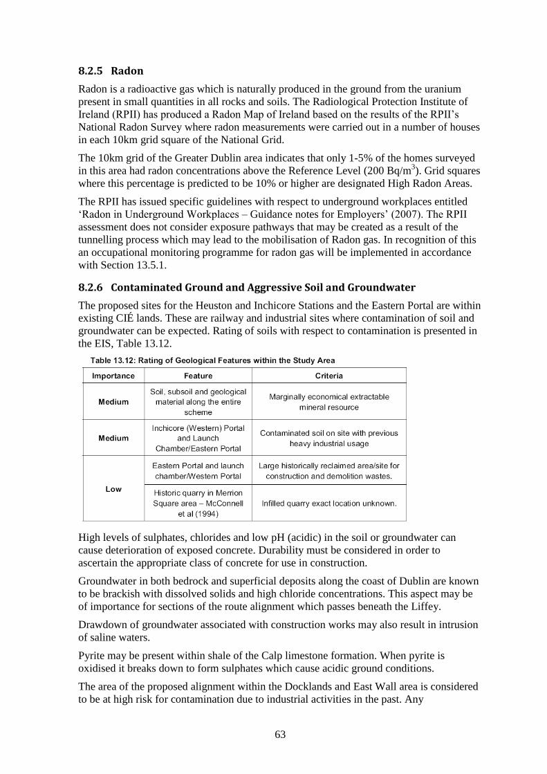
63
8.2.5 Radon
Radon is a radioactive gas which is naturally produced in the ground from the uranium
present in small quantities in all rocks and soils. The Radiological Protection Institute of
Ireland (RPII) has produced a Radon Map of Ireland based on the results of the RPII’s
National Radon Survey where radon measurements were carried out in a number of houses
in each 10km grid square of the National Grid.
The 10km grid of the Greater Dublin area indicates that only 1-5% of the homes surveyed
in this area had radon concentrations above the Reference Level (200 Bq/m3). Grid squares
where this percentage is predicted to be 10% or higher are designated High Radon Areas.
The RPII has issued specific guidelines with respect to underground workplaces entitled
‘Radon in Underground Workplaces – Guidance notes for Employers’ (2007). The RPII
assessment does not consider exposure pathways that may be created as a result of the
tunnelling process which may lead to the mobilisation of Radon gas. In recognition of this
an occupational monitoring programme for radon gas will be implemented in accordance
with Section 13.5.1.
8.2.6 Contaminated Ground and Aggressive Soil and Groundwater
The proposed sites for the Heuston and Inchicore Stations and the Eastern Portal are within
existing CIÉ lands. These are railway and industrial sites where contamination of soil and
groundwater can be expected. Rating of soils with respect to contamination is presented in
the EIS, Table 13.12.
High levels of sulphates, chlorides and low pH (acidic) in the soil or groundwater can
cause deterioration of exposed concrete. Durability must be considered in order to
ascertain the appropriate class of concrete for use in construction.
Groundwater in both bedrock and superficial deposits along the coast of Dublin are known
to be brackish with dissolved solids and high chloride concentrations. This aspect may be
of importance for sections of the route alignment which passes beneath the Liffey.
Drawdown of groundwater associated with construction works may also result in intrusion
of saline waters.
Pyrite may be present within shale of the Calp limestone formation. When pyrite is
oxidised it breaks down to form sulphates which cause acidic ground conditions.
The area of the proposed alignment within the Docklands and East Wall area is considered
to be at high risk for contamination due to industrial activities in the past. Any
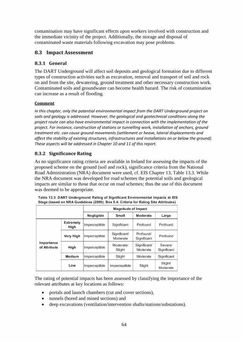
64
contamination may have significant effects upon workers involved with construction and
the immediate vicinity of the project. Additionally, the storage and disposal of
contaminated waste materials following excavation may pose problems.
8.3 Impact Assessment
8.3.1 General
The DART Underground will affect soil deposits and geological formation due to different
types of construction activities such as excavation, removal and transport of soil and rock
on and from the site, dewatering, ground treatment and other necessary construction work.
Contaminated soils and groundwater can become health hazard. The risk of contamination
can increase as a result of flooding.
Comment
In this chapter, only the potential environmental impact from the DART Underground project on soils and geology is addressed. However, the geological and geotechnical conditions along the project route can also have environmental impact in connection with the implementation of the project. For instance, construction of stations or tunnelling work, installation of anchors, ground treatment etc. can cause ground movements (settlement or heave, lateral displacements and affect the stability of existing structures, infrastructures and installations on or below the ground). These aspects will be addressed in Chapter 10 and 11 of this report.
8.3.2 Significance Rating
As no significance rating criteria are available in Ireland for assessing the impacts of the
proposed scheme on the ground (soil and rock), significance criteria from the National
Road Administration (NRA) document were used, cf. EIS Chapter 13, Table 13.3. While
the NRA document was developed for road schemes the potential soils and geological
impacts are similar to those that occur on road schemes; thus the use of this document
was deemed to be appropriate.
The rating of potential impacts has been assessed by classifying the importance of the
relevant attributes at key locations as follows:
portals and launch chambers (cut and cover sections),
tunnels (bored and mined sections) and
deep excavations (ventilation/intervention shafts/stations/substations).
65
The likely magnitude of any impact from the above features on the attributes was
then quantified. The rating of potential environmental impacts on the soils and geological
environment are based on the matrix presented in Table 13.3 which takes account of both
the importance of an attribute and the magnitude of the potential environmental impacts on
it. These impact ratings are also in accordance with impact assessment criteria provided in
the EPA publication ’Guidelines on the Information to be Contained in Environmental
Impact Statements’ (2002).
The construction impact will be monitored using environmental risk management
concepts. Comprehensive risk management is also aided by compliance with the Health
and Safety Authority (HSA) requirements for risk management of design and construction
works (for construction stage), and the appropriate standards and codes of practice for
site investigation works (including EN1997-2:2007 Annex B3 Ground Investigation
and Testing, and BS 5930 Code of Practice for Site Investigation Works).
All construction activities and works on site will be carried out according to best practice
guidelines, which are described in European and national standards as well as guidance
documents by professional organisations.
8.3.3 Construction Impact and General Mitigation Measures
In EIS, Chapter 13, construction phase impact and mitigation measures are assessed in
detail and summarised in Table 13.15. Impacts from construction of the DART
Underground and appropriate mitigation measures are discussed as follows.
General Construction
Fill will be used for construction of the Operational Control Centre, Maintenance facility
and ESB substation. Placement of fill will require the importation and deposition of fill or
reuse on site of fill material form within the site, leading to local changes in ground level
and topography.
An excess of soil and rock will result in the necessity for off-site disposal. Deposition of
fill may impact on properties of existing ground and affect groundwater flow.
Seepage may occur at slopes and excavations which can affect hydrogeological properties
of materials. In significant cuts this can lead to erosion and affect stability.
Mitigation Measures: in general, a minimum amount of soil and rock will be excavated.
Suitable surplus material will be used on site or other projects where possible.
Contaminated soils will be assessed, tested stored and managed according to the waste
hierarchy set out in the Landfill Directive (99/31/EC).
Seepage will be mitigated by employing a drainage system with suitable slope angles.
Excavation for diversion of utilities will be excavated using trenches minimizing the
amount of soil being generated.
Running Tunnels
Bored and mined soil and rock will be moved from tunnel to portals. During tunnel
construction there is potential of leakage or spillage of construction material such as raw
and uncured concrete, grout, fuel, lubricants and hydraulic fluids. Bitumen and sealants
used for water proofing of concrete surfaces can potentially impact on soils and
groundwater.
66
Mitigation Measures: excavated limestone must be shown to comply with regulations
regarding pyrites. Material shall be tested by the contractor to assure that material which
shall be used as structural backfill is suitable.
An occupational monitoring program for radon gas shall be implemented during
construction to avoid adverse impacts on humans.
A site investigation program has been carried out to inform contractor of appropriate TBM
and construction methodologies.
Portals and Launch Chambers, Deep Excavations
Cut and cover excavation of soil at both Inchicore and Docklands can encounter potentially
contaminated ground (hotspots).
Retaining structures will be installed in the ground in the form of secant pile walls and
diaphragm panel walls. Diaphragm walls are excavated using the slurry trench method
which requires bentonite suspension. Ground support will be required in the form of
ground anchors which need to be installed in the ground.
Ground treatment may be necessary in areas where excavation is carried out in the close
proximity of structures which are sensitive to settlement and/or lateral ground movement.
Also the placement of material on site, handling of potentially harmful liquids and other
chemical substances can have a negative environmental impact. Leakage and spillage of
materials and substances on site can potentially contaminate subsoil.
Construction of portals and launch chambers, of running tunnels and of deep excavations
can have impact on soils and rock on site.
Mitigation Measures: excavated soil and rock will be managed in accordance with the
waste hierarchy as set out in Chapter 21 of the EIS (Waste Management). Spoil removal
will require specialist disposal (cf. EIS Chapter 21; Waste Management). Excavation
techniques shall comply with statutory bodies regarding workers health and safety.
Temporary retaining wall systems shall be designed to mitigate risk of wall or slope
instability. Ground reinforcement systems such as rock bolts, ground anchors and sprayed
concrete lining shall be used in open excavations.
8.3.4 Operational Impact and General Mitigation Measures
The operational phase will have an overall neutral impact on soils and geology. However,
in case of leakage of the tunnel, stations or shafts, the groundwater level may be affected.
There is also a risk of soil and groundwater contamination from spillage of wastewater,
chemical material and hydrocarbons.
Mitigation Measures: if design measures are implemented and the DART Underground is
operated and maintained as outlined in the EIS, specific mitigation measures are not
required.
8.4 Comments and Recommendation – Soils and Geology
Chapter 13 of the EIS addresses one aspect environmental impacts, i.e. the effect of
construction and operation of the DART Underground on soils and rock. Impacts of soil
and rock conditions on the construction and associated risks are addressed only very
briefly in Chapter 13. The following recommendations are made:
67
1. The EIS provides a description of the general geological situation along the alignment. The information is sufficient for assessing environmental impacts of construction activities on soil and rock formations. However, impact of geotechnical and geological conditions on construction of the DART Underground is only addressed in the chapter on Settlement.
2. Information provided as evidence during the Oral Hearing indicates that soil and rock conditions can vary more rapidly over short distances than anticipated.
3. Presently available information on soil and rock is insufficient for Detailed Design and a significantly more detailed assessment of the geotechnical and geological conditions within the tunnel sections and at locations of deep excavations (shafts and stations) is needed.
4. Occurrence of faults, zones of weakness and weathering in rock needs to be determined more reliably, in particular in locations of deep excavations and mixed face tunnelling conditions. An important task is to establish the rockhead level and rockhead conditions along and perpendicular to the DART Underground alignment.
5. The extent of contaminated ground shall be determined by detailed investigations of all areas where excavations are proposed, these investigations shall be conducted prior to the commencement of excavation works as indicated by the applicant in ‘Brief of Evidence – Waste Management’ submitted to the Oral Hearing into the Railway Order application on the 17th day of December, 2010.
6. Potential obstructions and hazards including, inter alia, foundations, services, river walls and ordnances relating to the North Strand WWII bombing event shall be identified and addressed in the Detailed Design stage.
68
9 Hydrogeological Conditions
9.1 General
DART Underground involves the construction of two main types of permanent
underground structures below ground which can have an impact on the hydrogeology
along the project alignment, namely:
bored tunnels and mined tunnels (cross passages)
cut and cover structures (stations and shafts).
In addition, temporary and enabling works shall be carried out which could have negative
hydrogeological consequence. A potentially negative impact would be lowering of the
water table along the alignment generally or at the stations and shafts. This impact could be
either temporary or permanent in nature and would result from the abstraction of
significant quantities of groundwater from either the bored tunnels or the excavated
stations and shafts. However, the proposed construction methodology is aimed at
minimising the inflow of groundwater into the temporary excavations and the construction
of structures which are effectively water tight. This approach therefore reduces the amount
of dewatering required during construction, the need for significant permanent dewatering
and most importantly will minimise any negative hydrogeological impact.
9.2 Hydrogeology of Project Area
The topography and landscape is dominated by the presence of the Liffey which has
affected the most recent geomorphology of Dublin City and is a prevailing influence on
drainage along the proposed route. The Liffey is considered to be estuarine from
Islandbridge until it enters the Irish Sea via Dublin Bay. Along with the Liffey, there are a
number of surface water bodies along the proposed route including the river Camac and the
river Poddle. These water bodies are culverted in places, the Camac for instance is
culverted for much of its length including beneath Heuston Station to its outfall in to the
Liffey.
The hydrogeological regime and features of importance such as groundwater abstractions,
groundwater dependent ecosystems, archaeology and buildings are described in Chapter 14
of the EIS and were addressed in evidence presented at the Oral Hearing (OH-No. 28; K.
Cullen: Hydrogeology).
9.2.1 Groundwater
The EIS shows that there are two main sources of groundwater along the DART
Underground alignment:
shallow groundwater associated with fluvioglacial and Alluvial /estuarine granular
deposits; and
deeper groundwater associated with the Carboniferous Limestone bedrock.
The Dublin urban groundwater body is underlain by interbedded limestones and shales and
there are also some sandstones present. The bedrock aquifers tend to be dominated by
fissure or fracture flow with very little to no flow in the matrix. The limestone bedrock has
a low groundwater storage capacity in the order of 1 to 2 %.
69
The DART Underground lies in a regional groundwater discharge zone where the
groundwater bearing formations tend to discharge into either the surface waters, or where
this is not possible, into the Irish Sea. Groundwater flows in a general eastward direction
and contributes to the various rivers or discharges directly at the Irish Sea coast at Dublin
Bay. The direction of groundwater flow particularly in the overburden deposits is towards
the Liffey. There is a relatively shallow horizontal gradient in the water table
controlled essentially by the tidal channel of the Liffey with an upward vertical component
of flow reflecting the discharge zone.
9.2.2 Engineering Geology
No major bedrock fault structure is recognised as passing through the project area. The
limestone bedrock that underlies the DART Underground route is a locally important
aquifer. Limestone bedrock underlies the full length of the tunnel alignment.
The bedrock is covered by overburden consisting of inter-bedded glacial boulder clay and
fluvio-glacial silts, sands and gravels. The glacial deposits are in turn overlain in places by
post-glacial Alluvial /estuarine silts, sands and gravels. The natural overburden is
predominantly overlain by recent made ground.
The glacial boulder clay, which has generally a very low permeability in the order of 1-10
m/s or lower, is often embedded between other more permeable formations including the
limestone bedrock. The glacial boulder clay will also act as a confining layer where the
groundwater head in an underlying more permeable formation is above the base of the
boulder clay layer. Lenses/layers of sands and gravels found within the overburden have a
higher permeability than the boulder clay. The overlying glacial and post glacial deposits
have no aquifer classification though they are likely to be capable of supplying usable
supplies of groundwater.
Artesian and/or sub-artesian groundwater conditions have been encountered within the
glacial sands and gravels in some locations.
Engineering geology can provide important information regarding the stratification and
composition of different soil layers and rock formations. A complex interlayering of
glacial gravels and boulder clay deposits can be present within the project area. This
stratification of soil layers affects also groundwater conditions.
Permeable soil layers are likely to be in hydraulic continuity with the Liffey and therefore
have a significant recharge potential. Glaciomarine clays can be composed of a sequence
of coarsening upwards clays, silts and fine sands which are particularly difficult to control
under wet conditions. These deposits are restricted to the port area and can affect the
alignment between East wall, Docklands and Pearse station.
Presence of glacial sands and gravel horizons within the boulder clays could result in
gravity collapse and local instability, groundwater inundation and running sands. Such
layers are difficult to predict. Mixed face conditions are likely to encounter such soil
formations and could cause difficulties during underground excavation.
9.2.3 Hydrochemistry
The hydrochemistry of the groundwater along the route has been impacted by the
proximity of the tidal stretch of the Liffey and by the effects of urban drainage. The
combination of these impacts makes it difficult to provide any generalised signature of the
groundwater found along the route.
70
In general terms, the natural salinity of the groundwater in both the overburden and the
limestone bedrock, as described by the chloride values for example, increases to the east of
Islandbridge. This increase in salinity is to be expected as lower mineralised inland
groundwaters mix with brackish groundwaters associated with the estuarine section of the
Liffey. The background levels of chloride of around 50mg/l, which are elevated above a
more inland background of 20 to 30mg/l, increase eastwards along the south bank of the
Liffey with particularly high values recorded in the Docklands area. This picture is
reversed as the route heads away from the Liffey from Christchurch Station towards St.
Stephen’s Green station with the chloride values falling back to below 50mg/l again.
The salinity of the groundwater in the bedrock is generally higher than that recorded in the
overburden deposits. This suggests that a lens of fresher (i.e. lower salinity) groundwater
exists above the deeper bedrock saline groundwater possibly indicating that there is little
natural mixing of groundwaters along the alignment.
Groundwaters in this part of Dublin City are impacted by urban drainage as evidenced by
the high number of groundwater analyses that returned elevated levels of mineral oils and
hydrocarbons. A background concentration of 0.01mg/l for mineral oil in groundwater is
promoted by the Environmental Protection Agency. Many of the analyses returned levels
of mineral oils above 0.1 mg/l and in a few cases values greater than 1 mg/l were recorded.
Generally the trace elements are below accepted background levels for Irish groundwaters.
In some boreholes, however, the levels of barium, cadmium, nickel and arsenic levels
exceeded the EPA Guideline values for groundwater although no individual borehole had
elevated levels of all three elements. The elevated arsenic levels are concentrated in areas
previously used for industrial activities. Heavy metals, poly-aromatic hydrocarbons,
mineral oil contamination hand high levels of methane have previously been identified in
the Docklands area of the project. Elevated barium levels can be expected in the western
half of the route.
9.2.4 Site Investigation and Monitoring
Extensive site investigations in relation to hydrogeology were carried out which comprised
the following methods:
rotary holes
cable percussive holes
groundwater monitoring installations in bedrock
groundwater monitoring installations in both overburden and bedrock
falling head tests
packer tests
pump test.
Surface geophysic investigations were also undertaken along the route to provide
supplementary information on the rock head profile and the nature of the overburden
between the boreholes and in areas where intrusive investigations were not possible. In the
EIS is stated that the results of the geophysic investigations were calibrated against the site
investigation results where available. However, this assumption needs to be verified. Full
details of the types of geophysical investigations are outlined in Chapter 13, Section 13.2.
A programme of groundwater level monitoring continued for 1 year. In general and
consistent with the estuarine setting, the water table is shallow and within or close to the
base of the made ground deposits. The piezometric level of the groundwater within the
limestone bedrock is generally close to the water table level.
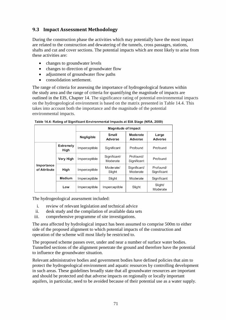
71
9.3 Impact Assessment Methodology
During the construction phase the activities which may potentially have the most impact
are related to the construction and dewatering of the tunnels, cross passages, stations,
shafts and cut and cover sections. The potential impacts which are most likely to arise from
these activities are:
changes to groundwater levels
changes to direction of groundwater flow
adjustment of groundwater flow paths
consolidation settlement.
The range of criteria for assessing the importance of hydrogeological features within
the study area and the range of criteria for quantifying the magnitude of impacts are
outlined in the EIS, Chapter 14. The significance rating of potential environmental impacts
on the hydrogeological environment is based on the matrix presented in Table 14.4. This
takes into account both the importance and the magnitude of the potential
environmental impacts.
The hydrogeological assessment included:
i. review of relevant legislation and technical advice
ii. desk study and the compilation of available data sets
iii. comprehensive programme of site investigations.
The area affected by hydrological impact has been assumed to comprise 500m to either
side of the proposed alignment to which potential impacts of the construction and
operation of the scheme will most likely be restricted to.
The proposed scheme passes over, under and near a number of surface water bodies.
Tunnelled sections of the alignment penetrate the ground and therefore have the potential
to influence the groundwater situation.
Relevant administrative bodies and government bodies have defined policies that aim to
protect the hydrogeological environment and aquatic resources by controlling development
in such areas. These guidelines broadly state that all groundwater resources are important
and should be protected and that adverse impacts on regionally or locally important
aquifers, in particular, need to be avoided because of their potential use as a water supply.
72
There is also justifiable concern in relation to the potential impact of groundwater
drawdown, ingress, settlement and pollution.
9.4 Impact Assessment
9.4.1 General Impact
The principle potential impact on the hydrogeological regime by DART Underground
would be the lowering of the water table (and/or piezometric surface) along the alignment
in general or at the main stations and shafts specifically. This potential impact could be
either temporary or permanent in nature and would result from the abstraction of
significant quantities of groundwater from the bored tunnels and/or the excavated stations
and shafts.
Temporary excavations below the water table usually involve some element of dewatering
to allow for dry working conditions. Also, continuous pumping of groundwater may be
required where permanent structures are not water tight. In these circumstances there may
be either temporary or permanent impacts or both on the water table depending on the
nature of the hydrogeological regime, the permeability of the geological formations present
and the depth, and size of structures.
The design rationale is that all permanent underground structures will be effectively water
tight at completion of construction. However, in order to assure that design specifications
are actually achieved, extensive field monitoring is required.
9.4.2 Running Tunnels
Minimising the dewatering requirement will be achieved in the first case with the use TBM
construction. The tunnels will be continually lined during the tunnelling process. If a large
amount of water is encountered in the ground, pressure at the tunnel faces can be
maintained above natural hydrostatic pressure of the ground through use of an EPBM,
which will minimise groundwater inflow. The continuous lining of the tunnels and
maintenance of high face pressure will prevent significant groundwater ingress into the
tunnel and any significant lowering of the water table during construction.
9.4.3 Stations and Shafts
Stations and shafts will be constructed using secant piles or diaphragm wall panels, which
– if properly constructed – are effectively water tight. These will be excavated down
through the overburden strata and seated in the bedrock, except at Inchicore Station.
The retaining walls will have the effect of ‘cutting off’ groundwater flow into the
excavations from the overburden deposits. The deepening and widening of the station and
shaft openings in bedrock will incorporate grouting of the advancing faces where necessary
and the preferential grouting of encountered significant water bearing bedrock fissures to
minimise groundwater inflows.
9.4.4 Enabling Works
Temporary excavations and draw-down of the groundwater by drainage to the excavation
and/or pumping can affect the groundwater situation.
73
9.5 Mitigation Measures
9.5.1 General Mitigation Measures
Where significant water bearing fractures are encountered, high pressure grouting will be
used to seal these up and prevent water ingress. This will prevent the draining of large
water bearing fractures and further minimise the impacts on the water environment. This
grouting process will also be used during the deepening and widening of stations and mine
shafts between tunnels.
Groundwater level monitoring will be undertaken according to the preliminary Water
Monitoring Plan which is part of the overall construction monitoring scheme. The
Contractor will be obliged to develop a detailed Water Monitoring Plan from the
preliminary Water Monitoring Plan. The Contractor will also compile a Groundwater
Action Plan which will state what actions they will take if monitoring shows that the
groundwater levels are moving outside their expected range. Each part of the plan will be
specific to each particular construction location, the works on-going at any given time and
the construction methods employed.
9.5.2 Construction of Tunnels and Cross Passages
The construction methodology proposed for DART Underground is founded on the
principle of minimising the inflow of groundwater into the temporary excavations and the
construction of structures which are effectively water tight. The continuous lining of the
tunnels and the ability to maintain high face pressures will prevent groundwater
ingress into the tunnel and so will prevent any significant lowering of the water table along
the line of the DART Underground route during construction and operation.
Cross passages will be constructed by the drill and blast method and supported by rock
anchors. Walls of cross passages will be supported and made water-tight by shotcrete.
Thus, cross passages shall become essentially watertight.
Provided that the design requirements are achieved, no permanent impact is expected
during construction and operation of the DART Underground.
9.5.3 Construction of Retaining Walls
Embedded retaining walls which –if properly constructed – are effectively water tight will
be installed at each station and shaft excavation and bored down to low permeability strata
or bedrock. Stations and shafts will extend into bedrock (limestone or shale) which
requires rock excavation by blasting. It is essential that walls penetrate sufficiently deep
into unfractured bedrock to limit inflow of groundwater.
Retaining walls will have the effect of cutting off groundwater flow into the excavation
from shallow permeable horizons such as the estuarine and glacial sand and gravel
deposits. Limiting the inflow into the tunnels and excavations from the bedrock will limit
the potential for any downward migration of groundwater from the overlying overburden
deposits and more importantly of surface waters, especially from the river Liffey.
9.5.4 Temporary Dewatering
Some temporary lowering of the water table and piezometric surface(s) is likely to
occur outside the excavations where temporary dewatering is required. The extent of any
such impact on groundwater levels outside the excavations will primarily depend on the
amount of groundwater abstracted from the excavations. Minimising the quantity of
74
groundwater pumped from the excavations will limit any potential lowering of
groundwater levels away from the construction sites.
9.5.5 Groundwater Abstractions
Potential impacts which may occur during the operational phase are:
reduction in inflows to the wells,
accidental spillage of potentially contaminating liquids.
Two groundwater abstractions have been identified within the project area:
Ushers Quay: a geothermal system consisting of an abstraction and discharge
well operated at the Local Government Management Building on Ushers Quay. Based on
the NRA significance criteria, this well would have a low importance.
There is a potential for the tunnelling and the dewatering at Island Street intervention shaft
to interfere with the groundwater wells associated with the geothermal system at the Local
Government Management Services Building.
Diageo: DCC records show abstraction from a bored well(s) on the St James’s Gate site.
However, Diageo have stated that this abstraction has not been active since early 2007. It is
possible that DART Underground would impact detrimentally on the Diageo well(s) if they
are used again in the future.
The magnitude of the tunnel construction on this system is classified as a ‘large
adverse’ potential impact as the base flow to the well could potentially be disrupted by the
tunnel construction.
In order to mitigate the potentially negative impact from construction of the DART
Underground, a monitoring regime is being I mplemented which will continue
during construction to confirm that there are no alterations to the baseline environment A
review of hydrogeological conditions of the geothermal system at the Local Government
Management Services building will be undertaken by the Contractor immediately before
commencement of construction to determine the operating characteristics of the system at
that time. A similar review of currently disused well at Diageo will also be undertaken by
the Contractor. This will provide a reference of the actual conditions pertaining
immediately before construction commences. In the event that the works associated with
DART Underground are detrimental to the existing active wells, replacement well(s) will
be drilled.
9.5.6 Hydrochemistry
The use of the TBMs and the construction methods planned for the various shafts indicate
that there will be a tendency for groundwater and fines to migrate to the construction area
rather than move to the wider area. In such circumstances any spillage within the
construction site will remain there until appropriate remedial action is taken to remove the
offending liquids and contaminated groundwater.
9.6 Site-specific Construction Impact and Mitigation
For each of the seven section of the DART Underground Scheme, the hydrogeological
conditions are described, as well as the predicted impact and proposed mitigation
measures. Due to the incorporated mitigation measures as outlined in the EIS,
groundwater inflows to tunnels and excavation will be minimised and consequently the
75
impact on groundwater levels will be reduced. Impact and possible mitigation measures
have been addressed in previous sections and to EIS Section 14.4.1.
9.6.1 Inchicore Cut and Cover, Inchicore Station and Inchicore Intervention Shaft
Conditions This area is composed of made ground and boulder clay with low permeability, with the
station being constructed primarily within the boulder clay deposits. There are no surface
water bodies currently running in this area. However, the Creosote Stream and its
tributaries were once located in this area. As part of the utilities survey, this stream was
identified on site where it is culverted. The stream had a history of contamination with
creosote.
Potential Impact Due to the ground conditions in this area, and the construction work to be undertaken,
the magnitude of the potential impact on the hydrogeological regime will be ’negligible’.
The predicted impact on the hydrogeological regime will also be ’negligible’. This
indicates that the significance of the impact will be ‘imperceptible’.
Mitigation Measures Mitigation measures incorporated in the design of the DART Underground Scheme will be
implemented. Monitoring shall be carried out to assure that specified limiting values are
not exceeded.
9.6.2 Inchicore to Heuston Station
Conditions The bored tunnels run mainly through bedrock. However these extend into gravel or
boulder clay in areas where the rock head is shallower. The Memorial Park
Ventilation/Intervention shaft extends through made ground, boulder clay, discrete gravel
lenses and finishes in the limestone bedrock. The Heuston station shafts extend through
made ground, glacial gravel and finish in the limestone bedrock. The Camac river is
culverted beneath Heuston station which limits its connection to the groundwater. The
Liffey is tidal in this area and the lower reaches of the Camac may be tidally influenced
too.
Potential Impact The magnitude of the potential impact in this area will be ‘moderate adverse’ and this
is particularly the case at Heuston where gravels are present above the limestone. The
magnitude of the predicted impact will be ‘small adverse’ and the significance of the
impact will be ‘slight’.
Mitigation Measures Mitigation measures incorporated in the design of the DART Underground Scheme will be
implemented. Monitoring shall be carried out to assure that specified limiting values are
not exceeded.
9.6.3 Heuston Station to Christchurch Station
Conditions The bored tunnels are located mainly in the bedrock. The Island Street Intervention shaft
extends through made ground, gravel deposits and terminates in the limestone bedrock.
76
There is a thin layer of boulder clay material present in places, however this is not
continuous.
Shafts at Cook Street and Christchurch extend through made ground, boulder clay, discrete
gravel lenses and terminate in the limestone bedrock.
Potential Impact Dewatering at the Island Street Intervention shaft and the Christchurch station shafts would
result in the lowering of groundwater levels in the immediate area of the excavations. The
magnitude of the potential impact in this area will be ‘moderate adverse’ and this
is particularly the case at Island Street where gravels are present above the limestone. The
magnitude of the predicted impact will be ‘small adverse’ and the significance of the
impact will be ‘slight’.
Mitigation Measures Mitigation measures incorporated in the design of the DART Underground Scheme will be
implemented. Monitoring shall be carried out to assure that specified limiting values are
not exceeded.
9.6.4 Christchurch Station to St. Stephen’s Green Station
Conditions The works in this area will extend through made ground and Dublin boulder clay (DBC)
and will finish in the limestone bedrock.
Potential Impact The magnitude of the potential impact in this area will be ‘small adverse’ due to
the presence of boulder clay above the limestone. The magnitude of the predicted impact
will be ‘negligible’ and the significance of the impact will be ‘imperceptible’.
Mitigation Measures Mitigation measures incorporated in the design of the DART Underground Scheme will be
implemented. Monitoring shall be carried out to assure that specified limiting values are
not exceeded.
9.6.5 St. Stephen’s Green Station to Pearse Station
Conditions The works in this area extend through made ground, Alluvial sand and gravel deposits,
boulder clay and finish in the limestone bedrock.
Potential Impact The magnitude of the potential impact in this area will be ‘small adverse’ due to
the presence of boulder clay above the limestone. The magnitude of the predicted impact
will be ‘negligible’ and the significance of the impact will be ‘imperceptible’.
Mitigation Measures Mitigation measures incorporated in the design of the DART Underground Scheme will be
implemented. Monitoring shall be carried out to assure that specified limiting values are
not exceeded.
77
9.6.6 Pearse Station to Docklands Station
Conditions The works in this area extend through made ground, gravel deposits and boulder clay
and finish close to the limestone bedrock surface.
Potential Impact Tunnelling along this section has the capacity to act as a drain as it is being constructed
below the water table.
Dewatering at the Docklands station would result in the lowering of groundwater levels in
the immediate area of the excavation.
The magnitude of the potential impact in this area will be ‘moderate adverse’ due to
the presence of gravel above the limestone at the Docklands. The magnitude of the
predicted impact will be ‘small adverse’ and the significance of the impact will be ‘slight’.
Mitigation Measures This area has been highlighted as one where recharge to ground may be
employed successfully as a mitigation measure if necessary but further investigation will
be needed to confirm this during the construction phase. Mitigation measures incorporated
in the design of the DART Underground Scheme will be implemented. Monitoring shall be
carried out to assure that specified limiting values are not exceeded.
9.6.7 Eastern Portal and Cut and Cover Section
Conditions The works in this area extend through made ground and finish in gravel deposits. The
alignment rises from a depth of approximately 16m below ground level at the Eastern
Portal to tie into the existing at grade tracks.
Potential Impact Dewatering at the Eastern Portal and the Docklands cut and cover section would result in
the lowering of groundwater levels in the immediate area of the excavation.
The magnitude of the potential impact in this area will be ‘moderate adverse’ due to
the presence of gravel above the limestone at the Docklands. The magnitude of the
predicted impact will be ’small adverse’ and the significance of the impact will be ’slight’.
Mitigation Measures This area has been highlighted as one where recharge to ground may be
employed successfully as a mitigation measure if necessary but further investigation will
be needed to confirm this during the construction phase. Mitigation measures incorporated
in the design of the DART Underground Scheme will be implemented. Monitoring shall be
carried out to assure that specified limiting values are not exceeded.
9.7 Operational Impact
This impact assessment has identified that DART Underground has the potential to alter
the existing groundwater conditions. However, the manner of its construction and proposed
operational method ensures that DART Underground will not result in any significant
residual impact on the existing groundwater regime. On-going groundwater level
monitoring will be undertaken. Where DART Underground is deemed to have a significant
78
effect on the established groundwater regime appropriate, long term mitigation measures
will be implemented such as the provision of replacement water wells.
Activities or features which may impact the hydrogeological regime and
hydrogeological features during the operational phase of the proposed scheme include:
presence of permanent embedded retaining walls in tunnel portals
station boxes and intervention shafts
presence of the bored tunnels
storage of potentially contaminated materials such as fuel
accidental spillage of contaminated material from drains or foul sewers.
On completion of the construction phase the groundwater levels will rebound to their pre-
construction levels as no permanent dewatering is associated with the operation of
DART Underground. The line of the tunnels will not act as a preferential groundwater flow
or drainage path and so there will be no permanent lowering of the water table along the
line of the route.
Structures located in the more permeable overburden deposits and the bedrock have
the potential to have a greater impact on groundwater flow patterns. However, the
potential impact on groundwater flow patterns even in these formations is considered to
be insignificant.
9.8 Comments and Recommendation - Hydrogeology
The assessment of hydrogeological impacts during the construction and operational phase
of the DART Underground Scheme has been thorough and is based on generally accepted
methods and concepts. During the Oral Hearing evidence was given which clarified some
of the aspects which were not addressed in sufficient detail by the Applicant (OH-No. 28;
K. Cullen: Hydrogeology). The information provided by the Applicant with regard to
identified risks and proposed mitigation measures is satisfactory. Also, the proposed
monitoring program is reassuring.
The Detailed Design stage, to be carried out in compliance with EN 1997 (Eurocode 7:
Geotechnical design), shall include, inter alia, the following:
1. A determination of permissible limits (threshold and limiting values) for permanent or temporary groundwater level drawdown
2. Identification of areas and depths of potential contamination of groundwater and soil deposits.
3. A high degree of quality control during deep excavations relating to water-tightness of walls/structures
4. Mitigation proposals to protect groundwater quality and the hydrogeological regime in the event of a flooding occurrence during the construction phase.
79
10 Geotechnical Conditions
10.1 General
The EIS addresses in Chapter 13 how soils and geology could be affected by the
construction and operation of the DART Underground. Chapter 16 of the EIS considers the
consequences of settlement and ground movement. However, the EIS does not address
extensively the impact of geotechnical conditions on the construction of the DART
Underground and its consequences for the receiving environment. This is unfortunate as
the Preliminary Design report (Phase 2 report by Mott McDonald) has dealt with these
geotechnical issue in a separate chapter of Volume 5 (Geotechnical 231922R6001/C), cf.
EIS Volume 4, Appendices to Chapter 2 – Part 5. However, as the Phase 2 report was
included as Appendix to the EIS, the required information was available, albeit not for the
entire route of the DART Underground alignment (as Inchicore area was not included).
In the present report the geological and soil conditions have been addressed in Chapter 8
and hydrogeological conditions in Chapter 9, respectively. This chapter (10) reviews how
geotechnical aspects affect construction of the DART Underground and their impacts on
the receiving environment.
Geotechnical Investigations
The phased ground investigation programme included the preparation of various
geotechnical reports. The geological and geotechnical investigations comprised:
Phase 1: Development of Alignment Options - Parsons Brinckerhoff (Ireland) Ltd.
(2003).
Phase 2: Preliminary Design – Mott MacDonald Pettit Ltd. (2008).
Phase 3: Reference Design – Geological desk study and ground investigations
including walkover survey of the entire route and adjacent areas, including
rock exposures in the Dublin area.
Phase 1 and 2 studied the conditions along the alignment at that stage of the project and did
not include the section from Heuston to Inchicore. The Phase 2 study by Mott McDonald
highlighted the following two issues:
Rockhead level derived from percussion drillings
Anomalous areas where the rockhead depressions were considerably deeper or
wider than previously predicted.
The Phase 2 report emphasised the need for additional, more detailed assessment to assist
in Detailed Design of the scheme.
During Phase 3 (Reference Design for the EIS), additional information was compiled from
relevant published or pre-existing information, feedback from consultations, relevant
organisations and affected third parties. Also, additional ground investigations were
undertaken between December 2008 and September 2009, comprising 167 boreholes,
ranging in depth from 10.6 to 47.1m bgl. This corresponds to an average spacing of 45 m
between boreholes. The ground investigations covered the entire route from the proposed
Inchicore Station to East Wall.
The following geotechnical field and laboratory tests were carried out during Phase 3 of
the project.
80
10.1.1 Field Tests
The following field testing methods were employed:
able Percussion boreholes including SPT at 1.5m depth intervals during drilling
Rotary core drill holes with recovery of disturbed and undisturbed soil samples and
of rock samples
Trial pits and recovery of bulk soil samples
Window samples
Groundwater monitoring and sampling
Variable head permeability tests
Packer permeability tests
Downhole geophysical surveying
Geophysical surveying
Surveying
Condition survey
Pumping tests.
10.1.2 Laboratory tests:
The following laboratory testing of overburden (soil) and rock samples was conducted:
Routine soil classification tests
Determination of soil strength and compressibility
Frequency and nature of fracturing within bedrock
Permeability of both the overburden (soil) and underlying bedrock
Samples tested under waste acceptance criteria for contaminants.
10.2 Geophysical Testing
Surface geophysic testing was carried out along the route to provide
supplementary information on the rockhead profile and the nature of the overburden
between boreholes and in areas where intrusive investigations were not possible. The
following methods were employed:
Seismic refraction to provide information on the bedrock profile
Multichannel Analysis of Surface Wave (MASW) to provide supplementary
information on the stiffness of the overburden (one-dimensional and two-
dimensional methods)
2D resistivity profiles (supplementary information on overburden and bedrock
profile).
Surface geophysical testing was carried out concurrently with intrusive investigations. The
factual information retrieved from the site investigation (such as rotary and cable
percussive borehole logs) was provided to the geophysicists to be used in the calibration of
the geophysical data acquired. However, it is difficult to verify to what extent this
information was actually used in the interpretation and calibration of seismic testing.
10.3 Ground Conditions
The EIS is based on a Reference Design, which requires the conservative assumption of
realistic geotechnical parameters. However, the EIS does not provide in the main report a
quantitative interpretation of geotechnical parameters, which is unfortunate. A general
81
geotechnical description is presented in tables of Appendix 13 (Soil laboratory data). It is
stated that for contractual reasons the contents of the interpretative geotechnical report
cannot be made available. However, in the Phase 2 report Volume 5: Geotechnical,
properties are summarised in two Tables 7.1 and 7.2. The information given on
geotechnical drawings of Phase 2 investigations emphasise the limited reliability of
identified soil layers:
“Stratigraphy of the superficial deposits should be used with caution as it is generally based on potentially unreliable third-party information at a considerable offset from the tunnel alignment.”
This statement must be taken into consideration when evaluating the EIS and the reliability
of conclusions made in the assessment of geotechnical impact.
Based on geotechnical, geological and geophysical information, inferred geological
sections were developed. The information obtained has been used to describe and evaluate
the likely impacts of construction work on the environment.
Baseline soils identified include boulder clays, sands and gravels, silts and sandy clays
from river deposits and made ground including rubble and waste materials. Bedrock
geology consists predominantly of limestones with shales.
Detailed baseline conditions are not presented in this report and only those aspects, which
are of significance for environmental impacts from geotechnical conditions, are discussed.
The general lithological/geological sequence of the overburden within the Dublin area
comprises the following units:
Fill and Made ground
Reclaimed land of soils with varying properties
Estuarine/Alluvial clays and silts
Estuarine/Alluvial gravels and sands
Fluvio-glacial deposits (glacial sands and gravels)
Glaciomarine clays and silts and sands
Glacial till – Dublin Boulder clay
Glacial gravels and sands
Bedrock (Carboniferous limestone)
Fill and Man-made Ground
Extensive areas of made ground are present along the route. The composition of made
ground varies widely and generally consists of a mixture of waste materials including, for
example, domestic refuse, clinker and demolition rubble. The thickness is generally
between 1m and 6m, but locally deeper. Thicknesses of made ground generally increase
towards the city centre and in the Docklands area.
Reclaimed Land
Fill materials in Dublin occur almost exclusively in the east of the City. The majority of fill
was uncontrolled in both manner of placement and material content. Fills are generally in
the range of 3 to 6 m thick. Hydraulic fill is mainly found in the port area, where fills are
anticipated to be loose to medium dense.
Alluvial Deposits
Alluvial clays and silts occur along the profiles of the various streams and rivers which
intersect the DART Underground route such as the rivers Camac, Poddle and Liffey. These
sediments show high lateral variability over short distances and tend to be inter-layered.
82
Some organic material was also noted within these sediments in isolated locations. Bands
of peat have been encountered locally within the Alluvial deposits in the area of the Liffey.
Estuarine Deposits
Estuarine deposits are present in the vicinity of the Liffey. The glacial sands and gravels
can contain cobbles and occasionally boulders. The glacial sands and gravels generally
occur as layers or lenses within the predominantly clayey glacial till. Estuarine clays and
silts prevail within the Liffey estuary particularly where the route crosses beneath the
Liffey at Sir John Rogerson’s Quay and emerges at North Wall Quay. These sediments are
soft to stiff clays and silts with some shell fragments and occasional interbedded sand
layers. However, in the area of the pre-glacial channel to the north of the Liffey (and also
to a lesser extent between the Liffey and St. Stephen’s Green) significant thicknesses are
present. The geology of the pre-glacial channel area is complex with glacial tills occurring
within glacial gravels and vice-versa and likely reflects the complexity of the variations
and different stages of ice sheet advance and withdrawal. Artesian and/or sub-
artesian groundwater conditions have been encountered within the glacial sands and
gravels in some locations.
Alluvium
Alluvial /estuarine sands and gravels dominate the area around Heuston Station, Diageo
Street, James’s Gate and Docklands. Soft silts and clays are likely to be present in the areas
along the Liffey, Tolka and other smaller streams and former river courses. Bands of peat
were encountered locally within Alluvial deposits in the vicinity of the Liffey. The selected
construction methods need to address the potential of ground instability and excessive
settlement associated with construction over and within these materials. The usually dense
to very dense sub-angular to sub-rounded sandy gravels and gravelly sands are locally
overlain by a thin layer of very recent soft estuary clays and silts.
Glacial Till (Dublin Boulder Clay)
The glacial till consists of a heterogeneous mixture of clay, silt, sand and gravel
with cobbles and boulders. It is locally known as Dublin brown or black boulder clay. The
till contains discrete, and in places extensive, layers, lenses and pockets of sand and gravel.
Dublin boulder clay is a stiff to very stiff glacial till found throughout the route. The till is
a well graded soil with numerous cobbles and boulders (the size of the boulders can
vary from 0.5 m to 3.0 m). The thickness of these deposits has been found to be very
variable across the area and up to 25m of till was noted in the area of the proposed tunnel
portal in Inchicore.
Glacial till is generally considered to be a good material for tunnel construction. However,
lenses and layers of sand and gravel are present within the predominantly clay matrix that
can contain groundwater under high pressure.
The presence of boulders within the glacial till has the potential to disrupt bored tunnelling
construction and also the construction of deep foundations. Previous experience indicates
that boulders with maximum dimensions greater than 0.5m are rarely encountered during
construction works in Dublin.
Glacial Gravels and Sands
Glacial gravels and sands can occur beneath, within and on top of the glacial till. Pockets,
lenses and layers of granular material, of varying extent, exist within the glacial till.
83
Glacial gravels within the boulder clay consist typically of very dense, angular to sub-
angular sandy, slightly silty gravels or very gravely, slightly silty sands.
Saturated gravels with sub-artesian pressures can be expected in some areas. Therefore,
engineering solutions will need to be capable of dealing with the potential risk of
encountering groundwater in localised areas within the till; inflows have the potential to be
sudden and variable, with the volume of inflow being dependent on the volume of granular
material, interconnectivity with other gravel deposits and groundwater pressure. The
presence of sandy or gravelly soils within cut slopes can potentially lead to
rapid dissipation of excavation induced negative pore water pressures and can lead to slope
instability. The presence of such materials can also have adverse effects on deep
foundation and shaft construction.
Glaciomarine Clays, Silts and Sands
Glaciomarine sediments are likely to be encountered in the areas around the Docklands.
They consist of very stiff (to hard) sandy, clayey silts and medium dense to dense silty
sands, locally interstratified with thin laminae of clay. Such deposits were presumably
buried below an advancing glacial ice sheet, leading to the very stiff to hard consistency
and slight overconsolidation of the material.
Bedrock
The bedrock encountered during the various phases of ground investigation defines an
undulating bedrock profile formed where changes in the ordnance level of the top of rock
can change relatively quickly over short distances. The bedrock profile has
been particularly influenced by recent geological history where stress relief and weathering
occurred. In Dublin city centre the bedrock consists of carboniferous limestone
interbedded with mudstone and shale (Calp limestone). Due to the nature of the study area
and the subsequent scarcity of bedrock exposures it is difficult to define all structural
manifestations but the resolution of minor fault gouge and recovery of fault breccia
suggests that these fault zones are singular restricted features rather than dominating over
extensive areas.
Weathered Rock Head
The occurrence of weathered rock head is variable across the route. Where encountered,
the engineering properties tend to be poorer and can potentially cause problems in
achieving an adequate cut-off for retaining walls. Design and construction solutions will
need to consider the impact on foundation construction and make provision to achieve an
adequate cut-off for retaining walls. These fractured zones are commonly limited to the
uppermost 0.5 to 3m of the underlying bedrock, but deposition of silty clay materials along
open fractures and joints can reach to considerable depths within the bedrock. Weathered
rock encountered during the site investigation was generally ≤ 0.5m.
Karst features are not likely to be encountered along the DART Underground route.
Groundwater
Groundwater conditions have been addressed in Chapter 9, Hydrogeology and are only
briefly mentioned here. The groundwater level is typically between 2m and 4m below
ground level in the city centre area but may be deeper where ground levels are more
elevated. Sub-artesian groundwater pressure and/or running sands and gravels have
been encountered in several areas, particularly associated with the pre-glacial
84
buried channel to the north of the Liffey. The hydrogeological aspects are discussed in
Chapter 10.
10.4 Extent of Ground Investigations
Phase 3 comprised 167 boreholes which correspond to an average spacing of 45m, or 90m
if the two tunnel routes are taken into consideration. In addition, results from previous
investigation phases and desk studies were available for preparation of the EIS. However,
the DART Underground includes large construction sites for stations, shafts and tunnel
portals for the design and execution of which detailed geological and geotechnical
information is needed.
The type of geotechnical investigation methods employed in the Phase 3 study is limited to
boring and SPT. Chapter 10 of the Phase 2 by report Mott McDonald proposed additional
ground investigation methods which could provide more detailed and reliable factual
information. These include:
Rotary open hole and core investigations
Cone penetration testing (CPT) and in very soft soils with pore water pressure
measurement (CPTU)
Laboratory testing
Piezometer installation
Down-hole geophysical logging and
Contamination screening.
It has not been possible to verify whether and to which extent the above proposed
investigations have been carried out. For instance, results from cone penetration tests have
not been found in the EIS factual information. In areas with difficult ground conditions
(especially in the eastern part of the DART Underground alignment), cone penetration
testing (CPT) or cone penetration testing with pore water pressure measurement (CPTU)
would have been more suitable than Standard Penetration Testing (SPT) to determine
quantitative properties of the stiffness and strength of soft and loose soils. It is in such
areas with soft deposits and variable fill where the greatest geotechnical hazards can be
expected.
10.5 Reliability of Geotechnical Properties
Factual information from various investigations has been compiled in the EIS, Volume 4,
Appendices 1 – 19. However, as no interpretation or comparison of test data from different
types of investigations is given in the EIS, it was difficult to assess the quality and
reliability of predicted and assumed soil and rock properties. Detailed information
regarding geotechnical properties of soil layers is of particular importance in the case of
deep excavations in the vicinity of sensitive structures.
The uncertainty regarding geotechnical properties of soil and rock is illustrated by the
following example. The geotechnical conditions at the planned station at St. Stephen’s
Green are shown in the below Figure 1 as plan and geological profile (between chainage
15+900 and 16+350). Eight boreholes (BH 42 – BH 49) were carried out as part of the
Phase 3 investigation. In addition, surface seismic investigations (seismic refraction and
MASW) were performed along and perpendicular to the alignment.
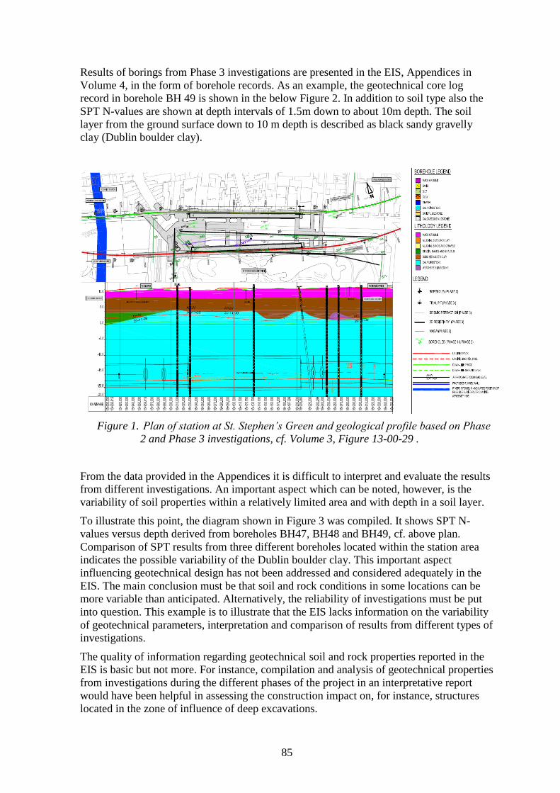
85
Results of borings from Phase 3 investigations are presented in the EIS, Appendices in
Volume 4, in the form of borehole records. As an example, the geotechnical core log
record in borehole BH 49 is shown in the below Figure 2. In addition to soil type also the
SPT N-values are shown at depth intervals of 1.5m down to about 10m depth. The soil
layer from the ground surface down to 10 m depth is described as black sandy gravelly
clay (Dublin boulder clay).
Figure 1. Plan of station at St. Stephen’s Green and geological profile based on Phase
2 and Phase 3 investigations, cf. Volume 3, Figure 13-00-29 .
From the data provided in the Appendices it is difficult to interpret and evaluate the results
from different investigations. An important aspect which can be noted, however, is the
variability of soil properties within a relatively limited area and with depth in a soil layer.
To illustrate this point, the diagram shown in Figure 3 was compiled. It shows SPT N-
values versus depth derived from boreholes BH47, BH48 and BH49, cf. above plan.
Comparison of SPT results from three different boreholes located within the station area
indicates the possible variability of the Dublin boulder clay. This important aspect
influencing geotechnical design has not been addressed and considered adequately in the
EIS. The main conclusion must be that soil and rock conditions in some locations can be
more variable than anticipated. Alternatively, the reliability of investigations must be put
into question. This example is to illustrate that the EIS lacks information on the variability
of geotechnical parameters, interpretation and comparison of results from different types of
investigations.
The quality of information regarding geotechnical soil and rock properties reported in the
EIS is basic but not more. For instance, compilation and analysis of geotechnical properties
from investigations during the different phases of the project in an interpretative report
would have been helpful in assessing the construction impact on, for instance, structures
located in the zone of influence of deep excavations.
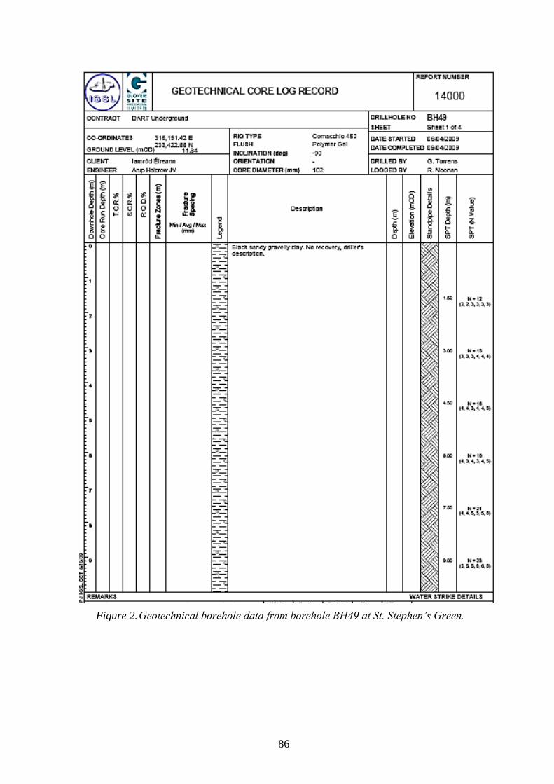
86
Figure 2. Geotechnical borehole data from borehole BH49 at St. Stephen’s Green.
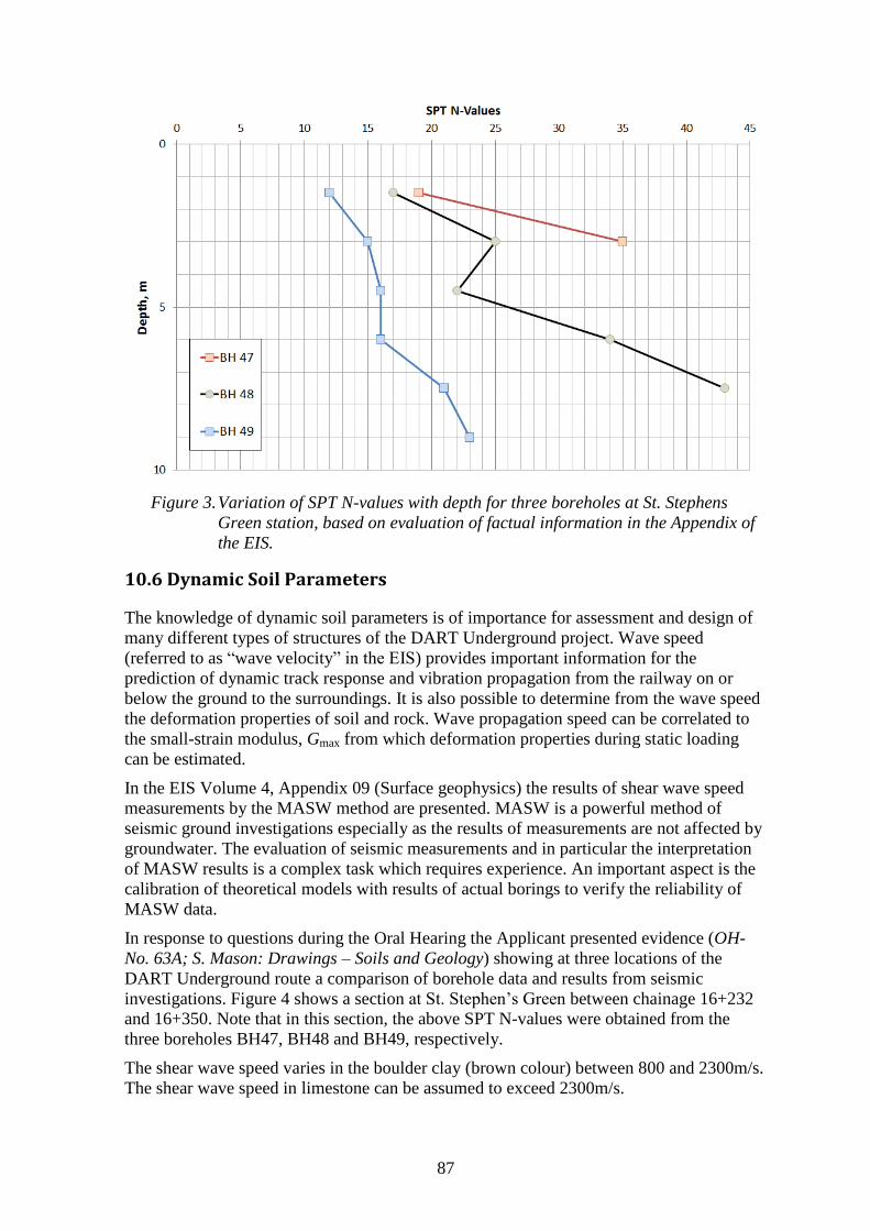
87
Figure 3. Variation of SPT N-values with depth for three boreholes at St. Stephens
Green station, based on evaluation of factual information in the Appendix of
the EIS.
10.6 Dynamic Soil Parameters
The knowledge of dynamic soil parameters is of importance for assessment and design of
many different types of structures of the DART Underground project. Wave speed
(referred to as “wave velocity” in the EIS) provides important information for the
prediction of dynamic track response and vibration propagation from the railway on or
below the ground to the surroundings. It is also possible to determine from the wave speed
the deformation properties of soil and rock. Wave propagation speed can be correlated to
the small-strain modulus, Gmax from which deformation properties during static loading
can be estimated.
In the EIS Volume 4, Appendix 09 (Surface geophysics) the results of shear wave speed
measurements by the MASW method are presented. MASW is a powerful method of
seismic ground investigations especially as the results of measurements are not affected by
groundwater. The evaluation of seismic measurements and in particular the interpretation
of MASW results is a complex task which requires experience. An important aspect is the
calibration of theoretical models with results of actual borings to verify the reliability of
MASW data.
In response to questions during the Oral Hearing the Applicant presented evidence (OH-
No. 63A; S. Mason: Drawings – Soils and Geology) showing at three locations of the
DART Underground route a comparison of borehole data and results from seismic
investigations. Figure 4 shows a section at St. Stephen’s Green between chainage 16+232
and 16+350. Note that in this section, the above SPT N-values were obtained from the
three boreholes BH47, BH48 and BH49, respectively.
The shear wave speed varies in the boulder clay (brown colour) between 800 and 2300m/s.
The shear wave speed in limestone can be assumed to exceed 2300m/s.
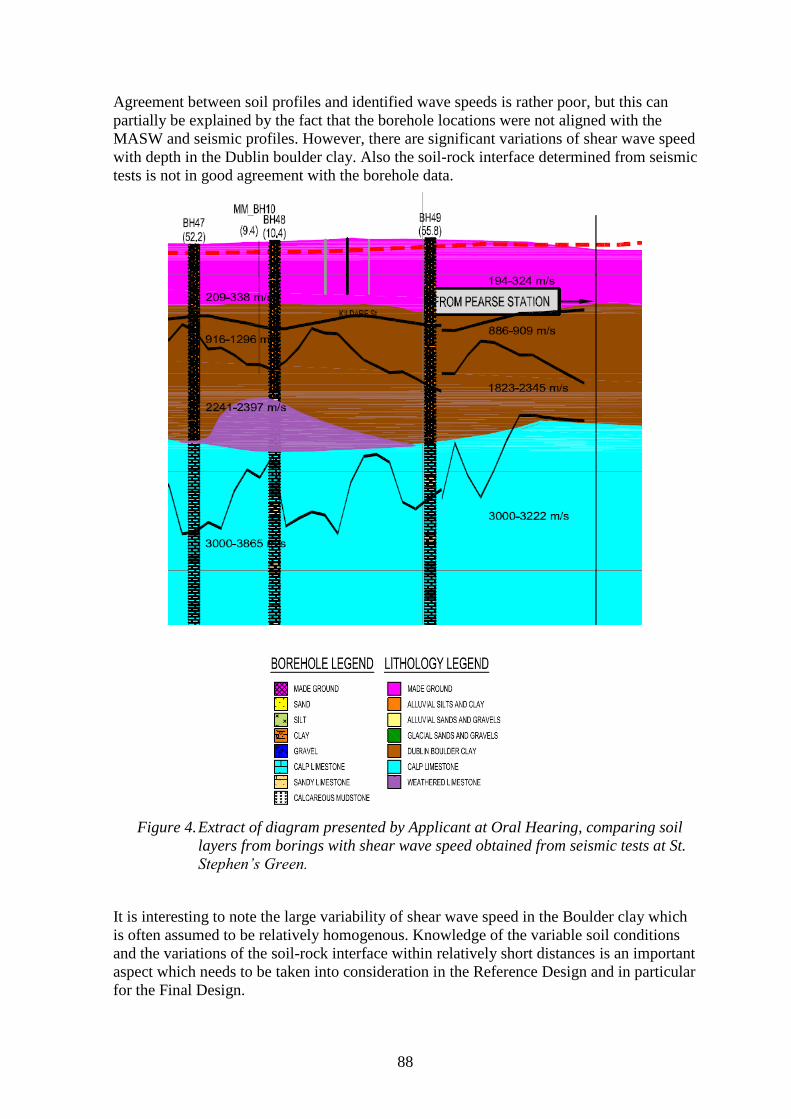
88
Agreement between soil profiles and identified wave speeds is rather poor, but this can
partially be explained by the fact that the borehole locations were not aligned with the
MASW and seismic profiles. However, there are significant variations of shear wave speed
with depth in the Dublin boulder clay. Also the soil-rock interface determined from seismic
tests is not in good agreement with the borehole data.
Figure 4. Extract of diagram presented by Applicant at Oral Hearing, comparing soil
layers from borings with shear wave speed obtained from seismic tests at St.
Stephen’s Green.
It is interesting to note the large variability of shear wave speed in the Boulder clay which
is often assumed to be relatively homogenous. Knowledge of the variable soil conditions
and the variations of the soil-rock interface within relatively short distances is an important
aspect which needs to be taken into consideration in the Reference Design and in particular
for the Final Design.
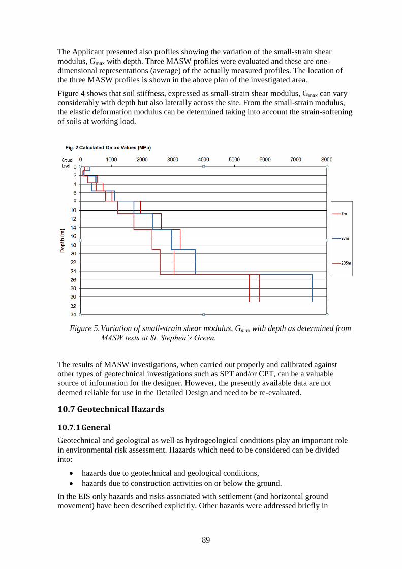
89
The Applicant presented also profiles showing the variation of the small-strain shear
modulus, Gmax with depth. Three MASW profiles were evaluated and these are one-
dimensional representations (average) of the actually measured profiles. The location of
the three MASW profiles is shown in the above plan of the investigated area.
Figure 4 shows that soil stiffness, expressed as small-strain shear modulus, Gmax can vary
considerably with depth but also laterally across the site. From the small-strain modulus,
the elastic deformation modulus can be determined taking into account the strain-softening
of soils at working load.
Figure 5. Variation of small-strain shear modulus, Gmax with depth as determined from
MASW tests at St. Stephen’s Green.
The results of MASW investigations, when carried out properly and calibrated against
other types of geotechnical investigations such as SPT and/or CPT, can be a valuable
source of information for the designer. However, the presently available data are not
deemed reliable for use in the Detailed Design and need to be re-evaluated.
10.7 Geotechnical Hazards
10.7.1 General
Geotechnical and geological as well as hydrogeological conditions play an important role
in environmental risk assessment. Hazards which need to be considered can be divided
into:
hazards due to geotechnical and geological conditions,
hazards due to construction activities on or below the ground.
In the EIS only hazards and risks associated with settlement (and horizontal ground
movement) have been described explicitly. Other hazards were addressed briefly in
90
chapters Chapter 3 (Scheme Description); 5 (Construction Strategy); 9 (Below Ground
Noise and Vibration); 13 (Soils and Geology) and 14 (Hydrogeology).
Management of environmental risks during construction and operation were addressed
during the Oral Hearing in extensive evidence given by the Applicant and in particular in
evidence OH-No. 22 and 22A¸ S. Fricker: Settlement and E-No-23, S. Fricker: Settlement
of permanent structures & utilities – Clarification for An Bord Pleanála.
10.7.2 Geotechnical and Geological Hazards
Although the ground conditions are generally favourable for the proposed DART
Underground Scheme, geotechnical hazards need to be considered with care during the
Detailed Design. The following geotechnical hazards, some of which have been identified
already during Phase 2 and reported in EIS (Volume 4, Appendices A2.5), were not
considered in sufficient detail in the EIS. Therefore, these need to be included in the
geotechnical risk assessment and management scheme:
variable and unexpected ground conditions (made ground and fill)
presence of soft, instable and compressive glacio-marine deposits
sand veins (interbedded as sandy laminations in boulder clay) causing dewatering
problems
gravel bed resulting in problematic groundwater inflows into excavation
contamination of ground and groundwater
high levels of methane
artesian or sub-artesian water pressure within glacial gravels
instability of shallow excavations in loose and soft ground (especially silty soils)
settlement of structures and installations in the ground (e.g. utilities) due to tunnel
construction
settlement of structures and installations in the ground due to permanent lowering
of groundwater
ground movements (vertical and horizontal) of structures due to construction of
deep excavations
instability of excavations in soil due to fissuring and/or shearing of glacial clays
instability of excavations in rock due to discontinuities, fissuring rock and
weathered rock
variability of rockhead level or unexpected deviations from design assumptions
bedded limestone with interbedded shale resulting in stability problems
dip of limestone bedding
voids in rock formation (potential of karstic features)
high groundwater pressure at tunnel level
running sands in boulder clay
difficulties during tunnel boring in mixed face conditions
settlement of loose, granular soil layers induced by blasting vibrations
obstructions to excavations (made ground, boulders etc.)
inflow of water into excavations due to granular horizons
unexpected ground conditions
unexploded ordnance within soft or loose superficial deposits
consequences of archeological excavations
contamination of groundwater.
91
Although this list of potential hazards due to geotechnical conditions is extensive, it may
not be complete. However, it can serve as a basis for establishing a comprehensive risk
management scheme. Some of the more important hazards are discussed briefly.
Lowering of Groundwater Table Dewatering of the ground and lowering the groundwater table may be required or caused
unintentionally by deep excavations or tunnel construction. This can induce consolidation
settlement in compressible clay or organic layers (occurring in Alluvial /estuarine deposits
and glacio-marine deposits) during construction but also extend into the operational phase.
Areas of concern are located along the Liffey estuary and in areas in proximity to buried
river channels.
High Groundwater Pressure Particularly adjacent to the Liffey the groundwater level is likely to be located close to the
ground surface. Significant heads of water (in excess of 10m) may impact upon a large
portion of the route. Confined water pressures may be present particularly within the
granular horizons of the glacial deposits, where sub-artesian water pressures have been
recorded.
Organic Matter in Fill Decay of organic matter present within fill material and reclaimed land in the east of the
alignment and within Alluvial deposits may result in potentially significant total and
differential settlements. Organic matter may also cause high concentrations of gas
(hydrogen sulphide, methane and carbon dioxide) during excavation, particularly within
confined spaces.
Near-surface Obstructions There is a potential for the presence of current and historical structures in the near
subsurface. Such structures could pose potentially significant problems for excavations
associated with cut-and-cover sections and station access structures.
Loose or Soft Deposits The presence of loose or soft soils within excavations may cause stability problems. As a
result of construction activities and resulting stress changes (pore water pressure and
effective stress), such soils may lose strength and stiffness (decompression). Under
unfavourable conditions, such soils could lead during tunnelling work to blow-
out/breakthrough to the ground surface where they overlie the tunnel.
Sand-filled Channels Encountering sand filled channels or other granular horizons within excavations or in
connection with tunnelling work may result in local instability, running sands or
groundwater inundation. This can lead to over-excavation and excessive face loss during
tunnelling work. Case histories from projects in the Dublin area of excavation within
glacio-marine clays and silts show a number of incidences of the material running into the
excavation or excessive ground movement.
10.7.3 Construction-related Hazards
In addition to geotechnical hazards due to ground conditions, also hazards related to
construction activities on and below the ground need to be taken into consideration. The
following list of problems, some of which were also addressed in different chapters of the
92
EIS and in Appendices (Volume 4 – Part 5: Case histories of the Mott McDonald report),
need to be considered:
Construction of water-tight wall elements due to construction deviations and or
obstructions
Seating of wall elements on blocks or fractured rock layers
Instability of excavations in rock due to unfavourable bedding planes
Leakage of groundwater in soil and fractured rock into deep excavations
TBM work in weathered rock and rock formations with potential faults
TBM work in mixed face conditions (soil-rock interface)
TBM work in deposits with layers and lenses of water-bearing sands
Wear on equipment (tunnelling and excavation) due to presence of abrasive ground
Obstructions in made ground encountered during wall construction (affecting
verticality of piles/panels and influencing water tightness)
Chiseling required to penetrate boulders and other obstructions
Draw-down of groundwater adjacent to excavation, due excessive pumping in
excavations (leakage through or below secant pile or diaphragm wall)
Difficulties with installation and/or retraction of ground anchors in hard rock
Implementation of ground treatment adjacent to tunnels and/or excavations
Potential hazards also exists in relation to the execution of foundation and ground
treatment work: installation and extraction of ground and rock anchors, compensation
grouting next to and below potentially affected structures, structural jacking of buildings or
building elements, curtain walling between tunnel and sensitive structures, underpinning of
existing, sensitive structures (historic buildings or monuments) etc.
10.7.4 Stability of Structures
One of the most important aspects of geotechnical design is to assure the stability of
structures, buildings or embankments during the construction and the operational phase.
The stability of structures with respect to geotechnical impacts can be endangered due to a
variety of effects such as:
Higher static loads than anticipated (vertical and horizontal stresses). An example
of such hazards is the unintended placement of fill material at the top of
excavations or slopes.
Excessive excavation depth, leading lower factor of safety.
Effects of dynamic loading on deep excavations for instance due to blasting.
Lower soil strength than anticipated or degradation of strength due to construction
activities (remoulding of soils).
Increased groundwater pressure due to, for instance infiltration of water from
leaking water mains, changes of water drainage or flooding.
Defects in construction execution, for instance construction methods and use of
materials with insufficient strength.
10.7.5 Settlement and Ground Movement
Ground movement, which comprises vertical settlement and lateral ground movement, can
be caused by one or a combination of different construction activities, such as:
Boring or excavation of trenches or walls in the ground
Excavation of soil and reduction of horizontal stress, leading to ground movement
adjacent to the excavation
93
Tunnelling work in soil and rock, resulting in ground loss and distortion of the
ground above and adjacent to the tunnel
Ground-water lowering caused by pumping or drainage, initiating consolidation
and creep settlement in soft, fine-grained soils (normally consolidated)
Heave at base of excavations in overconsolidated soils (boulder clay) due to stress
relief
Erosion of soil at slopes or unprotected excavations
Blasting-induced vibrations causing densification of granular soils (sand and
gravel).
Ground movement in the vertical and horizontal direction decreases usually with
increasing distance from the origin of disturbance. Also, ground movement is generally
smaller the lower the impact of disturbance (e.g. diameter of tunnel, depth of excavation,
amount of drained groundwater etc.).
More frequently, excessive ground movement and associated settlement in buildings or
structures below the ground is caused due to unforeseen geotechnical conditions and
inappropriate construction methods. The most efficient concept of minimising risks to
buildings due to ground movement is extensive control of the construction process and
monitoring of ground movements and of buildings. This concept is called the
“Observational Method” and described in detail in European standard EN 1997.
Potential settlement induced by the above mentioned construction activities can be
estimated using design recommendations as described in the geotechnical literature. The
assessment of settlement (and lateral ground movement) was carried out in the EIS
according to two widely accepted publications:
CIRIA C580 Report (2003). Embedded retaining walls – guidance for economic
design.
CIRIA Project Report 30 (1996). Prediction and effects of ground movements
caused by tunnelling in soft ground beneath urban areas.
The primary objective of the assessment of settlement of the ground and of structures on
and below the ground is to identify areas (and buildings) which are possibly affected by
construction of the DART Underground. Thus, settlement predictions are not intended -
nor suited - to predict actual building damage (cf. building damage classification). The
assessment methodology is clearly described in EIS Chapter 16.2.2. Important aspects of
this methodology are briefly summarized below as these have been discussed extensively
with the Observers during the Oral Hearing.
Assessment Methodology Phase 1: An empirical and conservative method is employed to estimate the magnitude and extent of unmitigated ground movements induced by tunnelling, tunnel approach structures, shaft construction and station excavations. The estimated ground movements are presented on settlement contour plans. Based on accepted criteria, any buildings, utilities or infrastructure potentially ‘at risk’ of damage are identified for either Phase 2 assessment or Phase 3 assessment.
Phase 2: For the buildings, utilities and infrastructure identified in Phase 1, the potential impact of the predicted ground movements is estimated in terms of the “damage category”. Depending on defined criteria, some buildings, utilities or infrastructure may require a Phase 3 assessment.
Phase 3: A Phase 3 assessment is undertaken on any buildings, utilities or infrastructure that, following either the Phase 1 or 2 assessment, are identified to potentially exceed acceptable levels of damage. Depending on the category of property, foundation configuration and architectural heritage category, some buildings and infrastructure will automatically be designated to undergo a Phase 3 assessment irrespective of the results of a Phase 2 assessment; all structures on the
94
Record of Protected Structures within the settlement zone defined by the 10mm contour will require a Phase 3 assessment, and buildings with piled or mixed foundations that lie within the overall zone of influence defined by the 1mm settlement contour, as identified during Phase 1, will automatically require a Phase 3 assessment.
Phase 3 comprises a detailed assessment in which the conservative assumptions made in the Phase 1 and 2 assessments are re-examined. The assessment is carried out prior to construction once the details of the construction and techniques and equipment to be used have been fully determined. The assessment comprises:
(i) A more detailed settlement assessment, more closely modelling the likely behaviour of the building, utility or infrastructure and the ground.
(ii) Internal and external inspections, surveys and reviews of as-built records to identify more precisely the areas and types of sensitivity and the general structural condition. If unacceptable damage is likely following the Phase 3 assessment then possible mitigation measures are designed and re-modelled in the assessment to bring the potential impact within the acceptable levels (i.e. a building damage category of slight for general buildings and very slight for buildings on the Record of Protected Structures– see Section 16.5.2). These mitigation measures are then implemented as part of the construction to safeguard the buildings, utility or infrastructure from exceeding its acceptable damage category and sustaining structural damage.
As the Phase 3 assessment is dependent on the knowledge of the actual construction techniques to be implemented, it is general practice that this assessment phase is carried out once a contractor has been appointed and hence the details of the construction methods are confirmed. However, consideration beyond Phase 2 has been given to be sure that practical measures can be designed and implemented to mitigate the effects of ground movement caused by construction.
In summary the Phase 3 assessment is used to review buildings, utilities and infrastructure identified by either the Phase 1 or 2 assessment and to finalise the use, where required, of mitigation measures which will bring these within the acceptable levels of impact prior to commencing construction.
Any cosmetic impacts, such as minor cracking that may occur within buildings associated with a damage category of slight for general buildings and very slight for buildings that are on the Record of Protected Structures, will be repaired under the Property Protection Scheme.
In response to questions during the Oral Hearing the Applicant provided evidence which
explains the different phases which are used to carry out settlement analyses, cf. below
Figure 6 (E- No. 23, S. Fricker: Settlement of permanent structures & utilities –
Clarification for An Bord Pleanála). With respect to the question why Phase 3 of the
settlement analysis was not included in Phase 3 (Reference Design) the Applicant quoted a
publication by Mair, Burland and Taylor (1996) “Prediction of ground movements and
assessment of risk of building damage due to bored tunnelling”:
“Detailed evaluation (Phase 3) is undertaken for those buildings classified in the second stage (phase) assessment as being at risk of category 3 damage (moderate) or greater……..The sequence and method of tunnelling should be given detailed consideration and full account taken of the three-dimensional aspects of tunnel layout……..…………”
Analysis of Ground Movement The EIS does not describe in sufficient detail how (vertical and horizontal) ground
movement was calculated, in particular due to installation of walls and subsequent
excavation. Ground movement (heave or settlement and horizontal displacement) can
occur due to the following reasons:
Construction of diaphragm wall panels or drilling of piles (installation-induced
ground movements)
Installation of ground anchors below adjacent structures
Excavation of soil inside retaining structure (station or shaft)
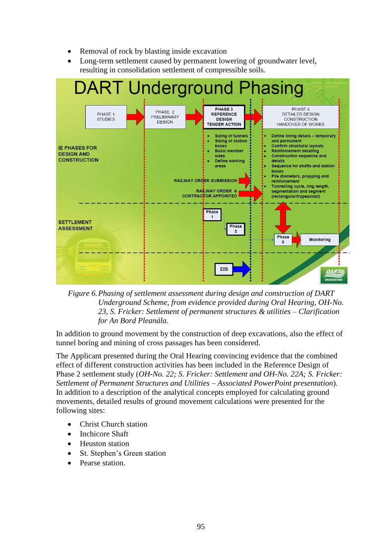
95
Removal of rock by blasting inside excavation
Long-term settlement caused by permanent lowering of groundwater level,
resulting in consolidation settlement of compressible soils.
Figure 6. Phasing of settlement assessment during design and construction of DART
Underground Scheme, from evidence provided during Oral Hearing, OH-No.
23, S. Fricker: Settlement of permanent structures & utilities – Clarification
for An Bord Pleanála.
In addition to ground movement by the construction of deep excavations, also the effect of
tunnel boring and mining of cross passages has been considered.
The Applicant presented during the Oral Hearing convincing evidence that the combined
effect of different construction activities has been included in the Reference Design of
Phase 2 settlement study (OH-No. 22; S. Fricker: Settlement and OH-No. 22A; S. Fricker:
Settlement of Permanent Structures and Utilities – Associated PowerPoint presentation).
In addition to a description of the analytical concepts employed for calculating ground
movements, detailed results of ground movement calculations were presented for the
following sites:
Christ Church station
Inchicore Shaft
Heuston station
St. Stephen’s Green station
Pearse station.
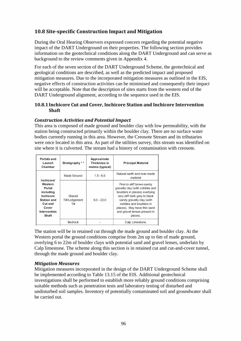
96
10.8 Site-specific Construction Impact and Mitigation
During the Oral Hearing Observers expressed concern regarding the potential negative
impact of the DART Underground on their properties. The following section provides
information on the geotechnical conditions along the DART Underground and can serve as
background to the review comments given in Appendix 4.
For each of the seven section of the DART Underground Scheme, the geotechnical and
geological conditions are described, as well as the predicted impact and proposed
mitigation measures. Due to the incorporated mitigation measures as outlined in the EIS,
negative effects of construction activities can be minimised and consequently their impact
will be acceptable. Note that the description of sites starts from the western end of the
DART Underground alignment, according to the sequence used in the EIS.
10.8.1 Inchicore Cut and Cover, Inchicore Station and Inchicore Intervention Shaft
Construction Activities and Potential Impact This area is composed of made ground and boulder clay with low permeability, with the
station being constructed primarily within the boulder clay. There are no surface water
bodies currently running in this area. However, the Creosote Stream and its tributaries
were once located in this area. As part of the utilities survey, this stream was identified on
site where it is culverted. The stream had a history of contamination with creosote.
The station will be in retained cut through the made ground and boulder clay. At the
Western portal the ground conditions comprise from 2m up to 6m of made ground,
overlying 6 to 22m of boulder clays with potential sand and gravel lenses, underlain by
Calp limestone. The scheme along this section is in retained cut and cut-and-cover tunnel,
through the made ground and boulder clay.
Mitigation Measures Mitigation measures incorporated in the design of the DART Underground Scheme shall
be implemented according to Table 13.15 of the EIS. Additional geotechnical
investigations shall be performed to establish more reliably ground conditions comprising
suitable methods such as penetration tests and laboratory testing of disturbed and
undisturbed soil samples. Inventory of potentially contaminated soil and groundwater shall
be carried out.
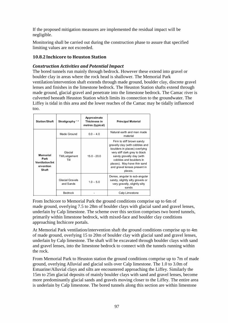
97
If the proposed mitigation measures are implemented the residual impact will be
negligible.
Monitoring shall be carried out during the construction phase to assure that specified
limiting values are not exceeded.
10.8.2 Inchicore to Heuston Station
Construction Activities and Potential Impact The bored tunnels run mainly through bedrock. However these extend into gravel or
boulder clay in areas where the rock head is shallower. The Memorial Park
ventilation/intervention shaft extends through made ground, boulder clay, discrete gravel
lenses and finishes in the limestone bedrock. The Heuston Station shafts extend through
made ground, glacial gravel and penetrate into the limestone bedrock. The Camac river is
culverted beneath Heuston Station which limits its connection to the groundwater. The
Liffey is tidal in this area and the lower reaches of the Camac may be tidally influenced
too.
From Inchicore to Memorial Park the ground conditions comprise up to 6m of
made ground, overlying 7.5 to 28m of boulder clays with glacial sand and gravel lenses,
underlain by Calp limestone. The scheme over this section comprises two bored tunnels,
primarily within limestone bedrock, with mixed-face and boulder clay conditions
approaching Inchicore portals.
At Memorial Park ventilation/intervention shaft the ground conditions comprise up to 4m
of made ground, overlying 15 to 20m of boulder clay with glacial sand and gravel lenses,
underlain by Calp limestone. The shaft will be excavated through boulder clays with sand
and gravel lenses, into the limestone bedrock to connect with the tunnels running within
the rock.
From Memorial Park to Heuston station the ground conditions comprise up to 7m of made
ground, overlying Alluvial and glacial soils over Calp limestone. The 1.0 to 3.0m of
Estuarine/Alluvial clays and silts are encountered approaching the Liffey. Similarly the
15m to 25m glacial deposits of mainly boulder clays with sand and gravel lenses, become
more predominantly glacial sands and gravels moving closer to the Liffey. The entire area
is underlain by Calp limestone. The bored tunnels along this section are within limestone
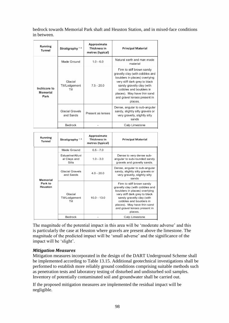
98
bedrock towards Memorial Park shaft and Heuston Station, and in mixed-face conditions
in between.
The magnitude of the potential impact in this area will be ‘moderate adverse’ and this
is particularly the case at Heuston where gravels are present above the limestone. The
magnitude of the predicted impact will be ‘small adverse’ and the significance of the
impact will be ‘slight’.
Mitigation Measures Mitigation measures incorporated in the design of the DART Underground Scheme shall
be implemented according to Table 13.15. Additional geotechnical investigations shall be
performed to establish more reliably ground conditions comprising suitable methods such
as penetration tests and laboratory testing of disturbed and undisturbed soil samples.
Inventory of potentially contaminated soil and groundwater shall be carried out.
If the proposed mitigation measures are implemented the residual impact will be
negligible.
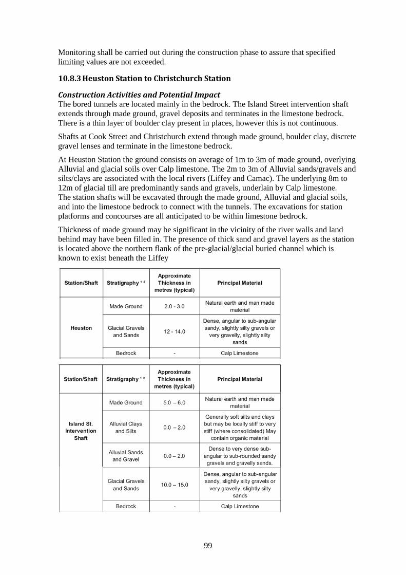
99
Monitoring shall be carried out during the construction phase to assure that specified
limiting values are not exceeded.
10.8.3 Heuston Station to Christchurch Station
Construction Activities and Potential Impact The bored tunnels are located mainly in the bedrock. The Island Street intervention shaft
extends through made ground, gravel deposits and terminates in the limestone bedrock.
There is a thin layer of boulder clay present in places, however this is not continuous.
Shafts at Cook Street and Christchurch extend through made ground, boulder clay, discrete
gravel lenses and terminate in the limestone bedrock.
At Heuston Station the ground consists on average of 1m to 3m of made ground, overlying
Alluvial and glacial soils over Calp limestone. The 2m to 3m of Alluvial sands/gravels and
silts/clays are associated with the local rivers (Liffey and Camac). The underlying 8m to
12m of glacial till are predominantly sands and gravels, underlain by Calp limestone.
The station shafts will be excavated through the made ground, Alluvial and glacial soils,
and into the limestone bedrock to connect with the tunnels. The excavations for station
platforms and concourses are all anticipated to be within limestone bedrock.
Thickness of made ground may be significant in the vicinity of the river walls and land
behind may have been filled in. The presence of thick sand and gravel layers as the station
is located above the northern flank of the pre-glacial/glacial buried channel which is
known to exist beneath the Liffey
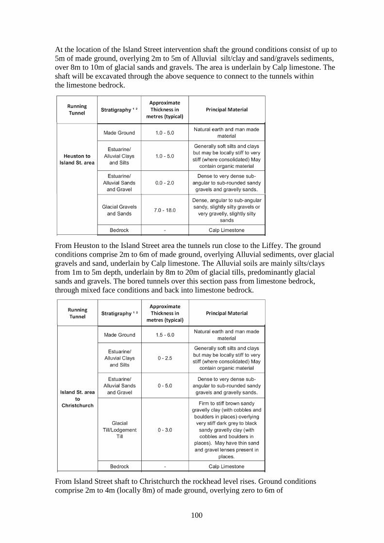
100
At the location of the Island Street intervention shaft the ground conditions consist of up to
5m of made ground, overlying 2m to 5m of Alluvial silt/clay and sand/gravels sediments,
over 8m to 10m of glacial sands and gravels. The area is underlain by Calp limestone. The
shaft will be excavated through the above sequence to connect to the tunnels within
the limestone bedrock.
From Heuston to the Island Street area the tunnels run close to the Liffey. The ground
conditions comprise 2m to 6m of made ground, overlying Alluvial sediments, over glacial
gravels and sand, underlain by Calp limestone. The Alluvial soils are mainly silts/clays
from 1m to 5m depth, underlain by 8m to 20m of glacial tills, predominantly glacial
sands and gravels. The bored tunnels over this section pass from limestone bedrock,
through mixed face conditions and back into limestone bedrock.
From Island Street shaft to Christchurch the rockhead level rises. Ground conditions
comprise 2m to 4m (locally 8m) of made ground, overlying zero to 6m of
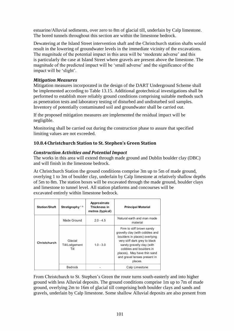
101
estuarine/Alluvial sediments, over zero to 8m of glacial till, underlain by Calp limestone.
The bored tunnels throughout this section are within the limestone bedrock.
Dewatering at the Island Street intervention shaft and the Christchurch station shafts would
result in the lowering of groundwater levels in the immediate vicinity of the excavations.
The magnitude of the potential impact in this area will be ‘moderate adverse’ and this
is particularly the case at Island Street where gravels are present above the limestone. The
magnitude of the predicted impact will be ‘small adverse’ and the significance of the
impact will be ‘slight’.
Mitigation Measures Mitigation measures incorporated in the design of the DART Underground Scheme shall
be implemented according to Table 13.15. Additional geotechnical investigations shall be
performed to establish more reliably ground conditions comprising suitable methods such
as penetration tests and laboratory testing of disturbed and undisturbed soil samples.
Inventory of potentially contaminated soil and groundwater shall be carried out.
If the proposed mitigation measures are implemented the residual impact will be
negligible.
Monitoring shall be carried out during the construction phase to assure that specified
limiting values are not exceeded.
10.8.4 Christchurch Station to St. Stephen’s Green Station
Construction Activities and Potential Impact The works in this area will extend through made ground and Dublin boulder clay (DBC)
and will finish in the limestone bedrock.
At Christchurch Station the ground conditions comprise 3m up to 5m of made ground,
overlying 1 to 3m of boulder clay, underlain by Calp limestone at relatively shallow depths
of 5m to 8m. The station boxes will be excavated through the made ground, boulder clays
and limestone to tunnel level. All station platforms and concourses will be
excavated entirely within limestone bedrock.
From Christchurch to St. Stephen’s Green the route turns south-easterly and into higher
ground with less Alluvial deposits. The ground conditions comprise 1m up to 7m of made
ground, overlying 2m to 16m of glacial till comprising both boulder clays and sands and
gravels, underlain by Calp limestone. Some shallow Alluvial deposits are also present from
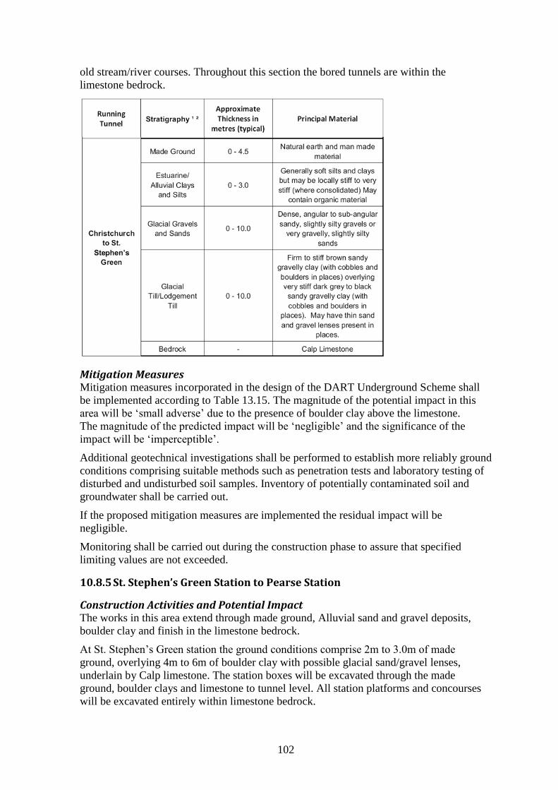
102
old stream/river courses. Throughout this section the bored tunnels are within the
limestone bedrock.
Mitigation Measures Mitigation measures incorporated in the design of the DART Underground Scheme shall
be implemented according to Table 13.15. The magnitude of the potential impact in this
area will be ‘small adverse’ due to the presence of boulder clay above the limestone.
The magnitude of the predicted impact will be ‘negligible’ and the significance of the
impact will be ‘imperceptible’.
Additional geotechnical investigations shall be performed to establish more reliably ground
conditions comprising suitable methods such as penetration tests and laboratory testing of
disturbed and undisturbed soil samples. Inventory of potentially contaminated soil and
groundwater shall be carried out.
If the proposed mitigation measures are implemented the residual impact will be
negligible.
Monitoring shall be carried out during the construction phase to assure that specified
limiting values are not exceeded.
10.8.5 St. Stephen’s Green Station to Pearse Station
Construction Activities and Potential Impact The works in this area extend through made ground, Alluvial sand and gravel deposits,
boulder clay and finish in the limestone bedrock.
At St. Stephen’s Green station the ground conditions comprise 2m to 3.0m of made
ground, overlying 4m to 6m of boulder clay with possible glacial sand/gravel lenses,
underlain by Calp limestone. The station boxes will be excavated through the made
ground, boulder clays and limestone to tunnel level. All station platforms and concourses
will be excavated entirely within limestone bedrock.
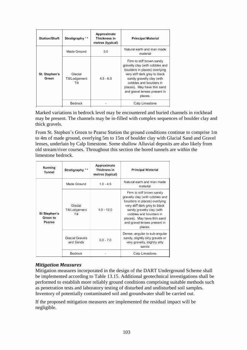
103
Marked variations in bedrock level may be encountered and buried channels in rockhead
may be present. The channels may be in-filled with complex sequences of boulder clay and
thick gravels.
From St. Stephen’s Green to Pearse Station the ground conditions continue to comprise 1m
to 4m of made ground, overlying 5m to 15m of boulder clay with Glacial Sand and Gravel
lenses, underlain by Calp limestone. Some shallow Alluvial deposits are also likely from
old stream/river courses. Throughout this section the bored tunnels are within the
limestone bedrock.
Mitigation Measures Mitigation measures incorporated in the design of the DART Underground Scheme shall
be implemented according to Table 13.15. Additional geotechnical investigations shall be
performed to establish more reliably ground conditions comprising suitable methods such
as penetration tests and laboratory testing of disturbed and undisturbed soil samples.
Inventory of potentially contaminated soil and groundwater shall be carried out.
If the proposed mitigation measures are implemented the residual impact will be
negligible.
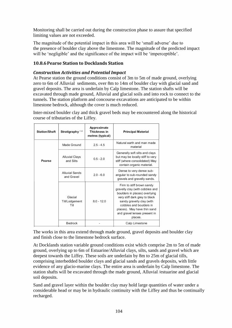
104
Monitoring shall be carried out during the construction phase to assure that specified
limiting values are not exceeded.
The magnitude of the potential impact in this area will be ‘small adverse’ due to
the presence of boulder clay above the limestone. The magnitude of the predicted impact
will be ‘negligible’ and the significance of the impact will be ‘imperceptible’.
10.8.6 Pearse Station to Docklands Station
Construction Activities and Potential Impact At Pearse station the ground conditions consist of 3m to 5m of made ground, overlying
zero to 6m of Alluvial sediments, over 8m to 14m of boulder clay with glacial sand and
gravel deposits. The area is underlain by Calp limestone. The station shafts will be
excavated through made ground, Alluvial and glacial soils and into rock to connect to the
tunnels. The station platform and concourse excavations are anticipated to be within
limestone bedrock, although the cover is much reduced.
Inter-mixed boulder clay and thick gravel beds may be encountered along the historical
course of tributaries of the Liffey.
The works in this area extend through made ground, gravel deposits and boulder clay
and finish close to the limestone bedrock surface.
At Docklands station variable ground conditions exist which comprise 2m to 5m of made
ground, overlying up to 6m of Estuarine/Alluvial clays, silts, sands and gravel which are
deepest towards the Liffey. These soils are underlain by 8m to 25m of glacial tills,
comprising interbedded boulder clays and glacial sands and gravels deposits, with little
evidence of any glacio-marine clays. The entire area is underlain by Calp limestone. The
station shafts will be excavated through the made ground, Alluvial /estuarine and glacial
soil deposits.
Sand and gravel layer within the boulder clay may hold large quantities of water under a
considerable head or may be in hydraulic continuity with the Liffey and thus be continually
recharged.
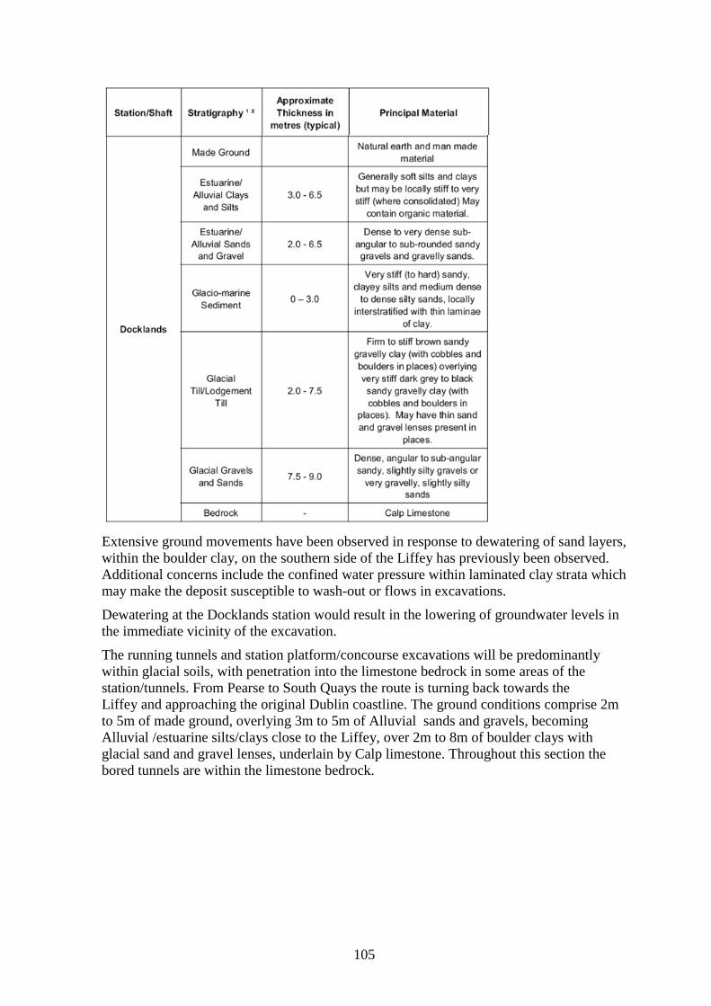
105
Extensive ground movements have been observed in response to dewatering of sand layers,
within the boulder clay, on the southern side of the Liffey has previously been observed.
Additional concerns include the confined water pressure within laminated clay strata which
may make the deposit susceptible to wash-out or flows in excavations.
Dewatering at the Docklands station would result in the lowering of groundwater levels in
the immediate vicinity of the excavation.
The running tunnels and station platform/concourse excavations will be predominantly
within glacial soils, with penetration into the limestone bedrock in some areas of the
station/tunnels. From Pearse to South Quays the route is turning back towards the
Liffey and approaching the original Dublin coastline. The ground conditions comprise 2m
to 5m of made ground, overlying 3m to 5m of Alluvial sands and gravels, becoming
Alluvial /estuarine silts/clays close to the Liffey, over 2m to 8m of boulder clays with
glacial sand and gravel lenses, underlain by Calp limestone. Throughout this section the
bored tunnels are within the limestone bedrock.
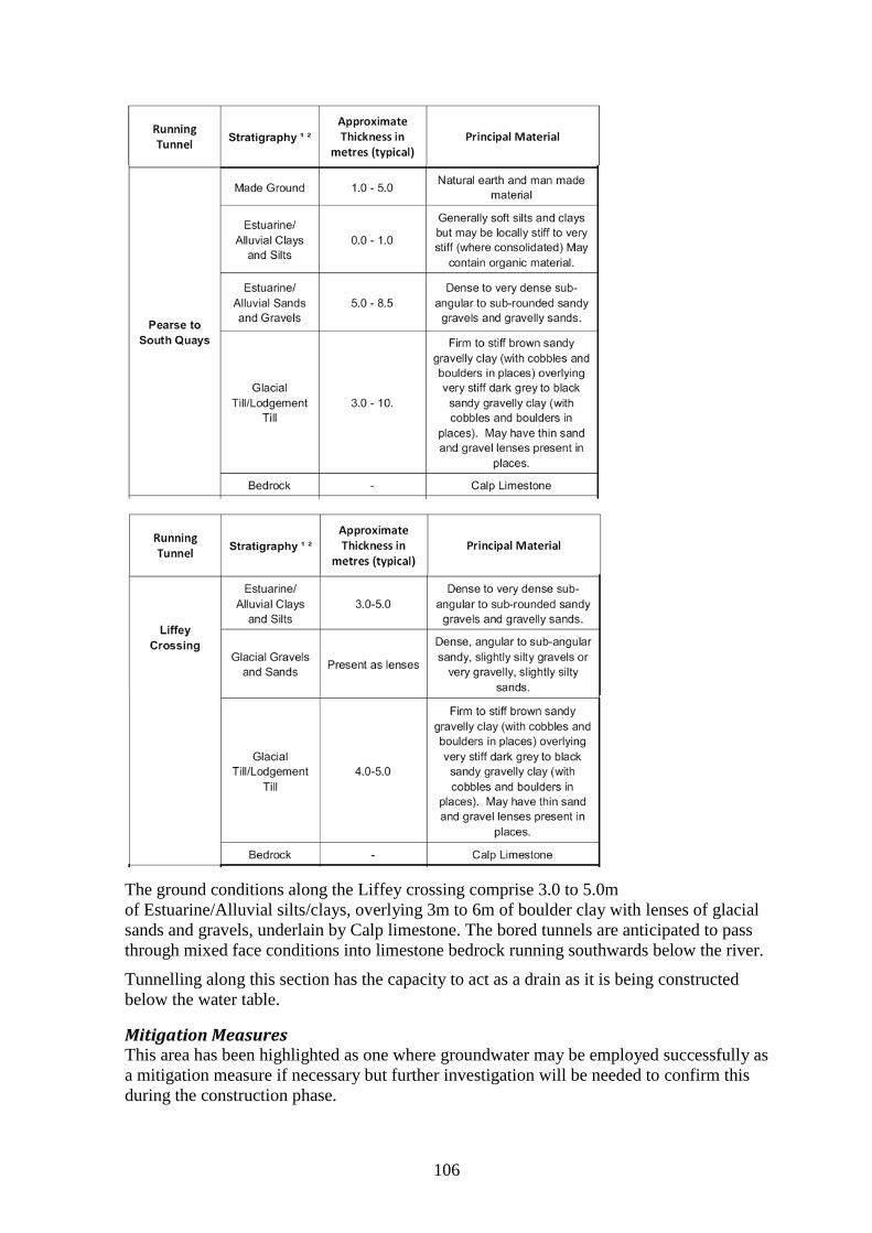
106
The ground conditions along the Liffey crossing comprise 3.0 to 5.0m
of Estuarine/Alluvial silts/clays, overlying 3m to 6m of boulder clay with lenses of glacial
sands and gravels, underlain by Calp limestone. The bored tunnels are anticipated to pass
through mixed face conditions into limestone bedrock running southwards below the river.
Tunnelling along this section has the capacity to act as a drain as it is being constructed
below the water table.
Mitigation Measures This area has been highlighted as one where groundwater may be employed successfully as
a mitigation measure if necessary but further investigation will be needed to confirm this
during the construction phase.
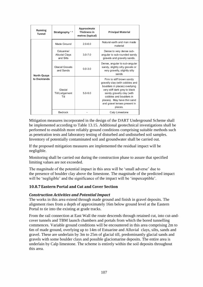
107
Mitigation measures incorporated in the design of the DART Underground Scheme shall
be implemented according to Table 13.15. Additional geotechnical investigations shall be
performed to establish more reliably ground conditions comprising suitable methods such
as penetration tests and laboratory testing of disturbed and undisturbed soil samples.
Inventory of potentially contaminated soil and groundwater shall be carried out.
If the proposed mitigation measures are implemented the residual impact will be
negligible.
Monitoring shall be carried out during the construction phase to assure that specified
limiting values are not exceeded.
The magnitude of the potential impact in this area will be ‘small adverse’ due to
the presence of boulder clay above the limestone. The magnitude of the predicted impact
will be ‘negligible’ and the significance of the impact will be ‘imperceptible’.
10.8.7 Eastern Portal and Cut and Cover Section
Construction Activities and Potential Impact The works in this area extend through made ground and finish in gravel deposits. The
alignment rises from a depth of approximately 16m below ground level at the Eastern
Portal to tie into the existing at grade tracks.
From the rail connection at East Wall the route descends through retained cut, into cut-and-
cover tunnels and TBM launch chambers and portals from which the bored tunnelling
commences. Variable ground conditions will be encountered in this area comprising 2m to
6m of made ground, overlying up to 14m of Estuarine and Alluvial clays, silts, sands and
gravel. These are underlain by 3m to 25m of glacial till, predominantly glacial sands and
gravels with some boulder clays and possible glaciomarine deposits. The entire area is
underlain by Calp limestone. The scheme is entirely within the soil deposits throughout
this area.
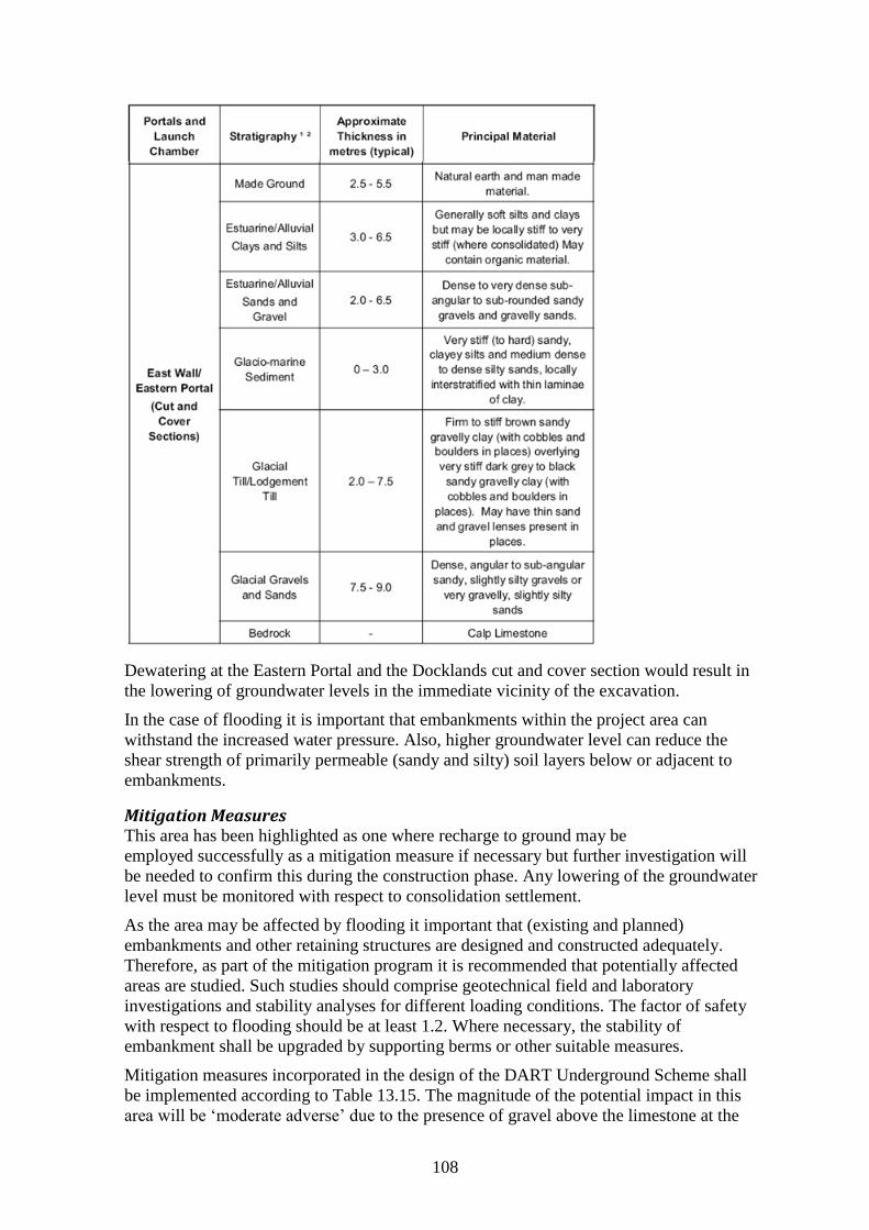
108
Dewatering at the Eastern Portal and the Docklands cut and cover section would result in
the lowering of groundwater levels in the immediate vicinity of the excavation.
In the case of flooding it is important that embankments within the project area can
withstand the increased water pressure. Also, higher groundwater level can reduce the
shear strength of primarily permeable (sandy and silty) soil layers below or adjacent to
embankments.
Mitigation Measures This area has been highlighted as one where recharge to ground may be
employed successfully as a mitigation measure if necessary but further investigation will
be needed to confirm this during the construction phase. Any lowering of the groundwater
level must be monitored with respect to consolidation settlement.
As the area may be affected by flooding it important that (existing and planned)
embankments and other retaining structures are designed and constructed adequately.
Therefore, as part of the mitigation program it is recommended that potentially affected
areas are studied. Such studies should comprise geotechnical field and laboratory
investigations and stability analyses for different loading conditions. The factor of safety
with respect to flooding should be at least 1.2. Where necessary, the stability of
embankment shall be upgraded by supporting berms or other suitable measures.
Mitigation measures incorporated in the design of the DART Underground Scheme shall
be implemented according to Table 13.15. The magnitude of the potential impact in this
area will be ‘moderate adverse’ due to the presence of gravel above the limestone at the
109
Docklands. The magnitude of the predicted impact will be ’small adverse’ and the
significance of the impact will be ’slight’.
Additional geotechnical investigations shall be performed to establish more reliably ground
conditions comprising suitable methods such as penetration tests and laboratory testing of
disturbed and undisturbed soil samples. Inventory of potentially contaminated soil and
groundwater shall be carried out. Monitoring of construction activities is particularly
important due to the extensive, deep excavations necessary in this area.
If the proposed mitigation measures are implemented the residual impact will be
negligible.
Monitoring shall be carried out during the construction phase to assure that specified
limiting values are not exceeded.
10.9 Comments and Recommendations – Geotechnical Impact
The environmental impact due to geotechnical conditions is important and needs to be
considered more thoroughly than in the EIS. Important information is contained in
Appendices to the EIS which should have been part of the main report. The impact due to
geotechnical conditions and construction activities was raised during Module 1 of the Oral
Hearing. The Applicant has responded comprehensively to all questions and provided
extensive information as evidence.
Geotechnical Impact
The Detailed Design stage, to be carried out in compliance with EN 1997 (Eurocode 7: Geotechnical design) shall include, inter alia, the following:
4. (i) The inclusion of the following geotechnical and geological hazards in the geotechnical risk assessment and management scheme:
variable and unexpected ground conditions (made ground and fill)
presence of soft, instable and compressive glacio-marine deposits
sand veins (interbedded as sandy laminations in boulder clay) causing dewatering problems
gravel bed resulting in problematic groundwater inflows into excavation
contamination of ground and groundwater
high levels of methane
artesian or sub-artesian water pressure within glacial gravels
instability of shallow excavations in loose and soft ground (especially silty soils)
settlement of structures and installations in the ground (e.g. utilities) due to tunnel construction
settlement of structures and installations in the ground due to permanent lowering of groundwater
ground movements (vertical and horizontal) of structures due to construction of deep excavations
instability of excavations in soil due to fissuring and/or shearing of glacial clays
instability of excavations in rock due to discontinuities, fissuring rock and weathered rock
variability of rockhead level or unexpected deviations from design assumptions
bedded limestone with interbedded shale resulting in stability problems
dip of limestone bedding
voids in rock formation (potential of karstic features)
high groundwater pressure at tunnel level
110
running sands in boulder clay
difficulties during tunnel boring in mixed face conditions
settlement of loose, granular soil layers induced by blasting vibrations
obstructions to excavations (made ground, boulders etc.)
inflow of water into excavations due to granular horizons
unexpected ground conditions
unexploded ordnance within soft or loose superficial deposits
consequences of archaeological excavations
contamination of groundwater.
5. Consideration of the following construction-related hazards:
Construction of water-tight wall elements due to construction deviations and/or obstructions
Seating of wall elements on blocks or fractured rock layers
Instability of excavations in rock due to unfavourable bedding planes
Leakage of groundwater in soil and fractured rock into deep excavations
TBM work in weathered rock and rock formations with potential faults
TBM work in mixed face conditions (soil-rock interface)
TBM work in deposits with layers and lenses of water-bearing sands
Wear on equipment (tunnelling and excavation) due to presence of abrasive ground
Obstructions in made ground encountered during wall construction (affecting verticality of piles/panels and influencing water tightness)
Chiselling required to penetrate boulders and other obstructions
Draw-down of groundwater adjacent to excavation, due excessive pumping in excavations (leakage through or below secant pile or diaphragm wall)
Difficulties with installation and/or retraction of ground anchors in hard rock
Implementation of ground treatment adjacent to tunnels and/or excavations.
6. Geotechnical investigations to include:
Rotary open hole and core investigations
Cone penetration testing (CPT) and in very soft soils with pore water pressure measurements (CPTU)
Laboratory testing to determine strength and stiffness of soil layers
Piezometer installation
Down-hole Geophysical testing including MASW and/or seismic refraction method logging
Contamination screening.
111
11 Vibration and Groundborne Noise
11.1 General
Vibration and groundborne noise can have potentially major environmental impact during
construction but also operation of the DART Underground. Groundborne noise, which
manifests itself as structural noise, propagates from the ground and into buildings. In the
EIS, vibration problems are discussed in two separate chapters. Chapter 8 deals with Above
Ground Vibrations and Noise and Chapter 9 with Below Ground Noise and Vibration.
However, the effects of vibrations from sources on or below the ground are similar and the
same assessment methods and mitigation measures apply. Therefore, both aspects are
treated in this chapter, which deals with all aspects of ground vibrations and groundborne
(structural) noise from sources on and below the ground surface.
In response to Note 1, attached to the Order of Proceedings of the Oral Hearing, the
Applicant gave a detailed presentation regarding below ground noise and vibration: OH-
No. 35; R. Greer: Below Ground Noise and Vibration and OH-No. 35A: Associated
PowerPoint presentation and evidence given by R. Greer on 15th
December 2010 OH-No. -
[sic]: Methods for predicting groundborne noise and vibration from trains and tunnels.
Different sources of vibration (such as the DART railway lines and the LUAS) exist and
affect buildings and their occupants along the DART Underground alignment. Therefore,
cumulative effects must be considered. However, this report addresses only such issues
which are relevant for the application of a Railway Order for the DART Underground.
11.2 Dynamic Soil Properties of Soil and Rock
Dynamic properties of soil and rock are important information required for the analysis
and prediction of vibrations and groundborne noise. Also the geological and geotechnical
conditions, such as soil layering and groundwater conditions, are of importance for
vibration propagation in the ground. This aspect has been addressed in previous sections of
this report.
The ground investigation programme carried out as part of the EIS involved in addition to
conventional geotechnical investigations also surface geophysical surveys (seismic
refraction and MASW profiling), cf. Chapter 8 and Chapter10. The information provided
in the EIS is valuable but has not been used in the evaluation of ground vibrations and
groundborne noise.
The results of seismic surveys inform about dynamic ground properties (material density,
speed of shear wave and compression wave) and their variation along and perpendicular to
the route. Factual data discussed in Chapter 9 suggest that stratification of soil and rock
layers is significantly more complex along some sections of the tunnel alignment than
assumed in the EIS. This is an important consideration and additional geotechnical
investigations and field trials are needed to calibrate theoretical predictions with field
observations.
112
11.3 Vibration Hazards
11.3.1 Enabling Works
Vibrations can be generated by enabling works, for instance the realignment of railway
tracks. The DART Underground alignment is traversed by railway lines forming part of the
existing freight line network. The existing tracks will have to be realigned in sequence with
the construction of the portal approach structures. Such work has the potential of
generating ground vibration but will, after completion, also reduce vibration levels and
thus improve the environmental conditions.
11.3.2 Construction Phase
Activities which can give rise to ground vibration during the construction phase are
discussed in the EIS in Chapters 8 and 9, respectively. Vibrations can primarily be caused
by excavation of soil and rock and by the movement of construction equipment,
compaction of soil and movement of heavy goods vehicles (HGVs) and supply trains.
If transport of spoils is carried out by rail, this increase of traffic can also lead to higher
ground vibrations.
The most important sources of vibration and groundborne noise during construction are
rock excavation by operation of the TBM and blasting. Each of the two TBMs is expected
to advance at the rate of about 75 to 100m per week, operating 7 days per week. The TBM
will only be experienced above each tunnel for a relatively short period which means that
higher impact thresholds can be applied than during the operational phase of the proposed
scheme. In locations between the two tunnels, this experience will be repeated with a delay
of a few weeks between the two tunnel drives. Because of the finite duration of this effect,
the night-time impact thresholds can be set slightly higher than those for the operation of
the proposed scheme.
Some underground construction within the limestone bedrock, for example the excavation
of cross passages, will be carried out by the use of drill and blast techniques. Other
potentially critical construction activities are chiselling and excavation of rock and
boulders during wall construction (diaphragm panels and bored piles).
11.3.3 Operational Phase
Vibration and groundborne noise can be caused by the operation of railway vehicles.
Groundborne vibration is generated by the dynamic forces at the wheel and rail interface.
The most important parameters are wheel/rail roughness, bogie unsprung mass, suspension
stiffness and speed. The train and track system ‘filters’ these dynamic forces, generally
reducing them, to a degree determined by the track design, causing the tunnel lining to
vibrate and hence causing the surrounding ground to vibrate.
A particular feature of the operation of a newly designed railway is incorporation of
resilient rail support and use of welded rail. By choosing during the design the appropriate
form of track support and provided that an adequate maintenance regime is followed,
significant effects due to vibration and groundborne noise can be avoided.
Vibrations propagate from the source (e.g. the tunnel) through rock and soil formations and
decay with increasing distance. However, soil layering, groundwater conditions and
dynamic properties of rock and soil all affect the direction and intensity of vibration
propagation and attenuation. Depending on the angle of impact and the frequency content
113
of the disturbance, vibrations can also be amplified on the ground surface and/or in
buildings.
Above ground railway traffic and in particular freight trains generate ground vibrations.
As part of the EIS vibration measurements were carried out and it is evident that such
vibrations have occurred historically. This aspect has been taken into account when
considering the cumulative impact.
11.4 Assessment of Ground Vibration
The impact of vibration and groundborne noise was assessed in the EIS based on empirical
evidence (construction phase) as well as on advanced semi-empirical and theoretical
models (operational phase). Both methods have advantages and limitations. Both methods
do not consider sufficiently the importance of dynamic ground properties and how these
affect vibration propagation. Therefore, empirical and theoretical prediction methods need
to be verified and calibrated against measurements and updated based on field trials.
The main sources of vibrations and associated hazards are discussed briefly in the
following sections.
11.4.1 Construction Phase
In Chapter 8 of the EIS, prediction of above ground vibrations from construction activities
is based on experience from vibration measurements reported in British Standard BS5228-
2 (2009) and measurements by consulting company AWN. As noted in Transport Research
Laboratory (TRL) Report 429, ‘Groundborne Vibration from Mechanised Construction
Works’ (2000) conventional construction works will generate substantially lower levels of
noise and vibration than blasting. Hence, they have been assessed qualitatively in the
context of the main underground construction activities.
Surface Construction Activities Excavation of soil by bored (auger) piling does normally generate vibration levels which
are low (soft soils) or medium (stiff soils with boulders). It is difficult to predict levels of
vibrations from pile installation. The most disturbing activities in connection with pile and
wall construction are hammer impact, chiselling, grinding or drilling. Therefore, it is
necessary to monitor ground vibrations during the initial phase of construction and to
develop site-specific correlations for prediction of ground vibrations.
A review of measured vibrations due to piling and vibroflotation/compaction activities has
been compiled from BS5228-2 (2009) and is presented in Volume 3 of the EIS, Table
A8.3.6. However, site-specific vibration predictions were not provided for pile and wall
panel excavation. Instead, prior to construction of piles or diaphragm wall panels close to
vibration-sensitive structures or installations, a detailed method statement including a work
schedule shall be prepared by the Contractor. Prediction of ground vibrations shall be made
in advance and verified by field trials, vibration measurement and by rigorous control
(using threshold and limiting values as outlined in Chapter 5 of this report).
TBM Operation A main sources of concern is tunnel boring and in particular the cutting action of the
shield. The lowest vibrations arise from tunnelling in clays and sands; tunnelling through
boulder clay and weak rock causes an intermediate level of vibration; TBM excavation of
more competent rock generates highest vibration levels. Vibrations are the result of actions
of different tools at the TBM within the ground. The amplitude, frequency and phase of the
114
waves arriving at the ground surface from each tool will be different; thus the peak
vibration is not simply a summation of the peak vibration from each tool.
Reliable assessment of TBM groundborne vibration is essential for developing robust
mitigation strategies. This topic was therefore discussed extensively during the Oral
Hearing where the Applicant provided additional evidence to the information given in the
EIS, explaining methods of analysis and prediction concepts, as described in TRL Report
429 (2000). The methodology is based upon measurements from tunnelling projects with
similar ground conditions. The empirical data include TBMs of a similar size to those
proposed for DART Underground. TRL Report 429 classifies measured vibration data
according to geological conditions (e.g. sands, clays, mixed sand & clays, and rock).
For the DART Underground project, vibration predictions were based on data from TBM
operation in rock assuming worst case conditions (e.g. boulders in boulder clay). This
conservative assumption is reasonable due to the fact that boulders can increase vibration
levels in boulder clay. Such predictions are considered to reflect the upper bound of
groundborne noise and vibration which can be expected.
The Contractor will be required to calibrate vibration predictions by field measurements
obtained for different geological and geotechnical conditions.
In the EIS, vibration predictions in terms of peak particle velocity (PPV) were converted to
Vibration Dose Values (VDVs) to reflect the assessment criteria presented in Chapter 9 of
the EIS. In making the conversion it was assumed that:
the TBM would be excavating for 50% of the day and night-time assessment
periods defined in the EIS (this is a typical worst case assumption for the
proportion of the working day when the TBM could be excavating);
the crest factor (ratio of PPV to the root mean square average vibration magnitude)
for TBM vibration is 4 – this is based on measurements over other TBM drives;
and
the frequency content of the TBM vibration velocity – which needs to be
understood as Vibration Dose Values are calculated from frequency weighted
vibration velocity – was taken form vibration measurements obtained over a
number of TBM drives, whilst the TBM was excavating.
The predicted levels of vibration (peak particle vibration, PPV) and groundborne noise (dB
LAmax,S derived from correlation with PPV ) were implemented using a Geographical
Information System (GIS). The results were applied directly to the alignment shown on the
railway order drawings and the ground model and building information, gathered for the
project as presented in the EIS.
TBM Supply Trains A similar prediction method as for the permanent operation of the DART Underground
Scheme was used, as discussed in a following section (cf. operational phase).
Drilling and Blasting Bulk excavation of cross passages will be by controlled blasting. Drill and blast techniques
may also be used to excavate station platforms, station connecting passages and the
underground elements of station boxes and shafts where these structures are to be
constructed in rock. The primary concern with blasting is to avoid building damage.
The principal source of vibration from blasting is the detonation of explosive charges
underground. Empirical techniques are generally used for predicting the vibration intensity
based on blast data from comparable geological conditions. Such relationships have been
115
developed between instantaneous charge weights and distance from the source. Based on
this information, site-specific correlations can then be developed using vibration
measurements from trial blasting. The intensity of vibration depends also on the location of
the source of vibration in relation to that of affected buildings. Predictions in the EIS are
based on a range of peak particle (PPV) values calculated from equations given in TRRL
Report 53 (1986). These equations were ‘fitted’ to measured vibration data gathered from
similar sites or from trials, a concept which is widely used, cf. British Standard, BS6472-2
(2008): Guide to Evaluation of Human Exposure to Vibration in Buildings, Part 2: Blast
Induced Vibration.
The geological and geotechnical conditions affect ground vibration propagation. Also the
geometry of the project site is important. Blasting directly below a building will generate
different types/frequencies of vibrations than blasting at some lateral distance from the
source. All three components of ground vibrations need to be measured when developing
site-specific attenuation relationships. These factors need to be assessed using blasting
tests.
11.4.2 Operational Phase
The main source of vibration and groundborne noise during the operational phase is trains
passing through tunnels and along railway embankments. Prediction of ground vibration
and groundborne noise is a challenging and complex task which requires competence in a
wide range of technical disciplines. The Applicant has demonstrated during the Oral
Hearing such extensive experience.
Train Traffic Rail systems of all types generate groundborne vibration and/or groundborne noise.
Groundborne vibrations created by train movements propagate through the ground to
surrounding buildings where these can result in vibration of floors, walls and ceilings;
these can also sometimes be heard as low frequency ‘rumbling’ noise (also called
structural-borne noise).
In addition to the DART Underground, existing freight train traffic generates vibrations.
The Applicant endeavours to improve the railway tracks and embankment stiffness of
existing railway lines. It is difficult to predict quantitatively the benefit of such mitigation
measures without vibration measurements. However, this improvement effort will without
doubt have a beneficial effect on the environment.
In the East Wall area, the existing freight line is elevated and the DART line will be inside
that line in a cut. It can be assumed that the predicted ground vibrations from the DART
Underground will be significantly lower in buildings at the ground surface than from
existing freight train operation. This is due to the type of track and the location of the
DART Underground track and the dynamic characteristics of the operating trains.
An assessment of likely ground vibrations and response of structures at different distances
from the source is required to predict environmental impact. This information is missing in
the EIS. There are no national or international standards that set out calculation
methodologies for groundborne noise and vibration from the operation of railways.
However, ISO 14837-1: 2005, provides guidance on the calculation and assessment of
railway groundborne noise and vibration.
Modelling of the likely intensity of vibration and groundborne noise from the operation of
train vehicles has been carried out using robust design and operational parameters for
vehicles. Assessment of vibration and groundborne noise from railway traffic must also
116
include mitigation measures which shall be included in the design and operation (including
maintenance) of the system.
Train Traffic in Tunnels Groundborne noise impact of the proposed DART Underground operation has been
calculated using the semi-empirical methods developed and validated initially for the
design and construction of High Speed 1 (HS1) in the UK, formerly known as Channel
Tunnel Rail Link (CTRL). The used method is primarily empirical but takes account of
many key parameters, including train design, train speed, track design, tunnel design,
tunnel depth, ground conditions, receiving building foundations and receiving building
type. A numerical method is used to calculate the vibration ‘filtering effect’ of the track
system including the rail design. This enables effective design development of the primary
form of groundborne noise mitigation: the track system. The semi-empirical procedures
were validated against extensive measurements of vibrations from high-speed, intercity,
and mass transit railways (in accordance with ISO 14837-1).
It is noted that the present model does not include the effect of wave propagation through
geological formations (soil and rock layers, groundwater). Therefore, it is essential that the
model is calibrated against vibration measurements from different locations along the
DART Underground.
11.5 Impact Criteria
11.5.1 General
In order to be able to assess the environmental impact from different vibration sources on
receptors along the DART Underground route it is necessary to establish limits for
vibrations and groundborne noise.
In the absence of international standards regarding ground vibrations and their impact on
buildings and humans, in the EIS impact criteria (limiting values) have been based on the
following British Standards (BS):
BS 5228-2:2009. “Code of practice for noise and vibration control on construction
and open sites – Part 2: Vibration”. Part 2 informs about vibrations caused by
above ground surface construction works, including rock breaking, piling etc.
BS 6472-1:2008. “Guide to evaluation of human exposure to vibration in buildings
Part 1: Vibration sources other than blasting” gives detailed guidance on human
response to vibration in buildings.
BS 6472-2: 2008. “Guide to evaluation of human exposure to vibration in
buildings Part 2: Blast-induced vibration” gives detailed guidance on human
response to blasting.
BS 7385-1:1990. “Evaluation and measurement for vibration in buildings. Guide
for measurement of vibrations and evaluation of their effects on buildings” covers
the measurement and evaluation of structural vibration.
BS 7385-2: 1993. “Evaluation and measurement for vibration in buildings — Part
2: Guide to damage levels from groundborne vibration”. Part 2 gives guidance on
damage levels from groundborne vibration.
Guidance with regard to assessment of vibration and groundborne noise from railway
traffice can also be found in the ISO standard (ISO 14837-1:2005, IDT): “Mechanical
vibration – Groundborne noise and vibration arising from rail systems – Part 1: General
guidance”. For the evaluation of vibration in buildings with respect to comfort and
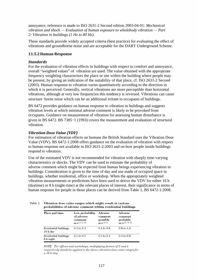
117
annoyance, reference is made to ISO 2631-2 Second edition 2003-04-01: Mechanical
vibration and shock — Evaluation of human exposure to wholebody vibration — Part
2: Vibration in buildings (1 Hz to 80 Hz).
These standards provide widely accepted criteria (best practice) for evaluating the effect of
vibrations and groundborne noise and are acceptable for the DART Underground Scheme.
11.5.2 Human Response
Standards For the evaluation of vibration effects in buildings with respect to comfort and annoyance,
overall “weighted values” of vibration are used. The value obtained with the appropriate
frequency weighting characterizes the place or site within the building where people may
be present, by giving an indication of the suitability of that place, cf. ISO 2631-2 Second
(2003). Human response to vibration varies quantitatively according to the direction in
which it is perceived. Generally, vertical vibrations are more perceptible than horizontal
vibrations, although at very low frequencies this tendency is reversed. Vibrations can cause
structure‑borne noise which can be an additional irritant to occupants of buildings.
BS 6472 provides guidance on human response to vibration in buildings and suggests
vibration levels at which minimal adverse comment is likely to be provoked from
occupants. Guidance on measurement of vibration for assessing human disturbance is
given in BS 6472. BS 7385‑1 (1993) covers the measurement and evaluation of structural
vibration.
Vibration Dose Value (VDV) For estimation of vibration effects on humans the British Standard uses the Vibration Dose
Value (VDV). BS 6472-1:2008 offers guidance on the evaluation of vibration with respect
to human response not available in ISO 2631-2:2003 and on how people inside buildings
respond to vibration.
Use of the estimated VDV is not recommended for vibration with sharply time-varying
characteristics or shocks. The VDV can be used to estimate the probability of
adverse comment which might be expected from human beings experiencing vibration in
buildings. Consideration is given to the time of day and use made of occupied space in
buildings, whether residential, office or workshop. When the appropriately weighted
vibration measurements or predictions have been used to derive the VDV for either 16 h
(daytime) or 8 h (night-time) at the relevant places of interest, their significance in terms of
human response for people in those places can be derived from Table 1, BS 6472-1:2008.
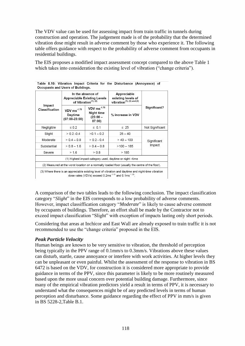
118
The VDV value can be used for assessing impact from train traffic in tunnels during
construction and operation. The judgement made is of the probability that the determined
vibration dose might result in adverse comment by those who experience it. The following
table offers guidance with respect to the probability of adverse comment from occupants in
residential buildings.
The EIS proposes a modified impact assessment concept compared to the above Table 1
which takes into consideration the existing level of vibration (“change criteria”).
A comparison of the two tables leads to the following conclusion. The impact classification
category “Slight” in the EIS corresponds to a low probability of adverse comments.
However, impact classiffication category “Moderate” is likely to cause adverse comment
by occupants of buildings. Therefore, an effort shall be made by the Contractor not to
exceed impact classification “Slight” with exception of impacts lasting only short periods.
Considering that areas at Inchicor and East Wall are already exposed to train traffic it is not
recommended to use the “change criteria” proposed in the EIS.
Peak Particle Velocity Human beings are known to be very sensitive to vibration, the threshold of perception
being typically in the PPV range of 0.1mm/s to 0.3mm/s. Vibrations above these values
can disturb, startle, cause annoyance or interfere with work activities. At higher levels they
can be unpleasant or even painful. Whilst the assessment of the response to vibration in BS
6472 is based on the VDV, for construction it is considered more appropriate to provide
guidance in terms of the PPV, since this parameter is likely to be more routinely measured
based upon the more usual concern over potential building damage. Furthermore, since
many of the empirical vibration predictors yield a result in terms of PPV, it is necessary to
understand what the consequences might be of any predicted levels in terms of human
perception and disturbance. Some guidance regarding the effect of PPV in mm/s is given
in BS 5228-2,Table B.1.
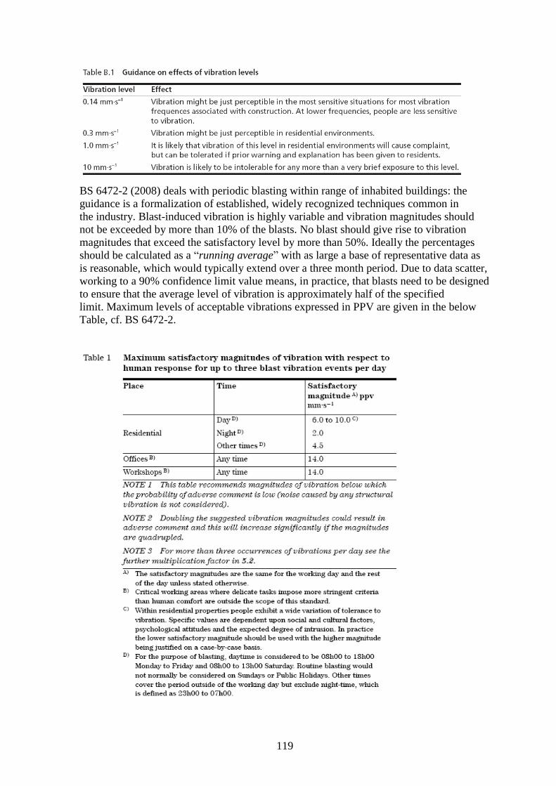
119
BS 6472-2 (2008) deals with periodic blasting within range of inhabited buildings: the
guidance is a formalization of established, widely recognized techniques common in
the industry. Blast-induced vibration is highly variable and vibration magnitudes should
not be exceeded by more than 10% of the blasts. No blast should give rise to vibration
magnitudes that exceed the satisfactory level by more than 50%. Ideally the percentages
should be calculated as a “running average” with as large a base of representative data as
is reasonable, which would typically extend over a three month period. Due to data scatter,
working to a 90% confidence limit value means, in practice, that blasts need to be designed
to ensure that the average level of vibration is approximately half of the specified
limit. Maximum levels of acceptable vibrations expressed in PPV are given in the below
Table, cf. BS 6472-2.
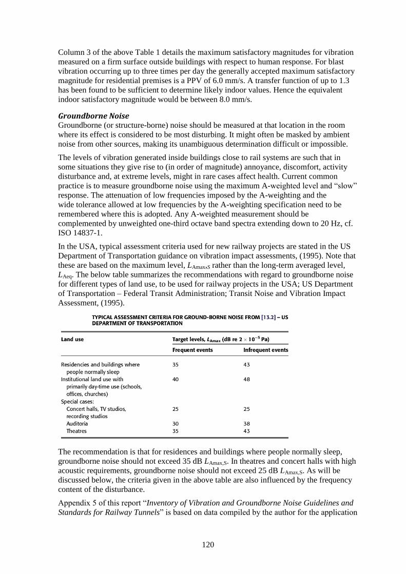
120
Column 3 of the above Table 1 details the maximum satisfactory magnitudes for vibration
measured on a firm surface outside buildings with respect to human response. For blast
vibration occurring up to three times per day the generally accepted maximum satisfactory
magnitude for residential premises is a PPV of 6.0 mm/s. A transfer function of up to 1.3
has been found to be sufficient to determine likely indoor values. Hence the equivalent
indoor satisfactory magnitude would be between 8.0 mm/s.
Groundborne Noise Groundborne (or structure-borne) noise should be measured at that location in the room
where its effect is considered to be most disturbing. It might often be masked by ambient
noise from other sources, making its unambiguous determination difficult or impossible.
The levels of vibration generated inside buildings close to rail systems are such that in
some situations they give rise to (in order of magnitude) annoyance, discomfort, activity
disturbance and, at extreme levels, might in rare cases affect health. Current common
practice is to measure groundborne noise using the maximum A-weighted level and “slow”
response. The attenuation of low frequencies imposed by the A-weighting and the
wide tolerance allowed at low frequencies by the A-weighting specification need to be
remembered where this is adopted. Any A-weighted measurement should be
complemented by unweighted one-third octave band spectra extending down to 20 Hz, cf.
ISO 14837-1.
In the USA, typical assessment criteria used for new railway projects are stated in the US
Department of Transportation guidance on vibration impact assessments, (1995). Note that
these are based on the maximum level, LAmax,S rather than the long-term averaged level,
LAeq. The below table summarizes the recommendations with regard to groundborne noise
for different types of land use, to be used for railway projects in the USA; US Department
of Transportation – Federal Transit Administration; Transit Noise and Vibration Impact
Assessment, (1995).
The recommendation is that for residences and buildings where people normally sleep,
groundborne noise should not exceed 35 dB LAmax,S. In theatres and concert halls with high
acoustic requirements, groundborne noise should not exceed 25 dB LAmax,S. As will be
discussed below, the criteria given in the above table are also influenced by the frequency
content of the disturbance.
Appendix 5 of this report “Inventory of Vibration and Groundborne Noise Guidelines and
Standards for Railway Tunnels” is based on data compiled by the author for the application
121
for a Railway Order for the Metro North. It demonstrates that in many countries, vibrations
from operational train traffic affecting residential areas is not permitted to exceed 35 dB
LAmax,S night-time.
Theatres and Concert Halls Noise and vibration impact can occur during the construction as well as the operation of
the DART Underground Scheme. Some buildings, such as concert halls, TV and recording
studios and theatres, can be (but not necessarily are) very sensitive to vibration and noise.
Sensitivity to noise and vibration depends on the structural conditions, the acoustic
properties of the auditorium and the type of performance. Because of the potential
sensitivity of such buildings, they usually warrant special attention.
The enforcement of low noise levels will be critical to the uninterrupted operation of
sensitive receptors such as theatres. During the construction phase, short-term, temporary
significant adverse effects have been identified in the EIS at the following non-residential
receptors:
Marconi House broadcast facilities (approx. 15 days per TBM drive).
The Gaiety Theatre (approx. 20 days per TBM drive).
Grand Canal Theatre (approx. 20 days per TBM drive).
The Grand Canal Theatre (GCT) accommodates world-class performances of drama and
classical music. The current back-ground noise conditions in the auditorium are of high
standard and create a very low noise environment. Also the other two premises are deemed
to be sensitive to groundborne noise. In the EIS, Chapter 9.5.1.2 the Applicant propose
with respect to operation of the TBM the following mitigation measure:
The Contractor will be obliged to implement a mitigation strategy (at either source or receptor) for the significant adverse effect on residential properties at Inchicore; Marconi House; Gaiety Theatre; and Grand Canal Theatre, in order to reduce or remove, in so far as is reasonably practicable
2, the
adverse groundborne noise effect at night time for residential properties and during critical operational times (e.g. performance broadcast and critical rehearsal times) for non-residential property.
In the EIS, Chapter 9.5.1.4 the Applicant proposed with respect to blasting the following
mitigation measure:
The Contractor will be obliged to implement a mitigation strategy (at either source or receptor) for Marconi House, Gaiety Theatre and Grand Canal Theatre in order to reduce or remove, in so far as is reasonably practicable, the adverse groundborne noise effect during critical operational times (e.g. performance broadcast and critical rehearsal times).
In the EIS, Table 9.11 the Applicant summarises temporary residual groundborne noise
impacts and effects on non-residential premises from construction activities.
The Significance Criteria proposed for the two theatres is 25 dB LAmax,S and for Marconi
House 30 dB LAmax,S, respectively.
In the EIS, Table 9.13 the Applicant predicted for the operational phase and sensitive non-
residential receptors groundborne vibration levels and proposed Significance Criteria.
2 Emphasis added by the author of this report.
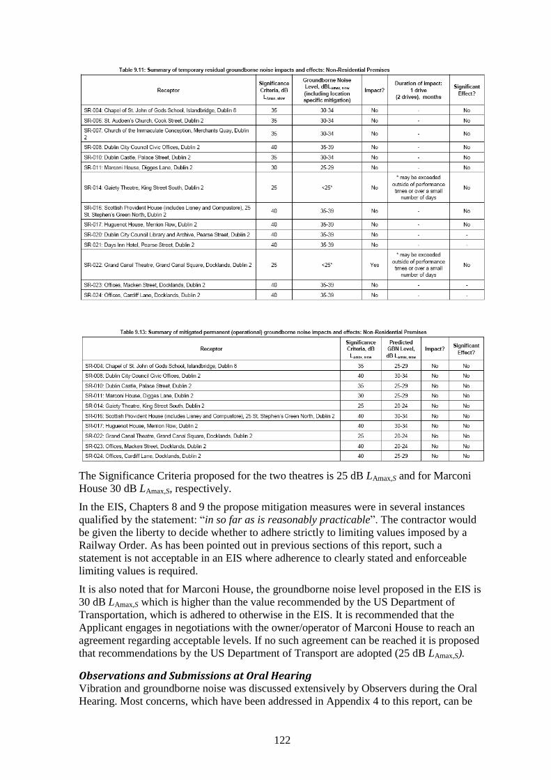
122
The Significance Criteria proposed for the two theatres is 25 dB LAmax,S and for Marconi
House 30 dB LAmax,S, respectively.
In the EIS, Chapters 8 and 9 the propose mitigation measures were in several instances
qualified by the statement: “in so far as is reasonably practicable”. The contractor would
be given the liberty to decide whether to adhere strictly to limiting values imposed by a
Railway Order. As has been pointed out in previous sections of this report, such a
statement is not acceptable in an EIS where adherence to clearly stated and enforceable
limiting values is required.
It is also noted that for Marconi House, the groundborne noise level proposed in the EIS is
30 dB LAmax,S which is higher than the value recommended by the US Department of
Transportation, which is adhered to otherwise in the EIS. It is recommended that the
Applicant engages in negotiations with the owner/operator of Marconi House to reach an
agreement regarding acceptable levels. If no such agreement can be reached it is proposed
that recommendations by the US Department of Transport are adopted (25 dB LAmax,S).
Observations and Submissions at Oral Hearing Vibration and groundborne noise was discussed extensively by Observers during the Oral
Hearing. Most concerns, which have been addressed in Appendix 4 to this report, can be
123
taken into account by applying the restrictions recommended in this report. Of particular
relevance is the long-term effect of groundborne noise during the operational phase of the
DART Underground.
GCT objected to the method of assessing groundborne noise in the EIS, Chapter 9 and to
the proposed limiting values. Reference was made during the Oral Hearing by GCT to an
acoustic tests carried out at the GCT to assess the significance of the proposed criteria. The
following observations submitted:
OH-No. 175, M. Adamson: Grand Canal Theatre Company.
OH-No. 175A, John Spain Associates: Planning.
OH-No. 175B, Slides
OH-No. 175C, Civil Engineering Aspects, O’Connor Sutton Cronin.
OH-No. 175D, Noise and Vibration, Marshall Day Acoustics.
The main concern of GCT was whether the significance criterion proposed in the EIS (25
dB LAmax,S) was sufficient to prevent interference with certain performances and other
related activities in the GCT. The matter of building acoustics and the definition of limiting
values is complex as such criteria are dependent on the frequency content of the
disturbance. The response of buildings and building elements can be highly sensitive to
excitation at different frequencies. For example, vibrations with different frequency spectra
can meet the same limiting value when expressed as a single dB-value. Thus the frequency
distribution of the disturbance entering the foundation of a building is an important
parameter. This aspect was discussed during the Oral Hearing in great detail between and
with the Applicant and the Observer, in order to clarify the assumptions made in their
evidence and submissions.
In Evidence given by the Applicant (OH-No. 35, R. Greer: Below Ground Noise and
Vibration) the following clarification was given:
To further refine the mitigation commitment in the EIS, for the for the [sic] different noise and vibration sources (e.g. TBMs, TBM supply trains, and controlled blasting) the contractor will be required to:
Confirm with the venue the indicative timing of the below ground works that could cause noise or vibration in the venue at least six months in advance;
Liaise regularly with the venue operators to confirm the look ahead programme of noise / vibration sensitive activities within the venue;
Confirm the likely levels of below ground noise and vibration to be generated by the contractor’s proposals as part of relevant Noise and Vibration Control Plan (NVCP) – refer to section 9.5.1.1 of the EIS – that will demonstrate that the proposed works will comply with the relevant EIS criteria and which will also examine and bring forward any reasonable and practicable means to further minimise the noise and vibration forecast at the venues;
Ensure, by monitoring, that the noise generated by any works undertaken during sensitive activities in the venues is less than the relevant criteria set out in Tables 9.2, 9.3, 9.4 and 9.5 of the EIS during sensitive activities within the venue;
For the theatres, schedule and stop the relevant construction activities during noise / vibration sensitive activities where the above criteria cannot be met and ensure there is no significant increase in settlement arising from stoppage (this would involve scheduling works so that maintenance or low intensity works are completed during the performance period and thereafter normal works would recommence outside of times when sensitive activities within the theatres take place); and
for Marconi House broadcasting facilities enact the contingency plan being developed by the operators during construction activities where the agreed criteria cannot be met (the approach to Marconi House differs from the theatres because the facility includes noise
124
and vibration mitigation within the design of parts of the facility that is likely to protect internal noise levels during the works).
In response to the assessment criteria given in the EIS, GCT and their experts proposed
significantly more restrictive “ideal” criterion that they felt would cause no disturbance, cf.
OH-No. 174B, GCT, represented by Marshall Day Acoustics: Grand Canal Square - Noise
and Vibration. Subsequently, GCT experts offered a “compromise” criterion at which
noise and groundborne noise levels would still be acceptable to GCT. For technical details
reference is made to the submissions by GCT (OH-No. 203, Grand Canal Theatre Noise &
Vibration Test Proposal - Grand Canal Theatre; and OH-No. 203A, Document detailing
Qualifications & Experience of Sound Engineer conducting tests - Listening Tests at GCT).
The Applicant and GCT agreed to carry out at the GCT - for the benefit of ABP Experts - a
series of Listening Tests under controlled conditions. Separate test programs were
elaborated by the Applicant and GCT; for details reference is made to the following
documents:
OH-No. 202, C.I.E.: Grand Canal Theatre: Noise & Vibration Test Proposal.
OH-No. 203, Grand Canal Theatre: Grand Canal Theatre Noise & Vibration Test
Proposal.
The scope, implementation and technical details of the two sets of acoustic tests are not
repeated in this report and reference is made to evidence presented at the Oral Hearing.
It was agreed that both parties were allowed to attend, record and analyse both Listening
Tests. In addition, in order to assure that the requirements with respect to planning,
recording and evaluation of the tests met highest standards, two independent experts
chosen by the Applicant and GCT, respectively, attended, inspected, evaluated and
commented on the test results.
The Listening Test was undertaken on 31th
March 2011 and attended by ABP Experts to
experience different scenarios of the type and intensity of noise (simulated groundborne
noise) which can be expected from the operation of DART Underground. In addition to
representatives of the Applicant and GCT, the Applicant also invited 51 “uninformed”
attendants to experience the (simulated) performance of Shakespeare’s Hamlet. After the
performance, the 51 members were asked to reply to a written questionnaire, assessing
ambience, background and noise during the performance and to remark on any noted
disturbance. The results of the Listening Tests were reported to the Oral Hearing on 7th
April 2011:
Report submitted by Arup on behalf of CIE DART Underground: OH-No. 223;
Demonstration of Train Noise at Grand Canal Theatre - CIE.
Report submitted by Peutz Consulting on behalf of Arup: Grand Canal Theatre:
OH-No. 223A; Peutz Review on the methodology of the Noise Test.
Arup: OH-No. 223B;Figure 16: Comparison of spectral content and
Arup: OH-No.223C; Millward Brown Lansdowne Focus group.
Report submitted by Marshall Day on behalf of Gran Canal Theatre: OH-No. 224;
Marshall Day Acoustics Report Grand Canal Theatre – Listening tests.
OH-No. 224B Memo Marshall Day: Response to questions raised by Fred Walsh.
Report submitted by Engineered Acoustic Design on behalf of Marshall Day: OH-
No.224A; Engineered Acoustic Designs, Report of Witnessed Listening Tests.
For details on the acoustic measurements, analyses and tests evaluation, reference is made
to the above listed documents submitted to ABP by GCT and the Applicant.
125
Based on the listening tests, ABP experts carried out a careful evaluation of the results also
considering the different types of vibration scenario that were experienced during the
Listening Test. It is recommended that the criteria proposed by the Applicant – and
including the clarifications and assurances given during the Oral Hearing, shall be the
upper limit of permissible vibrations and ground-borne noise. Extensive field tests shall be
carried out during the construction of the DART Underground below the GCT to further
investigate vibration amplification and response from realistic sources such as TBM boring
and operation of supply trains. Further, it is recommended to carry out a field trial of the
track design to verify that the predicted levels of ground vibrations and ground-borne noise
are not exceeded.
The Applicant and GCT are commended for their efforts in competent planning and
professional implementation of the Listening Tests. Within very short time, the results of
comprehensive measurements were analysed and evaluated and submitted in written
format prior to their presentation at the Oral Hearing. The Listening Tests contributed
significantly to a better understanding of this problematic technical issue.
11.5.3 Utilities
The following criteria taken from BS52288-2 are proposed and acceptable for utilities:
Intermittent and transient vibrations: PPVmax: 30mm/s
Continuous vibrations: PPVmax: 15mm/s
11.5.4 Vibration-sensitive Equipment and Processes
There are no generally applicable standards for assessing the potential impact of vibration
on sensitive equipment or processes. For each receptor which has been identified within
the area of influence (200m) a specific assessment shall be made, taking into account the
sensitivity of each receptor.
A submission was made by Masterlab’s (OH-No. 96, A. Foley and Masterlabs Ltd) stating
that the planned DART Underground would severely interfere with their recording and
mastering business. The studio comprises an interior structure inside an exterior shell and
contact between the two structures is minimised in order to limit transmission of outside
vibrations. The present activities are already affected by vibrations from the existing
railway traffic and sensitive mastering work must be interrupted when freight trains pass. It
is claimed that the additional DART Underground traffic would have fatal impact on
Masterlab’s business.
The upgrading of existing freight lines with welded rail and improved track conditions
shall reduce the present level of ground vibrations. Traffic from operation of the DART
Underground is not considered to worsen the existing vibration level as the DART will
operate in a cut and at a greater distance than the existing freight lines.
The Trinity Bioscience Institute houses vibration-sensitive equipment as well as animals,
cf. S-No. 144, Trinity College Dublin (Paul Mangan); 2010-08-18, 104-105. Blasting and
other construction work will be carried out which can potentially affect the institute.
The EIS has identified the institute as a potentially vibration-sensitive receptor. The
predicted levels of groundborne noise are, however, low (unmitigated: 25 -29 dB LAmax,S
during construction and 20 - 24 dB LAmax,S ). Due to the importance of the building and the
activities it houses, it is necessary to confirm by vibration tests and monitoring that the
predicted levels will not be exceeded.
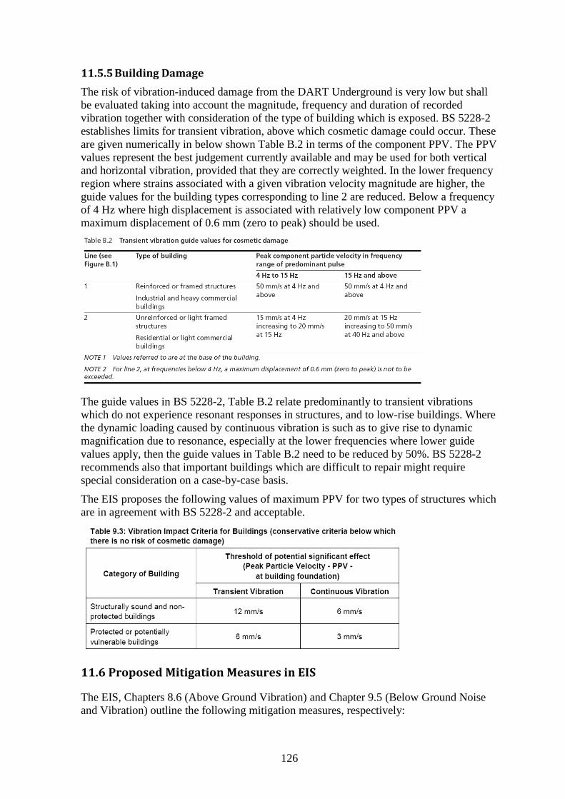
126
11.5.5 Building Damage
The risk of vibration-induced damage from the DART Underground is very low but shall
be evaluated taking into account the magnitude, frequency and duration of recorded
vibration together with consideration of the type of building which is exposed. BS 5228-2
establishes limits for transient vibration, above which cosmetic damage could occur. These
are given numerically in below shown Table B.2 in terms of the component PPV. The PPV
values represent the best judgement currently available and may be used for both vertical
and horizontal vibration, provided that they are correctly weighted. In the lower frequency
region where strains associated with a given vibration velocity magnitude are higher, the
guide values for the building types corresponding to line 2 are reduced. Below a frequency
of 4 Hz where high displacement is associated with relatively low component PPV a
maximum displacement of 0.6 mm (zero to peak) should be used.
The guide values in BS 5228-2, Table B.2 relate predominantly to transient vibrations
which do not experience resonant responses in structures, and to low-rise buildings. Where
the dynamic loading caused by continuous vibration is such as to give rise to dynamic
magnification due to resonance, especially at the lower frequencies where lower guide
values apply, then the guide values in Table B.2 need to be reduced by 50%. BS 5228-2
recommends also that important buildings which are difficult to repair might require
special consideration on a case-by-case basis.
The EIS proposes the following values of maximum PPV for two types of structures which
are in agreement with BS 5228-2 and acceptable.
11.6 Proposed Mitigation Measures in EIS
The EIS, Chapters 8.6 (Above Ground Vibration) and Chapter 9.5 (Below Ground Noise
and Vibration) outline the following mitigation measures, respectively:
127
Above Ground Vibration
8.6 Mitigation Measures
The key mitigation measures applied to vibration sources for DART Underground are the range of criteria which have been set in order to prevent any significant impacts. The mitigation measures set out in this section are those recommended in order to achieve these criteria based on the proposed works and operational programme. Should the Contractor construct or operate the proposed scheme using alternative means, identical criteria will have to be met.
8.6.1 General
The proposed scheme has, where possible, designed a construction programme to avoid and reduce environmental impacts as is best practicable. In terms of above ground noise and vibration, the construction methodology proposed at station and shaft constructions sites has an inherent mitigation measure incorporated into the design through partially enclosing excavation and construction works beneath the roof slabs.
Mitigation measures set out in this Section are those additional measures which are deemed necessary to further reduce identified negative impacts. The impact assessment conducted for the construction phase has highlighted the requirement for mitigation to be implemented at the majority of construction sites in order to reduce the noise impact to nearby noise sensitive areas.
The Contractor will compile the following plans:
The Noise and Vibration Management Plan (NVMP) which will deal specifically with management processes and strategic (route wide) mitigation measures to remove or reduce significant noise and vibration effects. As part of the NVMP the Contractor will prepare and agree with the contractor for Dublin Metro North a common management process to ensure that cumulative noise and vibration effects from DART Underground and Dublin Metro North sources do not exceed the construction noise and vibration thresholds. Cumulative noise and vibration effects from different DART Underground sources shall also be addressed as part of the NVMP. The Plan will also define noise and vibration monitoring and reporting this will form part of the Environmental Management Plan. The mitigation measures detailed below will form part of the Noise and Vibration Management Plan.
The Noise and Vibration Control Plans which will be based on and include method statements for each area of the works, the associated specific measures (to be at least those from the NVMP) to minimise noise and vibration in so far as is reasonably practicable for the specific works covered by each plan and a detailed appraisal of the resultant construction noise and vibration generated.
Below Ground Noise and Vibration
Mitigation measures with respect to below ground noise and vibration are described as
follows:
9.5 Mitigation Measures
The design development of the base scheme and its alignment has included the need to reduce environmental impact in so far as is reasonably practicable.
The following sections set out the mitigation proposed to reduce or remove the significant adverse effects identified for the base scheme as reported in Section 9.4.
9.5.1 Construction
9.5.1.1 General
(same as 8.6.1)
…..
Prior to the commencement of any works on site, the Contractor will implement a mitigation strategy (at source – for all DART Underground noise and vibration sources - or receptor) at Marconi House, Gaiety Theatre and Grand Canal Theatre in order to reduce or remove, in so far as is reasonably practicable, the adverse groundborne noise effects from DART Underground works
128
during critical operational times (e.g. performance, broadcast and critical rehearsal times).
9.5.1.2 TBMs
The Contractor will be obliged to implement a mitigation strategy (at either source or receptor) for the significant adverse effect on residential properties at Inchicore; Marconi House; Gaiety Theatre; and Grand Canal Theatre, in order to reduce or remove, in so far as is reasonably practicable , the adverse groundborne noise effect at night time for residential properties and during critical operational times (e.g. performance broadcast and critical rehearsal times) for non-residential property.
As discussed previously, it is not acceptable to limit the obligation and responsibility of the
contractor by introducing the vague phrase “in so far as is reasonably practicable”.
11.7 Comments and Recommendation – Vibration and Groundborne Noise
EIS Chapters 8 and 9 assesses the impact of vibration and groundborne noise arising from
the construction and operation of the proposed scheme. The concepts used to assess ground
vibrations from different vibration source during construction and operation were
discussed extensively during the Oral Hearing. In response to Note 1, attached to An Board
Pleanála’s Oral Hearing – Order of Proceedings, the Applicant’s experts prepared detailed
and convincing presentations on prediction of groundborne noise and vibration. However,
the EIS does not address in detail the need for additional ground investigations during
construction and operation. Also the need of field testing and trials during the construction
phase must be emphasised.
The mitigation measures proposed in the EIS are otherwise considered adequate and shall
be applied with the recommended modifications. The “Noise and Vibration Management
Plan” (NVMP) and the “Noise and Vibration Control Plans” (NVCPs) are essential
elements of the environmental risk assessment program. These will be supplemented by an
extensive monitoring scheme as outlined above. Vibration measurements shall be made
during construction and operation of the DART Underground. In addition, full-scale tests
are required at sensitive receptors to verify that predicted values are not exceeded.
I. General Recommendations
4. Limiting values stated for vibration and groundborne noise shall be based - without modification - on relevant British Standards, where applicable. The application of “change base criteria” shall not apply.
5. As part of the Noise and Vibration Monitoring (NMV) program, the contractor shall be required to work out specific method statements for construction work which can give rise to significant ground vibrations. Field trials and tests shall be carried out by the contractor in advance of critical activities. Vibration levels shall be predicted and compared with measured values.
6. Vibration measurements shall be carried out on the ground and inside of vibration-sensitive buildings. A detailed field measurement program shall be worked out by experienced specialists. All tests shall be carried out in cooperation with, or under supervisions by, the engineering team of the Applicant and independent experts.
II. Impact Criteria - Construction Phase
3. Vibration impact on humans is based on BS 6472-1:2008 Table 1. VDV levels proposed in the EIS are acceptable in principle as upper limits for the construction phase. During night-time, VDV levels shall not exceed: < 0.2 m.s-1.75 having low probability of adverse comment. (This can be accomplished in many cases by field trials and modification of
129
working methods with potential of causing disturbance.) Higher VDV values shall be accepted only for a short duration (less than 10 minutes) when unexpectedly difficult ground conditions are encountered.
4. When measured vibration levels from TBM works exceed 49 dB LAmax,S during night time, occupants of buildings shall be offered without delay alternative accommodation (or, if agreeable to the contractor and affected party, other form of mitigation). The threshold level of vibration monitoring during TBM operation night-time shall be 45 dB LAmax,S S. When groundborne noise is predicted to exceed 45 dB dB LAmax,S S during night time the contractor shall in cooperation with the Applicant work out an action plan to minimize ground vibrations. An attempt shall be made to modify the construction processes and phasing of work with the aim of reducing groundborne noise to values below 45 dB LAmax,S S.
III. Impact Criteria - Operational Phase
4. Groundborne noise during night-time in residential areas shall not exceed 35 dBA.
5. Vibration levels shall not exceed VDV belonging to the category of low probability of adverse comments: 0.2 to 0.4 m.s-1.75 (day-time) and 0.1 to 0.2 m.s -1.75 (night-time).
6. For Theatres and Marconi House: limits of vibrations and of groundborne noise proposed in the EIS shall be modified according to the evidence given by the Applicant during the Oral Hearing. The EIS criterion of 25 dB LAmax,S shall be imposed as an absolute and upper limit according to the frequency distribution defined by the Applicant. The 25 dB LAmax,S criterion applies to 100% of trains. Field trials shall be carried out after construction of the tunnels to verify vibration propagation to sensitive receptors. An effort should be made by the Contractor to design the railway track to achieve a lower value than 25 dB LAmax,S.