Embed Size (px)
Citation preview

ST3400H
Helicopter
Terrain Awareness Warning System
Installation Manual
Sandel Avionics 2401 Dogwood Way
Vista, CA 92081 Phone (760) 727-4900 FAX (760) 727-4899
Website: www.sandel.com
Email: [email protected]
82046-IM-J

[This page intentionally left blank]
82046-IM-J ST3400H INSTALLATION MANUAL Page ii
Revision History
Revision Date Comments J 8/19/2015 REVISED IAW AR 2107
Section 6.8: Updated to include APN-209. Cal note updated. Section 8.3: Updated to include APN-209 Section 12: List of effective drawings updated.
H 07-06-2015 REVISED IAW AR 1477 Section 1.2: Added notes to limitations regarding installation location and electrical interconnection information. Section 1.4.1: Removed user-defined obstacle provision statement. Section 1.6: Formatting updated. Section 1.6.1: Approval data updated. ETSO data added. Section 1.6.2: Weight spec updated. Section 1.7: Formatting updated. Section 2: Updated section title to Installation Planning and Procedures. Section 2.2: Updated to include equipment Section 2.2.1: Updated to include equipment. Added Audio system. Section 2.2.3: Added note describing North Up display with no heading and track while in maintenance mode. Section 2.3 Reformatted. Added additional steps to Pre-Installation Planning. Section 2.4 Added Installation Section 2.5: Was Section 2.4 - Added additional Post Installation steps. Section 3.3: Added note describing North Up display with no heading and track while in maintenance mode. Section 4.3.2: Updated human factors section. Section 4.3.3: Changed the word diagrams to drawings. Section 4.3.4: New section: Mounting locations. Section 4.4: Reformatted. Updated ground bonding note. Section 5.4: Updated to show that the CM functionality is reserved for future use. Added text to advise leaving CM plugged in. Section 5.5: Updated to show that the CM functionality is reserved for future use. Section 6: Retitled to “System Configuration.” Section 6.11: Added note for when to configure the ST3400H using the (SW) setting. Section 6.14: Added text for Mode 1 arming altitude. Corrected axis titles on Standard Mode-1 curve.
82046-IM-J ST3400H INSTALLATION MANUAL Page iii
Section 7: Added return to service statement at beginning of chapter. Section 7.8: Heading clarified as “Optional Interface”. N/A column added. Section 7.9: Heading clarified as “Optional Interface”. N/A column added. Clarified Result text for Heading Value. Section 7.10: Heading clarified as “Option Configuration”. Text added to indicate NVIS may require additional installation approval. Additional inputs added. N/A Column added. Section 7.11: Heading clarified as “Optional Interface”. N/A column added. Section 7.12: Heading clarified as “Optional Interface”. N/A column added. Section 7.13: Heading clarified as “Required”. Sections 7.14: Heading clarified as “Optional Interface”. N/A column added. Section 7.15: Heading clarified as “Optional Interface”. N/A column added. Clarified Result text to add that audio should also be heard. Section 7.16: Heading clarified as “Optional Interface”. Section formatting updated. Section 7.17: Heading clarified as “Optional Interface”. Section formatting updated. Section updated for new SENS mode functionality. Section 7.18: Section formatting updated. Section 7.19: Heading clarified as “Optional Interface”. Section formatting updated. Section 7.20: Section formatting updated. Section 7.21: Test step updated for clarity. Section formatting updated. Section 7.22: Test step updated. Section formatting updated. Section 7.23: Section formatting updated. Section 7.24: New content. Section 7.25: New content. Section 8.2: Changed KLN-90 to KLN-90B (ARINC 429). Section 8.3: Added KRA-405B. Removed ARINC 552 equipment. Section 8.4: Added Bendix King KSG105, Chelton ADAHRS, Litef LCR 92, and Sagem APIRS. Clarified XYZ is ARINC 407. Section 8.5: Added Bendix/King 634A. Added /W and Analog interface to GNS430/530. Added Analog interface to GTN 650/750. Added Bendix/King KX155A.
82046-IM-J ST3400H INSTALLATION MANUAL Page iv
Section 8.6: Added Chelton ADAHRS. Added Thales/Sextant ADU3000. Removed AEL MOD 8, 10, 12. Section 8.7: Changed all from ARINC 429 to ARINC 429H. Removed Skywatch. Changed Goodrich Skywatch 497 to Skywatch (Sky 497). Removed Garmin GDL-90. Section 8.8 Added Equipment Approval Basis Table. Section 8.9: Was 8.8. Section 10.1: AML reference added. Section 11: Added text referencing FAA accepted ICA. Section 12: List of effective drawings updated.
G 25-AUG-2014 REVISED IAW AR 1416 Section 1.2: Added note to Limitations regarding display of DME arcs, holding patterns, and procedure turns. Section 3.4: updated to include 400’ mandatory callout when in HIG-SENS. Section 3.9.1: Updated notes for TAWS INH and OFF-APT mode selection. Page 6-1: Screenshot updated. Section 6.1: Screenshot updated. Section 6.2: System information updated to display Patch Level. Section 6.14: Maintenance page renamed to OPTIONS. Screen shot and table update for HIGH SENS configuration selections. Added STD and RUS Mode-1 curves. Section 7.7: Updated. Callouts page renamed Options. New fields for Mode-1 options. Section 7.8: Air data input checkout procedure and tolerance updated. Section 8.6: Added SAC 7-35 ADC. Section 10: STC Information updated to include Part 27 and Part 29 AML STCs. Section 12: Updated List of Effective Drawings
F 12-DEC-2013 Revised IAW AR1418 Section 1.9: 32062 and 32063 Positronic part numbers corrected. Added Flush mount shim to Installation Kit Section 2.2.2: Removed Collective down as an optional sensor. Section 3.12: Minimum OS requirement updated from Windows 98 to Windows XP Section 5.3: Section reference corrected (changed from 0 to 8). Section 6.10: Screenshots updated. Section 6.16: Screenshot updated. Sections 8.1 and 8.2 updated for addition of Garmin GTN-6XX/7XX equipment selections.
82046-IM-J ST3400H INSTALLATION MANUAL Page v
Section 12: List of effective drawings updated. Sheet 1 updated to show additional power and ground pins on connector P2. Sheets 2 & 8 updated for addition of Garmin GTN-6XX/7XX equipment selections. Sheet 7 – missing LOC pin numbers added. Sheet 11 Removed TCAS II references.
E 02-JUL-2013 Revised IAW AR1349 Section 4: Added human factors installation considerations. Added Section 7.23: Accessibility and Operation
D 05-OCT-2011 Revised IAW AR1189 Section 4.6 Rename P2-2 Corrected discrete labels. Section 6.2, new System page image. Configuration Field table updated. Section 6.9, new FMS page image Section 12, updated list of drawings.
C2 27-MAY-2011 Revised IAW AR1186 Removed section 1.3 NVIS Export Control Notice. Revised Table 8.1 to include Garmin GPS Non WAAS Revised Table 8.7 to include Garmin GDL-90 Traffic sensor Section 10.2, added Part 27 STC certificate and letter. Section 12, updated list of drawings.
C1 13-DEC-2010 Revised IAW AR1155 Revised 3.6 to include reference to MOD-1 and SIL 3400H-01. Revised table 4.5 and 4.6 for consistency with table 4.9. Revised table 4.9 account for surge protection Corrected Table 12 List of Effective Drawings
C 24-SEP-2010 Revised for S/W version 1.01 Corrected Ground test procedures. Updated section 12 drawing list, 82046-10 sheets 3 & 7.
B 05-AUG-2010 Initial Release
82046-IM-J ST3400H INSTALLATION MANUAL Page vi

[This page intentionally left blank]
82046-IM-J ST3400H INSTALLATION MANUAL Page vii
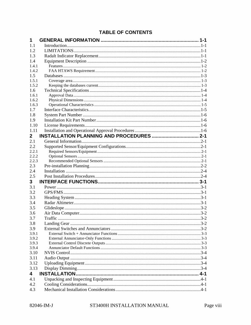
TABLE OF CONTENTS 1 GENERAL INFORMATION ....................................................................... 1-1 1.1 Introduction ...................................................................................................................... 1-1 1.2 LIMITATIONS ................................................................................................................ 1-1 1.3 Radalt Indicator Replacement .......................................................................................... 1-1 1.4 Equipment Description .................................................................................................... 1-2 1.4.1 Features ..................................................................................................................................... 1-2 1.4.2 FAA HTAWS Requirement ...................................................................................................... 1-2 1.5 Databases ......................................................................................................................... 1-3 1.5.1 Coverage area ............................................................................................................................ 1-3 1.5.2 Keeping the databases current ................................................................................................... 1-3 1.6 Technical Specifications .................................................................................................. 1-4 1.6.1 Approval Data ........................................................................................................................... 1-4 1.6.2 Physical Dimensions ................................................................................................................. 1-4 1.6.3 Operational Characteristics ....................................................................................................... 1-5 1.7 Interface Characteristics ................................................................................................... 1-5 1.8 System Part Number ........................................................................................................ 1-6 1.9 Installation Kit Part Number ............................................................................................ 1-6 1.10 License Requirements ...................................................................................................... 1-6 1.11 Installation and Operational Approval Procedures .......................................................... 1-6 2 INSTALLATION PLANNING AND PROCEDURES .................................. 2-1 2.1 General Information ......................................................................................................... 2-1 2.2 Supported Sensor/Equipment Configurations .................................................................. 2-1 2.2.1 Required Sensors/Equipment .................................................................................................... 2-1 2.2.2 Optional Sensors ....................................................................................................................... 2-1 2.2.3 Recommended Optional Sensors .............................................................................................. 2-1 2.3 Pre-installation Planning .................................................................................................. 2-2 2.4 Installation ....................................................................................................................... 2-4 2.5 Post Installation Procedures ............................................................................................. 2-4 3 INTERFACE FUNCTIONS ......................................................................... 3-1 3.1 Power ............................................................................................................................... 3-1 3.2 GPS/FMS ......................................................................................................................... 3-1 3.3 Heading System ............................................................................................................... 3-1 3.4 Radar Altimeter ................................................................................................................ 3-1 3.5 Glideslope ........................................................................................................................ 3-2 3.6 Air Data Computer ........................................................................................................... 3-2 3.7 Traffic .............................................................................................................................. 3-2 3.8 Landing Gear ................................................................................................................... 3-2 3.9 External Switches and Annunciators ............................................................................... 3-2 3.9.1 External Switch + Annunciator Functions ................................................................................ 3-3 3.9.2 External Annunciator-Only Functions ...................................................................................... 3-3 3.9.3 External Control Discrete Outputs ............................................................................................ 3-3 3.9.4 Annunciator Default Functions ................................................................................................. 3-3 3.10 NVIS Control ................................................................................................................... 3-4 3.11 Audio Output ................................................................................................................... 3-4 3.12 Uploading Equipment ...................................................................................................... 3-4 3.13 Display Dimming ............................................................................................................. 3-4 4 INSTALLATION ......................................................................................... 4-1 4.1 Unpacking and Inspecting Equipment ............................................................................. 4-1 4.2 Cooling Considerations .................................................................................................... 4-1 4.3 Mechanical Installation Considerations ........................................................................... 4-1
82046-IM-J ST3400H INSTALLATION MANUAL Page viii
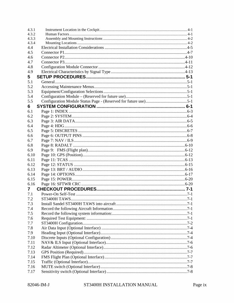
4.3.1 Instrument Location in the Cockpit ........................................................................................... 4-1 4.3.2 Human Factors .......................................................................................................................... 4-1 4.3.3 Assembly and Mounting Instructions ....................................................................................... 4-2 4.3.4 Mounting Locations .................................................................................................................. 4-2 4.4 Electrical Installation Considerations .............................................................................. 4-5 4.5 Connector P1 .................................................................................................................... 4-7 4.6 Connector P2 .................................................................................................................. 4-10 4.7 Connector P3 .................................................................................................................. 4-11 4.8 Configuration Module Connector .................................................................................. 4-12 4.9 Electrical Characteristics by Signal Type ...................................................................... 4-13 5 SETUP PROCEDURES ............................................................................. 5-1 5.1 General ............................................................................................................................. 5-1 5.2 Accessing Maintenance Menus ........................................................................................ 5-1 5.3 Equipment/Configuration Selections ............................................................................... 5-1 5.4 Configuration Module – (Reserved for future use) .......................................................... 5-1 5.5 Configuration Module Status Page - (Reserved for future use) ....................................... 5-1 6 SYSTEM CONFIGURATION ..................................................................... 6-1 6.1 Page 1: INDEX ................................................................................................................ 6-3 6.2 Page 2: SYSTEM ............................................................................................................. 6-4 6.3 Page 3: AIR DATA .......................................................................................................... 6-5 6.4 Page 4: HDG .................................................................................................................... 6-6 6.5 Page 5: DISCRETES ....................................................................................................... 6-7 6.6 Page 6: OUTPUT PINS ................................................................................................... 6-8 6.7 Page 7: NAV / ILS ........................................................................................................... 6-9 6.8 Page 8: RADALT .......................................................................................................... 6-10 6.9 Page 9: FMS (Flight plan) ............................................................................................ 6-12 6.10 Page 10: GPS (Position)................................................................................................. 6-12 6.11 Page 11: TCAS .............................................................................................................. 6-13 6.12 Page 12: STATUS ......................................................................................................... 6-15 6.13 Page 13: BRT / AUDIO ................................................................................................. 6-16 6.14 Page 14: OPTIONS ........................................................................................................ 6-17 6.15 Page 15: POWER ........................................................................................................... 6-20 6.16 Page 16: SFTWR CRC .................................................................................................. 6-20 7 CHECKOUT PROCEDURES..................................................................... 7-1 7.1 Power-On Self-Test ......................................................................................................... 7-1 7.2 ST3400H TAWS .............................................................................................................. 7-1 7.3 Install Sandel ST3400H TAWS into aircraft ................................................................... 7-1 7.4 Record the following Aircraft Information ...................................................................... 7-1 7.5 Record the following system information:....................................................................... 7-1 7.6 Required Test Equipment: ............................................................................................... 7-1 7.7 ST3400H Configuration................................................................................................... 7-2 7.8 Air Data Input (Optional Interface) ................................................................................. 7-4 7.9 Heading Input (Optional Interface) .................................................................................. 7-4 7.10 Discrete Inputs (Optional Configuration) ........................................................................ 7-4 7.11 NAV& ILS Input (Optional Interface)............................................................................. 7-6 7.12 Radar Altimeter (Optional Interface) ............................................................................... 7-6 7.13 GPS Position (Required) .................................................................................................. 7-7 7.14 FMS Flight Plan (Optional Interface) .............................................................................. 7-7 7.15 Traffic (Optional Interface) .............................................................................................. 7-7 7.16 MUTE switch (Optional Interface) .................................................................................. 7-8 7.17 Sensitivity switch (Optional Interface) ............................................................................ 7-8
82046-IM-J ST3400H INSTALLATION MANUAL Page ix
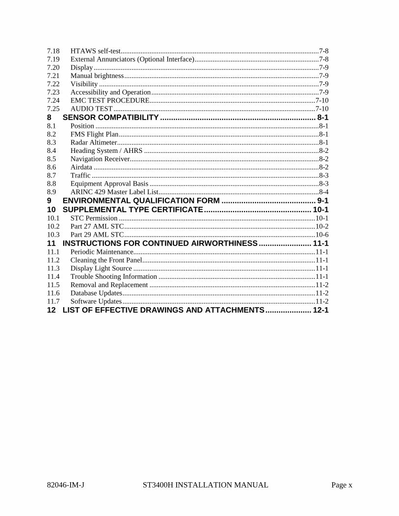
7.18 HTAWS self-test .............................................................................................................. 7-8 7.19 External Annunciators (Optional Interface) ..................................................................... 7-8 7.20 Display ............................................................................................................................. 7-9 7.21 Manual brightness ............................................................................................................ 7-9 7.22 Visibility .......................................................................................................................... 7-9 7.23 Accessibility and Operation ............................................................................................. 7-9 7.24 EMC TEST PROCEDURE............................................................................................ 7-10 7.25 AUDIO TEST ................................................................................................................ 7-10 8 SENSOR COMPATIBILITY ....................................................................... 8-1 8.1 Position ............................................................................................................................ 8-1 8.2 FMS Flight Plan ............................................................................................................... 8-1 8.3 Radar Altimeter ................................................................................................................ 8-1 8.4 Heading System / AHRS ................................................................................................. 8-2 8.5 Navigation Receiver......................................................................................................... 8-2 8.6 Airdata ............................................................................................................................. 8-2 8.7 Traffic .............................................................................................................................. 8-3 8.8 Equipment Approval Basis .............................................................................................. 8-3 8.9 ARINC 429 Master Label List ......................................................................................... 8-4 9 ENVIRONMENTAL QUALIFICATION FORM ........................................... 9-1 10 SUPPLEMENTAL TYPE CERTIFICATE ................................................. 10-1 10.1 STC Permission ............................................................................................................. 10-1 10.2 Part 27 AML STC .......................................................................................................... 10-2 10.3 Part 29 AML STC .......................................................................................................... 10-6 11 INSTRUCTIONS FOR CONTINUED AIRWORTHINESS ........................ 11-1 11.1 Periodic Maintenance..................................................................................................... 11-1 11.2 Cleaning the Front Panel ................................................................................................ 11-1 11.3 Display Light Source ..................................................................................................... 11-1 11.4 Trouble Shooting Information ....................................................................................... 11-1 11.5 Removal and Replacement ............................................................................................ 11-2 11.6 Database Updates ........................................................................................................... 11-2 11.7 Software Updates ........................................................................................................... 11-2 12 LIST OF EFFECTIVE DRAWINGS AND ATTACHMENTS ..................... 12-1
82046-IM-J ST3400H INSTALLATION MANUAL Page x

1 GENERAL INFORMATION
1.1 Introduction
The information contained within this Installation Manual describes the features, functions, technical characteristics, components, approval procedures, installation considerations, setup procedures, checkout procedures and instructions for continued airworthiness for the Sandel Avionics ST3400H Helicopter Terrain Awareness Warning System. For an explanation of the operating controls of the ST3400H, refer to the Pilot’s Guide for the ST3400H, Sandel Avionics P/N 82046-PG.
Sandel Avionics ST3400H HTAWS may be covered by one or more U.S. and foreign patents and pending patent applications, including U.S. Patent Nos. 6,507,288, 6,489,916, and 6,259,378.
1.2 LIMITATIONS
The following stipulation as presented is required by the Federal Aviation Administration for articles approved under Technical Standard Order. This statement does not preclude multiple installation and operational approvals in regard to specific aircraft make, model, or type:
The conditions and tests required for TSO approval of this article are minimum performance standards. Those installing this article, on or in a specific type or class of aircraft, must determine that the aircraft installation conditions are within TSO standards. TSO articles must have separate approval for installation in an aircraft. The article may be installed only according to 14 CFR Part 43 or applicable airworthiness requirements.
Display of DME arcs, Holding Patterns, and Procedure Turns is not currently supported in the ST3400H.
Any installation location is acceptable provided the ST3400H is installed adjacent to the helicopter primary displays, it’s display and annunciations are visible to the pilot, and it’s controls are reachable by the pilot or are suitably remote controlled.
Interconnection of the DC electrical supply to the ST3400H shall be via a non-essential bus for installation in IFR rotorcraft unless replacing an existing instrument already approved on the essential bus.
1.3 Radalt Indicator Replacement
The ST3400H Radalt function is provided to allow the ST3400H to replace an existing Radar Altitude display. Both the current Radar altitude and the selected Minimums alerting altitude are displayed in digital format.
If a Radar altimeter is not installed in the helicopter, the Radar Altitude will not be displayed on the screen. The MINS display will be present and may be used by the pilot as a reference.
82046-IM-J ST3400H INSTALLATION MANUAL Page 1-1

1.4 Equipment Description
The Sandel ST3400H is a self-contained HTAWS (Terrain Awareness Warning System) solution specifically for helicopters that includes an advanced HTAWS computer and an integrated full-color screen built within a standard 3-inch instrument chassis.
The ST3400H uses Sandel’s patented rear-projection display technology. The projector uses a miniature active-matrix LCD display that produces a high-resolution image that is rear-projected directly to the face of the instrument. This technology allows the displayed image to extend to the edges of the instrument’s bezel. The advantage of this edge-to-edge technology is that it eliminates the unusable area surrounding conventional LCD and CRT displays. Even though the Sandel display is in a 3-inch form factor, its image is near the size of a 4” primary display, and can remain directly in the pilot’s field-of-view.
It can be used as a direct replacement for a currently installed Radar altimeter indicator. It includes a MINS setter, MINS discrete output, and a Radalt Test discrete output.
The ST3400H includes built-in warning and caution annunciation. The unit also supports optional external warning or caution annunciation as well as optional collective mounted momentary switches to control certain functions such as alert muting and modes.
The ST3400H may be installed in a single or dual installation.
The ST3400H has an internal recorder that automatically records approximately twenty hours of flight data. This data can be reviewed for content in the event of a system malfunction.
1.4.1 Features
HTAWS is the enhanced terrain warning technology for helicopters that uses GPS position along with databases of terrain and obstacles to reduce or eliminate CFIT accidents. It is similar to the Sandel ST3400 fixed-wing TAWS, with feature enhancements specific to helicopter operations close to the ground.
• Increased vertical accuracy • Separate obstacle database • On-screen obstacle display • 3 arc-second terrain data
The following 5 standard GPWS functional modes (modified for helicopter) are provided for when equipped with supported Radar altimeter and airdata computer:
• ERD (excessive rate of descent) • ALAT (altitude loss after takeoff) • FITNL (flight into terrain when not in landing configuration) • EDGSD (excessive downward glide slope deviation). • 400 feet and below Voice Callouts
1.4.2 FAA HTAWS Requirement
The ST3400H exceeds the FAA requirements for HTAWS alerting, annunciation, and display for installation in Part 27 and Part 29 helicopters
82046-IM-J ST3400H INSTALLATION MANUAL Page 1-2
1.5 Databases
1.5.1 Coverage area
The internal Terrain and Obstacle databases include terrain, charted man-made obstacles, airports, and heliports.
The Terrain and Airport databases are provided by geographical area. The coverage area of the database installed in the ST3400H is shown as part of the sign-on screen after a power cycle.
Remember, there is no guarantee that every obstacle is charted or that every charted obstacle is in the terrain data.
1.5.2 Keeping the databases current
Updates to the databases can be obtained from the Sandel web site and loaded into the equipment using a Windows loader program and a laptop computer. This is done through a high-speed USB port located on the front right corner. Loading instructions are supplied along with the applicable database.
The databases can be updated during normal maintenance to the helicopter.
82046-IM-J ST3400H INSTALLATION MANUAL Page 1-3
1.6 Technical Specifications
The following section describes the technical characteristics, which include the appliance approval basis, physical and electrical properties, electrical connector pin allocation which details function and gradient or equipment protocol, and ARINC label support. Also included is the description of the ST3400H installation components, other equipment and installation requirements. A review of the installation approval procedures is provided for filing with authorities.
1.6.1 Approval Data
Technical Standard Orders (TSO and ETSO):
TSO-C87 / ETSO-2C87 Airborne Low-Range Radio Altimeter (Incomplete – ST3400H provides display only) TSO-C113 / ETSO-C113 Airborne Multipurpose Electronic Display TSO-C118 / ETSO-C118 Traffic Alert and Collision Avoidance System (TCAS-I) (Incomplete – ST3400H provides display only) TSO-C194 / ETSO-C194 Helicopter Terrain Awareness and Warning System (HTAWS)
Software Certification: DO-178B Level C Environmental: DO-160F
Databases: DO-200A
1.6.2 Physical Dimensions
The ST3400H is enclosed in an ARINC 408, 3ATI form factor enclosure and is mounted to an instrument panel.
Form Factor: 3ATI (ARINC 408) Width: 3.175 inches Height: 3.175 inches Length: 9.5 inches Weight: 2.77 pounds with configuration module. (Cable weight not
included) Mounting: 3 ATI Clamp
Display: 200dpi
82046-IM-J ST3400H INSTALLATION MANUAL Page 1-4
1.6.3 Operational Characteristics
Temperature/Altitude: -20° C to +70° C / up to 55,000 F Power Input: 28VDC nominal, 40 watt maximum. Operating range
22VDC – 33VDC Cooling Requirements: Internal fan. Requires ambient air at fan input along the four
corners of the 3ATI case.
1.7 Interface Characteristics
The ST3400H is software configurable and configuration data is stored internally and in an optional airframe-resident configuration module.
Configuration Module: Rear mounted inside 9-pin ‘D’ connector shell Data Loading: Front panel USB GPS Position: ARINC 429 or RS232
GPS Flight plan: ARINC 429 or RS232 Air Data: ARINC 429 or Analog Heading: ARINC 429 or ARINC 407 (XYZ)
Gear: Discrete: active high or low Glideslope: ARINC 429 or low-level deviation and flag
Localizer: ARINC 429 or low-level deviation and flag Audio Outputs: 4 to 8 ohm speaker, 5 watt max
500 ohm, 25mw or 125mw configurable via strap External Annunciators: Open/GND (Open Drain) GND=Active
250ma maximum (installation optional) External Switches: Momentary action, Open/GND
GND to activate (installation optional) Radar Altimeter: ARINC 429 or Analog
Traffic: ARINC 429
82046-IM-J ST3400H INSTALLATION MANUAL Page 1-5
1.8 System Part Number
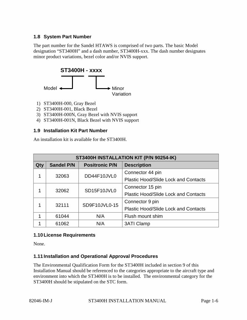
The part number for the Sandel HTAWS is comprised of two parts. The basic Model designation “ST3400H” and a dash number, ST3400H-xxx. The dash number designates minor product variations, bezel color and/or NVIS support.
1) ST3400H-000, Gray Bezel 2) ST3400H-001, Black Bezel 3) ST3400H-000N, Gray Bezel with NVIS support 4) ST3400H-001N, Black Bezel with NVIS support
1.9 Installation Kit Part Number
An installation kit is available for the ST3400H.
ST3400H INSTALLATION KIT (P/N 90254-IK) Qty Sandel P/N Positronic P/N Description
1 32063 DD44F10JVL0 Connector 44 pin Plastic Hood/Slide Lock and Contacts
1 32062 SD15F10JVL0 Connector 15 pin Plastic Hood/Slide Lock and Contacts
1 32111 SD9F10JVL0-15 Connector 9 pin Plastic Hood/Slide Lock and Contacts
1 61044 N/A Flush mount shim 1 61062 N/A 3ATI Clamp
1.10 License Requirements
None.
1.11 Installation and Operational Approval Procedures
The Environmental Qualification Form for the ST3400H included in section 9 of this Installation Manual should be referenced to the categories appropriate to the aircraft type and environment into which the ST3400H is to be installed. The environmental category for the ST3400H should be stipulated on the STC form.
ST3400H - xxxx
Model Minor Variation
82046-IM-J ST3400H INSTALLATION MANUAL Page 1-6

A “Functional Ground Test Procedures/Report” included in section 7 of this manual should be used as a basis for validating the ST3400H equipment configuration and to verify proper installation and functional performance. A permanent copy of the STC form must be filed and maintained by the installing agency. Another copy must be presented to the aircraft owner for entry into the aircraft maintenance records, as well as a copy forwarded to Sandel Avionics along with the Warranty Registration Form, to be filed after completion and installation acceptance.
If any difficulty is experienced with the functionality or operational performance of the ST3400H, contact Sandel for assistance.
82046-IM-J ST3400H INSTALLATION MANUAL Page 1-7
2 INSTALLATION PLANNING AND PROCEDURES The ST3400H has been designed to ensure maximum interoperability with external avionics. Contact Sandel with any questions about interfacing to specific avionics equipment not covered in the installation drawings in this manual.
2.1 General Information
To simplify installation, after signals are wired to the ST3400H pins, on-screen setups are used in a post-installation procedure. Maintenance menu pages provide a function selection capability. For most equipment, selections are made by equipment make and model.
Refer to the installation schematics section 12 of this manual, for details on connecting required components.
2.2 Supported Sensor/Equipment Configurations
2.2.1 Required Sensors/Equipment
• GPS position • Gear (only if the helicopter has retractable gear). • Audio system with available unswitched input.
2.2.2 Optional Sensors
• Heading Display: Provides no-track terrain display • GPS Flight plan Display: displays flight plan line • Radar Altitude GPWS: Provides callouts; • Airdata GPWS: improves accuracy of certain modes • LOC/GS GPWS: adds Glideslope alert
2.2.3 Recommended Optional Sensors
A Heading Sensor is highly recommended; without a heading system no terrain will be presented on the display during hover operations or on-ground. When in maintenance mode, with no heading system and track invalid, unit displays North Up.
Radar Altitude is highly recommended. This not only supplies numerous GPWS alerts, but provides altitude callouts which provide an additional safety benefit.
82046-IM-J ST3400H INSTALLATION MANUAL Page 2-1
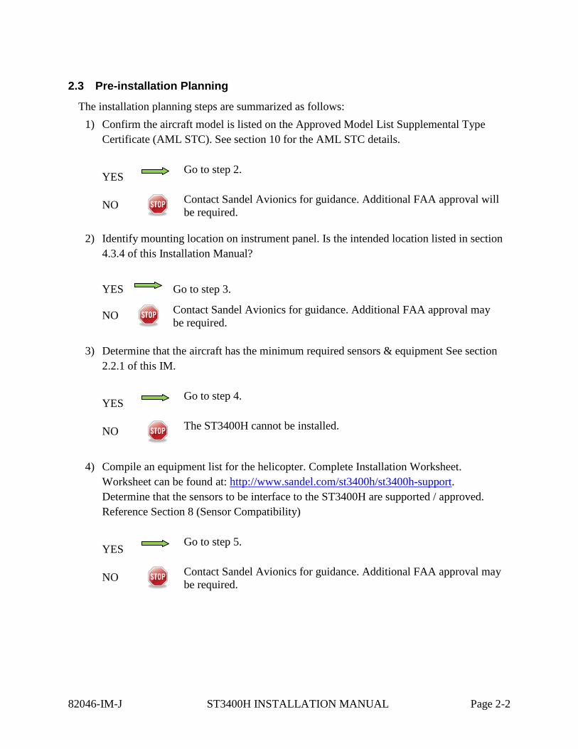
2.3 Pre-installation Planning
The installation planning steps are summarized as follows: 1) Confirm the aircraft model is listed on the Approved Model List Supplemental Type
Certificate (AML STC). See section 10 for the AML STC details.
YES Go to step 2.
NO
Contact Sandel Avionics for guidance. Additional FAA approval will be required.
2) Identify mounting location on instrument panel. Is the intended location listed in section
4.3.4 of this Installation Manual?
YES Go to step 3.
NO
Contact Sandel Avionics for guidance. Additional FAA approval may be required.
3) Determine that the aircraft has the minimum required sensors & equipment See section
2.2.1 of this IM.
YES Go to step 4.
NO
The ST3400H cannot be installed.
4) Compile an equipment list for the helicopter. Complete Installation Worksheet.
Worksheet can be found at: http://www.sandel.com/st3400h/st3400h-support. Determine that the sensors to be interface to the ST3400H are supported / approved. Reference Section 8 (Sensor Compatibility)
YES Go to step 5.
NO
Contact Sandel Avionics for guidance. Additional FAA approval may be required.
82046-IM-J ST3400H INSTALLATION MANUAL Page 2-2
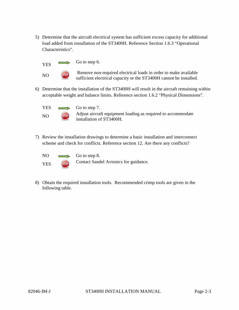
5) Determine that the aircraft electrical system has sufficient excess capacity for additional
load added from installation of the ST3400H. Reference Section 1.6.3 “Operational Characteristics”.
YES Go to step 6.
NO Remove non-required electrical loads in order to make available sufficient electrical capacity or the ST3400H cannot be installed.
6) Determine that the installation of the ST3400H will result in the aircraft remaining within
acceptable weight and balance limits. Reference section 1.6.2 “Physical Dimensions”. YES Go to step 7.
NO
Adjust aircraft equipment loading as required to accommodate installation of ST3400H.
7) Review the installation drawings to determine a basic installation and interconnect scheme and check for conflicts. Reference section 12. Are there any conflicts? NO Go to step 8.
YES
Contact Sandel Avionics for guidance.
8) Obtain the required installation tools. Recommended crimp tools are given in the following table.
82046-IM-J ST3400H INSTALLATION MANUAL Page 2-3
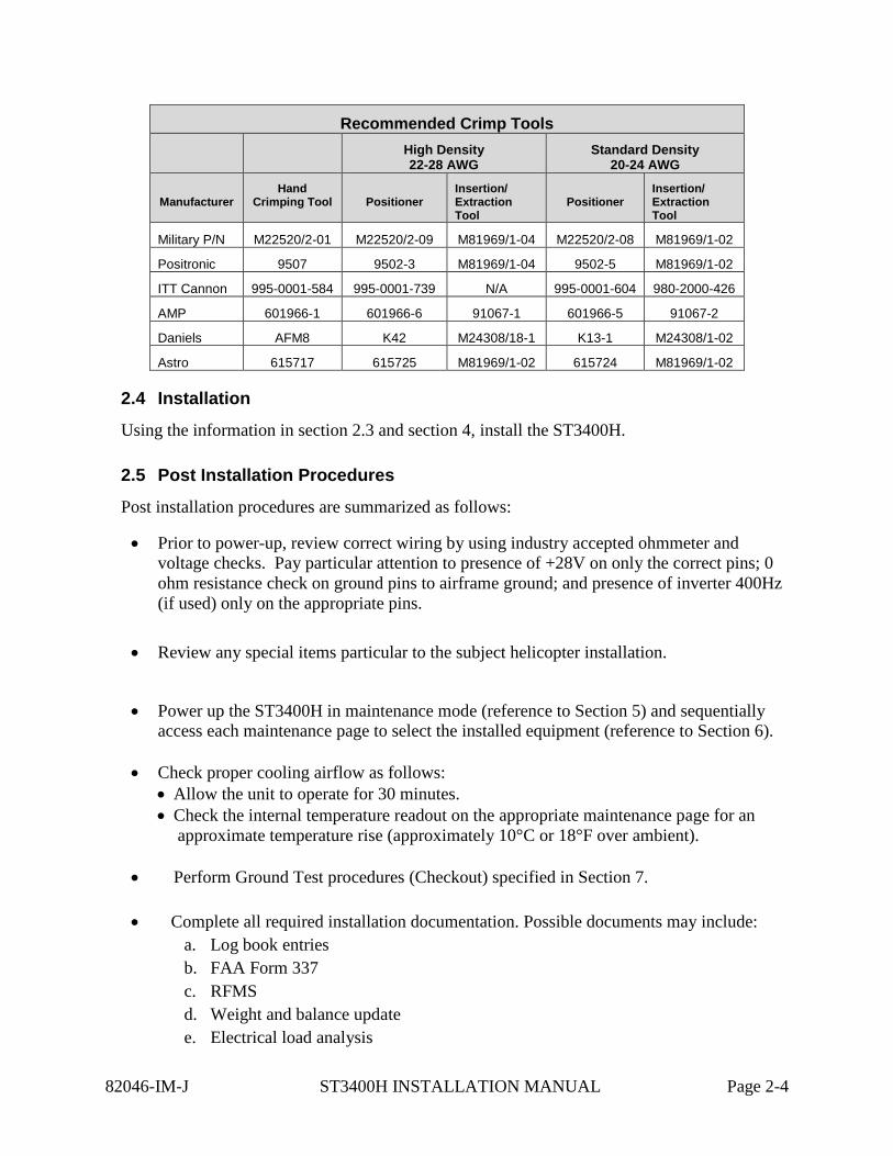
Recommended Crimp Tools High Density
22-28 AWG Standard Density
20-24 AWG
Manufacturer Hand
Crimping Tool
Positioner Insertion/ Extraction Tool
Positioner
Insertion/ Extraction Tool
Military P/N M22520/2-01 M22520/2-09 M81969/1-04 M22520/2-08 M81969/1-02
Positronic 9507 9502-3 M81969/1-04 9502-5 M81969/1-02
ITT Cannon 995-0001-584 995-0001-739 N/A 995-0001-604 980-2000-426
AMP 601966-1 601966-6 91067-1 601966-5 91067-2
Daniels AFM8 K42 M24308/18-1 K13-1 M24308/1-02
Astro 615717 615725 M81969/1-02 615724 M81969/1-02
2.4 Installation
Using the information in section 2.3 and section 4, install the ST3400H.
2.5 Post Installation Procedures
Post installation procedures are summarized as follows:
• Prior to power-up, review correct wiring by using industry accepted ohmmeter and voltage checks. Pay particular attention to presence of +28V on only the correct pins; 0 ohm resistance check on ground pins to airframe ground; and presence of inverter 400Hz (if used) only on the appropriate pins.
• Review any special items particular to the subject helicopter installation.
• Power up the ST3400H in maintenance mode (reference to Section 5) and sequentially access each maintenance page to select the installed equipment (reference to Section 6).
• Check proper cooling airflow as follows:
• Allow the unit to operate for 30 minutes. • Check the internal temperature readout on the appropriate maintenance page for an
approximate temperature rise (approximately 10°C or 18°F over ambient). • Perform Ground Test procedures (Checkout) specified in Section 7.
• Complete all required installation documentation. Possible documents may include:
a. Log book entries b. FAA Form 337 c. RFMS d. Weight and balance update e. Electrical load analysis
82046-IM-J ST3400H INSTALLATION MANUAL Page 2-4
• For Continued Airworthiness information refer to Instructions for Continued Airworthiness in Section 11.
82046-IM-J ST3400H INSTALLATION MANUAL Page 2-5
3 INTERFACE FUNCTIONS
3.1 Power
The primary power is 28 volt dc on J-2 and is supplied from the aircraft avionics buss through a circuit breaker. Ground is provided on J-2 and should be attached to an approved airframe ground.
A 26 volt 400Hz excitation input is available at J-16. It is only used in the case of an XYZ heading source. If the installation of the ST3400 does not use an XYZ (ARINC407) signal source, the inverter input is not required and should be grounded.
3.2 GPS/FMS
A GPS position input is required. The port is configurable in the Maintenance Menu pages for High or Low speed ARINC and RS232. A list of supported labels is listed in section 8.8 .
A separate GPS flight plan input is normally connected but is optional.
In the case where all information is coming from the same 429 source, the single receiver is fed to both inputs.
Note: In the case of the Garmin GNS series, the position input is connected to the receiver’s RS232 output, and the Flight plan data is connected to the receiver’s GAMA ARINC 429 output.
3.3 Heading System A Heading input is not required. However, without a heading system the terrain display will be removed at low groundspeeds. When the heading input is present the terrain display remains on the screen even during hover operations. It is highly recommended.
When in maintenance mode, with no heading system and track invalid, unit displays North Up.
3.4 Radar Altimeter
The ST3400H has provisions for a Radar Altimeter input. Radar Altimeter input may be from an ARINC 429 or DC analog sources. The Radar Altimeter input is used to obtain height above terrain for GPWS alerting and for altitude callouts.
The Radar altimeter always produces a single ‘300’ or ‘100’ mandatory audio callout, depending on NORM/LOW sensitivity selected by the pilot. When in HIGH-SENS, a ‘400’ mandatory audio callout will be produced. Optionally the installer may enable any or all of the following additional audio callouts:
300’, 200’, 100’, 50’, 40’, 30’, 20’, 10’
These callouts are a great safety feature and their use is encouraged.
82046-IM-J ST3400H INSTALLATION MANUAL Page 3-1

When the Radalt is lower than the MINS setting a MINS discrete output is activated and an audio callout “MINIMUMS” occurs.
When the Radar Altimeter is not configured, the MINS setting is retained on the display for use as a visual reference by the pilot. The MINS discrete and callout will be disabled.
The MINS setting knob on the front panel has a push button function. This operates the momentary discrete on J3, RADALT TEST.
3.5 Glideslope
This input provides the GPWS mode-5 glideslope alert. ARINC 429 or low level analog inputs for Glideslope deviation, Glideslope flag status, and Localizer and Localizer Flag are provided.
An additional discrete input is available for Back Course from the HSI, which acts to disable Glideslope alerting while on a Back Course approach.
3.6 Air Data Computer
Airdata input is recommended. ARINC 429 airdata is supported as well as analog pressure altitude. Use of analog pressure altitude requires ST3400H with MOD-1 installed per SIL 3400H-01.
3.7 Traffic
The ST3400H supports Traffic input via single ARINC 429 input. Traffic data is overlaid on terrain.
Some traffic processors require remote switches. See Traffic interface drawings in this manual for these requirements.
3.8 Landing Gear
The ST3400 has provisions on J-1 for Gear Down input discrete to indicate that the gear is in the “DOWN” position for helicopters equipped with retractable landing gear.
The configuration is performed in the Maintenance Menu pages given in the Setup Procedures section of this manual. If the system is installed in a helicopter without retractable landing gear, select “NONE” on maintenance page configuration item.
3.9 External Switches and Annunciators
All external switches and annunciators are optional.
External switches are momentary contact OPEN/GND, normally open.
External annunciators, if used, must be properly labeled and colored.
82046-IM-J ST3400H INSTALLATION MANUAL Page 3-2
Discrete outputs are OPEN/GND and capable of sinking a maximum of 250milliamps to ground when active. They can drive incandescent lamps and/or relays. Dimming of external annunciators is accomplished by sourcing the annunciators from the helicopter day/night bus.
3.9.1 External Switch + Annunciator Functions
These switch/annunciator functions are on J2. The external switches perform the same functions as their related front panel switches.
• GS Inh • Mute Momentary press mutes an active Caution • Mute Press and hold invokes TAWS INH function • Sensitivity Momentary press toggles sensitivity selections. • Sensitivity Press and hold invokes OFF-APT mode
3.9.2 External Annunciator-Only Functions
These annunciator discrete outputs are available on J2:
• Caution Alert • Warning Alert • Taws Inhibit
3.9.3 External Control Discrete Outputs
These control outputs are available:
• Radalt Test • TCAS Inhibit
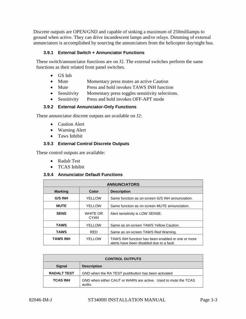
3.9.4 Annunciator Default Functions
ANNUNCIATORS Marking Color Description
G/S INH YELLOW Same function as on-screen G/S INH annunciation.
MUTE YELLOW Same function as on-screen MUTE annunciation.
SENS WHITE OR CYAN
Alert sensitivity is LOW SENSE.
TAWS YELLOW Same as on-screen TAWS Yellow Caution.
TAWS RED Same as on-screen TAWS Red Warning.
TAWS INH YELLOW TAWS INH function has been enabled or one or more alerts have been disabled due to a fault.
CONTROL OUTPUTS
Signal Description
RADALT TEST GND when the RA TEST pushbutton has been activated
TCAS INH GND when either CAUT or WARN are active. Used to mute the TCAS audio.
82046-IM-J ST3400H INSTALLATION MANUAL Page 3-3
3.10 NVIS Control
The NVIS CTRL discrete is an OPEN/GND input which controls the NVIS mode and is intended to be connected to a sustained toggle or sustained pushbutton switch. In the default configuration GND=NVIS ON and OPEN=NVIS OFF. In this configuration a wire break to the switch would result in NVIS OFF.
The input configuration can be changed by the installer in the SYSTEM maintenance page to reverse the logic so that GND=NVIS OFF and OPEN=NVIS ON. In this configuration a wire break to the switch would result in NVIS ON.
3.11 Audio Output
The audio output produces all advisories and alerts which utilize audio.
Two types of outputs are provided, a speaker output and headphone output. The outputs are located on J3 and connection to at least one of these outputs is required.
The headphone output, if used, must connect to the un-switched input of the helicopter audio system. This output is selectable to a nominal level of 25mw or 150mw output by strapping jumpers on J3. If no jumper is installed the headphone output is disabled.
The speaker output, if used, must be directly connected to a dedicated 4 or 8 ohm cockpit speaker.
A volume level trim adjustment which affects both outputs simultaneously is present on the AUDIO maintenance page.
3.12 Uploading Equipment
A USB interface is available on the front of the ST3400H to upload system software, terrain data, obstacle data, airport data, and configuration data into memory and to download configuration data from memory.
Data is loaded from a PC or laptop computer with Microsoft Windows XP (or later) operating system software to the ST3400H. Drivers, the loader program, and loading instructions are supplied with the applicable software or data.
3.13 Display Dimming
The ST3400H screen dimmer is controlled from the front panel knob using the PULL position.
External annunciator dimming may be accomplished using the existing aircraft day/night buss by connecting the high-side of the annunciator lamps day/night buss.
82046-IM-J ST3400H INSTALLATION MANUAL Page 3-4
4 INSTALLATION The ST3400H should be installed in accordance with standards established by the customer’s installing agency, and existing conditions as to unit location and type of installation.
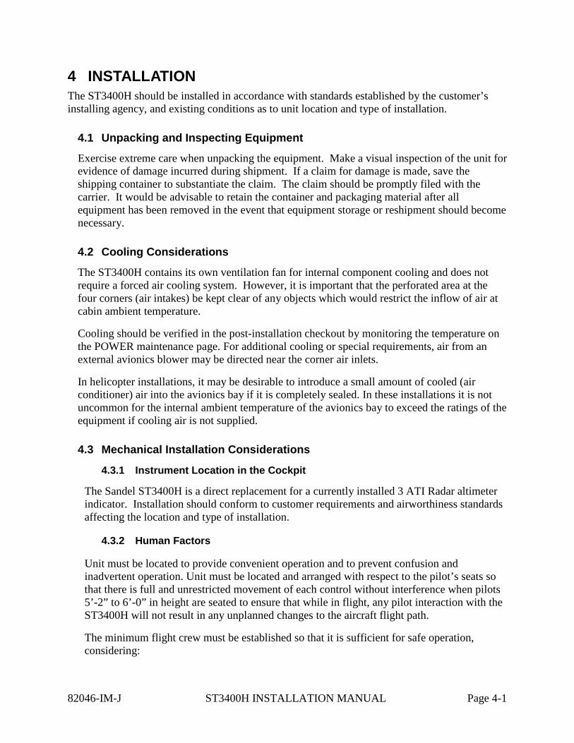
4.1 Unpacking and Inspecting Equipment
Exercise extreme care when unpacking the equipment. Make a visual inspection of the unit for evidence of damage incurred during shipment. If a claim for damage is made, save the shipping container to substantiate the claim. The claim should be promptly filed with the carrier. It would be advisable to retain the container and packaging material after all equipment has been removed in the event that equipment storage or reshipment should become necessary.
4.2 Cooling Considerations
The ST3400H contains its own ventilation fan for internal component cooling and does not require a forced air cooling system. However, it is important that the perforated area at the four corners (air intakes) be kept clear of any objects which would restrict the inflow of air at cabin ambient temperature.
Cooling should be verified in the post-installation checkout by monitoring the temperature on the POWER maintenance page. For additional cooling or special requirements, air from an external avionics blower may be directed near the corner air inlets.
In helicopter installations, it may be desirable to introduce a small amount of cooled (air conditioner) air into the avionics bay if it is completely sealed. In these installations it is not uncommon for the internal ambient temperature of the avionics bay to exceed the ratings of the equipment if cooling air is not supplied.
4.3 Mechanical Installation Considerations
4.3.1 Instrument Location in the Cockpit
The Sandel ST3400H is a direct replacement for a currently installed 3 ATI Radar altimeter indicator. Installation should conform to customer requirements and airworthiness standards affecting the location and type of installation.
4.3.2 Human Factors
Unit must be located to provide convenient operation and to prevent confusion and inadvertent operation. Unit must be located and arranged with respect to the pilot’s seats so that there is full and unrestricted movement of each control without interference when pilots 5’-2” to 6’-0” in height are seated to ensure that while in flight, any pilot interaction with the ST3400H will not result in any unplanned changes to the aircraft flight path.
The minimum flight crew must be established so that it is sufficient for safe operation, considering:
82046-IM-J ST3400H INSTALLATION MANUAL Page 4-1
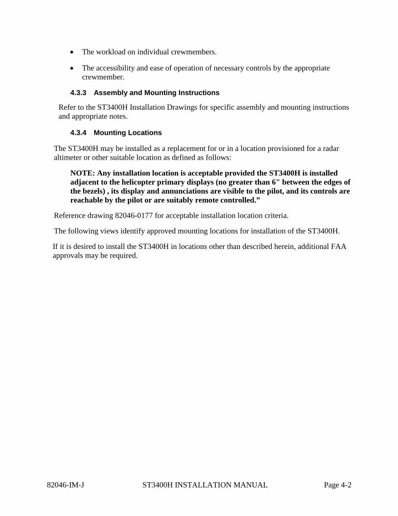
• The workload on individual crewmembers.
• The accessibility and ease of operation of necessary controls by the appropriate crewmember.
4.3.3 Assembly and Mounting Instructions
Refer to the ST3400H Installation Drawings for specific assembly and mounting instructions and appropriate notes.
4.3.4 Mounting Locations
The ST3400H may be installed as a replacement for or in a location provisioned for a radar altimeter or other suitable location as defined as follows:
NOTE: Any installation location is acceptable provided the ST3400H is installed adjacent to the helicopter primary displays (no greater than 6" between the edges of the bezels) , its display and annunciations are visible to the pilot, and its controls are reachable by the pilot or are suitably remote controlled.”
Reference drawing 82046-0177 for acceptable installation location criteria.
The following views identify approved mounting locations for installation of the ST3400H.
If it is desired to install the ST3400H in locations other than described herein, additional FAA approvals may be required.
82046-IM-J ST3400H INSTALLATION MANUAL Page 4-2
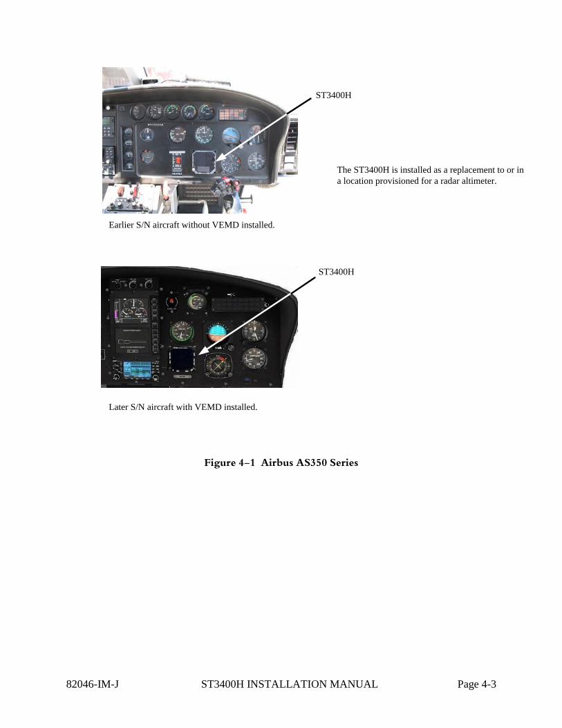
Earlier S/N aircraft without VEMD installed.
Later S/N aircraft with VEMD installed.
The ST3400H is installed as a replacement to or in a location provisioned for a radar altimeter.
ST3400H
ST3400H
Figure 4-1 Airbus AS350 Series
82046-IM-J ST3400H INSTALLATION MANUAL Page 4-3
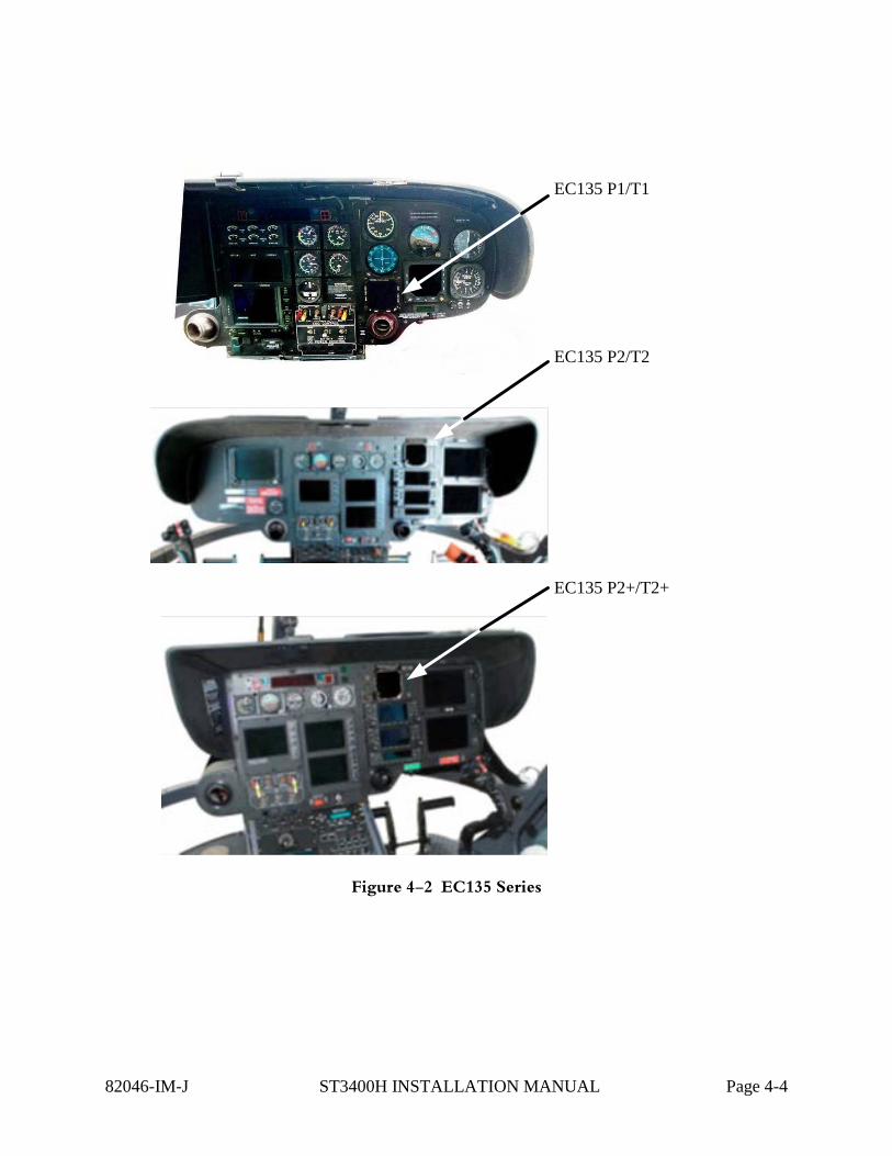
EC135 P1/T1
EC135 P2/T2
EC135 P2+/T2+
Figure 4-2 EC135 Series
82046-IM-J ST3400H INSTALLATION MANUAL Page 4-4
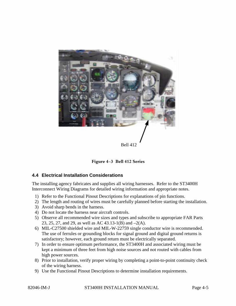
Bell 412
Figure 4-3 Bell 412 Series
4.4 Electrical Installation Considerations
The installing agency fabricates and supplies all wiring harnesses. Refer to the ST3400H Interconnect Wiring Diagrams for detailed wiring information and appropriate notes.
1) Refer to the Functional Pinout Descriptions for explanations of pin functions. 2) The length and routing of wires must be carefully planned before starting the installation. 3) Avoid sharp bends in the harness. 4) Do not locate the harness near aircraft controls. 5) Observe all recommended wire sizes and types and subscribe to appropriate FAR Parts
23, 25, 27, and 29, as well as AC 43.13-1(B) and –2(A). 6) MIL-C27500 shielded wire and MIL-W-22759 single conductor wire is recommended.
The use of ferrules or grounding blocks for signal ground and digital ground returns is satisfactory; however, each ground return must be electrically separated.
7) In order to ensure optimum performance, the ST3400H and associated wiring must be kept a minimum of three feet from high noise sources and not routed with cables from high power sources.
8) Prior to installation, verify proper wiring by completing a point-to-point continuity check of the wiring harness.
9) Use the Functional Pinout Descriptions to determine installation requirements.
82046-IM-J ST3400H INSTALLATION MANUAL Page 4-5

Ground Bonding. Bonding of the ST3400H shall be in accordance with AC 43.13-1B, Chapter 11, Section 15. After installation, bonding shall be measured and the result shall be 10 milliohms or less between the ST3400H case and the instrument panel.
Power Wiring. To assure that the ST3400H will operate properly down to its rated minimum input voltage, ensure that two power wires of at least the recommended size are connected in accordance with the installation drawings.
82046-IM-J ST3400H INSTALLATION MANUAL Page 4-6
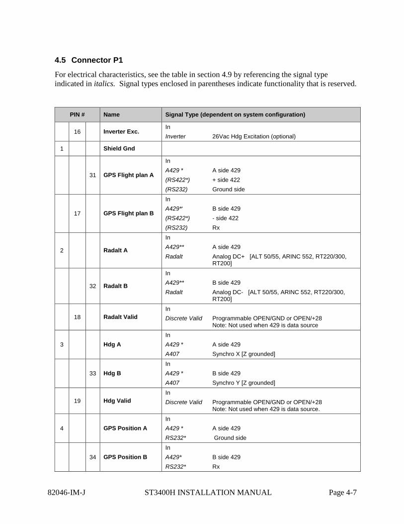
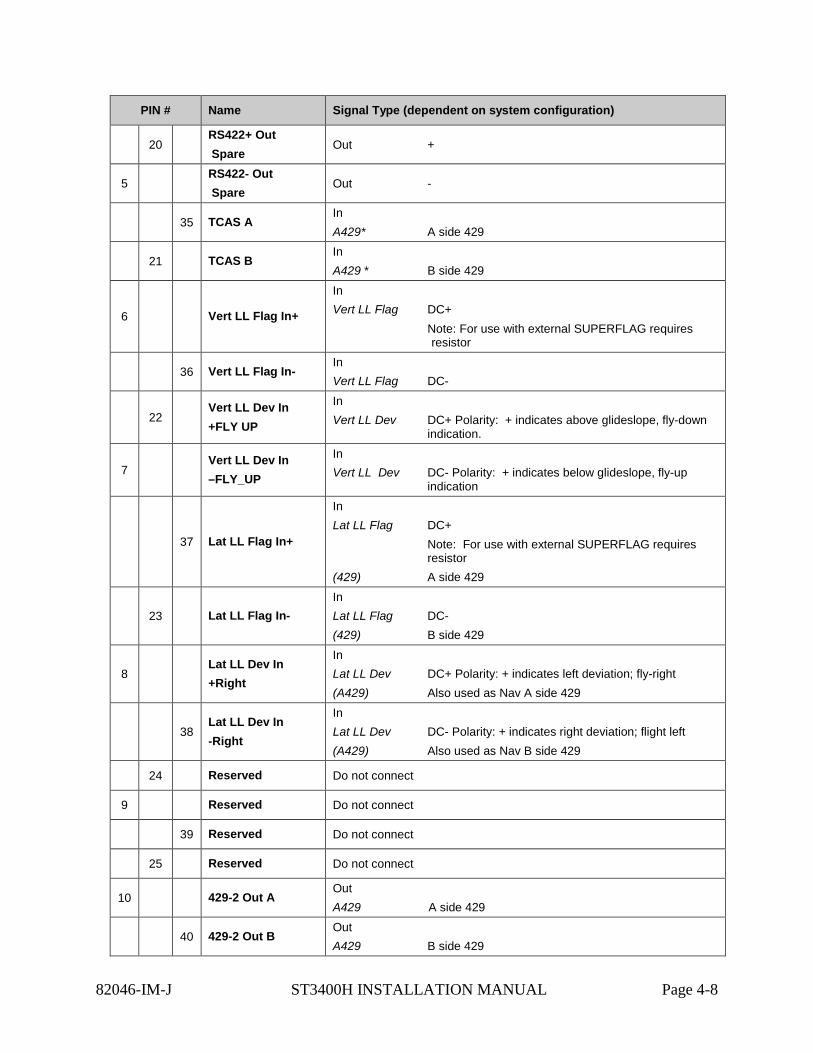
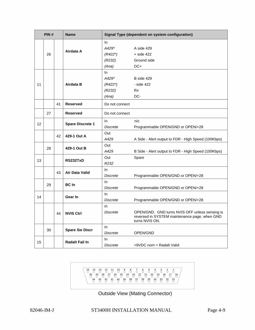
4.5 Connector P1
For electrical characteristics, see the table in section 4.9 by referencing the signal type indicated in italics. Signal types enclosed in parentheses indicate functionality that is reserved.
PIN # Name Signal Type (dependent on system configuration)
16 Inverter Exc. In Inverter 26Vac Hdg Excitation (optional)
1 Shield Gnd
31 GPS Flight plan A
In A429 * A side 429 (RS422*) + side 422 (RS232) Ground side
17 GPS Flight plan B
In A429*‘ B side 429 (RS422*) - side 422 (RS232) Rx
2 Radalt A
In A429** A side 429 Radalt Analog DC+ [ALT 50/55, ARINC 552, RT220/300,
RT200]
32 Radalt B
In A429** B side 429 Radalt Analog DC- [ALT 50/55, ARINC 552, RT220/300,
RT200]
18 Radalt Valid In Discrete Valid Programmable OPEN/GND or OPEN/+28
Note: Not used when 429 is data source
3 Hdg A In A429 * A side 429 A407 Synchro X [Z grounded]
33 Hdg B In A429 * B side 429 A407 Synchro Y [Z grounded]
19 Hdg Valid In Discrete Valid Programmable OPEN/GND or OPEN/+28
Note: Not used when 429 is data source.
4 GPS Position A In A429 * A side 429 RS232* Ground side
34 GPS Position B In A429* B side 429 RS232* Rx
82046-IM-J ST3400H INSTALLATION MANUAL Page 4-7
PIN # Name Signal Type (dependent on system configuration)
20 RS422+ Out Spare
Out +
5 RS422- Out Spare
Out -
35 TCAS A In A429* A side 429
21 TCAS B In A429 * B side 429
6 Vert LL Flag In+
In Vert LL Flag DC+ Note: For use with external SUPERFLAG requires
resistor
36 Vert LL Flag In- In Vert LL Flag DC-
22 Vert LL Dev In +FLY UP
In Vert LL Dev DC+ Polarity: + indicates above glideslope, fly-down
indication.
7 Vert LL Dev In –FLY_UP
In Vert LL Dev DC- Polarity: + indicates below glideslope, fly-up
indication
37 Lat LL Flag In+
In Lat LL Flag DC+ Note: For use with external SUPERFLAG requires
resistor (429) A side 429
23 Lat LL Flag In- In Lat LL Flag DC- (429) B side 429
8 Lat LL Dev In +Right
In Lat LL Dev DC+ Polarity: + indicates left deviation; fly-right (A429) Also used as Nav A side 429
38 Lat LL Dev In -Right
In Lat LL Dev DC- Polarity: + indicates right deviation; flight left (A429) Also used as Nav B side 429
24 Reserved Do not connect
9 Reserved Do not connect
39 Reserved Do not connect
25 Reserved Do not connect
10 429-2 Out A Out A429 A side 429
40 429-2 Out B Out A429 B side 429
82046-IM-J ST3400H INSTALLATION MANUAL Page 4-8
PIN # Name Signal Type (dependent on system configuration)
26 Airdata A
In A429* A side 429 (R422*) + side 422 (R232) Ground side (Ana) DC+
11 Airdata B
In A429* B side 429 (R422*) - side 422 (R232) Rx (Ana) DC-
41 Reserved Do not connect
27 Reserved Do not connect
12 Spare Discrete 1 In n/c Discrete Programmable OPEN/GND or OPEN/+28
42 429-1 Out A Out A429 A Side - Alert output to FDR - High Speed (100Kbps)
28 429-1 Out B Out A429 B Side - Alert output to FDR - High Speed (100Kbps)
13 RS232TxD Out Spare R232
43 Air Data Valid In Discrete Programmable OPEN/GND or OPEN/+28
29 BC In In Discrete Programmable OPEN/GND or OPEN/+28
14 Gear In In Discrete Programmable OPEN/GND or OPEN/+28
44 NVIS Ctrl
In Discrete OPEN/GND. GND turns NVIS OFF unless sensing is
reversed in SYSTEM maintenance page, when GND turns NVIS ON.
30 Spare Sw Discr In Discrete OPEN/GND
15 Radalt Fail In In Discrete >9VDC nom = Radalt Valid
Outside View (Mating Connector)
15
30
44
14
29
43
13
28
42
12
27
41
11
26
40
10
25
39
9
24
38
8
23
37
7
22
36
1
16
6
21
35
5
20
34
4
19
33
3
18
32
2
17
31
82046-IM-J ST3400H INSTALLATION MANUAL Page 4-9
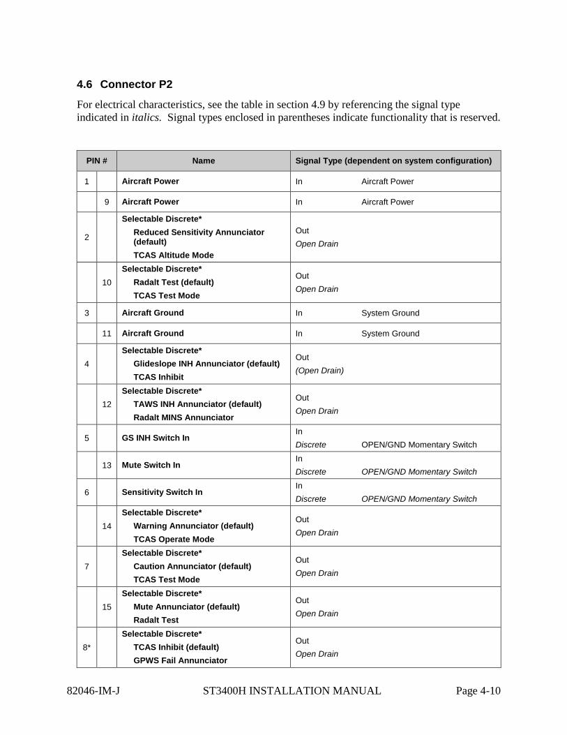
4.6 Connector P2
For electrical characteristics, see the table in section 4.9 by referencing the signal type indicated in italics. Signal types enclosed in parentheses indicate functionality that is reserved.
PIN # Name Signal Type (dependent on system configuration)
1 Aircraft Power In Aircraft Power
9 Aircraft Power In Aircraft Power
2
Selectable Discrete* Reduced Sensitivity Annunciator (default) TCAS Altitude Mode
Out Open Drain
10 Selectable Discrete*
Radalt Test (default) TCAS Test Mode
Out Open Drain
3 Aircraft Ground In System Ground
11 Aircraft Ground In System Ground
4 Selectable Discrete*
Glideslope INH Annunciator (default) TCAS Inhibit
Out (Open Drain)
12 Selectable Discrete*
TAWS INH Annunciator (default) Radalt MINS Annunciator
Out Open Drain
5 GS INH Switch In In Discrete OPEN/GND Momentary Switch
13 Mute Switch In In Discrete OPEN/GND Momentary Switch
6 Sensitivity Switch In In Discrete OPEN/GND Momentary Switch
14 Selectable Discrete*
Warning Annunciator (default) TCAS Operate Mode
Out Open Drain
7 Selectable Discrete*
Caution Annunciator (default) TCAS Test Mode
Out Open Drain
15 Selectable Discrete*
Mute Annunciator (default) Radalt Test
Out Open Drain
8* Selectable Discrete*
TCAS Inhibit (default) GPWS Fail Annunciator
Out Open Drain
82046-IM-J ST3400H INSTALLATION MANUAL Page 4-10
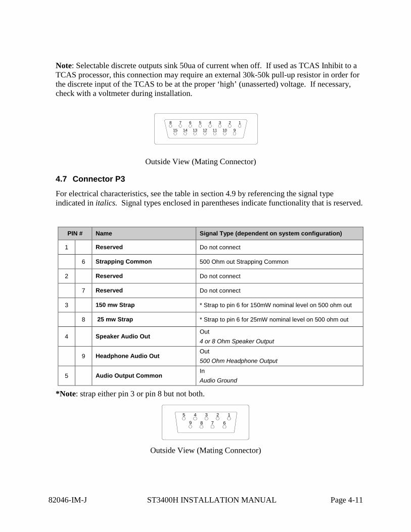
Note: Selectable discrete outputs sink 50ua of current when off. If used as TCAS Inhibit to a TCAS processor, this connection may require an external 30k-50k pull-up resistor in order for the discrete input of the TCAS to be at the proper ‘high’ (unasserted) voltage. If necessary, check with a voltmeter during installation.
Outside View (Mating Connector)
4.7 Connector P3
For electrical characteristics, see the table in section 4.9 by referencing the signal type indicated in italics. Signal types enclosed in parentheses indicate functionality that is reserved.
PIN # Name Signal Type (dependent on system configuration)
1 Reserved Do not connect
6 Strapping Common 500 Ohm out Strapping Common
2 Reserved Do not connect
7 Reserved Do not connect
3 150 mw Strap * Strap to pin 6 for 150mW nominal level on 500 ohm out
8 25 mw Strap * Strap to pin 6 for 25mW nominal level on 500 ohm out
4 Speaker Audio Out Out 4 or 8 Ohm Speaker Output
9 Headphone Audio Out Out 500 Ohm Headphone Output
5 Audio Output Common In Audio Ground
*Note: strap either pin 3 or pin 8 but not both.
Outside View (Mating Connector)
8
15
7
14
16
13
5
12
4
11
3
10
2
9
8 7
1
6
5 4 3 2
9
82046-IM-J ST3400H INSTALLATION MANUAL Page 4-11

4.8 Configuration Module Connector
Accepts ST3400H Configuration Module.
The configuration module holds all installation data and is specific to the aircraft. If the ST3400H is swapped, re-using the configuration module will automatically reconfigure the new unit to the original aircraft configuration.
The ST3400 will may be operated with or without a configuration module connected. If no configuration module is present the ST3400H will operate but the pilot will receive an advisory message.
82046-IM-J ST3400H INSTALLATION MANUAL Page 4-12
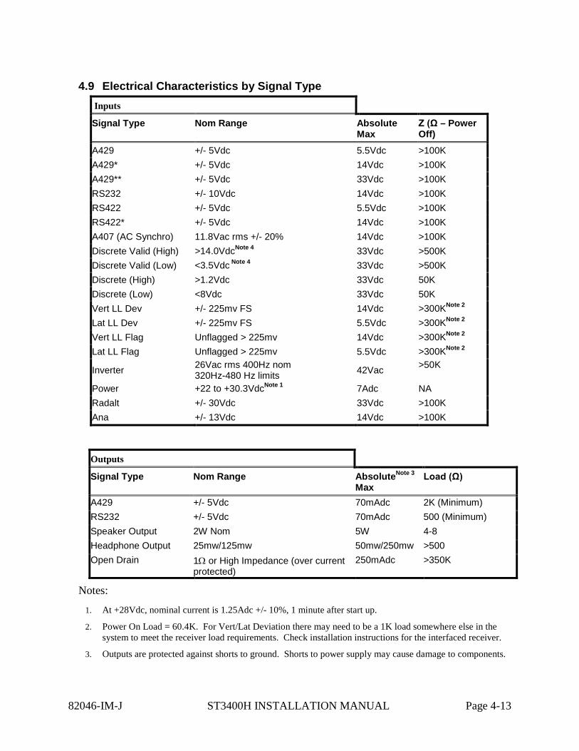
4.9 Electrical Characteristics by Signal Type Inputs
Signal Type Nom Range Absolute Max
Z (Ω – Power Off)
A429 +/- 5Vdc 5.5Vdc >100K A429* +/- 5Vdc 14Vdc >100K A429** +/- 5Vdc 33Vdc >100K RS232 +/- 10Vdc 14Vdc >100K RS422 +/- 5Vdc 5.5Vdc >100K RS422* +/- 5Vdc 14Vdc >100K A407 (AC Synchro) 11.8Vac rms +/- 20% 14Vdc >100K Discrete Valid (High) >14.0VdcNote 4 33Vdc >500K Discrete Valid (Low) <3.5Vdc Note 4 33Vdc >500K Discrete (High) >1.2Vdc 33Vdc 50K Discrete (Low) <8Vdc 33Vdc 50K Vert LL Dev +/- 225mv FS 14Vdc >300KNote 2 Lat LL Dev +/- 225mv FS 5.5Vdc >300KNote 2 Vert LL Flag Unflagged > 225mv 14Vdc >300KNote 2 Lat LL Flag Unflagged > 225mv 5.5Vdc >300KNote 2
Inverter 26Vac rms 400Hz nom 320Hz-480 Hz limits 42Vac >50K
Power +22 to +30.3VdcNote 1 7Adc NA Radalt +/- 30Vdc 33Vdc >100K Ana +/- 13Vdc 14Vdc >100K
Outputs
Signal Type Nom Range AbsoluteNote 3 Max
Load (Ω)
A429 +/- 5Vdc 70mAdc 2K (Minimum) RS232 +/- 5Vdc 70mAdc 500 (Minimum) Speaker Output 2W Nom 5W 4-8 Headphone Output 25mw/125mw 50mw/250mw >500 Open Drain 1Ω or High Impedance (over current
protected) 250mAdc >350K
Notes:
1. At +28Vdc, nominal current is 1.25Adc +/- 10%, 1 minute after start up.
2. Power On Load = 60.4K. For Vert/Lat Deviation there may need to be a 1K load somewhere else in the system to meet the receiver load requirements. Check installation instructions for the interfaced receiver.
3. Outputs are protected against shorts to ground. Shorts to power supply may cause damage to components.
82046-IM-J ST3400H INSTALLATION MANUAL Page 4-13

4. Discrete inputs actively pulled to 27.5v through 30k ohms when selected ‘active low’ or actively pulled to 0v through 30k ohms when selected ‘active high’ in the maintenance pages. This ensures the input is in the ‘inactive’ state if an external connection fails. If interfacing to discrete signals which do not supply a “hard” 0Vdc/27.5Vdc transition, any input network may be used that ensures that the discrete input pin is not within 1.0v from its nominal threshold shown in the table either in the active or inactive state.
5. All discrete outputs sink 50ua current when off.
82046-IM-J ST3400H INSTALLATION MANUAL Page 4-14
5 SETUP PROCEDURES
5.1 General
Setup procedures for the ST3400H are described along with the Maintenance menu below. The Maintenance Menu is accessed and addressed through the use of pushbuttons and the BRT/MINs knob. No external connector programming is required.
5.2 Accessing Maintenance Menus
To access the Maintenance Menus perform the following operations:
• Prior to applying power to the ST3400H, depress and hold the [MUTE] and [SENS] pushbuttons, then apply power to the unit. Continue to hold until the first maintenance menu appears.
• Once the Maintenance Menu is entered, press the [NEXT] or [PREV] soft-keys to cycle the MAINTENANCE MENU pages. To jump to a specific page, from the INDEX page, press the [UP] or [DOWN] soft-keys or rotate the BRT/MINS knob to move the cursor. Press the [SELECT] soft-key to jump to that page. On some menus additional soft-key legends will appear as prompts.
• Escape the maintenance menus by pressing and holding the “M” button. This will allow
normal operation of the unit to test the effects of the settings. Re-enter the maintenance pages by pressing and holding the “M” button.
To disable the maintenance menu operation, power down and restart normally. All configured items are stored in non-volatile memory.
5.3 Equipment/Configuration Selections
The choices of compatible equipment contained in the ST3400H menus are listed in section 8. For types not listed, consult the factory.
5.4 Configuration Module – (Reserved for future use)
The Configuration Module (CM) stores installation configurations. The physical Configuration Module is directly mounted to the rear of the instrument. Configuration module can be used when replacing an existing ST3400H. Data stored in the configuration module can be copied directly to the replacement unit. It is advisable to leave the configuration module plugged into the unit to avoid misplacing it.
5.5 Configuration Module Status Page - (Reserved for future use)
“CONFIG MODULE STATUS” page may appear during initial turn on and programming of a unit. This page will only appear again if there is a mismatch between the configuration information saved in the Configuration Module and the ST3400H. The mismatch identified
82046-IM-J ST3400H INSTALLATION MANUAL Page 5-1

with the configuration information is shown at the top of this page, along with the actions that may be taken.
The options displayed on the “CONFIG MODULE STATUS” page are as follows.
“DISABLE CM” (CM) When this option is selected no stored data will be read from or written to the Configuration Module. Selecting “Disable CM” will allow the installer to go directly to the Maintenance Index page 1.
Note “CM” will appear in the upper right corner to indicate that the configuration module is not operational.
“ST3400H TO CM”: stored The current ST3400H configuration is written to the configuration module and stored.
NOTE: When selecting this option ST3400H configuration data will be written TO the configuration module and overwrite any existing configuration data in the Configuration Module.
“CM TO ST3400H”: Selecting Stored Configuration Module data is written to the ST3400H.
NOTE: When selecting this option data FROM the configuration module will overwrite any existing configuration data in the ST3400H. The configuration module is unaffected.
As part of the configuration, an aircraft identifier (Tail Number) should be entered on the systems settings page.
82046-IM-J ST3400H INSTALLATION MANUAL Page 5-2

6 SYSTEM CONFIGURATION After all wiring has been verified and the ST3400H has been installed into the panel, the maintenance pages must be accessed to properly configure the ST3400H for the installed equipment. Prior to applying power to the ST3400H, press and hold the [MUTE] and [SENS] buttons, and then apply power to the unit. Continue to press the buttons until the first maintenance menu appears. Once the Maintenance Menu is entered, press the [NEXT] or [PREV] soft-keys to cycle the MAINTENANCE MENU pages. To jump to a specific page, from the INDEX page, press the [UP] or [DOWN] soft-key or rotate the knob to move the cursor. Press the [SELECT] soft-key to jump to that page. On some menus additional soft-key legends will appear as prompts. Escape the maintenance menus by pressing and holding the “M” button. This will allow normal operation of the unit to test the effects of the settings. Re-enter the maintenance pages by pressing and holding the “M” button. To disable the maintenance menu operation, power down and restart normally. All configured items are stored in non-volatile memory.
Page Number & Title
Cursor
Previous Page
Select Page
Toggle Mode Edit/Read
Mode Edit/Read
Next Page
Scroll Up
Scroll Down
The Maintenance Page Number/Title is displayed on every maintenance page showing the maintenance page number and title. The Cursor points to the item, which may be modified or selected. If there are no selectable items on the currently displayed maintenance page, the Current Line Indicator is not displayed.
• The [UP] and [DOWN] soft-keys are used to move the through the list. • The soft-keys are labeled to convey the context sensitive function of each button as
required.
82046-IM-J ST3400H INSTALLATION MANUAL Page 6-1
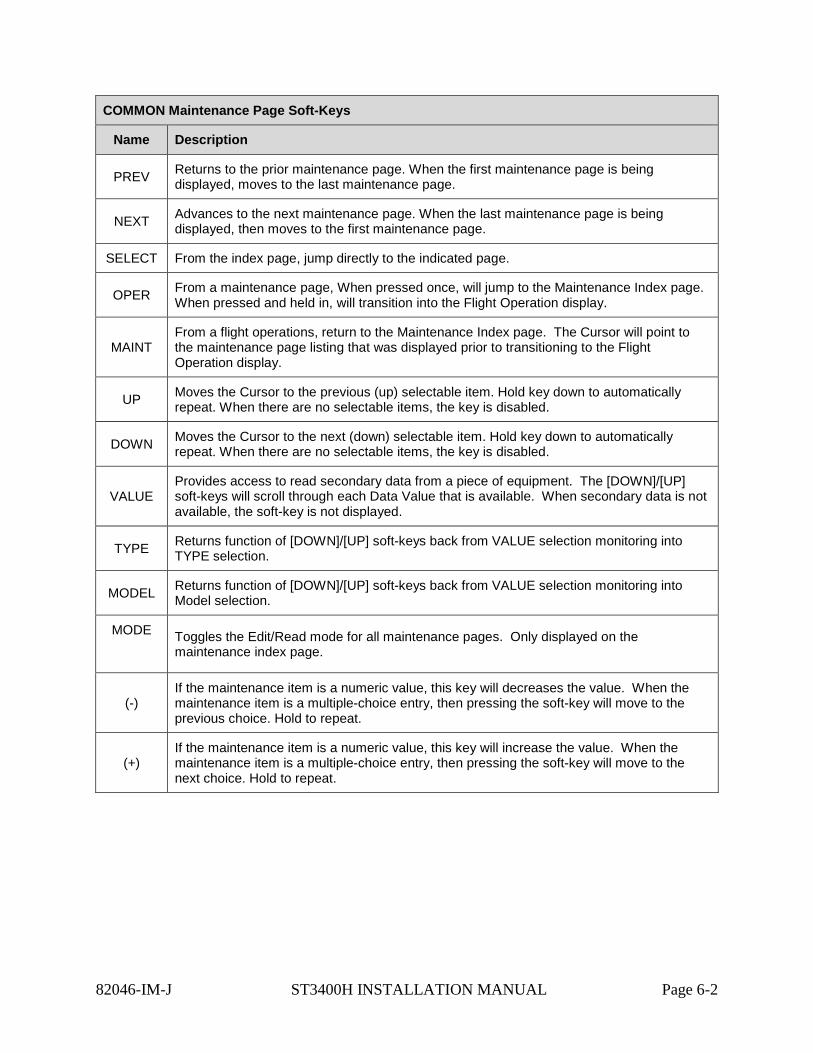
COMMON Maintenance Page Soft-Keys
Name Description
PREV Returns to the prior maintenance page. When the first maintenance page is being displayed, moves to the last maintenance page.
NEXT Advances to the next maintenance page. When the last maintenance page is being displayed, then moves to the first maintenance page.
SELECT From the index page, jump directly to the indicated page.
OPER From a maintenance page, When pressed once, will jump to the Maintenance Index page. When pressed and held in, will transition into the Flight Operation display.
MAINT From a flight operations, return to the Maintenance Index page. The Cursor will point to the maintenance page listing that was displayed prior to transitioning to the Flight Operation display.
UP Moves the Cursor to the previous (up) selectable item. Hold key down to automatically repeat. When there are no selectable items, the key is disabled.
DOWN Moves the Cursor to the next (down) selectable item. Hold key down to automatically repeat. When there are no selectable items, the key is disabled.
VALUE Provides access to read secondary data from a piece of equipment. The [DOWN]/[UP] soft-keys will scroll through each Data Value that is available. When secondary data is not available, the soft-key is not displayed.
TYPE Returns function of [DOWN]/[UP] soft-keys back from VALUE selection monitoring into TYPE selection.
MODEL Returns function of [DOWN]/[UP] soft-keys back from VALUE selection monitoring into Model selection.
MODE
Toggles the Edit/Read mode for all maintenance pages. Only displayed on the maintenance index page.
(-) If the maintenance item is a numeric value, this key will decreases the value. When the maintenance item is a multiple-choice entry, then pressing the soft-key will move to the previous choice. Hold to repeat.
(+) If the maintenance item is a numeric value, this key will increase the value. When the maintenance item is a multiple-choice entry, then pressing the soft-key will move to the next choice. Hold to repeat.
82046-IM-J ST3400H INSTALLATION MANUAL Page 6-2
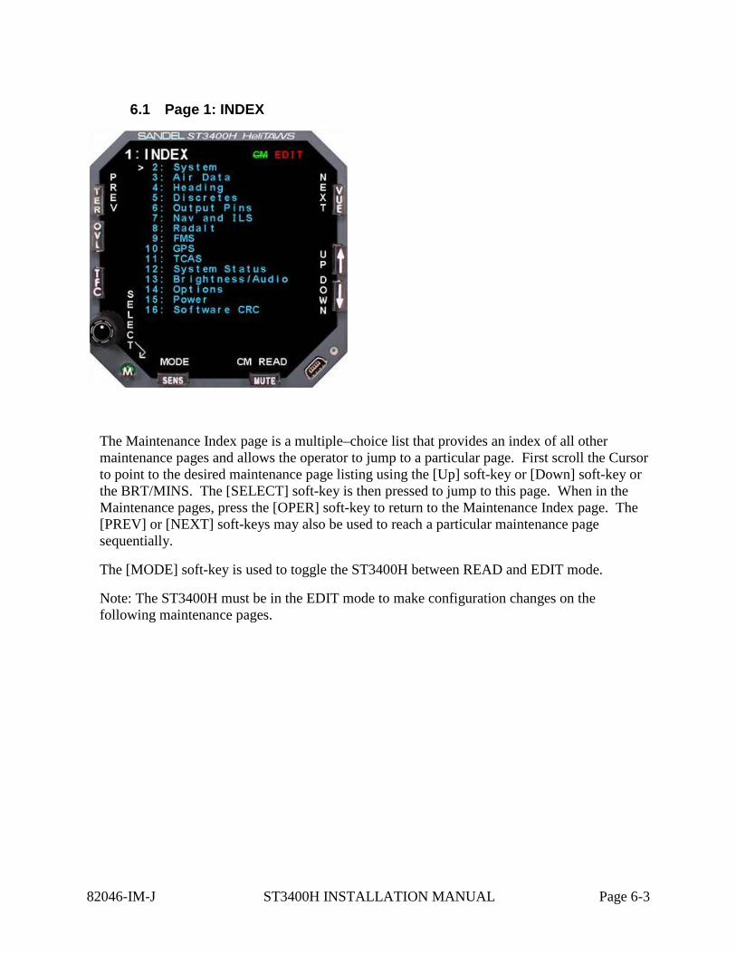
6.1 Page 1: INDEX
The Maintenance Index page is a multiple–choice list that provides an index of all other maintenance pages and allows the operator to jump to a particular page. First scroll the Cursor to point to the desired maintenance page listing using the [Up] soft-key or [Down] soft-key or the BRT/MINS. The [SELECT] soft-key is then pressed to jump to this page. When in the Maintenance pages, press the [OPER] soft-key to return to the Maintenance Index page. The [PREV] or [NEXT] soft-keys may also be used to reach a particular maintenance page sequentially.
The [MODE] soft-key is used to toggle the ST3400H between READ and EDIT mode.
Note: The ST3400H must be in the EDIT mode to make configuration changes on the following maintenance pages.
82046-IM-J ST3400H INSTALLATION MANUAL Page 6-3
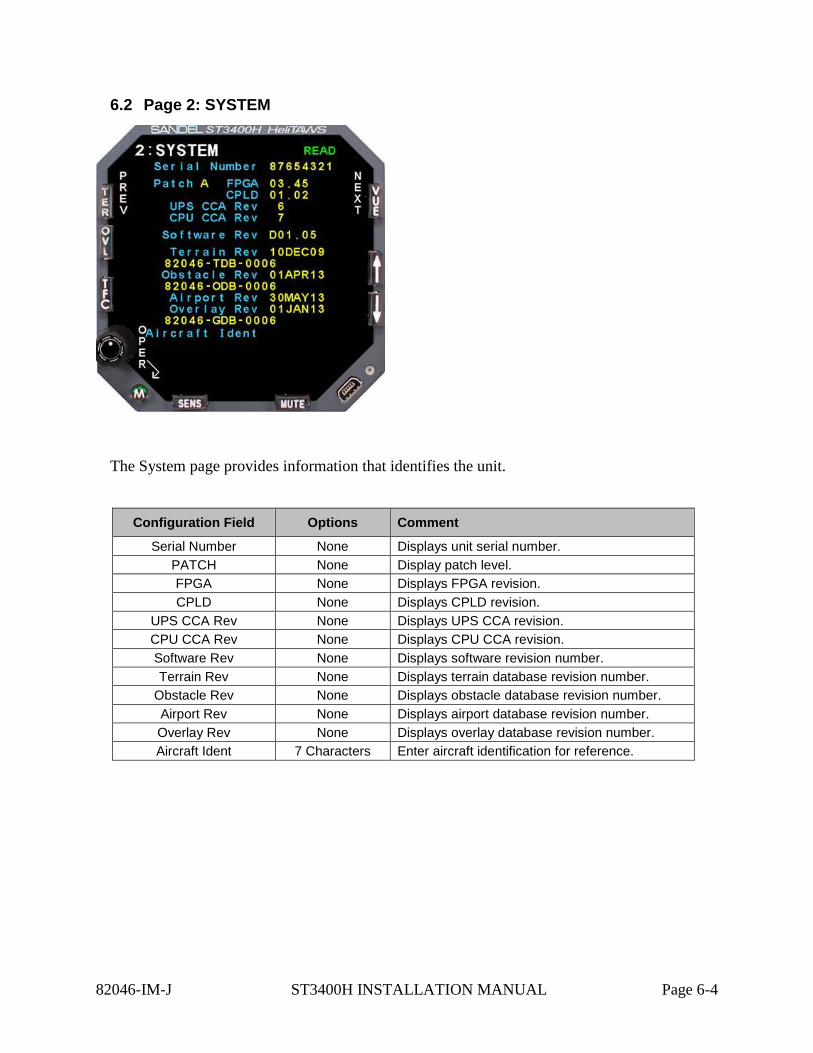
6.2 Page 2: SYSTEM
The System page provides information that identifies the unit.
Configuration Field Options Comment
Serial Number None Displays unit serial number. PATCH None Display patch level. FPGA None Displays FPGA revision. CPLD None Displays CPLD revision.
UPS CCA Rev None Displays UPS CCA revision. CPU CCA Rev None Displays CPU CCA revision. Software Rev None Displays software revision number. Terrain Rev None Displays terrain database revision number.
Obstacle Rev None Displays obstacle database revision number. Airport Rev None Displays airport database revision number. Overlay Rev None Displays overlay database revision number. Aircraft Ident 7 Characters Enter aircraft identification for reference.
82046-IM-J ST3400H INSTALLATION MANUAL Page 6-4
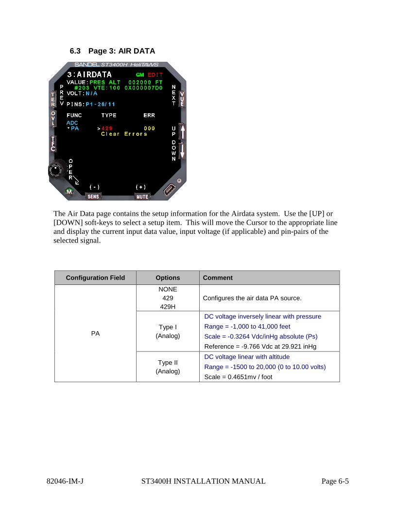
6.3 Page 3: AIR DATA
The Air Data page contains the setup information for the Airdata system. Use the [UP] or [DOWN] soft-keys to select a setup item. This will move the Cursor to the appropriate line and display the current input data value, input voltage (if applicable) and pin-pairs of the selected signal.
Configuration Field Options Comment
PA
NONE 429
429H Configures the air data PA source.
Type I (Analog)
DC voltage inversely linear with pressure Range = -1,000 to 41,000 feet Scale = -0.3264 Vdc/inHg absolute (Ps) Reference = -9.766 Vdc at 29.921 inHg
Type II (Analog)
DC voltage linear with altitude Range = -1500 to 20,000 (0 to 10.00 volts) Scale = 0.4651mv / foot
82046-IM-J ST3400H INSTALLATION MANUAL Page 6-5
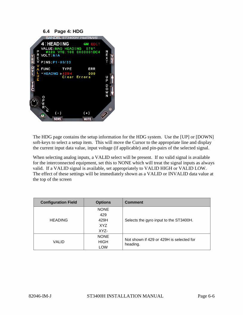
6.4 Page 4: HDG
The HDG page contains the setup information for the HDG system. Use the [UP] or [DOWN] soft-keys to select a setup item. This will move the Cursor to the appropriate line and display the current input data value, input voltage (if applicable) and pin-pairs of the selected signal.
When selecting analog inputs, a VALID select will be present. If no valid signal is available for the interconnected equipment, set this to NONE which will treat the signal inputs as always valid. If a VALID signal is available, set appropriately to VALID HIGH or VALID LOW. The effect of these settings will be immediately shown as a VALID or INVALID data value at the top of the screen
Configuration Field Options Comment
HEADING
NONE 429
429H XYZ XYZ-
Selects the gyro input to the ST3400H.
VALID NONE HIGH LOW
Not shown if 429 or 429H is selected for heading.
82046-IM-J ST3400H INSTALLATION MANUAL Page 6-6
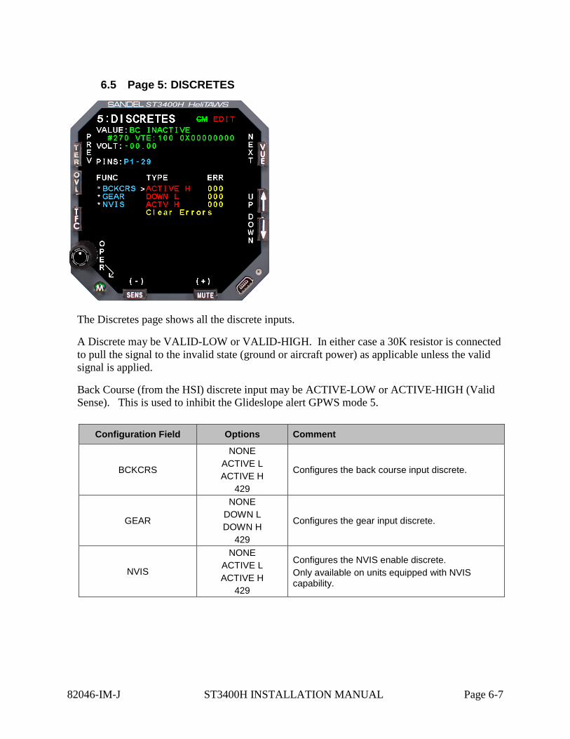
6.5 Page 5: DISCRETES
The Discretes page shows all the discrete inputs.
A Discrete may be VALID-LOW or VALID-HIGH. In either case a 30K resistor is connected to pull the signal to the invalid state (ground or aircraft power) as applicable unless the valid signal is applied.
Back Course (from the HSI) discrete input may be ACTIVE-LOW or ACTIVE-HIGH (Valid Sense). This is used to inhibit the Glideslope alert GPWS mode 5.
Configuration Field Options Comment
BCKCRS
NONE ACTIVE L ACTIVE H
429
Configures the back course input discrete.
GEAR
NONE DOWN L DOWN H
429
Configures the gear input discrete.
NVIS
NONE ACTIVE L ACTIVE H
429
Configures the NVIS enable discrete. Only available on units equipped with NVIS capability.
82046-IM-J ST3400H INSTALLATION MANUAL Page 6-7
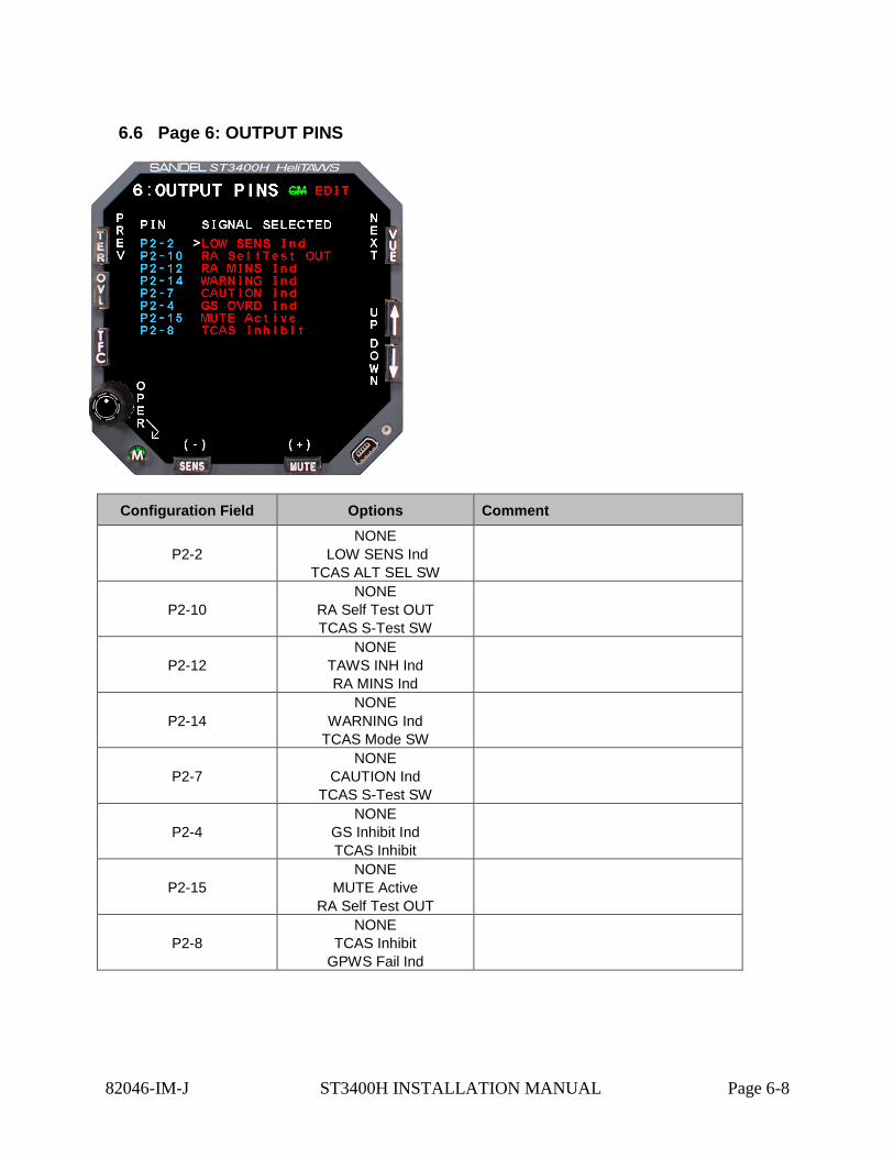
6.6 Page 6: OUTPUT PINS
Configuration Field Options Comment
P2-2 NONE
LOW SENS Ind TCAS ALT SEL SW
P2-10 NONE
RA Self Test OUT TCAS S-Test SW
P2-12 NONE
TAWS INH Ind RA MINS Ind
P2-14 NONE
WARNING Ind TCAS Mode SW
P2-7 NONE
CAUTION Ind TCAS S-Test SW
P2-4 NONE
GS Inhibit Ind TCAS Inhibit
P2-15 NONE
MUTE Active RA Self Test OUT
P2-8 NONE
TCAS Inhibit GPWS Fail Ind
82046-IM-J ST3400H INSTALLATION MANUAL Page 6-8
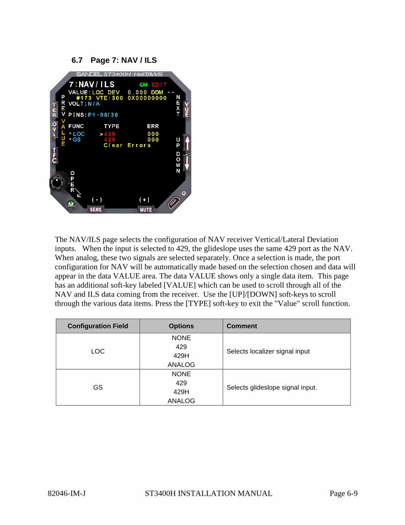
6.7 Page 7: NAV / ILS
The NAV/ILS page selects the configuration of NAV receiver Vertical/Lateral Deviation inputs. When the input is selected to 429, the glideslope uses the same 429 port as the NAV. When analog, these two signals are selected separately. Once a selection is made, the port configuration for NAV will be automatically made based on the selection chosen and data will appear in the data VALUE area. The data VALUE shows only a single data item. This page has an additional soft-key labeled [VALUE] which can be used to scroll through all of the NAV and ILS data coming from the receiver. Use the [UP]/[DOWN] soft-keys to scroll through the various data items. Press the [TYPE] soft-key to exit the "Value" scroll function.
Configuration Field Options Comment
LOC
NONE 429
429H ANALOG
Selects localizer signal input
GS
NONE 429
429H ANALOG
Selects glideslope signal input.
82046-IM-J ST3400H INSTALLATION MANUAL Page 6-9
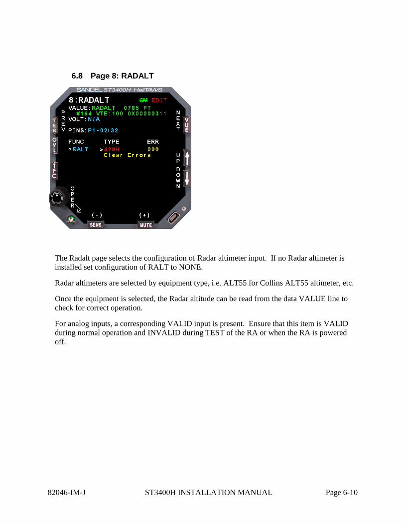
6.8 Page 8: RADALT
The Radalt page selects the configuration of Radar altimeter input. If no Radar altimeter is installed set configuration of RALT to NONE.
Radar altimeters are selected by equipment type, i.e. ALT55 for Collins ALT55 altimeter, etc.
Once the equipment is selected, the Radar altitude can be read from the data VALUE line to check for correct operation.
For analog inputs, a corresponding VALID input is present. Ensure that this item is VALID during normal operation and INVALID during TEST of the RA or when the RA is powered off.
82046-IM-J ST3400H INSTALLATION MANUAL Page 6-10
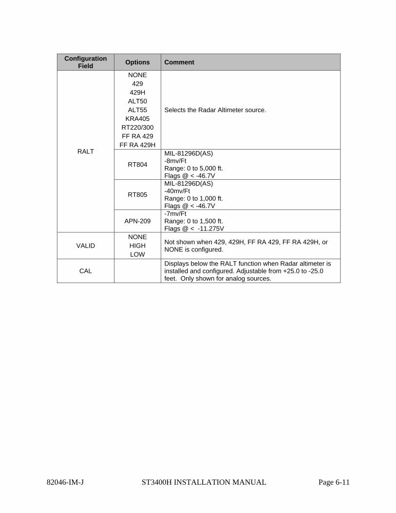
82046-IM-J ST3400H INSTALLATION MANUAL Page 6-11
Configuration Field Options Comment
RALT
NONE 429
429H ALT50 ALT55
KRA405 RT220/300 FF RA 429
FF RA 429H
Selects the Radar Altimeter source.
RT804
MIL-81296D(AS) -8mv/Ft Range: 0 to 5,000 ft. Flags @ < -46.7V
RT805
MIL-81296D(AS) -40mv/Ft Range: 0 to 1,000 ft. Flags @ < -46.7V
APN-209 -7mv/Ft Range: 0 to 1,500 ft. Flags @ < -11.275V
VALID NONE HIGH LOW
Not shown when 429, 429H, FF RA 429, FF RA 429H, or NONE is configured.
CAL Displays below the RALT function when Radar altimeter is installed and configured. Adjustable from +25.0 to -25.0 feet. Only shown for analog sources.
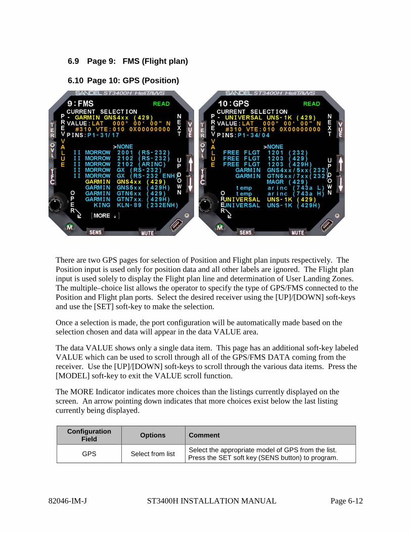
6.9 Page 9: FMS (Flight plan)
6.10 Page 10: GPS (Position)
There are two GPS pages for selection of Position and Flight plan inputs respectively. The Position input is used only for position data and all other labels are ignored. The Flight plan input is used solely to display the Flight plan line and determination of User Landing Zones. The multiple–choice list allows the operator to specify the type of GPS/FMS connected to the Position and Flight plan ports. Select the desired receiver using the [UP]/[DOWN] soft-keys and use the [SET] soft-key to make the selection.
Once a selection is made, the port configuration will be automatically made based on the selection chosen and data will appear in the data VALUE area.
The data VALUE shows only a single data item. This page has an additional soft-key labeled VALUE which can be used to scroll through all of the GPS/FMS DATA coming from the receiver. Use the [UP]/[DOWN] soft-keys to scroll through the various data items. Press the [MODEL] soft-key to exit the VALUE scroll function.
The MORE Indicator indicates more choices than the listings currently displayed on the screen. An arrow pointing down indicates that more choices exist below the last listing currently being displayed.
Configuration Field Options Comment
GPS Select from list Select the appropriate model of GPS from the list. Press the SET soft key (SENS button) to program.
82046-IM-J ST3400H INSTALLATION MANUAL Page 6-12

6.11 Page 11: TCAS
The TCAS page shows selections available for Traffic.
The multiple–choice list allows the operator to specify the type of Traffic processor connected to the Traffic port. Select using the [UP]/[DOWN] soft-keys and use the [SET] soft-key to make the selection.
Once a selection is made, the port configuration for Traffic will be automatically made based on the selection chosen and data will appear in the data VALUE area.
This page has an additional soft-key labeled VALUE which can be used to scroll through all of the TCAS DATA coming from the processor. Use the [UP]/[DOWN] soft-keys to scroll through the various data items. Press the [MODEL] soft-key to exit the VALUE scroll function.
The MORE Indicator indicates more choices than the listings currently displayed on the screen. An arrow pointing down indicates that more choices exist below the last listing currently being displayed.
82046-IM-J ST3400H INSTALLATION MANUAL Page 6-13

Configuration Field Options Comment
TCAS KEY Blank by default
Enter the purchased 11 character key code to enable traffic. Use the MUTE and SENS keys to select the character and the OVLY and TFC keys to move the cursor.
TCAS Model
Collins TCAS 4000 Goodrich Skywatch
Goodrich Skywatch (SW) Goodrich SkywatchHP
Goodrich SkywatchHP (SW) Goodrich TCAS791/A
Goodrich TCAS791/A (SW) Honeywell CAS-66 Honeywell CAS-67 Honeywell CAS-81 Ryan 9900BX TAS
Select the appropriate model of GPS from the list. Press the SET soft key (SENS button) to program.
Note: The Goodrich TFC Displays include push buttons to control the TFC processor (Skywatch, Skywatch HP, and TCAS791). If it is desired to use the ST3400H as the TFC display; those button functions need to be retained. This can be accomplished by either using a panel mounted set of buttons or configuring the ST3400H to support ‘soft-key’ labeled buttons by selecting the proper choice that includes the (SW) reference.
82046-IM-J ST3400H INSTALLATION MANUAL Page 6-14
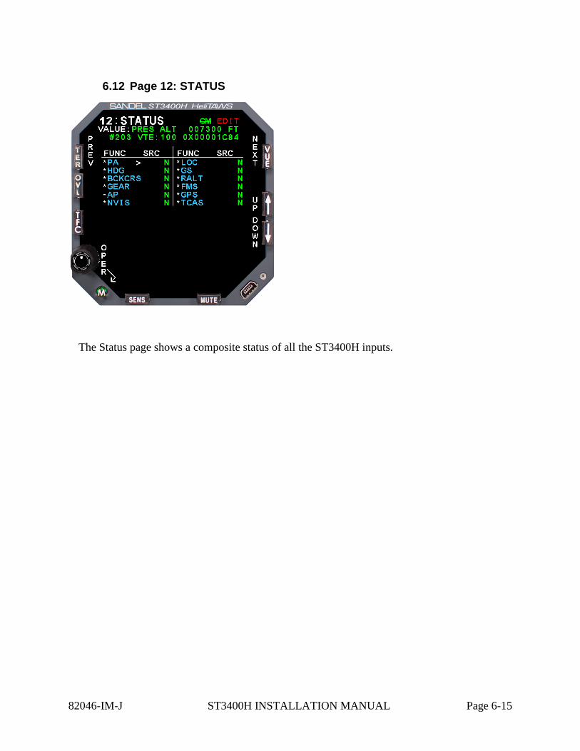
6.12 Page 12: STATUS
The Status page shows a composite status of all the ST3400H inputs.
82046-IM-J ST3400H INSTALLATION MANUAL Page 6-15
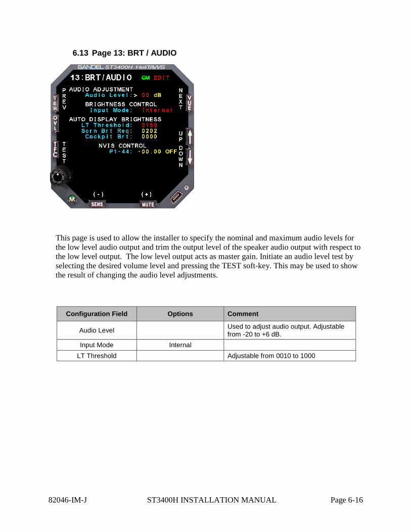
6.13 Page 13: BRT / AUDIO
This page is used to allow the installer to specify the nominal and maximum audio levels for the low level audio output and trim the output level of the speaker audio output with respect to the low level output. The low level output acts as master gain. Initiate an audio level test by selecting the desired volume level and pressing the TEST soft-key. This may be used to show the result of changing the audio level adjustments.
Configuration Field Options Comment
Audio Level Used to adjust audio output. Adjustable from -20 to +6 dB.
Input Mode Internal LT Threshold Adjustable from 0010 to 1000
82046-IM-J ST3400H INSTALLATION MANUAL Page 6-16
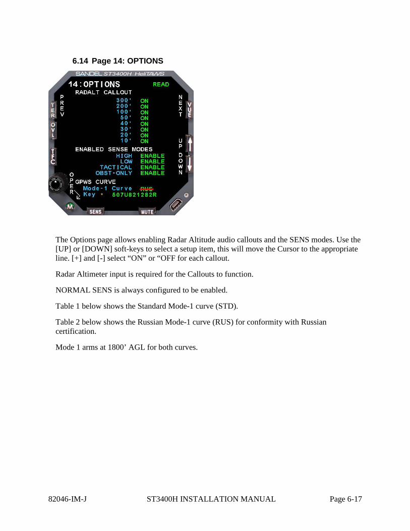
6.14 Page 14: OPTIONS
The Options page allows enabling Radar Altitude audio callouts and the SENS modes. Use the [UP] or [DOWN] soft-keys to select a setup item, this will move the Cursor to the appropriate line. [+] and [-] select “ON” or “OFF for each callout.
Radar Altimeter input is required for the Callouts to function.
NORMAL SENS is always configured to be enabled.
Table 1 below shows the Standard Mode-1 curve (STD).
Table 2 below shows the Russian Mode-1 curve (RUS) for conformity with Russian certification.
Mode 1 arms at 1800’ AGL for both curves.
82046-IM-J ST3400H INSTALLATION MANUAL Page 6-17
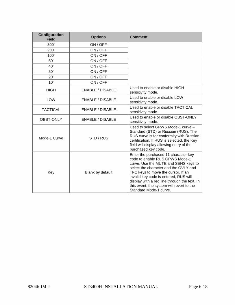
Configuration Field Options Comment
300’ ON / OFF
200’ ON / OFF 100’ ON / OFF 50’ ON / OFF 40’ ON / OFF 30’ ON / OFF 20’ ON / OFF 10’ ON / OFF
HIGH ENABLE / DISABLE Used to enable or disable HIGH sensitivity mode.
LOW ENABLE / DISABLE Used to enable or disable LOW sensitivity mode.
TACTICAL ENABLE / DISABLE Used to enable or disable TACTICAL sensitivity mode.
OBST-ONLY ENABLE / DISABLE Used to enable or disable OBST-ONLY sensitivity mode.
Mode-1 Curve STD / RUS
Used to select GPWS Mode-1 curve – Standard (STD) or Russian (RUS). The RUS curve is for conformity with Russian certification. If RUS is selected, the Key field will display allowing entry of the purchased key code.
Key Blank by default
Enter the purchased 11 character key code to enable RUS GPWS Mode-1 curve. Use the MUTE and SENS keys to select the character and the OVLY and TFC keys to move the cursor. If an invalid key code is entered, RUS will display with a red line through the text. In this event, the system will revert to the Standard Mode-1 curve.
82046-IM-J ST3400H INSTALLATION MANUAL Page 6-18
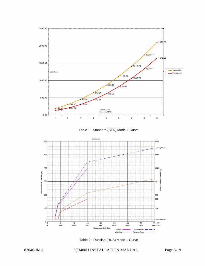
Table 1 - Standard (STD) Mode-1 Curve
Table 2 - Russian (RUS) Mode-1 Curve
82046-IM-J ST3400H INSTALLATION MANUAL Page 6-19
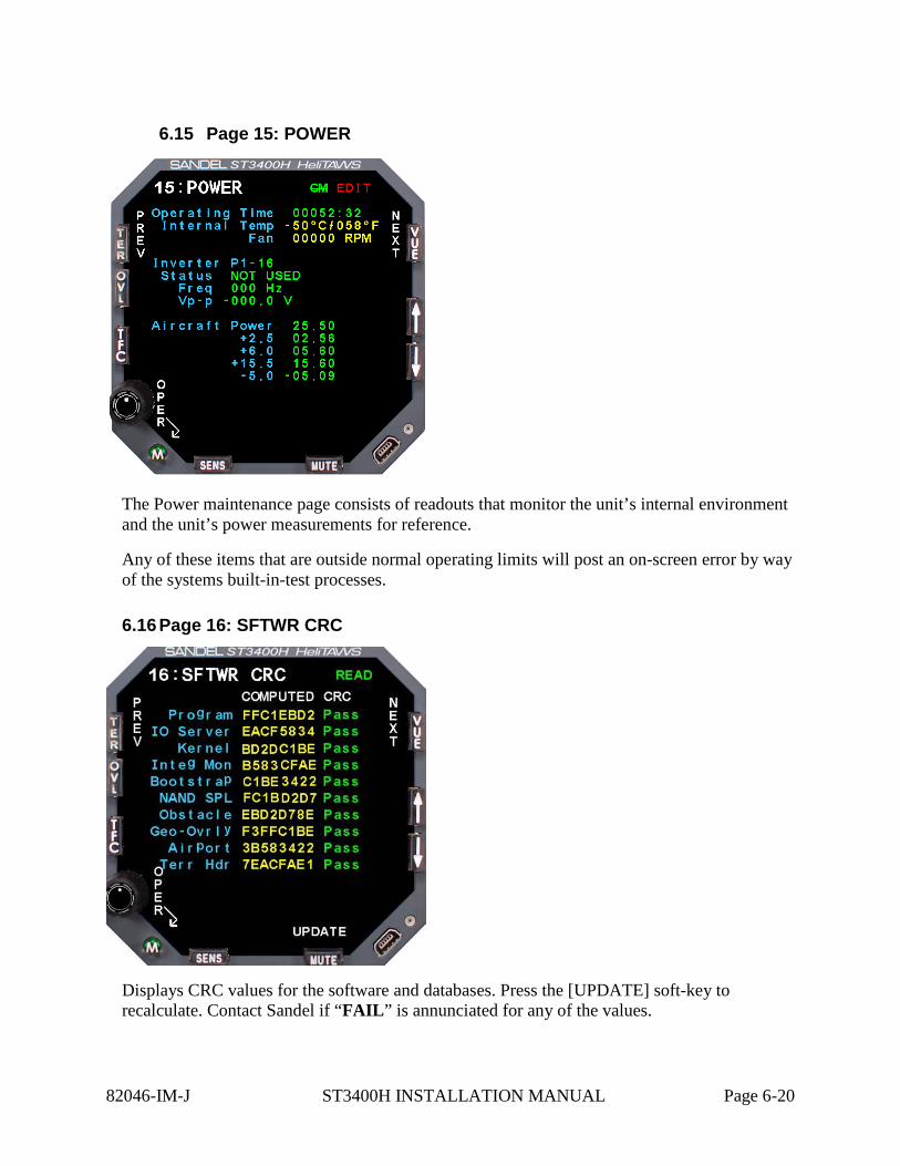
6.15 Page 15: POWER
The Power maintenance page consists of readouts that monitor the unit’s internal environment and the unit’s power measurements for reference.
Any of these items that are outside normal operating limits will post an on-screen error by way of the systems built-in-test processes.
6.16 Page 16: SFTWR CRC
Displays CRC values for the software and databases. Press the [UPDATE] soft-key to recalculate. Contact Sandel if “FAIL” is annunciated for any of the values.
82046-IM-J ST3400H INSTALLATION MANUAL Page 6-20

7 CHECKOUT PROCEDURES Perform all of the following tests. All tests must pass (or be not applicable) for return to service.
7.1 Power-On Self-Test
The Power-On Self-Test capability is an automatic test of equipment condition. It executes during the power-up sequence and reports any internal errors via on-screen readouts. The failure of the display itself is a major failure and will result in the inability to show further system-level error messages.
7.2 ST3400H TAWS
Verify DC Power, AC Power and Ground inputs to the ST3400H connectors before installing the ST3400H.
7.3 Install Sandel ST3400H TAWS into aircraft
Enter the maintenance mode by press and holding the SENS and MUTE buttons while applying power to the ST3400H. Continue to hold until the ST3400H screen is active.
7.4 Record the following Aircraft Information
Aircraft Make: Aircraft Model:
Aircraft S/N: Aircraft Registration:
7.5 Record the following system information:
Date:
ST3400H S/N:
Software Rev:
Terrain Database Area and Rev:
Obstacle Database Area and Rev:
Airport Database Area and Rev:
7.6 Required Test Equipment: • ILS Ramp Test Set • Multi-meter • Radar Altimeter with Test button, or Radar Altimeter Test Set
82046-IM-J ST3400H INSTALLATION MANUAL Page 7-1
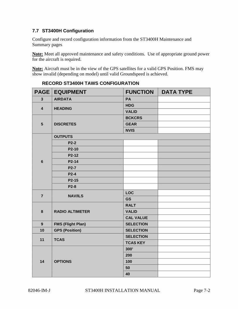
7.7 ST3400H Configuration
Configure and record configuration information from the ST3400H Maintenance and Summary pages
Note: Meet all approved maintenance and safety conditions. Use of appropriate ground power for the aircraft is required.
Note: Aircraft must be in the view of the GPS satellites for a valid GPS Position. FMS may show invalid (depending on model) until valid Groundspeed is achieved.
RECORD ST3400H TAWS CONFIGURATION
PAGE EQUIPMENT FUNCTION DATA TYPE 3 AIRDATA PA
4 HEADING HDG VALID
5 DISCRETES BCKCRS GEAR NVIS
6
OUTPUTS P2-2 P2-10 P2-12 P2-14 P2-7 P2-4 P2-15 P2-8
7 NAV/ILS LOC GS
8 RADIO ALTIMETER RALT VALID CAL VALUE
9 FMS (Flight Plan) SELECTION 10 GPS (Position) SELECTION
11 TCAS SELECTION TCAS KEY
14 OPTIONS
300’ 200 100 50 40
82046-IM-J ST3400H INSTALLATION MANUAL Page 7-2
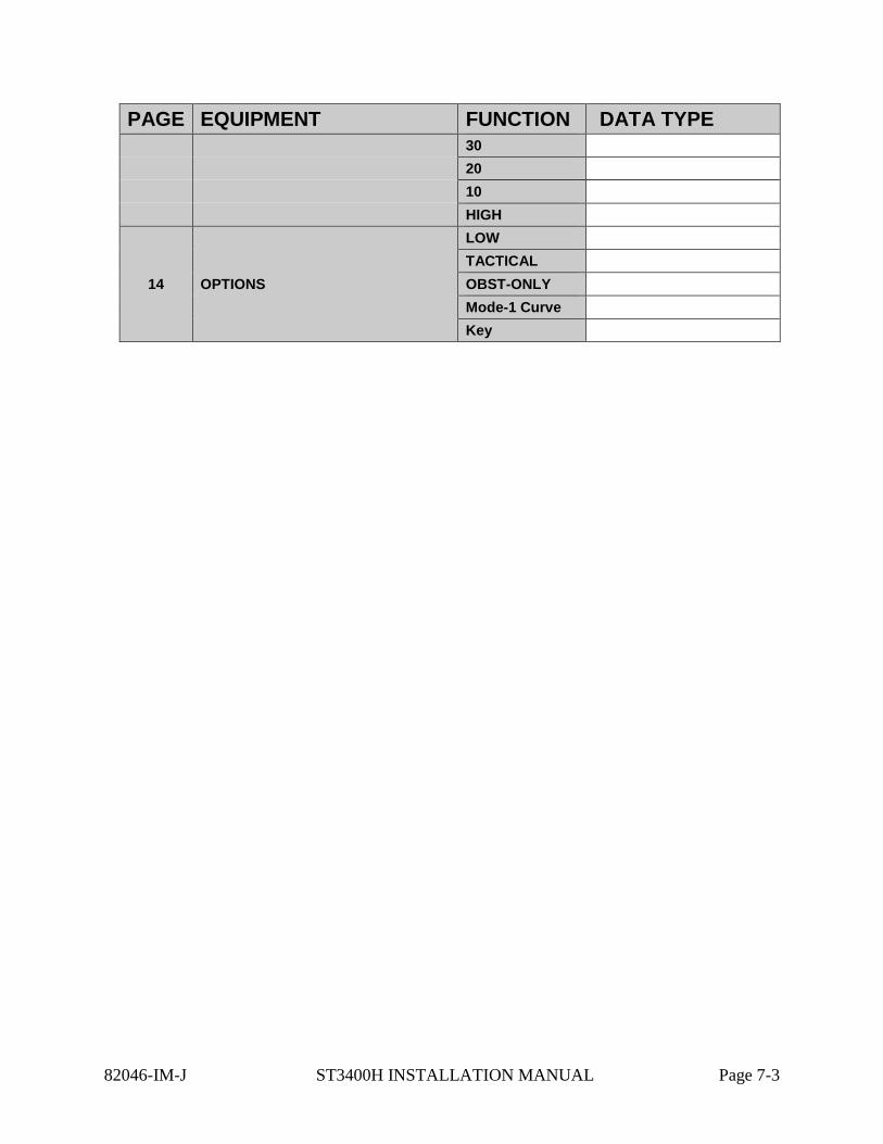
PAGE EQUIPMENT FUNCTION DATA TYPE 30 20 10 HIGH
14 OPTIONS
LOW TACTICAL OBST-ONLY Mode-1 Curve Key
82046-IM-J ST3400H INSTALLATION MANUAL Page 7-3
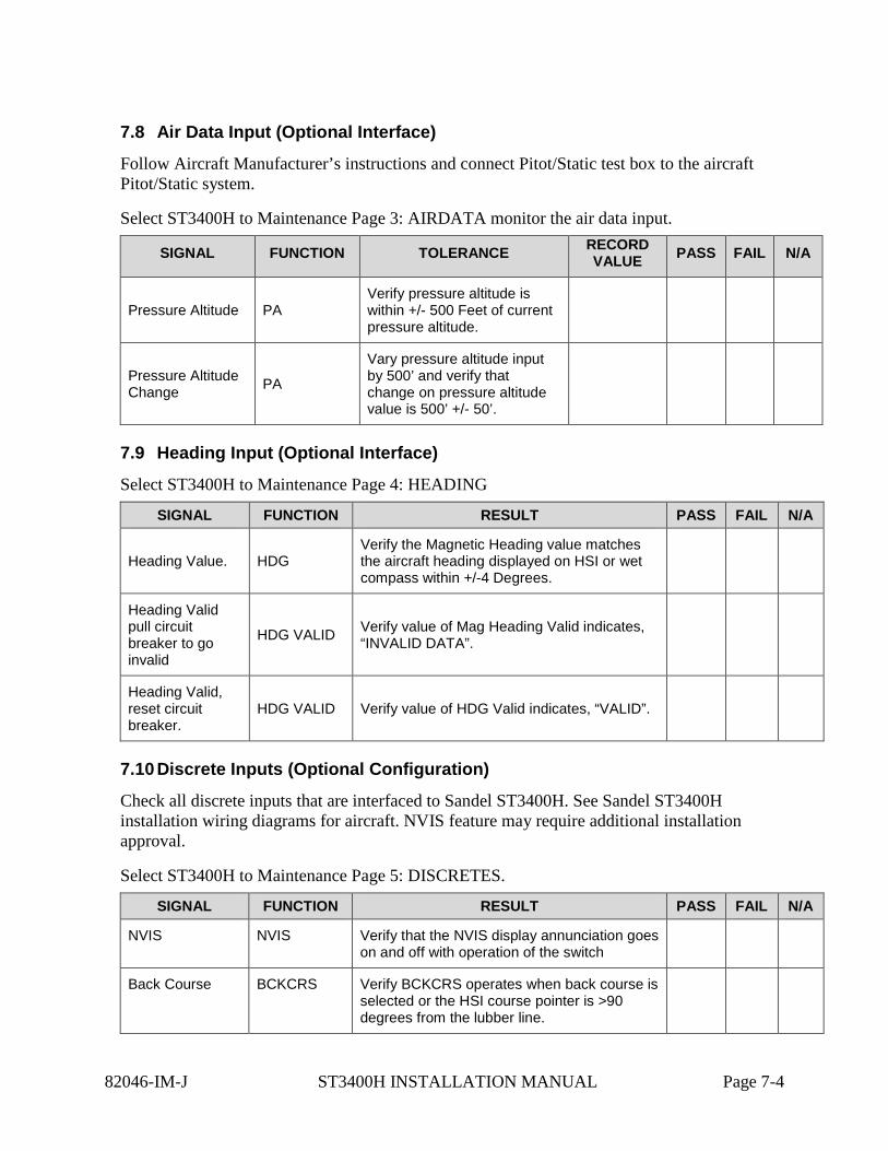
7.8 Air Data Input (Optional Interface)
Follow Aircraft Manufacturer’s instructions and connect Pitot/Static test box to the aircraft Pitot/Static system.
Select ST3400H to Maintenance Page 3: AIRDATA monitor the air data input.
SIGNAL FUNCTION TOLERANCE RECORD VALUE PASS FAIL N/A
Pressure Altitude PA Verify pressure altitude is within +/- 500 Feet of current pressure altitude.
Pressure Altitude Change PA
Vary pressure altitude input by 500’ and verify that change on pressure altitude value is 500’ +/- 50’.
7.9 Heading Input (Optional Interface)
Select ST3400H to Maintenance Page 4: HEADING
SIGNAL FUNCTION RESULT PASS FAIL N/A
Heading Value. HDG Verify the Magnetic Heading value matches the aircraft heading displayed on HSI or wet compass within +/-4 Degrees.
Heading Valid pull circuit breaker to go invalid
HDG VALID Verify value of Mag Heading Valid indicates, “INVALID DATA”.
Heading Valid, reset circuit breaker.
HDG VALID Verify value of HDG Valid indicates, “VALID”.
7.10 Discrete Inputs (Optional Configuration)
Check all discrete inputs that are interfaced to Sandel ST3400H. See Sandel ST3400H installation wiring diagrams for aircraft. NVIS feature may require additional installation approval.
Select ST3400H to Maintenance Page 5: DISCRETES.
SIGNAL FUNCTION RESULT PASS FAIL N/A
NVIS NVIS Verify that the NVIS display annunciation goes on and off with operation of the switch
Back Course BCKCRS Verify BCKCRS operates when back course is selected or the HSI course pointer is >90 degrees from the lubber line.
82046-IM-J ST3400H INSTALLATION MANUAL Page 7-4
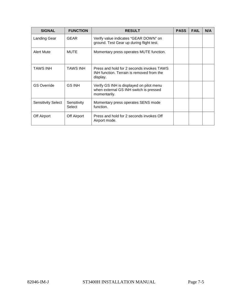
SIGNAL FUNCTION RESULT PASS FAIL N/A
Landing Gear GEAR Verify value indicates “GEAR DOWN” on ground. Test Gear up during flight test.
Alert Mute MUTE
Momentary press operates MUTE function.
TAWS INH TAWS INH Press and hold for 2 seconds invokes TAWS INH function. Terrain is removed from the display.
GS Override GS INH Verify GS INH is displayed on pilot menu when external GS INH switch is pressed momentarily.
Sensitivity Select Sensitivity Select
Momentary press operates SENS mode function.
Off Airport Off Airport Press and hold for 2 seconds invokes Off Airport mode.
82046-IM-J ST3400H INSTALLATION MANUAL Page 7-5
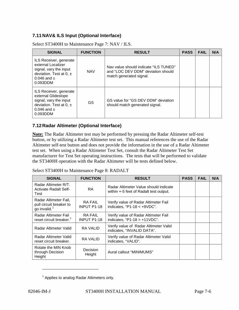
7.11 NAV& ILS Input (Optional Interface)
Select ST3400H to Maintenance Page 7: NAV / ILS.
SIGNAL FUNCTION RESULT PASS FAIL N/A
ILS Receiver, generate external Localizer signal, vary the input deviation. Test at 0, ± 0.046 and ± 0.093DDM
NAV Nav value should indicate “ILS TUNED” and “LOC DEV DDM” deviation should match generated signal.
ILS Receiver, generate external Glideslope signal, vary the input deviation. Test at 0, ± 0.046 and ± 0.093DDM
GS GS value for “GS DEV DDM” deviation should match generated signal.
7.12 Radar Altimeter (Optional Interface)
Note: The Radar Altimeter test may be performed by pressing the Radar Altimeter self-test button, or by utilizing a Radar Altimeter test set. This manual references the use of the Radar Altimeter self-test button and does not provide the information in the use of a Radar Altimeter test set. When using a Radar Altimeter Test Set, consult the Radar Altimeter Test Set manufacturer for Test Set operating instructions. The tests that will be performed to validate the ST3400H operation with the Radar Altimeter will be tests defined below.
Select ST3400H to Maintenance Page 8: RADALT SIGNAL FUNCTION RESULT PASS FAIL N/A
Radar Altimeter R/T. Activate Radalt Self-Test
RA Radar Altimeter Value should indicate within +-5 feet of Radalt test output.
Radar Altimeter Fail, pull circuit breaker to go invalid.1
RA FAIL INPUT P1-18
Verify value of Radar Altimeter Fail indicates, “P1-18 < +9VDC”.
Radar Altimeter Fail reset circuit breaker.1
RA FAIL INPUT P1-18
Verify value of Radar Altimeter Fail indicates, “P1-18 > +11VDC”.
Radar Altimeter Valid RA VALID Verify value of Radar Altimeter Valid indicates, “INVALID DATA”.
Radar Altimeter Valid reset circuit breaker. RA VALID Verify value of Radar Altimeter Valid
indicates, “VALID”.
Rotate the MIN Knob through Decision Height
Decision Height Aural callout “MINIMUMS”
1 Applies to analog Radar Altimeters only.
82046-IM-J ST3400H INSTALLATION MANUAL Page 7-6
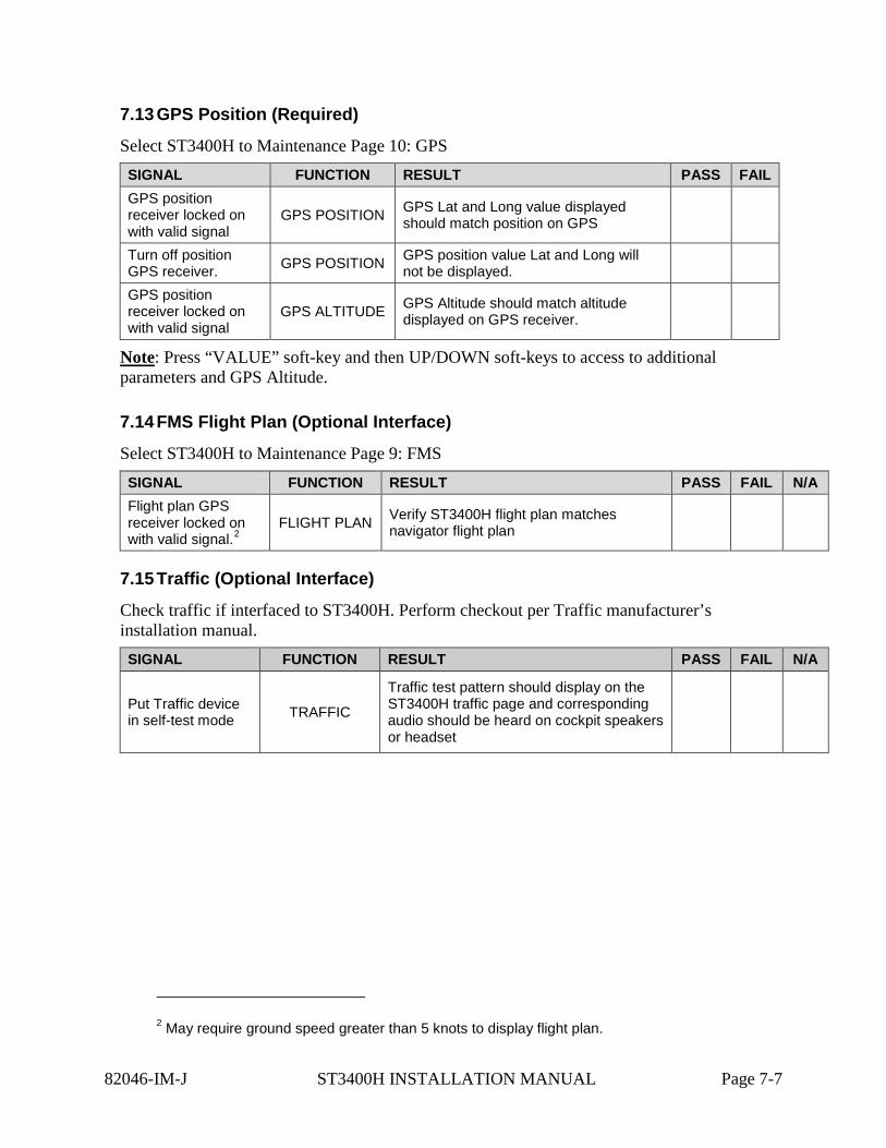
7.13 GPS Position (Required)
Select ST3400H to Maintenance Page 10: GPS SIGNAL FUNCTION RESULT PASS FAIL GPS position receiver locked on with valid signal
GPS POSITION GPS Lat and Long value displayed should match position on GPS
Turn off position GPS receiver. GPS POSITION GPS position value Lat and Long will
not be displayed.
GPS position receiver locked on with valid signal
GPS ALTITUDE GPS Altitude should match altitude displayed on GPS receiver.
Note: Press “VALUE” soft-key and then UP/DOWN soft-keys to access to additional parameters and GPS Altitude.
7.14 FMS Flight Plan (Optional Interface)
Select ST3400H to Maintenance Page 9: FMS SIGNAL FUNCTION RESULT PASS FAIL N/A Flight plan GPS receiver locked on with valid signal.2
FLIGHT PLAN Verify ST3400H flight plan matches navigator flight plan
7.15 Traffic (Optional Interface)
Check traffic if interfaced to ST3400H. Perform checkout per Traffic manufacturer’s installation manual. SIGNAL FUNCTION RESULT PASS FAIL N/A
Put Traffic device in self-test mode TRAFFIC
Traffic test pattern should display on the ST3400H traffic page and corresponding audio should be heard on cockpit speakers or headset
2 May require ground speed greater than 5 knots to display flight plan.
82046-IM-J ST3400H INSTALLATION MANUAL Page 7-7
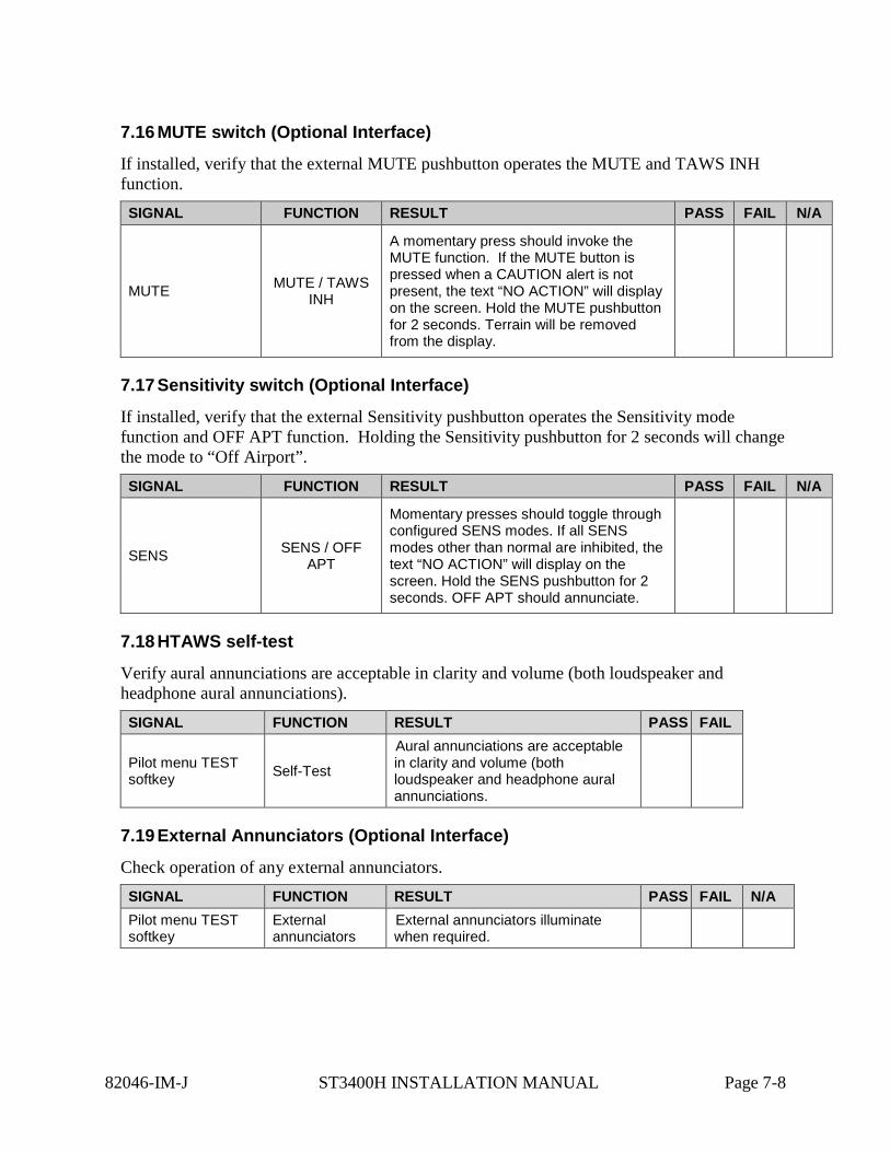
7.16 MUTE switch (Optional Interface)
If installed, verify that the external MUTE pushbutton operates the MUTE and TAWS INH function. SIGNAL FUNCTION RESULT PASS FAIL N/A
MUTE MUTE / TAWS INH
A momentary press should invoke the MUTE function. If the MUTE button is pressed when a CAUTION alert is not present, the text “NO ACTION” will display on the screen. Hold the MUTE pushbutton for 2 seconds. Terrain will be removed from the display.
7.17 Sensitivity switch (Optional Interface)
If installed, verify that the external Sensitivity pushbutton operates the Sensitivity mode function and OFF APT function. Holding the Sensitivity pushbutton for 2 seconds will change the mode to “Off Airport”. SIGNAL FUNCTION RESULT PASS FAIL N/A
SENS SENS / OFF APT
Momentary presses should toggle through configured SENS modes. If all SENS modes other than normal are inhibited, the text “NO ACTION” will display on the screen. Hold the SENS pushbutton for 2 seconds. OFF APT should annunciate.
7.18 HTAWS self-test
Verify aural annunciations are acceptable in clarity and volume (both loudspeaker and headphone aural annunciations). SIGNAL FUNCTION RESULT PASS FAIL
Pilot menu TEST softkey Self-Test
Aural annunciations are acceptable in clarity and volume (both loudspeaker and headphone aural annunciations.
7.19 External Annunciators (Optional Interface)
Check operation of any external annunciators. SIGNAL FUNCTION RESULT PASS FAIL N/A Pilot menu TEST softkey
External annunciators
External annunciators illuminate when required.
82046-IM-J ST3400H INSTALLATION MANUAL Page 7-8
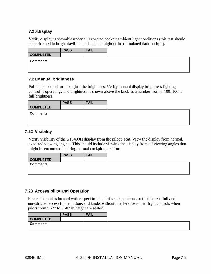
7.20 Display
Verify display is viewable under all expected cockpit ambient light conditions (this test should be performed in bright daylight, and again at night or in a simulated dark cockpit).
PASS FAIL COMPLETED
Comments
7.21 Manual brightness
Pull the knob and turn to adjust the brightness. Verify manual display brightness lighting control is operating. The brightness is shown above the knob as a number from 0-100. 100 is full brightness.
PASS FAIL COMPLETED
Comments
7.22 Visibility
Verify visibility of the ST3400H display from the pilot’s seat. View the display from normal, expected viewing angles. This should include viewing the display from all viewing angles that might be encountered during normal cockpit operations.
PASS FAIL COMPLETED Comments
7.23 Accessibility and Operation
Ensure the unit is located with respect to the pilot’s seat positions so that there is full and unrestricted access to the buttons and knobs without interference to the flight controls when pilots from 5’-2” to 6’-0” in height are seated.
PASS FAIL COMPLETED Comments
82046-IM-J ST3400H INSTALLATION MANUAL Page 7-9
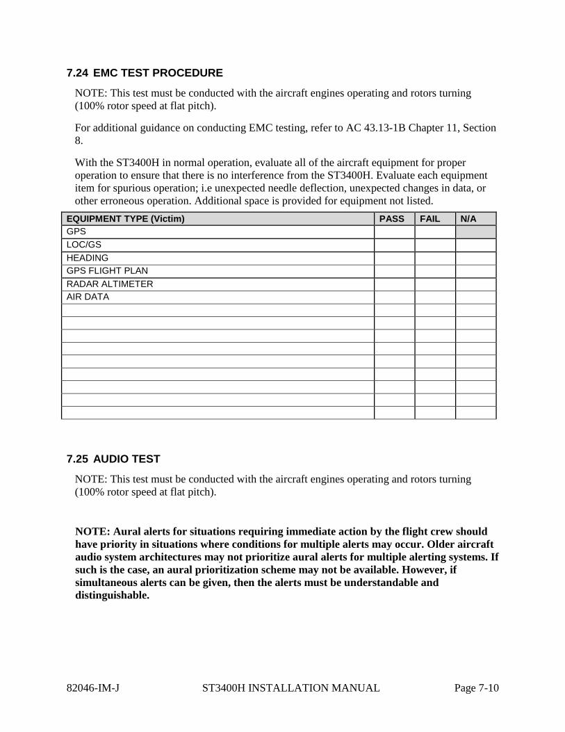
7.24 EMC TEST PROCEDURE
NOTE: This test must be conducted with the aircraft engines operating and rotors turning (100% rotor speed at flat pitch).
For additional guidance on conducting EMC testing, refer to AC 43.13-1B Chapter 11, Section 8.
With the ST3400H in normal operation, evaluate all of the aircraft equipment for proper operation to ensure that there is no interference from the ST3400H. Evaluate each equipment item for spurious operation; i.e unexpected needle deflection, unexpected changes in data, or other erroneous operation. Additional space is provided for equipment not listed.
EQUIPMENT TYPE (Victim) PASS FAIL N/A GPS LOC/GS HEADING GPS FLIGHT PLAN RADAR ALTIMETER AIR DATA
7.25 AUDIO TEST
NOTE: This test must be conducted with the aircraft engines operating and rotors turning (100% rotor speed at flat pitch).
NOTE: Aural alerts for situations requiring immediate action by the flight crew should have priority in situations where conditions for multiple alerts may occur. Older aircraft audio system architectures may not prioritize aural alerts for multiple alerting systems. If such is the case, an aural prioritization scheme may not be available. However, if simultaneous alerts can be given, then the alerts must be understandable and distinguishable.
82046-IM-J ST3400H INSTALLATION MANUAL Page 7-10
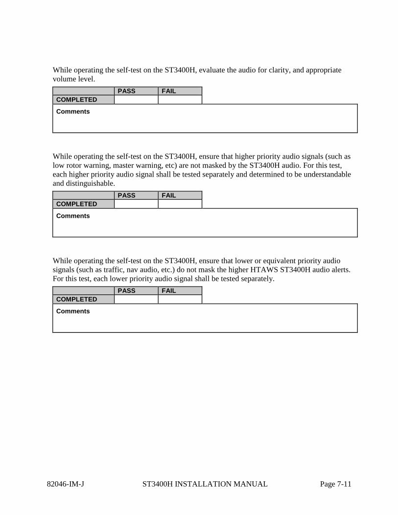
While operating the self-test on the ST3400H, evaluate the audio for clarity, and appropriate volume level.
PASS FAIL COMPLETED
Comments
While operating the self-test on the ST3400H, ensure that higher priority audio signals (such as low rotor warning, master warning, etc) are not masked by the ST3400H audio. For this test, each higher priority audio signal shall be tested separately and determined to be understandable and distinguishable.
PASS FAIL COMPLETED
Comments
While operating the self-test on the ST3400H, ensure that lower or equivalent priority audio signals (such as traffic, nav audio, etc.) do not mask the higher HTAWS ST3400H audio alerts. For this test, each lower priority audio signal shall be tested separately.
PASS FAIL COMPLETED
Comments
82046-IM-J ST3400H INSTALLATION MANUAL Page 7-11
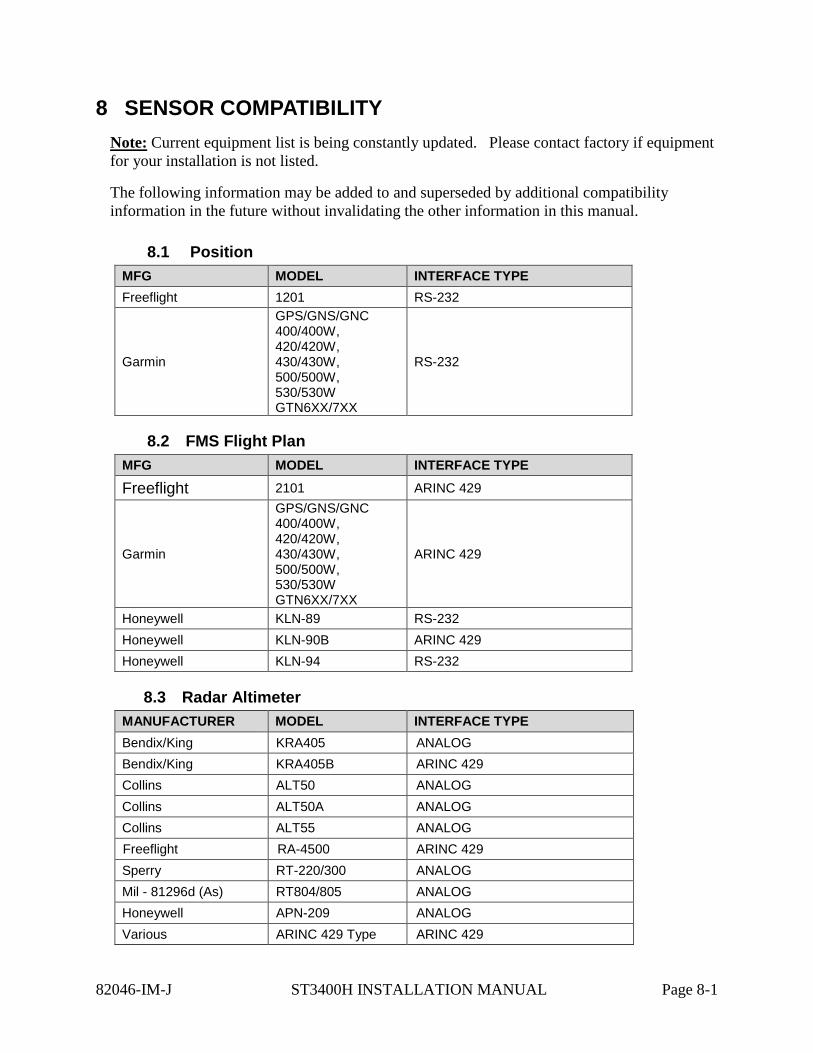
8 SENSOR COMPATIBILITY Note: Current equipment list is being constantly updated. Please contact factory if equipment for your installation is not listed.
The following information may be added to and superseded by additional compatibility information in the future without invalidating the other information in this manual.
8.1 Position MFG MODEL INTERFACE TYPE Freeflight 1201 RS-232
Garmin
GPS/GNS/GNC 400/400W, 420/420W, 430/430W, 500/500W, 530/530W GTN6XX/7XX
RS-232
8.2 FMS Flight Plan MFG MODEL INTERFACE TYPE
Freeflight 2101 ARINC 429
Garmin
GPS/GNS/GNC 400/400W, 420/420W, 430/430W, 500/500W, 530/530W GTN6XX/7XX
ARINC 429
Honeywell KLN-89 RS-232 Honeywell KLN-90B ARINC 429 Honeywell KLN-94 RS-232
8.3 Radar Altimeter MANUFACTURER MODEL INTERFACE TYPE Bendix/King KRA405 ANALOG Bendix/King KRA405B ARINC 429 Collins ALT50 ANALOG Collins ALT50A ANALOG Collins ALT55 ANALOG Freeflight RA-4500 ARINC 429 Sperry RT-220/300 ANALOG Mil - 81296d (As) RT804/805 ANALOG Honeywell APN-209 ANALOG Various ARINC 429 Type ARINC 429
82046-IM-J ST3400H INSTALLATION MANUAL Page 8-1
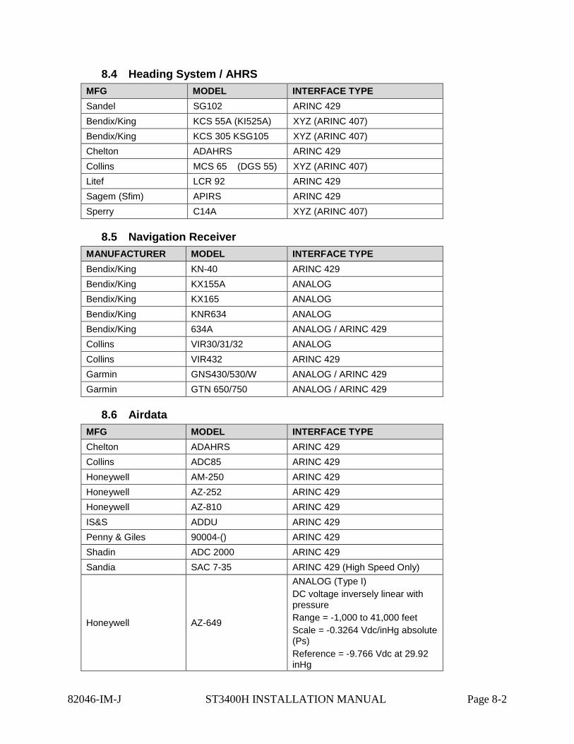
8.4 Heading System / AHRS MFG MODEL INTERFACE TYPE Sandel SG102 ARINC 429 Bendix/King KCS 55A (KI525A) XYZ (ARINC 407) Bendix/King KCS 305 KSG105 XYZ (ARINC 407) Chelton ADAHRS ARINC 429 Collins MCS 65 (DGS 55) XYZ (ARINC 407) Litef LCR 92 ARINC 429 Sagem (Sfim) APIRS ARINC 429 Sperry C14A XYZ (ARINC 407)
8.5 Navigation Receiver MANUFACTURER MODEL INTERFACE TYPE Bendix/King KN-40 ARINC 429 Bendix/King KX155A ANALOG Bendix/King KX165 ANALOG Bendix/King KNR634 ANALOG Bendix/King 634A ANALOG / ARINC 429 Collins VIR30/31/32 ANALOG Collins VIR432 ARINC 429 Garmin GNS430/530/W ANALOG / ARINC 429 Garmin GTN 650/750 ANALOG / ARINC 429
8.6 Airdata MFG MODEL INTERFACE TYPE Chelton ADAHRS ARINC 429 Collins ADC85 ARINC 429 Honeywell AM-250 ARINC 429 Honeywell AZ-252 ARINC 429 Honeywell AZ-810 ARINC 429 IS&S ADDU ARINC 429 Penny & Giles 90004-() ARINC 429 Shadin ADC 2000 ARINC 429 Sandia SAC 7-35 ARINC 429 (High Speed Only)
Honeywell AZ-649
ANALOG (Type I) DC voltage inversely linear with pressure Range = -1,000 to 41,000 feet Scale = -0.3264 Vdc/inHg absolute (Ps) Reference = -9.766 Vdc at 29.92 inHg
82046-IM-J ST3400H INSTALLATION MANUAL Page 8-2
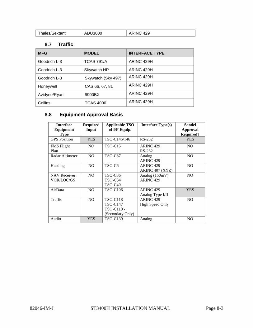
Thales/Sextant ADU3000 ARINC 429
8.7 Traffic MFG MODEL INTERFACE TYPE
Goodrich L-3 TCAS 791/A ARINC 429H
Goodrich L-3 Skywatch HP ARINC 429H
Goodrich L-3 Skywatch (Sky 497) ARINC 429H
Honeywell CAS 66, 67, 81 ARINC 429H
Avidyne/Ryan 9900BX ARINC 429H
Collins TCAS 4000 ARINC 429H
8.8 Equipment Approval Basis
Interface Equipment
Type
Required Input
Applicable TSO of I/F Equip.
Interface Type(s) Sandel Approval Required?
GPS Position YES TSO-C145/146 RS-232 YES
FMS Flight Plan
NO TSO-C15 ARINC 429 RS-232
NO
Radar Altimeter NO TSO-C87 Analog ARINC 429
NO
Heading NO TSO-C6 ARINC 429 ARINC 407 (XYZ)
NO
NAV Receiver VOR/LOC/GS
NO TSO-C36 TSO-C34 TSO-C40
Analog (150mV) ARINC 429
NO
AirData NO TSO-C106 ARINC 429 Analog Type I/II
YES
Traffic NO TSO-C118 TSO-C147 TSO-C119 - (Secondary Only)
ARINC 429 High Speed Only
NO
Audio YES TSO-C139 Analog NO
82046-IM-J ST3400H INSTALLATION MANUAL Page 8-3
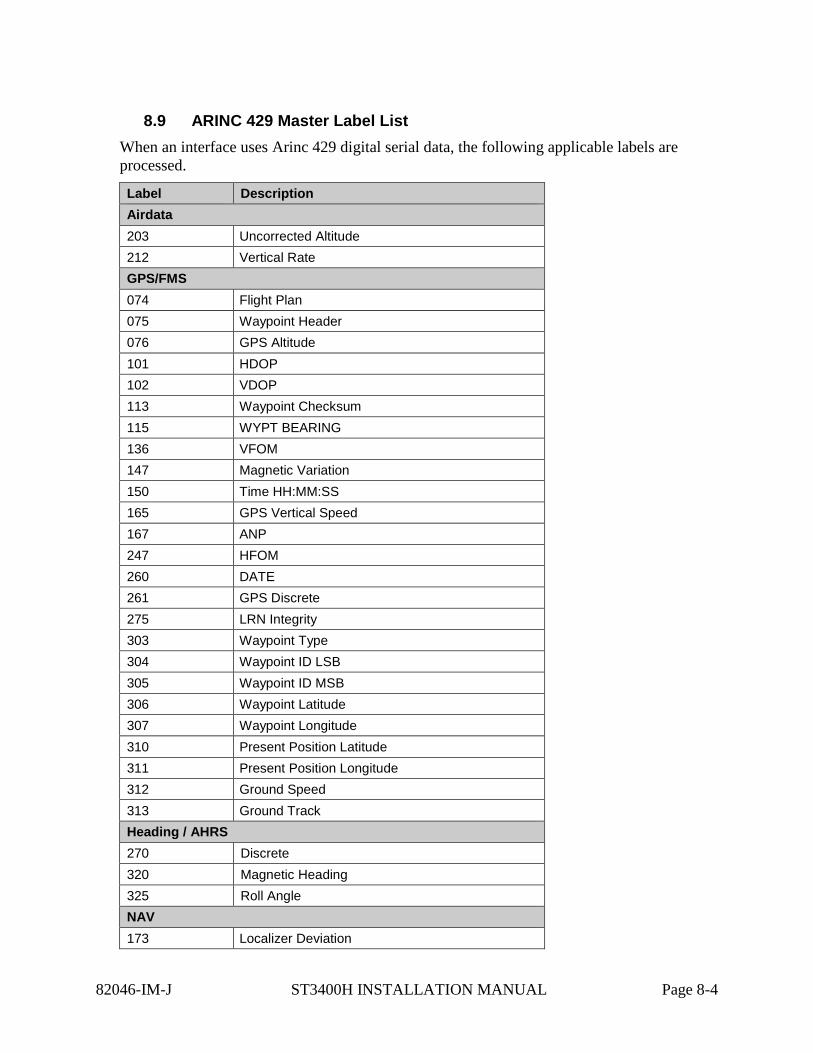
8.9 ARINC 429 Master Label List When an interface uses Arinc 429 digital serial data, the following applicable labels are processed.
Label Description Airdata 203 Uncorrected Altitude 212 Vertical Rate GPS/FMS 074 Flight Plan 075 Waypoint Header 076 GPS Altitude 101 HDOP 102 VDOP 113 Waypoint Checksum 115 WYPT BEARING 136 VFOM 147 Magnetic Variation 150 Time HH:MM:SS 165 GPS Vertical Speed 167 ANP 247 HFOM 260 DATE 261 GPS Discrete 275 LRN Integrity 303 Waypoint Type 304 Waypoint ID LSB 305 Waypoint ID MSB 306 Waypoint Latitude 307 Waypoint Longitude 310 Present Position Latitude 311 Present Position Longitude 312 Ground Speed 313 Ground Track Heading / AHRS 270 Discrete 320 Magnetic Heading 325 Roll Angle NAV 173 Localizer Deviation
82046-IM-J ST3400H INSTALLATION MANUAL Page 8-4
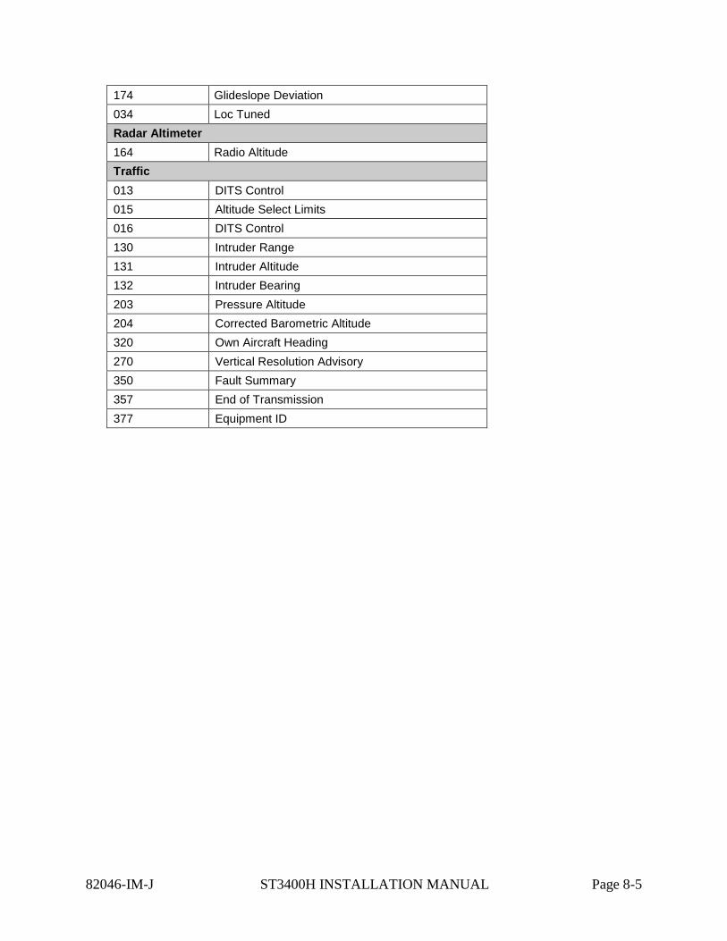
174 Glideslope Deviation 034 Loc Tuned Radar Altimeter 164 Radio Altitude Traffic 013 DITS Control 015 Altitude Select Limits 016 DITS Control 130 Intruder Range 131 Intruder Altitude 132 Intruder Bearing 203 Pressure Altitude 204 Corrected Barometric Altitude 320 Own Aircraft Heading 270 Vertical Resolution Advisory 350 Fault Summary 357 End of Transmission 377 Equipment ID
82046-IM-J ST3400H INSTALLATION MANUAL Page 8-5
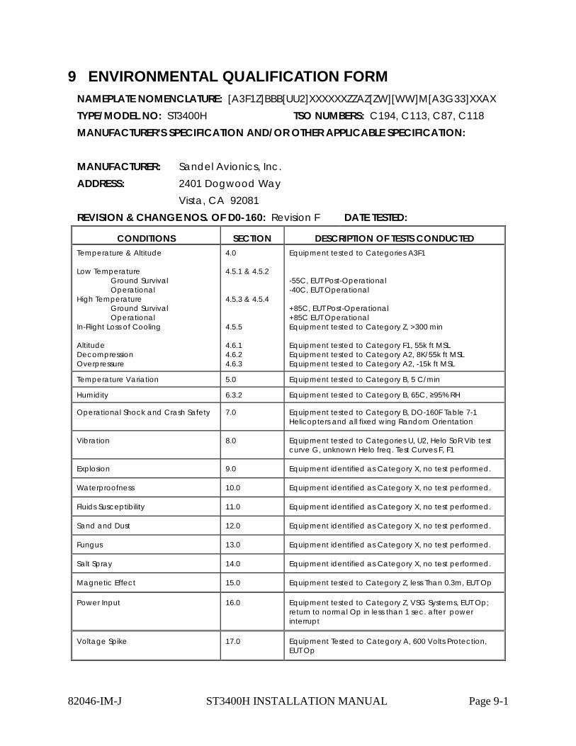
9 ENVIRONMENTAL QUALIFICATION FORM NAMEPLATE NOMENCLATURE: [A3F1Z]BBB[UU2]XXXXXXZZAZ[ZW][WW]M[A3G33]XXAX TYPE/MODEL NO: ST3400H TSO NUMBERS: C194, C113, C87, C118 MANUFACTURER’S SPECIFICATION AND/OR OTHER APPLICABLE SPECIFICATION: MANUFACTURER: Sandel Avionics, Inc. ADDRESS: 2401 Dogwood Way Vista, CA 92081 REVISION & CHANGE NOS. OF D0-160: Revision F DATE TESTED:
CONDITIONS SECTION DESCRIPTION OF TESTS CONDUCTED Temperature & Altitude Low Temperature
Ground Survival Operational
High Temperature Ground Survival Operational
In-Flight Loss of Cooling Altitude Decompression Overpressure
4.0 4.5.1 & 4.5.2 4.5.3 & 4.5.4 4.5.5 4.6.1 4.6.2 4.6.3
Equipment tested to Categories A3F1 -55C, EUT Post-Operational -40C, EUT Operational +85C, EUT Post-Operational +85C EUT Operational Equipment tested to Category Z, >300 min Equipment tested to Category F1, 55k ft MSL Equipment tested to Category A2, 8K/55k ft MSL Equipment tested to Category A2, -15k ft MSL
Temperature Variation 5.0 Equipment tested to Category B, 5 C/min
Humidity 6.3.2 Equipment tested to Category B, 65C, ≥95% RH
Operational Shock and Crash Safety 7.0 Equipment tested to Category B, DO-160F Table 7-1 Helicopters and all fixed wing Random Orientation
Vibration 8.0 Equipment tested to Categories U, U2, Helo SoR Vib test curve G, unknown Helo freq. Test Curves F, F1
Explosion 9.0 Equipment identified as Category X, no test performed.
Waterproofness 10.0 Equipment identified as Category X, no test performed.
Fluids Susceptibility 11.0 Equipment identified as Category X, no test performed.
Sand and Dust 12.0 Equipment identified as Category X, no test performed.
Fungus 13.0 Equipment identified as Category X, no test performed.
Salt Spray 14.0 Equipment identified as Category X, no test performed.
Magnetic Effect 15.0 Equipment tested to Category Z, less Than 0.3m, EUT Op
Power Input 16.0 Equipment tested to Category Z, VSG Systems, EUT Op; return to normal Op in less than 1 sec. after power interrupt
Voltage Spike 17.0 Equipment Tested to Category A, 600 Volts Protection, EUT Op
82046-IM-J ST3400H INSTALLATION MANUAL Page 9-1
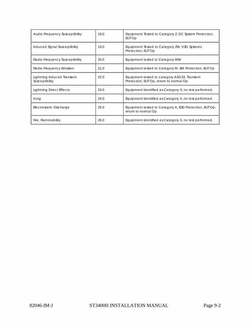
Audio Frequency Susceptibility 18.0 Equipment Tested to Category Z, DC System Protection, EUT Op
Induced Signal Susceptibility 19.0 Equipment Tested to Category ZW, VSG Systems Protection, EUT Op
Radio Frequency Susceptibility 20.0 Equipment tested to Category WW
Radio Frequency Emission 21.0 Equipment tested to Category M, EM Protection, EUT Op
Lightning Induced Transient Susceptibility
22.0 Equipment tested to category A3G33, Transient Protection, EUT Op, return to normal Op
Lightning Direct Effects 23.0 Equipment identified as Category X, no test performed.
Icing 24.0 Equipment identified as Category X, no test performed.
Electrostatic Discharge 25.0 Equipment tested to Category A, ESD Protection, EUT Op; return to normal Op
Fire, Flammability 26.0 Equipment identified as Category X, no test performed.
82046-IM-J ST3400H INSTALLATION MANUAL Page 9-2

10 SUPPLEMENTAL TYPE CERTIFICATE
10.1 STC Permission
Please contact Sandel Avionics, Inc. for permission to use these STC’s and to obtain the most recent Approved Model List (AML)
82046-IM-J ST3400H INSTALLATION MANUAL Page 10-1

10.2 Part 27 AML STC
82046-IM-J ST3400H INSTALLATION MANUAL Page 10-2
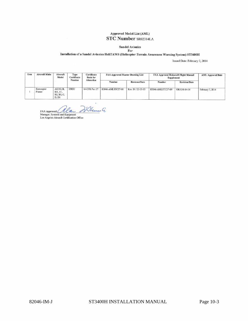
82046-IM-J ST3400H INSTALLATION MANUAL Page 10-3

82046-IM-J ST3400H INSTALLATION MANUAL Page 10-4

82046-IM-J ST3400H INSTALLATION MANUAL Page 10-5

10.3 Part 29 AML STC
82046-IM-J ST3400H INSTALLATION MANUAL Page 10-6
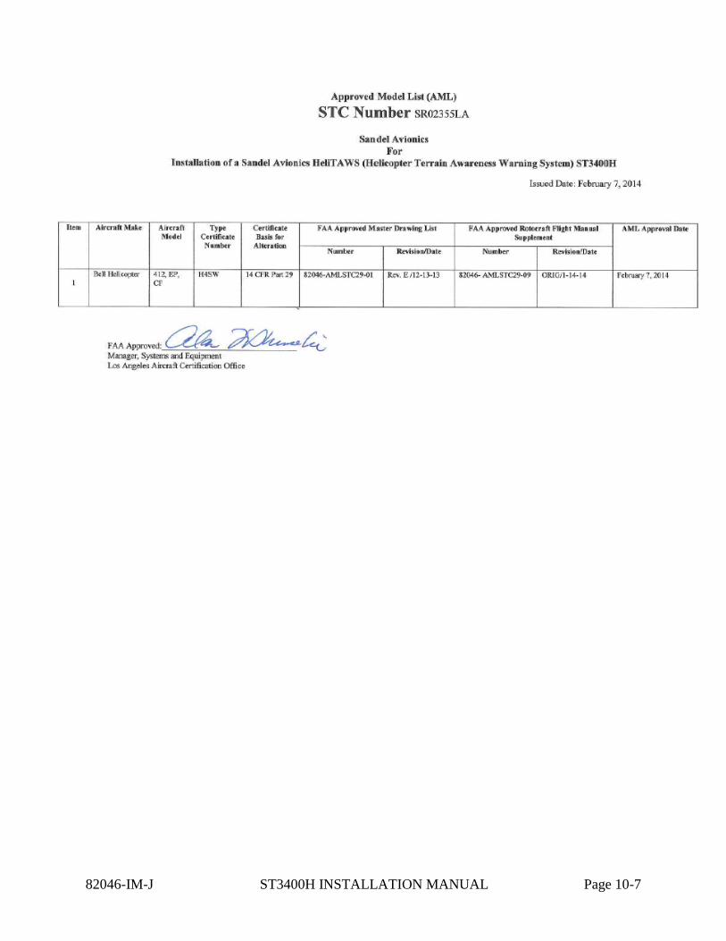
82046-IM-J ST3400H INSTALLATION MANUAL Page 10-7

82046-IM-J ST3400H INSTALLATION MANUAL Page 10-8

82046-IM-J ST3400H INSTALLATION MANUAL Page 10-9

11 INSTRUCTIONS FOR CONTINUED AIRWORTHINESS The instructions contained in this section are for general reference. The FAA AEG accepted Instructions for Continued Airworthiness are contained in the STC data package (reference Sandel document 82046-STC27-05). Normal maintenance activities performed on the ST3400H should follow standard industry practices. Re-programming the Configuration Module and updating the Databases, are addressed in specific sections of this installation manual.
11.1 Periodic Maintenance
The ST3400H is designed to detect internal failures. A thorough self-test is executed automatically upon application of power to the unit, and Built-In-Test (BIT) is continuously executed. Detected errors are indicated on the equipment via failure messages and maintenance is on-condition. Operation of the ST3400H is not permitted unless an inspection as described in this section has been completed within the preceding 12 calendar months. Conduct a visual inspection on the ST3400H and its wire harness to insure installation integrity:
• Inspect the unit for security of attachment. • Inspect buttons for legibility. • Inspect condition of wiring, routing and attachment/clamping. • Inspect knob operation. • Inspect front panel and clean as necessary
11.2 Cleaning the Front Panel
The front bezel, keypad, and display can be cleaned with a soft cotton cloth dampened with “Edmund Scientific TECH SPEC Lens Cleaner” or equivalent. Care should be taken to avoid scratching the surface of the display.
11.3 Display Light Source
The display light source is rated by the manufacturer as having a usable life of 80,000 hours. This life may be more or less than the rated time depending on the operating conditions of the ST3400H. Over time, the light source may dim and the display may not perform as well in direct sunlight conditions. The user must determine by observation when the display brightness is not suitable for its intended use. Contact the Sandel Customer Service if the light source requires service.
11.4 Trouble Shooting Information
If the ST3400H fails to properly operate, consult a local authorized Sandel dealer for repair. The ST3400H does not contain any user serviceable components.
82046-IM-J ST3400H INSTALLATION MANUAL Page 11-1
11.5 Removal and Replacement
If the ST3400H is removed for repair and reinstalled, or removed and replaced with a different ST3400H, follow Post Installation Configuration and Checkout Procedures contained in the manual.
If any work has been done on the aircraft that could affect the system wiring or interconnected equipment, verify the ST3400H operates properly, follow the Post Installation Configuration and Checkout Procedures contained in this manual.
To remove the ST3400H from the mounting clamp, use a standard #2 Philips screwdriver to loosen the clamping screws until the ST3400H can be freely pulled from the panel.
The ST3400H is installed by connecting the three (3) cable harnesses and then sliding it straight in the clamping mechanism until the front bezel meets the aircraft instrument panel. Tighten all four (4) clamp screws.
11.6 Database Updates
Database updates are not required. Information regarding new database releases and the content details of the databases may be obtained by visiting the Sandel website ( www.sandel.com ). Database updates may be ordered on-line. It is up to the ST3400H customer to determine if a specific database is applicable to their operations.
11.7 Software Updates
Software updates are released via a Service Information Letter (SIL) or a Service Bulletin (SB). The SIL or SB will contain links to the software and the related software installation files and instructions necessary to perform the update. Software updates must be performed by a Sandel authorized dealer or repair station.
It is the user/owners responsibility to periodically check for SIL’s and or SB’s relating to the ST3400H. SIL’s and SB’s can be found at: www.sandel.com under “Support”.
82046-IM-J ST3400H INSTALLATION MANUAL Page 11-2
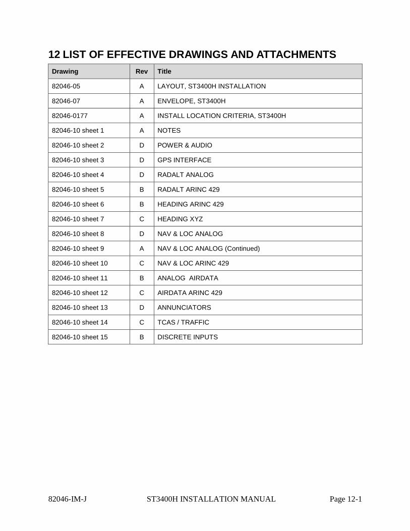
12 LIST OF EFFECTIVE DRAWINGS AND ATTACHMENTS Drawing Rev Title
82046-05 A LAYOUT, ST3400H INSTALLATION
82046-07 A ENVELOPE, ST3400H
82046-0177 A INSTALL LOCATION CRITERIA, ST3400H
82046-10 sheet 1 A NOTES
82046-10 sheet 2 D POWER & AUDIO
82046-10 sheet 3 D GPS INTERFACE
82046-10 sheet 4 D RADALT ANALOG
82046-10 sheet 5 B RADALT ARINC 429
82046-10 sheet 6 B HEADING ARINC 429
82046-10 sheet 7 C HEADING XYZ
82046-10 sheet 8 D NAV & LOC ANALOG
82046-10 sheet 9 A NAV & LOC ANALOG (Continued)
82046-10 sheet 10 C NAV & LOC ARINC 429
82046-10 sheet 11 B ANALOG AIRDATA
82046-10 sheet 12 C AIRDATA ARINC 429
82046-10 sheet 13 D ANNUNCIATORS
82046-10 sheet 14 C TCAS / TRAFFIC
82046-10 sheet 15 B DISCRETE INPUTS
82046-IM-J ST3400H INSTALLATION MANUAL Page 12-1
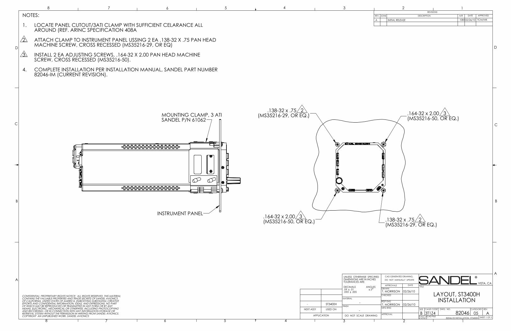
.138-32 x .75 2(MS35216-29, OR EQ.)
.138-32 x .75 2(MS35216-29, OR EQ.)
.164-32 x 2.00 3(MS35216-50, OR EQ.)
.164-32 x 2.00 3(MS35216-50, OR EQ.)
MOUNTING CLAMP, 3 ATISANDEL P/N 61062
INSTRUMENT PANEL
D
C
B
AA
B
C
D
CAD GENERATED DRAWING,DO NOT MANUALLY UPDATE
SCALE 1:2& NOTED
SIZE CAGE CODE
BSHEET 1 OF 2
REV.
LAYOUT, ST3400HINSTALLATION
DATEAPPROVALSDRAWN
CHECKED
RESP ENG
MFG ENG
APPROVAL
UNLESS OTHERWISE SPECIFIEDDIMENSIONS ARE IN INCHESTOLERANCES ARE:
DECIMALS ANGLES.XX .01 .5.XXX .005
MATERIAL
FINISH-
DO NOT SCALE DRAWINGAPPLICATION
USED ONNEXT ASSY
12345678
8 7 6 5 4 3 2 1REVISIONS
REV. DESCRIPTION APPROVED
VISTA, CA
A82046
T. MORRISON
DWG. NO.
3T1Z4-
NOTES:
LOCATE PANEL CUTOUT/3ATI CLAMP WITH SUFFICIENT CELARANCE ALL 1.AROUND (REF. ARINC SPECIFICATION 408A
ATTACH CLAMP TO INSTRUMENT PANEL USSING 2 EA .138-32 X .75 PAN HEAD 2.MACHINE SCREW, CROSS RECESSED (MS35216-29, OR EQ)
INSTALL 2 EA ADJUSTING SCREWS, .164-32 X 2.00 PAN HEAD MACHINE 3.SCREW, CROSS RECESSED (MS35216-50).
COMPLETE INSTALLATION PER INSTALLATION MANUAL, SANDEL PART NUMBER 4.82046-IM (CURRENT REVISION).
T. MORRISON
02/26/10
02/26/10
82046-05 INSTALLATION, ST3400H
CONFIDENTIAL: PROPRIETARY RIGHTS NOTICE: ALL RIGHTS RESERVED. THIS MATERIALCONTAINS THE VALUABLE PROPERTIES AND TRADE SECRETS OF SANDEL AVIONICSOF CALIFORNIA, UNITED STATES OF AMERICA, EMBODYING SUBSTANTIAL CREATIVEEFFORTS AND CONFIDENTIAL INFORMATION, IDEAS, AND EXPRESSIONS, NO PARTOF WHICH MAY BE REPRODUCED OR TRANSMITTED IN ANY FORM OR BY ANYMEANS, ELECTRONIC, MECHANICAL OR OTHERWISE, INCLUDING PHOTOCOPYINGAND RECORDING, OR IN CONNECTION WITH ANY INFORMATION STORAGE ORRETRIEVAL SYSTEM WITHOUT THE PERMISSION IN WRITING FROM SANDEL AVIONICS.COPYRIGHT AN UNPUBLISHED WORK. SANDEL AVIONICS CAD FILE
-
INITIAL RELEASEA
ZONE
ST3400H
TCM/MK 02/26/10
CATEGORY
05
DATEA/R
1085
TITLE
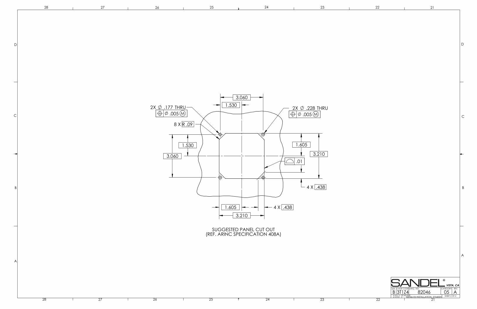
3.210
8 X R .09
3.210
2X .228 THRU2X .177 THRU
3.060
3.060
1.605
1.605
4 X .438
4 X .438
1.530
1.530
SUGGESTED PANEL CUT OUT(REF. ARINC SPECIFICATION 408A)
.005 M
.01
.005 M
D
C
B
AA
B
C
D
SCALE 1:2& NOTED
SIZE CAGE CODE
BREV.
2122232425262728
28 27 26 25 24 23 22 21
VISTA, CA
82046 ADWG. NO.
3T1Z4SHEET 2 OF 2CAD FILE:
82046-05 INSTALLATION, ST3400H
05CATEGORY
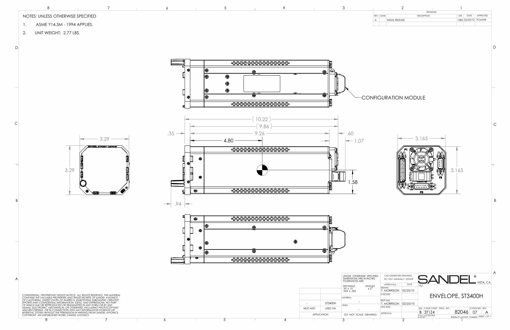
3.29
3.29
9.269.86
.35 .60
10.22
.94
1.074.80
1.58
3.165
3.165
CONFIGURATION MODULE
D
C
B
AA
B
C
D
CAD GENERATED DRAWING,DO NOT MANUALLY UPDATE
SCALE 1:2& NOTED
SIZE CAGE CODE
BSHEET 1 OF 1
REV.
ENVELOPE, ST3400H
DATEAPPROVALSDRAWN
CHECKED
RESP ENG
MFG ENG
APPROVAL
UNLESS OTHERWISE SPECIFIEDDIMENSIONS ARE IN INCHESTOLERANCES ARE:
DECIMALS ANGLES.XX .01 .5.XXX .005
MATERIAL
FINISH-
DO NOT SCALE DRAWINGAPPLICATION
USED ONNEXT ASSY
12345678
8 7 6 5 4 3 2 1REVISIONS
REV. DESCRIPTION APPROVED
VISTA, CA
A82046
T. MORRISON
DWG. NO.
3T1Z4-
T. MORRISON
02/25/10
02/25/10
82046-07 LAYOUT, ST3400H
CONFIDENTIAL: PROPRIETARY RIGHTS NOTICE: ALL RIGHTS RESERVED. THIS MATERIALCONTAINS THE VALUABLE PROPERTIES AND TRADE SECRETS OF SANDEL AVIONICSOF CALIFORNIA, UNITED STATES OF AMERICA, EMBODYING SUBSTANTIAL CREATIVEEFFORTS AND CONFIDENTIAL INFORMATION, IDEAS, AND EXPRESSIONS, NO PARTOF WHICH MAY BE REPRODUCED OR TRANSMITTED IN ANY FORM OR BY ANYMEANS, ELECTRONIC, MECHANICAL OR OTHERWISE, INCLUDING PHOTOCOPYINGAND RECORDING, OR IN CONNECTION WITH ANY INFORMATION STORAGE ORRETRIEVAL SYSTEM WITHOUT THE PERMISSION IN WRITING FROM SANDEL AVIONICS.COPYRIGHT AN UNPUBLISHED WORK. SANDEL AVIONICS CAD FILE
-
INITIAL RELEASEA
ZONE
ST3400H
TCM/MK 02/25/10
CATEGORY
07
DATEA/R
1085
TITLE
NOTES: UNLESS OTHERWISE SPECIFIED
ASME Y14.5M - 1994 APPLIES.1.
UNIT WEIGHT: 2.77 LBS.2.
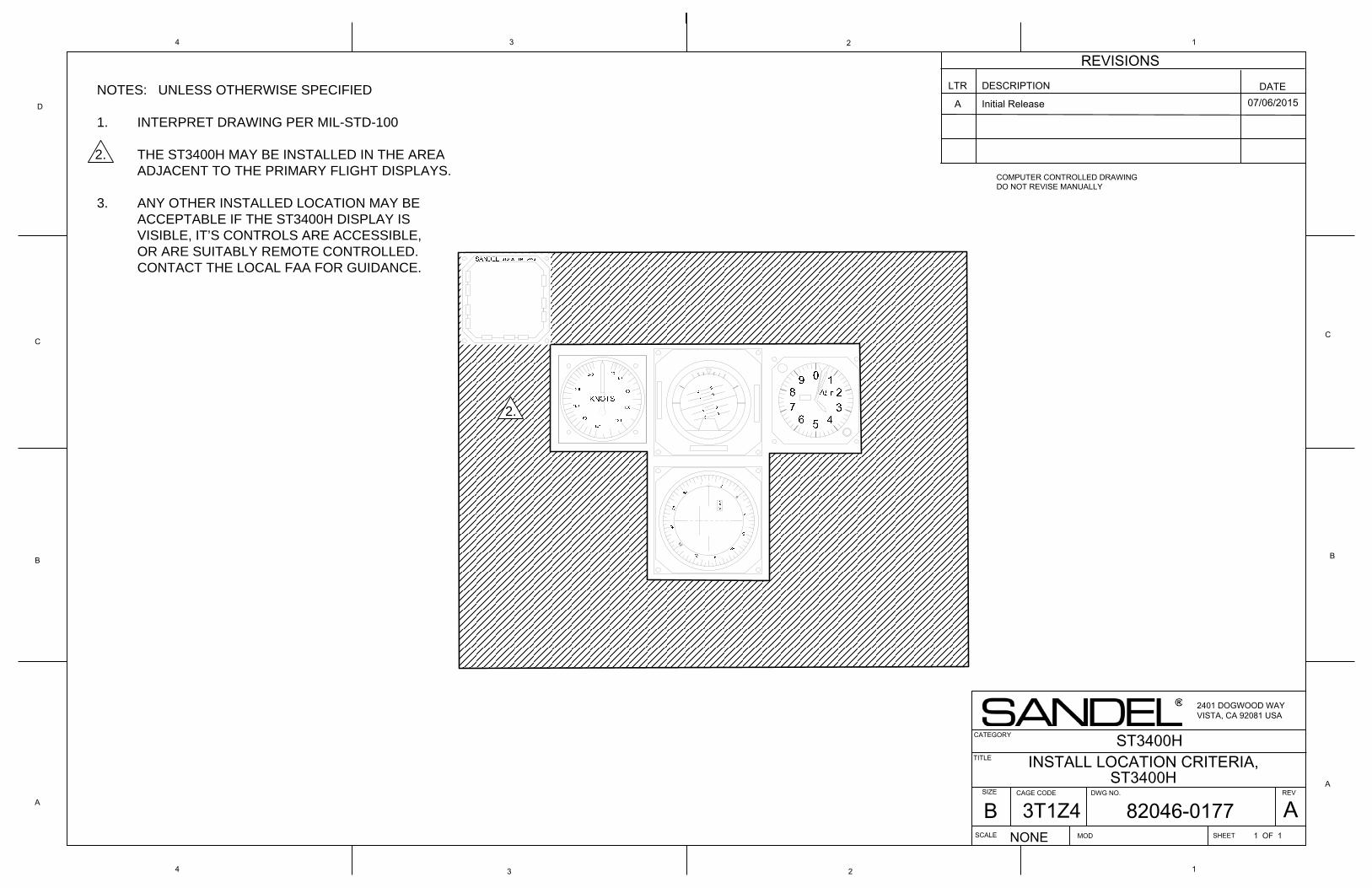
4 3 2
A
B
C
134
D
C
B
A
1
COMPUTER CONTROLLED DRAWINGDO NOT REVISE MANUALLY
2
NOTES: UNLESS OTHERWISE SPECIFIED
1. INTERPRET DRAWING PER MIL-STD-100
THE ST3400H MAY BE INSTALLED IN THE AREAADJACENT TO THE PRIMARY FLIGHT DISPLAYS.
3. ANY OTHER INSTALLED LOCATION MAY BE ACCEPTABLE IF THE ST3400H DISPLAY IS VISIBLE, IT’S CONTROLS ARE ACCESSIBLE, OR ARE SUITABLY REMOTE CONTROLLED.CONTACT THE LOCAL FAA FOR GUIDANCE.
LTR DESCRIPTION DATEA Initial Release 07/06/2015
REVISIONS
TITLE
SIZE DWG NO.
SCALE SHEET
REV
NONE
2401 DOGWOOD WAYVISTA, CA 92081 USA
CAGE CODE
ST3400H
MOD 1 OF 1
CATEGORY
2.
24
6
2.
INSTALL LOCATION CRITERIA, ST3400H
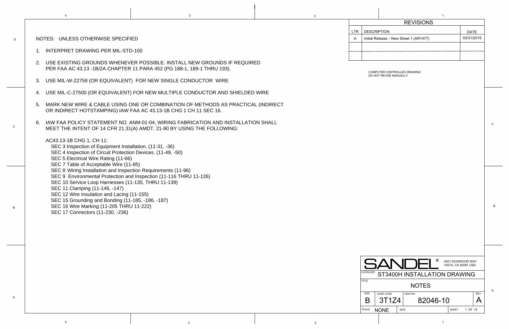
4 3 2
A
B
C
134
D
C
B
A
1
COMPUTER CONTROLLED DRAWINGDO NOT REVISE MANUALLY
2
NOTES: UNLESS OTHERWISE SPECIFIED
1. INTERPRET DRAWING PER MIL-STD-100
2. USE EXISTING GROUNDS WHENEVER POSSIBLE. INSTALL NEW GROUNDS IF REQUIRED PER FAA AC 43.13 -1B/2A CHAPTER 11 PARA 452 (PG 188-1, 189-1 THRU 193).
3. USE MIL-W-22759 (OR EQUIVALENT) FOR NEW SINGLE CONDUCTOR WIRE
4. USE MIL-C-27500 (OR EQUIVALENT) FOR NEW MULTIPLE CONDUCTOR AND SHIELDED WIRE
5. MARK NEW WIRE & CABLE USING ONE OR COMBINATION OF METHODS AS PRACTICAL (INDIRECT OR INDIRECT HOTSTAMPING) IAW FAA AC 43.13-1B CHG 1 CH 11 SEC 16.
6. IAW FAA POLICY STATEMENT NO. ANM-01-04, WIRING FABRICATION AND INSTALLATION SHALL MEET THE INTENT OF 14 CFR 21.31(A) AMDT. 21-90 BY USING THE FOLLOWING:
AC43.13-1B CHG 1, CH 11:SEC 3 Inspection of Equipment Installation, (11-31, -36)SEC 4 Inspection of Circuit Protection Devices. (11-49, -50)SEC 5 Electrical Wire Rating (11-66)SEC 7 Table of Acceptable Wire (11-85)SEC 8 Wiring Installation and Inspection Requirements (11-96)SEC 9 Environmental Protection and Inspection (11-116 THRU 11-126)SEC 10 Service Loop Harnesses (11-135, THRU 11-139)SEC 11 Clamping (11-146, -147)SEC 12 Wire Insulation and Lacing (11-155)SEC 15 Grounding and Bonding (11-185, -186, -187)SEC 16 Wire Marking (11-205 THRU 11-222)SEC 17 Connectors (11-230, -236)
LTR DESCRIPTION DATEA Initial Release – New Sheet 1 (AR1477) 03/31/2015
REVISIONS
TITLE
SIZE DWG NO.
SCALE SHEET
REV
NONE
2401 DOGWOOD WAYVISTA, CA 92081 USA
CAGE CODE
ST3400H INSTALLATION DRAWING
MOD 1 OF 15
CATEGORY
NOTES
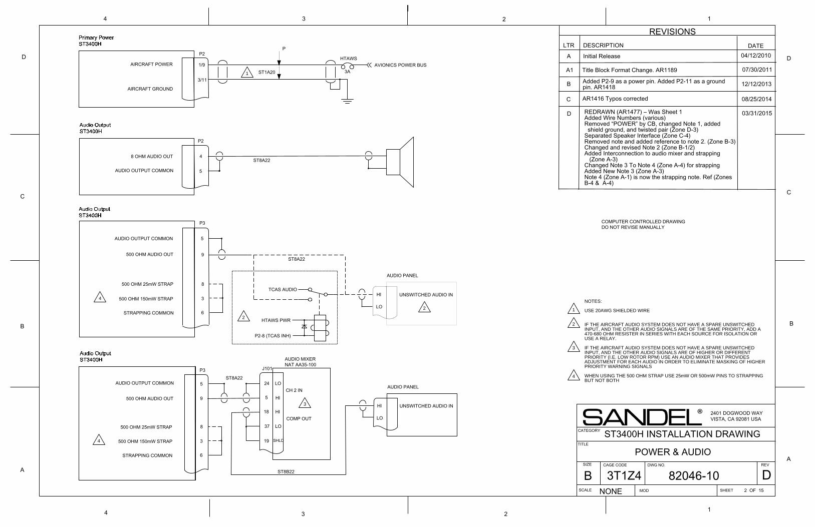
4 3 2
REVISIONSLTR DESCRIPTION DATE
TITLE
SIZE DWG NO.
SCALE SHEET
REVA
B
C
D
134
D
C
B
A
1
NONE
A
2401 DOGWOOD WAYVISTA, CA 92081 USA
CAGE CODE
2
Initial Release
ST3400H INSTALLATION DRAWING
AVIONICS POWER BUS
P2
AIRCRAFT POWER
AIRCRAFT GROUND
1/9
3/11
HTAWS
3A
UNSWITCHED AUDIO IN
HTAWS PWR
P2-8 (TCAS INH)
AUDIO PANEL
TCAS AUDIO
04/12/2010
MOD 2 OF 15
COMPUTER CONTROLLED DRAWINGDO NOT REVISE MANUALLY
9500 OHM AUDIO OUT
P3
AUDIO OUTPUT COMMON 5
AUDIO MIXERNAT AA35-100
J101
UNSWITCHED AUDIO IN
AUDIO PANEL
5
24
HI
LOCH 2 IN
18 HI
37 LO
SHLD19
COMP OUT8
3
6
500 OHM 25mW STRAP
500 OHM 150mW STRAP
STRAPPING COMMON
P3
5AUDIO OUTPUT COMMON
9
P2
5AUDIO OUTPUT COMMON
8 OHM AUDIO OUT 4
A1 Title Block Format Change. AR1189 07/30/2011
B Added P2-9 as a power pin. Added P2-11 as a ground pin. AR1418 12/12/2013
D REDRAWN (AR1477) – Was Sheet 1Added Wire Numbers (various)Removed “POWER” by CB, changed Note 1, added shield ground, and twisted pair (Zone D-3)Separated Speaker Interface (Zone C-4)Removed note and added reference to note 2. (Zone B-3)Changed and revised Note 2 (Zone B-1/2) Added Interconnection to audio mixer and strapping (Zone A-3)Changed Note 3 To Note 4 (Zone A-4) for strappingAdded New Note 3 (Zone A-3)Note 4 (Zone A-1) is now the strapping note. Ref (Zones B-4 & A-4)
03/31/2015
2
3
4
CATEGORY
POWER & AUDIO
ST1A201
ST8A22
ST8A22
ST8B22
HI
LO
HI
LO
P
ST8A22
500 OHM AUDIO OUT
2
8
3
6
500 OHM 25mW STRAP
500 OHM 150mW STRAP
STRAPPING COMMON
4
C 08/25/2014AR1416 Typos corrected
1
NOTES:
USE 20AWG SHIELDED WIRE
IF THE AIRCRAFT AUDIO SYSTEM DOES NOT HAVE A SPARE UNSWITCHED INPUT, AND THE OTHER AUDIO SIGNALS ARE OF THE SAME PRIORITY, ADD A 470-680 OHM RESISTER IN SERIES WITH EACH SOURCE FOR ISOLATION OR USE A RELAY.
IF THE AIRCRAFT AUDIO SYSTEM DOES NOT HAVE A SPARE UNSWITCHED INPUT, AND THE OTHER AUDIO SIGNALS ARE OF HIGHER OR DIFFERENT PRIORITY (I.E. LOW ROTOR RPM) USE AN AUDIO MIXER THAT PROVIDES ADJUSTMENT FOR EACH AUDIO IN ORDER TO ELIMINATE MASKING OF HIGHER PRIORITY WARNING SIGNALS
WHEN USING THE 500 OHM STRAP USE 25mW OR 500mW PINS TO STRAPPING BUT NOT BOTH
2
3
4
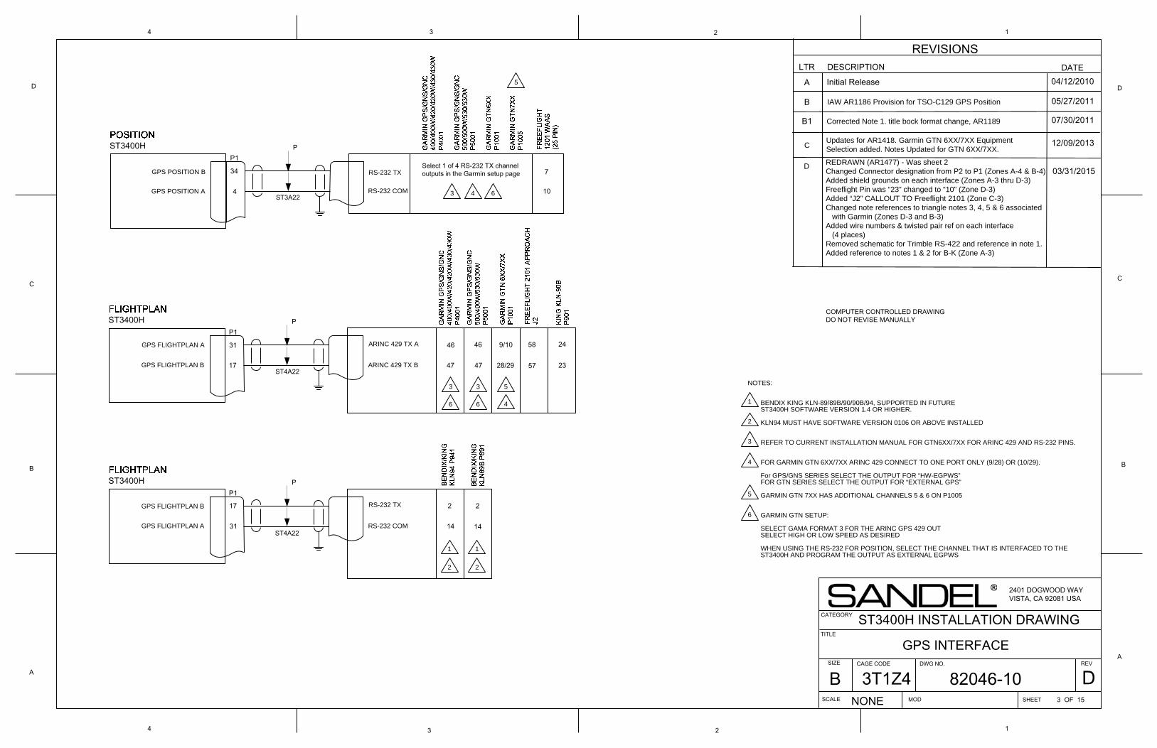
4 3 2
A
B
C
D
134
D
C
B
A
1
COMPUTER CONTROLLED DRAWINGDO NOT REVISE MANUALLY
2
REVISIONSLTR DESCRIPTION DATE
A Initial Release 04/12/2010
B
TITLE
SIZE DWG NO.
SCALE SHEET
REV
NONE
2401 DOGWOOD WAYVISTA, CA 92081 USA
CAGE CODE
ST3400H INSTALLATION DRAWING
MOD 3 OF 15
CATEGORY
GPS INTERFACE
ST3400HP1
34
4
GPS POSITION B
GPS POSITION A
RS-232 TX
RS-232 COM
P
Select 1 of 4 RS-232 TX channel outputs in the Garmin setup page 7
10
ST3400HP1
31
17GPS FLIGHTPLAN B
GPS FLIGHTPLAN A ARINC 429 TX A
P
46
47ARINC 429 TX B
46
47
9/10
28/29
58
57
24
23
ST3400HP1
31
17GPS FLIGHTPLAN B
GPS FLIGHTPLAN A
RS-232 TX
P
2
14RS-232 COM
2
14
ST3A22
ST4A22
ST4A22
IAW AR1186 Provision for TSO-C129 GPS Position 05/27/2011
B1 Corrected Note 1. title bock format change, AR1189 07/30/2011
C Updates for AR1418. Garmin GTN 6XX/7XX Equipment Selection added. Notes Updated for GTN 6XX/7XX.
REDRAWN (AR1477) - Was sheet 2Changed Connector designation from P2 to P1 (Zones A-4 & B-4)Added shield grounds on each interface (Zones A-3 thru D-3)Freeflight Pin was “23” changed to “10” (Zone D-3)Added “J2” CALLOUT TO Freeflight 2101 (Zone C-3)Changed note references to triangle notes 3, 4, 5 & 6 associated with Garmin (Zones D-3 and B-3)Added wire numbers & twisted pair ref on each interface (4 places)Removed schematic for Trimble RS-422 and reference in note 1.Added reference to notes 1 & 2 for B-K (Zone A-3)
D
12/09/2013
03/31/2015
4
2
3
3
5
5
6
6
1
3
6
2
1
4
NOTES:
BENDIX KING KLN-89/89B/90/90B/94, SUPPORTED IN FUTURE ST3400H SOFTWARE VERSION 1.4 OR HIGHER.
KLN94 MUST HAVE SOFTWARE VERSION 0106 OR ABOVE INSTALLED
REFER TO CURRENT INSTALLATION MANUAL FOR GTN6XX/7XX FOR ARINC 429 AND RS-232 PINS.
FOR GARMIN GTN 6XX/7XX ARINC 429 CONNECT TO ONE PORT ONLY (9/28) OR (10/29).
For GPS/GNS SERIES SELECT THE OUTPUT FOR “HW-EGPWS” FOR GTN SERIES SELECT THE OUTPUT FOR “EXTERNAL GPS”
GARMIN GTN 7XX HAS ADDITIONAL CHANNELS 5 & 6 ON P1005
GARMIN GTN SETUP:
SELECT GAMA FORMAT 3 FOR THE ARINC GPS 429 OUT SELECT HIGH OR LOW SPEED AS DESIRED
WHEN USING THE RS-232 FOR POSITION, SELECT THE CHANNEL THAT IS INTERFACED TO THE ST3400H AND PROGRAM THE OUTPUT AS EXTERNAL EGPWS
4
2
3
5
6
1
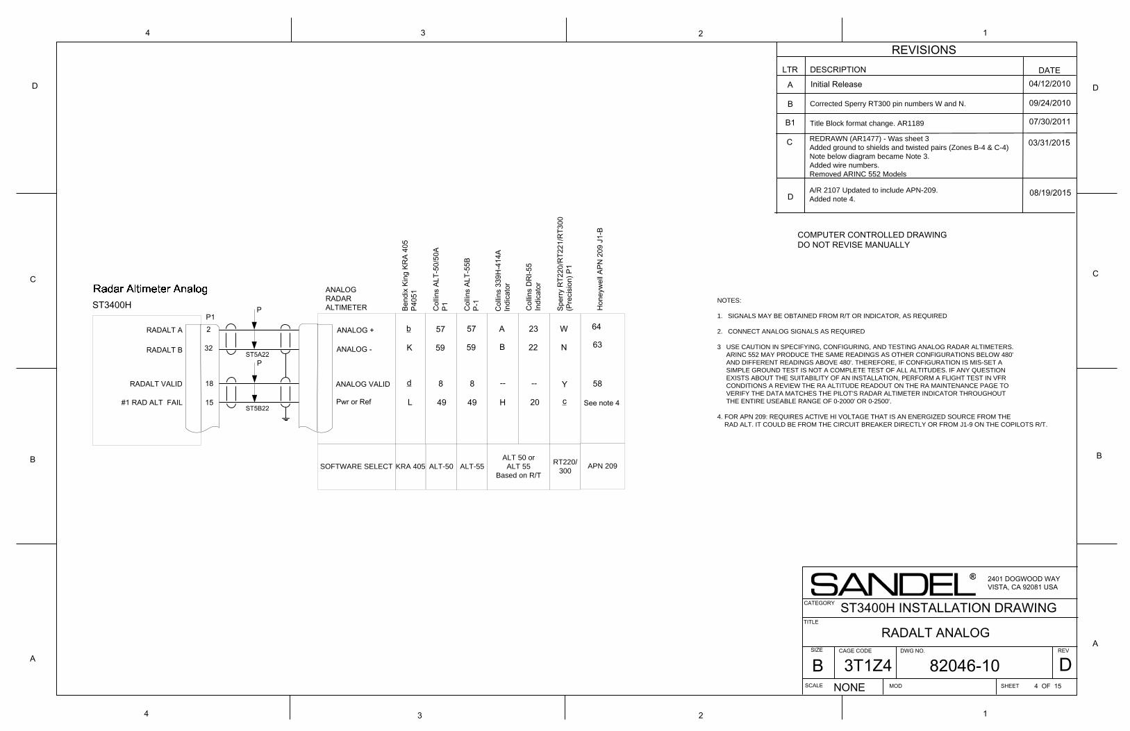
4 3 2
A
B
C
D
134
D
C
B
A
1
COMPUTER CONTROLLED DRAWINGDO NOT REVISE MANUALLY
2
RADALT B
RADALT A
15#1 RAD ALT FAIL Pwr or Ref
ST3400H
18RADALT VALID
ANALOGRADARALTIMETER
ANALOG -
ANALOG VALID
ANALOG +2
32
P1
NOTES:
1. SIGNALS MAY BE OBTAINED FROM R/T OR INDICATOR, AS REQUIRED
2. CONNECT ANALOG SIGNALS AS REQUIRED
3 USE CAUTION IN SPECIFYING, CONFIGURING, AND TESTING ANALOG RADAR ALTIMETERS. ARINC 552 MAY PRODUCE THE SAME READINGS AS OTHER CONFIGURATIONS BELOW 480' AND DIFFERENT READINGS ABOVE 480'. THEREFORE, IF CONFIGURATION IS MIS-SET A SIMPLE GROUND TEST IS NOT A COMPLETE TEST OF ALL ALTITUDES. IF ANY QUESTION EXISTS ABOUT THE SUITABILITY OF AN INSTALLATION, PERFORM A FLIGHT TEST IN VFR CONDITIONS A REVIEW THE RA ALTITUDE READOUT ON THE RA MAINTENANCE PAGE TO VERIFY THE DATA MATCHES THE PILOT’S RADAR ALTIMETER INDICATOR THROUGHOUT THE ENTIRE USEABLE RANGE OF 0-2000' OR 0-2500'.
4. FOR APN 209: REQUIRES ACTIVE HI VOLTAGE THAT IS AN ENERGIZED SOURCE FROM THE RAD ALT. IT COULD BE FROM THE CIRCUIT BREAKER DIRECTLY OR FROM J1-9 ON THE COPILOTS R/T.
LTR DESCRIPTION DATEA Initial Release 04/12/2010
B 09/24/2010
B1 07/30/2011
REDRAWN (AR1477) - Was sheet 3Added ground to shields and twisted pairs (Zones B-4 & C-4)Note below diagram became Note 3.Added wire numbers.Removed ARINC 552 Models
03/31/2015
TITLE
SIZE DWG NO.
SCALE SHEET
REV
NONE
2401 DOGWOOD WAYVISTA, CA 92081 USA
CAGE CODE
ST3400H INSTALLATION DRAWING
MOD 4 OF 15
CATEGORY
RADALT ANALOG
REVISIONS
Corrected Sperry RT300 pin numbers W and N.
Title Block format change. AR1189
C
SOFTWARE SELECT KRA 405
L
d
b
K
Bend
ix K
ing
KRA
405
P405
1
ALT-50
49
8
57
59
Col
lins
ALT-
50/5
0AP1
ALT-55
49
8
57
59
Col
lins
339H
-414
AIn
dica
tor
H
--
A
B
Col
lins
ALT-
55B
P-1
20
--
23
22
Col
lins
DR
I-55
Indi
cato
r
ALT 50 orALT 55
Based on R/T
RT220/300
c
Y
W
N
Sper
ry R
T220
/RT2
21/R
T300
(Pre
cisi
on) P
1
P
PST5A22
ST5B22
APN 209
Hon
eyw
ell A
PN 2
09 J
1-B
D
64
63
58
See note 4
A/R 2107 Updated to include APN-209.Added note 4.
08/19/2015
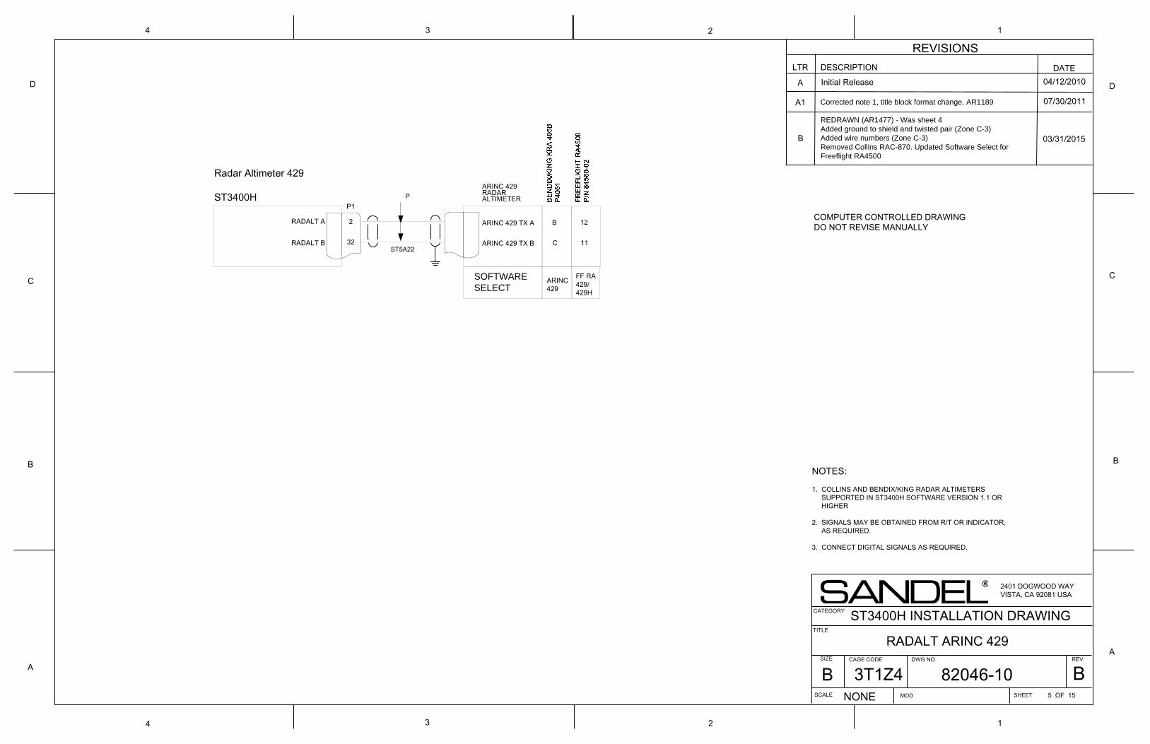
RADALT A
RADALT B
P1
32
2 ARINC 429 TX A
ARINC 429 TX B
ARINC 429RADARALTIMETER
NOTES:
1. COLLINS AND BENDIX/KING RADAR ALTIMETERS SUPPORTED IN ST3400H SOFTWARE VERSION 1.1 OR HIGHER
2. SIGNALS MAY BE OBTAINED FROM R/T OR INDICATOR, AS REQUIRED.
3. CONNECT DIGITAL SIGNALS AS REQUIRED.
Radar Altimeter 429
ST3400H P
A
B
C
D
134
D
C
B
A
1
COMPUTER CONTROLLED DRAWINGDO NOT REVISE MANUALLY
2
4 3 2
TITLE
SIZE DWG NO.
SCALE SHEET
REV
NONE
2401 DOGWOOD WAYVISTA, CA 92081 USA
CAGE CODE
ST3400H INSTALLATION DRAWING
MOD 5 OF 15
CATEGORY
RADALT ARINC 429
LTR DESCRIPTION DATEA Initial Release 04/12/2010
A1 07/30/2011
REDRAWN (AR1477) - Was sheet 4Added ground to shield and twisted pair (Zone C-3)Added wire numbers (Zone C-3)Removed Collins RAC-870. Updated Software Select for Freeflight RA4500
03/31/2015
REVISIONS
Corrected note 1, title block format change. AR1189
B
SOFTWARE SELECT
C
B
11
12
ARINC 429
ST5A22
FF RA 429/429H
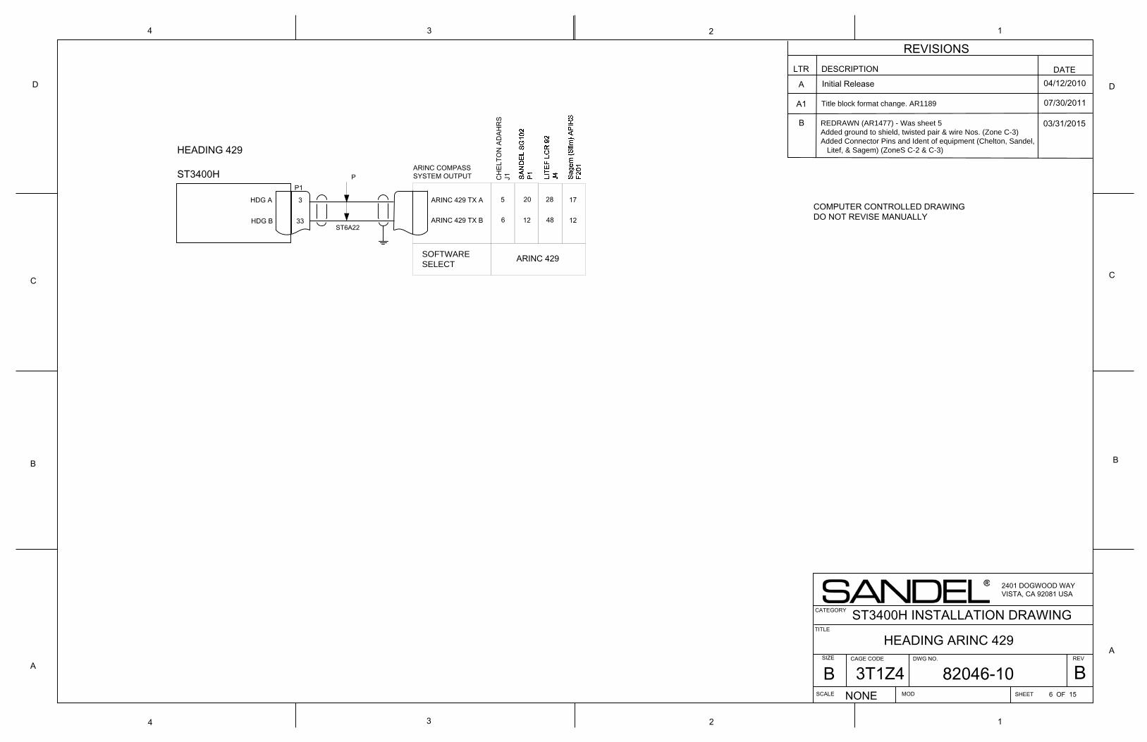
P1
HDG A
HDG B
3
33
ARINC COMPASS SYSTEM OUTPUT
HEADING 429
ST3400H
A
B
C
D
134
D
C
B
A
1
2
4 3 2
COMPUTER CONTROLLED DRAWINGDO NOT REVISE MANUALLY
P
TITLE
SIZE DWG NO.
SCALE SHEET
REV
NONE
2401 DOGWOOD WAYVISTA, CA 92081 USA
CAGE CODE
ST3400H INSTALLATION DRAWING
MOD 6 OF 15
CATEGORY
HEADING ARINC 429
LTR DESCRIPTION DATEA Initial Release 04/12/2010
A1 07/30/2011
03/31/2015
REVISIONS
Title block format change. AR1189
B
ARINC 429 TX A
ARINC 429 TX B
SOFTWARE SELECT
6
5
12
20
48
28
ARINC 429
CH
ELTO
N A
DAH
RS
J1
REDRAWN (AR1477) - Was sheet 5Added ground to shield, twisted pair & wire Nos. (Zone C-3)Added Connector Pins and Ident of equipment (Chelton, Sandel, Litef, & Sagem) (ZoneS C-2 & C-3)
12
17
ST6A22
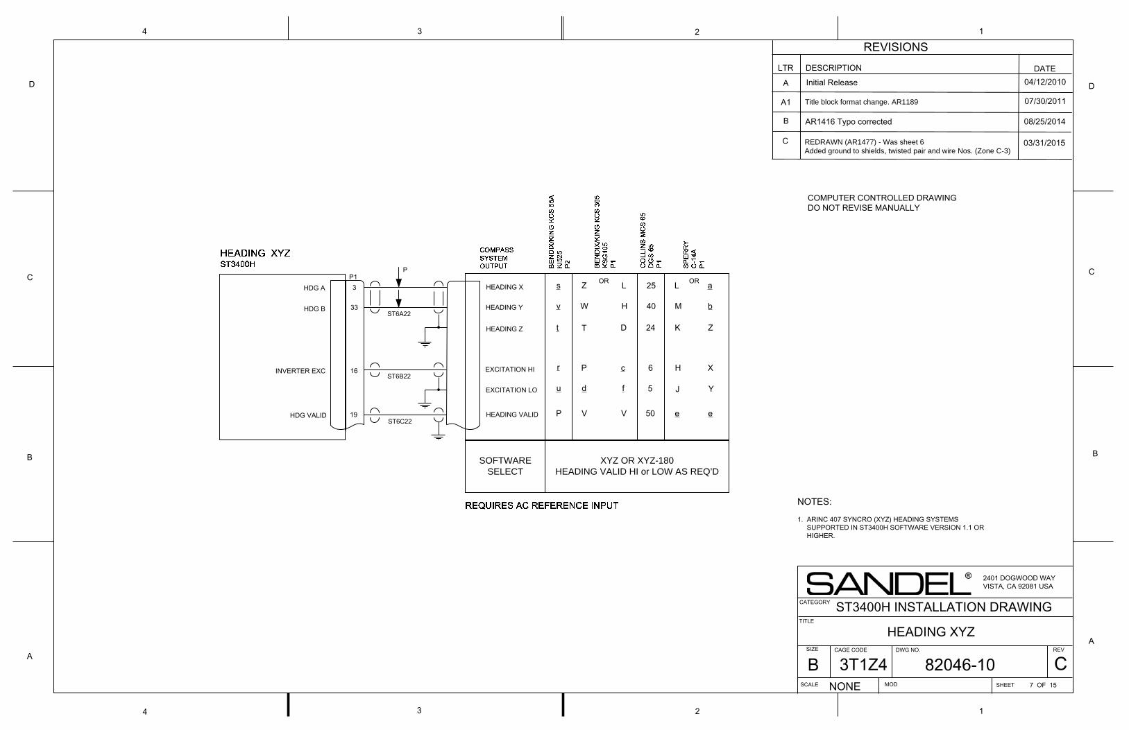
HEADING Y
HEADING XP1
HDG A
HEADING Z
HDG B
3
33
INVERTER EXC EXCITATION HI16
EXCITATION LO
HEADING VALID19HDG VALID
A
B
C
D
134
D
C
B
A
1
2
4 3 2
P
COMPUTER CONTROLLED DRAWINGDO NOT REVISE MANUALLY
LTR DESCRIPTION DATEA Initial Release 04/12/2010
A1 07/30/2011
08/25/2014
Title block format change. AR1189
B
REDRAWN (AR1477) - Was sheet 6Added ground to shields, twisted pair and wire Nos. (Zone C-3)
REVISIONS
TITLE
SIZE DWG NO.
SCALE SHEET
REV
NONE
2401 DOGWOOD WAYVISTA, CA 92081 USA
CAGE CODE
ST3400H INSTALLATION DRAWING
MOD 7 OF 15
CATEGORY
HEADING XYZ
s
v
r
P
u
t
Z
W
P
V
d
T
OR L
H
c
V
f
D
25
40
6
50
5
24
L
M
H
e
J
K
a
b
X
e
Y
Z
OR
SOFTWARESELECT
XYZ OR XYZ-180HEADING VALID HI or LOW AS REQ’D
NOTES:
1. ARINC 407 SYNCRO (XYZ) HEADING SYSTEMS SUPPORTED IN ST3400H SOFTWARE VERSION 1.1 OR HIGHER.
ST6A22
ST6B22
ST6C22
AR1416 Typo corrected
C 03/31/2015
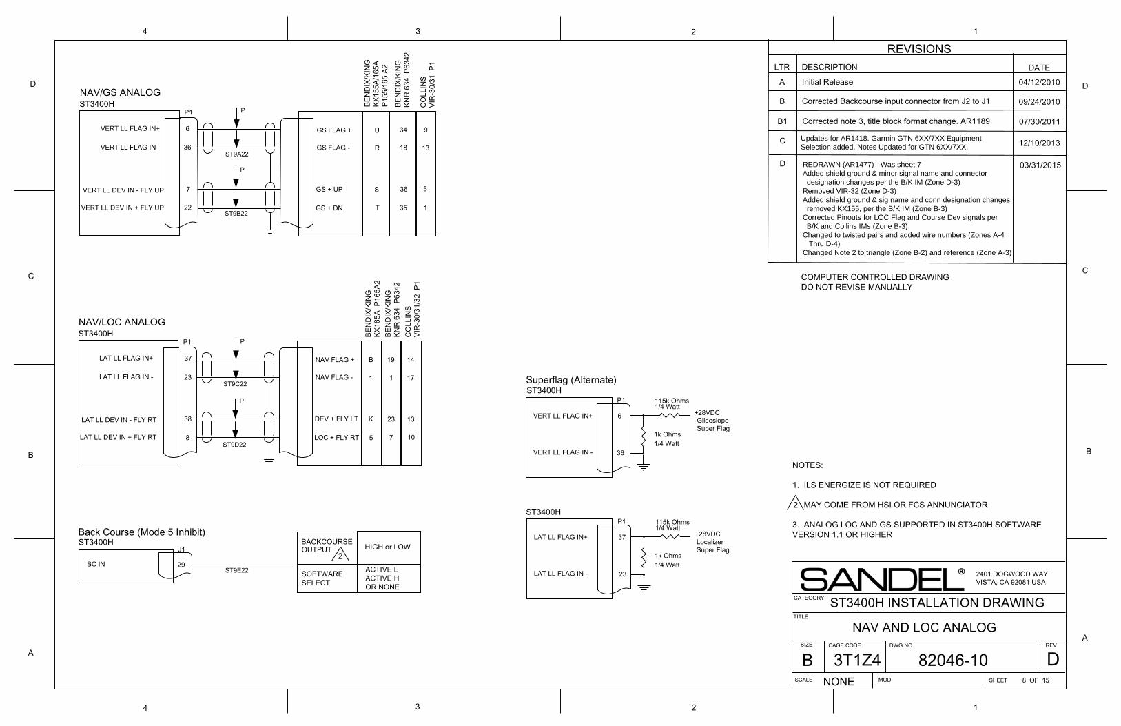
1k Ohms
115k Ohms
VERT LL FLAG IN -
ST3400HP1
VERT LL FLAG IN+ 6
36
VERT LL DEV IN - FLY UP
22
7
GS FLAG +
GS FLAG -
GS + DN
GS + UP
+28VDC
LocalizerSuper Flag
GlideslopeSuper Flag
P1ST3400H
6
361/4 Watt
1/4 Watt
J1
29BC IN
ST3400H BACKCOURSEOUTPUT HIGH or LOW
Back Course (Mode 5 Inhibit)
Superflag (Alternate)
NAV/GS ANALOG
VERT LL DEV IN + FLY UP
VERT LL FLAG IN+
VERT LL FLAG IN -
A
B
C
D
134
D
C
B
A
1
2
4 3 2
1k Ohms
115k Ohms
+28VDC
P1ST3400H
37
231/4 Watt
1/4 WattLAT LL FLAG IN+
LAT LL FLAG IN -
COMPUTER CONTROLLED DRAWINGDO NOT REVISE MANUALLY
REVISIONSLTR DESCRIPTION DATE
A Initial Release 04/12/2010
B 09/24/2010
B1 07/30/2011
Updates for AR1418. Garmin GTN 6XX/7XX Equipment Selection added. Notes Updated for GTN 6XX/7XX.
REDRAWN (AR1477) - Was sheet 7Added shield ground & minor signal name and connector designation changes per the B/K IM (Zone D-3)Removed VIR-32 (Zone D-3)Added shield ground & sig name and conn designation changes, removed KX155, per the B/K IM (Zone B-3)Corrected Pinouts for LOC Flag and Course Dev signals per B/K and Collins IMs (Zone B-3)Changed to twisted pairs and added wire numbers (Zones A-4 Thru D-4)Changed Note 2 to triangle (Zone B-2) and reference (Zone A-3)
12/10/2013
03/31/2015
TITLE
SIZE DWG NO.
SCALE SHEET
REV
NONE
2401 DOGWOOD WAYVISTA, CA 92081 USA
CAGE CODE
ST3400H INSTALLATION DRAWING
MOD 8 OF 15
CATEGORY
NAV AND LOC ANALOG
U
R
T
S
BEN
DIX
/KIN
G
KX15
5A/1
65A
P1
55/1
65 A
2
34
18
35
36
BEN
DIX
/KIN
G
KNR
634
P63
42
LAT LL FLAG IN -
ST3400HP1
LAT LL FLAG IN+ 37
23
LAT LL DEV IN - FLY RT
8
38
NAV FLAG +
NAV FLAG -
LOC + FLY RT
DEV + FLY LT
NAV/LOC ANALOG
LAT LL DEV IN + FLY RT
B
1
5
K
BEN
DIX
/KIN
G
KX16
5A P
165A
2
19
1
7
23
BEN
DIX
/KIN
G
KNR
634
P63
42
14
17
10
13C
OLL
INS
VIR
-30/
31/3
2 P
1
ACTIVE L ACTIVE H OR NONE
SOFTWARE SELECT
Corrected Backcourse input connector from J2 to J1
Corrected note 3, title block format change. AR1189
C
D
P
ST9A22
P
ST9B22
P
P
ST9C22
ST9D22
ST9E22
9
13
1
5
CO
LLIN
SVI
R-3
0/31
P1
2
NOTES:
1. ILS ENERGIZE IS NOT REQUIRED
MAY COME FROM HSI OR FCS ANNUNCIATOR
3. ANALOG LOC AND GS SUPPORTED IN ST3400H SOFTWARE VERSION 1.1 OR HIGHER
2
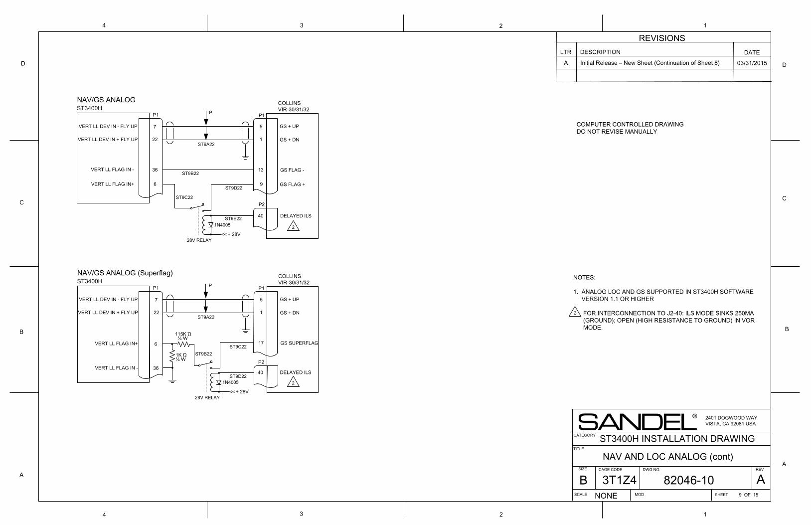
A
B
C
D
134
D
C
B
A
1
2
4 3 2
COMPUTER CONTROLLED DRAWINGDO NOT REVISE MANUALLY
REVISIONSLTR DESCRIPTION DATE
A Initial Release – New Sheet (Continuation of Sheet 8) 03/31/2015
TITLE
SIZE DWG NO.
SCALE SHEET
REV
NONE
2401 DOGWOOD WAYVISTA, CA 92081 USA
CAGE CODE
ST3400H INSTALLATION DRAWING
MOD 9 OF 15
CATEGORY
NAV AND LOC ANALOG (cont)
9
13
1
5
COLLINSVIR-30/31/32
VERT LL FLAG IN -
ST3400HP1
VERT LL FLAG IN+ 6
36
VERT LL DEV IN - FLY UP
22
7
GS FLAG +
GS FLAG -
GS + DN
GS + UP
NAV/GS ANALOG
VERT LL DEV IN + FLY UP
P
ST9A22
ST9B22
P1
1N4005
DELAYED ILS
<< + 28V28V RELAY
ST9C22
ST9D22
ST9E22
17
1
5
COLLINSVIR-30/31/32
VERT LL FLAG IN -
ST3400HP1
VERT LL FLAG IN+ 6
36
VERT LL DEV IN - FLY UP
22
7
GS SUPERFLAG
GS + DN
GS + UP
NAV/GS ANALOG (Superflag)
VERT LL DEV IN + FLY UP
P
ST9A22
ST9B22
P1
1N4005
P2
<< + 28V28V RELAY
ST9C22
ST9D22
115K Ώ ¼ W
1K Ώ¼ W
P2
40
DELAYED ILS40
2
2
NOTES:
1. ANALOG LOC AND GS SUPPORTED IN ST3400H SOFTWARE VERSION 1.1 OR HIGHER
FOR INTERCONNECTION TO J2-40: ILS MODE SINKS 250MA (GROUND); OPEN (HIGH RESISTANCE TO GROUND) IN VOR MODE.
2
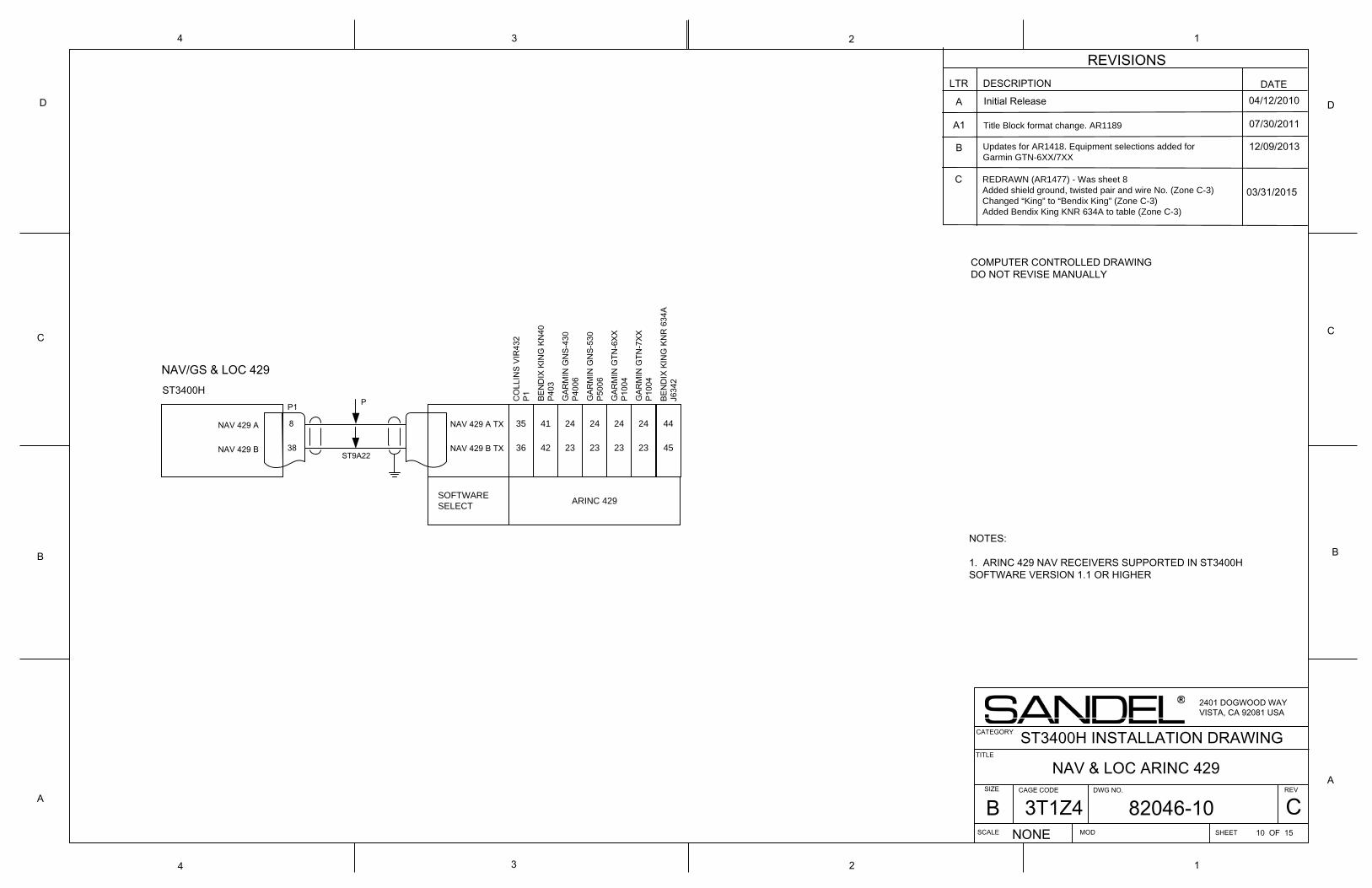
NAV 429 A TX
38
ST3400H
NAV 429 B TX
8
NAV 429 B
NAV 429 A
P1
NAV/GS & LOC 429
A
B
C
D
134
D
C
B
A
1
2
4 3 2
COMPUTER CONTROLLED DRAWINGDO NOT REVISE MANUALLY
LTR DESCRIPTION DATEA Initial Release 04/12/2010
A1 07/30/2011
B 12/09/2013
REDRAWN (AR1477) - Was sheet 8Added shield ground, twisted pair and wire No. (Zone C-3)Changed “King” to “Bendix King” (Zone C-3)Added Bendix King KNR 634A to table (Zone C-3)
REVISIONS
Updates for AR1418. Equipment selections added for Garmin GTN-6XX/7XX
C
TITLE
SIZE DWG NO.
SCALE SHEET
REV
NONE
2401 DOGWOOD WAYVISTA, CA 92081 USA
CAGE CODE
ST3400H INSTALLATION DRAWING
MOD 10 OF 15
CATEGORY
NAV & LOC ARINC 429
Title Block format change. AR1189
SOFTWARE SELECT
35
36
CO
LLIN
S VI
R43
2P1
41
42
BEN
DIX
KIN
G K
N40
P403
24
23
GAR
MIN
GN
S-43
0P4
006
24
23
GAR
MIN
GN
S-53
0P5
006
24
23
GAR
MIN
GTN
-6XX
P100
4
24
23
GAR
MIN
GTN
-7XX
P100
4
44
45
BEN
DIX
KIN
G K
NR
634
AJ6
342
ARINC 429
NOTES:
1. ARINC 429 NAV RECEIVERS SUPPORTED IN ST3400H SOFTWARE VERSION 1.1 OR HIGHER
P
ST9A22
03/31/2015
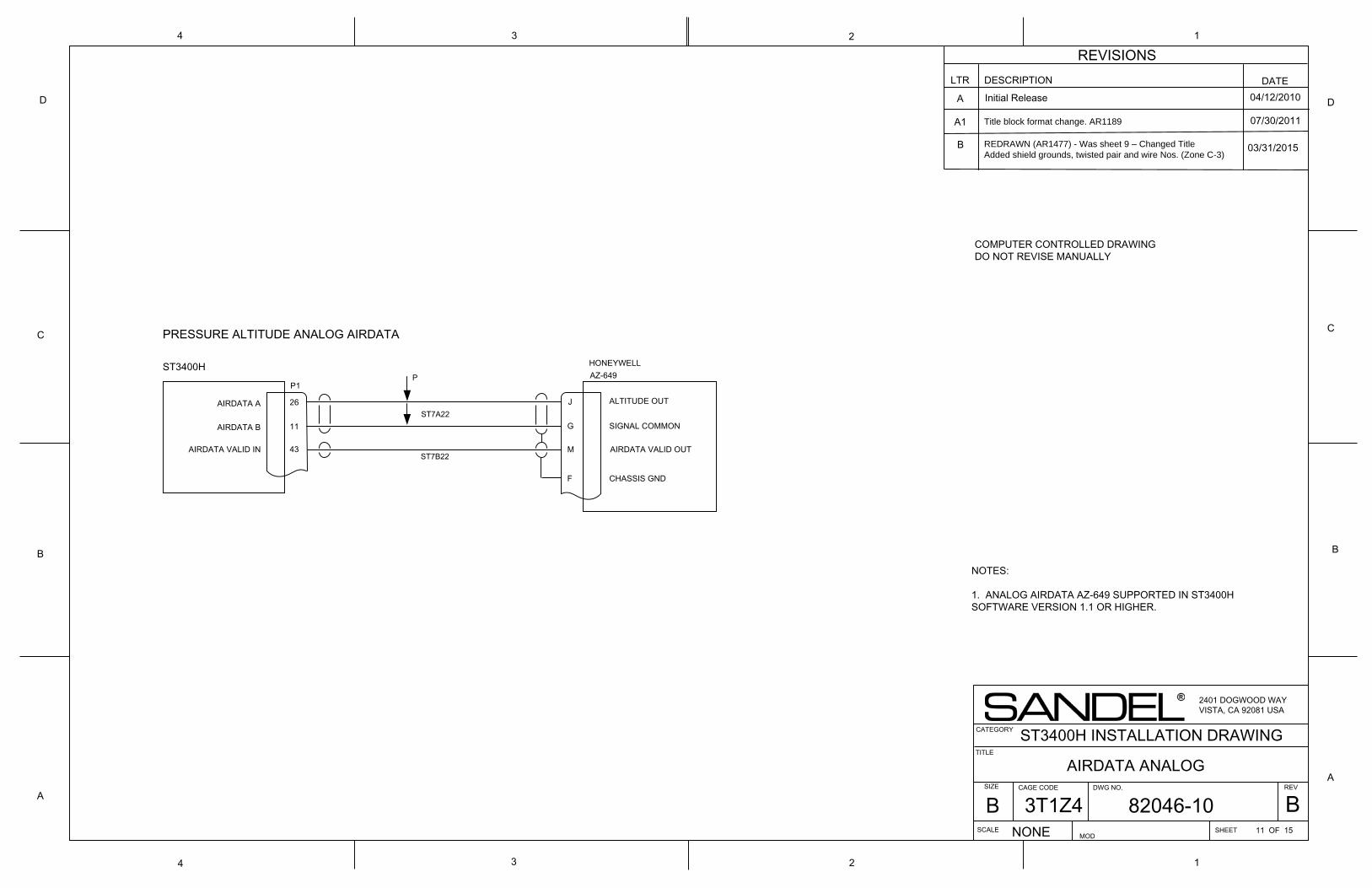
PRESSURE ALTITUDE ANALOG AIRDATA
SIGNAL COMMON
43 M
ST3400H
ALTITUDE OUT
P1
AIRDATA VALID IN
J
AIRDATA VALID OUT
G11
26
HONEYWELL AZ-649
AIRDATA A
AIRDATA B
CHASSIS GNDF
A
B
C
D
134
D
C
B
A
1
2
4 3 2
COMPUTER CONTROLLED DRAWINGDO NOT REVISE MANUALLY
P
LTR DESCRIPTION DATEA Initial Release 04/12/2010
A1 07/30/2011
REVISIONS
Title block format change. AR1189
B
TITLE
SIZE DWG NO.
SCALE SHEET
REV
NONE
2401 DOGWOOD WAYVISTA, CA 92081 USA
CAGE CODE
ST3400H INSTALLATION DRAWING
MOD11 OF 15
CATEGORY
AIRDATA ANALOG
REDRAWN (AR1477) - Was sheet 9 – Changed TitleAdded shield grounds, twisted pair and wire Nos. (Zone C-3)
NOTES:
1. ANALOG AIRDATA AZ-649 SUPPORTED IN ST3400H SOFTWARE VERSION 1.1 OR HIGHER.
ST7A22
ST7B22
03/31/2015
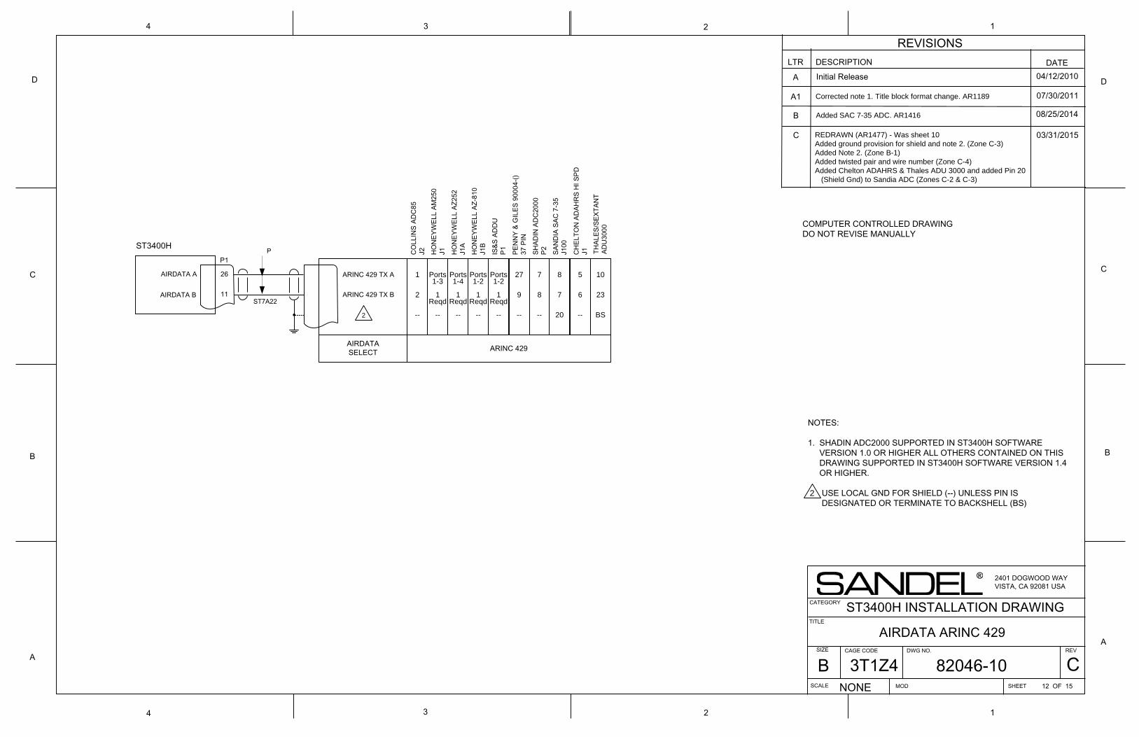
ST3400HP1
11
AIRDATA A
AIRDATA B
26
ARINC 429 TX B
ARINC 429 TX A
A
B
C
D
134
D
C
B
A
1
2
4 3 2
COMPUTER CONTROLLED DRAWINGDO NOT REVISE MANUALLY
P
LTR DESCRIPTION DATEA Initial Release 04/12/2010
A1 07/30/2011
08/25/2014
REVISIONS
Corrected note 1. Title block format change. AR1189
B
REDRAWN (AR1477) - Was sheet 10Added ground provision for shield and note 2. (Zone C-3)Added Note 2. (Zone B-1)Added twisted pair and wire number (Zone C-4)Added Chelton ADAHRS & Thales ADU 3000 and added Pin 20 (Shield Gnd) to Sandia ADC (Zones C-2 & C-3)
TITLE
SIZE DWG NO.
SCALE SHEET
REV
NONE
2401 DOGWOOD WAYVISTA, CA 92081 USA
CAGE CODE
ST3400H INSTALLATION DRAWING
MOD 12 OF 15
CATEGORY
AIRDATA ARINC 429
1
2
--
CO
LLIN
S AD
C85
J2
Ports1-3
1 Reqd
--
HO
NEY
WEL
L AM
250
J1
Ports1-4
1Reqd
--
HO
NEY
WEL
L AZ
252
J1A
Ports1-2
1Reqd
--
HO
NEY
WEL
L AZ
-810
J1B
Ports1-2
1Reqd
--
IS&S
AD
DU
P1
27
9
--
PEN
NY
& G
ILES
900
04-()
37 P
IN
7
8
--
SHAD
IN A
DC
2000
P2
5
6
--
CH
ELTO
N A
DAH
RS
HI S
PDJ1
8
7
20
SAN
DIA
SAC
7-3
5J1
00
AIRDATASELECT ARINC 429
10
23
BS
THAL
ES/S
EXTA
NT
ADU
3000
2
ST7A22
C
Added SAC 7-35 ADC. AR1416
03/31/2015
NOTES:
1. SHADIN ADC2000 SUPPORTED IN ST3400H SOFTWARE VERSION 1.0 OR HIGHER ALL OTHERS CONTAINED ON THIS DRAWING SUPPORTED IN ST3400H SOFTWARE VERSION 1.4 OR HIGHER.
USE LOCAL GND FOR SHIELD (--) UNLESS PIN IS DESIGNATED OR TERMINATE TO BACKSHELL (BS) 2
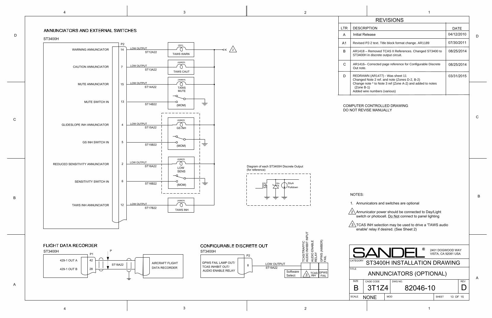
50v
WARNING ANNUNCIATOR
CAUTION ANNUNCIATOR
14
7
TAWS WARN
(RED)
ST3400H
ST3400HP2
MUTE ANNUNCIATOR 15
LOW OUTPUT
(AMBER)
TAWS INH ANNUNCIATOR
GLIDESLOPE INH ANNUNCIATOR 4
REDUCED SENSITIVITY ANNUNCIATOR
GS INH SWITCH IN
SENSITIVITY SWITCH IN
MUTE SWITCH IN
P1
42
28
429-1 OUT AAIRCRAFT FLIGHTDATA RECORDER
GPWS FAIL LAMP OUT/8 LOW OUTPUT
P2ST3400H
GPW
S (A
MBE
R)
FAIL
TCAS INHIBIT OUT/ Software Select
12
5
2
6
LOWSENS
(MOM)
(AMBER)
GS INH
(AMBER)
(MOM)
(AMBER)
(MOM)
TAWSMUTE
13
TAWS CAUT
LOW OUTPUT
LOW OUTPUT
LOW OUTPUT
LOW OUTPUT
GPWS FAIL
AUDIO ENABLE RELAY TCASINH
TCAS
/TR
AFFI
CAU
DIO
INH
IBIT
INPU
T
AUD
IO E
NAB
LER
ELAY
50uAPulldown
Diagram of each ST3400H Discrete Output(for reference)
TAWS INH
(AMBER)
LOW OUTPUT
429-1 OUT B
A
B
C
D
134
D
C
B
A
1
2
4 3 2
COMPUTER CONTROLLED DRAWINGDO NOT REVISE MANUALLY
LTR DESCRIPTION DATEA Initial Release 04/12/2010
A1 07/30/2011
08/25/2014
REVISIONS
Revised P2-2 text. Title block format change. AR1189
B
REDRAWN (AR1477) - Was sheet 11Changed Note 2 ref. and note (Zones D-2, B-2)Change note * to Note 3 ref (Zone A-2) and added to notes (Zone B-1)Added wire numbers (various)
TITLE
SIZE DWG NO.
SCALE SHEET
REV
NONE
2401 DOGWOOD WAYVISTA, CA 92081 USA
CAGE CODE
ST3400H INSTALLATION DRAWING
MOD 13 OF 15
CATEGORY
ANNUNCIATORS (OPTIONAL)
2
3
ST12A22
ST13A22
ST14A22
ST14B22
ST15A22
ST15B22
ST16A22
ST16B22
ST18A22
ST17B22
<< AR1418 – Removed TCAS II References. Changed ST3400 to ST3400H in discrete output circuit.
08/25/2014C AR1416– Corrected page reference for Configurable DiscreteOut note.
D 03/31/2015
P
ST19A22
NOTES:
1. Annunicators and switches are optional
Annunicator power should be connected to Day/Light switch or photocell. Do Not connect to panel lighting
TCAS INH selection may be used to drive a 'TAWS audio enable' relay if desired. (See Sheet 2)
2
3
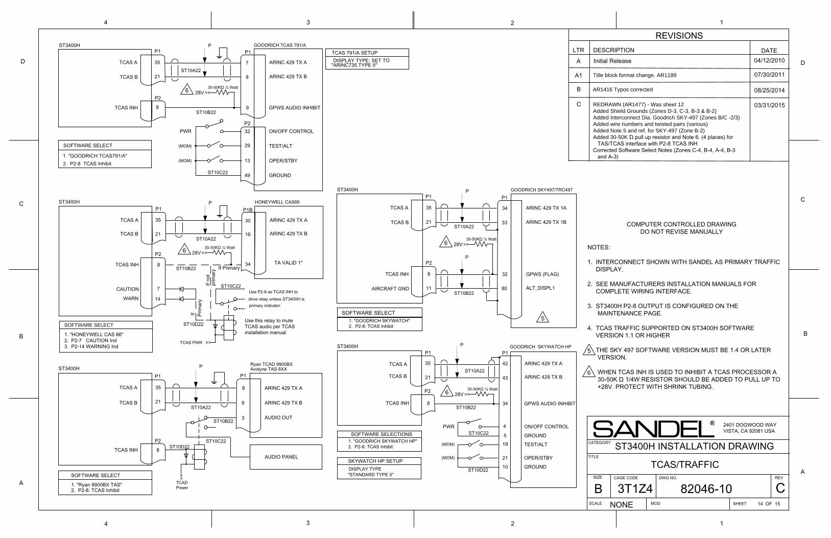
TCAS A
8
7
GOODRICH TCAS 791/AP1
21
35 ARINC 429 TX A
ARINC 429 TX BTCAS B
13
TEST/ALT
OPER/STBY
SOFTWARE SELECT
1. "GOODRICH TCAS791/A"
29
49 GROUND
ON/OFF CONTROL32
TCAS 791/A SETUPDISPLAY TYPE: SET TO
"ARINC735 TYPE II"
P1
8TCAS INH 9 GPWS AUDIO INHIBIT
P2
2. P2-8 TCAS Inhibit
16
30
HONEYWELL CAS66P1
ARINC 429 TX A
ARINC 429 TX B
SOFTWARE SELECT
P1B
8TCAS INH 34 TA VALID 1*
1. "HONEYWELL CAS 66"2. P2-7 CAUTION Ind3. P2-14 WARNING Ind
Use P2-8 as TCAS INH todrive relay unless ST3400H isprimary indicator.
7CAUTION
WARN 14
TCAS PWR
Use this relay to mute TCAS audio per TCAS installation manual
ST3400H
ST3400H
PWR
(MOM)
(MOM)
If Primary
If Prim
ary
If no
tpr
imar
y
4
TCAS INH19
ARINC 429 TX A
1. "Ryan 9900BX TAS"
ST3400HRyan TCAD 9900BXAvidyne TAS 6XX
TEST/ALT
ARINC 429 TX B
TCAD Power
9
AUDIO PANEL
2. P2-8: TCAS Inhibit
ARINC 429 TX A
P1
34
OPER/STBY
3
8
ON/OFF CONTROL
SOFTWARE SELECT
SOFTWARE SELECTIONS GROUND
43
TCAS INH
(MOM)
DISPLAY TYPE "STANDARD TYPE 5"
10
GOODRICH SKYWATCH HP
GROUND
(MOM)
1. "GOODRICH SKYWATCH HP"5
21
AUDIO OUT
PWR
ST3400H
GPWS AUDIO INHIBIT
P1
42
SKYWATCH HP SETUP
2. P2-8: TCAS Inhibit
ARINC 429 TX B
TCAS A
TCAS B
TCAS A
TCAS B
TCAS A
TCAS B
COMPUTER CONTROLLED DRAWINGDO NOT REVISE MANUALLY
P
P
P
P
P2
P2
21
35
P1
21
35
8
P2
P1
21
35
8
P2
A
B
C
D
134
D
C
B
A
1
2
4 3 2
LTR DESCRIPTION DATEA Initial Release 04/12/2010
A1 07/30/2011
08/25/2014
REVISIONS
Title block format change. AR1189
B
REDRAWN (AR1477) - Was sheet 12Added Shield Grounds (Zones D-3, C-3, B-3 & B-2)Added Interconnect Dia. Goodrich SKY-497 (Zones B/C -2/3)Added wire numbers and twisted pairs (various)Added Note 5 and ref. for SKY-497 (Zone B-2) Added 30-50K Ώ pull up resistor and Note 6. (4 places) for TAS/TCAS interface with P2-8 TCAS INHCorrected Software Select Notes (Zones C-4, B-4, A-4, B-3 and A-3)
TITLE
SIZE DWG NO.
SCALE SHEET
REV
NONE
2401 DOGWOOD WAYVISTA, CA 92081 USA
CAGE CODE
ST3400H INSTALLATION DRAWING
MOD 14 OF 15
CATEGORY
TCAS/TRAFFIC
TCAS A
33
34
GOODRICH SKY497/TRC497P1
21
35 ARINC 429 TX 1A
ARINC 429 TX 1BTCAS B
SOFTWARE SELECT
80
P1
TCAS INH
ST3400H P
P2
11
8 GPWS (FLAG)
ALT_DISPL1
32
P
AIRCRAFT GND
5
ST10A22
ST10B22
ST10A22
ST10A22
ST10A22
ST10B22
ST10C22
ST10B22
ST10B22
ST10A22
ST10C22
ST10D22
ST10D22
ST10B22
ST10C22
ST10D22 2. P2-8: TCAS Inhibit1. "GOODRICH SKYWATCH"
>>30-50KΏ ¼ Watt
28V
>>30-50KΏ ¼ Watt
28V6
6
>>30-50KΏ ¼ Watt
28V
6
6
>>30-50KΏ ¼ Watt
28V
>>
>>
ST10C22
AR1416 Typos corrected
03/31/2015C
NOTES:
1. INTERCONNECT SHOWN WITH SANDEL AS PRIMARY TRAFFIC DISPLAY.
2. SEE MANUFACTURERS INSTALLATION MANUALS FOR COMPLETE WIRING INTERFACE.
3. ST3400H P2-8 OUTPUT IS CONFIGURED ON THE MAINTENANCE PAGE.
4. TCAS TRAFFIC SUPPORTED ON ST3400H SOFTWARE VERSION 1.1 OR HIGHER
THE SKY 497 SOFTWARE VERSION MUST BE 1.4 OR LATER VERSION.
WHEN TCAS INH IS USED TO INHIBIT A TCAS PROCESSOR A 30-50K Ώ 1/4W RESISTOR SHOULD BE ADDED TO PULL UP TO +28V. PROTECT WITH SHRINK TUBING.
5
6
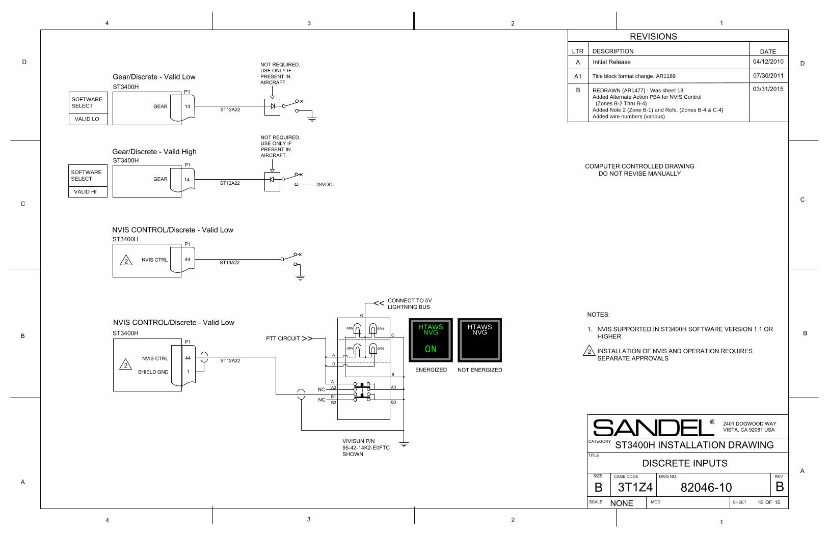
ST3400H
14GEAR
ST3400H
14GEAR28VDC
P1
P1
Gear/Discrete - Valid Low
Gear/Discrete - Valid High
P1ST3400H
44NVIS CTRL
NVIS CONTROL/Discrete - Valid Low
A
B
C
D
134
D
C
B
A
1
2
4 3 2
COMPUTER CONTROLLED DRAWINGDO NOT REVISE MANUALLY
LTR DESCRIPTION DATEA Initial Release 04/12/2010
A1 07/30/2011
03/31/2015
REVISIONS
Title block format change. AR1189
B REDRAWN (AR1477) - Was sheet 13Added Alternate Action PBA for NVIS Control (Zones B-2 Thru B-4)Added Note 2 (Zone B-1) and Refs. (Zones B-4 & C-4)Added wire numbers (various)
TITLE
SIZE DWG NO.
SCALE SHEET
REV
NONE
2401 DOGWOOD WAYVISTA, CA 92081 USA
CAGE CODE
ST3400H INSTALLATION DRAWING
MOD 15 OF 15
CATEGORY
DISCRETE INPUTS
NOT REQUIRED.USE ONLY IFPRESENT INAIRCRAFT.
NOT REQUIRED.USE ONLY IFPRESENT INAIRCRAFT.
P1ST3400H
44NVIS CTRL
GRN GRN
CONNECT TO 5V LIGHTNING BUS
GRN GRN
PTT CIRCUIT
1SHIELD GND
A
D
C
B
A1A2NC
NC B1B2 B3
A3
G
HTAWSNVG
ON
HTAWSNVG
ENERGIZED NOT ENERGIZED
VIVISUN P/N95-42-14K2-E0FTCSHOWN
NVIS CONTROL/Discrete - Valid Low
>>
>>
ST12A22
ST12A22
ST19A22
ST12A22
SOFTWARESELECT
VALID LO
SOFTWARESELECT
VALID HI
2
2
NOTES:
1. NVIS SUPPORTED IN ST3400H SOFTWARE VERSION 1.1 OR HIGHER
INSTALLATION OF NVIS AND OPERATION REQUIRES SEPARATE APPROVALS 2