Embed Size (px)
Citation preview
N87-11204
FLAME RADIATION
J. D. Wear
National Aeronautics and Space AdministrationLewis Research Center
INTRODUCTION
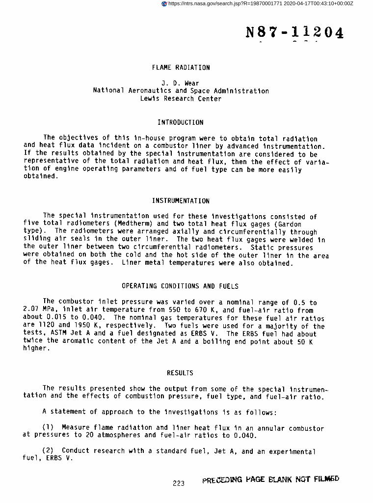
The objectives of this In-house program were to obtain total radiationand heat flux data incident on a combustor liner by advanced instrumentation.
If the results obtained by the special instrumentation are considered to be
representative of the total radiation and heat flux, then the effect of varia-
tion of engine operating parameters and of fuel type can be more easilyobtained.
INSTRUMENTATION
The special instrumentation used for these investigations consisted of
five total radiometers (Medtherm) and two total heat flux gages (Gardon
type). The radiometers were arranged axially and clrcumferentlally through
sliding air seals in the outer liner. The two heat flux gages were welded in
the outer liner between two circumferential radiometers. Static pressureswere obtained on both the cold and the hot side of the outer liner in the area
of the heat flux gages. Liner metal temperatures were also obtained.
OPERATING CONDITIONS AND FUELS
The combustor inlet pressure was varied over a nominal range of 0.5 to2.07 MPa, inlet air temperature from 550 to 670 K, and fuel-air ratio from
about O.Ol5 to 0.040. The nominal gas temperatures for these fuel air ratios
are ll20 and 1950 K, respectively. Two fuels were used for a majority of thetests, ASTM Jet A and a fuel designated as ERBS V. The ERBS fuel had about
twice the aromatic content of the Jet A and a boiling end point about 50 Khigher.
RESULTS
The results presented show the output from some of the special instrumen-tation and the effects of combustion pressure, fuel type, and fuel-alr ratio.
A statement of approach to the investigations is as follows:
(1) Measure flame radiation and liner heat flux in an annular combustorat pressures to 20 atmospheres and fuel-alr ratios to 0.040.
(2) Conduct research with a standard fuel, Jet A, and an experimentalfuel, ERBS V.
223 P-RE_iI_ I_AGE Eg,LANK NOT FII.III_D
https://ntrs.nasa.gov/search.jsp?R=19870001771 2020-04-17T00:43:10+00:00Z
(3) Evaluate the effects of pressure, fuel-alr ratio, and fuel type onradiation and liner heat flux.
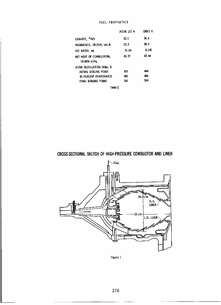
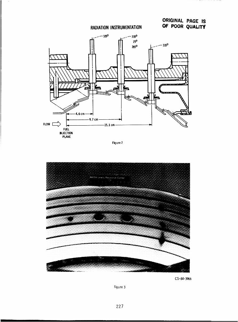
A cross-sectlonal sketch of the combustion system is shownin figure l.Fuel was injected by two rows of counterswirl Iow-Injectlon-pressure fuelmodules. Figure 2 shows the position of the radiometers. In figure 3 thepositions of four of the radiometers and the two heat flux gages are shownonthe hot gas side of the outer liner.
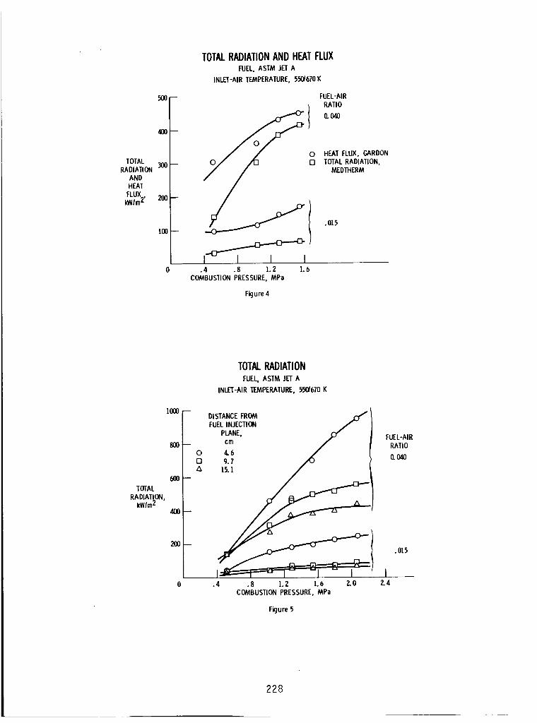
Comparisonof total radiation and total heat flux obtained at two fuel-air ratios and over a combustor pressure range is shownin figure 4 for Jet Afuel. At a fuel-alr ratio of 0.04 and a pressure of 0.5 MPa, total radiationwas about 46 percent of total heat flux. As the combustor pressure wasincreased to 1.6 MPa, total radiation increased to about 92 percent of totalheat flux.
The radiation values obtained from the three radiometers positionedaxially along the liner using Jet A are shownin figure 5. As the combustionpressure increased, the rate of radiation increase with pressure was greaterfor the radiometer closest to the fuel modules (4.6 cm from injection plane)than for the other two radiometers (9.7 and 15.1 cm from the injection plane).
A comparison of a few of the characteristics of the Jet A and ERBSVfuels used in the investigations (table I) indicates that the aromatic contentof the ERBSV is about twice that of the Jet A. Also the final boiling pointof the ERBSV is about 50 K greater than that of Jet A.
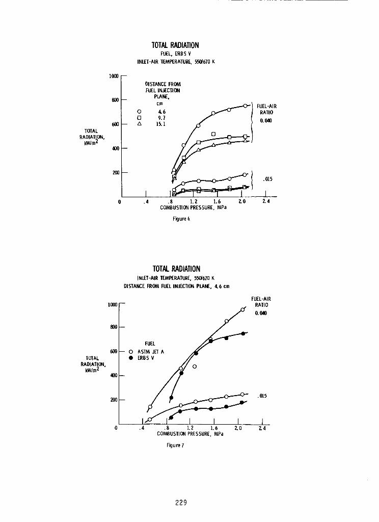
Figure 6 is a plot of total radiation data obtained from the threeIn-llne radiometers using ERBSV fuel. Again, the radiation obtained from theradiometer closest to the fuel modules was greater than that obtained from theother two radiometers.
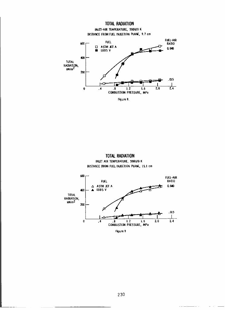
Comparisonof the radiation data obtained from the three In-llne radiome-ters for the two fuels is presented in figures 7 to 9. Figure 7 shows datafor the closest position, 4.6 cm from the fuel injection plane; figure 8, 9.7cm; and figure 9, 15.1 cm. As shown in figure 7, the radiation data obtainedwith Jet A are somewhatgreater than those obtained with ERBSV, at the twovalues of fuel-alr ratio. The difference is more pronounced at the higherpressure levels. At the 9.7- and 15.l-cm positions, the values obtained wlththe two fuels were similar, except at the low combustor pressure condition,where the Jet A fuel showedhigher radiation than with the ERBSV.
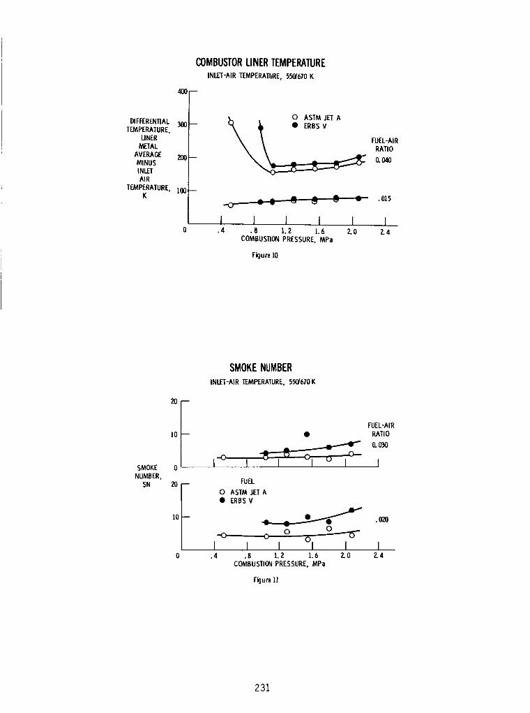
Liner differential temperatures (liner metal temperature minus inlet alrtemperature) as shownin figure lO are slightly higher with the ERBSV fuelthan with Jet A at the higher fuel-alr ratio of 0.04. Temperatures were simi-lar at a fuel-alr ratio of 0.015.
Figures II and 12 present smokenumber (SN) data for the two fuels atthree fuel-alr ratios of 0.02, 0.03, and 0.04 over the pressure range. Thesmokenumbersobtained with the ERBSV fuel were generally greater than thoseobtained with Jet A. The highest SN obtained was 25, wlth ERBSV fuel, 2.07MPapressure, and a fuel-alr ratio of 0.04.
224
SUMMARYOFRESULTS
l. At a fuel-alr ratio of 0.040, total radiation increased from about 46percent of total heat flux at a pressure of 0.5 MPato 92 percent of totalheat flux at 1.6 MPapressure.
2. The rate of total radiation increase with increase in pressure wasgreatest at the sample position closest to the fuel injection plane (4.6 cm).
3. Total radiation measuredat the 4.6 cm position was slightly greaterwlth Jet A than with ERBSV over the pressure range.
4. Smokenumbersobtained wlth ERBSV were somewhatgreater than thoseobtained with Jet A over the pressure range.
225
FUEL PROPERTIES
GRAVITY, °API
AROMATICS, (Dl319), vol.'_,
HIC RATIO, wL
NET HEAT Of COMBUSTION,
(D1405) kJIkg
ASTM DISTILLATION (D86), K
INITIAL BOIUNG POINT
50 PERCENT EVAPORATED
FINAL BOILING POINT
Table I
ASTM JET A ERBS V
43.1 36.6
15.5 30.2
0.161 0.147
43.27 42.44
433 444
483 486
547 594
CROSS-SECTIONALSKETCHOF HIGH-PRESSURECOMBUSTORAND LINER
_"_ FUEL
Figure ]
226
ORIGINAL PAGE 1s RADIATION INSTRUMENTATION OF: POOR QUALITY
FUEL INJECTION
PLANE
Figure 2
CS-84-3%6
Figure 3
227
TOTALRADIATION
ANDHEAT
FLUXkWlm2'
4_ --
300--
200--
100--
TOTALRADIATIONAND HEATFLUXFUEL,ASTM JETA
INLET'AIRTEMPERATURE,550/670K
017
I_1 ] I
FUEL-AIRRATIO
0. O40
HEATFLUX, GARDONTOTALRADIATION,
MEDTHERM
.4 .8 1.2 1.6COMBUSTIONPRESSURE, MPa
Figure4
TOTALRADIATIONFUEL,ASTM JETA
INLET-AIRTEMPERATURE,550/6/0 K
TOTALRADIATION,
kWIm2
1000--
800 --
600--
400--
200--
0[]L_
DISTANCEFROMFUELINJECTION
PLANE, jZ)f
cm /
¢69.7
15.1 '
AI
.4 .8 1.2 1.6 ZOCOMBUSTIONPRESSURE,MPa
Figure5
FUEL-AIRRATIO
(L040
,015
I2.4
228
TOTAL
RADIATkON,IdNIm_
I000--
800--
200--
TOTALRADIATIONFUEL,ERBSV
INLET-AIRTEMPERATURE,550/670K
DISTANCEFROMFUELINJECTION
PLANE,cm
O 4.60 9.7A B.I
O
, I I.4 .8 1.2 1.6 2.0
COMBUSTIONPRESSURE,MPa
Figure6,
FUEL-AIRRATIO
0.040
•015
I2.4
lOl_
6OOTOTAL
RADIATION,kWIm2
40O
2OO
TOTALRADIATION
INLET-AIRTEMPERATURE,550/670K
DISTANCEFROMFUELINJECTIONPLANE, 4.6 cm
FUEL-AIR-- RATIO
_ _ 0.040FUEL
ASTM JETA
_ .015
I I I I I.4 .8 1.Z 1.6 2.0 Z.4
COMBUSTIONPRESSURE,MPa
Figure1
229
TOTALRADIATION
INLET-AIR1EMPERATURE,55_b70 K
DISTANCEFROMFUELINJECTIONPLANE.9.7 ¢m
600 -- FUEL
400TOTAL
RADIATLON.kWIm':
2OO
FUEL-AIRRATIO
ASTM JETA
-/ " _ n _ .015I"_- Ir "r I" -I - I I
.4 .8 1.2 1.6 2.0 ?.4
COMBUSTIONPRESSURE,MPa
Figure8.
6OO
40O
TOTALRADIATION,
kWIm2 200
TOTALRADIATIONINLETAIR TEMPERATURE,55_670 K
DISTANCEFROM FUELINJECTIONPLANE,15.] cm
FUEL-AIRFUEL RATIO
ASTM JETA _ 0. 040
-- • ERB_
• __ .015
I-_-_-b_-" I-' _1 - I'-' 1.4 .8 1.2 1.6 Z.0 2.4
COMBUSTIONPRESSURE.MPa
Figure9
230
COMBUSTORLINERTEMPERATUREINLET-AIRTEMPERATURE,550/670K
400--
DIFFERENTIAL300TEMPERATURE,
UNERMETAL
AVERAGE 200MINUSiNLETAIR
TEMPERATURE,]00K
__ O ASTM JET A
• ERBS V
FUEL-AIRRATIO
0.040
- - C, _L .ms
I ] I I I ].4 .8 1.2 1.6 2.0 2.4
COMBUSTIONPRESSURE,MPa
Figure ]0.
20
]0
SMOKE 0NUMBER,
SN 20
10
SMOKENUMBER
INLET-AIRTEMPERATURE.550/670K
FUEL-AIR
• RATIO
I"° t J
a,l_,,
I.4
FUEL
0 ASTM JETA• ERBSV
7.020
O
o o °lI I I I.8 1.2 1.6 2.0 2.4
COMBUSTIONPRESSURE,MPa
Figure ]!
231
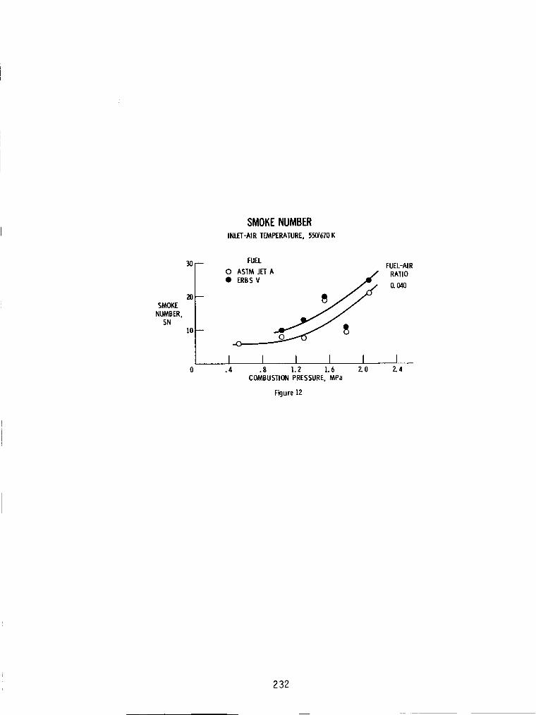
SMOKENUMBER
INLET-AIRTEMPERATURE,550/670K
SMOKENUMBER,
SN
FUEL FUEL-AIRO ASTM JETA RATIO
• _ERBS V 0.040
I I I I I ].4 .8 1.2 1.6 2.0 2.4
COMBUSTIONPRESSURE.MPa
Figure]2
232