Embed Size (px)
Citation preview
Sonex Aircraft, LLC
N604X
Pilot’s Operating Handbook
Revision 8Updated 08/19/2008
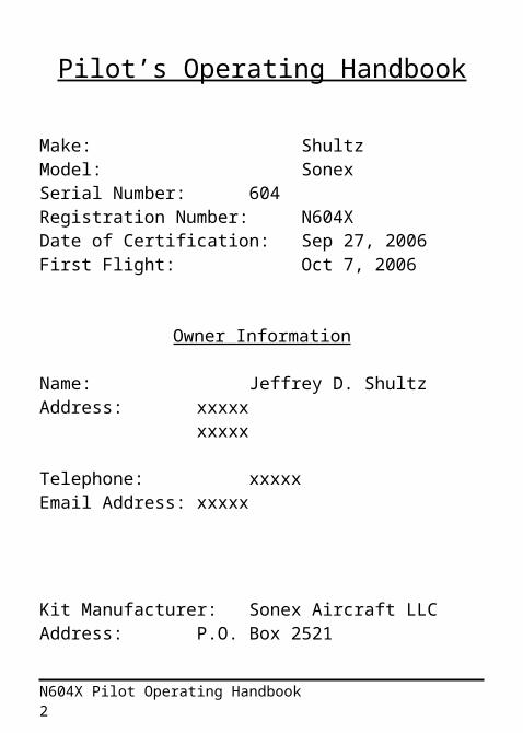
Pilot’s Operating Handbook
Make: ShultzModel: SonexSerial Number: 604Registration Number: N604XDate of Certification: Sep 27, 2006First Flight: Oct 7, 2006
Owner Information
Name: Jeffrey D. ShultzAddress: xxxxx
xxxxx
Telephone: xxxxxEmail Address: xxxxx
Kit Manufacturer: Sonex Aircraft LLCAddress: P.O. Box 2521
Oshkosh, WI 54903-2521
Telephone: 920-231-8297
N604X Pilot Operating Handbook 1
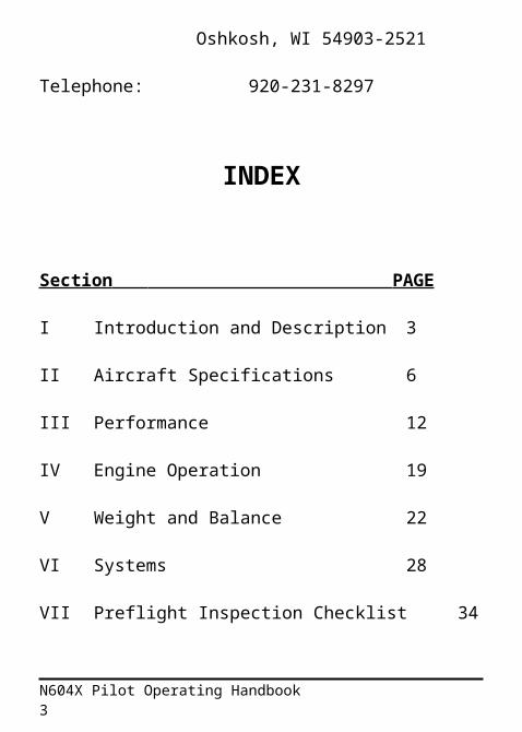
INDEX
Section PAGE
I Introduction and Description 3
II Aircraft Specifications 6
III Performance 12
IV Engine Operation 19
V Weight and Balance 22
VI Systems 28
VII Preflight Inspection Checklist 34
VIII Normal Procedures 37
IX Emergency Procedures 41
X Servicing Requirements 43
XI Equipment List 46
XII Passenger Disclaimer Form 48
XIII Revisions List 49
N604X Pilot Operating Handbook 2
I. Introduction and Description
The Sonex is a high-performance, homebuilt aircraft. Its compact external size and extremely efficient design results in superb performance and unequaled fuel economy using a relatively low horsepower engine. Even though the Sonex has relatively low horsepower, it can outperform many general aviation aircraft while retaining unequaled fuel economy. Typical cruise speed is 130 mph, burning under 4 gallons per hour, yielding fuel economy in excess of 30 miles per gallon.
The structure of the Sonex is almost entirely 6061T6 aluminum, yielding a design that is easy to construct, conventional to maintain, and resistant the effects of weather and corrosion.
The engine that powers the Sonex is an AeroVee 2180 aircraft engine, produced by AeroConversions, Inc. This engine features a forged steel crankshaft, dual spark plugs per cylinder, 4 independent ignition modules, adjustable mixture control, alternator, and electric starter. It is a lightweight, modern, reliable aircraft engine that is user-assembled and easily maintained. The AeroVee is fitted with an AeroCarb, offering superior operation, power, and efficiency in all modes of operation.
Flight Controls
Pitch and roll capability is accomplished by conventional dual control sticks located at each seat. Pitch control is provided by elevators mounted on the horizontal stabilizer. Roll control is accomplished by ailerons on the outboard portion of the main wing. Yaw control is provided by a rudder mounted on the vertical stabilizer, and is actuated by conventional rudder pedals. All flight controls including the flaps are pushrod actuated.
N604X Pilot Operating Handbook 3
An in-flight cockpit adjustable pitch trim system is provided. A lever mounted on the left cockpit sidewall adjusts a movable control tab mounted on the left elevator half. The trim system is completely independent of the normal pitch control system, thus providing back-up pitch control system in the event of a primary control problem. The primary pitch control system (i.e. the stick) can override any position of the trim system.
Engine Controls
The throttle, identified with a black handle, is located in the left of the instrument panel. It is a vernier style cable, which can be adjusted quickly by depressing the center button or set very precisely by rotating the handle. A vernier mixture control is located to the right of the throttle, and is identified by a red handle.
Landing Gear
The main landing gear legs are 1 1/8” titanium rod, mounted directly into the engine mount. Due to the mechanical properties of titanium, the Sonex gear is extremely robust, yet forgiving. The titanium gear legs will bend gently under landing loads, then rebound slowly without springing the aircraft back into the air. The tail wheel is mounted to a 5/8” titanium rod. Steering is accomplished through a direct linkage to the rudder, resulting in very accurate and positive directional control while taxiing, and during takeoff and landing.
Brakes
The braking system consists of mechanical drum brakes on each main tire, cable actuated by an aluminum lever in along the left hand cockpit sidewall. A catch bracket serves as a parking brake.
N604X Pilot Operating Handbook 4
Fuel System
The 17 gallon main fuel tank is located just aft of the firewall above the occupant’s legs. Unusable fuel quantity is less than ½ gallon. Fuel is delivered by gravity feed. A fuel shutoff valve is located inside the cockpit at the tank outlet, consisting of a ¼ turn ball valve. The fuel valve is closed by rotating the handle rearward so that it is perpendicular to the valve body. A capacitance fuel probe is installed to measure fuel quantity. Slight variations in fuel level readings are typical when comparing equal quantities of 100LL and auto fuel. However, the addition of alcohol and/or TCP fuel additive will introduce significant error into the fuel level displayed by the EIS until that fuel has been consumed. Fuel level should be checked while in level, balanced flight to avoid inaccurate fuel quantity measurements. The fuel filler cap is located on the upper forward fuselage, accessible from the outside of the aircraft through the fuel filler door in the cowling. Approved fuels include 92 octane automotive fuel and 100LL aviation fuel.
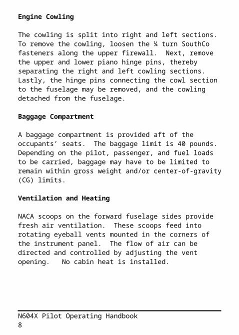
Engine Cowling
The cowling is split into right and left sections. To remove the cowling, loosen the ¼ turn SouthCo fasteners along the upper firewall. Next, remove the upper and lower piano hinge pins, thereby separating the right and left cowling sections. Lastly, the hinge pins connecting the cowl section to the fuselage may be removed, and the cowling detached from the fuselage.
Baggage Compartment
A baggage compartment is provided aft of the occupants’ seats. The baggage limit is 40 pounds. Depending on the pilot, passenger, and fuel loads to be carried, baggage may have to be limited to remain within gross weight and/or center-of-gravity (CG) limits.
N604X Pilot Operating Handbook 5
Ventilation and Heating
NACA scoops on the forward fuselage sides provide fresh air ventilation. These scoops feed into rotating eyeball vents mounted in the corners of the instrument panel. The flow of air can be directed and controlled by adjusting the vent opening. No cabin heat is installed.
N604X Pilot Operating Handbook 6
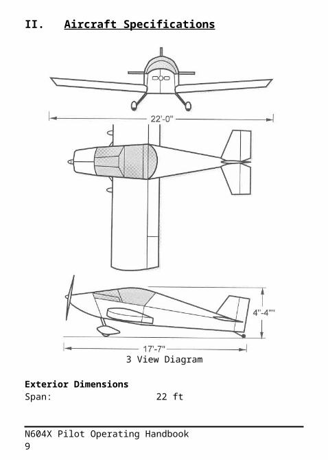
II. Aircraft Specifications
3 View Diagram
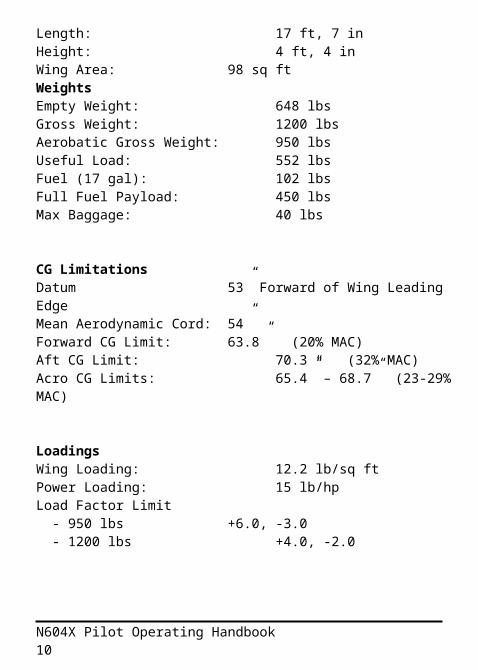
Exterior DimensionsSpan: 22 ftLength: 17 ft, 7 inHeight: 4 ft, 4 inWing Area: 98 sq ft
N604X Pilot Operating Handbook 7
WeightsEmpty Weight: 648 lbsGross Weight: 1200 lbsAerobatic Gross Weight: 950 lbsUseful Load: 552 lbsFuel (17 gal): 102 lbsFull Fuel Payload: 450 lbsMax Baggage: 40 lbs
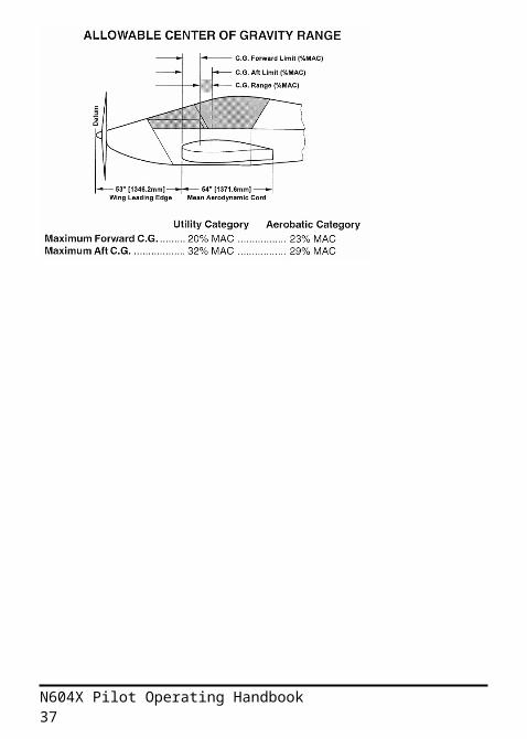
CG LimitationsDatum 53” Forward of Wing Leading EdgeMean Aerodynamic Cord: 54”Forward CG Limit: 63.8” (20% MAC)Aft CG Limit: 70.3 “ (32% MAC)Acro CG Limits: 65.4” – 68.7” (23-29% MAC)
LoadingsWing Loading: 12.2 lb/sq ftPower Loading: 15 lb/hpLoad Factor Limit - 950 lbs +6.0, -3.0 - 1200 lbs +4.0, -2.0
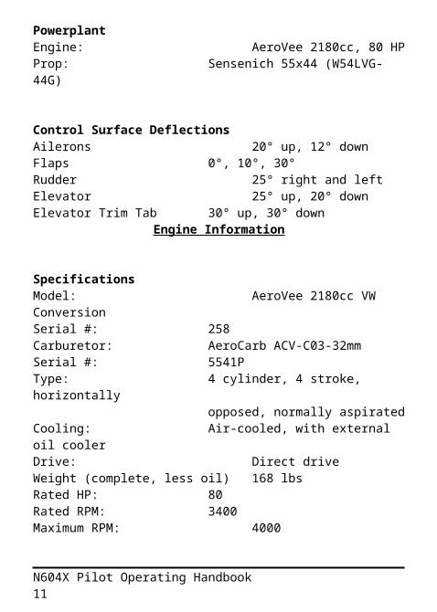
PowerplantEngine: AeroVee 2180cc, 80 HPProp: Sensenich 55x44 (W54LVG-44G)
Control Surface DeflectionsAilerons 20° up, 12° downFlaps 0°, 10°, 30°Rudder 25° right and left
N604X Pilot Operating Handbook 8
Elevator 25° up, 20° downElevator Trim Tab 30° up, 30° down
Engine Information
SpecificationsModel: AeroVee 2180cc VW ConversionSerial #: 258Carburetor: AeroCarb ACV-C03-32mmSerial #: 5541PType: 4 cylinder, 4 stroke, horizontally
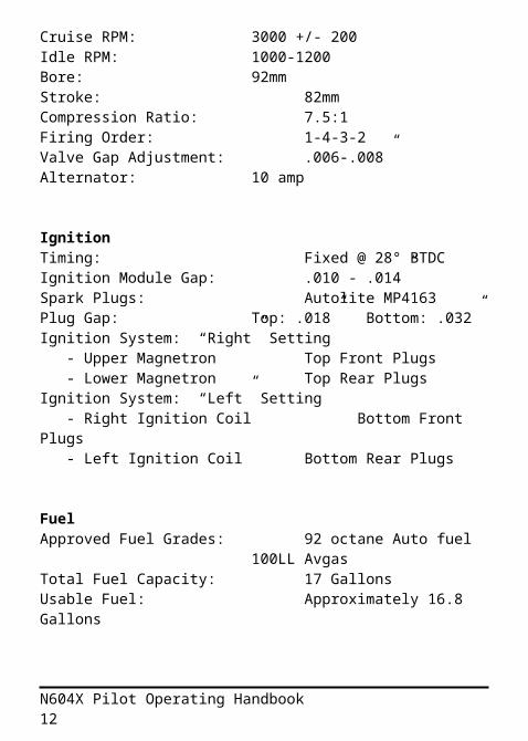
opposed, normally aspiratedCooling: Air-cooled, with external oil coolerDrive: Direct driveWeight (complete, less oil) 168 lbsRated HP: 80Rated RPM: 3400Maximum RPM: 4000Cruise RPM: 3000 +/- 200Idle RPM: 1000-1200Bore: 92mmStroke: 82mmCompression Ratio: 7.5:1Firing Order: 1-4-3-2Valve Gap Adjustment: .006-.008”Alternator: 10 amp
IgnitionTiming: Fixed @ 28° BTDCIgnition Module Gap: .010 - .014”Spark Plugs: Autolite MP4163Plug Gap: Top: .018” Bottom: .032”Ignition System: “Right” Setting - Upper Magnetron Top Front Plugs - Lower Magnetron Top Rear PlugsIgnition System: “Left” Setting
N604X Pilot Operating Handbook 9
- Right Ignition Coil Bottom Front Plugs - Left Ignition Coil Bottom Rear Plugs
FuelApproved Fuel Grades: 92 octane Auto fuel
100LL AvgasTotal Fuel Capacity: 17 GallonsUsable Fuel: Approximately 16.8 Gallons
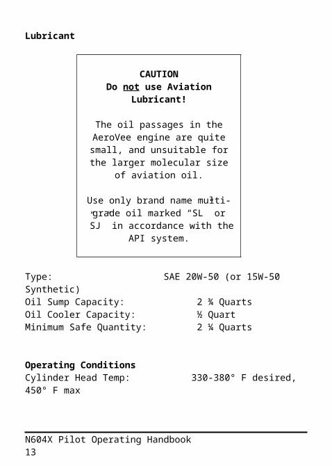
Lubricant
CAUTIONDo not use Aviation
Lubricant!
The oil passages in the AeroVee engine are quite small, and
unsuitable for the larger molecular size of aviation oil.
Use only brand name multi-grade oil marked “SL” or ”SJ” in accordance with the API system.
Type: SAE 20W-50 (or 15W-50 Synthetic)Oil Sump Capacity: 2 ¾ QuartsOil Cooler Capacity: ½ QuartMinimum Safe Quantity: 2 ¼ Quarts
Operating ConditionsCylinder Head Temp: 330-380° F desired, 450° F max
N604X Pilot Operating Handbook 10
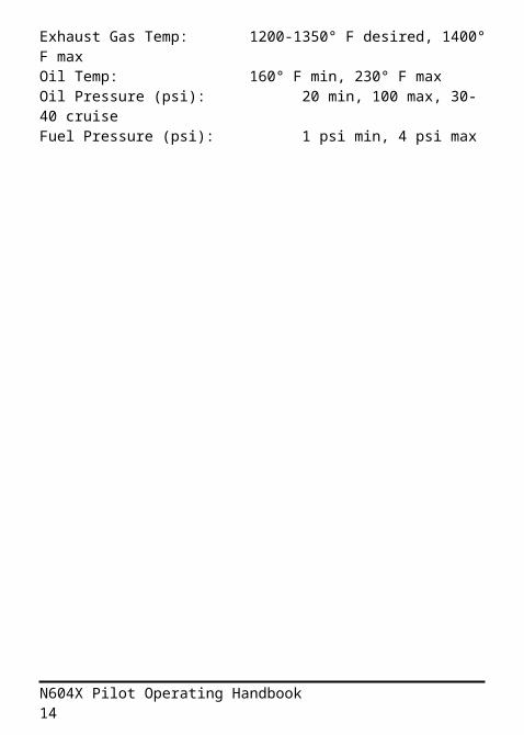
Exhaust Gas Temp: 1200-1350° F desired, 1400° F maxOil Temp: 160° F min, 230° F maxOil Pressure (psi): 20 min, 100 max, 30-40 cruiseFuel Pressure (psi): 1 psi min, 4 psi max
N604X Pilot Operating Handbook 11
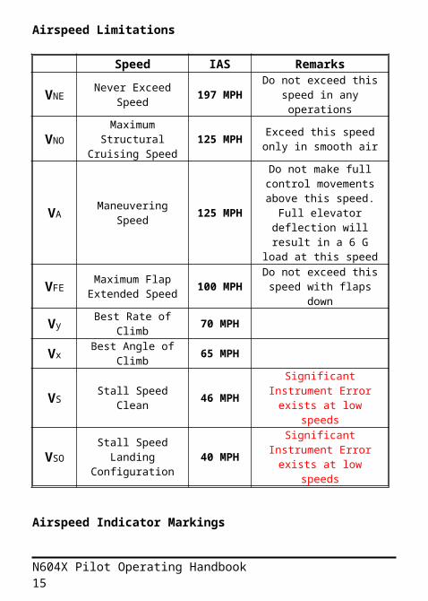
Airspeed Limitations
Speed IAS Remarks
VNE Never Exceed Speed
197 MPH
Do not exceed this speed in any operations
VNOMaximum Structural
Cruising Speed125 MPH
Exceed this speed only in smooth air
VA Maneuvering Speed
125 MPH
Do not make full control movements
above this speed. Full elevator deflection will result in a 6 G load at
this speedVFE Maximum Flap
Extended Speed100 MPH
Do not exceed this speed with flaps down
Vy Best Rate of Climb 70 MPH
Vx Best Angle of Climb 65 MPH
VS Stall Speed Clean 46 MPHSignificant Instrument
Error exists at low speeds
VSOStall Speed
Landing Configuration
40 MPHSignificant Instrument
Error exists at low speeds
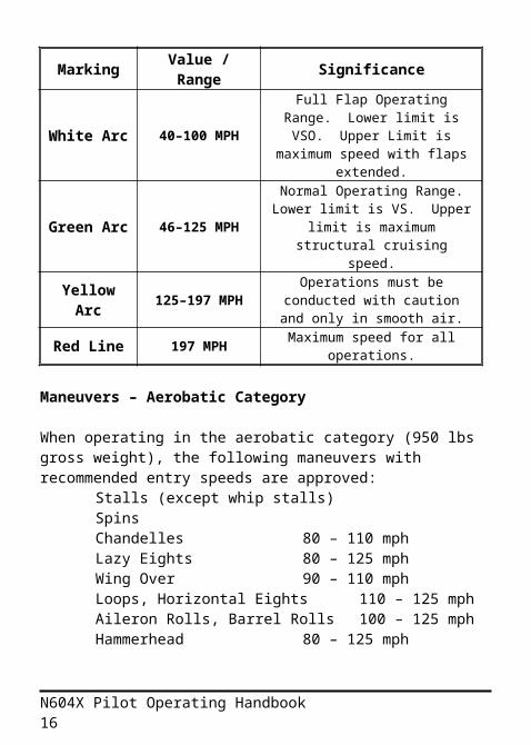
Airspeed Indicator Markings
Marking Value / Range Significance
White Arc 40–100 MPH
Full Flap Operating Range. Lower limit is VSO. Upper
Limit is maximum speed with flaps extended.
Green Arc 46–125 MPH
Normal Operating Range. Lower limit is VS. Upper limit
is maximum structural cruising speed.
N604X Pilot Operating Handbook 12
Yellow Arc 125–197 MPH
Operations must be conducted with caution and
only in smooth air.Red Line 197 MPH Maximum speed for all
operations.
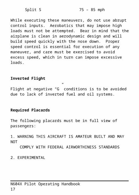
Maneuvers – Aerobatic Category
When operating in the aerobatic category (950 lbs gross weight), the following maneuvers with recommended entry speeds are approved:
Stalls (except whip stalls)Spins Chandelles 80 – 110 mphLazy Eights 80 – 125 mphWing Over 90 – 110 mphLoops, Horizontal Eights 110 – 125 mphAileron Rolls, Barrel Rolls 100 – 125 mphHammerhead 80 – 125 mphSplit S 75 – 85 mph
While executing these maneuvers, do not use abrupt control inputs. Aerobatics that may impose high loads must not be attempted. Bear in mind that the airplane is clean in aerodynamic design and will build speed quickly with the nose down. Proper speed control is essential for execution of any maneuver, and care must be exercised to avoid excess speed, which in turn can impose excessive loads.
Inverted Flight
Flight at negative “G” conditions is to be avoided due to lack of inverted fuel and oil systems.
Required Placards
The following placards must be in full view of passengers:
N604X Pilot Operating Handbook 13
1. WARNING THIS AIRCRAFT IS AMATEUR BUILT AND MAY NOT COMPLY WITH FEDERAL AIRWORTHINESS STANDARDS
2. EXPERIMENTAL
N604X Pilot Operating Handbook 14
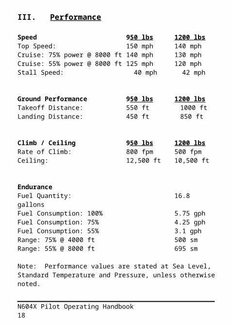
III. Performance
Speed 950 lbs 1200 lbsTop Speed: 150 mph 140 mphCruise: 75% power @ 8000 ft 140 mph 130 mphCruise: 55% power @ 8000 ft 125 mph 120 mphStall Speed: 40 mph 42 mph
Ground Performance 950 lbs 1200 lbsTakeoff Distance: 550 ft 1000 ftLanding Distance: 450 ft 850 ft
Climb / Ceiling 950 lbs 1200 lbsRate of Climb: 800 fpm 500 fpmCeiling: 12,500 ft 10,500 ft
EnduranceFuel Quantity: 16.8 gallonsFuel Consumption: 100% 5.75 gphFuel Consumption: 75% 4.25 gphFuel Consumption: 55% 3.1 gphRange: 75% @ 4000 ft 500 smRange: 55% @ 8000 ft 695 sm
Note: Performance values are stated at Sea Level, Standard Temperature and Pressure, unless otherwise noted.
N604X Pilot Operating Handbook 15
CRUISE PERFORMANCE (Full Fuel 17 Gal)
Altitude
(Feet)RPM %
BHPTAS
(MPH)
Fuel Flow (GPH)
Endurance
(Hours)Range (Miles)
S.L. 3300 100 130 5.7 2.8 3653200 87 125 5.0 3.2 4033100 77 120 4.4 3.6 4373000 70 115 4.0 4.0 4612900 60 110 3.4 4.7 5152800 55 105 3.1 5.1 536
4000 3300 87 140 5.0 3.2 4523200 76 135 4.3 3.7 5013100 67 130 3.8 4.2 5453000 61 124 3.5 4.6 5722900 52 119 3.0 5.4 6402800 48 113 2.7 5.9 663
8000 3300 77 151 4.4 3.6 5503200 67 145 3.8 4.2 6083100 59 139 3.4 4.7 6583000 54 133 3.1 5.2 6932900 46 128 2.6 6.1 7782800 42 122 2.4 6.6 809
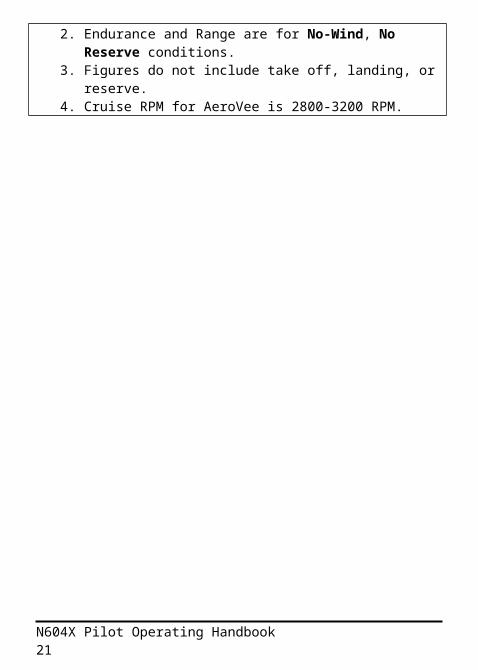
1. Maximum Cruise is normally limited to 75% power.2. Endurance and Range are for No-Wind, No
Reserve conditions.3. Figures do not include take off, landing, or reserve.4. Cruise RPM for AeroVee is 2800-3200 RPM.
N604X Pilot Operating Handbook 16
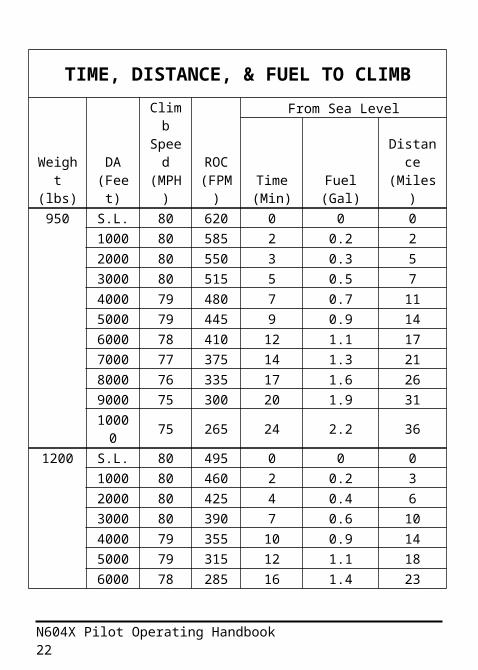
TIME, DISTANCE, & FUEL TO CLIMB
Weight (lbs)
DA (Feet
)
Climb
Speed
(MPH)
ROC (FPM
)
From Sea Level
Time (Min)
Fuel (Gal)
Distance
(Miles)950 S.L. 80 620 0 0 0
1000 80 585 2 0.2 22000 80 550 3 0.3 53000 80 515 5 0.5 74000 79 480 7 0.7 115000 79 445 9 0.9 146000 78 410 12 1.1 177000 77 375 14 1.3 218000 76 335 17 1.6 269000 75 300 20 1.9 311000
0 75 265 24 2.2 361200 S.L. 80 495 0 0 0
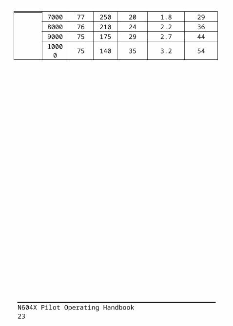
1000 80 460 2 0.2 32000 80 425 4 0.4 63000 80 390 7 0.6 104000 79 355 10 0.9 145000 79 315 12 1.1 186000 78 285 16 1.4 237000 77 250 20 1.8 298000 76 210 24 2.2 369000 75 175 29 2.7 44
N604X Pilot Operating Handbook 17
10000 75 140 35 3.2 54
N604X Pilot Operating Handbook 18
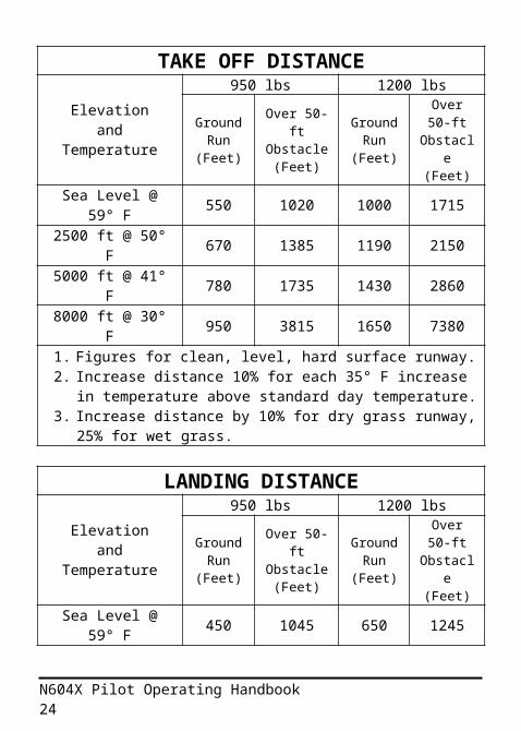
TAKE OFF DISTANCE
Elevation and Temperature
950 lbs 1200 lbsGround
Run (Feet)
Over 50-ft Obstacle
(Feet)
Ground Run
(Feet)
Over 50-ft
Obstacle (Feet)
Sea Level @ 59° F 550 1020 1000 1715
2500 ft @ 50° F 670 1385 1190 21505000 ft @ 41° F 780 1735 1430 28608000 ft @ 30° F 950 3815 1650 73801. Figures for clean, level, hard surface runway.2. Increase distance 10% for each 35° F increase in
temperature above standard day temperature.3. Increase distance by 10% for dry grass runway, 25%
for wet grass.
LANDING DISTANCE
Elevation and Temperature
950 lbs 1200 lbsGround
Run (Feet)
Over 50-ft Obstacle
(Feet)
Ground Run
(Feet)
Over 50-ft
Obstacle (Feet)
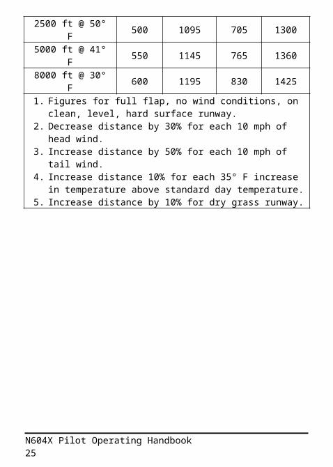
Sea Level @ 59° F 450 1045 650 1245
2500 ft @ 50° F 500 1095 705 13005000 ft @ 41° F 550 1145 765 13608000 ft @ 30° F 600 1195 830 14251. Figures for full flap, no wind conditions, on clean, level,
hard surface runway.2. Decrease distance by 30% for each 10 mph of head
wind.3. Increase distance by 50% for each 10 mph of tail wind.4. Increase distance 10% for each 35° F increase in
N604X Pilot Operating Handbook 19

temperature above standard day temperature.5. Increase distance by 10% for dry grass runway.
N604X Pilot Operating Handbook 20
N604X Pilot Operating Handbook 21
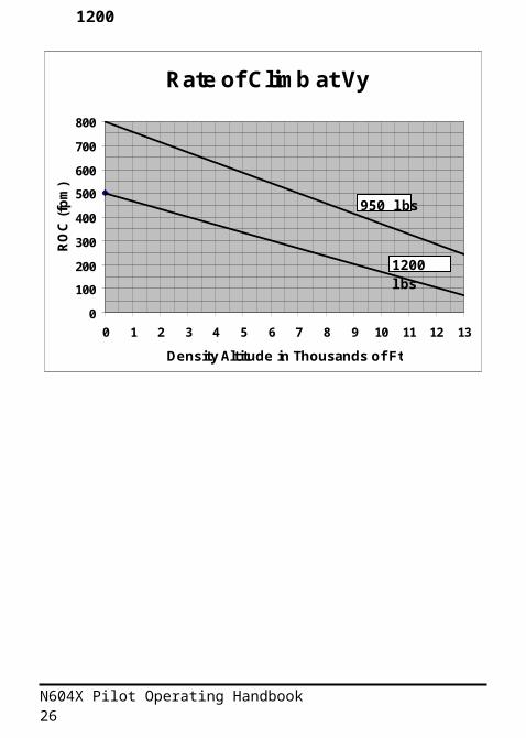
Rate of Climb at Vy
0
100
200
300
400
500
600
700
800
0 1 2 3 4 5 6 7 8 9 10 11 12 13
Density Altitude in Thousands of Ft
RO
C (f
pm)
1200 lbs
950 lbs
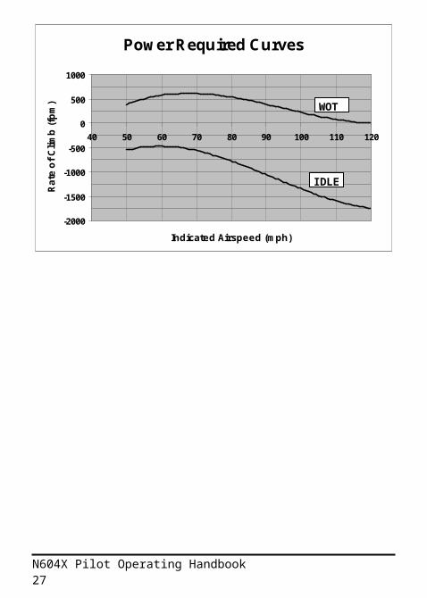
Power Required Curves
-2000
-1500
-1000
-500
0
500
1000
40 50 60 70 80 90 100 110 120
Indicated Airspeed (mph)
Rate
of C
limb
(fpm
) WOT
IDLE
1200 lbs
STATUTE MILES OR MPH
250225200175150125100755025
0 20 40 60 80 120100 140 160 200180 220 260240 280
0NAUTICAL MILES OR KNOTS
11090705030
TEMPERATURE C5040302010-30 -20 -10 0
120100 1109070 80605030 4020100-10-20TEMPERATURE F
DENS
ITY
ALTI
TUDE
(ft)
IND PRESSURE ALTITUDE @ 29.92 inHg10000 8000
6000
4000
2000
MSL
12010080604020
2000
6000
10000
12000
8000
4000
MSL
900011000 7000
5000
3000
1000
Estimating Density Altitude
N604X Pilot Operating Handbook 22
Pressure Altitude @ 29.92 in HgD
ensi
ty A
ltitu
de (
ft)
N604X Pilot Operating Handbook 23
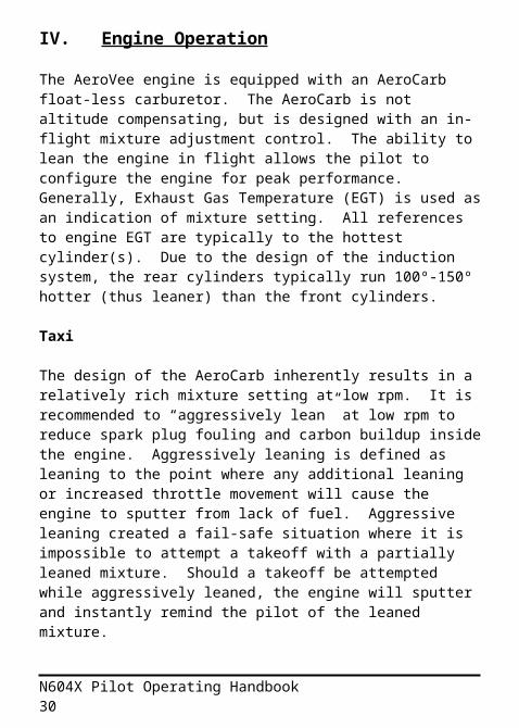
IV. Engine OperationThe AeroVee engine is equipped with an AeroCarb float-less carburetor. The AeroCarb is not altitude compensating, but is designed with an in-flight mixture adjustment control. The ability to lean the engine in flight allows the pilot to configure the engine for peak performance. Generally, Exhaust Gas Temperature (EGT) is used as an indication of mixture setting. All references to engine EGT are typically to the hottest cylinder(s). Due to the design of the induction system, the rear cylinders typically run 100º-150º hotter (thus leaner) than the front cylinders.
Taxi
The design of the AeroCarb inherently results in a relatively rich mixture setting at low rpm. It is recommended to “aggressively lean” at low rpm to reduce spark plug fouling and carbon buildup inside the engine. Aggressively leaning is defined as leaning to the point where any additional leaning or increased throttle movement will cause the engine to sputter from lack of fuel. Aggressive leaning created a fail-safe situation where it is impossible to attempt a takeoff with a partially leaned mixture. Should a takeoff be attempted while aggressively leaned, the engine will sputter and instantly remind the pilot of the leaned mixture.
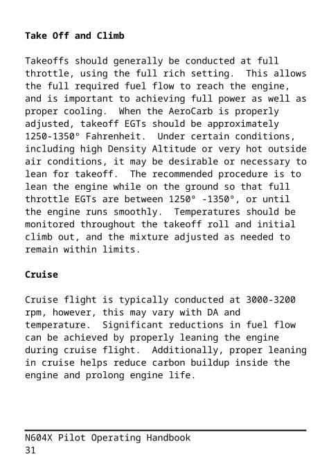
Take Off and Climb
Takeoffs should generally be conducted at full throttle, using the full rich setting. This allows the full required fuel flow to reach the engine, and is important to achieving full power as well as proper cooling. When the AeroCarb is properly adjusted, takeoff EGTs should be approximately 1250-1350º Fahrenheit. Under certain conditions, including high Density Altitude or very hot outside air conditions, it may be desirable or necessary to lean for takeoff. The recommended procedure is to lean the engine while on the
N604X Pilot Operating Handbook 24
ground so that full throttle EGTs are between 1250º -1350º, or until the engine runs smoothly. Temperatures should be monitored throughout the takeoff roll and initial climb out, and the mixture adjusted as needed to remain within limits.
Cruise
Cruise flight is typically conducted at 3000-3200 rpm, however, this may vary with DA and temperature. Significant reductions in fuel flow can be achieved by properly leaning the engine during cruise flight. Additionally, proper leaning in cruise helps reduce carbon buildup inside the engine and prolong engine life.
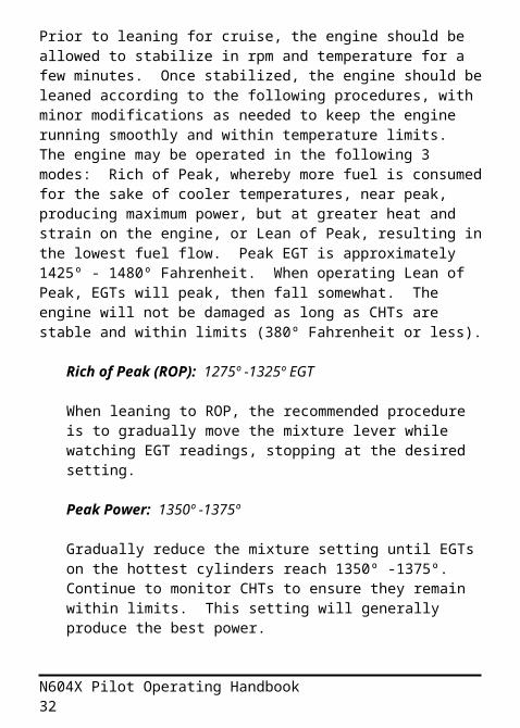
Prior to leaning for cruise, the engine should be allowed to stabilize in rpm and temperature for a few minutes. Once stabilized, the engine should be leaned according to the following procedures, with minor modifications as needed to keep the engine running smoothly and within temperature limits. The engine may be operated in the following 3 modes: Rich of Peak, whereby more fuel is consumed for the sake of cooler temperatures, near peak, producing maximum power, but at greater heat and strain on the engine, or Lean of Peak, resulting in the lowest fuel flow. Peak EGT is approximately 1425º - 1480º Fahrenheit. When operating Lean of Peak, EGTs will peak, then fall somewhat. The engine will not be damaged as long as CHTs are stable and within limits (380º Fahrenheit or less).
Rich of Peak (ROP): 1275º -1325º EGT
When leaning to ROP, the recommended procedure is to gradually move the mixture lever while watching EGT readings, stopping at the desired setting.
Peak Power: 1350º -1375º
N604X Pilot Operating Handbook 25
Gradually reduce the mixture setting until EGTs on the hottest cylinders reach 1350º -1375º. Continue to monitor CHTs to ensure they remain within limits. This setting will generally produce the best power.
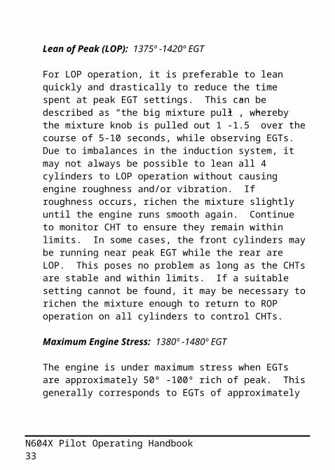
Lean of Peak (LOP): 1375º -1420º EGT
For LOP operation, it is preferable to lean quickly and drastically to reduce the time spent at peak EGT settings. This can be described as “the big mixture pull”, whereby the mixture knob is pulled out 1”-1.5” over the course of 5-10 seconds, while observing EGTs. Due to imbalances in the induction system, it may not always be possible to lean all 4 cylinders to LOP operation without causing engine roughness and/or vibration. If roughness occurs, richen the mixture slightly until the engine runs smooth again. Continue to monitor CHT to ensure they remain within limits. In some cases, the front cylinders may be running near peak EGT while the rear are LOP. This poses no problem as long as the CHTs are stable and within limits. If a suitable setting cannot be found, it may be necessary to richen the mixture enough to return to ROP operation on all cylinders to control CHTs.
Maximum Engine Stress: 1380º -1480º EGT
The engine is under maximum stress when EGTs are approximately 50º -100º rich of peak. This generally corresponds to EGTs of approximately 1380º -1480º. High power settings should be avoided in this mixture range.
Descent
Descent may be initiated by simply reducing the throttle to the desired rpm, while leaving the mixture setting leaned as
N604X Pilot Operating Handbook 26
in cruise. This will help prevent cooling the engine excessively during the descent and low power operation. Prior to resuming application of cruise power setting, as in entering the traffic pattern, the mixture should be adjusted or richened accordingly. In the event of a touch-and-go landing, or go-around, the mixture should be returned to the takeoff setting (full rich, or leaned as appropriate) before advancing the throttle to full.
N604X Pilot Operating Handbook 27

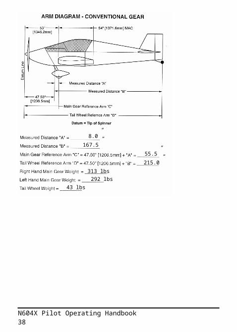
V. Weight and Balance
N604X Pilot Operating Handbook 28
N604X Pilot Operating Handbook 29
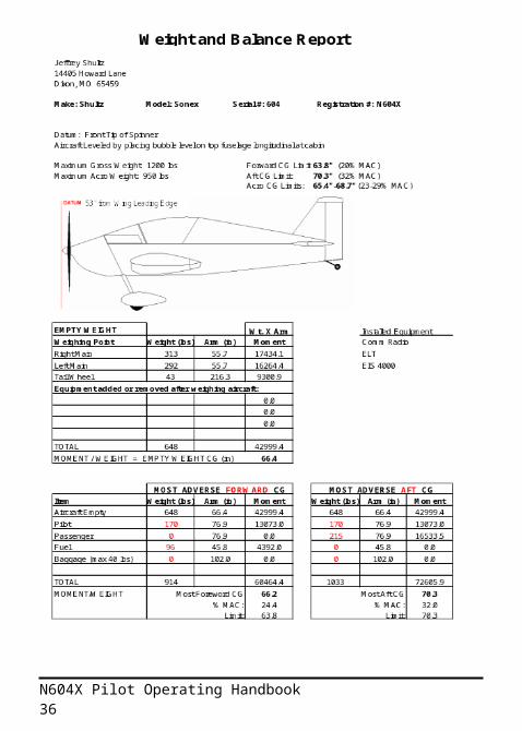
313 lbs 292 lbs
43 lbs
8.0”
167.5”
55.5”
215.0”
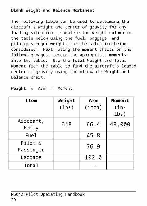
Blank Weight and Balance Worksheet
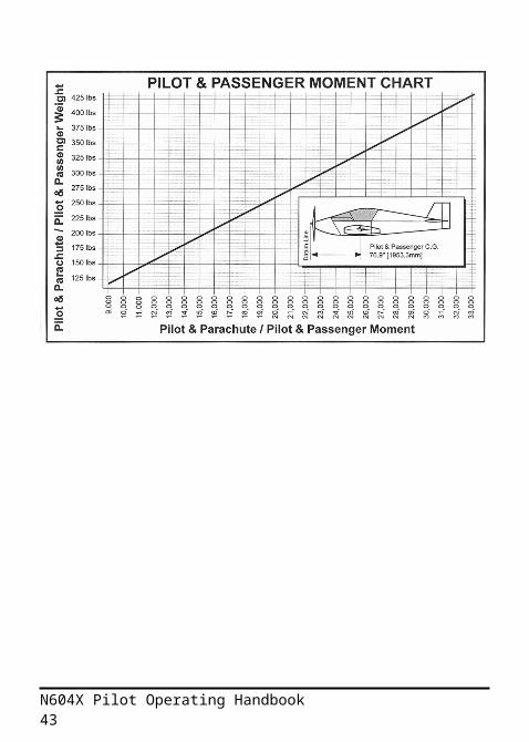
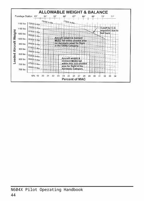
The following table can be used to determine the aircraft’s weight and center of gravity for any loading situation. Complete the weight column in the table below using the fuel, baggage, and pilot/passenger weights for the situation being considered. Next, using the moment charts on the following pages, record the appropriate moments into the table. Use the Total Weight and Total Moment from the table to find the aircraft’s loaded center of gravity using the Allowable Weight and Balance chart.
Weight x Arm = Moment
Item Weight(lbs)
Arm(inch)
Moment
(in-lbs)Aircraft, Empty 648 66.4 43,000
Fuel 45.8Pilot &
Passenger 76.9Baggage 102.0
Total ---
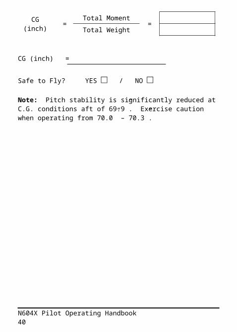
CG (inch) =Total Moment
=Total Weight
CG (inch) =
Safe to Fly? YES □ / NO □
N604X Pilot Operating Handbook 30
Note: Pitch stability is significantly reduced at C.G. conditions aft of 69.9”. Exercise caution when operating from 70.0” – 70.3”.
N604X Pilot Operating Handbook 31
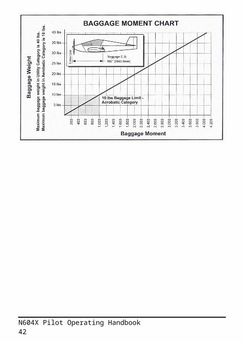
Moments
N604X Pilot Operating Handbook 32
Fuel = 6 lbs / gal
N604X Pilot Operating Handbook 33
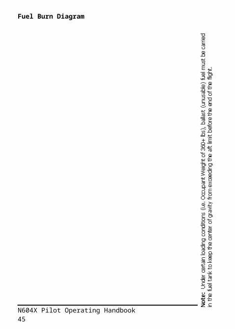
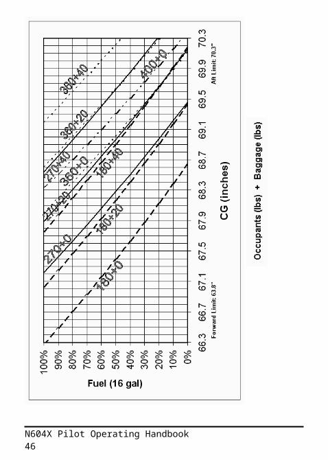
Fuel Burn Diagram
N604X Pilot Operating Handbook 34
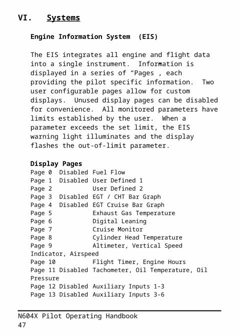
VI. SystemsEngine Information System (EIS)
The EIS integrates all engine and flight data into a single instrument. Information is displayed in a series of “Pages”, each providing the pilot specific information. Two user configurable pages allow for custom displays. Unused display pages can be disabled for convenience. All monitored parameters have limits established by the user. When a parameter exceeds the set limit, the EIS warning light illuminates and the display flashes the out-of-limit parameter.
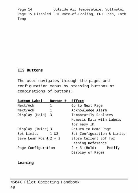
Display PagesPage 0 Disabled Fuel FlowPage 1 Disabled User Defined 1Page 2 User Defined 2Page 3 Disabled EGT / CHT Bar GraphPage 4 Disabled EGT Cruise Bar GraphPage 5 Exhaust Gas TemperaturePage 6 Digital LeaningPage 7 Cruise MonitorPage 8 Cylinder Head TemperaturePage 9 Altimeter, Vertical Speed Indicator, AirspeedPage 10 Flight Timer, Engine HoursPage 11 Disabled Tachometer, Oil Temperature, Oil PressurePage 12 Disabled Auxiliary Inputs 1-3Page 13 Disabled Auxiliary Inputs 3-6Page 14 Outside Air Temperature, VoltmeterPage 15 Disabled CHT Rate-of-Cooling, EGT Span, Carb Temp
N604X Pilot Operating Handbook 35
EIS Buttons
The user navigates through the pages and configuration menus by pressing buttons or combinations of buttons.
Button Label Button # Effect Next/Ack 1 Go to Next PageNext/Ack 1 Acknowledge AlarmDisplay (Hold) 3 Temporarily Replaces Numeric
Data with Labels for easy IDDisplay (Twice) 3 Return to Home PageSet Limits 1 &2 Set Configuration & LimitsSave Lean Point 2 + 3 Store Current EGT for Leaning
ReferencePage Configuration 2 + 3 (Hold) Modify Display of
Pages
Leaning
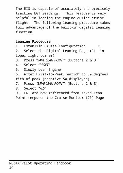
The EIS is capable of accurately and precisely tracking EGT readings. This feature is very helpful in leaning the engine during cruise flight. The following leaning procedure takes full advantage of the built-in digital leaning function.
Leaning Procedure1. Establish Cruise Configuration2. Select the Digital Leaning Page (“L” in lower right corner)3. Press “SAVE LEAN POINT” (Buttons 2 & 3)4. Select “RESET” 5. Slowly Lean Engine6. After First-to-Peak, enrich to 50 degrees rich of peak (negative 50 displayed)7. Press “SAVE LEAN POINT” (Buttons 2 & 3)8. Select “YES”
N604X Pilot Operating Handbook 36
9. EGT are now referenced from saved Lean Point temps on the Cruise Monitor (CZ) Page
N604X Pilot Operating Handbook 37
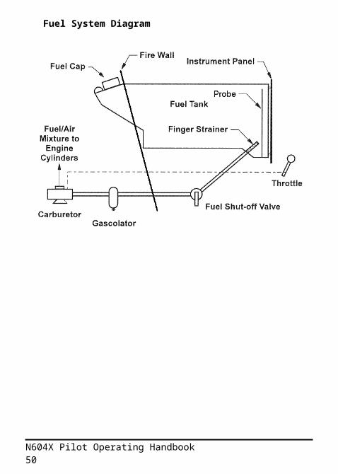
Fuel System Diagram
N604X Pilot Operating Handbook 38
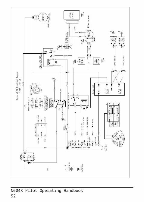
Electrical System Diagram
N604X Pilot Operating Handbook 39
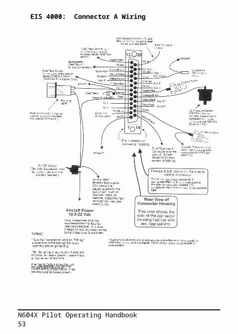
EIS 4000: Connector A Wiring
N604X Pilot Operating Handbook 40

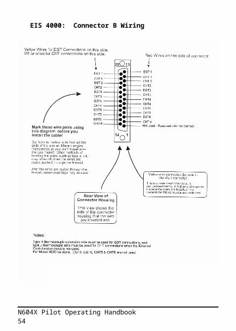
EIS 4000: Connector B Wiring
N604X Pilot Operating Handbook 41
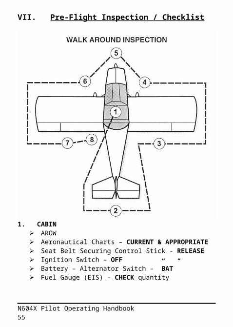
VII. Pre-Flight Inspection / Checklist
1. CABIN AROW Aeronautical Charts – CURRENT & APPROPRIATE Seat Belt Securing Control Stick - RELEASE Ignition Switch – OFF Battery – Alternator Switch – ”BAT” Fuel Gauge (EIS) – CHECK quantity Flight Instruments – SET – Analog + EIS Altimeter Flaps – DOWN Battery – Alternator Switch – ”OFF” Fuel Handle – ON (forward/parallel) for fuel sump
N604X Pilot Operating Handbook 42
2. EMPENNAGE Control Surfaces – CHECK for movement & security Empennage Fairing – CHECK for security Elevator Trim – CHECK for movement & security Rudder Cables – CHECK for security Tail Tie-Down – REMOVE Tail Wheel – CHECK for condition Tail Wheel Pushrod – CHECK for security
3. RIGHT WING Aileron – CHECK for movement & security Flap – CHECK for security
4. RIGHT FRONT Wing Tie-Down – REMOVE Wheel Chock – REMOVE Main Wheel Tire – CHECK for proper inflation Gear Leg Fairing – CHECK for security
5. NOSE
N604X Pilot Operating Handbook 43
Engine Oil Level – CHECK – 2 quarts minimum Propeller & Spinner – CHECK for nicks & security Cowl Fasteners & Hinge Pins – CHECK for security Cooling Inlets – CHECK for obstructions Fuel Tank – CHECK visually for quantity Fuel Tank Cap – CHECK for security Fuel Tank Vent – CHECK for obstruction Gascolator Sump – DRAIN sump 4 seconds Exhaust – CHECK for security
6. LEFT FRONT Wing Tie-Down – REMOVE Wheel Chock – REMOVE Pitot/Static Tube – REMOVE cover – CHECK for
obstruction Main Wheel Tire – CHECK for proper inflation Gear Leg Fairing – CHECK for security
7. LEFT WING Aileron – CHECK for movement & security Flap – CHECK for security
8. COCKPIT Canopy – CHECK for condition Canopy Latch – CHECK for operation and security Fuel Handle – CHECK off (back/perpendicular) for
starting
N604X Pilot Operating Handbook 44
VIII. Normal Procedures
BEFORE STARTING ENGINE Preflight Inspection – COMPLETE Passenger Briefing – COMPLETE Seat Belts & Shoulder Harnesses – ADJUST & LOCK
STARTING ENGINE Fuel Shutoff Valve – ON Battery – Alternator Switch – ”BAT” Throttle – “CRACKED” OPEN approx. ¼” Flaps – UP Mixture – Push RICH; Wait 2-3 seconds to prime Brakes – ENGAGED to “park” Propeller Area – CLEAR Ignition Switch – ”START” EIS – CHECK for alerts Oil Pressure – CHECK Battery – Alternator Switch – ”ALT” Throttle – 1600 RPM for engine warm up
BEFORE TAKE-OFF Fuel Shutoff Valve – ON Flight Controls – FREE & CORRECT Elevator Tim – SET TO MIDDLE Elevator Trim – NEUTRAL Throttle – 2000 RPM Engine Run-up – CHECK MAGS – 100 RPM drop on
each Mixture – FULL RICH (forward) Engine Instruments – CHECK Throttle – 1000 RPM Flight Instruments – SET Radio – SET Seat Belts – ADJUST & SECURED Canopy – CLOSED & LATCHED
N604X Pilot Operating Handbook 45
NORMAL TAKE-OFF Brakes – HOLD Throttle – FULL “OPEN” Brakes – RELEASE Elevator – slightly tail high Engine RPM – 3100 RPM minimum Climb Speed – 70-80 MPH
MAXIMUM PERFORMANCE TAKE-OFF Throttle – FULL “OPEN” Elevator – LIFT TAIL Airspeed – ROTATE at 60 MPH*
* 65 MPH with 2 people on board Engine RPM – 3100 RPM minimum Climb Speed – 70 MPH (Vx)
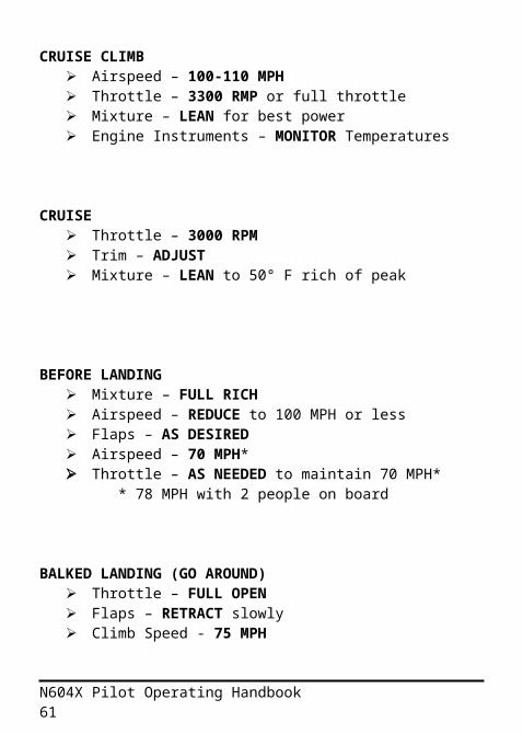
CRUISE CLIMB Airspeed – 100-110 MPH Throttle – 3300 RMP or full throttle Mixture – LEAN for best power Engine Instruments – MONITOR Temperatures
CRUISE Throttle – 3000 RPM Trim – ADJUST Mixture – LEAN to 50° F rich of peak
N604X Pilot Operating Handbook 46
BEFORE LANDING Mixture – FULL RICH Airspeed – REDUCE to 100 MPH or less Flaps – AS DESIRED Airspeed – 70 MPH* Throttle – AS NEEDED to maintain 70 MPH* * 78 MPH with 2 people on board
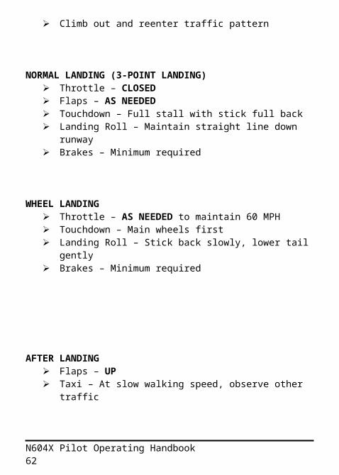
BALKED LANDING (GO AROUND) Throttle – FULL OPEN Flaps – RETRACT slowly Climb Speed - 75 MPH Climb out and reenter traffic pattern
NORMAL LANDING (3-POINT LANDING) Throttle – CLOSED Flaps – AS NEEDED Touchdown – Full stall with stick full back Landing Roll – Maintain straight line down runway Brakes – Minimum required
WHEEL LANDING Throttle – AS NEEDED to maintain 60 MPH Touchdown – Main wheels first Landing Roll – Stick back slowly, lower tail gently Brakes – Minimum required
N604X Pilot Operating Handbook 47
AFTER LANDING Flaps – UP Taxi – At slow walking speed, observe other traffic
ENGINE SHUTDOWN Throttle – 1000 RPM for engine cool down BAT/ALT Switch – ”BAT” MAGS – CHECK for cut-off Mixture – IDLE CUT-OFF (pulled full out)
After Engine Stops MAGS – ”OFF” Fuel Shutoff Valve – ”OFF” BAT/ALT Switch – ”OFF”
Note: Failure to close fuel shutoff valve may result in fuel flowing from the AeroCarb after shut-down.
SECURE AIRCRAFT Brakes – ENGAGED to “park” as required Master & MAG Switches – CHECK OFF Fuel Shutoff Valve – CHECK “OFF” Throttle – FULL CLOSED Mixture – IDLE CUT-OFF (pulled full out) Cockpit – CLEAN & SECURE Seat Belt – SECURED around control stick Canopy – LATCHED AND LOCKED Pitot Tube – INSTALL COVER as required Wheel Chocks – INSTALL as required Wing & Tail Tie-Downs – INSTALL as required
IX. EMERGENCY PROCEDURES
N604X Pilot Operating Handbook 48
POWER LOSS ON TAKEOFF Stick – FORWARD Airspeed – 70 MPH Throttle – CLOSE Mixture – IDLE CUT-OFF Fuel Valve – OFF Master & MAG Switches – OFF Flaps – AS REQUIRED Land and/or Stop Straight Ahead Brakes – AS REQUIRED
POWER LOSS IN FLIGHT TRIM FOR BEST GLIDE – 70 MPH Note Wind Direction & Velocity PICK A LANDING SPOT Mixture – FULL RICH Fuel Valve – ON MAGS – ON Master – ON Engine – CHECK EIS
If Power Not Restored & Time Permits Maintain Best Glide – 70 MPH Radio – 121.5 – CALL MAYDAY Mixture – IDLE CUT-OFF Fuel Selector – OFF Master – OFF Flaps – AS NEEDED Canopy – UNLATCH Seat Belts & Shoulder Harnesses – PULLED TIGHT Land Tail Low
N604X Pilot Operating Handbook 49
ROUGH ENGINE Mixture – ADJUST Fuel Selector – ON MAGS – CYCLE SWITCHES Run On Best Settings Locate Suitable Landing Site & Land ASAP Prepare For Off Field Landing If Necessary
OIL PRESSURE LOSS Locate Suitable Landing Site & Land ASAP Prepare For Off Field Landing If Necessary
HIGH OIL TEMPURATURE Reduce Power Increase Airspeed Observe Trend
If Oil Temperature Cannot Be Stabilized Locate Suitable Landing Site & Land ASAP Prepare For Off Field Landing If Necessary
ENGINE FIRE DURING START-UP Throttle – FULLY OPEN Starter – CRANK Mixture – IDLE CUT-OFF Fuel Selector – OFF Master and MAG Switches – OFF
ENGINE FIRE IN FLIGHT Throttle – CLOSED Mixture – IDLE CUT-OFF Fuel Selector – ON Master & MAG Switches – OFF Locate Suitable Landing Site & Land ASAP
N604X Pilot Operating Handbook 50
X. SERVICING REQUIREMENTS
Exterior Care
N604X is painted with Loehle Aero Coatings urethane paint system. The exterior coat is Loehle urethane clear coat. The paint may be washed with mild soap and waxed with automotive waxes as desired.
Windshield and Canopy Care
The windshield and canopy are standard plexiglas acrylic. Care must be taken to keep the plexiglas clean and unscratched. Flush away grit with water to prevent scratching, then wash with water with mild detergent or commercial plexiglas cleaner, such as Novus or Plexus. Never use benzene, gasoline, alcohol, acetone, carbon tetrachloride, lacquer thinner or glass cleaner to clean plastic. These materials will damage the plastic and may cause severe crazing.
Brakes
N604X uses Azusa mechanical drum brakes, and machined aftermarket drums, purchased through Sonex Aircraft. The brake pads are integral to the unit, and can only be removed through disassembly. Pads should be checked for wear annually. Normal brake pad life is estimated at 500 hours.
Propeller
The Sensenich propeller is a composite coated, laminated wood propeller. It is extremely durable, and resistant to
N604X Pilot Operating Handbook 51
corrosion and damage. Re-torque propeller bolts every 50 flight hours, every 6 months, or with drastic seasonal changes. Proper torque is 145 inch-lbs, +/-15 inch lbs. Place the propeller in a horizontal position when not in use. Routine cleaning can be accomplished with mild detergents.
Tires
Nankang/Shin 11-400x5 6-ply tires and tubes are used. Tires should be replaced when the remaining tread depth reaches 1/16”. Inflate tires to a pressure of 50 PSI. Use of higher tire pressures is not recommended due to loss of shock absorption and increased wear of the tires. Clean and repack the main wheel bearings after the first 100 hours, then every 200 hours thereafter.
Battery
The Odyssey PC625 battery is a high performance, sealed lead-acid 12 volt battery. It is rated at 16 amp-hours, and 625 cranking amps for 5 seconds. Under normal conditions, no servicing or maintenance is required. The battery cable terminals, lugs, and wires should be inspected annually for security and corrosion.
Fuel and Oil Requirements
The AeroVee engine is rated for 92 Octane Automotive fuel, including up to 10% ethanol. Aviation grade 100LL fuel may also be used, and may be combined with auto fuel in any proportion. Addition of TCP lead scavenger fuel additive is recommended when using 100LL fuel for extended periods of time, and will help prevent lead buildup inside the engine. Auto fuel, especially fuel containing alcohol, is susceptible to vapor lock in warm climates. Blending auto fuel with 25%-
N604X Pilot Operating Handbook 52
50% 100LL will greatly reduce the potential for vapor lock and/or detonation from insufficient octant rating, and is a recommended practice for ambient temperatures greater than 90º.
Automotive 20W-50 multi-grade oil (Pennzoil or Castrol GTX) is used year round, although fully synthetic (Mobile 1 15W-50) or synthetic blends may be substituted for added protection. Lighter weight oils may be used in colder climates if hard starting occurs. In very cold temperatures (<20 F), 10W-30 multi-grade oil may be substituted. Engine pre-heat is recommended when temperature is below 40º Fahrenheit to save unnecessary wear and tear. Oil change is recommended every 25 to 30 hours of operation, or every 4 months. No oil filter is used on the AeroVee engine.
The aircraft is equipped with a fuel gascolator attached to the lower right side of the firewall. Inside the gascolator is a fine-mesh wire screen designed to filter out debris and contaminants. This screen should be inspected and cleaned every 100 hours, or annually. Replace screen as needed.
Spark Plugs
Spark plugs (Autolite MP4163) should be cleaned, tested, and re-gaped every 100 hours, or annually. Ensure CHT probe ring terminals are properly placed between the plug body and the sealing crush washer, not between the washer and the head. Apply anti-seize lubricant and re-torque plugs to 240 in-lbs. Using 100LL avgas may result in lead deposits forming on the plug electrodes. Replace plugs as needed, or every 200 hours.
Carburetor Air Filter
N604X Pilot Operating Handbook 53
Replace the carburetor air filter every 50 hours, or as needed. To remove the air filter, remove the engine cowl and unscrew the retaining bolt on the filter housing. Replacement filter elements are available from Sonex Aircraft (PN ACV-C10-33). Alternately, a K&N high performance filter (PN E-3120) may be directly substituted.
N604X Pilot Operating Handbook 54
XI. Equipment List
Updated September 29, 2006
Engine: AeroVee 2180 SN: 258
Starter: Sky-Tech Model: 122-12AVSN: A2X-140524
Oil Cooler: B&M Supercooler Model: 15K GVWJegs PN: 130-70265
Carburetor: AeroCarb Model: ACV-C03SN: 5541P
Air Filter: K&N Model: E-3120
Propeller: Sensenich 55x44 Model: W54LVG-44GSN: AG-1605
Battery: Odyssey PC625 Catalogue Number: 0768-0001
ELT: AmeriKing – AK-450 ELT
Air-Oil Separator: Aircraft Spruce Oil Breather PN: 10570
Airspeed Indicator: UMA
N604X Pilot Operating Handbook 55
UMA 3-1/8 ASI, 40-200MPHAircraft Spruce PN: 10-01029
Altimeter: Falcon Falcon Sensitive AltimeterBarometric Pressure Correction20,000 ft, Inches, 3 1/8”Model: ALT20INF-3SN: 05010008
Compass: Danforth Quest Low Profile DomeModel: C100
Comm: Narco 11A
Fuel Probe: Princeton Electronics Capacitance Fuel ProbeModel: FL-PE-05
Engine Info System: Grand Rapids Technologies
Model: 4000SN: SW Version:
Parameter HI LOOil Pressure 80 psi
20 psiOil Temp 220F 160F
Voltage 14.0 12.4Fuel Qty ---- 3 galRPM 3600 ----EGT 1400 ----CHT 430 ----
Tach EMP setting 5
N604X Pilot Operating Handbook 56

XII. Passenger Disclaimer Form[To be read and signed by all passengers before flight]
I, acknowledge having been informed that:
1. The Sonex aircraft, N604X, is an Experimental aircraft;Airworthiness of this aircraft cannot be certified. However, but maintained by the owner to the best of his knowledge and ability.
2. The aircraft is for recreational use only, and may not be operated for remuneration. Passengers are taken as an act of friendship and courtesy, and at their own risks.
3. Risks are inherent to experimental aircraft operation.
I hereby:4. Indemnify the owner/operator and his next of kin for any loss or damage occurred during operation.
5. Declare that I have not made any financial arrangement with the owner/operator with regards to payment of the flight, except for voluntary sharing of the aircraft operating cost, which is limited to fuel cost and airport fees.
Made at ___________ , this _ day of _
_ [Signed]
N604X Pilot Operating Handbook 57

XII. Revisions List
Rev # Description Date1 Revised W&B 17 Dec
062 Revised Electrical System Diagram 20 Jan 073 Added EIS 400 Connector Diagrams 22 Apr
074 Revised Service Requirements,
Equipment List (added EIS settings), and minor formatting changes
22 Sep 07
5 EIS description and functions added to Systems section, revised performance section, adjusted desired CHT & EGT temps, added approved 15W-50 synthetic oil, updated approved fuel and grade, and minor formatting changes; Aerobatic Gross weight adjusted to 950 lbs as per Sonex LLC.
04 Jan 08
6 Updated Performance Graphs 26 Mar 08
7 Added Section IV: Engine Operation; revised performance figures
03 May 08
8 Updated “time, Distance, and Fuel to Climb” performance table.
19 Aug 08
N604X Pilot Operating Handbook 58
Notes
N604X Pilot Operating Handbook 59
N604X Pilot Operating Handbook 60
Notes
N604X Pilot Operating Handbook 61
Notes
N604X Pilot Operating Handbook 62