Embed Size (px)
Citation preview

Studies in Big Data 47
N. JeyanthiAjith AbrahamHamid Mcheick Editors
Ubiquitous Computing and Computing Security of IoT

Studies in Big Data
Volume 47
Series editor
Janusz Kacprzyk, Polish Academy of Sciences, Warsaw, Polande-mail: [email protected]

The series “Studies in Big Data” (SBD) publishes new developments and advancesin the various areas of Big Data- quickly and with a high quality. The intent is tocover the theory, research, development, and applications of Big Data, as embeddedin the fields of engineering, computer science, physics, economics and life sciences.The books of the series refer to the analysis and understanding of large, complex,and/or distributed data sets generated from recent digital sources coming fromsensors or other physical instruments as well as simulations, crowd sourcing, socialnetworks or other internet transactions, such as emails or video click streams andothers. The series contains monographs, lecture notes and edited volumes in BigData spanning the areas of computational intelligence including neural networks,evolutionary computation, soft computing, fuzzy systems, as well as artificialintelligence, data mining, modern statistics and operations research, as well asself-organizing systems. Of particular value to both the contributors and thereadership are the short publication timeframe and the world-wide distribution,which enable both wide and rapid dissemination of research output.
More information about this series at http://www.springer.com/series/11970

N. Jeyanthi • Ajith AbrahamHamid McheickEditors
Ubiquitous Computingand Computing Securityof IoT
123

EditorsN. JeyanthiSchool of Information Technologyand Engineering
VIT UniversityVellore, Tamil Nadu, India
Ajith AbrahamScientific Network for Innovationand Research Excellence
Machine Intelligence Research Labs(Mir Labs)
Auburn, WA, USA
Hamid McheickUniversité du Québec à ChicoutimiChicoutimi, QC, Canada
ISSN 2197-6503 ISSN 2197-6511 (electronic)Studies in Big DataISBN 978-3-030-01565-7 ISBN 978-3-030-01566-4 (eBook)https://doi.org/10.1007/978-3-030-01566-4
Library of Congress Control Number: 2018957051
© Springer Nature Switzerland AG 2019This work is subject to copyright. All rights are reserved by the Publisher, whether the whole or partof the material is concerned, specifically the rights of translation, reprinting, reuse of illustrations,recitation, broadcasting, reproduction on microfilms or in any other physical way, and transmissionor information storage and retrieval, electronic adaptation, computer software, or by similar or dissimilarmethodology now known or hereafter developed.The use of general descriptive names, registered names, trademarks, service marks, etc. in thispublication does not imply, even in the absence of a specific statement, that such names are exempt fromthe relevant protective laws and regulations and therefore free for general use.The publisher, the authors and the editors are safe to assume that the advice and information in thisbook are believed to be true and accurate at the date of publication. Neither the publisher nor theauthors or the editors give a warranty, express or implied, with respect to the material contained herein orfor any errors or omissions that may have been made. The publisher remains neutral with regard tojurisdictional claims in published maps and institutional affiliations.
This Springer imprint is published by the registered company Springer Nature Switzerland AGThe registered company address is: Gewerbestrasse 11, 6330 Cham, Switzerland

Contents
Security Protocols for IoT . . . . . . . . . . . . . . . . . . . . . . . . . . . . . . . . . . . 1J. Cynthia, H. Parveen Sultana, M. N. Saroja and J. Senthil
Security of Big Data in Internet of Things . . . . . . . . . . . . . . . . . . . . . . . 29Rakesh Bandarupalli and H. Parveen Sultana
IoT for Ubiquitous Learning Applications: Current Trends andFuture Prospects . . . . . . . . . . . . . . . . . . . . . . . . . . . . . . . . . . . . . . . . . . 53Salsabeel Shapsough and Imran A. Zualkernan
Trust Management Approaches in Mobile Adhoc Networks . . . . . . . . . 69R. Vijayan and N. Jeyanthi
Security in Ubiquitous Computing Environment: Vulnerabilities,Attacks and Defenses . . . . . . . . . . . . . . . . . . . . . . . . . . . . . . . . . . . . . . . 101C. Shoba Bindu and C. Sasikala
v

Security Protocols for IoT
J. Cynthia, H. Parveen Sultana, M. N. Saroja and J. Senthil
Abstract The Internet of Things (IoT), is a network of devices that are uniquelyidentified and has embedded software required to communicate the transient statesand data that are usually used to trigger an actuator. The edge networking devices andprotocols are used to communicate with a cloud server that processes and aggregatesthe big data arriving from various devices, performs analytics and aids in businessdecisions. IoT has become an integral part of today’s industrial, agriculture, health-care and smart city revolution. Securing all entities involved in an IoT network isvital as it involves pervasive data collection and dissemination. Current IoT protocolswork with IP protocols as backbone, but they are specially designed to operate inmultiple layers and provide security at various layers. This chapter focuses on IoTprotocols that deals with securing an IoT network. The major challenges in securingan IoT network is lack of standardization at manufacturing level which exposes thehardware, software and the data to various threats and attacks. The IoT protocols haveto deal with security breaches at the site of the cloud service provider and the securityissues pertaining to data privacy, authentication, authorization and trust managementin a distributed heterogeneous environment. This chapter also elaborates on varioussecurity attacks and the solutions offered by IoT protocols.
Keywords IoT security · IoT architecture · IoT protocols · IoT threatsIoT attacks · Heterogeous
1 IoT Introduction and Security Overview
There are over billions of IoT devices, business process and systems with an IoTelement in it. This dormant data available in the eco system must be trapped and
J. Cynthia · M. N. Saroja · J. SenthilKumaraguru College of Technology, Coimbatore, India
H. Parveen Sultana (B)VIT University, Vellore, Tamil Nadu, Indiae-mail: [email protected]
© Springer Nature Switzerland AG 2019N. Jeyanthi et al. (eds.), Ubiquitous Computing and Computing Security of IoT,Studies in Big Data 47, https://doi.org/10.1007/978-3-030-01566-4_1
1

2 J. Cynthia et al.
analyzed to see if any functional information that is of benefit to a customer orbusiness could be retrieved. Essential elements of IoT are people, things, data andprocess. IoT systems aims at networking these elements that communicates witheach other through wired or wireless medium. IoT devices are grouped as sensorsthat collect data, Actuators that effect actions and gateways that act as interface forcommunication and automation. In an IoT framework, data is gathered from sensors,processed by microcontrollers such as Raspberry Pi or Arduino, stored in a clouddatabase and data analytics from big data gathered is performed using any tool orlanguages such as python or java. IoT is designed to strengthen communicationacross Device to Device (D2D), Human to Device (H2D), Human to Human (H2H)and Device to Human (D2H).
IoT has led to numerous autonomous applications in the area of health care,business solutions, smart city, home automation, industry automation and intelligenttransport system. The success of IoT lies in distributed data gathering, aggregation,processing and analytics that can be performed from any location and is usually doneas a cloud service. IoT system evolves with flow of data from the sensor from whereit is acquired to the service that processes and performs analytics on the data acquiredto the customer or business that makes use of the analytics information.
With prevalent presence of IoT, security risks are in rise. Making data availableanywhere makes it vulnerable to security threats and attacks. This chapter deals withmajor issues, challenges and solutions for providing IoT security. A single com-promised entity in an IoT network makes other entities vulnerable. Since IoT isa collection of devices or sensors networked together to a cloud in order to pro-vide information service, all security threats that are applicable for Wireless SensorNetworks (WSN), internet and cloud are pertinent to IoT networks. IoT opens uptremendous opportunity for business with the associated risk. Absence of strongauthentication of IoT devices, encryption of IoT data, key management, etc., makesan IoT network vulnerable to external attacks and threats.
2 IoT Security Requirements
Security must be addressed throughout the lifecycle of an IoT device. Shipley [1] andJing et al. [2] lists security requirements to be checked at various stages of the lifecycle in order to alleviate an IoT attack. IoT security requirements are listed below,
• Cryptographic Algorithms—Symmetric algorithms are light weight compared toasymmetric algorithms and hence were recommended for securing data transmis-sion. However, they have problems in key exchange, confidentiality, digital signa-ture andmessage authentication. Hence public key algorithms were recommendedas they were able to provide key management, node authentication, scalability andsecurity.
• Key Management Techniques—Key management is an important security featurein IoT. Light weight secure key distribution is required for secure communication.

Security Protocols for IoT 3
Key distribution schemes used in WSN are broadcast, group, node master andshared key distribution [2]. The focus on key management research is to reducethe complexity, power consumption and security.
• Secured routing algorithms—Traditional network routing protocols cannot beapplied for IoT network. The routing protocol must ensure authenticity of routedinformation and eaves dropping must be avoided while communicating throughwireless medium. Routing protocols should be secured to prevent attacks such asDos, Worm hole, black hole and selective forwarding.
• DataClassification—The data floating in an IoT network could be either functionalor connected to people or an enterprise. The degree of protection required for adata depends on the degree of sensitivity of the data. Data may be protected basedon sensitivity classification [3]. Hence following recommendation is made for anIoT vendor,
– To define a data classification scheme based on data sensitivity.– Identify all data and data groups in an IoT network and classify them.– Design a security feature that protects viewing and editing of data based on itsclassification level.
• Protecting devices at production time—The IoT devices may be protected at pro-duction time. Any interface used at production time must be removed beforedeployment. All ports to the IoT devices must have proper access control. Devicesplaced in exposed locations must have a tamper proof covering and shielding toavoid side channel attacks [3].
• Trusted and staged boot sequence—A trusted staged boot sequence will ensuresecurity of an IoT device. However, the first sequence is vital and hence should beinitiated by secured locked code. Use of secure module where the cryptographicalgorithms and associated keys are stored are recommended. At every stage ofboot code, it is recommended to check the trust worthiness of boot code, validityof hardware and completion of previous code.
• Secured operating system—An IoT operating system should have limited accessrights and reduce the visibility of the system. The operating system should bedesigned so as to have only the components, packages and libraries required forrunning an IoT device. Throughout the lifetime of the deployed device the updatemust be provided. The ports, protocols and services that are not used are to bedisabled. Have separate access rights for user and administrators to access the filesand directories must be given. An encrypted file system is to be used.
• Application security—Security considerations must be an integral part of appli-cation development and should not be added separately. The application gatewayshould validate all gathered data before it is getting processed. All user accountsand passwords are to be relinquished. Credentials from application has to be sep-arated into a secured storage. Any application errors should not reveal detailsabout the underlying architecture. Use of secured software development life cycleprocedure is recommended.
• Credential management—Credentials such as passwords, cryptographic keys anddigital certificates of user and process that are used to access the data must be kept

4 J. Cynthia et al.
in secured location that cannot be accessed by external entities. The passwordsused for authenticating must be strong, encrypted and must have industry standardhash function. Two factor authentications may be used for access control. Uniquedigital certificate for each device is recommended and this certificate must besecured and updated at regular intervals.
• Encryption—Strongest and latest encryption is recommended for an IoT network,if it is affordable. The encryption standard should be in correlation with the sensi-tiveness of the data to be protected. Use of global keys is to be avoided. The privatekey of a device should never be shared. The encryption keys should be able to bereplaced remotely. The encryption keys must be stored in trusted key modules.
• Network connections—The number of interfaces to an IoT device through whichit gets connected to the external networkmust be kept as minimal. The device mustbe able to be accessed only through minimal port, interface and services. Secureprotocols such as https and SFTP to protect connections are to be used. Receivermachine must be authenticated before sending any sensitive data.
• Software updating—Before any software updation, authentication of the sourcethat authenticates, must be done with help of a verified certificate obtained from aauthenticated certification authority. The software update packagesmust be signed.
• Secured event logging—The event logging should be protected from hackers, frombeing modified or deleted. The event logs are normally stored in a centralized logpool away from the IoT device and hence must be transmitted though separatechannels. The logs must be periodically analyzed to detect any faults and imme-diate action is to be taken. The log files must be stored in separate partitions in filesystem. Access rights to the log file are to be restricted. No sensitive credentialssuch as passwords are to be stored in logs.
3 IoT Security Issues
The issues associated with security of IoT are not only the issues related with securityof wireless medium, WSN and internet, but also access control, authentication andprivacy issues associated with IoT.
• Low power embedded device—IoT devices have less computation power andstorage capacity. It is often found embedded in a bigger hardware or wearabledevice where it is difficult to execute security algorithms that are normally heavyweight and expensive for a resource constrained device.
• Trust Management—Trust management is required for data authentication datagathering and dissipation phases for which strong cryptographic techniques ordigital signatures are recommended [2].
• Heterogeneity—IoT is an integration of various heterogeneous networks and hencehas its own compatibility and security issues. It is difficult to identify trusted nodesin a heterogeneous environment. Heterogeneity, identity management, privacyfault tolerance [3].

Security Protocols for IoT 5
• Secured Access control—Secured access control is a major challenge in an IoTnetwork. Usually the information in the cloud is accessed by various entities andprocess. Also the granularity level for accessing the same data differs for differentretrievers. Therefore, defining access control policy and securing the access is oneof the major challenges [3].
• Identity Management—It is required to uniquely identify an IoT device and pro-vide both authentication and authorization for each of the device. Authenticationensures the validity of the data that flows through the device and authorizationensures secured access control. The entities in an IoT network may be addeddynamically and hence identity management with authentication becomes evenmore difficult.
• Privacy—It is important to provide privacy for the billions of users in IoT networks.Anonymity of the user must be maintained. Access control list must be maintainedby any service provider. Privacy must be given its due importance in the entire IoTlife cycle.
• TrustManagement—Trustmanagement plays a vital role in communication acrossentities and between an entity and user. Reputation calculation is required to decideon a trusted entity. The collective view of a central entity helps in calculation ofreputation of the remaining entities. The inconsistencies in the reputation valuemay be resolved by sharing the trust information from various central entities.
• Distributed IoT Network—A centralized or connected IoT network has separatedata acquisition passive entities, which give the collected data to a centralizedcloud service that does the job of aggregating, processing, analyzing and distribut-ing. Moreover, the information flow to the central authority follows a hierarchicalpattern. This has better centralized security control but once subjected to vulnera-bility, the entire system is compromised. In a distributed IoT network every entityis entitled to do the job of data collection, processing, analyzing and distributinginformation and hence is an attack vector.But however an attackerwill be able to retrieve only the partial information from theattacked entity which may also be the vital information required. The edge intelli-gence at the service provider’s end to query the information by a local user withoutintervention from any external entity has a potential vulnerability which shouldbe controlled by providing strong authentication and authorization features [3].
4 IoT Security Challenges
Hossain et al. lists the challenges of IoT security based on limita-tions of hardware, software, network connections. The hardware lim-itations are, computational and energy constraint, memory constraintand tamper resistant packaging. Limitations on software are embedded soft-ware constraint and dynamic security patch. Limitations on network connectionsare mobility, scalability, multiplicity of devices and communication medium, multiprotocol networking and network topology.
6 J. Cynthia et al.
4.1 IoT Hardware
IoT hardware includes sensors, wearable devices, digital gadgets, microcontrollerslikeArduino,Raspberry pi and embeddedhardware. IoThardware devices are presentwith the customers, embedded in some other device and may be used as a wearabledevice or may be present connected to the internet all time. Therefore, these devicesare more vulnerable to security attacks and can be easily tampered with. Hardwaredevice manufacturers are more concerned in design aspect of IoT devices rather thanthe security aspect. Hence the customers are exposed to more risk [4]. The reducedsize and processing capability inhibits the security features of an IoT device [5]. Dueto the prevalent presence of IoT hardware it is difficult to provide a software patch forsecurity updates. Due to lack of standardization before manufacturing, also exposesthe IoT hardware to security threats. IoT hardware are exposed to attacks to whichall internet connected devices are exposed to such as DOS, and DDoS.
In order to protect the hardware, issues such as hardware lifecycle, softwareupdates, access control and device authentication should be dealt with. Enterprisesshould take initiative to check the configuration of all IoT devices, perform vulnera-bility scan and check network connections [6]. Embedded system security is a majorconcern for growth of IoT. Various IoT consortiums are working on defining a frame-work to implement identity, device discovery, authentication and security controlsin a consistent manner. Care should be taken to protect the private data present inhardware before they are discarded [7]. When choosing a hardware platform, thesecurity concerns such as its unique identity and secured storage for encryption keysare to be verified. Evaluation to be done to check how difficult it is to change thecredential stored in hardware.
4.2 IoT Software and Firmware
IoT software component includes the embedded software, operating systems used inIoT such as Android and Tiny OS, and cloud software such as Nimbis and Hadoop.Most of the IoT software deals with data gathering, integrating devices, applicationand process interface, and real time analytics. IoT devices connected to internet haveoperating system embedded as firmware. These operating systems are not designedwith security concerns and hence are vulnerable to malware attacks. The embeddeddata in appliances, mobile phones and wearable devices with networking capabilityare more vulnerable to external attack. This is because they share the data with otherconnected devices and the embedded data lives for more period than the hardwarethemselves. The security aspect is neglected by the enterprise as the cost of hardwareis much less than software and security upgrades. Improperly configured storagedevices connected to network and are used from home are also major source ofthreat. There is huge volume of data generated from these devices. It is difficult to

Security Protocols for IoT 7
decide if the data has to be protected or not. Trojan horse or worms may be used toinject malicious code into software.
The most cost effective solution for protecting the embedded software is to moni-tor and secure the traffic at gateway [8]. The securities threats for thewearable devicesused in health care and manufacturing sectors, can be minimized by disabling theirbluetooth communication, geo fencing the communication, restrict communicationand access control with external applications. Outdated operating system and soft-ware without a patch has to be avoided to ensure security.
4.3 Insecure Network Communication
Owing to the huge number of IoT devices connected to the network, tradition networksecurity, identity and key management mechanisms are difficult to implement. Anydevice or process attached to an IP address or URL has an associated risk with it. It isdifficult to bring the entire IoT device connected under the boundary of a controlledfirewall, because an attacker may use a single compromised node to attack the entirenetwork in a lateral manner. The monitoring and isolation of IoT devices involved tothe private VLAN or network segment may reduce security threat [8]. Mesh networkis suggested as a solution for connecting IoT devices, since it is Self-organizing, self-healing and scalable. Sudden increase in bandwidth requirement due to large volumeof data generated from social networking sites and IoTwill emulate the attack such asDoS. Wireless communication amongst IoT nodes subjects them to both active andpassive attacks. A mesh network is formed by connecting wireless devices withoutany infrastructure.Meshing in IoT enables the IoT elements to communicate amongstthemselves in absence of fixed infrastructure for communication. This is extremelyuseful in case of low power and low data rate applications in health care, industrialand home automation applications [9]. IoT network in an enterprise is subjectedto vulnerability, if proper Enterprise Mobility Management (EMM) policy is notdefined to mitigate the risk of vital corporate data leaked to the outside world.
4.4 Data Leaks from Cloud
Data is stored in a cloud with primary motive of sharing. Strongly authenticatedsources in the Access Control List are expected to access the data. A service provideris responsible for any data leakage from cloud. A misconfigured cloud will lead todata leakage. External access to sensitive data and logs must be restricted. A hostileemployee may gain access to any internal server and enterprises, outsource certainservices with potential threat of data leak. Cloud environment demands continu-ous monitoring and intrusion detection. It requires monitoring and logging virtualmachine logs and shared services. Intrusion detection and prevention systems arerecommended for cloud in order to avoid data leakage.

8 J. Cynthia et al.
4.5 Threats and Attack Vectors
The paper [7] indicates list of potential threats used by an IoT targeted attacker. Hemay use the MAC address to understand the target platform and reverse engineer thesoftware, to find the encryption keys. The attack vectors are path used by a hackerto gain access to a secured system [10]. As the attack vectors available for maliciousattackers are growing day by day because of the global connectivity and accessibility,fault tolerance must be provided. IoT data and meta data are potential attack vectorsfor any hacker. Following are some of threats in IoT,
• Denial of Service—A DoS attack in IoT is aimed at exhausting service providers’resources and network bandwidth. Channel jamming in wireless network is also atype of DoS attack. Since IoT devices are exposed to active attackers, it also leadsto DoS type of attack.
• Eaves dropping—Passive attackers target the communication channel and eavesdrop the data and extract the information. An active attacker may capture a nodeexposed to outside environment to gain access to the store data.
• Controlling IoT entity—An active attacker may gain control over an IoT entitythrough an attack path. This type of attack not only gains control of the data butalso the services that are associated with the data.
• MQTT Attack—IoT servers that use Message Queuing Telemetry Trans-port(MQTT) on internet is subjected to attack because of unauthenticated andunencrypted communication. MQTT servers are also vulnerable to SQL injectionand cross-side scripting. The MQTT servers used for firmware updates, may beused to update malicious code [11].
• Ransomware—IoT network are subjected to ransomware attack where they stealdata from any interface gateway or cloud aggregator and claimmoney for the same.In a ransomware attack, an attacker usually gets hold of critical data as in hospitalsthat is required for day-to-day activity of an organization and demands money insome form to release the data. A ransomware attack in an IoT environment causesbusiness loss.
• IoT Request Forgery—An attacker tries to target IoT devices connected to a cor-porate network rather than to crack several security layers.
• Wearable malware—The wearable devices acts as an attack vector of a mobilemalware attack and allows authorized access to a connected IoT network, botnetshave potential to attack IoT network as a group.
• Virtualization threats—The host machine running virtualization software could beattacked by code in virtual environment that simulates man in middle attack [12].
5 IoT Protocol Architecture
IoT protocol stack is not standardized as TCP/IP or OSI protocol suite. Most of theIoT security protocols are designed to operate in multiple layers to provide security.
Security Protocols for IoT 9
The protocols used and security measures provided depends on whether a node isconstrained or unconstrained [13].
Wireless Hart is a security protocol that operates in multiple layers using multiplekeys and secures the traffic by encrypting payload and providing message authenti-cation. Separate keys are used by network layer to authenticate end to end commu-nication and data link layer to authenticate hop to hop communication.
LoRaWAN is the long range variant that provides secured bidirectional commu-nication, mobility and localization services. It provides unique network key to ensuresecurity in network layer, unique application key to ensure end to end security inapplication layer and also a device specific key.
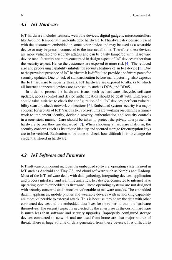
As described in [14] illustrates the protocols operating in all 5 layers of TCP/IPprotocol Stack, the IoT applications and associated services. Figure 1 illustrates theIoT architecture and protocol stack.
Physical Layer—This layer is data oriented and is responsible for collecting datafrom IoT devices. The issues to be considered in physical layer of an IoT networkare power, bandwidth and energy consumption. The devices attached to this layer aresusceptible to security challenges such as physical tampering of devices, eaves drop-ping and data altering. Cryptographic algorithms play a major role in physical layersecurity. Low power Wide Area Network (LPWAN) is used in IoT for transmissionof small data over long range with battery efficiency. It uses modulation techniquesuch as ultra-narrow band, narrow band and wide band. IoT connectivity technology
Fig. 1 IoT architecture and protocol Stack

10 J. Cynthia et al.
may be chosen based on capacity of channel, QoS, reliability, range, battery life,security, cost and standard [15].Data Link layer—Increasing the transmission power also increases the data ratein wireless communication. Any wireless communication protocol such as Blue-tooth, Wi-Fi, Zig bee may be used. IEEE802.15.4 is used to provide link layersecurity. It protects MAC frames using symmetric key cryptographic techniques.This includes Zigbee, 6LoWPAN, Wireless-HART. Weightless is a standard usedfor exchanging data between base stations and several IoT devices in a securedfashion. EAP(Extensible Authentication Protocol) supports multiple authenticationmethods and runs independent of IP.Network Layer—In network layer, security is usually provided by 6LoWPAN andIPSec protocols. A constrained node uses 6LoWPAN and an unconstrained deviceused IPv6 for addressing in IoT. 6LoWPAN is specifically designed to provide secu-rity in devices with low power and computing ability inWSN and internet. Therefore,cryptographic algorithms combine RSA and ECC techniques. 6LoWPAN must beaccompanied by IDS techniques to monitor traffic for any malicious behavior [16].CCN (Content concentric Networking) is a protocol used to deliver content as pack-ets and has been designed to deal with scalability, mobility and security. IP Sec(Internet Protocol Security) is designed to provide authentication of sender data andencapsulating security payload to provide data encryption and sender authentication.Transport Layer—QuiC [13] protocol provides multiplexed connections over UDPand provides security protection similar to TLS/SSL in order to reduce connectionlatency. DTLS (Datagram transport Layer) protocol offers communication privacybetween client and server. It prevents eaves dropping, tampering and forgery. IPSecin transport layer ensures confidentiality and integrity.Application Layer—The application layer security issues include user authentica-tion, privacy, access control, middle ware security. A constrained node uses CoAPand an unconstrained node uses HTTP as application layer protocol. A constrainednode is also authenticated by the gateway. An unconstrained node entrusts the job ofmaster session key generation and authentication to the trusted gateway. The crypto-graphic keys are generated and exchanged based on Elliptic Curve—Deffie Hellmankey exchange. AMQP (Advanced Message Queuing Protocol) is a protocol for mes-sage oriented middleware that is designed to take care of message queuing routing,reliability and security.
Open Trust Protocol (OTrP) is a protocol to install, update, and delete applicationsand to manage security configuration in a Trusted Execution Environment (TEE).X.509 is a standard for public key infrastructure (PKI) to manage digital certificatesand public-key encryption.Akey part of theTransport Layer Security protocol is usedto secure web and email communication. Table 1 [17] describes various protocolsstack, attacks and defenses in WSN.

Security Protocols for IoT 11
Table 1 LLN protocol stack, threats and defense
Layer Attack Defense
Physical Jamming Channel surfing, spatial retreat, priority messages
Radio interference Delayed disclosure of keys
Tampering Tamper proofing, hiding
MAC Collission Error-correcting code
Exhaustion Rate limitation
Unfairness Small frames
Network Sink-hole Geo-routing protocol
Worm-hole, black hole Authorisation, monitoring redundancy
Homing Encryption
Misdirection Egress filtering, authorisation, monitoring
Transport De-synchronisation Authentication
Flooding Client puzzles
Application Overwhelm Rate-limiting
Reprogram Authentication
6 IoT Security Attacks
Internet of Things, the increasing need in our day-to-day life has more advantages.The important thing about IoT is, it makes the things beings intelligent by embeddingsensors and actuators. By increasing the connectivity, it enables new services. On theother side, the amount of data generated by IoT is getting increased which results insecurity attacks.
Well, most of the people can think of
• Why Security is more important in IoT?• What can a person do by attacking the device?• Why is it important to consider the attack on device?• Is it possible for my device to provide private data to intruders?
These are the questions will come to mind, when anyone think of security in IoT.Let me explain one by one.
Internet of things has a variety of sensors, wearable devices, mobile phones andhome appliances. Most of the time, the devices are produced by the manufacturerswho doesn’t know about the security. Also, he is not a security expert too. Whena user stores a private data such as mail passwords, bank details etc. in his mobile,he usually thinks that it is stored in his local memory. Actually it is stored in cloudstorage. This will help the hacker to easily attack the data from the cloud and misuseit. In this way, the security in IoT is considered to be more important.
What may be the next question is usually, people will store data only in theirmobile phones, then why there is a need to protect sensor devices and other homeappliances?

12 J. Cynthia et al.
The thing is, when a device, say a security camera connected to a home is attacked,the hacker can clearly know the possibility of robbing a house. This will inviteunknown persons to home also.
Let me explain with another example. When a refrigerator which orders thingsneeded for a smart home got hacked, he may order any number of things or he maygenerate a spam to randomly generate more things. In this situation, the user willeither will lose money for things he has not ordered or will get irritated and switch offthe device. The important thing is, the device which has been attacked is connectedto our mobile phones and other devices also. So, when a simple device is attacked,the hacker can easily gain access to devices which contain secure data. This is thereason why security is considered to be important in IoT.
The next thing, we have to discuss is what are all the ways through whichthings/devices can be attacked. The various attacks that can be performed arefirmware attack, data attack, telnet based attacks, denial of service attack. Let meexplain them one by one.
6.1 Attacks on Firmware
Firmware is nothing but software used to control hardware devices. In the early 90 sitself, the firmware attack has been started. In general, firmware is stored in non-volatile memory. Hackers generally add some malicious code to this non-volatilememory and make it as a part of firmware and start controlling the device. Anotherreason why people prefer firmware attack is, they are harder to detect since they runbefore the antivirus program starts.
Hackers attack firmware for three main reasons [18]:
1. Persistence: Malwares can be cleared often using antivirus software, whereasfirmware is not.
2. Protection: Mechanisms such as antivirus software’s will not examine firmwareso that it can be hidden and used for a long time.
3. Authorization: Being a part of firmware by adding malicious code, the user canget complete authorization for accessing the system.
The advantagewith firmware attack is that the firmware software is obsolete often.Also, most of the people are unaware about updating device software. Of course, themanufacturer of a device is not an expert in security, which results in vulnerabledevice.
Do you think that the latest firmware will provide complete security? If you sayyes, then it is your false sense about security. In reality, most of the devices which aremanufactured recently are equippedwith the operating systemwhich is a decade ago.Also it was not maintained by Security professions which results in easier attacks.
If everything is negative, how to overcome this type of attack? Is it not necessaryto update the software?

Security Protocols for IoT 13
No, it is not so. The best suggestion which I could offer in this place is throughupdating the devices and keeps them up-to-date. Next thing is we, the consumers candemand the manufacturers to provide better security device. This can be done onlywhen IT professionals, industry and security experts work together.
6.2 Attacks on Data
IoT enables more and more devices to be connected which results in more securityvulnerabilities. The devices that are connected (as shown in Fig. 2) may include eachand every object which we use in our day-to-day life.
We will store data from temperature to our sensitive data such as passwords. Isthat protected over there?
No. We think that how a connected object can provide information. Consider asurveillance camera which records the data of a terrorist attack. If a person can hackit easily, he can change the records. Do you now understand the importance of data?Again, you may wonder that a surveillance camera is that much easier to attack? Itmay be protected, but the router connected to it or a sensor connected to it can easilybe attacked. This way, the Internet of Things provide more options for the hackers
Fig. 2 Connected objects in IoT

14 J. Cynthia et al.
Fig. 3 Estimated no. of connected devices
to steal information. The estimated number of devices as per CISCO estimation mayreach 50 billion by 2020 as shown in Fig. 3. If almost every device is vulnerableto attack, the world will not exist. If every data can be hacked by simple means, itdoesn’t make sense to be connected.
Letme explainwith another example. You have stored your banking details (sensi-tive data) in your mobile phones. You think it is protected by passwords, fingerprintsetc. so that it cannot be attacked. But when you are trying to control a fan (in Smarthome—an IoT Application), using your mobile phone, it actually happens by meansof a sensor. If sensor is hacked, then automatically malicious code is transferred tomobile devices which make it easier to attack. Now, do you think it is not possi-ble? You cannot. The Internet of Things makes the things getting connected but alsoprovide many security holes.
6.3 TELNET Based Attacks
This is an important topic in IoT. People will think Telnet is very old and what isthere to be important in it. Hackers have changed the trend to use old techniques toattack new technologies. There is where the concept of Telnet comes. Telnet actuallyprovides a gateway for attacking the internet of things. IBMSecurity has also releaseda research titled “Beware of Older Cyber Attacks” [19]. In that article, it is clearlyhighlighted that Telnet, a very old technique to access remote systems can be usedas a key to gain access into unauthorized access.
Many embedded system applications leverage its remote access capabilities. If anattacker can find a open telnet port, then he can perform the following:

Security Protocols for IoT 15
• Exploit any vulnerabilities associated with the device• Gain unauthorized access to a device for stealing data• Determine how the information is shared between devices• Perform brute force attacks to gain passwords.
One example of this kind of attack is the Bricker Bot attack. The Bricker bot attackused Telnet Brute force attack to breach Victim’s devices. Bricker Bot attack wasdesigned to record the first attempted username and password. Through that, it willgain access to the devices connected to it. The attack can be blocked by disablingTelnet and changing the default passwords.
Another reasonwhy telnet is important ismost of the deviceswill be having defaultusername and passwords. Even though people using the devices are instructed tochange the passwords, it not clear that everybody does the same. The entire passwordsare not changed. Such devices can be easily provided with remote access throughTelnet and SSH.
6.4 DDOS Attack
Denial of Service Attack is another important attack in case of Internet of Things.Denial of Service attack generates more traffic to the server and overloads it whichresults in the service being rejected. If the DoS attack is performed with huge botnet,then it is called Distributed Denial of Service Attack. IoT botnets comprises of webcamera’s, TV, DVR, Setup boxes etc. to launch the DDoS Attack.
On 20 September 2016 [20, 21], “KrebsOnSecurity.com” [22] became the targetof a massive DDoS attack that eventually knocked the site offline. The site wasinitially protected from this attack by Akamai, the website’s digital security serviceprovider. The company decided to withdraw its pro bono protection shield, since themagnitude of the attack (approximately 620 Gbps) was too vast to bear it withoutaffecting other customers. Akamai’s analysis indicated the use of a large botnet ofcompromised IoT devices. Upon Akamai’s protection withdrawal, the website wentoffline until Google offered its DDoS attack mitigation service, Project Shield, torevive it.
OVH, a well-known Web hosting provider, was also a victim of an even moremassive DDoS attack than the one that hit “Krebs on Security”. According to a tweetfrom OVH founder Octave Klaba on 22 September 2016, a simultaneous DDoSattack of 990 Gbps (combined) was launched by a botnet consisting of more than145,000 compromised IoT devices (IP cameras and DVRs). OVH reported that itwithstood the attack.
Right after the DDoS attacks against “KrebsOnSecurity.com” and OVH, a useron a hacking forum released the source code of a malware dubbed “Mirai”. Themalware targets unprotected IoT devices and turns them into bots. The attacker isthen able to launch a DDoS attack commanding all bots through a central commandand control server as done in common botnets.

16 J. Cynthia et al.
On 21 October 2016, the DNS provider Dyn, experienced a massive DDoS attackand initially claimed that the attack originated from tens of millions of IP addressesaround the world. A later update from Dyn, noted that malicious endpoints wereactually estimated to be around 100,000. The attack caused issues to certain userstrying to reach popular websites such as Twitter, Amazon, Tumblr, Reddit, Spotifyand Netflix throughout that day. According to Dyn’s information on the Incident partof the attack involved IoT devices infected by the Mirai botnet. After several hoursand several waves of attacks Dyn resolved the incident.
The main things about the massive IoT DDoS attacks are as follows:
1. Huge amounts of traffic at DNS servers made many websites to stop working.2. Botnet is formed by large number of unsecured devices such as home routers and
surveillance cameras.3. Use of default passwords is one of the main reason for this vulnerability.
What can be done to secure from these things? I suggest you with the followingsolutions:
• Update IoT devices with security patches as soon as patches become available.• Disable Universal Plug and Play (UPnP) on routers unless absolutely necessary.• Purchase IoT devices from companies with a reputation for providing securedevices.
6.5 roBOT+NETwork (BOTNET)
IoT botnets are not new. A Botnet is a logical connection of compromised devicessuch as routers, smart phone or IoT devices. These compromised devices can becontrolled and used for performing DDoS attacks. The objective of creating a botnetis to infect as many devices as possible. Generally, IoT botnets have been usedto launch high-profile DDoS attacks against online gaming networks, to engage inDDoSextortion attempts, and to target organizations affiliatedwith theRioOlympics.
Some of the notable botnet attacks are Zeus malware, Srizbi botnet, GameoverZeus etc. The Zeusmalware used a Trojan horse program to infect vulnerable devicesand created a Zbot which can be used to harvest banking credentials and financialinformation. Srizbi botnet again used Trojan horse program. The Gameover Zeusbotnet would generate domain names to serve as communication points for infectedbots. An infected device would randomly select domains until it reached an activedomain that was able to issue new commands
Mirai malware is designed to scan the internet for insecure connected devices,while also avoiding IP addresses belonging to major corporations, like Hewlett-Packard and government agencies, such as the U.S. Department of Defense. Onceit identifies an insecure device, the malware tries to log in with a series of commondefault passwords used by manufacturers. If those passwords don’t work, then Miraiuses brute force attacks to guess the password. Once a device is compromised, it

Security Protocols for IoT 17
connects to C&C infrastructure and can divert varying amounts of traffic toward aDDoS target.
Devices that have been infected are often still able to continue functioning nor-mally, making it difficult to detect Mirai botnet activity from a specific device. Forsome internet of things (IoT) devices, such as digital video recorders, the factorypassword is hard coded in the device’s firmware, and many devices cannot updatetheir firmware over the internet.
The Mirai source code was later released to the public, allowing anyone to usethe malware to compose botnets leveraging poorly protected IoT devices.
6.6 Malware
Malware is again software used to gain access to a device and infect them. Most ofthe IoT attacks are performed either by using a Trojan horse program or malware.BrickerBot attack and Mirai botnet are all created by adding a malicious softwarecode to it. According to a report provided by Kaspersky lab [23], more than 8.5million malware attacks have been performed during 2015 and 2016.
Why are these devices so vulnerable to malware infection? A number of reasons,but primarily because manufacturers have hastily created insecure products in theirrush to benefit from the financial opportunities made abundant by inexpensive IoTtechnology. Under pressure to be competitive and quickly bring products to market,security has received very little attention. As a result, IoT devices commonly sufferfrom:
• Weak authentication: Passwords and login credentials are frequently left in theirdefault state, many of which are weak and easily guessed. Some devices havesolitary, fixed passwords, or virtually no authentication requirements whatsoever.
• Numerous security vulnerabilities: In many cases, products are designed by engi-neers with very little security expertise. History has repeatedly shown that all codehas vulnerabilities. Software that’s hastily developed or produced under extremebudget pressure has, even more, vulnerabilities.
• Limited upgrade capabilities: Inexpensive devices, like many IoT products, oftenhave very low-profit margins, which can make it difficult or even impossible formanufacturers to afford to update firmware or send security patches.
• Limited encryption: A significant percentage of IoT devices are completely voidof any encryption, either in transit or at rest.
• Not on the security radar: Not very many IT security personnel spend any energyregarding the security of smart thermostats, security cameras, DVRs, vendingmachines, or other “gadgets” connected to the company’s network.
Malware infected smart gadgets are capable of inflicting harm in a number ofways, including the following:
• Denial of Service attacks
18 J. Cynthia et al.
• Ransomware attacks• Identity theft• Account takeover• Theft of IP.
It’s time for enterprises to take IoT security seriously, and implement policiesand tools to detect advanced malware that already has, or is attempting to estab-lish a foothold in their organization. By investing a reasonable amount of time andeffort to thwart IoT malware now, businesses will be much better prepared for theever-increasing number of vulnerable devices that will surely be connecting to theirnetworks.
7 IoT Security Solutions
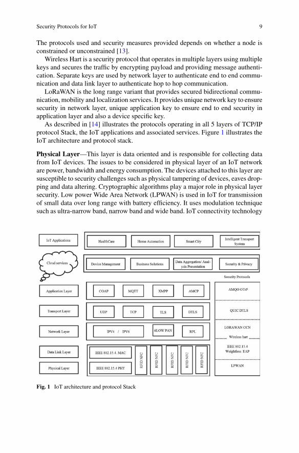
In the previous section, we briefly discussed about the possible attacks that can beperformed on an IoT device. In this section, we will discuss about the protocol stackof IoT architecture, various protocols that supports the architecture and the varioussolutions to enhance the security of IoT devices. The protocol stack of IoT [24] is asshown in Fig. 4.
Since, the Internet of Things consist of many connected devices such as sensorsand RFID tags, it is important to adapt these devices to operate in a conventionalinternet. IoT devices are often constrained in computing power andmemory capacity.Therefore it is a challenge to use cryptographic algorithms which often need moreresources than the tiny devices have all together. Another challenge is updatingdevices in the field. There is often only an unreliable connection available and securitycritical things call for immediate updates, which can be difficult to roll out to all
Fig. 4 IoT protocol stack

Security Protocols for IoT 19
devices at once. Additionally the challenge of making security intuitive for the user ismore relevant than ever, because the acceptance of users depends on easy installationand maintenance. Let me explain the protocols and security solutions that can beoffered in IoT with various layers (Transport, Network and Application layers).
7.1 Transport Layer Solutions
The transport layer mainly involves two types of protocols. One is TCP and anotherone is UDP. In addition to these protocols, other protocols like Secure SocketLayer, Datagram Transport Layer Security and Quick UDP Internet Connectionsare explained to brief about the security in transport layer.
7.1.1 Transmission Control Protocol (TCP)
TCP is one of the widely used transport layer protocol where reliability is a majorconcern. TCP works on the principle of 3-way handshaking process. It has a connec-tion establishment phase, data transmission phase and connection termination phase.This helps to achieve reliable data transfer. TCP is a connection oriented protocol.It determines how to break the application data into packets such that the networklayer can easily process. Due to network congestion, some packets may get lost. TCPdetects these problems and retransmits it.
The header format of the TCP [25] is as follows in the Fig. 5.In this header, we have to separate field, namely checksum to ensure whether the
received data is correct or not. But it doesn’t provide any security mechanism to
Fig. 5 TCP header format
20 J. Cynthia et al.
prevent stealing of data. The security can be added with TCP in terms of SSL orTLS, which we will discuss in the subsequent sections.
7.1.2 Secure Socket Layer (SSL)
TCP does not provide any security to data. In order to transfer private data, SSL hasbeen introduced. SSL uses a cryptographic system that uses two keys to encrypt thedata—public key and private key.
When a Web browser tries to connect to a website using SSL, the browser willfirst request the web server identify itself. This prompts the web server to sendthe browser a copy of the SSL Certificate. The browser checks to see if the SSLCertificate is trusted—if the SSL Certificate is trusted, then the browser sends amessage to the Web server. The server then responds to the browser with a digitallysigned acknowledgement to start an SSL encrypted session. This allows encrypteddata to be shared between the browser and the server.
Even though SSL provides security, it is still prone to Man-in-the middle attacks.To overcome the problems with SSL, we move to TLS.
7.1.3 Transport Layer Security (TLS)
SSL, or Secure Sockets Layer, is the predecessor to TLS, or Transport Layer Security.SSL has three versions, which are all considered insecure due to flaws in their design.TLSwas created to address the weaknesses in the SSL protocol. The terms SSL, TLSand SSL/TLS are commonly used interchangeably in literature.
TLS is a protocol that provides privacy and data integrity between two commu-nicating applications. It’s the most widely deployed security protocol used today,and is used for Web browsers and other applications that require data to be securelyexchanged over a network, such as file transfers, VPN connections, instant messag-ing and voice over IP.
Key differences between SSL and TLS that make TLS a more secure and effi-cient protocol are message authentication, key material generation and the sup-ported cipher suites, with TLS supporting newer and more secure algorithms. TLSand SSL are not interoperable, though TLS currently provides some backward com-patibility in order to work with legacy systems.
Although TLS provides security, it id found that it has kept the connection aliveevenwhen no data is being transmitted. TLS is not vulnerable to the POODLE attack,because it specifies that all padding bytes must have the same value and be verified, avariant of the attack has exploited certain implementations of the TLS protocol thatdon’t correctly validate encryption padding. This makes some systems vulnerableto POODLE, even if they disable SSL—one of the recommended techniques forcountering a POODLE attack. The IETF is working on the issue and still it is a draft.

Security Protocols for IoT 21
7.1.4 User Datagram Protocol (UDP)
In contrast to TCP, yet another protocol namely UDP has been designed. It is a con-nectionless protocol. It has no handshaking dialogues, and thus exposes the user’sprogram to any unreliability of the underlying network protocol. There is no guar-antee of delivery, ordering, or duplicate protection. UDP provides checksums fordata integrity, and port numbers for addressing different functions at the source anddestination of the datagram.
When compared with TCP, UDP is preferred for IoT devices due to minimaloverhead. In many resource-constrained embedded designs, UDP’s lack of overheadmakes a big difference in throughput when compared to TCP. UDP is connectionlessand, therefore without a connection state to be maintained, so memory size/usageis not much of an issue. And because a UDP transaction requires only two UDPdatagrams, one in each direction, load on the network is minimized, further reducingresponse times.
7.1.5 Datagram Transport Layer Security (DTLS)
DTLS is a communications protocol that provides security for datagram-basedapplications by allowing them to communicate in a way that is designed to pre-vent eavesdropping, tampering, or message forgery. The DTLS protocol is basedon the stream-oriented Transport Layer Security (TLS) protocol and is intended toprovide security guarantees. TheDTLS protocol datagram preserves the semantics ofthe underlying transport—the application does not suffer from the delays associatedwith stream protocols, but has to deal with packet reordering, loss of datagram anddata larger than the size of a datagram network packet
DTLS consists of two layers: the lower layer contains the Record protocol andthe upper layer contains any of the three protocols namely Handshake, Alert, andChange Cipher Spec, or application data. The Change Cipher Spec is used duringthe handshake process to merely indicate that the Record protocol should protect thesubsequent messages with the newly negotiated cipher suite and security keys. DTLSuses the Alert protocol to communicate the error messages between the DTLS peers.The Record protocol is a carrier for the upper layer protocols. The Record headercontains among others content type and fragment fields. Based on the value in thecontent type, the fragment field contains the Handshake protocol, Alert protocol,change Cipher Spec protocol, or application data. The Record header is primarilyresponsible to cryptographically protect the upper layer protocols or application dataonce the handshake process is completed. The Record protocol’s protection includesconfidentiality, integrity protection and authenticity.
The DTLS Record is a rather simple protocol whereas the Handshake protocolis a complex chatty process and contains numerous message exchanges in an asyn-chronous fashion. The handshake messages, usually organized in flights, are used tonegotiate security keys, cipher suites and compression methods. The scope of this
22 J. Cynthia et al.
paper is limited to the header compression only and not the cryptographic processingof Record and Handshake protocols.
7.1.6 Quick UDP Internet Connections (QUIC)
Quic is another multiplexed stream oriented protocol over UDP. Quic is designed toprovide security equivalent to SSL/TLS. The main goal of this protocol is to improvethe performance when compared with TCP.
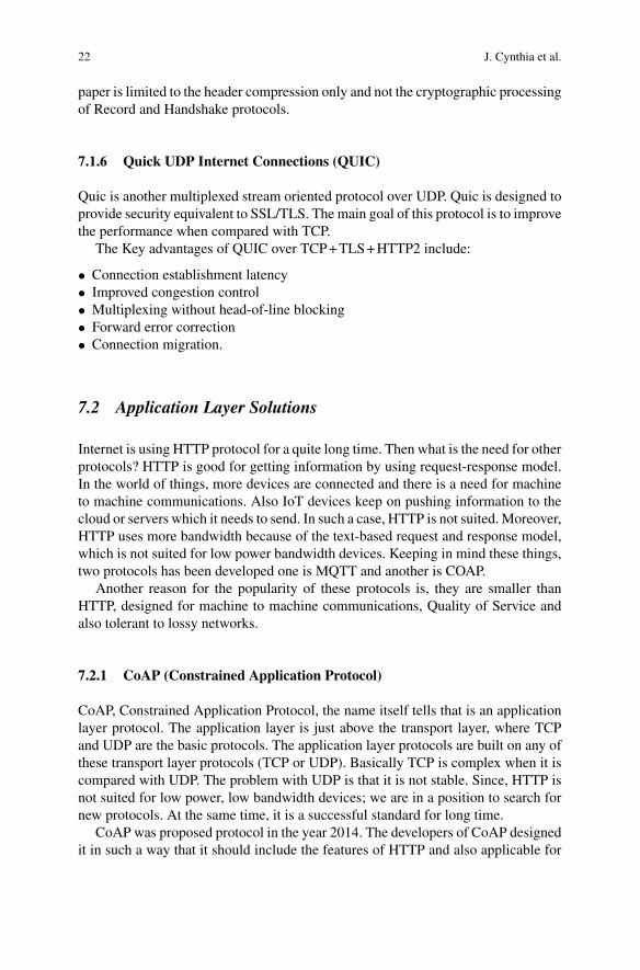
The Key advantages of QUIC over TCP+TLS+HTTP2 include:
• Connection establishment latency• Improved congestion control• Multiplexing without head-of-line blocking• Forward error correction• Connection migration.
7.2 Application Layer Solutions
Internet is using HTTP protocol for a quite long time. Then what is the need for otherprotocols? HTTP is good for getting information by using request-response model.In the world of things, more devices are connected and there is a need for machineto machine communications. Also IoT devices keep on pushing information to thecloud or servers which it needs to send. In such a case, HTTP is not suited. Moreover,HTTP uses more bandwidth because of the text-based request and response model,which is not suited for low power bandwidth devices. Keeping in mind these things,two protocols has been developed one is MQTT and another is COAP.
Another reason for the popularity of these protocols is, they are smaller thanHTTP, designed for machine to machine communications, Quality of Service andalso tolerant to lossy networks.
7.2.1 CoAP (Constrained Application Protocol)
CoAP, Constrained Application Protocol, the name itself tells that is an applicationlayer protocol. The application layer is just above the transport layer, where TCPand UDP are the basic protocols. The application layer protocols are built on any ofthese transport layer protocols (TCP or UDP). Basically TCP is complex when it iscompared with UDP. The problem with UDP is that it is not stable. Since, HTTP isnot suited for low power, low bandwidth devices; we are in a position to search fornew protocols. At the same time, it is a successful standard for long time.
CoAP was proposed protocol in the year 2014. The developers of CoAP designedit in such a way that it should include the features of HTTP and also applicable for

Security Protocols for IoT 23
Fig. 6 CoAP messagestructure
constrained devices. CoAP operates over UDP and is based on REST architecture.The CoAP message structure is shown in the Fig. 6.
CoAP employs a two layer structure, where the layers are Messages andRequest/Response. Themessage layer comprises of CON (Confirmable), NON (non-confirmable), ACK (acknowledgement) and RST (reset). It is meant for retransmit-ting the lost packets.
1. CON (Confirmable)—when reliability is required, use this type of message. Inthis case, the messages are responded back with acknowledgement
2. NON (non-confirmable)—when reliability is not a big issue then use this3. ACK (acknowledgement)—This type is to ensure reliability4. RST (reset)—if something goes wrong, reset will be used.
The Request/Response layer contains methods like GET, PUT, POST andDELETE. CoAP protocol implements special features on HTTP which is not avail-able in HTTP. The features are
(i) Observe flag—InHTTP, it is complicated to know the unused state on a variable.This flag is used along with GET message. Whenever there is a change in theobserve flag, it will push the notification to the device
(ii) Discovery—This flag is related with discovering devices around us. The servercan store the list of devices and the media types that they support.
The Quality of Service is achieved with the help of Confirmable and Non-Confirmable messages.
To protect CoAP transmissions, Datagram TLS (DTLS) has been proposed as theprimary security protocol. Analogous to TLS protected HTTP (HTTPs), the DTLS-secured CoAP protocol is termed CoAPs. DTLS guarantees E2E security of different
24 J. Cynthia et al.
applications on a single machine by operating between the transport and applicationlayers.
7.2.2 MQTT (Message Queue Telemetry Transport)
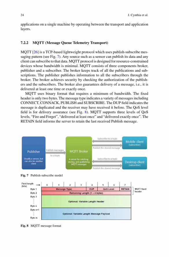
MQTT [26] is a TCP-based lightweight protocol which uses publish-subscribe mes-saging pattern (see Fig. 7). Any source such as a sensor can publish its data and anyclient can subscribe to that data.MQTTprotocol is designed for resource-constraineddevices whose bandwidth is minimal. MQTT consists of three components broker,publisher and a subscriber. The broker keeps track of all the publications and sub-scriptions. The publisher publishes information to all the subscribers through thebroker. The broker achieves security by checking the authorization of the publish-ers and the subscribers. The broker also guarantees delivery of a message, i.e., it isdelivered at least one time or exactly once.
MQTT uses binary format that requires a minimum of bandwidth. The fixedheader is only two bytes. The message type indicates a variety of messages includingCONNECT, CONNACK, PUBLISH and SUBSCRIBE. The DUP field indicates themessage is duplicated and the receiver may have received it before. The QoS levelfield is for delivery assurance (see Fig. 8). MQTT supports three levels of QoSlevels, “Fire and Forget”, “delivered at least once” and “delivered exactly once”. TheRETAIN field informs the server to retain the last received Publish message.
Fig. 7 Publish-subscribe model
Fig. 8 MQTT message format

Security Protocols for IoT 25
Not only it uses simple message format, but also requires less battery. MQTT wasoriginally created in 1999 for remote sensors. It is now used for secure and reliablecommunication between devices. MQTT is based on Transmission Control Protocol(TCP) and can be secured with Transport Layer Security (TLS). MQTT providesminimal security. MQTT communications that rely on TCP alone are unencryptedand susceptible to man-in-the-middle attacks, DDoS attacks and buffer overflowattacks.
Thenext problemwithMQTT is thatMQTTmessages are sent in clear text.Hence,the usernames and passwords are easy to access. To provide support to authenticationprocess, it relies on Transport Level Security (TLS). Transport encryption with SSLand TLS can protect data when implemented correctly. To protect against threats,sensitive data including user IDs, passwords, and any other types of credentialsshould always be encrypted. The downside of using TLS, SSL, and other methodsof encryption is that they can add significant overhead. However, techniques such asTLS session resumption can compensate for some of the connection costs of TLS.Hardware acceleration is another method for reducing the size penalty for encryp-tion. For complex applications over constrained devices, an optimized encryptionlibrary can be very useful. When application code is large, an encryption librarycan reduce the processing memory and increase performance. The architecture ofMQTT depends on brokers being highly available. Using X.509 certificates for clientauthentication can save resources on the broker side when many clients try to usebroker services—such as database lookups or web service calls. Combining MQTTwith state-of-the-art security standards like TLS and using X.509 certificates canalso help improve security and performance. The encryption of data for safety andprivacy is also critical to the revenue streams of service providers in delivering anoptimal customer experience.
Even though MQTT is designed to be lightweight, it has two drawbacks for veryconstrained devices. Every MQTT client must support TCP and will typically hold aconnection open to the broker at all times. For some environments where packet lossis high or computing resources are scarce, this is a problem.Also,MQTT topic namesare often long strings. Both of these shortcomings are addressed by the MQTT-SN(MQTT—Sensor Networks) protocol, which defines a UDP mapping of MQTT andadds broker support for indexing topic names.
7.2.3 Secure MQTT (SMQTT)
MQTT and MQTT-SN both use SSL/TLS for security. But in reality, providingsecurity certificates to all the devices is totally impossible. Also SSL/TLS suffersfrom attack such as BEAST, CRIME etc. To overcome this problem Secure MQTTwhich augments security feature for the existing MQTT protocol has been suggestedby the author in [27]. Various message types are used in this protocol and aredistinguished by message type in MQTT message header. Message type ‘0000’is reserved for future. Variable Header contains username and password flag (canfacilitate user authentication), upon setting them, corresponding values are also

26 J. Cynthia et al.
included in payload. However, these values are not encrypted in the message andhence not secure. SMQTT protocol augments security feature to the existing MQTTby proposing a new MQTT Publish message Spublish with reserved message type‘0000’, where the messages encrypted using ABE (Attribute Based Encryption).Publisher uses Spublish command to publish an encrypted message using ABE.Hence, Subscribers who satisfy the access policy are capable of decrypting themessage. The advantage of ABE is that it supports broadcast encryption which issuitable for IoT devices. ABE are of two types: (i) Ciphertext Policy based ABE(CP-ABE) and (ii) Key Policy based ABE (KPABE).
In secure MQTT protocol, there are three entities:
(i) Publisher device publishes the data under the given topic.(ii) Subscriber device receives the data under the same topic through a Broker.(iii) PKG or broker is the trusted third party.
There are four phases in the protocol. In setup phase, registration and key man-agement are done. During encrypt phase, data is encrypted and in publish phase,Publisher publishes encrypted data under the given topic name and sends it to thebroker. In decrypt phase, data is decrypted by subscribed devices.
7.3 Network Layer Solutions
The devices in the Internet of Things are resource constrained devices, which meansthe size of the device; the power and the memory capacity are limited. In this section,wewill discuss about the IPv6 and 6LowPANprotocols. IPv6 is to support the addressspace of all the IoT devices involved. 6LoWPAN is specially designed for low powerdevices.
7.3.1 IPv6
IPv4 is the network addressing used widely. It is a 32-bit address and can supportup to 4 billion devices. In the world of Internet of Things, every device is beingconnected to the Internet. But how is this possible? It can be done only when IPaddress is allocated to all the devices. IPv4 is not enough with such a huge numberof devices. So, we move to IPv6.
IPv6 is a 128 bit address. It can allocate up to 2128 range of address. This makesit possible to allocate all number of devices that are connected in the IoT world. Themajor features that makes it advantageous over IPv4 is as follows:
1. Scalability—Since it is a 128 bit address, we can allocate IP address to everydevice
2. True end-to-end connectivity can be achieved3. Address space utilization rates are small in IPv6

Security Protocols for IoT 27
4. IP Sec is a requirement in IPv6, which allows two or more hosts to communi-cate in a secure manner by authenticating and encrypting each IP packet of acommunication session.
7.3.2 6LoWPAN
Even though IPv6 provides the addressing platform, it is not suitable for the lowpower devices involved in IoT. To support these devices, we need another protocol.Low power Wireless Personal Area Networks (WPANs) which many IoT communi-cationsmay rely on have some special characteristics different from former link layertechnologies like limited packet size (e.g., maximum 127 bytes for IEEE 802.15.4),various address lengths, and low bandwidth. So, there was a need to make an adap-tation layer that fits IPv6 packets to the IEEE 802.15.4 specifications. The IETF6LoWPAN working group developed such a standard in 2007. 6LoWPAN is thespecification of mapping services required by the IPv6 over Low power WPANsto maintain an IPv6 network. The standard provides header compression to reducethe transmission overhead, fragmentation to meet the IPv6 Maximum TransmissionUnit (MTU) requirement, and forwarding to link-layer to support multi-hop delivery.Datagrams enveloped by 6LoWPAN are followed by a combination of some headers.These headers are of four types which are identified by two bits:
(00)—NO 6LoWPAN Header(01)—Dispatch Header(10)—Mesh Addressing(11)—Fragmentation.
ByNO 6LoWPANHeader, packets that do not accord to the 6LoWPAN specifica-tion will be discarded. Compression of IPv6 headers or multicasting is performed byspecifying Dispatch header. Mesh addressing header identifies those IEEE 802.15.4packets that have to be forwarded to the link layer. For datagrams whose lengthsexceed a single IEEE 802.15.4 frame, Fragmentation header should be used. 6LoW-PAN removes a lot of IPv6 overheads in such a way that a small IPv6 datagram canbe sent over a single IEEE 802.15.4 hop in the best case. It can also compress IPv6headers to two bytes.

28 J. Cynthia et al.
References
1. Shipley AJ (2013) Security in the internet of things, lessons from the past for the connectedfuture. Security Solutions, Wind River, White Paper
2. Jing Q, Vasilakos AV,Wan J, Lu J, Qiu D (2014) Security of the internet of things: perspectivesand challenges. Wireless Netw 20(8):2481–2501
3. Roman R, Zhou J, Lopez J (2013) On the features and challenges of security and privacy indistributed internet of things. Comput Netw 57(10):2266–2279
4. Veracode white paper—The internet of things: security research study. https://www.veracode.com/sites/default/files/Resources/Whitepapers/internet-of-things-whitepaper.pdf/
5. Hajdarbegovic N (2017) Are we creating an insecure IoT? Secure challenges and concerns.https://www.toptal.com/it/are-we-creating-an-insecure-internet-of-things
6. Lewis N (2015) Prevent IoT security threats and attacks before its too late. http://internetofthingsagenda.techtarget.com/tip/Prevent-IoT-security-threats-and-attacks-before-its-too-late
7. Absolute security. https://www.absolutesecurity.co.uk/8. Prevent enterprise IoT security challenges with preparation. http://internetofthingsagenda.tec
htarget.com/essentialguide/Prevent-enterprise-IoT-security-challenges-with-preparation9. Johnson S (2017) Using mesh networking to interconnect IoT devices. http://internetofthings
agenda.techtarget.com/feature/Using-mesh-networking-to-interconnect-IoT-devices10. Wheeler C (2017) Three new attack vectors that will be born out of IoT. https://www.liquidw
eb.com/blog/three-new-attack-vectors-will-born-iot/ [Three new attack vectors]11. Higginis KJ (2017) IoT devices plagued by lesser known security hole. https://www.darkread
ing.com/cloud/iot-devices-plagued-by-lesser-known-security-hole-/d/d-id/132932012. Mah P (2008) New attack vectors challenge IT security pros. http://www.techrepublic.com/bl
og/it-security/new-attack-vectors-challenge-it-security-pros/13. IoT standards and protocols. https://www.postscapes.com/internet-of-things-protocols/14. Manoharan V (2016) TCP/IP layer-wise IoT protocols. http://www.synapt-iot.com/blog/tcpip-
layer-wise-iot-protocols/15. LPWAN Technology Decisions: 17 Critical Features, Weightless STG (2016) http://www.wei
ghtless.org/membership/hvVs4ZGQqr5dwCDlBiYX16. Protocol,W.Name:AzamuddinRotationProject Title: Survey on IoT security.Chicago [Survey
on IoT security]17. Hossain MM, Fotouhi M, Hasan R (2015) Towards an analysis of security issues, challenges,
and open problems in the internet of things. In: 2015 IEEEWorld Congress on Services (SER-VICES). IEEE, pp 21–28
18. http://www.darkreading.com/iot/5-tips-for-protecting-firmware-from-attacks/d/d-id/132560419. http://safewayconsultoria.com/wp-content/uploads/2016/05/Beware-of-older-cyber-attacks_2
016-1.pdf20. https://www.welivesecurity.com/2016/10/24/10-things-know-october-21-iot-ddos-attacks/21. https://www.enisa.europa.eu/publications/info-notes/major-ddos-attacks-involving-iot-dev
ices22. http://krebsonsecurity.com/23. www.symtrex.com/category/iot24. Sutaria R, Govindachari R (2013) Making sense of interoperability: protocols and standard-
ization initiatives in IOT. In: 2nd International Workshop on Computing and Networking forInternet of Things
25. NetworkWolves (2015) https://networkwolves.wordpress.com/2015/03/20/tcp-and-udp-and-difference-between-them/
26. MQTT basics in IoT. http://www.rfwireless-world.com/Terminology/MQTT-protocol.html27. Singh M, Rajan MA, Shivraj VL, Balamuralidhar P (2015) Secure mqtt for internet of things
(iot). In: 2015 fifth international conference on Communication Systems and Network Tech-nologies (CSNT). IEEE, pp 746–751
28. ConnectedConsumer Product Best PracticeGuidelines (2016) IoT security Foundation. https://iotsecurityfoundation.org/wp-content/uploads/2016/12/Connected-Consumer-Products.pdf

Security of Big Data in Internet of Things
Rakesh Bandarupalli and H. Parveen Sultana
Abstract Presently 25 billions of devices are connected to the internet, and 50billions of devices will connect to the Internet by 2020. These devices comprise oflots of sensors. These sensors, computers, tablets, and smart phones are generatingtwice as much as the data today as they generated two years ago. According toa survey, 90% of connected devices are collecting the information, and 70% ofthis data is transmitting without encryption. The rapid growth of the data bringstremendous changes in the humans’ daily life. This data is providing new businessopportunities. Many IoT devices are generating data related to the personal behavior.Lots of research is happening in big data security. This research is in the initialstage only. Up to right now, there is no specific method for providing security tothe big data. Most of the data generated with IoT applications is unstructured data.Providing security to theunstructureddata ismoredifficult than theproviding securityto the structured data. This chapter discusses various mechanisms for providingsecurity to the big data generated by various IoT devices. This chapter describesthe existing techniques for providing security at data generation, transmission andstorage phases. The first methodology describes security to the data on Internetof Vehicles. This methodology uses a single sign-on algorithm. In this techniquevehicle node and slink nodes need to register at a big data center for one time. Thistechnique uses symmetric key cryptographic algorithms for encrypting the data. Thesecond methodology describes providing the security with a dynamic prime numberbased security verification scheme. In this methodology, the prime numbers willbe generated at regular intervals of time. The prime numbers will be generated atboth source and receiver side. 128-bit symmetric key cryptography is used for thismethodology. This paper also discusses about the advantages and disadvantages ofthese methodologies.
R. BandarupalliSree Vidyanikethan Engineering College, Tirupathi, Andhra Pradesh, Indiae-mail: [email protected]
H. Parveen Sultana (B)VIT University, Vellore, Tamil Nadu, Indiae-mail: [email protected]
© Springer Nature Switzerland AG 2019N. Jeyanthi et al. (eds.), Ubiquitous Computing and Computing Security of IoT,Studies in Big Data 47, https://doi.org/10.1007/978-3-030-01566-4_2
29

30 R. Bandarupalli and H. Parveen Sultana
Keywords Internet of Vehicle (IoV) · Secure mechanism · Big data · Large-scaleIoT · Big data analytics1 Introduction
The computational capability is increasing drastically from the past decade. Thedevelopment of networking is leading towards the rapid growth of the web technolo-gies and data centers [1]. The development of Internet of things and big data is quicklyaccelerating and impacting all areas of technologies. This enhancement is benefitingmany organizations as well as individuals [2]. The IoT devices are playing a vitalrole in this enhancement. The Big Data can be categorized depending upon threefactors Velocity, Volume, and Variety. Gartner introduced these terms to describe thechallenges of big data [3]. Massive opportunities are producing by analyzing this IoTdata in the domain of smart cities, smart transportation, health care and much more.
The rapid growth of IoT devices triggers big data analytics as a challenging task.According to the estimation of IDC (International Data Corporation), the big datamarket will reach more than the US$125 billion by 2019. The big data analyticsused to extract the useful information using various data mining techniques [4]. Thisinformation is useful in taking the business decisions aswell as in revealing the recenttrends.
The IoT data is different from the big data collected through the systems. Asthe IoT data is collected from various sensors, this data consists of a lot of noise,heterogeneity, and variety [1]. Various studies said that the sensors will increase to1 trillion by 2030. This enhancement will cause the producing of huge amounts ofdata [3]. The area like smart traffic, smart grids, intelligent logistics managementand intelligent buildings are the some of the applications of IoT and Big Data.
Big data is a term refers to large data sets. These data sets are complex in nature.The traditional data processing applications are not suitable for processing the data[2]. The big data consists of both structured as well as unstructured data. The data isgenerated from various sources like social networking sites, health care applications,and sensor networks and from many other organizations.
Internet of things is envisioned as the emerging trend. There is a lot of scope forresearch. This technology makes the human life comfortable. It shows solutions tothe lot of problems related to logistics, transportation, urbanization, and environment.This technology enables to connect the physical world things and cyber world.
2 Introduction to Internet of Things and Big Data
2.1 Internet of Things
IoT is a platform where the devices are communicated with one another over theinternet. These devices consist of various types of sensors. The IoT devices will sharethe information in a convenient manner. The IoT is termed as the next generation

Security of Big Data in Internet of Things 31
Fig. 1 Internet of Things big picture
revolution. IoT is adopted in various sectors such as smart cities, smart transportation,smart office, smart retail, smart energy and smart health care.
Figure 1 is representing the Internet of Things Big picture. It consists of variouscommunication mechanisms used in IoT, Different IoT gateways, different storagemechanisms used for storing the data produced by IoT devices and also variousapplications that use Internet of Things.
The mobile devices, transportation vehicles, home appliances, health care devicesetc. are used for data actuation [3]. Wrist watches, Doors, refrigerators, air condi-tioners and microwave Owens are the some of the IoT devices. These devices aredeployed in various geographical locations [5]. These devices will acquire the realtime data. These devices are connected with several communication mechanismssuch as Bluetooth, Zigbee,WiFi etc. 50 billion devices such as laptops, smart phones,sensors will connect to the internet.
The graph in Fig. 2 is generated from the data provided by Cisco in the year of2011. That graph is representing how the IoT devices are increasing rigorously inthis decade.
Figure 3 is representing that by 2020 50 billion connected devices will be avail-able for 7.6 billion people, and also the above figure is showing that the IoT is thecombination of people, devices, and sensors interconnected with one another.
2.2 Big Data
The IoT devices and various other software applications will produce the data contin-uously. This data will consist of Structured, Unstructured and Semi structured data.

32 R. Bandarupalli and H. Parveen Sultana
Fig. 2 Growing of Internet of Things
Fig. 3 Connected world
This huge amount of data is termed as “Big Data”. The conventional data bases arenot sufficient to store this huge amount of data [6]. In simple terms, the big data canbe defined as the data that cannot be handled by the single system. The conventionaldata bases cannot be used for processing and analyzing this data that is growingrigorously.
Gartner proposed a model consisting of 3V’s (Volume, Velocity, Variety). In otherwords Volume of the data producing, Variety of the data producing, Velocity orspeed of the data producing [1]. Some investigations said that the volume is the maincharacteristic of the big data.

Security of Big Data in Internet of Things 33
2.3 Big Data Analytics
The big data analytics examines large data sets consisting of a variety of data toprovide useful business information, market trends. By analyzing this huge amountof data can help the organizations in getting the useful information. Big data analyticsrequire tools and technologies that can transform structured, unstructured and semistructured data into more useful data [4–6]. The scientists can analyze large volumesof big data using the traditional tools.
2.4 Relationship Between Big Data Analytics and IoT
The big data analytics are used for decisionmaking by analyzing the data produced byIoT devices continuously. The big data analytics are used to analyze the continuousdata and store this large amount of data using various storage technologies. Thislarge amount of data mostly consists of unstructured data [7]. Here the analytic toolsneed to analyze this data with lightning speed so that the business organizationscan take the decisions immediately. Need of adopting big data in Internet of Thingsapplications are increasing dramatically. Figure 2 is representing how the big dataand IoT are interdependent on one another. As the usage of IoT devices is increasingthe use of the big data will also increase proportionally [8–10]. The combinationsof these two technologies are providing good business opportunities in the area ofbusiness and research.
Figure 4 is representing that how the big data analytics and Internet of Thingsare inter connected with one another. The Figure consisting of three phases, the firstphase consists of IoT devices with sensors, these devices are interconnected with oneanother [11–14]. The second phase consists of different storage technologies. Thedata produced by IoT devices are stored on low-cost commodity hardware. This datacan be called as big data, this data has mainly three properties i.e. volume, velocity,and variety. This data will be distributed among fault tolerant databases. The thirdphase is an analytical phase. In this phase, various tools will be used for analyzing thedata such as MapReduce, Spark, Skytree, and Splunk. These tools require trainingdata set. With the help of training data sets we use queries, then produce reports andresult sets.
2.5 Architecture of IoT for Big Data Analytics
The architecture in Fig. 5 is representing the Architecture of Internet of thing for Bigdata analytics. This architecture is consisting of seven layers. The first layer consistsof IoT deviceswhich are having sensors. The second layer consists of communicationdevices such as Internet, Zigbee, WiFi, and Bluetooth etc.

34 R. Bandarupalli and H. Parveen Sultana
The internet of things connects all manner of end-points,unraveling a treasure trove of data
Ubiquitousnetworks and deviceproliferationenable access to a massive and growing amount of traditionally soiled information
Analytics and business intelligence tools empower decision makers as never before by extracting and presenting meaningful information in real-time, helping us be more predictive than reactive
IoT Big Data Analytics
Fig. 4 Relationship between Internet of Things and big data analytic
IoT Devices
NetworkDevices
IoT Gateway
CloudStorage
Big Data analytics
API Management Dashboard
Fig. 5 Architecture IoT for big data analytics

Security of Big Data in Internet of Things 35
The next layer is the cloud which is constructed with commodity hardware. Thedata generated by IoT devices will be stored in this cloud. The data will be receivedto the cloud through IoT gateway. The next phase consists of big data analyticsphase. In this phase, a large amount of data will be processed which is stored in thecommodity hardware. The major purpose of this architecture is to provide amplebusiness solution.
3 Privacy of Big IoT Data
Sensitive information (Personal details) of users will be grabbed by the IoT devices.So, security is one of the major issues in the Big IoT data. These systems majorlydepend on third party services. The traditional security solutions are not much effec-tive in protecting this huge amount of data. The current existing security algorithmsare majorly designed for providing security to the static data. The data producedfrom IoT devices are dynamic data. The data can be protected at generation phase,data storage phase, and data processing phase. Information privacy is protecting theinformation of a person or an individual from others. Security is protecting the databy using technology from recording, modifying, deleting.
3.1 Big Data Privacy at Data Generation Phase
The big data can be generated passively or actively. In active data generation, thedata generated by the user will give to the third party. In passive data generation,the data will be generated by the user and the user will not have awareness abouteither the data is collected by the third party or not. The data can be protected at datageneration phase either by access restriction of data or by falsifying the data.
a. Access Restriction
In most of the cases user not interested to share the sensitive information. If the userwants to share the data passively the user will take some precautions to secure thedata by blocking the advertisements, blocking the scripts, and also by using someencryption techniques.
b. Falsifying the Data
In several cases it is very difficult to protect the sensitive information; in such cases,data falsification is used. In data falsification, the data will be distorted by usingvarious tools. For example, while us using the credit card for online shopping MaskMe tool is used by most of the merchants.

36 R. Bandarupalli and H. Parveen Sultana
3.2 Big Data Privacy at Data Storage Phase
The enhancement of big data technologies is leading to overcoming the storageproblem. But if the big data storage system is compromised in security aspect, it willlead to a disclosure of the Users personal information. There are four categories inthe traditional security mechanism. They are data security schemes at the file level,data base level, medium level and encryption scheme at the application level. The bigdata infrastructure should be scalable. By using storage virtualization we can accom-modate more than one application dynamically. In this storage virtualization, morethan one network storage devices are combined dynamically, so that we can assumethat this is a single storage device. The data storage security and also computationauditing security can be provided with the help of SecCloud model.
3.3 Privacy Preservation Approaches for Cloud Storage
There are mainly three factors to be considered in storing the data securely n thecloud, i.e. integrity, confidentiality, and availability. The integrity and confidentialityare directly related to the security aspect of the data. The availability is representingthe authorized persons can access the data whenever they required it. There are somebasic methods to fulfill the security aspect of the data [15]. For example, the senderwill encrypt the data with a public key and the receiver will decrypt the same datausing a private key. Themechanisms for ensuring the privacy of the data are Attributebased encryption, Storage Path encryption, Homomorphic encryption and Using ofHybrid clouds.
3.4 Verification of Integrity of Data in Big Data Storage
When the data is stored in a third party cloud, the user will not have control overthe data. So the data is at risk. In this scenario, the user needs to verify whether thedata is stored in the cloud or not properly [16, 17]. This verification is called forchecking the integrity of the data. To verify the integrity of the data there are severalmechanisms provided. They are Message authentication code, Digital signatures,Checksums, trap-door hash functions, and Reed-Solomon code. We can also verifythe integrity of the data available in the cloud by retrieving all the data stored in thecloud. The integrity verification is having the highest priority in security aspect.

Security of Big Data in Internet of Things 37
3.5 Privacy Preserving of Big Data in Data Processing
Batch processing, machine learning, stream processing and graph processing are thebig data processing paradigms [18, 19]. We can provide security to the data in twophases. In the first phase, the data should be protected from disclosing to the others.If the data is disclosed then the personal or sensitive information of the user will beat risk. In the second phase, the meaningful information needs to be extracted fromthe data without violating the privacy.
4 A Secure Mechanism for Big Data Collection on Internetof Vehicles
Internet of Vehicles is an extension of Internet of Things. The internet of vehicles isunder smart transportation domain. On Internet of Vehicles, the vehicles get to con-nect with one another and alsowith the internet. This connection is leading producingof the data of different dimensionalities [20]. This data consists of the vehicles’ loca-tion, a speed of the vehicle and the route in which the vehicle was traveled. This typeof information will be collected by different sensors of the vehicles. The analysisof this information carries huge research interest. This research will be useful intraffic management [21]. This information may also consist of the users’ personalinformation. If the security is not provided for this data then users’ privacy will beat risk. There may be a chance that fraudulent information may be transmitted bythe malicious vehicles to disturb the traffic system intentionally. So it is necessary totake the precautions to avoid the malicious vehicles.
Here in this security mechanism, first of all, the vehicles need to register at the bigdata centers to authenticate the vehicles. This authentication will be done by usingthe single sign-on algorithm. The basic architecture of the internet of vehicles is asrepresented in Fig. 6. This architecture consists of 4 blocks, i.e. Vehicle nodes, Roadside units, Big Data centers and Storage module. This architecture also includesSatellite [22]. The vehicle nodes will communicate with one another and also withthe Road side units. These road side units are also called as the SLINK nodes. Thesevehicles will be communicated with the help of the internet also, for that purpose thevehicles also interact with the satellites. The data generated with the help of vehicleswill be collected by the SLINK nodes. This data will be transferred to the big datacenters, where the collected data will be analyzed and again the information willbe transmitted to the vehicle nodes. This information consists of in which route thetraffic is huge and in which route the traffic is less [23]. The data will be finally storedin the storage module.
The diagrammatical representation of this scheme is shown in Fig. 7. As the noof vehicles increases, the data of different attributes will also increase. This data willbe collected from different geographical locations. This data will be stored in the bigdata centers. These centers are distributed storage systems. These centers useHadoop

38 R. Bandarupalli and H. Parveen Sultana
VehicleNode 1
VehicleNode2
Road Side Unit (Slink Node)
Big Data Center Storage
Fig. 6 Architecture of internet of vehicles
Vehicle Nodes
(Huge Scale)
Big Data Centre
Name Node
DataNode
DataNode
Registration
Single Signon
Data Collection
Logout
Fig. 7 Collecting data in a secure manner
Architectures. In the first phase authentication of all vehicle nodes will be done. Herethe vehicle nodes will register at big data centers and required information will beexchanged with the big data centers. After registration phase, the vehicles will belog-on to the big data centers using a single sign-on algorithm. After that, the datawill be exchanged continuously until up to the vehicles logouts from the system.
In this methodology, all the vehicles will register at the big data center for enteringinto the network. In the second phase authentication will be done by using a singlesign-on algorithm [24]. In the next phase the collected informationwill be transferredsecurely and efficiently. In the final phase the collected information will be storedusing distributed storage.

Security of Big Data in Internet of Things 39
Vehicle Node Slink Node Big Data Centre
Vehicle Node Certificate Vehicle Node Certificate
Big Data Centre Certificate Big data centre Certificate
Fig. 8 Exchanging of messages at initialization phase
4.1 Initialization Phase
Here each and every vehicle is equippedwith a certificate given by a third certificationauthority. In this phase, the vehicles need to register with the big data centers. Thevehicles and big data centers generate a public key and private key among themselves.As shown in the Fig. 8 certificates and public keys will be exchanged in betweenthe Vehicle node and big data center. The slink node acts as a mediator [25]. Afterthat the certificates will be verified then the vehicle will get registered in the big datacenters.
4.2 First Time Log-on
This section describes different procedures for slink node and vehicle login usingsingle sign-on algorithm.
In the slink nodes’ sign-on phase ID of the slink node, random number to fightagainst the replay attack, Message time stamp and slink nodes signature will besent to the Big Data center. The big data center will check all these details. If thesemessages are from valid slink nodes then the big data centers will generate a sessionkey. This session key is a unique key. The big data center will forward a packetconsisting of a random number and unique session key (sc_key). This packet willbe encrypted with the public key of the slink node. The slink node will decrypt theprivate key and acquires session key. Table 1 list out the symbols used in Fig. 9.
Table 1 Symbols notations
Symbol Description
Rno The random number to fight against replay attack
Tstamp Message time stamp
Slink_Sign Slink nodes signature
slink_Pk Slink nodes public key
sc_key Session key between big data center and slink node
Fig. 9 Logging on of slinknodes’ for the first time (ID||rno||Tstamp)Slink_Sign
Slink Node Big Data Centre Eslink_Pk(rno||sc_key)
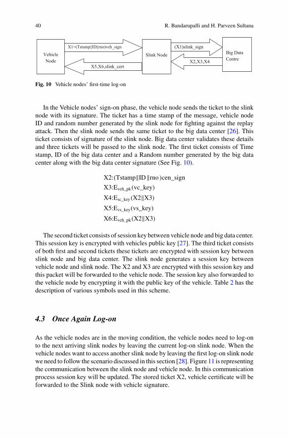
40 R. Bandarupalli and H. Parveen Sultana
VehicleNode
Slink Node Big Data Centre
X1=(Tstamp||ID||rno)veh_sign (X1)slink_sign
X2,X3,X4X5,X6,slink_cert
Fig. 10 Vehicle nodes’ first-time log-on
In the Vehicle nodes’ sign-on phase, the vehicle node sends the ticket to the slinknode with its signature. The ticket has a time stamp of the message, vehicle nodeID and random number generated by the slink node for fighting against the replayattack. Then the slink node sends the same ticket to the big data center [26]. Thisticket consists of signature of the slink node. Big data center validates these detailsand three tickets will be passed to the slink node. The first ticket consists of Timestamp, ID of the big data center and a Random number generated by the big datacenter along with the big data center signature (See Fig. 10).
X2:(Tstamp‖ID‖rno )cen_signX3:Eveh_pk(vc_key)
X4:Esc_key(X2‖X3)X5:Evs_key(vs_key)
X6:Eveh_pk(X2‖X3)
The second ticket consists of session key between vehicle node and big data center.This session key is encrypted with vehicles public key [27]. The third ticket consistsof both first and second tickets these tickets are encrypted with session key betweenslink node and big data center. The slink node generates a session key betweenvehicle node and slink node. The X2 and X3 are encrypted with this session key andthis packet will be forwarded to the vehicle node. The session key also forwarded tothe vehicle node by encrypting it with the public key of the vehicle. Table 2 has thedescription of various symbols used in this scheme.
4.3 Once Again Log-on
As the vehicle nodes are in the moving condition, the vehicle nodes need to log-onto the next arriving slink nodes by leaving the current log-on slink node. When thevehicle nodes want to access another slink node by leaving the first log-on slink nodewe need to follow the scenario discussed in this section [28]. Figure 11 is representingthe communication between the slink node and vehicle node. In this communicationprocess session key will be updated. The stored ticket X2, vehicle certificate will beforwarded to the Slink node with vehicle signature.

Security of Big Data in Internet of Things 41
Table 2 Symbols notations of vehicle node
Symbol Description
Tstamp Time stamp
Rno Random number for fighting against replay attack
Veh_sign Vehicle nodes signature
Slink_sign Slink nodes signature
Cen_sign Big data centers signature
Veh_pk Vehicle nodes public key
Vc_key Session key between big data center and vehicle node
Sc_key Session key between big data center and slink node
Vs_key Session key between slink node and vehicle node
Veh_pk Vehicle nodes public key
VehicleNode
SlinkNode
(X2,(Tstamp||veh_cert)veh_sign
Slink_Cert,Eveh_pk(vs_key)
Fig. 11 Later log-on of vehicle node
The ticket X2 consists of the big data center signature. This signature shows thatthe ticket is issued by the big data center. After that, the session key (vs_key) ofthe slink node will be encrypted with the vehicle nodes public key. This session key(vs_key) will be forwarded along with the slink node certificate (Slink_cert).
4.4 Collecting Data Securely
In the previous scenarios the secure connection will be established between theVehicle node, Slink node and big data centers. The data will be divided into twocategories, business data, and confidential data. The business data will be exchangedin the plain text format and confidential data will be exchanged securely [29]. Thebusiness data consists of the information like temperature. The X4 can be calculatedby concatenating vehicle nodes’ Id with business message M1. The hash value ofM4 is utilized for calculating HMAC. HMAC helps in stop the tampering of data.So that, the data will be sent to the receiver without any loss. The same scheme willbe used to transfer the data from a big data center to the Vehicle node. Here M2 isthe business message to be sent from the big data center to the vehicle node (SeeFig. 12).
But the confidential data need to be exchanged securely. So herewe are encryptingthe confidential data and converting into the cipher text format. Here a random key,Z is utilized for encrypting. For sharing the random key Z with the slink node andbig data center, vc_key and vs_key will be used (See Fig. 13).

42 R. Bandarupalli and H. Parveen Sultana
x4, HMAC (vc_key, H(x4))
X5=ID||M2 HMAC (vc_key,H(x5)) HMAC (sc_key,H(x5))
VehicleNode
SlinkNode
BigData
Centre
x4=ID||M1, x4, HMAC (vc_key, H(x4))
HMAC (vs_key, H(x4))
X5,HMAC(vc_key,H(x5)
Fig. 12 Exchanging of business messages for big data collection
X5=ID||M2 Evc_key(Z),Evs_key(Z),Ez(x5),
HMAC(vc_key,H(x5)),HMAC(sc_key,H(x5))
BigData
Centre
Evc_key (Z),EZ(x4), HMAC(vc_key ,H(x4))
VehicleNode
SlinkNode
x4=ID||M1, Evc_key (Z), Evs_key (Z), Ez(x4),
HMAC (vc_key, H(x4)), HMAC(vs_key, H(x4))
Evc_key(Z),Ez(x5),HMAC(vc_key,H(x5))
Fig. 13 Exchanging of Confidential messages for big data collection
4.5 Data Storage Security
In the previous sections we have discussed the secure connection establishment andsecure data collection [30]. This section describes the storing of important data inbig data center securely. All the information related to the vehicle need not be storedin the big data center. Some important information needs to be stored in the big datacenter securely [31]. Table 3 is the data structure of the information need to be storedin the big data center. It has the data structures related to both slink node and vehiclenode. The first field of the data structure is ID, the second field is the certificate. ThisID and certificate fields are used for identification purpose. The third field is statuefield. This field consists of two values “on” and “off”. If any abnormal situationoccurs, the status field will change from on to off. The next field is the time stampperiod field. If the time stamp period expires the vehicle node and slink nodes needto register once again as the new nodes. The session key and public key are importantin providing confidentiality to the data.
The business information will be stored as a plain text in the big data center [32].While storing the confidential information, the data need to be encrypted with the
Table 3 Data structure of big data center for storing slink node and vehicle node data
Nodes ID Certificate Statue Validity period Encrypted session key
Slink node Slink_ID Slink_cert Off/on Period_TStamp Sc_key
Vehicle node Veh_ID Veh_cert Off/on Period_Tstamp Vc_key

Security of Big Data in Internet of Things 43
Vehicle Nodes
Vc_key
Vc_key Big Data Centre (File name, block ID)
(Block location, \ block ID)
Instruction to State of the data node Data Node
Big Data Application
ClientJVM
Block Data (Byte Range, Block Id)
HDFSClient
Distributed file System
FSData output stream
Name Node
Data Node Data Node
Fig. 14 Distributed storage system for big data collection
session key between vehicle node and big data center (vc_key). When the vehiclenode itself interactswith the big data center, the datawill be retrieved [33].Otherwise,the data cannot be retrieved from the big data center. When the vehicle node interactswith the big data center the data will be decrypted with the session key betweenvehicle node and big data center (See Fig. 14).
As the no of vehicles is increasing day to day, the data collected from the vehiclesalso increasing rapidly. The Hadoop Distributed File System (HDFS) is a famoussystem for storing the big data. In this HDFS system we will have one name nodeand remaining all are data nodes. In the HDFS system the data will be replicatedto more than one location to avoid the fault tolerance. Whenever a vehicle nodewants to access the data, the vehicle node interacts with the big data center, theclient JVM request for the file name and block ID through the distributed file system[34]. This distributed file system interacts with the Name node. The name nodewill acknowledge the block location and block id to the distributed file system [35].Finally, FS Data output stream sends the Block ID and byte range to the data node toacquire the data [36]. If the acquired data is business data then the data will be sentto the vehicle node as a plain text. Otherwise, the data will be sent as the cipher text.The cipher text needs to be decrypted by using the session key between the vehiclenode and big data center (vc_key).
44 R. Bandarupalli and H. Parveen Sultana
5 Providing Security to Big Sensing Data Streams UsingDynamic Prime Number Based Security Verification
Real time data processing schemes require in many applications such as social net-working applications like Facebook and Twitter, large scale sensors, web exploring,financial data and surveillance data analysis [37]. Stream processing engines areintroduced with an aim to process the sensing data streams with the small delay.These engines are used to process the data in real time rather than processing afterstoring the data. But these engines are not suitable for processing the big streamdata [38]. These large quantities of data contain various data, i.e. both structured andunstructured data. As these big data streams are continuous in nature, this data needsto be processed in real time [39]. The velocity and volume of this data are huge, wecannot store this data. So, the conventional computing models are not suitable.
5.1 Security Verification of Data Streams
The big sensing data streams are used in some critical applications such as military,these data need to be secured. The sensors are having the low processing power, lesspower, low storage and also very less energy [40]. These data streams need to beprocessed during the transmission phase itself. Here providing the security to the datais a very important aspect. For providing security to the data cryptographic modelis used. There are two cryptographic models such as Asymmetric and Symmetric[41]. The asymmetric algorithms are much slower when compared to the symmetriccryptographic algorithms. But these symmetric cryptographic algorithms are failedin many cases when providing the security to the streamed data.
As the symmetric key cryptographic algorithms are failed in many cases of bigdata streaming, the dynamic prime number based security verification scheme willaddress those challenges. In this scheme, the key will be generated with the help ofprime numbers synchronously. This key is generated at regular intervals of the time[42]. This prime number generation will be done at both sensing device side as wellas at data stream manager side. As the key is generated at both source and DSMsides, it reduces communication overhead [43]. Here the key is of 64-bit size. Thissmaller key helps in faster processing of the streamed data by not compromising thesecurity. The key is updated dynamically at both source and DSM side.
5.2 Architecture of Secure Data Stream
a. Data Stream Processing
The data stream processing is a revolutionary area. Many applications are usingthis data stream processing. In data stream processing huge amounts of data need to

Security of Big Data in Internet of Things 45
Cloud for storing the
data
Buffer
Security Check
Sensing source
Sensor Networks
HealthApplications
Military Applications
Data transmission through network
Buffer
Query Processing
Data Stream Manager used for processing and security check using DPBV, MAC checking, sequence of data
checking
ProcessedData
Fig. 15 Architecture of data stream
analyze with a small delay. In conventional mechanisms data is analyzed after storingit [44]. Here the data will be generated from various sources. It is very difficult tohandle the data generated from various sources at a time [45]. And also in DSM, thedata blocks need to go under the security verification.
The Fig. 15 is representing the architecture of secure data stream. In this archi-tecture, the data stream flows from various sensor devices to the cloud. Here thearchitecture mainly focuses on three aspects, collecting the data, processing the dataand storing the data. The security and query related processes are done in DSM (datastream manager). In this architecture first of all security verification will be doneafter that query processing will be done [46]. Small buffers will be maintained forboth activities. In the final stage the data that is processed will be stored in the cloud[47]. Here the queries used for processing the data are continuous in nature, as thedata is flowing continuously.
5.3 Purpose of Symmetric Key Cryptography
The size of symmetric keys ismuch smaller in sizewhen comparedwith the asymmet-ric keys, so they require less computation power. A 128-bit symmetric key providesthe equal strength compared with the 3248-bit asymmetric key. The main aim of bigsensing data streams is to provide security to the data streams in real time. So, thesymmetric key cryptography is the best choice in this scenario. The symmetric keycryptography is 1000 times faster than other public key cryptographic algorithms. Asthe size of the symmetric key cryptography is much smaller, the attacker can easilyattack the data which is encrypted with symmetric key cryptography. To overcomethis disadvantage, the keys are generated synchronously with dynamic number basedalgorithm [48]. Here the keys will be generated at both sensing devices end as wellas at Data StreamManager at regular intervals of time. The Fig. 16 will demonstrateabout this key generation scheme.

46 R. Bandarupalli and H. Parveen Sultana
SensingDevices
Prime Number
Generation
Prime Number
Generation
DataStream
Manager
Equal Time Interval
Fig. 16 Relative dynamic prime number generation
5.4 Setup of DPBSV System
Here the system is completely untrusted. The Data stream Manager (DSM) shouldmaintain the entire sensor ID’s and also secret keys (See Table 4 and Fig. 17).
Here in this process, first of all, sensors ID and a pseudo random number willbe sent to the DSM. The DSM receives these details from Sensor. After that, theDSM retrieves secret key (keys), with the help of Retrieve key function. After that,the session key (keysi) will be generated with the help of random key function. Thissession key will be combined with the secret key. This combination will generate akey (Keyenc) used for authentication purpose. The generated key and session key willbe encrypted with the shared key (key). The hash value 1(H) will be computed withthe help of hash function. The computed hash value and sensors private key will bepassed to the sensor. The below given are the steps for computing hash value1.
Table 4 Symbols notations and descriptions
Symbol Description
SID Sensor’s ID
Rno Pseudo random number
Keyenc Key generated for authentication
H/H′/H′′ Computed hash value
Enc() Function used for encryption
Key Shared key initially used for authentication of DSM and sensor
Keyd DSM secret key
It Prime number generation interval time
RP Prime number generated randomly
PF(RP) Function used for generating the prime number randomly
Keysh DSM and sensor computed secret key
Keys Secret key of the sensor
M/M′ User authentication key which is encrypted with sensors’ secret key

Security of Big Data in Internet of Things 47
Hash Value Calculation2
DSM
Hash Value Calculation1
Hash Value Calculation3
SID, rno
H, Keyenc
H’
H’’
Enckey(Keyd, it,RP,PF(RP),Keysh,KG)
SourceSensingDevice
Authentication Fails
Fig. 17 Secure authentication procedure between DSM and source sensing device
Keys <- Retrieve (SID),
Keysi <- random (),
Keyenc <- Keys ⊕ Keysi
M � Enckey(Keysi,Keyenc
)
H � Hash(Keyenc‖M‖rno)
(1)
After that, the sensor will get the hash value (H) and key used for authenticationpurpose (keyenc). TheDSMwill get these details and finds its own secret key based onthe authentication key. The sensors secret key and authentication key (Keyenc) will beencrypted for users’ authentication. The hash value will get with the equation Hash(Keyenc||M′||rno). And validates whether the hash value generated by it and the hashvalue generated by DSM are equal or not. If M�M′ and the hash values are equal,then the authentication of DSM is successful by the sensor. If the authenticationprocess is failed then again the process will begin from step 1.
keysi = Keyenc ⊕ Keys
M′ = Enckey(keysi, keyenc
)
Hash(keyenc‖M′‖rno)
M = M′, for authentication of DSM
H′ = Hash(1‖Keyenc‖M′‖rno)
(2)
After that the H′ will be forwarded to the DSM, the DSM compares the receivedvalue with the Hash(1||Keyenc||M||rno), If these two are equal then the sensor isauthenticated successfully. If the authentication is failed then the protocol will be

48 R. Bandarupalli and H. Parveen Sultana
terminated. In this way, both the sensor and DSM authenticate each other. Aftersuccessful validation, the DSM sends another hash value to fulfill the protocol. Thehash value H′′ will be calculated as shown below.
H′′ = Hash(2‖Keyenc‖M‖rno)
5.5 Handshaking of DPBSV
During the calculation of prime numbers, we need to take care of communicationoverhead. The communication overhead must be reduced. The PF(RP) function usedto generate the prime numbers randomly at both sides. These prime numbers haveto be generated at regular intervals of the time. The DSM transmits the algorithmsrelated to generating of the prime number and keys like (Keyd,it,RP,PF(RP),KeyGen,Keysh) to each and every individual sensor by encrypting them with the shared keygenerated initially. This transferred information will be stored in the trusted part ofthe sensor.
After successful completion of handshaking process, the data needs to betransmitted securely. This secure transmission and verification can be done by usingseveral functions and keys. As discussed earlier this scheme utilizes dynamic primenumber generation process. This dynamic prime number generation can be done atboth sensor and DSM side. Each and every sensor will have its own key. Initiallyshared key and prime numbers will be generated by the DSM itself. Next primenumber will be generated depending upon the current prime number and the intervaltime. The shared key will be generated by the sensors depending upon the formulaKeysh � Hash(Enc(RP,keyd)). Here, each and every data block consists of two parts.The first part consists of the encrypted data. This data will be encrypted with thehelp of secret key Keyi and shared key keysh. These three things will be mutuallyexclusively ORED. DATA ⊕ Keyi ⊕ keysh. This encryption is mainly used forintegrity checking. The second part is used for authentication checking. Si ⊕ keysh.So finally the resultant block is
(DATA ⊕ Keyi ⊕ keysh)‖( Si ⊕ keysh.)
Lets Id = DATA ⊕ Keyi ⊕ keyshAd = Si ⊕ keysh
In the next step the sensor will send the encrypted format of the above data block
Enck(Ad‖Id)

Security of Big Data in Internet of Things 49
5.6 Security Verification of DPBSV
The security verification should be done in real time. The main aim of the securityverification is to provide the end to end security. This security verification will bedone at DSM side. In the security verification the DSM verifies whether the datais modified or not. And also it verifies whether the data is from the authenticatednode or not. First of all the DSM will decrypt the data block to check the integrityand authenticity. First of all the DSM authenticates each and every block. And theintegrity will be checked at the arbitrary interval blocks. The interval may vary from0 to 6. i.e. the interval blocks may be 6 at most or 0 at least.
The Fig. 18 representing the updating of shared and also the security verificationof the data. The updating of the shared key will be done at both sources sensingdevice side as well as at Data stream manager side. But the security verification willbe done only at DSM side.
SID=AD ⊕ Keysh
DATA=ID⊕Keysh⊕ Keyi
SourceSensingDevice
Data stream Manager
PF(RP) IntervalTime-It
Keysh=Hash(Enc(Pi,
Keyd))
Hash (Id||Ad)
Keysh=Hash(Enc(Pi,Keyd))
Id=DATA ⊕Keysh⊕Keyi
Ad=Si⊕Keysh
Fig. 18 Updating of shared key and verification of security

50 R. Bandarupalli and H. Parveen Sultana
6 Conclusion
In this chapter, we discussed two security algorithms. The first algorithm is used toprovide the security to the vehicular data. In this methodology, the vehicular nodesand slink nodes need to register at big data center. In this methodology, single sign-onalgorithmwas used for login to the big data center. Symmetric key cryptography wasused in this methodology. The second algorithm is for providing the security to theSensor data. Here the dynamic prime number based security scheme was used forproving security to the big data. This prime number generation will be done at bothsources as well as at big data center side.
References
1. Guo L, Dong M, Ota K, Li Q, Ye T, Wu J, Li J (2016) A secure mechanism for big datacollection in large scale internet of vehicle. IEEE Internet Things J, https://doi.org/10.1109/jiot.2017.2686451
2. Guerrero-ibanez JA, Zeadally S, Castillo JC (2015) Integration challenges of intelligent trans-portation systemswith connected vehicle, cloud computing, and internet of things technologies.IEEE Wirel Commun 22(6):122–128
3. Puthal D, Nepal S, Ranjan R, Chen J (2017) A dynamic prime number based efficient securitymechanism for big sensing data streams. J Comput Syst Sci, Science Direct 22–42
4. Walravens C, DehaeneW (2012) Design of a low-energy data processing architecture forWSNnodes. In: Proceedings of the conference on design, automation and test in Europe,March 2012,pp 570–573
5. Walravens C, Dehaene W (2014) Low-power digital signal processor architecture for wirelesssensor nodes. IEEE Trans Very Large Scale Integr (VLSI) Syst 22(2):313–321
6. Kaddoura I, Abdul-Nabi S (2012) On formula to compute primes and the nth prime. ApplMathSci 6(76):3751–3757
7. Perrig A, Szewczyk R, Tygar J, Wen V, Culler DE (2001) SPINS: security protocols for sensornetworks. In: Proceedings of ACM MobiCom’01, 2001, pp 189–199
8. Akyildiz I, SuW, SankarasubramaniamY, Cayirci E (2002)Wireless sensor networks: a survey.Comput Netw 38(4):393–422
9. Hempstead M, Lyons MJ, Brooks D, Wei G (2008) Survey of hardware systems for wirelesssensor networks. J Low Power Electron 4(1):11–20
10. Burke J, McDonald J, Austin T (2000) Architectural support for fast symmetric-key cryptog-raphy. ACM SIGOPS Oper Syst Rev 34(5):178–189
11. Puthal D (2012) Secure data collection and critical data transmission technique in mobile sinkwireless sensor networks. M. Tech thesis, National Institute of Technology, Rourkela
12. TCG Trusted Platform Module (TPM) specification, https://www.trustedcomputinggroup.org/specs/tpm/. Accessed on 04 Aug 2014
13. Nepal S, Zic J, Liu D, Jang J (2011) A mobile and portable trusted computing platform.EURASIP J Wirel Commun Netw 2011(1):1–19
14. Gulisano V, Jimenez-Peris R, Patino-Martinez M, Soriente C, Valduriez P (2012) Streamcloud: an elastic and scalable data streaming system. IEEE Trans Parallel Distrib Syst23(12):2351–2365
15. Guo L, Wu J, Xia Z, Li J (2015) Proposed security mechanism for XMPP-based communica-tions of ISO/IEC/IEEE 21451 sensor networks. IEEE Sens J 15(5):2577–2586
16. AalmKM, Saini M, Saddik AE (2015) Toward social internet of vehicles concept, architecture,and applications. IEEE Access 3:343–357

Security of Big Data in Internet of Things 51
17. Cecchinel C, Jimenez M, Mosser S, Riveill M (2014) An architecture to support the collectionof big data in the internet of things. In: Proceedings of the IEEE 10th World Congress onservices, Anchorage, June 2014, pp 442–449
18. Su Z, Xu Q, Qi Q (2016) Big data in mobile social networks: a QoE-oriented framework. IEEENetw 30(1):52–57
19. Guo L, DongM,Ota K, JunW, Li J (2015) Event-oriented dynamic security service for demandresponse in smart grid employing mobile networks. China Commun 12(12):63–75
20. Tracey D, Sreenan C (2013) A holistic architecture for the internet of things, sensing servicesand big data. In: Proceedings of the 13th IEEE/ACM international symposiumon cluster, cloud,and grid computing, Delft, May 2013, pp 546–553
21. SalahuddinMA,Al-FuqahaA,GuizaniM (2015) Software-defined networking for RSU cloudsin support of the internet of vehicles. IEEE Internet Things J 2(2):133–144
22. Li H, Lu R, Zhou L, Yang B, (Sherman) Shen X (2014) An efficient Merkle tree based authen-tication scheme for smart grid. IEEE Syst J 8(2):655–663
23. Li H, Lin X, Yang H, Liang X, Lu R, (Sherman) Shen X (2014) EPPDR: an efficient privacy-preserving demand response scheme with adaptive key evolution in smart grid. IEEE TransDependable Secure Comput 25(8):2053–2064
24. Li H, Yang Y, Luan TH, Liang X, Zhou L, (Sherman) Shen X (2015) Enabling fine-grainedmulti-keyword search supporting classified sub-dictionaries over encrypted cloud data. IEEETrans Dependable Secure Comput
25. Liu C, Zhang X, Liu Z, Yang Y, Ranjan R, Georgakopoulos D, Chen J (2013) An iterativehierarchical key exchange scheme for secure scheduling of big data applications in cloudcomputing. In: Proceedings of the 12th IEEE international conference on trust, security andprivacy in computing and communications, Melbourne, July 2013, pp 10–16
26. Adluru P, Datla SS, Zhang X (2015) Hadoop eco system for big data security and privacy. InProceedings of the 2015 IEEE Long Island Systems, Applications and Technology Conference(LISAT), Farmingdale, May 2015, pp 1–6
27. Jam MR, Khanli LM, Akbari MK, Javan MS (2014) A survey on security of Hadoop. In:Proceedings of the 4th International Conference on Computer and Knowledge Engineering(ICCKE), Mashhad, Oct 2014, pp 716–721
28. Xu L, Jiang C, Wang J, Yuan J, Ren Y (2014) Information security in big data privacy and datamining. IEEE Access 2:1149–1176
29. Wang H, Qin B, Wu Q, Xu L, Ferrer JD (2015) TPP: traceable privacy-preserving communica-tion and precise reward for vehicle-to-grid networks in smart grids. IEEE Trans Inf ForensicsSecur 10(11):2340–2351
30. Soares J, Borges N, Canizes B, Vale Z (2015) Probabilistic estimation of the state of electricvehicles for smart grid applications in big data context. In: 2015 IEEE Power & Energy SocietyGeneral Meeting, Denver, July 2015, pp 1–5
31. Mershad K, Artail H (2013) A framework for secure and efficient data acquisition in vehicularad hoc networks. IEEE Trans Veh Technol 62(2):536–551
32. Gulisano V, Jimenez-Peris R, Patino-Martinez M, Valduriez P (2010) Streamcloud: a largescale data streaming system. In: Proceedings of 30th International Conference on DistributedComputing Systems, ICDCS, 2010, pp 126–137
33. Arasu A, Babcock B, Babu S, Datar M, Ito K, Nishizawa I, Rosenstein J, Widom J (2003)STREAM: the stanford stream data manager (demonstration description). In: Proceedings ofthe 2003 ACM SIGMOD International Conference on Management of Data, 2003, p 665
34. Carney D, Çetintemel U, Cherniack M, Convey C, Lee S, Seidman G, Stonebraker M, TatbulN, Zdonik S (2002) Monitoring streams: a new class of data management applications. In:Proceedings of the international conference on very large data bases, 2002, pp 215–226
35. Abadi DJ, Carney D, Çetintemel U, Cherniack M, Convey C, Lee S, Stonebraker M, Tatbul N,Zdonik S (2003) Aurora: a new model and architecture for data stream management. VLDB J12(2):120–139
36. Chandrasekaran S, Cooper O, Deshpande A, Franklin M, Hellerstein JM, Hong W, Krishna-murthyS,MaddenSR,Reiss F, ShahMA(2003)TelegraphCQ: continuous dataflowprocessing.

52 R. Bandarupalli and H. Parveen Sultana
In: Proceedings of ACM SIGMOD International Conference on Management of Data, 2003,p 668
37. Tatbul N, Çetintemel U, Zdonik SB (2007) Staying fit: efficient load shedding techniques fordistributed stream processing. In: Proceedings of international conference on Very Large DataBases, VLDB, 2007, pp 159–170
38. Jin M, Zhou X, Luo E, Qing X (2015) Industrial-QoS-oriented remote wireless commu-nication protocol for the internet of construction vehicles. IEEE Trans Industr Electron62(11):7103–7113
39. Puthal D, Sahoo B (2012) Secure data collection & critical data transmission in mobile sinkWSN. In: Secure and energy efficient data collection technique. LAPLambert Academic Pubil-ishing, Germany, ISBN978-3-659-16846-8
40. Kumar N, Rodriguesand JJPC, Chilamkurti N (2014) Bayesian coalition game as-a-service forcontent distribution in internet of vehicles. IEEE Internet Things J 1(6):554–555
41. Fu J, Chen Z, Sun R, Yang B (2014) Reservation based optimal parking lot recommendationmodel in internet of vehicle environment. China Commun 11(6):38–48
42. Cheng J, Cheng J, ZhouM, Liu F, Gao S, Liu C (2015) Routing in internet of vehicles a review.IEEE Trans Intell Transp Syst 16(5):2339–2351
43. Dua A, Kumar N, Bawa S (2014) A systematic review on routing protocols for vehicular adhoc networks. Veh Commun 1(1):33–52
44. Li B, Zhao C, Zhang H, Sun X (2013) Characterization on clustered propagations of UWBsensors in vehicle cabin:measurement,modeling and evaluation. IEEESens J 13(4):1288–1300
45. Kumar N, Misra S, Rodrigues J, Obaidat MS (2015) Coalition games for spatio-temporalbig data in internet of vehicles environment: a comparative analysis. IEEE Internet Things J2(4):310–320
46. Zhou Y, Chen S, Zhou Y, Chen M (2015) Privacy-preserving multi-point traffic volumemeasurement through vehicle-to-infrastructure communications. IEEE Trans Veh Technol64(12):5619–5630
47. Wu Q, Ferrer JD, Nicolas ÚG (2010) Balanced trustworthiness, safety, and privacy in vehicle-to-vehicle communications. IEEE Trans Veh Technol 59(2):559–573
48. Li H, Liu D, Dai Y, Luan TH (2015) Engineering searchable encryption of mobile cloudnetworks: when QoE meets QoP. IEEE Wirel Commun 22(4):74–80
49. Cárdenas AA, Manadhata PK, Rajan SP (2013) Big data analytics for security. IEEE SecurPriv 11(6):74–76

IoT for Ubiquitous LearningApplications: Current Trendsand Future Prospects
Salsabeel Shapsough and Imran A. Zualkernan
Abstract Concept of ubiquitous learning is not new, and over the years, ubiquitouslearning applications have migrated from the web to mobile-based applications withan increased use of onboard sensors. The current surge in Internet of Things (IoT)has the potential to enable another shift towards a new class of ubiquitous learningapplications that rely on cheap sensors, edge devices, and IoT middleware and pro-tocols to enact unique and innovative ubiquitous learning designs. This chapter willfirst present a survey of key ubiquitous learning applications that use sensors andedge devices in a meaningful manner, showing that such applications are typicallyconstructed in an ad hoc manner, and mostly use web-based protocols like the HTTP.After the survey, this chapter will present a typology of current ubiquitous learningapplications and map this typology to the various components of the IoT stack. Rep-resentative ubiquitous learning systems in the areas of language and social scienceslearning, science and technology learning, and domain independent learning will beconsidered. Thirdly, based on recent trends in IoT technologies, new architecturesand future, prospects for IoT-based ubiquitous learning applications will be explored.
1 Introduction
Ubiquitous Learning is defined in literature as learning anything, anywhere, any-time. A ubiquitous learning application is designed to eliminate the constrictionsof a typical classrooms by presenting customizable learning content over platformsfamiliar to learners [1]. The recent advancements in internet computing technolo-gies, however, have morphed the term into a wide umbrella under which fall variousapplications that incorporate sensing and communication technologies for a situ-ated, context-aware learning environment [2]. Using interactive elements such asRFID tags, QR-codes, and smart sensors, learning can take place outside classrooms
S. Shapsough (B) · I. A. ZualkernanDepartment of Computer Science and Engineering, American University of Sharjah, Sharjah,United Arab Emiratese-mail: [email protected]
© Springer Nature Switzerland AG 2019N. Jeyanthi et al. (eds.), Ubiquitous Computing and Computing Security of IoT,Studies in Big Data 47, https://doi.org/10.1007/978-3-030-01566-4_3
53

54 S. Shapsough and I. A. Zualkernan
and in authentic settings. Over the years, dozens of environments and mobile appli-cations have been developed to implement the concept of ubiquity in learning. In[3], Njoku analyzes 135 studies on ubiquitous learning environments conducted inthe year 2015-106, retrieved from the seven top journals on education and learningtechnologies. Among the main research questions were: “which subjects do ubiqui-tous learning studies focus on the most?” and “at which academic level are studiesmore likely to participate in these studies?” Analyzing the 135 articles showed thatmost studies are aimed at undergraduate students enrolled in science courses, whilethe least considered subjects were law and mathematics, and the least common testgroup was postgraduate students. Furthermore, the analysis found a 100% increasein the number of publications ubiquitous learning studies and environments per year,compared to the number between the years 2010 and 2013 [4] which, at the time,suggested a steadily-growing interest in the field over the past decade. Most of thosesystems allow communication with Learning Management Systems, providing anopportunity to scale such systems to incorporate learners from different schools.
2 Previous Work on Ubiquitous Learning Applications
Ubiquitous learning environments depend mainly and heavily on two types of tech-nologies: asset tracking and sensing technologies to facilitate context incorporation,and user applications. This led to such environments evolving to reflect the mostrecent trends in both fields.
2.1 Early Attempts at Ubiquitous Learning Environments
Ubiquitous technologies have repeatedly been used to aid students learning lan-guages, history, and science by creating interactive environments. Such environmentsplace learners in situations where they either interact with ubiquitous technologies toaccess information, or use their knowledge to engage in activities and complete tasksthat involve using ubiquitous technologies. Early ubiquitous platformswere designedmostly for language and culture studies. The platformswere designedmainly for PDAusers, and employed features such as cameras, microphones, and wireless commu-nication. Language platforms presented learners with tasks that require using newvocabulary to identify locations and objects, and correct grammar to communicatewith locals andpeers [5–7]. Saito et al. presents a studyonbasic support for ubiquitouslearning (BSUL) environments; light weight and simplicity, adaptiveness and cus-tomization, support for various learning styles, and support for collaborative learning[5]. Such systems have often been implemented using internet-connected PDAs andpersonal computers in coordinance with existing Learning Management Systems(LMS); thus, allowing students to seamlessly learning experience where they haveaccess to any information they need, whenever they need it. To conduct the study,

IoT for Ubiquitous Learning Applications: Current Trends … 55
a ubiquitous learning software was developed implementing the activities seen asmost important in classrooms; including: report submission and attendance taking,in addition to student feedback and assessment response. The system was used inmultiple case studies, most notably a Language-learning outside the classroom withhandhelds (LOCH) case study [6] where students enrolled in a Japanese languagecourse were asked to walk around town and perform certain tasks, aided by theirPDAs. For example, students were asked to engage in conversations with locals toacquire certain information such as prices of different products and different out-lets’ opening hours. Another type of tasks required them to conduct interviews withschool faculty in Japanese, and use their PDA to take a photo of the intervieweeand note down important information. The PDAs were connected to the internet;meaning that the instructor will be able to track students on a map and update themwith new tasks and/or feedback. Chen et al. introduces a personalized context-awareubiquitous learning system (PCULS) that helps students learn English by focusingon vocabulary [7]. By taking the learner’s vocabulary level, learning time, and theirlocation—acquired using wireless network positioning—the environment is able toadapt and customize the content in order to provide a better learning experience.
In culture study courses, learners on a fieldtrip can learn about the history and cul-ture of a location by completing tasks that required them to walk to certain locationsand answer questions related to the history of said location. Museums, for example,often resort to electronic trails in order to provide guests with an educational expe-rience [8]. A museum trail is typically a paper, brochure, or pamphlet that guidesguests through different sections, providing brief historical facts about each object.Electronic trails provide the same information but in different forms, including audioand video. Electronic trails also allow museum visitors to add feedback and reflec-tions in the different forms. This is particularly useful for visitors who wish to accessthe information later on; to prepare a presentation about their visit, for example. In[9], students from 10 primary schools learning about the history of Amsterdam wereasked to walk around the city, observing various monuments and learning about his-torical characters and stories hidden within their walls. Each group of students wasdivided into a city team (CT) and a headquarter team (HQT). The CT students willthen walk around the city and use UMTS/GPS phones to perform certain tasks andshare new findings with the HQT students, while HQT students provided directionsusing a modern map and a medieval map of the city; with the end goal being a fullnarrative that connects various historical elements of the city. The project buildson the concept of “storification”, where students are more likely to understand andremember historical characters and events when they are woven into a narrative.Being in the same vicinity as said elements adds a dimension of reality, helpingstudents draw a full picture of events that took place around the city. Learners usingthese platforms to request, contribute, and exchange text, audio, and video-basedinformation that aid them in completing different tasks. Location services such asGPS and WiFi localization were often used to either customize learning material, orconfirm a learner has completed a certain task by arriving at a particular location. Theplatforms also often made use of wireless communication and messaging protocolsto facilitate peer-to-peer communication.

56 S. Shapsough and I. A. Zualkernan
2.2 The Introduction of Passive Sensors to UbiquitousLearning
With subjects like natural science and engineering courses, on the other hand, thefocus is on the learners’ ability to identify and interact with physical objects. Beforethe incorporation of technologies such as QR codes and barcodes, physical objectsserved as “observables”. The learners’ inputs about them in the form of remarksand questions gave the objects presence in the system. The availability of QR-codes,barcodes, and RFID tags at a low cost changed that by giving physical objects andlocations a real presence in the virtual system. Learning material and tasks could betied to certain locations and objects using code, and learners can interact with themby scanning them [10–15].
The authors in [10] present the results of a study that investigates the effect ofcontext-aware ubiquitous learning environments on theperformanceofEnglish learn-ers. In the study, students are divided into two groups; a control group, and an exper-imental group. Both groups were asked to perform 3 activities: practice listening andspeaking during their free time, participate in activities during class time, and per-form a story relay. The control group was provided with classical learning aid suchas printed materials, audio CDs, and voice recorders. The experimental group, onthe other hand, was provided with HELLO (Handheld English Language LearningOrganization); an application that runs on their mobile phones and presents each ofthe tasks in the form of a game that they can play outdoors. Context-awareness isimplemented using area-specific QR codes; which students use their phones to scanand download different learning material depending on their location. The authorsof [11] present the design and evaluation of a u-learning application designed to easethe process of editing ubiquitous learningmaterial. In their work, Chin et al. present asystem that consists mainly of a mobile application and a main server. Students walkaround an area where certain elements have been labeled with QR-codes. A studentcan scan a QR-code and download learning content that has been previously editedand uploaded by their teacher. Students are then asked to use this information toperform different tasks. The system was used in a study where first year college stu-dents learnt about the Taiwanese Cultural Heritage; in which QR-code were placedon different artifacts such as statues and old journals. Not only did students report ahigher level of enjoyment compared to typical learning methods, but they were ableto achieve higher scores. Similarly, [12] presents a game that combines the use of QRcode with the concept of prompt-based learning. In this game, students studying 5thgrade-level natural science are assigned unique locations in a garden which serves asa home for different kinds of plants. Students move around the garden based on rollsof dice, and earn points by completing tasks where they are asked to locate a certainplant and answer questions about its characteristics using material they download byscanning QR codes. Scanning the QR also serves as a way to locate the student andidentify their context, which is then used to form the next task. Hung et al. describesa similar system in [13] under the title Context-aware Reflection Prompt System(CRPS), with the main difference being the prompt and response type. This is moti-

IoT for Ubiquitous Learning Applications: Current Trends … 57
vated by studies that claim students enjoy a better learning experience when promptsare in video format rather than text. Not only are videos believed to be more engag-ing, but they fit better into real-life narratives. Liu et al. presents an environment ofubiquitous learning with educational resources (EULER) designed to aid studentsstudy natural sciences by going to outdoor locations [14]. Students, for example, canlearn about animals by walking around a zoo and accessing context-specific learningmaterial at different zones. This is made possible by placing RFID tags at differ-ent areas and cages; where the student will use their devices to scan the RFID tagand download available information uploaded by their teacher. Groups of studentsthen combine their findings into a report to be reviewed by their teacher. Another,similar system that uses QR codes and NFC objects to teach students about hard-ware components of a computer is presented in [15]. One thing that is emphasizedin the latter but never mentioned by the previously is that many of these systemsare what is now considered the simplest form of an Internet of Things application.RFID, QR codes and NFC are the some of the easiest and most common ways toturn everyday objects into “things”. The reoccurring pattern among those systems islearners using PDAs or smartphones to scan codes, download learning content, andcommunicate with peers using HTTP or GSM over a wireless or a cellular network.In [15], Gomez et al. show how a QR code/NFC-based ubiquitous learning systemcan fit into the classical IoT paradigm; which consists of three layers: things, com-munication technologies, and clients. In this case, QR codes and NFC objects arethings, websockets over WiFi is the communication layer, and a mobile applicationallows users to interact with the system at the client level. The relation between IoTand ubiquitous learning environments was also recognized by [16, 17]. In [16] wherean IoT-based ubiquitous learning system incorporates NFC and QR technologies tooffer a Teaching by Example and Learning by Doing (TELD) experience for stu-dents studying perishable products auction. In this application, products offered forauction are tagged with QR codes and NFC tags. Students playing as either biddersor auctioneers use a mobile application to scan the objects to perform actions such asoffer an object for auction, set initial price, bid on objects, and mark objects as sold.Students can also access information related to the offered objects, as well as marketdynamics. The auction experience is carried out over a wireless network via WiFi orBluetooth. Finally, in [17] students study Logistics and Supply Chain Managementbut immersing themselves in three TELD smart environments. A learning factory,learning distribution center, and learning retail shop are made smart by equippingobjects, areas, and checkpoints with RFID tags and readings. The RFID hardwareaspect is used in addition to wireless communication and cloud computing softwaretechnologies to simulate a real-life supply chain and provide hands-on training.
This all leads to the question of “how much can IoT technologies offer to the fieldof ubiquitous learning?”

58 S. Shapsough and I. A. Zualkernan
2.3 IoT-Assisted Ubiquitous Learning
With IoT-based technologies gaining momentum the recent decade or so, cheapsensor technologies becamemore readily available than ever; and subsequently foundtheir way into u-learning. There are several examples of ubiquitous environmentswhere wearable sensors and simple microcontrollers were employed to transformthe learning experience into a game of hide-and-seek; adding an element of healthyphysical activity to academics [18, 19]. Cheap active and passive sensors can bealso be used to acquire quantitative readings such as temperature and humidity in anarea [18, 19], or provide input on the state and dimensions of an object [19]. Prete-a-apprendre [18] is a u-learning system that incorporates the concept of context-aware ubiquitous learning into primary school mathematics, but adds an elementof physical activity to it. In this system, students are asked to come up with threetrue-or-false math questions each at the beginning of the game. After the questionshave been collected, the game begins and a random question is assigned to onestudent each round. The assignment is done usingwearable, zigbee-equippedLilypadmicrocontrollers sewn into each student’s shirt. The shirt also has two pressure sensorpatches; one for “true”, and another for “false”. In each round, the shirt of the studentthat has been assigned a question lights up, and other students must try to catch themand answer the question using the pressure sensors. Hoodies and Barrels [19] isanother, similar system where children play hide and seek based on mathematicalconstrains set either by their teacher or by themselves. The system also incorporateswearable technology that is used to send children rules for the type of place wherethey can hide; e.g. behind a barrel that is 1 m2 in volume. The child has to formulatethe rules themselves and then send it to their peers; who then use that rule to find them.In terms of mathematical knowledge, while Prete-a-apprendre focuses on theory andstudents doing mathematical operations on the fly, Hoodies and Barrels is moreconcerned with students’ perception of concepts such as shapes and volumes. Thelatter trait is also often the main focus of u-learning systems developed for sciencecourses such as biology and geology. OBSY [20] is an excellent example of systemsthat implement context-aware u-learning which emphasize the students’ perceptionof and interaction with their physical surroundings. The developers make use of oldPC tablets that were distributed to schools in rural Northern Thailand as a part of theOne Tablet PC per Child policy. Each student is offered a Raspberry Pi-based sensornode equipped with a camera and a group on sensors that they can interact with viaan application deployed on their tablet. The system aims to connect students to theirenvironment by offering them the chance to associate their own experience witha space with quantitative values acquired by sensors. Using the camera, studentsare also able to monitor elements in their environment—for example, the growthof a small plant—in order to add a realistic experiential value to is usually taughtthrough textbooks. The student can move around campus, position their personalnode (OBSY) anywhere theywish, and take sensor readings and footage to be used inansweringdifferent questions.Another example of context-aware ubiquitous learningwith inquiry-based learning is Archi-Pods [21]. In this system, students enrolled in an

IoT for Ubiquitous Learning Applications: Current Trends … 59
Architecture Principles university-level course are provided with web-based mobileapplications that interact with sensor nodes distributed around campus. The nodesare equipped with various sensors including temperature, motion, and illumination.Students are asked to walk around campus, interact with sensor nodes to acquiresensor readings, and then incorporate this information into constructing or answeringinteresting questions about a particular space. In one task, for example, students areasked to locate an architectural element such as an arc. Once a student has located anarc, they can take a photo using their mobile phones and use it to answer the question.In another task, students are asked to find illumination level in a space, and relate itto how the space is being used. The system also allows students to rate questions,which in turn works as a mechanism for improving their question posing skills andelevating critical thinking.
In such systems, sensing nodes would be spread out over a particular location suchas a campus or a garden, and learners would be required to walk around the area,communicating with different nodes and completing location-unique tasks. Micro-controllers like Particle’s Photon and Electron [22], Arduino [23], and Adafruit’sFeather series [24] are used to integrate sensor readings. More sophisticated sensornodes are built using microcomputers like Raspberry Pi [25], C.H.I.P [26], Beagle-Board [27], ODROID [28], Samsung’s ARTIK series [29], and Intel’s Edison [30].In addition to sensing, microcontrollers and microcomputers provide varying levelsof networking, messaging, and application hosting. One group of researchers sug-gests using learning robots as the sensing node element [31]. Chen et al. propose thedesign of a subject-independent Ubiquitous Open-structured Neo-tech Edutainment(u-ONE) architecture which combines learning robots, sensing technology, mobilecomputing, and wireless networks [31] to support children’s learning. The frame-work is designed based on the concepts of experiential and gamified learning, andcan be used in instruction, collaborative learning, and adaptive self-learning. A totalof five hardware component types are defined in an implementation of the system:a wireless network, an output element, a mobile computing element, perception ele-ments like sensor and RFID, and a learning robot. The inclusion of all five elementsis claimed to be essential, although the choice of product for each category and howthey are integrated into the system is left to the developer. This is meant to pro-vide flexibility in terms of customization and cost; as implementation may differdepending on the subject being taught, and more importantly-on the availability andaffordability of different products. Each student is provided with one or more per-ception elements to help them interact with their surroundings, and a learning robotthat serves as their access point to the system. On the other side of the classroom,the instructor is provided with a mobile computing device capable of collecting andprocessing student performance data, and any sort of output screen to display theresults. For the most part, the framework mimics all of the systems discussed earlier;with the exception of the learning robots. In addition to adding a touch of fun into thelearning environments, they can provide real-time one-on-one interaction with everystudent and real-time feedback; thus, reducing the pressure on the instructor whowill otherwise have to divide their time, attention, and energy among all students.Three scenarios have been suggested for how the system may be used. In case of an

60 S. Shapsough and I. A. Zualkernan
instruction-based class period, instruction material will be distributed to the learn-ing robots, and students will have equal chances to participate during the lecture.The same learning robot can also be used to communicate with other students in acollaborative learning session, or provide adaptive learning material in the case ofself-learning. Wireless communication between different stations is most crucial inthe first and second scenarios, but is not needed for self-learning; as most learningmaterial is pre-downloaded into the station at the beginning of the session.
Other systems went as far as employing sensors embedded in learners’ smart-phones [32, 33], and smart technology like Google Glass [34] as the sensing ele-ment. This provided learners with access to environmental information on the go,allowing them to conduct comparisons between their personal experience and realquantitative information, and document their experience as they go. In [33], Shap-sough et al. present the design and evaluation of an assessment systemwhere studentsuse smartphones to access and answer assessments set by their teachers. The use ofsensor data in this particular system differs from other discussed systems becausethe readings are not involved in the students’ answers; but are relevant to under-standing the context in the student was while answering the assessments. However,only few application-level modifications will be needed in order to change the sys-tem so that it allows students to access the sensor information and incorporate themin their answers. WeSPOT (Working Environment with Social, Personal and OpenTechnologies for Inquiry Based Learning) [32] is another example that implementsthis category of learning systems. It is an inquiry-based learning system based onthe Personal Learning Environment (PLE) paradigm-a learner-centric environmentwhich provides tools and services for students to design their own learning experi-ence. WeSPOT aims to patch the gap between different inquiry tools and services,students’ profiles, and the curricular con-text in order to create a cohesive learningenvironment tailored to the students’ needs. The environment offers students a game-like experience that is meant to mimic the sort of interaction that takes place in socialmedia. This, the developers believe, motivates the students to take advantage of thesystem’s capabilities as they feel a sense of accomplishment earning points in formof badges as they reach certain milestones. Students can access the system throughtheir mobile application that they can download on their smartphones and proceedto pose and answer questions that fall under tasks specified by the instructor. Thesystem also supports a type of tasks where students are asked to collect visual andaudio information from their environment through their smartphones, which incor-porates the element of personal experience into the learning process. Google GlassPersonal Inquiry Manager (Glass PIM or GPIM) [35] is a Glassware (Google Glassapplication) that was introduced in order to elevate the WeSPOT experience. GPIMfocuses on the experimental aspect of the environment as students can now incorpo-rate images, audio, and video taken by their Google Glass unit into their inquiries.The incorporation of Google Glass is meant to provide smoother flow of informationbetween the students’ physical surroundings and the learning system, and makes iteasier for the student to keep track of their peers’ contributions while working tocomplete their tasks, instead of having to constantly shift their attention between theapplication and their surroundings.

IoT for Ubiquitous Learning Applications: Current Trends … 61
3 The Generic IoT Architecture
There are several published works that compared available e-learning and ubiquitouslearning platforms. In addition to the ones previously discussed in [3] and [4], thework done [36, 37] present comparisons between different platforms in literature. Inboth publications, the authors survey a number of e-learning and u-learning environ-ments, and compare them in terms of technical support, and case study dimensions.Such comparisons are useful to acquire a general picture of the technologies involvedin u-learning environments. However, in order to bring the field of u-learning into theInternet of Things (IoT) paradigm, it is more sensible to examine existing systemsin the light of said paradigm. Different authors, developers, and stakeholders presentdifferent versions of the IoT generic architecture; which often vary in the number oflayers defined and the classification of technologies into the layers. This arises fromthe fact that people from different backgrounds are taking part in the IoT revolution[38]. A corporation, for example, will define a paradigm that more based on supplychain and business operations, while a telecommunication institute will focus moreon the communication technologies and topologies. A generic architecture is derivedfrom ones proposed in [38–42]. The architecture consists of four layers: perception,network, middleware, application (Fig. 1).
The Perception Layer (PL), sometimes referred to as theDevice Layer- is providesinterfaces between the system and the physical world, mainly identifying objects andcontext, and acquiring data. Technologies that fall under this layer are sensors, QRcodes, RFID, smart meters, and others. The next layer is the Network Layer (NL),which provides communication media between PL devices and upper layers in thearchitecture. The layer covers small-scale and wide-scale networks, and employswireless communication technologies such as Wi-Fi, Bluetooth, and others. On topof the NL is the Middleware Layer (ML), which provides management services as
Fig. 1 Internet of Thingsarchitecture
62 S. Shapsough and I. A. Zualkernan
well as databases, processing services, messaging brokers, and others. The layeris responsible for handling the heterogeneity of the devices in the IoT system andproviding a seamless exchange of information. Following the ML is the ApplicationLayer (AL) which provides interfaces between the users and the IoT system in theform of mobile applications, websites, reports, and others. A comparison of thediscussed ubiquitous environments can then be conducted based on how they fit intoIoT paradigm (Table 1). Some of the systems are custom-made; the developer isgiven the responsibility of choosing the product/technology for each element, andthen integrate them together. This is highly inefficient considering that most systems,in essence, have the same requirements and are designed to achieve the same goal.A unified architecture for this class of systems will massively reduce the design andimplementation time required to produce a system instance. Other works such as[11, 31–34], on the other hand, attempt to implement said unified architecture.
4 Ubiquitous Learning Applications Mapped to the IoTArchitecture
Table 1 demonstrates the main components of each reviewed ubiquitous learningenvironment as they fit into the IoT architecture’s four layers. From analyzing thecomponents of each application, one can notice a few interesting trends. At the per-ception layer, the sensing element in earlier systems was features that were alreadyincluded in PDAs such as cameras andmicrophones.As sensing technologies becamemore commercialized, ubiquitous learning environments often adopted such tech-nologies and edge devices increased in sophistication. The same trend is also presentat the application layer, where front-end applications moved from being designed forPCs and browsers, to adopt latest technologies in mobile and cross-platform apps.At the network layer, WiFi is the most common wireless protocol, with lighter pro-tocols such as ZigBee and Bluetooth being offered as additional options in severalenvironments. At the middleware layer, while middleware and databases are oftenhinted at but not explicitly identified, it appears that Hyper Text Terminal Proto-col (HTTP) is the go-to application-level messaging protocol. Natively based on arequest-response architecture, HTTP iswell-suited for interactions between learners’devices and objects, where the learners are clients requesting resources from a localor remote server. The protocol is compatible with web applications, which were thenorm in earlier ubiquitous learning systems. Yet, it is peer-to-peer transactions suchas a learner sharing findings from a location, a learner posing a context-specific ques-tion, or assessments being assigned to specific access points are at the heart of everyubiquitous learning application. In such cases, HTTP requires additional middlewareto provide a pseudo peer-to-peer network. The backend servers also needed to imple-ment a pseudo publish/subscribe architecture in order to keep learners updated onnew contest. Where that was not the case, the dissipation of information dependedon the frequency at which learners requests an update.

IoT for Ubiquitous Learning Applications: Current Trends … 63
Table1
Ubiquito
uslearning
platform
sas
they
fitinto
theIoTarchitecture
System
Year
Perceptio
nlayer
Networklayer
Middlew
arelayer
App
lication
layer
Dataform
at
Edgedevice
Sensing
elem
ent
Messaging
Database
Middlew
are
PCULS[7]
2010
Phone
WLAN
localiz
ation
WiFi
SMS,
HTTP
SQL
N/S
Web
app
T
Museum
[8]
2010
Phone
Cam
era,mic
WiFi
HTTP
N/S
N/S
Web
app
T,I,A,V
Amsterdam
[9]
2009
Phone
GPS
,camera,mic
UMTS
SMS,
MMS
–N/S
Browserapp
T,I,A,V
LOCH[6]
2008
Phone
GPS
,camera,mic
PHS
HTTP
N/S
N/S
J2EEweb
app
T,I,A
Naturalscience[12]
2015
Phone
QR
WiFi
HTTP
N/S
N/S
Android
app
T,V
CRPS
[13]
2014
Phone
QR
WiFi
HTTP
N/S
N/S
Android
app
T
EULER[14]
2009
RFIDreader,
PDA
RFID,
Cam
era
WiFi
HTTP
SQL
N/S
Web
app
T,I,A,V
IoT-basedUL[15]
2009
Phone
NFC
,QR
WiFi,3G
WebSo
cket
N/S
N/S
X-platform
app
T,I,A,V
Dutch
Auctio
n[16]
2017
Phone
NFC
,QR
WiFi,Bluetoo
thN/S
N/S
N/S
Android
app,
PCapp
T
LSC
M[17]
2017
Phone
RFID
WiFi,Bluetoo
thHTTP
N/S
N/S
Web
app
T
OBSY
[20]
2015
RPi
Sensors,
camera
WiFi
HTTP
–N/S
Web
app
T,I (contin
ued)

64 S. Shapsough and I. A. Zualkernan
Table1
(contin
ued)
System
Year
Perceptio
nlayer
Networklayer
Middlew
arelayer
App
lication
layer
Dataform
at
Edgedevice
Sensing
elem
ent
Messaging
Database
Middlew
are
Prete-a-apprendre
[18]
2010
Arduino
Sensors
WiFi,ZigBee
HTTP,
ZigBee
–ZUL
PCapp
T
Hoo
dies
andBarrels
[19]
2011
Arduino,
RFIDreader
Sensors,
RFID
WiFi,ZigBee
ZigBee
–ZUL
PCapp
T
HELLO[10]
2010
Phone
QR
WiFi/W
CDMA
HTTP
SQL
N/S
Web
app
T,I,A,V
QR-Lum
ps[11]
2015
Phone
QR
WiFi
HTTP
N/S
N/S
Android
app,
PCapp
T,I,A,V
Context-aware
assessment[33]
2016
Phone
Sensors,
GPS
WiFi
MQTT
CDB
Custom
X-platform
app
T
WeSpot[43]
2014
Phone
Cam
era,mic,
sensors
WiFi
HTTP
MySQ
LElgg(PHP)
Web
app,
Android
app
T,I,A,V
GPIM
[34]
2014
GoogleGlass
Sensors
WiFi
HTTP
MySQ
LElgg(PHP)
Glassware
T,I,A,V
u-ONE[31]
2010
Robot,
RFID,P
DA,
iPod,O
LPC
Barcode,
RFID,Q
R,
E-Pen
BLE,W
iFi,
ZigBee,G
roup
Net
BLE,H
TTP,
ZigBee
N/S
N/S
PCapp,
Android
app
T
Ttext;V
video;
Iim
age;Aaudio

IoT for Ubiquitous Learning Applications: Current Trends … 65
5 Future Prospects and Recommendations
Beside cheap sensing and edge computing technologies, the IoT trend generated aflux of new network and software technologies in the form of messaging protocols,middleware, and application ecosystems. It is common for platforms to use newnetwork protocolswhich are less resource-demanding such asBluetoothLowEnergy,ZigBee, Thread, etc. This is driven by the IoT’s common dependence on wide-scale organisms of heterogeneous constrained devices. The same goes for softwaredeveloped for the middleware and application layers. Those technologies are oftendesigned to be lightweight, scalable, and low on resources consumption. Becauseubiquitous learning systems fit so smoothly into the IoT paradigm, replacing classicsoftware and protocols with IoT technologies is expected to improve the performanceof such systems.
At the backend as a part of a middleware, and on edge nodes, ubiquitous systemscan benefit from using application environments such as NodeJS. Besides beinglightweight and scalable, NodeJS is supported on most common platforms, and isbased on JavaScript, which is becoming the lingua franca of smart systems. Theenvironment can also be easily integrated with noSQL databases. In IoT systems,noSQL databases are favorable because data is rarely structured and is variablefrom one implementation to another. Document-based noSQL databases such asMongoDB [44] and CouchDB [45] which are document-based allow for a high levelof flexibly in terms of data format. They also favor JSON, which fits in with a purely-JavaScript ecosystem, and is supported by all common messaging protocols.
Real-time communication is at the core of any ubiquitous learning platform, andyet, as mentioned earlier, HTTP is often the application-level communication proto-col of choice. Several IoT Application-level messaging protocols have been devel-oped as alternative to heavier protocols such as HTTP. This was driven by the peer-to-peer nature of IoT communication where even the simplest IoT application wouldconsist of dozens of distributed devices, each serving as a resource, observing one,or both, with no central server entity. This is unlike HTTP which is too rigid in termsof client and server dynamics compared to IoT environments. Publish/Subscribe,Observer, and even Instant Messaging protocols such as Message Queue TelemetryTransport (MQTT), Advanced Message Queuing Protocol (AMQP), Simple TextOriented Messaging Protocol (STOMP), Constrained Application Protocol (CoAP),and Extensible Messaging and Presence Protocol (XMPP) are among the top con-tenders, based on their native architecture. The protocols are also event-based, mean-ing messaging is initiated by an event taking place at a resource/publisher, ratherthan observers/subscribers continuously checking for updates. This not only savespower, but also reduces unnecessary traffic. Furthermore, HTTP can prove resource-heavy and inefficient, especially as the system increases in scale, while participatingdevices become more mobile and constrained. At the same time, most IoT protocolsare designed to support this type of messaging at a lower computation, storage, andtransport cost. They are also fully supported and easily integrate-ablewith applicationenvironments such as NodeJS at the backend, and native and cross-platform appli-
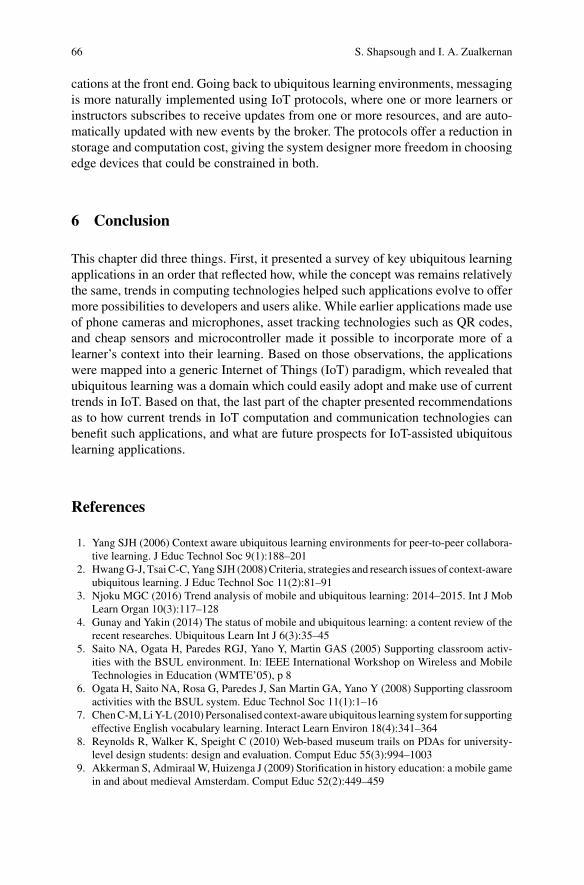
66 S. Shapsough and I. A. Zualkernan
cations at the front end. Going back to ubiquitous learning environments, messagingis more naturally implemented using IoT protocols, where one or more learners orinstructors subscribes to receive updates from one or more resources, and are auto-matically updated with new events by the broker. The protocols offer a reduction instorage and computation cost, giving the system designer more freedom in choosingedge devices that could be constrained in both.
6 Conclusion
This chapter did three things. First, it presented a survey of key ubiquitous learningapplications in an order that reflected how, while the concept was remains relativelythe same, trends in computing technologies helped such applications evolve to offermore possibilities to developers and users alike. While earlier applications made useof phone cameras and microphones, asset tracking technologies such as QR codes,and cheap sensors and microcontroller made it possible to incorporate more of alearner’s context into their learning. Based on those observations, the applicationswere mapped into a generic Internet of Things (IoT) paradigm, which revealed thatubiquitous learning was a domain which could easily adopt and make use of currenttrends in IoT. Based on that, the last part of the chapter presented recommendationsas to how current trends in IoT computation and communication technologies canbenefit such applications, and what are future prospects for IoT-assisted ubiquitouslearning applications.
References
1. Yang SJH (2006) Context aware ubiquitous learning environments for peer-to-peer collabora-tive learning. J Educ Technol Soc 9(1):188–201
2. HwangG-J, Tsai C-C,YangSJH (2008)Criteria, strategies and research issues of context-awareubiquitous learning. J Educ Technol Soc 11(2):81–91
3. Njoku MGC (2016) Trend analysis of mobile and ubiquitous learning: 2014–2015. Int J MobLearn Organ 10(3):117–128
4. Gunay and Yakin (2014) The status of mobile and ubiquitous learning: a content review of therecent researches. Ubiquitous Learn Int J 6(3):35–45
5. Saito NA, Ogata H, Paredes RGJ, Yano Y, Martin GAS (2005) Supporting classroom activ-ities with the BSUL environment. In: IEEE International Workshop on Wireless and MobileTechnologies in Education (WMTE’05), p 8
6. Ogata H, Saito NA, Rosa G, Paredes J, San Martin GA, Yano Y (2008) Supporting classroomactivities with the BSUL system. Educ Technol Soc 11(1):1–16
7. ChenC-M,LiY-L (2010)Personalised context-aware ubiquitous learning system for supportingeffective English vocabulary learning. Interact Learn Environ 18(4):341–364
8. Reynolds R, Walker K, Speight C (2010) Web-based museum trails on PDAs for university-level design students: design and evaluation. Comput Educ 55(3):994–1003
9. Akkerman S, AdmiraalW, Huizenga J (2009) Storification in history education: a mobile gamein and about medieval Amsterdam. Comput Educ 52(2):449–459

IoT for Ubiquitous Learning Applications: Current Trends … 67
10. Liu T-Y, Chu Y-L (2010) Using ubiquitous games in an English listening and speaking course:impact on learning outcomes and motivation. Comput Educ 55(2):630–643
11. Chin KY, Lee KF, Chen YL (2015) Impact on student motivation by using a QR-based U-learningmaterial production system to create authentic learning experiences. IEEETrans LearnTechnol 8(4):367–382
12. Chen CH, Hwang GJ (2015) Improving learning achievements, motivations and flow with aprogressive prompt-based mobile gaming approach. In: 2015 IIAI 4th international congresson advanced applied informatics, 2015, pp 297–302
13. Hung I-C, Yang X-J, Fang W-C, Hwang G-J, Chen N-S (2014) A context-aware video promptapproach to improving students’ in-field reflection levels. Comput Educ 70:80–91
14. Liu T-Y, Tan T-H, Chu Y-L (2009) Outdoor natural science learning with an RFID-supportedimmersive ubiquitous learning environment. J Educ Technol Soc 12(4):161–175
15. Gómez J, Huete JF, Hoyos O, Perez L, Grigori D (2013) Interaction system based on Internetof Things as support for education. Procedia Comput Sci 21:132–139
16. Kong XTR, Chen GW, Huang GQ, Luo H (2017) Ubiquitous auction learning system withTELD (Teaching by Examples and Learning by Doing) approach: a quasi-experimental study.Comput Educ 111:144–157
17. RFID-enabled learning supply chain: a smart pedagogical environment for TELD. Research-Gate. [Online]. Available: https://www.researchgate.net/publication/287481361_RFID-enabled_learning_supply_chain_A_smart_pedagogical_environment_for_TELD. Accessed 17 July2017
18. Zualkernan IA, Al-Khunaizi N, Najar S, Nour N (2010) Prête-à-apprendre+: towards ubiq-uitous wearable learning. In: 2010 10th IEEE international conference on advanced learningtechnologies, pp 740–741
19. Arroyo I, Zualkernan IA, Woolf BP (2011) Hoodies and barrels: using a hide-and-seek ubiq-uitous game to teach mathematics. In: Advanced learning technologies (ICALT), 2011 11thIEEE international conference on, pp 295–299
20. Putjorn P, Ang CS Farzin D (2015) Learning IoT without the ‘I’-educational Internet of Thingsin a developing context. In: Proceedings of the 2015 workshop on do-it-yourself networking:an interdisciplinary approach, New York, NY, USA, 2015, pp 11–13
21. Shapsough S, Amin S, Ahmed H, Zualkernan I, Mitchell K (2015) ARCHI-PODS: ubiqui-tous learning technology to teach architectural design principles to architecture students. In:Presented at the INTED2015, 2015, pp 4338–4347
22. Particle [Online]. Available: https://www.particle.io/23. Arduino—Home24. Overview| Adafruit Feather 32u4 Bluefruit LE|Adafruit Learning System [Online]. Available:
https://learn.adafruit.com/adafruit-feather-32u4-bluefruit-le/overview. Accessed Mar 26 201725. Raspberry Pi—Teach, Learn, and Make with Raspberry Pi26. N. T. Co, “Get C.H.I.P. and C.H.I.P. Pro—the smarter way to build smart things. Next Thing
Co. [Online]. Available: https://getchip.com/pages/chip. Accessed Mar 25 201727. BeagleBoard.org—black [Online]. Available: https://beagleboard.org/black. Accessed Mar 26
201728. ODROID|Hardkernel [Online]. Available: http://www.hardkernel.com/main/main.php.
Accessed Mar 26 201729. Samsung ARTIK IoT Platform—Samsung ARTIK 1020 IoT Module [Online]. Available:
https://www.artik.io/modules/artik-1020/. Accessed Apr 02 201730. The Intel® Edison Module|IoT|Intel® Software [Online]. Available: https://software.intel.co
m/en-us/iot/hardware/edison. Accessed Mar 25 201731. Chen NS, Hung IC,Wei CW, Developing ubiquitous learning system with robots for children’s
learning. In: 2010 Third IEEE international conference on digital game and intelligent toyenhanced learning, 2010, pp 61–68
32. Bedek MA, Firssova O, Stefanova EP, Prinsen F, Chaimala F (2015) User-driven developmentof an inquiry-based learning platform: qualitative formative evaluations in weSPOT. InteractDesign Architecture(s) 23:122–139

68 S. Shapsough and I. A. Zualkernan
33. Shapsough S, Shapsough SE, Hassan M, Zualkernan I (2016) IoT technologies to enhanceprecision and response time of mobile-based educational assessments. In: Presented at the2016 international conference on computational science and computational intelligenc, LasVegas, USA
34. Suarez A, Ternier S, Kalz M, Specht M, GPIM: Google glassware for inquiry-based learning.In: Open learning and teaching in educational communities. Springer, pp 530–533
35. Suarez A, Ternier S, Kalz M, Specht M, GPIM: Google glassware for inquiry-based learning.Interact Design Architecture(s) 24:100–110
36. Abdullah F, Ward R (2016) Developing a general extended technology acceptance model fore-learning (GETAMEL) by analysing commonly used external factors. Comput Hum Behav56:238–256
37. Chang H-Y et al (2015) A review of features of technology-supported learning environmentsbased on participants’ perceptions. Comput Hum Behav 53:223–237
38. Atzori L, Iera A, Morabito G (2010) The internet of things: a survey. Comput Netw54(15):2787–2805
39. Mashal I, Alsaryrah O, Chung T-Y, Yang C-Z, Kuo W-H, Agrawal DP (2015) Choices forinteraction with things on Internet and underlying issues. Ad Hoc Netw 28:68–90
40. Ray PP A survey on Internet of Things architectures. J King Saud University Comput Info Sci41. Guth J, Breitenbücher U, Falkenthal M, Leymann F, Reinfurt L (2016) Comparison of IoT
platform architectures: a field study based on a reference architecture. In: 2016 cloudificationof the Internet of Things (CIoT), pp 1–6
42. Gubbi J, Buyya R, Marusic S, Palaniswami M (2013) Internet of Things (IoT): a vision,architectural elements, and future directions. Future Gener Comput Syst 29(7):1645–1660
43. Bedek MA, Firssova O, Stefanova EP, Prinsen F, Chaimala F (2015) User-driven developmentof an inquiry-based learning platform: qualitative formative evaluations in weSPOT. InteractDesign Architecture(s) 23:122–139
44. MongoDB for GIANT Ideas [Online]. Available: https://www.mongodb.org/45. Apache CouchDB [Online]. Available: http://couchdb.apache.org/

Trust Management Approachesin Mobile Adhoc Networks
R. Vijayan and N. Jeyanthi
Abstract Mobile Adhoc Networks are a collection of mobile nodes interconnectedby wireless media links. Here nodes misconduct owing to topology variations,exposed medium, short signal range, the absence of centralized approach and limitedEnergy. Node misbehaviors are critical concerns for routing in MANET. Under thegiven scenario, the nodes in MANET might decline to collaborate by not forward-ing data with others for egoistic causes. However, it mandated that the nodes mustcollaborate or cooperate to route the packets towards the appropriate destination.The trust relationship among the nodes in a disseminated way helps in detecting themisbehaviors/selfish nodes. To avoid the misbehaving nodes from routing three trustmanagement approaches has been proposed. In the first approach, Trust approachfor Discovering and Quarantine the Misbehaviors (TDQM), the number of droppedpackets as a parameter in the neighbor observation trust evaluation. Energy utilizedfor forwarding all types of packets, packet integrity, and neighbor observation, trustis recommended for trust evaluation. A node with high trust elected as a certificationagency to release certificates for routing packets between the desired nodes. More-over, untrustworthy nodes trust, computed is redeemed and isolated from routing. ASecond approach proposed is Context residual Energy Based Trust Management inMANET (CEBTM), Retrieved context data like residual Energy and packets drop-ping of the nodes considered with weights for neighbor observation trust evaluationand reputation-based trust based on fuzzy for analysis. Revocation of trust of agenerated negative alarm is verified based on the probability of reliability. In theEnhancing Trust in a MANET using trust and dynamic with Energy Efficient Mul-tipath Routing Protocol approach (ETMRP), evaluating nodes parameters intimacy,Energy, packet delivery and co-ordination as context values over time. Here trust
R. Vijayan (B)Department of Information Technology, School of Information Technology and Engineering, VITUniversity, Vellore 632014, Tamil Nadu, Indiae-mail: [email protected]
N. JeyanthiDepartment of Computer Application and Creative Media, School of Information Technology andEngineering, VIT University, Vellore 632014, Tamil Nadu, Indiae-mail: [email protected]
© Springer Nature Switzerland AG 2019N. Jeyanthi et al. (eds.), Ubiquitous Computing and Computing Security of IoT,Studies in Big Data 47, https://doi.org/10.1007/978-3-030-01566-4_4
69

70 R. Vijayan and N. Jeyanthi
based path chosen by Energy efficient multipath routing. The simulation results ofthe proposed approaches provide healthier packet delivery ratio, reduced end-to-enddelay as compared with other methods.
Keywords Trust management · Trust framework · Trust misbehaviorsContext-based trust · Trust computation in MANETTrust and dynamic with energy efficient multipath routing protocol
1 Introduction
The concept of trust is necessary to communicate, and network protocol designerswhere establishing trust relationships amongparticipatingnodes is critical in enablingcollaborative optimization of system metrics. Trust as “a set of relations amongentities that participate in a protocol”. The attackers also attract the unique features ofthe vulnerable medium, changing topology, limited battery power, limited physicalsecurity MANETs. In common, uncooperative nodes in MANETs may be of twotypes: malicious nodes and selfish nodes. A self-regarding node, on the other hand,is an economically rational node whose objective is to maximize its welfare, definedas the benefit of its actions minus the cost of its operations. A node consumes somecost for forwarding a message; a selfish node will need an incentive for doing it [1].
The term Trust originally derives from social sciences and is defined as the degreeof subjective belief about the behaviors of a particular node [2].MattBlaze announcedthe word Trust Management and recognize it as a detached constituent of securityservices in networks and clarified that Trust management provides a unified approachto specify and interpret security policies, credentials, and relationships.
Trust is definite as a degree of belief about the behavior of other units. Cre-ating trust relationships among participating nodes is vital that non-cooperative ordestructive behavior will hurt their trust value or reputation. Motivation towards trustis from support in decision-making to improve security and robustness, Misbehaviordetection, Adaptation to risk. MANETs must deliver numerous levels of securityassurances to diverse applications for their successful placement usage. However,due to their wireless links and lack of central management, MANETs have far moresignificant security concerns than conventional networks. There is a need for thenode in MANET to be trusted or not for various applications, route discovery andother. Multiple attacks exist in MANET. An active attack is attacking when a mis-behaving node has to bear some energy costs. On the other hand, passive attacks aremainly due to lack of cooperation with the purpose of saving energy selfishly. Nodesthat perform ongoing attacks with the intention of harming other nodes by causingnetwork outage are measured as malicious while nodes that make passive attackswith the aim of saving battery life for their communications are deemed to be selfish.

Trust Management Approaches in Mobile Adhoc Networks 71
2 Literature Review
CONFIDANT is a mechanism which supports cooperation in ad hoc networks bydetecting and isolating malicious nodes using direct observations and recommenda-tions. Themodel cannot prevent the dissemination of false recommendation, and neg-ative recommendation is the only information exchanged between nodes. Besides, ituses only single trust metric evaluation based on the cooperation of nodes in packetforwarding [3]. The model omits some critical evaluation metrics such as energy,delay and social properties in evaluating nodes’ trust. Propose the CORE model,which has a watchdog component complemented by a reputation system that dis-tinguishes between three types of information such as subjective reputation usingobservations, positive indirect reputation by others, and functional reputation usingtask-specific behavior. Consequently, this can lead to decreased efficiency of thesystem because nodes cannot exchange bad experiences from the misbehaving onesin the network. Also, CORE cannot be resilient against a ballot-stuffing attack as itleaves ways for misbehaving nodes to collude and gain low high ratings [4].
Authors in [5], has proposed RFSTrust, a trust model based on fuzzy recommen-dation similarity, which is presented to measure and evaluate the trustworthinessof nodes. They use similarity theory to assess the recommendation relationshipsbetween nodes. That is, the higher the degree of similarity between the evaluatingnode and the recommending node, the more consistent is the evaluation between thetwo nodes. In this model, only one type of situation considered when a selfish nodeattack is present. Chen et al. [6], present a fuzzy trust model for peer-to-peer net-works. The design includes two phases; recommendation trust and direct trust. Theprimary focus of the recommendation trust phase is the extraction of the trust linkand computation of recommendation trust degree using the fuzzy decision-makingmethod. Various sets based on the fuzzy decision method are used to obtain a fuzzytrust evaluation metric, while the focus of the direct trust phase is mainly on updatingthe direct trust degree using peers experience and recommendation.
Context-Aware Detection is the mechanism proposed by Paul and Westhoff [7],relates nodes accusations to a unique route discovery process and a particular period.They use for monitoring a combination of un-keyed hash verification of routing mes-sages, and misbehavior detection by making a comparison between a cached routingpacket and overheard packets, thereby detecting tampering from the path requestheader. This approach enables the detection of several types of attack and attacker,and also rejects ineffective route information at as early a stage as possible. Li et al.[8], have used various contextual information, such as channel status, battery status,and weather condition, are collected and then used to determine whether the misbe-havior is likely a result of a malicious activity or not. Luo et al. [9], Here the com-bines direct trust and trust recommendation information. Trust collaborative filteringto allow nodes to represent and reason with uncertainty and imprecise informationregarding other nodes trustworthiness. There is no cooperation risk measurementrelying on the approximate estimation of a node’s behavior instead of detailed andcrisp data.

72 R. Vijayan and N. Jeyanthi
Xia et al. [10], propose Trust relationship based on weight method and fuzzy logicrule for misbehavior detection. However, no attributes that influence the surroundingenvironment of the node like expected transmission count on lossy wireless links,energy, packet drop. Moreover, no adaptive trust-level classification of nodes.Trustcomputation not done for different context under different node encountered at atime. Energy Efficient and Trust-Based Node-Disjoint Multipath Routing ProtocolforWSN a node separatemultipath routing protocol which is vitality effective as wellas trust-based [11]. Survey of different Trust based QoS mindful Routing Protocol inMANET trusts based and QoS-aware steering convention is performed. The inves-tigation of various trust-based and QoS-aware AODV conventions that are utilizingtrusted framework and trust models shown for keeping the assaults and rowdinessfrom vindictive nodes in the network. The execution of trust-based routing resolutionhas been examined that works productively and can utilize as a part of different uti-lizations of MANETs for enhancing the security performance of the system. AODVconvention is employed fundamentally for the course revelation and course upkeepwhen the connection fizzles, consequently is for the most part utilized as a part ofthe routing resolutions [12].
3 TDQM-Trust Scheme for Discovering and Quarantinethe Misbehaviors in MANET
In this scheme, direct trust calculation of a node to another node means calculatingthe trust value and confidence levels from the events that are directly experienced ormonitored between those two nodes. Recommendation trust or indirect trust (IDT)means the trust value taken from other nodes. This confidence value is maybe adirect trust value on that node or the indirect trust value of that node taken fromother nodes. In this scheme calculation of direct and indirect confidence is alsoconsidered the energy utilization factor of the node that is calculated based on thebattery consumption by a node. Packet modification is a significant security issue inMANETs, so a node checked if it tries to alter or tamper the packet contents and thispacket integrity factor is considered in the trust calculation making trust computationvital in the proposed framework as shown in Fig. 1.
3.1 Energy Auditor
In every node power expended for forwarding the packets to neighbor nodes. Lateron, communication starts energy consumption also leads. This expenditure of energyis more for trusted nodes because they have to receive as well as forward the packetsto its neighbors. However, is a case of selfish nodes energy utilization is slightlylow, they only receive data packets, they will not forward packets to neighbors. So

Trust Management Approaches in Mobile Adhoc Networks 73
Fig. 1 Proposed TDQM trust scheme
after completion of communication trusted nodes have less energy, selfish nodeshave somewhat higher energy than other nodes. This power consumption is alsodepending on the routing protocol.
To calculate the energy used by a node the initial node configuration is necessary.In primary node configuration initial energy, ideal power consumption, receivingpower consumption, transmission energy consumption all these details should bespecified.
The nodes Battery power is limited and non-renewable resource in wireless ad hocnetworks. Due to limited resource availability, nodes behave selfishly by saving thebattery power without forwarding the packets. An energy audit monitors the energyspent at each node. The total node energy expenditure at a node due to another nodein the network can calculate as follows.
EValue � ρn>0(ρX≡YETack + ρX ��YERack ) + ρm>0(ρX≡YETPck + ρX ��YERPCK) (1)
where
EValve � Energy consumed at node Y due to node XEValve � Energy spent for one acknowledgment

74 R. Vijayan and N. Jeyanthi
ETack � Energy consumption for transmission of one data packetERack � Energy Spent for reception of one ACK packetERpck � Energy spent for the reception of one data packet.
3.2 Direct Trust Monitor
Neighbor observation estimation comes underneath straight observation of neigh-bors. Here, each node monitors the all the nearby nodes. Any abnormal action dis-covered, invokes an algorithm to determine direct trust value. By neighbors of anode, we mean all the nodes in the network that are the one-hop distance from thenode. The collected data audited, and any deviation from the standard behavior ofa neighbor is used as an indicator for the fair degree of selfishness because this isindependent of past behavior of the neighbor. All the nodes direct trust value of allthe communicating nodes calculated and stored in the trust table of the resultantnode with record names such as node ID, DT value and total trust of the coordinatingnode. The trust value calculated dynamicallywhen new neighborswithin the networkrange and table are updated.
In this direct trust module, the source node will observe the behavior of the targetnode. Here observingmeans collecting the details of the communication of that targetnode. After collecting the total details number of successful, total numbers of failurescalculated. Using those details direct trust value of the destination node is computed.
This module monitors neighbors by passively listening to their communication,every node in the network monitors the behavior of every other neighbor. Identifyingpacket dropped, delayed packet, forwarded packet, and this module use watchdogmechanism to check whether neighbor forwards the packets or drop them. The directtrust monitor audits the collected data. DT agent does trust computation. Node Xwant to calculate the trust value of node Y termed as DTValue(K)
K � S − F (2)
Here S is a function of successful communication metrics, F is a function ofnot successful communication metrics. Evaluation DT on Y, X has to monitor thefollowing statistics. Parameters of the role S are Control packets forwarded, Controlpackets received. Parameters for function F are packet delay, packet drop. K givesthe direct trust value (DTValue) calculated from X on Y.
3.3 Indirect Trust Monitor
The task of the secondary trust monitor is to collect or request the trust related infor-mation of target node from the neighboring nodes. Here one more issue will comein the pictorial manner, from which neighbor, have to collect this trust information.

Trust Management Approaches in Mobile Adhoc Networks 75
The result for this question is a direct trust value of the neighbor. In other words,the trust request of a sink node from neighbors, the trust value of that neighbor nodeconsidered. Choosing of the donor is also done using fuzzy logic. This informationcalled for indirect trust (IDT).
Algorithm:Obtaining Indirect Trust on y from n
i. Node x sends IDTREQ to node(s) n.ii. If node n has direct trust value to y, then it will reply back with IDTREP.iii. Else If and does not bear a direct trust value record it will discard the IDTREQiv. After receiving an IDTREP reply from neighbors consider the trust value of the
node with maximum direct trust value by applying fuzzy logic.v. Integrate all the obtained IDTvalue from neighbors to calculate the Indirect trust
value.
Indirect trust means getting the trust value of required nodes from its neighbors.A recommendation, trust value, the source node will broadcast the request packetregarding the recommendation trust to all its neighboring nodes. Here input of thefuzzy logic is a direct trust value of all the replied neighbors.Among all the neighbors,the node withmaximum trust value chosen, and recommended trust value consideredfor the evaluation indirect trust value of X on node Y denoted as IDTValue.
3.4 Packet Modification Auditor
Packet modification by malicious nodes is a significant security threat. If an inter-mediate node modifies the message content, this amendment can be detected, andthe packet discarded. PMvalue is a positive value at the initial stage, and if there isa modification of request packets by a node, its PMvalue will decrease. Each nodegenerating a message includes a digital signature generated from its private key andall fields except the hop count field. RSA performs signature verification efficientlyand incurs least cost compared to other asymmetric algorithms. The vast discrepancyin the energy costs of sign and verify operations in RSA results from the significantdifference in the sizes of the keys employed. In our proposed scheme RSA algorithmis implemented due to its efficiency and least energy cost over others.
3.5 Trust Aggregator
The functionality of the trust aggregator is to calculate the final trust value FTvalueof the target node using a direct trust, value and recommended trust from the neigh-bors, Energy value and Packet modification value. When the timeout expires, Trust

76 R. Vijayan and N. Jeyanthi
Computation carried out again. Each node the trust value a timestamp assigned Trustaggregator generates a Trust Record Table (TRT) with Node id, trust type and Trustvalue of each node.
FTValue � DTvalue + IDTvalue + PMvalue − Evalue (3)
where
FTvalue � Final trust valueEvalue � Energy valueDTvalue � Direct trust valueIDTvalue � Indirect trust valuePMvalue � Packet modification value.
3.6 Certificate Authority
The Central Authority CAwill be responsible for generating and issuing a certificateto the requesting node. For every new session, a new certificate would generate witha new timestamp TS. The node with maximum trusted value elected as certificateauthorities. Once identified the source node can transmit its ID and obtain certificatesfrom the central authority and begin transmission to the destination node. The trustvalue or timestamp expires the node’s certificate renewed by theCertificateAuthority.
The security provided by electing Trust based Certificate Authority using thehighly trusted node in the range. Certificates are issued by the CA, evaluating thetrust value of each node. This framework ensures only the trusted nodes to acquirecertificates for data exchange isolating the malicious nodes in its range making thesystem trustworthy.
In this scheme, the CA Election algorithm devised, to elect CA node from thegroup of nodes based on the nodes trust value. Each node sends a CA request packet(CAREQ) to announce it as CA. CAREQ consists of node ID and trust value. Whena node of confidence receives a CAREQ, from one of its neighbors, choosing CA.A node with the high trust value elected as a CA. A single mobile node functioningas a CA will bring the entire MANET to a halt if it moves out of the MANET andalso acts as a single point of failure if it becomes compromised. Replacement CAsis being used to prevent this security bottleneck.
CA Reply packet (CAREP) sent back to the requestor node. It consists of nodeID and corresponding nodes trust value. If the requestor node elected as CA node,it maintains the trust value received from the other neighboring nodes and highestamong them will be replacement CA. The Timeout value set to the CA node. Whenthe timer value, perishes or CA node fails, CA election algorithm will be invokedagain.
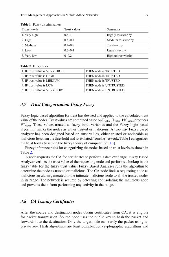
Trust Management Approaches in Mobile Adhoc Networks 77
Table 1 Fuzzy discrimination
Fuzzy levels Trust values Semantics
1. Very high 0.8–1 Highly trustworthy
2. High 0.6–0.8 Medium trustworthy
3. Medium 0.4–0.6 Trustworthy
4. Low 0.2–0.4 Untrustworthy
5. Very low 0–0.2 High untrustworthy
Table 2 Fuzzy rules
1. IF trust value is VERY HIGH THEN node is TRUSTED
2. IF trust value is HIGH THEN node is TRUSTED
3. IF trust value is MEDIUM THEN node is TRUSTED
4. IF trust value is LOW THEN node is UNTRUSTED
5. IF trust value is VERY LOW THEN node is UNTRUSTED
3.7 Trust Categorization Using Fuzzy
Fuzzy logic based algorithm for trust has devised and applied to the calculated trustvalue of the nodes. Trust values are computed based onEvalue, Tvalue, PICvalue producesFTvalue. These values treated as fuzzy input variables and the Fuzzy logic basedalgorithm marks the nodes as either trusted or malicious. A two-way Fuzzy basedanalyzer has been designed based on trust values, either trusted or noticeable asmalicious less than the threshold and its isolated from thenetwork.Table 1 categorizesthe trust levels based on the fuzzy theory of computation [13].
Fuzzy inference rules for categorizing the nodes based on trust levels as shown inTable 2.
A node requests the CA for certificates to perform a data exchange. Fuzzy BasedAnalyzer verifies the trust value of the requesting node and performs a lookup in thefuzzy table for the fuzzy trust value. Fuzzy Based Analyzer runs the algorithm todetermine the node as trusted or malicious. The CA node finds a requesting node asmalicious an alarm generated to the intimate malicious node to all the trusted nodesin its range. The network is secured by detecting and isolating the malicious nodeand prevents them from performing any activity in the range.
3.8 CA Issuing Certificates
After the source and destination nodes obtain certificates from CA, it is eligiblefor packet transmission. Source node uses the public key to hash the packet andforwards it to the destination. Only the target node can verify the packet using itsprivate key. Hash algorithms are least complex for cryptographic algorithms and

78 R. Vijayan and N. Jeyanthi
should incur least energy cost. In this scheme, MD4 is used to hash the packet. Oncethe timestamp value of the certificate expires, the node has to request CA node forthe renewal of licenses.
Certificates issued by the CA node with a timeout value, and once the timeoutvalue of the trusted node expires, it has to request the CA node for the renewal ofcertificates to transmit data packets.
Certificate Exchange Algorithm:
i. Generate Shared Key SKac.ii. Source node request CA E[CREQ(SID,DID,FTValue)SKac]iii. CA node decrypts CREQ looks for SID in ID repository.iv. IF(SID==ID)THENv. CA node verifies for SID and checks for DID in its range.vi. Generate PUx,PRx, PUy,PRy, SKbc,
a. CERT X � SID,PRx,PUy,FTvalue,TS.b. CERT T � DID,PRx,PUy,FTvalue,TS.
vii. CA sends CREP as E[(CERT X)SKac] to source node A.viii. CA sends E[(CERT Y)SKbc] to destination node Y.ix. ELSE DISPLAY(“Transmission not granted”).
wherePUx, PUy � Public Key of node A and B.PRx, PRy � Private Key of node A and B.SKac � Shared Key of Source and CA.SKbc � Shared Key of Destination and CA.SID, DID � Source and Destination ID.
3.9 Malicious Node Detection
Nodes with the fuzzy values as low, very low marked as malicious. Fuzzy BasedAnalyzer invokes the Fuzzy logic based algorithm to detect the malicious nodes. CAnode denies the certificate to themalicious nodes, preventing them from participatingin the network activities. An alarm is generated by the CA node to indicate thenode’s malicious behavior to other trusted nodes in its range, thus isolating the lesstrusted nodes and building a secure system. No suspicious and misbehaving nodescan cause vulnerabilities and threats to the proposed scheme. The proposed schemeismade secure by incorporating trust levels and Fuzzy BasedAnalyzer for CertificateAuthority. FuzzyBasedAnalyzer performs thedefined steps, and if the requestor nodeis TRUSTED, then CA node generates the certificates and sends it to the requestornode. Nodes with the fuzzy values as VERYHIGH, HIGH, andMEDIUM fall in theTRUSTED category. Now with the help of the acquired certificate, the TRUSTED

Trust Management Approaches in Mobile Adhoc Networks 79
node can exchange the data packets. Certificates issued by theCAnodewith a timeoutvalue and once the timeout value of the TRUSTED node expires it has to request theCA node for the renewal of certificates to transmit data packets.
4 Simulation Results and Discussion
Qualnet5.0 network simulator is used to simulate a wireless network with AODVprotocol. A networkmodel has created as shown in the figurewith the help of QualnetSimulator. Six nodes have used in this scenario where Node ID 1, Node ID 2, NodeID 3, Node ID 4, Node ID 5, Node ID 6 connected to wireless network framing aMANET. Node ID 5 is assumed as central authority node and receives the messagefrom both the source and the destination node. An AODV routing protocol has usedin this scenario wherein every node exchanges routing information with the othernodes in the system. Random waypoint mobility has set with all the nodes, and thebehavior of the nodes with mobility is displayed.
The Simulation parameters for six nodes model as shown in Table 3. The packetsent for this model as shown in Fig. 2 and packet received in Fig. 3. The packetdropped nodes for this model as shown in Fig. 4.
The Simulation parameters for twelve node model as shown in Table 4.Secondly, network model has created as shown in Fig. 5 with the help of Qualnet
Simulator twelve nodes have used in this scenario. HereNode ID 1–12, are connectedto wireless network framing a MANET. Node ID 12 is assumed as central authoritynode and receives the message from both the source and the destination node. AnAODV routing protocol has used in this scenario wherein every node exchangesrouting information with the other nodes in the system. Nodes without mobilityin this scenario and probability of detection of malicious nodes with the proposed
Table 3 SimulationParameters-Scenario-I
Parameter Values
MAC IEEE802.11
Routing protocol AODV
Initial Energy 100
Reception Power 1.049 W
Transaction Power 1.6787 W
Idle Power 0.6699 W
Simulation time 1 min
No. of nodes 6
Mobility Model Random waypoint
Traffic type CBR
Payload size 512 bytes

80 R. Vijayan and N. Jeyanthi
Table 4 Simulation Parameters-Scenario-II
Parameter Values
MAC IEEE802.11
Routing protocol AODV
Simulation time 1 min
Initial Energy 100
Reception Power 1.049 W
Transaction Power 1.6787 W
Idle Power 0.6699 W
No of nodes 12
Mobility Model Random Waypoint
Traffic type CBR
Payload size 512 bytes
Fig. 2 Number of data packets sent for six node model
Fig. 3 Number of data packets received for six node model

Trust Management Approaches in Mobile Adhoc Networks 81
Fig. 4 Number of data packets dropped for six node model
Fig. 5 Number of data packets received for twelve node model
Fig. 6 Number of data packets dropped for twelve node model
framework depicted. A randomwaypointmobilitywith all the nodes and the behaviorof the nodes with mobility is displayed as shown in Fig. 6.
The effect of implementation of our approach, Nodes two, three in six model andNode 2, 6, 7, 11 in 12 Node model marked as malicious and isolated.
CONFIDANT determines the value of trust using direct and indirect monitoring.By these observations, it detects the malicious nodes. CONFIDANT additionally

82 R. Vijayan and N. Jeyanthi
Fig. 7 Packet delivery ratio—TDQM versus other trust approaches
introduces an incentive scheme to reward the positive nodes that cooperation the rout-ing process. Here there is more overhead and complexity exit. There is no redemptionmechanism, fake recommendation and convergence of the iteration persist.
SORI that encourages packet forwarding and discipline selfish behavior. Inter-action in a one-hop range in promiscuous mode to find the probability of droppingpackets based on a threshold. However, does not prevent a malicious node fromselectively forwarding packets or the other malicious behavior.
In Fig. 7 compares our proposed TDQM: Trust scheme for Discovering and Quar-antine theMisbehaviors with CONFIDANT and SORI. It observed that our approachTDQM provides higher PDR for more the load offered.
5 CEBTM—Context Residual Energy Based TrustManagement in MANET Network
The proposed approach consists of three modules as shows in Fig. 8, with eachplaying an important role in deriving the final trust for a neighbor node. The modulesare Context Data Manager, Trust Manager, and Trust Monitor. The Context DataManager that takes care of twomajor operations as sending context data ontoneighbornodes and getting context data onto neighbor nodes and computing the weight foreach node at a particular context data. The Trust Manager computes final trust value,rating on the threshold and triggering a negative alarm to Trust monitor. The TrustMonitor verifies the alarm for validity intimates to all neighbor nodes.

Trust Management Approaches in Mobile Adhoc Networks 83
Fig. 8 CEBTM model
5.1 Context Data Manager
The proposed system dynamically computes trust by taking the context data likeResidual Battery energy, Packet Drop Strategy of a node and sending these details tothe neighbor nodes of the network. These details received via a handshaking agentnamed Echo which as shown in the pseudo code below:
Pseudo code for context data evaluation and distribution:
i. Every node identifies its neighboring nodes.ii. Each node finds its context data, i.e., Residual battery energy (Cre,i) and Packet
drop strategy (Cpd,i) and store it in the Context Data Table (CDT).iii. The sequence numbers (RESeq&PDSeq)with zero and the fraction of a lifetime
updated in the Ft.iv. Attaching Residual energy value of the source to the Echo agent and send it to
all the neighbor’s destination nodes with an initial sequence number as zero.v. Attaching Packet Drop Strategy value of the source to the Echo agent and send
it to all the neighbor destination nodes with an initial sequence number as zero.

84 R. Vijayan and N. Jeyanthi
vi. If a target neighbor sends back its context data, then it is retrieved and is storedin the CDT, and the sequence number is updated, and the Ft updated at thecurrent time.
vii. Similarly, the entire neighborhood’s context data are retrieved and stored in theCDT.
Context Data Table (CDT) of a node ‘i’ is represented as a node residual energytuple (NIDires, REseq, Cres,i,Ft) and packet drop tuple (NIDipd, PDSeq, Cpd,i, Ft).
The context data are then used to compute the weight [14] of each node about aparticular context. The computed weight stored in the Context Weight Table (CWT).The CWTgets updated after every fraction time. Theweight is computed using Eq. 4.
Weight, Wi,c � Context data ‘c’ of node ‘i’
Summation of values of all nodes of context ‘c’(4)
where ‘i’ is the node for which weight is to be computed, c’ is the context data.This weight of a node for a particular context is the ratio of the context value of
the node to the summation of all the context values of all nodes to particular contexts.
5.2 Trust Manager
The weight of each node in a particular context is then used to compute the trust ineach node in the specific context.
Context Weight Table (CWT) of a node ‘i’ is represented as a tuple (NIDi, Wi,res,Wi,pd),
where, NIDi—Node ID, Wi,res—Weight for the context Residual Energy,Wi,pd—Weight for the context Packet Drop Strategy
Direct Trust of node ‘j′ on ‘i′ DTci,j �
n∑
c�1
Wi,c × Ft (5)
FractionTime, Ft � tstc/∑n
c�1tsc (6)
tst � current time − FLT for a particular Node ′j’ (7)
where i, j is nodes in the network, ‘c’ is the context data Residual Energy and PacketDrop Strategy, Ft is the fraction time. The Direct trust thus computed is then sharedwith the neighbor nodes and tsc is the summation of all tst for a context data ‘c’.For every 180 s, the context data are shared with the neighbors, and the CWT getsupdated. The direct trust [15] value that is computed using Eq. 5 by each node aboutthe context data that it represents is computed. The direct trust value computed isstored in the Direct Trust Table (DTT). The DTT is maintained by each node in thenetwork regarding the neighbor nodes.

Trust Management Approaches in Mobile Adhoc Networks 85
Direct trust table (DTT) of a node ‘i’ is represented as a tuple (NIDi, DTresi,j , DT
pdi,j ,
FSTVi),where NIDi—Node ID, DTres
i,j —Direct Trust for Residual Energy, DTpdi,j—Direct
Trust for Packet Drop Strategy, FSTVi—Final Source Trust Value.The average of the direct trust computed for each context data are calculated, and
the resulting value is the final source trust value of a node calculated by it. This finalsource trust value stored in the DTT. The final source trust values of each node alongwith its node IDs are then shared with the neighbor nodes via the Echo agent andstored in the Final Node Trust Table (FNTT) of the node.
Final node trust table (FNTT) of a node ‘i’ is represented as a tuple (SNIDi, FSTVj,FNTVj,i), Where SNIDi—Source Node ID, FSTVi—Final Source Trust Value of anode ‘j’, FNTVj,i—Final Node Trust Value.
In FNTT, the Source Node ID is the Node ID from which the Final Trust Valuesent, and Final Source Trust Value of a node ‘j’ is the node to which the Source Nodehas computed the Final Source Trust Value. Finally, the average of the Final NodeTrust Values of each neighbor node and its own Final Source Trust Node is computedusing Eq. 8 and is stored in a Final Trust Table (FTT).
Final Trust V alue � FSTVi + FNTVj,i
n(8)
Final trust table (FTT) of a node ‘i’ is represented as a tuple (NIDi, FTVi,).where, NIDi—Node ID, FTVi—Final Trust value of a node ‘i’, The FTT is then
sent to the Fuzzy Filter to check whether the computed final trust can be trusted ornot.
5.3 Fuzzy Analysis
The fuzzy filter analyzes the Final Trust calculated by the node and done in a series ofsteps shown below. The Final Trust Value computed is checked with the ReliabilityTable.
Pseudo code for final trust verification:
i. The Context data and the Final Trust Value then verified with the Reliabilitytable, and the reliability value is derived.
ii. If the Reliability value is 1.0, then the node is most trusted of.iii. Else if it is between 1.0 and 0.5, then the node can be trusted.iv. Else if the Reliability value is 0.4, then the node can be trusted with some
exceptions.v. Else if the Reliability value is less than 0.4, then the node is not trusted the
untrustworthy node is sent for revocation to the Trust Monitor of other neighbornodes via Echo agent.

86 R. Vijayan and N. Jeyanthi
The reliability of node j at time t, denoted by Rj(t), is the probability that nodej meets the required trust level for mission execution over time [0, t], calculated asfollows [16]:
Rj(t) � {0} if Tj(t′) � 0 for any t′ ≤ t (9)
Rj(t) � {E[Tj
(t′)]}
for t′ ≤ t otherwise (10)
In Eqs. 9 and 10 where t is the current time point and t′ ≤ t is a past time point asshown in Table 5.
5.4 Trust Monitor
The untrusted node that reports the untrusted is verified with the trust value that ithas computed on its own. For example, if node ‘i’ reports to its neighbor that node‘j’ is non-trusted to neighbor node ‘k’, then node ‘k’ analyses the trust which it hascomputed on node ‘i’ moreover, if the reliability value is above 0.7, then node ‘j’ isdeclared non-trusted, and the CDT updated as ‘null.’
5.5 Echo Agent
The Echo agent is a two-way handshaking agent that exchange the context data orinformation between a source node and a destination neighbor node. The Echo agentis one hop away and is modified by each destination node to send it back to the nodeof origin with the relevant data.
The Echo agent used for data exchange in sending context data to neighbor nodes,requesting context data from neighbor nodes, sending final trust of the source nodeto neighbor nodes and intimation neighbor node about the untrustworthy node.
Table 5 Reliability Table
Trust value Packet dropstrategy
Remainingenergy
Reliability Reliability value
9–10 80–100 80–100 Very very High 1.0
7–8 80–100 80–100 Very High 0.8
5–6 50–79 50–79 High 0.6
3–4 50–79 50–79 Medium 0.4
1–2 50–100 50–100 Low 0.2
0–1 00–40 00–40 Very low 0.0

Trust Management Approaches in Mobile Adhoc Networks 87
5.6 Simulation Results and Discussion
The proposed framework is simulated using Network Simulator 2 (NS2) by editingthe existing AODV routing protocol. The Echo agent after being developed patchedwith the NS2.35 and the simulation handled with mobile node scenarios. The scenar-ios are developed under NS2.35 and are simulated under Linux environment Ubuntu10.05. The resulting final trust is plotted using gnu plot to show the level of trustwor-thy and untrustworthy nodes in the simulated scenario. Table 6 shows the scenarioI, where the 15 mobile nodes considered. The scenario uses energy model to ana-lyze the amount of residual energy present in the node. All the energy parametersspecified in the table.
Table 7 shows the scenario II, where the 75mobile nodes considered. The scenariouses Energy model and other mobility models to analyze the amount of residualenergy present in the node and the mobility of the particular nodes respectively. Allthe energy parameters specified in the table.
Table 6 Simulation Parameters for Scenario I
Parameter Value
MAC IEEE 802.11
Routing protocol AODV
Models included Energy model
Initial energy 100
Simulation area 300 × 300
Reception power 35.28e−3
Transaction power 31.32e−3
Idle power 712e−6
Nodes 15 with mobility
Table 7 Simulation parameters for Scenario II
Parameter Value
MAC IEEE 802.11
Antenna Omni antenna
Models included Energy model, random way point withwrapping, random way point with steady state
Initial energy 100
Simulation area 1700 × 1700
Reception power 1.049 W
Transaction power 1.6787 W
Idle power 0.6699 W
Nodes 75 with mobility

88 R. Vijayan and N. Jeyanthi
Fig. 9 Trust for scenario
Fig. 10 Trusts for scenario II
Figure 9 shows the resultant final trust for each node for scenario I. Figure 3 showsthe resultant final trust for each node for scenario II. Figures 9 and 10 shows the x-axis the Number of nodes considered for the scenario and y-axis showing the FinalTrust for each node. The trust values will then compared with the reliability table,and the CDT maintained by each node to find the reliability value of each neighbornode. By analyzing the above two figures, the progressive trust values of the nodeswere computed precisely for more number nodes in the MANET by considering thecontext parameter of residual energy and packet drop strategy.
Figure 11 compares our proposed CEBTM: Context Residual Energy Based TrustManagement in MANET with CONFIDANT, CORE, and TAODV. It observed thatour proposed approach provides higher PDR for more the load offered.
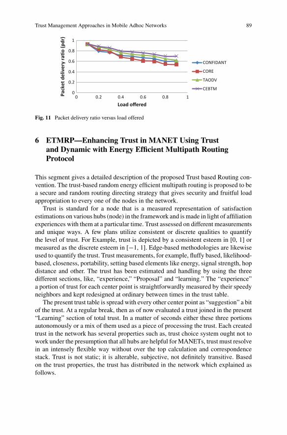
Trust Management Approaches in Mobile Adhoc Networks 89
0
0.2
0.4
0.6
0.8
1
0 0.2 0.4 0.6 0.8 1 Pack
et d
eliv
ery
rao
(pdr
)
Load offered
CONFIDANT
CORE
TAODV
CEBTM
Fig. 11 Packet delivery ratio versus load offered
6 ETMRP—Enhancing Trust in MANET Using Trustand Dynamic with Energy Efficient Multipath RoutingProtocol
This segment gives a detailed description of the proposed Trust based Routing con-vention. The trust-based random energy efficient multipath routing is proposed to bea secure and random routing directing strategy that gives security and fruitful loadappropriation to every one of the nodes in the network.
Trust is standard for a node that is a measured representation of satisfactionestimations on various hubs (node) in the framework and ismade in light of affiliationexperiences with them at a particular time. Trust assessed on different measurementsand unique ways. A few plans utilize consistent or discrete qualities to quantifythe level of trust. For Example, trust is depicted by a consistent esteem in [0, 1] ormeasured as the discrete esteem in [−1, 1]. Edge-based methodologies are likewiseused to quantify the trust. Trust measurements, for example, fluffy based, likelihood-based, closeness, portability, setting based elements like energy, signal strength, hopdistance and other. The trust has been estimated and handling by using the threedifferent sections, like, “experience,” “Proposal” and “learning.” The “experience”a portion of trust for each center point is straightforwardly measured by their speedyneighbors and kept redesigned at ordinary between times in the trust table.
The present trust table is spread with every other center point as “suggestion” a bitof the trust. At a regular break, then as of now evaluated a trust joined in the present“Learning” section of total trust. In a matter of seconds either these three portionsautonomously or a mix of them used as a piece of processing the trust. Each createdtrust in the network has several properties such as, trust choice system ought not towork under the presumption that all hubs are helpful forMANETs, trust must resolvein an intensely flexible way without over the top calculation and correspondencestack. Trust is not static; it is alterable, subjective, not definitely transitive. Basedon the trust properties, the trust has distributed in the network which explained asfollows.

90 R. Vijayan and N. Jeyanthi
6.1 Distributed Trust Evaluations
Distributed trust assessment can be named: neighbor detecting (coordinate trust),proposals based trust (roundabout trust), and a half and half technique [17]. In con-veyed specially appointed systems, trust levels conceived from the investigation ofgathering information from perceptions for particular activities. It could log thata specific node advances a few packages as typical, and after that drops differentbundles. It could get this through direct neighbor detecting and figure trust fromdirect experience. Confidence among prompt neighboring hubs is known as imme-diate trust and required for situations where a trust relationship framed between twohubs without past communications. Then the connection between the node helps todetermine the trust level assessment from the hub and about Node b, Ta(b) (as itsvery ownweighted total trust (monitor) and the proposals of neighbors. The essentialcondition is
Ta(b) � (1 − α)Ea(b) + αRa(b) (11)
where the variable Ea(b), that ranges from [0,1], says to the trust hub a has on nodeb construct just with respect to its own particular perceptions and Ra(b), that reachesfrom [0,1], is the total estimated of the proposals from every single other neighbor,The variable α, that reaches from [0, 1], is a parameter in our model that permitsnodes to choice the most pertinent element. The estimation of (b) is given by
Ea(b) � βET(b) + (1 − β)Ta(b) (12)
where (b) expresses to the trust esteem got by the judgment of the activities of aneighbor performed by the Classifier segment, and the variable ET(b) gives the lasttrust level esteem put away in the Trust Table. The variable β, extents from [0, 1],that permits distinctive weights for the elements of the condition, selecting whichcomponent is the more pertinent at a given moment. Equations 11 and 12 depicthow the Trust Calculator consolidates the data from the Experience Calculator ((b)),the Recommendation Calculator (Ra(b)), and the Trust Table (T a(b)) to determine atrust level. The formed trust has been managed by using the following phases whichavoids the intermediate attacks present in the network.
6.2 Trust Management
The developed trust has been organized and administered by applying the Trustcomputations, Trust aggregation, Trust propagation andTrust prediction stageswhichexplained as follows.

Trust Management Approaches in Mobile Adhoc Networks 91
6.2.1 Trust Aggregation
Like most trust aggregation protocols for MANETs, consider both direct trust androundabout trust. That is, the hub assesses hub j at the time by direct perceptions andcircuitous suggestions.Coordinate perceptions are immediate confirmations gatheredby hub toward hub j over the time interim [t −dδt,], when hub i and hub j are1-bounce neighbors at time ‘t’ (Parvathi Raj and Krishnan [18]). Here �t is thetrust overhaul interim and dis an outline parameter determining the extent to whichlate cooperation encounters would add to intimacy. Go back similarly as t � 0,that is, d � t/�t, if all connection encounters are considered similarly essential.Roundabout recommendations are aberrant confirmations given to hub I by a subsetof 1-bounce neighbors chose in light of two systems against slandering attacks: edgebased separating bywhich just reliable recommenderswith trust higher than a smallerthan normal mum trust edge are qualified as recommenders, and (b) significancebased trust by which just recommenders with high trust in trust segment X arequalified as recommenders to give suggestions about a trustee’s trust part X.
The node to figure its push toward hub j, Ti,j(t) where X is a trust segment by:
Ti(t) � β1Ti,j direct, X (t) + β2Ti,j in direct, X (t) (13)
NowEq. 13, β1 is a parameter tomeasure node i’s data toward hub ‘j’ at time t, i.e.,“coordinate observations” or “self-data” and β2 is a parameter to weigh backhandeddata from recommenders, i.e., “data from others,” with β1 + β2 � 1.
6.2.2 Trust Propagation
Trust estimation on a specific node by whatever other node brings about a cost ofassets. These assets, particularly inMANETs, can be constrained. A specific end goalto lessen assets spent on reconsideration of trust by different hubs decreased if thefigured trust gets propagated in the systemTrust engendering can be ofmulti-bounce.Trust proliferation depends on the transitive property of the trust. The center variableconsidered for trust propagation is collaboration in the system in transporting thevisitor data.
6.2.3 Trust Prediction
Trust prediction is a technique for anticipating conceivably deep trust between nodesutilizing the present and past conduct of nodes. Furthermore, the suggestions gotfrom different nodes. A trust forecast framework, a necessity ought to be fulfilled,for example, if an exchange is unsuccessful, however, the framework predicts that itwould be efficient results in a false positive where a fruitful exchange that is predictedto be unsafe by the framework is a false negative.

92 R. Vijayan and N. Jeyanthi
6.2.4 Trust Formation
Characterize trust parameters utilized in the trust development convention design.The framework can find and apply the best trust arrangement parameters to boostapplication execution, given the operational profile as information. The subjectivetrust estimation of (node) hub j as assessed by the hub at time t, meant as Ti,j(t) alongthese lines is processed by hub a weighted normal of closeness, wellbeing, vitality,and coop-helpfulness trust parts. The evaluation is done occasionally in each �tinterim.
Particularly node, it will process Ti,j(t) by:
Ti,j(t) �∑
YTi,j(t)X (14)
where Ti,j(t) is the trust, conviction of node ‘i’ toward node join trust segmentY � intimacy, strength, vitality or helpfulness and X is the weight connectedwith Y. Underneath we utilize the documentation w1:w2:w3:w4 for inti-macy:ealtiness:energy:cooperativeness for notational comfort. For a trust-basedapplication, the best setting of w1:w2:w3:w4 exists to amplify the application execu-tion. For a non-part, say, node j, the trust level Ti,j(t) is the same as its trust level atthe last trust assessment instant t − δt reduced by time rot.
An interestingmetric is the general average “subjective” trust level of hub j, meantby (t), (s assessed by every dynamic hub.Whenwe acquireTi,j(t) fromEq. 14,Tjsub(t)can be figured by:
Tjsub(t) �∑
Ti,j(t) (15)
Consider Tjsub(t) with the “objective” trust of center point j, connoted by T jobj(t),figured in light of bona fide, overall information to see howmuch deviation subjectivetrust appraisal is from target trust evaluation. Specifically, let (t) show the “objective”trust of center join trust portion Y at time ‘t’, which can secure by a numerical model.Then, taking after Eq. 14, (t) is figured by:
Tjobj(t) �∑
YTobj(t)X (16)
Then the exact algorithm for the trust creation is explained as follows [11].
AlgorithmStep 1: Multipath routes from every hub are made out, and routing table for everynode created.Step 2: Calculate the trust among nodes. For this reason, first, calculate no. of fruit-ful packages exchanged between each match of nodes of the considerable numberof ways in a day and age (�t) indicated by succ. pkt(�t). At that point, a figureno. of unsuccessful packets exchanged between each combination of nodes of thesignificant number of ways in a day and age (�t) signified by unsucc. pkt(�t).Currently, Tij, the trust esteem between two nodes i and j for time �t.

Trust Management Approaches in Mobile Adhoc Networks 93
Tij � 10 × succ pkt(�t)
succ pkt(�t) + unsucc pkt(�t)× 1√
unsucc pkt(�t)(17)
The trust value of all the paths calculated as,
Tpmi �k∑
i�1
Ti,i+1 (18)
The average trust value of each path can found as,
Tpmi � (Tpmi/k
)(19)
where k � total no. of nodes in a pathStep 3: The best path is then chosen by the attribute weighing method as,
Pw � (α × (Lowest R.E. value)) +((α−1) × Tpmi
)(20)
α � ConstantStep 4: This path taken by a source node for data transmission.TheMD5 hashworkH is utilized tomakemessage process H(M) at the hub of origin.The hub of origin produces the digital signature, dsign � (H (M))d mod n by encodingthe message process H(M) with its private key d where, n� p * q, p and q are randomprime numbers with p �� q. The source node advances design with information M,(dsign, M) to its neighboring node through the way it takes to achieve sink.A neighboring node on the gathering of (dsign, M) and the way in the informationpackage, confirm the digital signature by looking at a decoded estimation of designmod n with message process H(M). The outline mod n is unscrambled utilizing thekey (e, n) utilizing sender’s open key.Outline mod n � ((H(M))d mod n)e mod n � (H(M))ed mod n By applying LittleFermat’s and Chinese Remainder Theorem to Eq. 20, and verified that
design mod n � H(M) (21)
Step 5: This procedure reworked in each hop of the node-disjoint way amongstsource and goal.
After creating the trust between the nodes present in the system, the informationshould transmit in the network for avoiding the security and energy issues. Then thetransmission is done by applying the Energy Efficient Multipath Routing Protocol.

94 R. Vijayan and N. Jeyanthi
6.3 Energy Efficient Multipath Routing
Themultipath routing initially used in wired networks for its reliability and its abilityto balance traffic load over the network. In recent years, such technique is extendedto wireless ad hoc and sensor networks with objectives to achieve better energyefficiency and network robustness in case of node failures. The multipath routingprotocol is utilized to locate various disjoint ways between a couple of sink andsource nodes. It has three stages, the initialization phase, the paths search phase, andthe data transmission and paths maintenance phase.
6.4 Initialization Phase
The hello message is one of the control messages exchanged between nodes in theinitialization phase. Identifying the neighbors and sink nodes with their forward nodeID, energy and hop count using hello message. Then hello message is first exchangedbetween sink and source nodes, each node has the sink table and the neighboring nodetable updated. Each node then broadcasts a connectivity message to its immediateneighbors to specify the number of sinks that the sender is aware. This messageadditionally incorporates the field sink numbers to determine the number of the sinkthat known by the sender. The following areas give the sink IDs and the hod countto each of them altogether. The receiving node updates the corresponding entry inits neighboring node table.
6.5 Paths Search Phase
This phase initiated when a set of nodes detect the stimulus, and the selected sourcenode begins to send the aggregated data to the sink node. Explore multiple disjointpaths, the source node unicasts one request message to every neighboring node witha distinct route ID. Each node receives the request message, updates its routing andneighbor table, and the intermediate node has to select one of its neighbors to forwardthis request based on that node is not selected for another path and link cost to theneighbor node has to be the lowest among all the available neighbors. The neighbortables are updated at every hop to avoid using this path in the future path search. Afterthe request message reached the sink node, it updates its table of sources and routingtable with forwarding node ID, route ID, forward node energy and path cost. Thesink node sends the assign messages to the source via each of the selected multipath.This message includes the data transmission rate assigned to each path.

Trust Management Approaches in Mobile Adhoc Networks 95
6.6 Data Transmission and Paths Maintenance Phase
After multiple paths discovered, the source node begins to transmit data packets withthe assigned rates on each path. Path maintenance by sink node updates the path costin its routing table for each packet received. The sink node monitors the multiplepaths for change in data rates and path cost for re-distribute the data rates to optimizethe usage of network resources when path cost changes with a threshold. It thenadjusts the traffic flows and notifies the source node with the assign messages if pathfailure occurs and hop count falls below two and sends a reset message to the sourceto start Path search phase.
7 Simulation Results and Discussion
This area presents an analysis of results among the EEMRP, RTSR, and ADOV theproposed. Nature utilized for recreation is NS2. The simulation results including anend to end delay, packet delivery, and packet accuracy introduced used to break downthe proposed calculation with RTSR and AODV.
Measurements used for Simulationmost utilized parameters as a part ofMANETsare an end to end delay, for various numbers of source hubs in the system. The timetaken to send a bundle over the system is known as an end to end delay. The proportionbetween the bundles sent by the source node and the packages got by goal node effectis known as packet delivery ratio as shown in Fig. 12 and Table 8.
The End-to-End Delay (ETED) defined by the time taken for a packet to reachthe node as shown in Fig. 13 and Fig. 14.
Packet delivery ratio (PDR) is the percentage of node successfully receive thepacket at much node speed and node density.
Figure 15 displays the PDR among AOTMDV, LTB-AOMDV, and ETMRP
Fig. 12 End—to—enddelay analysis among RTSR,AODV and proposed

96 R. Vijayan and N. Jeyanthi
Table 8 Simulation parameters for EDMRP
Parameter Value
MAC IEEE 802.11
Antenna Omni antenna
Models included Energy model, random way point withwrapping, random way point with steady state
Initial energy 100
Simulation area 1700 × 1700
Reception power 1.049 W
Transaction power 1.6787 W
Idle power 0.6699 W
Nodes 75 with mobility
Fig. 13 Packet deliveryratio among RTSR, AODV,and ETMRP
Fig. 14 Packet accuracycomparison among RTSR,AODV, and ETMRP
0
200
400
600
800
1000
4 8 12 16 20
speed (m/s)
pack
et a
ccra
cy
proposed
RTSR
AODV

Trust Management Approaches in Mobile Adhoc Networks 97
Fig. 15 Packet delivery ratio among AOTMDV, LTB-AOMDV, and ETMRP
8 Comparison of the TDQM, CEBTM and ETMRP
FEATURES TDQM CEBTM ETMRP
Energy considered Yes, Direct Trust Yes, Direct Trust Yes, Direct Trust
Packet droppingconsidered
Yes, Direct Trust Yes, Direct Trust Yes, Direct Trust
Direct/observationand Reputation trust
Aggregating trust Aggregating contexttrust
Aggregation last trustand recommendationat a time
Context parametersfor trust
No Packet dropped andresidual energy at aninstant of time
Intimacy,unselfishness, energy,and cooperativeness
Weighted computation Yes for DT Yes for context dataand trust
Yes for DT andrecommendation trust
Dynamic changes inTrust value
Yes Yes Yes
Misbehaving nodedetection
Yes and isolate fromrouting.
Yes and isolate fromrouting.
Yes and isolate fromrouting.
Trust revocation Yes Yes Yes
Timestamp forcomputed trust value
Yes Yes Yes
Trust-based Multipathrouting
No No Yes for effectivepacket transmission
Simulation QualNet and NS2 NS2 NS2
98 R. Vijayan and N. Jeyanthi
9 Conclusion
In the first approach can give a sturdy using bearing in mind the particular optionssuch as QoS, mobile and secure the hubs. The central hub would defend the infointerchange by way of permitting the trustworthy objects to take part in the net, quar-antine the malevolent hubs. Integrating two levels of security, Trustworthy, and CAshall build the safe, secure and reliable network. The approach will possibly identifyand quarantine the malicious nodes commencing participating in the transmission.
The secondmodel computes trust using the ever-changing context data of neighbornodes and thus makes it dynamic to any changing scenarios. The context data asresidual energy and packet drop strategy considered for computing the trust of aneighbor node using the Echo agent. The direct trust is calculated by using theweight of the context data of each neighbor and sending it to the neighbor nodesthrough Echo agent further gives the idea of considering of trust of the roundabout.The Final trust evaluated by aggregation of the direct trust by itself, and the trustfrom the neighbor nodes led into the fuzzy filter to the evaluation of the computedtrust. The Reliability table helps to identify the untrustworthy nodes of the system.The neighbor nodes are acknowledged with the untrustworthy node for revocationand making the neighbor nodes aware of its untrustworthy.
The third approach is to supply MANET protocol creators with various viewstaking the concept of trust, an understanding of the possessions that thought-about increating a parameter of trust. The established trust has used for a multipath routingprotocol. At the time of information transmission, the Energy of the node is main-tained also manage the information with secure manner for multiple paths. Then theefficiency of this ETMRP is examined using the delay, packet delivery ratio, andpacket accuracy.
References
1. Sen J (2010) A distributed trust management framework for detecting malicious packet drop-ping nodes in A mobile ad hoc network. Int J Netw Secur Appl 2(4):92–104
2. Chen R, Guo J, Bao F, Cho JH (2014) Trust management in mobile ad hoc networks for biasminimization and application performance maximization. Ad Hoc Netw 19:59–74
3. Buchegger S, Boudec JYL (2002) Performance analysis of the CONFIDANT protocol. In:Proceedings of the 3rd ACM international symposium. Mobile Ad Hoc Network. Computing,pp 226–236
4. Li W, Joshi A, Finin T (2011) SMART: an SVM-based misbehavior detection and trust man-agement framework for mobile ad hoc networks. In: IEEE UMBC tech report, pp 1–12
5. Luo J, Liu X, FanM (2009) A trust model based on a fuzzy recommendation for mobile ad-hocnetworks. Comput Netw 53(14):2396–2407
6. Chen H, Ye Z (2008) Research of P2P trust based on fuzzy decision-making. In: Internationalconference on in computer supported cooperative work in design, pp 793–796
7. Paul K, Westhoff D (2002) Context aware detection of selfish nodes in DSR based ad-hocnetworks. IEEE Proc Veh Technol Conf 4:2424–2429
8. Li W, Joshi A, Finin T (2013) CAST: Context-aware security and trust framework for mobilead-hoc networks using policies. Distrib Parallel Databases 31(2):353–376

Trust Management Approaches in Mobile Adhoc Networks 99
9. Griffiths N, Chao KM, Younas M (2006) Fuzzy trust for peer-to-peer systems. In: IEEE inter-national conference on distributed computing systems workshops, pp 73–73
10. Xia H, Jia Z, Ju L, Li X, Sha EHM (2013) Impact of trust model on on-demand multi-pathrouting in mobile ad hoc networks. Comput Commun 36(9):1078–1093
11. Agrawal R, Khiani S (2013) Energy efficient and trust-based node-disjoint multipath routingprotocol for WSN. Int J Sci Res 4(3):1069–1073
12. Verma J, Shukla PK, PandeyR (2016) Survey of various trust basedQoS-aware routing protocolin MANET. Int J Comput Appl 137(3):34–43
13. Azzedin F, Ridha A, Rizvi A (2007) Fuzzy trust for peer-to-peer based systems. World AcadSci, Eng Technol 27:123–127
14. Rehak M, Pechoucek M (2007) Trust modeling with context representation and generalizedidentities. In: International workshop on cooperative information agents. Springer, Berlin, pp298–312
15. Rathnayake U, Sivaraman V, Boreli R (2011) Environmental context aware trust in mobile P2Pnetworks. In: Local Computer Networks (LCN), 2011 IEEE 36th Conference on, pp 324–332
16. Cho JH, Chen R (2013) On the tradeoff between altruism and selfishness in MANET trustmanagement. Ad Hoc Networks 11(8):2217–34
17. Geetha S, Geetha Ramani G (2014) Survey of trust-based routing protocols in MANET. Int JAdv Res Comput Sci Softw Eng 4(10):604–608
18. Parvathi Raj P, Krishnan K (2015) A novel energy-efficient routing for data intensive MANET.Int J Recent Innov Trends Comput Commun 3(8):5318–5321

Security in Ubiquitous ComputingEnvironment: Vulnerabilities, Attacksand Defenses
C. Shoba Bindu and C. Sasikala
Abstract Ubiquitous computing is a computing paradigm, which enables comput-ing to be appear everywhere using any device, in any location and any format. Itincludes resource constrained mobile and wearable devices, where computations areembedded in the environment (everyday artefacts). Those devices are connected toeach other using infrastructure-based as well as mobile ad hoc networks. Due tothe, resource constraints and limited internet connectivity the traditional securitymechanisms such as Public Key Infrastructure (PKI) and Server centric authentica-tion, are not used in ubiquitous computing. However, to enjoy the numerous benefitsoffered by this computing paradigm, we must address the security issues relatedto this computing. In this chapter, we discuss security issue such as location pri-vacy, Authentication and device pairing and RFID. The major part of this chapteris intended to discuss the security challenges: Vulnerabilities, attacks and possiblesolutions in the Ubiquitous Computing environment.
Keywords Ubiquitous computing · Security · RFID · Location privacy
1 Introduction
After the invention of the first computer, the computing paradigm has constantlybeen evolving and has gone through significant changes over the past decades fromMicrosoft’s slogan computer on every desk to multiple devices for the user. In recentyears, it has led to the development of standards and technologies for wireless com-munications such as WLAN, RFID, LTE, NFC, and all types of mobile, embeddedand wearable devices [1–3]. As a result, in recent years, the perspectives of theubiquitous computing introduced by Mark Weiser in 1988 [4] come into true. He
C. Shoba Bindu (B)Department of CSE, JNTUA College of Engineering, Anantapur, Indiae-mail: [email protected]
C. SasikalaDepartment of CSE, JNT University, Anantapur, India
© Springer Nature Switzerland AG 2019N. Jeyanthi et al. (eds.), Ubiquitous Computing and Computing Security of IoT,Studies in Big Data 47, https://doi.org/10.1007/978-3-030-01566-4_5
101
102 C. Shoba Bindu and C. Sasikala
imagines the world with technologies that are not visible to the user instead of thatthey can be embedded into the environment. For example, smartphones, tablets orsmart watches, smart contact lenses, as well as smart glasses or smart implantablemedical devices, provide universal access to different types of information.
Nowadays, many people use Internet services from their home, office or any fre-quent places they visit. However, many users can access their emails on their mobilephones or receive their services through their Personal Digital Assistants (PDA). Ascomputing becomes more pervasive, people are always expected to access their ser-vices and information at any time and anywhere. It leads to the development of ubiq-uitous computing. However, with the emergence of new technologies and devices,many novel security issues arise. In Ubiquitous Computing, security is importantbecause there are more people than before using software-based devices as part ofeveryday life. Modern mobile devices are used for both personal and professionalcommunication, and also for various types of information such as financial infor-mation, personal text messages, or sensitive information such as photos with mobiledevices, etc.
The revolution has transformed society in many ways. In this chapter, we willdiscuss the security of Ubiquitous Computing. A modern computer is a very com-plex system even an expert also cannot understand it at all levels. When we considera system of many networks instead of a standalone machine and such networkingis spontaneous and not visible such as wireless technology. In addition to the com-plexity of this system, there are many hidden bugs and unexpected interactions thatcause unpredictability and undesirable behavior. Unfortunately, such an error andinteraction can be exploited by the adversary who causes internal damage. However,as networked systems are more extremely embedded in the environment, and thedamage caused by malicious attacks has become more varied. Nowadays, computersecurity can also seriously affect people who do not use computers because they areprobably using them and rely on them without knowing what they are doing.
1.1 Ubiquitous Computing
Ubiquitous Computing (UbiCom) is a computing paradigm, where computing ismade to appear everywhere using any device, in any location and any format. Here,computations are embedded in the environments. With advancements in computerscience and technology, the computer applications are integrated into our everydaylife. The devices worked in the network, and the independent environment has thecapability of communication with humans and with each other. These devices sup-port access to context-aware applications, mobile users, location-aware services andmobile data access. It provides anytime anywhere access to the data services whilemaking the presence of the system invisible to the user.
Three main properties of Ubiquitous computing are [5], distributed computation,context-awareness, and invisibility. The distributed computation refers to the com-puters/systems need to be networked, distributed and transparently accessible, they

Security in Ubiquitous Computing Environment: Vulnerabilities … 103
Fig. 1 Properties ofubiquitous computing [7]
can interact with each other as well as with humans. The context-awareness propertyrefers to optimization of system operation in their physical and human environment,it is necessary to make the systems aware of environmental context. The invisibilityproperty makes the computer interaction with humans should be more hidden. How-ever, the objective ubiquitous computing [6] is to be user-centric that allows users tointeract with the system in a natural and non-intrusive way to assist users in everydaylife. The five core properties of the ubiquitous computing are illustrated Fig. 1. It isnot mandatory for ubiquitous computing solutions to satisfy all five properties butin practice it may support all five properties.
1.2 Security
Security is the major obstacle to adopt any new computing paradigms. Traditionally,the threats to information systems can be classified concerning three fundamentalsecurity properties that they are: confidentiality, which means only authorized userscan read the information. Integrity, it ensures only authorized users can modify theinformation and availability mean ensuring that only authorized users can access anduse the system as intended, without any delays. These are a good starting point tounderstand what’s most important, even though they do not necessarily exhaust allthe desirable security properties of an information system. Generally, in many casespeople automatically assume that the primary security concern is the protectionof confidentiality which means unauthorized users shouldn’t be able to see privatedata. But, integrity is instead more significant that is unauthorized users must notbe able to edit the user privatedata. And the primary concern is about availability,especially when the system integrates several different functions, for example thecollege computer system cannot stop working for more than a week, as it handlesnot only the students’ grades but also the staff payroll, the course timetable, and thelibrary catalog.

104 C. Shoba Bindu and C. Sasikala
You may notice that the previous paragraph has a recurrence of the phrase “au-thorized users”. It appropriately indicates that the foundation upon which the threesecurity objective rest is authentication, means it makes the distinguishing betweenauthorized and unauthorized users of the system. Usually, this foundation usuallyincludes a sequence of three sub-actions: identification, verification and authoriza-tion. Interestingly, in some cases you may not recognize a particular person, but justa role with associated capabilities—e.g., the librarian checks an authorization tokento ensure that this customer is entitled to borrow up to four books, but she does notneed to know about her name and surname to grant her volumes.
This chapter is organized as follows: Sect. 2 explore the security issues in Ubiqui-tous computing such as Location privacy, Sect. 3 discuss the security issues related toRFID Technology, Sect. 4 explains the fundamental security issues in Ubicom suchas authentication, confidentiality, integrity and availability. Finally, Sect. 5 explainsthe Security challenges: vulnerabilities, attacks and Defenses.
2 Security Issues in Ubiquitous Computing
The Ubiquitous computing model uses wireless and mobile infrastructure. Since thisarchitecture plays a major role in how users can interact with ubiquitous servicesand applications. There are many issues related to mobile and wireless infrastructurein the ubiquitous computing environment. We think that more research is necessaryfor this area for deriving the specific role and requirements. The requirements couldinclude a universal or integrated access to various wireless and mobile networks,support for reliable communications, group communications (multicast), and inter-working of these technologies. Many of these issues are not resolved and we believethat they should be covered before the vision of ubiquitous computing come intoreality.
Security is the major issue in ubiquitous computing, as individual, organizationsor groups, are unlikely put their important, personal and mission-critical informa-tion over an infrastructure that is either not secure or is not identified to be secure.The security weaknesses of wireless and mobile infrastructure stem from both, dueto the implicit weaknesses in certain wireless security algorithms such as wirelessLANs, and the use of several “incompatible” security schemes. Because of the sev-eral reason’s strong security has not been implemented in wireless infrastructure.There aremany security issues in the ubiquitous environment, including confidential-ity, integrity, authentication, authorization, accessibility and non-repudiation. Otherissueswould include convenience, ease-of-use, speed and standardization. So, a secu-rity strategy must be designed and implemented based on the type of data and thecost of possible loss, modification, and stolen data. In addition to security and pri-vacy risks, new vulnerabilities arise due to the use of wireless devices. The wirelessinfrastructure may have several wireless networks with different levels of security.These can lead to possible change or deletion of information, and denial of service.In addition to these, many more security issues arise due to feature interactions, poor
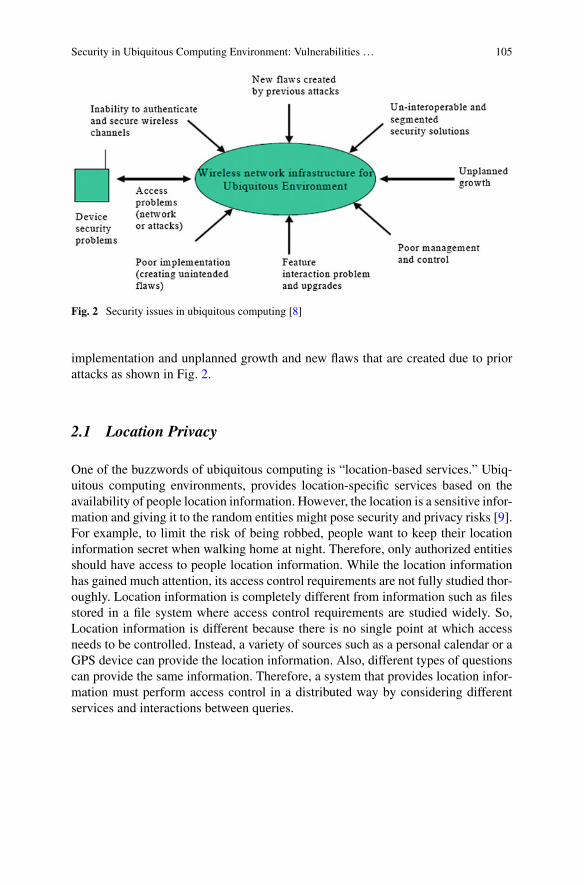
Security in Ubiquitous Computing Environment: Vulnerabilities … 105
Fig. 2 Security issues in ubiquitous computing [8]
implementation and unplanned growth and new flaws that are created due to priorattacks as shown in Fig. 2.
2.1 Location Privacy
One of the buzzwords of ubiquitous computing is “location-based services.” Ubiq-uitous computing environments, provides location-specific services based on theavailability of people location information. However, the location is a sensitive infor-mation and giving it to the random entities might pose security and privacy risks [9].For example, to limit the risk of being robbed, people want to keep their locationinformation secret when walking home at night. Therefore, only authorized entitiesshould have access to people location information. While the location informationhas gained much attention, its access control requirements are not fully studied thor-oughly. Location information is completely different from information such as filesstored in a file system where access control requirements are studied widely. So,Location information is different because there is no single point at which accessneeds to be controlled. Instead, a variety of sources such as a personal calendar or aGPS device can provide the location information. Also, different types of questionscan provide the same information. Therefore, a system that provides location infor-mation must perform access control in a distributed way by considering differentservices and interactions between queries.

106 C. Shoba Bindu and C. Sasikala
Fig. 3 People location system [10]
2.1.1 People Location System
The hierarchical structure of people location system shown in Fig. 3. The nodes inthe graph represent either services or devices and the arrows indicates which serviceinteracts with which other service or device. The location system is the combinationof multiple location services. Each location service uses either a particular technol-ogy for gathering location information or processes location information receivedfrom other location services. Usually, the flow of location information is in reversedirection of a request. To provide efficient scalable and robust services, a locationservice can be implemented either on a single or multiple hosts. These location ser-vices can be divided into two groups, one group includes the services that are awareof the people location information such as People Locator service, Device Locatorservice and Calendar service. The second group has the services, those are aware ofthe location of devices. These services identify the user indirectly by identifying thedevice(s) that the user is carrying with her.
The People Locator service aggregates information received from other services.The Calendar service determines their current location based on people’s appoint-ments. To know the location information of a person the Device Locator servicemaps a query to possibly several queries of her devices and contacts correspondingservices in the second group. In the Fig. 3, this group of services consists of GPSservice and the Wavelan service. The GPS service retrieves the location from GPS

Security in Ubiquitous Computing Environment: Vulnerabilities … 107
enhancedmobile phones. TheWavelan service keeps track of the location of wirelessdevices by identifying their base station
2.1.2 Location Privacy Issues
Location privacy issues arise not just with mobile phones but to a certain extent withany mobile device that communicates with fixed infrastructure while on the move.The primary way to protect location privacy is through access control by giving youthe power to grant or deny access to your location information based on the identityof the requester, as well as other features of the specific query being made. If wefollow this strategy, an application will know that someone is there in that place, andit will provide the service to that person, but no one knows who it is. Even though thisprotection is good, it is not hard to find out which person is present at that locationother than the owner of that location. Sometimes simple heuristics approaches [11]are also used to resolve the ambiguity.
A Countermeasure for the above problem is “mix zone” [12], it is an unobservablespatial region in which we prevent the adversary application from tracking us. Wehope that, whenever we leave the mix zone, the application will be mixed up (i.e.confused us) with someone else. Once again we then take on the role of the adversaryapplication and try to break the anonymity by providing a correlation between thosewho entered into the mix zone with those who came out of it. Some researchersalso developed quantitative measures for location privacy. They allow us to assessthe effect of any privacy protecting countermeasures we may adopt objectively. Forexample, degrading the spatial or temporal resolution of the data provided to theapplications. To ensure a certain level of anonymity for the entities being located,Marco Gruteser et al. [13] proposed an alternative safeguard to degrade the spatialand temporal resolution of the answers from the location server to the applications.
Jackson et al. [14] proposed one of the most effective ways of protecting locationprivacy is to reverse the architecture, that is infrastructure tell the mobile nodeswhere they are (as happens in GPS) instead of having mobile nodes (e.g. tags orcellphones) that transmit their location to the infrastructure. For example, instead ofthe user asking which restaurants are there nearby, the restaurants would broadcastmessages with their location and the type of food they offer, which mobile nodeswould pick up or discard based on a local filter set by the user’s query. Scalabilitycan be achieved by adjusting the size of the broadcast cells (smaller, more localcells to accommodate more broadcasters and more frequent broadcasts). Note thatin this reversed architecture the restaurants simply cannot know who receives theiradvertisements (hence absolute privacy protection), but in the previous case the serverknows and can inform them. It can be a financial incentive against the deploymentof such an architecture.
George Daneziset.al [15] and others have studied the Location privacy problemfrom an interestingly different perspective, with the aim of highlighting how muchusers value their privacy. Their studies use experimental psychology and economicstechniques to extract from each user a quantitative monetary value for one month’s

108 C. Shoba Bindu and C. Sasikala
worth of their location data (median answer: under 50 EUR), then they compare itwith national groups, gender and technical awareness.
2.1.3 Location Policies
Location queries can arise both from people and from services. A query can ask forthe location of a user or the people in or at a geographical location, such as a roomin a building (room query). Based on the two primary queries, it is possible to createmore sophisticated queries or services that provide location-specific information. Toprevent location information from unauthorized entities, we may enforce locationpolicies. Location policies allow an entity to access location information about aperson or the people in a room, only if permitted by that person’s and that room’slocation policy respectively. In this section, we examine some location policies andpresent requirements that need to be provided by the access control mechanism of apeople location system.
User and Random Policies
Corresponding to the two primary queries, there are two types of location policies:user policies and room policies. A user policy specifies who is allowed to get locationinformation about a user. “For example, Bob is allowed to find the location of Alice”.A room policy states who is permitted to find out about the people in a room. “Forexample, Bob is allowed to find out about the people in Alice’s office”. Also, bothuser and room policies should be able to limit information flow in other ways. Webelieve that at least the following properties should be controllable:
Granularity: A policy can restrict the granularity of the returned location informa-tion. For example, a user policy can specify the building in which a queried user ispresent is returned instead of the exact room (e.g., \CMUWeanHall” vs. \CMUWeanHall 8220”). A room policy can state the number of people in a room is returnedinstead of the identity of the person in the room (e.g., \two people” vs. \Alice andBob”).Locations/users: User policies includes a set of locations (e.g., buildings or rooms).If the queried user is at one of the listed locations then only the location system willreturn the location information. For example, Bob is allowed to know about Alice’slocation if she is in her office then only he identifies her location”. Similarly, roompolicies can include a set of users. The answer to a room query will include onlyusers listed in the policy (provided they are in the room).Time intervals: Location policies may be limited to certain time intervals duringwhich only access should be granted. For example, access hours can be restricted toworking hours.
In previous work by Spreitzer et al. [16], users can set the boundaries on roompolicies such as users must specify whether they want to be included in results toroom queries or not. This approach is appropriate for some scenarios only not for

Security in Ubiquitous Computing Environment: Vulnerabilities … 109
all. Some people think that, regardless of the user policies of the users in her room,the owner of a room should always be able to find out who is in her room.
User versus Institutional Policies
Depending on the environment, different entities specify location policies. For someenvironments, a central authority defines policies, whereas for others, users set them.Also, some environments might give both users and a central authority the option tospecify policies. In general, governments and companies probably do not want thelocation of their employees or the people in their buildings to be known to outsiders,whereas this information can be delivered to (some) entities within the organization.In such cases, a central authority would establish the location policies such that noinformation is leaked. For other environments, such as a university or a shoppingmall, the institution behind the environment cares less about where an individual isor who is in a room. For these cases, it should be up to an individual to specify heruser policy. We examine some example environments in more detail in the followingsection.
Transitivity of Access Rights
If Bob is allowed to access Alice’s location information, should he be allowed tosend this access to Carol? If Ed is given the right to know people in his office, shouldhe be allowed to grant this right to Fred? In short, can access rights to locationinformation be transitive? The answer to this question depends on the environment.The policymakers must specify whether they want access rights to be transitive ornot. Even if a user does not allow other users to forward his access rights, he maystill issue queries on their behalf. One way to deal with this problem is to take theaccess right back from the user.
Conflicting Policies
User and room policies can conflict. For example, assume that Alice does not allowBob to locate her, but Carol allows Bob to find people in her office. If Alice is inCarol’s office, should the location system tell Bob about it? There are many ways todealwith this problem:TheLocation system ignores the roompolicywhen answeringa user query. Similarly, it ignores the user policies for a room query. In our example,if you ask people at Carol’s office, Bob sees Alice, but he is not allowed to ask auser query for Alice. The system looks at both policies for any request and returnsinformation only if it is approved by both of them. Thus Bob should not be able to seeAlice being in Carol’s office. The user and room policies are fixed in a synchronizedfashion so that no conflicts arise. For example, Leonhardt and Magee [17] suggestedauthorizing user/room pairs, Alice and Carol’s location policies would thus have tobe rewritten. The efficiency of this approach depends on the environment in whichthe location system is deployed.

110 C. Shoba Bindu and C. Sasikala
2.1.4 Example Environments
In this section, we explore how location policies are specified and applied in twodifferent environments; a hospital and a university environment.
Hospital
Medical information, such as patient information, is protected by a multilateral secu-rity model [18], which protects the flow of information between the compartments.For example, doctors who care about a patient have her medical data, but not everydoctor in the hospital. A similar model is required for location information. Thepatient’s doctor only need to locate her. Also, a patient must be able to allow otherpeople (e.g., her husband) locate her. To meet these requirements, the hospital willset up central authority policies. This can give her the right to include additionalpeople in the user’s policy. Room policies should be established through the centralauthority to protect the privacy of patients. The hospital scenario does not need tosynchronize user and room systems. Patients may be allowed to specify transitiveuser policies, but doctors cannot forward an access right given to them in a userpolicy. Room policies should not be transitive.
University
In the university setting, students and facultymembers derive their customer policies.However, the room procedures were established by a central authority. In an office,the authority office is likely to give the right to establish its roompolicy to thememberof the office. For lecture rooms and hallways, the authority will set the room policiessuch that user and room policies need to be synchronized. That means, when theroom receives a query, the location system asks the user policies in the room/hallbefore the returning their identity. In this scenario, user and room policies are notsynchronized for office. Here, User policies may be transitive but room policies maynot be transitive.
3 RFID Technology
Radio Frequency Identification (RFID) has recently received a lot of attention as agrowing technology in the ubiquitous computing Environment. Because it does notrequire line-of-sight alignment, it identifies the multiple tags simultaneously, and ittags does not destroy the integrity of the original object. It has many benefits likethe low cost of passive RFID tags and the fact that it works without a battery. RFIDsystems [19] have two main components: the RFID tag, which is attached to theobject to be identified and it serves as the data carrier, and the RFID reader, whichcan read from and sometimes even it writes the data to the tag. The tags typicallycontain a microchip that stores data and a coupling element, such as a coiled antennathat is used to communicate via radio frequency communication. The readers usually
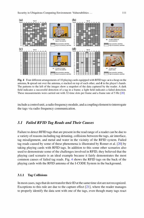
Security in Ubiquitous Computing Environment: Vulnerabilities … 111
Fig. 4 Four different arrangements of 10 playing cards equipped with RFID tags: a in a heap on theantenna, b spread out over the antenna, c stacked on top of each other, and d in the player’s hands.The patterns to the left of the images show a snapshot of the data captured by the reader. A darkfield indicates a successful detection of a tag in a frame; a light field indicates a failed detection.These measurements were carried out with 32-time slots per frame and a frame rate of 5 Hz [20]
include a control unit, a radio frequencymodule, and a coupling element to interrogatethe tags via radio frequency communication.
3.1 Failed RFID Tag Reads and Their Causes
Failure to detect RFID tags that are present in the read range of a reader can be due toa variety of reasons including tag detuning, collisions between the tags, air interface,tag misalignment, and metal and water in the vicinity of the RFID system. Failedtag reads caused by some of these phenomena is illustrated by Romer et al. [20] bytaking playing cards with RFID tags. In addition to this some other scenarios alsoused to demonstrate some of the challenges involved in RFID, they believed that theplaying card scenario is an ideal example because it fairly demonstrates the mostcommon causes of failed tag reads. Fig. 4 shows the RFID tags on the back of theplaying cards with the RFID antenna of the I-CODE System in the background.
3.1.1 Tag Collisions
Inmost cases, tags that donot transfer their IDat the same time slot are not recognized.Exceptions to this rule are due to the capture effect [21], where the reader managesto properly identify the data sent with one of the tags, even though many tags react

112 C. Shoba Bindu and C. Sasikala
at the same time slot. In a stochastic anti-collision algorithm, there is a possibilityfor a tag may not be recognized for a minimum period of a single frame. Obviously,the probability of collisionsincreases with the number of electronic tags present anddecreases with the number of available time slots.
3.1.2 Tag Detuning
In inductively coupled RFID systems the voltage induced in the antenna coil of thetag by the magnetic field is used to power the microchip. Finkenzeller [21] explainedhow the tag manufacturers created a parallel resonance circuit by adding a capaci-tor in parallel to the antenna coil, so that the resonance frequency of the resonancecircuit is tuned to the operating frequency of the RFID system. During the reso-nance, the resonance voltage generated throughout the tuned tag increases as a resultof increasing readability, significantly improving the outgoing bandwidth over fre-quencies. As a resonant application, the tag is, however, vulnerable to environmentaldetuning impacts which can also cause a significant reduction in reading distance.For example, a group of RFID tags that are close to each other, exhibit significantdetuning effects caused by their mutual inductances. Undesirable changes in the tag’sparasitic capacitance and effective inductance can also occur by metal and differentdielectric mediums in the vicinity, e.g. a hand holding the tag. The change in reso-nance frequency away from the operating frequency results in the tag receiving lessenergy from the reader field and hence a decrease in reading distance. Tag detuningdue to other tags that are very close it also cause the low read rates.
3.1.3 Other Sources of Error
Other factors of failed reads include the presence of metal in the tag vicinity envi-ronments because it distorts the magnetic flux, thus weakening the energy couplingto the tag. If the tags are attached to a metal surface, they can often not be detectedat all. Similar to tag detuning, due to the antenna detuning metal in the vicinity ofthe reader antenna results in a read range reduction. Failed reads also caused by themisalignment of the tags with the magnetic field of the reader coil. Maximum powertransfer occurs when the tag coil plane is perpendicular to the magnetic field lines.As the label is rotated concerning the field lines, the coupling is reduced until the tagis no longer identified.
3.2 Security and Privacy
To handle multiple tags reading securely and reliably, some security techniques havebeen developed [22], i.e. SessionConcept, EnhancedSecuredProtocols,GhostReadsImprovements, Dense Readers Conditions and Covered Coding. However, there are

Security in Ubiquitous Computing Environment: Vulnerabilities … 113
still some privacy concerns in both user and application levels. They are also facingsome security loophole in defining and managing the ‘random number’ key thatrequires attention to avoid possible privacy violations or information leakage byeavesdropping on the communication channels.
3.2.1 Fake Tag ID Problems
Generation 2 RFID standards use various implementations to make sure that theincoming tag ID is in fact a valid tag ID rather than noise or glitches(ghost read).Ghost read means, a signal processor interprets noise to be a tag IDand it was a majorobstacle in adopting this valuable technology. One of the drawbacks of Generation1 RFID protocols is ghost read. As a solution to this problem Generation2 RFIDprotocols come up with a ‘Query’ Concept. Communication between tag and readeris definedwith timing constraints to create an illusion of a full duplex link. In practice,the communication is still maintained in a half-duplex mode. The tag does not speakwhen it reads the reader commands, but the time limits respond within a predefinedtime. If the tag fails to respond within the given time, the task will be terminated andthe whole process must start from the beginning.
3.2.2 Password Protection and Effective Randomness
Maintaining a secure link between reader and tag is crucial for preventing datatransmitted over an air interface. In Generation 1:class 1 standards of RFID, an 8-bit password is used to execute the ‘kill’ command to secure the data. This 8-bitpassword is neither secure nor hard to break because of just 256 possible values forthe password. In Generation 1 Class 0, a 24-bit password is used, which providesbetter protection for accessing the data. Generation 2 uses a 32-bit password, so itprovides 4 billion possible values to search for the correct password. Thus, RFIDachieved a level of secure communication that it never before [23].
In Generation 2, along with the password concept, a random number is used toscramble data. The tags will generate and uses a 16-bit Random Number Generator(RNG) throughout the communication session due to this we can ensure that the com-munication link is safe. For example, having a tag of the population up to 10,000, thenthe probability of generating the same sequence at the same time is less than 0.1%.In addition to 32-bit password protection, Generation 2 RFID standards use covercoding while disclosing the data with a random number to randomize the data [24].
3.2.3 Security Problems and Possible Attacks
As a technology with a convergence tendency, the RFID reader can be integratedinto a hand held devices or mobile phones. These Low-cost tags led to widespreadadoption of the technology and deployment on such huge scale, creates new threats

114 C. Shoba Bindu and C. Sasikala
to users and application privacy due to the powerful tracking capability of the tags[25]. All UHF standards provide a security mechanism for reading user memory butany reader can read the tag ID on the fly [26]. A security check should be performedon the tag before the ID is transferred and a mechanism must be defined to identifya credible reader to resolve the privacy issues.
The transmission protocol of tag reader and reader to tag communication definesthe process of exchanging the data and instructions between the reader and the tagin both directions. This protocol works based on the concept of “reader talks first”and means that every tag according to UHF standards will always answer to thereader’s query with its identification (ID) at first. It makes the technology powerfuland an intruder can track the reader tag. The attacker can obtain concrete productinformation associated with the EPC/UID code, it is available on the public network.Even though the current UHF protocols have a ‘kill’ command, the tag is currentlydead and it will be implemented before moving it to the end users’ hands, but thisis not a solution for most applications. Some applications such as vehicle trackingsystem and personal identification systems require tags associated with objects forsecurity purposes. Another security issue related to the tag is specified as, here thecommunication between a tag and a tag reader is using radio frequency, and so anyonecan access the tag and obtain its output. Hence, there is a possibility for an attackerto eavesdrop on the communication channel between tags and readers. Therefore,the authentication scheme used in RFID system must be able to protect the datapassing between the tag and the reader. It means the scheme itself should providesome encryption capability [25].
Generation 2 RFID standards provide a good mechanism to transfer data securelybetween the tag and reader. The exchange of cover-coding was first initiated bya random number request, i.e. RN16, from the Tag. If lower secured plaintext ormechanisms are used, eavesdropping on the communication channel may break theentire security process of the cover-coding. The generation and management of this‘random number’ are important for ensuring the security and integrity of the systembut its size should be reconsidered and the time of command to response should belimited with precise values. So, that the random number is directly proportional tothe time for the command to response. Even though, the random RN16 connectionprovides secure communication link, its 16-bit size still makes it susceptible, asgenerating 65,536 combinations is very easy to find d out those combinations evenwith simple processors. Also, the duration of the command to response time makesit more vulnerable, it means that reader A would start querying the tag but reader B(an intruder) can join in the communication link with a fake random number.
3.2.4 Possible Solutions
To break the cryptosystem, any cryptanalyst must use extremely large amounts ofcomputing recourses and time to analyze the data even if he knows the whole crypt-analytic process. One of the requirements of this cryptosystem is the property ofchanging few parameters that result large change of the whole system. For RFID,

Security in Ubiquitous Computing Environment: Vulnerabilities … 115
the cryptosystem must be easily implemented, so floating-point operations and othercomplicated numerical operations should be avoided.
4 Authentication and Device Pairing
Ubiquitous computing and Peer-to-peer systems involve many principals, but theirnetwork connectivity is irregular and not guaranteed. Traditionalmethods for authen-tication [27, 28], from Kerberos [29] to public-key certificates, are therefore do notwork, because they are based on online connectivity to an authentication or revocationserver. We need new solutions.
Secure transient association
The main application of authentication to intermittently connected networks is asecure transient association. There aremany examples of this paradigm of interactionin applications such asmobile computing, medical equipment, consumer electronics,automatic teller machines, car security systems and weapons systems. To visualizesecure transient association, consider the following scenario: In the ubiquitous com-putingworld, you no longer want to litter your coffee table with some remote controlsfor your TV, DVD, stereo, VCR, curtains, air conditioning, central heating. Instead,you want all of these systems to obey a universal remote control, which for the sakeof argument will be some PDA. Because you no longer buy the remote control withthe appliance, you need to be able to establish an association between the two afterpurchasing the appliance. You want this association to be secure, because you don’twant your neighbor to be able to activate your appliances (whether by accident ormalice). And, if you want to resell your old DVD while keeping your PDA, and youwant to replace a broken PDA without losing control of all your appliances, you alsowant this association to be transient, or revocable.
4.1 Resurrecting Duckling
TheResurrectingDuckling security policymodel Stajano et al. [30]was developed tosolve the above problem and in particular to implement secure transient association:you want to bind a slave device (your new flat screen TV) to a master device (yourcellphone used as a universal remote controller) in a secureway, so that your neighborcan’t turn your TV on and off by mistake (or to annoy you) and so that the stolenTV is useless because it doesn’t respond to any other remote controller; but alsoin a transient way, so that you can resell it without also having to give the buyeryour cellphone. It is based on four principles proposed by Stajano [31]: It describesthe way of establishing asecure transient association between a master and slave.Following four principles define the Resurrecting Duckling.
116 C. Shoba Bindu and C. Sasikala
1. Two State principle. The entity that the policy protects, called the duckling, canbe in one of two states: imprintable or imprinted. In the imprintable state, anyonecan take it over. In the imprinted state, it obeys only its mother duck.
2. Imprinting principle. The transition from imprintable to imprinted, known asimprinting, happens when a principal (mother duck), sends an imprinting key tothe duckling. It must be done using a channel whose confidentiality and integrityare adequately protected (physical contact is recommended). As part of the trans-action, the mother duck must also create an appropriate backup of the imprintingkey.
3. Death principle. The transition from imprinted to imprintable is known as death.It may only occur under a very specific circumstance, defined by the particularvariant of the Resurrecting Duckling policy model. So, one has to chooseoneamong the following.
• The order of the death starts with the mother duck (default).• If a predefined time interval expires then death by old age.• Death after completion of a specific transaction.
4. Assassination principle. The duckling must be built in such a way that it will beuneconomical for an attacker to kill it, i.e. to cause the duckling’s death artificiallyin thecircumstances other than the one prescribed by the Death principle of thepolicy.
Note that the Assassination principle implies that a duckling-compliant devicemust be endowed with some appropriate amount of tamper resistance. The Resur-rectingDuckling policy has very general applicability. It is not patented and thereforeit has been applied in a variety of commercial situations. It has been extended byStajano [32] to allow the mother duck to delegate some or all of its powers to anotherdesignated master.
4.2 Confidentiality
When people think about security issues for ubiquitous computing, they first think ofeavesdropping as a consequence of wireless networking. But this concern is changed:once we have addressed the critical issue of authenticating the principals and shar-ing key material, we have mature and robust symmetric ciphers for protecting acommunications channel’s confidentiality. The actual problems are elsewhere.
Bits per second or Bits per joule?
The size and shape of the typical ubiquitous computing device impose new con-straints. Untethered devices are battery powered, so they cannot use the fastest andmost powerful processors available. To avoid that problem they require very frequentrecharges (as laptop users know all too well). Many ubiquitous computing devicestherefore have processors that are too slow for computationally intensive tasks such
Security in Ubiquitous Computing Environment: Vulnerabilities … 117
as public-key cryptography.It is well known, and one traditional way of dealing withthose processors is to do most of the work as background tasks or as pre compu-tations. But the batteries of small portable devices hold only a small, finite amountof energy; this places a bound on the total amount of computation the devices canperform, rather than on the rate at which they can perform it. This problem is newand more interesting: to evaluate a cipher (or any other algorithm) on a device, themost relevant performance figure is no longer bits per second, but bits per joule.
Biometrics, Coercion, Traffic analysis, and more
While it is straightforward to protect the confidentiality of wireless traffic, it is verydifficult to protect the privacy of the information in the devices. At present, somepeople are concerned about this. Most of the PDAs, for example, which is relativelylikely to be stolen or lost, are not even password protected. Even though those arepassword protected, they do not use encrypted storage. Therefore, those devices aremoderately at the mercy of the effective attacker. It is hardly surprising for bothowner and thief, even the value of the information held in the typical PDA is small.
In the future, however, the ubiquity of computing devices will multiply the oppor-tunities for storage of information about our activities. Our digital butler’s missionis to have the task of identifying and remembering as much as possible about ourhabits and behavior. Finally, the technology infrastructure introduced for one pur-pose has once again misused, think about credit cards being used for purchasing. Itis important to protect the confidentiality of the data held in at least the mother-duckdevices. There are three components to address this problem. The first thing, is tofind techniques that allow users to authenticate their devices, such as a password orbiometric (such as amanuscript signaturewith a pen in PDA) andmuchmore difficultthan it looks. Secondly, protects the keys within the device such as any long-rangekeys that are used to encrypt personal data(user’s profile), and imprining keys of thecontrolled devices. Third, Security Recovery—The problem of recovering from aPDA theft when the device is live or when the thief guesses the owner’s passwordThe fourth is the problem of resistance to the coercion.
Finally, we need to consider metadata protection. Anonymity, traceability, andtraffic analysis are aspects of confidentiality, so far that hasbeen underestimated, butthey will take more prominence in the ubiquitous computing. Encryption makes iteasy to protect a conversation; but the terms when, from, and to are not to mentionthe very fact that a conversation is taking place remain observable. Defending againsttraffic analysis is a difficult problem, and an active research area. From the user’sperspective, it is necessary to support location privacy andmake the task of combininguser’s transactions with each other is difficult, it is necessary at the design stage;otherwise the ubiquitous computing infrastructure will become a tool for ubiquitoussurveillance.

118 C. Shoba Bindu and C. Sasikala
4.3 Integrity
The basic integrity problem is to ensure that messages from one party to another arenot corrupted by amalicious third party. This is similar to confidentiality in that, oncewe know how to do authentication and key distribution, the problem is trivial to solveusing well understood cryptographic mechanisms, such as message authenticationcodes. Authenticating broadcast data is somewhat trickier if we wish to avoid thepower cost of computing a series of digital signatures, but researchers have devisedseveral chaining protocols to tackle this problem. The most serious integrity problemfor ubiquitous computing, therefore, is once again not with the messages in transitbut with the device itself.
Tamper resistance and Tamper evidence
How do I knowwhether a device I am using for communication has been modified oreven replacedwith a duplicate? It is easy to identify this as an authentication problem,and there is a close relationship between integrity and authentication. To address thisissue, Duckling solution may be helpful. However, there is, another aspect to thesolution—physical tamper protection.
The usual assumption underlying authentication is that the network is insecureand it is controlled by the attacker, but that the users involved have the ability tokeep their secrets. Ubiquitous computing takes this assumption and, as it does withso many others, turns it on its head: network attacks are often easier to deal with, butthe attackers destroy many principals in the network. Providing high-level tamperresistance, which makes it impossible for an attacker to access or modify the secretsheld inside a device, which is very expensive and difficult. It is often better to relyon temper resistance instead of tamper evidence stated by Anderson et al. [33].It ensures that tampering attacks and traces of attacks. The main objection to thisstrategy is that it breaks the loop of machine-based verification. A physical seal’sintegrity cannot be verifiable as part of the authentication protocol; instead, it isnecessary to inspect human. Some might see this as a security hole, but it could bean advantage. It means that the responsibility for protection depends on the personrelying on that protection, rather than with some third party whomight have differentmotives. Moreover, managing the protection is also a matter of common sense. Thetwo common reasons for security failure are that the principal responsible for thesecurity is not the principal relying on it, and that technical approaches such aspublic- key certification is difficult to understand and manage. It is somewhat certainfor engineers to assume that they can solve all problems using mechanisms withintheir realm of professional expertise, when other, simpler, mechanisms might bemore robust.

Security in Ubiquitous Computing Environment: Vulnerabilities … 119
4.4 Availability
The traditional attack on the availability of thewireless system is to jam the communi-cation channel. The Ubiquitous systems that rely on short-range RF communicationcan fail in the presence of jamming, but the techniques that deal with it lie outsidesystem design. Once the jammer goes out of the range (or once the police take himaway), the network can start normal operation. And the possibility of a Denial-of-service attack arises from the relationship between security and energy conservation.If a device has limited battery energy then it tries to sleep as much as possible toconserve it, keeping it awake until this energy runs out can be an effective and selec-tive attack. After the battery is flat, the attacker can walkaway, leaving the victimdisabled. We can call this cruel treatment as sleep deprivation violence.
You might think that authentication could prevent such attacks, but this is notalways the case. Authentication lets you distinguish friends from unknowns. But insome applications you cannot refuse to provide services to unknowns. For example,if you are a Web server. The problem for the server is whether to answer queriesfrom unknowns: they might be planninga denial-of service attack, but they might begenuinely interested in the answer. So, Identifying repeat specters is good becausethey can easily fake the source information and they can also corrupt multiple “in-nocent” principals into cooperating in the attack this is called DDOS (distributeddenial-of-service) attack.
When the server has many functions of different importance, they can be pri-oritized and it follows the resources allocation strategy to tighten resources to lessimportant uses. This guarantees a particular level of service to the more importantuses. In fact, it still fails to protect against certain types of attacks, such as those fromauthorized insiders. One approach to this problem is the plutocratic access control:if you got the money to pay you will receive the service. Charging for accessibilitylimits how much to keep clients indiscriminately asking for resources. In fact, if theserver is making a profit in the customer service, denial of service problem is nolonger concern, which means that the server can make more money! If it is not prac-tical to collect the original money, the server can still use the same limited strategyto get some expensive sacrificial ritual in exchange for service. Many researchershave suggested that clients can solve cryptographic puzzles or answer a questionthat is easy for a man but hard for a machine. This approach is more suitable forpeer-to-peer applications, but the former solution is better for ubiquitous computingenvironments.

120 C. Shoba Bindu and C. Sasikala
5 Security Challenges in Ubiquitous Computing:Vulnerabilities, Attacks and Some Defenses
5.1 Vulnerabilities
Network Dynamics: Ubiquitous computing environment has the characteristic forits absence of a fixed infrastructure and a lack of a central server, central authority,and centralized trusted a third party. As mobile devices may join or leave the networkat any given time, it is very important for a network to self-configure.A large number of nodes: The second most commonly addressed challenge resultsfrom the large number of nodes participating in network communications in a ubiqui-tous computing environment. Since some nodes may act selfishly (refuse to forwardpackets to other nodes), maliciously (seek to damage network operations) or showsigns of a dynamic personality (behave strategically in a way that best benefits them).If we do not handle carefully it may lead to a collapse of a whole network. So, intrust computation and management handling bad behavior nodes is a challenge.Resource constraints: In ubiquitous computing environment nodes are heteroge-neous devices that differ in their battery-life, processing power and communicationcapabilities. Due to the devices’ resource constraints, ensuring the availability ofservices and design security mechanisms that rely on complex computations is achallenging task.Authentication-related challenges: The goal of ubiquitous computing is to designenvironments in which people could not be aware of the technologies (embeddedin the environment) surrounding them. Existing authentication mechanisms still donot entirely adaptable with this vision. For example, we have mobile phone lockingmechanisms, such as pattern-drawing or passwords these are necessary to protectthe user’s sensitive data from the unauthorized access. But, they still require deviceowner’s attention to prevent them from their surroundings.Moreover, by havingmoredevices, users may face challenges in remembering all the passwords. As a result,some of the users use the same password for multiple devices or some of them storelist of passwords on their device, so that the user gives an opportunity to the opponentto access the private information.Moreover, some users entirely disable their lockingmechanisms, leaving their devices vulnerable.Other vulnerabilities. Some of the vulnerabilities in the Ubiquitous environmentmay arise due to the lack of knowledge of services, Bluetooth vulnerabilities, frequentchange of a user’s context, and installation of untrusted mobile apps.
5.2 Security Attacks
In this section we discuss Some security attacks in a ubiquitous computing environ-ment (Fig. 5).

Security in Ubiquitous Computing Environment: Vulnerabilities … 121
Fig. 5 Attacks on different nodes [34]
Man-in-the-middle attack: In aUbiquitous computing environment, device authen-tication is important in delivering services. A user must authenticate the artifactmandatorily, while using a secret, i.e., password or PIN code. TheMan-in-the-middleattack occurs when artifacts or users forward the challenges and responses to sim-ulate the existence of other actors. When a client uses his credit card through theterminal, even though there exist proper security protocols, there is a probability ofimpersonation attack. In other words, an attacker can modify the transaction withouthaving the card and without tampering with the terminal. Hence this type of attackcannot be validated in any way without a virtual context in real terminals. This kindof attack allows the impersonation of artifacts and users.Denial Of Service (DOS): This type of attack aims at making the services andresources unavailable to its intended users. For example, by blocking the network,degrading the services, exhausting the device’s resources or providing false trust rat-ings to the nodes participating in communication. So, it is important to take appro-priate steps to find these conditions in advance.Eavesdropping attack: This type of an attack refers to a group of attacks in whicha malicious user monitors conversation to get the knowledge about confidential dataor interferes with the communication channel by modifying messages. One exampleof such an attack is shoulder surfing, in which an adversary observes the contents

122 C. Shoba Bindu and C. Sasikala
on a screen of a mobile device by secretly looking over the user’s shoulder. Anotherexample is snooping, in which an adversary can secretly observe what a person istyping on his/her computer.Cryptanalytic attack: This type of attacks include password cracking attacks,side channel attacks, such as acoustic cryptanalysis key search and electromagneticattacks, and other cryptanalytic attacks, such as preimage, ciphertext, birthday andkey generation attacks.Access network attack: Access network connects the home gateways and outsideservice provider networks. Obviously, if an attacker at the home network connectionpoint, gathers the sensitive data such as financial data, user ID other informationfrom the network packet then the critical information can be exposed.Illegal connection attack: Through the home gateway many household appliancesare connected to multiple networks, usually they are controlled by web-based man-agement but the problem arises when the attacker get this administration information.Once an attacker obtains this information then he can easily attack the rest of net-work. Also, the attackers act as a legitimate internal customer and control the homeappliances. Leakage of information can lead to misuse of it that is not interested inusers.Capturing sensitive data: Electronic sensors are commonly used in the ubiquitousenvironment and because of their poor computational capabilities in the monitoringprocedure, while an attacker can get the sensitive data from the sensor directly byputting a receiver close to it. In these sensors, usually focus is about sensing tasksinstead of cryptographic affairs.Stealing Intermediary device: Usually, an intermediary device will collect the sen-sor data. When the device goes into the hands of an attacker, the device cannot bereused, where it is counted as a breached source for network information to an attack-ing purpose. In many cases, this forms a potential vulnerability because the devicecontains a maintenance interface.Data manipulation: Due to poor computational resources on sensors, they can-not directly authenticate the passing data and they use an intermediate device tostore record logs of the traversing sensor. Even though encryption and decryptiontechniques are used for data authentication, still there is a possibility for data manip-ulation.Impersonating and insiders: In this type of attack devices can be replaced withfake ones by the attacker. So that an impersonating attacker can get the sensitive dataform the network.
5.3 Defenses
Security is the primary issue for the adoption of ubiquitous computing. In this typeof environments and networks, to address the probable security issues, in this sectionwe discuss some solutions.

Security in Ubiquitous Computing Environment: Vulnerabilities … 123
5.3.1 Real-Time Intrusion Detection
The available intrusion detection system (IDS), is not directly deployable into theubiquitous networks due to lack of considerations about flexibility, heterogeneityand resource limitation of ubiquitous networks. As a solution to this problem aservice-oriented and user-centric intrusion detection system (SUIDS) is suggestedwhich record events and logs to imply protection mechanisms on different networkappliances against intrusions. The user-centric approach has been proposed toprovide spontaneous protection against malicious users. Potential distributions arerepresented in the SUDIS behavior of users over a long period, which displays thedesired result and relationship of any actions for a user. In brief, SUIDS includesthe following:
• It accumulates the long-term behaviors of users.• It provides the possible distributions for services.• The normal and current behavior of users is achieved.• It computes the Statistical deviation between established behaviors and currentbehavior.
• It recognizes whether the behavior is an intrusion or not.
5.3.2 RFID Based Authentication Protocol
A radio frequency Identification (RFID) is a microchip that can broadcast a uniqueserial number and other additional data through RF (radio frequency) signals. Thepurpose of RFID is to identify objects remotely by embedding tags into the objects.RFID tags are useful tools in inventory control, manufacturing, supply chain man-agement, etc. In a ubiquitous computing environment, RFID components or RFIDsystems can exist anywhere. Usually, RFID tag ID State holds two values i.e. eitherdynamic or static. If the tag ID State is dynamic means, the tag only communicateswith a fixed back-end database and if it is static means, it can communicate with anyreader in a ubiquitous computing environment. RFID system must be formed to besecure against attacks such as message interception eavesdropping, impersonation,i.e., spoofing and replay and traffic analysis. Even though, RFID technology is well-suited for connecting the physical and virtual world, but before it could become atruly ubiquitous technology it still facing the challenges such as security, privacy,health and safety and creative challenges as well as technical challenges such as inputdata errors and system failures.
5.3.3 Role-Based Access Control
Role Based Access Control system (RBAC), is based on different roles of a personoccurring as part of an organization. In this approach, each role is assigned to a setof permission to hold a place as a hierarchy among other entities. It includes two

124 C. Shoba Bindu and C. Sasikala
types of mappings, which are User Role Assignment (URA) and Role PermissionAssignment (RPA) both is updated individually. Users can extend the URA withoutchanging RPA by providing a predefined role to the new users. And also RPA assignsacceptable behaviors that are restricted to the user. The purpose of RBAC is that URAand PRA vary with less frequency than the permission of individual users. It has beenadaptable for use in ubiquitous computing environments. In brief, RBAC includesthe following:
• It lists the set of privileges related the user role.• The normal action of the user is obtained.• Privileges under role are controlled for allowance.• If the user role is in the acceptable situation, then the user is authenticated.
5.3.4 Information Leakage
Because of the sensitive information particularly in expensive products, and concern-ing of users due to their information security, this matter is critical to solving. Onthe other hand, RFID systems only response with distinguished emitting signals to aquery which is related to neighborhood domain. Leakage of information may occurwithout knowing to the users. Information leakage is more problematic by insiderswhen the property’s value is high and if the leakage happens in information sharingand information accessibility the problem is more serious. Hence, it is important todevelop security technology, which controls the leakage more and more at any timeby enabling staff inside the company to access inside information at any time in anyplace supporting high work efficiency.
5.3.5 Cryptographic Protocols
With the proliferation of small and resource-constrained devices, lightweightcryptography has appeared as a new branch of cryptography which incurs lessercomputational overhead. Protocols in ubiquitous computing mostly rely on threetypes of cryptographic algorithms asymmetric and asymmetric, while a majority ofresearchers focusing on a combination of both (hybrid approaches) to design lightweight protocols.
5.3.6 Trust-Based Computation and Management
In a ubiquitous computing network, mobile nodes can engage themselves in a spon-taneous interaction with other nodes. With the number of growing mobile devicesparticipating as network nodes, it becomes a challenge to ensure its behavior prop-erly. The importance of designing efficient trust models for such dynamic interactionand fast-changing network topologies has gained prominence over the past decade.

Security in Ubiquitous Computing Environment: Vulnerabilities … 125
Trust models rely on the trust values that are assigned or derived based on the node’sbehavior. Some models assume direct interaction with the newly arrived node toassess its behavior, while other models use recommendations from previous nodesthose interacted with the newcomer node to evaluate its behavior. If a node is pre-dicted to be well-behaved, it can communicate with other nodes on the network.Malicious nodes are excluded from the network. It is important to ensure dynamicsin trust computation by monitoring a node’s actions and recomputing the assignedtrust values since nodes may become non-cooperative over time.
5.3.7 Traceability
An opponent can record the transmitted message from a response to a target tagand establish a link between them. Through this link, the user’s location informationcan be traced by an opponent. In the authentication situations the following must beconsidered:
• Read the RFID-tag from the product• Transform of the RFID-tag for the database server• Check for the authenticity of the RFID-tag• Compare the RFID-tag with an organization that indicates authentication.
5.3.8 Biometrics
It implicates good properties to provide consistent and automated mechanisms fordetermining and confirming identity while, being less prominent. Finger print recog-nition, or face recognition techniques are faster than entering secure passwords andthey do not require special devices like PDA. But, the biometric authentication tech-niques are heavily dependent on hardware in terms of accuracy and consistency. Inany biometric technique, the principal concern is the biometric template and design-ing these elements represent unique personal information. Unfortunately, it is notpossible to change or replace the biometric characteristics—they are an inherent partof the person unlike the other forms of authentication (such as secret knowledge ortokens, which can be simply changed if lost or stolen). Therefore, once lost or stolen,they are compromised and can no longer be used reliably. Even though, biomet-ric authentication techniques still do not have a good and secure method of storingbiometric properties, they preserve anonymity while providing enough flexibility toaccommodate partial matches and reduce a suitable confidence level.
Conclusion: Security is one of themost prominent issues in ubiquitous computing. Itenables communication devices to traverse openly, anywhere at any time. Therefore,the modern computing networks have become increasingly ubiquitous. When ser-vices are provided easily for all various networks and their users, the major concernis about the security. In this chapter we discussed the security issues in a ubiquitous

126 C. Shoba Bindu and C. Sasikala
computing environment such as Location privacy, vulnerability, attacks and we alsoexplained some defenses concerning attacks.
References
1. DragoniN,Massacci F,Walter T, Schaefer C (2009)What the heck is this application doing?—asecurity-by-contract architecture for pervasive services. Comput Secur 28(7):566–577
2. Pietro RD, Mancini LV (2003) \Security and privacy issues of handheld and wearable wirelessdevices. ACM Commun 46(9):74–79
3. Yau SS, Huang D, Gong H, Yao Y (2006) Support for situation awareness in trustworthyubiquitous computing application software. J Softw Pract Eng 36(9):893–921
4. Weiser Mark (1991) The Computer for the 21st century. Sci Am 265(3):66–755. Weiser Mark (1994) The World is not a desktop. Interactions 1(1):7–86. KangYB, PisanY (2006)A survey ofmajor challenges and future directions for next generation
pervasive computing. In: Proceedings of the 21st international symposium on computer andinformation sciences, pp 755–764
7. Poslad S (2009) Ubiquitous computing: smart devices, environments and interactions. Wiley-Blackwell
8. Varshney U, Vetter R (2002) Mobile commerce: framework, applications, and networkingsupport. ACM/Kluwer Journal onMobile Networks and Applications (MONET) 7(3):185–198
9. Spreitzer M, Theimer M (1993) Providing location information in a ubiquitous computingenvironment. In: Proceedings of SIGOPS ’93, Dec 1993, pp 270–283
10. Garlan D, Siewiorek D, Smailagic A, Steenkiste P (2002) Project aura: towards distraction-freepervasive computing. IEEE Pervasive Comput 1:22–31
11. Beresford A, Stajano F (2003) Location privacy in pervasive computing. IEEE Pervasive Com-put 2(1):46–55
12. Chaum DL (1981) Untraceable electronic mail, return addresses, and digital pseudonyms.Commun ACM 24(2):84–88, http://doi.acm.org/10.1145/358549.358563
13. Gruteser M, Grunwald D (2003) Anonymous usage of location-based services through spa-tial and temporal Cloaking. In: Proceedings of MobiSys 2003, the Usenix Association, SanFrancisco, CA, USA, pp 31–42
14. Jackson IW (1998) Who goes here? confidentiality of location through anonymity. PhD thesis,University of Cambridge
15. Danezis G, Lewis S, Anderson R (2005) How much is location privacy worth? In: Proceedingsof Workshop on Economics of Information Security (WEIS), http://infosecon.net/workshop/pdf/locationprivacy.pdf
16. Spreitzer M, Theimer M (1993) Providing location information in a ubiquitous computingenvironment. In: Proceedings of SIGOPS ’93, pp 270–283
17. Leonhardt U, Magee J (1998) Security considerations for a distributed location service. J NetwSyst Manage 6:51–70
18. Rannenberg K, PfitzmannA,Muller G (1999)Multilateral security in communications, chapterIT security and multilateral security, Addison-Wesley-Longman, pp 21–29
19. Finkenzeller K (2000) RFID handbook: radio-frequency identification fundamentals and appli-cations. Wiley
20. Romer K, Domnitcheva S (2002) Smart playing cards: a ubiquitous computing game. Journalfor Personal and Ubiquitous Computing (PUC) 6
21. Wieselthier JE, Ephremides A, Michaels LA (1989) An exact analysis and performance eval-uation of framed aloha with capture. IEEE Trans Commun 37(2):125–137
22. Sarma SE, Weis SA, Engels DW (2002) RFID systems and security and privacy implications.In:Workshop on Cryptographic Hardware and Embedded Systems, Lecture Notes in ComputerScience, pp 454–470

Security in Ubiquitous Computing Environment: Vulnerabilities … 127
23. Roberti M (2005) Understanding the EPC Gen 2 Protocol. RFID journal special report, Mar2005
24. EPCglobal Inc. (2005) EPC™Radio-Frequency Identity Protocols Class-1 Generation-2 UHFRFID, Jan 2005
25. Luo Z, Chan T, Li JS (2005) A lightweight mutual authentication protocol for RFID networks.In: IEEE international conference on e-business engineering, Oct 2005, pp 620–625
26. Garfinkel SL, Juels A, Pappu R (2005) RFID privacy: an overview of problems and proposedsolutions. IEEE Secur Priv 3(3), pp 34–43, May–June 2005
27. Needham RM, Schroeder MD (1978) Using encryption for authentication in large networks ofcomputers. Commun ACM 21(12):993–999
28. Norman DA (1998) The invisible computer: why good products can fail, the personal computeris so complex, and information appliances are the solution. MIT Press
29. Kohl J, Neuman C (1993) Thekerberos network authentication service (v5). RFC 1510, IETF,http://www.ietf.org/rfc/rfc1510.txt
30. Stajano F, Anderson R (1999) The resurrecting duckling: Security issues in ad-hoc wirelessnetworks. In: Christianson B, Crispo B, Malcolm JA, RoeM (eds) Proceedings of the 7th inter-national workshop security protocols, Lecture Notes in Computer Science, vol 1796, Springer,pp 172–182
31. Stajano F (2002) Security for ubiquitous computing. Wiley, http://www.cl.cam.ac.uk/~fms27/secubicomp/
32. Stajano F (2001) The resurrecting duckling—what next? In: ChristiansonB,CrispoB,MalcolmJA, Roe M (eds) Proceedings of the 7th international workshop security protocols, LectureNotes in Computer Science, vol 2133, Springer-Verlag, pp 204–214
33. Anderson RJ, Kuhn MG (1996) Tamper resistance—a cautionary note. In: Proceedings of thesecond usenix workshop on electronic commerce, Usenix Association, Berkeley, pp 1–11
34. Sharif A, Khosravi M, Shah A (2013) Security attacks and solutions on ubiquitous computingnetworks. International Journal of Engineering and Innovative Technology (IJEIT) 3(4), Oct2013, ISSN:2277–3754