Embed Size (px)
Citation preview

Institut für Angewandte Physik
LINAC AG
MYRRHA Accelerator 1st International Design Review, Nov. 12-13, 2012 1
MYRRHA Injector Design
Horst Klein
Dominik Mäder, Holger Podlech, Ulrich Ratzinger,
Alwin Schempp, Rudolf Tiede, Markus Vossberg, Chuan Zhang
Institute for Applied Physics, Goethe-University Frankfurt am Main

Institut für Angewandte Physik
LINAC AG
MYRRHA Accelerator 1st International Design Review, Nov. 12-13, 2012 2
Driver Linac Layout
Institut für Angewandte Physik
LINAC AG
MYRRHA Accelerator 1st International Design Review, Nov. 12-13, 2012 3
Injector Part
C. Zhang, H. Klein, H. Podlech et al., LINAC 2012, THPB005
0.03 MeV
Institut für Angewandte Physik
LINAC AG
MYRRHA Accelerator 1st International Design Review, Nov. 12-13, 2012 4
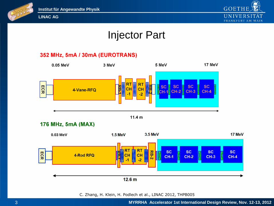
ECR Ion Source
• Pantechnik Monogan M-1000
• 20 mA capable
• 45 kV capable
• emittance measurement
(Allison scanner) included
• delivery and installation I-2013
εrms: 0.1 - 0.15 π mm mrad
(requested)
Courtesy of D. Vandeplassche
Institut für Angewandte Physik
LINAC AG
MYRRHA Accelerator 1st International Design Review, Nov. 12-13, 2012 5
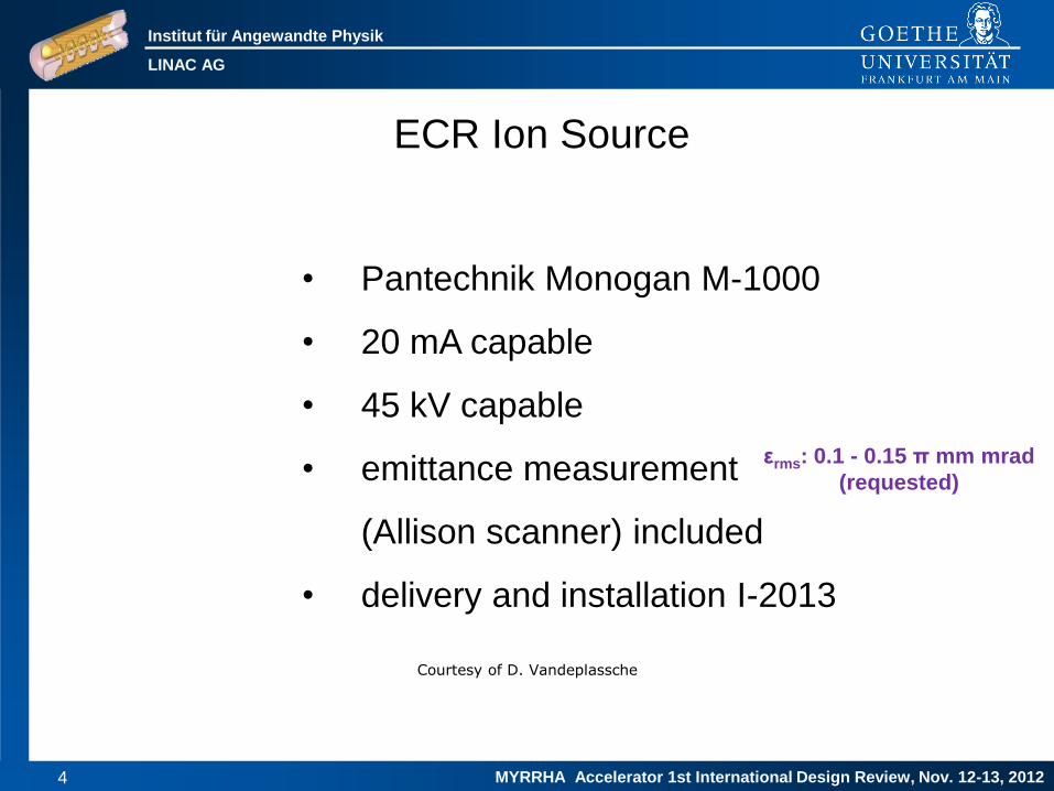
LEBT Design & Space-Charge Compensation
0.12 T 0.15 T
Ltotal=2.3m
Courtesy of
J.-L. Biarrotte
Institut für Angewandte Physik
LINAC AG
MYRRHA Accelerator 1st International Design Review, Nov. 12-13, 2012 6
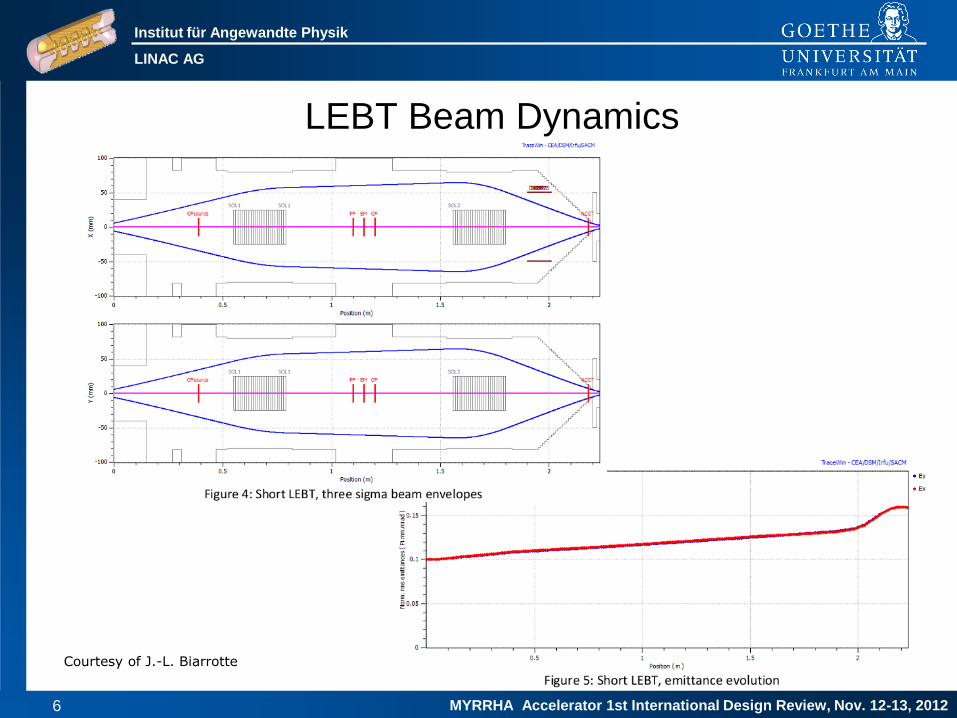
LEBT Beam Dynamics
Courtesy of J.-L. Biarrotte

Institut für Angewandte Physik
LINAC AG
MYRRHA Accelerator 1st International Design Review, Nov. 12-13, 2012 7
Injector Part
300kW 41kW 47kW ∑=388kW
94kW 16kW 20kW ∑=130kW
ε=0.2 0.22 0.27π mm mrad
C. Zhang, H. Klein, H. Podlech et al., LINAC 2012, THPB005
0.03 MeV

Institut für Angewandte Physik
LINAC AG
MYRRHA Accelerator 1st International Design Review, Nov. 12-13, 2012 8
4-Vane Structure vs. 4-Rod Structure
Mini Vanes
Institut für Angewandte Physik
LINAC AG
MYRRHA Accelerator 1st International Design Review, Nov. 12-13, 2012 9
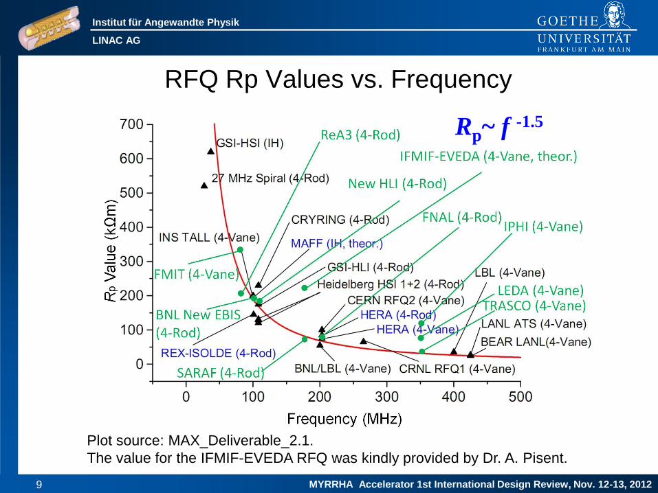
RFQ Rp Values vs. Frequency
Rp~ f -1.5
Plot source: MAX_Deliverable_2.1.
The value for the IFMIF-EVEDA RFQ was kindly provided by Dr. A. Pisent.
Institut für Angewandte Physik
LINAC AG
MYRRHA Accelerator 1st International Design Review, Nov. 12-13, 2012 10
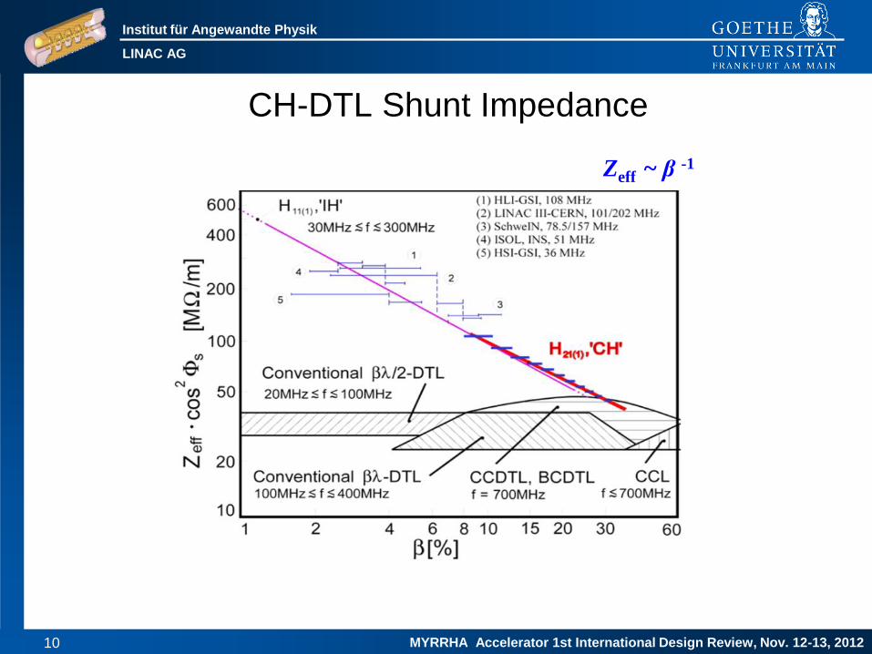
CH-DTL Shunt Impedance
Zeff ~ β -1

Institut für Angewandte Physik
LINAC AG
MYRRHA Accelerator 1st International Design Review, Nov. 12-13, 2012 11
Why change the frequency from 352MHz
(EUROTRANS) to 176MHz (MAX)?
For all RFQs: the value of Rp=U2/P is increasing by a factor of ~2.5.
Nevertheless the best choice for f≥300MHz is the 4-vane RFQ. The
low frequencies allow the use of the simple 4-rod RFQ, which has
some advantages: the chain of /4 resonators are strongly coupled,
resulting in a stable longitudinal field, so for example only 2 plungers
are needed for a 4m long RFQ. The outer conductor plays a small
role, so it can have a lid, which allows a direct access to the
electrodes for mounting and repair, increasing the reliability and
availability. It has a compact size, low weight, is relatively easy to
manufacture at low cost. And it can be built in a rather short time. Its
application allows to reduce the injection energy into the CH-linac to
1.5MeV, which reduces the overall power consumption considerably.
Institut für Angewandte Physik
LINAC AG
MYRRHA Accelerator 1st International Design Review, Nov. 12-13, 2012 12
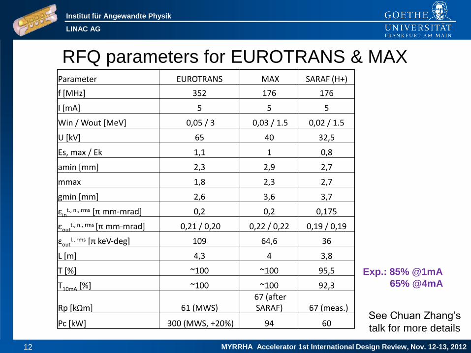
Parameter EUROTRANS MAX SARAF (H+)
f [MHz] 352 176 176
I [mA] 5 5 5
Win / Wout [MeV] 0,05 / 3 0,03 / 1.5 0,02 / 1.5
U [kV] 65 40 32,5
Es, max / Ek 1,1 1 0,8
amin [mm] 2,3 2,9 2,7
mmax 1,8 2,3 2,7
gmin [mm] 2,6 3,6 3,7
εint., n., rms [π mm‐mrad] 0,2 0,2 0,175
εoutt., n., rms [π mm‐mrad] 0,21 / 0,20 0,22 / 0,22 0,19 / 0,19
εoutl., rms [π keV‐deg] 109 64,6 36
L [m] 4,3 4 3,8
T [%] ~100 ~100 95,5
T10mA [%] ~100 ~100 92,3
Rp [kΩm] 61 (MWS) 67 (after SARAF) 67 (meas.)
Pc [kW] 300 (MWS, +20%) 94 60
RFQ parameters for EUROTRANS & MAX
See Chuan Zhang’s
talk for more details
Exp.: 85% @1mA
65% @4mA

Institut für Angewandte Physik
LINAC AG
MYRRHA Accelerator 1st International Design Review, Nov. 12-13, 2012 13
Several improvements of the RFQ were necessary to
fulfill the MYRRHA requirements (CW operation,
high reliability and availability)
Complete new design of the RFQ structure (e.g. outer conductor,
stems inserted from bottom) by A. Schempp, Lit.: Overview of Recent
RFQ Projects, Proc. LINAC08, MO302, p.41-43. Together with A.
Bechtold (NTG): New methods for production of stems and
electrodes, higher precision (~15m), an improved cooling system,
new techniques for production of cooling channels (milling and
galvanic copper plating, new rf contacts at the tuning plates, better
alignment).
Institut für Angewandte Physik
LINAC AG
MYRRHA Accelerator 1st International Design Review, Nov. 12-13, 2012 14
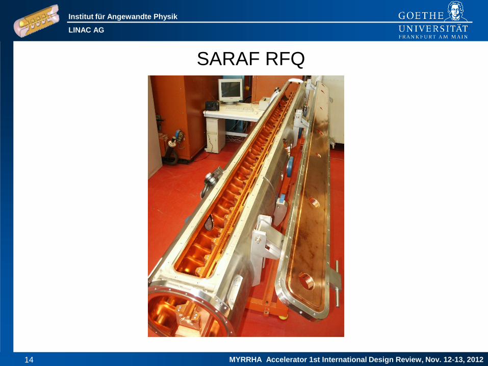
SARAF RFQ
Institut für Angewandte Physik
LINAC AG
MYRRHA Accelerator 1st International Design Review, Nov. 12-13, 2012 15
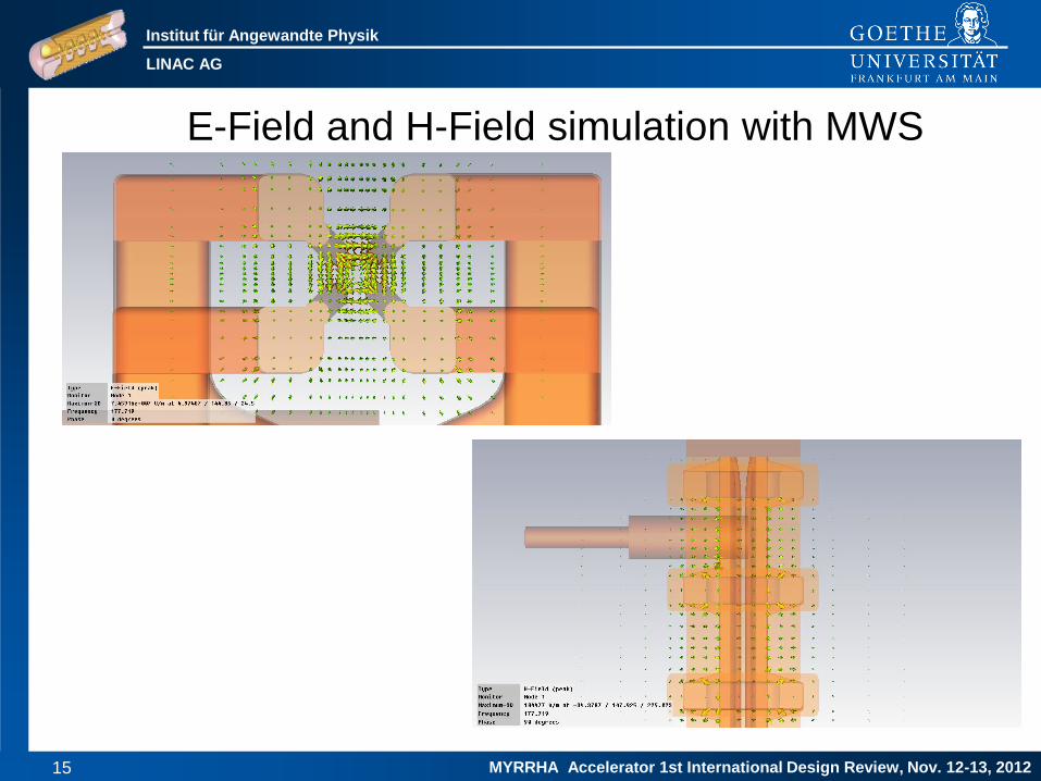
E-Field and H-Field simulation with MWS

Institut für Angewandte Physik
LINAC AG
MYRRHA Accelerator 1st International Design Review, Nov. 12-13, 2012 16
RFQ Test Section
Length [mm] 532 (432)
Stem distance [mm] 97
Electrodelength [mm] 342
Beam axis [mm] 145
Frequency [MHz] 176
Quality factor 4900
Tuner (diameter) [mm] 40
45 mm 40 mm 30 mm

Institut für Angewandte Physik
LINAC AG
MYRRHA Accelerator 1st International Design Review, Nov. 12-13, 2012 17
Surface Current
Power: 25 kW/m (design)
Power Test RFQ: 12 kW
Thermal losses: 8 kW
(simulated)

Institut für Angewandte Physik
LINAC AG
MYRRHA Accelerator 1st International Design Review, Nov. 12-13, 2012 18
Stems with the new coolingsystem design (NTG)
Because of the thermal
losses, a very good
water cooling system is
required to hold the
frequency steady during
cw-operation.The new
cooling system of the
stem is split into two
paths. Booth sides of
the stems are well
cooled. In addition the
stems have a channel
for the electrode
cooling.

Institut für Angewandte Physik
LINAC AG
MYRRHA Accelerator 1st International Design Review, Nov. 12-13, 2012 19
Electrodes with the new coolingsystem design (NTG)

Institut für Angewandte Physik
LINAC AG
MYRRHA Accelerator 1st International Design Review, Nov. 12-13, 2012 20
Silverplated Tuningplates
Institut für Angewandte Physik
LINAC AG
MYRRHA Accelerator 1st International Design Review, Nov. 12-13, 2012 21
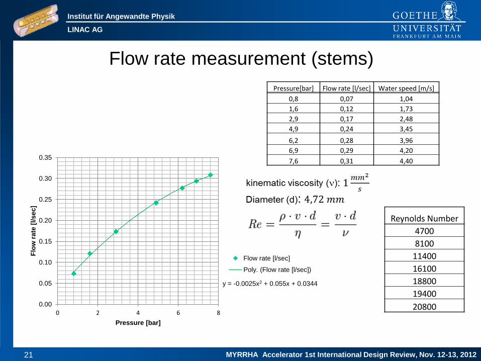
Flow rate measurement (stems)
y = -0.0025x2 + 0.055x + 0.0344
0.00
0.05
0.10
0.15
0.20
0.25
0.30
0.35
0 2 4 6 8
Flo
w r
ate
[l/sec]
Pressure [bar]
Flow rate [l/sec]
Poly. (Flow rate [l/sec])
Reynolds Number
4700
8100
11400
16100
18800
19400
20800
Pressure[bar] Flow rate [l/sec] Water speed [m/s]
0,8 0,07 1,04
1,6 0,12 1,73
2,9 0,17 2,48
4,9 0,24 3,45
6,2 0,28 3,96
6,9 0,29 4,20
7,6 0,31 4,40
Institut für Angewandte Physik
LINAC AG
MYRRHA Accelerator 1st International Design Review, Nov. 12-13, 2012 22
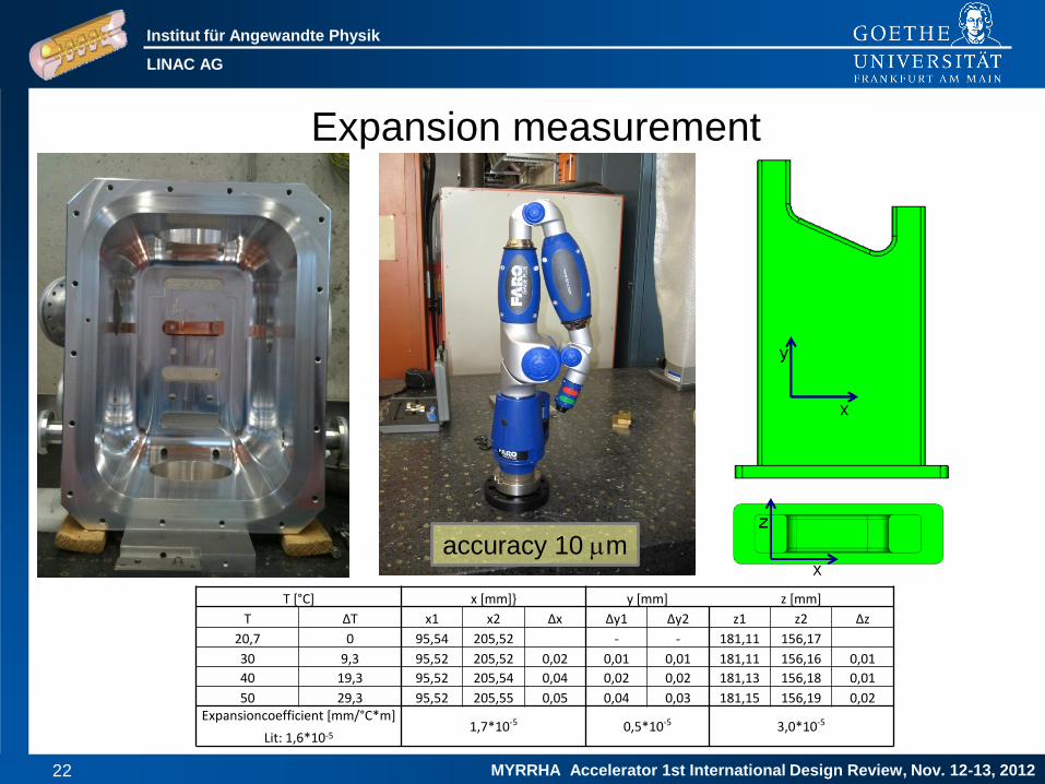
Expansion measurement
accuracy 10 m
T [°C] x [mm]} y [mm] z [mm]
T ΔT x1 x2 Δx Δy1 Δy2 z1 z2 Δz
20,7 0 95,54 205,52 109,98 - - 181,11 156,17 24,94
30 9,3 95,52 205,52 0,02 0,01 0,01 181,11 156,16 0,01
40 19,3 95,52 205,54 0,04 0,02 0,02 181,13 156,18 0,01
50 29,3 95,52 205,55 0,05 0,04 0,03 181,15 156,19 0,02 Expansioncoefficient [mm/°C*m]
1,7*10-5 0,5*10-5 3,0*10-5 Lit: 1,6*10-5

Institut für Angewandte Physik
LINAC AG
MYRRHA Accelerator 1st International Design Review, Nov. 12-13, 2012 23
Pressure [bar] Coolingwater in [°C] Coolingwater out [°C] Copper Temperature [°C] Thermal bath [°C]
1,7 19 21,5 27,6 70
3 19 20,65 26 70
5,2 19 20,2 24,5 70
6,5 19 20 23,8 70
7,6 18,7 19,65 23,5 70
Thermal measurement
dm/dt [l/sec]] c [J/(kg*K]] DT [°C] P [W]
0,12 4182 2,5 1261
0,17 4182 1,65 1220
0,25 4182 1,2 1268
0,28 4182 1 1197
0,30 4182 0,95 1223
Power losses for a single Stem: 1350 W
→ DTK = 1,05 °C (for 7,6 bar)
Institut für Angewandte Physik
LINAC AG
MYRRHA Accelerator 1st International Design Review, Nov. 12-13, 2012 24
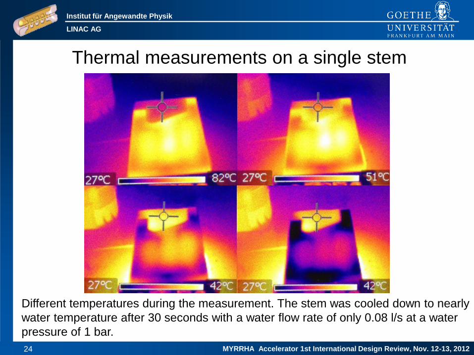
Thermal measurements on a single stem
Different temperatures during the measurement. The stem was cooled down to nearly
water temperature after 30 seconds with a water flow rate of only 0.08 l/s at a water
pressure of 1 bar.

Institut für Angewandte Physik
LINAC AG
MYRRHA Accelerator 1st International Design Review, Nov. 12-13, 2012 25
Thermal simulation with cooling (25 kW/m)
Institut für Angewandte Physik
LINAC AG
MYRRHA Accelerator 1st International Design Review, Nov. 12-13, 2012 26

Institut für Angewandte Physik
LINAC AG
MYRRHA Accelerator 1st International Design Review, Nov. 12-13, 2012 27

Institut für Angewandte Physik
LINAC AG
MYRRHA Accelerator 1st International Design Review, Nov. 12-13, 2012 28

Institut für Angewandte Physik
LINAC AG
MYRRHA Accelerator 1st International Design Review, Nov. 12-13, 2012 29

Institut für Angewandte Physik
LINAC AG
MYRRHA Accelerator 1st International Design Review, Nov. 12-13, 2012 30

Institut für Angewandte Physik
LINAC AG
MYRRHA Accelerator 1st International Design Review, Nov. 12-13, 2012 31

Institut für Angewandte Physik
LINAC AG
MYRRHA Accelerator 1st International Design Review, Nov. 12-13, 2012 32

Institut für Angewandte Physik
LINAC AG
MYRRHA Accelerator 1st International Design Review, Nov. 12-13, 2012 33
Injector Part
300kW 41kW 47kW ∑=388kW
94kW 16kW 20kW ∑=130kW
ε=0.2 0.22 0.27π mm mrad
C. Zhang, H. Klein, H. Podlech et al., LINAC 2012, THPB005
0.03 MeV

Institut für Angewandte Physik
LINAC AG
MYRRHA Accelerator 1st International Design Review, Nov. 12-13, 2012 34
CH-DTL parameters for EUROTRANS & MAX
EUROTRANS MAX
Veff Lcell ßavg Ea Veff Lcell ßavg Ea
[MV] [m] [MV/m] [MV] [m] [MV/m]
RB1 0.19 0.07 0.08 2.79 0.15 0.10 0.06 1.56
RT1 1.16 0.40 0.09 2.91 1.03 0.54 0.06 1.92
RT2 1.30 0.50 0.10 2.59 1.14 0.66 0.08 1.74
RB2 0.47 0.09 0.10 5.23 0.53 0.36 0.09 1.44
SC1 2.54 0.63 0.11 4.00 3.50 0.86 0.10 4.06
SC2 3.22 0.81 0.14 3.99 3.98 0.99 0.13 4.00
SC3 3.74 0.94 0.16 3.99 4.18 1.07 0.16 3.91
SC4 3.76 1.05 0.18 3.57 4.09 1.07 0.18 3.83
See Holger Podlech’s talk for more details
Institut für Angewandte Physik
LINAC AG
MYRRHA Accelerator 1st International Design Review, Nov. 12-13, 2012 35
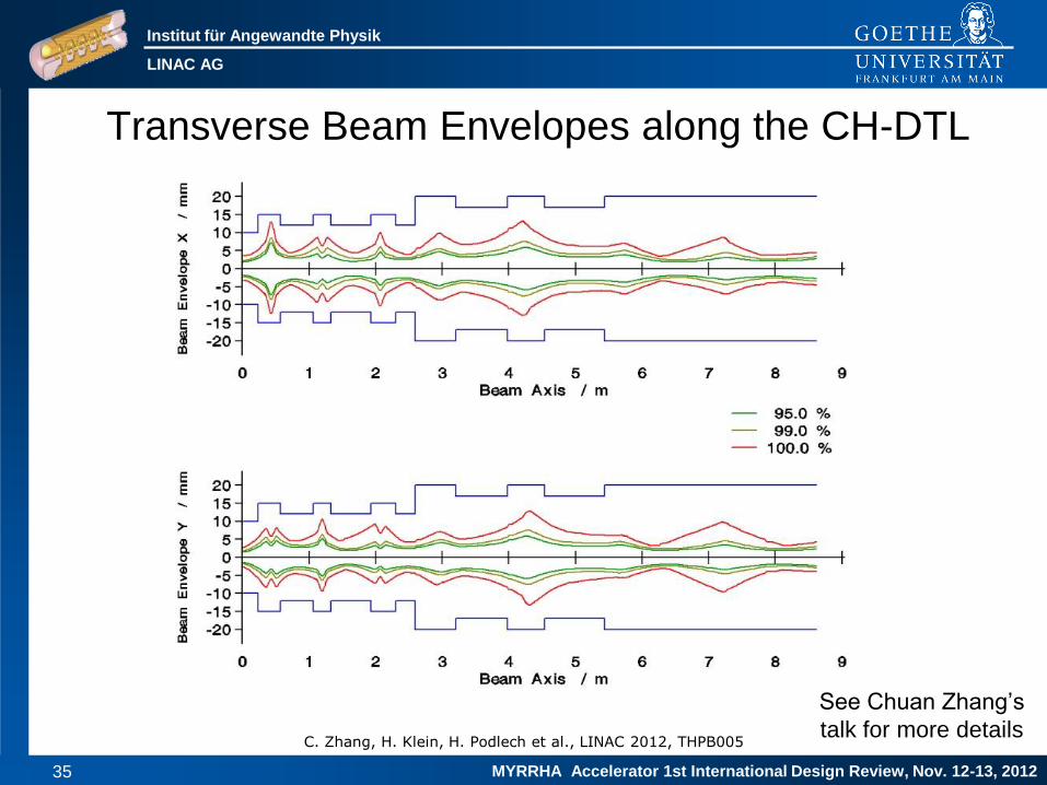
Transverse Beam Envelopes along the CH-DTL
C. Zhang, H. Klein, H. Podlech et al., LINAC 2012, THPB005
See Chuan Zhang’s
talk for more details

Institut für Angewandte Physik
LINAC AG
MYRRHA Accelerator 1st International Design Review, Nov. 12-13, 2012 36
Room Temperature CH-Cavities
Prototype cavity presently under
construction
RF test up to 40 kW/m
Parameter CH-1 CH-2 Unit
Frequency 176 176 MHz
Duty factor 100 100 %
Zeff 113 100 MW/m
Ueff 1.03 1.14 MV
Pc 16.5 18.5 kW
CH-1

Institut für Angewandte Physik
LINAC AG
MYRRHA Accelerator 1st International Design Review, Nov. 12-13, 2012 37
Test Results SC CH-Prototype
MYRRHA
Institut für Angewandte Physik
LINAC AG
MYRRHA Accelerator 1st International Design Review, Nov. 12-13, 2012 38
CH3
CH4 CH5 CH6
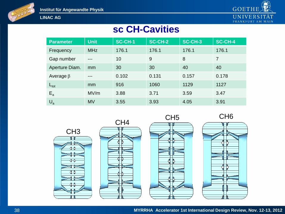
sc CH-Cavities Parameter Unit SC-CH-1 SC-CH-2 SC-CH-3 SC-CH-4
Frequency MHz 176.1 176.1 176.1 176.1
Gap number --- 10 9 8 7
Aperture Diam. mm 30 30 40 40
Average b --- 0.102 0.131 0.157 0.178
Ltot mm 916 1060 1129 1127
Ea MV/m 3.88 3.71 3.59 3.47
Ua MV 3.55 3.93 4.05 3.91

Institut für Angewandte Physik
LINAC AG
MYRRHA Accelerator 1st International Design Review, Nov. 12-13, 2012 39
Bellow Tuner Static Tuners
Helium Vessel Coupler Flanges
325 MHz CH-Cavity

Institut für Angewandte Physik
LINAC AG
MYRRHA Accelerator 1st International Design Review, Nov. 12-13, 2012 40
Parameter Unit CH-1
Beta 0.059
Frequency MHz 216.816
Gap number 15
Total length mm 687
Cavity diameter mm 409
Cell length mm 40.82
Aperture mm 20
Ua MV 3.369
Energy gain MeV 2.97
Accelerating gradient MV/ m 5.1
Ep/ Ea 6.4
Bp/ Ea mT/ (MV/m) 5.4
R/ Q Ω 3320
Static tuner 9
Dynamic bellow tuner 3
Main parameters of the 217 MHz CH-structure
Construction has started
3D-view of the 217 MHz cavity with helium vessel, without tuners
Helium vessel
Coupler flange Pickup flange
Inclined
end stem
Tuner flange
Preparation
flange
217 MHz CH-Cavity


![[email protected] : an Application of the MYRRHA Accelerator for Nuclear](https://img.pdfslide.us/doc/110x75/61fb2f0d2e268c58cd5b2553/emailprotected-an-application-of-the-myrrha-accelerator-for-nuclear.jpg)