Embed Size (px)
Citation preview
1
ISOL@MYRRHA
‘An On-Line Isotope Separator coupled to the MYRHHA Proton Accelerator’
Editors:
Dieter Pauwels (K.U.Leuven) and Paul Schuurmans (SCK•CEN)

2
This document is a work in progress on the technical and scientific aspects of
ISOL@MYRRHA and is based on ideas presented during the ‘Nuclear Physics Research at the MYRRHA Accelerator’
BriX workshop 2008 in Mol (Belgium) (http://iks32.fys.kuleuven.be/wiki/brix/index.php/Workshops) by:
Hamid Aït Abderrahim (B)
Bertram Blank (France) Yorick Blumenfeld (France) Marik Dombsky (Canada) Yacine Kadi (Switzerland)
Hans-Jürgen Kluge (Germany) Ulli Köster (France)
Jacques Lettry (Switzerland), Alex Mueller (France)
Valentina Ricciardi (Germany) Danas Ridikas (France)
Karsten Riisager (Switzerland) Zaher Salman (Canada)
Dorothea Schumann (Switzerland) Nathal Severijns (Belgium)
Ulrich Wahl (Portugal) Hans Wilschut (Netherlands)
It includes contributions from:
Mark Huyse, Gerda Neyens, Dieter Pauwels, Riccardo Raabe, Nathal Severijns, Kristiaan Temst, Piet Van Duppen, André Vantomme
K.U.Leuven, Belgium
Hamid Aït Abderrahim, Peter Baeten, Didier De Bruyn, Jan Heyse, Lucia Popescu, Paul Schuurmans, Dirk Vandeplassche, Jan Wagemans
SCK•CEN, Belgium
Daniel Baye, Pierre Descouvemont, Paul-Henri Heenen, Jean-Marc Sparenberg U.L.B. (Brussels), Belgium
Kris Heyde and Cyril Wagemans
U.Gent, Belgium
November 2009 (version 1.0)

3
Contents 0B0BList of Abbreviations .....................................................................................................5 1 Preamble ................................................................................................................6 2 Introduction............................................................................................................7 3 3B3BThe MYRRHA project...........................................................................................9
3.1 8B10BIntroduction....................................................................................................9 3.2 9B11BMajor MYRRHA design characteristics ......................................................10 3.3 10B12BApplications catalogue of MYRRHA..........................................................11 3.4 11B13BThe implementation plan of MYRRHA ......................................................11
4 4B4BISOL@MYRRHA: technical description ............................................................13 4.1 12B14BIntroduction..................................................................................................13 4.2 13B15BBeam splitter ................................................................................................13 4.3 14B16BSpallation targets..........................................................................................15 4.4 15B17BIon sources ...................................................................................................17
4.4.1 24B26BSurface ionisation ................................................................................18 4.4.2 25B27BElectron cyclotron resonance ion source .............................................19 4.4.3 26B28BResonant Laser Ionisation....................................................................20
4.5 16B18BBeam purification system ............................................................................20 4.6 17B19BInfrastructure................................................................................................22
4.6.1 27B29BInstallation of the MYRRHA facility on the Mol site: general considerations ......................................................................................................22 4.6.2 28B30BLocation of MYRRHA on the SCK•CEN site.....................................23 4.6.3 29B31BDetailed implementation of MYRRHA...............................................23 4.6.4 30B32BImplementation of [email protected]
5 5B5BExpected yields ....................................................................................................25 6 6B6BPhysics research at ISOL@MYRRHA................................................................32
6.1 18B20BIntroduction..................................................................................................32 6.2 19B21BFundamental interactions .............................................................................33
6.2.1 31B33BIntroduction..........................................................................................33 6.2.2 33B35BFt-values in 0+→0+ Fermi decay..........................................................34 6.2.3 34B36BSearches for exotic weak currents via correlation measurements .......36 6.2.4 35B37BSymmetry tests.....................................................................................39 6.2.5 36B38BSuperallowed beta decays of T = 1/2 mirror transitions ......................40 6.2.6 Symmetry tests in neutral atoms ..........................................................42 6.2.7 General conclusion ..............................................................................43
6.3 Solid-state physics .......................................................................................43 6.3.1 37B39B
8Li β-NMR...........................................................................................43 6.3.2 38B40BEmission channeling ............................................................................45
6.4 21B23BNuclear Physics............................................................................................47 6.4.1 39B41BMotivation for high-precision, small-signal and/or low-efficiency experiments ..........................................................................................................48 6.4.2 40B42BA specific example: the β decay of 14Be..............................................51 6.4.3 41B43BConclusions..........................................................................................55
6.5 22B24BAtomic-physics techniques applied to nuclear, atomic, and solid-state physics .....................................................................................................................56
6.5.1 42B44BLaser-spectroscopy techniques ............................................................57 6.5.2 Radiofrequency-spectroscopy techniques............................................63 6.5.3 Further unique opportunities at [email protected]
6.6 23B25BRadio-pharmaceuticals.................................................................................67

4
7 Timeline ...............................................................................................................69 8 References............................................................................................................70

5
List of Abbreviations
ADS Accelerator Driven System APNC Atomic Parity Non-Conservation BriX Belgian Research Initiative on eXotic Nuclei CKM Cabbibo-Kobayashi-Maskawa quark mixing matrix CL Confidence Limit CS Collinear Spectroscopy CVC Conserved Vector Current CW Continuous Wave EBIT Electron Beam Ion Trap ECRIS Electron Cyclotron Resonance Ion Source EDM Electric Dipole Moment EIG Economic Interest Grouping GT Gamow-Teller GTGR Gamow-Teller Giant Resonance GEN II (III) (IV) Generation II (III) (IV) HLM Heavy Liquid Metal HPGe High-Purity Germanium ISOL Isotope Separator On-Line LBE Lead – Bismuth Eutectic LINAC LINear ACellerator LIST Laser Ion-Source Trap MOT Magneto- Optical Trap MS Mössbauer Spectroscopy NMR Nuclear Magnetic Resonance NuPECC Nuclear Physics European Collaboration Committee P&T Partitioning and Transmutation PAC Perturbed Angular Correlation RED Radiation-Enhanced Diffusion RF Radio Frequency RFQ Radio-Frequency Quadrupole RIB Radioactive Ion Beam RILIS Resonant Ionization Laser Ion Source RIS Resonance-Ionization Spectroscopy TIS Target-Ion Source TOF Time Of Flight QED Quantum Electrodynamics

6
1 Preamble Radioactive ion beam research has recently been recognized as one of the top priority in nuclear physics research by different study groups (see reports from.: OECD [oec08], NSAC [nsa07] and NuPECC [nup04]). Furthermore, radioactive ion beams (RIB’s) create a wide area of research opportunities in other fields, like nuclear astrophysics, condensed matter research, atomic physics, fundamental interactions, as well as specific applications in e.g., nuclear medicine.
Worldwide several efforts are underway to upgrade existing and to construct new second-generation facilities. Radioactive ion beams of isotopes covering a substantial part of the nuclear chart, will be available with energies ranging from 0.025 eV (essentially room temperature) up to several GeV/u. They are produced using two complementary methods: the Isotope Separator On Line (ISOL) [vdu06] and in-flight [mor04a]. Examples of these efforts are HIE-ISOLDE (CERN, Switzerland), SPIRAL-2 (GANIL, France), ISAC-2 (TRIUMF, Canada), HRIBF (Oak-Ridge, U.S.A.) and EURISOL (Europe) using the ISOL method, and FAIR (GSI, Germany), FRIB (MSU, U.S.A.) and RIBF (RIKEN, Japan) using the in-flight method. Because of the wide spectrum of different scientific programs using RIB’s, the demand for beam time is extra-ordinary resulting in typical beam-time periods of one to two weeks. Going more and more exotic is a driving incentive of several research programs. Thus even vigorous efforts to improve beam intensity and purity, and detection efficiency and sensitivity will not substantially decrease the demand of beam time. However, this limitation prohibits potentially very interesting programs, involving experiments, which
• need very high statistics;
• need many time-consuming systematic measurements;
• hunt for very rare events;
• have an inherent limited detection efficiency.
For example, projects in fundamental interaction studies, needing high precision and thus long systematic measurements, in nuclear physics, hunting for rare events or using detectors with inherently limited detection efficiency, in condensed-matter studies, investigating extended series of samples and systems, and in nuclear medicine, to produce radiopharmaceuticals in large quantities, will profit from these developments.
Recently, plans are being discussed to construct at the SCK•CEN site (Mol, Belgium) an Accelerated Driven System (ADS), called MYRRHA. ADS systems require a high-intensity proton beam that runs under very stable conditions. Using part of the proton-beam intensity from the MYRRHA accelerator in parasitic mode and sending it to a ruggedized target-ion source system of an ISOL facility allows us to produce high intensity RIB’s for extended periods of time. This system, called ISOL@MYRRHA, will allow unique RIB research that, because of the reasons mentioned above, complement the activities at other facilities. This document outlines the different aspects of ISOL@MYRRHA.

7
2 Introduction MYRRHA consists of a proton accelerator with a proton energy of 600 MeV and a design intensity of 4 mA, coupled to a liquid Lead-Bismuth Eutectic (LBE) spallation neutron source. The spallation target is located in the center of a subcritical reactor core with a fast-neutron spectrum and cooled with liquid lead-bismuth. Apart from the experimental and irradiation possibilities in the subcritical reactor, e.g., for waste transmutation, the MYRRHA proton accelerator on its own can be used as a supply of proton beams for a number of experiments. In order to explore new research opportunities offered by the accelerator, a pre-study was initiated within the framework of the “Belgian Research Initiative on eXotic nuclei” (BriX) network of the Interuniversity Attraction Poles Programme of the Belgian State. This study is investigating unique possibilities for fundamental research using high-intensity proton beams. An interesting approach for fundamental research using the 600-MeV proton accelerator is the installation of an Isotope Separator On-Line (ISOL) system to produce intense low-energy Radioactive Ion Beams available for experiments requiring very long beam times. Particularly experiments involving measurements, which
• need very high statistics;
• need many time-consuming systematic measurements;
• hunt for very rare events;
• and/or have an inherent limited detection efficiency,
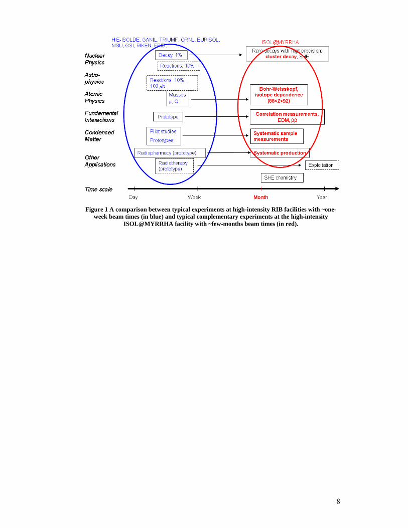
can profit from the unique possibilities of such an ISOL facility. This approach would complement other European RIB initiatives, as is illustrated in Figure 1, where a comparison is given between typical experiments at high-intensity RIB facilities with ~one-week beam times (in blue) and typical experiments at an high-intensity RIB facility with ~few-months beam times (in red). Such measurements requiring high-intensity beams and long beam times are an important source of information for quasi all fields in science making use of RIB’s, ranging from fundamental-interaction measurements with extremely high precision over systematic measurements for condensed-matter physics and production of radio-isotopes. The aim of the study is to lay down the general lines for RIB production and for a RIB research program followed by a feasibility study for such an ISOL facility, which has been named ISOL@MYRRHA.
This document gives a description of the ISOL@MYRRHA facility. Chapter 3 shows an overview of the MYRRHA project and facility. In chapter 4 a technical description of the ISOL@MYRRHA facility and its different components is given. Chapter 5 estimates the expected yields for different isotopes at ISOL@MYRRHA. Possible physics cases which can be addressed are briefly listed in chapter 6 and the final chapter sketches the foreseen timeline for the project.
8
Figure 1 A comparison between typical experiments at high-intensity RIB facilities with ~one-
week beam times (in blue) and typical complementary experiments at the high-intensity ISOL@MYRRHA facility with ~few-months beam times (in red).
9
3 3B3BThe MYRRHA project
3.1 8B10BIntroduction One of the major challenges that our society faces is the increasing demand for energy in general and electricity in particular. During the last century our energy supply was based on fossil fuels. Nowadays, we are confronted with decreasing hydrocarbon reserves and excessive CO2 emissions. At the same time renewable energy sources cannot satisfy the complete demand. For this reason the European Union, Japan, the United States, Korea, Russia, China, India and other countries recognize that nuclear energy needs to be part of the “energy basket” of the future.
Most present nuclear power reactors (GEN II & GEN III) operate with a thermal neutron spectrum, which implies that only a very limited fraction of natural uranium (basically 235U that is present at 0.7% in natural uranium) is being used. Reactors with a fast neutron spectrum (GEN IV) allow using the remaining 99.3% (238U) of mineral uranium as fuel by transforming 238U in 239Pu. This technology allows using the present uranium resources up to 50 times more efficiently leading to uranium resources for more than several thousands of years.
Apart from the large quantity of electricity, present nuclear reactors also produce high-level radioactive waste, for which a technical and socially acceptable solution is necessary. Transmutation of high-level radioactive elements with a long half-life present in the nuclear waste (like the minor actinides americium, curium and neptunium) allows reducing this time scale in a significant way. In order to transmute these elements with a long half-life in an efficient way, nuclear reactors with a fast neutron spectrum are necessary.
To develop the technologies associated with these fast reactors, an irradiation facility is needed. If one aims at transmuting large amounts of minor actinides in one installation, dedicated fast systems such as Accelerator Driven Systems (ADS) need to be used. The design and construction of such an installation for transmutation on a realistic scale is an essential step in developing the necessary technology and in the process that leads to the industrial application of this technique. Apart from energy production, other high-end technologies require irradiation facilities, e.g. the development of astronautics and telecommunication materials or the development of radioisotopes for medical applications.
MYRRHA will be a research facility that meets the requirements of the new irradiation facility mentioned above. In collaboration with different national and international partners, SCK•CEN, the Belgian Nuclear Research Centre in Mol, has been working towards the realization of such a facility since 1998, by means of intense design activities and a significant R&D support programme. MYRRHA is based on the principle of an ADS, also called a ‘hybrid reactor’. An ADS is a nuclear reactor with a subcritical core coupled to an external neutron source. In this context the term ‘subcritical’ means that the chain reaction is not self sustaining, contrary to classical reactors where criticality allows for a generation of neutrons to provide on average one neutron to the next generation. In order for an ADS to operate continuously, an external neutron source in necessary. These supplementary neutrons are produced by spallation reactions, during which high energy protons, coming from a particle accelerator, are impinging on a heavy metal like lead.
10
3.2 9B11BMajor MYRRHA design characteristics
Based on the scope of MYRRHA and the SCK•CEN objective to meet the international needs in terms of flexible fast spectrum irradiation capabilities and ADS demonstration and the targeted applications catalogue for this facility, the major design characteristics of MYRRHA are defined.
MYRRHA consists of a proton accelerator with 600-MeV proton energy and a design intensity of 4 mA, coupled to a liquid LBE spallation source. In the design of the accelerator, a possible upgrade to 1-GeV proton energy is foreseen in a later stage. The spallation target is located in the centre of a subcritical reactor core with a fast neutron spectrum and cooled with liquid lead-bismuth.
As a direct consequence of the desired high flux levels and hence high power density, a compact core is needed and therefore, the central hole in the core (which houses the spallation target) should be of limited dimensions (~ 10 cm diameter). Because of the desired high fast flux and the high power density and the short or medium term deployment of MYRRHA gaseous coolants are not eligible, therefore we opted for liquid metal as coolant. Sodium has not been retained due to the chemical reactivity with water and air and hence fire safety risks which is especially relevant in a flexible irradiation facility where many in-pile sections exist and loading/unloading operations of experiments during reactor operation occur. The alternative liquid metals as a coolant are lead and LBE. We opted for the latter due to its low melting temperature (124,5 °C), allowing the primary systems to function at rather low temperatures. These low working temperatures are an evident mitigating approach to limiting the corrosion problems due to Heavy Liquid Metal (HLM).
Inside the compact core geometry only an effective target diameter of about 88 mm is possible. With the given properties of the proton beam, this value leads to a beam current density of 65 µA/cm2. Although in principle a target window close to the spallation zone might be feasible, the possibility of window rupture and its consequences should always be taken into account. To avoid any difficulties with this failure mode, a windowless target design, i.e. without a physical separation between the accelerator beam line vacuum and the liquid target material, is envisaged. An additional advantage of a windowless spallation target design is that it can more easily be scaled up to higher beam currents needed for industrial scale transmuters.
The sub-criticality level of around 0.95 has been considered as an appropriate level for a first of a kind medium-scale ADS. Indeed, this is the criticality level accepted by the safety authorities for fuel storage and would allow for the MYRRHA concept to remain sub-critical even when accounting for the possible positive reactivity injections.
Taking into account the time schedule envisioned for the deployment of MYRRHA (start-up around 2020), the MYRRHA project team decided to use the most mature technologies whenever possible and in particular for the choice of the MYRRHA fuel. MOX fast reactor fuel technology has been chosen due to the large experience in Europe including Belgium. A maximum plutonium enrichment of 35 % was considered based on the available manufacturing and qualification experience in the past.
To profit from the thermal inertia provided by a large coolant volume, we opted for a pool-type system in which the components of the primary loop (pumps, heat exchangers, fuel handling tools, experimental rigs, etc) are inserted from the top in penetrations in the cover. The loading of fuel assemblies is foreseen to be from
11
underneath, which is not the classical approach of the sodium fast reactors. However the employed technology is the same. The reasons behind the approach are firstly to keep a large flexibility for the experimental devices loading from the top and secondly, from the safety point of view, the fact that all structures including the spallation module are in place before starting the core loading. The pool vessel, which contains the core of the MYRRHA machine and the whole series of internals, is located in an air-controlled containment environment. Furthermore, several factors lead to the decision to design both operation and maintenance and in-service Inspection & Repair of MYRRHA with fully-remote handling systems, among them:
• the high availability rate desired for the machine (70 to 75 %); • the high activation on the top of the reactor (due to the neutron leakage
through the beam line); • the alpha-radioactive polonium (Po) contamination when extracting
components; • the non-visibility under Pb-Bi; • the oxygen-free atmosphere in the MYRRHA hall.
3.3 10B12BApplications catalogue of MYRRHA MYRRHA should target the following applications catalogue:
• To demonstrate the ADS full concept by coupling the three components (accelerator, spallation target and sub-critical reactor) at reasonable power level to allow operation feedback, scalable to an industrial demonstrator. As such it will allow to study and provide feedback on: beam trips mitigation; sub-criticality monitoring and control; establishment of restart procedures after short or long stops; various reactivity injections in ADS; spallation products monitoring and control; component functioning.
• To allow study of the efficient transmutation of high-level nuclear waste, in particular minor actinides that would request high fast flux intensity (Φ>0.75MeV = 1015 ncm-2s-1)
• To be operated as a flexible fast spectrum irradiation facility allowing for:
fuel developments for innovative reactor systems; material developments for GEN IV systems; material developments for fusion reactors.
• Radioisotope production for medical and industrial applications • Industrial applications, such as Neutron Transmutation Doping (NTD) of
Si
3.4 11B13BThe implementation plan of MYRRHA
MYRRHA as a flexible fast spectrum irradiation facility able to operate in sub-critical and critical modes is intended to be started around 2020 at full power. In the

12
design and licensing of MYRRHA both modes of operation are foreseen from the beginning.
A minimum of two years preparatory period is considered for the progressive commissioning of the facility which will include both operation modes.
To obtain an answer on the viability of the ADS concept in an international context as soon as possible and thereby to allow to evaluate the realism of sub-critical burners in a double strata fuel cycle approach, it was opted to start in MYRRHA with the demonstration of ADS and hence the full power coupling with an accelerator. The international concern to decrease the half-life of the long-lived waste via Partitioning and Transmutation (P&T) (via dedicated sub-critical burners) is strongly shared by the Belgian government, supports the internationally oriented programme of SCK•CEN on the reduction of the half-life of the long-lived waste [reg08].
The MYRRHA facility is thus planned to be initially operated for several years as an ADS in sub-critical mode for the demonstration of the full power ADS operation and the efficient transmutation of minor actinides (with available fuels). During this period, MYRRHA will also be used as a flexible fast spectrum irradiation facility with the applications catalogue as described earlier. Within this applications catalogue the production of radio-isotopes is also of particular concern for the Belgian government [reg08].
Up till now, all flexible irradiation facilities have been operated very efficiently in critical mode. Working efficiently and reliably in sub-critical mode introduces heavy constraints on the accelerator. Since working in critical mode is not conditioned by this fact, it might be advantageous to work in critical mode. In this case, also electricity consumption which is mainly due to the accelerator can be significantly reduced which will decrease the operational costs of the facility. The facility will then be converted into a critical fast spectrum irradiation facility based on heavy liquid metal coolant technology by separating the accelerator from the reactor, by removing the spallation source and adding fuel assemblies to reach criticality.
In the central positions, which hosted the spallation source, an in-pile section with a maximum high flux can be inserted. MYRRHA will from then on be operated as a flexible fast spectrum irradiation facility with the applications catalogue as described earlier, except for the demonstration of the ADS concept. Further demonstration of efficient transmutation of minor actinides can be pursued in the critical MYRRHA, where new minor actinide fuels can be tested and qualified, albeit with a limited concentration of minor actinides. The maximum minor-actinide concentration in the critical reactor will be ~10 times less than in the sub-critical reactor.
13
4 4B4BISOL@MYRRHA: technical description
4.1 12B14BIntroduction Part of the nominal 4-mA MYRRHA Continuous Wave (CW) proton beam could be split off (up to 200 µA) during standard operation of MYRRHA and used for other research. An interesting approach is the installation of an Isotope Separator On-Line (ISOL) system to produce intense low-energy Radioactive Ion Beams (RIB) available for experiments requiring very long beam times. In the second phase, when the MYRRHA reactor will run as a stand-alone critical reactor, the full proton-beam intensity might be used for ISOL@MYRRHA or any other applications.
ISOL@MYRRHA will follow closely the RIB production schemes that are developed and successfully used at the ISOLDE-CERN and ISAC-TRIUMF facilities. It will be equipped with ruggedized target-ion source systems that allow the use of a selection of target materials, including actinide targets, that can withstand the proton beam power. Three types of ion sources are foreseen: hot cavity surface ion sources directly coupled to the high temperature target container, a Resonant Ionization Laser Ion Source (RILIS) that is also coupled to a high temperature container and finally a simple low-charge state Electron Cyclotron Resonance Ion Source (ECRIS) coupled to the target container via a cold transfer line beam production of gaseous elements. By using a part (up to 200 µA) of the 600-MeV proton beam, ISOL@MYRRHA will produce a wide spectrum of intense and pure radioactive Q = 1+ ion beams at 50-60 keV energies. The rationale behind the limited choice of simplified and ruggedized target-ion source systems for ISOL@MYRRHA is that the facility should deliver RIB for experiments needing very long beam times up to a few months, thus the number of target-ion source (TIS) changes should be minimal. In order to make effective use of the precious beam time, the parallel multi-users aspect of ISOL@MYRRHA is an important issue in the feasibility study.
4.2 13B15BBeam splitter The scenario is to operate both MYRRHA and ISOL@MYRRHA in parallel and simultaneously, and therefore a continuous beam splitter is required. It is considered that a fraction of up to 5% of the main beam (corresponding to 200 μA average current) can be delivered equivalently either in a CW mode or in a pulsed mode with sufficiently high repetition rate. So in the former case, a 5 % fraction from each of the bunches would be taken, whereas in the latter case the full bunch intensity would be used with a duty factor of 1/20. One must also consider the fact that the main beam will feature regular beam interruptions of 200 μs long with a requested repetition rate around 1 Hz, and that it is probable that these beam interruptions may be applied at a much higher repetition rate. This would give rise to a rough scenario where the 200 μs "holes" are taken out to the ISOL@MYRRHA experiment at a 250 Hz repetition rate, or at 125 Hz repetition rate for a 100 μA average current beam.
Since the two beams have to coexist in parallel operation, it is clear that some "extraction" mechanism has to be implemented, most probably featuring a septum as soon as the two beams are fully separated. It is also obvious that beam losses have to be kept at an extremely low level, hence the importance of preserving as much as possible the quality of the beams in terms of transverse emittance.

14
According to preliminary thoughts, three ways can be identified to achieve the goal.
1. An appealing method, and the only one to produce a truly CW secondary beam, would be to accelerate H- ions instead of protons, and to obtain the two beams by a partial stripping of the LINAC beam. According to which stripping mechanism is used one might favour the production of neutrals (H0) or protons (H+). An interesting possibility would be to cause electromagnetic stripping for a partial conversion into neutrals. This would have to occur in an undulator-like device in order to minimally disturb the main beam and to obtain a rather high quality neutral beam. This neutral beam can then be sent through a usual stripper foil so as to obtain a proton beam. The feasibility of this scheme in terms of efficiency of neutralisation has not been investigated here, because it is felt that the use of an H- beam has a number of prohibitive drawbacks in the framework of MYRRHA:
• Stripping of the very unstable H- ions will inevitably occur all along the LINAC and the main beam line, leading to significantly higher beam losses than in the case of a proton LINAC.
• Whereas the reliability of an ECR proton source is well established, the same technology cannot be used for the production of H-. The long term reliability of present day H- sources is questionable and definitely much lower than that of ECR sources.
• Even if a very carefully designed and adjusted magnetic device theoretically should not cause any deterioration of the main beam quality, the introduction of such a device will certainly considerably increase the risk in this domain. For any other stripping mechanism the quality of the primary beam will be affected.
For these reasons the use of H- beams is not further considered in this framework.
2. Bunch trains can be ejected from the main beam by a kicker magnet. A rise time of the order 1 μs (and much shorter) can doubtlessly be achieved with present day kicker technologies. Also the foreseen repetition rate does not at all touch the actual possibilities. An open question, though, is whether a flat top of 200 μs delimited by a rise time and a fall time of 1 μs may be achieved. In that case the pulse length would have to be reduced and the repetition rate increased. Of course, the beam has to be suppressed during the rise and fall times. This technique is a flexible and realistic solution which would have to be discussed further. However, there is serious concern about the reliability of the system and its components:
• Both the kicker magnet itself and its power supply are highly solicited
• Severe beam losses may occur upon kicks which are erroneous in amplitude (partial kicks) or in timing (spurious kicks)
3. Ejection of bunch trains from the main beam may also be obtained by a deflecting Radio Frequency RF cavity. Such a cavity would work at the same frequency as the main LINAC RF (704 MHz), and profit from the fact that in the high energy part of the linac every second RF bucket is empty (due to the frequency doubling at 100 MeV). Indeed, thanks to this all the bunches are deflected in the same direction by the cavity. The cavity would be normal

15
conducting in order to have short filling times and to allow for easy detuning. It should be complemented by a flat topping scheme, which is conveniently obtained by adding a 3rd harmonic cavity. The timing scheme of 200-μs pulses in a 5-% duty cycle seems to be realistic. The beam has to be suppressed during the transients, and their duration is expected in the μs region. A very rough estimate of the required drift length between the kick by the cavity and the entrance of the septum yields a reasonable value of 10 m. The feasibility, flexibility and robustness of this method have to investigated, but all appear as rather promising: the requested performances are rather conservative, and the RF operation guarantees the possibility of fast adjustments and of fast fault detection. The influence on the primary beam should be totally negligible.
Hence, one may state that the goal of generating a primary beam and a 5-% secondary beam in parallel seems to be realistic, given that the secondary beam may be delivered as a sequence of 200-μs pulses with a 250-Hz repetition rate. The presently favoured technical solution would consist of a deflecting RF cavity followed by a septum. The technique to be applied for such a cavity (or series of cavities) has to be investigated, also from the point of view of the reliability. Indeed, adding complexity to the accelerator of MYRRHA is only acceptable if the reliability of the added systems does not jeopardize the availability of the main beam. Finally, the septum is obviously a critical component, especially if an electrostatic version is chosen, where beam losses have to be limited to the sub-μA region. It also has to be emphasized that upgrading the proton accelerator to beam energies of 1 GeV would imply adjusting the beam splitter.
4.3 14B16BSpallation targets The high proton-beam intensity split off from the MYRRHA LINAC offers the possibility to deliver more intense radioactive ion beams compared to most of the present ISOL facilities like, e.g., ISOLDE, which operate at considerable lower beam intensities of typically ~2 μA (~10 μA at HIE-ISOLDE). The beam intensities as a function of the primary proton flux is expected to be linearly dependent on the proton flux Φp. In some specific cases, however, Radiation-Enhanced Diffusion (RED) [dom03] is observed resulting in an overall yield dependence of Φp
3/2 up to Φp2
instead of Φp. On the other hand, target degradation might reduce the ion-beam intensity. In our intensity estimates in chapter 4 a linear dependence will be assumed.
The high power that is deposited in the target needs to be dissipated efficiently [sto06]. Therefore, so-called high-power target systems are needed, which are capable to deal with a beam power of 60 kW (100 μA at 600 MeV), without compromising the reliability, the longevity, the diffusion and effusion properties, and the yield of particular radioactive isotopes. Temperature has to be maximized in the target and at the container inner wall to decrease the time constants of diffusion and effusion processes. At the same time, both target fast sintering and melting where the primary driver heat deposition is maximal, and uncontrolled cold spots where isotope condensation occurs, must be avoided. With an impinging beam power of 60 kW, the target temperature needs to be regulated by cooling.
The high power targets for ISOL@MYRRHA will be based on the expertise of TRIUMF, Vancouver (500 MeV proton beam) and the future EURISOL facility (1

16
GeV proton beam). To illustrate the feasibility of a 60 kW target station at ISOL@MYRRHA, some milestones are discussed in the development of high-power targets at TRIUMF [dom03,bri03,dom04,dom07,bri07,dom08].
• To dissipate the heat from the deposited beam power to the absorbing container wall, target materials with high thermal conductivity are required. At TRIUMF, one makes use of refractory-metal foils (e.g., Ta, Nb) and of carbide powders on a graphite sheet (e.g., SiC/C, TiC/C) in good thermal contact with the target container. The carbide target material is layered onto a thin graphite sheet to enhance the heat transfer capability. The composite sheets are cut in the same shape as used for the metal foil targets and stacked in the target container in an analogous manner. By cutting the disks slightly oversize, a good edge contact with the target container is ensured. Operational proton beam currents of 35-40 μA can be used on the resulting target system.
• In order to go to higher proton intensities on both metal and composite carbide targets, it was necessary to increase the radiative cooling of the standard target container. From the different cooling schemes that have been proposed over the last ten years, it is clear that radiative cooling offers the simplest approach. To date, it is the only scheme that is currently applied on high-power targets. The idea of radiative cooling is to increase the effective emissivity of the target container. One could enhance the effective emissivity from 0.35 to 0.92 by placing radial fins around the target container. The operational proton beam limit further increased to 70-75 μA.
• While increased radiation can lead to the effect of RED, the same radiation can have a detrimental effect of target longevity. Higher proton currents not only produce the desired products, but also elements that can be considered as impurities in both the target material and the metal of the target container. These impurities can form stable compounds with target materials, which are not released from the target, but instead diffuse and build up at grain boundary sites. The build up of impurities eventually leads to a loss of integrity in the target container. Although it affects the metal-foil targets as well, carbide targets turned out to be more sensitive due to compound formation between target material and target container. The carbide targets react with the tantalum target container to form the very stable TaC carbide. By coating the inner surface of the target container with a sintered layer of TaC prior to loading of the target discs, the radiation damage shows to be more consistent with the metal-foil targets and operation times of over two months were reached.
• In 2007, continuous operation of a Ta target at 100 μA (50 kW beam power) was demonstrated for a period of one week. Currently, the limiting factor is the proton beam size. The primary beam has to be defocused in order to avoid melting the entrance window of the target container and overheating the target central region. As a result, however, the target container receives more protons and looses its integrity caused by the radiation damage. To overcome this, a rotating beam is being installed at TRIUMF that will allow the use of a narrow beam. Beam power deposited close to the target wall container would be more efficiently dissipated and a higher beam power density may also enhance product release through increased RED effects. One expects that beam intensities larger than 100 μA will be possible and that 200 μA (100 kW beam power) is a reasonable goal.

17
Thermal simulations carried out in the framework of the EURISOL design study [sto06] indicate that a 100-μA proton beam at 1 GeV deposits a total power of 24 kW in a nominal SiC/C target, while it is able to radiate up to 25 kW for an effective emissivity of 0.8. However, the computed peak temperature was very close to the SiC melting point and strong temperature gradients were obtained. For more uniform beam power deposition, a 3-compartment design is considered with a low material density in the first compartment and increasing in the two consequent ones. The total deposited power in this configuration is only 18.5 kW. It is expected that this design can withstand about 20 kW of deposited power.
Although metal-foil targets can deal with a power dissipation of up to 25 kW, a multi-container system is proposed in the EURISOL design study to extend the range of dissipated power [sto06,wil07].
Note that the deposited power in the TRIUMF target design at beam intensities of 45 μA is 5 kW, while from their expertise it is expected that beam intensities up to 200 μA will be feasible.
In view of the developments at TRIUMF and the EURISOL design study discussed above, the selected target materials for ISOL@MYRRHA should be thin refractory metal foils and carbide powders on a graphite sheet, which can be expected to be operated at the full power of 60 kW. Important to note is the possibility to exploit UCx/C as a workhorse target within the nuclear site of SCK•CEN.
4.4 15B17BIon sources When choosing ion sources for on-line systems, usually, ionisation efficiency and selectivity, reliability, and intrinsic short delays are the main selection criteria. For the ISOL@MYRRHA system, being focussed on long beam-times with stable operation it is essential that the ion sources should preferably be very ruggedized systems. The ionisation efficiency for different types of ion sources as a function of the electron affinity/ionisation potential is shown in Figure 2. It is clear that for different types of atoms, specific type of ion sources are needed. As an optimal answer to both the reliability requirement and the fact that for all atoms produced a rather efficient and preferably selective ionisation is needed, three types of ion sources were selected: a surface ion source, an Electron-Cyclotron Resonance Ion Source (ECRIS) and a Resonant Ionization Laser Ion Source (RILIS).

18
Figure 2. Ionisation efficiencies for different ion source types as a function of the ionisation
potential: green marks for ECRIS, circles for a Forced Electron Beam Induced Arc Discharge (FEBIAD) source, yellow triangles for Resonant Ionisation Laser Ion Source (RILIS), black diamond for a W surface-ion source, and orange marks for a LaB6-surface kinetic-ejection
negative-ion source. Picture taken from Ref. [let08].
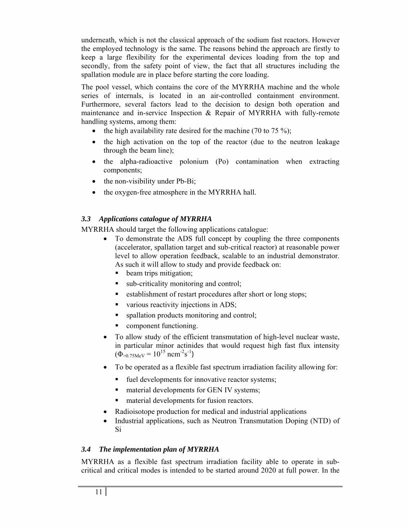
4.4.1 24B26BSurface ionisation In a surface ion source a hot surface of a metal with a high work function is placed in a hot cavity into which the radioactive atoms that are produced in the target stack are entered. Possible candidate materials are Ta, W and Re with a work function of 4.19 eV, 4.53 eV and 5.1 eV, respectively. When an atom with an ionisation potential that is lower than the work function of the metal hits the hot surface, an electron is absorbed in the metal and the atom is ionised. As a result of this requirement, surface ionisation is only efficient for alkali elements which on the other hand has the advantage that surface ionisation is also a selective method. In addition, thanks to their simple design and the fact that those metals with a high work function also have a very high melting point, surface ion sources are very robust and reliable in their operation. The process is schematically shown in Figure 3.
19
Figure 3. A schematic drawing of the surface ionisation principle. Picture taken from Ref.
[kös08].
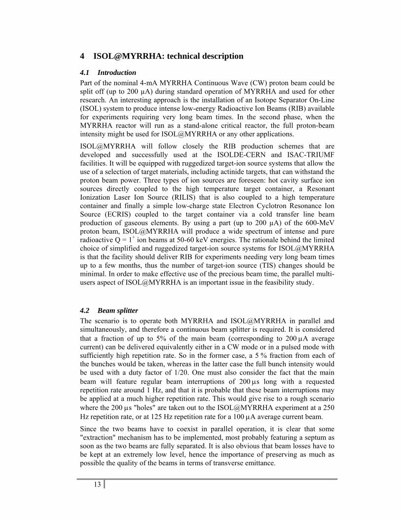
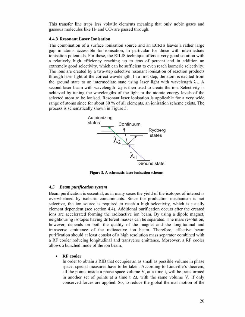
4.4.2 25B27BElectron cyclotron resonance ion source The electron cyclotron resonance is based on an electron cloud that is locked in a magnetic-bottle field configuration and resonantly accelerated by an RF field matching the cyclotron frequency of the electrons. Repeated collisions of the electrons with the gaseous atoms create a plasma in which the radioactive atoms are ionised. The ECRIS is very efficient for ionisation of gaseous elements (see also Figure 2), but lacks selectivity. ECRIS are often used to create highly charged ions. For use at ISOL@MYRRHA, it is in principle sufficient to create the low-charged (1+) ions. A schematic drawing of an ECRIS is shown in Figure 4.
Figure 4. Schematic drawing of an ECRIS.
A proven method to enhance the selectivity of an ECRIS is the combination of the ion source with a cooled transfer line between the target and the ionisation chamber.
20
This transfer line traps less volatile elements meaning that only noble gases and gaseous molecules like H2 and CO2 are passed through.
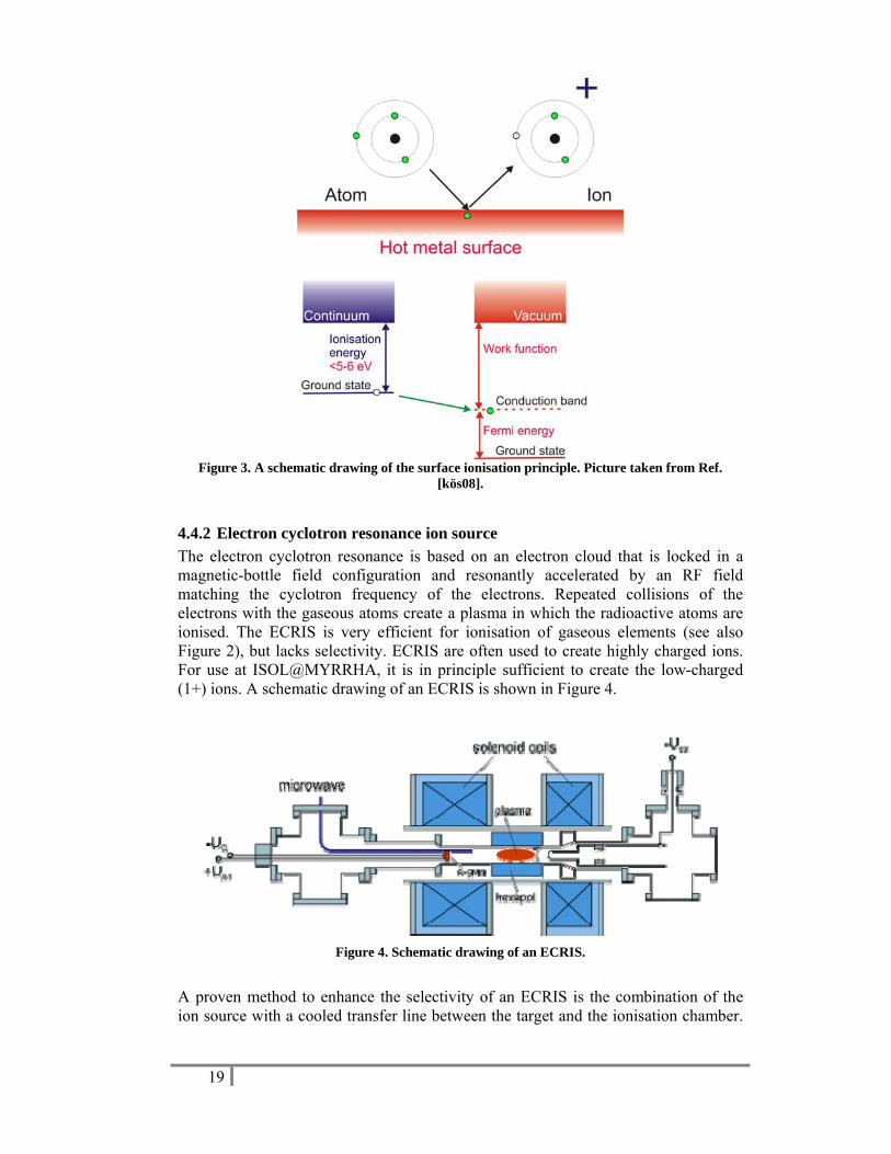
4.4.3 26B28BResonant Laser Ionisation The combination of a surface ionisation source and an ECRIS leaves a rather large gap in atoms accessible for ionisation, in particular for those with intermediate ionisation potentials. For these, the RILIS technique offers a very good solution with a relatively high efficiency reaching up to tens of percent and in addition an extremely good selectivity, which can be sufficient to even reach isomeric selectivity. The ions are created by a two-step selective resonant ionisation of reaction products through laser light of the correct wavelength. In a first step, the atom is excited from the ground state to an intermediate state using laser light with wavelength λ1. A second laser beam with wavelength λ2 is then used to create the ion. Selectivity is achieved by tuning the wavelengths of the light to the atomic energy levels of the selected atom to be ionised. Resonant laser ionisation is applicable for a very wide range of atoms since for about 80 % of all elements, an ionisation scheme exists. The process is schematically shown in Figure 5.
Figure 5. A schematic laser ionisation scheme.
4.5 16B18BBeam purification system Beam purification is essential, as in many cases the yield of the isotopes of interest is overwhelmed by isobaric contaminants. Since the production mechanism is not selective, the ion source is required to reach a high selectivity, which is usually element dependent (see section 4.4). Additional purification occurs after the created ions are accelerated forming the radioactive ion beam. By using a dipole magnet, neighbouring isotopes having different masses can be separated. The mass resolution, however, depends on both the quality of the magnet and the longitudinal and transverse emittance of the radioactive ion beam. Therefore, effective beam purification should at least consist of a high resolution mass separator combined with a RF cooler reducing longitudinal and transverse emittance. Moreover, a RF cooler allows a bunched mode of the ion beam.
• RF cooler In order to obtain a RIB that occupies an as small as possible volume in phase space, special measures have to be taken. According to Liouville’s theorem, all the points inside a phase space volume V, at a time t, will be transformed in another set of points at a time t+Δt, with the same volume V, if only conserved forces are applied. So, to reduce the global thermal motion of the
21
ions in the beam, a cooling method (i.e., introducing external forces) is needed. For RIBs, the cooling method should be universal (element independent) and fast (to minimize decay losses of nuclei with short half-lives). Studies have shown that in this case buffer-gas cooling is the best option, because it depends only on the mass of the ions and cooling times of a few milliseconds are normally sufficient, see, e.g., Ref. [äys03] for a review of cooling applications. The buffer-gas cooling technique is based on the reduction of the motion amplitude of the ions that are trapped into an electromagnetic ion trap due to collisions with buffer-gas atoms or molecules. As a result, the ion-optical properties can be significantly improved (i.e., energy dispersion, beam spot size and divergence) and ion-beam bunching becomes possible. Typically, helium at a pressure of about 0.1 mbar is used as the buffer gas. To counteract thermal diffusion caused by the gas-ion collisions, the ions need to be confined by a trap. Two main types of ion traps can be used: Penning traps, which combine a magnetic and an electrostatic field, and Paul traps, which in its simplest form consist of four aligned rods on which a RF signal is applied and that create a quadrupole field. Paul traps are the most frequently used for ion beam cooling, because of their relative simple construction and operation. An RF cooler can be divided in three parts. The injection part contains electrodes to decelerate the RIB (~50 keV) down to the injection energy of the RF cooler (~100 eV). The accumulation part encloses the buffer gas and contains the linear Paul Trap. Additionally, axial electrodes can create a potential well in the longitudinal direction to, e.g., confine the beam, create bunches or to guide the ion cloud to the extraction region. The third part, the extraction region, contains the electrodes to accelerate the ions from thermal energies to RIB energies. Representative transmission efficiencies of RF coolers are shown in Ref. [frå08], where off-line test results of the ISCOOL (ISOLDE COOLer) device [ali06] are discussed with different RIBs of alkali metals. Optimized transmission efficiencies of 17, 28, 68, and 79 % are reached for lithium, sodium, potassium, and cesium beams, respectively. Comparable on-line transmission efficiencies of 60-70 % are obtained with the JYFL cooler [äys03]. Although current RF cooler devices operate successfully, they are limited by a maximum intensity of the injected ion beam (up to 10 nA) caused by the space charge limit. In the framework of the EURISOL Design Study, an RF cooler is being developed that is able to accept microampere beams [lun09] by further increasing both the RF amplitude and frequency.
• High-Resolution mass separator
A typical ISOL system will have a magnetic mass separator to perform isobaric mass separation of the produced ions. Because of the presence of an RF cooler, the emittance of the ion beam is improved to such level that the full potential of a high resolution separator can be exploited. Clearly, the better the resolution of the separation mechanism, the higher the suppression of contaminant ion species will be. Thanks to a gas catcher-cooler combination in the CARIBU project, for example, a

22
low-emittance ion beam can be obtained allowing a mass resolution of M/ΔM ≥ 20,000 [dav08].
Since a high-resolution separator prevents the use of different beams at the same time, a pre-separator with low mass resolution should be considered. In this way, one could envisage a scenario in which the low mass isotopes (8Li) are used for solid-state physics at the same time as the physics use for the higher masses.
4.6 17B19BInfrastructure In this section the current situation of the global layout of the MYRRHA facility is presented. This layout has been studied in the framework of the FP6 IP_EUROTRANS project and are currently under investigation in the framework of the FP7 CDT project, in close collaboration with SCK•CEN. It will be shown that the facilities for ISOL@MYRRHA can be introduced in the current layout.
4.6.1 27B29BInstallation of the MYRRHA facility on the Mol site: general considerations
It has to be considered that many facilities that can be of use for MYRRHA are already available on the technical site (see Figure 6). The global layout study did therefore not start from scratch. The total surface available at Mol is about 500 hectares, from which 10 % is considered as "technical domain" where buildings may be built; the rest being considered as "woods" where a special procedure should be followed for installing new buildings.
Figure 6. Location of existing facilities on the SCK•CEN technical site.
23
4.6.2 28B30BLocation of MYRRHA on the SCK•CEN site It is considered to install the most critical series of buildings, namely the combination in a straight line of the front end of the accelerator (purple colour, 80 m length, 60 m width), the accelerator tunnel (blue colour, 220 m length, 28 m width) and the reactor building for which we have taken the reference "MYRRHA DRAFT–2" building dimensions (green colour, 110 m length, 30 m width) (see Figure 7).
This combination is the most demanding: it is not considered at this stage the possibility to fold the accelerator tunnel; an alternative, more quadratic shape (70 m length, 50 m width), exists for the MYRRHA building.
Three locations are currently being investigated (see Figure 7):
• Location (1) lies at the western part of the technical domain. In the actual dimensions and because of the "reserved" area for the EIG, this option cannot be retained, except if some fine tuning in the localisation can be made. Anyway the total available area is still limited; there would be no possibility to extend the accelerator tunnel, the bearing sands would be of lower quality being in the vicinity of a lagoon. Therefore location (1) is considered as "less suitable".
• Location (2) lies in the centre of the technical domain and was the favoured solution in the earlier stages of the study. It remains a good solution in the actual dimensions. However, we prefer to install the reactor building (green colour), which needs to go partially underground, in the southern part far enough from the existing buildings. An extension of the accelerator tunnel is possible (about 100 m length).
• The most promising solution is location (3), in an area sufficiently far away from the existing buildings and where a large area remains aside (150 m by 250 m) for the auxiliary buildings to be constructed. As for location (2), an extension of the accelerator tunnel is possible (about 100 m length). We consider therefore locations (2) and (3) as very suitable for the purpose, but the main option is solution (3).
4.6.3 29B31BDetailed implementation of MYRRHA In the framework of FP6 IP_EUROTRANS, a next step was undertaken to organise, in the most coherent way, the auxiliaries around the reactor and the accelerator main buildings. A typical solution is presented in Figure 8, showing that the whole area is occupied. Currently, under FP7 CDT, a project to consider the MYRRHA facility from the beginning considered as being able to function first in sub-critical mode and then in critical mode has been launched. This would have implications for the size and dimensions of the main reactor building, but also for the power level of the facility, with direct implications for the auxiliary buildings.
4.6.4 30B32BImplementation of ISOL@MYRRHA The preferred third option for the implementation of MYRRHA at the SCK•CEN site, allows for the construction of a well shielded target-ion source area and an experimental hall (20 x 50 m2). Furthermore, the necessary expertise in handling of high-radioactive targets, including actinide targets, and hot cells is available at SCK•CEN. Currently, there are more than 20 operational hot cells at SCK•CEN

24
resulting from a 40 years of experience. The hot cells are licensed for two different radiological applications: (i) one for handling beta- or gamma-active materials and (ii) a second class for handling alpha-contaminated materials. ISOL@MYRRHA can, thus, substantially benefit from this expertise at SCK•CEN, which becomes particularly crucial when making use of uranium-carbide targets.
Figure 7. Possible locations of the ISOL@MYRRHA main buildings on the SCK•CEN technical
site.
Figure 8. Global plant layout (from the EA report).

25
5 5B5BExpected yields The radioactive beam intensity I that may be obtained can be determined from the equation 1 2 3I Nσφ ε ε ε= where σ is the formation cross section for the nuclear reactions of interest, φ the primary-beam intensity, N the usable target thickness, ε1 the transport efficiency from the point where the nucleus is produced to the exit of the ion source (i.e., the fraction of nuclei that did not suffer radioactive decay), ε2 the ion-source efficiency, and ε3 the transport efficiency through the separator.
Typically three nuclear reactions are induced by a proton beam impinging on a thick target, i.e., spallation, fission and fragmentation reactions. The in-target production can be calculated with the appropriate reaction cross sections. Semi-empirical values have been computed by Silberberg and Tsao [sil99] and, more recently, a numerical code ABRABLA is developed and benchmarked against experimental results in reverse kinematics at GSI [luk06], which provides reliable in-target yields. The three nuclear-reaction types are indicated in Figure 9 for a p+238U reaction, where total cross sections are compared for a 600-MeV (e.g., ISOL@MYRRHA), 1-GeV (e.g., EURISOL), and 1.4-GeV (e.g., ISOLDE-PSB) beam. It can be noticed that the fission cross section is rather energy independent. Also the spallation cross sections for the 6-7 elements nearest to uranium are not very sensitive to differences in proton energy. However, the deep-spallation and fragmentation reactions show a strong energy dependency. The particular interest in the production of light elements, like lithium or beryllium, is, therefore, an important incentive for the upgrade to a 1-GeV proton accelerator. It is, for example, commonly known that currently the highest 11Li production yields are delivered by the TRIUMF facility in Canada, where proton beam energies of only 500 MeV are used. Comparing the 11Li yields as given in the TRIUMF and ISOLDE-PSB on-line databases [tri09,iso09] reveal respective absolute values of 15000 s-1 at 75 μA and 7000 s-1 at 1 μA, but normalized to the beam intensity, this becomes 200 μC-1 and 7000 μC-1, respectively.
Figure 9 Total cross section of a p+238U reaction as a function of atomic number Z, as calculated
with the CASCABLA code. Curves for three different proton energies are shown: 600 MeV (green), 1 GeV (red), and 1.4 GeV (blue). Picture is taken from Ref. [let08].
26
After their in-target production, isotopes must be efficiently transported towards the ion source. This occurs through diffusion out of the matrix material, effusion towards the target external surface, and effusion in the container and transfer line. Diffusion time constants can be deduced experimentally from specific isotope release curves. To determine the effusion delay time, however, a precise knowledge is required of the temperature profile in the full target and ion-source assembly, of the target microstructure and its specific surface, and of representative sticking times.
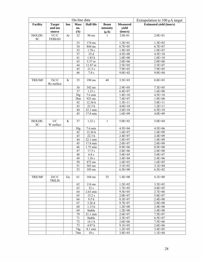
Instead of going through the tedious process of determining diffusion constants and simulating effusion delay times, the expected yields at the ISOL@MYRRHA facility are estimated by linearly extrapolating the available production yields listed in the ISOLDE-SC (600-MeV proton beam on UC target) [iso09] and ISAC (500-MeV proton beam on Ta, SiC/C, TiC/C, and ZrC/C targets) [tri09] data bases, see Table 1, whereby it is assumed that diffusion and effusion losses (ε1), the ion-source efficiencies (ε2), and the separator transport efficiencies (ε3) stay the same. In case fission yields for an UC/C are estimated involving resonant laser ionization, like for the Ga isotopes in Table 1, values listed in the ISOLDE-PSB (1.4 GeV proton beam on UC target) [iso09] data base can be used for the extrapolations. While higher proton-beam energies enhance significantly spallation and fragmentation yields, fission yields are much less sensitive to the primary proton-beam energy. On the other hand, the yields at the neutron-deficient side are overestimated. As motivated in section 4.3, the selected target materials for ISOL@MYRRHA are metal foils and carbide powders on a graphite sheet.
Several issues should be noted:
• For most of the elements, the UC/C target is complementary with the lower Z spallation targets. While the latter have high production rates for the more neutron-deficient isotopes, the former has higher production rates for the neutron-rich isotopes.
• In case of the lightest elements, it seems that the UC/C target is typically the best option. The estimated Li isotope yields are almost one order of magnitude higher with the UC/C target than with the Ta target. On the other hand, studies in the framework of EURISOL-DS have shown that the in-target yields of AlO or SiC targets are higher than those of UC targets, in particular at incident proton energies below 1 GeV [cha08].

27
Table 1. Estimated RIB intensities for a direct 100-μA proton beam on ruggedized targets. On-line data Extrapolation to 100 μA target
Facility Target and ion source
Ion Mass no. (A)
Half-life Beam intensity
(μA)
Measured yield
(ions/s)
Estimated yield (ions/s)
TRIUMF Ta Re Surface
Li 6 Stable 35 6.1E+09 1.7E+10
7 Stable 60 4.5E+10 7.5E+10 8 838 ms 75 5.5E+08 7.3E+08 9 178 ms 75 7.7E+07 1.0E+08 11 8.5 ms 75 1.5E+04 2.0E+04
ISOLDE-SC
UC W surface
Li 7 Stable 1 8.2E+09 8.2E+11
8 838 ms 5.8E+07 5.8E+09 9 178 ms 3.9E+06 3.9E+08 11 8.5 ms 1.4E+03 1.4E+05
TRIUMF SiC/C FEBIAD
Ne 17 109 ms 75 1.7E+05 2.3E+05
18 1.672 s 7.9E+06 1.1E+07 19 17.34 s 6.9E+07 9.2E+07 23 37.24 s 4.2E+07 5.6E+07 24 3.38 min 1.5E+06 2.0E+06 25 602 ms 3.9E+02 5.2E+02
TRIUMF SiC/C Re surface
Na 20 448 ms 70 1.7E+08 2.4E+08
21 22.48 s 1.1E+10 1.6E+10 24 14.96 h 6.5E+10 9.3E+10 25 59.6 s 2.2E+09 3.1E+09 26 1.07 s 3.9E+07 5.6E+07 27 304 ms 1.5E+06 2.1E+06
ISOLDE-SC
UC W surface
Na 21 22.48 s 1 1.8E+04 1.8E+06
24 14.96 h 5.5E+06 5.5E+08 25 59.6 s 6.4E+06 6.4E+08 26 1.07 s 1.3E+06 1.3E+08 27 304 ms 3.1E+05 3.1E+07 28 31 ms 1.3E+04 1.3E+06 29 45 ms 4.5E+03 4.5E+05 30 48 ms 6.4E+02 6.4E+04 31 17 ms 6.6E+01 6.6E+03 32 13 ms 7.2E+00 7.2E+02 33 8 ms 8.8E+00 8.8E+02 34 6 ms 2.8E+00 2.8E+02
TRIUMF TiC/C FEBIAD
Ar 33 174 ms 70 7.0E+02 1.0E+03
34 844 ms 2.9E+03 4.14E+03 35 1.78 s 6.5E+06 9.29E+06 41 1.83 h 7.0E+08 1.0E+09 43 5.37 m 1.6E+07 2.29E+07 44 11.87 m 2.2E+06 3.14E+06 45 21.5 s 7.5E+04 1.07E+05
28
On-line data Extrapolation to 100 μA target Facility Target
and ion source
Ion Mass no. (A)
Half-life Beam intensity
(μA)
Measured yield
(ions/s)
Estimated yield (ions/s)
ISOLDE-SC
VC/C FEBIAD
Ar 32 98 ms 1 2.0E-01 2.0E+01
33 174 ms 1.3E+01 1.3E+03 34 844 ms 6.7E+05 6.7E+07 35 1.78 s 1.9E+05 1.9E+07 37 35 d 4.5E+08 4.5E+10 41 1.83 h 1.0E+08 1.0E+10 43 5.37 m 2.0E+06 2.0E+08 44 11.87 m 2.5E+05 2.5E+07 45 21.5 s 7.9E+03 7.9E+05 46 7.8 s 9.0E+02 9.0E+04
TRIUMF TiC/C Re surface
K 35 190 ms 40 3.5E+03 8.8E+03
36 342 ms 2.9E+05 7.3E+05 37 1.23 s 6.4E+07 1.6E+08 38g 7.6 min 1.8E+10 4.5E+10 38m 925 ms 7.4E+07 1.9E+08 42 12.36 h 1.5E+11 3.8E+11 43 22.3 h 4.6E+10 1.2E+11 44 22.1 min 2.6E+10 6.5E+10 45 17.8 min 1.6E+09 4.0E+09
ISOLDE-SC
UC W surface
K 37 1.23 s 1 5.0E+02 5.0E+04
38g 7.6 min 4.5E+04 4.5E+06 42 12.36 h 1.6E+07 1.6E+09 43 22.3 h 2.4E+07 2.4E+09 44 22.1 min 1.8E+07 1.8E+09 45 17.8 min 2.0E+07 2.0E+09 46 1.75 min 8.9E+06 8.9E+08 47 17.5 s 2.8E+06 2.8E+08 48 6.8 s 5.0E+05 5.0E+07 49 1.26 s 2.4E+04 2.4E+06 50 472 ms 1.6E+03 1.6E+05 51 365 ms 3.1E+02 3.1E+04 52 105 ms 6.5E+00 6.5E+02
TRIUMF ZrC/C TRILIS
Ga 61 168 ms 35 1.4E+00 4.1E+00
62 116 ms 1.2E+02 3.3E+02 63 32 s 1.7E+05 4.8E+05 64 2.63 min 9.5E+05 2.7E+06 65 15.2 s 2.0E+07 5.8E+07 66 9.5 h 8.3E+07 2.4E+08 67 3.26 d 9.7E+07 2.8E+08 68 1.13 h 1.2E+08 3.4E+08 69 Stable 1.2E+08 3.4E+08 70 21.1 min 2.6E+07 7.5E+07 71 Stable 2.3E+07 6.5E+07 72 14.1 h 2.6E+06 7.5E+06 73 4.87 h 9.1E+05 2.6E+06 74g 8.1 min 1.2E+05 3.4E+05 74m 10 s 3.8E+03 1.1E+04

29
On-line data Extrapolation to 100 μA target Facility Target
and ion source
Ion Mass no. (A)
Half-life Beam intensity
(μA)
Measured yield
(ions/s)
Estimated yield (ions/s)
75 2.1 min 1.3E+03 3.8E+03
ISOLDE-PSB
UC RILIS
Ga 70 21.1 min 1 1.3E+05 1.3E+07
73 4.87 h 4.8E+05 4.8E+07 74g 8.1 min 5.2E+05 5.2E+07 75 2.1 min 8.3E+05 8.3E+07 76 32.6 s 7.0E+05 7.0E+07 77 13.2 s 7.6E+05 7.6E+07 78 5.09 s 5.5E+05 5.5E+07 79 3 s 6.5E+05 6.5E+07 80 1.697 s 3.1E+05 3.1E+07 81 1.221 s 1.9E+05 1.9E+07 82 599 ms 3.0E+04 3.0E+06 83 310 ms 4.5E+03 4.5E+05 84 85 ms 8.0E+01 8.0E+03 85 1.2E+01 1.2E+03 86 1.5E+00 1.5E+02
TRIUMF ZrC/C Ta surface
Rb 75 19 s 35 2.8E+06 8.0E+06
76 37 s 5.3E+07 1.5E+08 77 3.8 min 1.6E+09 4.6E+09 78g 17.5 min 2.2E+09 6.3E+09 78m 5.7 min 6.9E+09 2.0E+10 79 23.2 min 4.1E+10 1.2E+11 80 33 s 3.5E+10 1.0E+11 81g 4.6 h 3.3E+10 9.4E+10 81m 30.5 min 6.8E+10 1.9E+11 82g 1.3 min 7.8E+09 2.2E+10 82m 6.5 h 9.5E+10 2.7E+11 83 86.2 d 2.2E+11 6.3E+11 84m 20.3 min 2.9E+10 8.3E+10 88 17.7 min 1.3E+09 3.7E+09 89 15.4 min 1.4E+09 4.0E+09 90g 2.6 min 2.6E+07 7.4E+07 90m 4.3 min 4.1E+07 1.2E+08 91 58 s 2.7E+07 7.7E+07 92 4.5 s 2.3E+05 6.6E+05 93 5.9 s 8.2E+03 2.3E+04
ISOLDE-SC
UC W surface
Rb 79 22.9 min 1 3.6E+05 3.6E+07
80 34 s 1.6E+07 1.6E+09 81 4.6 h 7.1E+06 7.1E+08 86 18.6 d 2.0E+08 2.0E+10 90 158 s 5.0E+08 5.0E+10 92 4.5 s 2.0E+08 2.0E+10 93 5.7 s 1.3E+08 1.3E+10 94 2.7 s 1.0E+08 1.0E+10 95 377 ms 4.0E+07 4.0E+09 96 199 ms 1.4E+07 1.4E+09 97 172 ms 5.6E+06 5.6E+08 98 114 ms 3.2E+06 3.2E+08

30
On-line data Extrapolation to 100 μA target Facility Target
and ion source
Ion Mass no. (A)
Half-life Beam intensity
(μA)
Measured yield
(ions/s)
Estimated yield (ions/s)
99 59 ms 4.0E+05 4.0E+07 100 51 ms 2.5E+04 2.5E+06 102 37 ms 2.5E+02 2.5E+04
TRIUMF Ta TRILIS
Ag 98 47.4 s 35 3.9E+01 1.1E+02
99 2.1 min 3.2E+02 9.1E+02 100g 2 min 2.5E+03 7.1E+03 100m 2.3 min 1.6E+04 4.6E+04 101g 11.4 min 2.4E+04 6.9E+04 101m 3.1 s 7.5E+02 2.1E+03 102g 13 min 1.9E+05 5.4E+05 102m 7.8 min 9.4E+04 2.7E+05 103g 1.1 h 8.5E+05 2.4E+06 103m 5.7 s 4.8E+06 1.4E+07 104g 1.15 h 1.1E+06 3.1E+06 104m 33 min 1.9E+05 5.4E+05 105m 7.2 min 7.2E+06 2.1E+07 107m 44.2 s 1.2E+06 3.4E+06 109m 39.8 s 3.7E+06 1.1E+07 110g 24.6 s 2.0E+05 5.7E+05 111m 1.08 min 4.0E+04 1.1E+05 112 3.03 h 2.9E+06 8.3E+06 113m 1.14 min 1.0E+05 2.9E+05 116m 9 s 1.3E+03 3.7E+03 117g 1.22 min 2.1E+03 6.0E+03 117m 5.3s 3.0E+02 8.6E+02
ISOLDE-SC
UC W surface
Fr 201 53 ms 1 1.0E+00 1.0E+02
202 340 ms 7.1E+01 7.1E+03 203 560 ms 1.0E+03 1.0E+05 205 3.9 s 1.7E+05 1.7E+07 206 15.9 s 2.4E+06 2.4E+08 207 14.8 s 3.6E+06 3.6E+08 208 58.6 s 2.5E+07 2.5E+09 209 50 s 7.5E+07 7.5E+09 210 3.18 min 1.3E+08 1.3E+10 211 3.1 min 1.5E+08 1.5E+10 212 20 min 1.6E+08 1.6E+10 213 34.6 s 3.4E+07 3.4E+09 214 5 ms 9.4E+02 9.4E+04 218 1 ms 4.3E+03 4.3E+05 219 20 ms 8.9E+03 8.9E+05 220 27.4 s 3.8E+07 3.8E+09 221 4.9 min 2.8E+07 2.8E+09 222 14.4 min 1.0E+07 1.0E+09 224 3.3 min 1.4E+06 1.4E+08 226 48 s 3.6E+05 3.6E+07 228 39 s 8.9E+04 8.9E+06 229 50 s 3.8E+04 3.8E+06 230 19.1 s 5.6E+03 5.6E+05

31
32
6 6B6BPhysics research at ISOL@MYRRHA
6.1 18B20BIntroduction In this chapter, different possibilities for physics research at ISOL@MYRRHA, based on ideas presented during the 2008 BriX workshop (Mol, Belgium), are discussed. As illustrated in the overview of Figure 10, measurements with high-intensity beams and long/regular beam times are an important source of information for quasi all fields in science making use of RIBs, ranging from fundamental-interaction measurements with extremely high precision over systematic measurements for condensed-matter physics and production of radio-isotopes. Experiments, which need very high statistics, need many time-consuming systematic measurements, hunt for very rare events, and/or have inherent limited detection efficiency are particularly interested in extended beam times. Long beam times could be of interest for astro-physics, when nuclear reactions with small cross sections are involved, but the absence of a post-accelerator in the present phase of ISOL@MYRRHA will prevent such kind of studies. Although higher-energy secondary beams are not discarded for a later phase, the focus in this report will be on physics cases with beam energies up to 60 keV. Indicated in Figure 10 in red font are typical examples of experiments over the different fields, which can be uniquely conducted at a facility like ISOL@MYRRHA.
Weak-interaction studies are used for investigating fundamental interactions and testing the standard model via, e.g., measuring Ft values and investigating specific correlations in the β-decay process as precise as possible. In atomic physics, quantum- electrodynamics (QED) tests in strong electromagnetic fields (available in one-electron high-Z systems) are still lacking. Systematic high-precision (10-9) g-factor measurements of the elements between bismuth and uranium, which can only be produced at a RIB facility, constitute a stringent test. Moreover, the high intrinsic precision of atomic-physics techniques allows the measurement of small nuclear-structure induced effects, like the Bohr-Weisskopf effect. As these experiments strive to the highest possible precision, the systematic errors in the experimental setup have to be understood as good as possible and large statistics are of primordial importance. In nuclear physics, determining precise values of extremely small decay branches (in the order of 10-6) or crystal γ-ray spectrometry with very high resolution can provide crucial experimental input for understanding aspects of nuclear structure. In order to obtain the desired statistics with such rare-event decays or inherent limited detection efficiencies of crystal spectrometers, not only high-intensity beams, but also the availability of long beam times can be of crucial importance. In condensed-matter physics and biology, techniques like 8Li β-NMR and emission channelling with short-lived isotopes could profit from the available long beam times. Systematic measurements allow the different investigation of samples, which give rise to a more detailed study. In the situation of radio-pharmacy, radio-isotopes for medical applications could be systematically produced in very clean conditions. In the following sections, each of these fields will be discussed in greater detail.

33
Figure 10 Illustration of the possible RIB research by exploiting the availability of long beam times at ISOL@MYRRHA (more detailed version of Figure 1). Indicated in red font are typical examples of experiments, which can be uniquely conducted at a facility like ISOL@MYRRHA. Each research field is indicated by a coloured band. In case of overlap between two fields, a shaded area is used containing the two colors, which correspond to the respective fields. For example, decay studies and nuclear reactions are both relevant for nuclear physics (green) and astro-phyics (yellow) and are, thus, indicated in a green-yellow shaded box. The horizontal limits of the box are representative of the typical beam time per experiment. For example, typical beam times range from ~2 days to ~1 week for decay studies and from ~3 days up to at maximum 1 month for nuclear reactions. They are sensitive to the corresponding observables with typical respective precisions of 1% or less, and about 10%.
6.2 19B21BFundamental interactions
6.2.1 31B33BIntroduction This section is mainly focused on fundamental-interaction tests via weak-interaction studies. Also symmetry tests on neutral atoms will be briefly mentioned at the end.
The β-decay of radioactive nuclei is an excellent tool to investigate the electroweak interaction at low energy. In this field, specific topics of interest can be identified. Firstly, β-decay is well suited to verify different assumptions that were made in the construction of the standard model for the electroweak interaction. Secondly, β-decay is employed to search for new physical phenomena, including exotic interaction types that are not embedded in the standard model. Clearly, these two are connected since any failure of a basic assumption of the standard model implies the existence of new physics.
As compared to high-energy physics research in which in principle the same phenomena can be investigated, weak-interaction studies in nuclear β-decay can be

34
competitive if sufficient experimental precision can be reached. This implies very carefully executed experiments and long beam times to gain sufficient statistics. Furthermore, the sensitivity for the desired quantity must be optimised by carefully choosing a well suited specific nuclear transition. Nuclei of interest that can be used in this research are mostly found at or close to the N = Z line. This group includes nuclei with a pure 0+→0+ Fermi decay mode where the emitted positron and neutrino couple anti-parallel and with the mixed Fermi/Gamow-Teller decays of the T = 1/2 mirror nuclei. In the last ones, the transition could loosely be interpreted as “pure” proton decay where the rest of the nucleons act as spectators. Other interesting nuclei are those with fast (small log ft) and pure Gamow-Teller transitions with a significant portion of the upper part of the beta spectrum being due to a single transition. Various aspects of the electroweak interaction that can be investigated via low energy β-decay are summarised below:
a) Ft-values in 0+→0+ Fermi decay o Conserved Vector Current hypothesis (CVC) o Unitarity of the Cabbibo-Kobayashi-Maskawa quark mixing matrix
(CKM) o Right-handed currents o Scalar currents
b) Searches for exotic weak currents via correlations o Scalar currents o Tensor currents
c) Symmetry tests o Parity o Time reversal invariance
d) 2B34BSuperallowed beta transitions of the T = 1/2 mirror nuclei o Unitarity of the CKM quark mixing matrix o Scalar and tensor currents o Parity o Time reversal invariance
6.2.2 33B35BFt-values in 0+→0+ Fermi decay The Ft value of 0+→0+ Fermi transitions is given by [har09]:
'2(1 )(1 ) 3071.81(83)
2 (1 )δ δ δ≡ + + − = =
+ ΔR NS C VV R
KFt ft sG
.
Here, ft depends on the lifetime of the transition t1/2, the decay energy QEC and the branching ratio. These are determined experimentally. Radiative, nuclear structure and Coulomb corrections, represented by δR
’, δNS and δC respectively, are the results of theoretical calculations. K is a numerical constant, ΔR
V is the so-called inner radiative correction. Finally, GV is the Vector coupling constant, GV = GF Vud with GF the Fermi coupling constant and Vud a CKM matrix element. An overview of the present status of experimental data is presented in Figure 11.

35
Figure 11. Overview of the Ft values of 0+→ 0+ transitions.
As mentioned above, CVC can be tested by using the Ft values as indeed, with all corrections taken into account Ft should be the same for each 0+→0+ Fermi transition. The hypothesis has been verified to a relative precision of 1.3 ×10⁻⁴. In the test of the unitarity of the CKM matrix, the 0+→0+ Fermi transitions give input on the value of the up-down quark mixing matrix element. Although it is the largest contribution in the unitarity test, it is also the term that is most accurately known. At present one has [har09]:
2 2 2 2 0.99995(61)= + + =∑ ui ud us ubi
V V V V
In terms of improvement of the information on 0+→0+ Fermi transitions, it is relevant to look at the error budget of the different individual decays that contribute to the overall value. Since the overall precision of the Ft value is at the level of 1.3 ×10⁻⁴, individual measurements and theoretical corrections that contribute to the Ft-value should be sufficiently precise. For the lifetime t1/2 and the branching ratio this means that single measurements should at least be accurate to better than 10-3 whereas the theoretical corrections δC, δNS, δ’
R, should reach a 1 % to 10 % precision level depending on their relative importance.
Figure 12 The error budget for different 0+→0+ transitions. Picture is taken from Refs. [bla08,sev08a]. The most clear opportunities for research with these isotopes at ISOL@MYRRHA are indicated on Figure 12. Note that at this instance only noble gases and alkaline elements have been selected as for these radioactive beams can be produced with relatively simple ion sources. At a later stage of development of ISOL@MYRRHA
36
with the addition of other ion sources more candidates will be added. From Figure 12, it is clear that several options for improvement of the overall precision of the Ft values are available. Firstly there is clear room for improvement on the experimentally determined half-lives and branching ratios indicated with the blue and green arrows. Secondly, one could accept CVC conservation and reverse the problem by using measured Ft-values to test δC-δNS from theoretical models. In all, one could target a factor 10 improvement on the precision on the 0+→0+ Ft value for the four isotopes indicated.
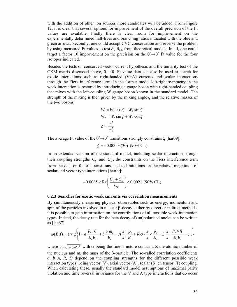
Besides the tests on conserved vector current hypothesis and the unitarity test of the CKM matrix discussed above, 0+→0+ Ft value data can also be used to search for exotic interactions such as right-handed (V+A) currents and scalar interactions through the Fierz interference term. In the former model left-right symmetry in the weak interaction is restored by introducing a gauge boson with right-handed coupling that mixes with the left-coupling W gauge boson known in the standard model. The strength of the mixing is then given by the mixing angle ζ and the relative masses of the two bosons:
22
21
2
1
cossinsincos
mm
WWWWWW
RL
RL
=
+=−=
δ
ζζζζ
The average Ft value of the 0+→0+ transitions strongly constrains ζ [har09]:
0.00003(30)ζ = − (90% CL).
In an extended version of the standard model, including scalar interactions trough their coupling strengths SC and '
SC , the constraints on the Fierz interference term from the data on 0+→0+ transitions lead to limitations on the relative magnitude of scalar and vector type interactions [har09]:
'
0.0065 Re 0.0021⎛ ⎞+
− < <⎜ ⎟⎝ ⎠
S S
V
C CC
(90% CL).
6.2.3 34B36BSearches for exotic weak currents via correlation measurements By simultaneously measuring physical observables such as energy, momentum and spin of the particles involved in nuclear β-decay, either by direct or indirect methods, it is possible to gain information on the contributions of all possible weak-interaction types. Indeed, the decay rate for the beta decay of (un)polarised nuclei can be written as [jac67]:
⎭⎬⎫
⎩⎨⎧
+×
⋅+×⋅+⋅++⋅
+∝Ω K
rrrrrrrrr
νν
σγξωEE
qpJJD
Ep
JJR
Ep
JJA
Emb
EEqp
aEe
e
e
e
e
e
e
e
e
e 1,...),(
where 2)(1 Zαγ −= with α being the fine structure constant, Z the atomic number of the nucleus and me the mass of the β-particle. The so-called correlation coefficients a, b A, R, D depend on the coupling strengths for the different possible weak interaction types, being vector (V), axial vector (A), scalar (S) en tensor (T) coupling. When calculating these, usually the standard model assumptions of maximal parity violation and time reversal invariance for the V and A type interactions that do occur

37
in the standard model are made. Because of the transformation properties of the different interaction types it then turns out that Fermi β-transitions are sensitive to V and S couplings whereas Gamow-Teller decay is sensitive to A and T interactions. It may also be noted here that in most correlation experiments the Fierz interference term is present, such that the effective coupling terms can be written as :
),,(with 1
~KAaX
Emb
XX
e
e=
+=
γ
The quantities that can be determined in correlation experiments are the nuclear spin polarization /
rJ J , the energy eE , momentum epr and spin polarization σ of the beta
particle and, finally, the energy νE and momentum of the neutrino qr . The latter two are determined indirectly through observation of the recoil of the decaying nucleus.
The β-neutrino correlation parameter a, which is the first term in the decay rate formula mentioned above, is sensitive to non-standard model coupling types in a quadratic way. However, it has the advantage that it is independent of possible counteracting contributions of iC and '
iC . The values of the correlation coefficient a for pure Fermi and Gamow-Teller transitions are:
2
2'2
1V
SSF
C
CCa
+−≅
⎥⎥
⎦
⎤
⎢⎢
⎣
⎡ +−−≅ 2
2'2
131
A
TTGT
C
CCa
In this correlation the β- and the neutrino momentum vector are measured. Since the neutrino is difficult to detect, its energy and emission direction are determined indirectly by measuring the recoil of the daughter nucleus in the decay. A schematic drawing is presented in Figure 13.
Figure 13. Schematic drawing of the beta-neutrino correlation. In order to do so, it is crucial that a source with little or no backing material is made because the trajectory of a recoiling nucleus is easily disturbed. For this purpose, ion traps are used. The radioactive ions are confined in a small volume by means of electromagnetic fields (Penning and Paul traps) or via the interaction with an appropriate laser beam (Magneto Optical Trap trap) (see Figure 14).

38
Figure 14. Ion traps used in weak interaction studies.
In open trap structures such as Paul or MOT traps, the flight of the recoil nucleus is very little disturbed and direct measurement can be done by a time of flight method where the β-particle acts as a start signal [sci04]. In the case of a Penning trap where the radial confinement of the ions is achieved by using a strong magnetic field, one can still measure the recoil ion energy spectrum shape by means of a retardation spectrometer [bec03]. An alternative way of detecting the energy of the recoil nucleus is by measuring the Doppler broadening of a subsequent decay, mostly a γ-transition. Because of the small recoil energy the shift would be rather small so a precise measurement of the γ-energy is required. This is feasible by means of a bent crystal spectrometer in which very high energy resolutions can be achieved albeit with a rather poor detection efficiency. In a facility like ISOL@MYRRHA where high production rates of the radioisotopes are expected, this statistics limitation problem could be overcome.
Since a few years, several β-neutrino correlation measurements are being undertaken at various facilities over the world [sci04,bec03]. Current limits, particularly on a possible scalar type weak interaction, are rather weak and do allow a contribution relative to the standard model vector type coupling of close to 10 % [sev06]. It is clear that in this field there is certainly significant room for improvement on these constraints.
The β asymmetry parameter A also carries information on new coupling types in the weak interaction albeit indirectly through the so-called recoil terms. Moreover, only for tensor type coupling information can be obtained in an unambiguous way because the asymmetry parameter for allowed Fermi transitions, to which possible scalar coupling could contribute, is zero. In these experiments one measures the emission probability W(θ) of the β-particles with momentum rep and energy Ee relative to the
nuclear polarisation vector /rJ J :
( ) 1θ = + ⋅ %
e
J pW AJ E
.
For pure Gamow-Teller transitions the asymmetry parameter is given by:
⎥⎥⎦
⎤
⎢⎢⎣
⎡⎟⎟⎠
⎞⎜⎜⎝
⎛ ++⎟⎟
⎠
⎞⎜⎜⎝
⎛ ++≅
A
TT
e
e
A
TTeJJGT C
CCEm
CCC
pZm
A''
' ReIm1~ γαλβ m
m
,
where λJ’J is a spin dependent factor. The last term in the equation originates from the Fierz interference term b. The second term in the square brackets is known to be small from an R-correlation experiment that was performed on 8Li (-0.008<Im[(CT+
Penning MOT
Paul
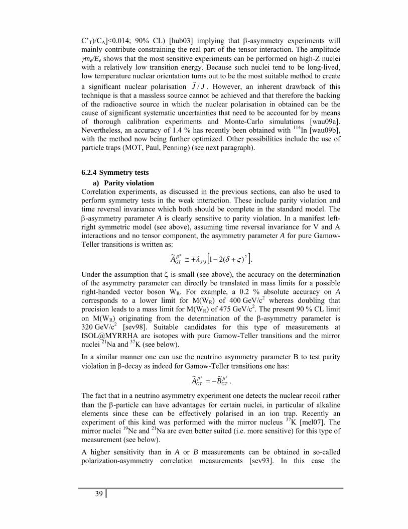
39
C’T)/CA]<0.014; 90% CL) [hub03] implying that β-asymmetry experiments will mainly contribute constraining the real part of the tensor interaction. The amplitude γme/Ee shows that the most sensitive experiments can be performed on high-Z nuclei with a relatively low transition energy. Because such nuclei tend to be long-lived, low temperature nuclear orientation turns out to be the most suitable method to create a significant nuclear polarisation /
rJ J . However, an inherent drawback of this
technique is that a massless source cannot be achieved and that therefore the backing of the radioactive source in which the nuclear polarisation in obtained can be the cause of significant systematic uncertainties that need to be accounted for by means of thorough calibration experiments and Monte-Carlo simulations [wau09a]. Nevertheless, an accuracy of 1.4 % has recently been obtained with 114In [wau09b], with the method now being further optimized. Other possibilities include the use of particle traps (MOT, Paul, Penning) (see next paragraph).
6.2.4 35B37BSymmetry tests a) Parity violation
Correlation experiments, as discussed in the previous sections, can also be used to perform symmetry tests in the weak interaction. These include parity violation and time reversal invariance which both should be complete in the standard model. The β-asymmetry parameter A is clearly sensitive to parity violation. In a manifest left-right symmetric model (see above), assuming time reversal invariance for V and A interactions and no tensor component, the asymmetry parameter A for pure Gamow-Teller transitions is written as:
[ ]2' )(21~ ςδλβ +−≅ JJGTA m
m
.
Under the assumption that ζ is small (see above), the accuracy on the determination of the asymmetry parameter can directly be translated in mass limits for a possible right-handed vector boson WR. For example, a 0.2 % absolute accuracy on A corresponds to a lower limit for M(WR) of 400 GeV/c2 whereas doubling that precision leads to a mass limit for M(WR) of 475 GeV/c2. The present 90 % CL limit on M(WR) originating from the determination of the β-asymmetry parameter is 320 GeV/c2 [sev98]. Suitable candidates for this type of measurements at ISOL@MYRRHA are isotopes with pure Gamow-Teller transitions and the mirror nuclei 21Na and 37K (see below).
In a similar manner one can use the neutrino asymmetry parameter B to test parity violation in β-decay as indeed for Gamow-Teller transitions one has:
mm ββGTGT BA ~~
−= .
The fact that in a neutrino asymmetry experiment one detects the nuclear recoil rather than the β-particle can have advantages for certain nuclei, in particular of alkaline elements since these can be effectively polarised in an ion trap. Recently an experiment of this kind was performed with the mirror nucleus 37K [mel07]. The mirror nuclei 19Ne and 21Na are even better suited (i.e. more sensitive) for this type of measurement (see below).
A higher sensitivity than in A or B measurements can be obtained in so-called polarization-asymmetry correlation measurements [sev93]. In this case the
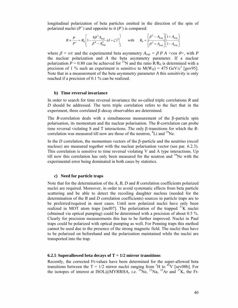
40
longitudinal polarization of beta particles emitted in the direction of the spin of polarized nuclei (P+) and opposite to it (P-) is compared:
22_ exp expexp 20 04 2 2
exp exp exp
181 ( ) with
1
A AAPR R RP A A A
ββδ ζ
β β+
⎡ ⎤ ⎡ ⎤− +⎡ ⎤ ⎣ ⎦⎣ ⎦⎢ ⎥≡ = − + =⎡ ⎤− ⎡ ⎤⎢ ⎥ + −⎣ ⎦ ⎣ ⎦⎣ ⎦
where β = v/c and the experimental beta asymmetry Aexp = β P A <cos θ>, with P the nuclear polarization and A the beta asymmetry parameter. If a nuclear polarization P = 0.80 can be achieved for 21N and the ratio R/R0 is determined with a precision of 1 % such an experiment is sensitive to M(WR) = 475 GeV/c2 [gov95]. Note that in a measurement of the beta asymmetry parameter A this sensitivity is only reached if a precision of 0.1 % can be realized.
b) Time reversal invariance
In order to search for time reversal invariance the so-called triple correlations R and D should be addressed. The term triple correlation refers to the fact that in the experiment, three correlated β-decay observables are determined.
The R-correlation deals with a simultaneous measurement of the β-particle spin polarisation, its momentum and the nuclear polarisation. The R-correlation can probe time reversal violating S and T interactions. The only β-transitions for which the R-correlation was measured till now are those of the neutron, 8Li and 19Ne.
In the D correlation, the momentum vectors of the β-particle and the neutrino (recoil nucleus) are measured together with the nuclear polarisation vector (see par. 6.2.3). This correlation is sensitive to time reversal violating V and A type interactions. Up till now this correlation has only been measured for the neutron and 19Ne with the experimental error being dominated in both cases by statistics.
c) Need for particle traps
Note that for the determination of the A, B, D and R correlation coefficients polarized nuclei are required. Moreover, in order to avoid systematic effects from beta particle scattering and be able to detect the recoiling daughter nucleus (needed for the determination of the B and D correlation coefficients) sources in particle traps are to be preferred/required in most cases. Until now polarized nuclei have only been realized in MOT atom traps [mel07]. The polarization of the trapped 37K nuclei (obtained via optical pumping) could be determined with a precision of about 0.5 %. Clearly for precision measurements this has to be further improved. Nuclei in Paul traps could be polarized with optical pumping as well. For Penning traps this method cannot be used due to the presence of the strong magnetic field. The nuclei thus have to be polarized on beforehand and the polarization maintained while the nuclei are transported into the trap.
6.2.5 36B38BSuperallowed beta decays of T = 1/2 mirror transitions Recently, the corrected Ft-values have been determined for the super-allowed beta transitions between the T = 1/2 mirror nuclei ranging from 3H to 45V [sev08b]. For the isotopes of interest at ISOL@MYRRHA, i.e. 19Ne, 21Na, 35Ar and 37K, the Ft-
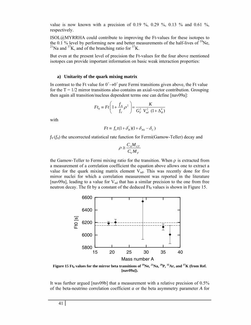
41
value is now known with a precision of 0.19 %, 0.29 %, 0.13 % and 0.61 %, respectively.
ISOL@MYRRHA could contribute to improving the Ft-values for these isotopes to the 0.1 % level by performing new and better measurements of the half-lives of 19Ne, 21Na and 37K, and of the branching ratio for 37K.
But even at the present level of precision the Ft-values for the four above mentioned isotopes can provide important information on basic weak interaction properties:
a) Unitarity of the quark mixing matrix
In contrast to the Ft value for 0+→0+ pure Fermi transitions given above, the Ft value for the T = 1/2 mirror transitions also contains an axial-vector contribution. Grouping then again all transition/nucleus dependent terms one can define [nav09a]:
20 2 21
(1 )A
VV F ud R
f KFt Ftf G Vρ
⎛ ⎞≡ + =⎜ ⎟ + Δ⎝ ⎠
with '(1 )(1 )V R NS CFt f t δ δ δ≡ + + −
fV (fA) the uncorrected statistical rate function for Fermi(Gamow-Teller) decay and
A GT
V F
C MC M
ρ ≅
the Gamow-Teller to Fermi mixing ratio for the transition. When ρ is extracted from a measurement of a correlation coefficient the equation above allows one to extract a value for the quark mixing matrix element Vud. This was recently done for five mirror nuclei for which a correlation measurement was reported in the literature [nav09a], leading to a value for Vud that has a similar precision to the one from free neutron decay. The fit by a constant of the deduced Ft0 values is shown in Figure 15.
5800
6000
6200
6400
6600
15 20 25 30 35 40
Ft0
[s]
Mass number A Figure 15 Ft0 values for the mirror beta transitions of 19Ne, 21Na, 29P, 35Ar, and 37K (from Ref.
[nav09a]).
It was further argued [nav09b] that a measurement with a relative precision of 0.5% of the beta-neutrino correlation coefficient a or the beta asymmetry parameter A for
42
19Ne, or of the beta asymmetry parameter A for 35Ar, would yield a value for Vud with an absolute precision of 14 x 10-4 (19Ne), resp. 7 x 10⁻⁴ (35Ar) with the present Ft-values. If these two values can be improved to the level of 5 x 10⁻⁴ or better, the error on the value for Vud does depend only on the precision of the correlation coefficient and absolute precisions of 10 x 10-4 (19Ne), resp. 4 x 10⁻⁴ (35Ar) are obtained. Note that the current precision on Vud from all data for the set of 0+→0+ pure Fermi transitions is only about a factor 2 better, i.e. 2.2 x 10⁻⁴, underlying the high sensitivity to Vud in correlation measurements of mirror nuclei.
b) Scalar and tensor currents
The sensitivity to exotic currents in correlation measurements on the super-allowed beta decays of the mirror nuclei up to 41Sc was recently investigated [tan06]. Of the four isotopes of interest to ISOL@MYRRHA, measurements of the beta-neutrino correlation coefficient a, the beta asymmetry parameter A and the neutrino asymmetry parameter B for 35Ar and 37K as well as the beta-neutrino correlation coefficient a for 21Na all turned out to be quite sensitive to scalar charged weak currents. The standard model values for all these correlation coefficients were calculated in Ref. [sev08b].
c) Parity violation
The sensitivity of the mirror beta transitions to the existence of V+A charged weak currents (i.e. testing maximal violation of parity) was discussed already in Ref. [nav91] (see also par. 6.2.4). From the standard model values for the A and B correlation coefficients (see Table X in Ref. [sev08b]), it turns out that a measurement of A for 21Na and of B for 19Ne and 21Na are to be preferred as for these the systematic error contribution from the corrected Ft values is minimal.
d) Time reversal invariance
With the corrected Ft values now being known for the mirror beta transitions the final state effects for measurements of the R-triple correlation are known with good precision (Table X in Ref. [sev08b]) so that precise time reversal violations tests - in search for time reversal violating charged scalar or tensor weak currents - with 19Ne, 21Na, 35Ar and 37K are in principle also possible at ISOL@MYRRHA.
6.2.6 Symmetry tests in neutral atoms Also by performing high-precision measurements on atoms with high atomic number Z, symmetries can be tested in the electroweak interaction. High-Z atoms are more sensitive to possible new short-ranged interactions between leptons and quarks, because the overlap of electrons with the nucleus is larger. Beams from ISOL@MYRRHA would allow exploring these possibilities using state-of-the-art atomic experimental techniques. An obvious program would be the study of time reversal violation by measuring the electric dipole moment (EDM) of atoms like radium. Another possibility would be atomic parity non-conservation (APNC) experiments with francium atoms.

43
a) Time reversal violation: electric dipole moment of radium Because the electric dipole moment (EDM) violates parity and time reversal, it constitutes a model-independent observable to new sources of CP/T violation. Permanent EDMs, corresponding to sources of CP violation much larger than the one included in the standard model, would shed more light on the as yet unexplained difference between the amount of matter and antimatter in the universe. As there exist many possible theoretical scenarios for CP violation beyond the standard model, EDMs can show up differently in different systems. The discovery potential can thus be maximized by experimentally probing different systems. For 223Rn (experiment in preparation at TRIUMF) and 225Ra (experiments in preparation at Argonne National Lab and at KVI-Groningen, using a MOT [wil08]) large enhancement factors are expected due to almost degenerate opposite parity states and nuclear-structure effects (octupole deformation), both leading to a large amplification of the sensitivity to CP violation effects.
b) Atomic parity non-conservation in francium APNC experiments have recently reached a level of precision to provide strong constraints on new physics beyond the standard model. There is strong interest in francium (Fr) isotopes for such measurements, because the APNC effect increases faster than Z3 and francium is the heaviest atom with a simple atomic structure, i.e., with a single S electron outside a noble-gas core. The prediction of the APNC effect for Fr is 18 times larger than for cesium, the heaviest of the stable alkali atoms, for which a very precise measurement of the APNC effect was already performed, resulting in perfect agreement with atomic theory. Like the EDM of radium, APNC of Fr can be studied in a MOT. Uncertainties in atomic structure and the dependence on the atomic theory contribution can be minimized and/or eliminated by performing measurements along a chain of isotopes.
6.2.7 General conclusion The general conclusion for this type of experiments is that they require a high precision and accuracy. This means that long measuring times and high intensities are needed to gain sufficient statistics but also that a very good knowledge of the experimental apparatus must be obtained to master systematic effects. Consequently, sufficient time must be allocated to perform set-up calibration experiments that in many cases will also demand the use of radioactive beams from the ISOL@MYRRHA facility.
6.3 Solid-state physics
6.3.1 37B39B
8Li β-NMR A significant fraction of solid-state physics research is nowadays dealing with the study of physical phenomena occurring when the system size is comparable to a relevant physical length scale, for instance the magnetic penetration depth and the coherence length for superconductors, the domain size and exchange interaction lengths in magnetic systems, the electronic mean free path, etc. Most of these length scales are of the order of a few nanometer up to a few hundred of nanometer. These mesoscopic effects are therefore very pronounced in thin films and nanostructured materials. The progress in applications (especially in the electronics industry) is

44
firmly rooted in fundamental studies of such nanostructured materials. For instance the miniaturization of hard-disk drives finds its origin in the discovery of the giant magneto-resistance effect in multilayered stacks of magnetic and non-magnetic films with a layer thickness of the order of a few nanometers.
One of the key features in understanding the physics of nanostructured materials is to have microscopic information about the local electric and magnetic field within the sample. Very often these fields may vary significantly as function of the depth within the sample, for instance. A number of experimental methods are available to study the magnetic depth profile within a sample, the most important of which are polarized neutron reflectivity [fit04], synchrotron based nuclear resonant scattering and resonant X-ray scattering [sra06], muon spin rotation [mor01] and β-Nuclear Magnetic Resonance (β-NMR) [cho03].
Determining the magnetic depth profile is crucial for getting an understanding of the physics of thin magnetic and superconducting films. In the following the currently available methods will be briefly discussed, each with their particular advantages and disadvantages.
Polarized neutron reflectivity allows the determination of the magnetic depth profile with nanometer resolution. The drawback of the technique is that it requires samples with a superior surface finish: surface roughness will deteriorate the sample’s reflectivity and, hence, the ability to measure a meaningful reflectivity pattern from which the magnetic depth profile can be reconstructed. A second limitation is that the available neutron flux at neutron facilities is relatively small, although a significant progress can be expected with the introduction of new-generation spallation neutron sources.
Magnetic resonant scattering of soft X-rays is a fast-developing synchrotron-based technique which also achieves nanometer depth resolution. Its main limitation is that the absorption edge of the materials embedded within the sample should be accessible for the monochromator used at the setup. On the other hand, this limitation is outweighed by the ever increasing photon fluxes available at third-generation synchrotron sources.
Nuclear resonant scattering is basically the time-domain analogue of classical Mossbauer spectroscopy. It is based on the excitation of suitable nuclei by a synchrotron beam. The time evolution of the decay of the excited states delivers information on the local hyperfine field. This is a very powerful technique, but its obvious limitation is the fact that it only operates using a still limited number of suitable Mossbauer isotopes. It also puts very severe constraints on the monochromator that is used. So far, only three beam lines are worldwide available for this technique.
Muon spin rotation is based on the precession of the muon due to the local magnetic field. The penetration depth of muons is typically of the order of a few millimeters, making the method best suited for the study of bulk materials. Thin films can be probed with low-energy muon implantation, but in that case a very significant fraction of the initial beam intensity is lost in the moderation process.
In β-NMR, a polarized radioactive beam (e.g., 8Li) is implanted in the sample. The implantation depth is controlled by varying the electrostatic potential on the sample, which defines the beam energy. This technique has several analogies with muon spin rotation, but since the lifetime of the probes is different, the field ranges that can be
45
measured are also different. Since several years, β-NMR is used very successfully for condensed-matter studies at the TRIUMF facility in Vancouver [cho03,xu08]. A striking example has been the determination of the sites that Li occupies in non-magnetic silver [mor04b] and copper [sal07a] films. β-NMR has also been used to determine very precisely the depth profile of the magnetic field in ferromagnetic films and multilayers, e.g., a nearly ferromagnetic Pd film [par07] and a Ag/Fe multilayer [kee08]. In these examples, an almost unprecedented depth sensitivity was achieved. It was also employed for studies of the vortex lattice in superconducting NbSe2 films, where it turned out to be possible to determine the size of the vortex core as a function of magnetic field [sal07b]. It should be noted that - apart from very complicated tunnelling-spectroscopy studies using a low-temperature scanning tunneling microscope – there are virtually no other methods giving access to this information. From these selected examples it should be clear that β-NMR provides access to a number of very relevant parameters in low-dimensional systems that are at the heart of contemporary solid-state physics.
The short comparison above shows that each technique has a number of specific advantages and disadvantages. There is no single technique that can provide all information on magnetic depth profile, magnitude of the local field, direction of the field, magnetization reversal mechanism, static and dynamic properties, etc. For that reason, a single sample is often studied using a number of complementary techniques. During the past decades the number of research topics involving a precise determination of local magnetic fields has steadily increased. The result is that many of the above mentioned facilities are (heavily) oversubscribed. There is absolutely a demand for more beam time and available facilities. The availability of a polarized 8Li beam at ISOL@MYRRHA would therefore constitute a unique opportunity to capitalize on the MYRRHA investment and to build a world-class solid-state physics research setup. Initially the aim should be to get at least on a par with the β-NMR facility at TRIUMF in Vancouver, possibly better. In order to achieve this, a more intense and maximally polarized 8Li beam should be prepared and progress can also be made with respect to the sample facility. This should be envisaged as complete as it has been done at several synchrotron sources, i.e. an online ultra-high vacuum system in which the films can be prepared and measured in situ, including samples being subjected to extreme temperatures and fields.
As applications for a β-NMR facility at ISOL@MYRRHA it would be highly desirable to study for instance thin films of multiferroic materials, in which the aim is to have an electric control over the magnetic state; the structural and magnetic properties of diluted magnetic semiconductors; hybrid ferromagnet/superconductor systems; ferromagnet/antiferromagnet exchange bias and exchange spring systems; spin glass layers; metal/organic hybrid layers and functionalized nanoparticles which have important potential for applications in drug delivery and cancer treatment and many others.
6.3.2 38B40BEmission channeling
The presence of impurity atoms can drastically change the electrical, magnetic and optical properties of semiconductors. This can be used with the intention to dope such materials, by which one can control the electrical resistivity, the magnetization or the luminescence. On the other hand, impurity atoms can also be present unintentionally and in this way they can damage the performance of electronic

46
devices. To understand the effect of impurities on the properties of the material it is important to know the exact lattice location (in other words the local crystal field) of these impurities, and how the lattice site depends on the presence of defects in the semiconductor. Whereas methods such as infrared spectroscopy, photoluminescence spectroscopy, X-ray absorption fine structure or electron paramagnetic resonance characterize the local symmetry surrounding the impurity (hence providing indirect information on the lattice site), approaches relying on the channeling of charged particles provide direct information on the lattice site of impurity atoms.
A well-established technique in that respect is ion beam channeling, which has been used in material analysis for several decades [tes95]. In ion beam channeling, an energetic, light ion beam – typically MeV He ions – is impinging along a major symmetry direction (lattice axis or lattice plane) of a single crystalline host, drastically reducing the probability for a close encounter collision between the incoming ion and the host atoms. From angular scan measurements (i.e. measuring the backscattering yield as a function of angle of incidence) along at least two directions, the lattice site of impurity atoms can be determined. On the other hand, radioactive probe atoms – acting as emitters of (conversion) electrons, positrons, or α particles – can be implanted in the single crystalline host. During the subsequent decay, the emitted charged particles can undergo a similar channeling and blocking effect as described above, resulting in anisotropic emission patterns. In this so-called emission channeling technique [hof91], the yield of charged particles emitted from the radioactive impurity atoms inside the sample is recorded with a two-dimensional position sensitive detector for different emission directions around major crystallographic axes and planes, where channeling or blocking effects are experienced. The sensitivity of emission channeling (with electron and positron particles) can be up to four orders of magnitude higher than in conventional lattice location experiments using ion beam channeling. The reason is twofold : (i) by using radioactive probes, the required number of probe atoms can be much lower than with ion beam channeling methods; and (ii) the use of 2D-detectors with large solid angles further increases the detection efficiency [wah04]. Moreover, direct information can be obtained on the lattice sites of impurities in single crystals with a precision that can be below 0.1 Å, which is significantly better than can be achieved with ion beam channeling. Finally, since no host signal is recorded during an emission channeling experiment, this technique allows investigating low concentrations of light impurities in a heavy host, in contrast to ion beam channeling. Hence, emission channeling is very well-suited to study systems where conventional ion beam techniques cannot be applied due to a lack of sensitivity and/or precision.
To study the interaction of defects with probe atoms, the emission channeling technique can be combined with nuclear hyperfine interaction techniques, such as perturbed angular correlation (PAC) or Mössbauer spectroscopy (MS) under identical or very similar experimental conditions. While emission channeling provides information on the lattice position of the probe atoms, PAC and MS allow the characterization of specific impurity/defect pairs by measuring quantities like electric field gradients, local magnetic fields and isomer shifts at the sites of probe atoms.
With the advent of ISOL facilities, ISOLDE in particular, emission channeling experiments can profit from the wide choice of suitable radioactive probe isotopes available that could be implanted into the matrix under investigation. Important criteria for isotopes are:

47
• Decay half-life: T1/2 < several months; • Energy of emitted particles above X-ray background: E > ~20 keV; • No superposition from decay chains or one which can easily be disentangled; • Radiation protection issues; • Sufficient RIB yield: >106 ions/s.
For some elements, however, there is no suitable isotope that simultaneously meets all criteria listed above. Facilities providing higher RIB yields, like HIE-ISOLDE (~10-μA primary beam intensity) in the near future and EURISOL (~100-μA primary beam intensity) on the longer term, will extend the list of suitable isotopes and several new probe elements, e.g. 27Mg, 31Si, 33P, 35S, 65Ni and 75Ge will become available.
Compared to EURISOL, the list of suitable isotopes for performing emission channeling measurements will be similar at ISOL@MYRRHA, where beams with high intensity and selectivity will be available as well. Besides the availability of radioactive probe atoms, both long and frequent beam access is also important for systematic sample investigations. Two illustrative examples are:
• Probing the evolution of lattice sites as a function of annealing temperature or as a function of implanted fluence: during conventional beam times, only about five annealing temperatures can typically be measured, see e.g. Ref. [dec09].
• Properties of co-doped semiconductors require a detailed investigation as a function of doping concentration, doping species, temperature, etc…
In case of the longer-lived probe atoms that will be measured off-line, the frequent access to short beam times (in the order of one 8-hour shift) is of critical importance for systematic investigations. A compromise has to be made between the number of samples that can be measured during 4-5 half-lives (taking into account the limited number of detection set-ups) and the number of parameters to be varied. In case of on-line measurements with short-lived probe atoms, it is the available beam time length which is crucial in order to perform detailed systematic studies. The long beam times of several weeks or more at ISOL@MYRRHA and frequent short beam times will significantly enhance such systematic studies.
6.4 21B23BNuclear Physics Since no post-acceleration is foreseen in the first phase at ISOL@MYRRHA, nuclear-physics investigations will be more or less restricted to decay studies involving small signals (e.g., small decay branches), high-precision measurements and/or experiments with an inherent limited detection efficiency. In the following, the focus will be on β-decay and β-delayed particle decay studies over other decays (e.g., two-proton decay). In particular, systematic measurements of β-delayed neutron probabilities Pn are of special interest in nuclear astro-physics to model the nuclear paths of the rapid-neutron process, as well as in nuclear applications as nuclear-reactor control and non-destructive characterization of nuclear waste. The required equipment will consist of a passive or active stopper, or a trap catching the radioactive ion to be investigated, and detectors for β, γ, charged particles and neutrons.

48
In the first section, the interest in nuclear-physics experiments with high precision, small signals, or inherent limited efficiencies is motivated in general terms. In the second section, the specific case of 14Be decay, a possible candidate for such studies, will be discussed as an illustration of the unique possibilities at ISOL@MYRRHA. It is realized that the estimated production yield of 14Be is only of the order of the current PSB production yield at ISOLDE due to the lower primary-beam energy of 600 MeV. With the capability to upgrade to 1 GeV, however, the 14Be intensity will be competitive with the estimated yield at the future EURISOL facility on top of the long beam times.
6.4.1 39B41BMotivation for high-precision, small-signal and/or low-efficiency experiments
Allowed β-decay is a selective process affording a direct measure of the difference between the initial and final wave functions. As such, the Gamow-Teller strength B(GT) distribution in a nucleus provides an important test of structure calculations for that nucleus. A major part of the B(GT) strength, however, is situated in the Gamow-Teller Giant Resonance (GTGR), which is normally at energies inaccessible from β-decay, except for nuclei far from stability where β-endpoint energies Qβ become largest. Although β-transitions to the GTGR have a large B(GT) strength, the corresponding β-branching ratios are small as a consequence of the small phase-space factor f. Close to the drip line, where Qβ values are large and particle separation energies are small, β-delayed particle emission becomes energetically allowed and as such a direct and important probe for obtaining B(GT) strength distributions.
When multi-particle decays occur (e.g., βxn, βxp, βpn), one of the key questions concerns the particle emission mechanism that is involved. This can be investigated by measuring the correlation between the decaying particles. So far, only the β2p correlation in 31Ar decay has been studied, where a sequential emission of the two protons was observed [fyn00]. More recently, even β3p has been observed for the first time in 45Fe [mie07]. Information on β2n decays is limited. The β-delayed multi-particle process is, however, energetically allowed in many nuclei and should occur in many more than the presently known emitters [jon01], see Figure 16.
Figure 16 Nuclei with N,Z<=50 for which the Q-value for various β-delayed particle emission processes is positive [jon01]. To the left single- and multi-nucleon emission, to the right emission of nuclei of mass number 2 and 3. The Q-values were calculated from Ref. [aud97].
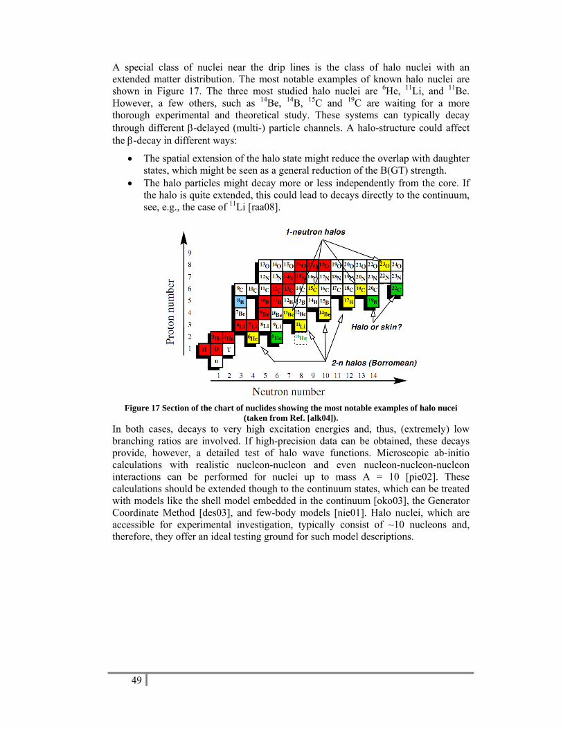
49
A special class of nuclei near the drip lines is the class of halo nuclei with an extended matter distribution. The most notable examples of known halo nuclei are shown in Figure 17. The three most studied halo nuclei are 6He, 11Li, and 11Be. However, a few others, such as 14Be, 14B, 15C and 19C are waiting for a more thorough experimental and theoretical study. These systems can typically decay through different β-delayed (multi-) particle channels. A halo-structure could affect the β-decay in different ways:
• The spatial extension of the halo state might reduce the overlap with daughter states, which might be seen as a general reduction of the B(GT) strength.
• The halo particles might decay more or less independently from the core. If the halo is quite extended, this could lead to decays directly to the continuum, see, e.g., the case of 11Li [raa08].
Figure 17 Section of the chart of nuclides showing the most notable examples of halo nucei
(taken from Ref. [alk04]). In both cases, decays to very high excitation energies and, thus, (extremely) low branching ratios are involved. If high-precision data can be obtained, these decays provide, however, a detailed test of halo wave functions. Microscopic ab-initio calculations with realistic nucleon-nucleon and even nucleon-nucleon-nucleon interactions can be performed for nuclei up to mass A = 10 [pie02]. These calculations should be extended though to the continuum states, which can be treated with models like the shell model embedded in the continuum [oko03], the Generator Coordinate Method [des03], and few-body models [nie01]. Halo nuclei, which are accessible for experimental investigation, typically consist of ~10 nucleons and, therefore, they offer an ideal testing ground for such model descriptions.

50
Figure 18 Comparison between the experimental data and the best fit obtained by Monte Carlo simulations on the left [sar04]. For transitions involving the (1-,22
+) doublet, all contributions are shown. The deduced 11Li β-delayed neutron decay scheme is shown on the right. Measuring the line shape of gamma transitions after β-delayed particle decay allows for the determination of energies and relative intensities of all the particle branches feeding, directly or indirectly, the state from which the γ transition arises, of the half-life of the excited state, and eventually of other resonance parameters. Especially in the light nuclei, the broadening effects are large. A recent example is the β-delayed neutron decay study of 11Li [sar04,mat09], where both the half-lives of states in 10Be and the energies of the β-delayed neutrons feeding those states were obtained from a line-shape analysis of the Doppler-broadened peaks observed in the 10Be γ spectrum. The complex shape of the γ lines, see Figure 18, could be analyzed by a Monte Carlo simulation. Relative intensities could be determined to a factor 2-5 more precise as compared to other experiments using β-γ and β-n-γ coincidences, see references in Ref. [sar04], The data suggested that the β decay to the 8.81 MeV state in 11Be occurs in the 9Li core and that one neutron comprising the halo of 11Li survives in a halo-like configuration after the β-delayed neutron emission from this level. Nevertheless, the precision of the line-shape analysis is limited by the inherent photo-peak energy resolution of the HPGe detectors. In addition, a systematic error of ~10% has to be taken into account for the deduced half-life values originating from the recoil-energy loss of 10Be in the aluminium implantation tape. Both effects prohibit more precise experimental information. Moreover, in this specific case of the 11Li decay, the photo-peak resolution of the HPGe detectors is not sufficient to resolve the γ peaks originating from the 5961- and 5958-keV levels (see peaks in upper left and lower right panels of Figure 18), which complicated the analysis drastically. The systematic error of 10% can be avoided by using, e.g., an ion trap for backing-free recoil. In the case of a Penning ion trap, the selectivity of the RIB can be further enhanced by inducing selective excitations. A more precise determination of the line shape can in principle be obtained by using a γ-ray crystal spectrometer, which allows γ-ray energy resolutions down to the part per million precision [des80] in the energy domain 0.1-6 MeV.
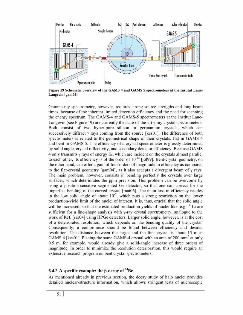
51
Figure 19 Schematic overview of the GAMS 4 and GAMS 5 spectrometers at the Institut Laue-Langevin [gam04].
Gamma-ray spectrometry, however, requires strong source strengths and long beam times, because of the inherent limited detection efficiency and the need for scanning the energy spectrum. The GAMS-4 and GAMS-5 spectrometers at the Institut Laue-Langevin (see Figure 19) are currently the state-of-the-art γ-ray crystal spectrometers. Both consist of two hyper-pure silicon or germanium crystals, which can successively diffract γ rays coming from the source [kes01]. The difference of both spectrometers is related to the geometrical shape of their crystals: flat in GAMS 4 and bent in GAMS 5. The efficiency of a crystal spectrometer is grossly determined by solid angle, crystal reflectivity, and secondary detector efficiency. Because GAMS 4 only transmits γ rays of energy E0, which are incident on the crystals almost parallel to each other, its efficiency is of the order of 10-12 [jol99]. Bent-crystal geometry, on the other hand, can offer a gain of four orders of magnitude in efficiency as compared to the flat-crystal geometry [gam04], as it also accepts a divergent beam of γ rays. The main problem, however, consists in bending perfectly the crystals over large surfaces, which deteriorates the ppm precision. This problem can be overcome by using a position-sensitive segmented Ge detector, so that one can correct for the imperfect bending of the curved crystal [mat06]. The main loss in efficiency resides in the low solid angle of about 10-7, which puts a strong restriction on the lower production-yield limit of the nuclei of interest. It is, thus, crucial that the solid angle will be increased, so that the estimated production yields of nuclei like, e.g., 11Li are sufficient for a line-shape analysis with γ-ray crystal spectrometry, analogue to the work of Ref. [sar04] using HPGe detectors. Larger solid angle, however, is at the cost of a deteriorated resolution, which depends on the bending quality of the crystal. Consequently, a compromise should be found between efficiency and desired resolution. The distance between the target and the first crystal is about 15 m at GAMS 4 [kes01]. Placing the same GAMS-4 crystal with an area of 200 mm2 at only 0.5 m, for example, would already give a solid-angle increase of three orders of magnitude. In order to minimize the resolution deterioration, this would require an extensive research program on bent crystal spectrometers.
6.4.2 40B42BA specific example: the β decay of 14Be As mentioned already in previous section, the decay study of halo nuclei provides detailed nuclear-structure information, which allows stringent tests of microscopic
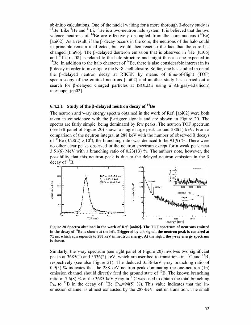
52
ab-initio calculations. One of the nuclei waiting for a more thorough β-decay study is 14Be. Like 6He and 11Li, 14Be is a two-neutron halo system. It is believed that the two valence neutrons of 14Be are effectively decoupled from the core nucleus (12Be) [aoi02]. As a result, if the β decay occurs in the core, the neutrons of the halo could in principle remain unaffected, but would then react to the fact that the core has changed [tim96]. The β-delayed deuteron emission that is observed in 6He [tur06] and 11Li [raa08] is related to the halo structure and might thus also be expected in 14Be. In addition to the halo character of 14Be, there is also considerable interest in its β decay in order to investigate the N=8 shell closure. So far, one has studied in detail the β-delayed neutron decay at RIKEN by means of time-of-flight (TOF) spectroscopy of the emitted neutrons [aoi02] and another study has carried out a search for β-delayed charged particles at ISOLDE using a ΔE(gas)–E(silicon) telescope [jep02].
6.4.2.1 46B48BStudy of the β-delayed neutron decay of 14Be The neutron and γ-ray energy spectra obtained in the work of Ref. [aoi02] were both taken in coincidence with the β-trigger signals and are shown in Figure 20. The spectra are fairly simple, being dominated by few peaks. The neutron TOF spectrum (see left panel of Figure 20) shows a single large peak around 288(1) keV. From a comparison of the neutron integral at 288 keV with the number of observed β decays of 14Be (3.28(2) ×106), the branching ratio was deduced to be 91(9) %. There were no other clear peaks observed in the neutron spectrum except for a weak peak near 3.51(6) MeV with a branching ratio of 0.23(13) %. The authors note, however, the possibility that this neutron peak is due to the delayed neutron emission in the β decay of 13B.
Figure 20 Spectra obtained in the work of Ref. [aoi02]. The TOF spectrum of neutrons emitted in the decay of 14Be is shown at the left. Triggered by a β signal, the neutron peak is centered at 71 ns, which corresponds to 288 keV in neutron energy. At the right, the γ-ray energy spectrum is shown. Similarly, the γ-ray spectrum (see right panel of Figure 20) involves two significant peaks at 3685(1) and 3536(2) keV, which are ascribed to transitions in 13C and 13B, respectively (see also Figure 21). The deduced 3536-keV γ-ray branching ratio of 0.9(3) % indicates that the 288-keV neutron peak dominating the one-neutron (1n) emission channel should directly feed the ground state of 13B. The known branching ratio of 7.6(8) % of the 3685-keV γ ray in 13C was used to obtain the total branching P1n to 13B in the decay of 14Be (P1n=94(5) %). This value indicates that the 1n-emission channel is almost exhausted by the 288-keV neutron transition. The small

53
log ft value of 3.68(5) for the β branch to the 1.28-MeV level in 14B is indicative for an allowed GT transition. The GT selection rule from the 0+ 14Be ground state uniquely determines the spin and parity of the final state to be 1+.
Figure 21 Decay scheme of 14Be deduced from neutron and γ-ray spectra, see Ref. [aoi02]. The β-delayed neutron study of Ref. [aoi02] provides a detailed description of the dominating 12Be-core decay to the 1+ state at 1.28 MeV in 14B and interprets the results in terms of the quenching of the N=8 shell closure. On the other hand, the energies of the β-delayed neutrons feeding, directly or indirectly, the 3536-keV level in 13B are not known and an interpretation involving the halo wave functions is lacking. The excitation energies of these neutron-decaying states in 14B could be obtained, however, by a line-shape analysis of the Doppler-broadened 3536-keV peak observed in the 13B γ spectrum, as discussed in Ref. [sar04] and previous section. In addition, information on the half-life of the 3536-keV level can be obtained and possibly, with more statistics, more γ transitions can be revealed in the 13B spectrum. Such data could pave the way for discovering states in 13B, where one neutron comprising the halo of 14Be survives in a halo-like configuration after the process of β-delayed neutron emission, similar to what is observed in the 11Li decay [sar04]. The branching ratio of 0.9(3) % of the 3536-keV peak in the 13B γ spectrum is, however, rather weak. With an estimated production yield of ~50 ions/s at the detection setup, and a γ photo-peak efficiency of 1 %, about 400 photo-peak events per day will be observed. In order to obtain statistics, comparable with those of the γ peaks in the 10Be spectrum following 11Li decay (i.e., ~2×10⁴ counts) [raa08], about 50 days of measurement would be required at ISOL@MYRRHA with a 600-MeV proton beam. As a comparison, only about 6 hours of beam time would be needed to obtain the same statistics with a 1-GeV proton beam, like is foreseen in the EURISOL project. In order to be competitive with EURISOL, the upgrade to a 1-GeV primary beam is thus crucial. Moreover, the availability of long beam times at ISOL@MYRRHA would then allow investigating the γ-peak shape with ultra-high precision by using crystal spectrometry. With an efficiency of about 10-5, 25 days of beam time would be required to achieve ~2000 counts in the 3536-keV peak.

54
6.4.2.2 47B49BStudy of the β-delayed charged-particle decay of 14Be In Figure 22, energy-loss curves for tritons, α particles and 13B recoils incident perpendicular to a detector setup are superimposed on the ΔE-E plot to identify charged particles, as obtained in the work of Ref. [jep02]. However, due to the limited resolution of the gas signal, different isotopes of the same element cannot be distinguished. Therefore, the charge-one particles, which are assumed to originate from 14Be decay, are assigned to be tritons, since deuterons are much less favoured energetically. The cuts, which could contain tritons, α particles and recoiling heavier nuclei are indicated in Figure 22. The events in cut A and C, however, were excluded in the analysis, as well as the events marked with circles. The events in the α cut, on the other hand, exhibit the same time distribution as the total sample of β particles detected during the experiment, which led to the conclusion that they arise from β particles being scattered in the gas detector.
Figure 22 The ΔE-E plot of β-suppressed data within 50 ms after proton impact on target as obtained in the work of Ref. [jep02]. Energy-loss curves and cuts for 13B recoils, α particles and tritons are shown. Events before 5 ms are indicated by a circle. Although events in the α cut correspond to β particles, an upper limit of the β-delayed α particles could be deduced with energy above 700 keV (i.e., 300 keV in Figure 22), where no α particles were observed. Normalizing to the 2.2×10⁴ observed β decays of 14Be, this results in an upper limit of B(βα) < 1.2×10⁻⁴. A similar analysis for the four observed tritons in cut B leads to a branching ratio of β-delayed tritons of 6×10⁻⁵ < B(βt) < 4×10⁻⁴. The 14 observed recoiling events translate in a branching ratio of 4×10⁻⁴ < B(βn) < 1.1×10⁻³ for β-delayed neutrons with energy in the interval from around 5.5 to 9 MeV. The uncertainty in the lower limit of 5.5 MeV is about 1 MeV and stems from the uncertainty in the large energy losses of the recoiling ions in the collection foil and the gas counter. As can be seen in Figure 23, the main part of the β strength is predicted to lie in the region a few MeV below the Qβ value. Experimentally, however, only a tiny fraction of this strength is seen, which could possibly be explained by the wrong assignment of direct high-energy neutron decay to the 13B ground state. If high-energy neutrons would correspond to decays to excited states (e.g., at 3536 keV) in 13B, the deduced β

55
strength in 14B would move up in energy correspondingly and increase significantly. This is again an important motivation for carrying out a detailed shape-analysis of Doppler-broadened peaks observed in the 13B γ spectrum.
Figure 23 Theoretical BGT strength at the left. Possible decay channels with known branching ratios at the middle. Experimental BGT strength deduced from known branching ratios. Dotted lines are uncertain [jep02]. Moreover, the study of β-delayed charged-particle decay did not reveal information on the β-delayed deuteron decay, which is particularly sensitive to the halo wave function of 14Be. The most precise β-delayed deuteron branching ratios are achieved by a technique, whereby the radioactive nuclei are directly implanted in a very thin double-sided silicon strip detector [smi05,büs08]. Such technique also offers the advantages of a low detection threshold, high detection efficiency, and the possibility of correlating the implantation events with the subsequent decay and daughter decay, thus giving another mean of identifying the decay channels. However, a post-accelerator would be required in order to implant the nuclei in the middle of the detector. Instead, some of the advantages could be retained by stopping the beam in a gas, for example Ar at low pressure (100 mbar): with a beam energy of about 500 keV, which could be achieved by using a high-voltage platform, the 14Be ions would be stopped in ~2cm Ar after traversing a very thin mylar window. The delayed particles emitted in the decay could then be detected in charged-particle detectors, which would be thin and highly segmented to identify spatial correlations and reduce the beta-particles background to a minimum. By keeping the beam intensity low (about 20 particles/s), correlation between implantation and subsequent decays could be preserved; a branching ratio of 10-5 would then require 58 days to observe 1000 events, which is a typical number to achieve a relative precision of about 10 %. Such a compact detection setup would also be well-adapted for the detection of delayed neutrons and gamma rays. In such a scenario, the beam-time length dedicated to the experiment is of importance.
6.4.3 41B43BConclusions When rare decay types have to be determined with high precision, while inherent detection efficiencies and/or production yields become challenging low, even in other RIB facilities of the new generation, like HIE-ISOLDE, SPIRAL2, TRIUMF, RIKEN, FRIB, the future EURISOL and FAIR, also long beam times could become demanding. The selective high-intensity beams and long beam times that will be available at the ISOL@MYRRHA facility offer a unique possibility to fulfill both demands. This is illustrated for the specific case of the 14Be decay, but it will also be

56
crucial for more detailed decay studies of other isotopes. Some examples are 19C, 30-
34Na, and 52K for multi-particle emission; 29,30,32Ne, 32,33,34Na (βt) and 32Ne, 34Na (βd) for potential new decay branches; and 8Li→8Be ground state, 11Li→11Be ground state, 9Li→9Be at 1.68 MeV for investigating 1st and 2nd forbidden transitions. Although not in the 1st-stage option, the upgrade to a 1-GeV proton driver and a post-accelerator, which would open new avenues in nuclear- and nuclear astro-physics, will widen up the possibilities drastically.
6.5 22B24BAtomic-physics techniques applied to nuclear, atomic, and solid-state physics By applying atomic-physics techniques like mass, laser, and radiofrequency spectroscopy, key information can be obtained on properties of nuclear ground and isomeric states. These are atomic masses, the nuclear spin I, the magnetic moment μI, the hyperfine anomaly 1Δ2, the spectroscopic nuclear quadrupole moment Qs, and changes in the mean-square nuclear charge radius δ<r2>A,A’ between isotopes with mass numbers A and A’. These experimental data are highly accurate and model independent parameters can be extracted. Since these observables are very sensitive to both single-particle and collective properties, they provide a stringent test for nuclear theories and models. Also the opposite relation between atomic and nuclear physics holds true. The elements heavier than uranium up to the so-called superheavy elements can only be produced at accelerators or nuclear reactors. Furthermore, heavy elements are testing grounds for relativistic effects in atomic physics and chemistry. Quantum electrodynamics (QED), the basis of all present field theories, is still the best confirmed theory in physics. Despite the enormous success of QED in predicting the properties of electrons in weak fields, precise and systematic tests in the strong-field limit, where novel phenomena might show up, are still lacking. In this respect, one-electron high-Z ions are of particular interest. It should also be noted that the long isotopic chains accessible at radioactive ion beam facilities enabled King plots over a large range of mass numbers and in this way provided a stringent test of the theory of isotope shift consisting of a volume and a mass effect. Applying atomic-physics techniques at ISOL@MYRRHA will provide unique opportunities. Laser-spectroscopy and radiofrequency-spectroscopy techniques applied to a wide spectrum of radioactive isotopes result in exceptional nuclear-physics and atomic information. High sensitivity and/or precision are needed for, e.g., studying weakly-produced beams or observing weak effects. This can only be accomplished if extended systematic studies can be performed and the necessary statistics can be acquired. Both conditions can only be fulfilled when ample beam time is available. Laser spectroscopy will be discussed in greater detail in the first section, while the second section focuses on radiofrequency techniques. In the final third section, some further opportunities are listed, which require a lot of development work and beam time for testing.

57
6.5.1 42B44BLaser-spectroscopy techniques
6.5.1.1 48B50BIntroduction In laser and radiofrequency spectroscopy, transitions can be investigated involving the hyperfine structures of the atomic states. These depend on the nuclear spin I, the shell-electron spin J, the magnetic-dipole interaction parameter A and the electric-quadrupole interaction parameter B. For a point-like nucleus, the A-factor is related to the nuclear magnetic moment μI by
( )0μ= I BA
IJ,
where the atomic quantities J and B(0) are the electron angular momentum and the magnetic field of the shell electrons at the site of the nucleus. For extended nuclei, however, the distribution of magnetization over the nuclear volume has to be taken into account. It causes a modification of the magnetic-dipole interaction parameter, called the Bohr-Weisskopf effect, which is empirically described by
( )1 ε= +pA A . Since there is no point-like nucleus for comparison, ε cannot be directly measured in experiment. Instead, the differential hyperfine anomaly 1Δ2 is accessible to measurements and is defined as
1 2 1 1
2 2
1Δ = −A gA g
.
The subscripts 1 and 2 refer to the two isotopes of an element and the g-factors are directly related to the magnetic dipole moment by the relation μ μ= NgI with μN being the nuclear magneton. Since ε is a small number of the order of 10-2-10-3, 1Δ2 is to a good approximation the difference ε1-ε2. The B-factor is related to the nuclear (spectroscopic) quadrupole moment Qs by
= s zzB eQ V , where the atomic quantity is the electric field gradient Vzz produced by the shell electrons. The determination of nuclear moments from hyperfine structure is particularly appropriate for radioactive isotopes, because the atomic quantities are usually known from the stable isotopes of the same element. The nuclear spin I can be obtained from laser spectroscopy, either from the number of components (for I<J) or from their relative distances. The difference between the transition frequencies of an atomic transition i in two isotopes having mass numbers A and A’, i.e., the optical isotope shift δνA,A’, is related to the difference in nuclear mean-square charge radii δ<r2>A,A’ between both isotopes by
, ' , '' 2 ''
δν ν ν δ −= − = +
A A A AA A A Ai i i i i
A A
m mF r Mm m
.
The field shift (first term) and mass shift (second term) are factorized into an electronic and a nuclear part. The knowledge of the electronic factors Fi (field shift constant) and Mi (mass shift constant) allows one to extract the quantity δ<r2>A,A’ of the nuclear charge distribution. These atomic parameters have to be calculated theoretically or semi-empirically. Figure 24 shows the field and mass shift contribution to the full isotope shift as a function of the atomic number Z. Typical orders of magnitude for the mass shift are between GHz (light elements, Z~10) and 10 MHz (heavy elements, Z~80) and for the

58
field shift, which contains the physical information on the charge radius, between 10 MHz (light elements, Z~10) and 10 GHz (heavy elements, Z~80). In laser spectroscopy, a resolution better than 10-8 can be reached on the optical frequency scale of 5.1014 Hz, thus providing very accurate values of δ<r2>. In fact, only optical isotope shift measurements give presently access to the charge radii of radioactive nuclei.
Figure 24 Contribution of the mass shift and field shift as a function of atomic number Z.
6.5.1.2 High-precision laser spectroscopy and applications a) Collinear spectroscopy
In collinear spectroscopy (CS), one superimposes the ion (or neutral-atom) beam on a narrow-band laser beam. If the laser is in resonance with an atomic transition from the ground state, excitation takes place, which can be detected by observing the fluorescence light from the subsequent decay. CS reaches a high resolution by taking advantage of the conservation of the initial thermal energy spread
212
δ δ δ⎛ ⎞= = ⋅⎜ ⎟⎝ ⎠
E mv mv v .
When the ion beam is accelerated to a typical energy of 60 keV, the velocity spread will decrease, while the velocity will increase. This yields a typical Doppler width of about 10 MHz, which is close to the natural linewidth. In order to investigate isotopic chains in lighter elements, such a high resolution is crucial. CS with detection of the fluorescence generally requires a yield of 104 to 107 ions/s. This results from the low efficiency of detecting an emitted fluorescence photon (about 10-3) with a background of some 1000 counts/s from scattered laser photons. The lower limit can be reduced by many orders of magnitude by elaborated techniques involving ion or beta-particle detection [neu02] or by cooling and bunching the ion beam with a duty factor of 10-4 in a linear Paul trap [nie02]. As a result, the background due to scattered light could be suppressed by four orders of magnitude. This technique has also been successfully applied at the COLLAPS setup at ISOLDE by the implementation of the ISCOOL cooler and buncher. By using circularly polarized light, ion beams can be polarized to a high degree.
b) Magneto- optical trap
With a magneto-optical trap (MOT), it is possible to capture, trap, and cool atoms with optical fields to temperatures close to the absolute zero [spr97]. Due to the reduced Doppler width, the resolution, which can be reached in a MOT, is
59
comparable to the one in CS. In addition to the excellent resolution, a MOT provides also single-atom sensitivity. The efficiency of loading the trap, however, is low. Therefore, the MOT is a typical device, which can be exploited to its full potential at a facility like ISOL@MYRRHA. It delivers high precision with high sensitivity, but at present the low loading efficiency could require long beam times for a measurement. It will be a challenge to improve the loading efficiency, which can be tackled with frequent access to beam time. Moreover, using the appropriate trap and excitation wavelengths, the sample can be fully polarized. A cold ensemble of fully polarized nuclei is the ideal scenario for, e.g., weak-interaction studies (see section 6.2).
c) Application in nuclear physics: Charge radii of light nuclei and hyperfine anomaly
Ab initio calculations of light nuclei provide quantitative predictions of nuclear properties based on empirical nucleon-nucleon and three-nucleon interactions [pie01,nav00]. Investigations of charge radii in very neutron-rich isotopes present especially stringent tests for these calculations as they probe aspects of the interactions that are less prevalent in nuclei closer to stability. In this respect, high-precision laser spectroscopy has recently been performed to obtain the nuclear charge radii of 6,8He [wan04,mue07], 8,9,11Li [ewa04,sán06], and 7,9,10,11Be [nör09,oka08]. When investigating mean-square-charge radii of light nuclei, both the field shifts and production yields involved become low and high resolution has to be combined with high sensitivity, see also Figure 24. This means that Doppler-free laser spectroscopy has to occur in low-background conditions. This was achieved by fluorescence detection in a MOT trap [wan04,mue07] and by resonance-ionization detection using two-photon excitation [ewa04,sán06]. The charge radii of the beryllium isotopes were determined in collinear laser spectroscopy. To be independent of the acceleration voltage uncertainty, collinear and anticollinear laser beams were used simultaneously [nör09]. The capture efficiency in the MOT trap was only 10-8 in the work of Refs. [wan04,mue07], but could be compensated by a single-atom signal-to-noise ratio of ~10 in 100 ms, see Figure 25. The low excitation efficiency in Doppler-free two-photon transitions is compensated by the high sensitivity of counting ions after mass separation [ewa04,sán06]. The collinear spectroscopy, as applied in Ref. [nör09], did not make use of the ISCOOL cooler and buncher, but by taking advantage of the relatively high production yield of the 7,9,10,11Be isotopes its sensitivity turns out to be sufficient to determine the charge radii up to 11Be. The fluorescence spectra are shown in Figure 26. The two-neutron halo nucleus 14Be, however, will not be feasible with this technique due to the lack of sensitivity. In fact, the laser-microwave double-resonance spectroscopy, as described in Ref. [oka08], features much higher sensitivity and reaches an A-factor accuracy of 5.10-7 in 7Be. The measurement was performed at the RIKEN facility, where the Be isotopes produced by projectile fragmentation were first thermalized in a rf ion guide gas cell and subsequently laser cooled in a Paul trap to ~1 μeV. Actually, this technique reaches a precision allowing the study of the hyperfine anomaly in the Be isotope series. Particularly the 11Be case is currently of great interest, because information on its hyperfine anomaly can be related to its extended neutron radius.

60
Figure 25 The fluorescence signal of a single trapped metastable 6He atom. Picture is taken from Ref. [klu08].
Figure 26 Fluorescence spectra for 9,10,11Be+ as a function of the Doppler-tuned frequency in collinear (left) and anticollinear (right) excitation [nör09]. The Bohr-Weisskopf effect indeed provides an additional constraint for the determination of the neutron wave function. In order to make a reasonable comparison to nuclear models, it is desirable to have systematic data from several isotopes of one element. Moreover, there is an increased interest for hyperfine anomaly since theoretical work has shown the possibility to connect the hyperfine anomaly to the change in neutron radius δ<rN
2>, as compared to the change in the charge radius δ<rC
2> [gus00]. This is of particular interest in the neutron-halo and neutron-skin systems. It might be possible to obtain a similar situation of the neutron radius as for the charge radius deduced from isotope shifts, opening up new possibilities for nuclear physics. Hyperfine anomalies are as well of great interest in heavy nuclei, as these nuclei are involved in understanding QED effects in heavy atoms [tom98]. An experimental determination of the hyperfine anomaly 1Δ2 requires independent measurements of hyperfine coupling constants A and nuclear g factors. It has also been shown that a comparison of A values in atomic states with electrons penetrating (s1/2 or p1/2) and non-penetrating the nucleus can be used to obtain the hyperfine

61
anomaly [per98]. A determination of 1Δ2 at the 1% level of accuracy requires a measurement of A and g factors to about 10-5-10-6. Although very demanding, this is possible with techniques where laser and radiofrequency spectroscopy is combined in MOT and ion traps. Except for a few cases, there are no systematic measurements, see Ref. [per06] for a compilation.
d) Application in solid-state physics and biosciences: polarized beams Polarized radioactive beams allow application of the β−nuclear magnetic resonance method. The β-NMR method based on the detection of the asymmetry in the β-decay is a highly sensitive method to investigate the magnetic and electric properties of materials in which the radioactive beam is implanted. As compared to NMR methods on stable isotopes, where typically 1018 atoms are needed to get a good signal, radioactive-isotope based β−NMR can be applied to very dilute systems with only 108 implanted radioactive isotopes. With a polarized radioactive beam having an intensity of >105/s and a typical lifetime of 10 ms up to a few seconds, the β-NMR method can be applied to investigate the material of interest in which the beam was implanted. This method is extremely sensitive and allows very high precision studies of the β-NMR line shape and position, from which information on the magnetic and electric properties of the material of interest can be deduced. Polarized radioactive beams are easily achieved for several elements using, e.g., resonant collinear laser excitation with circularly polarized laser light. More details about applications in solid-state physics studies using polarized 8Li beams can be found in section 6.3.1. Applications in biosciences would involve the polarization of elements like Cu, which is also achievable using resonant laser excitation with a polarized laser beam. Possible directions of research were recently summarized [opl09]. Studies of polarized Cu(I) atoms in proteins, and in particular the electric field gradient induced by the protein on the Cu(I) atom, would have considerable impact in biophysics and bio-inorganic chemistry.
6.5.1.3 High-sensitivity laser spectroscopy a) Resonance-ionization spectroscopy
In resonance-ionization spectroscopy (RIS), neutral atoms are stepwise excited to the ionization continuum. The ions are counted downstream by means of secondary electron multiplication or their radioactive decay is detected. The RIS principle can be combined in an elegant way with the concept of a laser ion source. In most practical cases, the first step is used for spectroscopy. The RIS technique is rather complementary with the CS technique concerning sensitivity and resolution. For RIS, a yield of 1 ion/s is already sufficient. This is due to the high detection efficiency of the ions produced by photo-ionization and due to background reduction by mass-analyzing the photo-ions and/or observing their nuclear decay. So, the sensitivity of the RIS technique is much higher than the CS technique. The drawback, however, is its poor resolution of typically a few GHz, arising from the thermal movement of the atoms in the laser ion source and/or from the high laser power needed to ionize the atoms of interest efficiently. Nonetheless, its inherent resolution is still sufficient for investigating the heavy elements, see also Figure 24. Running for long beam times increases the number of background events, but the excellent sensitivity and high selectivity keeps this to a manageable level. Very recently, a RIS study was performed on the Po isotopes at ISOLDE (CERN).

62
One could investigate the δ<r2> values from A=191 up to A=218 [coc09]. Exactly at and below A=191, however, where the production yields become very low, one expects an interesting region of shape staggering. Longer beam times with higher intensity would be required to access that region. Finally, developments combining the best of the CS and RIS methods, using collinear resonant laser ionization spectroscopy (CRIS) on bunched accelerated beams, are underway [fla09] and will result in excellent laser resolution revealing ultimate sensitivity and selectivity.
b) Ultra-high selectivity with a laser ion-source trap (LIST) The resonance ionization laser-ion source (RILIS), as described in section 4.4.3, features a powerful device for efficient and selective production of radioactive nuclides. Nowadays, it is the most commonly used ion source type at ISOLDE. However, the obtainable isobaric selectivity and, therefore, the applicability of a conventional RILIS is limited by the competing process of surface ionization within the target/ion source combination of the ISOL system. Even using material with particular low work functions Φ, such as Ta (4.25 eV) or Nb (4.3 eV), this results for elements with typical ionization energies around 6 eV in a release of minimum 1 ion per 104 to 105 atoms. In the most interesting cases of nuclei very far off stability, the ionization efficiency of such an unwanted isobaric contamination is not low enough to compensate for its many orders of magnitude higher production cross section. This limiting effect can be avoided by geometrically decoupling the process of evaporation and ionization and by repelling unwanted surface ions by a corresponding repelling potential, as illustrated in Figure 27 [bla03,moo05,son09]. The selective laser-ionization process is performed within a linear radio-frequency quadrupole (RFQ) ion trap, installed immediately in front of the transfer line-repeller unit. The RFQ uses buffer gas cooling for accumulation of the photo ions. Such a laser ion source trap (LIST) suppresses isobaric surface ion contaminations by many orders of magnitude and, consequently, enhances the selectivity of the ion source drastically. Furthermore, like the RF ion cooler and buncher (see section 4.5), the system will allow specific manipulation of the radioactive ion ensemble in time and space (i.e., ion bunching and high beam quality) for better matching of the properties of the extracted RIB to the requirements of an individual experiment. In Ref. [son09], the proof of principle of the LIST has been demonstrated for the first time: only photo ions created inside the LIST are sent to the mass separator, while all other ions are repelled at the repelling potential. Although the LIST was coupled to a gas-cell catcher system, this study shows in addition that the cooling of the photo ions in a relatively low-pressure zone is a promising technique for RIS studies with high resolution.

63
Figure 27 Schematic layout of the LIST setup. The upper figure shows a side view of such a system. The lower figure shows the potential along the symmetry axis for both, accumulation and release mode. Picture is taken from Ref. [klu08].
6.5.2 Radiofrequency-spectroscopy techniques Highly charged ions provide a unique testing ground for quantum electrodynamics (QED) in very strong electric and magnetic fields [per97], which is experimentally not accessible otherwise. Figure 28 illustrates the electric-field strength experienced by the 1s-electron in H-like ions as a function of atomic number Z. It shows that the electric field is about 106 times larger in U91+ compared to H+. Apart from uranium (Z=92) and thorium (Z=90), bismuth is the element with the highest atomic number (Z=83) having at least one stable isotope. In order to systematically test QED in the different atomic systems, the elements with Z>83 and Z<92 can be produced in a spallation reaction of uranium at ISOL@MYRRHA. Once QED calculations are verified by such measurements, nuclear-size effects, like absolute nuclear charge radii and the Bohr-Weisskopf effect, can be measured and safely treated by atomic theory in the isotope series of those elements.
Figure 28 Electric-field strength experienced by the 1s electron in H-like ions as a function of atomic number Z. Picture taken from Ref. [klu08].

64
6.5.2.1 Electron Beam Ion Trap (EBIT) In order to create the highly charged ions, an electron beam ion trap (EBIT) can be used, see Figure 29. In an EBIT, an energetic electron beam is focused by means of a magnetic field, which brings the ions injected in the trap to higher charge states by repeated electron impact. The positive ions are tightly confined by the strong space charge created by the electron beam and an electrostatic potential well along the electron-beam axis. The resulting ion trap causes many repeated collisions between the ions and electrons and, thus, continued ionization. In this way, it is possible to fully ionize high-Z elements, like, e.g., uranium (U92+).
Figure 29 Drawing of an electron beam ion trap (EBIT) . Picture is taken from [klu08].
6.5.2.2 Ultra-accurate Penning trap mass spectrometry in highly-charged ions High-precision mass measurements of highly-charged heavy elements would provide stringent tests for the QED theory. This kind of research is also in preparation for stable and long-lived ions at the Max Planck Institute for Nuclear Physics (MPIK) in Heidelberg and is called the PENTATRAP project [bla09]. The project intends to reach relative mass uncertainties of 10-11, which allows measuring the mass differences between bare and hydrogen-like and helium-like uranium ions with an uncertainty below 2 eV. Such a setup could be installed as well at ISOL@MYRRHA for the systematic measurements of radioactive nuclei. Examples of possible tests are [klu09]:
• Measuring the 1s Lamb shift by comparing the mass of the bare nucleus with that of the hydrogen-like ion.
• Measuring the masses of the same isotope in different charge states for testing atomic-physics Hartree-Fock calculations.
6.5.2.3 Magnetic-moment measurements in highly-charged ions Another quantity, which is suitable to test QED calculations with the low-energy beams available at ISOL@MYRRHA, is the magnetic moment of the bound electron of an H-like ion [häf00]. If the nucleus consists of an even number of both protons and neutrons, its magnetic moment can be determined by measuring the Zeeman level splitting under the influence of an external magnetic field [her00]. The total magnetic moment of the ion is then purely due to the magnetic spin moment of the bound electron in the s1/2 ground state, since the spin of the nucleus can be assumed
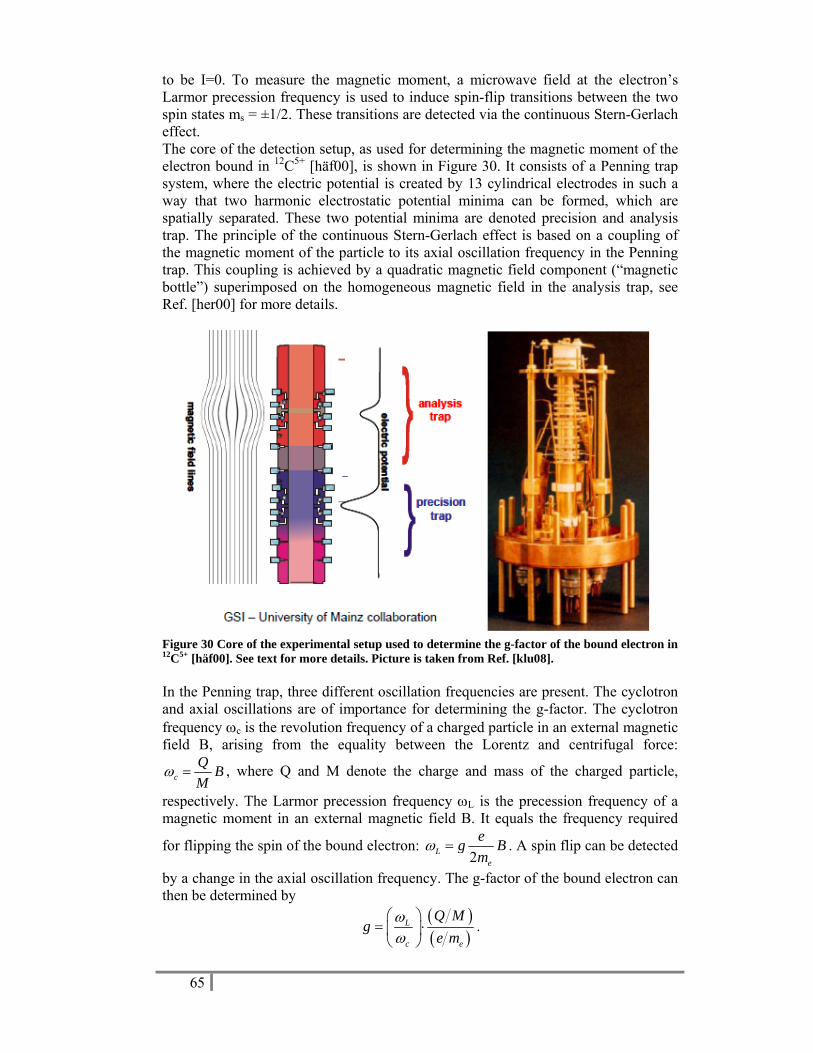
65
to be I=0. To measure the magnetic moment, a microwave field at the electron’s Larmor precession frequency is used to induce spin-flip transitions between the two spin states ms = ±1/2. These transitions are detected via the continuous Stern-Gerlach effect. The core of the detection setup, as used for determining the magnetic moment of the electron bound in 12C5+ [häf00], is shown in Figure 30. It consists of a Penning trap system, where the electric potential is created by 13 cylindrical electrodes in such a way that two harmonic electrostatic potential minima can be formed, which are spatially separated. These two potential minima are denoted precision and analysis trap. The principle of the continuous Stern-Gerlach effect is based on a coupling of the magnetic moment of the particle to its axial oscillation frequency in the Penning trap. This coupling is achieved by a quadratic magnetic field component (“magnetic bottle”) superimposed on the homogeneous magnetic field in the analysis trap, see Ref. [her00] for more details.
Figure 30 Core of the experimental setup used to determine the g-factor of the bound electron in 12C5+ [häf00]. See text for more details. Picture is taken from Ref. [klu08]. In the Penning trap, three different oscillation frequencies are present. The cyclotron and axial oscillations are of importance for determining the g-factor. The cyclotron frequency ωc is the revolution frequency of a charged particle in an external magnetic field B, arising from the equality between the Lorentz and centrifugal force:
ω =cQ BM
, where Q and M denote the charge and mass of the charged particle,
respectively. The Larmor precession frequency ωL is the precession frequency of a magnetic moment in an external magnetic field B. It equals the frequency required
for flipping the spin of the bound electron: 2
ω =Le
eg Bm
. A spin flip can be detected
by a change in the axial oscillation frequency. The g-factor of the bound electron can then be determined by
( )( )
ωω
⎛ ⎞= ⋅⎜ ⎟⎝ ⎠
L
c e
Q Mg
e m.
66
The measurements are performed with one ion only in order to enhance the precision. When, e.g., 100 ions are present in the trap, the resolving power of the cyclotron resonance signal is only 104. With only one ion in the trap, however, Coulomb interactions are avoided and a resolving power is achieved of 109. The Penning traps are cooled to liquid-helium temperature for eliminating relativistic mass shifts. Furthermore, the cooling features small oscillation amplitudes (<50 μm) minimizing systematic errors due to inhomogeneities of the magnetic field or anharmonicities of the electrostatic trapping field. The spin direction of the bound electron is detected via the axial oscillation frequency in the inhomogeneous field of the analysis trap. Then the ion is transferred to the precision trap by adiabatically moving the electric potential minimum. In the precision trap, the inhomogeneity of the magnetic field is 1000 times smaller, where, thus, spin flips can be induced by a microwave field with a higher precision as would be the case in the analysis trap. Finally, the ion is transported back to the analysis trap to detect if a spin flip occurred in the precision trap or not. It was found that the ion was never lost in the transfer from analysis to precision trap and vice versa. The influence of temporal fluctuations of the magnetic field is strongly reduced by measuring the cyclotron frequency in the precision trap, while simultaneously applying the microwave field to induce spin-flip transitions. This technique has been applied to measure the g-factor of 12C5+ [häf00,her00] and 16O7+ [ver03] to a precision of ~10-9, which is as precise as the theoretical value. It was found that the theoretical and experimental values are in good agreement. However, because the QED correction terms scale as Z2, QED tests in stronger fields are of particular interest. Furthermore, if QED calculations can be safely treated up to a precision of 10-9, then measuring the magnetic moment of the bound electron with a precision of 10-9, allows the determination of the nuclear spin magnetic moment up to a precision of 10-6. If, moreover, differences of magnetic moments ΔgA,A’ are measured between two isotopes having respective mass numbers A and A’, the δ<r2> values can be determined with exact calculations [gla02]. It is important to note that such studies will require the installation of an Electron Beam Ion Trap (EBIT) device, which is able to ionize the desired element to a charge state of (Z-1)+.
6.5.3 Further unique opportunities at ISOL@MYRRHA Apart from the cases discussed above, there are a number of other unique opportunities requiring ample development work and beam time for testing. Below, examples are briefly listed to illustrate the possibilities [klu09]:
• If the nuclear g-factor of the bare nucleus can be measured in a similar way as described in paragraph 6.5.2.3 and is compared to that measured for the neutral atom, then, for the first time, the calculations of the corrections for diamagnetism could be checked.
• The measurement of the hyperfine splitting (i.e. the A-factor) in hydrogen-like heavy ions by laser spectroscopy would enable a high-accuracy determination of the hyperfine anomaly.
• Using the measured magnetic moment of the bare nucleus and the measured A-factor of the hydrogen-like ion would, for the first time, allow to determine the Bohr-Weisskopf correction epsilon (see section 6.5.1.1).
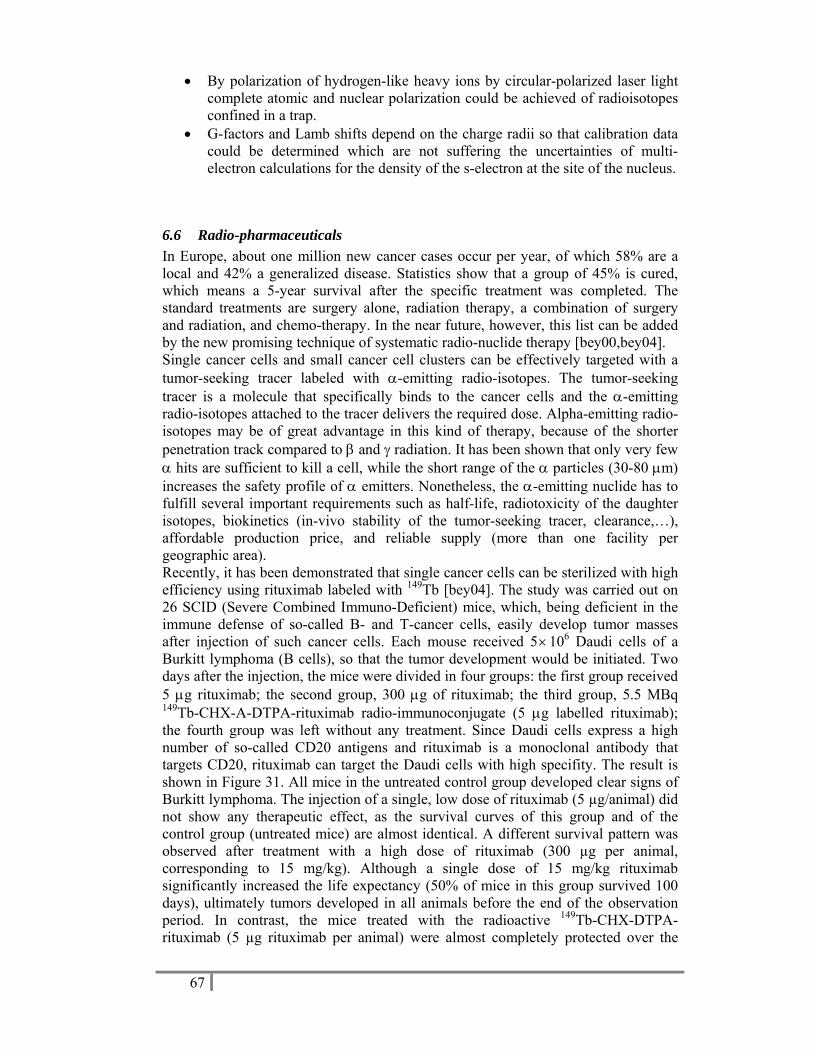
67
• By polarization of hydrogen-like heavy ions by circular-polarized laser light complete atomic and nuclear polarization could be achieved of radioisotopes confined in a trap.
• G-factors and Lamb shifts depend on the charge radii so that calibration data could be determined which are not suffering the uncertainties of multi-electron calculations for the density of the s-electron at the site of the nucleus.
6.6 23B25BRadio-pharmaceuticals In Europe, about one million new cancer cases occur per year, of which 58% are a local and 42% a generalized disease. Statistics show that a group of 45% is cured, which means a 5-year survival after the specific treatment was completed. The standard treatments are surgery alone, radiation therapy, a combination of surgery and radiation, and chemo-therapy. In the near future, however, this list can be added by the new promising technique of systematic radio-nuclide therapy [bey00,bey04]. Single cancer cells and small cancer cell clusters can be effectively targeted with a tumor-seeking tracer labeled with α-emitting radio-isotopes. The tumor-seeking tracer is a molecule that specifically binds to the cancer cells and the α-emitting radio-isotopes attached to the tracer delivers the required dose. Alpha-emitting radio-isotopes may be of great advantage in this kind of therapy, because of the shorter penetration track compared to β and γ radiation. It has been shown that only very few α hits are sufficient to kill a cell, while the short range of the α particles (30-80 μm) increases the safety profile of α emitters. Nonetheless, the α-emitting nuclide has to fulfill several important requirements such as half-life, radiotoxicity of the daughter isotopes, biokinetics (in-vivo stability of the tumor-seeking tracer, clearance,…), affordable production price, and reliable supply (more than one facility per geographic area). Recently, it has been demonstrated that single cancer cells can be sterilized with high efficiency using rituximab labeled with 149Tb [bey04]. The study was carried out on 26 SCID (Severe Combined Immuno-Deficient) mice, which, being deficient in the immune defense of so-called B- and T-cancer cells, easily develop tumor masses after injection of such cancer cells. Each mouse received 5×10⁶ Daudi cells of a Burkitt lymphoma (B cells), so that the tumor development would be initiated. Two days after the injection, the mice were divided in four groups: the first group received 5 μg rituximab; the second group, 300 μg of rituximab; the third group, 5.5 MBq 149Tb-CHX-A-DTPA-rituximab radio-immunoconjugate (5 μg labelled rituximab); the fourth group was left without any treatment. Since Daudi cells express a high number of so-called CD20 antigens and rituximab is a monoclonal antibody that targets CD20, rituximab can target the Daudi cells with high specifity. The result is shown in Figure 31. All mice in the untreated control group developed clear signs of Burkitt lymphoma. The injection of a single, low dose of rituximab (5 µg/animal) did not show any therapeutic effect, as the survival curves of this group and of the control group (untreated mice) are almost identical. A different survival pattern was observed after treatment with a high dose of rituximab (300 µg per animal, corresponding to 15 mg/kg). Although a single dose of 15 mg/kg rituximab significantly increased the life expectancy (50% of mice in this group survived 100 days), ultimately tumors developed in all animals before the end of the observation period. In contrast, the mice treated with the radioactive 149Tb-CHX-DTPA-rituximab (5 µg rituximab per animal) were almost completely protected over the
68
entire observation period, with only one mouse in this group being lost after 48 days due to abdominal tumor growth. The remaining eight mice (89%) showed normal behavior without any signs of disease for 4 months after injection with Daudi cells. All of these mice were sacrificed after 120 days and were found to be tumor-free at dissection. Thus, a single injection of 5.5 MBq 149Tb-labelled rituximab results in long-term survival without evidence of any disease at 120 days. Furthermore, it was concluded that injection of a potentially therapeutic activity of 5 GBq 149Tb- rituximab, in a 70-kg patient, would deliver a bone marrow radiation dose far below the critical level.
Figure 31 Survival graph of SCID mice after injection of 5× 10⁶ Daudi cells and followed by four different treatments [bey04]. In conclusion, the work of Ref. [bey04] illustrates the potential of radio-pharmaceuticals like 149Tb. Although the technology for producing those radio-pharmaceuticals already exists, the number of facilities producing them is limited. The high-intensity beam and long available beam times at ISOL@MYRRHA provide a unique opportunity for systematic production of radio-pharmaceuticals on a large scale. The estimated production yield of 149Tb on a Ta target, for example, is 2×10¹⁰ ions/s, which means that 1.5 hours of beam time are required for the production of one 5-GBq sample. This would correspond to a supply of almost six thousand patient doses per year. With the upgrade to a 1-GeV proton beam, the production cross section of 149Tb (and correspondingly the number of patient doses) would further increase with a factor of two to three.
69
7 Timeline The MYRRHA accelerator driven system is planned to be deployed in 2020. Presently, the conceptual design of MYRRHA/XT-ADS as it is being realised in the European FP6 programme EUROTRANS is nearing its completion.
In the next period (2009-2013), the project team will work in parallel on three different major tasks. The first is the advanced engineering design of the machine (2009 – 2011). This effort is framed in the European FP7 programme CDT (central design team). In the subsequent years 2012-2013 it is planned to draft the technical specifications of the different components, to publish the call for tenders and to award the manufacturing contracts. The second parallel task (2009-2011) is to perform the tests of innovative components. Thirdly, the project team will spend a significant amount of time on the licensing and permit process. Eventually, the goal of the efforts is to obtain the authorization for construction at the end of 2013.
With a construction permit, the construction/manufacturing of the different components and the civil engineering works at the Mol site are scheduled for 2014-2016. In 2017 the different components will be assembled together leaving the period 2018-2019 for tests and commissioning at progressive levels of power. After this, MYRRHA should be ready for full power operation in 2020.
It is clear that the realisation schedule for ISOL@MYRRHA will be closely related to that of the MYRRHA ADS. Following a backward timing strategy, ISOL@MYRRHA should be able to take its first beam during the commissioning phase of the accelerator starting in 2018. In order or reach this goal, the engineering design of the ISOL system and the target stations must be completed by 2013 meaning that the concept design should be finished by 2011. With this timing, construction contracts may be awarded in 2014. It is important to note that this event coincides with the key date of the construction authorisation of MYRRHA. Manufacturing of components and construction of the ISOL@MYRRHA related buildings will then take place in the period 2015-2016. As with the ADS system, 2017 will be dedicated to the assembly and installation of the ISOL and target system.

70
8 References [ali06] I.P. Aliseda, Ph.D. thesis “New developments on preparation of cooled
and bunched radioactive ion beams at ISOL-facilities: the ISCOOL project and the rotating wall cooling”, Universitat Politècnica de Catalunya, 2006
[alk04] J. Al-Khalili: “An introduction to halo nuclei”. In: The Euroschool Lectures on Physics with Exotic Beams, Vol. I, ed. by J. Al-Khalili, E. Roeckl, Lect. Notes Phys. 651 (Springer, Berlin Heidelberg, 2004), p. 77
[aoi02] N. Aoi et al., Phys. Rev. C 66 (2002) 014301
[aud97] G. Audi, O. Bersillon, J. Blachot, and A. H. Wapstra, Nucl. Phys. A 624 (1997) 1
[äys03] J. Äystö and A. Jokinen, J. Phys. B 36 (2003) 573
[bec03] M. Beck al., Nucl. Instr. and Meth. A503 (2003) 567.
[bey00] G. J. Beyer, Hyp. Int. 129 (2000) 529
[bey04] G. J. Beyer et al., Eur. J. Nucl. Med. Mol. Imaging 31 (2004) 547
[bla03] K. Blaum et al., Nucl. Instr. Meth. B 204 (2003) 331
[bla08] B. Blank, presentation BriX workshop 2008, SCK-CEN, Mol, Belgium, 2008.
[bla09] URL PENTATRAP project: http://www.mpi-hd.mpg.de/blaum/high-precision-ms/pentatrap.en.html#motivation
[bri03] P. Bricault, M. Dombsky, A. Dowling, M. Lane, Nucl. Instr. and Meth. B 204 (2003) 319.
[bri07] P. G. Bricault, M. Dombsky, J. Lassen, F. Ames, Proceeding of the 18th International Conference on Cyclotrons and their Applications, Giardini Naxos, Italy, 2007.
[büs08] J. Büscher et al., Nucl. Instr. Meth. B 266 (2008) 4652
[cha08] S. Chabod et al., EURISOL-DS: “Optimization of in-target yields for RIB production: Part I: direct targets” (2008)
[cho03] K.H. Chow et al., Physica B 340-342 (2003) 1151
[coc09] T. Cocolios, ISOLDE experiment IS456
[dav08] C.N. Davids and D. Peterson, Nucl. . Instr. and Meth. B 266 (2008) 4449
[dec09] S. Decoster, S. Cottenier, B. De Vries, H. Emmerich, U. Wahl, J. G. Correia, and A. Vantomme, Phys. Rev. Lett. 102 (2009) 065502
[des80] R.D. Deslattes, E.G. Kessler, W. C. Sauder, and A. Henins, Ann. Phys. 129 (1980) 378.
[des03] P. Descouvemont, C. Daniel, and D. Baye, Phys. Rev. C 67 (2003) 044309.
[dom03] M. Dombsky, P. Bricault, P. Schmor, M. Lane, Nucl. Instr. and Meth. B 204 (2003) 191.

71
[dom04] M. Dombsky, P. Bricault, V. Hanemaayer, Nucl. Phys. A 746 (2004) 32c.
[dom07] M. Dombsky et al., Nucl. Instr. and Meth. B 264 (2007) 117.
[dom08] M. Dombsky, presentation BriX workshop 2008, SCK-CEN, Mol, Belgium, 2008.
[ewa04] G. Ewald et al., Phys. Rev. Lett. 93 (2004) 113002
[fit04] M.R. Fitzsimmons et al. J. Magn. Magn. Mater. 271 (2004) 103
[fla09] K. Flanagan et al., ISOLDE experiment IS471
[frå08] H. Frånberg et al., Nucl. Instr. and Meth. B 266 (2008) 4502
[fyn00] H.O.U. Fynbo et al., Nucl. Phys. A 677 (2000) 38.
[gam04] UUhttp://rencurel.essworkshop.org/documents/YellowBookCDrom/data/ 11_4_4.pdf UU
[gla02] D. A. Glazov and V. M. Shabaev, Phys. Lett. A 297 (2002) 408
[gov95] J. Govaerts et al., J. Phys. G 21 (1995) 1675.
[gus00] M. G. H. Gustavsson and A.-M. Martensson-Pendrill, Hyp. Int. 127 (2000) 347
[häf00] H. Häffner et al., Phys. Rev. Lett. 85 (2000) 5308
[har09] J.C. Hardy and I.S. Towner, Phys. Rev. C 79 (2009) 055502
[her00] N. Hermanspahn et al., Phys. Rev. Lett. 84 (2000) 427
[hof91] H. Hofsäss and G. Lindner, Phys. Rep. 201 (1991) 121
[hub03] R. Huber et al., Phys. Rev. Lett 90 (2003) 202301.
[iso09] http://isolde.web.cern.ch/isolde/UU.
[jac67] J.D. Jackson, S.B. Treiman, H.W. Wyld, Nucl. Phys. A 4 (1967) 206.
[jep02] H. Jeppesen et al., Nucl. Phys. A 709 (2002) 119
[jol99] J. Jolie, “Gamma Ray Spectroscopy with Ultra-High Precision” Europhysics News March/April 1999, p. 52
[jon01] B. Jonson and K. Riisager, Nucl. Phys. A 693 (2001) 77. [kös08] U. Köster, presentation BriX workshop 2008, SCK-CEN, Mol, Belgium,
2008.
[kee08] T.A. Keeler et al., Phys. Rev. B 77 (2008) 144429
[kes01] E. G. Kessler Jr. et al., Nucl. Instr. Meth. A 457 (2001) 187
[klu08] H.-J. Kluge, presentation BriX workshop 2008, SCK-CEN, Mol, Belgium, 2008.
[klu09] H.-J. Kluge, private communication
[let08] J. Lettry, presentation BriX workshop 2008, SCK-CEN, Mol, Belgium, 2008.
[luk06] S. Lukic et al., Nucl. Instr. and Meth. A 565 (2006) 784.
[lun09] D. Lunney, EURISOL-DS: “Advanced development of a high-current ion cooler/buncher” (2009)
72
[mat06] T. Materna et al., Nucl. Instr. Meth. A 569 (2006) 890
[mat09] C.M. Mattoon et al., Phys. Rev. C 80 (2009) 034318
[mel07] D. Melconian et al. Phys. Lett. B649 (2007) 370.
[mie07] K. Miernik et al., Phys. Rev. C 76 (2007) 041304(R).
[moo05] I. D. Moore et al., J. Phys. G 31 (2005) S1499
[mor01] E. Morenzoni et al. Hyperf. Int. 133 (2001) 179
[mor04a] D. J. Morrissey and B. M. Sherill: ‘In-Flight Separation of Projectile Fragments’. In: The Euroschool Lectures on Physics with Exotic Beams, Vol. I, ed. by J. Al-Khalili, E. Roeckl, Lect. Notes Phys. 651 (Springer, Berlin Heidelberg, 2004), p. 113
[mor04b] G.D. Morris et al., Phys. Rev. Lett. 93 (2004) 157601
[mue07] P. Mueller et al., Phys. Rev. Lett. 99 (2007) 252501
[nav91] O. Naviliat-Cuncic, T.A. Girard, J. Deutsch and N. Severijns, J. Phys. G 17 (1991) 919.
[nav00] P. Navrátil et al., Phys Rev. C 62 (2000) 054311
[nav09a] O. Naviliat-Cuncic and N. Severijns, Phys. Rev. Lett. 102 (2009) 142302.
[nav09b] O. Naviliat-Cuncic and N. Severijns, Eur. Phys. J. A, in print (2009).
[nie01] E. Nielsen, D.V. Fedorov, A.S. Jensen, and E. Garrido, Phys. Rev. Lett. 88 (2002) 094801
[nie02] A. Nieminen et al., Phys. Rev. Lett. 88 (2002) 094801
[neu02] R. Neugart, Eur. Phys. J. A 15 (2002) 35
[nör09] W. Nörtershäuser et al., Phys. Rev. Lett. 102 (2009) 062503
[nsa07] UUhttp://www.science.doe.gov/np/nsac/nsac.html UU
[nup04] http://www.nupecc.org/pub/lrp03/long_range_plan_2004.pdf
[oec08] http://www.oecd.org/dataoecd/35/41/40638321.pdf
[oko03] J. Okołowicz, M. Płoszajczak, and I. Rotter, Phys. Rep. 374 (2003) 271 [oka08] K. Okada et al., Phys. Rev. Lett. 101 (2008) 212502
[opl09] http://indico.cern.ch/conferenceDisplay.py?confId=51128
[par07] T.J. Parolin et al., Phys. Rev. Lett. 98 (2007) 047601
[per97] H. Persson et al., Phys. Rev. A 56 (1997) 2499(R)
[per98] J. R. Persson, Eur. Phys. J. A 2 (1998) 3
[per06] UUhttp://www.hkr.se/templates/Page____3951.aspxUU
[pie01] S. C. Pieper et al., Phys. Rev. C 64 (2001) 014001
[pie02] S.C. Pieper, K. Varga, and R.B. Wiringa, Phys. Rev. C 66 (2002) 044310.
[raa08] R. Raabe et al., Phys. Rev. Lett. 101 (2008) 212501.
[reg08] Regeerakkoord Leterme I (UUhttp://www.yvesleterme.be/nl/beleid/ regeerakkoordUU).

73
[sal07a] Z. Salman et al., Phys. Rev. B 75 (2007) 073405
[sal07b] Z. Salman et al., Phys. Rev. Lett. 98 (2007) 167001
[sán06] R. Sánchez et al., Phys. Rev. Lett. 96 (2006) 033002
[sar04] F. Sarazin et al., Phys. Rev. C 70, 031302 (2004).
[sci04] See, e.g., N. Scielzo et al., Phys. Rev. Lett. 93 (2004) 102501 ; A. Gorelov et al., Phys. Rev. Lett 94 (2005) 142501; R.Rodriguez, et al., Nucl. Instr. and Meth. A565 (2006) 876; G.P. Berg et al., Nucl. Instr. and Meth. B204 (2003) 52.
[sev93] N. Severijns et al., Phys. Rev. Lett. 70 (1993) 4047 and 73 (1993) 611 (err.).
[sev98] N. Severijns et al., Nucl. Phys. A629 (1998) 423c.
[sev06] N. Severijns, M. Beck and O. Naviliat-Cuncic, Rev. Mod. Phys. 78 (2006) 991.
[sev08a] N. Severijns, presentation BriX workshop 2008, SCK-CEN, Mol, Belgium, 2008.
[sev08b] N. Severijns, M. Tandecki, T. Phalet and I.S. Towner, Phys. Rev. C 78 (2008) 055501.
[sil99] R. Silberberg, C.H. Tsao, Phys. Reports 191 (1999) 351.
[smi05] D. Smirnov et al., Nucl. Instr. Meth. A 547 (2005) 480
[son09] T. Sonoda et al., Nucl. Instr. Meth. B (in print); UUarXiv:0904.3176v2UU
[spr97] G.D. Sprouse and L.A. Orozco, Annu. Rev. Nucl. Part. Sci. 47 (1997) 429
[sra06] G. Srajer et al., J. Magn. Magn. Mater. 307 (2006) 1
[sto06] T. Stora et al., EURISOL-DS: “The EURISOL facility: Feasibility study for the 100 kW direct targets” (2006)
[tan06] M. Tandecki, Ms. Thesis, Kath. Universiteit Leuven (2006), unpublished and M. Tandecki et al., to be published.
[tes95] Handbook of modern ion beam materials analysis, edited by J. R. Tesmer and M. Nastasi (Materials Research Society, Pittsburg, 1995)
[tim96] N. K. Timofeyuk and P. Descouvemont, J. Phys. G 22 (1996) L99
[tom98] M. Tomaselli et al., Phys. Rev. C 58 (1998) 1524
[tri09] UUhttp://www.triumf.info/facility/research_fac/yield.phpUU.
[tur06] E. M. Tursunov, D. Baye, and P. Descouvemont, Phys. Rev. C 73 (2006) 014303
[vdu06] P. Van Duppen: ‘Isotope Separation On Line and Post Acceleration’. In: The Euroschool Lectures on Physics with Exotic Beams, Vol. II, ed. by J. Al-Khalili, E. Roeckl, Lect. Notes Phys. 700 (Springer, Berlin Heidelberg, 2006), p. 37
[ver03] J. Verdú et al., Hyp. Int. 146/147 (2003) 47
[wah04] U. Wahl et al., Nucl. Instr. and Meth. A 524 (2004) 245

74
[wan04] L.-B. Wang et al., Phys. Rev. Lett. 93 (2004) 142501
[wau09a] F. Wauters et al., arXiv [nucl-ex]0907.4594.
[wau09b] F. Wauters et al., arXiv [nucl-ex]0901.0081v2.
[wil07] R. Wilfinger, J. Lettry, and the EURISOL Task 3 Workgroup, Eur. Phys. J. Special Topics 150 (2007) 379.
[wil08] H. Wilschut, presentation BriX workshop 2008, SCK-CEN, Mol, Belgium, 2008.
[xu08] M. Xu et al., Journal of Magnetic Resonance 191 (2008) 47


![MYRRHA, Technology Development for the … · Web viewOne of the flagships of the nuclear infrastructure of SCK•CEN is the BR2 reactor [1], a flexible irradiation facility known](https://img.pdfslide.us/doc/110x75/5e5ad440101b4618b16aa655/myrrha-technology-development-for-the-web-view-one-of-the-flagships-of-the-nuclear.jpg)


![BEAM DYNAMICS AND DIAGNOSTICS FOR THE HIGH ENERGY … · ENERGY BEAM TRANSPORT LINE OF MINERVA PROJECT AT SCK-CEN References: [1] D.Vandeplassche, “The MYRRHA linear accelerator”,](https://img.pdfslide.us/doc/110x75/5fcbee61137253359e69b09b/beam-dynamics-and-diagnostics-for-the-high-energy-energy-beam-transport-line-of.jpg)