Embed Size (px)
Citation preview
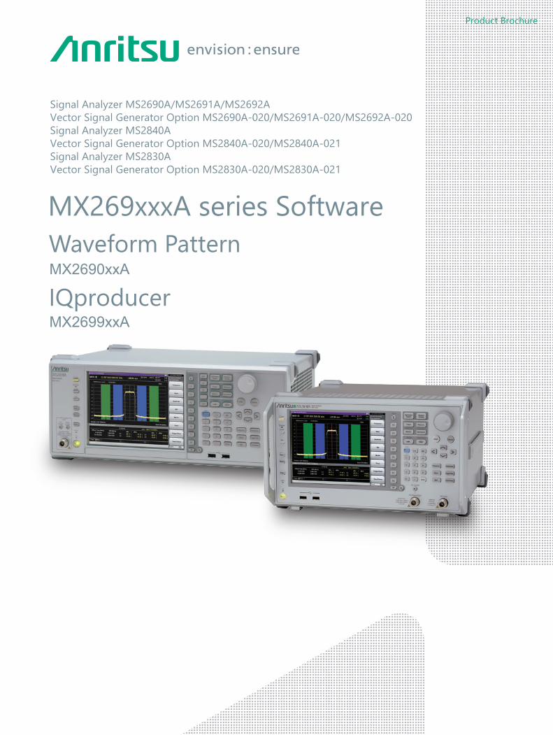
Product Brochure
Waveform PatternMX2690xxA
IQproducerMX2699xxA
MX269xxxA series Software
Signal Analyzer MS2690A/MS2691A/MS2692AVector Signal Generator Option MS2690A-020/MS2691A-020/MS2692A-020Signal Analyzer MS2840AVector Signal Generator Option MS2840A-020/MS2840A-021Signal Analyzer MS2830AVector Signal Generator Option MS2830A-020/MS2830A-021
MX269xxxA series Software
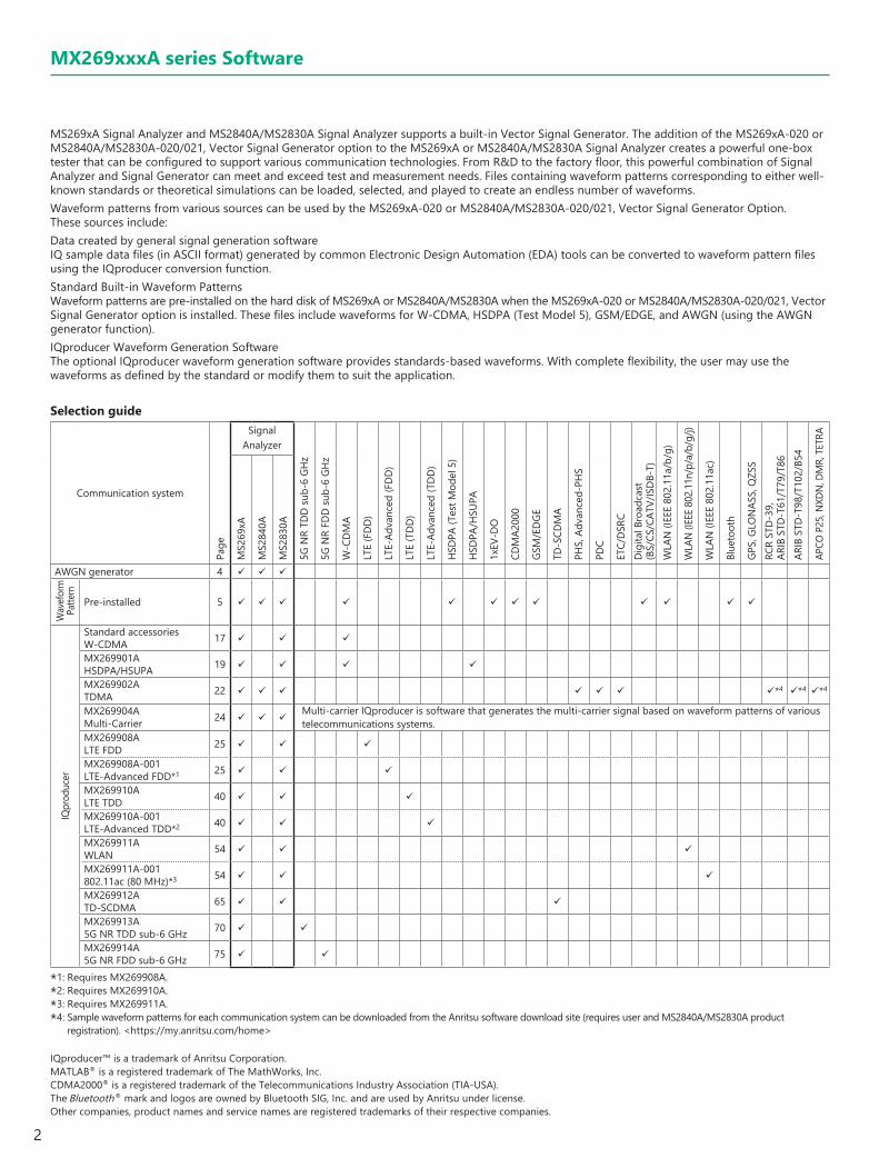
MS269xA Signal Analyzer and MS2840A/MS2830A Signal Analyzer supports a built-in Vector Signal Generator. The addition of the MS269xA-020 or MS2840A/MS2830A-020/021, Vector Signal Generator option to the MS269xA or MS2840A/MS2830A Signal Analyzer creates a powerful one-box tester that can be configured to support various communication technologies. From R&D to the factory floor, this powerful combination of Signal Analyzer and Signal Generator can meet and exceed test and measurement needs. Files containing waveform patterns corresponding to either well-known standards or theoretical simulations can be loaded, selected, and played to create an endless number of waveforms.Waveform patterns from various sources can be used by the MS269xA-020 or MS2840A/MS2830A-020/021, Vector Signal Generator Option.These sources include:Data created by general signal generation softwareIQ sample data files (in ASCII format) generated by common Electronic Design Automation (EDA) tools can be converted to waveform pattern files using the IQproducer conversion function.Standard Built-in Waveform PatternsWaveform patterns are pre-installed on the hard disk of MS269xA or MS2840A/MS2830A when the MS269xA-020 or MS2840A/MS2830A-020/021, Vector Signal Generator option is installed. These files include waveforms for W-CDMA, HSDPA (Test Model 5), GSM/EDGE, and AWGN (using the AWGN generator function).IQproducer Waveform Generation SoftwareThe optional IQproducer waveform generation software provides standards-based waveforms. With complete flexibility, the user may use the waveforms as defined by the standard or modify them to suit the application.
Selection guide
Communication system
Page
rezylanAlangiS
5G N
R TD
D su
b-6
GHz
5G N
R FD
D su
b-6
GHz
W-C
DM
A
LTE
(FD
D)
LTE-
Adva
nced
(FD
D)
LTE
(TD
D)
LTE-
Adva
nced
(TD
D)
HSD
PA (T
est M
odel
5)
HSD
PA/H
SUPA
1xEV
-DO
CDM
A200
0
GSM
/ED
GE
TD-S
CDM
A
PHS,
Adv
ance
d-PH
S
PDC
ETC/
DSR
CD
igita
l Bro
adca
st(B
S/CS
/CAT
V/IS
DB-
T)W
LAN
(IEE
E 80
2.11
a/b/
g)
WLA
N (I
EEE
802.
11n/
p/a/
b/g/
j)
WLA
N (I
EEE
802.
11ac
)
Blue
toot
h
GPS,
GLO
NAS
S, Q
ZSS
RCR
STD
-39,
AR
IB S
TD-T
61/T
79/T
86AR
IB S
TD-T
98/T
102/
B54
APCO
P25
, NXD
N, D
MR,
TET
RA
MS2
69xA
MS2
840A
MS2
830A
AWGN generator 4
Wav
efor
m
Patte
rn
Pre-installed 5
IQpr
oduc
er
Standard accessories W-CDMA 17
MX269901A HSDPA/HSUPA 19
MX269902A TDMA 22 *4 *4 *4
MX269904A Multi-Carrier 24
Multi-carrier IQproducer is software that generates the multi-carrier signal based on waveform patterns of various telecommunications systems.
MX269908A LTE FDD 25
MX269908A-001 LTE-Advanced FDD*1 25
MX269910A LTE TDD 40
MX269910A-001 LTE-Advanced TDD*2 40
MX269911A WLAN 54
MX269911A-001 802.11ac (80 MHz)*3 54
MX269912A TD-SCDMA 65
MX269913A 5G NR TDD sub-6 GHz 70
MX269914A 5G NR FDD sub-6 GHz 75
*1: Requires MX269908A.*2: Requires MX269910A.*3: Requires MX269911A.*4: Sample waveform patterns for each communication system can be downloaded from the Anritsu software download site (requires user and MS2840A/MS2830A product
registration). <https://my.anritsu.com/home>
IQproducer™ is a trademark of Anritsu Corporation.MATLAB® is a registered trademark of The MathWorks, Inc.CDMA2000® is a registered trademark of the Telecommunications Industry Association (TIA-USA).The Bluetooth® mark and logos are owned by Bluetooth SIG, Inc. and are used by Anritsu under license.Other companies, product names and service names are registered trademarks of their respective companies.
2

HDD
From IQproducer
W-CDMA
Memory
Signal Analyzer MS269xASignal Analyzer MS2840A/MS2830A
ARB memory 1 GB = 256 Msamples*1
(Vector Signal Generator MS269xA-020)
GSM/EDGE
WLAN
CDMA2000
CDMA2000 1xEV-DO
Digital Broadcast
1xEV-DO Reverse Receiver Test
Output signal
AWGN Generator*2
(MS269xA-020Pre-installed function)
HSDPA/HSUPA IQproducer MX269901A etc.
Optional waveform patterns are saved in the MS269xA/MS2840A/MS2830A once and then loaded to waveform memory for use.
IQproducer is PC application software used for generating waveform pattern files for the Vector Signal Generator Option by editing parameters for the modulation signals matching the target communication system.The generated waveform pattern files are saved in the MS269xA or MS2840A/MS2830A once and then loaded to the waveform memory for use.
Download
Waveform patterns saved on hard disk
IQproducer Operating Environment
OS Windows 2000 Professional*1, Windows XP*2, Windows Vista*3, Windows 7 Enterprise (32-bit)*2, Windows 7 Professional (32-bit/64-bit)*2, Windows 10*4
CPU Pentium III 1 GHz equivalent or faster
Memory 512 MB or more
Hard Disk Space5 GB or more free space on the drive where this software is to be installed.The free hard disk space necessary to create waveform pattern varies depending on the waveform pattern size. The free disk space of 27 GB or greater is required to create four maximum (512 Msamples) waveform patterns.
*1: Does not support IQproducer Version 13.00 and later*2: Supports IQproducer Version 12.00 and later*3: Supports IQproducer Version 12.00 to Version 16.01*4: Supports IQproducer Version 17.00 and later
Windows® is a registered trademark of Microsoft Corporation in the USA and other countries.Pentium® is registered trademarks of Intel Corporation or its subsidiaries in the USA and other countries.
MX269xxxA series Software
*1: The MS2840A/MS2830A-020/021 arbitrary waveform memory is 256 MB (64 Msamples). Expansion to 1 GB (256 Msamples) requires the separate MS2840A/MS2830A-027 ARB Memory Upgrade 256 MSa for Vector Signal Generator option.
*2: The MS2840A/MS2830A-020/021 requires the separate MS2840A/MS2830A-028 AWGN option.
3

MS269xA MS2840A MS2830A
Additive White Gaussian Noise (AWGN) GeneratorMS269xA-020: Pre-installed functionMS2840A/MS2830A-020/021: Requires the separate MS2840A/MS2830A-028 AWGN option
The noise signal of the AWGN generator can be added to the wanted signal of the arbitrary waveform memory.
Output signal
Memory
ARB memory 1 GB = 256 Msamples*1
AWGN Generator*2
(MS269xA-020 Pre-installed function)
Vector Signal Generator MS269xA-020
AWGN
C/N Ratio
Wanted Signal AmplitudeCarrier Power
Noise Power
Frequency
AWGN Bandwidth
Carrier Power: Output level of wanted signalNoise Power: Output level value of AWGN converted by bandwidth of
wanted signal (It is not displayed on the screen.)C/N Ratio: Level ratio of Carrier Power and Noise Power.Amplitude: Combination of wanted signal level and AWGN level.
AWGN BandwidthThe bandwidth of AWGN is the same as the sampling clock of the wanted signal.Sample:When the condition of the wanted signal is the following
• W-CDMA• BW = 3.84 MHz• Over Sampling Rate = 4
Calculation:AWGN Bandwidth= 3.84 MHz × 4 = 15.36 MHz
Parameter Setting Range
Display Function
AWGN On/Off On, Off
C/N Set Signal
Carrier, Noise, ConstantCarrier: Noise Power is a fixed value.
Carrier Power is set.Noise: Carrier Power is a fixed value.
Noise Power is set.Constant: Amplitude is a fixed value.
Level ratio of C/N is set.
Carrier Power The output level of Carrier Power is set.
C/N RatioLevel ratio of Carrier Power and converted Noise Power is set.
–40 dB ≤ C/N Ratio ≤ +40 dB
AWGN Supports Dynamic Range TestingThe 3GPP specifications for testing receiver dynamic range require a AWGN + W-CDMA modulation signal.The Internal AWGN generator can be used to produce the AWGN signal.
Wanted Signal + AWGN Output Waveform
Condition of Parameter Setting RangeThe parameter of the AWGN generator has the following restriction.
• –40 dB ≤ C/N Ratio ≤ +40 dB• Amplitude ≤ 0 dBm
*1: The MS2840A/MS2830A-020/021 arbitrary waveform memory is 256 MB (64 Msamples). Expansion to 1 GB (256 Msamples) requires the separate Vector Signal Generator ARB Memory Upgrade 256 MSa MS2840A/MS2830A-027.
*2: The MS2840A/MS2830A-020/021 requires the separate AWGN MS2840A/MS2830A-028.
4

MS269xA MS2840A MS2830AStandard
W-CDMA Waveform Patterns
For Evaluating Base Station Transmitter Devices (TS 25.141 Test Model 1 to 6)
TestModel_1_4DPCHTestModel_1_8DPCHTestModel_1_16DPCHTestModel_1_32DPCHTestModel_1_64DPCHTestModel_1_64×2_10MTestModel_1_64×2_15MTestModel_1_64DPCH×2TestModel_1_64DPCH×3TestModel_1_64DPCH×4TestModel_2TestModel_3_4DPCHTestModel_3_8DPCHTestModel_3_16DPCHTestModel_3_32DPCHTestModel_4TestModel_4_CPICHTestModel_5_2HSPDSCHTestModel_5_4HSPDSCHTestModel_5_8HSPDSCHTestModel_6_4HSPDSCHTestModel_6_8HSPDSCH
For Testing BS Receiver Performance (TS 25.101/ 25.104 UL RMC 12.2 to 384 kbps)
UL_RMC_12_2kbpsUL_RMC_64kbpsUL_RMC_144kbpsUL_RMC_384kbpsUL_AMR_TFCS1UL_AMR_TFCS2UL_AMR_TFCS3UL_ISDNUL_64kbps_PacketUL_Interfere
For Evaluating UE Transmitter Devices (TS 25.101 A2.1)
UL_RMC_12_2kbps_TX
Uplink and downlink W-CDMA modulation signals conforming to the 3GPP (FDD) standards can be output simply by selecting the waveform from the patterns on the internal hard disk without setting any complex 3GPP-compliant parameters.
For Testing UE Receiver Performance (TS 25.101 DL RMC 12.2 to 384 kbps)
DL_RMC_12_2kbps_RXDL_RMC_12_2kbpsDL_RMC_12_2kbps_MILDL_RMC_64kbpsDL_RMC_144kbpsDL_RMC_384kbpsDL_AMR_TFCS1DL_AMR_TFCS2DL_AMR_TFCS3DL_ISDNDL_384kbps_PacketDL_Interfere
The following W-CDMA waveform patterns are installed on the internal hard disk when MS269xA-020 or MS2840A/MS2830A-020/021, Vector Signal Generator Option is installed. Details for each pattern file is given on the next page.
5

MS269xA MS2840A MS2830A
W-CDMA Waveform Patterns List
Waveform Patterns Uplink/Downlink Channel 3GPP Evaluation
UL_RMC_12_2kbps*1
Uplink
DPCCH, DPDCH TS 25.141 A.2
BS Rx Test
UL_RMC_64kbps*1 DPCCH, DPDCH TS 25.141 A.3UL_RMC_144kbps*1 DPCCH, DPDCH TS 25.141 A.4UL_RMC_384kbps*1 DPCCH, DPDCH TS 25.141 A.5UL_AMR_TFCS1*1 DPCCH, DPDCH
TS 25.944 4.1.2UL_AMR_TFCS2*1 DPCCH, DPDCHUL_AMR_TFCS3*1 DPCCH, DPDCHUL_ISDN*1, *2 DPCCH, DPDCHUL_64kbps_Packet*1 DPCCH, DPDCHUL_Interfere DPCCH, DPDCH TS 25.141 IUL_RMC_12_2kbps_TX*1 DPCCH, DPDCH TS 25.101 A.2.1 UE Tx Device TestDL_RMC_12_2kbps_RX*1
Downlink
P-CPICH, SCH, PICH, DPCH TS 25.101 A.3.1TS 25.101 C.3.1
UE Rx Test
DL_RMC_12_2kbps_MIL*1 P-CPICH, SCH, PICH, DPCH, OCNSDL_RMC_12_2kbps*1 P-CPICH, SCH, PICH, DPCH, OCNS TS 25.101 A.3.1
TS 25.101 C.3.2DL_RMC_64kbps*1 P-CPICH, SCH, PICH, DPCH, OCNSDL_RMC_144kbps*1 P-CPICH, SCH, PICH, DPCH, OCNS TS 25.101 A.3.3/C3.2DL_RMC_384kbps*1 P-CPICH, SCH, PICH, DPCH, OCNS TS 25.101 A.3.4/C3.2DL_AMR_TFCS1*1 P-CPICH, SCH, PICH, DPCH, OCNS
TS 25.944 4.1.1.3TS 25.101 C.3.2
DL_AMR_TFCS2*1 P-CPICH, SCH, PICH, DPCH, OCNSDL_AMR_TFCS3*1 P-CPICH, SCH, PICH, DPCH, OCNSDL_ISDN*1 P-CPICH, SCH, PICH, DPCH, OCNSDL_384kbps_Packet*1 P-CPICH, SCH, PICH, DPCH, OCNSDL_Interfere P-CPICH, P-CCPCH, SCH, PICH, OCNS TS 25.101 C.4DL_CPICH P-CPICH —TestModel_1_4DPCH P-CPICH, P-CCPCH, SCH, PICH, S-CCPCH, 4DPCH
TS 25.141 6.1.1 BS Tx Device Test
TestModel_1_8DPCH P-CPICH, P-CCPCH, SCH, PICH, S-CCPCH, 8DPCHTestModel_1_16DPCH P-CPICH, P-CCPCH, SCH, PICH, S-CCPCH, 16DPCHTestModel_1_32DPCH P-CPICH, P-CCPCH, SCH, PICH, S-CCPCH, 32DPCHTestModel_1_64DPCH P-CPICH, P-CCPCH, SCH, PICH, S-CCPCH, 64DPCHTestModel_1_64DPCH×2*2 P-CPICH, P-CCPCH, SCH, PICH, S-CCPCH, 64DPCHTestModel_1_64DPCH×3*2 P-CPICH, P-CCPCH, SCH, PICH, S-CCPCH, 64DPCHTestModel_1_64DPCH×4*2 P-CPICH, P-CCPCH, SCH, PICH, S-CCPCH, 64DPCHTestModel_1_64×2_10M*2, *3 P-CPICH, P-CCPCH, SCH, PICH, S-CCPCH, 64DPCHTestModel_1_64×2_15M*2, *3 P-CPICH, P-CCPCH, SCH, PICH, S-CCPCH, 64DPCHTestModel_2 P-CPICH, P-CCPCH, SCH, PICH, S-CCPCH, 3DPCHTestModel_3_4DPCH P-CPICH, P-CCPCH, SCH, PICH, S-CCPCH, 4DPCHTestModel_3_8DPCH P-CPICH, P-CCPCH, SCH, PICH, S-CCPCH, 8DPCHTestModel_3_16DPCH P-CPICH, P-CCPCH, SCH, PICH, S-CCPCH, 16DPCHTestModel_3_32DPCH P-CPICH, P-CCPCH, SCH, PICH, S-CCPCH, 32DPCHTestModel_4 P-CCPCH, SCHTestModel_4_CPICH P-CPICH, P-CCPCH, SCH
TestModel_5_4DPCH P-CPICH, P-CCPCH, SCH, PICH, S-CCPCH, 4DPCH, HS-SCCH, 4HS-PDSCH
TestModel_5_2HSPDSCH P-CPICH, P-CCPCH, SCH, PICH, S-CCPCH, 6DPCH, HS-SCCH, 2HS-PDSCH
TestModel_5_4HSPDSCH P-CPICH, P-CCPCH, SCH, PICH, S-CCPCH, 14DPCH, HS-SCCH, 4HS-PDSCH
TestModel_5_8HSPDSCH P-CPICH, P-CCPCH, SCH, PICH, S-CCPCH, 30DPCH, HS-SCCH, 8HS-PDSCH
TestModel_6_4HSPDSCH P-CPICH, P-CCPCH, SCH, PICH, S-CCPCH, 4DPCH, HS-SCCH, 4HS-PDSCH
TestModel_6_8HSPDSCH P-CPICH, P-CCPCH, SCH, PICH, S-CCPCH, 30DPCH, HS-SCCH, 8HS-PDSCH
*1: For MS2840A/MS2830A: ARB Memory Upgrade 256 Msample option must be installed to use this waveform pattern.*2: ×2, ×3, and ×4 indicate multi-carrier 2, 3, and 4, respectively.*3: 10M and 15M indicate the multi-carrier inter frequency gap.
Standard
W-CDMA Waveform Patterns
6

MS269xA MS2840A MS2830A
Adjacent Channel Leakage Power Ratio (ACPR)The ACPR is an important function for testing device distortion and receiver interference.
Complementary Cumulative Distribution Function (CCDF)
W-CDMA ACPR (Test Model 1, 64 DPCH, 1 Carrier)Waveform Pattern [Test_Model_1_64DPCH]
W-CDMA ACPR (Test Model 1, 64 DPCH, 4 Carrier)Waveform Pattern [Test_Model_1_64DPCH × 4]
CCDF (Test Model 1, 64 DPCH, 1 Carrier)Waveform Pattern [Test_Model_1_64DPCH]
CCDF (Test Model 1, 64 DPCH, 4 Carrier)Waveform Pattern [Test_Model_1_64DPCH × 4]
AWGN Supports Dynamic Range TestingThe 3GPP specifications for testing receiver dynamic range require a AWGN + W-CDMA modulation signal.The Internal AWGN generator can be used to produce the AWGN signal.
Wanted Signal + AWGN Output Waveform
Standard
W-CDMA Waveform Patterns
7

MS269xA MS2840A MS2830A
The CDMA2000 1xEV-DO waveform patterns listed opposite are stored on the MS269xA or MS2840A/MS2830A internal hard disk.The 3GPP2 signals specified for testing receivers and transmitters of CDMA2000 1xEV-DO access networks (base station) and access terminal (AT) are output by selecting one of the 13 forward and 10 reverse data rate patterns.
Access Terminal (AT) Receiver Test CDMA2000 1xEV-DO forward
Baseband filter: IS-95SPEC +EQData: PN15fix* (excluding FWD-Idle)
FWD_38_4kbps_16slotFWD_76_8kbps_8slotFWD_153_6kbps_4slotFWD_307_2kbps_2slotFWD_614_4kbps_1slotFWD_307_2kbps_4slotFWD_614_4kbps_2slotFWD_1228_8kbps_1slotFWD_921_6kbps_2slotFWD_1843_2kbps_1slotFWD_1228_8kbps_2slotFWD_2457_6kbps_1slotFWD_Idle
Access Network (AN) Receiver Test CDMA2000 1xEV-DO Reverse
Baseband filter: IS-95SPECData: PN9fix*
RVS_9_6kbps_RXRVS_19_2kbps_RXRVS_38_4kbps_RXRVS_76_8kbps_RXRVS_153_6kbps_RXRVS_9_6kbps_TXRVS_19_2kbps_TXRVS_38_4kbps_TXRVS_76_8kbps_RTRVS_153_6kbps_RT
*: This displays the delimited PN sequence for each packet. Therefore, the PN sequence is discontinuous between the end data of one packet and the header data of the next packet.
Standard
CDMA2000 1xEV-DO Waveform Patterns
8

MS269xA MS2840A MS2830A
The CDMA2000 waveform patterns listed in the table below are stored on the MS269xA or MS2840A/MS2830A internal hard disk.The 3GPP2 C.S0002-0-2-specified CDMA2000 modulation signals are output by selecting one of these CDMA2000 waveform patterns.Reverse channel signals are output by channel coding (convolutional coding, etc.) 4-frame length PN9 fix*1 data, which is useful for measuring the Frame Error Rate (FER)*2 of base stations and evaluating devices.
Waveform Patterns System Frame Coding Symbol Data
RVS_RC1_FCH CDMA2000 1XRTT RC1 Reverse Coded FCH 9.6 kbps
RVS_RC2_FCH CDMA2000 1XRTT RC2 Reverse Coded FCH 14.4 kbps
RVS_RC3_FCH CDMA2000 1XRTT RC3 Reverse Coded PICH, FCH 9.6 kbps
RVS_RC3_FCH_SCH CDMA2000 1XRTT RC3 Reverse CodedPICH, FCH 9.6 kbps, SCH 9.6 kbps
RVS_RC3_DCCH CDMA2000 1XRTT RC3 Reverse Coded PICH, DCCH 9.6 kbps
RVS_RC4_FCH CDMA2000 1XRTT RC4 Reverse Coded PICH, FCH 14.4 kbps
FWD_RC1-2_9channel CDMA2000 1XRTT RC1, RC2 Forward Spreading only PICH, SyncCH, PagingCH, FCH 19.2 kbps × 6
FWD_RC3-5_9channel CDMA2000 1XRTT RC3, RC4, RC5 Forward Spreading only PICH, SyncCH, PagingCH, FCH 38.4 kbps × 6
Waveform Patterns Walsh Code Code Power Data Rate Data
RVS_RC1_FCH R-FCH 9.6 kbps PN9fix*
RVS_RC2_FCH R-FCH 14.4 kbps PN9fix*
RVS_RC3_FCHR-PICHR-FCH
04
–5.278 dB–1.528 dB
N/A9.6 kbps
All“0”PN9fix*
RVS_RC3_FCH_SCHR-PICHR-FCHR-SCH
042
–7.5912 dB–3.8412 dB–3.8412 dB
N/A9.6 kbps9.6 kbps
All“0”PN9fix*PN9fix*
RVS_RC3_DCCHR-PICHR-DCCH
08
–5.278 dB–1.528 dB
N/A9.6 kbps
All“0”PN9fix*
RVS_RC4_FCHR-PICHR-FCH
04
–5.278 dB–1.528 dB
N/A14.4 kbps
All“0”PN9fix*
Waveform Patterns Walsh Code Code Power Symbol Rate Symbol Data
FWD_RC1-2_9channel
F-PICHF-SyncCHPagingCHF-FCH × 6
0321
8–13
–7.0 dB–13.3 dB–7.3 dB–10.3 dB
N/A4.8 kbps19.2 kbps19.2 kbps
All“0”PN9fix*PN9fix*PN9fix*
FWD_RC3-5_9channel
F-PICHF-SyncCHPagingCHF-FCH × 6
0321
8–13
–7.0 dB–13.3 dB–7.3 dB–10.3 dB
N/A4.8 kbps19.2 kbps38.4 kbps
All“0”PN9fix*PN9fix*PN9fix*
R-PICH (Reverse Pilot Channel)R-FCH (Reverse Fundamental Channel)R-SCH (Reverse Supplemental Channel)R-DCCH (Reverse Dedicated Control Channel)F-PICH (Forward Pilot Channel)F-SyncCH (Forward Sync Channel)PagingCH (Paging Channel)F-FCH (Forward Fundamental Channel)
*1: Since the data length is not an integer multiple of the PN sequence length (511 bits for PN9), the PN sequence becomes discontinuous at the end.
*2: This is the case when the timing signal and 1.2288 Mcps × 11 clock signal (or 5- or 10- MHz reference clock) can be input from the test target base station to the MS269xA or MS2840A/MS2830A in order to synchronize the frame start point and chip clock.
Standard
CDMA2000 Waveform Patterns
9

MS269xA MS2840A MS2830A
The GSM/EDGE waveform patterns listed in the table below are installed on the internal hard disk when the MS269xA-020 or MS2840A/MS2830A-020/021, Vector Signal Generator Option is installed. Details for the pattern files are given below.Signals for testing receivers and for evaluating devices in a GSM/EDGE system are output by selecting one of these GSM/EDGE waveform patterns.
GMSK_PN9, 8PSK_PN9PN9 data which doesn't have slot format is inserted.
GMSK_TN0, 8PSK_TN0PN9 data is inserted into the entire area of the slots, except the guard. The PN9 data in each slot is continuous.
NB_GMSK, NB_ALL_GMSK, NB_8PSK, NB_ALL_8PSKPN9 data is inserted into the normal burst encrypted bit area.The PN9 data in the slots is continuous.
TCH_FSSupports Speech channel at full rate (TCH/FS) specified in Section 3.1 of 3GPP TS 05.03
CS-1_1 (4)_SLOT (_4SLOT)Supports packet data block type 1 (CS-4) and 4 (CS-1) specified in Section 5.1 of 3GPP TS 05.03
DL (UL)_MCS-1 (5, 9)_1SLOT (_4SLOT)Supports packet data block types 5 (MCS-1), 9 (MCS-5), and 13 (MCS-9) specified in Section 5.1 of 3GPP TS 05.03
Waveform Patterns Uplink/Downlink Data Output Slot Communications
GMSK_PN9 Uplink/DownlinkPN9*1
— —
8PSK_PN9 Uplink/Downlink — —
GMSK_TN0 Uplink/DownlinkPN9*2
TN0 —
8PSK_TN0 Uplink/Downlink TN0 —
NB_GMSK Uplink/Downlink
PN9*3
TN0
GSM
NB_ALL_GMSK Uplink/Downlink All slots
NB_8PSK Uplink/Downlink TN0
NB_ALL_8PSK Uplink/Downlink All slots
TCH_FS Uplink/Downlink
PN9*4
TN0
CS-1_1SLOT Uplink/Downlink TN0
CS-4_1SLOT Uplink/Downlink TN0
DL_MCS-1_1SLOT Downlink TN0GPRS
UL_MCS-1_1SLOT Uplink TN0
DL_MCS-5_1SLOT Downlink TN0
EDGE
UL_MCS-5_1SLOT Uplink TN0
DL_MCS-9_1SLOT Downlink TN0
UL_MCS-9_1SLOT Uplink TN0
DL_MCS-9_4SLOT*5 Downlink TN0, 1, 2, 3
UL_MCS-9_4SLOT*5 Uplink TN0, 1, 2, 3
*1: PN9 data is inserted into the entire area that does not have the slot format.*2: PN9 data is inserted into the entire area of the slots, except the guard.*3: PN9 data is inserted into the normal burst encrypted bit area.*4: The bit string channel-coded for PN9 data is inserted into the normal burst encrypted bit area.*5: For MS2840A/MS2830A: ARB Memory Upgrade 256 MSa option must be installed to use this waveform pattern.
Standard
GSM/EDGE Waveform Patterns
10

MS269xA MS2840A MS2830A
The BS/CS/CATV/ISDB-T waveform patterns listed in the table below are stored on the MS269xA or MS2840A/MS2830A internal hard disk and signals for testing devices are output by selecting one of these waveform patterns.There is also a pattern for evaluating ISDB-T video and audio as well as for simple BER measurements.
Waveform Patterns Outline Parameter
BS_1chPhysical layer waveform pattern of digital BS broadcast.For device evaluation.
1 channelPN23fix*1
Modulation only
Roll-off factor: 0.35Nyquist Bandwidth: 28.86 MHzModulation: QPSK
CS_1chPhysical layer waveform pattern of digital CS broadcast.For device evaluation.
Roll-off factor: 0.35Nyquist Bandwidth: 21.096 MHzModulation: QPSK
CATV_AnnexC_1chPhysical layer waveform pattern for CATV (ITU-T J83 Annex C).For device evaluation.
Roll-off factor: 0.13Nyquist Bandwidth: 5.274 MHzModulation: 64QAM
ISDBT_1layer_1chPhysical layer waveform pattern for ISDB-T.For device evaluation.
1 channelPN23fix*1
Pilot SignalWith TMCC
Mode: 3, GI: 1/8A-Layer: 13seg, 64QAM
ISDBT_2layer_1chMode: 3, GI: 1/8A-Layer: 1seg, QPSKB-Layer: 12seg, 64QAM
ISDBT_2layer_Coded
Waveform pattern for ISDB-T partial reception.For simple BER measurement.4-frame waveform length.
1 channelFor simple BER
Mode: 3, GI: 1/8A-Layer: 1seg, QPSK, CR = 2/3, TI = 2B-Layer: 12seg, 64QAM, CR = 7/8, TI = 2
ISDBT_QPSK_1_2Mode: 3, GI: 1/8A-Layer: 1seg, QPSK, CR = 1/2, TI = 0B-Layer: 12seg, 64QAM, CR = 7/8, TI = 1
ISDBT_QPSK_2_3Mode: 3, GI: 1/8A-Layer: 1seg, QPSK, CR = 2/3, TI = 0B-Layer: 12seg, 64QAM, CR = 7/8, TI = 1
ISDBT_16QAM_1_2Mode: 3, GI: 1/8A-Layer: 1seg, 16QAM, CR = 1/2, TI = 0B-Layer: 12seg, 64QAM, CR = 7/8, TI = 1
ISDBT_QPSK_2_3_TI4Mode: 3, GI: 1/8A-Layer: 1seg, QPSK, CR = 2/3, TI = 4B-Layer: 12seg, 64QAM, CR = 3/4, TI = 2
ISDBTsb_QPSK_1_2
Waveform pattern for ISDB-Tsb partial reception*2.For simple BER measurement.4-frame waveform length.
1 channelFor simple BER
Mode: 3, GI: 1/8A/B-Layer: QPSK, CR = 1/2, TI = 0Seg#1 to #5: 8-segment concatenation transmission in 1-segment formatSeg#6 to #8: 8-segment concatenation transmission in 3-segment format
ISDBTsb_QPSK_2_3
Mode: 3, GI: 1/8A/B-Layer: QPSK, CR = 2/3, TI = 0Seg#1 to #5: 8-segment concatenation transmission in 1-segment formatSeg#6 to #8: 8-segment concatenation transmission in 3-segment format
ISDBTsb_16QAM_1_2
Mode: 3, GI: 1/8A/B-Layer: 16QAM, CR = 1/2, TI = 0Seg#1 to #5: 8-segment concatenation transmission in 1-segment formatSeg#6 to #8: 8-segment concatenation transmission in 3-segment format
*1: The PN sequence is discontinuous at the waveform pattern connection. This cannot be used to measure BER (PN23) although it can be used for simple BER measurement.
*2: It is not guaranteed that any receiver can receive a waveform with this length.
Standard
Digital Broadcast Waveform Patterns
11

MS269xA MS2840A MS2830A
The WLAN (IEEE 802.11a/b/g) waveform patterns listed in the table below are stored on the MS269xA or MS2840A/MS2830A internal hard disk.Signals for testing the receiver and transmitter of a terminal or module can be output by selecting one of these patterns.The waveform patterns shown below are the signals for one packet. When a waveform pattern is selected, the signal is output in an endless loop.
IEEE 802.11a/IEEE 802.11g (ERP-OFDM) Waveform Patterns List
Waveform PatternsData Rate
(Mbps)Modulation Coding Rate
Coding Bits perSub-carrier
Coding Bits perOFDM Symbol
Data Bits perOFDM Symbol
11a_OFDM_6Mbps 6 BPSK 1/2 1 48 24
11a_OFDM_9Mbps 9 BPSK 3/4 1 48 36
11a_OFDM_9Mbps_PN9*1 9 BPSK 3/4 1 48 36
11a_OFDM_12Mbps 12 QPSK 1/2 2 96 48
11a_OFDM_18Mbps 18 QPSK 3/4 2 96 72
11a_OFDM_18Mbps_PN9*1 18 QPSK 3/4 2 96 72
11a_OFDM_24Mbps 24 16-QAM 1/2 4 192 96
11a_OFDM_36Mbps 36 16-QAM 3/4 4 192 144
11a_OFDM_36Mbps_PN9*1 36 16-QAM 3/4 4 192 144
11a_OFDM_48Mbps 48 64-QAM 2/3 6 288 192
11a_OFDM_54Mbps 54 64-QAM 3/4 6 288 216
11a_OFDM_54Mbps_PN9*1 54 64-QAM 3/4 6 288 216
11a_OFDM_54Mbps_ACP*2 54 64-QAM 3/4 6 288 216
*1: Continuous PN9 data between PSDUs*2: Improved ACPR
IEEE 802.11g (DSSS-OFDM) Waveform Patterns List
Waveform PatternsData Rate
(Mbps)Modulation Coding Rate
Coding Bits perSub-carrier
Coding Bits perOFDM Symbol
Data Bits perOFDM Symbol
11g_DSSS_OFDM_6Mbps 6 BPSK 1/2 1 48 24
11g_DSSS_OFDM_9Mbps 9 BPSK 3/4 1 48 36
11g_DSSS_OFDM_12Mbps 12 QPSK 1/2 2 96 48
11g_DSSS_OFDM_18Mbps 18 QPSK 3/4 2 96 72
11g_DSSS_OFDM_24Mbps 24 16-QAM 1/2 4 192 96
11g_DSSS_OFDM_36Mbps 36 16-QAM 3/4 4 192 144
11g_DSSS_OFDM_48Mbps 48 64-QAM 2/3 6 288 192
11g_DSSS_OFDM_54Mbps 54 64-QAM 3/4 6 288 216
IEEE 802.11b Waveform Patterns List
Waveform Patterns Spreading, Coding Modulation
11b_DSSS_1Mbps DSSS, 11 chip Barker Code DBPSK
11b_DSSS_2Mbps DSSS, 11 chip Barker Code DQPSK
11b_DSSS_2Mbps_PN9*1, *2 DSSS, 11 chip Barker Code DQPSK
11b_CCK_5_5Mbps CCK DQPSK
11b_CCK_11Mbps CCK DQPSK
11b_CCK_11Mbps_PN9*2 CCK DQPSK
11b_CCK_11Mbps_ACP*3 CCK DQPSK
*1: For MS2840A/MS2830A: ARB Memory Upgrade 256 MSa option must be installed to use this waveform pattern.*2: Continuous PN9 data between PSDUs*3: Improved ACPR
Standard
WLAN Waveform Patterns
12
MS269xA MS2840A MS2830A
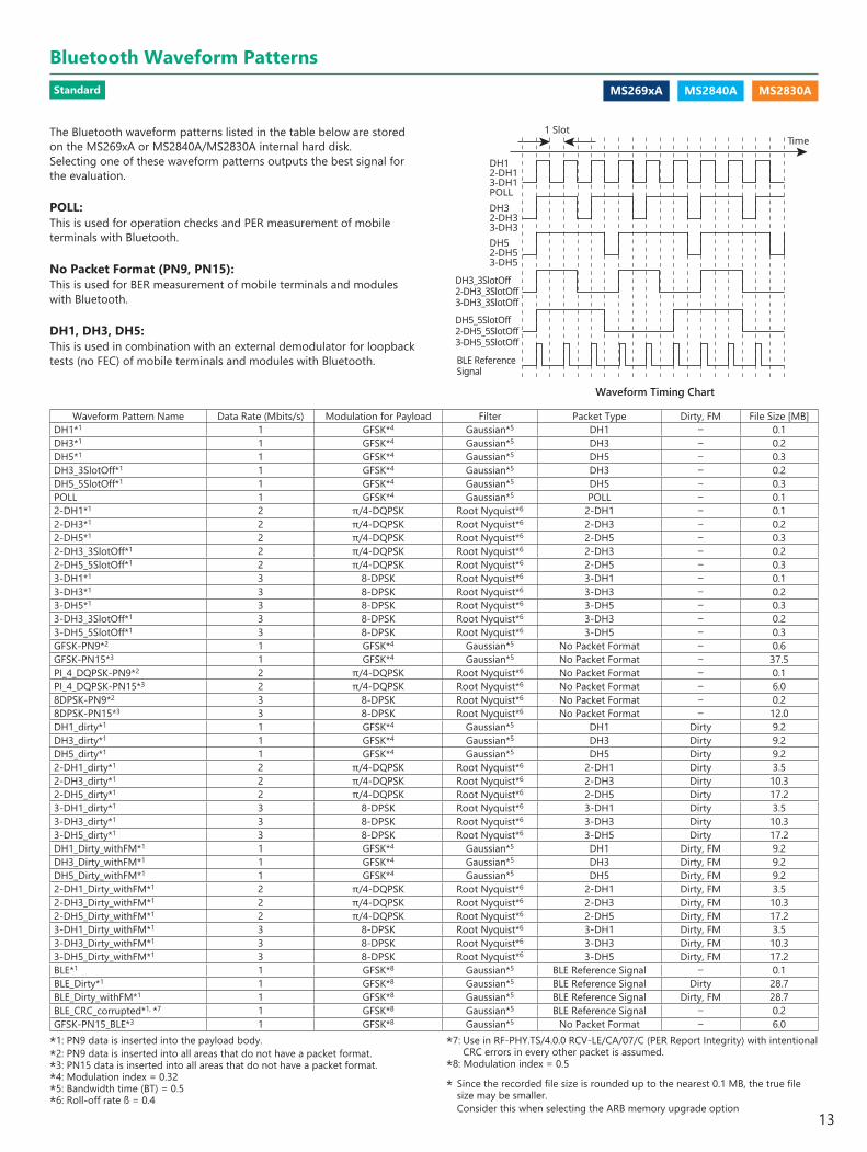
Waveform Timing Chart
The Bluetooth waveform patterns listed in the table below are stored on the MS269xA or MS2840A/MS2830A internal hard disk.Selecting one of these waveform patterns outputs the best signal for the evaluation.
POLL:This is used for operation checks and PER measurement of mobile terminals with Bluetooth.
No Packet Format (PN9, PN15):This is used for BER measurement of mobile terminals and modules with Bluetooth.
DH1, DH3, DH5:This is used in combination with an external demodulator for loopback tests (no FEC) of mobile terminals and modules with Bluetooth.
1 SlotTime
DH3_3SlotOff2-DH3_3SlotOff3-DH3_3SlotOff
DH5_5SlotOff2-DH5_5SlotOff3-DH5_5SlotOff
BLE ReferenceSignal
DH52-DH53-DH5
DH32-DH33-DH3
DH12-DH13-DH1POLL
*1: PN9 data is inserted into the payload body.*2: PN9 data is inserted into all areas that do not have a packet format.*3: PN15 data is inserted into all areas that do not have a packet format.*4: Modulation index = 0.32*5: Bandwidth time (BT) = 0.5*6: Roll-off rate ß = 0.4
Waveform Pattern Name Data Rate (Mbits/s) Modulation for Payload Filter Packet Type Dirty, FM File Size [MB]DH1*1 1 GFSK*4 Gaussian*5 DH1 – 0.1 DH3*1 1 GFSK*4 Gaussian*5 DH3 – 0.2 DH5*1 1 GFSK*4 Gaussian*5 DH5 – 0.3 DH3_3SlotOff*1 1 GFSK*4 Gaussian*5 DH3 – 0.2 DH5_5SlotOff*1 1 GFSK*4 Gaussian*5 DH5 – 0.3 POLL 1 GFSK*4 Gaussian*5 POLL – 0.1 2-DH1*1 2 π/4-DQPSK Root Nyquist*6 2-DH1 – 0.1 2-DH3*1 2 π/4-DQPSK Root Nyquist*6 2-DH3 – 0.2 2-DH5*1 2 π/4-DQPSK Root Nyquist*6 2-DH5 – 0.3 2-DH3_3SlotOff*1 2 π/4-DQPSK Root Nyquist*6 2-DH3 – 0.2 2-DH5_5SlotOff*1 2 π/4-DQPSK Root Nyquist*6 2-DH5 – 0.3 3-DH1*1 3 8-DPSK Root Nyquist*6 3-DH1 – 0.1 3-DH3*1 3 8-DPSK Root Nyquist*6 3-DH3 – 0.2 3-DH5*1 3 8-DPSK Root Nyquist*6 3-DH5 – 0.3 3-DH3_3SlotOff*1 3 8-DPSK Root Nyquist*6 3-DH3 – 0.2 3-DH5_5SlotOff*1 3 8-DPSK Root Nyquist*6 3-DH5 – 0.3 GFSK-PN9*2 1 GFSK*4 Gaussian*5 No Packet Format – 0.6 GFSK-PN15*3 1 GFSK*4 Gaussian*5 No Packet Format – 37.5 PI_4_DQPSK-PN9*2 2 π/4-DQPSK Root Nyquist*6 No Packet Format – 0.1 PI_4_DQPSK-PN15*3 2 π/4-DQPSK Root Nyquist*6 No Packet Format – 6.0 8DPSK-PN9*2 3 8-DPSK Root Nyquist*6 No Packet Format – 0.2 8DPSK-PN15*3 3 8-DPSK Root Nyquist*6 No Packet Format – 12.0 DH1_dirty*1 1 GFSK*4 Gaussian*5 DH1 Dirty 9.2 DH3_dirty*1 1 GFSK*4 Gaussian*5 DH3 Dirty 9.2 DH5_dirty*1 1 GFSK*4 Gaussian*5 DH5 Dirty 9.2 2-DH1_dirty*1 2 π/4-DQPSK Root Nyquist*6 2-DH1 Dirty 3.5 2-DH3_dirty*1 2 π/4-DQPSK Root Nyquist*6 2-DH3 Dirty 10.3 2-DH5_dirty*1 2 π/4-DQPSK Root Nyquist*6 2-DH5 Dirty 17.2 3-DH1_dirty*1 3 8-DPSK Root Nyquist*6 3-DH1 Dirty 3.5 3-DH3_dirty*1 3 8-DPSK Root Nyquist*6 3-DH3 Dirty 10.3 3-DH5_dirty*1 3 8-DPSK Root Nyquist*6 3-DH5 Dirty 17.2 DH1_Dirty_withFM*1 1 GFSK*4 Gaussian*5 DH1 Dirty, FM 9.2 DH3_Dirty_withFM*1 1 GFSK*4 Gaussian*5 DH3 Dirty, FM 9.2 DH5_Dirty_withFM*1 1 GFSK*4 Gaussian*5 DH5 Dirty, FM 9.2 2-DH1_Dirty_withFM*1 2 π/4-DQPSK Root Nyquist*6 2-DH1 Dirty, FM 3.52-DH3_Dirty_withFM*1 2 π/4-DQPSK Root Nyquist*6 2-DH3 Dirty, FM 10.3 2-DH5_Dirty_withFM*1 2 π/4-DQPSK Root Nyquist*6 2-DH5 Dirty, FM 17.2 3-DH1_Dirty_withFM*1 3 8-DPSK Root Nyquist*6 3-DH1 Dirty, FM 3.5 3-DH3_Dirty_withFM*1 3 8-DPSK Root Nyquist*6 3-DH3 Dirty, FM 10.3 3-DH5_Dirty_withFM*1 3 8-DPSK Root Nyquist*6 3-DH5 Dirty, FM 17.2 BLE*1 1 GFSK*8 Gaussian*5 BLE Reference Signal – 0.1 BLE_Dirty*1 1 GFSK*8 Gaussian*5 BLE Reference Signal Dirty 28.7 BLE_Dirty_withFM*1 1 GFSK*8 Gaussian*5 BLE Reference Signal Dirty, FM 28.7 BLE_CRC_corrupted*1, *7 1 GFSK*8 Gaussian*5 BLE Reference Signal – 0.2 GFSK-PN15_BLE*3 1 GFSK*8 Gaussian*5 No Packet Format – 6.0
*7: Use in RF-PHY.TS/4.0.0 RCV-LE/CA/07/C (PER Report Integrity) with intentional CRC errors in every other packet is assumed.
*8: Modulation index = 0.5
* Since the recorded file size is rounded up to the nearest 0.1 MB, the true file size may be smaller. Consider this when selecting the ARB memory upgrade option
Standard
Bluetooth Waveform Patterns
13
MS269xA MS2840A MS2830A
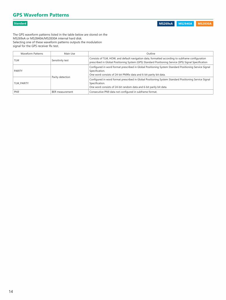
The GPS waveform patterns listed in the table below are stored on the MS269xA or MS2840A/MS2830A internal hard disk.Selecting one of these waveform patterns outputs the modulation signal for the GPS receiver Rx test.
Waveform Patterns Main Use Outline
TLM Sensitivity testConsists of TLM, HOW, and default navigation data, formatted according to subframe configuration prescribed in Global Positioning System (GPS) Standard Positioning Service (SPS) Signal Specification
PARITY
Parity detection
Configured in word format prescribed in Global Positioning System Standard Positioning Service Signal Specification.One word consists of 24-bit PN9fix data and 6-bit parity bit data.
TLM_PARITYConfigured in word format prescribed in Global Positioning System Standard Positioning Service Signal Specification.One word consists of 24-bit random data and 6-bit parity bit data.
PN9 BER measurement Consecutive PN9 data not configured in subframe format.
Standard
GPS Waveform Patterns
14
MS269xA MS2840A MS2830A
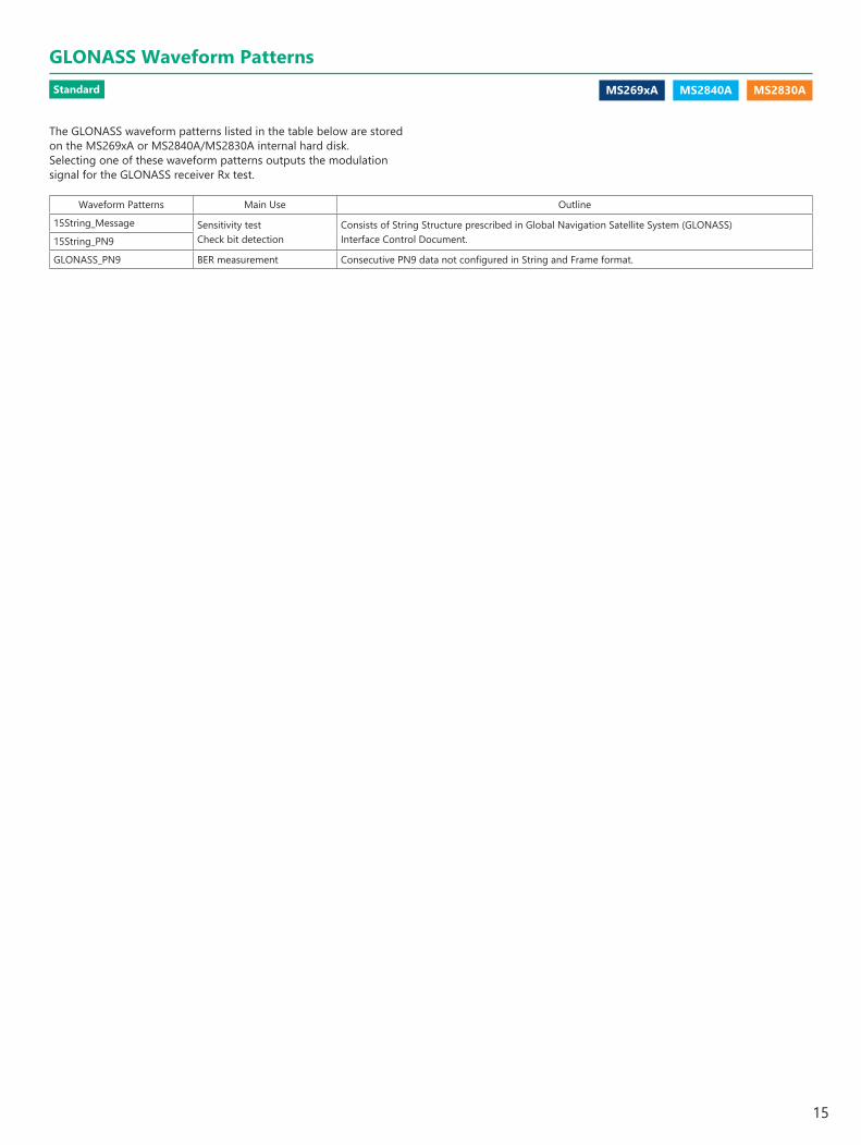
Waveform Patterns Main Use Outline
15String_Message Sensitivity testCheck bit detection
Consists of String Structure prescribed in Global Navigation Satellite System (GLONASS) Interface Control Document.15String_PN9
GLONASS_PN9 BER measurement Consecutive PN9 data not configured in String and Frame format.
The GLONASS waveform patterns listed in the table below are stored on the MS269xA or MS2840A/MS2830A internal hard disk.Selecting one of these waveform patterns outputs the modulation signal for the GLONASS receiver Rx test.
Standard
GLONASS Waveform Patterns
15
MS269xA MS2840A MS2830A
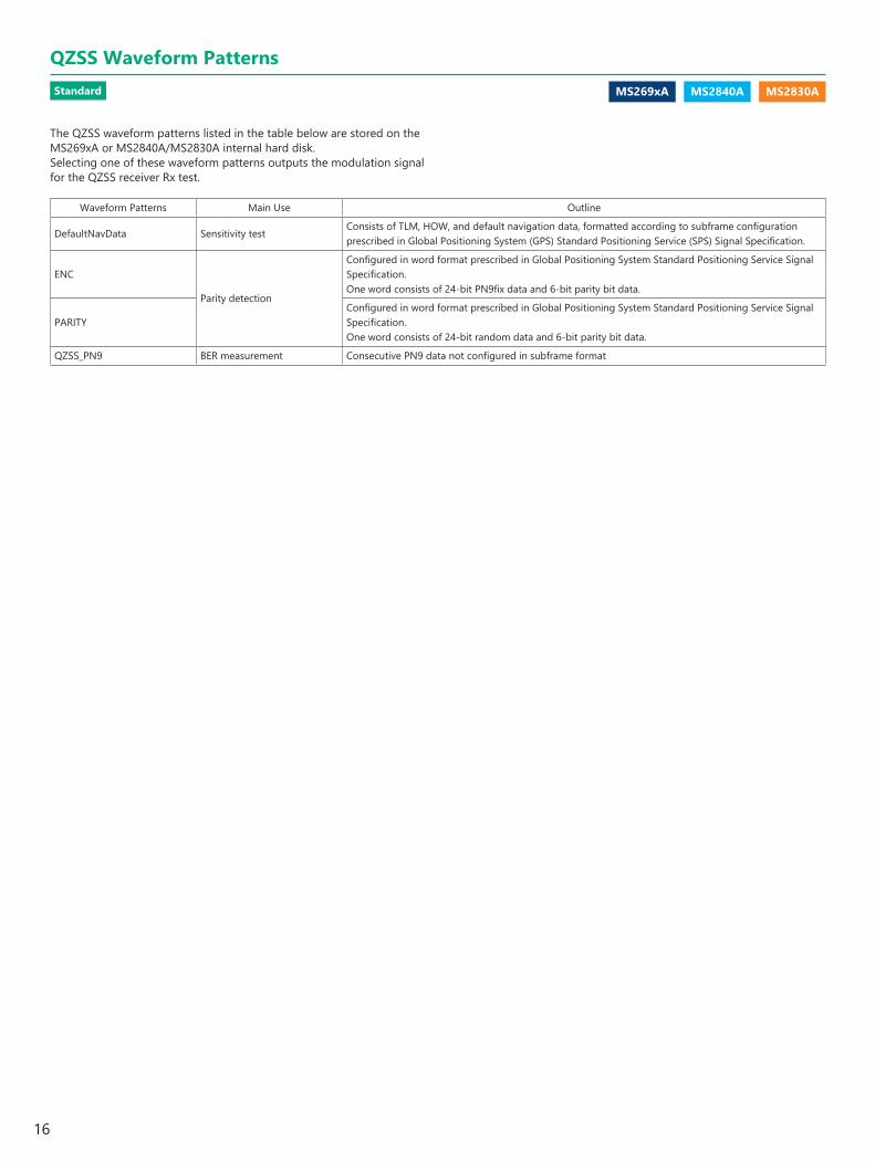
The QZSS waveform patterns listed in the table below are stored on the MS269xA or MS2840A/MS2830A internal hard disk.Selecting one of these waveform patterns outputs the modulation signal for the QZSS receiver Rx test.
Waveform Patterns Main Use Outline
DefaultNavData Sensitivity testConsists of TLM, HOW, and default navigation data, formatted according to subframe configuration prescribed in Global Positioning System (GPS) Standard Positioning Service (SPS) Signal Specification.
ENC
Parity detection
Configured in word format prescribed in Global Positioning System Standard Positioning Service Signal Specification.One word consists of 24-bit PN9fix data and 6-bit parity bit data.
PARITYConfigured in word format prescribed in Global Positioning System Standard Positioning Service Signal Specification.One word consists of 24-bit random data and 6-bit parity bit data.
QZSS_PN9 BER measurement Consecutive PN9 data not configured in subframe format
Standard
QZSS Waveform Patterns
16
MS269xA MS2830A
W-CDMA IQproducer is GUI-based, PC application software for generating waveform patterns used in W-CDMA Rx sensitivity measurement. Once created, the waveform pattern file is downloaded to the MS269xA or MS2830A hard drive. Using the MS269xA-020 or MS2830A-020/021, Vector Signal Generator Option functionality, the files are loaded, selected, and output as a modulated RF signal.By changing the Scrambling Code Number and Channelization Code Number, waveform patterns can be created that support the evaluation of W-CDMA terminals.If complete control of all W-CDMA parameters is required, the HSDPA/HSUPA IQproducer MX269901A software (sold separately) can be used. For details, see the MX269901A section of this document.
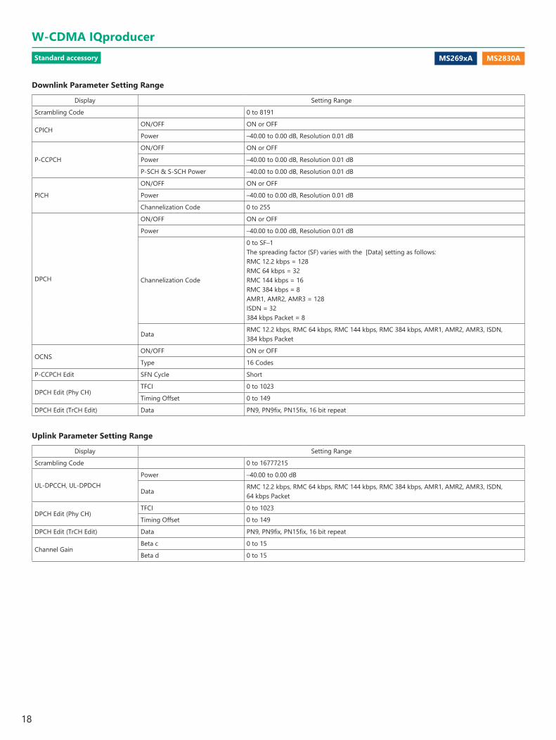
Downlink SettingsDownlink sets parameters including Scrambling code, CPICH/P-CCPCH/PICH/DPCH power, Channelization code, DPCH_PhyCH TFCI and Timing Offset, and DPCH_TrCH Data to create the waveform pattern. (For details, see the Downlink Parameter Setting Range table described later.)Additionally, the Downlink Easy Setup function supports the Reference Measurement Channel (RMC) items specified by 3GPP TS 25.101 and TS 25.104. Parameter setting is easy just by selecting the items to create the waveform pattern.Easy Setup Items include:
RMC 12.2 kbps (Rx test)RMC 12.2 kbps (Performance test)RMC 64 kbps (Performance test)RMC 144 kbps (Performance test)RMC 384 kbps (Performance test)
Downlink Main Screen
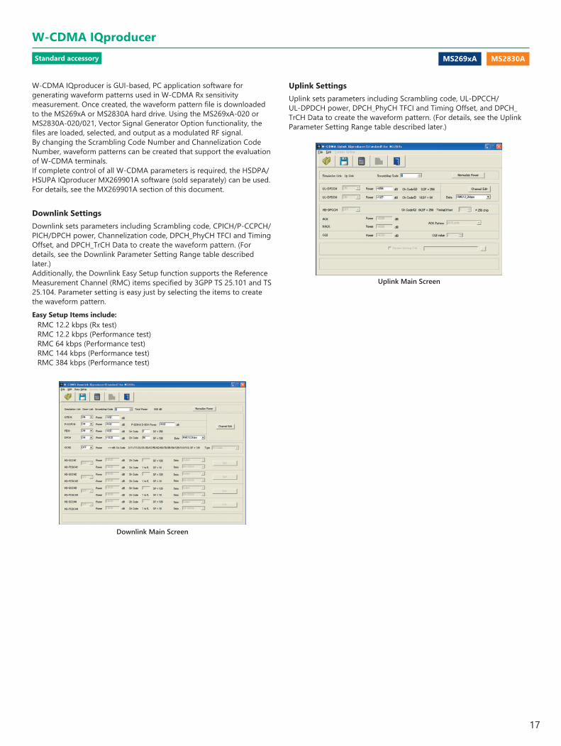
Uplink Main Screen
Uplink SettingsUplink sets parameters including Scrambling code, UL-DPCCH/ UL-DPDCH power, DPCH_PhyCH TFCI and Timing Offset, and DPCH_TrCH Data to create the waveform pattern. (For details, see the Uplink Parameter Setting Range table described later.)
Standard accessory
W-CDMA IQproducer
17
MS269xA MS2830A
Downlink Parameter Setting Range
Display Setting Range
Scrambling Code 0 to 8191
CPICHON/OFF ON or OFF
Power –40.00 to 0.00 dB, Resolution 0.01 dB
P-CCPCH
ON/OFF ON or OFF
Power –40.00 to 0.00 dB, Resolution 0.01 dB
P-SCH & S-SCH Power –40.00 to 0.00 dB, Resolution 0.01 dB
PICH
ON/OFF ON or OFF
Power –40.00 to 0.00 dB, Resolution 0.01 dB
Channelization Code 0 to 255
DPCH
ON/OFF ON or OFF
Power –40.00 to 0.00 dB, Resolution 0.01 dB
Channelization Code
0 to SF–1The spreading factor (SF) varies with the [Data] setting as follows:RMC 12.2 kbps = 128RMC 64 kbps = 32RMC 144 kbps = 16RMC 384 kbps = 8AMR1, AMR2, AMR3 = 128ISDN = 32384 kbps Packet = 8
DataRMC 12.2 kbps, RMC 64 kbps, RMC 144 kbps, RMC 384 kbps, AMR1, AMR2, AMR3, ISDN, 384 kbps Packet
OCNSON/OFF ON or OFF
Type 16 Codes
P-CCPCH Edit SFN Cycle Short
DPCH Edit (Phy CH)TFCI 0 to 1023
Timing Offset 0 to 149
DPCH Edit (TrCH Edit) Data PN9, PN9fix, PN15fix, 16 bit repeat
Uplink Parameter Setting Range
Display Setting Range
Scrambling Code 0 to 16777215
UL-DPCCH, UL-DPDCHPower –40.00 to 0.00 dB
DataRMC 12.2 kbps, RMC 64 kbps, RMC 144 kbps, RMC 384 kbps, AMR1, AMR2, AMR3, ISDN, 64 kbps Packet
DPCH Edit (Phy CH)TFCI 0 to 1023
Timing Offset 0 to 149
DPCH Edit (TrCH Edit) Data PN9, PN9fix, PN15fix, 16 bit repeat
Channel GainBeta c 0 to 15
Beta d 0 to 15
Standard accessory
W-CDMA IQproducer
18
MS269xA MS2830A
This optional GUI-based PC application software is used to set parameters and generate waveform patterns for 3GPP HSDPA/HSUPA (Uplink/Downlink) systems.If complete control of all W-CDMA parameters is required, the HSDPA/HSUPA IQproducer MX269901A software (sold separately) can be used. For details, see the MX269901A section of this document.Once created, the waveform pattern file is downloaded to the MS269xA or MS2830A hard drive. Using the MS269xA-020 or MS2830A-020/021, Vector Signal Generator Option functionality, the files are loaded, selected, and output as a modulated RF signal.The HS-PDSCH and HS-DPCCH parameters specified in TS 25.212 can be set. The Downlink Easy Setup function assigns default values to some parameters and sets other items to typical values, making the creation of an accurate waveform pattern fast and easy.
Downlink SettingsVarious downlink parameters can be set. (For details, see the Downlink Parameter Setting table described later.)The Downlink Easy Setup function supports the HSDPA Fixed Reference Channel (FRC) items specified in 3GPP TS 25.101, and the Reference Measurement Channel (RMC) items specified in 3GPP TS 25.101 and TS 25.104.Easy Setup Items include:
FRC: H-Set1 (QPSK) H-Set1 (16QAM) H-Set2 (QPSK) H-Set2 (16QAM) H-Set3 (QPSK) H-Set3 (16QAM) H-Set4 H-Set5
RMC: RMC 12.2 kbps (Rx test) RMC 12.2 kbps (Performance test) RMC 64 kbps (Performance test) RMC 144 kbps (Performance test) RMC 384 kbps (Performance test)
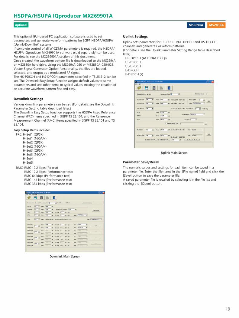
Uplink SettingsUplink sets parameters for UL-DPCCH/UL-DPDCH and HS-DPCCH channels and generates waveform patterns.(For details, see the Uplink Parameter Setting Range table described later).
HS-DPCCH (ACK, NACK, CQI)UL-DPCCHUL-DPDCHE-DPCCHE-DPDCH (s)
Downlink Main Screen
Uplink Main Screen
Parameter Save/RecallThe numeric values and settings for each item can be saved in a parameter file. Enter the file name in the [File name] field and click the [Save] button to save the parameter file. A saved parameter file is recalled by selecting it in the file list and clicking the [Open] button.
Optional
HSDPA/HSUPA IQproducer MX269901A
19

MS269xA MS2830A
Downlink Parameter Setting RangeDisplay Setting Range
Scrambling Code 0 to 8191
CPICHON/OFF ON or OFFPower –40.00 to 0.00 dB, Resolution 0.01 dB
P-CCPCHON/OFF ON or OFFPower –40.00 to 0.00 dB, Resolution 0.01 dBP-SCH & S-SCH Power –40.00 to 0.00 dB, Resolution 0.01 dB
PICHON/OFF ON or OFFPower –40.00 to 0.00 dB, Resolution 0.01 dBChannelization Code 0 to 255
DPCH
ON/OFF ON or OFFPower –40.00 to 0.00 dB, Resolution 0.01 dB
Channelization Code
0 to SF–1 The spreading factor (SF) varies with the [Data] setting as follows:• RMC 12.2 kbps = 128 • RMC 64 kbps = 32• RMC 144 kbps = 16 • RMC 384 kbps = 8• AMR1, AMR2, AMR3 = 128 • ISDN = 32 • 384 kbps Packet = 8• User Edit TrCH = Spreading Factor of Channel Edit screen
DataRMC 12.2 kbps, RMC 64 kbps, RMC 144 kbps, RMC 384 kbps, AMR1, AMR2, AMR3, ISDN, 384 kbps Packet, User Edit TrCH
OCNSON/OFF ON or OFFType 16 Codes or 6 Codes (ch = 122 to 127) or 6 Codes (ch = 2 to 7)
HS-SCCH1/2/3/4
ON/OFF ON or OFFPower –40.00 to 0.00 dB, Resolution 0.01 dBChannelization Code 0 to 127Data PN9, PN9fix, PN15fix, 16 bit repeat, Coded
HS-PDSCH1/2/3/4
ON/OFF ON or OFFPower –40.00 to 0.00 dB, Resolution 0.01 dBChannelization Code 0 to 15Data PN9, PN9fix, PN15fix, 16 bit repeat, HS-DSCH
P-CCPCH Edit SFN Cycle Short
DPCH Edit (Phy CH)
DPCH Data PN9, PN9fix, PN15fix, 16 bit repeat, TrCHTFCI 0 to 1023Spreading Factor 4, 8, 16, 32, 64, 128, 256, 512BER 0.0 to 100.0%Slot Format #0 to #16Timing Offset 0 to 149
TPC Edit0000 0000 0000 0000 0000 0000 0000 0000 0000 0000 0000 0000 0000 0000 0000 to 1111 1111 1111 1111 1111 1111 1111 1111 1111 1111 1111 1111 1111 1111 1111
DPCH Edit (TrCH Edit)
TrCH Number 1 to 8DTX Fix/FlexData PN9, PN9fix, PN15fix, 16 bit repeatTTI 10, 20, 40, 80 msMax. TrBk Size 0 to 5000TrBk Size 0 to 5000Max. TrBk Set No. 0 to 64TrBk Set No. 0 to 64CRC 0, 8, 12, 16, 24 bitCoder CC1/2, CC1/3, TCRM attribute 1 to 256BER 0.0 to 100.0%BLER 0 to 100%
HSDPA transport channel(HS-SCCH, HS-PDSCH parameters)
Channelization Code Offset 1 to (16–Number of Physical Channel Code)Number of Physical Channel Code 1 to (16–Channelization Code Offset)Modulation QPSK or 16QAMTransport Block Size Information 0 to 63RV Information 0 to 7UE Identity 0 to 65535CRC Error Insertion Correct or FailNumber of HARQ Processes 0 to 8Virtual IR Buffer Size 800 to 304000Payload Data PN9, PN9fix, PN15fix, 16 bit repeat
Transmitting Pattern Edit
HARQ Process Cycle 1 to 16 (Note ranges from 1 to 6 when PN9 set for Payload Data)Inter-TTI Distance 1 to 8TTI Start Offset 0 to 7Process Setting File Used or Not used
Optional
HSDPA/HSUPA IQproducer MX269901A
20
MS269xA MS2830A
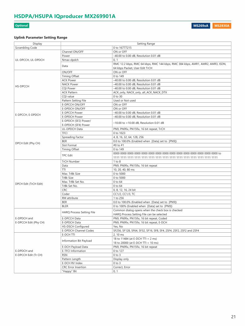
Uplink Parameter Setting RangeDisplay Setting Range
Scrambling Code 0 to 16777215
UL-DPCCH, UL-DPDCH
Channel ON/OFF ON or OFFPower –40.00 to 0.00 dB, Resolution 0.01 dBNmax-dpdch 0, 1
DataRMC 12.2 kbps, RMC 64 kbps, RMC 144 kbps, RMC 384 kbps, AMR1, AMR2, AMR3, ISDN, 64 kbps Packet, User Edit TrCH
HS-DPCCH
ON/OFF ON or OFFTiming Offset 0 to 149ACK Power –40.00 to 0.00 dB, Resolution 0.01 dBNACK Power –40.00 to 0.00 dB, Resolution 0.01 dBCQI Power –40.00 to 0.00 dB, Resolution 0.01 dBACK Pattern ACK_only, NACK_only, alt_ACK_NACK_DTXCQI value 0 to 30Pattern Setting File Used or Not used
E-DPCCH, E-DPDCH
E-DPCCH ON/OFF ON or OFFE-DPDCH ON/OFF ON or OFFE-DPCCH Power –40.00 to 0.00 dB, Resolution 0.01 dBE-DPDCH Power –40.00 to 0.00 dB, Resolution 0.01 dBE-DPDCH (SF2) Power/E-DPDCH (SF4) Power
–10.00 to +10.00 dB, Resolution 0.01 dB
DPCH Edit (Phy CH)
UL-DPDCH Data PN9, PN9fix, PN15fix, 16 bit repeat, TrCHTFCI 0 to 1023Spreading Factor 4, 8, 16, 32, 64, 128, 256BER 0.0 to 100.0% (Enabled when [Data] set to [PN9])Slot Format #0 to #1Timing Offset 0 to 149
TPC Edit0000 0000 0000 0000 0000 0000 0000 0000 0000 0000 0000 0000 0000 0000 0000 to 1111 1111 1111 1111 1111 1111 1111 1111 1111 1111 1111 1111 1111 1111 1111
DPCH Edit (TrCH Edit)
TrCH Number 1 to 8Data PN9, PN9fix, PN15fix, 16 bit repeatTTI 10, 20, 40, 80 msMax. TrBk Size 0 to 5000TrBk Size 0 to 5000Max. TrBk Set No. 0 to 64TrBk Set No. 0 to 64CRC 0, 8, 12, 16, 24 bitCoder CC1/2, CC1/3, TCRM attribute 1 to 256BER 0.0 to 100.0% (Enabled when [Data] set to [PN9])BLER 0 to 100% (Enabled when [Data] set to [PN9])
E-DPDCH andE-DPCCH Edit (Phy CH)
HARQ Process Setting FileCommon dialog opens when the check box is checkedHARQ Process Setting File can be selected
E-DPCCH Data PN9, PN9fix, PN15fix, 16 bit repeat, CodedE-DPDCH Data PN9, PN9fix, PN15fix, 16 bit repeat, E-DCHHS-DSCH Configured Yes, NoE-DPDCH Channel Codes SF256, SF128, SF64, SF32, SF16, SF8, SF4, 2SF4, 2SF2, 2SF2 and 2SF4
E-DPDCH andE-DPCCH Edit (Tr CH)
E-DCH TTI 2, 10 ms
Information Bit Payload18 to 11484 (at E-DCH TTI = 2 ms)18 to 20000 (at E-DCH TTI = 10 ms)
E-DCH Payload Data PN9, PN9fix, PN15fix, 16 bit repeatE-TFCI Information 0 to 127RSN 0 to 3Pattern Length Display onlyE-DCH RV Index 0 to 3CRC Error Insertion Correct, Error"Happy" Bit 0, 1
Optional
HSDPA/HSUPA IQproducer MX269901A
21
MS269xA MS2840A MS2830A
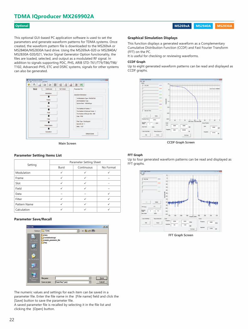
This optional GUI-based PC application software is used to set the parameters and generate waveform patterns for TDMA systems. Once created, the waveform pattern file is downloaded to the MS269xA or MS2840A/MS2830A hard drive. Using the MS269xA-020 or MS2840A/MS2830A-020/021, Vector Signal Generator Option functionality, the files are loaded, selected, and output as a modulated RF signal. In addition to signals supporting PDC, PHS, ARIB STD-T61/T79/T86/T98/T102, Advanced-PHS, ETC and DSRC systems, signals for other systems can also be generated.
Main Screen
Parameter Setting Items List
SettingParameter Setting Sheet
Burst Continuous No Format
Modulation
Frame –
Slot –
Field –
Data – –
Filter
Pattern Name
Calculation
Parameter Save/Recall
The numeric values and settings for each item can be saved in a parameter file. Enter the file name in the [File name] field and click the [Save] button to save the parameter file. A saved parameter file is recalled by selecting it in the file list and clicking the [Open] button.
Graphical Simulation DisplaysThis function displays a generated waveform as a Complementary Cumulative Distribution Function (CCDF) and Fast Fourier Transform (FFT) on the PC.It is useful for checking or reviewing waveforms.CCDF GraphUp to eight generated waveform patterns can be read and displayed as CCDF graphs.
CCDF Graph Screen
FFT Graph Screen
FFT GraphUp to four generated waveform patterns can be read and displayed as FFT graphs.
Optional
TDMA IQproducer MX269902A
22

MS269xA MS2840A MS2830A
Guard Field Setting Range(1st/2nd) Modulation Type Number of Bits in 1st Field Number of Bits in 24th Field
BPSK, DBPSK, PI/2DBPSK, ASK, 2FSK Integer between 0 and 9960 Integer between 0 and 9960QPSK, O-QPSK, DQPSK, PI/4DQPSK, 4FSK, 4ASK Multiples of 2 between 0 and 9960 Multiples of 2 between 0 and 99608PSK, D8PSK Multiples of 3 between 0 and 9960 Multiples of 3 between 0 and 996016QAM Multiples of 4 between 0 and 9960 Multiples of 4 between 0 and 996032QAM Multiples of 5 between 0 and 9960 Multiples of 5 between 0 and 996064QAM Multiples of 6 between 0 and 9960 Multiples of 6 between 0 and 9960256QAM Multiples of 8 between 0 and 9960 Multiples of 8 between 0 and 9960
Ramp Field Setting Range(1st/2nd) Modulation Type Number of Bits
BPSK, DBPSK, PI/2DBPSK, ASK, 2FSK Integer number between 1 and 16QPSK, O-QPSK, DQPSK, PI/4DQPSK, 4FSK, 4ASK Multiples of 2 between 2 and 328PSK, D8PSK Multiples of 3 between 3 and 4816QAM Multiples of 4 between 4 and 6432QAM Multiples of 5 between 5 and 8064QAM Multiples of 6 between 6 and 96256QAM Multiples of 8 between 8 and 128
Parameter Setting Items ListItems Display Outline Setting Range
Modulation
Modulation Type(1st Modulation Type) 1st Modulation Type BPSK, DBPSK, PI/2DBPSK, QPSK, O-QPSK, DQPSK, PI/4DQPSK, 8PSK*1, D8PSK*1,
16QAM*1, 32QAM*1, 64QAM*1, 256QAM*1, ASK, 2FSK, 4FSK, 4ASKModulation Type(2nd Modulation Type) 2nd Modulation Type BPSK, DBPSK, PI/2DBPSK, QPSK, DQPSK, PI/4DQPSK, 8PSK, D8PSK, 16QAM,
32QAM, 64QAM, 256QAMSymbol Rate Symbol Rate 1 ksps to 80 Msps (can be set in the 1 sps units)Over Sampling Over Sampling Rate 2, 3, 4, 8, 16, 32
Sampling Rate Sampling Rate20 kHz to 160 MHz (The value of symbol rate × over sampling rate is set automatically. However, when the Manchester code setting enabled, the value of symbol rate × over sampling rate × 2 is set automatically)
GSM GSM Setting Enable/disable automatic setting in accordance with GSM(Enabled when 8PSK or 2FSK set as modulation type)
Modulation Index Modulation Index 0.00 to 1.00 (for ASK), 0.20 to 10.00 (for 2FSK)
Manchester Code Manchester CodeThe Manchester code is selected when this checkbox is selected, and NRZ is selected when this checkbox is cleared. NRZ is always selected for modulation types other than ASK
Maximum Frequency Deviation Maximum frequency deviation 120 to 2100
FrameThe Number of Frames Frame number 1 to 4088, AutoThe Number of Slots per Frame Slot numbers in one frame 1 to 20
Slot (Burst)
1, 24 field Guard field Set the number of bits listed in the separate table according to Modulation Type.
2, 23 field Ramp field Set the number of bits listed in the separate table according to Modulation Type.
3 to 22 field Fixed (Fixed data) field Set integer from 0 to 128.3 to 22 field Data (PN9, PN15) field Set integer from 0 to 1024.
4 to 22 field CRC (Cyclic Redundancy Check character) field 0, 8, 12, 16, 24, 32
Slot (Continuous)
1 to 24 field Fixed (Fixed data) field Set integer from 0 to 128.1 to 24 field Data (PN9, PN15) field Set integer from 0 to 1024.
2 to 24 field CRC (Cyclic Redundancy Check character) field 0, 8, 12, 16, 24, 32
Field(Burst/Continuous)
Fixed Sets hexadecimal fixed data 0 to maximum value of number of bits setCRC Sets CRC calculation field as integer 1 to number of bits in field on left to CRC (except Guard and Ramp fields)
Data Field Selects continuous pattern PN9, PN15, 16 bit Pattern, All 0, All 1, UserFile*2
Input any hexadecimal number for 16 bit Pattern.Data (No Format) Data Selects continuous pattern PN9, PN15, 16 bit Pattern, All 0, All 1, UserFile*2
Filter
Filter Filter type Nyquist, Root Nyquist, Gaussian, Gaussian2, Ideal Lowpass, None, ARIB STD-T98, ARIB STD-T102 Part1, Half-sine, User Defined Filter
Roll Off/BT Roll off rate/BT product 0.10 to 1.00 (When Nyquist/Root Nyquist/Gaussian is set)
Passband Passband of filterFs/2, Fs/3, Fs/4, Fs/8, Fs/16, Fs/32(This item is displayed and can be set only when Ideal Lowpass is set as the filter type. The setting range varies with the over sampling rate)
RMS RMS value of waveform pattern data 1157
Pattern NamePackage Package name Within 31 charactersPattern Name Waveform pattern file name Within 20 charactersComment Comment Within 38 characters
Calculation Starts waveform pattern data generation after setting parameters.
*1: Decimal numbers for each symbol point are changed by selecting a user file for IQ mapping.*2: When "UserFile" is set, the binary sequence is read from a text file. Up to 9,600,000 bits can be loaded and then modulated.
Optional
TDMA IQproducer MX269902A
23

MS269xA MS2840A MS2830A
This GUI-driven PC application software is used to create a multi-carrier waveform pattern for modulated signals and tone signals of communications systems. Once created, the waveform pattern file is downloaded to the MS269xA or MS2840A/MS2830A hard drive. Using the MS269xA-020 or MS2840A/MS2830A-020/021, Vector Signal Generator Option functionality, the files are loaded, selected, and output as a multi-carrier RF signal. W-CDMA downlink multi-carrier signals are supported as well as various types of clipping.
Multi-purpose FunctionBy using the multi-carrier function, a signal with up to 32 carriers can be converted to a single waveform pattern. While it may not be possible to set 32 carriers due to the frequency offset and the waveform pattern, it is possible to create a waveform pattern with more than 32 carriers by combining multi-carrier waveform patterns.Ex) 10 MHz Bandwidth WiMAX × 2 carrier
Multi-carrier Setting Screen
FFT Analysis Screen
Multi-carrier Setting Screen
Multi-carrier Setting Screen
W-CDMA (DL) FunctionThis function is used to create a waveform pattern by setting any of the 4 or 5 carriers of the W-CDMA Downlink ON/OFF, as well as by setting the Clipping Method, Clipping Reference Level, and Clipping Ratio.
Carrier TypeTest Model 1 16DPCH, Test Model 1 32DPCH, Test Model 1 64DPCH, Test Model 5 2HS-PDSCH, Test Model 5 4HS-PDSCH, Test Model 5 8HS-PDSCH
Clipping Method
Non, Vector (pre-filter), Vector (post-filter), Scalar (pre-filter), Scalar (post-filter)
Clipping Reference levelPeak Power, RMS Power
Optional
Multi-Carrier IQproducer MX269904A
24

MS269xA MS2830A
Modulation
Filter
FRC (UL) by Signal Type
E-UTRA Test Models by Signal TypeBandwidth
Data
Test Type
Easy Setup Screen (Example: FRC_UL)
System
The LTE IQproducer MX269908A is PC application software with a GUI for generating waveform patterns in compliance with the LTE FDD specifications in the 3GPP TS 36.211, TS 36.212, and TS 36.213 standards.Generates test model waveform patterns used for LTE base station Tx tests and FRC (Fixed Reference Channel) used for Rx tests. LTE IQproducer supports two setting screens: “Easy Setup Screen” and “Normal Setup Screen”.The LTE-Advanced FDD option MX269908A-001 supports simple generation of carrier aggregation signals added* by 3GPP Rel. 10.Additionally, clustered SC-FDMA signals can be generated at Uplink.
*: MBSFN reference signals, UE-specific reference signals, Positioning reference signals, CSI reference signals, and Physical Multicast Channel are not supported.
Easy Setup ScreenWaveform patterns can be generated easily because the main parameters are restricted to the Easy Setup screen.Use “Normal Setup function” for detailed parameter settings.
Channels Generated by MX269908ADownlink
Cell-specific Reference SignalPrimary Synchronization SignalSecondary Synchronization SignalPBCH (Physical Broadcast Channel)PCFICH (Physical Control Format Indicator Channel)PDCCH (Physical Downlink Control Channel)PDSCH (Physical Downlink Shared Channel)PHICH (Physical Hybrid-ARQ Indicator Channel)
UplinkPUCCH (Physical Uplink Control Channel)PUSCH (Physical Uplink Shared Channel)Demodulation Reference Signal for PUCCH/PUSCHSounding Reference SignalRandom Access Preamble
Optional
LTE IQproducer MX269908A/LTE-Advanced FDD Option MX269908A-001
25
MS269xA MS2830A
BS Test/E-UTRA Test Models
BS Test/FRC
UE Test/RMC (DL)/FRC
UE Test/RMC (UL)
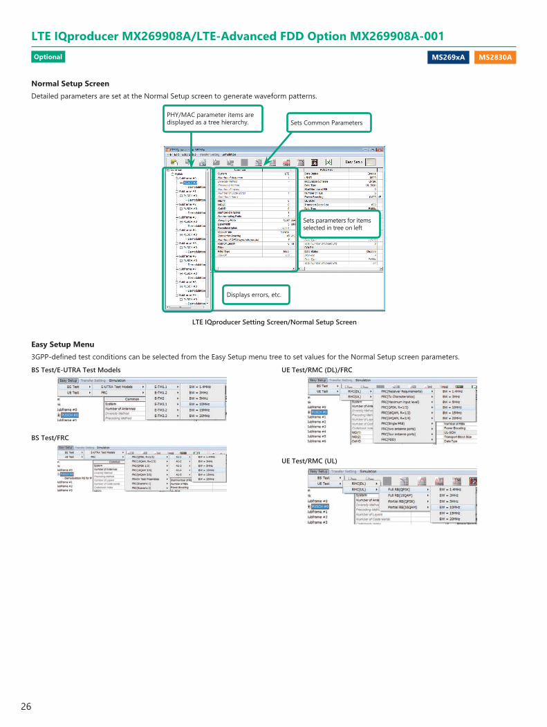
LTE IQproducer Setting Screen/Normal Setup Screen
PHY/MAC parameter items are displayed as a tree hierarchy. Sets Common Parameters
Displays errors, etc.
Sets parameters for items selected in tree on left
Normal Setup ScreenDetailed parameters are set at the Normal Setup screen to generate waveform patterns.
Easy Setup Menu3GPP-defined test conditions can be selected from the Easy Setup menu tree to set values for the Normal Setup screen parameters.
Optional
LTE IQproducer MX269908A/LTE-Advanced FDD Option MX269908A-001
26
MS269xA MS2830A
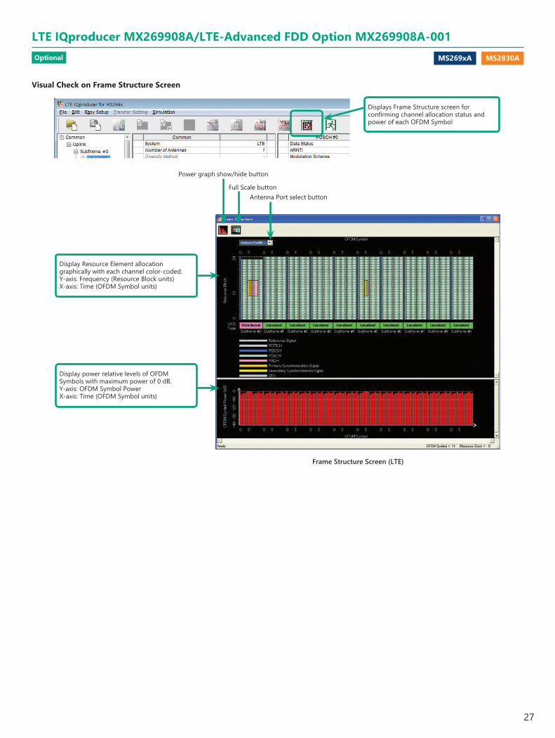
Visual Check on Frame Structure Screen
Displays Frame Structure screen for confirming channel allocation status and power of each OFDM Symbol
Frame Structure Screen (LTE)
Display Resource Element allocation graphically with each channel color-coded.Y-axis: Frequency (Resource Block units)X-axis: Time (OFDM Symbol units)
Display power relative levels of OFDM Symbols with maximum power of 0 dB.Y-axis: OFDM Symbol PowerX-axis: Time (OFDM Symbol units)
Power graph show/hide button
Full Scale buttonAntenna Port select button
Optional
LTE IQproducer MX269908A/LTE-Advanced FDD Option MX269908A-001
27

MS269xA MS2830A
LTE-Advanced Easy Setup Screen (Example: FRC (UL))
FRC (UL) Setup Screen E-UTRA Test Models Setup Screen
Carrier Aggregation Mode
Test Type
System
Component Carrier SetupIntra-band
Component Carrier: #0 to #4Inter-band
Band #0, #1Component Carrier: #0 to #4
[Setup Item] StatusBandwidthCell IDGainFrequency OffsetPhaseDelay
LTE-Advanced FDD Option MX269908A-001
Adding the LTE-Advanced FDD Option MX269908A-001 to set LTE-Advanced system parameters supports generation of carrier aggregation signals added* by 3GPP Rel. 10.Additionally, clustered SC-FDMA signals can be generated at Uplink.
*: MBSFN reference signals, UE-specific reference signals, Positioning reference signals, CSI reference signals, and Physical Multicast Channel are not supported.
Easy Setup ScreenWaveform patterns can be generated easily by setting the band matching the carrier aggregation mode and component carrier because the main parameters are restricted to the Easy Setup screen.Use the “Normal Setup Function” for detailed parameter settings.
LTE-Advanced Setting ParametersCarrier Aggregation ModeIntra-band
Component Carrier: #0 to #4
Inter-bandBand #0, #1Component Carrier: #0 to #4
Optional
LTE IQproducer MX269908A/LTE-Advanced FDD Option MX269908A-001
28
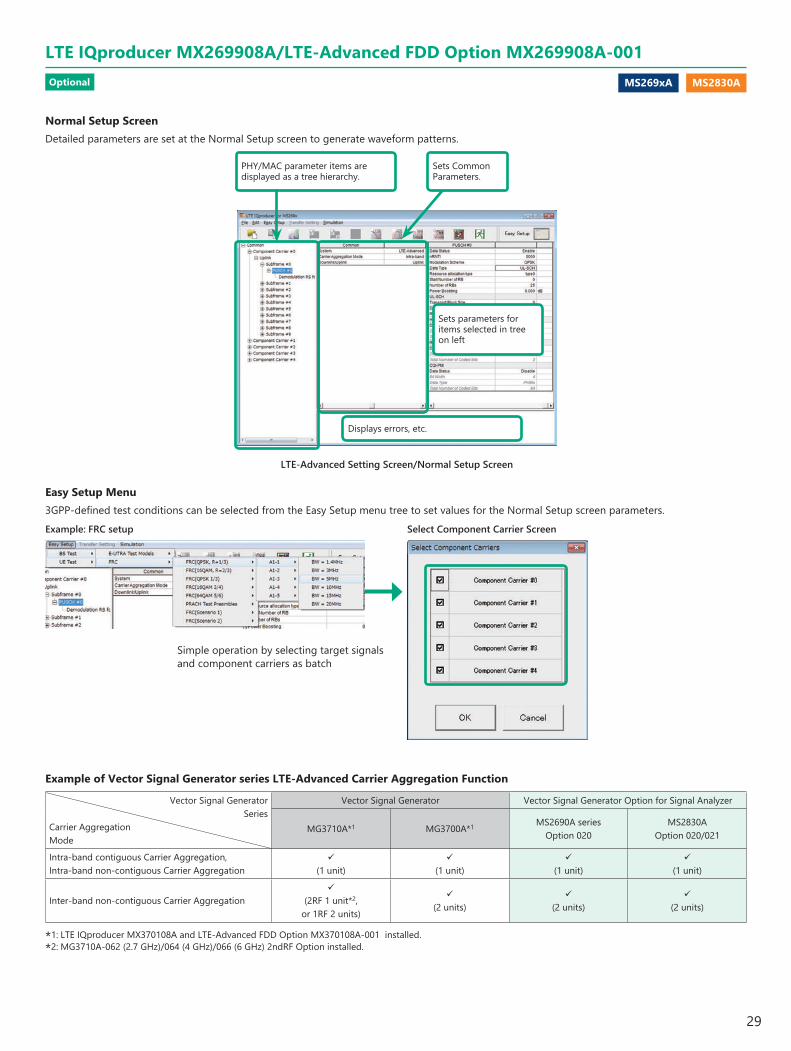
MS269xA MS2830A
PHY/MAC parameter items are displayed as a tree hierarchy.
Sets Common Parameters.
Displays errors, etc.
Sets parameters for items selected in tree on left
LTE-Advanced Setting Screen/Normal Setup Screen
Simple operation by selecting target signals and component carriers as batch
Example of Vector Signal Generator series LTE-Advanced Carrier Aggregation Function
Vector Signal Generator Series
Carrier AggregationMode
Vector Signal Generator Vector Signal Generator Option for Signal Analyzer
MG3710A*1 MG3700A*1 MS2690A seriesOption 020
MS2830AOption 020/021
Intra-band contiguous Carrier Aggregation, Intra-band non-contiguous Carrier Aggregation
(1 unit)
(1 unit)
(1 unit)
(1 unit)
Inter-band non-contiguous Carrier Aggregation
(2RF 1 unit*2, or 1RF 2 units)
(2 units)
(2 units)
(2 units)
*1: LTE IQproducer MX370108A and LTE-Advanced FDD Option MX370108A-001 installed.*2: MG3710A-062 (2.7 GHz)/064 (4 GHz)/066 (6 GHz) 2ndRF Option installed.
Select Component Carrier ScreenExample: FRC setup
Normal Setup ScreenDetailed parameters are set at the Normal Setup screen to generate waveform patterns.
Easy Setup Menu3GPP-defined test conditions can be selected from the Easy Setup menu tree to set values for the Normal Setup screen parameters.
Optional
LTE IQproducer MX269908A/LTE-Advanced FDD Option MX269908A-001
29

MS269xA MS2830A
Display Resource Element allocation graphically with each channel color-coded.Y-axis: Frequency (Resource Block units)X-axis: Time (OFDM Symbol units)
Display power relative levels of OFDM Symbols with maximum power of 0 dB.Y-axis: OFDM Symbol PowerX-axis: Time (OFDM Symbol units)
Power graph show/hide button
Band select buttonFull Scale button Component Carrier select button
Antenna Port select button
Frame Structure Screen (LTE-Advanced)
Visual Check on Frame Structure Screen
Displays Frame Structure screen for confirming channel allocation status and power of each OFDM Symbol
Optional
LTE IQproducer MX269908A/LTE-Advanced FDD Option MX269908A-001
30
MS269xA MS2830A
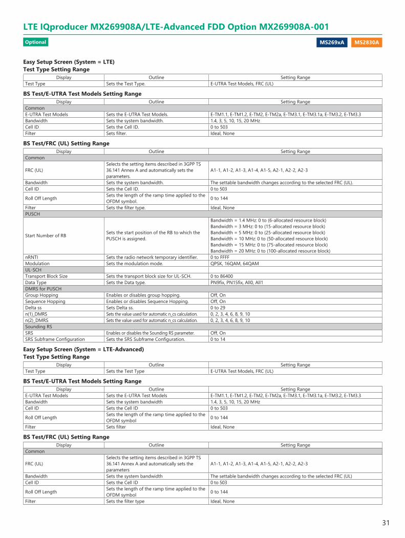
Easy Setup Screen (System = LTE) Test Type Setting Range
Display Outline Setting RangeTest Type Sets the Test Type. E-UTRA Test Models, FRC (UL)
BS Test/E-UTRA Test Models Setting RangeDisplay Outline Setting Range
CommonE-UTRA Test Models Sets the E-UTRA Test Models. E-TM1.1, E-TM1.2, E-TM2, E-TM2a, E-TM3.1, E-TM3.1a, E-TM3.2, E-TM3.3Bandwidth Sets the system bandwidth. 1.4, 3, 5, 10, 15, 20 MHzCell ID Sets the Cell ID. 0 to 503Filter Sets filter. Ideal, None
BS Test/FRC (UL) Setting RangeDisplay Outline Setting Range
Common
FRC (UL)Selects the setting items described in 3GPP TS 36.141 Annex A and automatically sets the parameters.
A1-1, A1-2, A1-3, A1-4, A1-5, A2-1, A2-2, A2-3
Bandwidth Sets the system bandwidth. The settable bandwidth changes according to the selected FRC (UL).Cell ID Sets the Cell ID. 0 to 503
Roll Off Length Sets the length of the ramp time applied to the OFDM symbol. 0 to 144
Filter Sets the filter type. Ideal, NonePUSCH
Start Number of RB Sets the start position of the RB to which the PUSCH is assigned.
Bandwidth = 1.4 MHz: 0 to (6-allocated resource block)Bandwidth = 3 MHz: 0 to (15-allocated resource block)Bandwidth = 5 MHz: 0 to (25-allocated resource block)Bandwidth = 10 MHz: 0 to (50-allocated resource block)Bandwidth = 15 MHz: 0 to (75-allocated resource block)Bandwidth = 20 MHz: 0 to (100-allocated resource block)
nRNTI Sets the radio network temporary identifier. 0 to FFFFModulation Sets the modulation mode. QPSK, 16QAM, 64QAMUL-SCHTransport Block Size Sets the transport block size for UL-SCH. 0 to 86400Data Type Sets the Data type. PN9fix, PN15fix, All0, All1DMRS for PUSCHGroup Hopping Enables or disables group hopping. Off, OnSequence Hopping Enables or disables Sequence Hopping. Off, OnDelta ss Sets Delta ss. 0 to 29n(1)_DMRS Sets the value used for automatic n_cs calculation. 0, 2, 3, 4, 6, 8, 9, 10n(2)_DMRS Sets the value used for automatic n_cs calculation. 0, 2, 3, 4, 6, 8, 9, 10Sounding RSSRS Enables or disables the Sounding RS parameter. Off, OnSRS Subframe Configuration Sets the SRS Subframe Configuration. 0 to 14
Easy Setup Screen (System = LTE-Advanced) Test Type Setting Range
Display Outline Setting RangeTest Type Sets the Test Type E-UTRA Test Models, FRC (UL)
BS Test/E-UTRA Test Models Setting RangeDisplay Outline Setting Range
E-UTRA Test Models Sets the E-UTRA Test Models E-TM1.1, E-TM1.2, E-TM2, E-TM2a, E-TM3.1, E-TM3.1a, E-TM3.2, E-TM3.3Bandwidth Sets the system bandwidth 1.4, 3, 5, 10, 15, 20 MHzCell ID Sets the Cell ID 0 to 503
Roll Off Length Sets the length of the ramp time applied to the OFDM symbol 0 to 144
Filter Sets filter Ideal, None
BS Test/FRC (UL) Setting RangeDisplay Outline Setting Range
Common
FRC (UL)Selects the setting items described in 3GPP TS 36.141 Annex A and automatically sets the parameters
A1-1, A1-2, A1-3, A1-4, A1-5, A2-1, A2-2, A2-3
Bandwidth Sets the system bandwidth The settable bandwidth changes according to the selected FRC (UL)Cell ID Sets the Cell ID 0 to 503
Roll Off Length Sets the length of the ramp time applied to the OFDM symbol 0 to 144
Filter Sets the filter type Ideal, None
LTE IQproducer MX269908A/LTE-Advanced FDD Option MX269908A-001Optional
31

MS269xA MS2830A
Display Outline Setting RangePUSCH
Start Number of RB Sets the start position of the RB to which the PUSCH is assigned
Bandwidth = 1.4 MHz: 0 to (6-allocated resource block) Bandwidth = 3 MHz: 0 to (15-allocated resource block) Bandwidth = 5 MHz: 0 to (25-allocated resource block) Bandwidth = 10 MHz: 0 to (50-allocated resource block) Bandwidth = 15 MHz: 0 to (75-allocated resource block) Bandwidth = 20 MHz: 0 to (100-allocated resource block)
nRNTI Sets the radio network temporary identifier 0 to FFFFModulation Sets the modulation mode QPSK, 16QAM, 64QAMUL-SCHTransport Block Size Sets the transport block size for UL-SCH 0 to 86400Data Type Sets the Data type PN9fix, PN15fix, All0, All1DMRS for PUSCHGroup Hopping Enables or disables group hopping Off, OnSequence Hopping Enables or disables Sequence Hopping Off, OnDelta ss Sets Delta ss 0 to 29n (1)_DMRS Sets the value used for automatic n_cs calculation 0, 2, 3, 4, 6, 8, 9, 10n (2)_DMRS Sets the value used for automatic n_cs calculation 0, 2, 3, 4, 6, 8, 9, 10Sounding RSSRS Enables or disables the Sounding RS parameter Off, OnSRS Subframe Configuration Sets the SRS Subframe Configuration 0 to 14
Carrier Aggregation Mode Setting RangeDisplay Outline Setting Range
Carrier Aggregation Mode Sets the Carrier Aggregation Mode Intra-band, Inter-bandParameterComponent Carrier Displays the Component Carrier number Display only
StatusEnables or disables the Component Carrier parameter
Check box selected, or cleared
BandwidthDisplays the system bandwidth for the Component Carrier
Display only
Cell ID Displays the cell ID for the Component Carrier Display onlyGain Sets the level ratio of Component Carrier –80.00 to 0.00 [dB]
Freq.Offset Sets the frequency offset
0 to ± (0.4 × Fs – 0.5 × Band) [MHz]Band: Changed depending on the Component Carrier# transmission system
bandwidth (Bandwidth)Bandwidth [MHz] Band [MHz]
1.4 1.095 3.0 2.715 5.0 4.515 10.0 9.015 15.0 13.515 20.0 18.015
Fs: 153.6 MHz (sampling rate)Phase Sets the initial phase of the Component Carrier 0 to 359 [deg.]Delay Sets delay of the Component Carrier 0 to 307200 [Ts]
BS Test TypeSets the details of BS Test Type of Component Carriers
BS Test/E-UTRA Test Models, BS Test/FRC(UL)
Pattern Setting Setting RangeDisplay Outline Setting Range
Package Enters waveform pattern package name Up to 31 single-byte English alphanumeric characters
Export File Name Enters waveform pattern file name
Carrier Aggregation Mode = Intra-band : Up to 18 single-byte English alphanumeric characters Carrier Aggregation Mode = Inter-band : Up to 15 single-byte English alphanumeric characters
Comment Inputs comments to the waveform pattern Up to 38 single-byte English alphanumeric characters × 3 lines
Optional
LTE IQproducer MX269908A/LTE-Advanced FDD Option MX269908A-001
32
MS269xA MS2830A
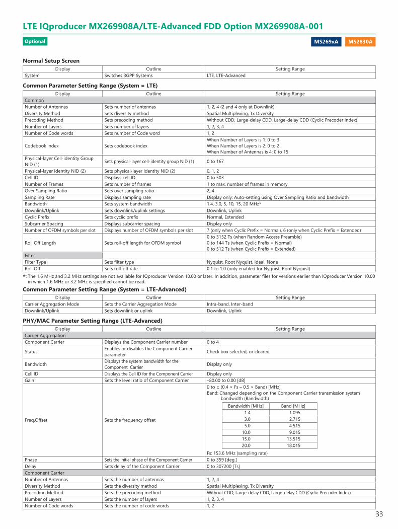
Normal Setup ScreenDisplay Outline Setting Range
System Switches 3GPP Systems LTE, LTE-Advanced
Common Parameter Setting Range (System = LTE)Display Outline Setting Range
CommonNumber of Antennas Sets number of antennas 1, 2, 4 (2 and 4 only at Downlink)Diversity Method Sets diversity method Spatial Multiplexing, Tx DiversityPrecoding Method Sets precoding method Without CDD, Large-delay CDD, Large-delay CDD (Cyclic Precoder Index)Number of Layers Sets number of layers 1, 2, 3, 4Number of Code words Sets number of Code word 1, 2
Codebook index Sets codebook indexWhen Number of Layers is 1: 0 to 3When Number of Layers is 2: 0 to 2When Number of Antennas is 4: 0 to 15
Physical-layer Cell-identity Group NID (1) Sets physical-layer cell-identity group NID (1) 0 to 167
Physical-layer Identity NID (2) Sets physical-layer identity NID (2) 0, 1, 2Cell ID Displays cell ID 0 to 503Number of Frames Sets number of frames 1 to max. number of frames in memoryOver Sampling Ratio Sets over sampling ratio 2, 4Sampling Rate Displays sampling rate Display only: Auto-setting using Over Sampling Ratio and bandwidthBandwidth Sets system bandwidth 1.4, 3.0, 5, 10, 15, 20 MHz*Downlink/Uplink Sets downlink/uplink settings Downlink, UplinkCyclic Prefix Sets cyclic prefix Normal, ExtendedSubcarrier Spacing Displays subcarrier spacing Display onlyNumber of OFDM symbols per slot Displays number of OFDM symbols per slot 7 (only when Cyclic Prefix = Normal), 6 (only when Cyclic Prefix = Extended)
Roll Off Length Sets roll-off length for OFDM symbol0 to 3152 Ts (when Random Access Preamble)0 to 144 Ts (when Cyclic Prefix = Normal)0 to 512 Ts (when Cyclic Prefix = Extended)
FilterFilter Type Sets filter type Nyquist, Root Nyquist, Ideal, NoneRoll Off Sets roll-off rate 0.1 to 1.0 (only enabled for Nyquist, Root Nyquist)
*: The 1.6 MHz and 3.2 MHz settings are not available for IQproducer Version 10.00 or later. In addition, parameter files for versions earlier than IQproducer Version 10.00 in which 1.6 MHz or 3.2 MHz is specified cannot be read.
Common Parameter Setting Range (System = LTE-Advanced)Display Outline Setting Range
Carrier Aggregation Mode Sets the Carrier Aggregation Mode Intra-band, Inter-bandDownlink/Uplink Sets downlink or uplink Downlink, Uplink
PHY/MAC Parameter Setting Range (LTE-Advanced)Display Outline Setting Range
Carrier AggregationComponent Carrier Displays the Component Carrier number 0 to 4
Status Enables or disables the Component Carrier parameter Check box selected, or cleared
Bandwidth Displays the system bandwidth for the Component Carrier Display only
Cell ID Displays the Cell ID for the Component Carrier Display onlyGain Sets the level ratio of Component Carrier –80.00 to 0.00 [dB]
Freq.Offset Sets the frequency offset
0 to ± (0.4 × Fs – 0.5 × Band) [MHz]Band: Changed depending on the Component Carrier transmission system
bandwidth (Bandwidth)Bandwidth [MHz] Band [MHz]
1.4 1.095 3.0 2.715 5.0 4.515 10.0 9.015 15.0 13.515 20.0 18.015
Fs: 153.6 MHz (sampling rate)Phase Sets the initial phase of the Component Carrier 0 to 359 [deg.]Delay Sets delay of the Component Carrier 0 to 307200 [Ts]Component CarrierNumber of Antennas Sets the number of antennas 1, 2, 4Diversity Method Sets the diversity method Spatial Multiplexing, Tx DiversityPrecoding Method Sets the precoding method Without CDD, Large-delay CDD, Large-delay CDD (Cyclic Precoder Index)Number of Layers Sets the number of layers 1, 2, 3, 4Number of Code words Sets the number of code words 1, 2
LTE IQproducer MX269908A/LTE-Advanced FDD Option MX269908A-001Optional
33

MS269xA MS2830A
Display Outline Setting Range
Codebook index Sets the codebook index
When Number of Antennas is 2, the setting range varies according to Number of Layers as followsWhen Number of Layers is 1: 0 to 3When Number of Layers is 2: 0 to 2When Number of Layers is 4: 0 to 15
NID (1) Sets the NID (1) 0 to 167NID (2) Sets the NID (2) 0, 1, 2Cell ID Sets the Cell ID 0 to 503
Number of Frames Sets the number of frames to be generated 1 to the maximum number of frames that can be stored in the main unit's waveform memory
Over Sampling Ratio Sets the oversampling ratio 1, 2, 4
Sampling Rate Displays the sampling rate Display only: automatically set according to the Oversampling Ratio and Bandwidth values
Bandwidth Sets the system bandwidth 1.4, 3, 5, 10, 15, 20 MHzCyclic Prefix Sets the cyclic prefix Normal, ExtendedSubcarrier Spacing Displays the subcarrier spacing (interval) Display onlyNumber of OFDM symbols per slot Sets the number of OFDM symbols per slot Display only
Roll Off Length Sets the length of the ramp time applied to the OFDM symbol
0 to 3152 Ts (Random Access Preamble)0 to 144 Ts (Cyclic prefix = Normal)0 to 512 Ts (Cyclic prefix = Extended)
FilterFilter Type Sets the filter type Nyquist, Root Nyquist, Ideal, NoneRoll Off Sets the roll-off factor 0.1 to 1.0
PHY/MAC Parameter (Downlink) Setting RangeDisplay Outline Setting Range
DownlinkPHICH Sets ON/OFF for PHICH ON, OFFPHICH duration Sets the PHICH area Normal, Extended
Ng Sets the parameter (Ng) for determining the PHICH arrangement 1/6, 1/2, 1, 2
Reference SignalReference Signal Sequence Sets data used as reference signal sequence Gold Sequence, PN9fix, PN15fix, 16 bit repeat, User FileReference Signal Sequence Repeat Data
Sets 16 bit repeat data installed in reference signal sequence
0000 to FFFF(only when reference signal sequence = 16 bit repeat)
Reference Signal Sequence User File Sets user file installed in reference signal sequence Select any file (only when reference signal sequence = User File)Frequency Shift Value Displays frequency shift 0, 1, 2, 3, 4, 5Power Boosting Sets power boosting –20.000 to +20.000 dBPBCHData Status Enables/disables PBCH parameter Disable, EnableData Type Sets data type PN9fix, PN15fix, 16 bit repeat, User File, BCHData Type Repeat Data Sets 16 bit repeat data 0000 to FFFF (only when Data Type = 16 bit repeat)Data Type User File Sets user file Select any file (only when Data Type = User File)Power Boosting Sets power boosting –20.000 to +20.000 dBBCHData Type Sets data type PN9fix, PN15fix, 16 bit repeat, User File, BCCHData Type Repeat Data Sets 16 bit repeat data installed in BCH 0000 to FFFF (only when Data Type = 16 bit repeat)Data Type User File Sets user file to install in BCH Select any file (only when Data Type = User File)
Transport Block Size Sets number of bits required for BCH When Cyclic Prefix = Normal, Max. 1920When Cyclic Prefix = Extended, Max. 1728
DL Bandwidth Displays data mapped to BCCH n6, n15, n25, n50, n75, n100PHICH duration Displays the PHICH duration mapped to BCCH Normal, ExtendedNg Displays the Ng value mapped to BCCH 1/6, 1/2, 1, 2SFN Offset Sets the initial SFN value mapped to BCCH 0 to 1023Synchronization SignalsPrimary Synchronization Signal
Data Status Enables/disables primary synchronization signal parameter Disable, Enable
Data Type Sets data type Zadoff-Chu Sequence, User File
Data Type User File Sets user file to install in primary synchronization signal Select any file (only when Data Type = User File)
Zadoff-Chu Sequence index u Displays Zadoff-Chu Sequence index u 25, 29, 34Power Boosting Sets power boosting –20.000 to +20.000 dBSecondary Synchronization Signal
Data Status Enables/disables secondary synchronization signal parameter Disable, Enable
Data Type Sets data type Concatenated sequence, PN9fix, PN15fix, 16 bit repeat, User FileData Type Repeat Data Sets 16 bit repeat data 0000 to FFFF (only when Data Type = 16 bit repeat)Data Type User File Sets user file Select any file (only when Data Type = User File)Power Boosting Sets power boosting –20.000 to +20.000 dB
Optional
LTE IQproducer MX269908A/LTE-Advanced FDD Option MX269908A-001
34
MS269xA MS2830A
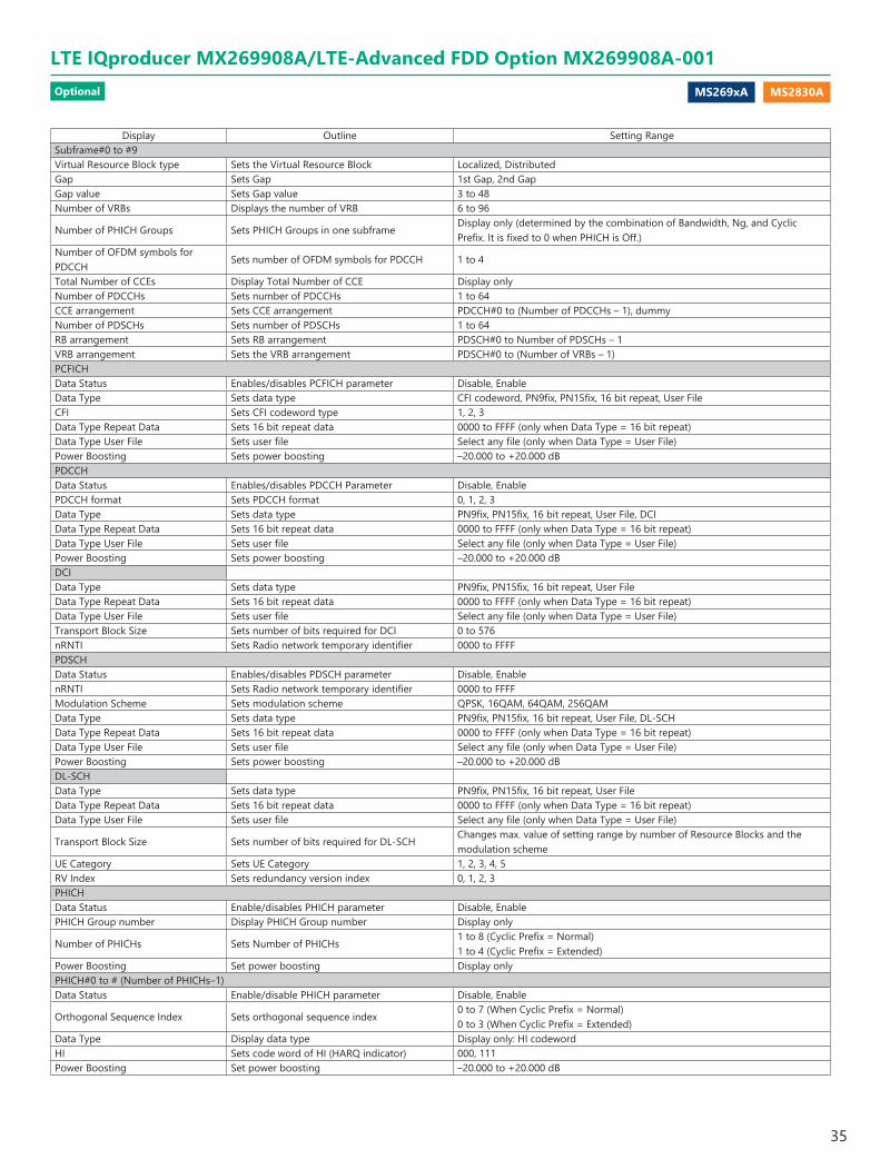
Display Outline Setting RangeSubframe#0 to #9Virtual Resource Block type Sets the Virtual Resource Block Localized, DistributedGap Sets Gap 1st Gap, 2nd GapGap value Sets Gap value 3 to 48Number of VRBs Displays the number of VRB 6 to 96
Number of PHICH Groups Sets PHICH Groups in one subframeDisplay only (determined by the combination of Bandwidth, Ng, and Cyclic Prefix. It is fixed to 0 when PHICH is Off.)
Number of OFDM symbols for PDCCH
Sets number of OFDM symbols for PDCCH 1 to 4
Total Number of CCEs Display Total Number of CCE Display onlyNumber of PDCCHs Sets number of PDCCHs 1 to 64CCE arrangement Sets CCE arrangement PDCCH#0 to (Number of PDCCHs – 1), dummyNumber of PDSCHs Sets number of PDSCHs 1 to 64RB arrangement Sets RB arrangement PDSCH#0 to Number of PDSCHs – 1VRB arrangement Sets the VRB arrangement PDSCH#0 to (Number of VRBs – 1)PCFICHData Status Enables/disables PCFICH parameter Disable, EnableData Type Sets data type CFI codeword, PN9fix, PN15fix, 16 bit repeat, User FileCFI Sets CFI codeword type 1, 2, 3Data Type Repeat Data Sets 16 bit repeat data 0000 to FFFF (only when Data Type = 16 bit repeat)Data Type User File Sets user file Select any file (only when Data Type = User File)Power Boosting Sets power boosting –20.000 to +20.000 dBPDCCHData Status Enables/disables PDCCH Parameter Disable, EnablePDCCH format Sets PDCCH format 0, 1, 2, 3Data Type Sets data type PN9fix, PN15fix, 16 bit repeat, User File, DCIData Type Repeat Data Sets 16 bit repeat data 0000 to FFFF (only when Data Type = 16 bit repeat)Data Type User File Sets user file Select any file (only when Data Type = User File)Power Boosting Sets power boosting –20.000 to +20.000 dBDCIData Type Sets data type PN9fix, PN15fix, 16 bit repeat, User FileData Type Repeat Data Sets 16 bit repeat data 0000 to FFFF (only when Data Type = 16 bit repeat)Data Type User File Sets user file Select any file (only when Data Type = User File)Transport Block Size Sets number of bits required for DCI 0 to 576nRNTI Sets Radio network temporary identifier 0000 to FFFFPDSCHData Status Enables/disables PDSCH parameter Disable, EnablenRNTI Sets Radio network temporary identifier 0000 to FFFFModulation Scheme Sets modulation scheme QPSK, 16QAM, 64QAM, 256QAMData Type Sets data type PN9fix, PN15fix, 16 bit repeat, User File, DL-SCHData Type Repeat Data Sets 16 bit repeat data 0000 to FFFF (only when Data Type = 16 bit repeat)Data Type User File Sets user file Select any file (only when Data Type = User File)Power Boosting Sets power boosting –20.000 to +20.000 dBDL-SCHData Type Sets data type PN9fix, PN15fix, 16 bit repeat, User FileData Type Repeat Data Sets 16 bit repeat data 0000 to FFFF (only when Data Type = 16 bit repeat)Data Type User File Sets user file Select any file (only when Data Type = User File)
Transport Block Size Sets number of bits required for DL-SCHChanges max. value of setting range by number of Resource Blocks and the modulation scheme
UE Category Sets UE Category 1, 2, 3, 4, 5RV Index Sets redundancy version index 0, 1, 2, 3PHICHData Status Enable/disables PHICH parameter Disable, EnablePHICH Group number Display PHICH Group number Display only
Number of PHICHs Sets Number of PHICHs1 to 8 (Cyclic Prefix = Normal)1 to 4 (Cyclic Prefix = Extended)
Power Boosting Set power boosting Display onlyPHICH#0 to # (Number of PHICHs–1)Data Status Enable/disable PHICH parameter Disable, Enable
Orthogonal Sequence Index Sets orthogonal sequence index0 to 7 (When Cyclic Prefix = Normal)0 to 3 (When Cyclic Prefix = Extended)
Data Type Display data type Display only: HI codewordHI Sets code word of HI (HARQ indicator) 000, 111Power Boosting Set power boosting –20.000 to +20.000 dB
LTE IQproducer MX269908A/LTE-Advanced FDD Option MX269908A-001Optional
35

MS269xA MS2830A
PHY/MAC Parameter (Uplink) Setting RangeDisplay Outline Setting Range
UplinkData Transmission/Random Access Preamble
Selects Data Transmission or Random Access Preamble Data Transmission/Random Access Preamble
DMRS Parameters Sets the calculation method of Demodulation RS parameter. Auto, Manual
PUCCH Parametersdelta PUCCH shift Sets delta PUCCH shift 1, 2, 3
N_CS(1)Sets the value of N_CS(1), which is the number of cyclic shifts used in the PUCCH formats 1, 1a, and 1b
0 to 7
N_RB(2)Sets the value of N_RB(2), which is the number of resource blocks used in the PUCCH formats 2, 2a, and 2b
0 to 63
Sounding RS ParametersSRS Sets SRS ON/OFF ON, OFFSRS Subframe Configuration Sets the SRS Subframe Configuration 0 to 14Subframe#0 to #9 (Data Transmission)Number of PUCCHs Sets number of PUCCH 0, 1, 2, 3, 4, 5, 6, 7, 8Number of PUSCHs Sets number of PUSCH 0, 1, 2, 3, 4, 5, 6, 7, 8PUCCH#0 to #7Data Status Enables/disables PUCCH parameter Disable, Enable
n(1)_PUCCH Sets the resource number for PUCCH 1, 1a, and 1b 0 to 764
n(2)_PUCCH Sets the resource number for PUCCH 2, 2a, and 2b 0 to 764
nRNTI Sets Radio network temporary identifier 0000 to FFFFPUCCH format Sets PUCCH format 1, 1a, 1b, 2, 2a, 2bData Type Sets data type PN9fix, PN15fix, 16 bit repeat, User File, UCIData Type Repeat Data Sets 16 bit repeat data 0000 to FFFF (only when Data Type = 16 bit repeat)Data Type User File Sets user file Select any file (only when Data Type = User File)Group Hopping Enables or disables group hopping Disable, EnableBase Sequence Group Number u Sets base sequence group number 0 to 29Base Sequence Number v Displays base sequence number 0 fixedPower Boosting Sets power boosting –20.000 to +20.000 dBUCI
Transport Block Size Sets transport block size of UCI
1 (When PUCCH format = 1a)2 (When PUCCH format = 1b)1 to 13 (When PUCCH format = 2) 2 to 14 (When PUCCH format = 2a)3 to 15 (When PUCCH format = 2b)
Data Type Sets data type PN9fix, PN15fix, 16 bit repeat, User FileData Type Repeat Data Sets 16 bit repeat data 0000 to FFFF (only when Data Type = 16 bit repeat)Data Type User File Sets user file Select any file (only when Data Type = User File)Demodulation RS for PUCCH Data Type Sets data type Base Sequence, User FileData Type User File Sets user file Select any file (only when Data Type = User File)Group Hopping Enable/disable Group Hopping parameter Disable, EnableBase Sequence Group Number u Sets base sequence group number 0 to 29Base Sequence Number v Displays base sequence group number 0 fixedPUSCH#0 to #7Data Status Enables/disables PUSCH parameter Disable, EnablenRNTI Sets Radio network temporary identifier 0000 to FFFFModulation Scheme Sets modulation system QPSK, 16QAM, 64QAMData Type Sets data type PN9fix, PN15fix, 16 bit repeat, User File, UL-SCHData Type Repeat Data Sets 16 bit repeat data 0000 to FFFF (only when Data Type = 16 bit repeat)Data Type User File Sets user file Select any file (only when Data Type = User File)
Resource allocation type Sets the Resource allocation type type0, type1 When type1 is selected, Start Number of RB and Number of RBs cannot be set
Start Number of RB Start position of RB
When Bandwidth is 1.4 MHz: 0 to 5When Bandwidth is 3 MHz: 0 to 14When Bandwidth is 5 MHz: 0 to 24When Bandwidth is 10 MHz: 0 to 49When Bandwidth is 15 MHz: 0 to 74When Bandwidth is 20 MHz: 0 to 99
Number of RBs Total number of RB
When Bandwidth is 1.4 MHz: 1 to 6When Bandwidth is 3 MHz: 1 to 15When Bandwidth is 5 MHz: 1 to 25When Bandwidth is 10 MHz: 1 to 50When Bandwidth is 15 MHz: 1 to 75When Bandwidth is 20 MHz: 1 to 100
Optional
LTE IQproducer MX269908A/LTE-Advanced FDD Option MX269908A-001
36
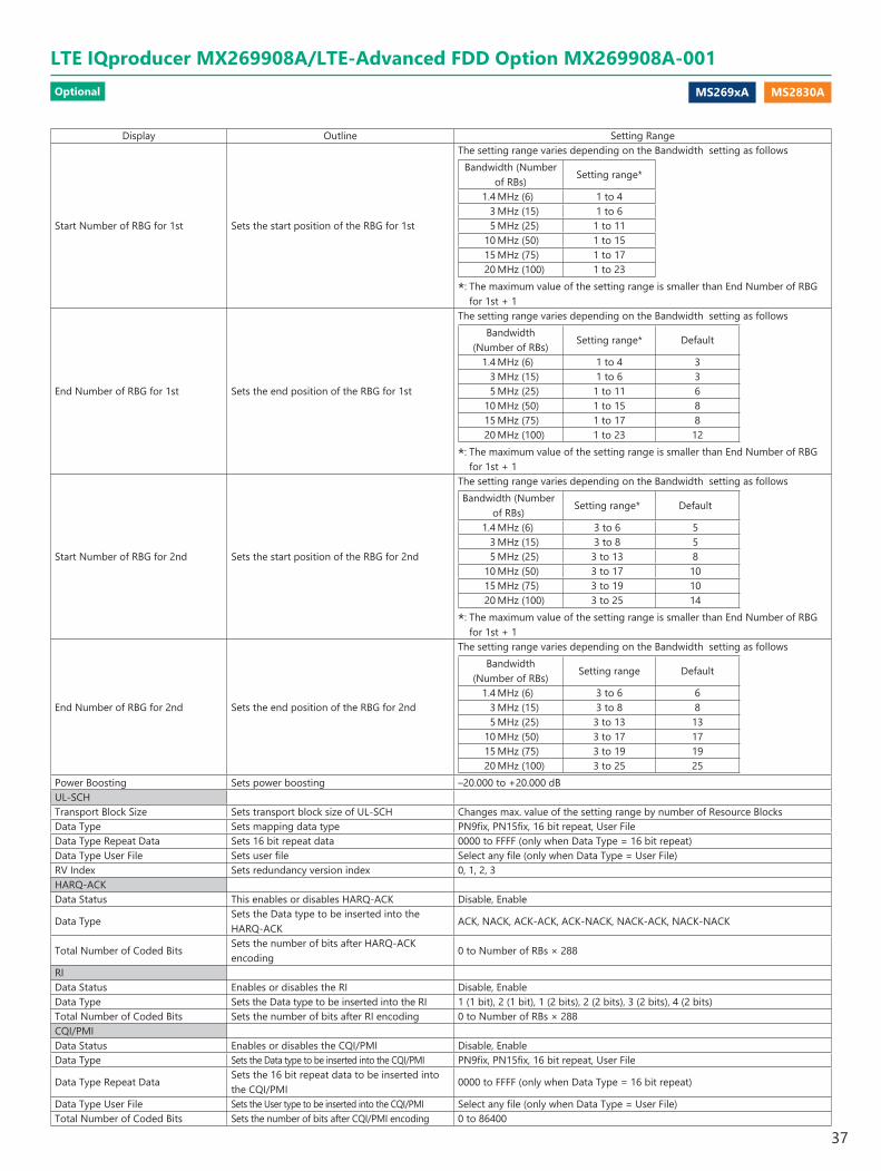
MS269xA MS2830A
Display Outline Setting Range
Start Number of RBG for 1st Sets the start position of the RBG for 1st
The setting range varies depending on the Bandwidth setting as followsBandwidth (Number
of RBs)Setting range*
1.4 MHz (6) 1 to 4 3 MHz (15) 1 to 6 5 MHz (25) 1 to 11 10 MHz (50) 1 to 15 15 MHz (75) 1 to 17 20 MHz (100) 1 to 23
*: The maximum value of the setting range is smaller than End Number of RBG for 1st + 1
End Number of RBG for 1st Sets the end position of the RBG for 1st
The setting range varies depending on the Bandwidth setting as followsBandwidth
(Number of RBs)Setting range* Default
1.4 MHz (6) 1 to 4 3 3 MHz (15) 1 to 6 3 5 MHz (25) 1 to 11 6 10 MHz (50) 1 to 15 8 15 MHz (75) 1 to 17 8 20 MHz (100) 1 to 23 12
*: The maximum value of the setting range is smaller than End Number of RBG for 1st + 1
Start Number of RBG for 2nd Sets the start position of the RBG for 2nd
The setting range varies depending on the Bandwidth setting as followsBandwidth (Number
of RBs)Setting range* Default
1.4 MHz (6) 3 to 6 5 3 MHz (15) 3 to 8 5 5 MHz (25) 3 to 13 8 10 MHz (50) 3 to 17 10 15 MHz (75) 3 to 19 10 20 MHz (100) 3 to 25 14
*: The maximum value of the setting range is smaller than End Number of RBG for 1st + 1
End Number of RBG for 2nd Sets the end position of the RBG for 2nd
The setting range varies depending on the Bandwidth setting as followsBandwidth
(Number of RBs)Setting range Default
1.4 MHz (6) 3 to 6 6 3 MHz (15) 3 to 8 8 5 MHz (25) 3 to 13 13 10 MHz (50) 3 to 17 17 15 MHz (75) 3 to 19 19 20 MHz (100) 3 to 25 25
Power Boosting Sets power boosting –20.000 to +20.000 dBUL-SCHTransport Block Size Sets transport block size of UL-SCH Changes max. value of the setting range by number of Resource BlocksData Type Sets mapping data type PN9fix, PN15fix, 16 bit repeat, User FileData Type Repeat Data Sets 16 bit repeat data 0000 to FFFF (only when Data Type = 16 bit repeat)Data Type User File Sets user file Select any file (only when Data Type = User File)RV Index Sets redundancy version index 0, 1, 2, 3HARQ-ACKData Status This enables or disables HARQ-ACK Disable, Enable
Data TypeSets the Data type to be inserted into the HARQ-ACK
ACK, NACK, ACK-ACK, ACK-NACK, NACK-ACK, NACK-NACK
Total Number of Coded BitsSets the number of bits after HARQ-ACK encoding
0 to Number of RBs × 288
RIData Status Enables or disables the RI Disable, EnableData Type Sets the Data type to be inserted into the RI 1 (1 bit), 2 (1 bit), 1 (2 bits), 2 (2 bits), 3 (2 bits), 4 (2 bits)Total Number of Coded Bits Sets the number of bits after RI encoding 0 to Number of RBs × 288CQI/PMIData Status Enables or disables the CQI/PMI Disable, EnableData Type Sets the Data type to be inserted into the CQI/PMI PN9fix, PN15fix, 16 bit repeat, User File
Data Type Repeat DataSets the 16 bit repeat data to be inserted into the CQI/PMI
0000 to FFFF (only when Data Type = 16 bit repeat)
Data Type User File Sets the User type to be inserted into the CQI/PMI Select any file (only when Data Type = User File)Total Number of Coded Bits Sets the number of bits after CQI/PMI encoding 0 to 86400
LTE IQproducer MX269908A/LTE-Advanced FDD Option MX269908A-001Optional
37
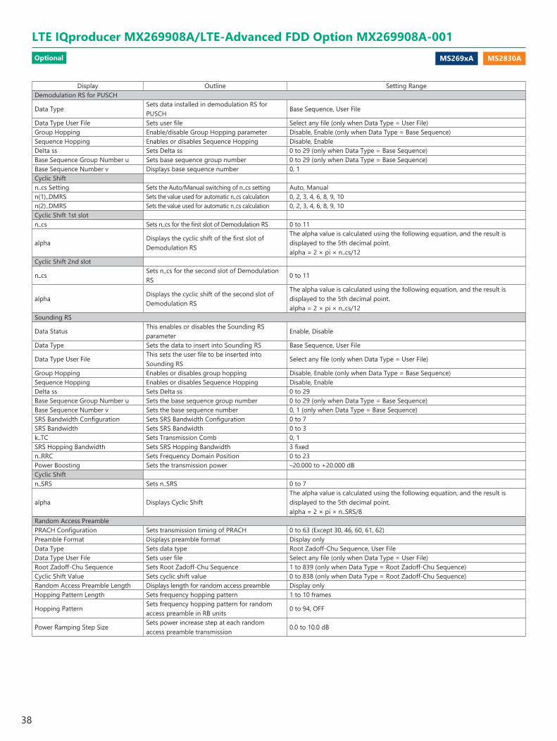
MS269xA MS2830A
Display Outline Setting RangeDemodulation RS for PUSCH
Data TypeSets data installed in demodulation RS for PUSCH
Base Sequence, User File
Data Type User File Sets user file Select any file (only when Data Type = User File)Group Hopping Enable/disable Group Hopping parameter Disable, Enable (only when Data Type = Base Sequence)Sequence Hopping Enables or disables Sequence Hopping Disable, EnableDelta ss Sets Delta ss 0 to 29 (only when Data Type = Base Sequence)Base Sequence Group Number u Sets base sequence group number 0 to 29 (only when Data Type = Base Sequence)Base Sequence Number v Displays base sequence number 0, 1Cyclic Shiftn_cs Setting Sets the Auto/Manual switching of n_cs setting Auto, Manualn(1)_DMRS Sets the value used for automatic n_cs calculation 0, 2, 3, 4, 6, 8, 9, 10n(2)_DMRS Sets the value used for automatic n_cs calculation 0, 2, 3, 4, 6, 8, 9, 10Cyclic Shift 1st slotn_cs Sets n_cs for the first slot of Demodulation RS 0 to 11
alphaDisplays the cyclic shift of the first slot of Demodulation RS
The alpha value is calculated using the following equation, and the result is displayed to the 5th decimal point.alpha = 2 × pi × n_cs/12
Cyclic Shift 2nd slot
n_csSets n_cs for the second slot of Demodulation RS
0 to 11
alphaDisplays the cyclic shift of the second slot of Demodulation RS
The alpha value is calculated using the following equation, and the result is displayed to the 5th decimal point.alpha = 2 × pi × n_cs/12
Sounding RS
Data StatusThis enables or disables the Sounding RS parameter
Enable, Disable
Data Type Sets the data to insert into Sounding RS Base Sequence, User File
Data Type User FileThis sets the user file to be inserted into Sounding RS
Select any file (only when Data Type = User File)
Group Hopping Enables or disables group hopping Disable, Enable (only when Data Type = Base Sequence)Sequence Hopping Enables or disables Sequence Hopping Disable, EnableDelta ss Sets Delta ss 0 to 29Base Sequence Group Number u Sets the base sequence group number 0 to 29 (only when Data Type = Base Sequence)Base Sequence Number v Sets the base sequence number 0, 1 (only when Data Type = Base Sequence)SRS Bandwidth Configuration Sets SRS Bandwidth Configuration 0 to 7SRS Bandwidth Sets SRS Bandwidth 0 to 3k_TC Sets Transmission Comb 0, 1SRS Hopping Bandwidth Sets SRS Hopping Bandwidth 3 fixedn_RRC Sets Frequency Domain Position 0 to 23Power Boosting Sets the transmission power –20.000 to +20.000 dBCyclic Shiftn_SRS Sets n_SRS 0 to 7
alpha Displays Cyclic ShiftThe alpha value is calculated using the following equation, and the result is displayed to the 5th decimal point.alpha = 2 × pi × n_SRS/8
Random Access PreamblePRACH Configuration Sets transmission timing of PRACH 0 to 63 (Except 30, 46, 60, 61, 62)Preamble Format Displays preamble format Display onlyData Type Sets data type Root Zadoff-Chu Sequence, User FileData Type User File Sets user file Select any file (only when Data Type = User File)Root Zadoff-Chu Sequence Sets Root Zadoff-Chu Sequence 1 to 839 (only when Data Type = Root Zadoff-Chu Sequence)Cyclic Shift Value Sets cyclic shift value 0 to 838 (only when Data Type = Root Zadoff-Chu Sequence)Random Access Preamble Length Displays length for random access preamble Display onlyHopping Pattern Length Sets frequency hopping pattern 1 to 10 frames
Hopping PatternSets frequency hopping pattern for random access preamble in RB units
0 to 94, OFF
Power Ramping Step SizeSets power increase step at each random access preamble transmission
0.0 to 10.0 dB
Optional
LTE IQproducer MX269908A/LTE-Advanced FDD Option MX269908A-001
38
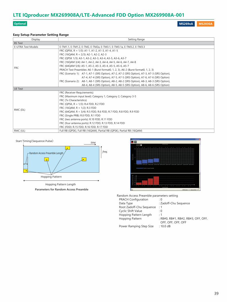
MS269xA MS2830A
freq.
time
Hopping Pattern Length
Hopping Pattern
Start Timing(Sequence Pulse)
Random Access Preamble Length
Parameters for Random Access Preamble
Random Access Preamble parameters settingPRACH Configuration : 0Data Type : Zadoff-Chu SequenceRoot Zadoff-Chu Sequence : 1Cyclic Shift Value : 0Hopping Pattern Length : 1Hopping Pattern : RB#0, RB#1, RB#2, RB#3, OFF, OFF,
OFF, OFF, OFF, OFFPower Ramping Step Size : 10.0 dB
Easy Setup Parameter Setting RangeDisplay Setting Range
BS TestE-UTRA Test Models E-TM1.1, E-TM1.2, E-TM2, E-TM2a, E-TM3.1, E-TM3.1a, E-TM3.2, E-TM3.3
FRC
FRC (QPSK, R = 1/3): A1-1, A1-2, A1-3, A1-4, A1-5FRC (16QAM, R = 2/3): A2-1, A2-2, A2-3FRC (QPSK 1/3): A3-1, A3-2, A3-3, A3-4, A3-5, A3-6, A3-7FRC (16QAM 3/4): A4-1, A4-2, A4-3, A4-4, A4-5, A4-6, A4-7, A4-8FRC (64QAM 5/6): A5-1, A5-2, A5-3, A5-4, A5-5, A5-6, A5-7PRACH Test Preambles: A6-1 (Burst format0, 1, 2, 3), A6-2 (Burst format0, 1, 2, 3)FRC (Scenario 1): A7-1, A7-1 (SRS Option), A7-2, A7-2 (SRS Option), A7-3, A7-3 (SRS Option),
A7-4, A7-4 (SRS Option), A7-5, A7-5 (SRS Option), A7-6, A7-6 (SRS Option)FRC (Scenario 2): A8-1, A8-1 (SRS Option), A8-2, A8-2 (SRS Option), A8-3, A8-3 (SRS Option),
A8-4, A8-4 (SRS Option), A8-5, A8-5 (SRS Option), A8-6, A8-6 (SRS Option)UE Test
RMC (DL)
FRC (Receiver Requirements)FRC (Maximum input level): Category 1, Category 2, Category 3-5FRC (Tx Characteristics)FRC (QPSK, R = 1/3): R.4 FDD, R.2 FDDFRC (16QAM, R = 1/2): R.3 FDDFRC (64QAM, R = 3/4): R.5 FDD, R.6 FDD, R.7 FDD, R.8 FDD, R.9 FDDFRC (Single PRB): R.0 FDD, R.1 FDDFRC (two antenna ports): R.10 FDD, R.11 FDDFRC (four antenna ports): R.12 FDD, R.13 FDD, R.14 FDDFRC (FDD): R.15 FDD, R.16 FDD, R.17 FDD
RMC (UL) Full RB (QPSK), Full RB (16QAM), Partial RB (QPSK), Partial RB (16QAM)
LTE IQproducer MX269908A/LTE-Advanced FDD Option MX269908A-001Optional
39
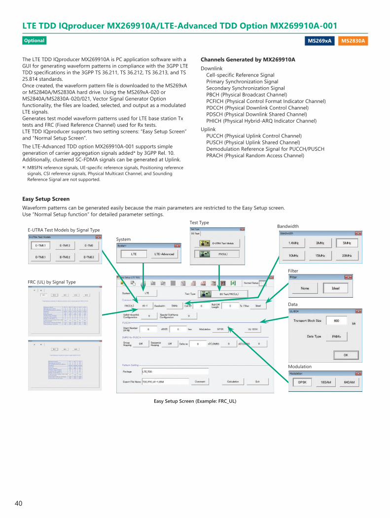
MS269xA MS2830A
The LTE TDD IQproducer MX269910A is PC application software with a GUI for generating waveform patterns in compliance with the 3GPP LTE TDD specifications in the 3GPP TS 36.211, TS 36.212, TS 36.213, and TS 25.814 standards. Once created, the waveform pattern file is downloaded to the MS269xA or MS2840A/MS2830A hard drive. Using the MS269xA-020 or MS2840A/MS2830A-020/021, Vector Signal Generator Option functionality, the files are loaded, selected, and output as a modulated LTE signals.Generates test model waveform patterns used for LTE base station Tx tests and FRC (Fixed Reference Channel) used for Rx tests. LTE TDD IQproducer supports two setting screens: “Easy Setup Screen” and “Normal Setup Screen”.The LTE-Advanced TDD option MX269910A-001 supports simple generation of carrier aggregation signals added* by 3GPP Rel. 10.Additionally, clustered SC-FDMA signals can be generated at Uplink.
*: MBSFN reference signals, UE-specific reference signals, Positioning reference signals, CSI reference signals, Physical Multicast Channel, and Sounding Reference Signal are not supported.
Channels Generated by MX269910ADownlink
Cell-specific Reference SignalPrimary Synchronization SignalSecondary Synchronization SignalPBCH (Physical Broadcast Channel)PCFICH (Physical Control Format Indicator Channel)PDCCH (Physical Downlink Control Channel)PDSCH (Physical Downlink Shared Channel)PHICH (Physical Hybrid-ARQ Indicator Channel)
UplinkPUCCH (Physical Uplink Control Channel)PUSCH (Physical Uplink Shared Channel)Demodulation Reference Signal for PUCCH/PUSCHPRACH (Physical Random Access Channel)
Easy Setup ScreenWaveform patterns can be generated easily because the main parameters are restricted to the Easy Setup screen.Use “Normal Setup function” for detailed parameter settings.
Modulation
Filter
FRC (UL) by Signal Type
E-UTRA Test Models by Signal TypeBandwidth
Data
Test Type
Easy Setup Screen (Example: FRC_UL)
System
LTE TDD IQproducer MX269910A/LTE-Advanced TDD Option MX269910A-001Optional
40

MS269xA MS2830A
BS Test/E-UTRA Test Models
Easy Setup Menu3GPP-defined test conditions can be selected from the Easy Setup menu tree to set values for the Normal Setup screen parameters.
BS Test/FRC
Visual Check at Frame Structure Screen
Displays Frame Structure screen for confirming channel allocation status and power of each OFDM Symbol
Normal Setup ScreenDetailed parameters are set at the Normal Setup screen to generate waveform patterns.
The Frame Structure Screen shows the resource element allocation graphically with each channel color-coded.Y-axis: Frequency (Resource Block units)X-axis: Time (OFDM Symbol units)In the Full Scale display, one frame (Subframe#0 to 9) is displayed. The zoom can be done by selecting the area with the cursor. When the Full Scale button is pushed, one frame is displayed. Moreover, when the cursor is set in each channel, and "Properties" is selected by right-clicking, information on the setting of the channel etc. is displayed.
The Power Graph shows the power relative levels of OFDM Symbols with maximum power of 0 dB.Y-axis: OFDM Symbol PowerX-axis: Time (OFDM Symbol units)
Frame Structure Screen (LTE)
PHY/MAC parameter items are displayed as a tree hierarchy.
Sets Common Parameters
Displays errors, etc.
Sets parameters for items selected in tree on left
LTE TDD IQproducer Setting Screen/Normal Setup Screen
LTE TDD IQproducer MX269910A/LTE-Advanced TDD Option MX269910A-001Optional
41
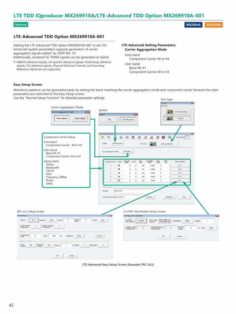
MS269xA MS2830A
LTE-Advanced TDD Option MX269910A-001
Adding the LTE-Advanced TDD option MX269910A-001 to set LTE-Advanced system parameters supports generation of carrier aggregation signals added* by 3GPP Rel. 10.Additionally, clustered SC-FDMA signals can be generated at Uplink.
*: MBSFN reference signals, UE-specific reference signals, Positioning reference signals, CSI reference signals, Physical Multicast Channel, and Sounding Reference Signal are not supported.
Easy Setup ScreenWaveform patterns can be generated easily by setting the band matching the carrier aggregation mode and component carrier because the main parameters are restricted to the Easy Setup screen.Use the “Normal Setup Function” for detailed parameter settings.
LTE-Advanced Setting Parameters Carrier Aggregation ModeIntra-band
Component Carrier #0 to #4Inter-band
Band #0, #1Component Carrier #0 to #4
LTE-Advanced Easy Setup Screen (Example: FRC (UL))
FRC (UL) Setup Screen E-UTRA Test Models Setup Screen
Carrier Aggregation Mode
Test Type
System
Component Carrier SetupIntra-band
Component Carrier: #0 to #4Inter-band
Band #0, #1Component Carrier #0 to #4
[Setup Item] StatusBandwidthCell IDGainFrequency OffsetPhaseDelay
LTE TDD IQproducer MX269910A/LTE-Advanced TDD Option MX269910A-001Optional
42
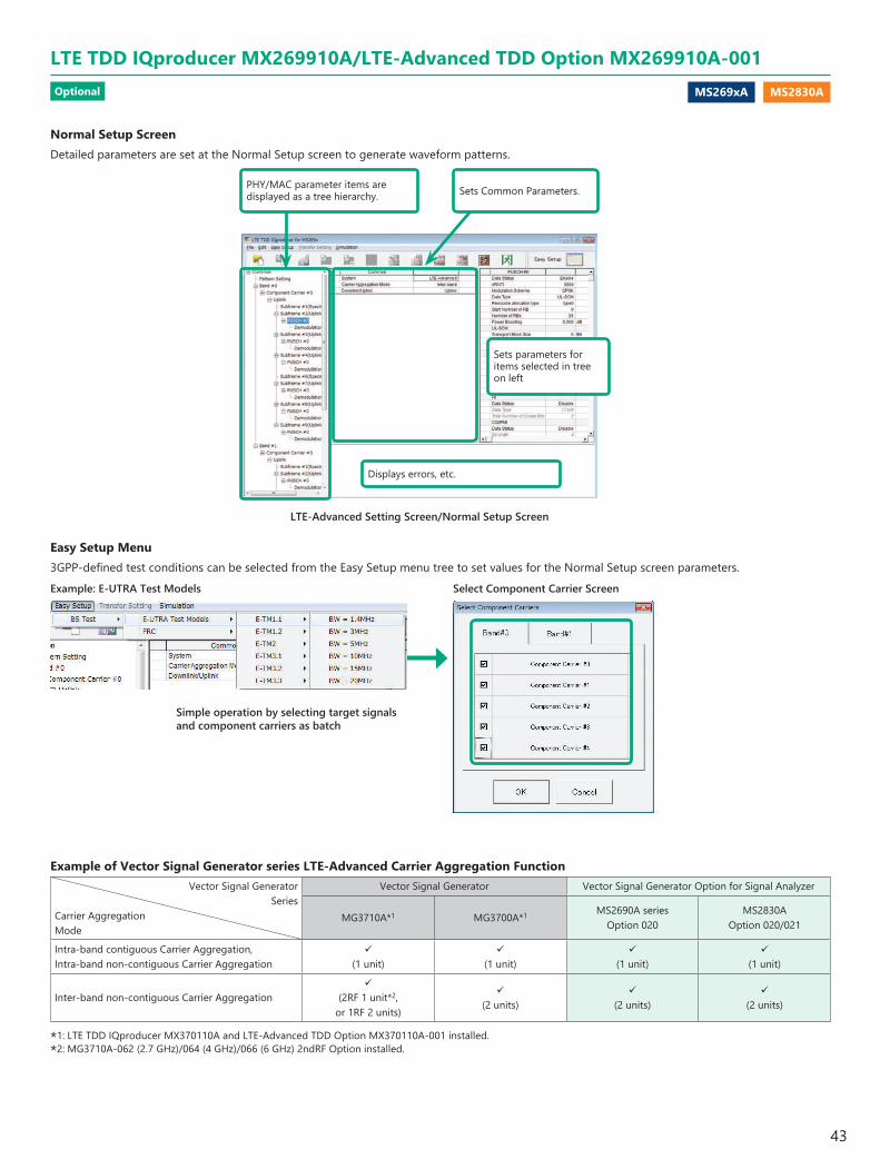
MS269xA MS2830A
PHY/MAC parameter items are displayed as a tree hierarchy. Sets Common Parameters.
Displays errors, etc.
Sets parameters for items selected in tree on left
LTE-Advanced Setting Screen/Normal Setup Screen
Simple operation by selecting target signals and component carriers as batch
Example of Vector Signal Generator series LTE-Advanced Carrier Aggregation Function Vector Signal Generator
Series Carrier AggregationMode
Vector Signal Generator Vector Signal Generator Option for Signal Analyzer
MG3710A*1 MG3700A*1 MS2690A seriesOption 020
MS2830AOption 020/021
Intra-band contiguous Carrier Aggregation, Intra-band non-contiguous Carrier Aggregation
(1 unit)
(1 unit)
(1 unit)
(1 unit)
Inter-band non-contiguous Carrier Aggregation
(2RF 1 unit*2, or 1RF 2 units)
(2 units)
(2 units)
(2 units)
*1: LTE TDD IQproducer MX370110A and LTE-Advanced TDD Option MX370110A-001 installed.*2: MG3710A-062 (2.7 GHz)/064 (4 GHz)/066 (6 GHz) 2ndRF Option installed.
Select Component Carrier ScreenExample: E-UTRA Test Models
Normal Setup ScreenDetailed parameters are set at the Normal Setup screen to generate waveform patterns.
Easy Setup Menu3GPP-defined test conditions can be selected from the Easy Setup menu tree to set values for the Normal Setup screen parameters.
LTE TDD IQproducer MX269910A/LTE-Advanced TDD Option MX269910A-001Optional
43

MS269xA MS2830A
Frame Structure Screen (LTE-Advanced)
Display Resource Element allocation graphically with each channel color-coded.Y-axis: Frequency (Resource Block units)X-axis: Time (OFDM Symbol units)
Display power relative levels of OFDM Symbols with maximum power of 0 dB.Y-axis: OFDM Symbol PowerX-axis: Time (OFDM Symbol units)
Power graph show/hide button
Band select buttonFull Scale button Component Carrier select button
Antenna Port select button
Visual Check on Frame Structure Screen
Displays Frame Structure screen for confirming channel allocation status and power of each OFDM Symbol
LTE TDD IQproducer MX269910A/LTE-Advanced TDD Option MX269910A-001Optional
44
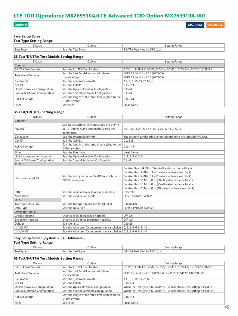
MS269xA MS2830A
Easy Setup ScreenTest Type Setting Range
Display Outline Setting RangeTest Type Sets the Test Type. E-UTRA Test Models, FRC (UL)
BS Test/E-UTRA Test Models Setting RangeDisplay Outline Setting Range
CommonE-UTRA Test Models Sets the E-UTRA Test Models. E-TM1.1, E-TM1.2, E-TM2, E-TM2a, E-TM3.1, E-TM3.1a, E-TM3.2, E-TM3.3
Test Model VersionSets the Test Model version of referred specifications.
3GPP TS 36.141 V8.2.0 (2009-03)3GPP TS 36.141 V9.0.0 (2009-05)
Bandwidth Sets the system bandwidth. 1.4, 3, 5, 10, 15, 20 MHzCell ID Sets the Cell ID. 0 to 153Uplink-downlink Configuration Sets the Uplink-downlink Configuration. 3 fixedSpecial Subframe Configuration Sets the Special Subframe Configuration. 8 fixed
Roll Off LengthSets the length of the ramp time applied to the OFDM symbol.
0 to 144
Filter Sets filter. Ideal, None
BS Test/FRC (UL) Setting RangeDisplay Outline Setting Range
Common
FRC (UL)Selects the setting items described in 3GPP TS 36.141 Annex A and automatically sets the parameters.
A1-1, A1-2, A1-3, A1-4, A1-5, A2-1, A2-2, A2-3
Bandwidth Sets the system bandwidth. The settable bandwidth changes according to the selected FRC (UL).Cell ID Sets the Cell ID. 0 to 503
Roll Off LengthSets the length of the ramp time applied to the OFDM symbol.
0 to 144
Filter Sets the filter type. Ideal, NoneUplink-downlink configuration Sets the Uplink-downlink Configuration. 0, 1, 2, 3, 4, 5, 6Special Subframe Configuration Sets the Special Subframe Configuration. 0 to 8PUSCH
Start Number of RBSets the start position of the RB to which the PUSCH is assigned.
Bandwidth = 1.4 MHz: 0 to (6-allocated resource block)Bandwidth = 3 MHz: 0 to (15-allocated resource block)Bandwidth = 5 MHz: 0 to (25-allocated resource block)Bandwidth = 10 MHz: 0 to (50-allocated resource block)Bandwidth = 15 MHz: 0 to (75-allocated resource block)Bandwidth = 20 MHz: 0 to (100-allocated resource block)
nRNTI Sets the radio network temporary identifier. 0 to FFFFModulation Sets the modulation mode. QPSK, 16QAM, 64QAMUL-SCHTransport Block Size Sets the transport block size for UL-SCH. 0 to 86400Data Type Sets the Data type. PN9fix, PN15fix, All0, All1DMRS for PUSCHGroup Hopping Enables or disables group hopping. Off, OnSequence Hopping Enables or disables Sequence Hopping. Off, OnDelta ss Sets Delta ss. 0 to 29n(1)_DMRS Sets the value used for automatic n_cs calculation. 0, 2, 3, 4, 6, 8, 9, 10n(2)_DMRS Sets the value used for automatic n_cs calculation. 0, 2, 3, 4, 6, 8, 9, 10
Easy Setup Screen (System = LTE-Advanced)Test Type Setting Range
Display Outline Setting RangeTest Type Sets the Test Type E-UTRA Test Models, FRC (UL)
BS Test/E-UTRA Test Models Setting RangeDisplay Outline Setting Range
E-UTRA Test Models Sets the E-UTRA Test Models E-TM1.1, E-TM1.2, E-TM2, E-TM2a, E-TM3.1, E-TM3.1a, E-TM3.2, E-TM3.3
Test Model VersionSets the Test Model version of referred specifications.
3GPP TS 36.141 V8.2.0 (2009-03), 3GPP TS 36.141 V9.0.0 (2009-05)
Bandwidth Sets the system bandwidth 1.4, 3, 5, 10, 15, 20 MHzCell ID Sets the Cell ID 0 to 503Uplink-downlink Configuration Sets the Uplink-downlink configuration When the Test Type is BS Test/E-UTRA Test Models, the setting is fixed to 3.Special Subframe Configuration Sets the Special Subframe configuration When the Test Type is BS Test/E-UTRA Test Models, the setting is fixed to 8.
Roll Off LengthSets the length of the ramp time applied to the OFDM symbol
0 to 144
Filter Sets filter Ideal, None
LTE TDD IQproducer MX269910A/LTE-Advanced TDD Option MX269910A-001Optional
45
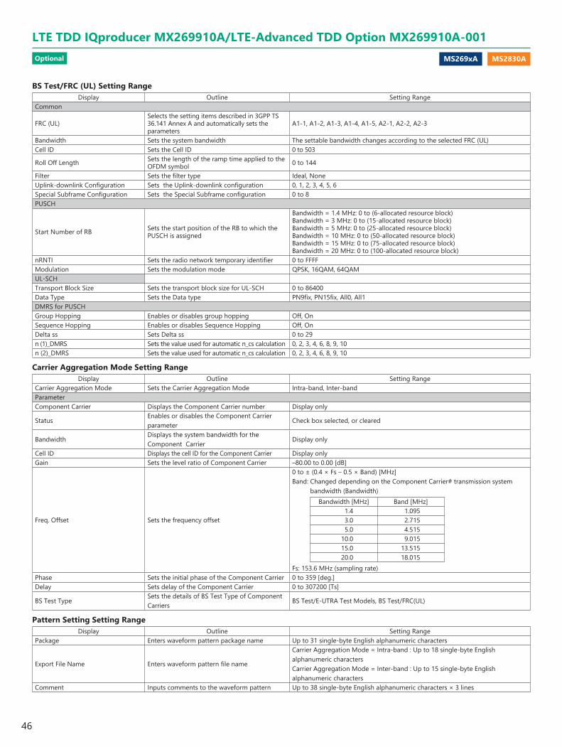
MS269xA MS2830A
BS Test/FRC (UL) Setting RangeDisplay Outline Setting Range
Common
FRC (UL)Selects the setting items described in 3GPP TS 36.141 Annex A and automatically sets the parameters
A1-1, A1-2, A1-3, A1-4, A1-5, A2-1, A2-2, A2-3
Bandwidth Sets the system bandwidth The settable bandwidth changes according to the selected FRC (UL)Cell ID Sets the Cell ID 0 to 503
Roll Off Length Sets the length of the ramp time applied to the OFDM symbol 0 to 144
Filter Sets the filter type Ideal, NoneUplink-downlink Configuration Sets the Uplink-downlink configuration 0, 1, 2, 3, 4, 5, 6Special Subframe Configuration Sets the Special Subframe configuration 0 to 8PUSCH
Start Number of RB Sets the start position of the RB to which the PUSCH is assigned
Bandwidth = 1.4 MHz: 0 to (6-allocated resource block)Bandwidth = 3 MHz: 0 to (15-allocated resource block)Bandwidth = 5 MHz: 0 to (25-allocated resource block)Bandwidth = 10 MHz: 0 to (50-allocated resource block)Bandwidth = 15 MHz: 0 to (75-allocated resource block)Bandwidth = 20 MHz: 0 to (100-allocated resource block)
nRNTI Sets the radio network temporary identifier 0 to FFFFModulation Sets the modulation mode QPSK, 16QAM, 64QAMUL-SCHTransport Block Size Sets the transport block size for UL-SCH 0 to 86400Data Type Sets the Data type PN9fix, PN15fix, All0, All1DMRS for PUSCHGroup Hopping Enables or disables group hopping Off, OnSequence Hopping Enables or disables Sequence Hopping Off, OnDelta ss Sets Delta ss 0 to 29n (1)_DMRS Sets the value used for automatic n_cs calculation 0, 2, 3, 4, 6, 8, 9, 10n (2)_DMRS Sets the value used for automatic n_cs calculation 0, 2, 3, 4, 6, 8, 9, 10
Carrier Aggregation Mode Setting RangeDisplay Outline Setting Range
Carrier Aggregation Mode Sets the Carrier Aggregation Mode Intra-band, Inter-bandParameterComponent Carrier Displays the Component Carrier number Display only
StatusEnables or disables the Component Carrier parameter
Check box selected, or cleared
BandwidthDisplays the system bandwidth for the Component Carrier
Display only
Cell ID Displays the cell ID for the Component Carrier Display onlyGain Sets the level ratio of Component Carrier –80.00 to 0.00 [dB]
Freq. Offset Sets the frequency offset
0 to ± (0.4 × Fs – 0.5 × Band) [MHz]Band: Changed depending on the Component Carrier# transmission system
bandwidth (Bandwidth)Bandwidth [MHz] Band [MHz]
1.4 1.0953.0 2.7155.0 4.515
10.0 9.01515.0 13.51520.0 18.015
Fs: 153.6 MHz (sampling rate)Phase Sets the initial phase of the Component Carrier 0 to 359 [deg.]Delay Sets delay of the Component Carrier 0 to 307200 [Ts]
BS Test TypeSets the details of BS Test Type of Component Carriers
BS Test/E-UTRA Test Models, BS Test/FRC(UL)
Pattern Setting Setting RangeDisplay Outline Setting Range
Package Enters waveform pattern package name Up to 31 single-byte English alphanumeric characters
Export File Name Enters waveform pattern file name
Carrier Aggregation Mode = Intra-band : Up to 18 single-byte English alphanumeric charactersCarrier Aggregation Mode = Inter-band : Up to 15 single-byte English alphanumeric characters
Comment Inputs comments to the waveform pattern Up to 38 single-byte English alphanumeric characters × 3 lines
LTE TDD IQproducer MX269910A/LTE-Advanced TDD Option MX269910A-001Optional
46
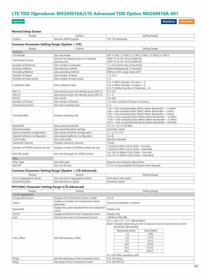
MS269xA MS2830A
Normal Setup ScreenDisplay Outline Setting Range
System Switches 3GPP Systems LTE, LTE-Advanced
Common Parameter Setting Range (System = LTE)Display Outline Setting Range
CommonTest Model Sets test model OFF, E-TM1.1, E-TM1.2, E-TM2, E-TM3.1, E-TM3.2, E-TM3.3
Test Model Version Sets the Test Model version of referred specifications
3GPP TS 36.141 V8.2.0 (2009-03)3GPP TS 36.141 V9.0.0 (2009-05)
Number of Antennas Sets number of antennas 1, 2, 4 (2 and 4 only at Downlink)Diversity Method Sets diversity method Spatial Multiplexing, Tx DiversityPrecoding Method Sets precoding method Without CDD, Large-delay CDDNumber of Layers Sets number of layers 1, 2, 3, 4Number of Code words Sets number of code words 1, 2
Codebook Index Sets codebook index0 to 3 (When Number of Layers = 1)0 to 2 (When Number of Layers = 2)0 to 15 (When Number of Antennas = 4)
NID (1) Sets physical-layer cell-identity group NID (1) 0 to 167NID (2) Sets physical-layer cell-identity group NID (2) 0, 1, 2Cell ID Sets cell ID 0 to 503Number of Frames Sets number of frames 1 to max. number of frames in memoryOversampling Ratio Sets over sampling ratio 2, 4
Sampling Rate Displays sampling rate
1.92 × Over Sampling Ratio [MHz] (When Bandwidth = 1.4 MHz)3.84 × Over Sampling Ratio [MHz] (When Bandwidth = 3 MHz)7.68 × Over Sampling Ratio [MHz] (When Bandwidth = 5 MHz)15.36 × Over Sampling Ratio [MHz] (When Bandwidth = 10 MHz)15.36 × Over Sampling Ratio [MHz] (When Bandwidth = 15 MHz)30.72 × Over Sampling Ratio [MHz] (When Bandwidth = 20 MHz)
Bandwidth Sets system bandwidth 1.4, 3, 5, 10, 15, 20 MHzDownlink/Uplink Sets downlink/uplink settings Downlink, UplinkUplink-downlink Configuration Sets uplink-downlink Configuration 0, 1, 2, 3, 4, 5, 6Special Subframe Configuration Sets special subframe Configuration 0 to 8Cyclic Prefix Sets cyclic prefix Normal, ExtendedSubcarrier Spacing Displays subcarrier spacing 15 kHz
Number of OFDM symbols per slot Displays number of OFDM symbols per slot 7 Symbols (When Cyclic Prefix = Normal)6 Symbols (When Cyclic Prefix = Extended)
Roll Off Length Sets roll-off length for OFDM symbol 0 to 144 Ts (When Cyclic Prefix = Normal)0 to 512 Ts (When Cyclic Prefix = Extended)
FilterFilter Type Sets filter type Nyquist, Root Nyquist, Ideal, NoneRoll Off Sets roll-off rate 0.1 to 1.0 (only enabled for Nyquist, Root Nyquist)
Common Parameter Setting Range (System = LTE-Advanced)Display Outline Setting Range
Carrier Aggregation Mode Sets the Carrier Aggregation Mode Intra-band, Inter-bandDownlink/Uplink Sets downlink or uplink Downlink, Uplink
PHY/MAC Parameter Setting Range (LTE-Advanced)Display Outline Setting Range
Carrier AggregationComponent Carrier Displays the Component Carrier number 0 to 4
Status Enables or disables the Component Carrier parameter Check box selected, or cleared
Bandwidth Displays the system bandwidth for the Component Carrier Display only
Cell ID Displays the Cell ID for the Component Carrier Display onlyGain Sets the level ratio of Component Carrier –80.00 to 0.00 [dB]
Freq. Offset Sets the frequency offset
0 to ± (0.4 × Fs – 0.5 × Band) [MHz]Band: Changed depending on the Component Carrier transmission system
bandwidth (Bandwidth)Bandwidth [MHz] Band [MHz]
1.4 1.0953.0 2.7155.0 4.515
10.0 9.01515.0 13.51520.0 18.015
Fs: 153.6 MHz (sampling rate)Phase Sets the initial phase of the Component Carrier 0 to 359 [deg.]Delay Sets delay of the Component Carrier 0 to 307200 [Ts]
LTE TDD IQproducer MX269910A/LTE-Advanced TDD Option MX269910A-001Optional
47

MS269xA MS2830A
Pattern Setting Parameter Setting RangeDisplay Outline Setting Range
Reference signalPackage Set package name of waveform pattern 31 characters or lessExport File Name Set pattern name of waveform pattern 18 characters or lessLine1 Set comment of waveform pattern 38 characters or lessLine2 Set comment of waveform pattern 38 characters or lessLine3 Set comment of waveform pattern 38 characters or less
Table 1
SubframeUL/DL Configuration
0 1 2 3 4 5 60 D D D D D D D1 S S S S S S S2 U U U U U U U3 U U D U U D U4 U D D U D D U5 D D D D D D D6 S S S D D D S7 U U U D D D U8 U U D D D D U9 U D D D D D D
Table 2UL/DL Configuration Subframe turned "off"
0 –1 0, 52 0, 1, 4, 5, 6, 93 1, 5, 6, 74 0, 1, 4, 5, 6, 75 0, 1, 3, 4, 5, 6, 7, 96 –
Display Outline Setting RangeComponent CarrierTest Model Sets the Test Model OFF, E-TM1.1, E-TM1.2, E-TM2, E-TM3.1, E-TM3.2, E-TM3.3
Test Model Version sets the Test Model version of referred specifications 3GPP TS 36.141 V8.2.0 (2009-03), 3GPP TS 36.141 V9.0.0 (2009-05)
Number of Antennas Sets the number of antennas 1, 2, 4Diversity Method Sets the diversity method Spatial Multiplexing, Tx DiversityPrecoding Method Sets the precoding method Without CDD, Large-delay CDD, Large-delay CDD (Cyclic Precoder Index)Number of Layers Sets the number of layers 1, 2, 3, 4Number of Code words Sets the number of code words 1, 2
Codebook index Sets the codebook index
When Number of Antennas is 2, the setting range varies according to Number of Layers as followsNumber of Layers is 1: 0 to 3Number of Layers is 2: 0 to 2When Number of Antennas is 4: 0 to 15
NID (1) Sets the NID (1) 0 to 167NID (2) Sets the NID (2) 0, 1, 2Cell ID Sets the Cell ID 0 to 503
Number of Frames Sets the number of frames to be generated 1 to the maximum number of frames that can be stored in the equipment's waveform memory
Over Sampling Ratio Sets the oversampling ratio 1, 2, 4
Sampling Rate Displays the sampling rate Display only : It is automatically set according to the Oversampling Ratio and Bandwidth values
Bandwidth Sets the system bandwidth 1.4, 3, 5, 10, 15, 20 MHzDownlink/Uplink Sets downlink or uplink Downlink, UplinkUplink-downlink Configuration Sets the Uplink-downlink Configuration 0, 1, 2, 3, 4, 5, 6Special Subframe Configuration Sets the Special Subframe Configuration 0 to 8Cyclic Prefix Sets the cyclic prefix Normal, ExtendedSubcarrier Spacing Displays the subcarrier spacing (interval) Display onlyNumber of OFDM symbols per slot Sets the number of OFDM symbols per slot Display only
Roll Off LengthSets the length of the ramp time applied to the OFDM symbol
0 to 3152 Ts (in the case of Random Access Preamble)0 to 144 Ts (when Cyclic prefix=Normal)0 to 512 Ts (when Cyclic prefix=Extended)432 Ts (in the case of PRACH)
FilterFilter Type Sets the filter type Nyquist, Root Nyquist, Ideal, NoneRoll Off Sets the roll-off factor 0.1 to 1.0
LTE TDD IQproducer MX269910A/LTE-Advanced TDD Option MX269910A-001Optional
48

MS269xA MS2830A
PHY/MAC Parameter (Downlink) Setting RangeDisplay Outline Setting Range
DownlinkPHICH duration Sets the PHICH area. Normal, Extended
Ng Sets the parameter (Ng) for determining the PHICH arrangement. 1/6, 1/2
Reference SignalFrequency Shift Value Displays frequency shift 0, 1, 2, 3, 4, 5Power Boosting Sets power boosting –20.000 to +20.000 dBPBCHData Status Enable/disables PBCH parameter Disable, EnableData Type Sets data type PN9fix, PN15fix, 16 bit repeat, User File, BCHData Type Repeat Data Sets 16 bit repeat data 0000 to FFFF (only when Data Type = 16 bit repeat)Data Type User File Sets user file Select any file (only when Data Type = User File)Power Boosting Sets power boosting –20.000 to +20.000 dBBCHData Type Sets data type PN9fix, PN15fix, 16 bit repeat, User File, BCCHData Type Repeat Data Sets 16 bit repeat data 0000 to FFFF (only when Data Type = 16 bit repeat)Data Type User File Sets user file Select any file (only when Data Type = User File)
Transport Block Size Sets number of bits required for BCH0 to 1920 bits (When Cyclic Prefix = Normal)0 to 1728 bits (When Cyclic Prefix = Extended)When BCCH is selected for BCH Data Type, the setting is fixed to 24 bits.
DL Bandwidth Displays data mapped to BCCH
n6 (When Bandwidth = 1.4 MHz)n15 (When Bandwidth = 3 MHz)n25 (When Bandwidth = 5 MHz)n50 (When Bandwidth = 10 MHz)n75 (When Bandwidth = 15 MHz)n100 (When Bandwidth = 20 MHz)This is only displayed when BCCH is selected for Data Type of BCH.
PHICH duration Displays the PHICH duration mapped to BCCH Normal, ExtendedThis is only displayed when BCCH is selected for Data Type of BCH.
Ng Displays the Ng value mapped to BCCH 1/6, 1/2, 1, 2This is only displayed when BCCH is selected for Data Type of BCH.
Synchronization SignalsPrimary Synchronization Signal
Data Status Enable/disables primary synchronization signal parameter Disable, Enable
Power Boosting Sets power boosting –20.000 to +20.000 dBSecondary Synchronization Signal
Data Status Enable/disables secondary synchronization signal parameter Disable, Enable
Power Boosting Sets power boosting –20.000 to +20.000 dBSubframe #0 to #9Subframe Type Display subframe type <Table1> (Downlink, Uplink, Special)Virtual Resource Block Type Display virtual resource block type Localized, Distributed
Gap Sets Gap1st Gap, 2nd GapIf Bandwidth is 1.4 MHz, 3 MHz, or 5 MHz, 1st Gap is displayed and Gap cannot be set.If Bandwidth is 10 MHz, 15 MHz, or 20 MHz, 1st Gap or 2nd Gap can be set.
Gap value Displays Gap valueNumber of VRBs Displays the number of VRBPHICH Sets ON/OFF of PHICH ON, OFF (Subframe in Table 2 is turned off by setting UL/DL Configuration)Number of PHICH Groups Displays number of PHICH groups in one subframeNumber of OFDM symbols for PDCCH Sets number of OFDM symbols for PDCCH 1 to 4 Symbol
Total Number of CCEs Display total number of CCEs of control area in subframe
Number of PDCCHs Sets number of PDCCHs 1 to 64CCE Arrangement Sets CCE arrangement PDCCH#0 to (Number of PDCCHs−1), dummyNumber of PDSCHs Sets number of PDSCHs 1 to 64RB Arrangement Sets RB arrangement of PDSCH PDSCH#0 to (Number of PDSCHs−1)PCFICHData Status Enable/disables PCFICH parameter Disable, EnableData Type Sets data type CFI codeword, PN9fix, PN15fix, 16 bit repeat, User FileCFI Sets CFI codeword type 1, 2, 3Data Type Repeat Data Sets 16 bit repeat data 0000 to FFFF (only when Data Type = 16 bit repeat)Data Type User File Sets user file Select any file (only when Data Type = User File)Power Boosting Sets power boosting –20.000 to +20.000 dBPDCCHData Status Enable/disables PDCCH parameter Disable, EnablePDCCH format Sets PDCCH format 0, 1, 2, 3Data Type Sets data type PN9fix, PN15fix, 16 bit repeat, User File, DCIData Type Repeat Data Sets 16 bit repeat data 0000 to FFFF (only when Data Type = 16 bit repeat)Data Type User File Sets user file Select any file (only when Data Type = User File)Power Boosting Set power boosting –20.000 to +20.000 dB
LTE TDD IQproducer MX269910A/LTE-Advanced TDD Option MX269910A-001Optional
49

MS269xA MS2830A
Display Outline Setting RangeDCIData Type Sets data type PN9fix, PN15fix, 16 bit repeat, User FileData Type Repeat Data Sets 16 bit repeat data 0000 to FFFF (only when Data Type = 16 bit repeat)Data Type User File Sets user file Select any file (only when Data Type = User File)Transport Block Size Sets number of bits required for DCI 0 to 576nRNTI Sets radio network temporary identifier 0000 to FFFFPDSCHData Status Enable/disables PDSCH parameter Disable, EnablenRNTI Sets radio network temporary identifier 0000 to FFFFModulation Scheme Sets modulation scheme QPSK, 16QAM, 64QAM, 256QAMData Type Sets data type PN9fix, PN15fix, 16 bit repeat, User File, DL-SCHData Type Repeat Data Sets 16 bit repeat data 0000 to FFFF (only when Data Type = 16 bit repeat)Data Type User File Sets user file Select any file (only when Data Type = User File)Power Boosting Sets power boosting –20.000 to +20.000 dBDL-SCHData Type Sets data type PN9fix, PN15fix, 16 bit repeat, User FileData Type Repeat Data Sets 16 bit repeat data 0000 to FFFF (only when Data Type = 16 bit repeat)Data Type User File Sets user file Select any file (only when Data Type = User File)Transport Block Size Sets number of bits required for DL-SCH 0 to 150000 bitUE Category Sets UE category 1, 2, 3, 4, 5RV Index Sets redundancy version index 0, 1, 2, 3PHICH GroupData Status Enable/disables PHICH parameter Disable, EnableNumber of PHICHs Sets number of PHICH 1 to 8 (Cyclic Prefix = Normal), 1 to 4 (Cyclic Prefix = Extended)Power Boosting Display power boosting of PHICH groupPHICH #0 to # (Number of PHICHs–1)Data Status Enable/disables PHICH parameter Disable, EnableOrthogonal Sequence Index Sets orthogonal sequence index 0 to 7 (When Cyclic Prefix = Normal), 0 to 3 (When Cyclic Prefix = Extended)Data Type Display data type HIHI Sets code word of HI (HARQ indicator) 000, 111Power Boosting Set power boosting –20.000 to +20.000 dB
PHY/MAC Parameter (Uplink) Setting RangeDisplay Outline Setting Range
UplinkData Transmission/PRACH Selects Data Transmission or PRACH Data Transmission, PRACH
DMRS Parameters Sets the calculation method of Demodulation RS parameter. Auto, Manual
PUCCH ParametersDelta PUCCH shift Sets delta PUCCH shift 1, 2, 3
N_CS(1) Sets number of cyclic shift for PUCCH format 1/1a/1b 0 to 7
N_RB(2) Sets number of resource block for PUCCH format 2/2a/2b 0 to 63
Subframe #0 to #9Subframe Type Display subframe type <Table 1> (Downlink, Uplink, Special)Number of PUCCHs Sets number of PUCCHs 0 to 8Number of PUSCHs Sets number of PUSCHs 0 to 8PUCCH #0 to #7Data Status Enables/disables PUCCH parameter Disable, Enablen(1)_PUCCH Sets resource number of PUCCH 1/1a/1b 0 to 764n(2)_PUCCH Sets resource number of PUCCH 2/2a/2b 0 to 764nRNTI Sets radio network temporary identifier 0000 to FFFFPUCCH format Sets PUCCH format 1, 1a, 1b, 2, 2a, 2bData Type Sets data type PN9fix, PN15fix, 16 bit repeat, User File, UCIData Type Repeat Data Sets 16 bit repeat data 0000 to FFFF (only when Data Type = 16 bit repeat)Data Type User File Sets user file Select any file (only when Data Type = User File)Group Hopping Sets enable/disables Disable, Enable
Base Sequence Group Number u Sets base sequence group number
0 to 29When Group Hopping is enabled this parameter becomes invalid and cannot be set.When DMRS Parameters is Auto, only calculated value displays and nothing can be set.
Base Sequence Number v Displays base sequence number 0 fixedPower Boosting Sets power boosting –20.000 to +20.000 dB
LTE TDD IQproducer MX269910A/LTE-Advanced TDD Option MX269910A-001Optional
50
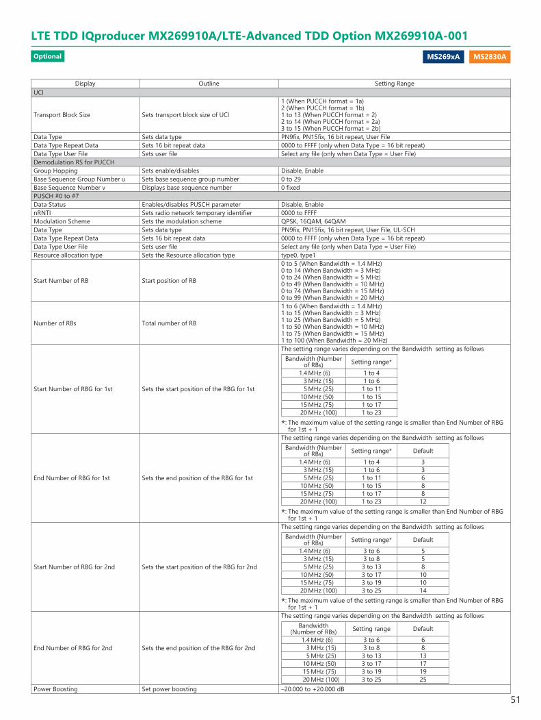
MS269xA MS2830A
Display Outline Setting RangeUCI
Transport Block Size Sets transport block size of UCI
1 (When PUCCH format = 1a)2 (When PUCCH format = 1b)1 to 13 (When PUCCH format = 2)2 to 14 (When PUCCH format = 2a)3 to 15 (When PUCCH format = 2b)
Data Type Sets data type PN9fix, PN15fix, 16 bit repeat, User FileData Type Repeat Data Sets 16 bit repeat data 0000 to FFFF (only when Data Type = 16 bit repeat)Data Type User File Sets user file Select any file (only when Data Type = User File)Demodulation RS for PUCCHGroup Hopping Sets enable/disables Disable, EnableBase Sequence Group Number u Sets base sequence group number 0 to 29Base Sequence Number v Displays base sequence number 0 fixedPUSCH #0 to #7Data Status Enables/disables PUSCH parameter Disable, EnablenRNTI Sets radio network temporary identifier 0000 to FFFFModulation Scheme Sets the modulation scheme QPSK, 16QAM, 64QAMData Type Sets data type PN9fix, PN15fix, 16 bit repeat, User File, UL-SCHData Type Repeat Data Sets 16 bit repeat data 0000 to FFFF (only when Data Type = 16 bit repeat)Data Type User File Sets user file Select any file (only when Data Type = User File)Resource allocation type Sets the Resource allocation type type0, type1
Start Number of RB Start position of RB
0 to 5 (When Bandwidth = 1.4 MHz)0 to 14 (When Bandwidth = 3 MHz)0 to 24 (When Bandwidth = 5 MHz)0 to 49 (When Bandwidth = 10 MHz)0 to 74 (When Bandwidth = 15 MHz)0 to 99 (When Bandwidth = 20 MHz)
Number of RBs Total number of RB
1 to 6 (When Bandwidth = 1.4 MHz)1 to 15 (When Bandwidth = 3 MHz)1 to 25 (When Bandwidth = 5 MHz)1 to 50 (When Bandwidth = 10 MHz)1 to 75 (When Bandwidth = 15 MHz)1 to 100 (When Bandwidth = 20 MHz)
Start Number of RBG for 1st Sets the start position of the RBG for 1st
The setting range varies depending on the Bandwidth setting as followsBandwidth (Number
of RBs) Setting range* 1.4 MHz (6) 1 to 4 3 MHz (15) 1 to 6 5 MHz (25) 1 to 11 10 MHz (50) 1 to 15 15 MHz (75) 1 to 17 20 MHz (100) 1 to 23
*: The maximum value of the setting range is smaller than End Number of RBG for 1st + 1
End Number of RBG for 1st Sets the end position of the RBG for 1st
The setting range varies depending on the Bandwidth setting as followsBandwidth (Number
of RBs) Setting range* Default 1.4 MHz (6) 1 to 4 3 3 MHz (15) 1 to 6 3 5 MHz (25) 1 to 11 6 10 MHz (50) 1 to 15 8 15 MHz (75) 1 to 17 8 20 MHz (100) 1 to 23 12
*: The maximum value of the setting range is smaller than End Number of RBG for 1st + 1
Start Number of RBG for 2nd Sets the start position of the RBG for 2nd
The setting range varies depending on the Bandwidth setting as followsBandwidth (Number
of RBs) Setting range* Default 1.4 MHz (6) 3 to 6 5 3 MHz (15) 3 to 8 5 5 MHz (25) 3 to 13 8 10 MHz (50) 3 to 17 10 15 MHz (75) 3 to 19 10 20 MHz (100) 3 to 25 14
*: The maximum value of the setting range is smaller than End Number of RBG for 1st + 1
End Number of RBG for 2nd Sets the end position of the RBG for 2nd
The setting range varies depending on the Bandwidth setting as followsBandwidth
(Number of RBs) Setting range Default 1.4 MHz (6) 3 to 6 6 3 MHz (15) 3 to 8 8 5 MHz (25) 3 to 13 13 10 MHz (50) 3 to 17 17 15 MHz (75) 3 to 19 19 20 MHz (100) 3 to 25 25
Power Boosting Set power boosting –20.000 to +20.000 dB
LTE TDD IQproducer MX269910A/LTE-Advanced TDD Option MX269910A-001Optional
51

MS269xA MS2830A
Display Outline Setting RangeUL-SCHTransport Block Size Sets transport block size of UL-SCH 0 to 86400Data Type Sets data type PN9fix, PN15fix, 16 bit repeat, User FileData Type Repeat Data Sets 16 bit repeat data 0000 to FFFF (only when Data Type = 16 bit repeat)Data Type User File Sets user file Select any file (only when Data Type = User File)RV Index Sets redundancy version index 0, 1, 2, 3HARQ-ACKData Status This enables or disables HARQ-ACK Disable, Enable
Data Type Sets the Data type to be inserted into the HARQ-ACK ACK, NACK, ACK-ACK, ACK-NACK, NACK-ACK, NACK-NACK
Total Number of Coded Bits Sets the number of bits after HARQ-ACK encoding 0 to Number of RBs × 288RIData Status Enables or disables the RI Disable, EnableData Type Sets the Data type to be inserted into the RI 1 (1 bit), 2 (1 bit), 1 (2 bits), 2 (2 bits), 3 (2 bits), 4 (2 bits)Total Number of Coded Bits Sets the number of bits after RI encoding 0 to Number of RBs × 288CQI/PMIData Status Enables or disables the CQI/PMI Disable, EnableData Type Sets the Data type to be inserted into the CQI/PMI PN9fix, PN15fix, 16 bit repeat, User File
Data Type Repeat Data Sets the 16 bit repeat data to be inserted into the CQI/PMI 0000 to FFFF (only when Data Type = 16 bit repeat)
Data Type User File Sets the User type to be inserted into the CQI/PMI Select any file (only when Data Type = User File)
Total Number of Coded Bits Sets the number of bits after CQI/PMI encoding 0 to 86400Demodulation RS for PUSCHGroup Hopping Sets enable/disables Disable, EnableSequence Hopping Sets enable/disables Disable, EnableDelta ss Sets delta ss 0 to 29Base Sequence Group Number u Sets base sequence group number 0 to 29Base Sequence Number v Displays base sequence number 0, 1Cyclic Shift 1st slotn_cs Sets n_cs of first slot of demodulation RS 0 to 11
alpha Sets cyclic shift of first slot of demodulation RSAlpha is calculated by the following expression. Five digits below the decimal are displayed.alpha = 2 × pi × n_cs/12
Cyclic Shift 2nd slotn_cs Sets n_cs of second slot of demodulation RS 0 to 11
alpha Sets cyclic shift of second slot of demodulation RS
Alpha is calculated by the following expression. Five digits below the decimal are displayed.alpha = 2 × pi × n_cs/12
PRACH
PRACH Configuration Sets the transmission timing for PRACH
The settable values for PRACH Configuration are determined according to Uplink-downlink Configuration as the table below. However, the setup of PRACH Configuration from 48 to 57 is only available in the following conditions: Cyclic Prefix is Normal and Special Subframe Configuration is from 5 to 8, or Cyclic Prefix is Extended and Special Subframe Configuration is from 4 to 6.
Uplink-downlink Configuration Settable values for PRACH Configuration
0 0 to 10, 12 to 18, 20 to 571 0 to 7, 9 to 12, 15 to 39, 48 to 572 0 to 4, 6, 9, 10, 12, 15, 16, 18, 48 to 573 0 to 9, 12 to 18, 20, 21, 23, 25 to 31, 33, 35 to 41, 43, 45 to 49, 51, 53 to 574 0 to 4, 6, 9, 10, 12, 15, 16, 18, 20, 21, 23, 25 to 31, 33, 35 to 39, 48, 49, 51, 53
to 575 0, 1, 3, 6, 9, 12, 15, 18, 48, 49, 51, 53 to 576 0 to 15, 18 to 41, 43, 45 to 57
Number of PRACH Resources Displays the number of PRACH Resources Depending on the PRACH ConfigurationPRACH Resource #0 to #5Data Status Enables or disables the PRACH Resource # Disable, Enable
Preamble Format Displays the Preamble Format which decides the length in the time axis of PRACH Resource # Depending on the PRACH Configuration
Frequency Resource IndexDisplays Frequency Resource Index which decides the position in the frequency axis of PRACH Resource #
Depending on the PRACH Configuration, Uplink-downlink Configuration, PRACH Resource#"
Transmit FrameDisplays Transmit Frame which decides the arrangement method of PRACH Resource# in the frame
Depending on the PRACH Configuration, Uplink-downlink Configuration, PRACH Resource#"
Subframe Number Displays the subframe number that PRACH Resource# transmits
Depending on the PRACH Configuration, Uplink-downlink Configuration, PRACH Resource#"
Logical Root Sequence Number Sets Logical Root Sequence Number that decides the value of Physical Root Sequence Number.
When Preamble Format is 0, 1, 2, 3: 0 to 837 When Preamble Format is 4: 0 to 137
Physical Root Sequence Number Displays Physical Root Sequence Number used to calculate Cyclic Shift value depending on the Logical Root Sequence Number
Cyclic Shift Set Sets how to calculate Cyclic Shift value Unrestricted, Restrictedv Sets v value used to calculate Cyclic Shift value 0 to 63
LTE TDD IQproducer MX269910A/LTE-Advanced TDD Option MX269910A-001Optional
52
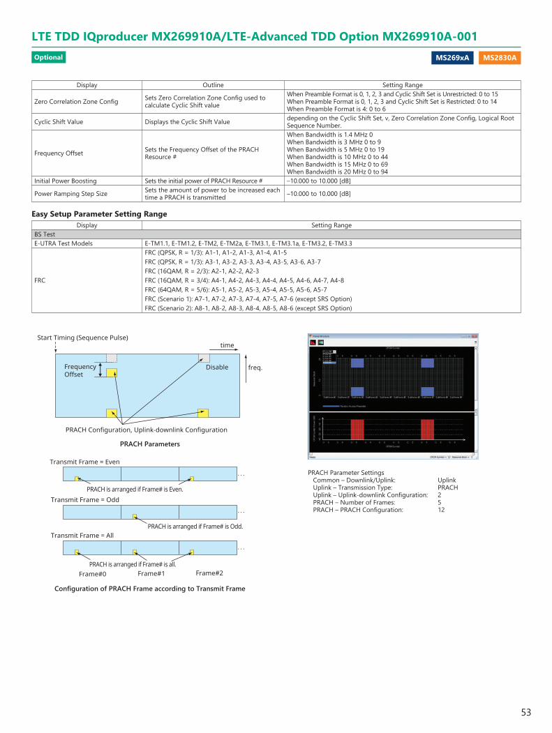
MS269xA MS2830A
Display Outline Setting Range
Zero Correlation Zone Config Sets Zero Correlation Zone Config used to calculate Cyclic Shift value
When Preamble Format is 0, 1, 2, 3 and Cyclic Shift Set is Unrestricted: 0 to 15 When Preamble Format is 0, 1, 2, 3 and Cyclic Shift Set is Restricted: 0 to 14 When Preamble Format is 4: 0 to 6
Cyclic Shift Value Displays the Cyclic Shift Value depending on the Cyclic Shift Set, v, Zero Correlation Zone Config, Logical Root Sequence Number.
Frequency Offset Sets the Frequency Offset of the PRACH Resource #
When Bandwidth is 1.4 MHz 0 When Bandwidth is 3 MHz 0 to 9 When Bandwidth is 5 MHz 0 to 19 When Bandwidth is 10 MHz 0 to 44 When Bandwidth is 15 MHz 0 to 69 When Bandwidth is 20 MHz 0 to 94
Initial Power Boosting Sets the initial power of PRACH Resource # –10.000 to 10.000 [dB]
Power Ramping Step Size Sets the amount of power to be increased each time a PRACH is transmitted –10.000 to 10.000 [dB]
Easy Setup Parameter Setting RangeDisplay Setting Range
BS TestE-UTRA Test Models E-TM1.1, E-TM1.2, E-TM2, E-TM2a, E-TM3.1, E-TM3.1a, E-TM3.2, E-TM3.3
FRC
FRC (QPSK, R = 1/3): A1-1, A1-2, A1-3, A1-4, A1-5FRC (QPSK, R = 1/3): A3-1, A3-2, A3-3, A3-4, A3-5, A3-6, A3-7FRC (16QAM, R = 2/3): A2-1, A2-2, A2-3FRC (16QAM, R = 3/4): A4-1, A4-2, A4-3, A4-4, A4-5, A4-6, A4-7, A4-8FRC (64QAM, R = 5/6): A5-1, A5-2, A5-3, A5-4, A5-5, A5-6, A5-7FRC (Scenario 1): A7-1, A7-2, A7-3, A7-4, A7-5, A7-6 (except SRS Option)FRC (Scenario 2): A8-1, A8-2, A8-3, A8-4, A8-5, A8-6 (except SRS Option)
Start Timing (Sequence Pulse)
freq.
time
PRACH Configuration, Uplink-downlink Configuration
Frequency Offset
Disable
Transmit Frame = Even
Transmit Frame = Odd
Transmit Frame = All
Frame#0 Frame#1 Frame#2
PRACH is arranged if Frame# is Odd.
PRACH is arranged if Frame# is all.
PRACH is arranged if Frame# is Even.
. . .
. . .
. . .
PRACH Parameter SettingsCommon – Downlink/Uplink: UplinkUplink – Transmission Type: PRACHUplink – Uplink-downlink Configuration: 2PRACH – Number of Frames: 5PRACH – PRACH Configuration: 12
PRACH Parameters
Configuration of PRACH Frame according to Transmit Frame
LTE TDD IQproducer MX269910A/LTE-Advanced TDD Option MX269910A-001Optional
53
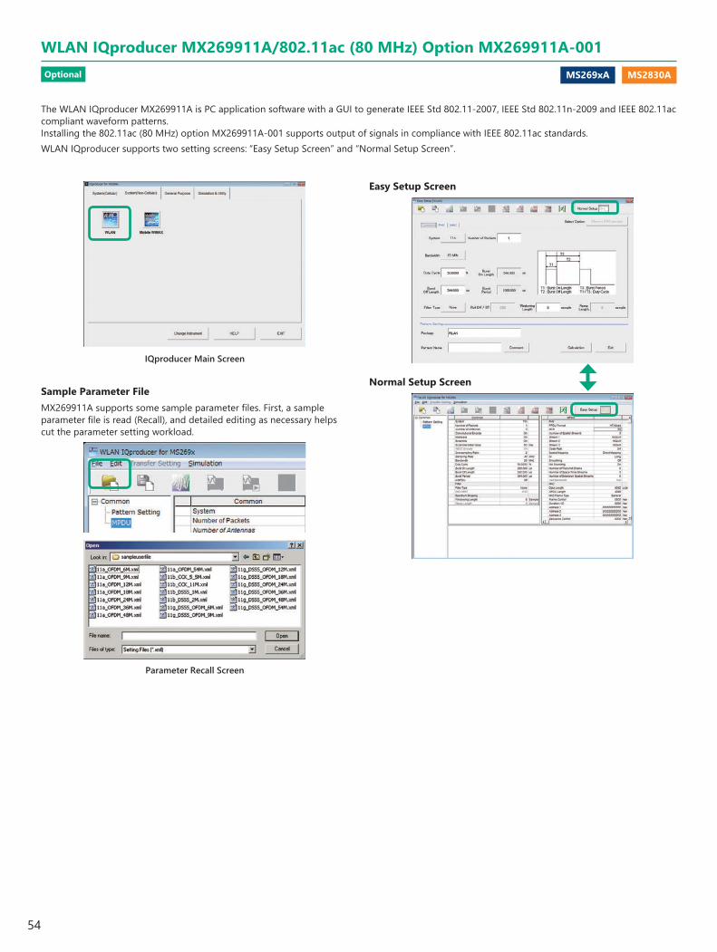
MS269xA MS2830A
The WLAN IQproducer MX269911A is PC application software with a GUI to generate IEEE Std 802.11-2007, IEEE Std 802.11n-2009 and IEEE 802.11ac compliant waveform patterns.Installing the 802.11ac (80 MHz) option MX269911A-001 supports output of signals in compliance with IEEE 802.11ac standards.WLAN IQproducer supports two setting screens: “Easy Setup Screen” and “Normal Setup Screen”.
Easy Setup Screen
Normal Setup Screen
IQproducer Main Screen
Sample Parameter FileMX269911A supports some sample parameter files. First, a sample parameter file is read (Recall), and detailed editing as necessary helps cut the parameter setting workload.
Parameter Recall Screen
WLAN IQproducer MX269911A/802.11ac (80 MHz) Option MX269911A-001Optional
54
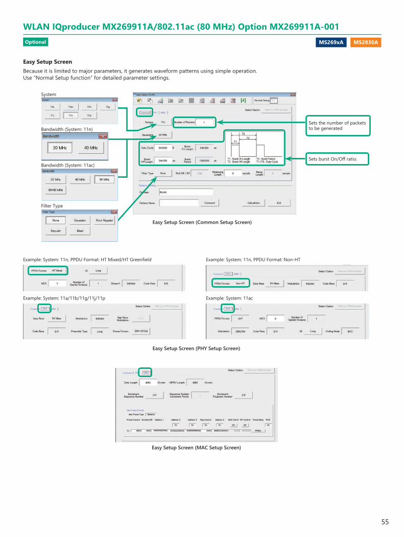
MS269xA MS2830A
Easy Setup ScreenBecause it is limited to major parameters, it generates waveform patterns using simple operation. Use “Normal Setup function” for detailed parameter settings.
Easy Setup Screen (MAC Setup Screen)
Easy Setup Screen (PHY Setup Screen)
Example: System: 11n, PPDU Format: HT Mixed/HT Greenfield Example: System: 11n, PPDU Format: Non-HT
Example: System: 11a/11b/11g/11j/11p Example: System: 11ac
Easy Setup Screen (Common Setup Screen)
System
Filter Type
Sets the number of packets to be generated
Sets burst On/Off ratio.Bandwidth (System: 11ac)
Bandwidth (System: 11n)
WLAN IQproducer MX269911A/802.11ac (80 MHz) Option MX269911A-001Optional
55
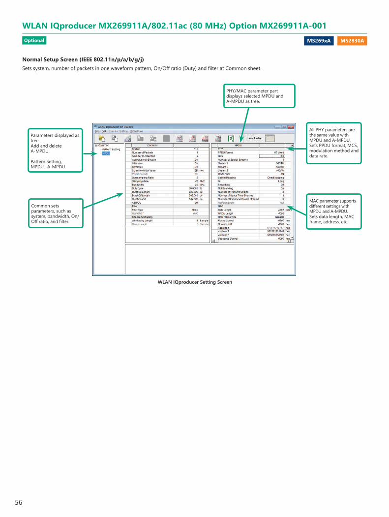
MS269xA MS2830A
Normal Setup Screen (IEEE 802.11n/p/a/b/g/j)Sets system, number of packets in one waveform pattern, On/Off ratio (Duty) and filter at Common sheet.
WLAN IQproducer Setting Screen
Common sets parameters, such as system, bandwidth, On/Off ratio, and filter.
All PHY parameters are the same value with MPDU and A-MPDU.Sets PPDU format, MCS, modulation method and data rate.
MAC parameter supports different settings with MPDU and A-MPDU.Sets data length, MAC frame, address, etc.
Parameters displayed as tree.Add and delete A-MPDU.
Pattern Setting, MPDU, A-MPDU
PHY/MAC parameter part displays selected MPDU and A-MPDU as tree.
WLAN IQproducer MX269911A/802.11ac (80 MHz) Option MX269911A-001Optional
56
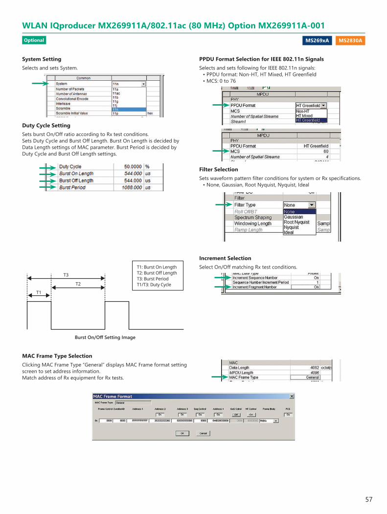
MS269xA MS2830A
T3
T2
T1
T1: Burst On LengthT2: Burst Off LengthT3: Burst PeriodT1/T3: Duty Cycle
Burst On/Off Setting Image
Increment SelectionSelect On/Off matching Rx test conditions.
MAC Frame Type SelectionClicking MAC Frame Type “General” displays MAC Frame format setting screen to set address information.Match address of Rx equipment for Rx tests.
System SettingSelects and sets System.
Duty Cycle SettingSets burst On/Off ratio according to Rx test conditions.Sets Duty Cycle and Burst Off Length. Burst On Length is decided by Data Length settings of MAC parameter. Burst Period is decided by Duty Cycle and Burst Off Length settings.
PPDU Format Selection for IEEE 802.11n SignalsSelects and sets following for IEEE 802.11n signals:
• PPDU format: Non-HT, HT Mixed, HT Greenfield• MCS: 0 to 76
Filter SelectionSets waveform pattern filter conditions for system or Rx specifications.
• None, Gaussian, Root Nyquist, Nyquist, Ideal
WLAN IQproducer MX269911A/802.11ac (80 MHz) Option MX269911A-001Optional
57
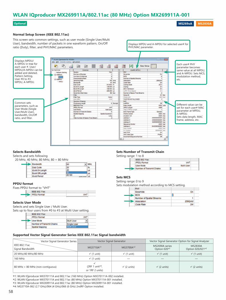
MS269xA MS2830A
Normal Setup Screen (IEEE 802.11ac)This screen sets common settings, such as user mode (Single User/Multi User), bandwidth, number of packets in one waveform pattern, On/Off ratio (Duty), filter, and PHY/MAC parameters.
Common sets parameters, such asUser Mode (Single User/Multi User), bandwidth, On/Off ratio, and filter.
Each user# PHY parameter becomes same value at all MPDU, and A-MPDU. Sets MCS, modulation method, etc.
Different value can be set for each user# MAC parameter at MPDU, A-MPDU.Sets data length, MAC frame, address, etc.
Displays MPDU/A-MPDU in tree for each user #. User/MPDU/A-MPDU can be added and deleted. Pattern Setting,User #0 to #3MPDU, A-MPDU.
Displays MPDU and A-MPDU for selected user# for PHY/MAC parameter.
Selects BandwidthSelects and sets following
20 MHz, 40 MHz, 80 MHz, 80 + 80 MHz
PPDU formatFixes PPDU format to “VHT”
Selects User ModeSelects and sets Single User / Multi User.Sets up to four users from #0 to #3 at Multi User setting.
Sets Number of Transmit ChainSetting range: 1 to 8
Sets MCSSetting range: 0 to 9Sets modulation method according to MCS setting.
Supported Vector Signal Generator Series IEEE 802.11ac Signal bandwidth
Vector Signal Generator SeriesIEEE 802.11acSignal Bandwidth
Vector Signal Generator Vector Signal Generator Option for Signal Analyzer
MG3710A*1 MG3700A*2 MS2690A seriesOption 020*3
MS2830AOption 020/021*3
20 MHz/40 MHz/80 MHz (1 unit) (1 unit) (1 unit) (1 unit)
160 MHz (1 unit) — — —
80 MHz + 80 MHz (non-contiguous)
(2RF 1 unit*4, or 1RF 2 units)
(2 units) (2 units) (2 units)
*1: WLAN IQproducer MX370111A and 802.11ac (160 MHz) Option MX370111A-002 installed.*2: WLAN IQproducer MX370111A and 802.11ac (80 MHz) Option MX370111A-001 installed.*3: WLAN IQproducer MX269911A and 802.11ac (80 MHz) Option MX269911A-001 installed.*4: MG3710A-062 (2.7 GHz)/064 (4 GHz)/066 (6 GHz) 2ndRF Option installed.
WLAN IQproducer MX269911A/802.11ac (80 MHz) Option MX269911A-001Optional
58
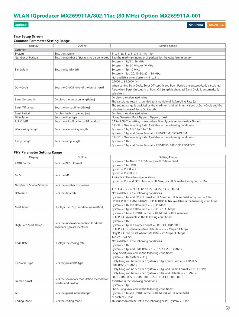
MS269xA MS2830A
Easy Setup ScreenCommon Parameter Setting Range
Display Outline Setting RangeCommonSystem Sets the system 11a, 11ac, 11b, 11g, 11j, 11n, 11pNumber of Packets Sets the number of packets to be generated 1 to the maximum number of packets for the waveform memory
Bandwidth Sets the bandwidth
System = 11a/11j: 20 MHzSystem = 11n: 20 MHz or 40 MHzSystem = 11p: 10 MHzSystem = 11ac: 20, 40, 80, 80 + 80 MHzNot available when System = 11b, 11g
Duty Cycle Sets the On/Off ratio of the burst signal
0.1000 to 99.0000 [%] When setting Duty Cycle, Burst Off Length and Burst Period are automatically calculated. Also, when Burst On Length or Burst Off Length is changed, Duty Cycle is automatically calculated
Burst On Length Displays the burst on length [us]Displays the calculated value The calculated result is rounded to a multiple of 1/Sampling Rate [µs]
Burst Off Length Sets the burst off length [us]The setting range is decided by the maximum and minimum values of Duty Cycle and the calculated value of Burst On Length
Burst Period Display the burst period [us] Displays the calculated valueFilter Type Sets the filter type None, Gaussian, Root Nyquist, Nyquist, IdealRoll Off/BT Sets the roll-off factor or BT product 0.1 to 1.00 (The setting is fixed when Filter Type is set to Ideal or None)
Windowing Length Sets the windowing length0 to 32 × Oversampling Rate: Available in the following conditions:System = 11a, 11j, 11p, 11n, 11acSystem = 11g, and Frame Format = ERP-OFDM, DSSS-OFDM
Ramp Length Sets the ramp length0 to 16 × Oversampling Rate: Available in the following conditions:System = 11bSystem = 11g, and Frame Format = ERP-DSSS, ERP-CCK, ERP-PBCC
PHY Parameter Setting RangeDisplay Outline Setting Range
PPDU Format Sets the PPDU FormatSystem = 11n: Non-HT, HT-Mixed, and HT-Greenfield System = 11ac: VHT
MCS Sets the MCS
System = 11n: 0 to 7System = 11ac: 0 to 9Available in the following conditions:System = 11n, and PPDU Format = HT Mixed, or HT Greenfield, or System = 11ac
Number of Spatial Streams Sets the number of streams
Data Rate Sets the data rate1, 2, 3, 4.5, 5.5, 6, 9, 11, 12, 18, 22, 24, 27, 33, 36, 48, 54Not available in the following conditions:System = 11n, and PPDU Format = HT Mixed or HT Greenfield, or System = 11ac
Modulation Displays the PSDU modulation method
BPSK, QPSK, 16QAM, 64QAM, DBPSK, DQPSK: Not available in the following conditions:System = 11b and Data Rate = 5.5, 11 MbpsSystem = 11g and Data Rate = 5.5, 11, 22, 33 MbpsSystem = 11n and PPDU Format = HT Mixed or HT Greenfield
High Rate ModulationSets the modulation method for direct sequence spread spectrum
CCK, PBCC: Available in the following conditions:System = 11bSystem = 11g and Frame Format = ERP-CCK, ERP-PBCCCCK, PBCC is selectable when Data Rate = 5.5 Mbps, 11 MbpsOnly PBCC can be set when Data Rate = 22 Mbps, 33 Mbps
Code Rate Displays the coding rate
1/2, 2/3, 3/4, 5/6Not available in the following conditions:System = 11b System = 11g, and Data Rate = 1, 2, 5.5, 11, 22, 33 Mbps.
Preamble Type Sets the preamble type
Long, Short: Available in the following conditions: System = 11b, System = 11g (Only Long can be set when System = 11g, Frame Format = ERP-DSSS, Data Rate = 1 Mbps) (Only Long can be set when System = 11g, and Frame Format = ERP-OFDM) (Only Long can be set when System = 11b, and Data Rate = 1 Mbps)
Frame FormatSets the secondary modulation method for header and payload
ERP-OFDM, DSSS-OFDM, ERP-DSSS, ERP-CCK, ERP-PBCC: Available in the following conditions: System = 11g
GI Sets the guard interval lengthShort, Long: Available in the following conditions:System = 11n and PPDU Format = HT Mixed, or HT Greenfieldor System = 11ac
Coding Mode Sets the coding mode This function can be set in the following cases: System = 11ac
WLAN IQproducer MX269911A/802.11ac (80 MHz) Option MX269911A-001Optional
59
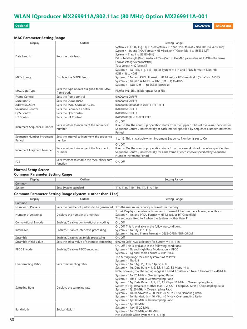
MS269xA MS2830A
MAC Parameter Setting RangeDisplay Outline Setting Range
Data Length Sets the data length
System = 11a, 11b, 11g, 11j, 11p, or System = 11n and PPDU format = Non-HT: 1 to (4095–Diff) System = 11n, and PPDU Format = HT Mixed, or HT Greenfield: 1 to (65535–Diff) System = 11ac: 1 to (65535–Diff)Diff = Total Length (Mac Header + FCS) – (Sum of the MAC parameters set to Off in the Frame Format setting screen [octet(s)])Total Length = 40 [octet(s)]
MPDU Length Displays the MPDU length
System = 11a, 11b, 11g, 11j, 11p, or System = 11n and PPDU format = Non-HT:(Diff + 1) to 4095 System = 11n, and PPDU Format = HT Mixed, or HT Greenfi eld: (Diff+1) to 65535 System = 11n, and A-MPDU = ON: (Diff + 1) to 4095 System = 11ac: (Diff+1) to 65535 [octet(s)]
MAC Data Type Sets the type of data assigned to the MAC frame body PN9fix, PN15fix, 16 bit repeat, User File
Frame Control Sets the frame control 0x0000 to 0xFFFFDuration/ID Sets the Duration/ID 0x0000 to 0xFFFFAddress1/2/3/4 Sets the MAC Address1/2/3/4 0x0000 0000 0000 to 0xFFFF FFFF FFFFSequence Control Sets the Sequence Control 0x0000 to 0xFFFFQoS Control Sets the QoS Control 0x0000 to 0xFFFFHT Control Sets the HT Control 0x0000 0000 to 0xFFFF FFFF
Increment Sequence Number Sets whether to increment the sequence number
On, Off If set to On, the count-up operation starts from the upper 12 bits of the value specified for Sequence Control, incrementally at each interval specified by Sequence Number Increment Period
Sequence Number Increment Period
Sets the interval to increment the sequence number 1 to 15: This is available when Increment Sequence Number is set to On
Increment Fragment Number Sets whether to increment the Fragment Number
On, Off If set to On, the count-up operation starts from the lower 4 bits of the value specified for Sequence Control, incrementally for each frame at each interval specified by Sequence Number Increment Period
FCS Sets whether to enable the MAC check sum function On, Off
Normal Setup Screen Common Parameter Setting Range
Display Outline Setting RangeCommonSystem Sets System standard 11a, 11ac, 11b, 11g, 11j, 11n, 11p
Common Parameter Setting Range (System = other than 11ac)Display Outline Setting Range
CommonNumber of Packets Sets the number of packets to be generated 1 to the maximum capacity of waveform memory
Number of Antennas Displays the number of antennas1 to 4: Displays the value of Number of Transmit Chains in the following conditions:System = 11n, and PPDU Format = HT Mixed, or HT Greenfield The setting is fixed to 1 when the System is other than 11n.
Convolutional Encode Enables/Disables convolutional encoding On, Off
Interleave Enables/Disables interleave processingOn, Off: This is available in the following conditions:System = 11a, 11j, 11n, 11p, System = 11g, and Frame Format = DSSS-OFDM/ERP-OFDM
Scramble Enables/Disables scramble processing On, OffScramble Initial Value Sets the initial value of scramble processing 0x00 to 0x7F: Available only for System = 11a, 11n
PBCC Encode Enables/Disables PBCC encodingOn, Off: This is available in the following conditions:System = 11b and High Rate Modulation = PBCC System = 11g and Frame Format = ERP-PBCC
Oversampling Ratio Sets oversampling ratio
The setting range for each system is as follows:System = 11b: 4, 8 System = 11a, 11g, 11j, 11n, 11p : 2, 4, 8 System = 11g, Data Rate = 1, 2, 5.5, 11, 22, 33 Mbps : 4, 8Note, however, that the setting range is 2 and 4 if System = 11n and Bandwidth = 40 MHz
Sampling Rate Displays the sampling rate
System = 11a: 20 MHz × Oversampling Ratio System = 11b: 11 MHz × Oversampling RatioSystem = 11g, Data Rate = 1, 2, 5.5, 11 Mbps: 11 MHz × Oversampling RatioSystem = 11g, Data Rate = other than 1, 2, 5.5, 11 Mbps: 20 MHz × Oversampling RatioSystem = 11j: 20 MHz × Oversampling RatioSystem = 11n, Bandwidth = 20 MHz: 20 MHz × Oversampling RatioSystem = 11n, Bandwidth = 40 MHz: 40 MHz × Oversampling RatioSystem = 11p: 10 MHz × Oversampling Ratio
Bandwidth Set bandwidth
System = 11p: 10 MHzSystem = 11a/11j: 20 MHzSystem = 11n: 20 MHz or 40 MHzNot available when System = 11b, 11g
WLAN IQproducer MX269911A/802.11ac (80 MHz) Option MX269911A-001Optional
60
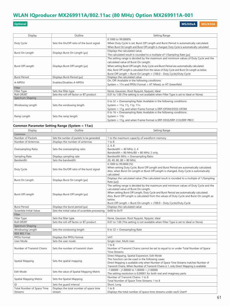
MS269xA MS2830A
Display Outline Setting Range
Duty Cycle Sets the On/Off ratio of the burst signal0.1000 to 99.0000% When Duty Cycle is set, Burst Off Length and Burst Period is automatically calculated. When Burst On Length and Burst Off Length is changed, Duty Cycle is automatically calculated
Burst On Length Displays Burst On Length [μs]Displays the calculated value.The calculated result is rounded to a multiple of 1/Sampling Rate [μs]
Burst Off Length Displays Burst Off Length [μs]
The setting range is decided by the maximum and minimum values of Duty Cycle and the calculated value of Burst On Length. When setting Burst Off Length, Duty Cycle and Burst Period are automatically calculated. Also, Burst Off Length is calculated from the values of Duty Cycle and Burst On Length as below. Burst Off Length = Burst On Length × (100.0 – Duty Cycle)/Duty Cycle
Burst Period Displays Burst Period [μs] Displays the calculated value
A-MPDU Enables/Disables A-MPDUOn, Off: Available in the following conditions:System = 11n and PPDU Format = HT Mixed, or HT Greenfield
FilterFilter Type Sets the filter type None, Gaussian, Root Nyquist, Nyquist, IdealRoll Off/BT Sets the roll-off factor or BT product 0.01 to 1.00 (The setting is not available when Filter Type is set to Ideal or None) Spectrum Shaping
Windowing Length Sets the windowing length0 to 32 × Oversampling Rate: Available in the following conditions:System = 11a, 11j, 11p, 11n System = 11g, and when Frame Format is ERP-OFDM/DSSS-OFDM
Ramp Length Sets the ramp length0 to 16 × Oversampling Rate: Available in the following conditions:System = 11b System = 11g, and when Frame Format is ERP-DSSS/ERP-CCK/ERP-PBCC
Common Parameter Setting Range (System = 11ac)Display Outline Setting Range
CommonNumber of Packets Sets the number of packets to be generated 1 to the maximum capacity of waveform memoryNumber of Antennas Displays the number of antennas 1 to 8
Oversampling Ratio Sets the oversampling ratio2, 4, 8 Bandwidth = 40 MHz: 2, 4 Bandwidth = 80 MHz/80 + 80 MHz: 2 only.
Sampling Rate Displays sampling rate Bandwidth MHz × Oversampling RatioBandwidth Sets the bandwidth 20, 40, 80, 80 + 80 MHz
Duty Cycle Sets the On/Off ratio of the burst signal
0.1000 to 99.0000 [%] When setting Duty Cycle, Burst Off Length and Burst Period are automatically calculated. Also, when Burst On Length or Burst Off Length is changed, Duty Cycle is automatically calculated
Burst On Length Displays Burst On Length [μs] Displays the calculated value (The calculated result is rounded to a multiple of 1/Sampling Rate [µs])
Burst Off Length Displays Burst Off Length [μs]
The setting range is decided by the maximum and minimum values of Duty Cycle and the calculated value of Burst On Length. When setting Burst Off Length, Duty Cycle and Burst Period are automatically calculated. Also, Burst Off Length is calculated from the values of Duty Cycle and Burst On Length as below. Burst Off Length = Burst On Length × (100.0 – Duty Cycle)/Duty Cycle
Burst Period Displays the burst period [μs] Displays the calculated valueScramble Initial Value Sets the initial value of scramble processing 0x00 to 0x7FFilterFilter Type Sets the filter type None, Gaussian, Root Nyquist, Nyquist, IdealRoll Off/BT Sets the roll-off factor or BT product 0.01 to 1.00 (The setting is not available when Filter Type is set to Ideal or None)Spectrum ShapingWindowing Length Sets the windowing length 0 to 32 × Oversampling RateIEEE 802.11acPPDU Format Displays the PPDU format VHTUser Mode Sets the user mode Single User, Multi User
Number of Transmit Chains Sets the number of transmit chain1 to 8 Number of Transmit Chains cannot be set to equal to or under Total Number of Space Time Streams
Spatial Mapping Sets the spatial mapping
Direct Mapping, Spatial Expansion, Edit Mode This function can be used in the following cases: Direct Mapping is available only when Number of Space Time Streams matches Number of Transmit Chains. When Number of Transmit Chains is 1, only Direct Mapping is available
Edit Mode Sets the value of Spatial Mapping Matrix –1.00000 – j1.00000 to 1.00000 + j1.00000 The setting resolution is 0.00001 for both real and imaginary parts
Spatial Mapping Matrix Sets the Spatial Mapping Number of Transmit Chains: 1 to 8 Total Number of Space Time Streams: 1 to 8
GI Sets the guard interval Short, LongTotal Number of Space Time Streams
Displays the total number of space time stream
1 to 8 Displays the total number of space time streams under each User#
WLAN IQproducer MX269911A/802.11ac (80 MHz) Option MX269911A-001Optional
61
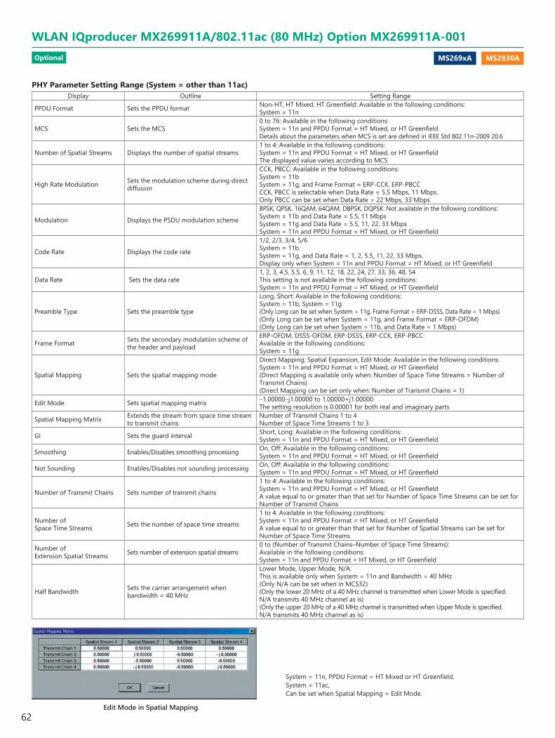
MS269xA MS2830A
Edit Mode in Spatial Mapping
System = 11n, PPDU Format = HT Mixed or HT Greenfield,System = 11ac,Can be set when Spatial Mapping = Edit Mode.
PHY Parameter Setting Range (System = other than 11ac)Display Outline Setting Range
PPDU Format Sets the PPDU format Non-HT, HT Mixed, HT Greenfield: Available in the following conditions:System = 11n
MCS Sets the MCS0 to 76: Available in the following conditions:System = 11n and PPDU Format = HT Mixed, or HT Greenfield Details about the parameters when MCS is set are defined in IEEE Std 802.11n-2009 20.6
Number of Spatial Streams Displays the number of spatial streams1 to 4: Available in the following conditions: System = 11n and PPDU Format = HT Mixed, or HT Greenfield The displayed value varies according to MCS
High Rate Modulation Sets the modulation scheme during direct diffusion
CCK, PBCC: Available in the following conditions:System = 11b System = 11g, and Frame Format = ERP-CCK, ERP-PBCC CCK, PBCC is selectable when Data Rate = 5.5 Mbps, 11 Mbps. Only PBCC can be set when Data Rate = 22 Mbps, 33 Mbps
Modulation Displays the PSDU modulation scheme
BPSK, QPSK, 16QAM, 64QAM, DBPSK, DQPSK: Not available in the following conditions:System = 11b and Data Rate = 5.5, 11 MbpsSystem = 11g and Data Rate = 5.5, 11, 22, 33 MbpsSystem = 11n and PPDU Format = HT Mixed, or HT Greenfield
Code Rate Displays the code rate
1/2, 2/3, 3/4, 5/6System = 11bSystem = 11g, and Data Rate = 1, 2, 5.5, 11, 22, 33 Mbps. Display only when System = 11n and PPDU Format = HT Mixed, or HT Greenfield
Data Rate Sets the data rate1, 2, 3, 4.5, 5.5, 6, 9, 11, 12, 18, 22, 24, 27, 33, 36, 48, 54This setting is not available in the following conditions: System = 11n and PPDU Format = HT Mixed, or HT Greenfield
Preamble Type Sets the preamble type
Long, Short: Available in the following conditions:System = 11b, System = 11g (Only Long can be set when System = 11g, Frame Format = ERP-DSSS, Data Rate = 1 Mbps)(Only Long can be set when System = 11g, and Frame Format = ERP-OFDM)(Only Long can be set when System = 11b, and Data Rate = 1 Mbps)
Frame Format Sets the secondary modulation scheme of the header and payload
ERP-OFDM, DSSS-OFDM, ERP-DSSS, ERP-CCK, ERP-PBCC: Available in the following conditions:System = 11g
Spatial Mapping Sets the spatial mapping mode
Direct Mapping, Spatial Expansion, Edit Mode: Available in the following conditions:System = 11n and PPDU Format = HT Mixed, or HT Greenfield (Direct Mapping is available only when: Number of Space Time Streams = Number of Transmit Chains) (Direct Mapping can be set only when: Number of Transmit Chains = 1)
Edit Mode Sets spatial mapping matrix –1.00000–j1.00000 to 1.00000+j1.00000 The setting resolution is 0.00001 for both real and imaginary parts
Spatial Mapping Matrix Extends the stream from space time stream to transmit chains
Number of Transmit Chains 1 to 4 Number of Space Time Streams 1 to 3
GI Sets the guard interval Short, Long: Available in the following conditions:System = 11n and PPDU Format = HT Mixed, or HT Greenfield
Smoothing Enables/Disables smoothing processing On, Off: Available in the following conditions:System = 11n and PPDU Format = HT Mixed, or HT Greenfield
Not Sounding Enables/Disables not sounding processing On, Off: Available in the following conditions:System = 11n and PPDU Format = HT Mixed, or HT Greenfield
Number of Transmit Chains Sets number of transmit chains
1 to 4: Available in the following conditions:System = 11n and PPDU Format = HT Mixed, or HT Greenfield A value equal to or greater than that set for Number of Space Time Streams can be set for Number of Transmit Chains
Number of Space Time Streams Sets the number of space time streams
1 to 4: Available in the following conditions:System = 11n and PPDU Format = HT Mixed, or HT Greenfield A value equal to or greater than that set for Number of Spatial Streams can be set for Number of Space Time Streams
Number of Extension Spatial Streams Sets number of extension spatial streams
0 to (Number of Transmit Chains–Number of Space Time Streams):Available in the following conditions:System = 11n and PPDU Format = HT Mixed, or HT Greenfield
Half Bandwidth Sets the carrier arrangement when bandwidth = 40 MHz
Lower Mode, Upper Mode, N/A:This is available only when System = 11n and Bandwidth = 40 MHz (Only N/A can be set when in MCS32)(Only the lower 20 MHz of a 40 MHz channel is transmitted when Lower Mode is specified. N/A transmits 40 MHz channel as is)(Only the upper 20 MHz of a 40 MHz channel is transmitted when Upper Mode is specified. N/A transmits 40 MHz channel as is)
WLAN IQproducer MX269911A/802.11ac (80 MHz) Option MX269911A-001Optional
62
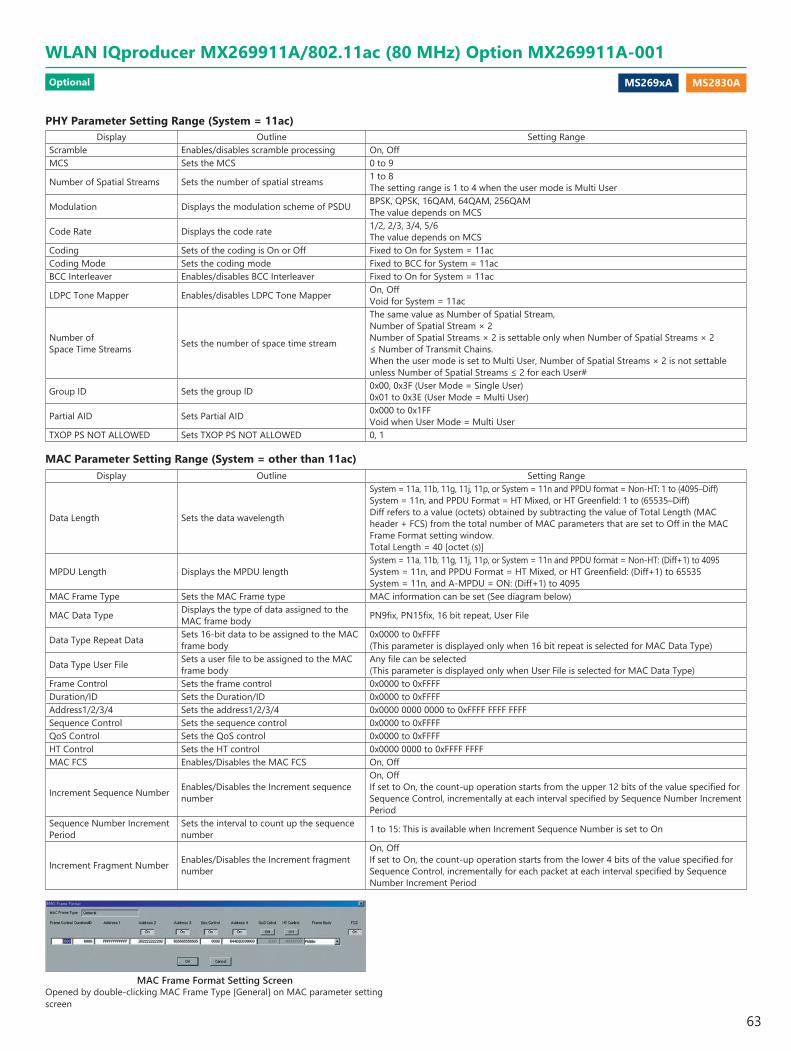
MS269xA MS2830A
MAC Frame Format Setting ScreenOpened by double-clicking MAC Frame Type [General] on MAC parameter setting screen
PHY Parameter Setting Range (System = 11ac)Display Outline Setting Range
Scramble Enables/disables scramble processing On, OffMCS Sets the MCS 0 to 9
Number of Spatial Streams Sets the number of spatial streams 1 to 8 The setting range is 1 to 4 when the user mode is Multi User
Modulation Displays the modulation scheme of PSDU BPSK, QPSK, 16QAM, 64QAM, 256QAM The value depends on MCS
Code Rate Displays the code rate 1/2, 2/3, 3/4, 5/6 The value depends on MCS
Coding Sets of the coding is On or Off Fixed to On for System = 11acCoding Mode Sets the coding mode Fixed to BCC for System = 11acBCC Interleaver Enables/disables BCC Interleaver Fixed to On for System = 11ac
LDPC Tone Mapper Enables/disables LDPC Tone Mapper On, Off Void for System = 11ac
Number of Space Time Streams Sets the number of space time stream
The same value as Number of Spatial Stream, Number of Spatial Stream × 2 Number of Spatial Streams × 2 is settable only when Number of Spatial Streams × 2 ≤ Number of Transmit Chains. When the user mode is set to Multi User, Number of Spatial Streams × 2 is not settable unless Number of Spatial Streams ≤ 2 for each User#
Group ID Sets the group ID 0x00, 0x3F (User Mode = Single User) 0x01 to 0x3E (User Mode = Multi User)
Partial AID Sets Partial AID 0x000 to 0x1FF Void when User Mode = Multi User
TXOP PS NOT ALLOWED Sets TXOP PS NOT ALLOWED 0, 1
MAC Parameter Setting Range (System = other than 11ac)Display Outline Setting Range
Data Length Sets the data wavelength
System = 11a, 11b, 11g, 11j, 11p, or System = 11n and PPDU format = Non-HT: 1 to (4095–Diff)System = 11n, and PPDU Format = HT Mixed, or HT Greenfield: 1 to (65535–Diff)Diff refers to a value (octets) obtained by subtracting the value of Total Length (MAC header + FCS) from the total number of MAC parameters that are set to Off in the MAC Frame Format setting window.Total Length = 40 [octet (s)]
MPDU Length Displays the MPDU lengthSystem = 11a, 11b, 11g, 11j, 11p, or System = 11n and PPDU format = Non-HT: (Diff+1) to 4095System = 11n, and PPDU Format = HT Mixed, or HT Greenfield: (Diff+1) to 65535 System = 11n, and A-MPDU = ON: (Diff+1) to 4095
MAC Frame Type Sets the MAC Frame type MAC information can be set (See diagram below)
MAC Data Type Displays the type of data assigned to the MAC frame body PN9fix, PN15fix, 16 bit repeat, User File
Data Type Repeat Data Sets 16-bit data to be assigned to the MAC frame body
0x0000 to 0xFFFF (This parameter is displayed only when 16 bit repeat is selected for MAC Data Type)
Data Type User File Sets a user file to be assigned to the MAC frame body
Any file can be selected (This parameter is displayed only when User File is selected for MAC Data Type)
Frame Control Sets the frame control 0x0000 to 0xFFFFDuration/ID Sets the Duration/ID 0x0000 to 0xFFFFAddress1/2/3/4 Sets the address1/2/3/4 0x0000 0000 0000 to 0xFFFF FFFF FFFFSequence Control Sets the sequence control 0x0000 to 0xFFFFQoS Control Sets the QoS control 0x0000 to 0xFFFFHT Control Sets the HT control 0x0000 0000 to 0xFFFF FFFFMAC FCS Enables/Disables the MAC FCS On, Off
Increment Sequence Number Enables/Disables the Increment sequence number
On, Off If set to On, the count-up operation starts from the upper 12 bits of the value specified for Sequence Control, incrementally at each interval specified by Sequence Number Increment Period
Sequence Number Increment Period
Sets the interval to count up the sequence number 1 to 15: This is available when Increment Sequence Number is set to On
Increment Fragment Number Enables/Disables the Increment fragment number
On, Off If set to On, the count-up operation starts from the lower 4 bits of the value specified for Sequence Control, incrementally for each packet at each interval specified by Sequence Number Increment Period
WLAN IQproducer MX269911A/802.11ac (80 MHz) Option MX269911A-001Optional
63
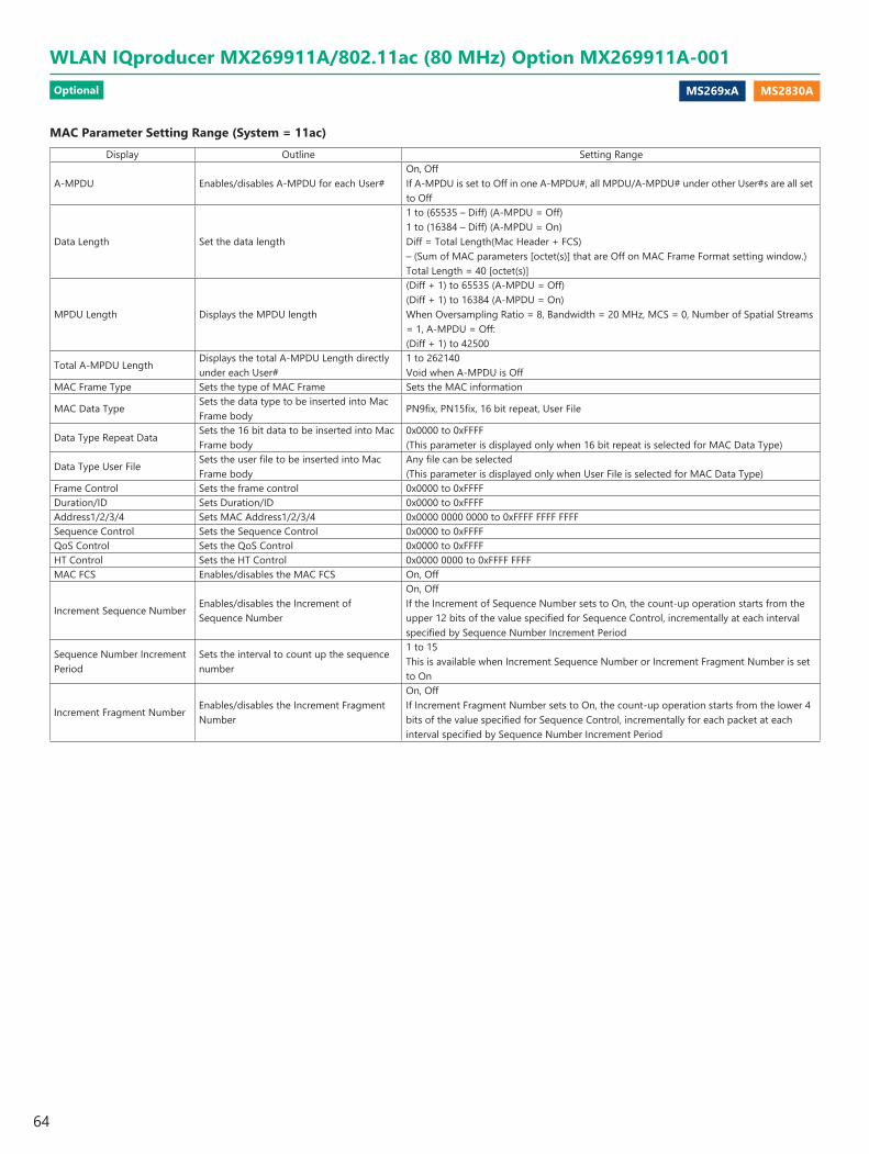
MS269xA MS2830A
MAC Parameter Setting Range (System = 11ac)Display Outline Setting Range
A-MPDU Enables/disables A-MPDU for each User#On, Off If A-MPDU is set to Off in one A-MPDU#, all MPDU/A-MPDU# under other User#s are all set to Off
Data Length Set the data length
1 to (65535 – Diff) (A-MPDU = Off) 1 to (16384 – Diff) (A-MPDU = On) Diff = Total Length(Mac Header + FCS) – (Sum of MAC parameters [octet(s)] that are Off on MAC Frame Format setting window.) Total Length = 40 [octet(s)]
MPDU Length Displays the MPDU length
(Diff + 1) to 65535 (A-MPDU = Off) (Diff + 1) to 16384 (A-MPDU = On) When Oversampling Ratio = 8, Bandwidth = 20 MHz, MCS = 0, Number of Spatial Streams = 1, A-MPDU = Off: (Diff + 1) to 42500
Total A-MPDU LengthDisplays the total A-MPDU Length directly under each User#
1 to 262140 Void when A-MPDU is Off
MAC Frame Type Sets the type of MAC Frame Sets the MAC information
MAC Data TypeSets the data type to be inserted into Mac Frame body
PN9fix, PN15fix, 16 bit repeat, User File
Data Type Repeat DataSets the 16 bit data to be inserted into Mac Frame body
0x0000 to 0xFFFF (This parameter is displayed only when 16 bit repeat is selected for MAC Data Type)
Data Type User FileSets the user file to be inserted into Mac Frame body
Any file can be selected(This parameter is displayed only when User File is selected for MAC Data Type)
Frame Control Sets the frame control 0x0000 to 0xFFFFDuration/ID Sets Duration/ID 0x0000 to 0xFFFFAddress1/2/3/4 Sets MAC Address1/2/3/4 0x0000 0000 0000 to 0xFFFF FFFF FFFFSequence Control Sets the Sequence Control 0x0000 to 0xFFFFQoS Control Sets the QoS Control 0x0000 to 0xFFFFHT Control Sets the HT Control 0x0000 0000 to 0xFFFF FFFFMAC FCS Enables/disables the MAC FCS On, Off
Increment Sequence NumberEnables/disables the Increment of Sequence Number
On, Off If the Increment of Sequence Number sets to On, the count-up operation starts from the upper 12 bits of the value specified for Sequence Control, incrementally at each interval specified by Sequence Number Increment Period
Sequence Number Increment Period
Sets the interval to count up the sequence number
1 to 15 This is available when Increment Sequence Number or Increment Fragment Number is set to On
Increment Fragment NumberEnables/disables the Increment Fragment Number
On, Off If Increment Fragment Number sets to On, the count-up operation starts from the lower 4 bits of the value specified for Sequence Control, incrementally for each packet at each interval specified by Sequence Number Increment Period
WLAN IQproducer MX269911A/802.11ac (80 MHz) Option MX269911A-001Optional
64

MS269xA MS2830A
TD-SCDMA IQproducer MX269912A is PC application software with a GUI for changing parameters and generating waveform patterns in compliance with TD-SCDMA specifications standardized by 3GPP TS 25.221, TS 25.222, TS 25.223, TS 25.105, TS 25.142 (supports TRx tests excluding performance tests).
Sub-frame Structure ScreenDisplays RU (Resource Unit) for each channel in different colors.Arranges in cells for 7 slots (for 1 Sub-frame) in RU units.
Horizontal axis: Time Slot, 7RUVertical axis: Channel Code, 16RU
TD-SCDMA IQproducer Setting ScreenSupports both uplink and downlink and settings for up to 6 carriers.
Midamble Config
Frequency Offset
Uplink/Downlink
TD-SCDMA IQproducer Setting Screen
Channel Setting(See next page.)
TD-SCDMA IQproducer MX269912AOptional
65
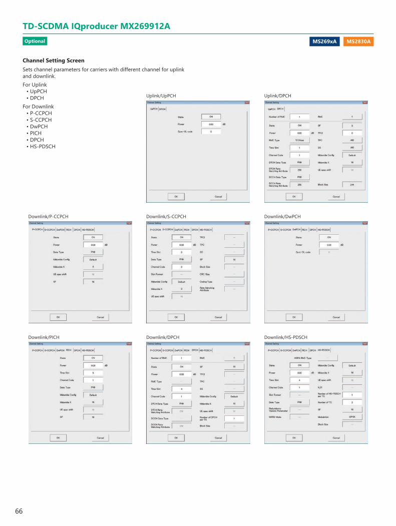
MS269xA MS2830A
Channel Setting ScreenSets channel parameters for carriers with different channel for uplink and downlink.For Uplink
• UpPCH• DPCH
For Downlink• P-CCPCH• S-CCPCH• DwPCH• PICH• DPCH• HS-PDSCH
Downlink/PICH
Downlink/P-CCPCH
Downlink/DPCH
Downlink/S-CCPCH
Uplink/UpPCH
Downlink/HS-PDSCH
Downlink/DwPCH
Uplink/DPCH
TD-SCDMA IQproducer MX269912AOptional
66

MS269xA MS2830A
Common Parameter Setting RangeDisplay Outline Setting Range
Number of sub-frames Sets the number of sub-frames <Table 1>Link Sets Downlink and Uplink signals UL, DLNumber of Carriers Sets number of carriers 1 to 6
Adjust Carrier PowerAdjusts Relative Power of each Carrier so that the maximum value of Relative Power is 0.00 dB
Adjust Code PowerAdjusts each Carrier so that the maximum value of the channel Power is 0.00 dB
Carrier Parameter Setting RangeDisplay Outline Setting Range
Frequency Offset Sets carrier frequency offset–4.0, –3.2, –2.4, –1.6, –0.8, 0, +0.8, +1.6, +2.4, +3.2, +4.0 MHzThe frequency offset range of selectable carrier varies according to the setting of Number of Carriers.
Relative Power Sets the level ratio of selected carrier 0.00 to –40.00 dB, Resolution 0.01 dB
Channel Coding Enables/disables channel codingLink = DL: OffLink = UL: OnYou cannot change the parameter of this function with this version.
Switching PointSets a Switching Point position (switching timing between DL and UL)
1 to 6 (This is set after Time Slot with the same value.)When Link is DL, a value beyond Time Slot (later in time) where Channel is already allocated cannot be set to Switching Point.When Link is UL, a value smaller than Time Slot (earlier in time) where Channel is already allocated cannot be set to Switching Point.
Scrambling Code Sets the scrambling code 0 to 127Midamble Config Displays the Midamble Config. Default, Common, UE Specification
Channel Parameter Setting RangeDisplay Outline Setting Range
When Link is DLP-CCPCHState Turns On/Off the channel On, OffPower Sets channel power 0.00 to –40.00 dB, Resolution 0.01 dBData Type Sets the data type to be mapped to channel PN9, PN15, All 0, All 1, User FileMidamble Config Displays the Midamble Config. The Midamble Config value set in Carrier Setting will be displayed.Midamble K Displays the Midamble K value 2, 4, 6, 8, 10, 12, 14, 16UE spec shift Sets the UE spec shift value 1 to Midamble KSF Displays the spreading factor Display onlyS-CCPCHState Turns On/Off the channel On, OffPower Sets channel power 0.00 to –40.00 dB, Resolution 0.01 dBTime Slot Sets the position of Time Slot to be allocated 0, 2 to 6Data Type Sets the data type to be mapped to channel PN9, PN15, All 0, All 1, User FileChannel Code Sets the Channelization Code 1 to 15Midamble Config Displays the Midamble Config. The Midamble Config value set in Carrier Setting will be displayed.Midamble K Sets the Midamble K value 2, 4, 6, 8, 10, 12, 14, 16UE spec shift Sets the UE spec shift value 1 to Midamble KSF Displays the spreading factor Display onlyDwPCHState Turns On/Off the channel On, OffPower Sets channel power 0.00 to –40.00 dB, Resolution 0.01 dBSync-DL code Sets the Sync-DL code It is auto-calculated from the Scrambling Code of Carrier Setting.
Table 1
MS269x
Memory 256 Msamples —1 10485 —2 5242 —
3 to 6 2621 —
MS2830
Memory Option Without Option 27 (Memory 256 Msamples) With Option 27 (Memory 256 Msamples)1 2621 104852 1310 5242
3 to 6 655 2621
TD-SCDMA IQproducer MX269912AOptional
67
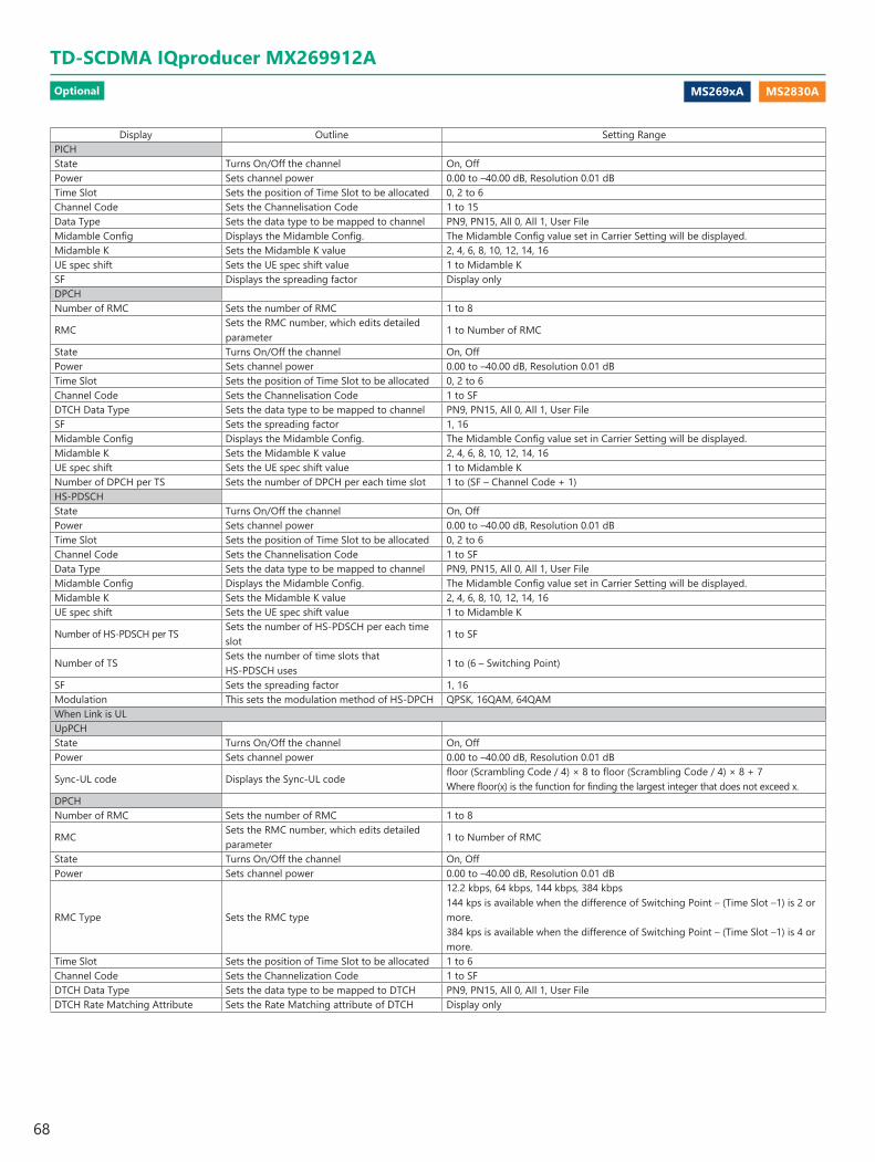
MS269xA MS2830A
Display Outline Setting RangePICHState Turns On/Off the channel On, OffPower Sets channel power 0.00 to –40.00 dB, Resolution 0.01 dBTime Slot Sets the position of Time Slot to be allocated 0, 2 to 6Channel Code Sets the Channelisation Code 1 to 15Data Type Sets the data type to be mapped to channel PN9, PN15, All 0, All 1, User FileMidamble Config Displays the Midamble Config. The Midamble Config value set in Carrier Setting will be displayed.Midamble K Sets the Midamble K value 2, 4, 6, 8, 10, 12, 14, 16UE spec shift Sets the UE spec shift value 1 to Midamble KSF Displays the spreading factor Display onlyDPCHNumber of RMC Sets the number of RMC 1 to 8
RMCSets the RMC number, which edits detailed parameter
1 to Number of RMC
State Turns On/Off the channel On, OffPower Sets channel power 0.00 to –40.00 dB, Resolution 0.01 dBTime Slot Sets the position of Time Slot to be allocated 0, 2 to 6Channel Code Sets the Channelisation Code 1 to SFDTCH Data Type Sets the data type to be mapped to channel PN9, PN15, All 0, All 1, User FileSF Sets the spreading factor 1, 16Midamble Config Displays the Midamble Config. The Midamble Config value set in Carrier Setting will be displayed.Midamble K Sets the Midamble K value 2, 4, 6, 8, 10, 12, 14, 16UE spec shift Sets the UE spec shift value 1 to Midamble KNumber of DPCH per TS Sets the number of DPCH per each time slot 1 to (SF – Channel Code + 1)HS-PDSCHState Turns On/Off the channel On, OffPower Sets channel power 0.00 to –40.00 dB, Resolution 0.01 dBTime Slot Sets the position of Time Slot to be allocated 0, 2 to 6Channel Code Sets the Channelisation Code 1 to SFData Type Sets the data type to be mapped to channel PN9, PN15, All 0, All 1, User FileMidamble Config Displays the Midamble Config. The Midamble Config value set in Carrier Setting will be displayed.Midamble K Sets the Midamble K value 2, 4, 6, 8, 10, 12, 14, 16UE spec shift Sets the UE spec shift value 1 to Midamble K
Number of HS-PDSCH per TSSets the number of HS-PDSCH per each time slot
1 to SF
Number of TSSets the number of time slots that HS-PDSCH uses
1 to (6 – Switching Point)
SF Sets the spreading factor 1, 16Modulation This sets the modulation method of HS-DPCH QPSK, 16QAM, 64QAMWhen Link is ULUpPCHState Turns On/Off the channel On, OffPower Sets channel power 0.00 to –40.00 dB, Resolution 0.01 dB
Sync-UL code Displays the Sync-UL codefloor (Scrambling Code / 4) × 8 to floor (Scrambling Code / 4) × 8 + 7Where floor(x) is the function for finding the largest integer that does not exceed x.
DPCHNumber of RMC Sets the number of RMC 1 to 8
RMCSets the RMC number, which edits detailed parameter
1 to Number of RMC
State Turns On/Off the channel On, OffPower Sets channel power 0.00 to –40.00 dB, Resolution 0.01 dB
RMC Type Sets the RMC type
12.2 kbps, 64 kbps, 144 kbps, 384 kbps144 kps is available when the difference of Switching Point – (Time Slot –1) is 2 or more. 384 kps is available when the difference of Switching Point – (Time Slot –1) is 4 or more.
Time Slot Sets the position of Time Slot to be allocated 1 to 6Channel Code Sets the Channelization Code 1 to SFDTCH Data Type Sets the data type to be mapped to DTCH PN9, PN15, All 0, All 1, User FileDTCH Rate Matching Attribute Sets the Rate Matching attribute of DTCH Display only
TD-SCDMA IQproducer MX269912AOptional
68
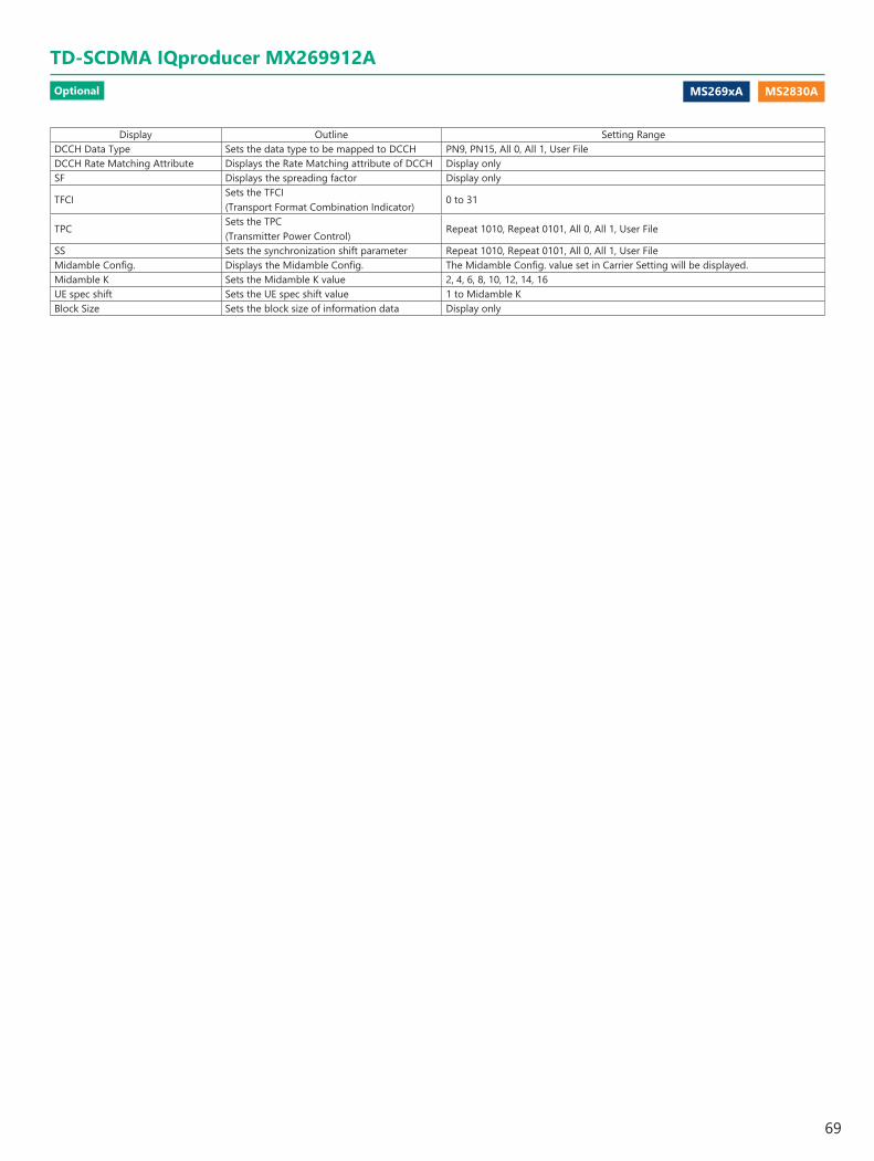
MS269xA MS2830A
Display Outline Setting RangeDCCH Data Type Sets the data type to be mapped to DCCH PN9, PN15, All 0, All 1, User FileDCCH Rate Matching Attribute Displays the Rate Matching attribute of DCCH Display onlySF Displays the spreading factor Display only
TFCISets the TFCI (Transport Format Combination Indicator)
0 to 31
TPCSets the TPC (Transmitter Power Control)
Repeat 1010, Repeat 0101, All 0, All 1, User File
SS Sets the synchronization shift parameter Repeat 1010, Repeat 0101, All 0, All 1, User FileMidamble Config. Displays the Midamble Config. The Midamble Config. value set in Carrier Setting will be displayed.Midamble K Sets the Midamble K value 2, 4, 6, 8, 10, 12, 14, 16UE spec shift Sets the UE spec shift value 1 to Midamble KBlock Size Sets the block size of information data Display only
TD-SCDMA IQproducer MX269912AOptional
69
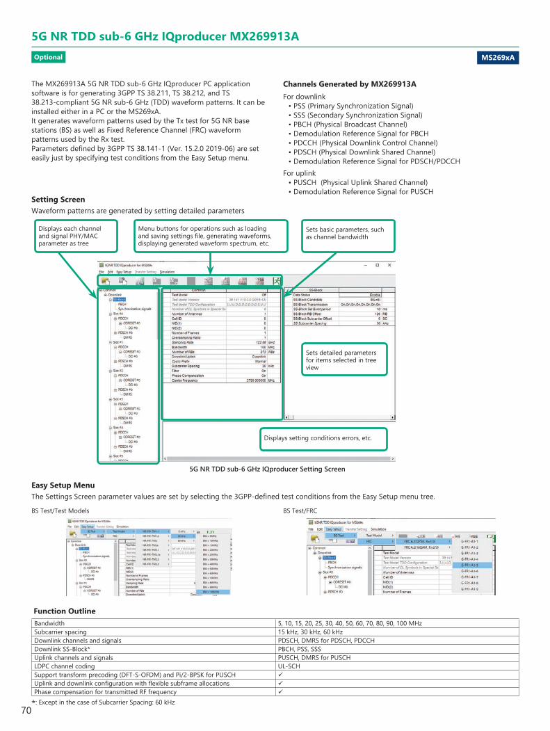
MS269xA
5G NR TDD sub-6 GHz IQproducer MX269913AOptional
The MX269913A 5G NR TDD sub-6 GHz IQproducer PC application software is for generating 3GPP TS 38.211, TS 38.212, and TS 38.213-compliant 5G NR sub-6 GHz (TDD) waveform patterns. It can be installed either in a PC or the MS269xA. It generates waveform patterns used by the Tx test for 5G NR base stations (BS) as well as Fixed Reference Channel (FRC) waveform patterns used by the Rx test. Parameters defined by 3GPP TS 38.141-1 (Ver. 15.2.0 2019-06) are set easily just by specifying test conditions from the Easy Setup menu.
Channels Generated by MX269913AFor downlink
• PSS (Primary Synchronization Signal)• SSS (Secondary Synchronization Signal)• PBCH (Physical Broadcast Channel) • Demodulation Reference Signal for PBCH• PDCCH (Physical Downlink Control Channel) • PDSCH (Physical Downlink Shared Channel) • Demodulation Reference Signal for PDSCH/PDCCH
For uplink• PUSCH (Physical Uplink Shared Channel) • Demodulation Reference Signal for PUSCH
Displays setting conditions errors, etc.
Sets detailed parameters for items selected in tree view
Displays each channel and signal PHY/MAC parameter as tree
Menu buttons for operations such as loading and saving settings file, generating waveforms, displaying generated waveform spectrum, etc.
Sets basic parameters, such as channel bandwidth
Function OutlineBandwidth 5, 10, 15, 20, 25, 30, 40, 50, 60, 70, 80, 90, 100 MHzSubcarrier spacing 15 kHz, 30 kHz, 60 kHzDownlink channels and signals PDSCH, DMRS for PDSCH, PDCCHDownlink SS-Block* PBCH, PSS, SSSUplink channels and signals PUSCH, DMRS for PUSCHLDPC channel coding UL-SCHSupport transform precoding (DFT-S-OFDM) and Pi/2-BPSK for PUSCH Uplink and downlink configuration with flexible subframe allocations Phase compensation for transmitted RF frequency
*: Except in the case of Subcarrier Spacing: 60 kHz
Setting ScreenWaveform patterns are generated by setting detailed parameters
5G NR TDD sub-6 GHz IQproducer Setting Screen
Easy Setup Menu The Settings Screen parameter values are set by selecting the 3GPP-defined test conditions from the Easy Setup menu tree.
BS Test/Test Models BS Test/FRC
70
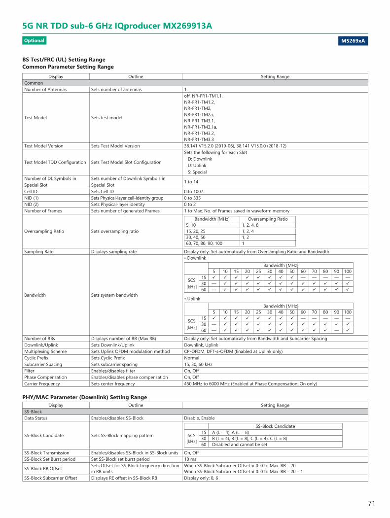
MS269xA
5G NR TDD sub-6 GHz IQproducer MX269913AOptional
BS Test/FRC (UL) Setting Range Common Parameter Setting Range
Display Outline Setting RangeCommonNumber of Antennas Sets number of antennas 1
Test Model Sets test model
off, NR-FR1-TM1.1,NR-FR1-TM1.2,NR-FR1-TM2,NR-FR1-TM2a,NR-FR1-TM3.1,NR-FR1-TM3.1a,NR-FR1-TM3.2,NR-FR1-TM3.3
Test Model Version Sets Test Model Version 38.141 V15.2.0 (2019-06), 38.141 V15.0.0 (2018-12)
Test Model TDD Configuration Sets Test Model Slot Configuration
Sets the following for each SlotD: DownlinkU: UplinkS: Special
Number of DL Symbols in Special Slot
Sets number of Downlink Symbols in Special Slot
1 to 14
Cell ID Sets Cell ID 0 to 1007NID (1) Sets Physical-layer cell-identity group 0 to 335NID (2) Sets Physical-layer identity 0 to 2Number of Frames Sets number of generated Frames 1 to Max. No. of Frames saved in waveform memory
Oversampling Ratio Sets oversampling ratio
Bandwidth [MHz] Oversampling Ratio5, 10 1, 2, 4, 815, 20, 25 1, 2, 430, 40, 50 1, 260, 70, 80, 90, 100 1
Sampling Rate Displays sampling rate Display only: Set automatically from Oversampling Ratio and Bandwidth
Bandwidth Sets system bandwidth
• DownlinkBandwidth [MHz]
5 10 15 20 25 30 40 50 60 70 80 90 100
SCS [kHz]
15 — — — — —30 — 60 —
• UplinkBandwidth [MHz]
5 10 15 20 25 30 40 50 60 70 80 90 100
SCS [kHz]
15 — — — — —30 — 60 — —
Number of RBs Displays number of RB (Max RB) Display only: Set automatically from Bandwidth and Subcarrier SpacingDownlink/Uplink Sets Downlink/Uplink Downlink, UplinkMultiplexing Scheme Sets Uplink OFDM modulation method CP-OFDM, DFT-s-OFDM (Enabled at Uplink only) Cyclic Prefix Sets Cyclic Prefix NormalSubcarrier Spacing Sets subcarrier spacing 15, 30, 60 kHzFilter Enables/disables filter On, OffPhase Compensation Enables/disables phase compensation On, OffCarrier Frequency Sets center frequency 450 MHz to 6000 MHz (Enabled at Phase Compensation: On only)
PHY/MAC Parameter (Downlink) Setting RangeDisplay Outline Setting Range
SS-BlockData Status Enables/disables SS-Block Disable, Enable
SS-Block Candidate Sets SS-Block mapping pattern
SS-Block Candidate
SCS [kHz]
15 A (L = 4), A (L = 8)30 B (L = 4), B (L = 8), C (L = 4), C (L = 8)60 Disabled and cannot be set
SS-Block Transmission Enables/disables SS-Block in SS-Block units On, OffSS-Block Set Burst period Set SS-Block set burst period 10 ms
SS-Block RB Offset Sets Offset for SS-Block frequency direction in RB units
When SS-Block Subcarrier Offset = 0: 0 to Max. RB – 20When SS-Block Subcarrier Offset ≠ 0: 0 to Max. RB – 20 – 1
SS-Block Subcarrier Offset Displays RE offset in SS-Block RB Display only: 0, 6
71
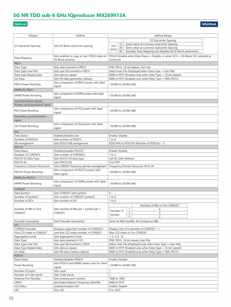
MS269xA
5G NR TDD sub-6 GHz IQproducer MX269913AOptional
Display Outline Setting Range
SS Subcarrier Spacing Sets SS-Block subcarrier spacing
SS Subcarrier Spacing
SCS [kHz]
15 Same value as Common Subcarrier Spacing30 Same value as Common Subcarrier Spacing60 Excludes Data Mapping and disables all SS-Block parameters
Data Mapping Sets whether to map or null PDSCH data at SS-Block position
PDSCH (Enable when Data Status = Disable, or when SCS = /SS-Block SCS selected at Common)
PBCHData Type Sets data inserted in PBCH PN9, PN15, 16-bit repeat, User FileData Type User File Sets user file inserted in PBCH Select User File (Displayed when Data Type = User File) Data Type Repeat Data Sets data to repeat 0000 to FFFF (Enabled only when Data Type = 16-bit repeat) Init Data Sets PN data generation default 0000 to FFFF (Enabled only when Data Type = PN9, PN15)
PBCH Power Boosting Sets comparison of PBCH power with ideal signal –20.000 to 20.000 [dB]
DMRS for PBCH
DMRS Power Boosting Sets comparison of DMRS power with ideal signal –20.000 to 20.000 [dB]
Synchronization signalsPrimary synchronization signal
PSS Power BoostingSets comparison of PSS power with ideal signal
–20.000 to 20.000 [dB]
Secondary synchronization signal
SSS Power BoostingSets comparison of SSS power with ideal signal
–20.000 to 20.000 [dB]
SlotData Status Enables/disables slot Enable, DisableNumber of PDSCHs Sets number of PDSCH 1 to 8RB arrangement Sets PDSCH RB arrangement PDSCH#0 to PDSCH# (Number of PDSCHs – 1)PDCCHData Status Enables/disables PDCCH Enable, DisableNumber of CORESETs Sets number of CORESETs 1 to 3PDCCH ID Data Type Sets PDCCH ID data type Cell ID, User DefinedPDCCH ID Sets PDCCH ID 0 to FFFFFrequency Domain Resources Sets CORESET frequency domain arrangement Frequency Domain Resource #0 to 44
PDCCH Power BoostingSets comparison of PDCCH power with ideal signal
–20.000 to 20.000 [dB]
DMRS for PDCCH
DMRS Power BoostingSets comparison of DMRS power with ideal signal
–20.000 to 20.000 [dB]
CORESETStart Symbol Sets CORESET start symbol 0Number of Symbols Sets number of CORESET symbols 1 to 3Number of DCIs Sets number of DCI 1 to 8
Number of RBs In One CORESET
Sets number of RBs per 1 symbol per 1 CORESET
Number of RBs In One CORESET
Number of Symbol
1 62 33 2
Precoder Granularity Sets Precoder Granularity Same As REG-bundle, All Contiguous RBsDCICORESET Number Displays supported number of CORESETs Display only: 0 to Number of CORESET – 1First CCE Index In CORESET Sets first CCE Index number in CORESET Max CCE Index in 0 to CORESETAggregation Level Sets Aggregation Level 1, 2, 4, 8, 16Data Type Sets data inserted in DCI PN9, PN15, 16 bit repeat, User FileData Type User File Sets user file inserted in PBCH Select User File (Displayed only when Data Type = User File) Data Type Repeat Data Sets data to repeat 0000 to FFFF (Enabled only when Data Type = 16-bit repeat) Init Data Sets PN data creation default 0000 to FFFF (Enabled only when Data Type = PN9, PN15) PDSCHData Status Enables/disables PDSCH Enable, Disable
Power BoostingSets PDSCH and DMRS power ratio for ideal signal
–20.000 to 20.000 [dB]
Number of Layers Sets Layer 1Number of Code words Sets Code words 1Antenna Port Number Sets antenna port number 1000 to 1005nRNTI Sets Radio Network Temporary Identifier 0000 to FFFFnID Status Enables/disables nID Enable, DisablenID Sets nID 0 to 1023
72

MS269xA
5G NR TDD sub-6 GHz IQproducer MX269913AOptional
Display Outline Setting RangeModulation Scheme Sets modulation method QPSK, 16QAM, 64QAM, 256QAMPDSCH mapping type Sets PDSCH mapping type A, B
Symbol Start Sets PDSCH start symbol
PDSCH mapping type DMRS TypeA Position Symbol Start
A 3 32 0, 1, 2
B — 0 to 12
Symbol Length Sets PDSCH symbol lengthPDSCH mapping type Symbol Length
A 3 to 14B 2, 4, 7
Symbol End Displays PDSC end symbol Display only: Set automatically using Symbol Length and Symbol StartData Type Sets data inserted in PDSCH PN9, PN15, 16-bit repeat, User FileData Type User File Sets user file inserted in PDSCH Select user file (Displayed only when Data Type = User File) Data Type Repeat Data Sets data to repeat 0000 to FFFF (Displayed only when Data Type = 16-bit repeat) Init Data Sets default value for PN data generation 0000 to FFFF (Enabled when Data Type = PN9, PN15) DMRSnSCID Sets nSCID 0, 1DMRS nSCID Data Type Sets DMRS nSCID data type Cell ID, User DefinedDMRS nSCID Sets DMRS nSCID 0 to 65535DMRS Length Sets DMRS symbol 1
DMRS Additional Position Sets DMRS additional position number
PDSCH mapping typeSymbol End – Symbol Start
DMRS Additional Position
A ≥3 0, 1, 2, 3B 2, 4, 6 0, 1Other than above No setting
DMRS Configuration Type Sets DMRS configuration type 1, 2
Number of DMRS CDM groups without Data
Sets whether to insert data between DMRS or not
DMRS Configuration Type
Antenna Port NumberNumber of DMRS CDM groups without Data
1 1000 1, 21 1001 1, 21 1002 21 1003 22 1000 1, 2, 32 1001 1, 2, 32 1002 2, 32 1003 2, 32 1004 32 1005 3
DMRS TypeA Position Sets DMRS l0 position 2, 3 (Displayed at PDSCH Mapping Type A)
DMRS Power BoostingSets comparison of DMRS power with ideal signal
–20.000 to 20.000 [dB]
PHY/MAC Parameter (Uplink) Setting RangeDisplay Outline Setting Range
SlotData Status Enables/disables slot Enable, DisableNumber of PUSCHs Sets number of PUSCHs 1 to 8PUSCHData Status Enables/disables PUSCH Enable, Disable
Power BoostingSets PUSCH and DMRS power ratio for ideal signal
–20.000 to 20.000 [dB]
Number of Layers Sets layer 1Number of Code words Sets Code Words 1
Antenna Port Number Sets antenna port numberDMRS Configuration Type Antenna Port NumberType1 0 to 3Type2 0 to 5
nRNTI Sets Radio Network Temporary Identifier 0000 to FFFFnID Status Enables/disables nID Enable, DisablenID Sets nID 0 to 1023Modulation Scheme Sets modulation type QPSK, 16QAM, 64QAM, 256QAM, PI/2-BPSKPUSCH mapping type Sets PUSCH mapping type A, BRB Start Sets PUSCH start RB 0 to Max. RB - 1Number of RBs Sets number of RBs from start RB RB Start to Max. RB - 1RB End Displays PUSCH end RB Display only: Set automatically using Number of RB and RB Start
73
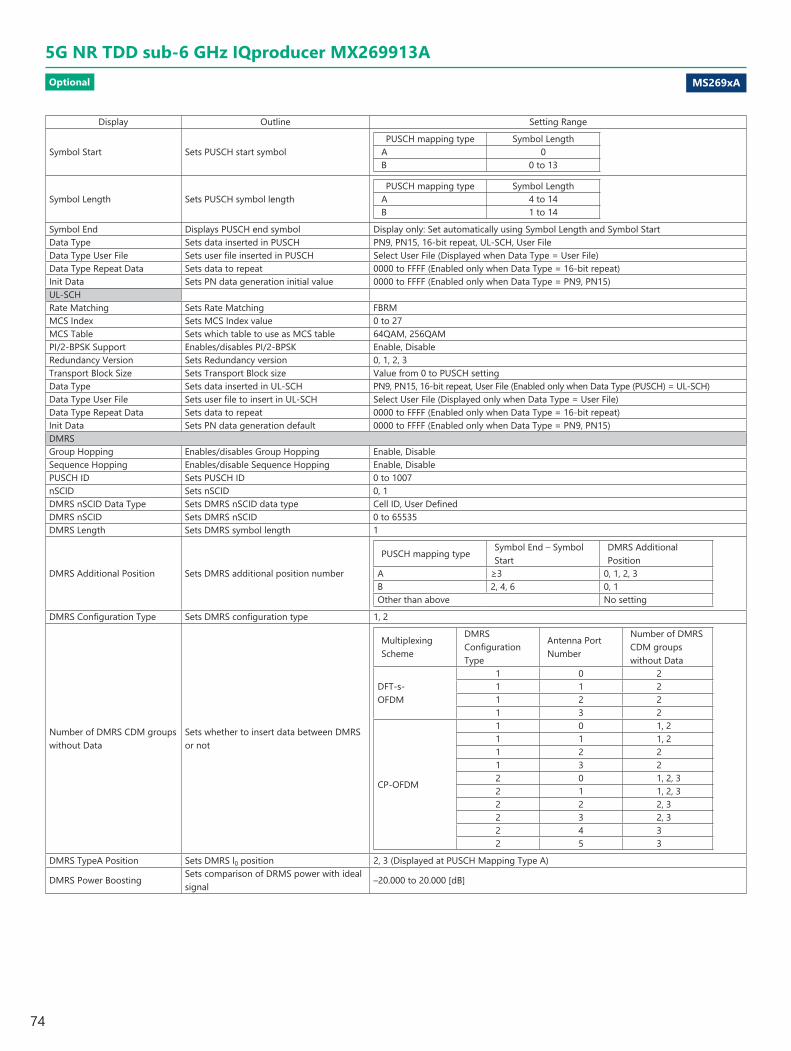
MS269xA
5G NR TDD sub-6 GHz IQproducer MX269913AOptional
Display Outline Setting Range
Symbol Start Sets PUSCH start symbolPUSCH mapping type Symbol Length
A 0B 0 to 13
Symbol Length Sets PUSCH symbol lengthPUSCH mapping type Symbol Length
A 4 to 14B 1 to 14
Symbol End Displays PUSCH end symbol Display only: Set automatically using Symbol Length and Symbol Start Data Type Sets data inserted in PUSCH PN9, PN15, 16-bit repeat, UL-SCH, User FileData Type User File Sets user file inserted in PUSCH Select User File (Displayed when Data Type = User File) Data Type Repeat Data Sets data to repeat 0000 to FFFF (Enabled only when Data Type = 16-bit repeat) Init Data Sets PN data generation initial value 0000 to FFFF (Enabled only when Data Type = PN9, PN15) UL-SCHRate Matching Sets Rate Matching FBRMMCS Index Sets MCS Index value 0 to 27MCS Table Sets which table to use as MCS table 64QAM, 256QAMPI/2-BPSK Support Enables/disables PI/2-BPSK Enable, DisableRedundancy Version Sets Redundancy version 0, 1, 2, 3Transport Block Size Sets Transport Block size Value from 0 to PUSCH settingData Type Sets data inserted in UL-SCH PN9, PN15, 16-bit repeat, User File (Enabled only when Data Type (PUSCH) = UL-SCH) Data Type User File Sets user file to insert in UL-SCH Select User File (Displayed only when Data Type = User File) Data Type Repeat Data Sets data to repeat 0000 to FFFF (Enabled only when Data Type = 16-bit repeat) Init Data Sets PN data generation default 0000 to FFFF (Enabled only when Data Type = PN9, PN15) DMRSGroup Hopping Enables/disables Group Hopping Enable, DisableSequence Hopping Enables/disable Sequence Hopping Enable, DisablePUSCH ID Sets PUSCH ID 0 to 1007nSCID Sets nSCID 0, 1DMRS nSCID Data Type Sets DMRS nSCID data type Cell ID, User DefinedDMRS nSCID Sets DMRS nSCID 0 to 65535DMRS Length Sets DMRS symbol length 1
DMRS Additional Position Sets DMRS additional position number
PUSCH mapping typeSymbol End – Symbol Start
DMRS Additional Position
A ≥3 0, 1, 2, 3B 2, 4, 6 0, 1Other than above No setting
DMRS Configuration Type Sets DMRS configuration type 1, 2
Number of DMRS CDM groups without Data
Sets whether to insert data between DMRS or not
Multiplexing Scheme
DMRS Configuration Type
Antenna Port Number
Number of DMRS CDM groups without Data
DFT-s-OFDM
1 0 21 1 21 2 21 3 2
CP-OFDM
1 0 1, 21 1 1, 21 2 21 3 22 0 1, 2, 32 1 1, 2, 32 2 2, 32 3 2, 32 4 32 5 3
DMRS TypeA Position Sets DMRS l0 position 2, 3 (Displayed at PUSCH Mapping Type A)
DMRS Power BoostingSets comparison of DRMS power with ideal signal
–20.000 to 20.000 [dB]
74

MS269xA
5G NR FDD sub-6 GHz IQproducer MX269914AOptional
5G NR FDD sub-6 GHz IQproducer MX269914A PC application software is for generating 3GPP TS 38.211, TS 38.212, and TS 38.213-compliant 5G NR sub-6 GHz (FDD) waveform patterns. It can be installed either in a PC or the MS269xA.It generates Test Model waveform patterns used by the Tx test for 5G NR base stations (BS) as well as Fixed Reference Channel (FRC) waveform patterns used by the Rx test.Parameters defined by 3GPP TS 38.141-1 (Ver. 15.2.0 2019-06) are set easily just by specifying test conditions from the Easy Setup menu.
Channels Generated by MX269914AFor downlink
• PSS (Primary Synchronization Signal)• SSS (Secondary Synchronization Signal)• PBCH (Physical Broadcast Channel) • Demodulation Reference Signal for PBCH• PDCCH (Physical Downlink Control Channel) • PDSCH (Physical Downlink Shared Channel) • Demodulation Reference Signal for PDSCH/PDCCH
For uplink• PUSCH (Physical Uplink Shared Channel) • Demodulation Reference Signal for PUSCH
Displays setting conditions errors, etc.
Sets detailed parameters for items selected in tree view
Function OutlineBandwidth 5, 10, 15, 20, 25, 30, 40, 50, 60, 70, 80, 90, 100 MHzSubcarrier spacing 15 kHz, 30 kHz, 60 kHzDownlink channels and signals PDSCH, DMRS for PDSCH, PDCCHDownlink SS-Block* PBCH, PSS, SSSUplink channels and signals PUSCH, DMRS for PUSCHLDPC channel coding UL-SCHSupport transform precoding (DFT-S-OFDM) and Pi/2-BPSK for PUSCH Uplink and downlink configuration with flexible subframe allocations Phase compensation for transmitted RF frequency
*: Except in the case of Subcarrier Spacing: 60 kHz
Setting ScreenWaveform patterns are generated by setting detailed parameters
5G NR FDD sub-6 GHz IQproducer Setting Screen
Easy Setup Menu The Settings Screen parameter values are set by selecting the 3GPP-defined test conditions from the Easy Setup menu tree.
BS Test/Test Models BS Test/FRC
Displays each channel and signal PHY/MAC parameter as tree
Menu buttons for operations such as loading and saving settings file, generating waveforms, displaying generated waveform spectrum, etc.
Sets basic parameters, such as channel bandwidth
75

MS269xA
5G NR FDD sub-6 GHz IQproducer MX269914AOptional
BS Test/FRC (UL) Setting Range Common Parameter Setting Range
Display Outline Setting RangeCommonNumber of Antennas Sets number of antennas 1
Test Model Sets test model
off, NR-FR1-TM1.1,NR-FR1-TM1.2,NR-FR1-TM2,NR-FR1-TM2a,NR-FR1-TM3.1,NR-FR1-TM3.1a,NR-FR1-TM3.2,NR-FR1-TM3.3
Test Model Version Sets Test Model Version 38.141 V15.2.0 (2019-06)Number of Antennas Sets Number of Antennas 1 Cell ID Sets Cell ID 0 to 1007NID (1) Sets Physical-layer cell-identity group 0 to 335NID (2) Sets Physical-layer identity 0 to 2Number of Frames Sets number of generated Frames 1 to Max. No. of Frames saved in waveform memory
Oversampling Ratio Sets oversampling ratio
Bandwidth [MHz] Oversampling Ratio5, 10 1, 2, 4, 815, 20, 25 1, 2, 430, 40, 50 1, 260, 70, 80, 90, 100 1
Sampling Rate Displays sampling rate Display only: Set automatically from Oversampling Ratio and Bandwidth
Bandwidth Sets system bandwidth
Bandwidth [MHz]5 10 15 20 25 30 40 50 60 70 80 90 100
SCS [kHz]
15 — — — — —30 60 —
Number of RBs Displays number of RB (Max RB) Display only: Set automatically from Bandwidth and Subcarrier SpacingDownlink/Uplink Sets Downlink/Uplink Downlink, UplinkMultiplexing Scheme Sets Uplink OFDM modulation method CP-OFDM, DFT-s-OFDM (Enabled at Uplink only) Cyclic Prefix Sets Cyclic Prefix NormalSubcarrier Spacing Sets subcarrier spacing 15, 30, 60 kHzFilter Enables/disables filter On, OffPhase Compensation Enables/disables phase compensation On, OffCarrier Frequency Sets center frequency 450 MHz to 6000 MHz (Enabled at Phase Compensation: On only)
PHY/MAC Parameter (Downlink) Setting RangeDisplay Outline Setting Range
SS-BlockData Status Enables/disables SS-Block Disable, Enable
SS-Block Candidate Sets SS-Block mapping pattern
SS-Block Candidate
SCS [kHz]
15 A (L = 4), A (L = 8)30 B (L = 4), B (L = 8), C (L = 4), C (L = 8)60 Disabled and cannot be set
SS-Block TransmissionEnables/disables SS-Block in SS-Block units
On, Off
SS-Block Set Burst period Set SS-Block set burst period 10 ms
SS-Block RB OffsetSets Offset for SS-Block frequency direction in RB units
When SS-Block Subcarrier Offset = 0: 0 to Max RB – 20When SS-Block Subcarrier Offset ≠ 0: 0 to Max RB – 20 – 1
SS-Block Subcarrier Offset Sets REW offset in SS-Block RB 0 to 11
SS Subcarrier Spacing Sets SS-Block subcarrier spacing
SS Subcarrier Spacing
SCS [kHz]
15 Same value as Common Subcarrier Spacing30 Same value as Common Subcarrier Spacing60 Excludes Data Mapping and disables all SS-Block parameters
Data MappingSets whether to map or null PDSCH data at SS-Block position
PDSCH (Enable when Data Status = Disable, or when SCS = /SS-Block SCS selected at Common)
PBCHData Type Sets data inserted in PBCH PN9, PN15, 16-bit repeat, User FileData Type User File Sets user file inserted in PBCH Select User File (Displayed when Data Type = User File) Data Type Repeat Data Sets data to repeat 0000 to FFFF (Enabled only when Data Type = 16-bit repeat) Init Data Sets PN data generation default 0000 to FFFF (Enabled only when Data Type = PN9, PN15)
PBCH Power BoostingSets comparison of PBCH power with ideal signal
–20.000 to 20.000 [dB]
76

MS269xA
5G NR FDD sub-6 GHz IQproducer MX269914AOptional
Display Outline Setting RangeDMRS for PBCH
DMRS Power BoostingSets comparison of DMRS power with ideal signal
–20.000 to 20.000 [dB]
Synchronization signalsPrimary synchronization signal
PSS Power BoostingSets comparison of PSS power with ideal signal
–20.000 to 20.000 [dB]
Secondary synchronization signal
SSS Power BoostingSets comparison of SSS power with ideal signal
–20.000 to 20.000 [dB]
SlotData Status Enables/disables slot Enable, DisableNumber of PDSCHs Sets number of PDSCH 1 to 8RB arrangement Sets PDSCH RB arrangement PDSCH#0 to PDSCH# (Number of PDSCHs – 1)PDCCHData Status Enables/disables PDCCH Enable, DisableNumber of CORESETs Sets number of CORESETs 1 to 3PDCCH ID Data Type Sets PDCCH ID data type Cell ID, User DefinedPDCCH ID Sets PDCCH ID 0 to FFFF
Frequency Domain ResourcesSets CORESET frequency domain arrangement
Frequency Domain Resource #0 to 44
PDCCH Power BoostingSets comparison of PDCCH power with ideal signal
–20.000 to 20.000 [dB]
DMRS for PDCCH
DMRS Power BoostingSets comparison of DMRS power with ideal signal
–20.000 to 20.000 [dB]
CORESETStart Symbol Sets CORESET start symbol 0Number of Symbols Sets number of CORESET symbols 1 to 3Number of DCIs Sets number of DCI 1 to 8
Number of RBs In One CORESET
Sets number of RBs per 1 symbol per 1 CORESET
Number of RBs In One CORESET
Number of Symbol
1 62 33 2
Precoder Granularity Sets Precoder Granularity Same as REG-bundle, All Contiguous RBsDCICORESET Number Displays supported number of CORESETs Display only: 0 to Number of CORESET – 1First CCE Index In CORESET Sets first CCE Index number in CORESET Max CCE Index in 0 to CORESETAggregation Level Sets Aggregation Level 1, 2, 4, 8, 16Data Type Sets data inserted in DCI PN9, PN15, 16 bit repeat, User FileData Type User File Sets user file inserted in PBCH Select User File (Displayed only when Data Type = User File) Data Type Repeat Data Sets data to repeat 0000 to FFFF (Enabled only when Data Type = 16-bit repeat) Init Data Sets PN data creation default 0000 to FFFF (Enabled only when Data Type = PN9, PN15) PDSCHData Status Enables/disables PDSCH Enable, Disable
Power BoostingSets PDSCH and DMRS power ratio for ideal signal
–20.000 to 20.000 [dB]
Number of Layers Sets Layer 1Number of Code words Sets Code words 1Antenna Port Number Sets antenna port number 1000 to 1005nRNTI Sets Radio Network Temporary Identifier 0000 to FFFFnID Status Enables/disables nID Enable, DisablenID Sets nID 0 to 1023Modulation Scheme Sets modulation method QPSK, 16QAM, 64QAM, 256QAMPDSCH mapping type Sets PDSCH mapping type A, B
Symbol Start Sets PDSCH start symbol
PDSCH mapping type DMRS TypeA Position Symbol Start
A 3 32 0, 1, 2
B — 0 to 12
Symbol Length Sets PDSCH symbol lengthPDSCH mapping type Symbol Length
A 3 to 14B 2, 4, 7
Symbol End Displays PDSC end symbol Display only: Set automatically using Symbol Length and Symbol StartData Type Sets data inserted in PDSCH PN9, PN15, 16-bit repeat, User File
77

MS269xA
5G NR FDD sub-6 GHz IQproducer MX269914AOptional
Display Outline Setting RangeData Type User File Sets user file inserted in PDSCH Select user file (Displayed only when Data Type = User File) Data Type Repeat Data Sets data to repeat 0000 to FFFF (Displayed only when Data Type = 16-bit repeat) Init Data Sets default value for PN data generation 0000 to FFFF (Enabled when Data Type = PN9, PN15) DMRSnSCID Sets nSCID 0, 1DMRS nSCID Data Type Sets DMRS nSCID data type Cell ID, User DefinedDMRS nSCID Sets DMRS nSCID 0 to 65535DMRS Length Sets DMRS symbol 1
DMRS Additional Position Sets DMRS additional position number
PDSCH mapping type Symbol End – Symbol Start DMRS Additional PositionA ≥3 0, 1, 2, 3B 2, 4, 6 0, 1Other than above No setting
DMRS Configuration Type Sets DMRS configuration type 1, 2
Number of DMRS CDM groups without Data
Sets whether to insert data between DMRS or not
DMRS Configuration Type Antenna Port NumberNumber of DMRS CDM groups without Data
1 1000 1, 21 1001 1, 21 1002 21 1003 22 1000 1, 2, 32 1001 1, 2, 32 1002 2, 32 1003 2, 32 1004 32 1005 3
DMRS TypeA Position Sets DMRS l0 position 2, 3 (Displayed at PDSCH Mapping Type A)
DMRS Power BoostingSets comparison of DMRS power with ideal signal
–20.000 to 20.000 [dB]
PHY/MAC Parameter (Uplink) Setting RangeDisplay Outline Setting Range
SlotData Status Enables/disables slot Enable, DisableNumber of PUSCHs Sets number of PUSCHs 1 to 8PUSCHData Status Enables/disables PUSCH Enable, Disable
Power BoostingSets PUSCH and DMRS power ratio for ideal signal
–20.000 to 20.000 [dB]
Number of Layers Sets layer 1Number of Code words Sets Code Words 1
Antenna Port Number Sets antenna port numberDMRS Configuration Type Antenna Port NumberType1 0 to 3Type2 0 to 5
nRNTI Sets Radio Network Temporary Identifier 0000 to FFFFnID Status Enables/disables nID Enable, DisablenID Sets nID 0 to 1023Modulation Scheme Sets modulation type QPSK, 16QAM, 64QAM, 256QAM, PI/2-BPSKPUSCH mapping type Sets PUSCH mapping type A, B
Symbol Start Sets PUSCH start symbolPUSCH mapping type Symbol Length
A 0B 0 to 13
Symbol Length Sets PUSCH symbol lengthPUSCH mapping type Symbol Length
A 4 to 14B 1 to 14
Symbol End Displays PUSCH end symbol Display only: Set automatically using Symbol Length and Symbol Start Data Type Sets data inserted in PUSCH PN9, PN15, 16-bit repeat, UL-SCH, User FileData Type User File Sets user file inserted in PUSCH Select User File (Displayed when Data Type = User File) Data Type Repeat Data Sets data to repeat 0000 to FFFF (Enabled only when Data Type = 16-bit repeat) Init Data Sets PN data generation initial value 0000 to FFFF (Enabled only when Data Type = PN9, PN15)
78
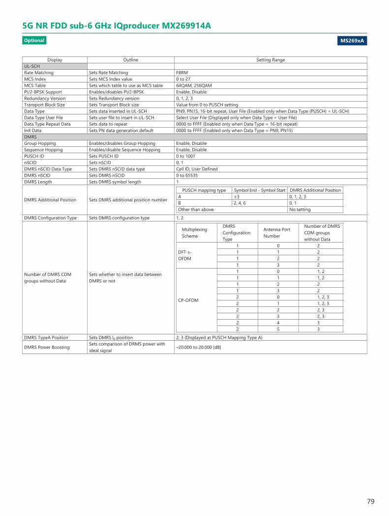
MS269xA
5G NR FDD sub-6 GHz IQproducer MX269914AOptional
Display Outline Setting RangeUL-SCHRate Matching Sets Rate Matching FBRMMCS Index Sets MCS Index value 0 to 27MCS Table Sets which table to use as MCS table 64QAM, 256QAMPI/2-BPSK Support Enables/disables PI/2-BPSK Enable, DisableRedundancy Version Sets Redundancy version 0, 1, 2, 3Transport Block Size Sets Transport Block size Value from 0 to PUSCH settingData Type Sets data inserted in UL-SCH PN9, PN15, 16-bit repeat, User File (Enabled only when Data Type (PUSCH) = UL-SCH) Data Type User File Sets user file to insert in UL-SCH Select User File (Displayed only when Data Type = User File) Data Type Repeat Data Sets data to repeat 0000 to FFFF (Enabled only when Data Type = 16-bit repeat) Init Data Sets PN data generation default 0000 to FFFF (Enabled only when Data Type = PN9, PN15) DMRSGroup Hopping Enables/disables Group Hopping Enable, DisableSequence Hopping Enables/disable Sequence Hopping Enable, DisablePUSCH ID Sets PUSCH ID 0 to 1007nSCID Sets nSCID 0, 1DMRS nSCID Data Type Sets DMRS nSCID data type Cell ID, User DefinedDMRS nSCID Sets DMRS nSCID 0 to 65535DMRS Length Sets DMRS symbol length 1
DMRS Additional Position Sets DMRS additional position number
PUSCH mapping type Symbol End – Symbol Start DMRS Additional PositionA ≥3 0, 1, 2, 3B 2, 4, 6 0, 1Other than above No setting
DMRS Configuration Type Sets DMRS configuration type 1, 2
Number of DMRS CDM groups without Data
Sets whether to insert data between DMRS or not
Multiplexing Scheme
DMRS Configuration Type
Antenna Port Number
Number of DMRS CDM groups without Data
DFT-s-OFDM
1 0 21 1 21 2 21 3 2
CP-OFDM
1 0 1, 21 1 1, 21 2 21 3 22 0 1, 2, 32 1 1, 2, 32 2 2, 32 3 2, 32 4 32 5 3
DMRS TypeA Position Sets DMRS l0 position 2, 3 (Displayed at PUSCH Mapping Type A)
DMRS Power BoostingSets comparison of DRMS power with ideal signal
–20.000 to 20.000 [dB]
79

Please specify the model/order number, name and quantity when ordering.The names listed in the chart below are Order Names. The actual name of the item may differ from the Order Name.
Model/Order No. Name
MS2690AMS2691AMS2692A
Main frameSignal Analyzer (50 Hz to 6.0 GHz)Signal Analyzer (50 Hz to 13.5 GHz)Signal Analyzer (50 Hz to 26.5 GHz)
MS2840A-040MS2840A-041
3.6 GHz Signal Analyzer (9 kHz to 3.6 GHz)6 GHz Signal Analyzer (9 kHz to 6.0 GHz)
MS2830A-040MS2830A-041MS2830A-043
3.6 GHz Signal Analyzer (9 kHz to 3.6 GHz)6 GHz Signal Analyzer (9 kHz to 6.0 GHz)13.5 GHz Signal Analyzer (9 kHz to 13.5 GHz)
MS2690A-020MS2691A-020MS2692A-020
Vector Signal Generator optionVector Signal Generator (125 MHz to 6 GHz)Vector Signal Generator (125 MHz to 6 GHz)Vector Signal Generator (125 MHz to 6 GHz)
MS2840A-020MS2840A-021MS2840A-022MS2840A-027MS2840A-028
3.6 GHz Vector Signal Generator (250 kHz to 3 GHz)6 GHz Vector Signal Generator (250 kHz to 6 GHz)Low Power Extension for Vector Signal GeneratorARB Memory Upgrade 256 MSa for Vector Signal GeneratorAWGN
MS2830A-020MS2830A-021MS2830A-022MS2830A-027MS2830A-028
3.6 GHz Vector Signal Generator (250 kHz to 3 GHz)6 GHz Vector Signal Generator (250 kHz to 6 GHz)Low Power Extension for Vector Signal GeneratorARB Memory Upgrade 256 MSa for Vector Signal GeneratorAWGN
Model/Order No. Name
MX269901AMX269902AMX269904AMX269908AMX269908A-001MX269910AMX269910A-001MX269911AMX269911A-001MX269912AMX269913AMX269914A
Software optionsCD-ROM with license and operation manualsHSDPA/HSUPA IQproducerTDMA IQproducerMulti-Carrier IQproducerLTE IQproducerLTE-Advanced FDD Option (Requires MX269908A)LTE TDD IQproducerLTE-Advanced TDD Option (Requires MX269910A)WLAN IQproducer802.11ac (80 MHz) Option (Requires MX269911A)TD-SCDMA IQproducer5G NR TDD sub-6 GHz IQproducer5G NR FDD sub-6 GHz IQproducer
W2915AEW2916AEW2917AEW3023AEW3221AEW3488AEW3582AEW3984AEW4033AE
Application partsFollowing operation manuals provided as hard copyMX269901A Operation ManualMX269902A Operation ManualMX269904A Operation ManualMX269908A Operation ManualMX269910A Operation ManualMX269911A Operation ManualMX269912A Operation ManualMX269913A Operation ManualMX269914A Operation Manual
Ordering Information
Anritsu Americas Sales Company 450 Century Parkway, Suite 190, Allen,TX 75013 U.S.A.Phone: +1-800-Anritsu (1-800-267-4878)
• CanadaAnritsu Electronics Ltd.700 Silver Seven Road, Suite 120, Kanata, Ontario K2V 1C3, CanadaPhone: +1-613-591-2003 Fax: +1-613-591-1006
• Brazil Anritsu Eletronica Ltda.
Phone: +55-11-3283-2511Fax: +55-11-3288-6940
• MexicoAnritsu Company, S.A. de C.V.Blvd Miguel de Cervantes Saavedra #169 Piso 1, Col. GranadaMexico, Ciudad de Mexico, 11520, MEXICOPhone: +52-55-4169-7104
• United KingdomAnritsu EMEA Ltd.
200 Capability Green, Luton, Bedfordshire, LU1 3LU, U.K.Phone: +44-1582-433200 Fax: +44-1582-731303
• FranceAnritsu S.A. 12 avenue du Québec, Bâtiment Iris 1- Silic 612,91140 VILLEBON SUR YVETTE, FrancePhone: +33-1-60-92-15-50Fax: +33-1-64-46-10-65
• GermanyAnritsu GmbHNemetschek Haus, Konrad-Zuse-Platz 1 81829 München, Germany Phone: +49-89-442308-0Fax: +49-89-442308-55
• ItalyAnritsu S.r.l.Via Elio Vittorini 129, 00144 Roma, ItalyPhone: +39-6-509-9711 Fax: +39-6-502-2425
• SwedenAnritsu ABIsafjordsgatan 32C, 164 40 KISTA, SwedenPhone: +46-8-534-707-00
• FinlandAnritsu ABTeknobulevardi 3-5, FI-01530 VANTAA, FinlandPhone: +358-20-741-8100Fax: +358-20-741-8111
• DenmarkAnritsu A/Sc/o Regus Fairway, Arne Jacobsens Allé 7, 5th floor, 2300 Copenhagen S, DenmarkPhone: +45-7211-2200
• RussiaAnritsu EMEA Ltd. Representation Office in RussiaTverskaya str. 16/2, bld. 1, 7th floor.Moscow, 125009, RussiaPhone: +7-495-363-1694Fax: +7-495-935-8962
• SpainAnritsu EMEA Ltd.Representation Office in SpainPaseo de la Castellana, 141. Planta 5, Edificio Cuzco IV28046, Madrid, SpainPhone: +34-91-572-6761
• United Arab EmiratesAnritsu EMEA Ltd.
Dubai Liaison Office
• P.R. China (Shanghai)Anritsu (China) Co., Ltd.Room 2701-2705, Tower A, New Caohejing International Business CenterNo. 391 Gui Ping Road Shanghai, 200233, P.R. ChinaPhone: +86-21-6237-0898Fax: +86-21-6237-0899
• P.R. China (Hong Kong)Anritsu Company Ltd.Unit 1006-7, 10/F., Greenfield Tower, Concordia Plaza,No. 1 Science Museum Road, Tsim Sha Tsui East, Kowloon, Hong Kong, P.R. ChinaPhone: +852-2301-4980Fax: +852-2301-3545
• JapanAnritsu Corporation
Phone: +81-46-296-6509Fax: +81-46-225-8352
8-5, Tamura-cho, Atsugi-shi, Kanagawa, 243-0016 Japan
• KoreaAnritsu Corporation, Ltd.5FL, 235 Pangyoyeok-ro, Bundang-gu, Seongnam-si, Gyeonggi-do, 13494 KoreaPhone: +82-31-696-7750Fax: +82-31-696-7751
• AustraliaAnritsu Pty. Ltd.
Phone: +61-3-9558-8177Fax: +61-3-9558-8255
• TaiwanAnritsu Company Inc.7F, No. 316, Sec. 1, NeiHu Rd., Taipei 114, TaiwanPhone: +886-2-8751-1816Fax: +886-2-8751-1817
1911
• SingaporeAnritsu Pte. Ltd.11 Chang Charn Road, #04-01, Shriro HouseSingapore 159640Phone: +65-6282-2400Fax: +65-6282-2533
• IndiaAnritsu India Private Limited6th Floor, Indiqube ETA, No.38/4, Adjacent to EMC2,Doddanekundi, Outer Ring Road, Bengaluru – 560048, IndiaPhone: +91-80-6728-1300Fax: +91-80-6728-1301
Specifications are subject to change without notice.
• United States
Unit 20, 21-35 Ricketts Road, Mount Waverley, Victoria 3149, Australia
902, Aurora Tower,P O Box: 500311- Dubai Internet CityDubai, United Arab EmiratesPhone: +971-4-3758479Fax: +971-4-4249036
Praça Amadeu Amaral, 27 - 1 Andar01327-010 - Bela Vista - Sao Paulo - SP, Brazil
Printed in Japan 11/MAR/2020 ddcm/CDT Catalog No. MX269xxxA-E-A-1-(24.00)