Embed Size (px)
Citation preview

Mitsubishi single-chip microcomputers
M16C/80 Series
Software Manual
Mitsubishi Electric Corporation, Kitaitami Works
Mitsubishi Electric Semiconductor Systems Corporation
REV. D

A table of symbols, a glossary, and an index are appended at the end of this manual.
Using This Manual
This manual is written for the M16C/80 series software. This manual can be used for all
types of microcomputers having the M16C/80 series CPU core.
The reader of this manual is expected to have the basic knowledge of electric and logic
circuits and microcomputers.
This manual consists of five chapters. The following lists the chapters and sections to be
referred to when you want to know details on some specific subject.
• To understand the outline of the M16C/80 series and its features Chapter 1, “Overview”
• To understand the operation of each addressing mode ..................Chapter 2, “Addressing Modes”
• To understand instruction functions
(Syntax, operation, function, selectable src/dest (label), flag changes, description example,
related instructions).............................................................................. Chapter 3, “Functions”
• To understand instruction code and cycles ......... Chapter 4, “Instruction Code/Number of Cycles”
This manual also contains quick references immediately after the Table of Contents. These
quick references will help you quickly find the pages for the functions or instruction code/
number of cycles you want to know.
• To find pages from mnemonic .................................. Quick Reference in Alphabetic Order
• To find pages from function and mnemonic ......................... Quick Reference by Function
• To find pages from mnemonic and addressing ................Quick Reference by Addressing

M16C Family-related document list
Usages
(Microcomputer development flow)
Outline designof system
Selection ofmicrocomputer
Detail designof system
Hard-waredevel-opment
Systemevaluation
Soft-waredevel-opment
Contents
Hardware specifications (pin assignment,memory map, specifications of peripheral func-tions, electrical characteristics, timing charts)
Detailed description about hardware specifica-tions, operation, and application examples(connection with peripherals, relationship withsoftware)
Method for creating programs using assemblyand C languages
Detailed description about operation of eachinstruction (assembly language)
Har
dwar
e
Type of document
Data sheet anddata book
User’s manualS
oftw
are
M16C Family M16C/80 Series M16C/80 Group
M16C/60 Series M16C/60 Group
M16C/61 Group
M16C/62 Group
M16C/20 Series M16C/20 Group
M16C/21 Group
M16C Family Line-up
Programmingmanual
Software manual

Table of Contents
Chapter 1 Overview ___________________________________________________
1.1 Features of M16C/80 series ...................................................................................................2
1.2 Address Space .......................................................................................................................3
1.3 Register Configuration ............................................................................................................4
1.4 Flag Register(FLG) .................................................................................................................7
1.5 Register Bank .........................................................................................................................9
1.6 Internal State after Reset is Cleared .....................................................................................10
1.7 Data Types ...........................................................................................................................11
1.8 Data Arrangement ................................................................................................................16
1.9 Instruction Format .................................................................................................................18
1.10 Vector Table .........................................................................................................................19
Chapter 2 Addressing Modes ___________________________________________
2.1 Addressing Modes ................................................................................................................22
2.2 Guide to This Chapter ...........................................................................................................23
2.3 General Instruction Addressing ............................................................................................24
2.4 Specific Instruction Addressing .............................................................................................27
2.5 Bit Instruction Addressing .....................................................................................................30
2.6 Bit Instruction Addressing .....................................................................................................32
2.7 Read and write operations with 24-bit registers ...................................................................35
Chapter 3 Functions___________________________________________________
3.1 Guide to This Chapter ..........................................................................................................38
3.2 Functions ..............................................................................................................................43
3.3 Index Instruction .................................................................................................................158
Chapter 4 Instruction Code/Number of Cycles ______________________________
4.1 Guide to This Chapter .........................................................................................................172
4.2 Instruction Code/Number of Cycles ....................................................................................174
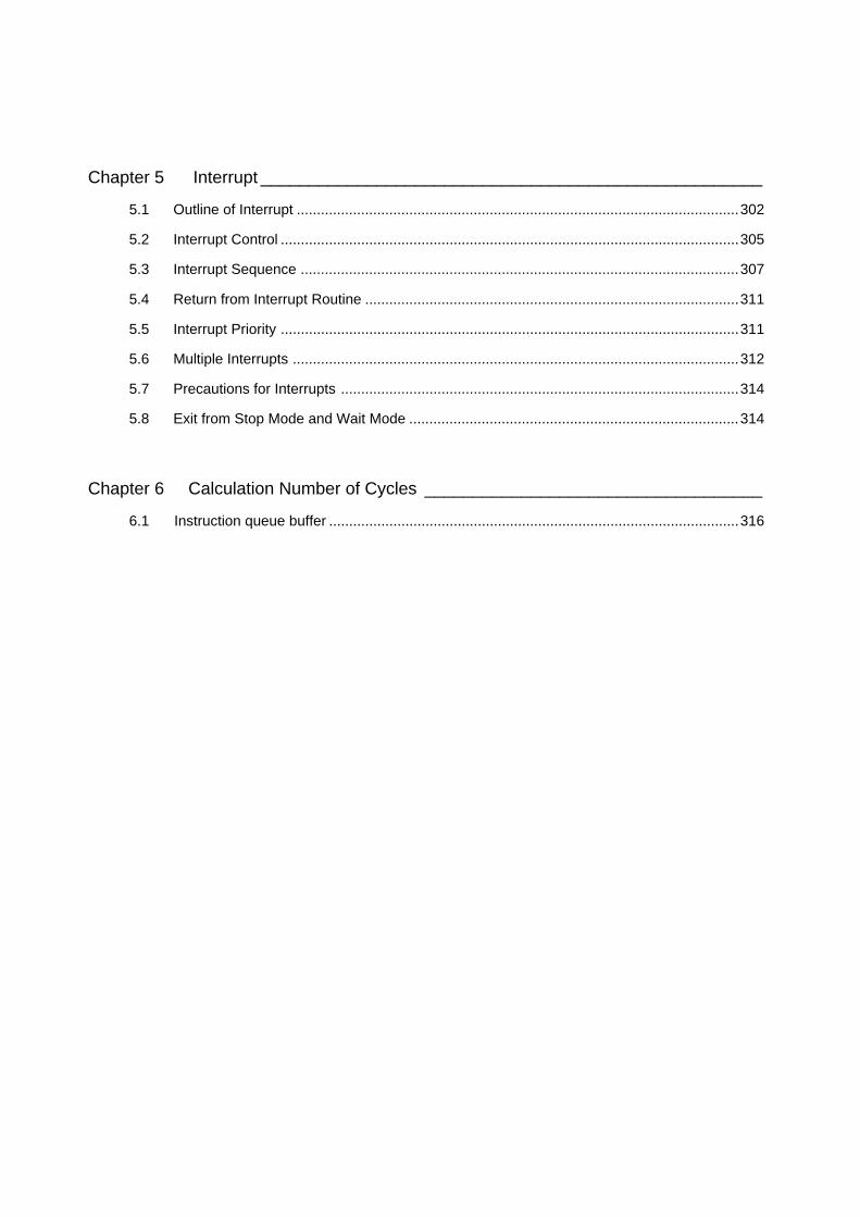
Chapter 5 Interrupt ____________________________________________________
5.1 Outline of Interrupt ..............................................................................................................302
5.2 Interrupt Control ..................................................................................................................305
5.3 Interrupt Sequence .............................................................................................................307
5.4 Return from Interrupt Routine .............................................................................................311
5.5 Interrupt Priority ..................................................................................................................311
5.6 Multiple Interrupts ...............................................................................................................312
5.7 Precautions for Interrupts ...................................................................................................314
5.8 Exit from Stop Mode and Wait Mode ..................................................................................314
Chapter 6 Calculation Number of Cycles ___________________________________
6.1 Instruction queue buffer ......................................................................................................316
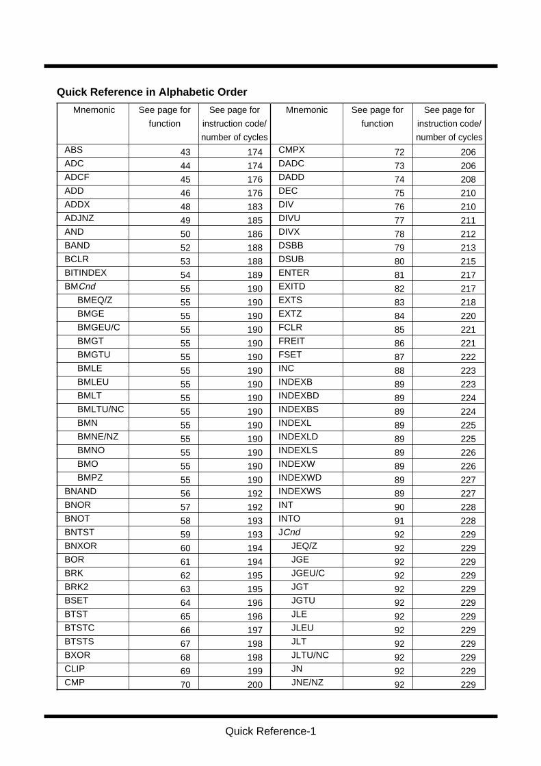
Quick Reference-1
CMPX
DADC
DADD
DEC
DIV
DIVU
DIVX
DSBB
DSUB
ENTER
EXITD
EXTS
EXTZ
FCLR
FREIT
FSET
INC
INDEXB
INDEXBD
INDEXBS
INDEXL
INDEXLD
INDEXLS
INDEXW
INDEXWD
INDEXWS
INT
INTO
JCnd
JEQ/Z
JGE
JGEU/C
JGT
JGTU
JLE
JLEU
JLT
JLTU/NC
JN
JNE/NZ
ABS
ADC
ADCF
ADD
ADDX
ADJNZ
AND
BAND
BCLR
BITINDEX
BMCnd
BMEQ/Z
BMGE
BMGEU/C
BMGT
BMGTU
BMLE
BMLEU
BMLT
BMLTU/NC
BMN
BMNE/NZ
BMNO
BMO
BMPZ
BNAND
BNOR
BNOT
BNTST
BNXOR
BOR
BRK
BRK2
BSET
BTST
BTSTC
BTSTS
BXOR
CLIP
CMP
See page for
function
Mnemonic See page for
instruction code/
number of cycles
See page for
function
MnemonicSee page for
instruction code/
number of cycles
43
44
45
46
48
49
50
52
53
54
55
55
55
55
55
55
55
55
55
55
55
55
55
55
55
56
57
58
59
60
61
62
63
64
65
66
67
68
69
70
174
174
176
176
183
185
186
188
188
189
190
190
190
190
190
190
190
190
190
190
190
190
190
190
190
192
192
193
193
194
194
195
195
196
196
197
198
198
199
200
Quick Reference in Alphabetic Order
206
206
208
210
210
211
212
213
215
217
217
218
220
221
221
222
223
223
224
224
225
225
226
226
227
227
228
228
229
229
229
229
229
229
229
229
229
229
229
229
72
73
74
75
76
77
78
79
80
81
82
83
84
85
86
87
88
89
89
89
89
89
89
89
89
89
90
91
92
92
92
92
92
92
92
92
92
92
92
92

Quick Reference-2
JNO
JPZ
JMP
JMPI
JMPS
JSR
JSRI
JSRS
LDC
LDCTX
LDIPL
MAX
MIN
MOV
MOVA
MOVDir
MOVHH
MOVHL
MOVLH
MOVLL
MOVX
MUL
MULEX
MULU
NEG
NOP
NOT
OR
POP
POPC
POPM
PUSH
PUSHA
PUSHC
PUSHM
REIT
RMPA
ROLC
RORC
ROT
RTS
SBB
SBJNZ
SCcnd
SCEQ/Z
SCGE
SCGEU/C
SCGT
SCGTU
SCLE
SCLEU
SCLT
SCLTU/NC
SCN
SCNE/NZ
SCNO
SCPZ
SCMPU
SHA
SHL
SIN
SMOVB
SMOVF
SMOVU
SOUT
SSTR
STC
STCTX
STNZ
STZ
STZX
SUB
SUBX
TST
UND
WAIT
XCHG
XOR
229
229
229
231
232
233
234
235
235
238
239
239
241
243
252
253
253
253
253
253
255
255
257
257
259
259
260
260
263
263
264
265
267
267
268
269
269
270
270
92
92
93
94
95
96
97
98
99
100
101
102
103
104
106
107
107
107
107
107
108
109
110
111
112
113
114
115
117
118
119
120
121
122
123
124
125
126
127
271
272
273
275
276
276
276
276
276
276
276
276
276
276
276
276
276
276
277
278
281
283
284
284
285
285
286
286
288
288
289
289
290
294
296
298
298
299
299
128
129
130
131
132
132
132
132
132
132
132
132
132
132
132
132
132
132
133
134
136
138
139
140
141
142
143
144
145
146
147
148
149
151
152
154
155
156
157
See page for
function
Mnemonic See page for
instruction code/
number of cycles
See page for
function
Mnemonic
Quick Reference in Alphabetic Order
See page for
instruction code/
number of cycles

Quick Reference-3
MOV Transfer
MOVA Transfer effective address
MOVDir Transfer 4-bit data
MOVX Transfer extend sign
POP Restore register/memory
POPM Restore multiple registers
PUSH Save register/memory/immediate data
PUSHA Save effective address
PUSHM Save multiple registers
STNZ Conditional transfer
STZ Conditional transfer
STZX Conditional transfer
XCHG Exchange
BAND Logically AND bits
BCLR Clear bit
BITINDEX Bit index
BMCnd Conditional bit transfer
BNAND Logically AND inverted bits
BNOR Logically OR inverted bits
BNOT Invert bit
BNTST Test inverted bit
BNXOR Exclusive OR inverted bits
BOR Logically OR bits
BSET Set bit
BTST Test bit
BTSTC Test bit & clear
BTSTS Test bit & set
BXOR Exclusive OR bits
ROLC Rotate left with carry
RORC Rotate right with carry
ROT Rotate
SHA Shift arithmetic
SHL Shift logical
ABS Absolute value
ADC Add with carry
ADCF Add carry flag
ADD Add without carry
ADDX Add extend sigh without carry
CLIP Clip
CMP Compare
104
106
107
108
117
119
120
121
123
146
147
148
156
52
53
54
55
56
57
58
59
60
61
64
65
66
67
68
126
127
128
134
136
43
44
45
46
48
69
70
Transfer
Bit
manupulation
Shift
Arithmetic
ContentFunction
243
252
253
255
263
264
265
267
268
288
289
289
299
188
188
189
190
192
192
193
193
194
194
196
196
197
198
198
270
270
271
278
281
174
174
176
176
183
199
200
Mnemonic See page for
instruction code/
number of cycles
See page for
function
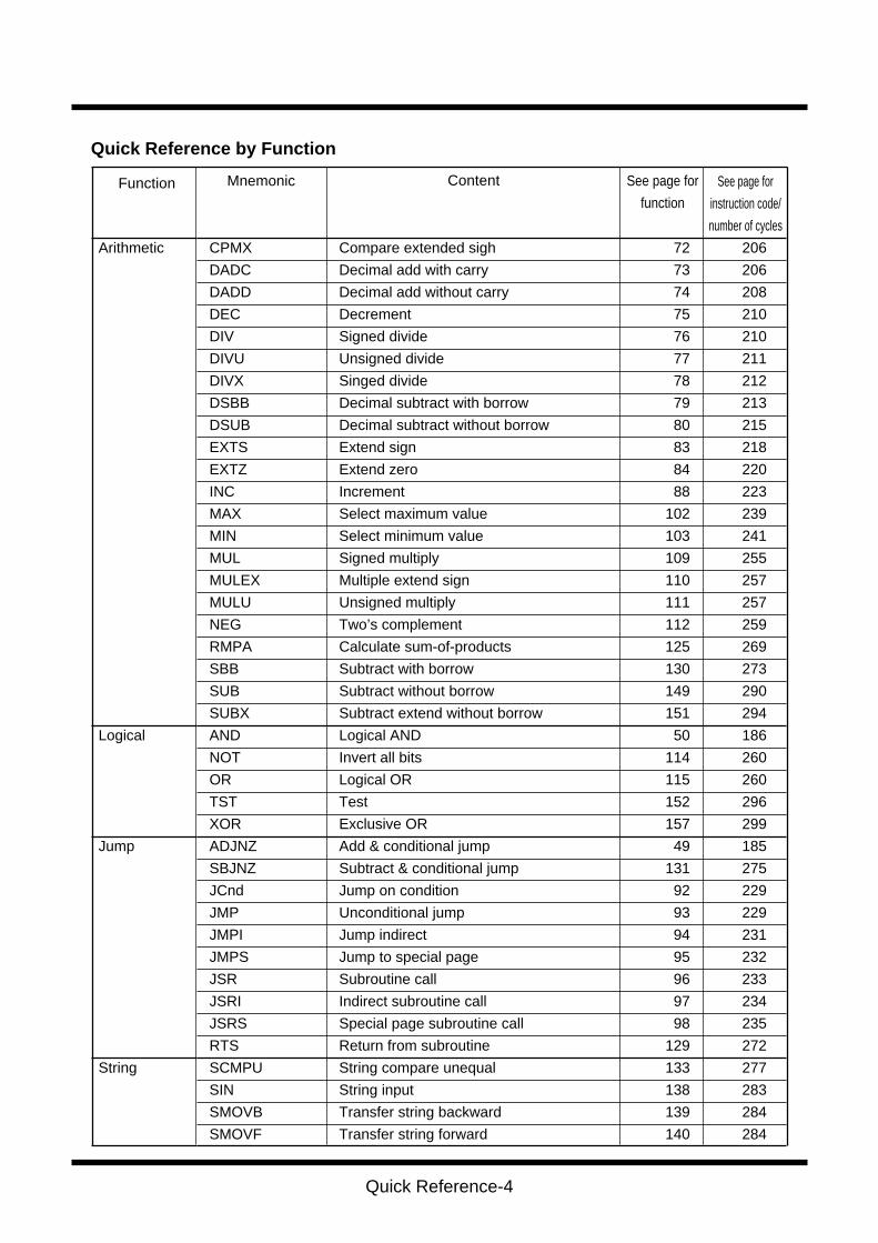
Quick Reference by Function
Quick Reference-4
CPMX Compare extended sigh
DADC Decimal add with carry
DADD Decimal add without carry
DEC Decrement
DIV Signed divide
DIVU Unsigned divide
DIVX Singed divide
DSBB Decimal subtract with borrow
DSUB Decimal subtract without borrow
EXTS Extend sign
EXTZ Extend zero
INC Increment
MAX Select maximum value
MIN Select minimum value
MUL Signed multiply
MULEX Multiple extend sign
MULU Unsigned multiply
NEG Two’s complement
RMPA Calculate sum-of-products
SBB Subtract with borrow
SUB Subtract without borrow
SUBX Subtract extend without borrow
AND Logical AND
NOT Invert all bits
OR Logical OR
TST Test
XOR Exclusive OR
ADJNZ Add & conditional jump
SBJNZ Subtract & conditional jump
JCnd Jump on condition
JMP Unconditional jump
JMPI Jump indirect
JMPS Jump to special page
JSR Subroutine call
JSRI Indirect subroutine call
JSRS Special page subroutine call
RTS Return from subroutine
SCMPU String compare unequal
SIN String input
SMOVB Transfer string backward
SMOVF Transfer string forward
Arithmetic
Logical
Jump
String
72
73
74
75
76
77
78
79
80
83
84
88
102
103
109
110
111
112
125
130
149
151
50
114
115
152
157
49
131
92
93
94
95
96
97
98
129
133
138
139
140
206
206
208
210
210
211
212
213
215
218
220
223
239
241
255
257
257
259
269
273
290
294
186
260
260
296
299
185
275
229
229
231
232
233
234
235
272
277
283
284
284
ContentFunction Mnemonic See page for
instruction code/
number of cycles
See page for
function
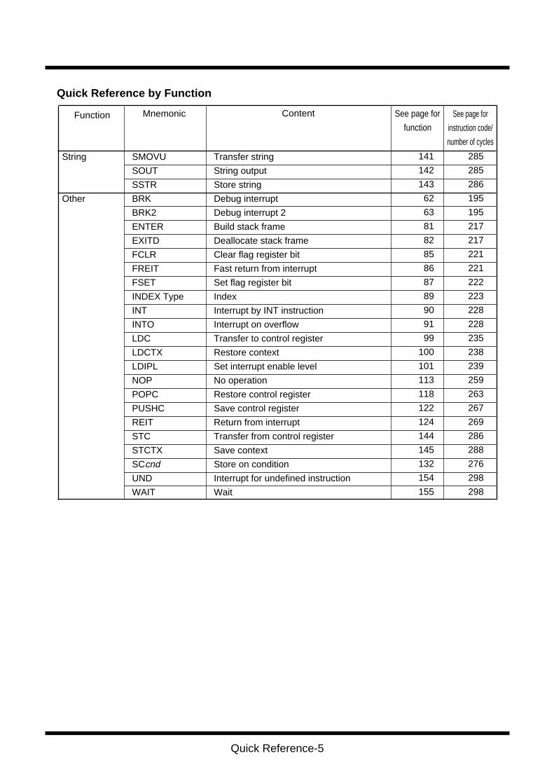
Quick Reference by Function
Quick Reference-5
SMOVU Transfer string
SOUT String output
SSTR Store string
BRK Debug interrupt
BRK2 Debug interrupt 2
ENTER Build stack frame
EXITD Deallocate stack frame
FCLR Clear flag register bit
FREIT Fast return from interrupt
FSET Set flag register bit
INDEX Type Index
INT Interrupt by INT instruction
INTO Interrupt on overflow
LDC Transfer to control register
LDCTX Restore context
LDIPL Set interrupt enable level
NOP No operation
POPC Restore control register
PUSHC Save control register
REIT Return from interrupt
STC Transfer from control register
STCTX Save context
SCcnd Store on condition
UND Interrupt for undefined instruction
WAIT Wait
String
Other
141
142
143
62
63
81
82
85
86
87
89
90
91
99
100
101
113
118
122
124
144
145
132
154
155
285
285
286
195
195
217
217
221
221
222
223
228
228
235
238
239
259
263
267
269
286
288
276
298
298
ContentFunction Mnemonic See page for
instruction code/
number of cycles
See page for
function
Quick Reference by Function
Quick reference-6
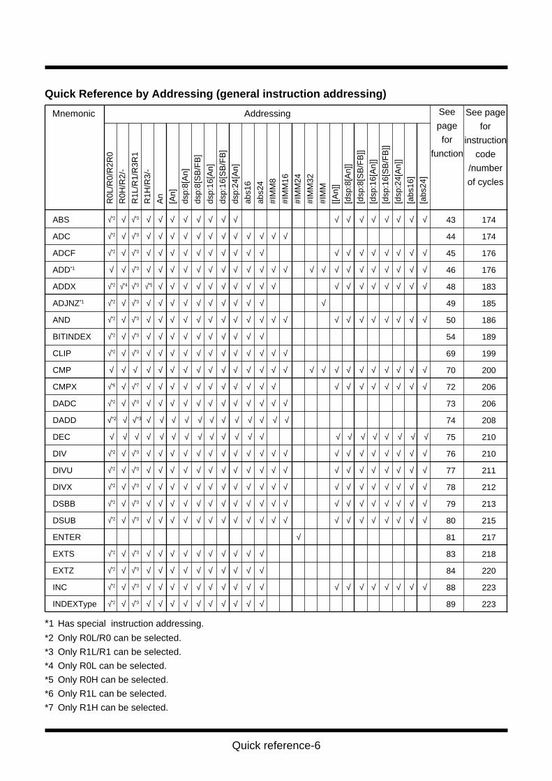
ABS √*2 √ √*3 √ √ √ √ √ √ √ √ √ √ √ √ √ √ √ √
ADC √*2 √ √*3 √ √ √ √ √ √ √ √ √ √ √ √
ADCF √*2 √ √*3 √ √ √ √ √ √ √ √ √ √ √ √ √ √ √ √ √ √
ADD*1 √ √ √*3 √ √ √ √ √ √ √ √ √ √ √ √ √ √ √ √ √ √ √ √ √ √
ADDX √*2 √*4 √*3 √*5 √ √ √ √ √ √ √ √ √ √ √ √ √ √ √ √ √ √
ADJNZ*1 √*2 √ √*3 √ √ √ √ √ √ √ √ √ √ √
AND √*2 √ √*3 √ √ √ √ √ √ √ √ √ √ √ √ √ √ √ √ √ √ √ √
BITINDEX √*2 √ √*3 √ √ √ √ √ √ √ √ √ √
CLIP √*2 √ √*3 √ √ √ √ √ √ √ √ √ √ √ √
CMP √ √ √ √ √ √ √ √ √ √ √ √ √ √ √ √ √ √ √ √ √ √ √ √ √
CMPX √*6 √ √*7 √ √ √ √ √ √ √ √ √ √ √ √ √ √ √ √ √ √ √
DADC √*2 √ √*3 √ √ √ √ √ √ √ √ √ √ √ √
DADD √*2 √ √*3 √ √ √ √ √ √ √ √ √ √ √ √
DEC √ √ √ √ √ √ √ √ √ √ √ √ √ √ √ √ √ √ √ √ √
DIV √*2 √ √*3 √ √ √ √ √ √ √ √ √ √ √ √ √ √ √ √ √ √ √ √
DIVU √*2 √ √*3 √ √ √ √ √ √ √ √ √ √ √ √ √ √ √ √ √ √ √ √
DIVX √*2 √ √*3 √ √ √ √ √ √ √ √ √ √ √ √ √ √ √ √ √ √ √ √
DSBB √*2 √ √*3 √ √ √ √ √ √ √ √ √ √ √ √ √ √ √ √ √ √ √ √
DSUB √*2 √ √*3 √ √ √ √ √ √ √ √ √ √ √ √ √ √ √ √ √ √ √ √
ENTER √
EXTS √*2 √ √*3 √ √ √ √ √ √ √ √ √ √
EXTZ √*2 √ √*3 √ √ √ √ √ √ √ √ √ √
INC √*2 √ √*3 √ √ √ √ √ √ √ √ √ √ √ √ √ √ √ √ √ √
INDEXType √*2 √ √*3 √ √ √ √ √ √ √ √ √ √
R0L
/R0/
R2R
0
R0H
/R2/
-
R1L
/R1/
R3R
1
R1H
/R3/
-
An
[An]
dsp:
8[A
n]
dsp:
8[S
B/F
B]
dsp:
16[A
n]
dsp:
16[S
B/F
B]
dsp:
24[A
n]
abs1
6
abs2
4
#IM
M8
#IM
M16
#IM
M24
#IM
M32
#IM
M
[[An]
]
[dsp
:8[A
n]]
[dsp
:8[S
B/F
B]]
[dsp
:16[
An]
]
[dsp
:16[
SB
/FB
]]
[dsp
:24[
An]
]
[abs
16]
[abs
24]
AddressingMnemonic
Quick Reference by Addressing (general instruction addressing)
*1 Has special instruction addressing.
*2 Only R0L/R0 can be selected.
*3 Only R1L/R1 can be selected.
*4 Only R0L can be selected.
*5 Only R0H can be selected.
*6 Only R1L can be selected.
*7 Only R1H can be selected.
43
44
45
46
48
49
50
54
69
70
72
73
74
75
76
77
78
79
80
81
83
84
88
89
174
174
176
176
183
185
186
189
199
200
206
206
208
210
210
211
212
213
215
217
218
220
223
223
See
page
for
function
See page
for
instruction
code
/number
of cycles
Quick reference-7
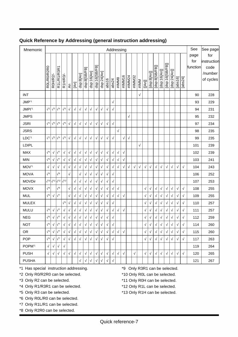
INT √
JMP*1 √
JMPI*1 √*2 √*3 √*4 √*5 √ √ √ √ √ √ √ √ √
JMPS √
JSRI √*2 √*3 √*4 √*5 √ √ √ √ √ √ √ √ √
JSRS √
LDC*1 √*2 √*3 √*4 √*5 √ √ √ √ √ √ √ √ √ √ √
LDIPL √
MAX √*6 √ √*7 √ √ √ √ √ √ √ √ √ √ √ √
MIN √*6 √ √*7 √ √ √ √ √ √ √ √ √ √ √ √
MOV*1 √ √ √ √ √ √ √ √ √ √ √ √ √ √ √ √ √ √ √ √ √ √ √ √ √ √
MOVA √*8 √*9 √ √ √ √ √ √ √ √
MOVDir √*10 √*11 √*12 √*13 √ √ √ √ √ √ √ √
MOVX √*8 √*9 √ √ √ √ √ √ √ √ √ √ √ √ √ √ √ √ √ √
MUL √*6 √ √*7 √ √ √ √ √ √ √ √ √ √ √ √ √ √ √ √ √ √ √
MULEX √*5 √ √ √ √ √ √ √ √ √ √ √ √ √ √ √ √ √
MULU √*6 √ √*7 √ √ √ √ √ √ √ √ √ √ √ √ √ √ √ √ √ √ √ √
NEG √*6 √ √*7 √ √ √ √ √ √ √ √ √ √ √ √ √ √ √ √ √ √
NOT √*6 √ √*7 √ √ √ √ √ √ √ √ √ √ √ √ √ √ √ √ √ √
OR √*6 √ √*7 √ √ √ √ √ √ √ √ √ √ √ √ √ √ √ √ √ √ √ √
POP √*6 √ √*7 √ √ √ √ √ √ √ √ √ √ √ √ √ √ √ √ √ √
POPM*1 √ √ √ √
PUSH √ √ √ √ √ √ √ √ √ √ √ √ √ √ √ √ √ √ √ √ √ √ √ √
PUSHA √ √ √ √ √ √ √
90
93
94
95
97
98
99
101
102
103
104
106
107
108
109
110
111
112
114
115
117
119
120
121
228
229
231
232
234
235
235
239
239
241
243
252
253
255
255
257
257
259
260
260
263
264
265
267
Quick Reference by Addressing (general instruction addressing)
*1 Has special instruction addressing.
*2 Only R0/R2R0 can be selected.
*3 Only R2 can be selected.
*4 Only R1/R3R1 can be selected.
*5 Only R3 can be selected.
*6 Only R0L/R0 can be selected.
*7 Only R1L/R1 can be selected.
*8 Only R2R0 can be selected.
R0L
/R0/
R2R
0
R0H
/R2/
-
R1L
/R1/
R3R
1
R1H
/R3/
-
An
[An]
dsp:
8[A
n]
dsp:
8[S
B/F
B]
dsp:
16[A
n]
dsp:
16[S
B/F
B]
dsp:
24[A
n]
abs1
6
abs2
4
#IM
M8
#IM
M16
#IM
M24
#IM
M32
#IM
M
[[An]
]
[dsp
:8[A
n]]
[dsp
:8[S
B/F
B]]
[dsp
:16[
An]
]
[dsp
:16[
SB
/FB
]]
[dsp
:24[
An]
]
[abs
16]
[abs
24]
*9 Only R3R1 can be selected.
*10 Only R0L can be selected.
*11 Only R0H can be selected.
*12 Only R1L can be selected.
*13 Only R1H can be selected.
AddressingMnemonic See
page
for
function
See page
for
instruction
code
/number
of cycles

Quick reference-8
R0L
/R0/
R2R
0
R0H
/R2/
-
R1L
/R1/
R3R
1
R1H
/R3/
-
An
[An]
dsp:
8[A
n]
dsp:
8[S
B/F
B]
dsp:
16[A
n]
dsp:
16[S
B/F
B]
dsp:
24[A
n]
abs1
6
abs2
4
#IM
M8
#IM
M16
#IM
M24
#IM
M32
#IM
M
[[An]
]
[dsp
:8[A
n]]
[dsp
:8[S
B/F
B]]
[dsp
:16[
An]
]
[dsp
:16[
SB
/FB
]]
[dsp
:24[
An]
]
[abs
16]
[abs
24]
PUSHM*1 √ √ √ √
ROLC √*2 √ √ √*3 √ √ √ √ √ √ √ √ √ √ √ √ √ √ √ √ √
RORC √*2 √ √ √*3 √ √ √ √ √ √ √ √ √ √ √ √ √ √ √ √ √
ROT √*2 √ √ √*3 √ √ √ √ √ √ √ √ √ √ √ √ √ √ √ √ √ √
SBB √*2 √ √ √*3 √ √ √ √ √ √ √ √ √ √ √
SBJNZ*1 √*2 √ √ √*3 √ √ √ √ √ √ √ √ √ √
SCCnd √*4 √*5 √*6 √*7 √ √ √ √ √ √ √ √ √ √ √ √ √ √ √ √ √
SHA √ √ √ √ √ √ √ √ √ √ √ √ √ √ √ √ √ √ √ √ √ √ √
SHL √ √ √ √ √ √ √ √ √ √ √ √ √ √ √ √ √ √ √ √ √ √
STC*1 √*4 √*5 √*6 √*7 √ √ √ √ √ √ √ √ √
STCTX*1 √ √ √ √
STNZ √*2 √ √ √*3 √ √ √ √ √ √ √ √ √ √ √ √ √ √ √ √ √ √ √
STZ √*2 √ √ √*3 √ √ √ √ √ √ √ √ √ √ √ √ √ √ √ √ √ √ √
STZX √*2 √ √ √*3 √ √ √ √ √ √ √ √ √ √ √ √ √ √ √ √ √ √ √
SUB √ √ √ √ √ √ √ √ √ √ √ √ √ √ √ √ √ √ √ √ √ √ √ √
SUBX √*8 √*9 √*10 √*11 √ √ √ √ √ √ √ √ √ √ √ √ √ √ √ √ √ √
TST √*2 √ √ √*3 √ √ √ √ √ √ √ √ √ √ √
XCHG √*2 √ √ √*3 √ √ √ √ √ √ √ √ √ √ √ √ √ √ √ √ √
XOR √*2 √ √ √*3 √ √ √ √ √ √ √ √ √ √ √ √ √ √ √ √ √ √ √
123
126
127
128
130
131
132
134
136
144
145
146
147
148
149
151
152
156
157
268
270
270
271
273
275
276
278
281
286
288
288
289
289
290
294
296
299
299
AddressingMnemonic
Quick Reference by Addressing (general instruction addressing)
See
page
for
function
See page
for
instruction
code
/number
of cycles
*1 Has special instruction addressing.
*2 Only R0L/R0 can be selected.
*3 Only R1L/R1 can be selected.
*4 Only R0 can be selected.
*5 Only R2 can be selected.
*6 Only R1 can be selected.
*7 Only R3 can be selected.
*8 Only R0L/R2R0 can be selected.
*9 Only R0H can be selected.
*10 Only R1L/R3R1 can be selected.
*11 Only R1H can be selected.
Quick reference-9
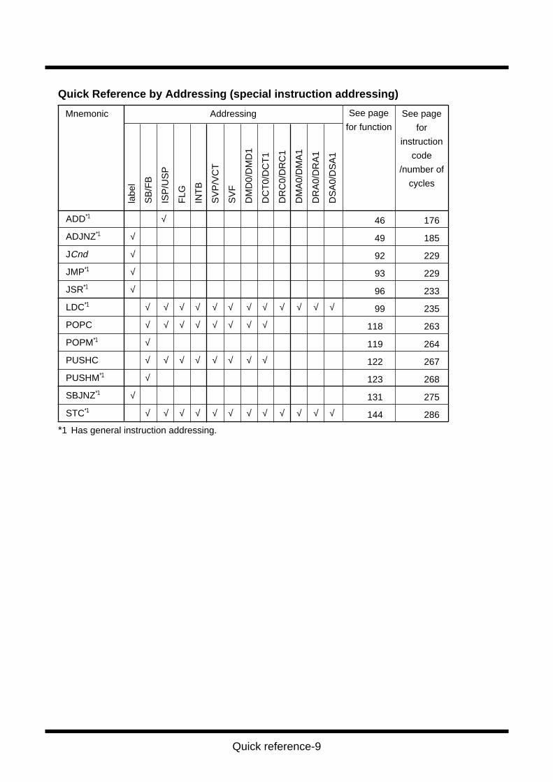
*1 Has general instruction addressing.
labe
l
SB
/FB
ISP
/US
P
FLG
INT
B
SV
P/V
CT
SV
F
DM
D0/
DM
D1
DC
T0/
DC
T1
DR
C0/
DR
C1
DM
A0/
DM
A1
DR
A0/
DR
A1
DS
A0/
DS
A1
ADD*1 √
ADJNZ*1 √
JCnd √
JMP*1 √
JSR*1 √
LDC*1 √ √ √ √ √ √ √ √ √ √ √ √
POPC √ √ √ √ √ √ √ √
POPM*1 √
PUSHC √ √ √ √ √ √ √ √
PUSHM*1 √
SBJNZ*1 √
STC*1 √ √ √ √ √ √ √ √ √ √ √ √
AddressingMnemonic
Quick Reference by Addressing (special instruction addressing)
46
49
92
93
96
99
118
119
122
123
131
144
176
185
229
229
233
235
263
264
267
268
275
286
See page
for functionSee page
for
instruction
code
/number of
cycles
Quick reference-10
bit,R
0L/R
0H
bit,R
1L/R
1H
bit,A
n
bit,[
An]
bit,b
ase:
11[A
n]
bit,b
ase:
11[S
B/F
B]
bit,b
ase:
19[A
n]
bit,b
ase:
19[S
B/F
B]
bit,b
ase:
27[A
n]
bit,b
ase:
27
bit,b
ase:
19
U/I/
O/B
/S/Z
/D/C
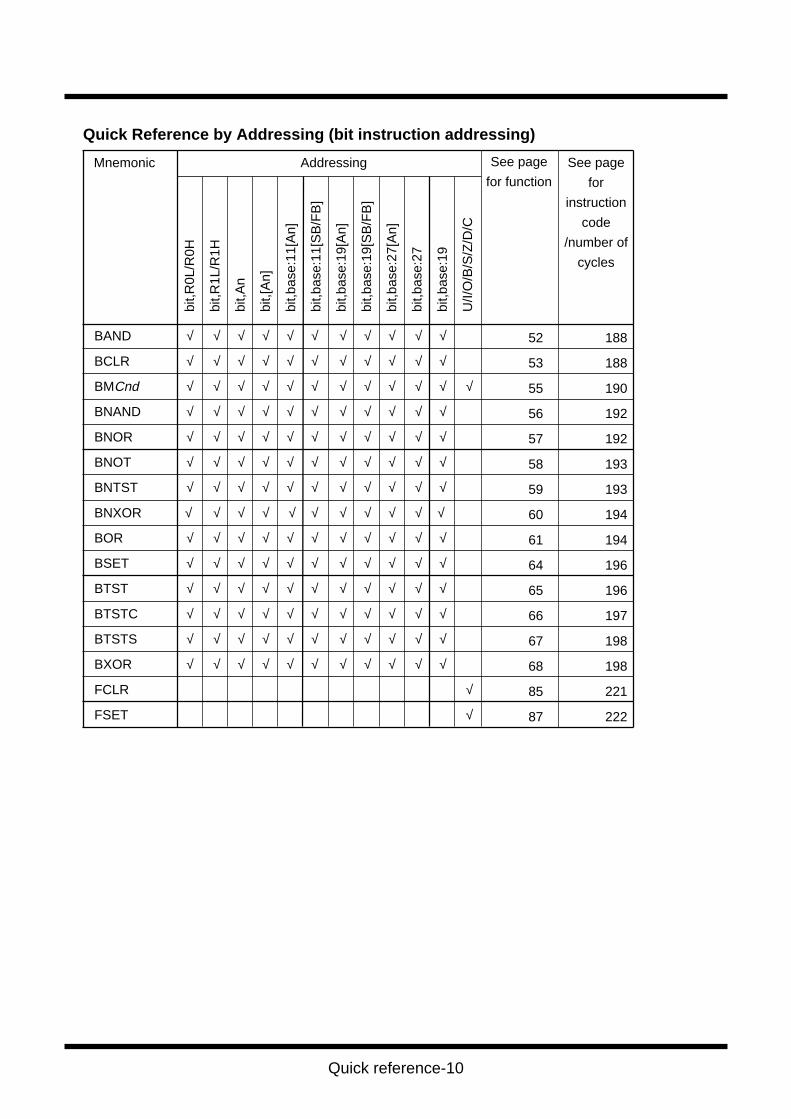
BAND √ √ √ √ √ √ √ √ √ √ √
BCLR √ √ √ √ √ √ √ √ √ √ √
BMCnd √ √ √ √ √ √ √ √ √ √ √ √
BNAND √ √ √ √ √ √ √ √ √ √ √
BNOR √ √ √ √ √ √ √ √ √ √ √
BNOT √ √ √ √ √ √ √ √ √ √ √
BNTST √ √ √ √ √ √ √ √ √ √ √
BNXOR √ √ √ √ √ √ √ √ √ √ √
BOR √ √ √ √ √ √ √ √ √ √ √
BSET √ √ √ √ √ √ √ √ √ √ √
BTST √ √ √ √ √ √ √ √ √ √ √
BTSTC √ √ √ √ √ √ √ √ √ √ √
BTSTS √ √ √ √ √ √ √ √ √ √ √
BXOR √ √ √ √ √ √ √ √ √ √ √
FCLR √
FSET √
52
53
55
56
57
58
59
60
61
64
65
66
67
68
85
87
188
188
190
192
192
193
193
194
194
196
196
197
198
198
221
222
AddressingMnemonic
Quick Reference by Addressing (bit instruction addressing)
See page
for functionSee page
for
instruction
code
/number of
cycles

Quick reference-11
Chapter 1
Overview
1.1 Features of M16C/80 series
1.2 Address Space
1.3 Register Configuration
1.4 Flag Register (FLG)
1.5 Register Bank
1.6 Internal State after Reset is Cleared
1.7 Data Types
1.8 Data Arrangement
1.9 Instruction Format
1.10 Vector Table
2
Chapter 1 Overview1.1 Features of M16C/80 series
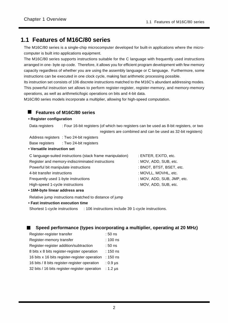
1.1 Features of M16C/80 seriesThe M16C/80 series is a single-chip microcomputer developed for built-in applications where the micro-
computer is built into applications equipment.
The M16C/80 series supports instructions suitable for the C language with frequently used instructions
arranged in one- byte op-code. Therefore, it allows you for efficient program development with few memory
capacity regardless of whether you are using the assembly language or C language. Furthermore, some
instructions can be executed in one clock cycle, making fast arithmetic processing possible.
Its instruction set consists of 106 discrete instructions matched to the M16C's abundant addressing modes.
This powerful instruction set allows to perform register-register, register-memory, and memory-memory
operations, as well as arithmetic/logic operations on bits and 4-bit data.
M16C/80 series models incorporate a multiplier, allowing for high-speed computation.
Features of M16C/80 series• Register configuration
Data registers : Four 16-bit registers (of which two registers can be used as 8-bit registers, or two
registers are combined and can be used as 32-bit registers)
Address registers : Two 24-bit registers
Base registers : Two 24-bit registers
• Versatile instruction set
C language-suited instructions (stack frame manipulation) : ENTER, EXITD, etc.
Register and memory-indiscriminated instructions : MOV, ADD, SUB, etc.
Powerful bit manipulate instructions : BNOT, BTST, BSET, etc.
4-bit transfer instructions : MOVLL, MOVHL, etc.
Frequently used 1-byte instructions : MOV, ADD, SUB, JMP, etc.
High-speed 1-cycle instructions : MOV, ADD, SUB, etc.
• 16M-byte linear address area
Relative jump instructions matched to distance of jump
• Fast instruction execution time
Shortest 1-cycle instructions : 106 instructions include 39 1-cycle instructions.
Speed performance (types incorporating a multiplier, operating at 20 MHz)Register-register transfer : 50 ns
Register-memory transfer : 100 ns
Register-register addition/subtraction : 50 ns
8 bits x 8 bits register-register operation : 150 ns
16 bits x 16 bits register-register operation : 150 ns
16 bits / 8 bits register-register operation : 0.9 µs
32 bits / 16 bits register-register operation : 1.2 µs
3
Chapter 1 Overview
The SFR area in each
model extends toward
lower-address locations
as much as available.
The RAM area in each
model extends toward
higher-address loca-
tions as much as
available.
1.2 Address Space
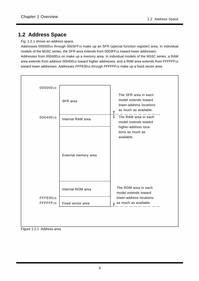
1.2 Address SpaceFig. 1.2.1 shows an address space.
Addresses 00000016 through 0003FF16 make up an SFR (special function register) area. In individual
models of the M16C series, the SFR area extends from 0003FF16 toward lower addresses.
Addresses from 00040016 on make up a memory area. In individual models of the M16C series, a RAM
area extends from address 00040016 toward higher addresses, and a R0M area extends from FFFFFF16
toward lower addresses. Addresses FFFE0016 through FFFFFF16 make up a fixed vector area.
Figure 1.2.1 Address area
00000016
00040016
FFFE0016
FFFFFF16
SFR area
Internal RAM area
External memory area
Internal ROM area
Fixed vector area
The ROM area in each
model extends toward
lower-address locations
as much as available.

4
Chapter 1 Overview1.3 Register Configuration
1.3 Register ConfigurationThe central processing unit (CPU) contains the 28 registers shown in Figure 1.3.1. Of these registers, R0,
R1, R2, R3, A0, A1, FB, and SB each consist of two sets of registers configuring two register banks.
Figure 1.3.1 CPU register configuration
b23
b7 b0
Flag register
Address register
Static base register
Frame base register
User stack pointer
Interrupt stack pointer
Interrupt table register
Save flag register
Save PC register
Vector register
DMA mode register
DMA transfer count register
DMA transfer count reload register
DMA memory address register
DMA SFR address register
DMA memory address reload register
b15 b0
b15 b0
b23
b15
b23
Data register
FLG
R0H
R1H
R2
R3
A0
A1
SB
FB
USP
ISP
INTB
PC
SVF
VCT
DMD0
DMD1
DCT0
DCT1
DRC0
DRC1
DMA0
DMA1
DSA0
DSA1
DRA0
DRA1
SVP
DMAC related register
Program counter
R2
R3
High-speed interrupt register
General register
b31
R0L
R1L
5
Chapter 1 Overview
(1) Data registers (R0, R0H, R0L, R1, R1H, R1L, R2, R3, R2R0, and R3R1)These registers consist of 16 bits, and are used primarily for transfers and arithmetic/logic operations.
Registers R0 and R1 can be halved into separate high-order (R0H, R1H) and low-order (R0L, R1L) parts
for use as 8-bit data registers. Moreover, you can combine R2 and R0 or R3 and R1 to configure a 32-
bit data register (R2R0 or R3R1).
(2) Address registers (A0 and A1)
These registers consist of 24 bits, and have the similar functions as the data registers. These registers
are used for address register-based indirect addressing and address register-based relative address-
ing.
(3) Static base register (SB)This register consists of 24 bits, and is used for SB-based relative addressing.
(4) Frame base register (FB)This register consists of 24 bits, and is used for FB-based relative addressing.
(5) Program counter (PC)This counter consists of 24 bits, indicating the address of an instruction to be executed next.
(6) Interrupt table register (INTB)This register consists of 24 bits, indicating the initial address of an interrupt vector table.
(7) User stack pointer (USP) and interrupt stack pointer (ISP)There are two types of stack pointers: user stack pointer (USP) and interrupt stack pointer (ISP), each
consisting of 24 bits.
The stack pointer (USP/ISP) you want can be switched by a stack pointer select flag (U flag).
The stack pointer select flag (U flag) is bit 7 of the flag register (FLG).
Set an even number to USP and ISP. When an even number is set, execution becomes efficient.
(8) Flag register (FLG)This register consists of 11 bits, and is used as a flag, one bit for one flag. For details about the function
of each flag, see Section 1.4, "Flag Register (FLG)."
(9) Save flag register (SVF)
This register consists of 16 bits and is used to save the flag register when a high-speed interrupt is
generated.
(10) Save PC register (SVP)
This register consists of 16 bits and is used to save the program counter when a high-speed interrupt is
generated.
1.3 Register Configuration

6
Chapter 1 Overview
(11) Vector register (VCT)This register consists of 24 bits and is used to indicate the jump address when a high-speed interrupt is
generated.
(12) DMA mode registers (DMD0/DMD1)
These registers consist of 8 bits and are used to set the transfer mode, etc. for DMA.
(13) DMA transfer count registers (DCT0/DCT1) These registers consist of 16 bits and are used to set the number of DMA transfers performed.
(14) DMA transfer count reload registers (DRC0/DRC1)These registers consist of 16 bits and are used to reload the DMA transfer count registers.
(15) DMA memory address registers (DMA0/DMA1)These registers consist of 24 bits and are used to set a memory address at the source or destination of
DMA transfer.
(16) DMA SFR address registers (DSA0/DSA1)
These registers consist of 24 bits and are used to set a fixed address at the source or destination of
DMA transfer.
(17) DMA memory address reload registers (DRA0/DRA1)
These registers consist of 24 bits and are used to reload the DMA memory address registers.
1.3 Register Configuration

7
Chapter 1 Overview1.4 Flag Register (FLG)
1.4 Flag Register (FLG)Figure 1.4.1 shows a configuration of the flag register (FLG). The function of each flag is detailed below.
(1) Bit 0: Carry flag (C flag)This flag holds a carry, borrow, or shifted-out bit that has occurred in the arithmetic/logic unit.
(2) Bit 1: Debug flag (D flag)This flag enables a single-step interrupt.
When this flag is set (= 1), a single-step interrupt is generated after an instruction is executed. When
an interrupt is acknowledged, this flag is cleared to 0.
(3) Bit 2: Zero flag (Z flag)This flag is set when an arithmetic operation resulted in 0; otherwise, this flag is 0.
(4) Bit 3: Sign flag (S flag)This flag is set when an arithmetic operation resulted in a negative value; otherwise, this flag is 0.
(5) Bit 4: Register bank select flag (B flag)This flag selects a register bank. If this flag is 0, register bank 0 is selected; when the flag is 1,
register bank 1 is selected.
(6) Bit 5: Overflow flag (O flag)This flag is set when an arithmetic operation resulted in overflow.
(7) Bit 6: Interrupt enable flag (I flag)This flag enables a maskable interrupt.
When this flag is 0, the interrupt is disabled; when the flag is 1, the interrupt is enabled. When the
interrupt is acknowledged, this flag is cleared to 0.
(8) Bit 7: Stack pointer select flag (U flag)When this flag is 0, the interrupt stack pointer (ISP) is selected; when the flag is 1, the user stack
pointer (USP) is selected.
This flag is cleared to 0 when a hardware interrupt is acknowledged or an INT instruction of software
interrupt numbers 0 to 31 is executed.
(9) Bits 8-11: Reserved area

8
Chapter 1 Overview1.4 Flag Register (FLG)
Figure 1.4.1 Configuration of flag register (FLG)
IPL U I O B S Z D C
b15 b0
Carry flag
Debug flag
Zero flag
Sign flag
Register bank select flag
Overflow flag
Interrupt enable flag
Stack pointer select flag
Reserved area
Processor interrupt priority level
Reserved area
Flag register (FLG)
(10) Bits 12-14: Processor interrupt priority level (IPL)The processor interrupt priority level (IPL) consists of three bits, allowing you to specify eight processor
interrupt priority levels from level 0 to level 7. If a requested interrupt's priority level is higher than the
processor interrupt priority level (IPL), this interrupt is enabled.
(11) Bit 15: Reserved area
9
Chapter 1 Overview1.5 Register Bank
Figure 1.5.1 Configuration of register banks
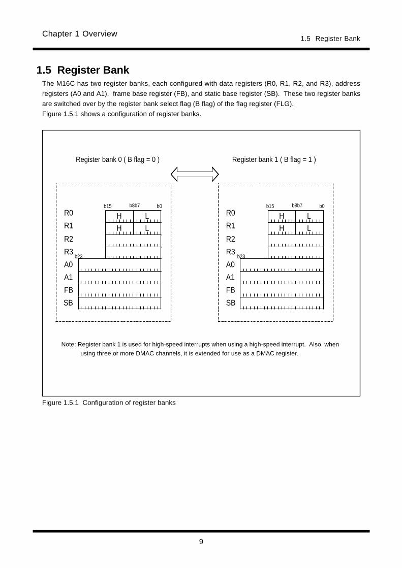
1.5 Register BankThe M16C has two register banks, each configured with data registers (R0, R1, R2, and R3), address
registers (A0 and A1), frame base register (FB), and static base register (SB). These two register banks
are switched over by the register bank select flag (B flag) of the flag register (FLG).
Figure 1.5.1 shows a configuration of register banks.
Note: Register bank 1 is used for high-speed interrupts when using a high-speed interrupt. Also, when
using three or more DMAC channels, it is extended for use as a DMAC register.
Register bank 1 ( B flag = 1 )Register bank 0 ( B flag = 0 )
b8b7 b0b15R0
R1
R2
R3
A0
A1
FB
SB
b23
LH
LH
b8b7 b0b15R0
R1
R2
R3
A0
A1
FB
SB
b23
LH
LH
10
Chapter 1 Overview1.6 Internal State after Reset is Cleared
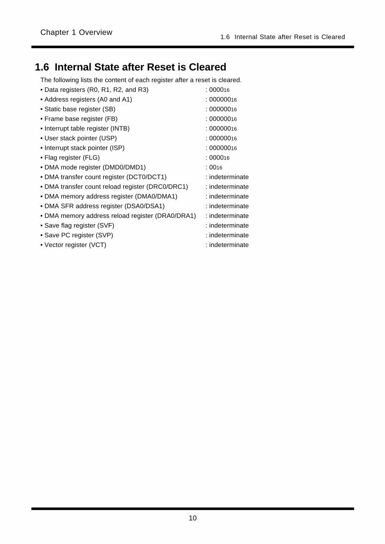
1.6 Internal State after Reset is ClearedThe following lists the content of each register after a reset is cleared.
• Data registers (R0, R1, R2, and R3) : 000016
• Address registers (A0 and A1) : 00000016
• Static base register (SB) : 00000016
• Frame base register (FB) : 00000016
• Interrupt table register (INTB) : 00000016
• User stack pointer (USP) : 00000016
• Interrupt stack pointer (ISP) : 00000016
• Flag register (FLG) : 000016
• DMA mode register (DMD0/DMD1) : 0016
• DMA transfer count register (DCT0/DCT1) : indeterminate
• DMA transfer count reload register (DRC0/DRC1) : indeterminate
• DMA memory address register (DMA0/DMA1) : indeterminate
• DMA SFR address register (DSA0/DSA1) : indeterminate
• DMA memory address reload register (DRA0/DRA1) : indeterminate
• Save flag register (SVF) : indeterminate
• Save PC register (SVP) : indeterminate
• Vector register (VCT) : indeterminate
11
Chapter 1 Overview1.7 Data Types
b7 b0
b7 b0
S
b15 b0
S
Signed byte (8 bit) integer
Unsigned byte (8 bit) integer
Signed word (16 bit) integer
Unsigned word (16 bit) integer
Signed long word (32 bit) integer
Unsigned long word (32 bit) integer
S: Sign bit
S
b31 b0
b31 b0
b15 b0
Figure 1.7.1 Integer data
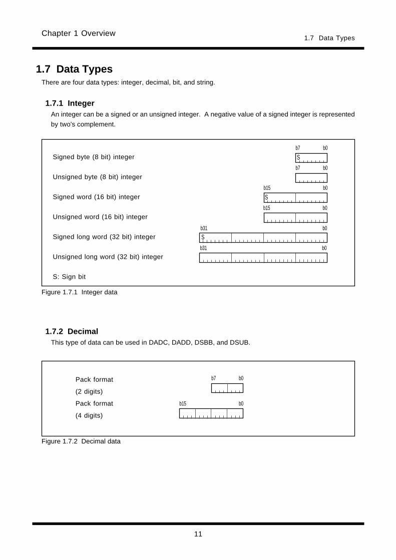
1.7 Data TypesThere are four data types: integer, decimal, bit, and string.
1.7.1 IntegerAn integer can be a signed or an unsigned integer. A negative value of a signed integer is represented
by two's complement.
1.7.2 DecimalThis type of data can be used in DADC, DADD, DSBB, and DSUB.
Pack format
(2 digits)
Pack format
(4 digits)
Figure 1.7.2 Decimal data
b15 b0
b7 b0

12
Chapter 1 Overview1.7 Data Types
1.7.3 Bits
(1) Register bitsFigure 1.7.3 shows register bit specification.
Register bits can be specified by register direct (bit,RnH/RnL or bit,An ). Use bit,RnH/RnL to specify
a bit in data register (RnH/RnL ); use bit,An to specify a bit in address register (An ).
For bit in bit,RnH/RnL and bit,An , you can specify a bit number in the range of 0 to 7.
Figure 1.7.3 Register bit specification
(2) Memory bitsFigure 1.7.4 shows addressing modes used for memory bit specification. Table 1.7.1 lists the address
range in which you can specify bits in each addressing mode. Be sure to observe the address range in
Table 1.7.1 when specifying memory bits.
Figure 1.7.4 Addressing modes used for memory bit specification
Addressing
Specification range The access range
Lower limit (address) Upper limit (address)
bit,base:19 00000016 00FFFF16
bit,base:27 00000016 FFFFFF16
bit,base:11[SB] [SB] [SB]+000FF16 00000016 to FFFFFF16.
bit,base:19[SB] [SB] [SB]+0FFFF16 00000016 to FFFFFF16.
bit,base:11[FB] [FB]-00008016 [FB]+00007F16 00000016 to FFFFFF16.
bit,base:19[FB] [FB]-00800016 [FB]+007FFF16 00000016 to FFFFFF16.
bit,[An] 00000016 FFFFFF16
bit,base:11[An] [An] [An]+0000FF16 00000016 to FFFFFF16.
bit,base:19[An] [An] [An]+00FFFF16 00000016 to FFFFFF16.
bit,base:27[An] [An] [An]+FFFFFF16 00000016 to FFFFFF16.
Table 1.7.1 Bit-Specifying Address Range
b7 b0bit,RnH/RnL
(bit:0 to 7, n:0,1)
RnH/RnLb7 b0
bit,An
(bit:0 to 7, n:0,1)
An
Absolute addressing bit,base:19
SB-based relative addressing bit,base:11[SB]bit,base:19[SB]
FB-based relative addressing bit,base:11[FB]
Address register-based indirect addressing
bit,[An]
Address register-based relative addressing
bit,base:11[An]bit,base:19[An]
Addressing modebit,base:27
bit,base:19[FB]
bit,base:27[An]

13
Chapter 1 Overview1.7 Data Types
Figure 1.7.6 Examples of how to specify bit 2 of address 0000A16
(1) Bit specification by bit, baseFigure 1.7.5 shows the relationship between memory map and bit map.
Memory bits can be handled as an array of consecutive bits. Bits can be specified by a given combina-
tion of bit and base . Using bit 0 of the address that is set to base as the reference (= 0), set the desired
bit position to bit . Figure 1.7.6 shows examples of how to specify bit 2 of address 0000A16.
Figure 1.7.5 Relationship between memory map and bit map
0
n-1
nn+1
n+1 n n-1 0b7 b0b7 b0b7 b0 b7 b0
b7 b0Address
Memory map Bit
BSET 2,AH ;
b7 b2 b0
Address 0000A16
b15 b10 b8b7 b0Address 0000916
b87 b82 b80b79 b72 b7 b0Address 0000016
b23 b18 b16b15 b8b7 b0Address 0000816
BSET 10,9H ;
BSET 18,8H ;
BSET 82,0H ;
These specificationexamples all specifybit 2 of address0000A16
14
Chapter 1 Overview1.7 Data Types
(2) SB/FB relative bit specificationFor SB/FB-based relative addressing, use bit 0 of the address that is the sum of the address set to
static base register (SB) or frame base register (FB) plus the address set to base as the reference (=
0), and set the desired bit position to bit .
(3) Address register indirect/relative bit specificationFor address register indirect addressing, use bit 0 of the address that is set to address register(An )
as the reference (= 0), and set the desired bit position to bit .
For address register indirect addressing, specified bit range is 0 to 7.
For address register relative addressing, use bit 0 of the address that is the sum of the address set to
address register (An ) plus the address set to base as the reference (= 0), and set the desired bit
position to bit .
15
Chapter 1 Overview1.7 Data Types
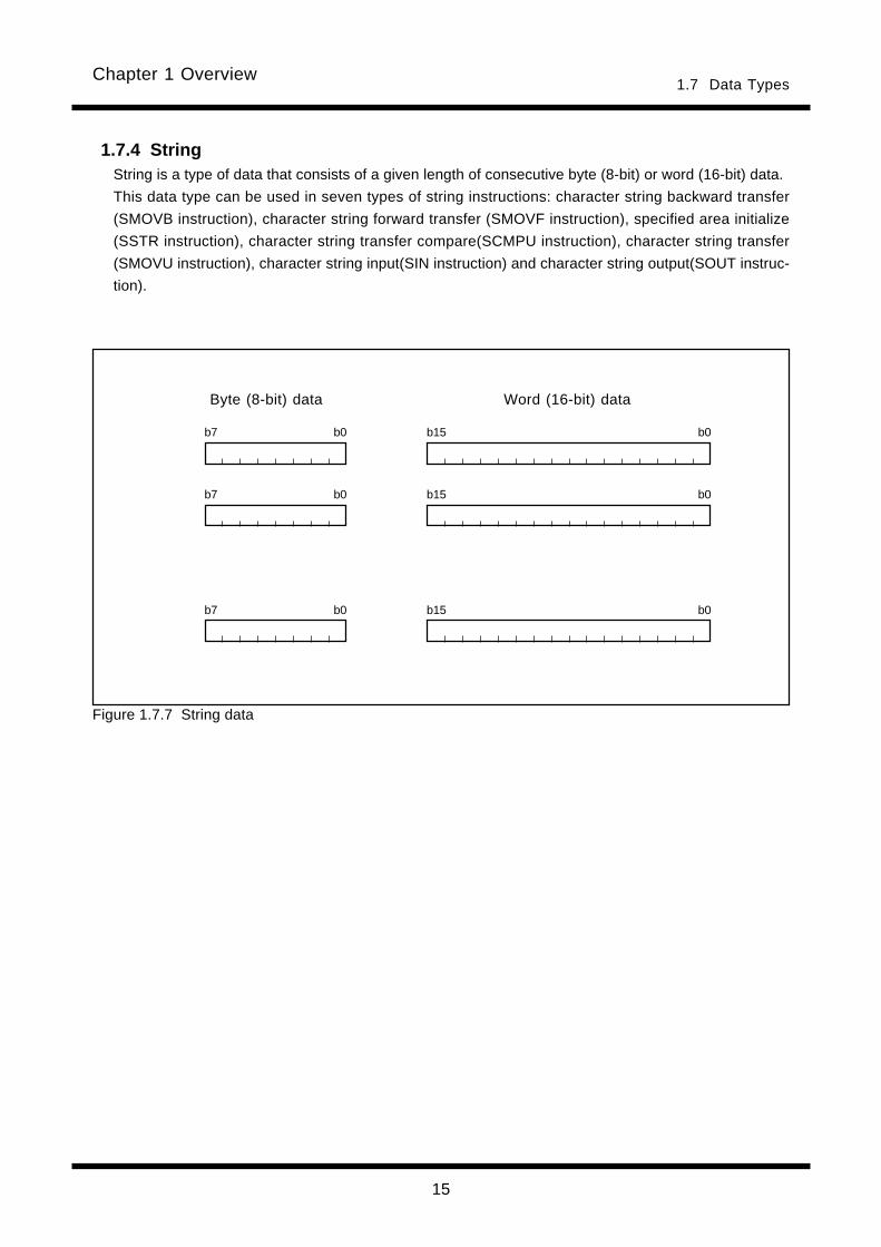
1.7.4 StringString is a type of data that consists of a given length of consecutive byte (8-bit) or word (16-bit) data.
This data type can be used in seven types of string instructions: character string backward transfer
(SMOVB instruction), character string forward transfer (SMOVF instruction), specified area initialize
(SSTR instruction), character string transfer compare(SCMPU instruction), character string transfer
(SMOVU instruction), character string input(SIN instruction) and character string output(SOUT instruc-
tion).
b15 b0
b7 b0
b7 b0
b7 b0
b15 b0
b15 b0
Figure 1.7.7 String data
Byte (8-bit) data Word (16-bit) data

16
Chapter 1 Overview1.8 Data Arrangement
1.8 Data Arrangement1.8.1 Data Arrangement in Register
Figure 1.8.1 shows the relationship between a register's data size and bit numbers.
b15 b0
b3 b0
b7 b0
MSB LSB
b31 b0
Nibble (4-bit) data
Byte (8-bit) data
Word (16-bit) data
Long word (32-bit) data
Figure 1.8.1 Data arrangement in register

17
Chapter 1 Overview
b7 b0
N DATA(L)
N+1 DATA(H)
N+2
N+3
b7 b0
N DATA
N+1
N+2
N+3
MOV.B N,R0H
MOV.W N,R0
R0H L
b15 b0
R0H L
b15 b0
DATA
DATA(H) DATA(L)
Word (16-bit) data
Byte (8-bit) data
1.8 Data Arrangement
Figure 1.8.2 Data arrangement in memory
Does not change.
1.8.2 Data Arrangement in MemoryFigure 1.8.2 shows data arrangement in memory. Figure 1.8.3 shows some examples of operation.
b7 b0
N DATA
N+1
N+2
N+3
b7 b0
N DATA(L)
N+1 DATA(H)
N+2
N+3
b7 b0
N DATA(L)
N+1 DATA(M)
N+2 DATA(H)
N+3
b7 b0
N DATA(LL)
N+1 DATA(LH)
N+2 DATA(HL)
N+3 DATA(HH)
Word (16-bit) dataByte (8-bit) data
Long Word (32-bit) data24-bit (Address) data
Figure 1.8.3 Examples of operation
18
Chapter 1 Overview1.9 Instruction Format
1.9 Instruction FormatThe instruction format can be classified into four types: generic, quick, short, and zero. The number of
instruction bytes that can be chosen by a given format is least for the zero format, and increases succes-
sively for the short, quick, and generic formats in that order.
The following describes the features of each format.
(1) Generic format (:G)Op-code in this format consists of 2 bytes. This op-code contains information on operation and src*1 and
dest*2 addressing modes.
Instruction code here is comprised of op-code (2-3 bytes), src code (0-4 bytes), and dest code (0-3
bytes).
(2) Quick format (:Q)Op-code in this format consists of two bytes. This op-code contains information on operation and imme-
diate data and dest addressing modes. Note however that the immediate data in this op-code is a
numeric value that can be expressed by -7 to +8 or -8 to +7 (varying with instruction).
Instruction code here is comprised of op-code (2 bytes) containing immediate data and dest code (0-3
bytes).
(3) Short format (:S)Op-code in this format consists of one byte. This op-code contains information on operation and src and
dest addressing modes.Note however that the usable addressing modes are limited.
Instruction code here is comprised of op-code (1 byte), src code (0-2 bytes), and dest code (0-2 bytes).
(4) Zero format (:Z)Op-code in this format consists of one byte. This op-code contains information on operation (plus
immediate data) and dest addressing modes. Note however that the immediate data is fixed to 0, and
that the usable addressing modes are limited.
Instruction code here is comprised of op-code (1 byte) and dest code (0-2 bytes).
*1 src is the abbreviation of "source."
*2 dest is the abbreviation of "destination."
19
Chapter 1 Overview
255
254
18
1.10 Vector Table
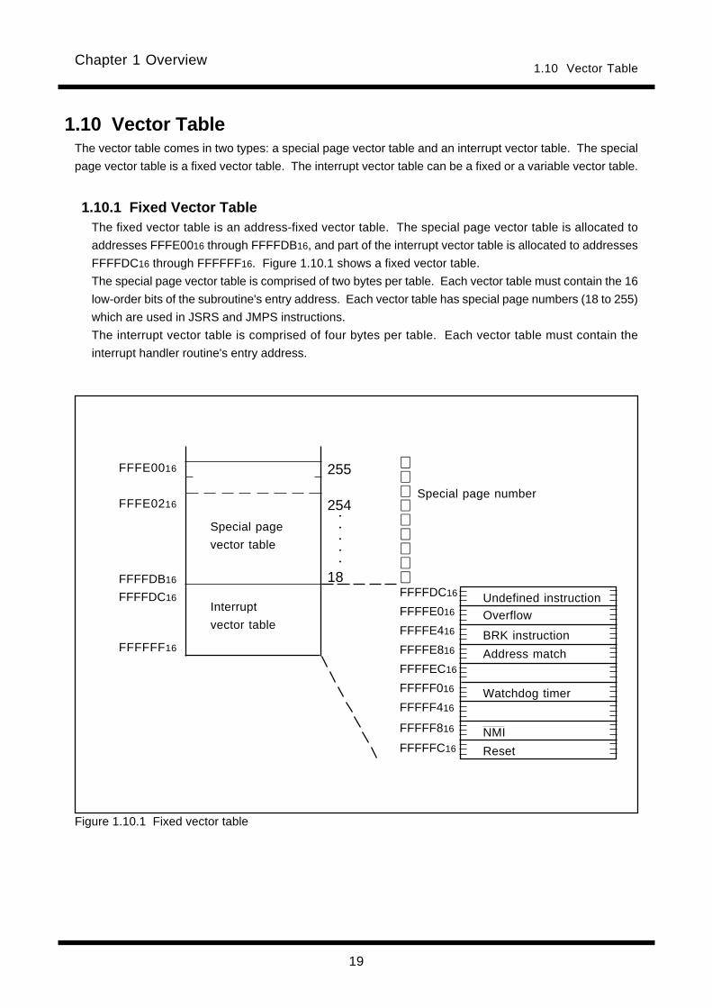
1.10 Vector TableThe vector table comes in two types: a special page vector table and an interrupt vector table. The special
page vector table is a fixed vector table. The interrupt vector table can be a fixed or a variable vector table.
1.10.1 Fixed Vector TableThe fixed vector table is an address-fixed vector table. The special page vector table is allocated to
addresses FFFE0016 through FFFFDB16, and part of the interrupt vector table is allocated to addresses
FFFFDC16 through FFFFFF16. Figure 1.10.1 shows a fixed vector table.
The special page vector table is comprised of two bytes per table. Each vector table must contain the 16
low-order bits of the subroutine's entry address. Each vector table has special page numbers (18 to 255)
which are used in JSRS and JMPS instructions.
The interrupt vector table is comprised of four bytes per table. Each vector table must contain the
interrupt handler routine's entry address.
FFFFDC16
FFFFE016
FFFFE416
FFFFE816
FFFFEC16
FFFFF016
FFFFF416
FFFFF816
FFFFFC16
○
○
○
○
○
FFFE0016
FFFE0216
FFFFDB16
FFFFDC16
FFFFFF16
Special page number
Special page
vector table
Interrupt
vector table
Figure 1.10.1 Fixed vector table
Undefined instructionOverflow
BRK instruction
Address match
Watchdog timer
NMI
Reset

20
Chapter 1 Overview1.10 Vector Table
1.10.2 Variable Vector TableThe variable vector table is an address-variable vector table. Specifically, this vector table is a 256-byte
interrupt vector table that uses the value indicated by the interrupt table register (INTB) as the entry
address (IntBase). Figure 1.10.2 shows a variable vector table.
The variable vector table is comprised of four bytes per table. Each vector table must contain the
interrupt handler routine's entry address.
Each vector table has software interrupt numbers (0 to 63). The INT instruction uses these software
interrupt numbers.
The built-in peripheral I/O interrupts are assigned to variable vector table by MCU type expansion.
Interrupts from the internal peripheral functions are assigned from software interrupt numbers 0. The
number of interrupts is different depending on MCU type. To accommodate future increases due to the
expansion of product line, Mitsubishi recommend using software interrupt numbers beginning with 63
when you use INT instruction interrupts.
The stack pointer (SP) used for INT instruction interrupts varies with each software interrupt number.
For software interrupt numbers 0 through 31, the stack pointer specifying flag (U flag) is saved when an
interrupt request is accepted and the interrupt sequence is executed after clearing the U flag to 0 and
selecting the interrupt stack pointer (ISP). The U flag that was saved before accepting the interrupt
request is restored upon returning from the interrupt handler routine.
For software interrupt numbers 32 through 63, the stack pointer is not switched over.
For peripheral I/O interrupts, the interrupt stack pointer (ISP) is selected irrespective of software inter-
rupt numbers when accepting an interrupt request as for software interrupt numbers 0 through 31.
b23 b0
0
1
63
INTB IntBase
IntBase+4
IntBase+8
IntBase+252
Vectors assign
peripheral I/O
interrupts
Software interrupt
numbers
Figure 1.10.2 Variable vector table

Chapter 2
Addressing Modes
2.1 Addressing Modes
2.2 Guide to This Chapter
2.3 General Instruction Addressing
2.4 Indirect Instruction Addressing
2.5 Special Instruction Addressing
2.6 Bit Instruction Addressing
2.7 Read and write operations with 24-bit reg-
isters
Chapter 2 Addressing Modes
22
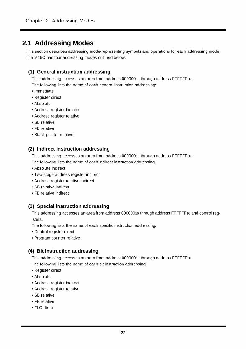
2.1 Addressing ModesThis section describes addressing mode-representing symbols and operations for each addressing mode.
The M16C has four addressing modes outlined below.
(1) General instruction addressingThis addressing accesses an area from address 00000016 through address FFFFFF16.
The following lists the name of each general instruction addressing:
• Immediate
• Register direct
• Absolute
• Address register indirect
• Address register relative
• SB relative
• FB relative
• Stack pointer relative
(2) Indirect instruction addressingThis addressing accesses an area from address 00000016 through address FFFFFF16.
The following lists the name of each indirect instruction addressing:
• Absolute indirect
• Two-stage address register indirect
• Address register relative indirect
• SB relative indirect
• FB relative indirect
(3) Special instruction addressingThis addressing accesses an area from address 00000016 through address FFFFFF16 and control reg-
isters.
The following lists the name of each specific instruction addressing:
• Control register direct
• Program counter relative
(4) Bit instruction addressingThis addressing accesses an area from address 00000016 through address FFFFFF16.
The following lists the name of each bit instruction addressing:
• Register direct
• Absolute
• Address register indirect
• Address register relative
• SB relative
• FB relative
• FLG direct

Chapter 2 Addressing Modes
23
2.2 Guide to This ChapterThe following shows how to read this chapter using an actual example.
(1) NameIndicates the name of addressing.
(2) SymbolRepresents the addressing mode.
(3) ExplanationDescribes the addressing operation and the effective address range.
(4) Operation diagramDiagrammatically explains the addressing operation.
(2)
(1)
(3)
(4)
Address register relative
dsp:8[A0]
dsp:8[A1]
dsp:16[A0]
dsp:16[A1]
dsp:24[A0]
dsp:24[A1]
The value indicated by displacement(dsp) plus the content of addressregister (A0/A1) added not includingthe sign bits constitutes the effectiveaddress to be operated on.
However, if the addition resulted inexceeding 0FFFFFF16, the bits abovebit 25 are ignored, and the addressreturns to 000000016.
Memory
addressA0 / A1
dspRegister
Chapter 2 Addressing Modes
24
#IMM
#IMM8
#IMM16
#IMM32
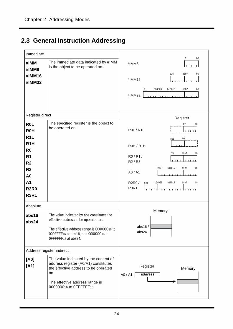
Immediate
The immediate data indicated by #IMMis the object to be operated on.
Register direct
R0L
R0H
R1L
R1H
R0
R1
R2
R3
A0
A1
R2R0
R3R1
The specified register is the object tobe operated on.
abs16 /
abs24
Absolute
abs16
abs24
[A0]
[A1]
Address register indirect
A0 / A1 address
Memory
2.3 General Instruction Addressing
Register Memory
The value indicated by abs constitutes theeffective address to be operated on.
The effective address range is 000000016 to000FFFF16 at abs16, and 000000016 to0FFFFFF16 at abs24.
The value indicated by the content ofaddress register (A0/A1) constitutesthe effective address to be operatedon.
The effective address range is000000016 to 0FFFFFF16.
#IMM8
#IMM16
#IMM32
b7 b0
b8b7 b0b16b15b24b23b31
b8b7 b0b15
b8b7 b0b15
b8b7 b0b16b15b24b23b31
b8b7 b0b16b15b23
b7 b0
b8b15
R0L / R1L
R0H / R1H
R0 / R1 /
R2 / R3
A0 / A1
R2R0 /
R3R1
Register

Chapter 2 Addressing Modes
25
address
address
AAA
Address register relative
dsp:8[A0]
dsp:8[A1]
dsp:16[A0]
dsp:16[A1]
dsp:24[A0]
dsp:24[A1]
dsp:8[SB]
dsp:16[SB]
SB relative
FB relative
dsp:8[FB]
dsp:16[FB]
The value indicated by displacement(dsp) plus the content of addressregister (A0/A1) added not includingthe sign bits constitutes the effectiveaddress to be operated on.
However, if the addition resulted inexceeding 0FFFFFF16, the bits abovebit 25 are ignored, and the addressreturns to 000000016.
address
dsp
dsp
FB
SB
dsp
The address indicated by the contentof frame base register (FB) plus thevalue indicated by displacement(dsp) added including the signbits constitutes the effective addressto be operated on.
However, if the addition resulted inexceeding 000000016- 0FFFFFF16,the bits above bit 25 are ignored, andthe address returns to 000000016 or0FFFFFF16.
Memory
addressA0 / A1
When the dsp value is negative
When the dsp value is positive
dspRegister
MemoryRegister
Memory
Register
address
The address indicated by the contentof static base register (SB) plus thevalue indicated by displacement(dsp) added not including the signbits constitutes the effective addressto be operated on.
However, if the addition resulted inexceeding 0FFFFFF16, the bits abovebit 25 are ignored, and the addressreturns to 000000016.

Chapter 2 Addressing Modes
26
dsp:8[SP]
Stack pointer relative
AAAdsp
dsp
SPRegister
MemoryWhen the dsp value is negative
When the dsp value is positive
address
The address indicated by the contentof stack pointer (SP) plus the valueindicated by displacement (dsp)added including the sign bits consti-tutes the effective address to beoperated on. The stack pointer (SP)here is the one indicated by the U flag.
However, if the addition resulted inexceeding 000000016- 0FFFFFF16, thebits above bit 25 are ignored, and theaddress returns to 000000016 or0FFFFFF16.
This addressing can be used in MOVinstruction.
address
Chapter 2 Addressing Modes
27
Absolute indirect
Two-stage address register indirect
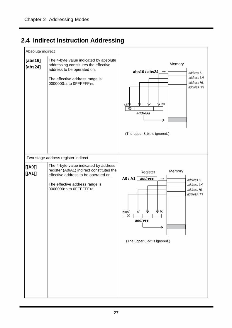
The 4-byte value indicated by addressregister (A0/A1) indirect constitutes theeffective address to be operated on.
The effective address range is000000016 to 0FFFFFF16.
The 4-byte value indicated by absoluteaddressing constitutes the effectiveaddress to be operated on.
The effective address range is000000016 to 0FFFFFF16.
2.4 Indirect Instruction Addressing
[abs16]
[abs24]
[[A0]]
[[A1]]
(The upper 8-bit is ignored.)
Memory
abs16 / abs24
address
b0b3100
MemoryRegister
A0 / A1
address
b0b3100
addressAAAAAAAAAAAAAAAAAA
address LLaddress LHaddress HLaddress HH
(The upper 8-bit is ignored.)
AAAAAAAAAAAAAAAAAA
address LLaddress LHaddress HLaddress HH

Chapter 2 Addressing Modes
28
SB relative indirect
[dsp:8[A0]]
[dsp:8[A1]]
[dsp:16[A0]]
[dsp:16[A1]]
[dsp:24[A0]]
[dsp:24[A1]]
dsp
[dsp:8[SB]]
[dsp:16[SB]]
SB address
A0 / A1
address
AAAAAAAAAAAAAAAAAA
address LLaddress LHaddress HLaddress HH
b0b31
address
dsp
address
address
b0b31
00
00
AAAAAAAAAAAAAAAAAA
address LLaddress LHaddress HLaddress HH
AAA
The 4-byte value indicated by SBrelative constitutes the effectiveaddress to be operated on.
The effective address range is000000016 to 0FFFFFF16.
The 4-byte value indicated byaddress register relative constitutesthe effective address to be operatedon.
The effective address range is000000016 to 0FFFFFF16.
Register
MemoryRegister
Memory
Address register relative indirect
(The upper 8-bit is ignored.)
(The upper 8-bit is ignored.)
Chapter 2 Addressing Modes
29
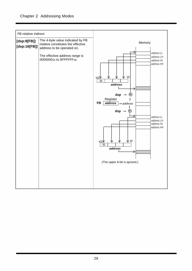
[dsp:8[FB]]
[dsp:16[FB]]
FB address
dsp
address
address
b0b3100
dsp
AAAAAAAAAAAAAAAAAAAAAAAA
address LLaddress LHaddress HLaddress HH
AAAA
AAAAAAAAAAAAAAAAAAAAAAAA
address LLaddress LHaddress HLaddress HH
(The upper 8-bit is ignored.)
FB relative indirect
The 4-byte value indicated by FBrelative constitutes the effectiveaddress to be operated on.
The effective address range is000000016 to 0FFFFFF16.
Register
Memory
address
b0b3100

Chapter 2 Addressing Modes
30
Control register direct
The specified control register is theobject to be operated on.
This addressing can be used in LDCand STC instructions.
If you specify SP, the stack pointerindicated by the U flag is the object tobe operated on.
RegisterINTB
ISP
USP
SB
FB
FLG
SVP
VCT
SVF
DMD0
DMD1
DCT0
DCT1
DRC0
DRC1
DMA0
DMA1
DSA0
DSA1
DRA0
DRA1
INTB
ISP
SP
SB
FB
FLG
SVP
VCT
SVF
DMD0
DMD1
DCT0
DCT1
DRC0
DRC1
DMA0
DMA1
DSA0
DSA1
DRA0
DRA1
2.5 Special Instruction Addressing
b0b7
b0b15
b0
b7
b7
b15
b0b15
b0b15
b0b15
b0b15
b0
b0
b0
b0
b0
b0
b0
b0
b23
b23
b23
b23
b23
b23
b23
b23
b23
b23
b23
b23
b23
b0
b0
b0
b0
b0
b0
Chapter 2 Addressing Modes
31
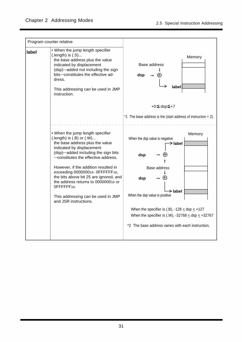
label
Program counter relative
• When the jump length specifier(.length) is (.S)...
the base address plus the valueindicated by displacement(dsp) added not including the signbits constitutes the effective ad-dress.
This addressing can be used in JMPinstruction.
• When the jump length specifier(.length) is (.B) or (.W)...
the base address plus the valueindicated by displacement(dsp) added including the sign bits constitutes the effective address.
However, if the addition resulted inexceeding 000000016- 0FFFFFF16,the bits above bit 25 are ignored, andthe address returns to 000000016 or0FFFFFF16.
This addressing can be used in JMPand JSR instructions.
2.5 Special Instruction Addressing
+0 dsp +7
Memory
label
Base address
dsp
dsp
AAAdsp
label
label
Memory
Base address
When the dsp value is positive
When the dsp value is negative
*1 The base address is the (start address of instruction + 2).
*2 The base address varies with each instruction.
When the specifier is (.B), -128 < dsp < +127
When the specifier is (.W), -32768 < dsp < +32767
Chapter 2 Addressing Modes
32
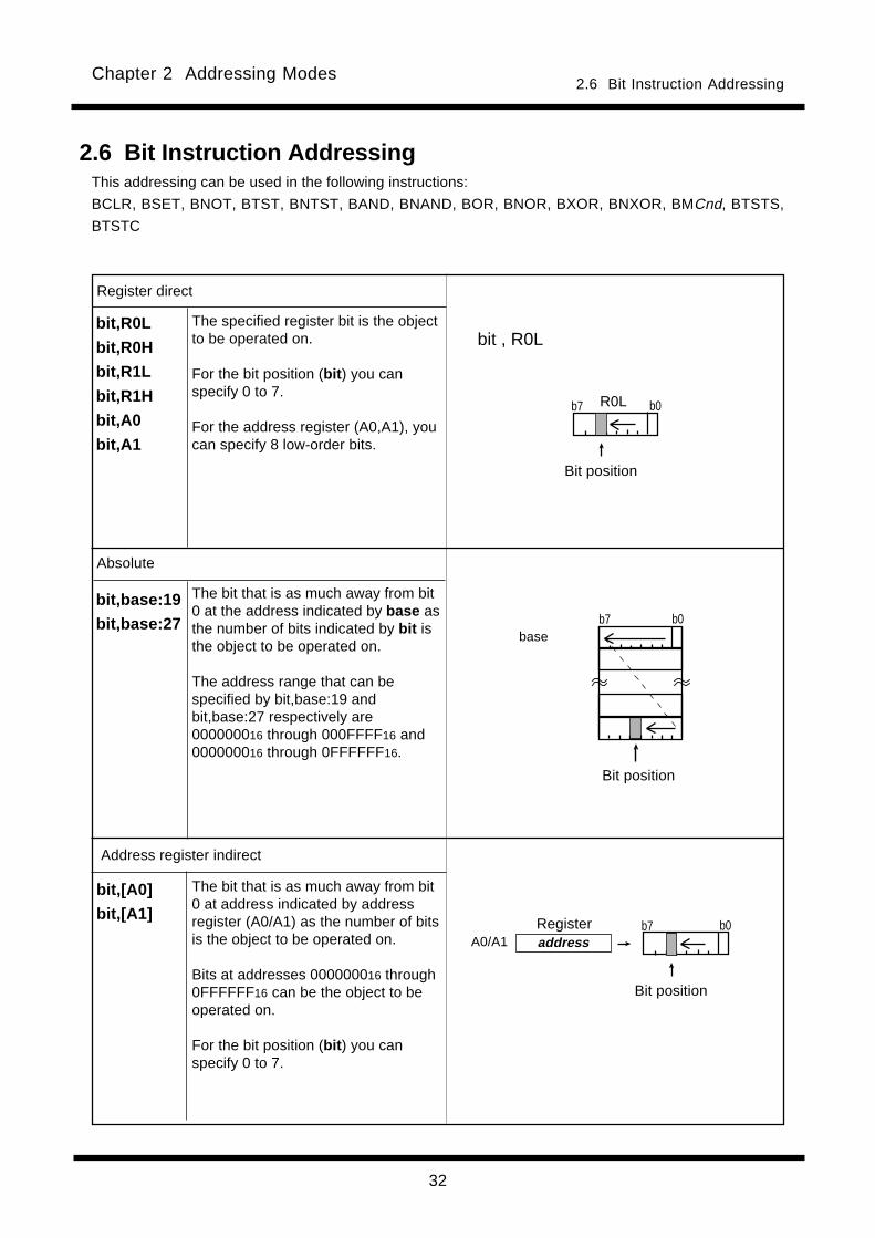
The specified register bit is the objectto be operated on.
For the bit position (bit ) you canspecify 0 to 7.
For the address register (A0,A1), youcan specify 8 low-order bits.
Register direct
Address register indirect
The bit that is as much away from bit0 at address indicated by addressregister (A0/A1) as the number of bitsis the object to be operated on.
Bits at addresses 000000016 through0FFFFFF16 can be the object to beoperated on.
For the bit position (bit ) you canspecify 0 to 7.
bit,[A0]
bit,[A1]
bit , R0L
Absolute
The bit that is as much away from bit0 at the address indicated by base asthe number of bits indicated by bit isthe object to be operated on.
The address range that can bespecified by bit,base:19 andbit,base:27 respectively are000000016 through 000FFFF16 and000000016 through 0FFFFFF16.
b7 b0base
Bit position
Bit position
2.6 Bit Instruction Addressing
2.6 Bit Instruction AddressingThis addressing can be used in the following instructions:
BCLR, BSET, BNOT, BTST, BNTST, BAND, BNAND, BOR, BNOR, BXOR, BNXOR, BMCnd, BTSTS,
BTSTC
bit,R0L
bit,R0H
bit,R1L
bit,R1H
bit,A0
bit,A1
b0b7
bit,base:19
bit,base:27
R0L
Bit position
b0b7addressRegister
A0/A1
Chapter 2 Addressing Modes
33
base
address
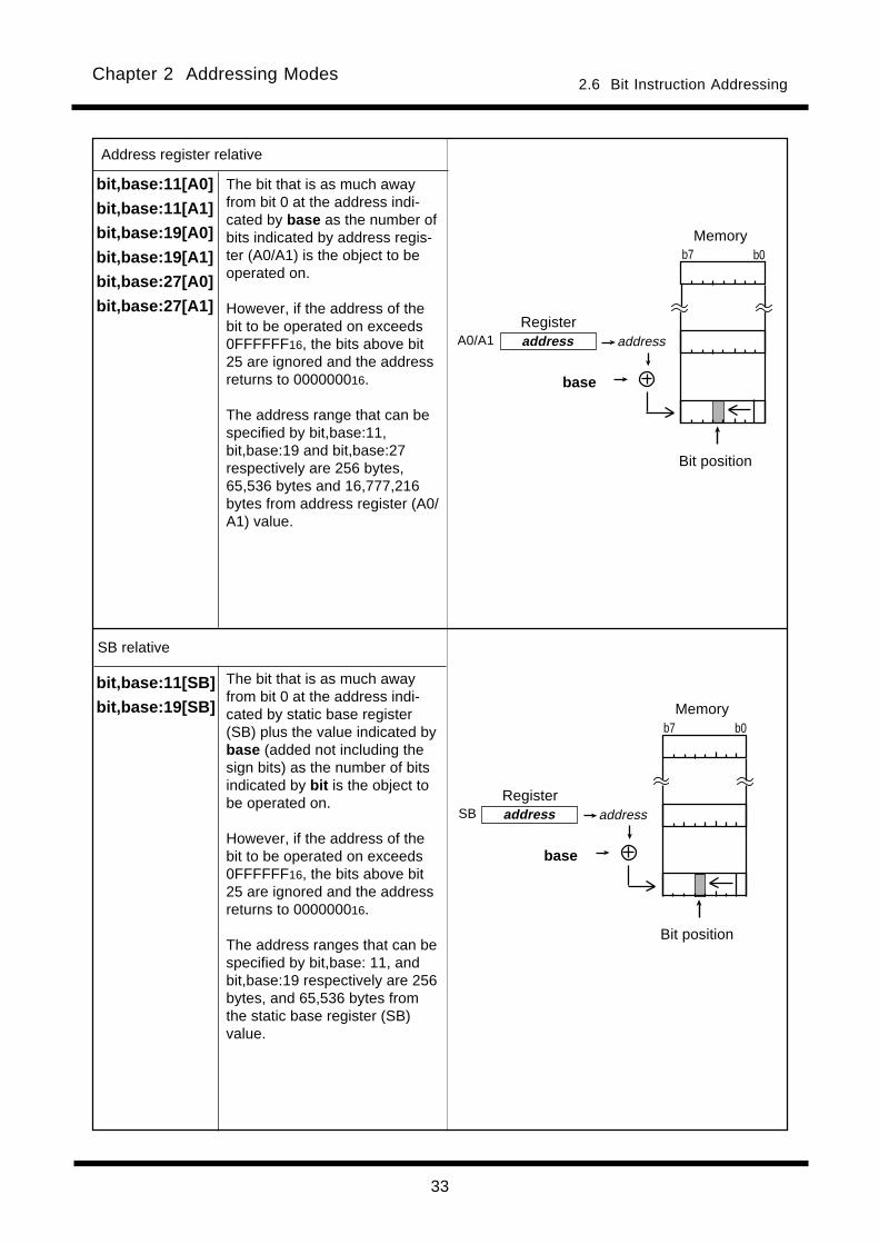
Address register relative
bit,base:11[A0]
bit,base:11[A1]
bit,base:19[A0]
bit,base:19[A1]
bit,base:27[A0]
bit,base:27[A1]
SB relative
bit,base:11[SB]
bit,base:19[SB]b7 b0
Memory
addressRegister
SB
Bit position
2.6 Bit Instruction Addressing
The bit that is as much awayfrom bit 0 at the address indi-cated by base as the number ofbits indicated by address regis-ter (A0/A1) is the object to beoperated on.
However, if the address of thebit to be operated on exceeds0FFFFFF16, the bits above bit25 are ignored and the addressreturns to 000000016.
The address range that can bespecified by bit,base:11,bit,base:19 and bit,base:27respectively are 256 bytes,65,536 bytes and 16,777,216bytes from address register (A0/A1) value.
The bit that is as much awayfrom bit 0 at the address indi-cated by static base register(SB) plus the value indicated bybase (added not including thesign bits) as the number of bitsindicated by bit is the object tobe operated on.
However, if the address of thebit to be operated on exceeds0FFFFFF16, the bits above bit25 are ignored and the addressreturns to 000000016.
The address ranges that can bespecified by bit,base: 11, andbit,base:19 respectively are 256bytes, and 65,536 bytes fromthe static base register (SB)value.
base
address
b7 b0Memory
addressRegister
A0/A1
Bit position

34
Chapter 2 Addressing Modes
address
FB relative
bit,base:11[FB]
bit,base:19[FB]
FB addressRegister
base
base
If the base value is negative
If the base value is positive
Memory
Bit position
FLG direct
U
I
O
B
S
Z
D
C
U I O B S Z D C
b0b7
FLG
Register
2.6 Bit Instruction Addressing
The specified flag is the object tobe operated on.
This addressing can be used inFCLR and FSET instructions.
The bit that is as much awayfrom bit 0 at the address indi-cated by frame base register(FB) plus the value indicated bybase (added including the signbit) as the number of bits indi-cated by bit is the object to beoperated on.
However, if the address of thebit to be operated on exceeds000000016-0FFFFFF16, the bitsabove bit 25 are ignored and theaddress returns to 000000016 or0FFFFFF16.
The address range that can bespecified by bit,base:11 andbit,base:19 are 128 bytes towardlower addresses or 127 bytestoward higher addresses fromthe frame base register (FB)value, and 32,768 bytes towardlower addresses or 32,767 bytestoward higher addresses, re-spectively.
(Bit position)

35
Chapter 2 Addressing Modes
b15 b7b8 b012345678123456781234567812345678
b16b23
b7 b0123456781234567812345678
Read
b15 b7b8 b012345678123456781234567812345678
Write
b15 b7b8 b0123456781234567812345678
b16b23
0016
Zero-expanded
00160016
1234567123456712345671234567
Operation
b15 b7b8 b0123456781234567812345678
123456712345671234567
b16b23
0016
0016
Write
b15 b7b8 b012345678123456781234567812345678
12345678123456781234567812345678
b16b230016
Ignored
• Read
The 8 low-order bits are read. The flags change
states depending on the result of 8-bit operation.
• Write
[ Transfer instruction ]
src is zero-expanded to 16 bits and saved to the
low-order 16-bit. In this case, the 8 high-order bits
become 0. The flags change states depending on
the result of 16-bit transfer data.
[ Operating instructions ]
src is zero-expanded to perform operation in 16-bit.
In this case, the 8 high-order bits become 0. The
flags change states depending on the result of 16-
bit operation.
When (.B) is specified for the size specifier (.size)
2.7 Read and write operations with 24-bit registersThis section describes operation when 24 bits register(A0, A1) is src or dest for each size specifier (.size/.B
.W .L).
Zero-expanded
b15 b7b8 b0
2.7 Read and write operations with 24-bit registers
A0/A1
A0/A1
A0/A1
A0/A1

36
Chapter 2 Addressing Modes
Read
Write
Zero-expanded
12345678123456781234567812345678
123456712345671234567
123456712345671234567
1234567123456712345671234567
123456712345671234567
12345678123456781234567812345678
12345678123456781234567812345678
123456781234567812345678
123456781234567812345678
123456781234567812345678
123456781234567812345678
b31
12345678123456781234567812345678
12345678123456781234567812345678
12345678123456781234567812345678
12345678123456781234567812345678
12345678123456781234567812345678
12345678123456781234567812345678
1234567123456712345671234567
123456781234567812345678
123456781234567812345678
123456712345671234567
0016
0016
b24
• Read
The low order 16-bit are read. The flags change
states depending on the result of 16-bit operation.
• Write
Write to the low order 16-bit. In this case, the 8
high-order bits become 0. The flags change states
depending on the result of 16-bit transfer data.
When (.W) is specified for the size specifier (.size)
• Read
32 bits are read out after being zero-extended.
The flag varies depending on the result of a 32-bit
operation.
• Write
The low-order 24-bit is written, with the 8 high-
order bit ignored. The flag varies depending on
the result of a 32-bit operation (not the value of the
24-bit register).
Example: MOV.L#80000000h,A0
Flag status after execution
S flag = 1 (The MSB is bit 31.)
Z flag = 0 (Set to 1 when all of 32
bits are 0s.)
The value of A0 after executing the above instruc-
tion becomes 00000016. However, since operation
is performed on 32-bit data, the S flag is set to 1
and the Z flag is cleared to 0.
When (.L) is specified for the size specifier (.size)
Read
Write
b15 b7b8 b0b16b23
b15 b7b8 b0
b15 b7b8 b0
b15 b7b8 b0b16b23
b15 b7b8 b0b16b23
b15 b7b8 b0b16b23
b31 b24 b15 b7b8 b0b16b23
b31 b24 b15 b7b8 b0b16b23
A0/A1
A0/A1
A0/A1
A0/A1
2.7 Read and write operations with 24-bit registers

Chapter 3
Functions
3.1 Guide to This Chapter
3.2 Functions
3.3 Index Instructions
38
3.1 Guide to This ChapterChapter 3 Functions
115
OR
[ Function ]
[ Description Example ]
[ Selectable src/dest ]
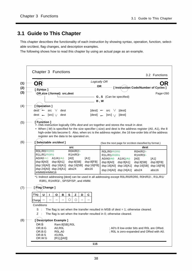
[ Syntax ]OR.size (:format) src,dest
3.1 Guide to This Chapter
This chapter describes the functionality of each instruction by showing syntax, operation, function, select-
able src/dest, flag changes, and description examples.
The following shows how to read this chapter by using an actual page as an example.
U I O B S Z D C
OR
G , S (Can be specified)
B , W
[ Flag Change ]
(2)
(6)
(7)
(5)
(4)
(3)
(1)
(8)
[ Instruction Code/Number of Cycles ]
Page=260
3.2 FunctionsChapter 3 Functions
(See the next page for src/dest classified by format.)
Conditions
S : The flag is set when the transfer resulted in MSB of dest = 1; otherwise cleared.
Z : The flag is set when the transfer resulted in 0; otherwise cleared.
Flag
Change
OR
Logically OR
• This instruction logically ORs dest and src together and stores the result in dest.• When (.W) is specified for the size specifier (.size) and dest is the address register (A0, A1), the 8
high-order bits become 0. Also, when src is the address register, the 16 low-order bits of the addressregister are the data to be operated on.
[ Operation ]
dest src dest [dest] src [dest]
dest [src] dest [dest] [src] [dest]
src destR0L/R0/R2R0 R0H/R2/-R1L/R1/R3R1 R1H/R3/-A0/A0/A0 A1/A1/A1 [A0] [A1]dsp:8[A0] dsp:8[A1] dsp:8[SB] dsp:8[FB]dsp:16[A0] dsp:16[A1] dsp:16[SB] dsp:16[FB]dsp:24[A0] dsp:24[A1] abs24 abs16#IMM8/#IMM16
R0L/R0/R2R0 R0H/R2/-R1L/R1/R3R1 R1H/R3/-A0/A0/A0 A1/A1/A1 [A0] [A1]dsp:8[A0] dsp:8[A1] dsp:8[SB] dsp:8[FB]dsp:16[A0] dsp:16[A1] dsp:16[SB] dsp:16[FB]
dsp:24[A0] dsp:24[A1] abs24 abs16
*1 Indirect addressing [dest] can be used in all addressing except R0L/R0/R2R0, R0H/R2/-, R1L/R1/R3R1, R1H/R3/-, SP/SP/SP, and #IMM.
OR.B Ram:8[SB],R0LOR.B:G A0,R0L ; A0's 8 low-order bits and R0L are ORed.OR.B:G R0L,A0 ; R0L is zero-expanded and ORed with A0.OR.B:S #3,R0LOR.W:G [R1],[[A0]]
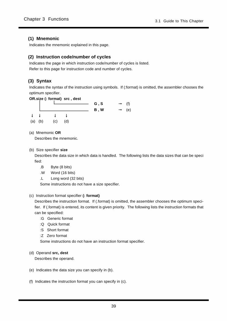
39
3.1 Guide to This ChapterChapter 3 Functions
(1) MnemonicIndicates the mnemonic explained in this page.
(2) Instruction code/number of cyclesIndicates the page in which instruction code/number of cycles is listed.
Refer to this page for instruction code and number of cycles.
(3) SyntaxIndicates the syntax of the instruction using symbols. If (:format) is omitted, the assembler chooses the
optimum specifier.
OR.size (: format) src , destG , S (f)
B , W (e)
(a) (b) (c) (d)
(a) Mnemonic OR
Describes the mnemonic.
(b) Size specifier size
Describes the data size in which data is handled. The following lists the data sizes that can be speci
fied:
.B Byte (8 bits)
.W Word (16 bits)
.L Long word (32 bits)
Some instructions do not have a size specifier.
(c) Instruction format specifier (: format)
Describes the instruction format. If (.format) is omitted, the assembler chooses the optimum speci-
fier. If (.format) is entered, its content is given priority. The following lists the instruction formats that
can be specified:
:G Generic format
:Q Quick format
:S Short format
:Z Zero format
Some instructions do not have an instruction format specifier.
(d) Operand src, dest
Describes the operand.
(e) Indicates the data size you can specify in (b).
(f) Indicates the instruction format you can specify in (c).

40
3.1 Guide to This ChapterChapter 3 Functions
[ Operation ]
dest src dest [dest] src [dest]
dest [src] dest [dest] [src] [dest]
115
OR
[ Function ]
[ Syntax ]OR.size (:format) src,dest
OR
G , S (Can be specified)
W , B
(2)
(5)
(4)
(3)
(1)[ Instruction Code/Number of Cycles ]
Page=260
3.2 FunctionsChapter 3 Functions
OR
Logically OR
• This instruction logically ORs dest and src together and stores the result in dest.• When (.W) is specified for the size specifier (.size) and dest is the address register (A0, A1), the 8
high-order bits become 0. Also, when src is the address register, the 16 low-order bits of the addressregister are the data to be operated on.
[ Description Example ](8)OR.B Ram:8[SB],R0LOR.B:G A0,R0L ; A0' s 8 low-order bits and R0L are ORed.OR.B:G R0L,A0 ; R0L is zero-expanded and ORed with A0.OR.B:S #3,R0LOR.W:G [R1],[[A0]]
U I O B S Z D C
[ Flag Change ](7)
Conditions
S : The flag is set when the transfer resulted in MSB of dest = 1; otherwise cleared.
Z : The flag is set when the transfer resulted in 0; otherwise cleared.
Flag
Change
[ Selectable src/dest ](6) (See the next page for src/dest classified by format.)
src destR0L/R0/R2R0 R0H/R2/-R1L/R1/R3R1 R1H/R3/-A0/A0/A0 A1/A1/A1 [A0] [A1]dsp:8[A0] dsp:8[A1] dsp:8[SB] dsp:8[FB]dsp:16[A0] dsp:16[A1] dsp:16[SB] dsp:16[FB]dsp:24[A0] dsp:24[A1] abs24 abs16#IMM8/#IMM16
R0L/R0/R2R0 R0H/R2/-R1L/R1/R3R1 R1H/R3/-A0/A0/A0 A1/A1/A1 [A0] [A1]dsp:8[A0] dsp:8[A1] dsp:8[SB] dsp:8[FB]dsp:16[A0] dsp:16[A1] dsp:16[SB] dsp:16[FB]
dsp:24[A0] dsp:24[A1] abs24 abs16
*1 Indirect addressing [src]and[dest] can be used in all addressing except R0L/R0/R2R0, R0H/R2/-, R1L/R1/R3R1, R1H/R3/-, SP/SP/SP, and #IMM.
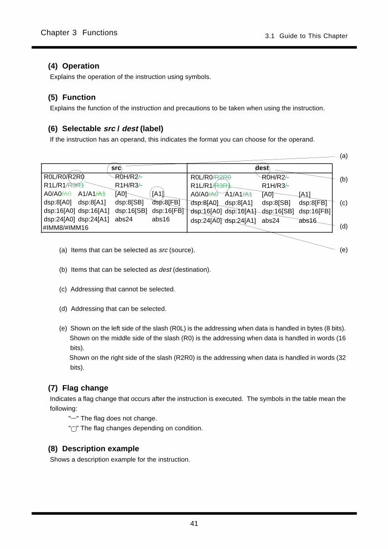
41
3.1 Guide to This ChapterChapter 3 Functions
R0L/R0/R2R0 R0H/R2/-R1L/R1/R3R1 R1H/R3/-A0/A0/A0 A1/A1/A1 [A0] [A1]dsp:8[A0] dsp:8[A1] dsp:8[SB] dsp:8[FB]dsp:16[A0] dsp:16[A1] dsp:16[SB] dsp:16[FB]dsp:24[A0] dsp:24[A1] abs24 abs16
src destR0L/R0/R2R0 R0H/R2/-R1L/R1/R3R1 R1H/R3/-A0/A0/A0 A1/A1/A1 [A0] [A1]dsp:8[A0] dsp:8[A1] dsp:8[SB] dsp:8[FB]dsp:16[A0] dsp:16[A1] dsp:16[SB] dsp:16[FB]dsp:24[A0] dsp:24[A1] abs24 abs16#IMM8/#IMM16
(4) OperationExplains the operation of the instruction using symbols.
(5) FunctionExplains the function of the instruction and precautions to be taken when using the instruction.
(6) Selectable src / dest (label)If the instruction has an operand, this indicates the format you can choose for the operand.
(a) Items that can be selected as src (source).
(b) Items that can be selected as dest (destination).
(c) Addressing that cannot be selected.
(d) Addressing that can be selected.
(e) Shown on the left side of the slash (R0L) is the addressing when data is handled in bytes (8 bits).
Shown on the middle side of the slash (R0) is the addressing when data is handled in words (16
bits).
Shown on the right side of the slash (R2R0) is the addressing when data is handled in words (32
bits).
(7) Flag changeIndicates a flag change that occurs after the instruction is executed. The symbols in the table mean the
following:
" " The flag does not change.
" " The flag changes depending on condition.
(8) Description exampleShows a description example for the instruction.
(a)
(b)
(c)
(d)
(e)
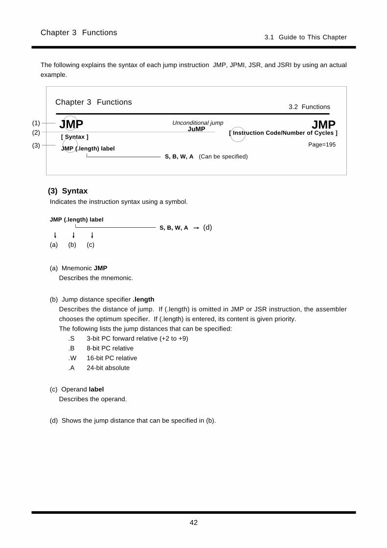
42
3.1 Guide to This ChapterChapter 3 Functions
The following explains the syntax of each jump instruction JMP, JPMI, JSR, and JSRI by using an actual
example.
(3) SyntaxIndicates the instruction syntax using a symbol.
(a) (b) (c)
(a) Mnemonic JMP
Describes the mnemonic.
(b) Jump distance specifier .length
Describes the distance of jump. If (.length) is omitted in JMP or JSR instruction, the assembler
chooses the optimum specifier. If (.length) is entered, its content is given priority.
The following lists the jump distances that can be specified:
.S 3-bit PC forward relative (+2 to +9)
.B 8-bit PC relative
.W 16-bit PC relative
.A 24-bit absolute
(c) Operand label
Describes the operand.
(d) Shows the jump distance that can be specified in (b).
JuMP Unconditional jump
JMP (.length) labelS, B, W, A (d)
[ Syntax ]
JMP (.length) label
JMP
S, B, W, A (Can be specified)
(2)
(3)
(1)
3.2 FunctionsChapter 3 Functions
JMP[ Instruction Code/Number of Cycles ]
Page=195
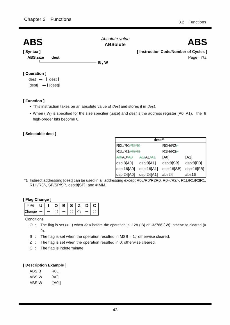
43
3.2 FunctionsChapter 3 Functions
Absolute valueABSolute
[ Syntax ]
ABS.size dest
ABS.B R0L
ABS.W [A0]
ABS.W [[A0]]
[ Selectable dest ]
ABS
[ Function ]• This instruction takes on an absolute value of dest and stores it in dest.
• When (.W) is specified for the size specifier (.size) and dest is the address register (A0, A1), the 8
high-oreder bits become 0.
[ Description Example ]
ABS
Conditions
O : The flag is set (= 1) when dest before the operation is -128 (.B) or -32768 (.W); otherwise cleared (=
0).
S : The flag is set when the operation resulted in MSB = 1; otherwise cleared.
Z : The flag is set when the operation resulted in 0; otherwise cleared.
C : The flag is indeterminate.
[ Flag Change ]
[ Operation ]
dest dest
[dest] [dest]
B , W
U I O B S Z D C
174
[ Instruction Code/Number of Cycles ]
Page=
Flag
Change
dest* 1
R0L/R0/R2R0 R0H/R2/-
R1L/R1/R3R1 R1H/R3/-
A0/A0/A0 A1/A1/A1 [A0] [A1]
dsp:8[A0] dsp:8[A1] dsp:8[SB] dsp:8[FB]
dsp:16[A0] dsp:16[A1] dsp:16[SB] dsp:16[FB]
dsp:24[A0] dsp:24[A1] abs24 abs16
*1 Indirect addressing [dest] can be used in all addressing except R0L/R0/R2R0, R0H/R2/-, R1L/R1/R3R1,R1H/R3/-, SP/SP/SP, dsp:8[SP], and #IMM.

44
3.2 FunctionsChapter 3 Functions
[ Instruction Code/Number of Cycles ]
Page=
Add with carryADdition with Carry
[ Selectable src/dest ]
[ Syntax ]
ADC.size src,dest
ADCADC
[ Function ]
[ Description Example ]
B , W
[ Operation ]
dest src + dest + C
[ Flag Change ]
• This instruction adds dest, src and C flag together and stores the result in dest.• When (.B) is specified for the size specifier (.size) and dest is the address register (A0, A1), src is zero-
extended to perform operation in 16 bits. In this case, the 8 high-oreder bits become 0. Also, when srcis the address register, the 8 low-order bits of the address register are used as data to be operated on.
• When (.W) is specified for the size specifier (.size) and dest is the address register, the 8 high-orderbits become 0. Also, when src is the address register, the 16 low-order bits of the address register arethe data to be operated on.
; A0's 8 low-order bits and R0L are added.
; R0L is zero-expanded and added with A0.
U I O B S Z D C
*1 When you specify (.B) for the size specifier (.size), you cannot choose A0 and/or A1 for src and destsimultaneously.
Conditions
O : The flag is set when a signed operation resulted in exceeding +32767 (.W) or - 32768 (.W) or
+127 (.B) or -128 (.B); otherwise cleared.
S : The flag is set when the operation resulted in MSB = 1; otherwise cleared.
Z : The flag is set when the operation resulted in 0; otherwise cleared.
C : The flag is set when an unsigned operation resulted in exceeding +65535 (.W) or +255 (.B);
otherwise cleared.
Change
ADC.B #2,R0L
ADC.W A0,R0
ADC.B A0,R0L
ADC.B R0L,A0
ADC.W R1,[A1]
174
Flag
src dest
R0L/R0/R2R0 R0H/R2/-
R1L/R1/R3R1 R1H/R3/-
A0/A0/A0*1 A1/A1/A1*1 [A0] [A1]
dsp:8[A0] dsp:8[A1] dsp:8[SB] dsp:8[FB]
dsp:16[A0] dsp:16[A1] dsp:16[SB] dsp:16[FB]
dsp:24[A0] dsp:24[A1] abs24 abs16
#IMM8/#IMM16
R0L/R0/R2R0 R0H/R2/-
R1L/R1/R3R1 R1H/R3/-
A0/A0/A0*1 A1/A1/A1*1 [A0] [A1]
dsp:8[A0] dsp:8[A1] dsp:8[SB] dsp:8[FB]
dsp:16[A0] dsp:16[A1] dsp:16[SB] dsp:16[FB]
dsp:24[A0] dsp:24[A1] abs24 abs16
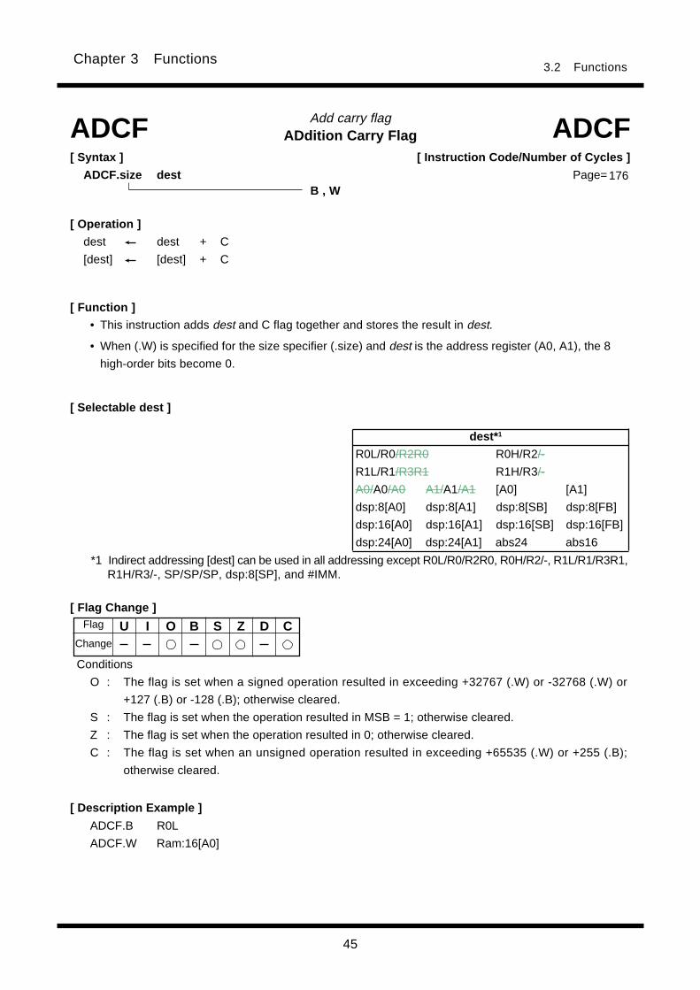
45
3.2 FunctionsChapter 3 Functions
Add carry flagADdition Carry Flag
[ Selectable dest ]
ADCF ADCF
[ Function ]
[ Flag Change ]
Conditions
O : The flag is set when a signed operation resulted in exceeding +32767 (.W) or -32768 (.W) or
+127 (.B) or -128 (.B); otherwise cleared.
S : The flag is set when the operation resulted in MSB = 1; otherwise cleared.
Z : The flag is set when the operation resulted in 0; otherwise cleared.
C : The flag is set when an unsigned operation resulted in exceeding +65535 (.W) or +255 (.B);
otherwise cleared.
[ Description Example ]
ADCF.B R0L
ADCF.W Ram:16[A0]
B , W
[ Syntax ]
ADCF.size dest
[ Operation ]
dest dest + C
[dest] [dest] + C
U I O B S Z D C
• This instruction adds dest and C flag together and stores the result in dest.
• When (.W) is specified for the size specifier (.size) and dest is the address register (A0, A1), the 8
high-order bits become 0.
176
[ Instruction Code/Number of Cycles ]
Page=
Change
Flag
dest* 1
R0L/R0/R2R0 R0H/R2/-
R1L/R1/R3R1 R1H/R3/-
A0/A0/A0 A1/A1/A1 [A0] [A1]
dsp:8[A0] dsp:8[A1] dsp:8[SB] dsp:8[FB]
dsp:16[A0] dsp:16[A1] dsp:16[SB] dsp:16[FB]
dsp:24[A0] dsp:24[A1] abs24 abs16
*1 Indirect addressing [dest] can be used in all addressing except R0L/R0/R2R0, R0H/R2/-, R1L/R1/R3R1,R1H/R3/-, SP/SP/SP, dsp:8[SP], and #IMM.
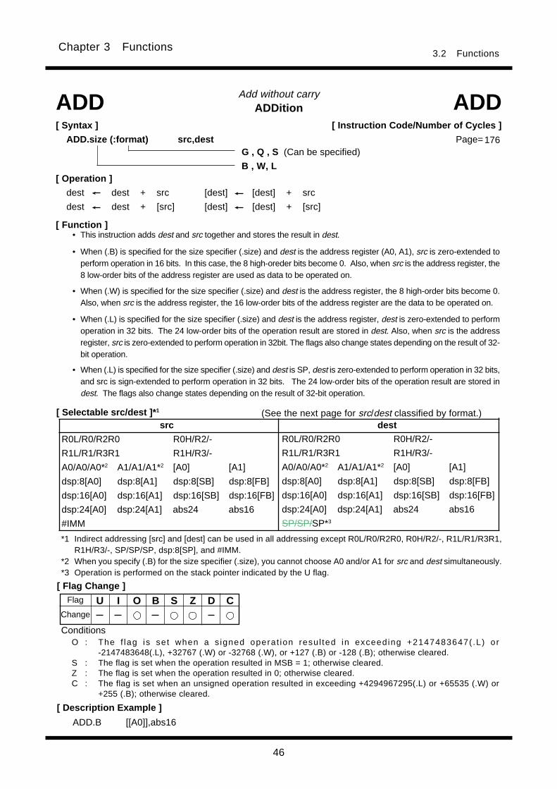
46
3.2 FunctionsChapter 3 Functions
Add without carryADDitionADD ADD
[ Syntax ]
ADD.size (:format) src,dest
ADD.B [[A0]],abs16
G , Q , S (Can be specified)
B , W, L[ Operation ]
dest dest + src [dest] [dest] + src
dest dest + [src] [dest] [dest] + [src]
ConditionsO : The f lag is set when a s igned operat ion resu l ted in exceeding +2147483647( .L) or
-2147483648(.L), +32767 (.W) or -32768 (.W), or +127 (.B) or -128 (.B); otherwise cleared.S : The flag is set when the operation resulted in MSB = 1; otherwise cleared.Z : The flag is set when the operation resulted in 0; otherwise cleared.C : The flag is set when an unsigned operation resulted in exceeding +4294967295(.L) or +65535 (.W) or
+255 (.B); otherwise cleared.
[ Description Example ]
176
[ Instruction Code/Number of Cycles ]
Page=
[ Function ]• This instruction adds dest and src together and stores the result in dest.
• When (.B) is specified for the size specifier (.size) and dest is the address register (A0, A1), src is zero-extended toperform operation in 16 bits. In this case, the 8 high-oreder bits become 0. Also, when src is the address register, the8 low-order bits of the address register are used as data to be operated on.
• When (.W) is specified for the size specifier (.size) and dest is the address register, the 8 high-order bits become 0.Also, when src is the address register, the 16 low-order bits of the address register are the data to be operated on.
• When (.L) is specified for the size specifier (.size) and dest is the address register, dest is zero-extended to performoperation in 32 bits. The 24 low-order bits of the operation result are stored in dest. Also, when src is the addressregister, src is zero-extended to perform operation in 32bit. The flags also change states depending on the result of 32-bit operation.
• When (.L) is specified for the size specifier (.size) and dest is SP, dest is zero-extended to perform operation in 32 bits,and src is sign-extended to perform operation in 32 bits. The 24 low-order bits of the operation result are stored indest. The flags also change states depending on the result of 32-bit operation.
[ Selectable src/dest ]* 1
*1 Indirect addressing [src] and [dest] can be used in all addressing except R0L/R0/R2R0, R0H/R2/-, R1L/R1/R3R1,R1H/R3/-, SP/SP/SP, dsp:8[SP], and #IMM.
*2 When you specify (.B) for the size specifier (.size), you cannot choose A0 and/or A1 for src and dest simultaneously.*3 Operation is performed on the stack pointer indicated by the U flag.
(See the next page for src/dest classified by format.)src dest
R0L/R0/R2R0 R0H/R2/-
R1L/R1/R3R1 R1H/R3/-
A0/A0/A0*2 A1/A1/A1*2 [A0] [A1]
dsp:8[A0] dsp:8[A1] dsp:8[SB] dsp:8[FB]
dsp:16[A0] dsp:16[A1] dsp:16[SB] dsp:16[FB]
dsp:24[A0] dsp:24[A1] abs24 abs16
#IMM
R0L/R0/R2R0 R0H/R2/-
R1L/R1/R3R1 R1H/R3/-
A0/A0/A0*2 A1/A1/A1*2 [A0] [A1]
dsp:8[A0] dsp:8[A1] dsp:8[SB] dsp:8[FB]
dsp:16[A0] dsp:16[A1] dsp:16[SB] dsp:16[FB]
dsp:24[A0] dsp:24[A1] abs24 abs16
SP/SP/SP*3
[ Flag Change ]
U I O B S Z D CChange
Flag
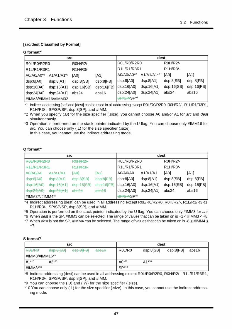
47
3.2 FunctionsChapter 3 Functions
[src/dest Classified by Format]
G format* 1
*1 Indirect addressing [src] and [dest] can be used in all addressing except R0L/R0/R2R0, R0H/R2/-, R1L/R1/R3R1,R1H/R3/-, SP/SP/SP, dsp:8[SP], and #IMM.
*2 When you specify (.B) for the size specifier (.size), you cannot choose A0 and/or A1 for src and destsimultaneously.
*3 Operation is performed on the stack pointer indicated by the U flag. You can choose only #IMM16 forsrc. You can choose only (.L) for the size specifier (.size).In this case, you cannot use the indirect addressing mode.
*8 Indirect addressing [dest] can be used in all addressing except R0L/R0/R2R0, R0H/R2/-, R1L/R1/R3R1,R1H/R3/-, SP/SP/SP, dsp:8[SP], and #IMM.
*9 You can choose the (.B) and (.W) for the size specifier (.size).*10 You can choose only (.L) for the size specifier (.size). In this case, you cannot use the indirect address-
ing mode.
*4 Indirect addressing [dest] can be used in all addressing except R0L/R0/R2R0, R0H/R2/-, R1L/R1/R3R1,R1H/R3/-, SP/SP/SP, dsp:8[SP], and #IMM.
*5 Operation is performed on the stack pointer indicated by the U flag. You can choose only #IMM3 for src.*6 When dest is the SP, #IMM3 can be selected. The range of values that can be taken on is +1 < #IMM3 < +8.*7 When dest is not the SP, #IMM4 can be selected. The range of values that can be taken on is -8 < #IMM4 <
+7.
S format *8
Q format* 4
src dest
R0L/R0 dsp:8[SB] dsp:8[FB] abs16 R0L/R0 dsp:8[SB] dsp:8[FB] abs16
#IMM8/#IMM16*9
#1*10 #2*10 A0*10 A1*10
#IMM8*10 SP*10
src dest
R0L/R0/R2R0 R0H/R2/-
R1L/R1/R3R1 R1H/R3/-
A0/A0/A0*2 A1/A1/A1*2 [A0] [A1]
dsp:8[A0] dsp:8[A1] dsp:8[SB] dsp:8[FB]
dsp:16[A0] dsp:16[A1] dsp:16[SB] dsp:16[FB]
dsp:24[A0] dsp:24[A1] abs24 abs16
#IMM8/#IMM16/#IMM32
R0L/R0/R2R0 R0H/R2/-
R1L/R1/R3R1 R1H/R3/-
A0/A0/A0*2 A1/A1/A1*2 [A0] [A1]
dsp:8[A0] dsp:8[A1] dsp:8[SB] dsp:8[FB]
dsp:16[A0] dsp:16[A1] dsp:16[SB] dsp:16[FB]
dsp:24[A0] dsp:24[A1] abs24 abs16
SP/SP/SP*3
src dest
R0L/R0/R2R0 R0H/R2/-
R1L/R1/R3R1 R1H/R3/-
A0/A0/A0 A1/A1/A1 [A0] [A1]
dsp:8[A0] dsp:8[A1] dsp:8[SB] dsp:8[FB]
dsp:16[A0] dsp:16[A1] dsp:16[SB] dsp:16[FB]
dsp:24[A0] dsp:24[A1] abs24 abs16
#IMM3*6/#IMM4*7
R0L/R0/R2R0 R0H/R2/-
R1L/R1/R3R1 R1H/R3/-
A0/A0/A0 A1/A1/A1 [A0] [A1]
dsp:8[A0] dsp:8[A1] dsp:8[SB] dsp:8[FB]
dsp:16[A0] dsp:16[A1] dsp:16[SB] dsp:16[FB]
dsp:24[A0] dsp:24[A1] abs24 abs16
SP/SP/SP*5

48
3.2 FunctionsChapter 3 Functions
Add extend sign without carryADDition eXtend signADDX ADDX
[ Syntax ]
ADDX src,dest
[ Flag Change ]
ADDX R0L,A0
ADDX RAM:8[SB],R2R0
ADDX [A0],A1
[ Operation ]
dest dest + EXTS(src) [dest] [dest] + EXTS(src)
dest dest + EXTS([src]) [dest] [dest] + EXTS([src])
Conditions
O : The flag is set when a signed operation resulted in exceeding +2147483647(.L) or
-2147483648(.L); otherwise cleared.
S : The flag is set when the operation resulted in MSB = 1; otherwise cleared.
Z : The flag is set when the operation resulted in 0; otherwise cleared.
C : The flag is set when an unsigned operation resulted in exceeding +4294967295(.L); otherwise
cleared.
[ Description Example ]
U I O B S Z D C
[ Instruction Code/Number of Cycles ]
Page=
Change
Flag
[ Function ]• Sign-extend the 8-bit src to 32 bits which are added to the 32-bit dest, and the result is stored in dest.
• When dest is the address register(A0, A1) , dest is zero-extended to perform operation in 32 bits. The24 low-order bits of the operation result are stored in dest. The flags also change states depending onthe result of 32-bit operation. Also, when src is the address register, src is zero-extended to performoperation in 8 low-order bits.
[ Selectable src/dest ]* 1
*1 Indirect addressing [src] and [dest] can be used in all addressing except R0L/R0/R2R0, R0H/R2/-, R1L/R1/R3R1, R1H/R3/-, SP/SP/SP, dsp:8[SP], and #IMM.
src dest
R0L/R0/R2R0 R0H/R2/-
R1L/R1/R3R1 R1H/R3/-
A0/A0/A0 A1/A1/A1 [A0] [A1]
dsp:8[A0] dsp:8[A1] dsp:8[SB] dsp:8[FB]
dsp:16[A0] dsp:16[A1] dsp:16[SB] dsp:16[FB]
dsp:24[A0] dsp:24[A1] abs24 abs16
#IMM8
R0L/R0/R2R0 R0H/R2/-
R1L/R1/R3R1 R1H/R3/-
A0/A0/A0 A1/A1/A1 [A0] [A1]
dsp:8[A0] dsp:8[A1] dsp:8[SB] dsp:8[FB]
dsp:16[A0] dsp:16[A1] dsp:16[SB] dsp:16[FB]
dsp:24[A0] dsp:24[A1] abs24 abs16
183
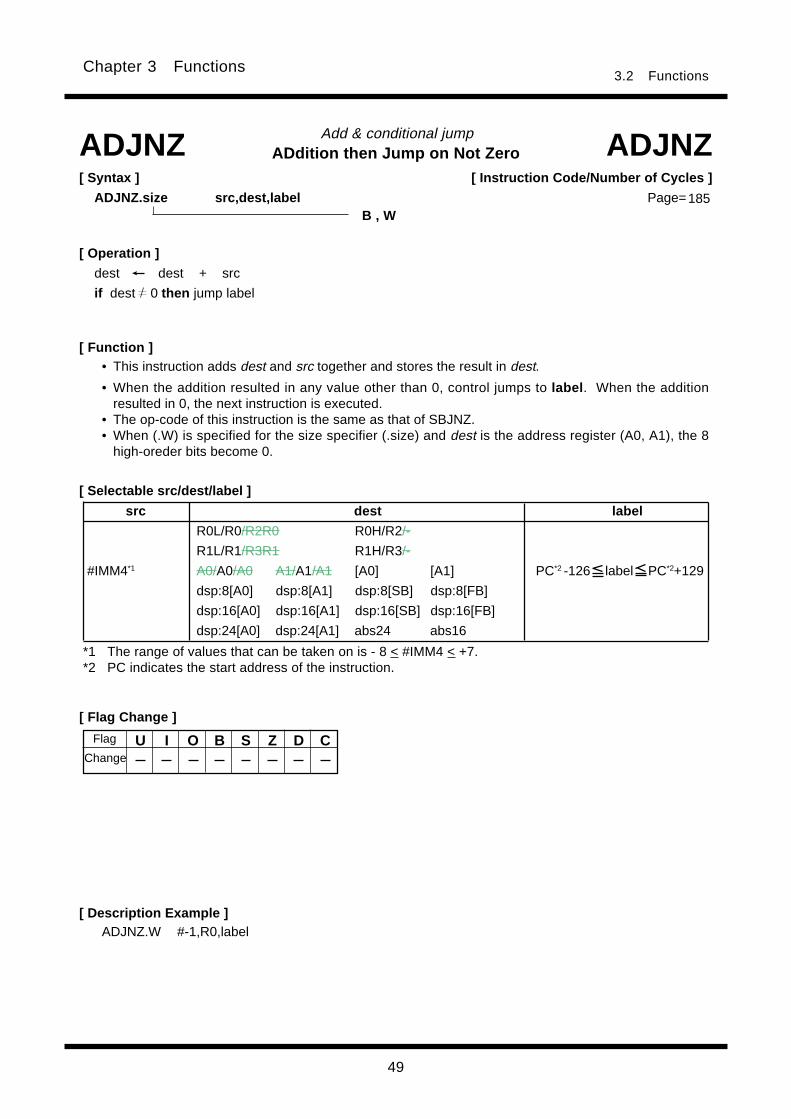
49
3.2 FunctionsChapter 3 Functions
U I O B S Z D C
Add & conditional jumpADdition then Jump on Not Zero
ADJNZ.W #-1,R0,label
[ Function ]
ADJNZ ADJNZ[ Syntax ]
ADJNZ.size src,dest,label
[ Flag Change ]
[ Description Example ]
B , W
[ Operation ]
dest dest + src
if dest 0 then jump label
[ Selectable src/dest/label ]
• This instruction adds dest and src together and stores the result in dest.
• When the addition resulted in any value other than 0, control jumps to label . When the additionresulted in 0, the next instruction is executed.
• The op-code of this instruction is the same as that of SBJNZ.• When (.W) is specified for the size specifier (.size) and dest is the address register (A0, A1), the 8
high-oreder bits become 0.
*1 The range of values that can be taken on is - 8 < #IMM4 < +7.*2 PC indicates the start address of the instruction.
185
[ Instruction Code/Number of Cycles ]
Page=
Flag
Change
src dest label
R0L/R0/R2R0 R0H/R2/-
R1L/R1/R3R1 R1H/R3/-
#IMM4*1 A0/A0/A0 A1/A1/A1 [A0] [A1] PC*2 -126 label PC*2+129
dsp:8[A0] dsp:8[A1] dsp:8[SB] dsp:8[FB]
dsp:16[A0] dsp:16[A1] dsp:16[SB] dsp:16[FB]
dsp:24[A0] dsp:24[A1] abs24 abs16
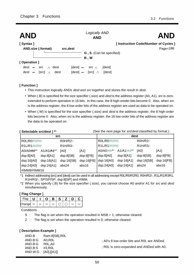
50
3.2 FunctionsChapter 3 Functions
ANDLogically AND
[ Function ]
AND AND[ Syntax ]
AND.size (:format) src,dest
[ Selectable src/dest ] * 1
[ Flag Change ]
Conditions
S : The flag is set when the operation resulted in MSB = 1; otherwise cleared.
Z : The flag is set when the operation resulted in 0; otherwise cleared.
[ Description Example ]
AND.B Ram:8[SB],R0LAND.B:G A0,R0LAND.B:G R0L,A0AND.B:S #3,R0LAND.W:G [A0],[[A1]]
G , S (Can be specified)
B , W[ Operation ]
dest src dest [dest] src [dest]
dest [src] dest [dest] [src] [dest]
• This instruction logically ANDs dest and src together and stores the result in dest.
• When (.B) is specified for the size specifier (.size) and dest is the address register (A0, A1), src is zero-
extended to perform operation in 16 bits. In this case, the 8 high-oreder bits become 0. Also, when src
is the address register, the 8 low-order bits of the address register are used as data to be operated on.
• When (.W) is specified for the size specifier (.size) and dest is the address register, the 8 high-order
bits become 0. Also, when src is the address register, the 16 low-order bits of the address register are
the data to be operated on.
; A0's 8 low-order bits and R0L are ANDed.
; R0L is zero-expanded and ANDed with A0.
U I O B S Z D C
(See the next page for src/dest classified by format.)
[ Instruction Code/Number of Cycles ]
Page=186
Change
Flag
*1 Indirect addressing [src] and [dest] can be used in all addressing except R0L/R0/R2R0, R0H/R2/-, R1L/R1/R3R1,R1H/R3/-, SP/SP/SP, dsp:8[SP] and #IMM.
*2 When you specify (.B) for the size specifier (.size), you cannot choose A0 and/or A1 for src and destsimultaneously.
src dest
R0L/R0/R2R0 R0H/R2/-
R1L/R1/R2R0 R1H/R3/-
A0/A0/A0*2 A1/A1/A1*2 [A0] [A1]
dsp:8[A0] dsp:8[A1] dsp:8[SB] dsp:8[FB]
dsp:16[A0] dsp:16[A1] dsp:16[SB] dsp:16[FB]
dsp:24[A0] dsp:24[A1] abs24 abs16
#IMM8/#IMM16
R0L/R0/R2R0 R0H/R2/-
R1L/R1/R2R0 R1H/R3/-
A0/A0/A0*2 A1/A1/A1*2 [A0] [A1]
dsp:8[A0] dsp:8[A1] dsp:8[SB] dsp:8[FB]
dsp:16[A0] dsp:16[A1] dsp:16[SB] dsp:16[FB]
dsp:24[A0] dsp:24[A1] abs24 abs16

51
3.2 FunctionsChapter 3 Functions
[src/dest Classified by Format]
G format* 1
S format *3
*3 Indirect addressing [src] and [dest] can be used in all addressing except R0L/R0/R2R0, R0H/R2/-, R1L/R1/R3R1,R1H/R3/-, SP/SP/SP, dsp:8[SP], and #IMM.
*1 Indirect addressing [src] and [dest] can be used in all addressing except R0L/R0/R2R0, R0H/R2/-, R1L/R1/R3R1,R1H/R3/-, SP/SP/SP, dsp:8[SP], and #IMM.
*2 When you specify (.B) for the size specifier (.size), you cannot choose A0 and/or A1 for src and destsimultaneously.
src dest
R0L/R0 dsp:8[SB] dsp:8[FB] abs16 R0L/R0 dsp:8[SB] dsp:8[FB] abs16
#IMM8/#IMM16
src dest
R0L/R0/R2R0 R0H/R2/-
R1L/R1/R2R0 R1H/R3/-
A0/A0/A0*2 A1/A1/A1*2 [A0] [A1]
dsp:8[A0] dsp:8[A1] dsp:8[SB] dsp:8[FB]
dsp:16[A0] dsp:16[A1] dsp:16[SB] dsp:16[FB]
dsp:24[A0] dsp:24[A1] abs24 abs16
#IMM8/#IMM16
R0L/R0/R2R0 R0H/R2/-
R1L/R1/R2R0 R1H/R3/-
A0/A0/A0*2 A1/A1/A1*2 [A0] [A1]
dsp:8[A0] dsp:8[A1] dsp:8[SB] dsp:8[FB]
dsp:16[A0] dsp:16[A1] dsp:16[SB] dsp:16[FB]
dsp:24[A0] dsp:24[A1] abs24 abs16

52
3.2 FunctionsChapter 3 Functions
• This instruction logically ANDs the C flag and src together and stores the result in the C flag.
• When src is the address register (A0, A1), you can specify the 8 low-order bits for the address register.
Bit AND carry flagLogically AND bits
[ Function ]
BAND BAND[ Syntax ]
BAND src
[ Selectable src ]
[ Flag Change ]
Conditions
C : The flag is set when the operation resulted in 1; otherwise cleared.
[ Description Example ]BAND flag
BAND 4,Ram
BAND 16,Ram:19[SB]
BAND 5,[A0]
[ Operation ]
C src C
U I O B S Z D CChange
[ Instruction Code/Number of Cycles ]
Page=188
Flag
src
bit,R0L bit,R0H bit,R1L bit,R1H
bit,A0 bit,A1 bit,[A0] bit,[A1]
bit,base:11[A0] bit,base:11[A1] bit,base:11[SB] bit,base:11[FB]
bit,base:19[A0] bit,base:19[A1] bit,base:19[SB] bit,base:19[FB]
bit,base:27[A0] bit,base:27[A1] bit,base:27 bit,base:19
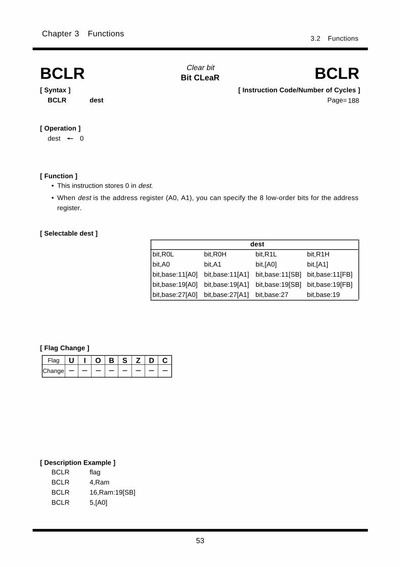
53
3.2 FunctionsChapter 3 Functions
Bit CLeaRClear bit
[ Syntax ]
BCLR dest
[ Function ]
BCLR
[ Selectable dest ]
[ Description Example ]BCLR flag
BCLR 4,Ram
BCLR 16,Ram:19[SB]
BCLR 5,[A0]
[ Operation ]
dest 0
• This instruction stores 0 in dest.
• When dest is the address register (A0, A1), you can specify the 8 low-order bits for the address
register.
U I O B S Z D C
BCLR[ Instruction Code/Number of Cycles ]
Page= 188
Flag
Change
[ Flag Change ]
dest
bit,R0L bit,R0H bit,R1L bit,R1H
bit,A0 bit,A1 bit,[A0] bit,[A1]
bit,base:11[A0] bit,base:11[A1] bit,base:11[SB] bit,base:11[FB]
bit,base:19[A0] bit,base:19[A1] bit,base:19[SB] bit,base:19[FB]
bit,base:27[A0] bit,base:27[A1] bit,base:27 bit,base:19

54
3.2 FunctionsChapter 3 Functions
• This instruction modifies addressing of the next bit instruction.
• No interrupt request is accepted immediately after this instruction.
• The operand specified in src constitutes the src or dest index value for the next bit instruction.
• For details, refer to Section 3.3, "Index Instructions."
BIT INDEXBit index
[ Function ]
BITINDEX BITINDEX[ Syntax ]
BITINDEX.size src
[ Selectable src ]
[ Flag Change ]
[ Description Example ]BITINDEX R0
BITINDEX [A0]
[ Operation ]
U I O B S Z D CChange
[ Instruction Code/Number of Cycles ]
Page=
Flag
src
R0L/R0/R2R0 R0H/R2/-
R1L/R1/R3R1 R1H/R3/-
A0/A0/A0 A1/A1/A1 [A0] [A1]
dsp:8[A0] dsp:8[A1] dsp:8[SB] dsp:8[FB]
dsp:16[A0] dsp:16[A1] dsp:16[SB] dsp:16[FB]
dsp:24[A0] dsp:24[A1] abs:24 abs:16
B , W189

55
3.2 FunctionsChapter 3 Functions
Cnd Condition Expression Cnd Condition Expression
GEU/C C=1 Equal to or greater than LTU/NC C=0 Smaller than
C flag is 1. C flag is 0.
EQ/Z Z=1 Equal to = NE/NZ Z=0 Not equal ≠Z flag is 1. Z flag is 0.
GTU____
C Z=1 Greater than LEU____
C Z=0 Equal to or smaller than
PZ S=0 Positive or zero 0 N S=1 Negative 0
GE S O=0 Equal to or greater than LE (S O) Z=1 Equal to or smaller than
(signed value) (signed value)
GT (S O) Z=0 Greater than (signed value) LT S O=1 Smaller than (signed value)
O O=1 O flag is 1. NO O=0 O flag is 0.
Bit Move ConditionConditional bit transferBMCnd BMCnd
[ Syntax ]
BMCnd dest
[ Operation ]
if true then dest 1
else dest 0
[ Flag Change ]
[ Selectable dest ]
[ Description Example ]BMN 3,Ram:11[SB]
BMZ C
• This instruction transfers the true or false value of the condition indicated by Cnd to dest. When thecondition is true, 1 is transferred; when false, 0 is transferred.
• When dest is the address register (A0, A1), you can specify the 8 low-order bits for the addressregister.
• There are following kinds of Cnd.
*1 The flag changes when you specified the C flag for dest.
U I O B S Z D C*1
[ Function ]
[ Instruction Code/Number of Cycles ]
Page=190
Change
Flag
A
A A
A
dest
bit,R0L bit,R0H bit,R1L bit,R1H
bit,A0 bit,A1 bit,[A0] bit,[A1]
bit,base:11[A0] bit,base:11[A1] bit,base:11[SB] bit,base:11[FB]
bit,base:19[A0] bit,base:19[A1] bit,base:19[SB] bit,base:19[FB]
bit,base:27[A0] bit,base:27[A1] bit,base:27 bit,base:19
C
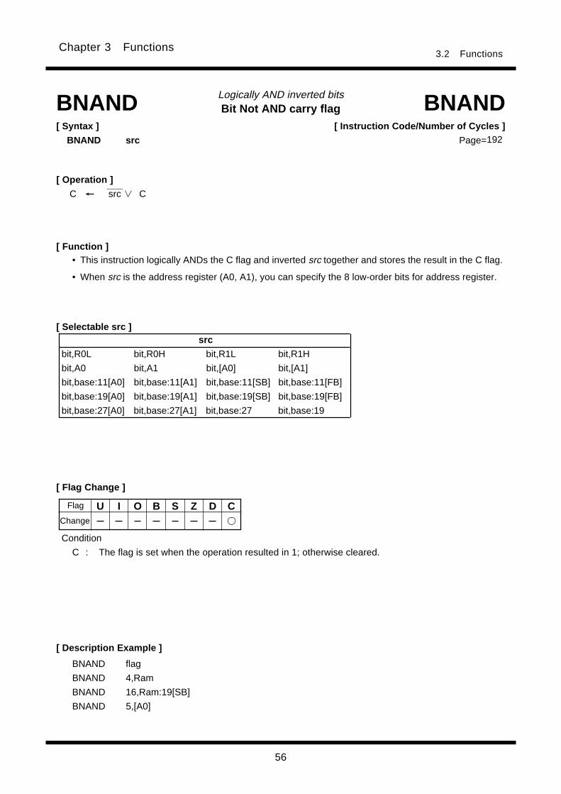
56
3.2 FunctionsChapter 3 Functions
Bit Not AND carry flagLogically AND inverted bits
[ Function ]
BNAND[ Syntax ]
BNAND src
• This instruction logically ANDs the C flag and inverted src together and stores the result in the C flag.
• When src is the address register (A0, A1), you can specify the 8 low-order bits for address register.
[ Selectable src ]
[ Flag Change ]
[ Description Example ]
BNAND flag
BNAND 4,Ram
BNAND 16,Ram:19[SB]
BNAND 5,[A0]
[ Operation ]______
C src C
Condition
C : The flag is set when the operation resulted in 1; otherwise cleared.
U I O B S Z D C
BNAND[ Instruction Code/Number of Cycles ]
Page=192
Change
Flag
src
bit,R0L bit,R0H bit,R1L bit,R1H
bit,A0 bit,A1 bit,[A0] bit,[A1]
bit,base:11[A0] bit,base:11[A1] bit,base:11[SB] bit,base:11[FB]
bit,base:19[A0] bit,base:19[A1] bit,base:19[SB] bit,base:19[FB]
bit,base:27[A0] bit,base:27[A1] bit,base:27 bit,base:19
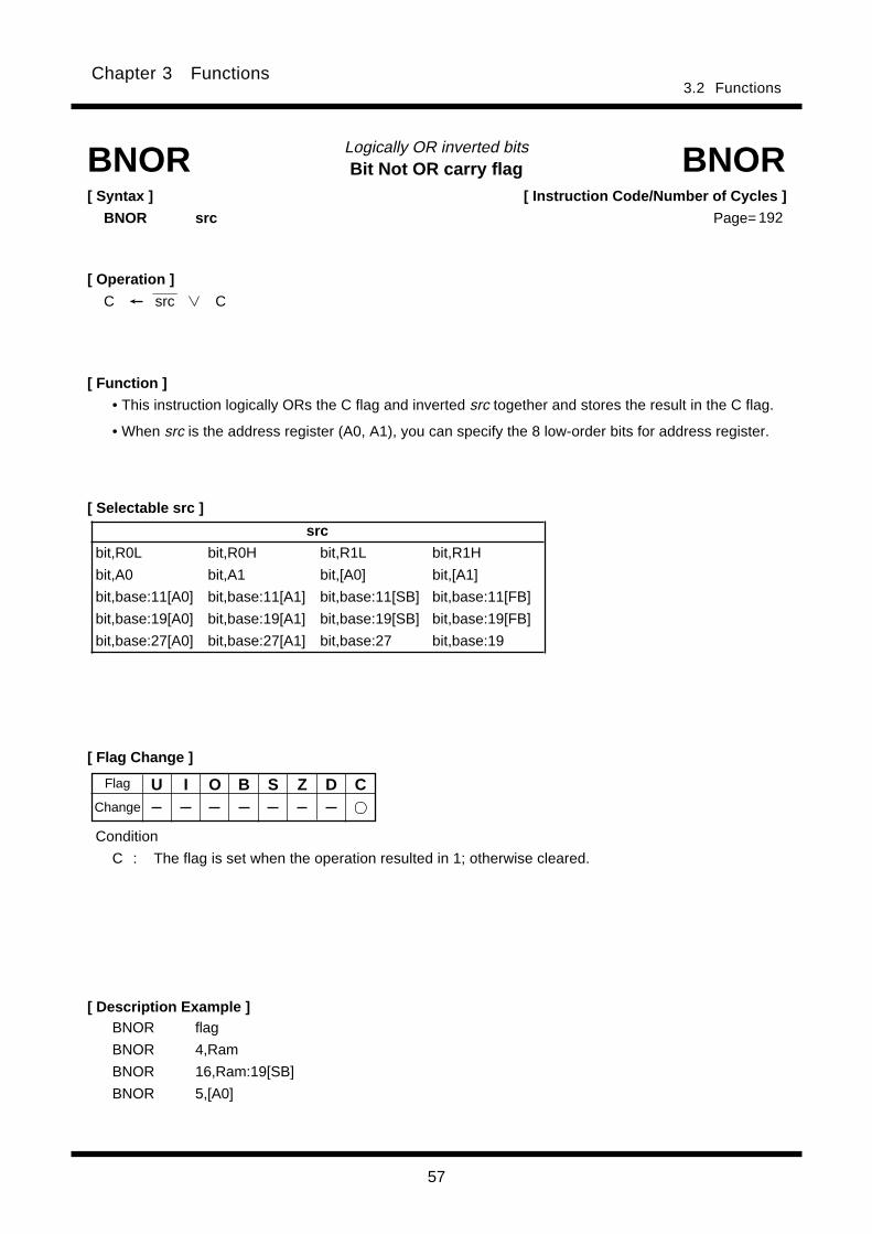
57
Chapter 3 Functions3.2 Functions
[ Instruction Code/Number of Cycles ]
Page=
Bit Not OR carry flagLogically OR inverted bits
[ Syntax ]
BNOR src
[ Description Example ]
[ Function ]
• This instruction logically ORs the C flag and inverted src together and stores the result in the C flag.
• When src is the address register (A0, A1), you can specify the 8 low-order bits for address register.
[ Selectable src ]
BNOR BNOR
[ Flag Change ]
BNOR flag
BNOR 4,Ram
BNOR 16,Ram:19[SB]
BNOR 5,[A0]
[ Operation ]______
C src C
U I O B S Z D C
Condition
C : The flag is set when the operation resulted in 1; otherwise cleared.
Flag
Change
src
bit,R0L bit,R0H bit,R1L bit,R1H
bit,A0 bit,A1 bit,[A0] bit,[A1]
bit,base:11[A0] bit,base:11[A1] bit,base:11[SB] bit,base:11[FB]
bit,base:19[A0] bit,base:19[A1] bit,base:19[SB] bit,base:19[FB]
bit,base:27[A0] bit,base:27[A1] bit,base:27 bit,base:19
192

58
Chapter 3 Functions3.2 Functions
U I O B S Z D C
Bit NOTInvert bit
[ Syntax ]
BNOT dest
[ Flag Change ]
[ Description Example ]BNOT flag
BNOT 4,Ram
BNOT 16,Ram:19[SB]
BNOT 5,[A0]
[ Function ]
BNOTBNOT
[ Selectable dest ]
Change
[ Operation ]________
dest dest
[ Instruction Code/Number of Cycles ]
Page=193
• This instruction inverts dest and stores the result in dest.
• When dest is the address register (A0, A1), you can specify the 8 low-order bits for the address regis-
ter.
Flag
dest
bit,R0L bit,R0H bit,R1L bit,R1H
bit,A0 bit,A1 bit,[A0] bit,[A1]
bit,base:11[A0] bit,base:11[A1] bit,base:11[SB] bit,base:11[FB]
bit,base:19[A0] bit,base:19[A1] bit,base:19[SB] bit,base:19[FB]
bit,base:27[A0] bit,base:27[A1] bit,base:27 bit,base:19
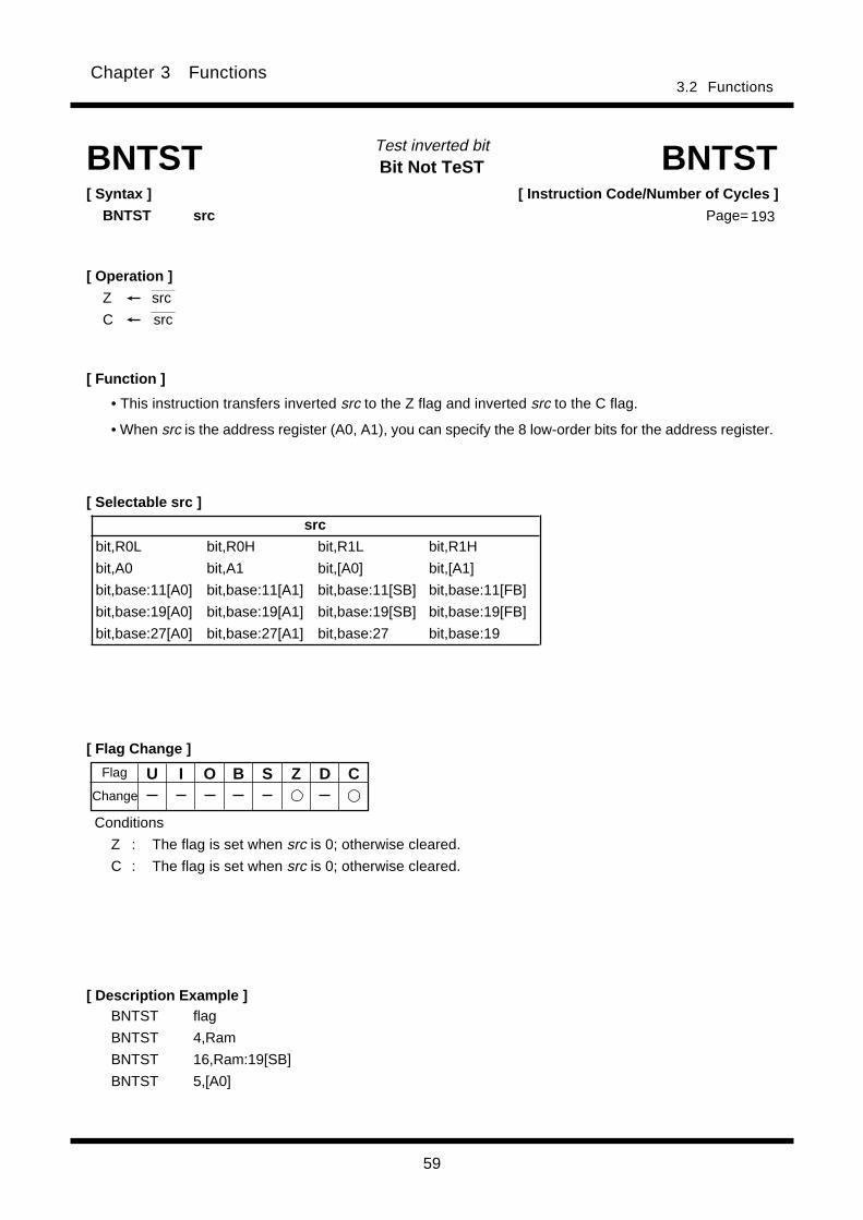
59
Chapter 3 Functions3.2 Functions
Bit Not TeSTTest inverted bit
[ Flag Change ]
[ Description Example ]
[ Function ]
[ Selectable src ]
BNTST BNTST[ Syntax ]
BNTST src
Conditions
Z : The flag is set when src is 0; otherwise cleared.
C : The flag is set when src is 0; otherwise cleared.
BNTST flag
BNTST 4,Ram
BNTST 16,Ram:19[SB]
BNTST 5,[A0]
[ Operation ]
Z src______
C src
U I O B S Z D C
[ Instruction Code/Number of Cycles ]
Page= 193
• This instruction transfers inverted src to the Z flag and inverted src to the C flag.
• When src is the address register (A0, A1), you can specify the 8 low-order bits for the address register.
Flag
Change
src
bit,R0L bit,R0H bit,R1L bit,R1H
bit,A0 bit,A1 bit,[A0] bit,[A1]
bit,base:11[A0] bit,base:11[A1] bit,base:11[SB] bit,base:11[FB]
bit,base:19[A0] bit,base:19[A1] bit,base:19[SB] bit,base:19[FB]
bit,base:27[A0] bit,base:27[A1] bit,base:27 bit,base:19
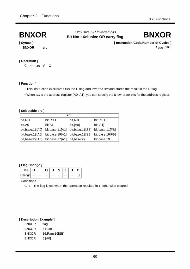
60
Chapter 3 Functions3.2 Functions
Bit Not eXclusive OR carry flagExclusive OR inverted bits
[ Flag Change ]
[ Description Example ]
[ Function ]
[ Selectable src ]
BNXOR[ Syntax ]
BNXOR src
BNXOR flag
BNXOR 4,Ram
BNXOR 16,Ram:19[SB]
BNXOR 5,[A0]
[ Operation ]______
C src C
• This instruction exclusive ORs the C flag and inverted src and stores the result in the C flag.
• When src is the address register (A0, A1), you can specify the 8 low-order bits for the address register.
U I O B S Z D C
Conditions
C : The flag is set when the operation resulted in 1; otherwise cleared.
BNXOR[ Instruction Code/Number of Cycles ]
Page= 194
Flag
Change
A
src
bit,R0L bit,R0H bit,R1L bit,R1H
bit,A0 bit,A1 bit,[A0] bit,[A1]
bit,base:11[A0] bit,base:11[A1] bit,base:11[SB] bit,base:11[FB]
bit,base:19[A0] bit,base:19[A1] bit,base:19[SB] bit,base:19[FB]
bit,base:27[A0] bit,base:27[A1] bit,base:27 bit,base:19
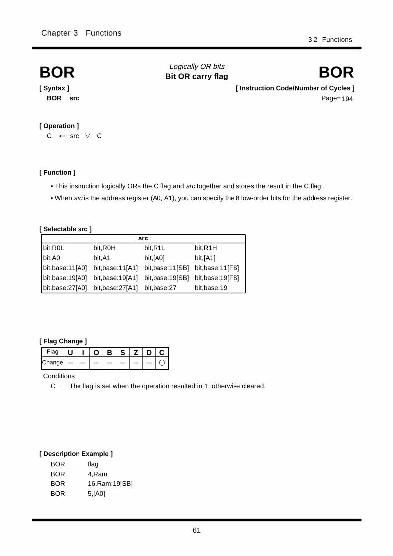
61
Chapter 3 Functions3.2 Functions
Bit OR carry flagLogically OR bits
[ Syntax ]
BOR src
[ Description Example ]
[ Function ]
[ Selectable src ]
BOR BOR
[ Flag Change ]
BOR flag
BOR 4,Ram
BOR 16,Ram:19[SB]
BOR 5,[A0]
[ Operation ]
C src C
U I O B S Z D C
Conditions
C : The flag is set when the operation resulted in 1; otherwise cleared.
• This instruction logically ORs the C flag and src together and stores the result in the C flag.
• When src is the address register (A0, A1), you can specify the 8 low-order bits for the address register.
[ Instruction Code/Number of Cycles ]
Page= 194
Flag
Change
src
bit,R0L bit,R0H bit,R1L bit,R1H
bit,A0 bit,A1 bit,[A0] bit,[A1]
bit,base:11[A0] bit,base:11[A1] bit,base:11[SB] bit,base:11[FB]
bit,base:19[A0] bit,base:19[A1] bit,base:19[SB] bit,base:19[FB]
bit,base:27[A0] bit,base:27[A1] bit,base:27 bit,base:19

62
Chapter 3 Functions3.2 Functions
BReaKDebug interrupt
BRK[ Description Example ]
[ Function ]
BRK BRK
[ Flag Change ] *1
*1 The flags are saved to the stack area before the BRK in-
struction is executed. After the interrupt, the flags
change state as shown on the left.Conditions
U : The flag is cleared.
I : The flag is cleared.
D : The flag is cleared.
[ Syntax ]
BRK
U I O B S Z D C
[ Instruction Code/Number of Cycles ]
Page= 195
• This instruction generates a BRK interrupt.
• The BRK interrupt is a nonmaskable interrupt.
Flag
Change
[ Operation ]
• When anything other than FF16 exists in ad-
dresses from FFFFE416 to FFFFE716
SP SP - 2
M(SP) FLG
SP SP - 2
M(SP)*1 (PC + 1)H
SP SP - 2
M(SP) (PC + 1)ML
PC M(FFFFE416)
*1 The 8 high-order bits become indeterminate.
• When FF16 exists in all addresses from
FFFFE416 to FFFFE716
SP SP - 2
M(SP) FLG
SP SP - 2
M(SP)*2 (PC + 1)H
SP SP - 2
M(SP) (PC + 1)ML
PC M(IntBase)
*2 The 8 high-order bits become indeterminate.
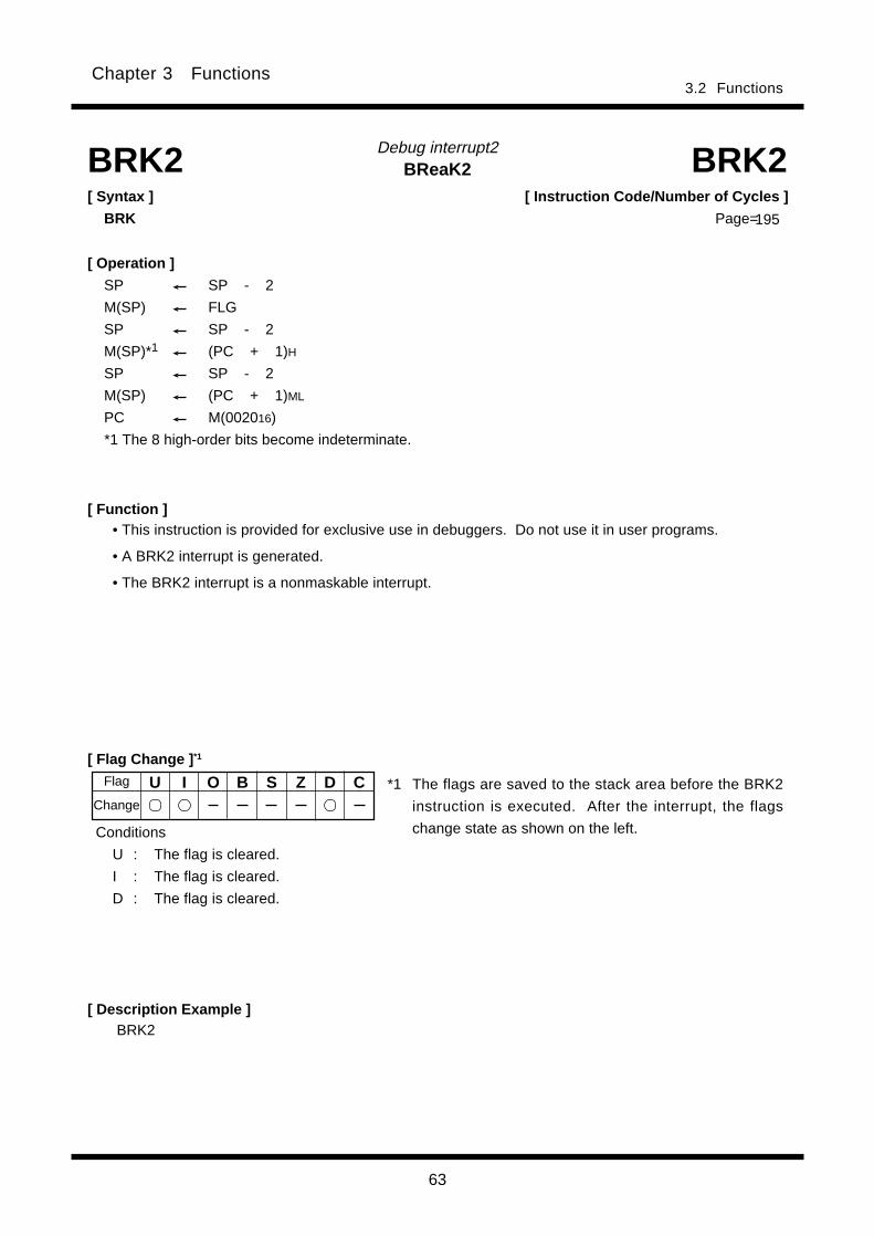
63
Chapter 3 Functions3.2 Functions
BReaK2Debug interrupt2
BRK2[ Description Example ]
[ Function ]
BRK2 BRK2
[ Flag Change ] *1
*1 The flags are saved to the stack area before the BRK2
instruction is executed. After the interrupt, the flags
change state as shown on the left.Conditions
U : The flag is cleared.
I : The flag is cleared.
D : The flag is cleared.
[ Syntax ]
BRK
U I O B S Z D C
[ Instruction Code/Number of Cycles ]
Page=
• This instruction is provided for exclusive use in debuggers. Do not use it in user programs.
• A BRK2 interrupt is generated.
• The BRK2 interrupt is a nonmaskable interrupt.
Flag
Change
[ Operation ]
SP SP - 2
M(SP) FLG
SP SP - 2
M(SP)*1 (PC + 1)H
SP SP - 2
M(SP) (PC + 1)ML
PC M(002016)
*1 The 8 high-order bits become indeterminate.
195

64
Chapter 3 Functions3.2 Functions
Bit SETSet bit
[ Flag Change ]
[ Function ]
[ Selectable dest ]
BSET BSET[ Syntax ]
BSET dest
[ Description Example ]BSET flag
BSET 4,Ram
BSET 16,Ram:19[SB]
BSET 5,[A0]
• This instruction stores 1 in dest.
• When dest is the address register (A0, A1), you can specify the 8 low-order bits for the address regis-
ter.
U I O B S Z D CChange
196
[ Instruction Code/Number of Cycles ]
Page=
Flag
[ Operation ]
dest 1
dest
bit,R0L bit,R0H bit,R1L bit,R1H
bit,A0 bit,A1 bit,[A0] bit,[A1]
bit,base:11[A0] bit,base:11[A1] bit,base:11[SB] bit,base:11[FB]
bit,base:19[A0] bit,base:19[A1] bit,base:19[SB] bit,base:19[FB]
bit,base:27[A0] bit,base:27[A1] bit,base:27 bit,base:19

65
Chapter 3 Functions3.2 Functions
Bit TeSTTest bit
[ Flag Change ]
[ Function ]
[ Selectable src ]
BTST BTST[ Syntax ]
BTST (:format) src
[ Description Example ]
BTST flag
BTST 4,Ram
BTST 16,Ram:19[SB]
BTST 5,[A0]
G , S (Can be specified)
[ Operation ]______
Z src
C src
U I O B S Z D C
Conditions
Z : The flag is set when src is 0; otherwise cleared.
C : The flag is set when src is 1; otherwise cleared.
• This instruction transfers inverted src to the Z flag and non-inverted src to the C flag.
• When src is the address register (A0, A1), you can specify the 8 low-order bits for the address register.
Change
[ Instruction Code/Number of Cycles ]
Page=196
Flag
src
bit,R0L bit,R0H bit,R1L bit,R1H
bit,A0 bit,A1 bit,[A0] bit,[A1]
bit,base:11[A0] bit,base:11[A1] bit,base:11[SB] bit,base:11[FB]
bit,base:19[A0] bit,base:19[A1] bit,base:19[SB] bit,base:19[FB]
bit,base:27[A0] bit,base:27[A1] bit,base:27 bit,base:19
src
bit,base:19
G format* 1
S format
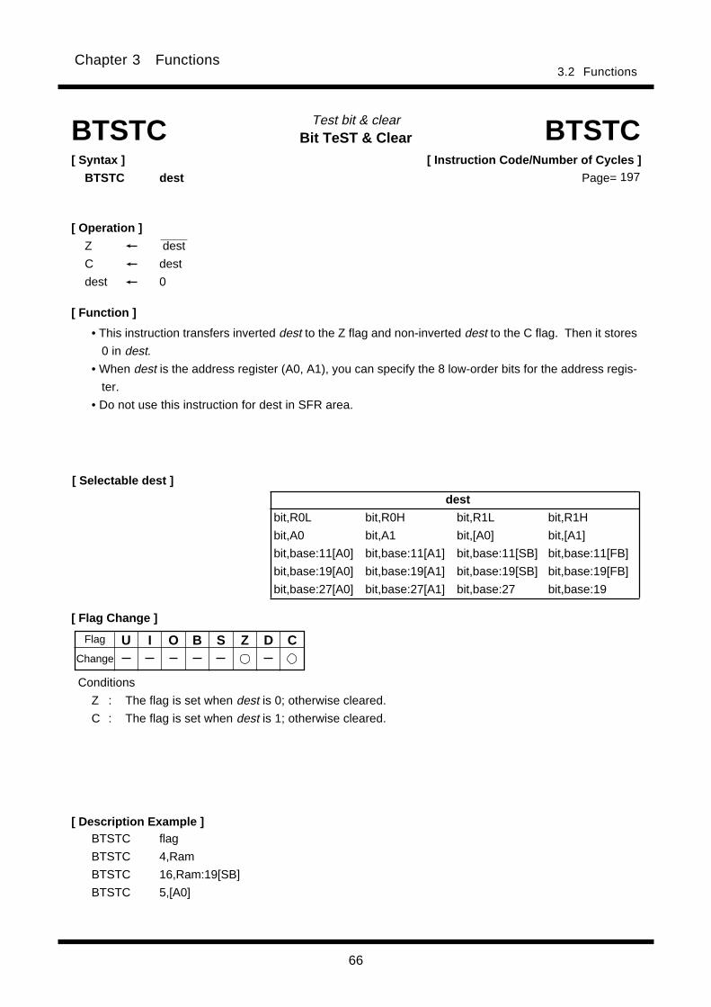
66
Chapter 3 Functions3.2 Functions
Bit TeST & ClearTest bit & clear
[ Flag Change ]
[ Description Example ]
BTSTC BTSTC[ Syntax ]
BTSTC dest
[ Selectable dest ]
BTSTC flag
BTSTC 4,Ram
BTSTC 16,Ram:19[SB]
BTSTC 5,[A0]
[ Operation ]
Z________
dest
C dest
dest 0
[ Function ]
U I O B S Z D C
Conditions
Z : The flag is set when dest is 0; otherwise cleared.
C : The flag is set when dest is 1; otherwise cleared.
• This instruction transfers inverted dest to the Z flag and non-inverted dest to the C flag. Then it stores
0 in dest.
• When dest is the address register (A0, A1), you can specify the 8 low-order bits for the address regis-
ter.
• Do not use this instruction for dest in SFR area.
[ Instruction Code/Number of Cycles ]
Page= 197
Flag
Change
dest
bit,R0L bit,R0H bit,R1L bit,R1H
bit,A0 bit,A1 bit,[A0] bit,[A1]
bit,base:11[A0] bit,base:11[A1] bit,base:11[SB] bit,base:11[FB]
bit,base:19[A0] bit,base:19[A1] bit,base:19[SB] bit,base:19[FB]
bit,base:27[A0] bit,base:27[A1] bit,base:27 bit,base:19

67
Chapter 3 Functions3.2 Functions
Bit TeST & SetTest bit & set
[ Flag Change ]
[ Description Example ]
[ Selectable dest ]
BTSTS BTSTS
[ Function ]
• This instruction transfers inverted dest to the Z flag and non-inverted dest to the C flag. Then it stores
1 in dest.
• When dest is the address register (A0, A1), you can specify the 8 low-order bits for the address regis-
ter.
• Do not use this instruction for dest in SFR area.
Conditions
Z : The flag is set when dest is 0; otherwise cleared.
C : The flag is set when dest is 1; otherwise cleared.
BTSTS flag
BTSTS 4,Ram
BTSTS 16,Ram:19[SB]
BTSTS 5,[A0]
[ Syntax ]
BTSTS dest
[ Operation ]
Z________
dest
C dest
dest 1
U I O B S Z D C
[ Instruction Code/Number of Cycles ]
Page= 198
Flag
Change
dest
bit,R0L bit,R0H bit,R1L bit,R1H
bit,A0 bit,A1 bit,[A0] bit,[A1]
bit,base:11[A0] bit,base:11[A1] bit,base:11[SB] bit,base:11[FB]
bit,base:19[A0] bit,base:19[A1] bit,base:19[SB] bit,base:19[FB]
bit,base:27[A0] bit,base:27[A1] bit,base:27 bit,base:19
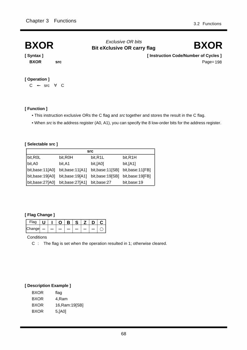
68
3.2 FunctionsChapter 3 Functions
Bit eXclusive OR carry flagExclusive OR bits
[ Flag Change ]
[ Description Example ]
[ Function ]
[ Selectable src ]
BXOR[ Syntax ]
BXOR src
BXOR
• This instruction exclusive ORs the C flag and src together and stores the result in the C flag.
• When src is the address register (A0, A1), you can specify the 8 low-order bits for the address register.
BXOR flag
BXOR 4,Ram
BXOR 16,Ram:19[SB]
BXOR 5,[A0]
[ Operation ]
C src C
U I O B S Z D C
Conditions
C : The flag is set when the operation resulted in 1; otherwise cleared.
[ Instruction Code/Number of Cycles ]
Page=
Flag
Change
A
src
bit,R0L bit,R0H bit,R1L bit,R1H
bit,A0 bit,A1 bit,[A0] bit,[A1]
bit,base:11[A0] bit,base:11[A1] bit,base:11[SB] bit,base:11[FB]
bit,base:19[A0] bit,base:19[A1] bit,base:19[SB] bit,base:19[FB]
bit,base:27[A0] bit,base:27[A1] bit,base:27 bit,base:19
198
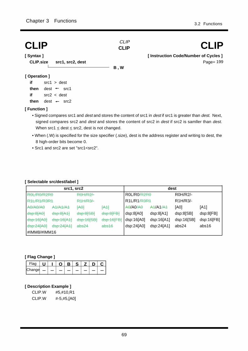
69
3.2 FunctionsChapter 3 Functions
U I O B S Z D C
CLIPCLIP
CLIP.W #5,#10,R1
CLIP.W #-5,#5,[A0]
[ Function ]
CLIP CLIP[ Syntax ]
CLIP.size src1, src2, dest
[ Flag Change ]
[ Description Example ]
B , W
[ Operation ]
if src1 > dest
then dest src1
if src2 < dest
then dest src2
[ Selectable src/dest/label ]
[ Instruction Code/Number of Cycles ]
Page=
Flag
Change
src1, src2 dest
R0L/R0/R2R0 R0H/R2/-
R1L/R1/R3R1 R1H/R3/-
A0/A0/A0 A1/A1/A1 [A0] [A1]
dsp:8[A0] dsp:8[A1] dsp:8[SB] dsp:8[FB]
dsp:16[A0] dsp:16[A1] dsp:16[SB] dsp:16[FB]
dsp:24[A0] dsp:24[A1] abs24 abs16
#IMM8/#IMM16
R0L/R0/R2R0 R0H/R2/-
R1L/R1/R3R1 R1H/R3/-
A0/A0/A0 A1/A1/A1 [A0] [A1]
dsp:8[A0] dsp:8[A1] dsp:8[SB] dsp:8[FB]
dsp:16[A0] dsp:16[A1] dsp:16[SB] dsp:16[FB]
dsp:24[A0] dsp:24[A1] abs24 abs16
• Signed compares src1 and dest and stores the content of src1 in dest if src1 is greater than dest. Next,
signed compares src2 and dest and stores the content of src2 in dest if src2 is samller than dest.
When src1 < dest < src2, dest is not changed.
• When (.W) is specified for the size specifier (.size), dest is the address register and writing to dest, the
8 high-order bits become 0.
• Src1 and src2 are set "src1<src2".
199

70
3.2 FunctionsChapter 3 Functions
[ Instruction Code/Number of Cycles ]
Page=
Compare
[ Syntax ]
CMP.size (:format) src,dest
[ Description Example ]
[ Selectable src/dest ]* 1
[ Function ]
[ Flag Change ]
CMP CMP
(See the next page for src/dest classified by format.)
CMP.B:S #10,R0LCMP.W:G R0,A0CMP.W #-3,R0CMP.B #5,Ram:8[FB]CMP.B A0,R0L
[ Operation ]
dest - src [dest] - src
dest - [src] [dest] - [src]
CoMPare
• Each flag bit of the flag register varies depending on the result of subtraction of src from dest.
• When (.B) is specified for the size specifier (.size) and dest is the address register (A0, A1), src is zero-extended to perform operation in 16 bits. Also, when src is the address register, the 8 low-order bits ofthe address register are used as data to be operated on.
• When (.L) is specified for the size specifier (.size), and src or dest is the address register, addressregister is zero-extended to perform operation in 32 bits. The flags also change states depending onthe result of 32-bit operation.
U I O B S Z D C
Conditions
O : The flag is set when a signed operation resulted in exceeding +2147483647(.L) or-2147483648(.L), +32767 (.W) or -32768 (.W), or +127 (.B) or -128 (.B); otherwise cleared.
S : The flag is set when the operation resulted in MSB = 1; otherwise cleared.Z : The flag is set when the operation resulted in 0; otherwise cleared.C : The flag is set when an unsigned operation resulted in any value equal to or greater than 0;
otherwise cleared.
; A0's 8 low-order bits and R0L are compared.
G , Q , S (Can be specified)
B , W, L
200
Flag
Change
src dest
R0L/R0/R2R0 R0H/R2/-
R1L/R1/R3R1 R1H/R3/-
A0/A0/A0*2 A1/A1/A1*2 [A0] [A1]
dsp:8[A0] dsp:8[A1] dsp:8[SB] dsp:8[FB]
dsp:16[A0] dsp:16[A1] dsp:16[SB] dsp:16[FB]
dsp:24[A0] dsp:24[A1] abs24 abs16
#IMM4/#IMM8/#IMM16/#IMM32
R0L/R0/R2R0 R0H/R2/-
R1L/R1/R3R1 R1H/R3/-
A0/A0/A0*2 A1/A1/A1*2 [A0] [A1]
dsp:8[A0] dsp:8[A1] dsp:8[SB] dsp:8[FB]
dsp:16[A0] dsp:16[A1] dsp:16[SB] dsp:16[FB]
dsp:24[A0] dsp:24[A1] abs24 abs16
*1 Indirect addressing [src] and [dest] can be used in all addressing except R0L/R0/R2R0, R0H/R2/-, R1L/R1/R3R1,R1H/R3/-, SP/SP/SP, dsp:8[SP], and #IMM.
*2 If you specify (.B) for the size specifier (.size), you cannot choose A0 and/or A1 for src and dest simul-taneously.

71
3.2 FunctionsChapter 3 Functions
[src/dest Classified by Format]
S format *6*7
Q format* 3*4
G format* 1
*1 Indirect addressing [src] and [dest] can be used in all addressing except R0L/R0/R2R0, R0H/R2/-, R1L/R1/R3R1,R1H/R3/-, SP/SP/SP, dsp:8[SP], and #IMM.
*2 If you specify (.B) for the size specifier (.size), you cannot choose A0 and/or A1 for src and dest simul-taneously.
src dest
R0L/R0 dsp:8[SB] dsp:8[FB] abs16 R0L/R0 dsp:8[SB] dsp:8[FB] abs16
#IMM8/#IMM16
R0L/R0 dsp:8[SB] dsp:8[FB] abs16 R0L/R0 dsp:8[SB] dsp:8[FB] abs16
#IMM
src dest
R0L/R0/R2R0 R0H/R2/-
R1L/R1/R3R1 R1H/R3/-
A0/A0/A0*2 A1/A1/A1*2 [A0] [A1]
dsp:8[A0] dsp:8[A1] dsp:8[SB] dsp:8[FB]
dsp:16[A0] dsp:16[A1] dsp:16[SB] dsp:16[FB]
dsp:24[A0] dsp:24[A1] abs24 abs16
#IMM4/#IMM8/#IMM16/#IMM32
R0L/R0/R2R0 R0H/R2/-
R1L/R1/R3R1 R1H/R3/-
A0/A0/A0*2 A1/A1/A1*2 [A0] [A1]
dsp:8[A0] dsp:8[A1] dsp:8[SB] dsp:8[FB]
dsp:16[A0] dsp:16[A1] dsp:16[SB] dsp:16[FB]
dsp:24[A0] dsp:24[A1] abs24 abs16
src dest
R0L/R0/R2R0 R0H/R2/-
R1L/R1/R3R1 R1H/R3/-
A0/A0/A0 A1/A1/A1 [A0] [A1]
dsp:8[A0] dsp:8[A1] dsp:8[SB] dsp:8[FB]
dsp:16[A0] dsp:16[A1] dsp:16[SB] dsp:16[FB]
dsp:24[A0] dsp:24[A1] abs24 abs16
#IMM4*5/#IMM8/#IMM16/#IMM32
R0L/R0/R2R0 R0H/R2/-
R1L/R1/R3R1 R1H/R3/-
A0/A0/A0 A1/A1/A1 [A0] [A1]
dsp:8[A0] dsp:8[A1] dsp:8[SB] dsp:8[FB]
dsp:16[A0] dsp:16[A1] dsp:16[SB] dsp:16[FB]
dsp:24[A0] dsp:24[A1] abs24 abs16
*3 Indirect addressing [src] and [dest] can be used in all addressing except R0L/R0/R2R0, R0H/R2/-, R1L/R1/R3R1,R1H/R3/-, SP/SP/SP, dsp:8[SP], and #IMM.
*4 You can only specify (.B) or (.W) for the size specifier (.size).*5 The range of values that can be taken on is -8 < #IMM4 < +7.
*6 Indirect addressing [src] and [dest] can be used in all addressing except R0L/R0/R2R0, R0H/R2/-, R1L/R1/R3R1,R1H/R3/-, SP/SP/SP, dsp:8[SP], and #IMM.
*7 You can only specify (.B) or (.W) for the size specifier (.size).
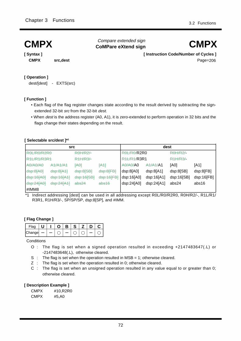
72
3.2 FunctionsChapter 3 Functions
[ Instruction Code/Number of Cycles ]
Page=
Compare extended sign
[ Syntax ]
CMPX src,dest
[ Description Example ]
[ Function ]
[ Flag Change ]
CMPX CMPX
CMPX #10,R2R0CMPX #5,A0
[ Operation ]
dest/[dest] - EXTS(src)
CoMPare eXtend sign
• Each flag of the flag register changes state according to the result derived by subtracting the sign-
extended 32-bit src from the 32-bit dest.
• When dest is the address register (A0, A1), it is zero-extended to perform operation in 32 bits and the
flags change their states depending on the result.
U I O B S Z D C
Conditions
O : The flag is set when a signed operation resulted in exceeding +2147483647(.L) or-2147483648(.L), otherwise cleared.
S : The flag is set when the operation resulted in MSB = 1; otherwise cleared.Z : The flag is set when the operation resulted in 0; otherwise cleared.C : The flag is set when an unsigned operation resulted in any value equal to or greater than 0;
otherwise cleared.
Flag
Change
*1 Indirect addressing [dest] can be used in all addressing except R0L/R0/R2R0, R0H/R2/-, R1L/R1/R3R1, R1H/R3/-, SP/SP/SP, dsp:8[SP], and #IMM.
src dest
R0L/R0/R2R0 R0H/R2/-
R1L/R1/R3R1 R1H/R3/-
A0/A0/A0 A1/A1/A1 [A0] [A1]
dsp:8[A0] dsp:8[A1] dsp:8[SB] dsp:8[FB]
dsp:16[A0] dsp:16[A1] dsp:16[SB] dsp:16[FB]
dsp:24[A0] dsp:24[A1] abs24 abs16
#IMM8
R0L/R0/R2R0 R0H/R2/-
R1L/R1/R3R1 R1H/R3/-
A0/A0/A0 A1/A1/A1 [A0] [A1]
dsp:8[A0] dsp:8[A1] dsp:8[SB] dsp:8[FB]
dsp:16[A0] dsp:16[A1] dsp:16[SB] dsp:16[FB]
dsp:24[A0] dsp:24[A1] abs24 abs16
206
[ Selectable src/dest ]* 1
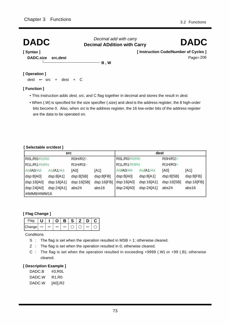
73
3.2 FunctionsChapter 3 Functions
Decimal ADdition with CarryDecimal add with carry
[ Syntax ]
DADC.size src,dest
[ Flag Change ]
[ Description Example ]
[ Function ]
[ Selectable src/dest ]
DADC DADC
DADC.B #3,R0L
DADC.W R1,R0
DADC.W [A0],R2
B , W
[ Operation ]
dest src + dest + C
U I O B S Z D C
Conditions
S : The flag is set when the operation resulted in MSB = 1; otherwise cleared.
Z : The flag is set when the operation resulted in 0; otherwise cleared.
C : The flag is set when the operation resulted in exceeding +9999 (.W) or +99 (.B); otherwise
cleared.
• This instruction adds dest, src, and C flag together in decimal and stores the result in dest.
• When (.W) is specified for the size specifier (.size) and dest is the address register, the 8 high-order
bits become 0. Also, when src is the address register, the 16 low-order bits of the address register
are the data to be operated on.
[ Instruction Code/Number of Cycles ]
Page= 206
Flag
Change
src dest
R0L/R0/R2R0 R0H/R2/-
R1L/R1/R3R1 R1H/R3/-
A0/A0/A0 A1/A1/A1 [A0] [A1]
dsp:8[A0] dsp:8[A1] dsp:8[SB] dsp:8[FB]
dsp:16[A0] dsp:16[A1] dsp:16[SB] dsp:16[FB]
dsp:24[A0] dsp:24[A1] abs24 abs16
#IMM8/#IMM16
R0L/R0/R2R0 R0H/R2/-
R1L/R1/R3R1 R1H/R3/-
A0/A0/A0 A1/A1/A1 [A0] [A1]
dsp:8[A0] dsp:8[A1] dsp:8[SB] dsp:8[FB]
dsp:16[A0] dsp:16[A1] dsp:16[SB] dsp:16[FB]
dsp:24[A0] dsp:24[A1] abs24 abs16
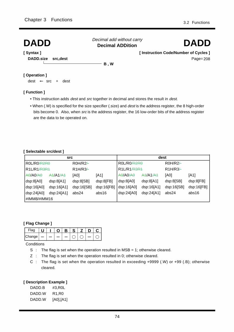
74
3.2 FunctionsChapter 3 Functions
Decimal ADDitionDecimal add without carry
[ Flag Change ]
[ Description Example ]DADD.B #3,R0L
DADD.W R1,R0
DADD.W [A0],[A1]
[ Function ]
[ Selectable src/dest ]
DADD DADD
B , W
[ Syntax ]
DADD.size src,dest
U I O B S Z D C
Conditions
S : The flag is set when the operation resulted in MSB = 1; otherwise cleared.
Z : The flag is set when the operation resulted in 0; otherwise cleared.
C : The flag is set when the operation resulted in exceeding +9999 (.W) or +99 (.B); otherwise
cleared.
• This instruction adds dest and src together in decimal and stores the result in dest.
• When (.W) is specified for the size specifier (.size) and dest is the address register, the 8 high-order
bits become 0. Also, when src is the address register, the 16 low-order bits of the address register
are the data to be operated on.
[ Instruction Code/Number of Cycles ]
Page= 208
Flag
Change
[ Operation ]
dest src + dest
src dest
R0L/R0/R2R0 R0H/R2/-
R1L/R1/R3R1 R1H/R3/-
A0/A0/A0 A1/A1/A1 [A0] [A1]
dsp:8[A0] dsp:8[A1] dsp:8[SB] dsp:8[FB]
dsp:16[A0] dsp:16[A1] dsp:16[SB] dsp:16[FB]
dsp:24[A0] dsp:24[A1] abs24 abs16
#IMM8/#IMM16
R0L/R0/R2R0 R0H/R2/-
R1L/R1/R3R1 R1H/R3/-
A0/A0/A0 A1/A1/A1 [A0] [A1]
dsp:8[A0] dsp:8[A1] dsp:8[SB] dsp:8[FB]
dsp:16[A0] dsp:16[A1] dsp:16[SB] dsp:16[FB]
dsp:24[A0] dsp:24[A1] abs24 abs16
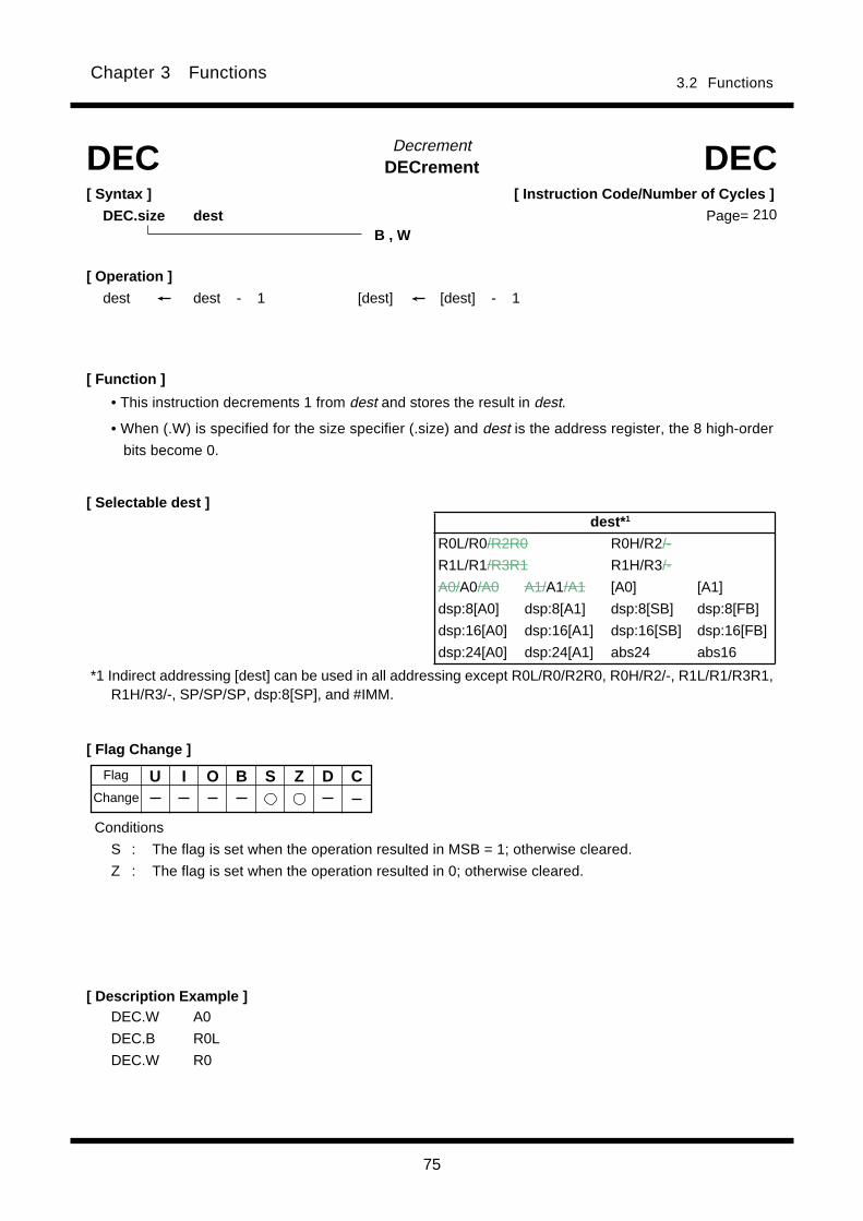
75
3.2 FunctionsChapter 3 Functions
U I O B S Z D C
DECrementDecrement
[ Syntax ]
DEC.size dest
[ Flag Change ]
[ Function ]
DEC DEC
[ Description Example ]DEC.W A0
DEC.B R0L
DEC.W R0
B , W
[ Selectable dest ]
[ Operation ]
dest dest - 1 [dest] [dest] - 1
Conditions
S : The flag is set when the operation resulted in MSB = 1; otherwise cleared.
Z : The flag is set when the operation resulted in 0; otherwise cleared.
• This instruction decrements 1 from dest and stores the result in dest.
• When (.W) is specified for the size specifier (.size) and dest is the address register, the 8 high-order
bits become 0.
[ Instruction Code/Number of Cycles ]
Page= 210
Flag
Change
dest* 1
R0L/R0/R2R0 R0H/R2/-
R1L/R1/R3R1 R1H/R3/-
A0/A0/A0 A1/A1/A1 [A0] [A1]
dsp:8[A0] dsp:8[A1] dsp:8[SB] dsp:8[FB]
dsp:16[A0] dsp:16[A1] dsp:16[SB] dsp:16[FB]
dsp:24[A0] dsp:24[A1] abs24 abs16
*1 Indirect addressing [dest] can be used in all addressing except R0L/R0/R2R0, R0H/R2/-, R1L/R1/R3R1,R1H/R3/-, SP/SP/SP, dsp:8[SP], and #IMM.
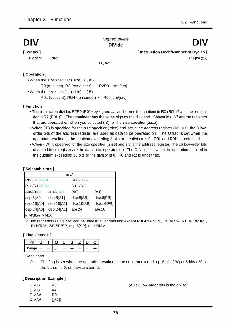
76
3.2 FunctionsChapter 3 Functions
Signed divideDIVide
DIV.B A0 ;A0's 8 low-order bits is the divisor.DIV.B #4DIV.W R0DIV.W [[A1]]
DIV DIV[ Syntax ]
DIV.size srcB , W
[ Operation ]
• When the size specifier (.size) is (.W)
R0 (quotient), R2 (remainder) R2R0 src/[src]
• When the size specifier (.size) is (.B)
R0L (quotient), R0H (remainder) R0 src/[src]
[ Flag Change ]
[ Function ]• This instruction divides R2R0 (R0)*1 by signed src and stores the quotient in R0 (R0L)*1 and the remain-
der in R2 (R0H)*1. The remainder has the same sign as the dividend. Shown in ( )*1 are the registersthat are operated on when you selected (.B) for the size specifier (.size).
• When (.B) is specified for the size specifier (.size) and src is the address register (A0, A1), the 8 low-order bits of the address register are used as data to be operated on. The O flag is set when theoperation resulted in the quotient exceeding 8 bits or the divisor is 0. R0L and R0H is undefined.
• When (.W) is specified for the size specifier (.size) and src is the address register, the 16 low-order bitsof the address register are the data to be operated on. The O flag is set when the operation resulted inthe quotient exceeding 16 bits or the divisor is 0. R0 and R2 is undefined.
[ Description Example ]
U I O B S Z D C
Conditions
O : The flag is set when the operation resulted in the quotient exceeding 16 bits (.W) or 8 bits (.B) or
the divisor is 0; otherwise cleared.
[ Instruction Code/Number of Cycles ]
Page= 210
[ Selectable src ]
Flag
Change
*2 Indirect addressing [src] can be used in all addressing except R0L/R0/R2R0, R0H/R2/-, R1L/R1/R3R1,R1H/R3/-, SP/SP/SP, dsp:8[SP], and #IMM.
src* 2
R0L/R0/R2R0 R0H/R2/-
R1L/R1/R3R1 R1H/R3/-
A0/A0/A0 A1/A1/A1 [A0] [A1]
dsp:8[A0] dsp:8[A1] dsp:8[SB] dsp:8[FB]
dsp:16[A0] dsp:16[A1] dsp:16[SB] dsp:16[FB]
dsp:24[A0] dsp:24[A1] abs24 abs16
#IMM8/#IMM16
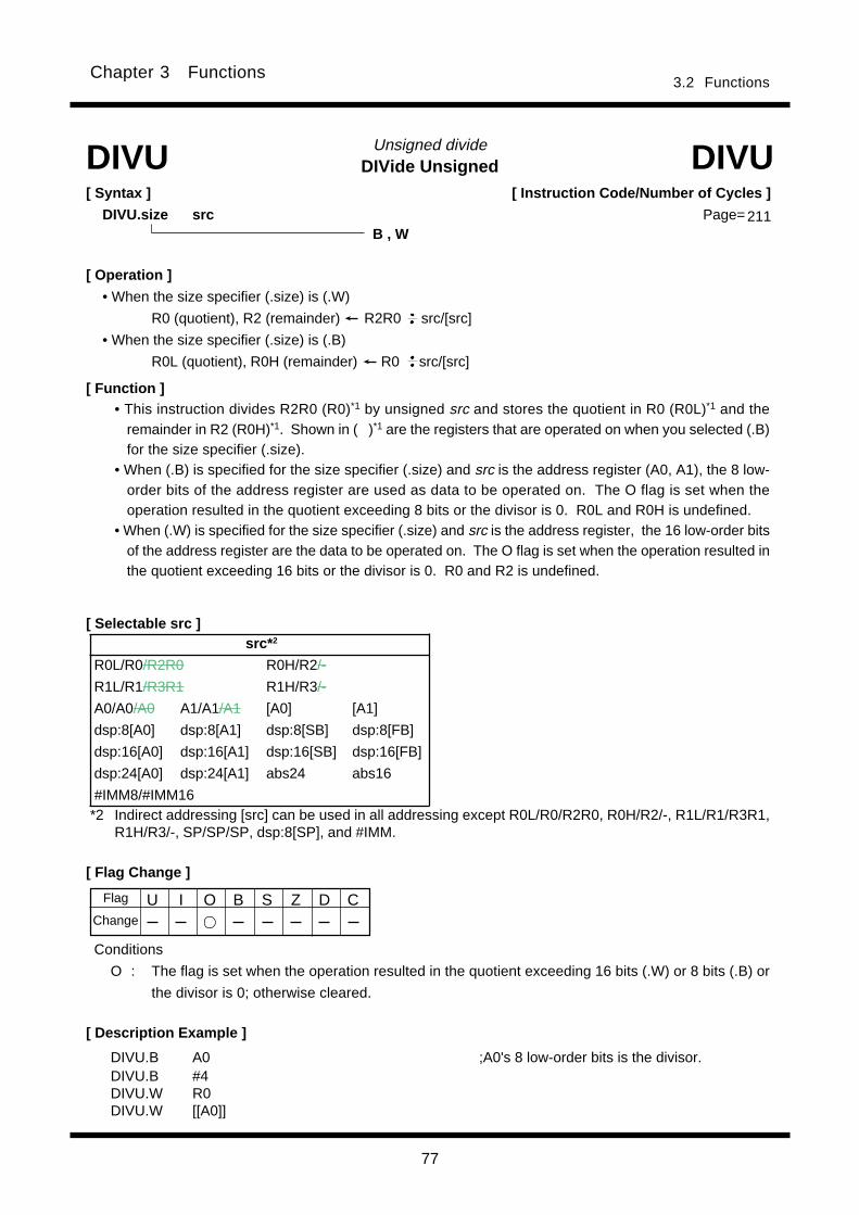
77
3.2 FunctionsChapter 3 Functions
DIVide UnsignedUnsigned divide
[ Description Example ]
DIVU DIVU[ Syntax ]
DIVU.size src
DIVU.B A0 ;A0's 8 low-order bits is the divisor.DIVU.B #4DIVU.W R0DIVU.W [[A0]]
B , W
[ Operation ]
• When the size specifier (.size) is (.W)
R0 (quotient), R2 (remainder) R2R0 src/[src]
• When the size specifier (.size) is (.B)
R0L (quotient), R0H (remainder) R0 src/[src]
[ Flag Change ]
• This instruction divides R2R0 (R0)*1 by unsigned src and stores the quotient in R0 (R0L)*1 and theremainder in R2 (R0H)*1. Shown in ( )*1 are the registers that are operated on when you selected (.B)for the size specifier (.size).
• When (.B) is specified for the size specifier (.size) and src is the address register (A0, A1), the 8 low-order bits of the address register are used as data to be operated on. The O flag is set when theoperation resulted in the quotient exceeding 8 bits or the divisor is 0. R0L and R0H is undefined.
• When (.W) is specified for the size specifier (.size) and src is the address register, the 16 low-order bitsof the address register are the data to be operated on. The O flag is set when the operation resulted inthe quotient exceeding 16 bits or the divisor is 0. R0 and R2 is undefined.
Conditions
O : The flag is set when the operation resulted in the quotient exceeding 16 bits (.W) or 8 bits (.B) or
the divisor is 0; otherwise cleared.
[ Function ]
[ Selectable src ]
[ Instruction Code/Number of Cycles ]
Page= 211
U I O B S Z D CFlag
Change
*2 Indirect addressing [src] can be used in all addressing except R0L/R0/R2R0, R0H/R2/-, R1L/R1/R3R1,R1H/R3/-, SP/SP/SP, dsp:8[SP], and #IMM.
src* 2
R0L/R0/R2R0 R0H/R2/-
R1L/R1/R3R1 R1H/R3/-
A0/A0/A0 A1/A1/A1 [A0] [A1]
dsp:8[A0] dsp:8[A1] dsp:8[SB] dsp:8[FB]
dsp:16[A0] dsp:16[A1] dsp:16[SB] dsp:16[FB]
dsp:24[A0] dsp:24[A1] abs24 abs16
#IMM8/#IMM16

78
3.2 FunctionsChapter 3 Functions
DIVide eXtensionSinged divide
[ Syntax ]
DIVX.size src
[ Description Example ]
DIVX DIVX
DIVX.B A0 ; A0's 8 low-order bits is the divisor.DIVX.B #4DIVX.W R0
B , W
[ Operation ]
• When the size specifier (.size) is (.W)
R0 (quotient), R2 (remainder) R2R0 src/[src]
• When the size specifier (.size) is (.B)
R0L (quotient), R0H (remainder) R0 src/[src]
[ Flag Change ]
U I O B S Z D CFlag
Conditions
O : The flag is set when the operation resulted in the quotient exceeding 16 bits (.W) or 8 bits (.B) or
the divisor is 0; otherwise cleared.
[ Function ]
• This instruction divides R2R0 (R0)*1 by signed src and stores the quotient in R0 (R0L)*1 and the remain-der in R2 (R0H)*1. The remainder has the same sign as the divisor. Shown in ( )*1 are the registersthat are operated on when you selected (.B) for the size specifier (.size).
• When (.B) is specified for the size specifier (.size) and src is the address register (A0, A1), the 8 low-order bits of the address register are used as data to be operated on. The O flag is set when theoperation resulted in the quotient exceeding 8 bits or the divisor is 0. R0L and R0H is undefined.
• When (.W) is specified for the size specifier (.size) and src is the address register, the 16 low-order bitsof the address register are the data to be operated on. The O flag is set when the operation resulted inthe quotient exceeding 16 bits or the divisor is 0. R0 and R2 is undefined.
[ Selectable src ]
Change
[ Instruction Code/Number of Cycles ]
Page= 212
*2 Indirect addressing [src] can be used in all addressing except R0L/R0/R2R0, R0H/R2/-, R1L/R1/R3R1,R1H/R3/-, SP/SP/SP, dsp:8[SP], and #IMM.
src* 2
R0L/R0/R2R0 R0H/R2/-
R1L/R1/R3R1 R1H/R3/-
A0/A0/A0 A1/A1/A1 [A0] [A1]
dsp:8[A0] dsp:8[A1] dsp:8[SB] dsp:8[FB]
dsp:16[A0] dsp:16[A1] dsp:16[SB] dsp:16[FB]
dsp:24[A0] dsp:24[A1] abs24 abs16
#IMM8/#IMM16
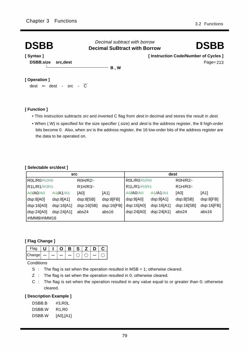
79
3.2 FunctionsChapter 3 Functions
Decimal SuBtract with BorrowDecimal subtract with borrow
[ Syntax ]
DSBB.size src,dest
[ Flag Change ]
[ Description Example ]
[ Function ]
[ Selectable src/dest ]
DSBB DSBB
• This instruction subtracts src and inverted C flag from dest in decimal and stores the result in dest.
• When (.W) is specified for the size specifier (.size) and dest is the address register, the 8 high-order
bits become 0. Also, when src is the address register, the 16 low-order bits of the address register are
the data to be operated on.
DSBB.B #3,R0L
DSBB.W R1,R0
DSBB.W [A0],[A1]
B , W
[ Operation ]____
dest dest - src - C
Conditions
S : The flag is set when the operation resulted in MSB = 1; otherwise cleared.
Z : The flag is set when the operation resulted in 0; otherwise cleared.
C : The flag is set when the operation resulted in any value equal to or greater than 0; otherwise
cleared.
U I O B S Z D C
[ Instruction Code/Number of Cycles ]
Page= 213
Flag
Change
src dest
R0L/R0/R2R0 R0H/R2/-
R1L/R1/R3R1 R1H/R3/-
A0/A0/A0 A1/A1/A1 [A0] [A1]
dsp:8[A0] dsp:8[A1] dsp:8[SB] dsp:8[FB]
dsp:16[A0] dsp:16[A1] dsp:16[SB] dsp:16[FB]
dsp:24[A0] dsp:24[A1] abs24 abs16
#IMM8/#IMM16
R0L/R0/R2R0 R0H/R2/-
R1L/R1/R3R1 R1H/R3/-
A0/A0/A0 A1/A1/A1 [A0] [A1]
dsp:8[A0] dsp:8[A1] dsp:8[SB] dsp:8[FB]
dsp:16[A0] dsp:16[A1] dsp:16[SB] dsp:16[FB]
dsp:24[A0] dsp:24[A1] abs24 abs16
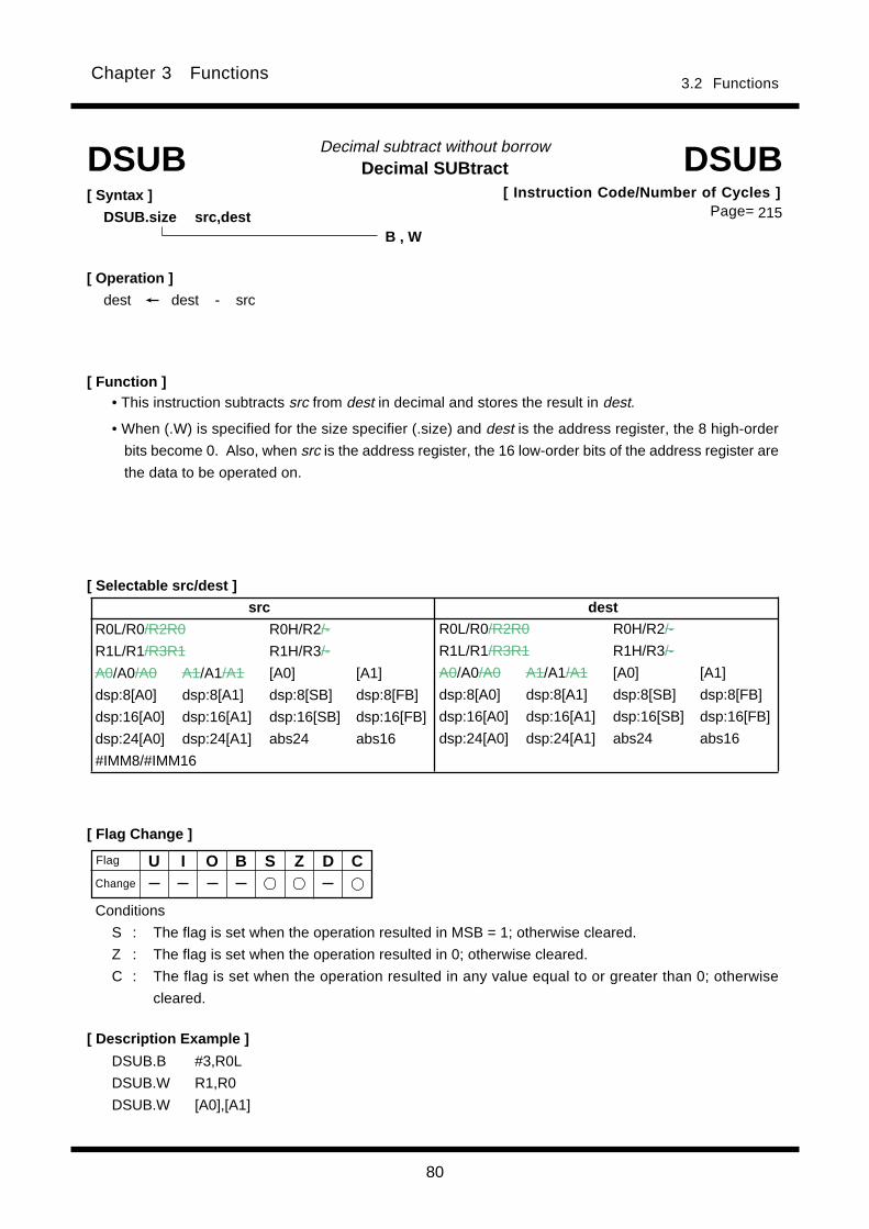
80
3.2 FunctionsChapter 3 Functions
Decimal SUBtractDecimal subtract without borrow
[ Syntax ]
DSUB.size src,dest
[ Flag Change ]
[ Description Example ]
[ Function ]
[ Selectable src/dest ]
DSUB DSUB
DSUB.B #3,R0L
DSUB.W R1,R0
DSUB.W [A0],[A1]
B , W
[ Operation ]
dest dest - src
U I O B S Z D CFlag
Conditions
S : The flag is set when the operation resulted in MSB = 1; otherwise cleared.
Z : The flag is set when the operation resulted in 0; otherwise cleared.
C : The flag is set when the operation resulted in any value equal to or greater than 0; otherwise
cleared.
• This instruction subtracts src from dest in decimal and stores the result in dest.
• When (.W) is specified for the size specifier (.size) and dest is the address register, the 8 high-order
bits become 0. Also, when src is the address register, the 16 low-order bits of the address register are
the data to be operated on.
Change
[ Instruction Code/Number of Cycles ]Page= 215
src dest
R0L/R0/R2R0 R0H/R2/-
R1L/R1/R3R1 R1H/R3/-
A0/A0/A0 A1/A1/A1 [A0] [A1]
dsp:8[A0] dsp:8[A1] dsp:8[SB] dsp:8[FB]
dsp:16[A0] dsp:16[A1] dsp:16[SB] dsp:16[FB]
dsp:24[A0] dsp:24[A1] abs24 abs16
#IMM8/#IMM16
R0L/R0/R2R0 R0H/R2/-
R1L/R1/R3R1 R1H/R3/-
A0/A0/A0 A1/A1/A1 [A0] [A1]
dsp:8[A0] dsp:8[A1] dsp:8[SB] dsp:8[FB]
dsp:16[A0] dsp:16[A1] dsp:16[SB] dsp:16[FB]
dsp:24[A0] dsp:24[A1] abs24 abs16

81
Chapter 3 Functions 3.2 Functions
ENTER functionBuild stack frame
[ Description Example ]ENTER #4
ENTER ENTER
[ Flag Change ]
[ Operation ]
SP SP - 2
M(SP)*1 FBH
SP SP - 2
M(SP) FBL
FB SP
SP SP - src *1 The 8 high-order bits become indeterminate.
[ Syntax ]
ENTER src
src
#IMM8
[ Selectable src ]
U I O B S Z D C
[ Instruction Code/Number of Cycles ]
Page=
Flag
Change
Return address (LL)
Return address (LH)
Return address (HL)
Return address (HH)
Argument of function
SP
FB
SP
After instruction execution
Auto variable area
Direction inwhich addressincreases
Number of bytesindicated by src
FB (LL)
FB(LH)
FB(HL)
FB (HH)
Return address (LL)
Return address (LH)
Return address (HL)
Return address (HH)
Argument of function
Before instruction execution
[ Function ]
• This instruction generates a stack frame. src represents the size of the stack frame. Set an even
number for src. ( You can set odd number, but it is more effective to set even number for operation.)
• The diagrams below show the stack area status before and after the ENTER instruction is executed at
the beginning of a called subroutine.
217
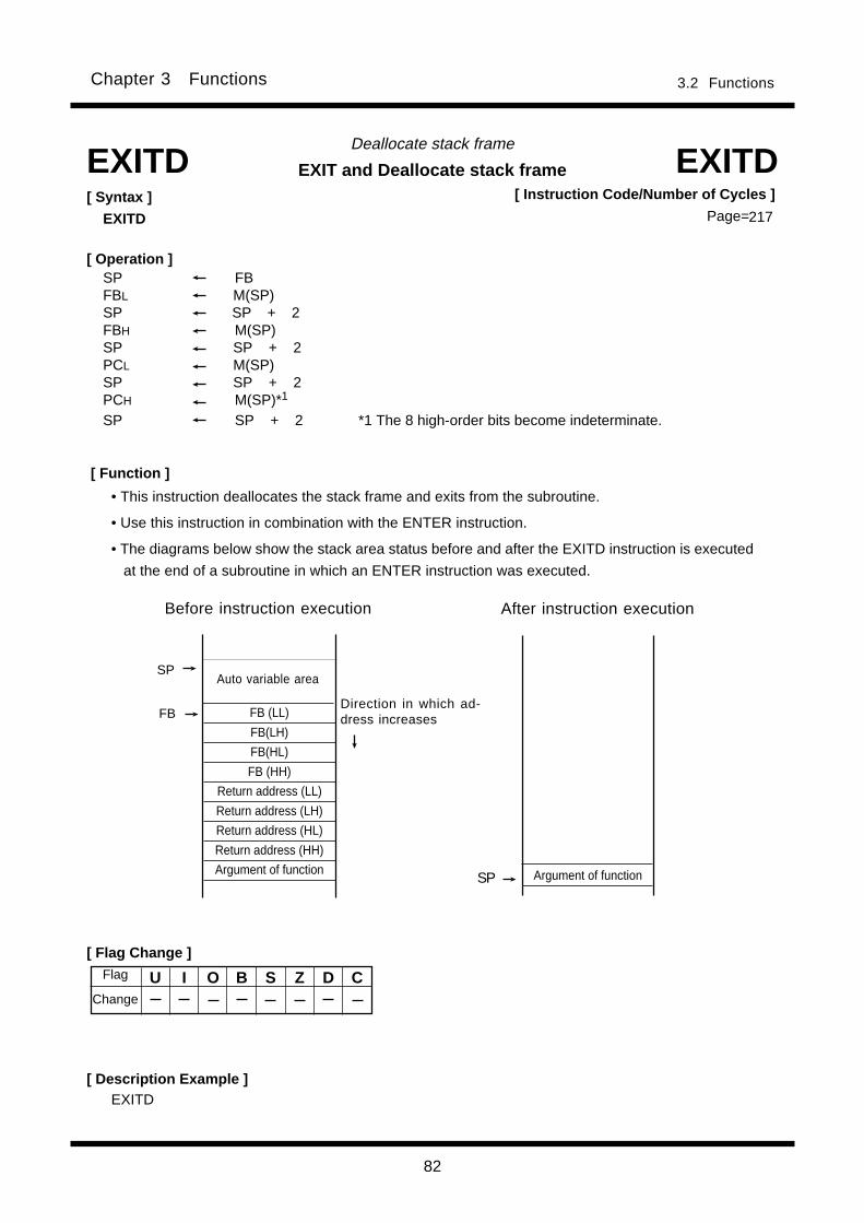
82
Chapter 3 Functions 3.2 Functions
Argument of function
[ Instruction Code/Number of Cycles ]
Page=217
EXIT and Deallocate stack frame
[ Description Example ]
[ Syntax ]
EXITD
EXITD EXITD
[ Operation ]SP FBFBL M(SP)SP SP + 2FBH M(SP)SP SP + 2PCL M(SP)SP SP + 2PCH M(SP)*1
SP SP + 2 *1 The 8 high-order bits become indeterminate.
[ Function ]
EXITD
Deallocate stack frame
• This instruction deallocates the stack frame and exits from the subroutine.
• Use this instruction in combination with the ENTER instruction.
• The diagrams below show the stack area status before and after the EXITD instruction is executed
at the end of a subroutine in which an ENTER instruction was executed.
[ Flag Change ]
U I O B S Z D CFlag
Change
SP
Direction in which ad-dress increases
Before instruction execution After instruction execution
SP
FB
Auto variable area
FB (LL)
FB(LH)
FB(HL)
FB (HH)
Return address (LL)
Return address (LH)
Return address (HL)
Return address (HH)
Argument of function
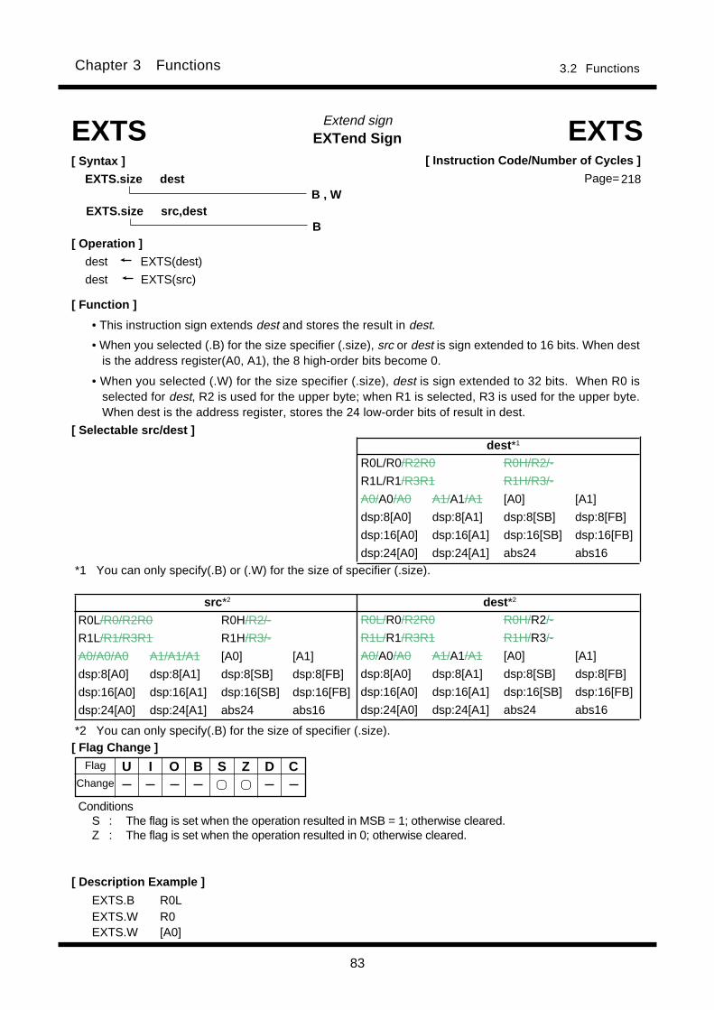
83
Chapter 3 Functions 3.2 Functions
EXTend SignExtend sign
[ Description Example ]
[ Function ]
[ Flag Change ]
EXTS EXTS[ Syntax ]
EXTS.size dest
• This instruction sign extends dest and stores the result in dest.
• When you selected (.B) for the size specifier (.size), src or dest is sign extended to 16 bits. When destis the address register(A0, A1), the 8 high-order bits become 0.
• When you selected (.W) for the size specifier (.size), dest is sign extended to 32 bits. When R0 isselected for dest, R2 is used for the upper byte; when R1 is selected, R3 is used for the upper byte.When dest is the address register, stores the 24 low-order bits of result in dest.
EXTS.B R0LEXTS.W R0EXTS.W [A0]
B , W
[ Operation ]
dest EXTS(dest)
dest EXTS(src)
U I O B S Z D C
ConditionsS : The flag is set when the operation resulted in MSB = 1; otherwise cleared.Z : The flag is set when the operation resulted in 0; otherwise cleared.
[ Selectable src/dest ]
[ Instruction Code/Number of Cycles ]
Page= 218
Flag
Change
EXTS.size src,destB
dest *1
R0L/R0/R2R0 R0H/R2/-
R1L/R1/R3R1 R1H/R3/-
A0/A0/A0 A1/A1/A1 [A0] [A1]
dsp:8[A0] dsp:8[A1] dsp:8[SB] dsp:8[FB]
dsp:16[A0] dsp:16[A1] dsp:16[SB] dsp:16[FB]
dsp:24[A0] dsp:24[A1] abs24 abs16
src *2 dest *2
R0L/R0/R2R0 R0H/R2/-
R1L/R1/R3R1 R1H/R3/-
A0/A0/A0 A1/A1/A1 [A0] [A1]
dsp:8[A0] dsp:8[A1] dsp:8[SB] dsp:8[FB]
dsp:16[A0] dsp:16[A1] dsp:16[SB] dsp:16[FB]
dsp:24[A0] dsp:24[A1] abs24 abs16
R0L/R0/R2R0 R0H/R2/-
R1L/R1/R3R1 R1H/R3/-
A0/A0/A0 A1/A1/A1 [A0] [A1]
dsp:8[A0] dsp:8[A1] dsp:8[SB] dsp:8[FB]
dsp:16[A0] dsp:16[A1] dsp:16[SB] dsp:16[FB]
dsp:24[A0] dsp:24[A1] abs24 abs16
*1 You can only specify(.B) or (.W) for the size of specifier (.size).
*2 You can only specify(.B) for the size of specifier (.size).

84
Chapter 3 Functions 3.2 Functions
EXTend ZeroExtend zero
[ Description Example ]
[ Function ]
[ Flag Change ]
EXTZ EXTZ[ Syntax ]
EXTZ src,dest
• This instruction zero-extends src to 16 bits and stores the result in dest. When dest is the addressregister(A0, A1), the 8 high-order bits become 0.
EXTZ R0L,R2EXTZ [A1],[A0]
[ Operation ]
dest EXTZ(src)
U I O B S Z D C
Conditions
S : The flag is always cleared to 0.Z : The flag is set when the operation resulted in 0; otherwise cleared.
[ Selectable src/dest ]
[ Instruction Code/Number of Cycles ]
Page=
Flag
Change
src dest
R0L/R0/R2R0 R0H/R2/-
R1L/R1/R3R1 R1H/R3/-
A0/A0/A0 A1/A1/A1 [A0] [A1]
dsp:8[A0] dsp:8[A1] dsp:8[SB] dsp:8[FB]
dsp:16[A0] dsp:16[A1] dsp:16[SB] dsp:16[FB]
dsp:24[A0] dsp:24[A1] abs24 abs16
#IMM
R0L/R0/R2R0 R0H/R2/-
R1L/R1/R3R1 R1H/R3/-
A0/A0/A0 A1/A1/A1 [A0] [A1]
dsp:8[A0] dsp:8[A1] dsp:8[SB] dsp:8[FB]
dsp:16[A0] dsp:16[A1] dsp:16[SB] dsp:16[FB]
dsp:24[A0] dsp:24[A1] abs24 abs16
220

85
Chapter 3 Functions 3.2 Functions
Flag register CLeaRClear flag register bit
[ Flag Change ]
[ Description Example ]
[ Function ]
FCLR[ Syntax ]
FCLR dest
FCLR I
FCLR S
[ Operation ]
dest 0
*1 The selected flag is cleared to 0.U I O B S Z D C*1 *1 *1 *1 *1 *1 *1 *1
• This instruction stores 0 in dest.
[ Selectable dest ]
FCLR[ Instruction Code/Number of Cycles ]
Page= 221
Flag
Change
dest
C D Z S B O I U

86
Chapter 3 Functions 3.2 Functions
Fast REturn from InTerruptFast return from Interrupt
[ Flag Change ]
[ Description Example ]
[ Function ]
FREIT[ Syntax ]
FREIT
FREIT
[ Operation ]
FLG SVF
PC SVP
*1 Becomes the content of SVF.U I O B S Z D C*1 *1 *1 *1 *1 *1 *1 *1
• Restores the contents of PC and FLG from the high-speed interrupt registers that had been saved
when accepting a high-speed interrupt request upon returning from the interrupt handler routine.
FREIT[ Instruction Code/Number of Cycles ]
Page=
Flag
Change
221

87
Chapter 3 Functions 3.2 Functions
Flag register SETSet flag register bit
[ Description Example ]
[ Function ]
[ Selectable dest ]dest
C D Z S B O I U
[ Syntax ]
FSET dest
[ Flag Change ]
FSET I
FSET S
FSET FSET
[ Operation ]
dest 1
U I O B S Z D C*1 *1 *1 *1 *1 *1 *1 *1 *1 The selected flag is set (= 1).
• This instruction stores 1 in dest.
[ Instruction Code/Number of Cycles ]
Page=222
Flag
Change
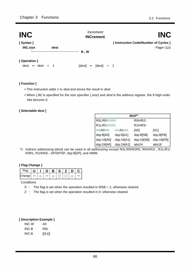
88
Chapter 3 Functions 3.2 Functions
INCrementIncrement
[ Description Example ]INC.W A0
INC.B R0L
INC.B [[A1]]
[ Function ]
[ Selectable dest ]
INC INC
[ Flag Change ]
B , W
[ Syntax ]
INC.size dest
[ Operation ]
dest dest + 1 [dest] [dest] + 1
U I O B S Z D C
Conditions
S : The flag is set when the operation resulted in MSB = 1; otherwise cleared.
Z : The flag is set when the operation resulted in 0; otherwise cleared.
• This instruction adds 1 to dest and stores the result in dest.
• When (.W) is specified for the size specifier (.size) and dest is the address register, the 8 high-order
bits become 0.
[ Instruction Code/Number of Cycles ]
Page= 223
Flag
Change
dest* 1
R0L/R0/R2R0 R0H/R2/-
R1L/R1/R3R1 R1H/R3/-
A0/A0/A0 A1/A1/A1 [A0] [A1]
dsp:8[A0] dsp:8[A1] dsp:8[SB] dsp:8[FB]
dsp:16[A0] dsp:16[A1] dsp:16[SB] dsp:16[FB]
dsp:24[A0] dsp:24[A1] abs24 abs16
*1 Indirect addressing [dest] can be used in all addressing except R0L/R0/R2R0, R0H/R2/-, R1L/R1/R3R1, R1H/R3/-, SP/SP/SP, dsp:8[SP], and #IMM.
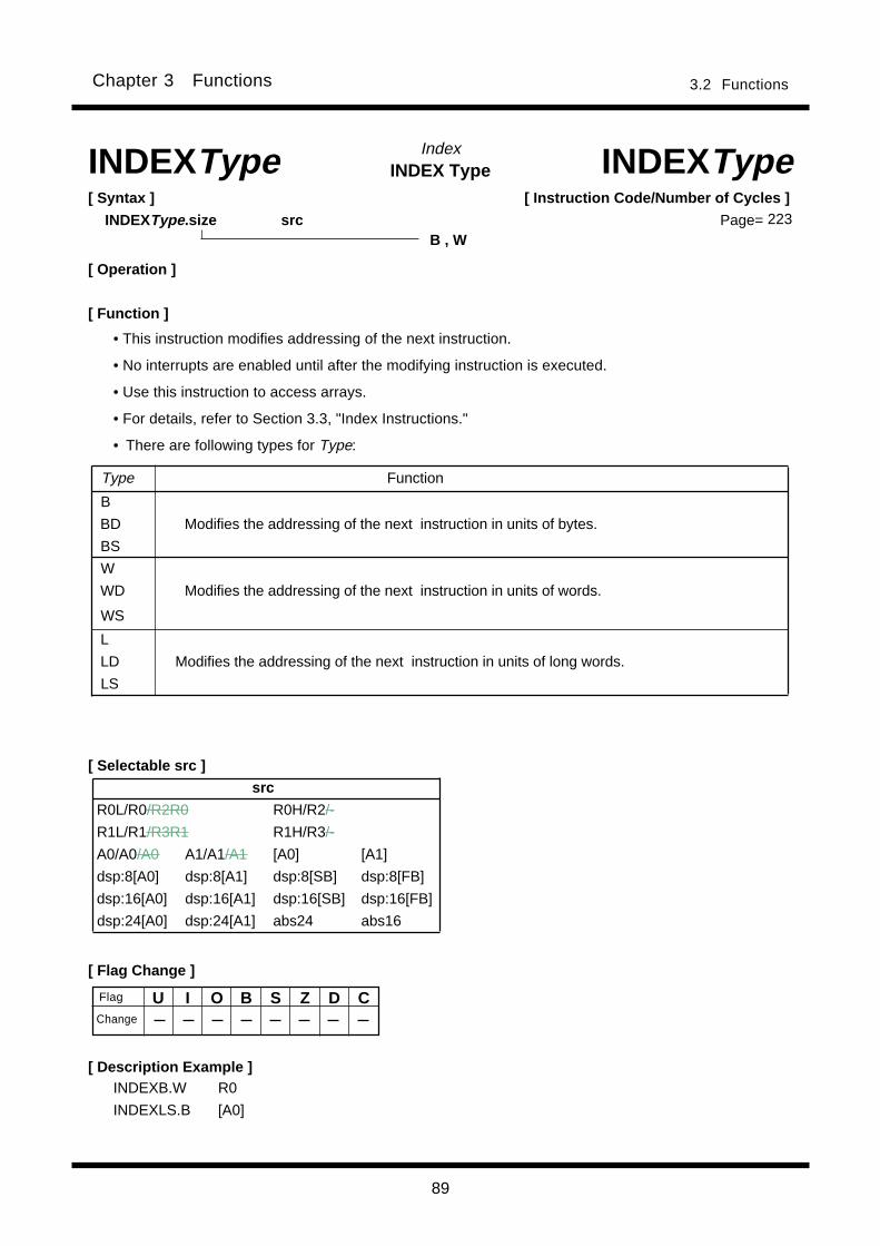
89
Chapter 3 Functions 3.2 Functions
IndexINDEX Type
[ Flag Change ]
INDEXType INDEXType[ Syntax ]
INDEXType.size src
[ Description Example ]INDEXB.W R0
INDEXLS.B [A0]
[ Operation ]
[ Selectable src ]
U I O B S Z D CFlag
Change
[ Instruction Code/Number of Cycles ]
Page=
[ Function ]
• This instruction modifies addressing of the next instruction.
• No interrupts are enabled until after the modifying instruction is executed.
• Use this instruction to access arrays.
• For details, refer to Section 3.3, "Index Instructions."
• There are following types for Type:
Type Function
B
BD Modifies the addressing of the next instruction in units of bytes.
BS
W
WD Modifies the addressing of the next instruction in units of words.
WS
L
LD Modifies the addressing of the next instruction in units of long words.
LS
src
R0L/R0/R2R0 R0H/R2/-
R1L/R1/R3R1 R1H/R3/-
A0/A0/A0 A1/A1/A1 [A0] [A1]
dsp:8[A0] dsp:8[A1] dsp:8[SB] dsp:8[FB]
dsp:16[A0] dsp:16[A1] dsp:16[SB] dsp:16[FB]
dsp:24[A0] dsp:24[A1] abs24 abs16
B , W223
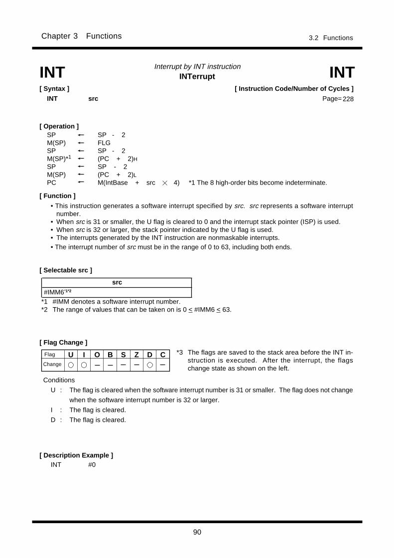
90
Chapter 3 Functions 3.2 Functions
Interrupt by INT instructionINTerrupt
[ Flag Change ]
INT INT[ Syntax ]
INT src
[ Description Example ]INT #0
[ Operation ]SP SP - 2M(SP) FLGSP SP - 2M(SP)*1 (PC + 2)HSP SP - 2M(SP) (PC + 2)LPC M(IntBase + src 4) *1 The 8 high-order bits become indeterminate.
src
#IMM6*1*2
*1 #IMM denotes a software interrupt number.*2 The range of values that can be taken on is 0 < #IMM6 < 63.
[ Selectable src ]
*3 The flags are saved to the stack area before the INT in-struction is executed. After the interrupt, the flagschange state as shown on the left.
U I O B S Z D CFlag
Conditions
U : The flag is cleared when the software interrupt number is 31 or smaller. The flag does not change
when the software interrupt number is 32 or larger.
I : The flag is cleared.
D : The flag is cleared.
Change
[ Instruction Code/Number of Cycles ]
Page= 228
[ Function ]
• This instruction generates a software interrupt specified by src. src represents a software interruptnumber.
• When src is 31 or smaller, the U flag is cleared to 0 and the interrupt stack pointer (ISP) is used.• When src is 32 or larger, the stack pointer indicated by the U flag is used.• The interrupts generated by the INT instruction are nonmaskable interrupts.• The interrupt number of src must be in the range of 0 to 63, including both ends.

91
Chapter 3 Functions 3.2 Functions
INTerrupt on OverflowInterrupt on overflow
[ Syntax ]
INTO
[ Flag Change ]
INTO INTO
[ Description Example ]
INTO
[ Operation ]SP SP - 2M(SP) FLGSP SP - 2M(SP)*1 (PC + 1)HSP SP - 2M(SP) (PC + 1)LPC M(FFFFE016) *1 The 8 high-order bits become indeterminate.
*1 The flags are saved to the stack area before the INTOinstruction is executed. After the interrupt, the flagschange state as shown on the left.
U I O B S Z D C
Conditions
U : The flag is cleared.
I : The flag is cleared.
D : The flag is cleared.
[ Instruction Code/Number of Cycles ]
Page= 228
Flag
Change
[ Function ]
• When the O flag is 1, this instruction generates an overflow interrupt. When the flag is 0, the next
instruction is executed.
• The overflow interrupt is a nonmaskable interrupt.

92
Chapter 3 Functions 3.2 Functions
Cnd Condition Expression Cnd Condition Expression
GEU/C C=1 Equal to or greater than LTU/NC C=0 Smaller than
C flag is 1. C flag is 0.
EQ/Z Z=1 Equal to = NE/NZ Z=0 Not equal
Z flag is 1. Z flag is 0.
GTU____
C Z=1 Greater than LEU____
C Z=0 Equal to or smaller than
PZ S=0 Positive or zero 0 N S=1 Negative 0
GE S O=0 Equal to or greater than LE (S O) Z=1 Equal to or smaller than
(signed value) (signed value)
GT (S O) Z=0 Greater than (signed value) LT S O=1 Smaller than (signed value)
O O=1 O flag is 1. NO O=0 O flag is 0.
≠
Jump on ConditionJump on condition
[ Syntax ]
JCnd label
[ Selectable label ]
[ Description Example ]JEQ label
JNE label
[ Function ]
[ Operation ]
if true then jump label
JCnd
[ Flag Change ]
label Cnd
PC*1-127 label PC*1+128 GEU/C, GTU, EQ/Z, N, LTU/NC, LEU, NE/NZ, PZ,
LE, O, GE, GT, NO, LT
U I O B S Z D C
*1 PC indicates the start address of the instruction.
JCnd[ Instruction Code/Number of Cycles ]
Page= 229
• This instruction causes program flow to branch off after checking the execution result of the precedinginstruction against the following condition. When the condition indicated by Cnd is true, control jumpsto label . When false, the next instruction is executed.
• The following conditions can be used for Cnd:
Flag
Change
A
A A
A
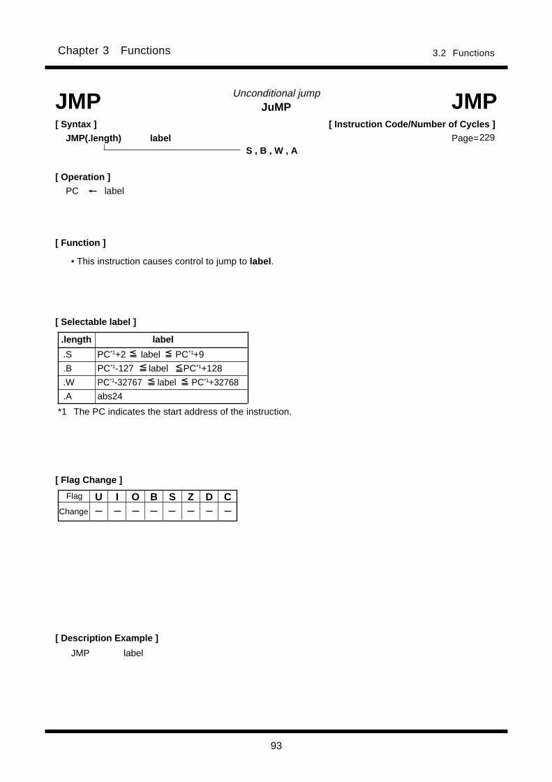
93
Chapter 3 Functions 3.2 Functions
JuMPUnconditional jump
[ Syntax ]
JMP(.length) label
[ Description Example ]
JMP JMP
[ Function ]
[ Selectable label ]
JMP label
S , B , W , A
[ Operation ]
PC label
.length label
.S PC*1+2 label PC*1+9
.B PC*1-127 label PC*1+128
.W PC*1-32767 label PC*1+32768
.A abs24
*1 The PC indicates the start address of the instruction.
• This instruction causes control to jump to label .
[ Instruction Code/Number of Cycles ]
Page=229
[ Flag Change ]
U I O B S Z D CFlag
Change
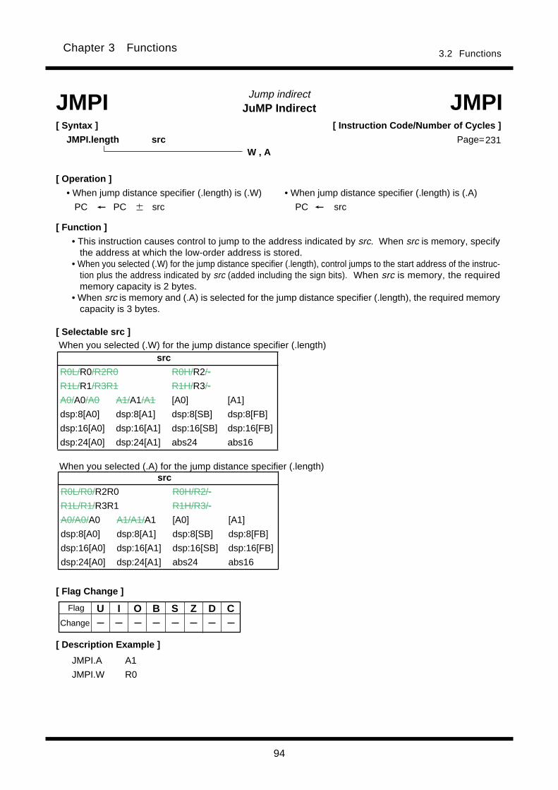
94
Chapter 3 Functions 3.2 Functions
[ Operation ]
• When jump distance specifier (.length) is (.W) • When jump distance specifier (.length) is (.A)
PC PC src PC src
JuMP IndirectJump indirect
[ Description Example ]
JMPI JMPI[ Syntax ]
JMPI.length src
[ Selectable src ]
JMPI.A A1
JMPI.W R0
W , A
[ Flag Change ]
U I O B S Z D C
[ Instruction Code/Number of Cycles ]
Page=
When you selected (.A) for the jump distance specifier (.length)
When you selected (.W) for the jump distance specifier (.length)
Flag
Change
[ Function ]
• This instruction causes control to jump to the address indicated by src. When src is memory, specifythe address at which the low-order address is stored.
• When you selected (.W) for the jump distance specifier (.length), control jumps to the start address of the instruc-tion plus the address indicated by src (added including the sign bits). When src is memory, the requiredmemory capacity is 2 bytes.
• When src is memory and (.A) is selected for the jump distance specifier (.length), the required memorycapacity is 3 bytes.
src
R0L/R0/R2R0 R0H/R2/-
R1L/R1/R3R1 R1H/R3/-
A0/A0/A0 A1/A1/A1 [A0] [A1]
dsp:8[A0] dsp:8[A1] dsp:8[SB] dsp:8[FB]
dsp:16[A0] dsp:16[A1] dsp:16[SB] dsp:16[FB]
dsp:24[A0] dsp:24[A1] abs24 abs16
src
R0L/R0/R2R0 R0H/R2/-
R1L/R1/R3R1 R1H/R3/-
A0/A0/A0 A1/A1/A1 [A0] [A1]
dsp:8[A0] dsp:8[A1] dsp:8[SB] dsp:8[FB]
dsp:16[A0] dsp:16[A1] dsp:16[SB] dsp:16[FB]
dsp:24[A0] dsp:24[A1] abs24 abs16
231
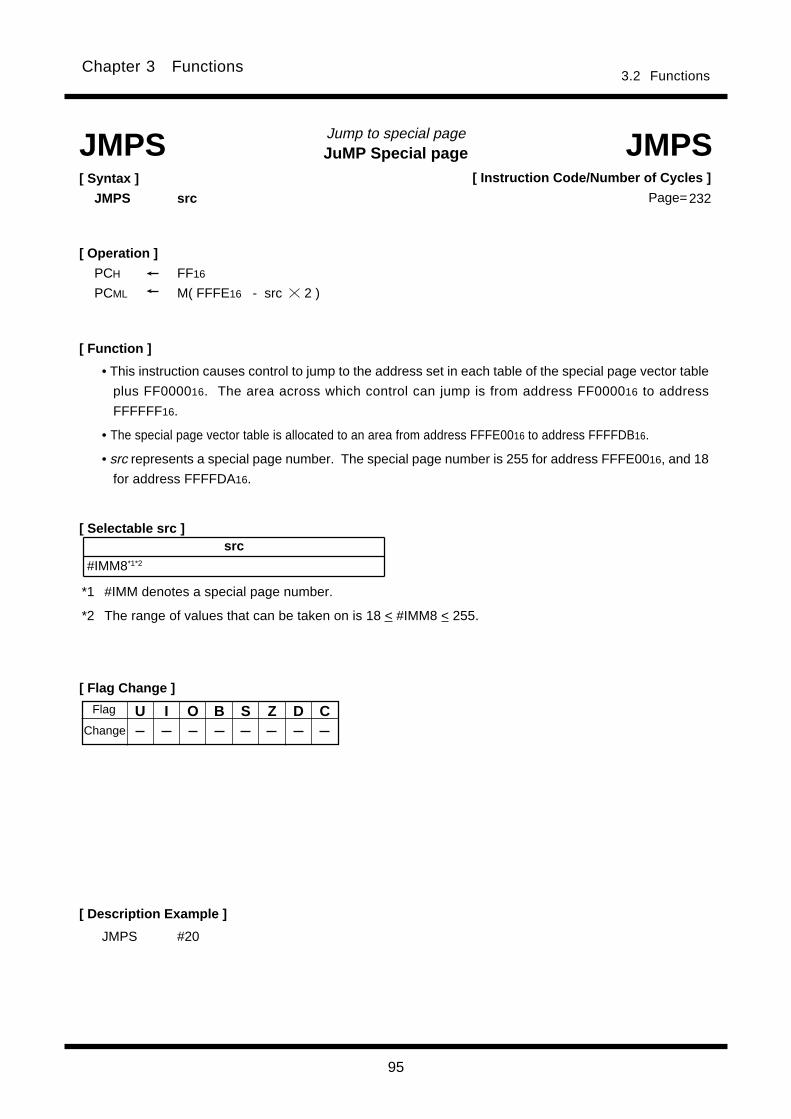
95
Chapter 3 Functions3.2 Functions
JuMP Special pageJump to special page
[ Syntax ]
JMPS src
JMPS JMPS
[ Operation ]
PCH FF16
PCML M( FFFE16 - src 2 )
*1 #IMM denotes a special page number.
*2 The range of values that can be taken on is 18 < #IMM8 < 255.
[ Selectable src ]
[ Description Example ]
JMPS #20
U I O B S Z D C
[ Flag Change ]
[ Instruction Code/Number of Cycles ]
Page=232
Flag
Change
[ Function ]
• This instruction causes control to jump to the address set in each table of the special page vector table
plus FF000016. The area across which control can jump is from address FF000016 to address
FFFFFF16.
• The special page vector table is allocated to an area from address FFFE0016 to address FFFFDB16.
• src represents a special page number. The special page number is 255 for address FFFE0016, and 18
for address FFFFDA16.
src
#IMM8*1*2
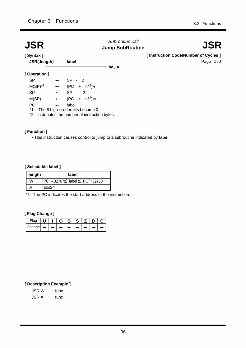
96
Chapter 3 Functions 3.2 Functions
Jump SubRoutineSubroutine call
[ Syntax ]
JSR(.length) label
[ Flag Change ]
[ Description Example ]
JSR JSR
JSR.W func
JSR.A func
[ Function ]• This instruction causes control to jump to a subroutine indicated by label .
[ Selectable label ]
.length label
.W PC*1 - 32767 label PC*1+32768
.A abs24
W , A
U I O B S Z D C
*1 The PC indicates the start address of the instruction.
[ Instruction Code/Number of Cycles ]
Page= 233
Flag
Change
[ Operation ]
SP SP - 2
M(SP)*1 (PC + n*2)H
SP SP - 2
M(SP) (PC + n*2)ML
PC label*1 The 8 high-oreder bits become 0.*2 n denotes the number of instruction bytes.
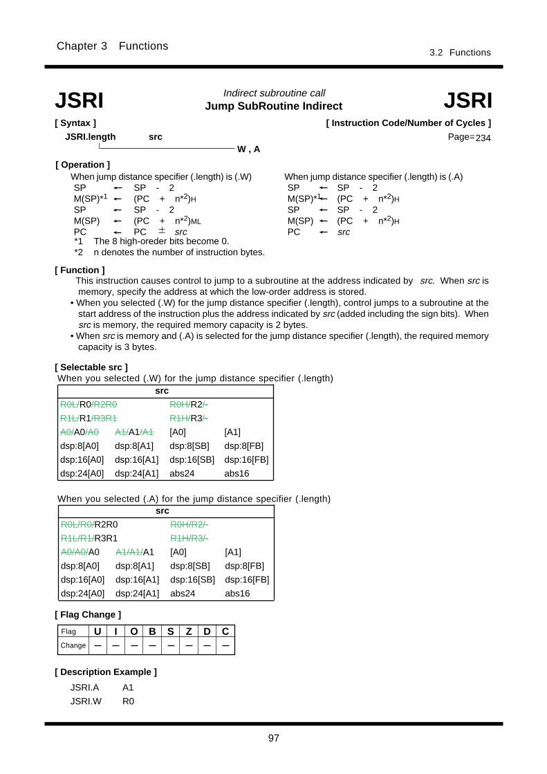
97
Chapter 3 Functions3.2 Functions
U I O B S Z D C
Indirect subroutine call
W , A
Jump SubRoutine Indirect JSRI
234
[ Instruction Code/Number of Cycles ]
Page=
[ Syntax ]
JSRI.length src
JSRI
JSRI.A A1
JSRI.W R0
[ Description Example ]
[ Selectable src ]
[ Flag Change ]
Flag
Change
When you selected (.W) for the jump distance specifier (.length)
When you selected (.A) for the jump distance specifier (.length)
[ Function ]
*1 The 8 high-oreder bits become 0.*2 n denotes the number of instruction bytes.
This instruction causes control to jump to a subroutine at the address indicated by src. When src ismemory, specify the address at which the low-order address is stored.
• When you selected (.W) for the jump distance specifier (.length), control jumps to a subroutine at thestart address of the instruction plus the address indicated by src (added including the sign bits). Whensrc is memory, the required memory capacity is 2 bytes.
• When src is memory and (.A) is selected for the jump distance specifier (.length), the required memorycapacity is 3 bytes.
[ Operation ] When jump distance specifier (.length) is (.W) When jump distance specifier (.length) is (.A)
SP SP - 2 SP SP - 2M(SP)*1 (PC + n*2)H M(SP)*1 (PC + n*2)HSP SP - 2 SP SP - 2M(SP) (PC + n*2)ML M(SP) (PC + n*2)HPC PC src PC src
src
R0L/R0/R2R0 R0H/R2/-
R1L/R1/R3R1 R1H/R3/-
A0/A0/A0 A1/A1/A1 [A0] [A1]
dsp:8[A0] dsp:8[A1] dsp:8[SB] dsp:8[FB]
dsp:16[A0] dsp:16[A1] dsp:16[SB] dsp:16[FB]
dsp:24[A0] dsp:24[A1] abs24 abs16
src
R0L/R0/R2R0 R0H/R2/-
R1L/R1/R3R1 R1H/R3/-
A0/A0/A0 A1/A1/A1 [A0] [A1]
dsp:8[A0] dsp:8[A1] dsp:8[SB] dsp:8[FB]
dsp:16[A0] dsp:16[A1] dsp:16[SB] dsp:16[FB]
dsp:24[A0] dsp:24[A1] abs24 abs16
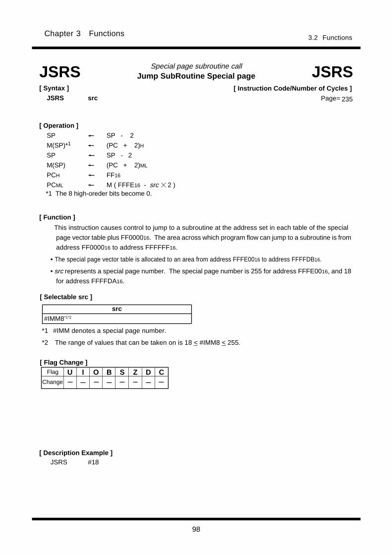
98
Chapter 3 Functions 3.2 Functions
Jump SubRoutine Special pageSpecial page subroutine callJSRS JSRS
[ Syntax ]
JSRS src
[ Function ]
This instruction causes control to jump to a subroutine at the address set in each table of the special
page vector table plus FF000016. The area across which program flow can jump to a subroutine is from
address FF000016 to address FFFFFF16.
• The special page vector table is allocated to an area from address FFFE0016 to address FFFFDB16.
• src represents a special page number. The special page number is 255 for address FFFE0016, and 18
for address FFFFDA16.
[ Operation ]
SP SP - 2
M(SP)*1 (PC + 2)H
SP SP - 2
M(SP) (PC + 2)ML
PCH FF16
PCML M ( FFFE16 - src 2 )*1 The 8 high-oreder bits become 0.
[ Flag Change ]
[ Selectable src ]
src
#IMM8*1*2
*1 #IMM denotes a special page number.
*2 The range of values that can be taken on is 18 < #IMM8 < 255.
[ Description Example ]JSRS #18
[ Instruction Code/Number of Cycles ]
Page= 235
U I O B S Z D CFlag
Change
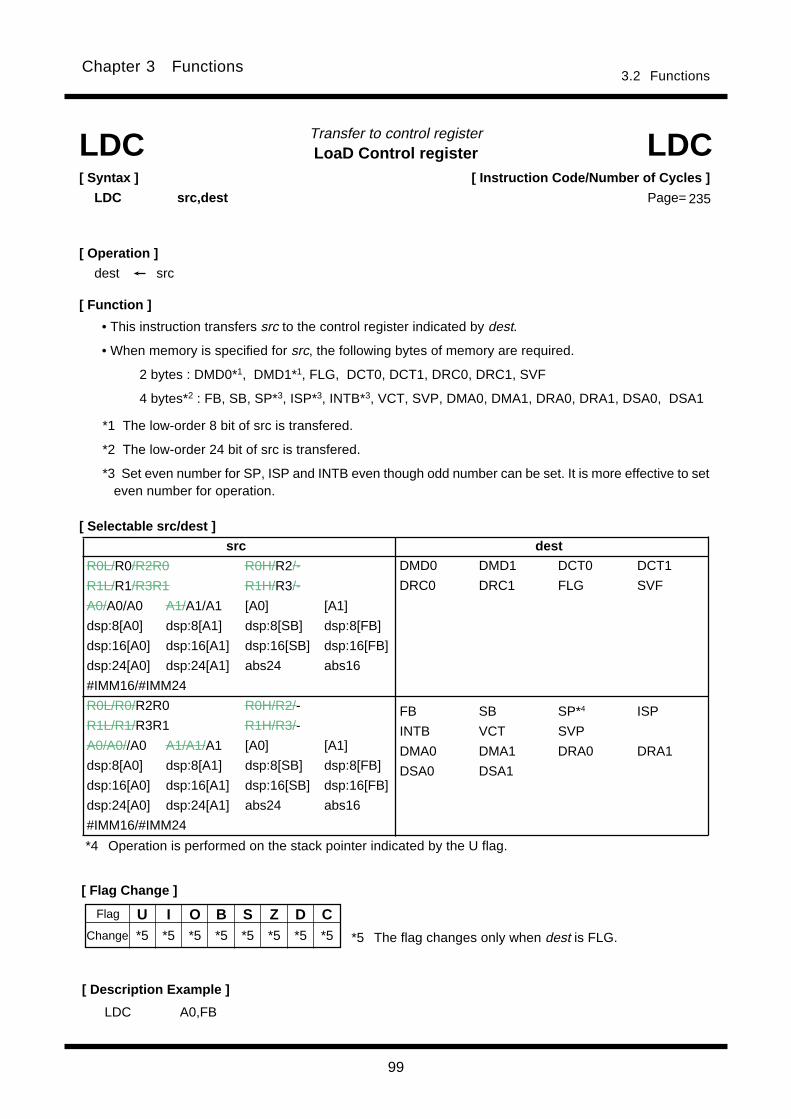
99
Chapter 3 Functions3.2 Functions
LoaD Control registerTransfer to control register
[ Selectable src/dest ]
[ Function ]
LDC LDC[ Syntax ]
LDC src,dest
• This instruction transfers src to the control register indicated by dest.
• When memory is specified for src, the following bytes of memory are required.
2 bytes : DMD0*1, DMD1*1, FLG, DCT0, DCT1, DRC0, DRC1, SVF
4 bytes*2 : FB, SB, SP*3, ISP*3, INTB*3, VCT, SVP, DMA0, DMA1, DRA0, DRA1, DSA0, DSA1
[ Operation ]
dest src
[ Instruction Code/Number of Cycles ]
Page= 235
src dest
R0L/R0/R2R0 R0H/R2/-
R1L/R1/R3R1 R1H/R3/-
A0/A0/A0 A1/A1/A1 [A0] [A1]
dsp:8[A0] dsp:8[A1] dsp:8[SB] dsp:8[FB]
dsp:16[A0] dsp:16[A1] dsp:16[SB] dsp:16[FB]
dsp:24[A0] dsp:24[A1] abs24 abs16
#IMM16/#IMM24
R0L/R0/R2R0 R0H/R2/-
R1L/R1/R3R1 R1H/R3/-
A0/A0//A0 A1/A1/A1 [A0] [A1]
dsp:8[A0] dsp:8[A1] dsp:8[SB] dsp:8[FB]
dsp:16[A0] dsp:16[A1] dsp:16[SB] dsp:16[FB]
dsp:24[A0] dsp:24[A1] abs24 abs16
#IMM16/#IMM24
DMD0 DMD1 DCT0 DCT1
DRC0 DRC1 FLG SVF
*1 The low-order 8 bit of src is transfered.
*2 The low-order 24 bit of src is transfered.
*3 Set even number for SP, ISP and INTB even though odd number can be set. It is more effective to seteven number for operation.
FB SB SP*4 ISP
INTB VCT SVP
DMA0 DMA1 DRA0 DRA1
DSA0 DSA1
[ Flag Change ]
[ Description Example ]
LDC A0,FB
U I O B S Z D C*5 *5 *5 *5 *5 *5 *5 *5 *5 The flag changes only when dest is FLG.
*4 Operation is performed on the stack pointer indicated by the U flag.
Flag
Change

100
Chapter 3 Functions 3.2 Functions
Register information for the task whose task number = 0.
(See the above diagram.)
SP correction value for the task whose task number = 0.
Register information for the task whose task number = 1.
(See the above diagram.)
SP correction value for the task whose task number = 1.
Register information for the task whose task number = n*1.
(See the above diagram.)
SP correction value for the task whose task number = n*1.
LoaD ConTeXtRestore contextLDCTX LDCTX
[ Syntax ]
LDCTX abs16,abs24
LDCTX Ram,Rom_TBL[ Description Example ]
[ Flag Change ]
U I O B S Z D C
[ Instruction Code/Number of Cycles ]
Page=238
Flag
Change
[ Function ]• This instruction restores task context from the stack area.• Set the RAM address that contains the task number in abs16 and the start address of table data in abs24.• The required register information is specified from table data by the task number and the data in the stack area is
transferred to each register according to the specified register information. Then the SP correction value isadded to the stack pointer (SP). For this SP correction value, set the number of bytes you want to the trans-ferred. Calculated as 2 bytes when transferring the R0, R1, R2, or R3 registers. A0, A1, SB, and FBare calculated as 4 bytes.
• Information on transferred registers is configured as shown below. Logic 1 indicates a register to betransferred and logic 0 indicates a register that is not transferred.
FB SB A1 A0 R3 R2 R1 R0
LSBMSB
Transferred sequentially beginningwith R0
• The table data is comprised as shown below. The address indicated by abs24 is the base address ofthe table. The data stored at an address apart from the base address as much as twice the content ofabs16 indicates register information, and the next address contains the stack pointer correction value.
abs24 Base addressof table
Direction inwhich addressincreases
abs16 2
*1 n=0 to 255

101
Chapter 3 Functions3.2 Functions
LoaD Interrupt Permission LevelSet interrupt enable level
[ Syntax ]
LDIPL src
[ Flag Change ]
[ Description Example ]LDIPL #2
LDIPL LDIPL
[ Function ]
[ Selectable src ]
src
#IMM3*1
• This instruction transfers src to IPL.
[ Operation ]
IPL src
U I O B S Z D C
*1 The range of values that can be taken on is 0 < #IMM3 < 7.
[ Instruction Code/Number of Cycles ]
Page= 239
Flag
Change

102
3.2 FunctionsChapter 3 Functions
MAX selectSelect maximum value
[ Description Example ]
[ Function ]
MAX MAX[ Syntax ]
MAX.size src,dest
MAX.B #0ABH,R0L
MAX.W #-1,R2
B , W
[ Operation ]
if (src > dest)
then dest src
• Singed compares src and dest and transfers src to dest when src is greater than dest. No change
occurs when src is smaller than or equal to dest.
• When (.W) is specified for the size specifier (.size), dest is the address register and writing to dest, the8 high-order bits of the operation result are become 0. Also, when src is the address register, trans-fers the 16 low-order bits of the address register to dest.
[ Instruction Code/Number of Cycles ]
Page=
[ Flag Change ]
U I O B S Z D CFlag
Change
[ Selectable src/dest ]
src dest
R0L/R0/R2R0 R0H/R2/-
R1L/R1/R3R1 R1H/R3/-
A0/A0/A0 A1/A1/A1 [A0] [A1]
dsp:8[A0] dsp:8[A1] dsp:8[SB] dsp:8[FB]
dsp:16[A0] dsp:16[A1] dsp:16[SB] dsp:16[FB]
dsp:24[A0] dsp:24[A1] abs24 abs16
#IMM8/#IMM16
R0L/R0/R2R0 R0H/R2/-
R1L/R1/R3R1 R1H/R3/-
A0/A0/A0 A1/A1/A1 [A0] [A1]
dsp:8[A0] dsp:8[A1] dsp:8[SB] dsp:8[FB]
dsp:16[A0] dsp:16[A1] dsp:16[SB] dsp:16[FB]
dsp:24[A0] dsp:24[A1] abs24 abs16
239
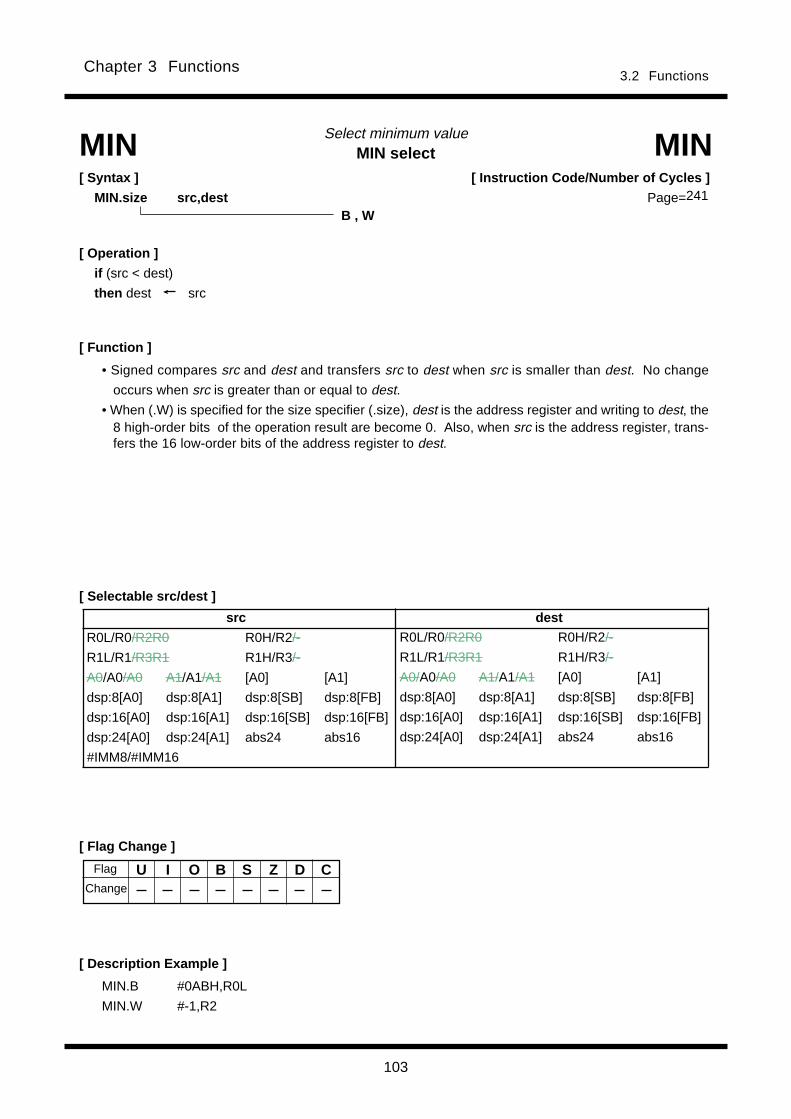
103
3.2 FunctionsChapter 3 Functions
MIN selectSelect minimum value
[ Function ]
MIN MIN[ Syntax ]
MIN.size src,destB , W
[ Operation ]
if (src < dest)
then dest src
• Signed compares src and dest and transfers src to dest when src is smaller than dest. No change
occurs when src is greater than or equal to dest.
• When (.W) is specified for the size specifier (.size), dest is the address register and writing to dest, the8 high-order bits of the operation result are become 0. Also, when src is the address register, trans-fers the 16 low-order bits of the address register to dest.
[ Instruction Code/Number of Cycles ]
Page=
[ Description Example ]
MIN.B #0ABH,R0L
MIN.W #-1,R2
[ Flag Change ]
U I O B S Z D CFlag
Change
[ Selectable src/dest ]
src dest
R0L/R0/R2R0 R0H/R2/-
R1L/R1/R3R1 R1H/R3/-
A0/A0/A0 A1/A1/A1 [A0] [A1]
dsp:8[A0] dsp:8[A1] dsp:8[SB] dsp:8[FB]
dsp:16[A0] dsp:16[A1] dsp:16[SB] dsp:16[FB]
dsp:24[A0] dsp:24[A1] abs24 abs16
#IMM8/#IMM16
R0L/R0/R2R0 R0H/R2/-
R1L/R1/R3R1 R1H/R3/-
A0/A0/A0 A1/A1/A1 [A0] [A1]
dsp:8[A0] dsp:8[A1] dsp:8[SB] dsp:8[FB]
dsp:16[A0] dsp:16[A1] dsp:16[SB] dsp:16[FB]
dsp:24[A0] dsp:24[A1] abs24 abs16
241

104
3.2 FunctionsChapter 3 Functions
MOVeTransfer
[ Description Example ]
[ Selectable src/dest ]* 1
[ Function ]
MOV MOV[ Syntax ]
MOV.size (:format) src,dest
(See the next page for src/dest classified by format.)
MOV.B:S #0ABH,R0LMOV.W #-1,R2MOV.W [A1],[[A2]]
G , Q , Z , S (Can be specified)B , W , L
[ Operation ]
dest src [dest] src
dest [src] [dest] [src]
• This instruction transfers src to dest.
• When (.B) is specified for the size specifier (.size) and dest is the address register (A0, A1), src is zero-extended to perform operation in 16 bits. In this case, the 8 high-oreder bits become 0. Also, when srcis the address register, the 8 low-order bits of the address register are used as data to be operated on.
• When (.W) is specified for the size specifier (.size) and dest is the address register, the 8 high-orderbits become 0. Also, when src is the address register, the 16 low-order bits of the address register arethe data to be operated on.
• When (.L) is specified for the size specifier (.size) and dest is the address register, the 8 high-order bitsof src is ignored and the 24 low-order bits of src is stored to dest. Also, when src is the addressregister, src is zero-extended to perform operation in 32 bits. The flags also change states dependingon the result of 32-bit operation.
[ Instruction Code/Number of Cycles ]
Page=
[ Flag Change ]
U I O B S Z D C
ConditionsS : The flag is set when the transfer resulted in MSB = 1; otherwise cleared.Z : The flag is set when the transfer resulted in 0; otherwise cleared.
Flag
Change
*1 Indirect addressing [src] and [dest] can be used in all addressing except R0L/R0/R2R0, R0H/R2/-, R1L/R1/R3R1,R1H/R3/-, SP/SP/SP, dsp:8[SP], and #IMM.
*2 When you specify (.B) for the size specifier (.size), you cannot choose A0 and/or A1 for src and destsimultaneously.
*3 When src or dest is dsp:8[SP], you cannot choose indirect addressing [src] or [dest] neither.
src dest
R0L/R0/R2R0 R0H/R2/-
R1L/R1/R3R1 R1H/R3/-
A0/A0/A0*2 A1/A1/A1*2 [A0] [A1]
dsp:8[A0] dsp:8[A1] dsp:8[SB] dsp:8[FB]
dsp:16[A0] dsp:16[A1] dsp:16[SB] dsp:16[FB]
dsp:24[A0] dsp:24[A1] abs24 abs16
#IMM dsp:8[SP]*3
R0L/R0/R2R0 R0H/R2/-
R1L/R1/R3R1 R1H/R3/-
A0/A0/A0*2 A1/A1/A1*2 [A0] [A1]
dsp:8[A0] dsp:8[A1] dsp:8[SB] dsp:8[FB]
dsp:16[A0] dsp:16[A1] dsp:16[SB] dsp:16[FB]
dsp:24[A0] dsp:24[A1] abs24 abs16
dsp:8[SP]*3
243

105
3.2 FunctionsChapter 3 Functions
[src/dest Classified by Format]
G format * 1
Z format * 15
S format * 9
*9 Indirect addressing [src] and [dest] can be used in all addressing except R0L/R0/R2R0, R0H/R2/-, R1L/R1/R3R1,R1H/R3/-, dsp:8[SP], and #IMM.
*10 You cannot choose the same registers for src and dest simultaneously.*11 You can only specify (.B) or (.W) for the size specifier (.size).*12 When src is not #IMM8/IMM16, you can only choose R1L/R1 for dest .*13 You can specify (.W) for the size specifier (.size). In this case, you cannot use indirect addressing mode for dest.*14 You can specify (.L) for the size specifier (.size). In this case, you cannot use indirect addressing mode for dest.
Q format * 6*7
*6 Indirect addressing [src] and [dest] can be used in all addressing except R0L/R0/R2R0, R0H/R2/-, R1L/R1/R3R1,R1H/R3/-, dsp:8[SP], and #IMM.
*7 You can only specify (.B) or (.W) for the size specifier (.size).*8 The range of values that can be taken on is - 8 < #IMM4 < +7.
*1 Indirect addressing [src] and [dest] can be used in all addressing except R0L/R0/R2R0, R0H/R2/-, R1L/R1/R3R1,R1H/R3/-, SP/SP/SP, dsp:8[SP], and #IMM.
*2 When you specify (.B) for the size specifier (.size), you cannot choose A0 and/or A1 for src and destsimultaneously.
*3 Operation is performed on the stack pointer indicated by the U flag. You cannot choose dsp:8 [SP] forsrc and dest simultaneously.
*4 When you specify (.B) or (.W) for the size specifier (.size) and src is not #IMM, you can choose dsp:8 [SP] for dest.*5 When src or dest is dsp:8[SP], you cannot choose indirect addressing [src] or [dest] neither.
src dest
R0L R0H dsp:8[SB] dsp:8[FB] R0L/R0 dsp:8[SB] dsp:8[FB] abs16
abs16 #0 A0 A1
src dest
R0L/R0*10*11 dsp:8[SB]*11dsp:8[FB]*11 abs16*11 R0L/R0*10*11 R1L/R1*11*12 dsp:8[SB]*11dsp:8[FB]*11
#IMM8/#IMM16*11 abs16*11 A0 A1
R0L/R0 dsp:8[SB]*14dsp:8[FB]*14 abs16*14 R0L R0H dsp:8[SB] dsp:8[FB]
#IMM16*13/#IMM24*14 abs16 A0/A0*13/A0*14 A1/A1*13/A1*14
src dest
R0L/R0/R2R0 R0H/R2/-
R1L/R1/R3R1 R1H/R3/-
A0/A0/A0*2 A1/A1/A1*2 [A0] [A1]
dsp:8[A0] dsp:8[A1] dsp:8[SB] dsp:8[FB]
dsp:16[A0] dsp:16[A1] dsp:16[SB] dsp:16[FB]
dsp:24[A0] dsp:24[A1] abs24 abs16
#IMM8/#IMM16/#IMM32 dsp:8[SP]*3*5
R0L/R0/R2R0 R0H/R2/-
R1L/R1/R3R1 R1H/R3/-
A0/A0/A0*2 A1/A1/A1*2 [A0] [A1]
dsp:8[A0] dsp:8[A1] dsp:8[SB] dsp:8[FB]
dsp:16[A0] dsp:16[A1] dsp:16[SB] dsp:16[FB]
dsp:24[A0] dsp:24[A1] abs24 abs16
dsp:8[SP]*3*4*5
src dest
R0L/R0/R2R0 R0H/R2/-
R1L/R1/R3R1 R1H/R3/-
A0/A0/A0 A1/A1/A1 [A0] [A1]
dsp:8[A0] dsp:8[A1] dsp:8[SB] dsp:8[FB]
dsp:16[A0] dsp:16[A1] dsp:16[SB] dsp:16[FB]
dsp:24[A0] dsp:24[A1] abs24 abs16
#IMM4*8
R0L/R0/R2R0 R0H/R2/-
R1L/R1/R3R1 R1H/R3/-
A0/A0/A0 A1/A1/A1 [A0] [A1]
dsp:8[A0] dsp:8[A1] dsp:8[SB] dsp:8[FB]
dsp:16[A0] dsp:16[A1] dsp:16[SB] dsp:16[FB]
dsp:24[A0] dsp:24[A1] abs24 abs16
*15 You can specify (.B) or (.W) for the size specifier (.size).
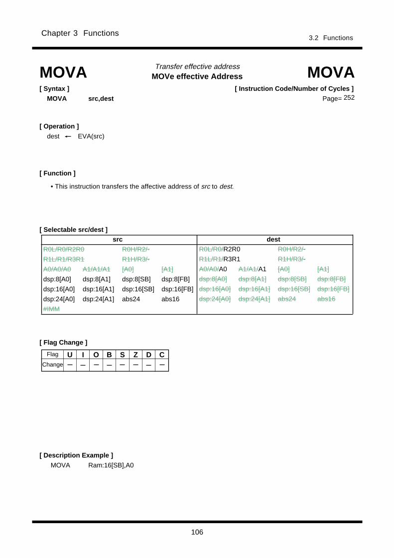
106
3.2 FunctionsChapter 3 Functions
MOVe effective AddressTransfer effective address
[ Flag Change ]
[ Description Example ]
[ Function ]
[ Selectable src/dest ]
MOVA MOVA[ Syntax ]
MOVA src,dest
[ Operation ]
dest EVA(src)
U I O B S Z D C
• This instruction transfers the affective address of src to dest.
MOVA Ram:16[SB],A0
[ Instruction Code/Number of Cycles ]
Page=
Flag
Change
src dest
R0L/R0/R2R0 R0H/R2/-
R1L/R1/R3R1 R1H/R3/-
A0/A0/A0 A1/A1/A1 [A0] [A1]
dsp:8[A0] dsp:8[A1] dsp:8[SB] dsp:8[FB]
dsp:16[A0] dsp:16[A1] dsp:16[SB] dsp:16[FB]
dsp:24[A0] dsp:24[A1] abs24 abs16
#IMM
R0L/R0/R2R0 R0H/R2/-
R1L/R1/R3R1 R1H/R3/-
A0/A0/A0 A1/A1/A1 [A0] [A1]
dsp:8[A0] dsp:8[A1] dsp:8[SB] dsp:8[FB]
dsp:16[A0] dsp:16[A1] dsp:16[SB] dsp:16[FB]
dsp:24[A0] dsp:24[A1] abs24 abs16
252
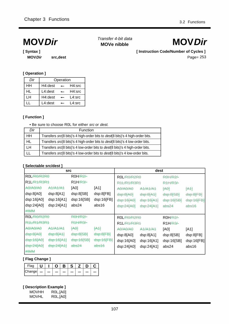
107
3.2 FunctionsChapter 3 Functions
MOVe nibbleTransfer 4-bit dataMOVDir MOVDir
[ Operation ]
[ Syntax ]
MOVDir src,dest
[ Description Example ]
Dir Operation
HH H4:dest H4:src
HL L4:dest H4:src
LH H4:dest L4:src
LL L4:dest L4:src
[ Function ]
Dir Function
HH Transfers src(8 bits)'s 4 high-order bits to dest(8 bits)'s 4 high-order bits.
HL Transfers src(8 bits)'s 4 high-order bits to dest(8 bits)'s 4 low-order bits.
LH Transfers src(8 bits)'s 4 low-order bits to dest(8 bits)'s 4 high-order bits.
LL Transfers src(8 bits)'s 4 low-order bits to dest(8 bits)'s 4 low-order bits.
[ Selectable src/dest ]
[ Flag Change ]
U I O B S Z D C
MOVHH R0L,[A0]MOVHL R0L,[A0]
[ Instruction Code/Number of Cycles ]
Page=
• Be sure to choose R0L for either src or dest.
Flag
Change
src dest
R0L/R0/R2R0 R0H/R2/-
R1L/R1/R3R1 R1H/R3/-
A0/A0/A0 A1/A1/A1 [A0] [A1]
dsp:8[A0] dsp:8[A1] dsp:8[SB] dsp:8[FB]
dsp:16[A0] dsp:16[A1] dsp:16[SB] dsp:16[FB]
dsp:24[A0] dsp:24[A1] abs24 abs16
#IMM
R0L/R0/R2R0 R0H/R2/-
R1L/R1/R3R1 R1H/R3/-
A0/A0/A0 A1/A1/A1 [A0] [A1]
dsp:8[A0] dsp:8[A1] dsp:8[SB] dsp:8[FB]
dsp:16[A0] dsp:16[A1] dsp:16[SB] dsp:16[FB]
dsp:24[A0] dsp:24[A1] abs24 abs16
#IMM
R0L/R0/R2R0 R0H/R2/-
R1L/R1/R3R1 R1H/R3/-
A0/A0/A0 A1/A1/A1 [A0] [A1]
dsp:8[A0] dsp:8[A1] dsp:8[SB] dsp:8[FB]
dsp:16[A0] dsp:16[A1] dsp:16[SB] dsp:16[FB]
dsp:24[A0] dsp:24[A1] abs24 abs16
R0L/R0/R2R0 R0H/R2/-
R1L/R1/R3R1 R1H/R3/-
A0/A0/A0 A1/A1/A1 [A0] [A1]
dsp:8[A0] dsp:8[A1] dsp:8[SB] dsp:8[FB]
dsp:16[A0] dsp:16[A1] dsp:16[SB] dsp:16[FB]
dsp:24[A0] dsp:24[A1] abs24 abs16
253

108
3.2 FunctionsChapter 3 Functions
MOVe eXtend signTransfer extend sign
[ Description Example ]
[ Function ]
[ Selectable src/dest ]
MOVX MOVX[ Syntax ]
MOVX src,dest
[ Operation ]
dest/[dest] EXTS(src)
• Sign-extends the 8-bit immdiate to 32 bits before transferring it to dest.
• When dest is the address register (A0, A1), the 24 low-order bits are transferred. The flags also
change state for the 32 bits transfers performed.
MOVX #10,A0MOVX #5,[[A1]]
[ Instruction Code/Number of Cycles ]
Page=
src dest *1
R0L/R0/R2R0 R0H/R2/-
R1L/R1/R3R1 R1H/R3/-
A0/A0/A0 A1/A1/A1 [A0] [A1]
dsp:8[A0] dsp:8[A1] dsp:8[SB] dsp:8[FB]
dsp:16[A0] dsp:16[A1] dsp:16[SB] dsp:16[FB]
dsp:24[A0] dsp:24[A1] abs24 abs16
#IMM8*2
R0L/R0/R2R0 R0H/R2/-
R1L/R1/R3R1 R1H/R3/-
A0/A0/A0 A1/A1/A1 [A0] [A1]
dsp:8[A0] dsp:8[A1] dsp:8[SB] dsp:8[FB]
dsp:16[A0] dsp:16[A1] dsp:16[SB] dsp:16[FB
dsp:24[A0] dsp:24[A1] abs24 abs16
[ Flag Change ]
U I O B S Z D C
ConditionsS : The flag is set when the transfer resulted in MSB of dest = 1; otherwise cleared.Z : The flag is set when the transfer resulted in 0; otherwise cleared.
Flag
Change
*1 Indirect addressing [dest] can be used in all addressing except R0L/R0/R2R0, R0H/R2/-, R1L/R1/R3R1,R1H/R3/-, SP/SP/SP, dsp:8[SP], and #IMM.
*2 The range of values that can be taken on is -128 < #IMM8 < +127
255
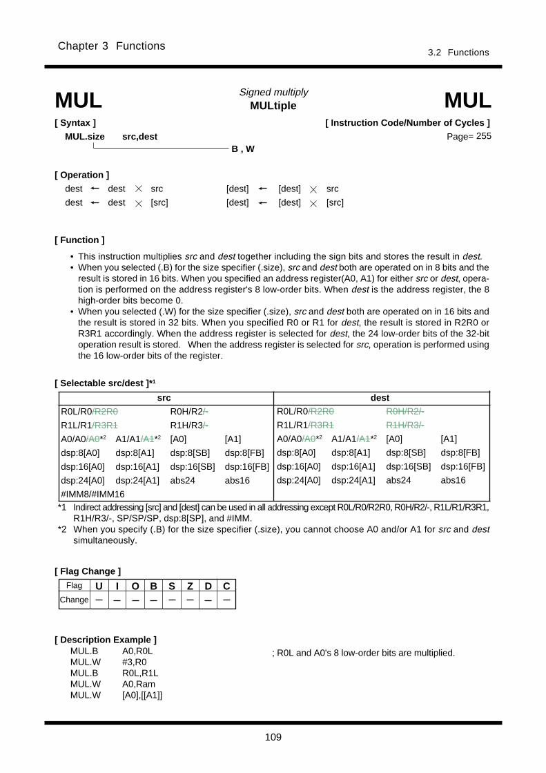
109
3.2 FunctionsChapter 3 Functions
MULtipleSigned multiply
[ Syntax ]
MUL.size src,dest
[ Description Example ]
[ Function ]
MUL MUL
B , W
[ Operation ]
dest dest src [dest] [dest] src
dest dest [src] [dest] [dest] [src]
• This instruction multiplies src and dest together including the sign bits and stores the result in dest.• When you selected (.B) for the size specifier (.size), src and dest both are operated on in 8 bits and the
result is stored in 16 bits. When you specified an address register(A0, A1) for either src or dest, opera-tion is performed on the address register's 8 low-order bits. When dest is the address register, the 8high-order bits become 0.
• When you selected (.W) for the size specifier (.size), src and dest both are operated on in 16 bits andthe result is stored in 32 bits. When you specified R0 or R1 for dest, the result is stored in R2R0 orR3R1 accordingly. When the address register is selected for dest, the 24 low-order bits of the 32-bitoperation result is stored. When the address register is selected for src, operation is performed usingthe 16 low-order bits of the register.
MUL.B A0,R0LMUL.W #3,R0MUL.B R0L,R1LMUL.W A0,RamMUL.W [A0],[[A1]]
[ Selectable src/dest ]* 1
[ Flag Change ]
U I O B S Z D C
[ Instruction Code/Number of Cycles ]
Page=
Flag
Change
; R0L and A0's 8 low-order bits are multiplied.
src dest
R0L/R0/R2R0 R0H/R2/-
R1L/R1/R3R1 R1H/R3/-
A0/A0/A0*2 A1/A1/A1*2 [A0] [A1]
dsp:8[A0] dsp:8[A1] dsp:8[SB] dsp:8[FB]
dsp:16[A0] dsp:16[A1] dsp:16[SB] dsp:16[FB]
dsp:24[A0] dsp:24[A1] abs24 abs16
#IMM8/#IMM16
R0L/R0/R2R0 R0H/R2/-
R1L/R1/R3R1 R1H/R3/-
A0/A0/A0*2 A1/A1/A1*2 [A0] [A1]
dsp:8[A0] dsp:8[A1] dsp:8[SB] dsp:8[FB]
dsp:16[A0] dsp:16[A1] dsp:16[SB] dsp:16[FB]
dsp:24[A0] dsp:24[A1] abs24 abs16
*1 Indirect addressing [src] and [dest] can be used in all addressing except R0L/R0/R2R0, R0H/R2/-, R1L/R1/R3R1,R1H/R3/-, SP/SP/SP, dsp:8[SP], and #IMM.
*2 When you specify (.B) for the size specifier (.size), you cannot choose A0 and/or A1 for src and destsimultaneously.
255
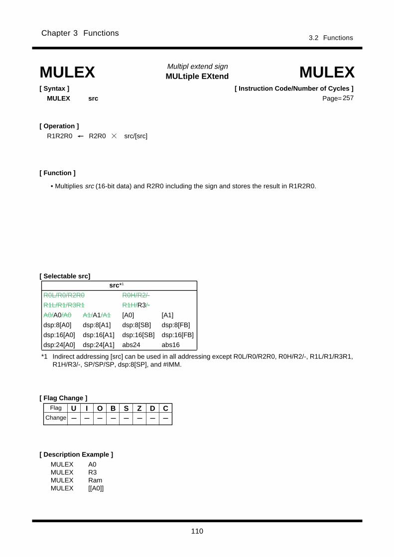
110
3.2 FunctionsChapter 3 Functions
MULtiple EXtendMultipl extend sign
[ Description Example ]
[ Syntax ]
MULEX src
MULEX MULEX
[ Operation ]
R1R2R0 R2R0 src/[src]
[ Function ]
MULEX A0MULEX R3MULEX RamMULEX [[A0]]
U I O B S Z D C
• Multiplies src (16-bit data) and R2R0 including the sign and stores the result in R1R2R0.
[ Instruction Code/Number of Cycles ]
Page=
[ Selectable src]
[ Flag Change ]Flag
Change
*1 Indirect addressing [src] can be used in all addressing except R0L/R0/R2R0, R0H/R2/-, R1L/R1/R3R1,R1H/R3/-, SP/SP/SP, dsp:8[SP], and #IMM.
src *1
R0L/R0/R2R0 R0H/R2/-
R1L/R1/R3R1 R1H/R3/-
A0/A0/A0 A1/A1/A1 [A0] [A1]
dsp:8[A0] dsp:8[A1] dsp:8[SB] dsp:8[FB]
dsp:16[A0] dsp:16[A1] dsp:16[SB] dsp:16[FB]
dsp:24[A0] dsp:24[A1] abs24 abs16
257
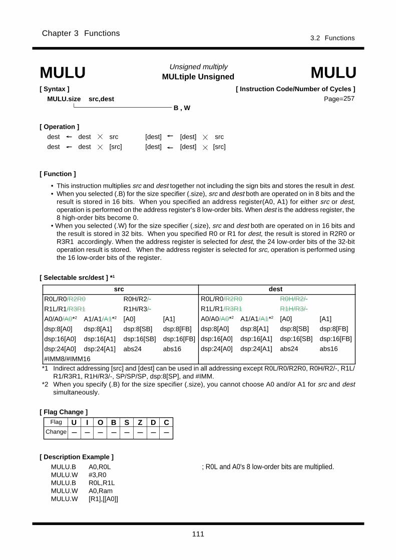
111
3.2 FunctionsChapter 3 Functions
MULtiple UnsignedUnsigned multiply
[ Description Example ]
[ Syntax ]
MULU.size src,dest
MULU MULU
B , W
[ Operation ]
dest dest src [dest] [dest] src
dest dest [src] [dest] [dest] [src]
[ Function ]
MULU.B A0,R0L ; R0L and A0's 8 low-order bits are multiplied.MULU.W #3,R0MULU.B R0L,R1LMULU.W A0,RamMULU.W [R1],[[A0]]
U I O B S Z D C
• This instruction multiplies src and dest together not including the sign bits and stores the result in dest.• When you selected (.B) for the size specifier (.size), src and dest both are operated on in 8 bits and the
result is stored in 16 bits. When you specified an address register(A0, A1) for either src or dest,operation is performed on the address register's 8 low-order bits. When dest is the address register, the8 high-order bits become 0.
• When you selected (.W) for the size specifier (.size), src and dest both are operated on in 16 bits andthe result is stored in 32 bits. When you specified R0 or R1 for dest, the result is stored in R2R0 orR3R1 accordingly. When the address register is selected for dest, the 24 low-order bits of the 32-bitoperation result is stored. When the address register is selected for src, operation is performed usingthe 16 low-order bits of the register.
[ Instruction Code/Number of Cycles ]
Page=
[ Selectable src/dest ] * 1
[ Flag Change ]Flag
Change
src dest
R0L/R0/R2R0 R0H/R2/-
R1L/R1/R3R1 R1H/R3/-
A0/A0/A0*2 A1/A1/A1*2 [A0] [A1]
dsp:8[A0] dsp:8[A1] dsp:8[SB] dsp:8[FB]
dsp:16[A0] dsp:16[A1] dsp:16[SB] dsp:16[FB]
dsp:24[A0] dsp:24[A1] abs24 abs16
#IMM8/#IMM16
R0L/R0/R2R0 R0H/R2/-
R1L/R1/R3R1 R1H/R3/-
A0/A0/A0*2 A1/A1/A1*2 [A0] [A1]
dsp:8[A0] dsp:8[A1] dsp:8[SB] dsp:8[FB]
dsp:16[A0] dsp:16[A1] dsp:16[SB] dsp:16[FB]
dsp:24[A0] dsp:24[A1] abs24 abs16
*1 Indirect addressing [src] and [dest] can be used in all addressing except R0L/R0/R2R0, R0H/R2/-, R1L/R1/R3R1, R1H/R3/-, SP/SP/SP, dsp:8[SP], and #IMM.
*2 When you specify (.B) for the size specifier (.size), you cannot choose A0 and/or A1 for src and destsimultaneously.
257
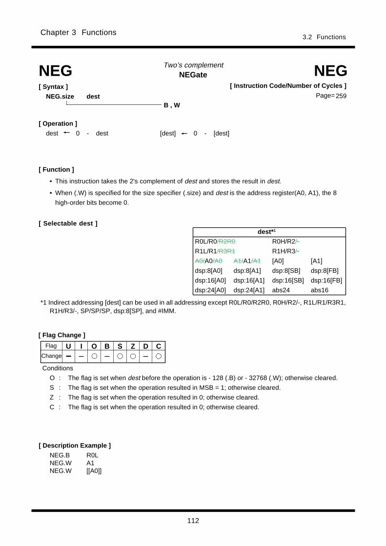
112
3.2 FunctionsChapter 3 Functions
NEGateTwo’s complement
[ Syntax ]
NEG.size dest
[ Flag Change ]
[ Description Example ]
[ Function ]
NEG NEG
B , W
[ Operation ]
dest 0 - dest [dest] 0 - [dest]
NEG.B R0LNEG.W A1NEG.W [[A0]]
U I O B S Z D C
Conditions
O : The flag is set when dest before the operation is - 128 (.B) or - 32768 (.W); otherwise cleared.
S : The flag is set when the operation resulted in MSB = 1; otherwise cleared.
Z : The flag is set when the operation resulted in 0; otherwise cleared.
C : The flag is set when the operation resulted in 0; otherwise cleared.
• This instruction takes the 2's complement of dest and stores the result in dest.
• When (.W) is specified for the size specifier (.size) and dest is the address register(A0, A1), the 8
high-order bits become 0.
[ Instruction Code/Number of Cycles ]
Page=
[ Selectable dest ]
Flag
Change
*1 Indirect addressing [dest] can be used in all addressing except R0L/R0/R2R0, R0H/R2/-, R1L/R1/R3R1,R1H/R3/-, SP/SP/SP, dsp:8[SP], and #IMM.
dest* 1
R0L/R0/R2R0 R0H/R2/-
R1L/R1/R3R1 R1H/R3/-
A0/A0/A0 A1/A1/A1 [A0] [A1]
dsp:8[A0] dsp:8[A1] dsp:8[SB] dsp:8[FB]
dsp:16[A0] dsp:16[A1] dsp:16[SB] dsp:16[FB]
dsp:24[A0] dsp:24[A1] abs24 abs16
259
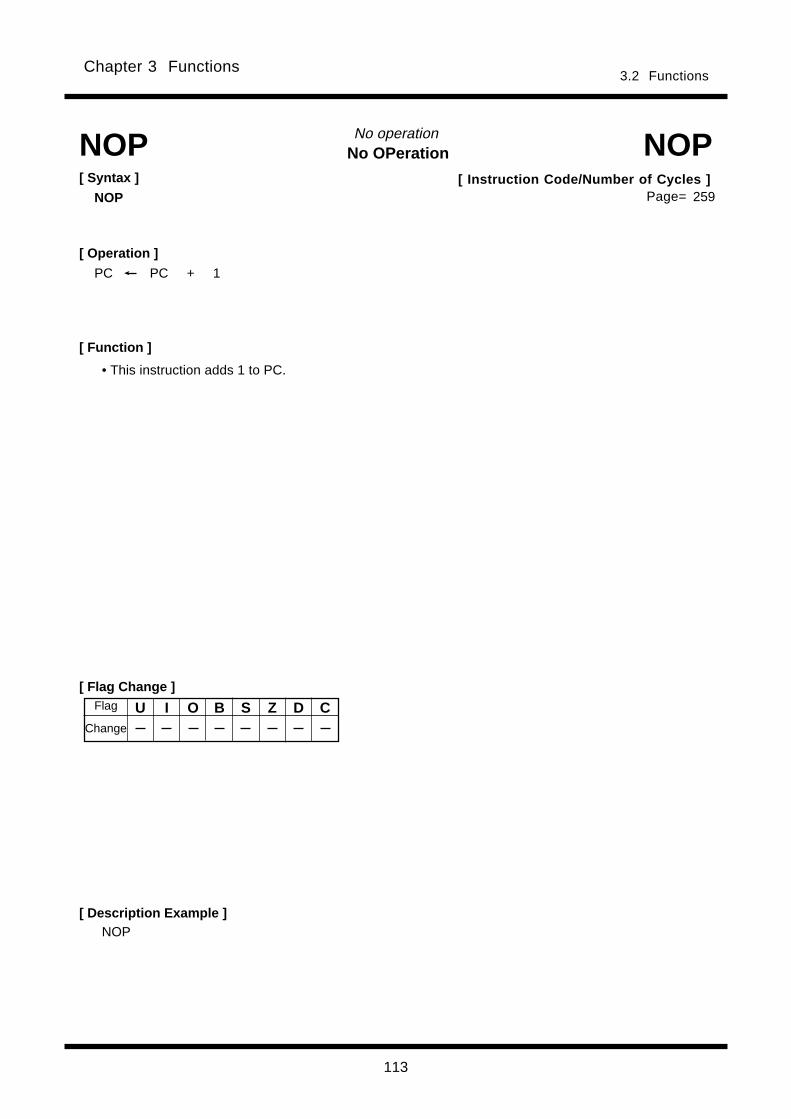
113
3.2 FunctionsChapter 3 Functions
No OPerationNo operation
[ Flag Change ]
[ Description Example ]NOP
[ Function ]
NOP NOP[ Syntax ]
NOP
• This instruction adds 1 to PC.
[ Operation ]
PC PC + 1
U I O B S Z D C
[ Instruction Code/Number of Cycles ]Page=
Flag
Change
259
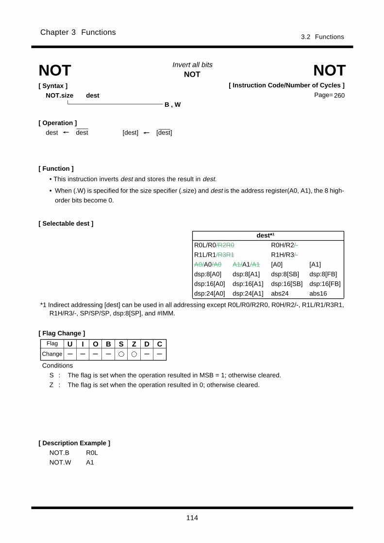
114
3.2 FunctionsChapter 3 Functions
NOTInvert all bitsNOT NOT
[ Operation ]
dest dest [dest] [dest]
[ Function ]
• This instruction inverts dest and stores the result in dest.
• When (.W) is specified for the size specifier (.size) and dest is the address register(A0, A1), the 8 high-
order bits become 0.
[ Selectable dest ]
[ Flag Change ]
[ Description Example ]
NOT.B R0L
NOT.W A1
B , W
Conditions
S : The flag is set when the operation resulted in MSB = 1; otherwise cleared.
Z : The flag is set when the operation resulted in 0; otherwise cleared.
[ Instruction Code/Number of Cycles ]
Page=[ Syntax ]
NOT.size dest
U I O B S Z D CFlag
Change
*1 Indirect addressing [dest] can be used in all addressing except R0L/R0/R2R0, R0H/R2/-, R1L/R1/R3R1,R1H/R3/-, SP/SP/SP, dsp:8[SP], and #IMM.
dest* 1
R0L/R0/R2R0 R0H/R2/-
R1L/R1/R3R1 R1H/R3/-
A0/A0/A0 A1/A1/A1 [A0] [A1]
dsp:8[A0] dsp:8[A1] dsp:8[SB] dsp:8[FB]
dsp:16[A0] dsp:16[A1] dsp:16[SB] dsp:16[FB]
dsp:24[A0] dsp:24[A1] abs24 abs16
260
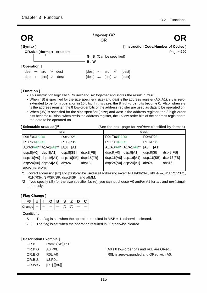
115
Chapter 3 Functions3.2 Functions
[ Instruction Code/Number of Cycles ]
Page=
ORLogically OR
[ Description Example ]OR.B Ram:8[SB],R0L
OR.B:G A0,R0L ; A0's 8 low-order bits and R0L are ORed.
OR.B:G R0L,A0 ; R0L is zero-expanded and ORed with A0.
OR.B:S #3,R0L
OR.W:G [R1],[[A0]]
[ Selectable src/dest ]* 1
• This instruction logically ORs dest and src together and stores the result in dest.• When (.B) is specified for the size specifier (.size) and dest is the address register (A0, A1), src is zero-
extended to perform operation in 16 bits. In this case, the 8 high-order bits become 0. Also, when srcis the address register, the 8 low-order bits of the address register are used as data to be operated on.
• When (.W) is specified for the size specifier (.size) and dest is the address register, the 8 high-orderbits become 0. Also, when src is the address register, the 16 low-order bits of the address register arethe data to be operated on.
[ Flag Change ]
OR OR[ Syntax ]
OR.size (:format) src,dest
[ Function ]
(See the next page for src/dest classified by format.)
G , S (Can be specified)
B , W[ Operation ]
dest src dest [dest] src [dest]
dest [src] dest [dest] [src] [dest]
U I O B S Z D C
Conditions
S : The flag is set when the operation resulted in MSB = 1; otherwise cleared.
Z : The flag is set when the operation resulted in 0; otherwise cleared.
260
Flag
Change
src dest
R0L/R0/R2R0 R0H/R2/-
R1L/R1/R3R1 R1H/R3/-
A0/A0/A0*2 A1/A1/A1*2 [A0] [A1]
dsp:8[A0] dsp:8[A1] dsp:8[SB] dsp:8[FB]
dsp:16[A0] dsp:16[A1] dsp:16[SB] dsp:16[FB]
dsp:24[A0] dsp:24[A1] abs24 abs16
#IMM8/#IMM16
R0L/R0/R2R0 R0H/R2/-
R1L/R1/R3R1 R1H/R3/-
A0/A0/A0*2 A1/A1/A1*2 [A0] [A1]
dsp:8[A0] dsp:8[A1] dsp:8[SB] dsp:8[FB]
dsp:16[A0] dsp:16[A1] dsp:16[SB] dsp:16[FB]
dsp:24[A0] dsp:24[A1] abs24 abs16
*1 Indirect addressing [src] and [dest] can be used in all addressing except R0L/R0/R2R0, R0H/R2/-, R1L/R1/R3R1,R1H/R3/-, SP/SP/SP, dsp:8[SP], and #IMM.
*2 If you specify (.B) for the size specifier (.size), you cannot choose A0 and/or A1 for src and dest simul-taneously.

116
Chapter 3 Functions3.2 Functions
[src/dest Classified by Format]
G format* 1
S format *2
src dest
R0L/R0 dsp:8[SB] dsp:8[FB] abs16 R0L/R0 dsp:8[SB] dsp:8[FB] abs16
#IMM8/#IMM16
src dest
R0L/R0/R2R0 R0H/R2/-
R1L/R1/R3R1 R1H/R3/-
A0/A0/A0*2 A1/A1/A1*2 [A0] [A1]
dsp:8[A0] dsp:8[A1] dsp:8[SB] dsp:8[FB]
dsp:16[A0] dsp:16[A1] dsp:16[SB] dsp:16[FB]
dsp:24[A0] dsp:24[A1] abs24 abs16
#IMM8/#IMM16
R0L/R0/R2R0 R0H/R2/-
R1L/R1/R3R1 R1H/R3/-
A0/A0/A0*2 A1/A1/A1*2 [A0] [A1]
dsp:8[A0] dsp:8[A1] dsp:8[SB] dsp:8[FB]
dsp:16[A0] dsp:16[A1] dsp:16[SB] dsp:16[FB]
dsp:24[A0] dsp:24[A1] abs24 abs16
*2 Indirect addressing [src] and [dest] can be used in all addressing except R0L/R0/R2R0, R0H/R2/-, R1L/R1/R3R1,R1H/R3/-, SP/SP/SP, dsp:8[SP], and #IMM.
*1 Indirect addressing [src] and [dest] can be used in all addressing except R0L/R0/R2R0, R0H/R2/-, R1L/R1/R3R1,R1H/R3/-, SP/SP/SP, dsp:8[SP], and #IMM.
*2 If you specify (.B) for the size specifier (.size), you cannot choose A0 and/or A1 for src and dest simul-taneously.

117
Chapter 3 Functions3.2 Functions
POPRestore register/memory
[ Flag Change ]
POP.B R0L
POP.W A0
[ Selectable dest ]
POP POP
[ Function ]• This instruction restores dest from the stack area.• When (.W) is specified for the size specifier (.size) and dest is the address register(A0, A1), the 8 high-
order bits become 0.
[ Description Example ]
[ Syntax ]
POP.size dest
B , W[ Operation ]
dest/[dest] M(SP)
SP SP + 2
*1 Even when (.B) is specified for the size specifier (.size), SP is increased by 2.
U I O B S Z D C
[ Instruction Code/Number of Cycles ]
Page= 263
Flag
Change
*2 Indirect addressing [dest] can be used in all addressing except R0L/R0/R2R0, R0H/R2/-, R1L/R1/R3R1, R1H/R3/-, SP/SP/SP, dsp:8[SP], and #IMM.
dest* 2
R0L/R0/R2R0 R0H/R2/-
R1L/R1/R3R1 R1H/R3/-
A0/A0/A0 A1/A1/A1 [A0] [A1]
dsp:8[A0] dsp:8[A1] dsp:8[SB] dsp:8[FB]
dsp:16[A0] dsp:16[A1] dsp:16[SB] dsp:16[FB]
dsp:24[A0] dsp:24[A1] abs24 abs16
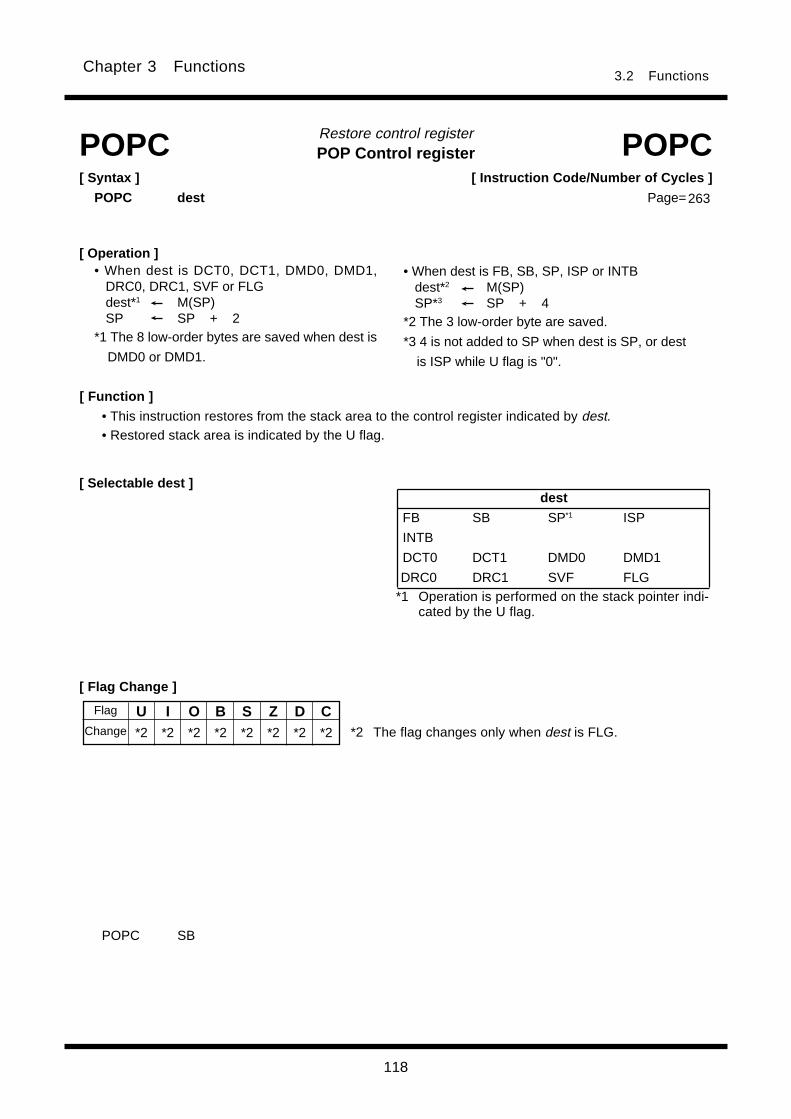
118
Chapter 3 Functions3.2 Functions
POP Control registerRestore control register
[ Flag Change ]
POPC POPC[ Syntax ]
POPC dest
[ Function ]
• This instruction restores from the stack area to the control register indicated by dest.• Restored stack area is indicated by the U flag.
POPC SB
[ Operation ]• When dest is DCT0, DCT1, DMD0, DMD1,
DRC0, DRC1, SVF or FLGdest*1 M(SP)SP SP + 2
*1 The 8 low-order bytes are saved when dest is
DMD0 or DMD1.
U I O B S Z D C*2 *2 *2 *2 *2 *2 *2 *2 *2 The flag changes only when dest is FLG.
[ Selectable dest ]
[ Instruction Code/Number of Cycles ]
Page=263
Flag
Change
dest
FB SB SP*1 ISP
INTB
DCT0 DCT1 DMD0 DMD1
DRC0 DRC1 SVF FLG*1 Operation is performed on the stack pointer indi-
cated by the U flag.
• When dest is FB, SB, SP, ISP or INTBdest*2 M(SP)SP*3 SP + 4
*2 The 3 low-order byte are saved.
*3 4 is not added to SP when dest is SP, or dest
is ISP while U flag is "0".

119
Chapter 3 Functions3.2 Functions
POP MultipleRestore multiple registers
[ Description Example ]
[ Selectable dest ]
[ Function ]
FB SB A1 A0 R3 R2 R1 R0
POPM POPM[ Syntax ]
POPM dest
• This instruction restores the registers selected by dest collectively from the stack area.• Registers are restored from the stack area in the following order:
dest *3
R0 R1 R2 R3 A0 A1 SB FB
*3 You can choose multiple dest.
[ Flag Change ]
POPM R0,R1,A0,SB,FB
U I O B S Z D C
Restored sequentially beginningwith R0
[ Instruction Code/Number of Cycles ]
Page= 264
Flag
Change
[ Operation ]dest*3 M(SP)SP SP + n1*1 2SP SP + n2*2 4*1 n1 denotes the number of R0, R1, R2 and R3 registers to be restored.*2 n2 denotes the number of A0, A1, SB and FB registers to be restored.*3 The 3 low-order bytes are saved when dest is A0, A1, SB and FB.

120
Chapter 3 Functions3.2 Functions
PUSHSave register/memory/immediate data
[ Flag Change ]
[ Description Example ]
[ Selectable src ]
PUSH PUSH[ Syntax ]
PUSH.size src
[ Function ]• This instruction saves src to the stack area.• When (.W) is specified for the size specifier (.size) and src is the address register, the 16 low-order bits
of the address register are the data to be operated on.
PUSH.B #5
PUSH.W #100H
PUSH.L R2R0
B , W , L
[ Operation ]
• When the size specifier (.size) is (.B) • When the size specifier (.size) is (.W) SP SP - 2 SP SP - 2 M(SP)*1 src/[src] M(SP) src/[src] *1 The 8 high-order bits become indeterminate.
Even when (.B) is specified for the size specifier (.size) , SP is decreased by 2.
• When the size specifier (.size) is (.L)SP SP - 4M(SP)*2 src/[src]*2 When src is address register(A0, A1), the 8 high-order bits become 0.
U I O B S Z D C
[ Instruction Code/Number of Cycles ]
Page= 265
Change
Flag
*3 Indirect addressing [src] can be used in all addressing except R0L/R0/R2R0, R0H/R2/-, R1L/R1/R3R1,R1H/R3/-, SP/SP/SP, dsp:8[SP], and #IMM.
src* 3
R0L/R0/R2R0 R0H/R2/-
R1L/R1/R3R1 R1H/R3/-
A0/A0/A0 A1/A1/A1 [A0] [A1]
dsp:8[A0] dsp:8[A1] dsp:8[SB] dsp:8[FB]
dsp:16[A0] dsp:16[A1] dsp:16[SB] dsp:16[FB]
dsp:24[A0] dsp:24[A1] abs24 abs16
#IMM8/#IMM16/#IMM32
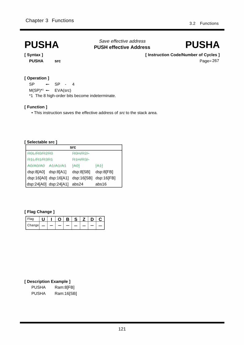
121
Chapter 3 Functions3.2 Functions
PUSH effective AddressSave effective address
[ Flag Change ]
[ Description Example ]
[ Function ]
[ Selectable src ]
PUSHA PUSHA[ Syntax ]
PUSHA src
• This instruction saves the effective address of src to the stack area.
PUSHA Ram:8[FB]
PUSHA Ram:16[SB]
[ Operation ]
SP SP - 4
M(SP)*1 EVA(src)*1 The 8 high-order bits become indeterminate.
U I O B S Z D CFlag
Change
[ Instruction Code/Number of Cycles ]
Page= 267
src
R0L/R0/R2R0 R0H/R2/-
R1L/R1/R3R1 R1H/R3/-
A0/A0/A0 A1/A1/A1 [A0] [A1]
dsp:8[A0] dsp:8[A1] dsp:8[SB] dsp:8[FB]
dsp:16[A0] dsp:16[A1] dsp:16[SB] dsp:16[FB]
dsp:24[A0] dsp:24[A1] abs24 abs16
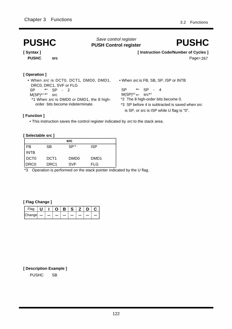
122
Chapter 3 Functions3.2 Functions
PUSH Control registerSave control register
[ Syntax ]
PUSHC src
[ Flag Change ]
[ Description Example ]
PUSHC SB
PUSHC PUSHC
[ Function ]• This instruction saves the control register indicated by src to the stack area.
[ Selectable src ]
*3 Operation is performed on the stack pointer indicated by the U flag.
U I O B S Z D C
267
[ Instruction Code/Number of Cycles ]
Page=
Flag
Change
• When src is FB, SB, SP, ISP or INTB
SP SP - 4 M(SP)*2 src*3
*2 The 8 high-order bits become 0.*3 SP before 4 is subtracted is saved when src
is SP, or src is ISP while U flag is "0".
src
FB SB SP*3 ISP
INTB
DCT0 DCT1 DMD0 DMD1
DRC0 DRC1 SVF FLG
[ Operation ]
• When src is DCT0, DCT1, DMD0, DMD1,DRC0, DRC1, SVF or FLG
SP SP - 2M(SP)*1 src*1 When src is DMD0 or DMD1, the 8 high-
order bits become indeterminate.

123
Chapter 3 Functions3.2 Functions
PUSH MultipleSave multiple registers
[ Syntax ]
PUSHM src
[ Description Example ]
[ Function ]
R0 R1 R2 R3 A0 A1 SB FB
PUSHM PUSHM
• This instruction saves the registers selected by src collectively to the stack area.• The registers are saved to the stack area in the following order:
src *4
R0 R1 R2 R3 A0 A1 SB FB*4 You can choose multiple src.
PUSHM R0,R1,A0,SB,FB
U I O B S Z D C
[ Instruction Code/Number of Cycles ]
Page= 268
Saved sequentially beginning with FB
[ Flag Change ]
Flag
Change
[ Selectable src ]
[ Operation ]SP SP – n1*1 2SP SP – n2*1 4M(SP)*3 src*1 n1 denotes the number of R0, R1, R2 and R3 registers to be saved.*2 n2 denotes the number of A0, A1, SB and FB registers to be saved.
*3 When src is A0, A1, SB or FB, the 8 high-order bits become 0.

124
Chapter 3 Functions3.2 Functions
REturn from InTerruptReturn from interrupt
[ Syntax ]
REIT
[ Flag Change ]
[ Description Example ]
[ Function ]
REIT REIT
REIT
U I O B S Z D C*1 *1 *1 *1 *1 *1 *1 *1
Flag*1 Becomes the value in the stack.
[ Instruction Code/Number of Cycles ]
Page= 269
Change
[ Operation ]
PCML M(SP)
SP SP + 2
PCH M(SP)*1
SP SP + 2
FLG M(SP)
SP SP + 2*1 The 8 high-order bits are saved.
• This instruction restores the PC and FLG that were saved when an interrupt request was accepted toreturn from the interrupt handler routine.

125
3.2 FunctionsChapter 3 Functions
Repeat MultiPle & AdditionCalculate sum-of-products
[ Description Example ]
RMPA RMPA[ Syntax ]
RMPA.size
B , W
[ Function ]
• This instruction performs sum-of-product calculations, with the multiplicand address indicated by A0, themultiplier address indicated by A1, and the count of operation indicated by R3. Calculations areperformed including the sign bits and the result is stored in R1R2R0 .
• The content of the address register when the instruction is completed indicates the next address of thelast-read data.
• When an interrupt request is received during instruction execution, the interrupt is acknowledged aftera sum-of- product addition is completed (i.e., after the content of R3 is decremented by 1).
• Make sure that R1R2R0 has the initial value set.
RMPA.B
[ Operation ] *1
Repeat
R1R2R0 R1R2R0 + M(A0) M(A1)
A0 A0 + 2 (1) *2
A1 A1 + 2 (1) *2
R3 R3 - 1
Until R3 = 0*1 When you set a value 0 in R3, this instruction is ingored.
*2 Shown in ( )*2 applies when (.B) is selected for the size specifier (.size).
Conditions
O : The flag is set when +231-1 or -231 is exceeded during operation; otherwise cleared.
U I O B S Z D CFlag
[ Instruction Code/Number of Cycles ]
Page=
[ Fl ag Change ]
Change
269
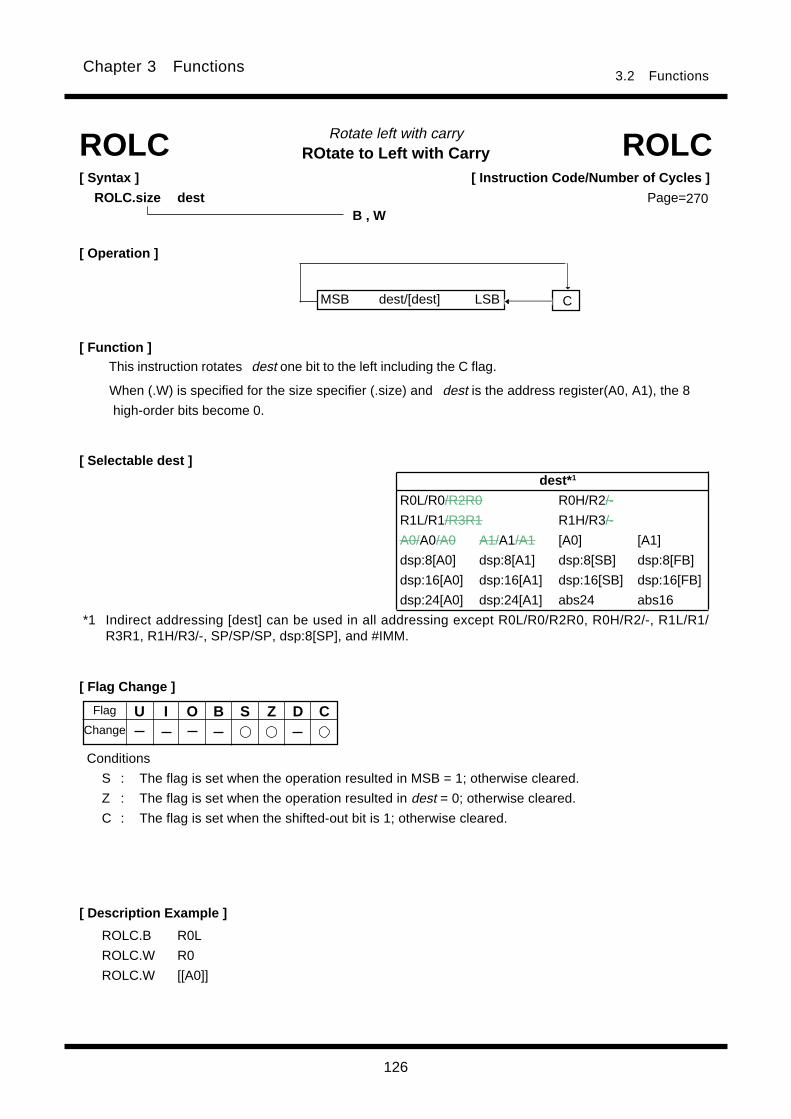
126
3.2 FunctionsChapter 3 Functions
ROtate to Left with CarryRotate left with carry
C
[ Description Example ]
[ Function ]
[ Selectable dest ]
ROLC ROLC
[ Flag Change ]
ROLC.B R0L
ROLC.W R0
ROLC.W [[A0]]
B , W
[ Syntax ]
ROLC.size dest
[ Operation ]
This instruction rotates dest one bit to the left including the C flag.
When (.W) is specified for the size specifier (.size) and dest is the address register(A0, A1), the 8
high-order bits become 0.
U I O B S Z D C
Conditions
S : The flag is set when the operation resulted in MSB = 1; otherwise cleared.
Z : The flag is set when the operation resulted in dest = 0; otherwise cleared.
C : The flag is set when the shifted-out bit is 1; otherwise cleared.
[ Instruction Code/Number of Cycles ]
Page=270
MSB dest/[dest] LSB
Flag
Change
*1 Indirect addressing [dest] can be used in all addressing except R0L/R0/R2R0, R0H/R2/-, R1L/R1/R3R1, R1H/R3/-, SP/SP/SP, dsp:8[SP], and #IMM.
dest* 1
R0L/R0/R2R0 R0H/R2/-
R1L/R1/R3R1 R1H/R3/-
A0/A0/A0 A1/A1/A1 [A0] [A1]
dsp:8[A0] dsp:8[A1] dsp:8[SB] dsp:8[FB]
dsp:16[A0] dsp:16[A1] dsp:16[SB] dsp:16[FB]
dsp:24[A0] dsp:24[A1] abs24 abs16
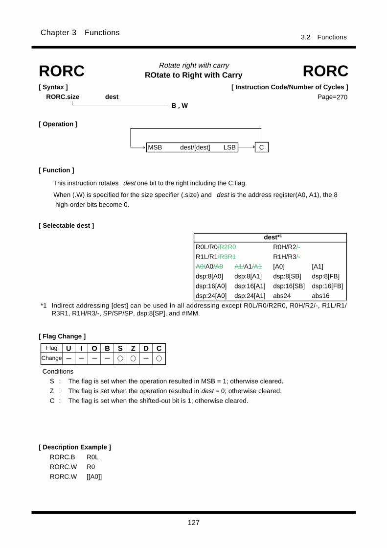
127
3.2 FunctionsChapter 3 Functions
ROtate to Right with CarryRotate right with carry
[ Syntax ]
RORC.size dest
[ Flag Change ]
[ Function ]
[ Selectable dest ]
RORC RORC
[ Description Example ]
RORC.B R0L
RORC.W R0
RORC.W [[A0]]
B , W
[ Operation ]
This instruction rotates dest one bit to the right including the C flag.
When (.W) is specified for the size specifier (.size) and dest is the address register(A0, A1), the 8
high-order bits become 0.
U I O B S Z D C
Conditions
S : The flag is set when the operation resulted in MSB = 1; otherwise cleared.
Z : The flag is set when the operation resulted in dest = 0; otherwise cleared.
C : The flag is set when the shifted-out bit is 1; otherwise cleared.
C
[ Instruction Code/Number of Cycles ]
Page=270
MSB dest/[dest] LSB
Flag
Change
*1 Indirect addressing [dest] can be used in all addressing except R0L/R0/R2R0, R0H/R2/-, R1L/R1/R3R1, R1H/R3/-, SP/SP/SP, dsp:8[SP], and #IMM.
dest* 1
R0L/R0/R2R0 R0H/R2/-
R1L/R1/R3R1 R1H/R3/-
A0/A0/A0 A1/A1/A1 [A0] [A1]
dsp:8[A0] dsp:8[A1] dsp:8[SB] dsp:8[FB]
dsp:16[A0] dsp:16[A1] dsp:16[SB] dsp:16[FB]
dsp:24[A0] dsp:24[A1] abs24 abs16
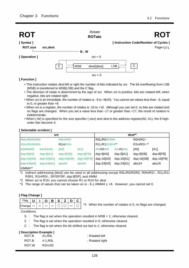
128
3.2 FunctionsChapter 3 Functions
ROTateRotateROT ROT
[ Syntax ]
ROT.size src,destB , W
• This instruction rotates dest left or right the number of bits indicated by src. The bit overflowing from LSB(MSB) is transferred to MSB(LSB) and the C flag.
• The direction of rotate is determined by the sign of src. When src is positive, bits are rotated left; whennegative, bits are rotated right.
• When src is an immediate, the number of rotates is - 8 to +8(≠0). You cannot set values less than - 8, equalto 0, or greater than +8.
• When src is a register, the number of rotates is -16 to +16. Although you can set 0, no bits are rotated andno flags are changed. When you set a value less than -17 or greater than +17, the result of rotation isindeterminate.
• When (.W) is specified for the size specifier (.size) and dest is the address register(A0, A1), the 8 high-order bits become 0.
[ Operation ]
LSB
src > 0
src < 0
C
[ Function ]
MSB
[ Description Example ]ROT.B #1,R0L ; Rotated left
ROT.B #-1,R0L ; Rotated right
ROT.W R1H,R2
[ Flag Change ]
U I O B S Z D C
*1 Indirect addressing [dest] can be used in all addressing except R0L/R0/R2R0, R0H/R2/-, R1L/R1/R3R1, R1H/R3/-, SP/SP/SP, dsp:8[SP], and #IMM.
*2 When src is R1H, you cannot choose R1 or R1H for dest.*3 The range of values that can be taken on is - 8 < #IMM4 < +8. However, you cannot set 0.
[ Selectable src/dest ]
C
[ Instruction Code/Number of Cycles ]
Page=271
dest/[dest]
Flag
Change
Conditions
S : The flag is set when the operation resulted in MSB = 1; otherwise cleared.
Z : The flag is set when the operation resulted in 0; otherwise cleared.
C : The flag is set when the bit shifted out last is 1; otherwise cleared.
*4 When the number of rotates is 0, no flags are changed.
src dest* 1
R0L/R0/R2R0 R0H/R2/-
R1L/R1/R3R1 R1H/R3/-
A0/A0/A0 A1/A1/A1 [A0] [A1]
dsp:8[A0] dsp:8[A1] dsp:8[SB] dsp:8[FB]
dsp:16[A0] dsp:16[A1] dsp:16[SB] dsp:16[FB]
dsp:24[A0] dsp:24[A1] abs24 abs16
#IMM4*3
R0L/R0/R2R0 R0H/R2/-
R1L/R1/R3R1*2 R1H/R3/-*2
A0/A0/A0 A1/A1/A1 [A0] [A1]
dsp:8[A0] dsp:8[A1] dsp:8[SB] dsp:8[FB]
dsp:16[A0] dsp:16[A1] dsp:16[SB] dsp:16[FB]
dsp:24[A0] dsp:24[A1] abs24 abs16

129
3.2 FunctionsChapter 3 Functions
ReTurn from SubroutineReturn from subroutine
[ Flag Change ]
[ Description Example ]RTS
RTS RTS[ Syntax ]
RTS
[ Operation ]
PCML M(SP)
SP SP + 2
PCH M(SP)*1
SP SP + 2
*1 The 8 low-order bits are saved.
[ Function ]
Flag
Change
U I O B S Z D C
• This instruction causes control to return from a subroutine.
[ Instruction Code/Number of Cycles ]
Page=272
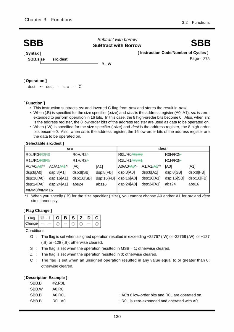
130
3.2 FunctionsChapter 3 Functions
SuBtract with BorrowSubtract with borrow
[ Syntax ]
SBB.size src,dest
[ Operation ]___
dest dest - src - C
[ Flag Change ]
[ Description Example ]SBB.B #2,R0L
SBB.W A0,R0
SBB.B A0,R0L ; A0's 8 low-order bits and R0L are operated on.
SBB.B R0L,A0 ; R0L is zero-expanded and operated with A0.
[ Function ]• This instruction subtracts src and inverted C flag from dest and stores the result in dest.• When (.B) is specified for the size specifier (.size) and dest is the address register (A0, A1), src is zero-
extended to perform operation in 16 bits. In this case, the 8 high-oreder bits become 0. Also, when srcis the address register, the 8 low-order bits of the address register are used as data to be operated on.
• When (.W) is specified for the size specifier (.size) and dest is the address register, the 8 high-orderbits become 0. Also, when src is the address register, the 16 low-order bits of the address register arethe data to be operated on.
[ Selectable src/dest ]
SBB SBB
B , W
*1 When you specify (.B) for the size specifier (.size), you cannot choose A0 and/or A1 for src and destsimultaneously.
Conditions
O : The flag is set when a signed operation resulted in exceeding +32767 (.W) or -32768 (.W), or +127
(.B) or -128 (.B); otherwise cleared.
S : The flag is set when the operation resulted in MSB = 1; otherwise cleared.
Z : The flag is set when the operation resulted in 0; otherwise cleared.
C : The flag is set when an unsigned operation resulted in any value equal to or greater than 0;
otherwise cleared.
U I O B S Z D C
[ Instruction Code/Number of Cycles ]
Page= 273
Flag
Change
src dest
R0L/R0/R2R0 R0H/R2/-
R1L/R1/R3R1 R1H/R3/-
A0/A0/A0*1 A1/A1/A1*1 [A0] [A1]
dsp:8[A0] dsp:8[A1] dsp:8[SB] dsp:8[FB]
dsp:16[A0] dsp:16[A1] dsp:16[SB] dsp:16[FB]
dsp:24[A0] dsp:24[A1] abs24 abs16
#IMM8/#IMM16
R0L/R0/R2R0 R0H/R2/-
R1L/R1/R3R1 R1H/R3/-
A0/A0/A0*1 A1/A1/A1*1 [A0] [A1]
dsp:8[A0] dsp:8[A1] dsp:8[SB] dsp:8[FB]
dsp:16[A0] dsp:16[A1] dsp:16[SB] dsp:16[FB]
dsp:24[A0] dsp:24[A1] abs24 abs16
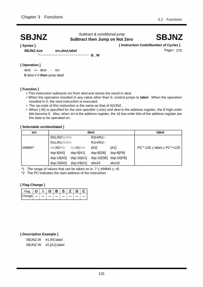
131
3.2 FunctionsChapter 3 Functions
SuBtract then Jump on Not ZeroSubtract & conditional jump
[ Selectable src/dest/label ]
[ Function ]
SBJNZ SBJNZ[ Syntax ]
SBJNZ.size src,dest,label
• This instruction subtracts src from dest and stores the result in dest.• When the operation resulted in any value other than 0, control jumps to label . When the operation
resulted in 0, the next instruction is executed.• The op-code of this instruction is the same as that of ADJNZ.• When (.W) is specified for the size specifier (.size) and dest is the address register, the 8 high-order
bits become 0. Also, when src is the address register, the 16 low-order bits of the address register arethe data to be operated on.
*1 The range of values that can be taken on is -7 < #IMM4 < +8.*2 The PC indicates the start address of the instruction.
[ Flag Change ]
[ Description Example ]
SBJNZ.W #1,R0,label
SBJNZ.W #2,[A1],label
B , W
[ Operation ]
dest dest - src
if dest ≠ 0 then jump label
Flag
Change
U I O B S Z D C
[ Instruction Code/Number of Cycles ]
Page= 275
src dest label
R0L/R0/R2R0 R0H/R2/-
R1L/R1/R3R1 R1H/R3/-
#IMM4*1 A0/A0/A0 A1/A1/A1 [A0] [A1] PC*2-126 < label < PC*2+129
dsp:8[A0] dsp:8[A1] dsp:8[SB] dsp:8[FB]
dsp:16[A0] dsp:16[A1] dsp:16[SB] dsp:16[FB]
dsp:24[A0] dsp:24[A1] abs24 abs16

132
3.2 FunctionsChapter 3 Functions
Cnd Condition Expression Cnd Condition Expression
GEU/C C=1 Equal to or greater than LTU/NC C=0 Smaller than
C flag is 1. C flag is 0.
EQ/Z Z=1 Equal to = NE/NZ Z=0 Not equal
Z flag is 1. Z flag is 0.
GTU____
C Z=1 Greater than LEU____
C Z=0 Equal to or smaller than
PZ S=0 Positive or zero 0 N S=1 Negative 0
GE S O=0 Equal to or greater than LE (S O) Z=1 Equal to or smaller than
(signed value) (signed value)
GT (S O) Z=0 Greater than (signed value) LT S O=1 Smaller than (signed value)
O O=1 O flag is 1. NO O=0 O flag is 0.
≠
Store Condition on ConditionStore on condition
[ Syntax ]
SCCnd label
[ Selectable dest ]
[ Description Example ]SCC R0L
SCC [dsp:8[A0]]
[ Function ]
[ Operation ]
if true then dest 1 if true then [dest] 1
else dest 0 else [dest] 0
SCCnd
[ Flag Change ]
U I O B S Z D C
SCCnd[ Instruction Code/Number of Cycles ]
Page=
• When the condition specified by Cnd is true, this instruction stores a 1 in dest ; when the condition isfalse, it stores a 0 in dest.
• When dest is the address register(A0, A1), the 8 high-order bits of the address register become 0.• There are following types of Cnd:
Flag
Change
A
A A
A
dest* 1
R0L/R0/R2R0 R0H/R2/-
R1L/R1/R3R1 R1H/R3/-
A0/A0/A0 A1/A1/A1 [A0] [A1]
dsp:8[A0] dsp:8[A1] dsp:8[SB] dsp:8[FB]
dsp:16[A0] dsp:16[A1] dsp:16[SB] dsp:16[FB]
dsp:24[A0] dsp:24[A1] abs24 abs16
*1 Indirect addressing [dest] can be used in all addressing except R0L/R0/R2R0, R0H/R2/-, R1L/R1/R3R1, R1H/R3/-, SP/SP/SP, dsp:8[SP], and #IMM.
276
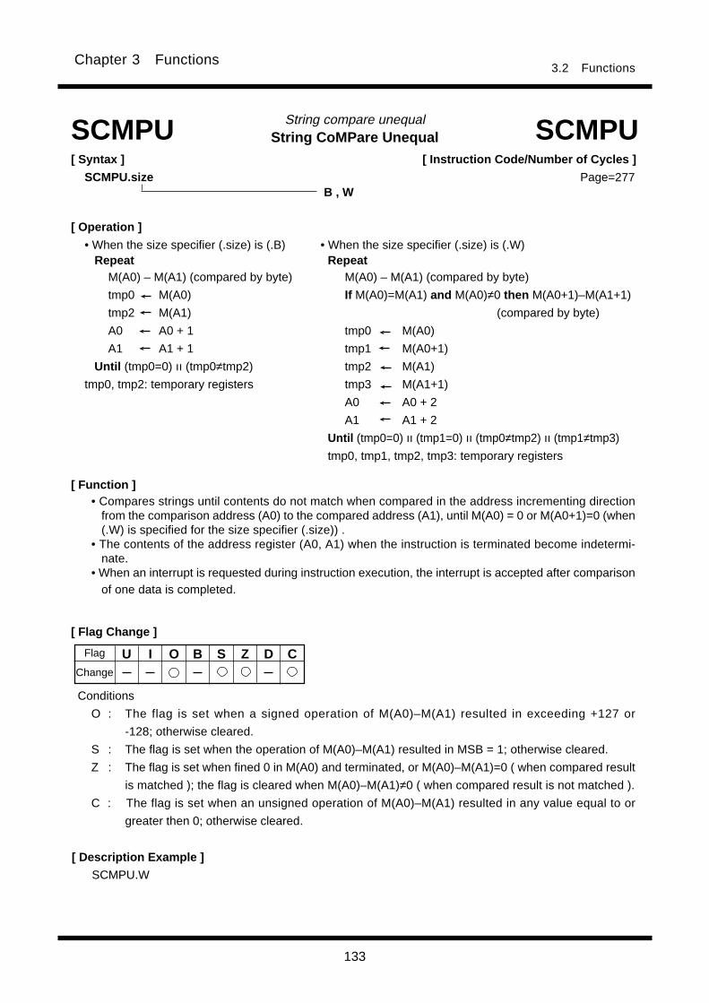
133
3.2 FunctionsChapter 3 Functions
[ Flag Change ]
[ Description Example ]
SCMPU.W
[ Operation ]
• When the size specifier (.size) is (.B) • When the size specifier (.size) is (.W) Repeat Repeat
M(A0) – M(A1) (compared by byte) M(A0) – M(A1) (compared by byte)
tmp0 M(A0) If M(A0)=M(A1) and M(A0)≠0 then M(A0+1)–M(A1+1)
tmp2 M(A1) (compared by byte)
A0 A0 + 1 tmp0 M(A0)
A1 A1 + 1 tmp1 M(A0+1)
Until (tmp0=0) ıı (tmp0≠tmp2) tmp2 M(A1)
tmp0, tmp2: temporary registers tmp3 M(A1+1)
A0 A0 + 2
A1 A1 + 2
Until (tmp0=0) ıı (tmp1=0) ıı (tmp0≠tmp2) ıı (tmp1≠tmp3)
tmp0, tmp1, tmp2, tmp3: temporary registers
U I O B S Z D CChange
Flag
String CoMPare UnequalString compare unequal
[ Syntax ]
SCMPU.size
SCMPU SCMPU[ Instruction Code/Number of Cycles ]
Page=B , W
Conditions
O : The flag is set when a signed operation of M(A0)–M(A1) resulted in exceeding +127 or
-128; otherwise cleared.
S : The flag is set when the operation of M(A0)–M(A1) resulted in MSB = 1; otherwise cleared.
Z : The flag is set when fined 0 in M(A0) and terminated, or M(A0)–M(A1)=0 ( when compared result
is matched ); the flag is cleared when M(A0)–M(A1)≠0 ( when compared result is not matched ).
C : The flag is set when an unsigned operation of M(A0)–M(A1) resulted in any value equal to or
greater then 0; otherwise cleared.
[ Function ]• Compares strings until contents do not match when compared in the address incrementing direction
from the comparison address (A0) to the compared address (A1), until M(A0) = 0 or M(A0+1)=0 (when(.W) is specified for the size specifier (.size)) .
• The contents of the address register (A0, A1) when the instruction is terminated become indetermi-nate.
• When an interrupt is requested during instruction execution, the interrupt is accepted after comparisonof one data is completed.
277

134
3.2 FunctionsChapter 3 Functions
SHift ArithmeticShift arithmetic
[ Syntax ]
SHA.size src,dest
SHA
B , W , L
[ Function ]
[ Operation ]
When src < 0
When src > 0
[ Selectable src/dest ]
*1 Indirect addressing [dest] can be used in all addressing except R0L/R0/R2R0, R0H/R2/-, R1L/R1/R3R1, R1H/R3/-, SP/SP/SP, dsp:8[SP], and #IMM.
*2 When src is R1H, you cannot choose R1, R1H or R3R1 for dest.*3 When (.B) or (.W) is selected for the size specifier (.size), the range of values that can be taken on is
-8 < #IMM4 < +8(≠0). When (.L) is selected for the size specifier (.size), the range of values that canbe taken on is -16 < #IMM8 < +16 (≠0).
SHA[ Instruction Code/Number of Cycles ]
Page= 278
0
CMSB dest/[dest] LSB
MSB dest/[dest] LSBC
src dest* 1
R0L/R0/R2R0 R0H/R2/-
R1L/R1/R3R1 R1H*2/R3/-
A0/A0/A0 A1/A1/A1 [A0] [A1]
dsp:8[A0] dsp:8[A1] dsp:8[SB] dsp:8[FB]
dsp:16[A0] dsp:16[A1] dsp:16[SB] dsp:16[FB]
dsp:24[A0] dsp:24[A1] abs24 abs16
#IMM4/#IMM8*3
R0L/R0/R2R0 R0H/R2/-
R1L/R1/R3R1*2 R1H/R3/-*2
A0/A0/A0 A1/A1/A1 [A0] [A1]
dsp:8[A0] dsp:8[A1] dsp:8[SB] dsp:8[FB]
dsp:16[A0] dsp:16[A1] dsp:16[SB] dsp:16[FB]
dsp:24[A0] dsp:24[A1] abs24 abs16
• This instruction arithmetically shifts dest left or right the number of bits indicated by src. The bit over-
flowing from LSB(MSB)is transferred to the C flg.
• The direction of shift is determined by the sign of src. When src is positive, bits are shifted left; when
negative, bits are shifted right.
• When src is an immediate and you selected (.B) or (.W) for the size specifier (.size), the number of
shifts is -8 to +8(≠0). You cannot set values less than -8, equal to 0, or greater than +8. When you
selected (.L) for the size specifier (.size), the number of shifts is -16 to +16(≠0). You cannot set values
less than -16, equal to 0, or greater than +16.
• When src is a register, the number of shifts is -16 to +16. Although you can set 0, no bits are shifted
and no flags are changed. When you set a value less than -16 or greater than +16, the result of shift
is indeterminate.
• When (.L) is specified for the size specifier (.size) and dest is the address register, dest is zero-
extended to perform operation in 32 bits. The 24 low-order bits of the operation result are stored in
dest.

135
3.2 FunctionsChapter 3 Functions
[ Description Example ]SHA.B #3,R0L ; Arithmetically shifted left
SHA.B #-3,R0L ; Arithmetically shifted right
SHA.L R1H,Ram:8[A1]
SHA.W R1H,[[A1]]
[ Flag Change ]* 1
U I O B S Z D CFlag
Change
Conditions
O*2 : The flag is cleared when all the shift resulted in MSB and shift out bit are the same value;
otherwise set.
S*2 : The flag is set when the operation resulted in MSB = 1; otherwise cleared.
Z*2 : The flag is set when the operation resulted in 0; otherwise cleared.
C*2 : The flag is set when the bit at last shifted out is 1; otherwise cleared.
*2 When (.L) is specified for the sign specifier (.size) and dest is the address register(A0, A1), the flag
become indeterminate.
*1 When the number of shifts is 0, no flags are changed.
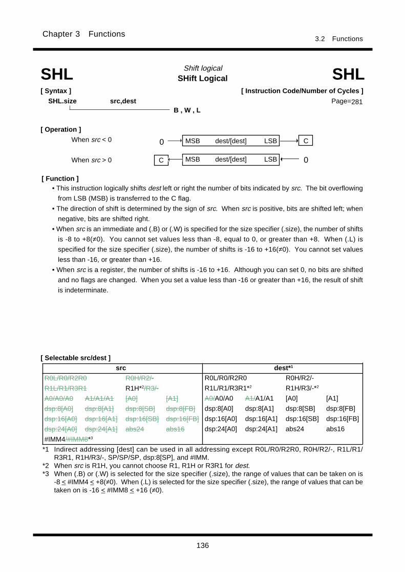
136
3.2 FunctionsChapter 3 Functions
SHift LogicalShift logical
[ Syntax ]
SHL.size src,dest
SHL SHL
B , W , L
0
0
[ Operation ]
When src < 0
When src > 0
[ Function ]
[ Instruction Code/Number of Cycles ]
Page=281
MSB dest/[dest] LSB
MSB dest/[dest] LSB
C
C
[ Selectable src/dest ]
*1 Indirect addressing [dest] can be used in all addressing except R0L/R0/R2R0, R0H/R2/-, R1L/R1/R3R1, R1H/R3/-, SP/SP/SP, dsp:8[SP], and #IMM.
*2 When src is R1H, you cannot choose R1, R1H or R3R1 for dest.*3 When (.B) or (.W) is selected for the size specifier (.size), the range of values that can be taken on is
-8 < #IMM4 < +8(≠0). When (.L) is selected for the size specifier (.size), the range of values that can betaken on is -16 < #IMM8 < +16 (≠0).
• This instruction logically shifts dest left or right the number of bits indicated by src. The bit overflowing
from LSB (MSB) is transferred to the C flag.
• The direction of shift is determined by the sign of src. When src is positive, bits are shifted left; when
negative, bits are shifted right.
• When src is an immediate and (.B) or (.W) is specified for the size specifier (.size), the number of shifts
is -8 to +8(≠0). You cannot set values less than -8, equal to 0, or greater than +8. When (.L) is
specified for the size specifier (.size), the number of shifts is -16 to +16(≠0). You cannot set values
less than -16, or greater than +16.
• When src is a register, the number of shifts is -16 to +16. Although you can set 0, no bits are shifted
and no flags are changed. When you set a value less than -16 or greater than +16, the result of shift
is indeterminate.
src dest* 1
R0L/R0/R2R0 R0H/R2/-
R1L/R1/R3R1 R1H*2/R3/-
A0/A0/A0 A1/A1/A1 [A0] [A1]
dsp:8[A0] dsp:8[A1] dsp:8[SB] dsp:8[FB]
dsp:16[A0] dsp:16[A1] dsp:16[SB] dsp:16[FB]
dsp:24[A0] dsp:24[A1] abs24 abs16
#IMM4/#IMM8*3
R0L/R0/R2R0 R0H/R2/-
R1L/R1/R3R1*2 R1H/R3/-*2
A0/A0/A0 A1/A1/A1 [A0] [A1]
dsp:8[A0] dsp:8[A1] dsp:8[SB] dsp:8[FB]
dsp:16[A0] dsp:16[A1] dsp:16[SB] dsp:16[FB]
dsp:24[A0] dsp:24[A1] abs24 abs16
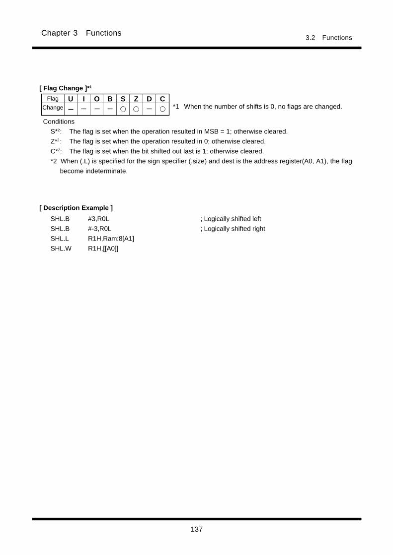
137
3.2 FunctionsChapter 3 Functions
[ Description Example ]
SHL.B #3,R0L ; Logically shifted left
SHL.B #-3,R0L ; Logically shifted right
SHL.L R1H,Ram:8[A1]
SHL.W R1H,[[A0]]
[ Flag Change ]* 1
U I O B S Z D C
Conditions
S*2: The flag is set when the operation resulted in MSB = 1; otherwise cleared.
Z*2: The flag is set when the operation resulted in 0; otherwise cleared.
C*2: The flag is set when the bit shifted out last is 1; otherwise cleared.
*2 When (.L) is specified for the sign specifier (.size) and dest is the address register(A0, A1), the flag
become indeterminate.
Flag
Change *1 When the number of shifts is 0, no flags are changed.

138
3.2 FunctionsChapter 3 Functions
String INput String input
[ Syntax ]
SIN.size
[ Description Example ]
SIN.W
SIN SIN
B , W
[ Operation ] *1
• When size specifier (.size) is (.B) • When size specifier (.size) is (.W)
While R3≠0 Do While R3≠0 Do
M(A1) M(A0) M(A1) M(A0)
A1 A1 + 1 A1 A1 + 2
R3 R3 - 1 R3 R3 - 1
End End
Flag
Change
U I O B S Z D C
[ Instruction Code/Number of Cycles ]
Page=
[ Flag Change ]
[ Function ]
• Transfers strings from the fixed source address indicated by A0 to the destination address indicated by
A1 in the address incrementing direction as many times as specified by R3.
• Set the source of transfer address in A0, the destination address in A1, and the transfer count in R3.
• The content of A1 when the instruction is terminated indicates the next address following the last data
transferred.
• When an interrupt is requested during instruction execution, the interrupt is accepted after comparison
of one data is completed.
*1 When you set a value 0 in R3, this instruction is ingored.
283
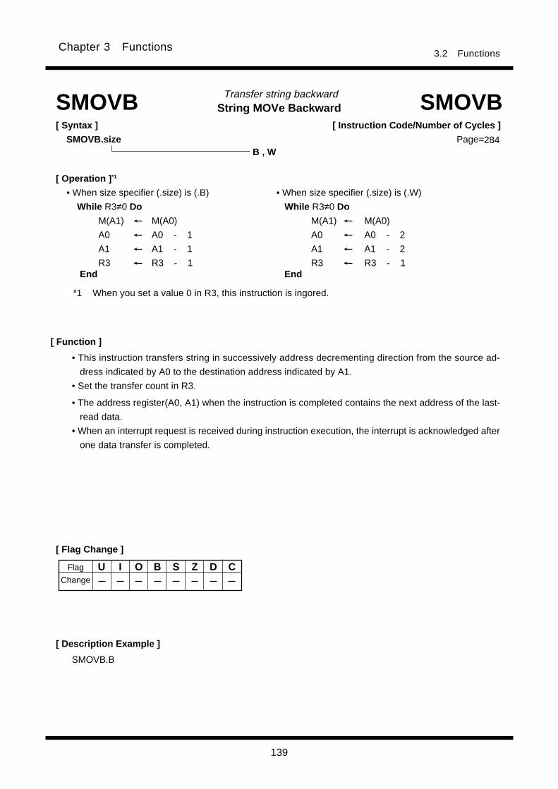
139
3.2 FunctionsChapter 3 Functions
String MOVe Backward Transfer string backward
[ Syntax ]
SMOVB.size
[ Description Example ]
SMOVB.B
SMOVB SMOVB
B , W
[ Operation ] *1
• When size specifier (.size) is (.B) • When size specifier (.size) is (.W)
While R3≠0 Do While R3≠0 Do
M(A1) M(A0) M(A1) M(A0)
A0 A0 - 1 A0 A0 - 2
A1 A1 - 1 A1 A1 - 2
R3 R3 - 1 R3 R3 - 1
Flag
Change
U I O B S Z D C
284
[ Instruction Code/Number of Cycles ]
Page=
[ Flag Change ]
[ Function ]
• This instruction transfers string in successively address decrementing direction from the source ad-
dress indicated by A0 to the destination address indicated by A1.
• Set the transfer count in R3.
• The address register(A0, A1) when the instruction is completed contains the next address of the last-
read data.
• When an interrupt request is received during instruction execution, the interrupt is acknowledged after
one data transfer is completed.
*1 When you set a value 0 in R3, this instruction is ingored.
End End
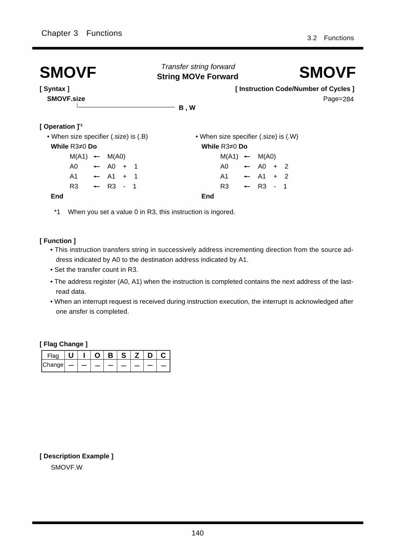
140
3.2 FunctionsChapter 3 Functions
String MOVe ForwardTransfer string forward
[ Syntax ]
SMOVF.size
[ Description Example ]
SMOVF SMOVF
[ Flag Change ]
SMOVF.W
B , W
Flag
Change
U I O B S Z D C
[ Operation ] *1
• When size specifier (.size) is (.B) • When size specifier (.size) is (.W)
While R3≠0 Do While R3≠0 Do
M(A1) M(A0) M(A1) M(A0)
A0 A0 + 1 A0 A0 + 2
A1 A1 + 1 A1 A1 + 2
R3 R3 - 1 R3 R3 - 1
End End
[ Instruction Code/Number of Cycles ]
Page=284
[ Function ]• This instruction transfers string in successively address incrementing direction from the source ad-
dress indicated by A0 to the destination address indicated by A1.
• Set the transfer count in R3.
• The address register (A0, A1) when the instruction is completed contains the next address of the last-
read data.
• When an interrupt request is received during instruction execution, the interrupt is acknowledged after
one ansfer is completed.
*1 When you set a value 0 in R3, this instruction is ingored.
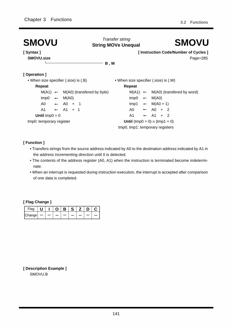
141
3.2 FunctionsChapter 3 Functions
String MOVe UnequalTransfer string
[ Syntax ]
SMOVU.size
SMOVU SMOVU
B , W
[ Instruction Code/Number of Cycles ]
Page=
[ Flag Change ]
[ Description Example ]
[ Function ]
• Transfers strings from the source address indicated by A0 to the destination address indicated by A1 in
the address incrementing direction until 0 is detected.
• The contents of the address register (A0, A1) when the instruction is terminated become indetermi-
nate.
• When an interrupt is requested during instruction execution, the interrupt is accepted after comparison
of one data is completed.
SMOVU.B
[ Operation ]
• When size specifier (.size) is (.B) • When size specifier (.size) is (.W)
Repeat Repeat
M(A1) M(A0) (transfered by byte) M(A1) M(A0) (transfered by word)
tmp0 M(A0) tmp0 M(A0)
A0 A0 + 1 tmp1 M(A0 + 1)
A1 A1 + 1 A0 A0 + 2
Until tmp0 = 0 A1 A1 + 2
tmp0: temporary register Until (tmp0 = 0) ıı (tmp1 = 0)
tmp0, tmp1: temporary registers
U I O B S Z D CChange
Flag
285
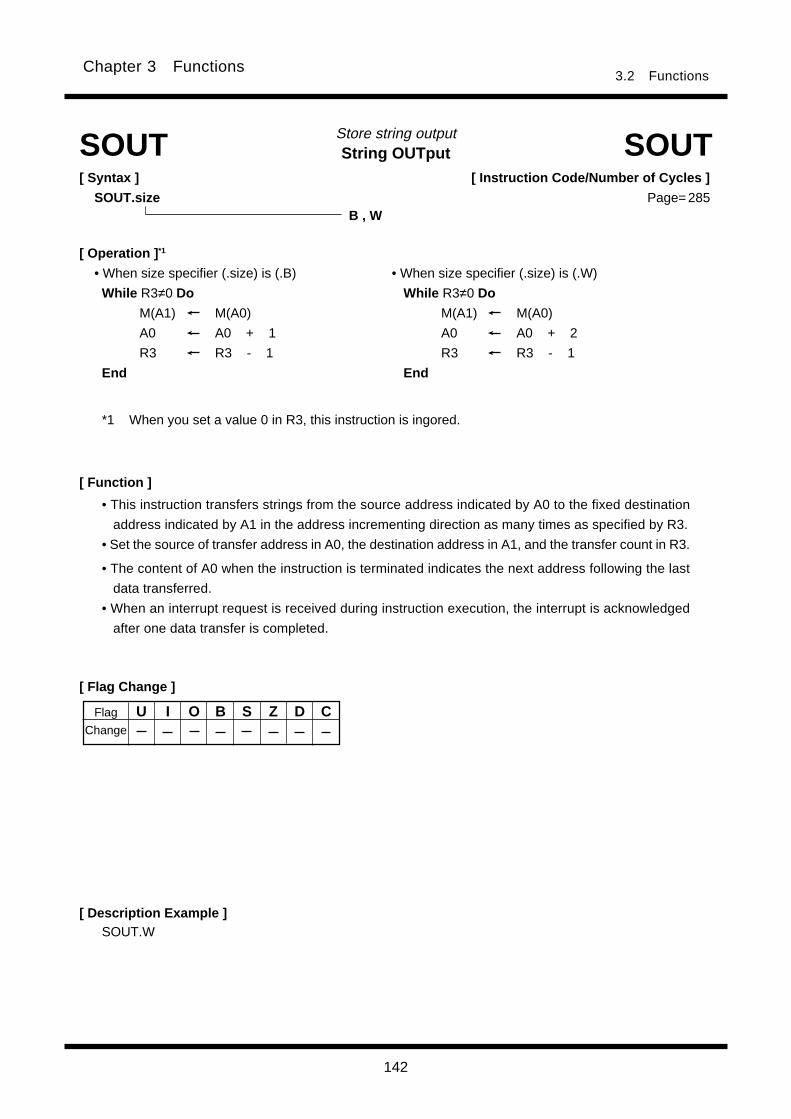
142
Chapter 3 Functions3.2 Functions
String OUTputStore string output
[ Function ]
[ Flag Change ]
[ Description Example ]SOUT.W
SOUT SOUT[ Syntax ]
SOUT.size
• This instruction transfers strings from the source address indicated by A0 to the fixed destination
address indicated by A1 in the address incrementing direction as many times as specified by R3.
• Set the source of transfer address in A0, the destination address in A1, and the transfer count in R3.
• The content of A0 when the instruction is terminated indicates the next address following the last
data transferred.
• When an interrupt request is received during instruction execution, the interrupt is acknowledged
after one data transfer is completed.
B , W
[ Operation ] *1
• When size specifier (.size) is (.B) • When size specifier (.size) is (.W)
While R3≠0 Do While R3≠0 Do
M(A1) M(A0) M(A1) M(A0)
A0 A0 + 1 A0 A0 + 2
R3 R3 - 1 R3 R3 - 1
End End
Flag
Change
U I O B S Z D C
[ Instruction Code/Number of Cycles ]
Page=
*1 When you set a value 0 in R3, this instruction is ingored.
285

143
Chapter 3 Functions3.2 Functions
String SToReStore string
[ Function ]
[ Flag Change ]
[ Description Example ]SSTR.B
SSTR SSTR[ Syntax ]
SSTR.size
• This instruction stores string, with the store data indicated by R0L/R0, the transfer address indi-
cated by A1, and the transfer count indicated by R3.
• The content of A1 when the instruction is terminated indicates the next address following the last
data transferred.
• When an interrupt request is received during instruction execution, the interrupt is acknowledged
after one data transfer is completed.
B , W
[ Operation ] *1
• When size specifier (.size) is (.B) • When size specifier (.size) is (.W)
While R3≠0 Do While R3≠0 Do
M(A1) R0L M(A1) R0
A1 A1 + 1 A1 A1 + 2
R3 R3 - 1 R3 R3 - 1
End End
Flag
Change
U I O B S Z D C
[ Instruction Code/Number of Cycles ]
Page=
*1 When you set a value 0 in R3, this instruction is ingored.
286
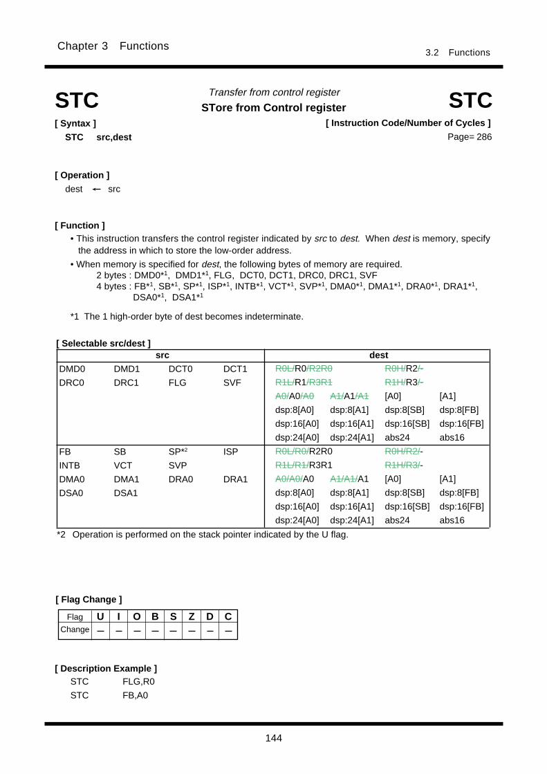
144
Chapter 3 Functions3.2 Functions
Transfer from control register
STore from Control register[ Syntax ]
STC src,dest
[ Description Example ]
[ Function ]
[ Selectable src/dest ]
STC STC
• This instruction transfers the control register indicated by src to dest. When dest is memory, specifythe address in which to store the low-order address.
• When memory is specified for dest, the following bytes of memory are required.2 bytes : DMD0*1, DMD1*1, FLG, DCT0, DCT1, DRC0, DRC1, SVF4 bytes : FB*1, SB*1, SP*1, ISP*1, INTB*1, VCT*1, SVP*1, DMA0*1, DMA1*1, DRA0*1, DRA1*1,
DSA0*1, DSA1*1
STC FLG,R0
STC FB,A0
[ Operation ]
dest src
[ Flag Change ]
*2 Operation is performed on the stack pointer indicated by the U flag.
Flag
Change
U I O B S Z D C
[ Instruction Code/Number of Cycles ]
Page=
src dest
DMD0 DMD1 DCT0 DCT1
DRC0 DRC1 FLG SVF
FB SB SP*2 ISP
INTB VCT SVP
DMA0 DMA1 DRA0 DRA1
DSA0 DSA1
R0L/R0/R2R0 R0H/R2/-
R1L/R1/R3R1 R1H/R3/-
A0/A0/A0 A1/A1/A1 [A0] [A1]
dsp:8[A0] dsp:8[A1] dsp:8[SB] dsp:8[FB]
dsp:16[A0] dsp:16[A1] dsp:16[SB] dsp:16[FB]
dsp:24[A0] dsp:24[A1] abs24 abs16
R0L/R0/R2R0 R0H/R2/-
R1L/R1/R3R1 R1H/R3/-
A0/A0/A0 A1/A1/A1 [A0] [A1]
dsp:8[A0] dsp:8[A1] dsp:8[SB] dsp:8[FB]
dsp:16[A0] dsp:16[A1] dsp:16[SB] dsp:16[FB]
dsp:24[A0] dsp:24[A1] abs24 abs16
*1 The 1 high-order byte of dest becomes indeterminate.
286
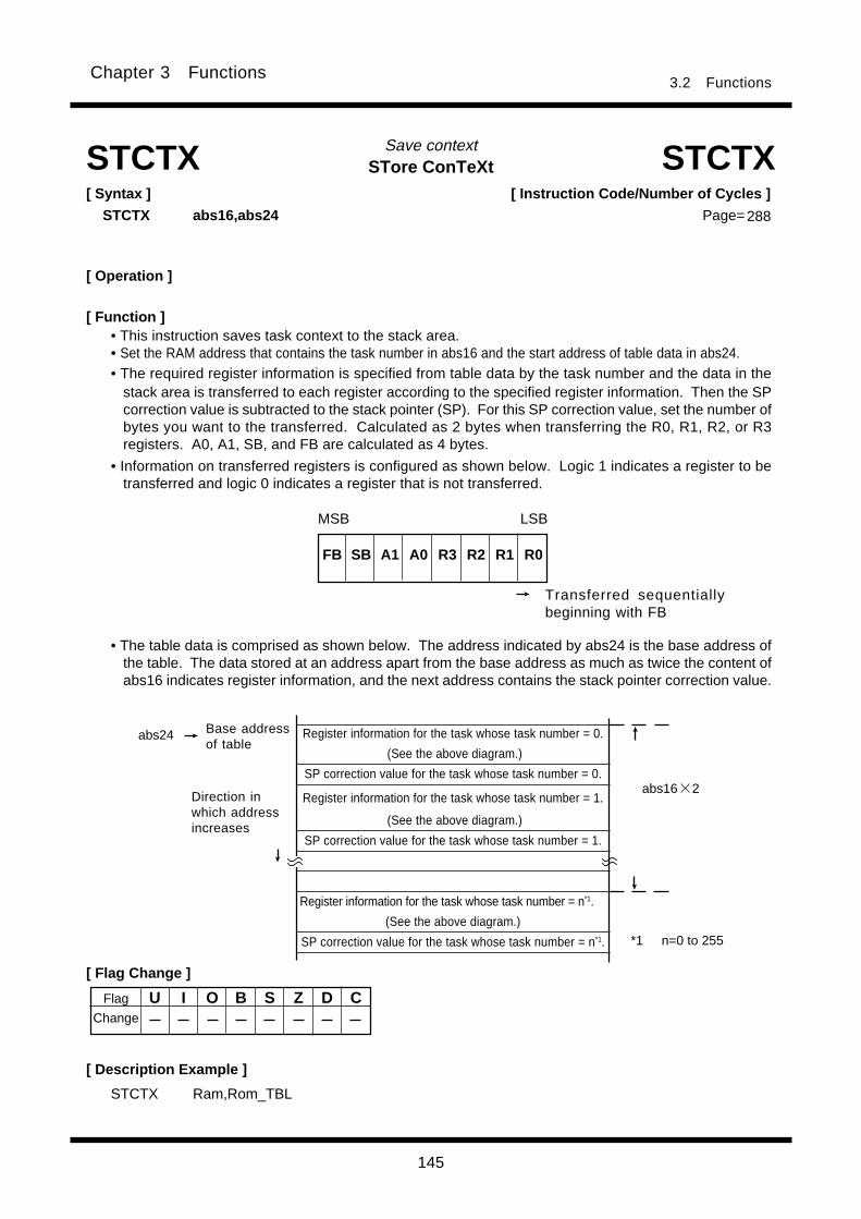
145
Chapter 3 Functions3.2 Functions
STore ConTeXtSave context
STCTX Ram,Rom_TBL
[ Flag Change ]
STCTX STCTX[ Syntax ]
STCTX abs16,abs24
[ Description Example ]
[ Operation ]
U I O B S Z D C
[ Instruction Code/Number of Cycles ]
Page=
Flag
Change
[ Function ]• This instruction saves task context to the stack area.• Set the RAM address that contains the task number in abs16 and the start address of table data in abs24.• The required register information is specified from table data by the task number and the data in the
stack area is transferred to each register according to the specified register information. Then the SPcorrection value is subtracted to the stack pointer (SP). For this SP correction value, set the number ofbytes you want to the transferred. Calculated as 2 bytes when transferring the R0, R1, R2, or R3registers. A0, A1, SB, and FB are calculated as 4 bytes.
• Information on transferred registers is configured as shown below. Logic 1 indicates a register to betransferred and logic 0 indicates a register that is not transferred.
Transferred sequentiallybeginning with FB
FB SB A1 A0 R3 R2 R1 R0
MSB LSB
• The table data is comprised as shown below. The address indicated by abs24 is the base address ofthe table. The data stored at an address apart from the base address as much as twice the content ofabs16 indicates register information, and the next address contains the stack pointer correction value.
Register information for the task whose task number = 0.
(See the above diagram.)
SP correction value for the task whose task number = 0.
Register information for the task whose task number = 1.
(See the above diagram.)
SP correction value for the task whose task number = 1.
Register information for the task whose task number = n*1.
(See the above diagram.)
SP correction value for the task whose task number = n*1.
abs24 Base addressof table
Direction inwhich addressincreases
abs16 2
*1 n=0 to 255
288
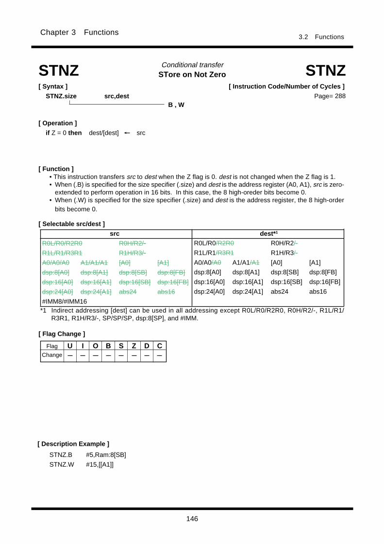
146
Chapter 3 Functions3.2 Functions
STore on Not ZeroConditional transfer
[ Function ]
[ Flag Change ]
[ Description Example ]
[ Selectable src/dest ]
STNZ STNZ[ Syntax ]
STNZ.size src,dest
• This instruction transfers src to dest when the Z flag is 0. dest is not changed when the Z flag is 1.• When (.B) is specified for the size specifier (.size) and dest is the address register (A0, A1), src is zero-
extended to perform operation in 16 bits. In this case, the 8 high-oreder bits become 0.• When (.W) is specified for the size specifier (.size) and dest is the address register, the 8 high-order
bits become 0.
STNZ.B #5,Ram:8[SB]
STNZ.W #15,[[A1]]
[ Operation ]
if Z = 0 then dest/[dest] src
Flag
Change
U I O B S Z D C
[ Instruction Code/Number of Cycles ]
Page=B , W
*1 Indirect addressing [dest] can be used in all addressing except R0L/R0/R2R0, R0H/R2/-, R1L/R1/R3R1, R1H/R3/-, SP/SP/SP, dsp:8[SP], and #IMM.
src dest* 1
R0L/R0/R2R0 R0H/R2/-
R1L/R1/R3R1 R1H/R3/-
A0/A0/A0 A1/A1/A1 [A0] [A1]
dsp:8[A0] dsp:8[A1] dsp:8[SB] dsp:8[FB]
dsp:16[A0] dsp:16[A1] dsp:16[SB] dsp:16[FB]
dsp:24[A0] dsp:24[A1] abs24 abs16
#IMM8/#IMM16
R0L/R0/R2R0 R0H/R2/-
R1L/R1/R3R1 R1H/R3/-
A0/A0/A0 A1/A1/A1 [A0] [A1]
dsp:8[A0] dsp:8[A1] dsp:8[SB] dsp:8[FB]
dsp:16[A0] dsp:16[A1] dsp:16[SB] dsp:16[FB]
dsp:24[A0] dsp:24[A1] abs24 abs16
288
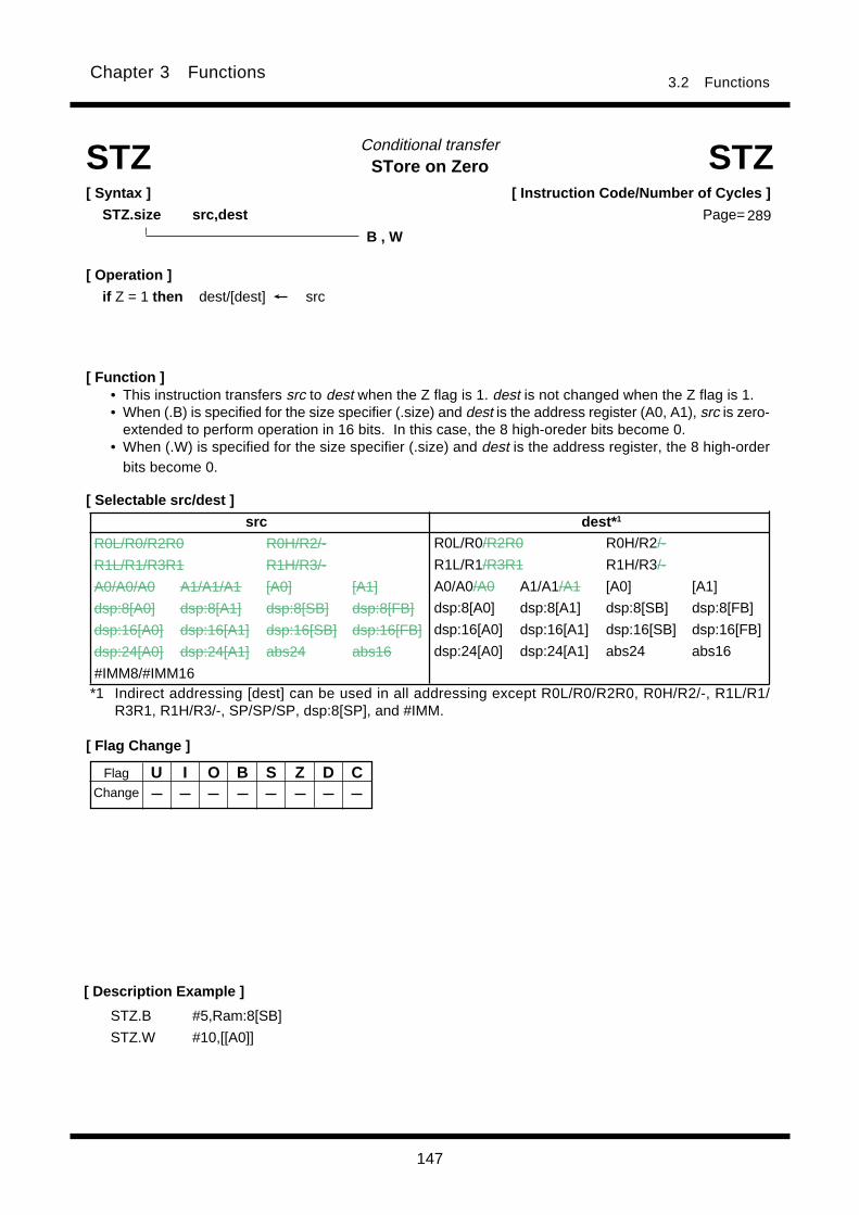
147
Chapter 3 Functions3.2 Functions
STore on ZeroConditional transfer
[ Syntax ]
STZ.size src,dest
[ Function ]
[ Flag Change ]
• This instruction transfers src to dest when the Z flag is 1. dest is not changed when the Z flag is 1.• When (.B) is specified for the size specifier (.size) and dest is the address register (A0, A1), src is zero-
extended to perform operation in 16 bits. In this case, the 8 high-oreder bits become 0.• When (.W) is specified for the size specifier (.size) and dest is the address register, the 8 high-order
bits become 0.
[ Description Example ]
[ Selectable src/dest ]
STZSTZ
STZ.B #5,Ram:8[SB]
STZ.W #10,[[A0]]
[ Operation ]
if Z = 1 then dest/[dest] src
Flag
Change
U I O B S Z D C
[ Instruction Code/Number of Cycles ]
Page=
B , W
*1 Indirect addressing [dest] can be used in all addressing except R0L/R0/R2R0, R0H/R2/-, R1L/R1/R3R1, R1H/R3/-, SP/SP/SP, dsp:8[SP], and #IMM.
src dest* 1
R0L/R0/R2R0 R0H/R2/-
R1L/R1/R3R1 R1H/R3/-
A0/A0/A0 A1/A1/A1 [A0] [A1]
dsp:8[A0] dsp:8[A1] dsp:8[SB] dsp:8[FB]
dsp:16[A0] dsp:16[A1] dsp:16[SB] dsp:16[FB]
dsp:24[A0] dsp:24[A1] abs24 abs16
#IMM8/#IMM16
R0L/R0/R2R0 R0H/R2/-
R1L/R1/R3R1 R1H/R3/-
A0/A0/A0 A1/A1/A1 [A0] [A1]
dsp:8[A0] dsp:8[A1] dsp:8[SB] dsp:8[FB]
dsp:16[A0] dsp:16[A1] dsp:16[SB] dsp:16[FB]
dsp:24[A0] dsp:24[A1] abs24 abs16
289

148
Chapter 3 Functions3.2 Functions
[ Instruction Code/Number of Cycles ]
Page=
STore on Zero eXtentionConditional transfer
[ Syntax ]
STZX.size src1,src2,dest
[ Flag Change ]
[ Description Example ]
STZX.B #1,#2,Ram:8[SB]
STZX.W #5,#10,[R0]
STZX STZX
[ Selectable src/dest ]
[ Operation ]
If Z = 1 then dest src1 If Z = 1 then [dest] src1
else dest src2 else [dest] src2
[ Function ]• This instruction transfers src1 to dest when the Z flag is 1. When the Z flag is 0, it transfers src2 to
dest.• When (.B) is specified for the size specifier (.size) and dest is the address register (A0, A1), src is zero-
extended to perform operation in 16 bits. In this case, the 8 high-oreder bits become 0.• When (.W) is specified for the size specifier (.size) and dest is the address register, the 8 high-order
bits become 0.
Flag
Change
U I O B S Z D C
src dest* 1
R0L/R0/R2R0 R0H/R2/-
R1L/R1/R3R1 R1H/R3/-
A0/A0/A0 A1/A1/A1 [A0] [A1]
dsp:8[A0] dsp:8[A1] dsp:8[SB] dsp:8[FB]
dsp:16[A0] dsp:16[A1] dsp:16[SB] dsp:16[FB]
dsp:24[A0] dsp:24[A1] abs24 abs16
#IMM8/#IMM16
R0L/R0/R2R0 R0H/R2/-
R1L/R1/R3R1 R1H/R3/-
A0/A0/A0 A1/A1/A1 [A0] [A1]
dsp:8[A0] dsp:8[A1] dsp:8[SB] dsp:8[FB]
dsp:16[A0] dsp:16[A1] dsp:16[SB] dsp:16[FB]
dsp:24[A0] dsp:24[A1] abs24 abs16
*1 Indirect addressing [dest] can be used in all addressing except R0L/R0/R2R0, R0H/R2/-, R1L/R1/R3R1, R1H/R3/-, SP/SP/SP, dsp:8[SP], and #IMM.
B , W289

149
Chapter 3 Functions3.2 Functions
[ Selectable src/dest ]* 1
SUBtractSubtract without borrow
[ Syntax ]
SUB.size (:format) src,dest
[ Operation ]
dest dest - src [dest] [dest] - src
dest dest - [src] [dest] [dest] - [src]
[ Function ]
SUB SUB
• This instruction subtracts src from dest and stores the result in dest.• When (.B) is specified for the size specifier (.size) and dest is the address register (A0, A1), src is zero-
extended to perform operation in 16 bits. In this case, the 8 high-oreder bits become 0. Also, when srcis the address register, the 8 low-order bits of the address register are used as data to be operated on.
• When (.W) is specified for the size specifier (.size) and dest is the address register, the 8 high-orderbits become 0. Also, when src is the address register, the 16 low-order bits of the address register arethe data to be operated on.
• When (.L) is specified for the size specifier (.size) and dest is the address register, dest is zero-extended to perform operation in 32 bits. The 24 low-order bits of the operation result are stored indest. When src is the address register, src is zero-extended to perform operation in 32 bits. The flagsalso change states depending on the result of 32-bit operation.
[ Flag Change ]
G , S (Can be specified)
B , W , L
Flag
Change
U I O B S Z D C
(See the next page for src/dest classified by format.)
Conditions
O : The flag is set when a signed operation resulted in exceeding +2147483647(.L) or
-2147483648(.L), +32767 (.W) or -32768 (.W), or +127 (.B) or -128 (.B); otherwise cleared.
S : The flag is set when the operation resulted in MSB = 1; otherwise cleared.
Z : The flag is set when the operation resulted in 0; otherwise cleared.
C : The flag is set when an unsigned operation resulted in any value equal to or greater than 0;
otherwise cleared.
[ Instruction Code/Number of Cycles ]
Page=
*1 Indirect addressing [src] and [dest] can be used in all addressing except R0L/R0/R2R0, R0H/R2/-, R1L/R1/R3R1,R1H/R3/-, SP/SP/SP, dsp:8[SP], and #IMM.
*2 When you specify (.B) for the size specifier (.size), you cannot choose A0 and/or A1 for src and destsimultaneously.
src dest
R0L/R0/R2R0 R0H/R2/-
R1L/R1/R3R1 R1H/R3/-
A0/A0/A0*2 A1/A1/A1*2 [A0] [A1]
dsp:8[A0] dsp:8[A1] dsp:8[SB] dsp:8[FB]
dsp:16[A0] dsp:16[A1] dsp:16[SB] dsp:16[FB]
dsp:24[A0] dsp:24[A1] abs24 abs16
#IMM8/#IMM16/#IMM32
R0L/R0/R2R0 R0H/R2/-
R1L/R1/R3R1 R1H/R3/-
A0/A0/A0*2 A1/A1/A1*2 [A0] [A1]
dsp:8[A0] dsp:8[A1] dsp:8[SB] dsp:8[FB]
dsp:16[A0] dsp:16[A1] dsp:16[SB] dsp:16[FB]
dsp:24[A0] dsp:24[A1] abs24 abs16
290

150
Chapter 3 Functions3.2 Functions
[src/dest Classified by Format]
G format* 1
S format
[ Description Example ]SUB.B A0,R0L ; A0's 8 low-order bits and R0L are operated on.
SUB.B R0L,A0 ; R0L is zero-expanded and operated with A0.
SUB.B Ram:8[SB],R0L
SUB.W #2,[A0]
src dest *3
R0L/R0 dsp:8[SB] dsp:8[FB] abs16 R0L/R0 dsp:8[SB] dsp:8[FB] abs16
#IMM8/#IMM16*4
src dest
R0L/R0/R2R0 R0H/R2/-
R1L/R1/R3R1 R1H/R3/-
A0/A0/A0*2 A1/A1/A1*2 [A0] [A1]
dsp:8[A0] dsp:8[A1] dsp:8[SB] dsp:8[FB]
dsp:16[A0] dsp:16[A1] dsp:16[SB] dsp:16[FB]
dsp:24[A0] dsp:24[A1] abs24 abs16
#IMM8/#IMM16/#IMM32
R0L/R0/R2R0 R0H/R2/-
R1L/R1/R3R1 R1H/R3/-
A0/A0/A0*2 A1/A1/A1*2 [A0] [A1]
dsp:8[A0] dsp:8[A1] dsp:8[SB] dsp:8[FB]
dsp:16[A0] dsp:16[A1] dsp:16[SB] dsp:16[FB]
dsp:24[A0] dsp:24[A1] abs24 abs16
*1 Indirect addressing [src] and [dest] can be used in all addressing except R0L/R0/R2R0, R0H/R2/-, R1L/R1/R3R1,R1H/R3/-, SP/SP/SP, dsp:8[SP], and #IMM.
*2 When you specify (.B) for the size specifier (.size), you cannot choose A0 and/or A1 for src and destsimultaneously.
*3 Indirect addressing [dest] can be used in all addressing except R0L/R0/R2R0, R0H/R2/-, R1L/R1/R3R1,R1H/R3/-, SP/SP/SP, dsp:8[SP], and #IMM.
*4 You can specify only (.B) or (.W) for the size specifier (.size).

151
Chapter 3 Functions3.2 Functions
[ Selectable src/dest ]* 1
SUBtract eXtendSubtract extend without borrow
[ Syntax ]
SUBX src,dest
[ Operation ]
dest dest - EXT(src) [dest] [dest] - EXT(src)
dest dest - EXT([src]) [dest] [dest] - EXT([src])
[ Function ]
SUBX SUBX
• This instruction subtracts 8-bit src from dest (32 bits) after sign-extending src to 32 bits and stores theresult in dest.
• When dest is the address register (A0, A1), dest is zero-extended to perform operation in 32 bits. The24 low-order bits of the operation result are stored in dest. The flags also change states depending onthe result of 32-bit operation.
[ Flag Change ]
Flag
Change
U I O B S Z D C
Conditions
O : The flag is set when a signed operation resulted in exceeding +2147483647(.L) or
-2147483648(.L); otherwise cleared.
S : The flag is set when the operation resulted in MSB = 1; otherwise cleared.
Z : The flag is set when the operation resulted in 0; otherwise cleared.
C : The flag is set when an unsigned operation resulted in any value equal to or greater than 0;
otherwise cleared.
[ Instruction Code/Number of Cycles ]
Page=
*1 Indirect addressing [src] and [dest] can be used in all addressing except R0L/R0/R2R0, R0H/R2/-, R1L/R1/R3R1,R1H/R3/-, SP/SP/SP, dsp:8[SP], and #IMM.
src dest
R0L/R0/R2R0 R0H/R2/-
R1L/R1/R3R1 R1H/R3/-
A0/A0/A0 A1/A1/A1 [A0] [A1]
dsp:8[A0] dsp:8[A1] dsp:8[SB] dsp:8[FB]
dsp:16[A0] dsp:16[A1] dsp:16[SB] dsp:16[FB]
dsp:24[A0] dsp:24[A1] abs24 abs16
#IMM8
R0L/R0/R2R0 R0H/R2/-
R1L/R1/R3R1 R1H/R3/-
A0/A0/A0 A1/A1/A1 [A0] [A1]
dsp:8[A0] dsp:8[A1] dsp:8[SB] dsp:8[FB]
dsp:16[A0] dsp:16[A1] dsp:16[SB] dsp:16[FB]
dsp:24[A0] dsp:24[A1] abs24 abs16
[ Description Example ]SUBX R0L,A0
SUBX Ram:8[SB],R2R0
SUBX #2,[A0]
294
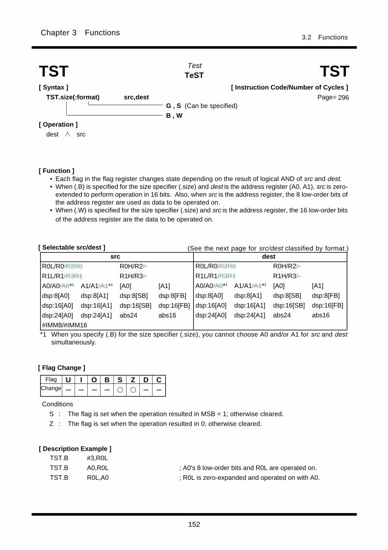
152
Chapter 3 Functions3.2 Functions
TeSTTest
[ Syntax ]
TST.size(:format) src,dest
[ Description Example ]TST.B #3,R0L
TST.B A0,R0L ; A0's 8 low-order bits and R0L are operated on.
TST.B R0L,A0 ; R0L is zero-expanded and operated on with A0.
[ Function ]
TST TST
• Each flag in the flag register changes state depending on the result of logical AND of src and dest.• When (.B) is specified for the size specifier (.size) and dest is the address register (A0, A1), src is zero-
extended to perform operation in 16 bits. Also, when src is the address register, the 8 low-order bits ofthe address register are used as data to be operated on.
• When (.W) is specified for the size specifier (.size) and src is the address register, the 16 low-order bitsof the address register are the data to be operated on.
[ Operation ]
dest src
[ Flag Change ]
[ Selectable src/dest ]
U I O B S Z D C
Conditions
S : The flag is set when the operation resulted in MSB = 1; otherwise cleared.
Z : The flag is set when the operation resulted in 0; otherwise cleared.
*1 When you specify (.B) for the size specifier (.size), you cannot choose A0 and/or A1 for src and destsimultaneously.
[ Instruction Code/Number of Cycles ]
Page=
Flag
Change
G , S (Can be specified)
B , W
src dest
R0L/R0/R2R0 R0H/R2/-
R1L/R1/R3R1 R1H/R3/-
A0/A0/A0*1 A1/A1/A1*1 [A0] [A1]
dsp:8[A0] dsp:8[A1] dsp:8[SB] dsp:8[FB]
dsp:16[A0] dsp:16[A1] dsp:16[SB] dsp:16[FB]
dsp:24[A0] dsp:24[A1] abs24 abs16
#IMM8/#IMM16
R0L/R0/R2R0 R0H/R2/-
R1L/R1/R3R1 R1H/R3/-
A0/A0/A0*1 A1/A1/A1*1 [A0] [A1]
dsp:8[A0] dsp:8[A1] dsp:8[SB] dsp:8[FB]
dsp:16[A0] dsp:16[A1] dsp:16[SB] dsp:16[FB]
dsp:24[A0] dsp:24[A1] abs24 abs16
(See the next page for src/dest classified by format.)
296
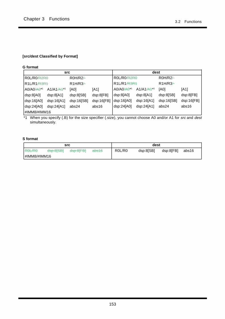
153
Chapter 3 Functions3.2 Functions
[src/dest Classified by Format]
G format
S format
*1 When you specify (.B) for the size specifier (.size), you cannot choose A0 and/or A1 for src and destsimultaneously.
src dest
R0L/R0 dsp:8[SB] dsp:8[FB] abs16 R0L/R0 dsp:8[SB] dsp:8[FB] abs16
#IMM8/#IMM16
src dest
R0L/R0/R2R0 R0H/R2/-
R1L/R1/R3R1 R1H/R3/-
A0/A0/A0*1 A1/A1/A1*1 [A0] [A1]
dsp:8[A0] dsp:8[A1] dsp:8[SB] dsp:8[FB]
dsp:16[A0] dsp:16[A1] dsp:16[SB] dsp:16[FB]
dsp:24[A0] dsp:24[A1] abs24 abs16
#IMM8/#IMM16
R0L/R0/R2R0 R0H/R2/-
R1L/R1/R3R1 R1H/R3/-
A0/A0/A0*1 A1/A1/A1*1 [A0] [A1]
dsp:8[A0] dsp:8[A1] dsp:8[SB] dsp:8[FB]
dsp:16[A0] dsp:16[A1] dsp:16[SB] dsp:16[FB]
dsp:24[A0] dsp:24[A1] abs24 abs16
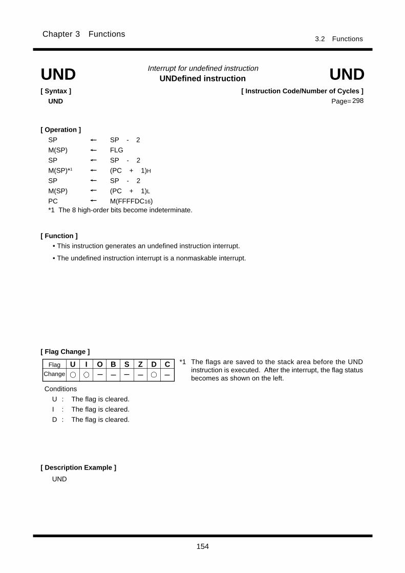
154
Chapter 3 Functions3.2 Functions
UNDefined instructionInterrupt for undefined instruction
[ Syntax ]
UND
[ Flag Change ]
[ Description Example ]
UND UND
[ Operation ]
SP SP - 2
M(SP) FLG
SP SP - 2
M(SP)*1 (PC + 1)H
SP SP - 2
M(SP) (PC + 1)L
PC M(FFFFDC16)*1 The 8 high-order bits become indeterminate.
*1 The flags are saved to the stack area before the UNDinstruction is executed. After the interrupt, the flag statusbecomes as shown on the left.
U I O B S Z D C
Conditions
U : The flag is cleared.
I : The flag is cleared.
D : The flag is cleared.
UND
[ Instruction Code/Number of Cycles ]
Page=
Flag
Change
• This instruction generates an undefined instruction interrupt.
• The undefined instruction interrupt is a nonmaskable interrupt.
[ Function ]
298
155
Chapter 3 Functions3.2 Functions
WAITWait
[ Syntax ]
WAIT
[ Flag Change ]
[ Description Example ]
[ Function ]
WAIT WAIT
• Stops program execution. Program execution is restarted when an interrupt whose priority is higher
than that of the stop/wait restoring interrupt priority setup bit is accepted or a reset is generated.
U I O B S Z D C
WAIT
[ Operation ]
[ Instruction Code/Number of Cycles ]
Page=
Flag
Change
298

156
Chapter 3 Functions3.2 Functions
eXCHanGeExchange
[ Flag Change ]
[ Description Example ]
[ Function ]
[ Selectable src/dest ]
XCHG XCHG[ Syntax ]
XCHG.size src,dest
• This instruction exchanges contents between src and dest.
• When (.B) is specified for the size specifier (.size) and dest is address register(A0, A1), 24 bits of zero-
expanded src data are placed in the address register and the 8 low-order bits of the address register
are placed in src.
• When (.W) is specified for the size specifier (.size) and dest is address register, 24 bits of zero- ex-
panded src data are placed in the address register and the 16 low-order bits of the address register are
placed in src. When src is address register, 24 bits data are placed in the address register and the 16
low-order bits of the address register are placed in dest.
B , W
[ Operation ]
dest/[dest] src
U I O B S Z D C
[ Instruction Code/Number of Cycles ]
Page=
Flag
Change
XCHG.B R0L,A0 ; A0's 8 low-order bits and R0L's zero-expanded value are exchanged.
XCHG.W R0,A1
XCHG.B R0L,[A0]
*1 Indirect addressing [dest] can be used in all addressing except R0L/R0/R2R0, R0H/R2/-, R1L/R1/R3R1, R1H/R3/-, SP/SP/SP, dsp:8[SP], and #IMM.
src dest* 1
R0L/R0/R2R0 R0H/R2/-
R1L/R1/R3R1 R1H/R3/-
A0/A0/A0 A1/A1/A1 [A0] [A1]
dsp:8[A0] dsp:8[A1] dsp:8[SB] dsp:8[FB]
dsp:16[A0] dsp:16[A1] dsp:16[SB] dsp:16[FB]
dsp:24[A0] dsp:24[A1] abs24 abs16
#IMM
R0L/R0/R2R0 R0H/R2/-
R1L/R1/R3R1 R1H/R3/-
A0/A0/A0 A1/A1/A1 [A0] [A1]
dsp:8[A0] dsp:8[A1] dsp:8[SB] dsp:8[FB]
dsp:16[A0] dsp:16[A1] dsp:16[SB] dsp:16[FB]
dsp:24[A0] dsp:24[A1] abs24 abs16
299

157
Chapter 3 Functions3.2 Functions
eXclusive ORExclusive OR
[ Syntax ]
XOR.size src,dest
[ Flag Change ]
[ Selectable src/dest ]* 1
[ Description Example ]
[ Function ]
XOR XOR
XOR.B A0,R0L ; A0's 8 low-order bits and R0L are exclusive ORed.
XOR.B R0L,A0 ; R0L is zero-expanded and exclusive ORed with A0.
XOR.B #3,R0L
XOR.W A0,A1
XOR.W [A0],[[A1]]
B , W
[ Operation ]
dest dest src [dest] [dest] src
dest dest [src] [dest] [dest] [src]
Flag
Change
U I O B S Z D C
Conditions
S : The flag is set when the operation resulted in MSB = 1; otherwise cleared.
Z : The flag is set when the operation resulted in 0; otherwise cleared.
*1 Indirect addressing [src] and [dest] can be used in all addressing except R0L/R0/R2R0, R0H/R2/-, R1L/R1/R3R1,R1H/R3/-, SP/SP/SP, dsp:8[SP], and #IMM.
*2 When you specify (.B) for the size specifier (.size), you cannot choose A0 and/or A1 for src and destsimultaneously.
• This instruction exclusive ORs src and dest together and stores the result in dest.• When (.B) is specified for the size specifier (.size) and dest is the address register (A0, A1), src is zero-
extended to perform operation in 16 bits. In this case, the 8 high-oreder bits become 0. Also, when srcis the address register, the 8 low-order bits of the address register are used as data to be operated on.
• When (.W) is specified for the size specifier (.size) and dest is the address register, the 8 high-orderbits become 0. Also, when src is the address register, the 16 low-order bits of the address register arethe data to be operated on.
[ Instruction Code/Number of Cycles ]
Page=
A
src dest
R0L/R0/R2R0 R0H/R2/-
R1L/R1/R3R1 R1H/R3/-
A0/A0/A0*2 A1/A1/A1*2 [A0] [A1]
dsp:8[A0] dsp:8[A1] dsp:8[SB] dsp:8[FB]
dsp:16[A0] dsp:16[A1] dsp:16[SB] dsp:16[FB]
dsp:24[A0] dsp:24[A1] abs24 abs16
#IMM8/#IMM16
R0L/R0/R2R0 R0H/R2/-
R1L/R1/R3R1 R1H/R3/-
A0/A0/A0*2 A1/A1/A1*2 [A0] [A1]
dsp:8[A0] dsp:8[A1] dsp:8[SB] dsp:8[FB]
dsp:16[A0] dsp:16[A1] dsp:16[SB] dsp:16[FB]
dsp:24[A0] dsp:24[A1] abs24 abs16
A A
A
299
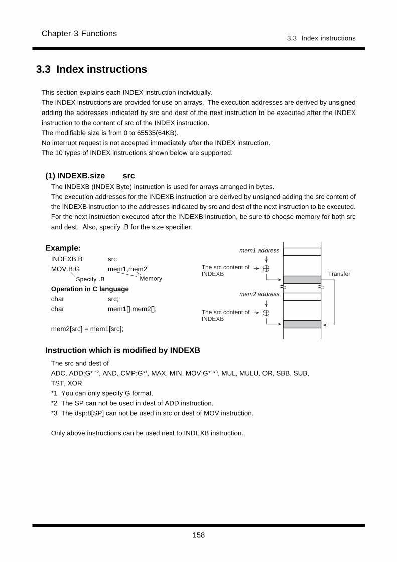
158
Chapter 3 Functions3.3 Index instructions
Specify .B Memory
3.3 Index instructions
This section explains each INDEX instruction individually.
The INDEX instructions are provided for use on arrays. The execution addresses are derived by unsigned
adding the addresses indicated by src and dest of the next instruction to be executed after the INDEX
instruction to the content of src of the INDEX instruction.
The modifiable size is from 0 to 65535(64KB).
No interrupt request is not accepted immediately after the INDEX instruction.
The 10 types of INDEX instructions shown below are supported.
(1) INDEXB.size srcThe INDEXB (INDEX Byte) instruction is used for arrays arranged in bytes.
The execution addresses for the INDEXB instruction are derived by unsigned adding the src content of
the INDEXB instruction to the addresses indicated by src and dest of the next instruction to be executed.
For the next instruction executed after the INDEXB instruction, be sure to choose memory for both src
and dest. Also, specify .B for the size specifier.
Example:INDEXB.B src
MOV.B:G mem1,mem2
Operation in C language
char src;
char mem1[],mem2[];
mem2[src] = mem1[src];
Instruction which is modified by INDEXB
The src and dest of
ADC, ADD:G*1*2, AND, CMP:G*1, MAX, MIN, MOV:G*1*3, MUL, MULU, OR, SBB, SUB,
TST, XOR.
*1 You can only specify G format.
*2 The SP can not be used in dest of ADD instruction.
*3 The dsp:8[SP] can not be used in src or dest of MOV instruction.
Only above instructions can be used next to INDEXB instruction.
AAAA
AAAA
mem1 address
mem2 address
The src content of INDEXB Transfer
The src content of INDEXB

159
Chapter 3 Functions3.3 Index instructions
Specify .B Memory
(2) INDEXBD.size srcThe INDEXBD (INDEX Byte Dest) instruction is used for arrays arranged in bytes.
The execution addresses for the INDEXBD instruction are derived by unsigned adding the src content of
the INDEXBD instruction to the addresses indicated by dest(some instructions are src) of the next in-
struction to be executed.
For the next instruction executed after the INDEXBD instruction, be sure to choose memory for
dest(some instructions are src ). Also, specify .B for the size specifier.
Example:
INDEXBD.B src
MOV.B:G mem1,mem2
Operation in C language
char src,mem1;
char mem2[];
mem2[src] = mem1;
Instruction which is modified by INDEXBD
The dest of
ABS, ADC, ADCF, ADD:G*1*2, AND, CLIP, CMP:G*1, DEC, INC, MAX, MIN, MOV:G*1*3,
MUL, MULU, NEG, NOT, OR, POP, ROLC, RORC, ROT, SBB, SHA, SHL, STNZ, STZ,
STZX, SUB, TST, XCHG, XOR.
The src of
DIV, DIVU, DIVX, PUSH
*1 You can only specify G format.
*2 The SP can not be used in dest of ADD instruction.
*3 The dsp:8[SP] can not be used in src or dest of MOV instruction.
Only above instructions can be used next to INDEXBD instruction.
AAAAAAAAAAAA
mem1 address
mem2 address
The src content of INDEXBD
Transfer
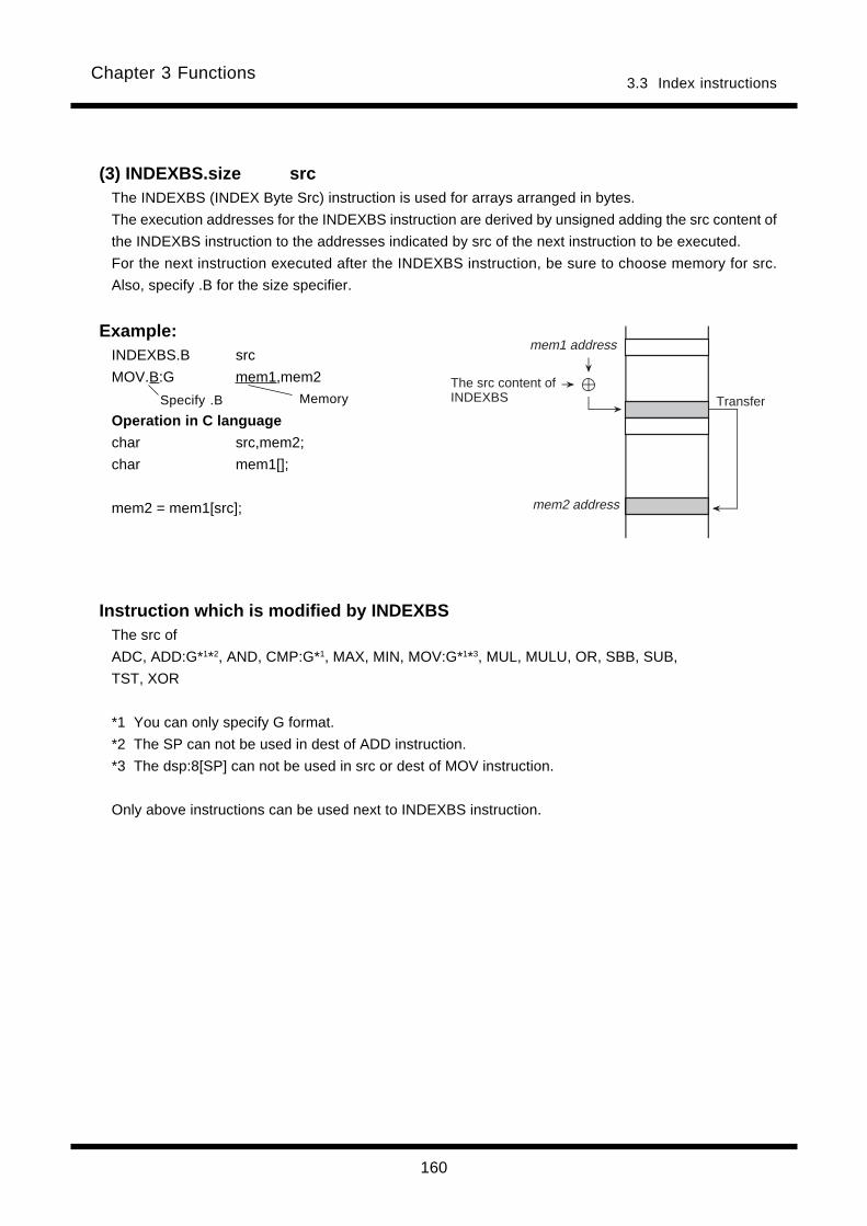
160
Chapter 3 Functions3.3 Index instructions
Specify .B Memory
(3) INDEXBS.size srcThe INDEXBS (INDEX Byte Src) instruction is used for arrays arranged in bytes.
The execution addresses for the INDEXBS instruction are derived by unsigned adding the src content of
the INDEXBS instruction to the addresses indicated by src of the next instruction to be executed.
For the next instruction executed after the INDEXBS instruction, be sure to choose memory for src.
Also, specify .B for the size specifier.
Example:INDEXBS.B src
MOV.B:G mem1,mem2
Operation in C language
char src,mem2;
char mem1[];
mem2 = mem1[src];
Instruction which is modified by INDEXBSThe src of
ADC, ADD:G*1*2, AND, CMP:G*1, MAX, MIN, MOV:G*1*3, MUL, MULU, OR, SBB, SUB,
TST, XOR
*1 You can only specify G format.
*2 The SP can not be used in dest of ADD instruction.
*3 The dsp:8[SP] can not be used in src or dest of MOV instruction.
Only above instructions can be used next to INDEXBS instruction.
AAAA
AAAAAAAA
mem1 address
The src content of INDEXBS
mem2 address
Transfer
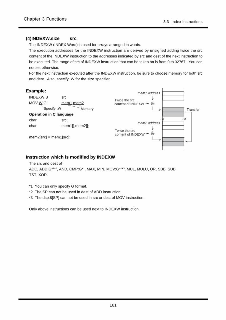
161
Chapter 3 Functions3.3 Index instructions
(4)INDEXW.size srcThe INDEXW (INDEX Word) is used for arrays arranged in words.
The execution addresses for the INDEXW instruction are derived by unsigned adding twice the src
content of the INDEXW instruction to the addresses indicated by src and dest of the next instruction to
be executed. The range of src of INDEXW instruction that can be taken on is from 0 to 32767. You can
not set otherwise.
For the next instruction executed after the INDEXW instruction, be sure to choose memory for both src
and dest. Also, specify .W for the size specifier.
Example:INDEXW.B src
MOV.W:G mem1,mem2
Operation in C language
char src;
char mem1[],mem2[];
mem2[src] = mem1[src];
Instruction which is modified by INDEXWThe src and dest of
ADC, ADD:G*1*2, AND, CMP:G*1, MAX, MIN, MOV:G*1*3, MUL, MULU, OR, SBB, SUB,
TST, XOR.
*1 You can only specify G format.
*2 The SP can not be used in dest of ADD instruction.
*3 The dsp:8[SP] can not be used in src or dest of MOV instruction.
Only above instructions can be used next to INDEXW instruction.
MemorySpecify .W
AAAAmem1 address
mem2 address
AAAAAAAA
AAAAAAAAAAAA
Twice the src content of INDEXW
Transfer
Twice the src content of INDEXW
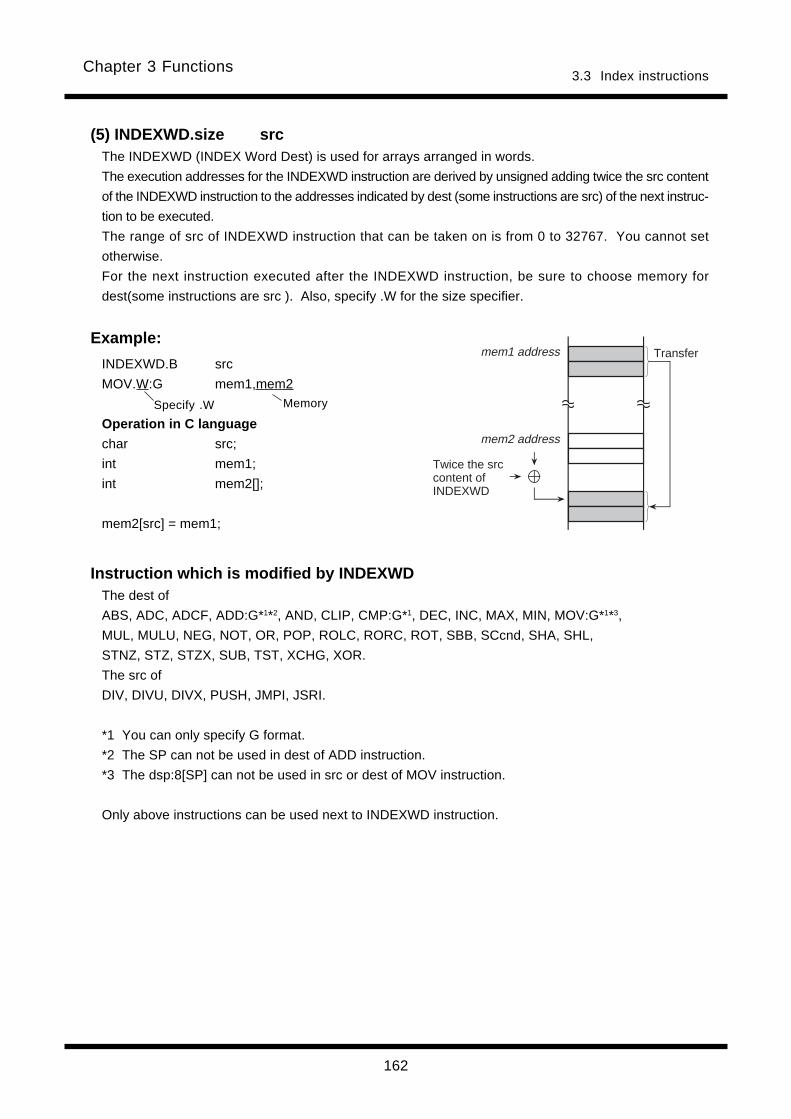
162
Chapter 3 Functions3.3 Index instructions
(5) INDEXWD.size srcThe INDEXWD (INDEX Word Dest) is used for arrays arranged in words.
The execution addresses for the INDEXWD instruction are derived by unsigned adding twice the src content
of the INDEXWD instruction to the addresses indicated by dest (some instructions are src) of the next instruc-
tion to be executed.
The range of src of INDEXWD instruction that can be taken on is from 0 to 32767. You cannot set
otherwise.
For the next instruction executed after the INDEXWD instruction, be sure to choose memory for
dest(some instructions are src ). Also, specify .W for the size specifier.
Example:
INDEXWD.B src
MOV.W:G mem1,mem2
Operation in C language
char src;
int mem1;
int mem2[];
mem2[src] = mem1;
Instruction which is modified by INDEXWDThe dest of
ABS, ADC, ADCF, ADD:G*1*2, AND, CLIP, CMP:G*1, DEC, INC, MAX, MIN, MOV:G*1*3,
MUL, MULU, NEG, NOT, OR, POP, ROLC, RORC, ROT, SBB, SCcnd, SHA, SHL,
STNZ, STZ, STZX, SUB, TST, XCHG, XOR.
The src of
DIV, DIVU, DIVX, PUSH, JMPI, JSRI.
*1 You can only specify G format.
*2 The SP can not be used in dest of ADD instruction.
*3 The dsp:8[SP] can not be used in src or dest of MOV instruction.
Only above instructions can be used next to INDEXWD instruction.
MemorySpecify .W
AAAA
mem1 address
mem2 address
AAAAAAAA
Twice the src content of INDEXWD
Transfer

163
Chapter 3 Functions3.3 Index instructions
Specify .W Memory
(6) INDEXWS.size srcThe INDEXWS (INDEX Word Src) is used for arrays arranged in words.
The execution addresses for the INDEXWS instruction are derived by unsigned adding twice the src
content of the INDEXWS instruction to the addresses indicated by src of the next instruction to be
executed. The range of src of INDEXWS instruction that can be taken on is from 0 to 32767. You can
not set otherwise.
For the next instruction executed after the INDEXWS instruction, be sure to choose memory for src.
Also, specify .W for the size specifier.
Example:INDEXWS.B src
MOV.W:G mem1,mem2
Operation in C language
char src;
int mem1[];
int mem2[];
mem2 = mem1[src];
Instruction which is modified by INDEXWSThe src of
ADC, ADD:G*1*2, AND, CMP:G*1, MAX, MIN, MOV:G*1*3, MUL, MULU, OR, SBB, SUB,
TST, XOR.
*1 You can only specify G format.
*2 The SP can not be used in dest of ADD instruction.
*3 The dsp:8[SP] can not be used in src or dest of MOV instruction.
Only above instructions can be used next to INDEXWS instruction.
AAAAmem1 address
mem2 address
AAAAAAAA
Twice the src content of INDEXWS
Transfer

164
Chapter 3 Functions3.3 Index instructions
(7) INDEXL.size src
The INDEXL (INDEX Long word) is used for arrays arranged in long words.
The execution addresses for the INDEXL instruction are derived by unsigned adding four times the src
content of the INDEXL instruction to the addresses indicated by src and dest of the next instruction to be
executed. The range of src of INDEXL instruction that can be taken on is from 0 to 16383. You can not
set otherwise.
For the next instruction executed after the INDEXL instruction, be sure to choose memory for both src
and dest. Also, specify .L for the size specifier.
Example:INDEXL.B src
MOV.L:G mem1,mem2
Operation in C language
char src;
long mem1[],mem2[];
mem2[src] = mem1[src];
Instruction which is modified by INDEXLThe src and dest of
ADD:G*1*2, CMP:G*1, MOV:G*1*3, SUB.
*1 You can only specify G format.
*2 The SP can not be used in dest of ADD instruction.
*3 The dsp:8[SP] can not be used in src or dest of MOV instruction.
Only above instructions can be used next to INDEXL instruction.
MemorySpecify .L
AAAAAAAA
mem1 address
mem2 address
AAAAAAAAAAAAAAAA
AAAAAAAAAAAAAAAAAAAAFour times the src
content of INDEXL
Transfer
Four times the src content of INDEXL
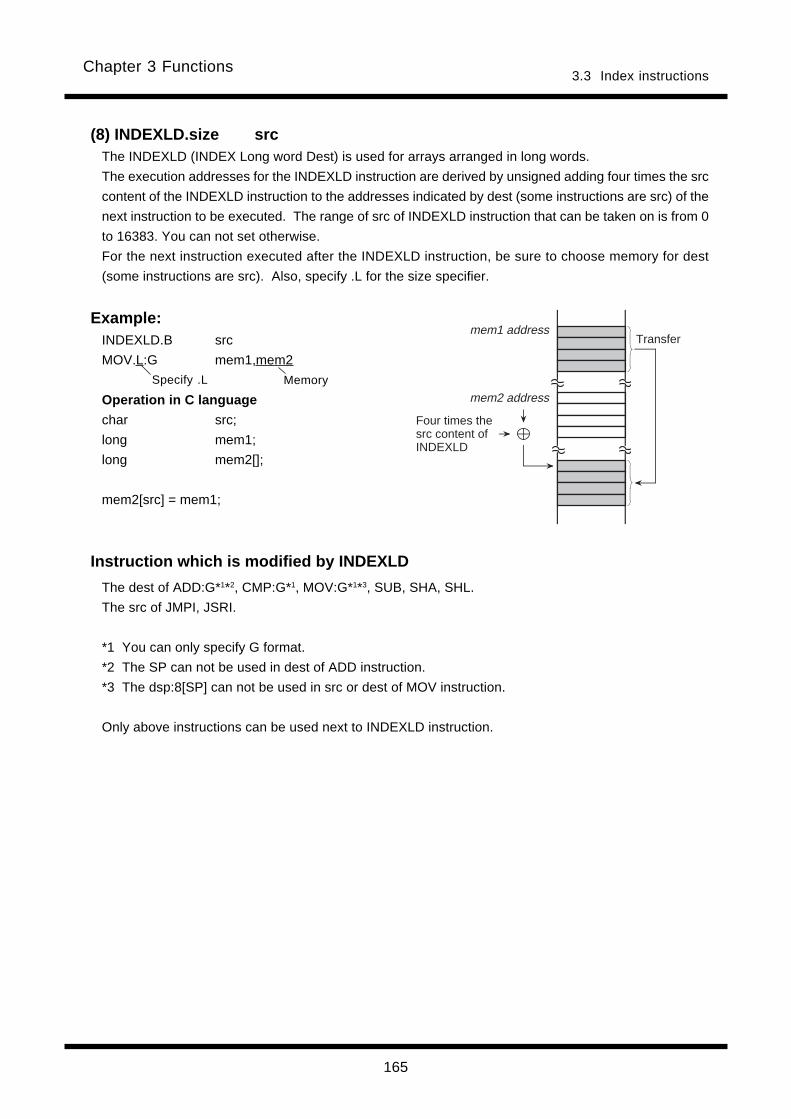
165
Chapter 3 Functions3.3 Index instructions
(8) INDEXLD.size srcThe INDEXLD (INDEX Long word Dest) is used for arrays arranged in long words.
The execution addresses for the INDEXLD instruction are derived by unsigned adding four times the src
content of the INDEXLD instruction to the addresses indicated by dest (some instructions are src) of the
next instruction to be executed. The range of src of INDEXLD instruction that can be taken on is from 0
to 16383. You can not set otherwise.
For the next instruction executed after the INDEXLD instruction, be sure to choose memory for dest
(some instructions are src). Also, specify .L for the size specifier.
Example:INDEXLD.B src
MOV.L:G mem1,mem2
Operation in C language
char src;
long mem1;
long mem2[];
mem2[src] = mem1;
Instruction which is modified by INDEXLD
The dest of ADD:G*1*2, CMP:G*1, MOV:G*1*3, SUB, SHA, SHL.
The src of JMPI, JSRI.
*1 You can only specify G format.
*2 The SP can not be used in dest of ADD instruction.
*3 The dsp:8[SP] can not be used in src or dest of MOV instruction.
Only above instructions can be used next to INDEXLD instruction.
MemorySpecify .L
AAAAAAAA
mem1 address
mem2 address
AAAAAAAAAAAAAAAAFour times the
src content of INDEXLD
Transfer
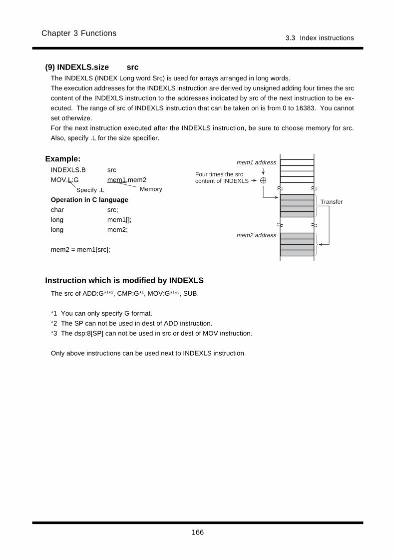
166
Chapter 3 Functions3.3 Index instructions
(9) INDEXLS.size srcThe INDEXLS (INDEX Long word Src) is used for arrays arranged in long words.
The execution addresses for the INDEXLS instruction are derived by unsigned adding four times the src
content of the INDEXLS instruction to the addresses indicated by src of the next instruction to be ex-
ecuted. The range of src of INDEXLS instruction that can be taken on is from 0 to 16383. You cannot
set otherwize.
For the next instruction executed after the INDEXLS instruction, be sure to choose memory for src.
Also, specify .L for the size specifier.
Example:INDEXLS.B src
MOV.L:G mem1,mem2
Operation in C language
char src;
long mem1[];
long mem2;
mem2 = mem1[src];
Instruction which is modified by INDEXLS
The src of ADD:G*1*2, CMP:G*1, MOV:G*1*3, SUB.
*1 You can only specify G format.
*2 The SP can not be used in dest of ADD instruction.
*3 The dsp:8[SP] can not be used in src or dest of MOV instruction.
Only above instructions can be used next to INDEXLS instruction.
MemorySpecify .L
mem1 address
mem2 address
AAAAAAAAAAAAAAAAAAAA
Four times the src content of INDEXLS
Transfer

167
Chapter 3 Functions3.3 Index instructions
(10) BITINDEX.size srcThe BITINDEX instruction is operated on the bit that is apart from bit 0 of the address indicated by dest
as many bits as indicated by src of BITINDEX.
Make sure the next instruction to be executed after BITINDEX is a bit instruction. Also, be sure to
specify memory for src or dest.
Example:
BITINDEX.B/W src
BSET 3,mem1
Instruction which is modified by BITINDEXThe src of BAND, BNAND, BNOR, BNTST, BNXOR, BOR, BTST:G*1, BXOR.
The dest of BCLR, BMcnd, BNOT, BSET, BTSTC, BTSTS.
*1 You can only specify G format.
Memory
Becomes invalid.
Bit instruction
AAAA
AAAA
mem1 address
Bit position
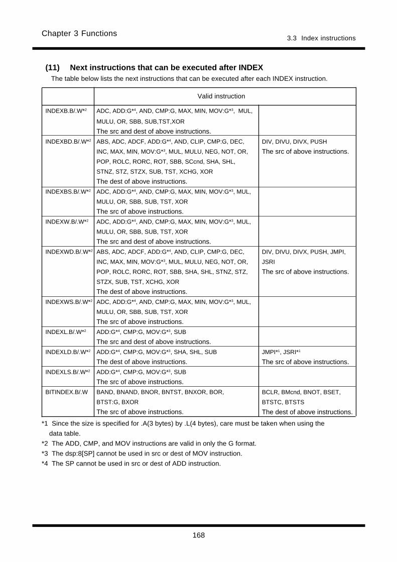
168
Chapter 3 Functions3.3 Index instructions
(11) Next instructions that can be executed after INDEXThe table below lists the next instructions that can be executed after each INDEX instruction.
INDEXB.B/.W*2 ADC, ADD:G*4, AND, CMP:G, MAX, MIN, MOV:G*3, MUL,
MULU, OR, SBB, SUB,TST,XOR
The src and dest of above instructions.
INDEXBD.B/.W*2 ABS, ADC, ADCF, ADD:G*4, AND, CLIP, CMP:G, DEC,
INC, MAX, MIN, MOV:G*3, MUL, MULU, NEG, NOT, OR,
POP, ROLC, RORC, ROT, SBB, SCcnd, SHA, SHL,
STNZ, STZ, STZX, SUB, TST, XCHG, XOR
The dest of above instructions.
INDEXBS.B/.W*2 ADC, ADD:G*4, AND, CMP:G, MAX, MIN, MOV:G*3, MUL,
MULU, OR, SBB, SUB, TST, XOR
The src of above instructions.
INDEXW.B/.W*2 ADC, ADD:G*4, AND, CMP:G, MAX, MIN, MOV:G*3, MUL,
MULU, OR, SBB, SUB, TST, XOR
The src and dest of above instructions.
INDEXWD.B/.W*2 ABS, ADC, ADCF, ADD:G*4, AND, CLIP, CMP:G, DEC,
INC, MAX, MIN, MOV:G*3, MUL, MULU, NEG, NOT, OR,
POP, ROLC, RORC, ROT, SBB, SHA, SHL, STNZ, STZ,
STZX, SUB, TST, XCHG, XOR
The dest of above instructions.
INDEXWS.B/.W*2 ADC, ADD:G*4, AND, CMP:G, MAX, MIN, MOV:G*3, MUL,
MULU, OR, SBB, SUB, TST, XOR
The src of above instructions.
INDEXL.B/.W*2 ADD:G*4, CMP:G, MOV:G*3, SUB
The src and dest of above instructions.
INDEXLD.B/.W*2 ADD:G*4, CMP:G, MOV:G*3, SHA, SHL, SUB
The dest of above instructions.
INDEXLS.B/.W*2 ADD:G*4, CMP:G, MOV:G*3, SUB
The src of above instructions.
BITINDEX.B/.W BAND, BNAND, BNOR, BNTST, BNXOR, BOR,
BTST:G, BXOR
The src of above instructions.
DIV, DIVU, DIVX, PUSH
The src of above instructions.
DIV, DIVU, DIVX, PUSH, JMPI,
JSRI
The src of above instructions.
JMPI*1, JSRI*1
The src of above instructions.
BCLR, BMcnd, BNOT, BSET,
BTSTC, BTSTS
The dest of above instructions.
Valid instruction
*1 Since the size is specified for .A(3 bytes) by .L(4 bytes), care must be taken when using the
data table.
*2 The ADD, CMP, and MOV instructions are valid in only the G format.
*3 The dsp:8[SP] cannot be used in src or dest of MOV instruction.
*4 The SP cannot be used in src or dest of ADD instruction.

169
Chapter 3 Functions3.3 Index instructions
(12) Addressing modesThe table below lists the addressing modes that become valid in the next instructions that can be ex-
ecuted after INDEX. Indirect addressing modes can be used in each instruction.
*1 For the MOV instruction you cannot use dsp8:[SP].
*2 The SP in the ADD instruction cannot be used.
*3 You cannot use R0L/R0/R2R0, R0H/R2/-, R1L/R1/R3R1, R1H/R3/-, SP/SP/SP, dsp:8[SP], and #IMM.
src dest
[A0] [A1]
dsp:8[A0] dsp:8[A1] dsp:8[SB] dsp:8[FB]
dsp:16[A0] dsp:16[A1] dsp:16[SB] dsp:16[FB]
dsp:24[A0] dsp:24[A1] abs24 abs16
[A0] [A1]
dsp:8[A0] dsp:8[A1] dsp:8[SB] dsp:8[FB]
dsp:16[A0] dsp:16[A1] dsp:16[SB] dsp:16[FB]
dsp:24[A0] dsp:24[A1] abs24 abs16

170
Chapter 3 Functions3.3 Index instructions
Chapter 4
Instruction Code/Number of Cycles
4.1 Guide to This Chapter
4.2 Instruction Code/Number of Cycles
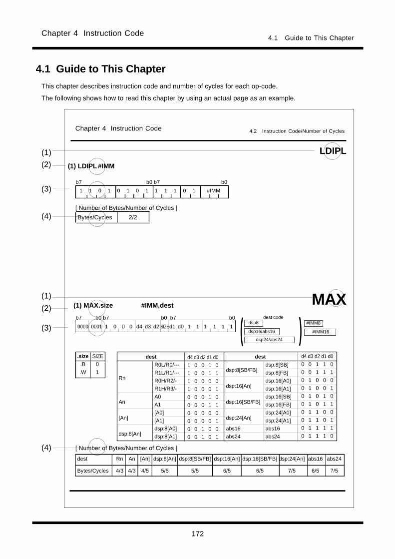
Chapter 4 Instruction Code4.1 Guide to This Chapter
172
b7 b0 b7 b0 b7 b0
4.1 Guide to This Chapter
This chapter describes instruction code and number of cycles for each op-code.
The following shows how to read this chapter by using an actual page as an example.
(1) LDIPL #IMM
LDIPL
(3)
(4)
(1)
(2)
(4)
(1)
(2)
(3)
b7 b0 b7 b0
1 1 0 1 0 1 0 1 1 1 1 0 1 #IMM
(1) MAX.size #IMM,dest MAX
[ Number of Bytes/Number of Cycles ]
.size
.B
.W
SIZE
0
1R0L/R0/---
R1L/R1/---
R0H/R2/-
R1H/R3/-
A0
A1
[A0]
[A1]
dsp:8[A0]
dsp:8[A1]
dsp:8[SB/FB]
dsp:16[An]
dsp:16[SB/FB]
dsp:24[An]
abs16
abs24
Rn
An
[An]
dsp:8[An]
destdest d4 d3 d2 d1 d0
1 0 0 1 0
1 0 0 1 1
1 0 0 0 0
1 0 0 0 1
0 0 0 1 0
0 0 0 1 1
0 0 0 0 0
0 0 0 0 1
0 0 1 0 0
0 0 1 0 1
d4 d3 d2 d1 d0
0 0 1 1 0
0 0 1 1 1
0 1 0 0 0
0 1 0 0 1
0 1 0 1 0
0 1 0 1 1
0 1 1 0 0
0 1 1 0 1
0 1 1 1 1
0 1 1 1 0
dsp:8[SB]
dsp:8[FB]
dsp:16[A0]
dsp:16[A1]
dsp:16[SB]
dsp:16[FB]
dsp:24[A0]
dsp:24[A1]
abs16
abs24
[ Number of Bytes/Number of Cycles ]
Bytes/Cycles 2/2
dsp24/abs24
dest codedsp8
dsp16/abs16 )( #IMM8
#IMM16
Chapter 4 Instruction Code 4.2 Instruction Code/Number of Cycles
0000 0001 1 0 0 0 d4 d3 d2 SIZEd1 d0 1 1 1 1 1 1
dest Rn An [An] dsp:8[An] dsp:8[SB/FB] dsp:16[An] dsp:16[SB/FB] dsp:24[An] abs16 abs24
Bytes/Cycles 4/3 4/3 4/5 5/5 5/5 6/5 6/5 7/5 6/5 7/5

Chapter 4 Instruction Code4.1 Guide to This Chapter
173
(1) MnemonicShows the mnemonic explained in this page.
(2) SyntaxShows an instruction syntax using symbols.
(3) Instruction codeShows instruction code. Entered in ( ) are omitted depending on src/dest you selected.
.size
.B
.W
SIZE
0
1
(4) Table of cyclesShows the number of cycles required to execute this instruction and the number of instruction bytes.The number of cycles shown are the minimum possible, and they vary depending on the following conditions:• Number of bytes that have been loaded in the instruction queue buffer• Accessing of an external memory using 8-bit external bus• Whether a wait is inserted in the bus cycleInstruction bytes are indicated on the left side of the slash and execution cycles are indicated on the right side.
R0L/R0/---
R1L/R1/---
R0H/R2/-
R1H/R3/-
A0
A1
[A0]
[A1]
dsp:8[A0]
dsp:8[A1]
dsp:8[SB/FB]
dsp:16[An]
dsp:16[SB/FB]
dsp:24[An]
abs16
abs24
Rn
An
[An]
dsp:8[An]
destdest d4 d3 d2 d1 d0
1 0 0 1 0
1 0 0 1 1
1 0 0 0 0
1 0 0 0 1
0 0 0 1 0
0 0 0 1 1
0 0 0 0 0
0 0 0 0 1
0 0 1 0 0
0 0 1 0 1
d4 d3 d2 d1 d0
0 0 1 1 0
0 0 1 1 1
0 1 0 0 0
0 1 0 0 1
0 1 0 1 0
0 1 0 1 1
0 1 1 0 0
0 1 1 0 1
0 1 1 1 1
0 1 1 1 0
dsp:8[SB]
dsp:8[FB]
dsp:16[A0]
dsp:16[A1]
dsp:16[SB]
dsp:16[FB]
dsp:24[A0]
dsp:24[A1]
abs16
abs24
dsp24/abs24
dest codedsp8
dsp16/abs16 )( #IMM8
#IMM160000 0001 1 0 0 0 d4d3d2SIZEd1d0 1 1 1 1 1 1
b7 b0 b7 b0b7 b0
Contents at addresses following (start
address of instruction + 2)(See the following figure.)
Content at startaddress ofinstruction
Content at (startaddress of instruc-
tion+1)
CorrespondenceCorrespondence
Correspondence
Contents at addresses following (start address of instruction + 2) are arranged as follows:
Content at (startaddress of instruc-
tion+2)
dsp8#IMM8
+0
+1
+2
8 bits
b7 b0b7 b0
b7 b0
dsp16abs16#IMM16
abs24dsp24#IMM24
Low-order 8 bits High-order 8 bits
b7 b0b7 b0
Low-order 8 bits Middle-order 8bits
b7 b0
High-order 8 bits
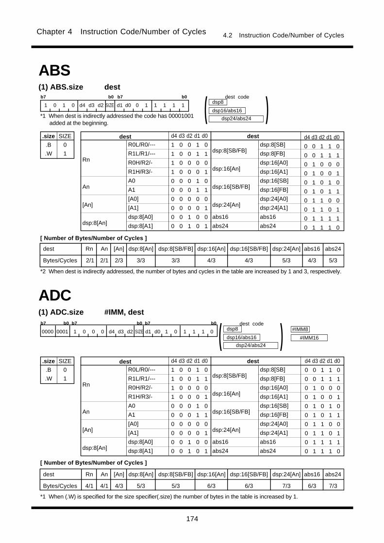
174
Chapter 4 Instruction Code/Number of Cycles 4.2 Instruction Code/Number of Cycles
ABS(1) ABS.size dest
.size
.B
.W
SIZE
0
1
b7 b0 b7 b0
1 0 1 0 d4 d3 d2 SIZE d1 d0 0 1 1 1 1 1
dest Rn An [An] dsp:8[An] dsp:8[SB/FB] dsp:16[An] dsp:16[SB/FB] dsp:24[An] abs16 abs24
Bytes/Cycles 2/1 2/1 2/3 3/3 3/3 4/3 4/3 5/3 4/3 5/3
R0L/R0/---
R1L/R1/---
R0H/R2/-
R1H/R3/-
A0
A1
[A0]
[A1]
dsp:8[A0]
dsp:8[A1]
dsp:8[SB/FB]
dsp:16[An]
dsp:16[SB/FB]
dsp:24[An]
abs16
abs24
Rn
An
[An]
dsp:8[An]
destdest d4 d3 d2 d1 d0
1 0 0 1 0
1 0 0 1 1
1 0 0 0 0
1 0 0 0 1
0 0 0 1 0
0 0 0 1 1
0 0 0 0 0
0 0 0 0 1
0 0 1 0 0
0 0 1 0 1
d4 d3 d2 d1 d0
0 0 1 1 0
0 0 1 1 1
0 1 0 0 0
0 1 0 0 1
0 1 0 1 0
0 1 0 1 1
0 1 1 0 0
0 1 1 0 1
0 1 1 1 1
0 1 1 1 0
dsp24/abs24
dest codedsp8
dsp16/abs16 )(dsp:8[SB]
dsp:8[FB]
dsp:16[A0]
dsp:16[A1]
dsp:16[SB]
dsp:16[FB]
dsp:24[A0]
dsp:24[A1]
abs16
abs24
ADC(1) ADC.size #IMM, dest
.size
.B
.W
SIZE
0
1
b7 b0 b7 b0 b7 b0
0000 0001 1 0 0 0 d4 d3 d2 SIZE d1 d0 1 0 1 1 1 0
dest Rn An [An] dsp:8[An] dsp:8[SB/FB] dsp:16[An] dsp:16[SB/FB] dsp:24[An] abs16 abs24
Bytes/Cycles 4/1 4/1 4/3 5/3 5/3 6/3 6/3 7/3 6/3 7/3
R0L/R0/---
R1L/R1/---
R0H/R2/-
R1H/R3/-
A0
A1
[A0]
[A1]
dsp:8[A0]
dsp:8[A1]
dsp:8[SB/FB]
dsp:16[An]
dsp:16[SB/FB]
dsp:24[An]
abs16
abs24
Rn
An
[An]
dsp:8[An]
destdest d4 d3 d2 d1 d0
1 0 0 1 0
1 0 0 1 1
1 0 0 0 0
1 0 0 0 1
0 0 0 1 0
0 0 0 1 1
0 0 0 0 0
0 0 0 0 1
0 0 1 0 0
0 0 1 0 1
d4 d3 d2 d1 d0
0 0 1 1 0
0 0 1 1 1
0 1 0 0 0
0 1 0 0 1
0 1 0 1 0
0 1 0 1 1
0 1 1 0 0
0 1 1 0 1
0 1 1 1 1
0 1 1 1 0
dsp24/abs24
dest codedsp8
dsp16/abs16 )(dsp:8[SB]
dsp:8[FB]
dsp:16[A0]
dsp:16[A1]
dsp:16[SB]
dsp:16[FB]
dsp:24[A0]
dsp:24[A1]
abs16
abs24
#IMM8
#IMM16
*1 When dest is indirectly addressed the code has 00001001added at the beginning.
*2 When dest is indirectly addressed, the number of bytes and cycles in the table are increased by 1 and 3, respectively.
*1 When (.W) is specified for the size specifier(.size) the number of bytes in the table is increased by 1.
[ Number of Bytes/Number of Cycles ]
[ Number of Bytes/Number of Cycles ]
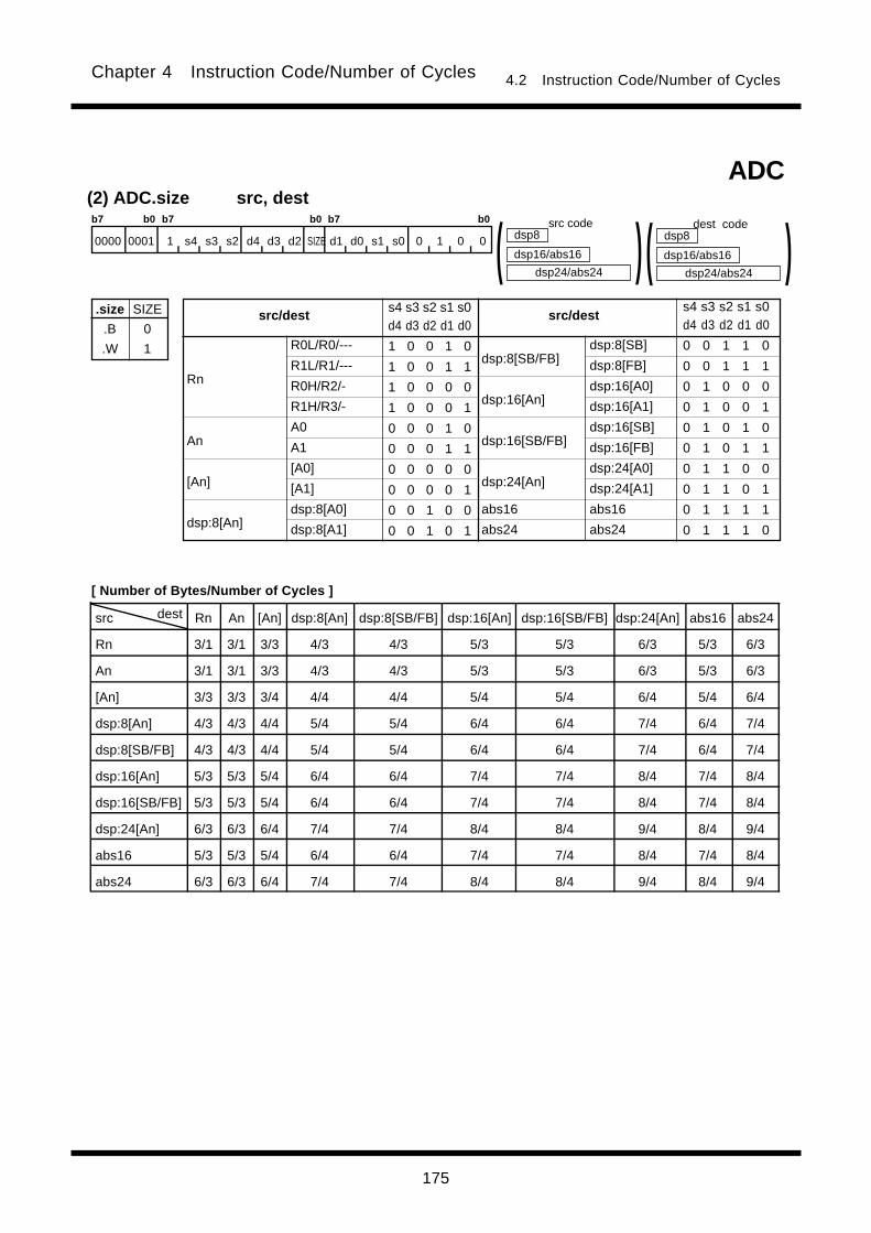
175
Chapter 4 Instruction Code/Number of Cycles 4.2 Instruction Code/Number of Cycles
(2) ADC.size src, dest
.size
.B
.W
SIZE
0
1 R0L/R0/---
R1L/R1/---
R0H/R2/-
R1H/R3/-
A0
A1
[A0]
[A1]
dsp:8[A0]
dsp:8[A1]
dsp:8[SB/FB]
dsp:16[An]
dsp:16[SB/FB]
dsp:24[An]
abs16
abs24
Rn
An
[An]
dsp:8[An]
src/destsrc/dests4 s3 s2 s1 s0d4 d3 d2 d1 d0
1 0 0 1 0
1 0 0 1 1
1 0 0 0 0
1 0 0 0 1
0 0 0 1 0
0 0 0 1 1
0 0 0 0 0
0 0 0 0 1
0 0 1 0 0
0 0 1 0 1
s4 s3 s2 s1 s0d4 d3 d2 d1 d0
0 0 1 1 0
0 0 1 1 1
0 1 0 0 0
0 1 0 0 1
0 1 0 1 0
0 1 0 1 1
0 1 1 0 0
0 1 1 0 1
0 1 1 1 1
0 1 1 1 0
dsp:8[SB]
dsp:8[FB]
dsp:16[A0]
dsp:16[A1]
dsp:16[SB]
dsp:16[FB]
dsp:24[A0]
dsp:24[A1]
abs16
abs24
ADC
b7 b0 b7 b0 b7 b0
0000 0001 1 s4 s3 s2 d4 d3 d2 SIZE d1 d0 s1 s0 0 1 0 0
dsp24/abs24
src codedsp8
dsp16/abs16 )( dsp24/abs24
dest codedsp8
dsp16/abs16 )(
src dest Rn An [An] dsp:8[An] dsp:8[SB/FB] dsp:16[An] dsp:16[SB/FB] dsp:24[An] abs16 abs24
Rn 3/1 3/1 3/3 4/3 4/3 5/3 5/3 6/3 5/3 6/3
An 3/1 3/1 3/3 4/3 4/3 5/3 5/3 6/3 5/3 6/3
[An] 3/3 3/3 3/4 4/4 4/4 5/4 5/4 6/4 5/4 6/4
dsp:8[An] 4/3 4/3 4/4 5/4 5/4 6/4 6/4 7/4 6/4 7/4
dsp:8[SB/FB] 4/3 4/3 4/4 5/4 5/4 6/4 6/4 7/4 6/4 7/4
dsp:16[An] 5/3 5/3 5/4 6/4 6/4 7/4 7/4 8/4 7/4 8/4
dsp:16[SB/FB] 5/3 5/3 5/4 6/4 6/4 7/4 7/4 8/4 7/4 8/4
dsp:24[An] 6/3 6/3 6/4 7/4 7/4 8/4 8/4 9/4 8/4 9/4
abs16 5/3 5/3 5/4 6/4 6/4 7/4 7/4 8/4 7/4 8/4
abs24 6/3 6/3 6/4 7/4 7/4 8/4 8/4 9/4 8/4 9/4
[ Number of Bytes/Number of Cycles ]
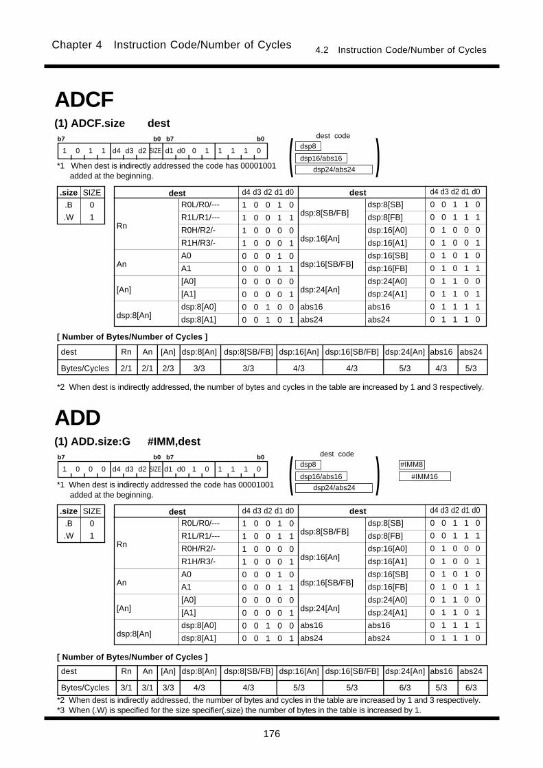
176
Chapter 4 Instruction Code/Number of Cycles 4.2 Instruction Code/Number of Cycles
(1) ADCF.size dest
.size
.B
.W
SIZE
0
1
b7 b0 b7 b0
1 0 1 1 d4 d3 d2 SIZE d1 d0 0 1 1 1 1 0
dest Rn An [An] dsp:8[An] dsp:8[SB/FB] dsp:16[An] dsp:16[SB/FB] dsp:24[An] abs16 abs24
Bytes/Cycles 2/1 2/1 2/3 3/3 3/3 4/3 4/3 5/3 4/3 5/3
R0L/R0/---
R1L/R1/---
R0H/R2/-
R1H/R3/-
A0
A1
[A0]
[A1]
dsp:8[A0]
dsp:8[A1]
dsp:8[SB/FB]
dsp:16[An]
dsp:16[SB/FB]
dsp:24[An]
abs16
abs24
Rn
An
[An]
dsp:8[An]
destdest d4 d3 d2 d1 d0
1 0 0 1 0
1 0 0 1 1
1 0 0 0 0
1 0 0 0 1
0 0 0 1 0
0 0 0 1 1
0 0 0 0 0
0 0 0 0 1
0 0 1 0 0
0 0 1 0 1
d4 d3 d2 d1 d0
0 0 1 1 0
0 0 1 1 1
0 1 0 0 0
0 1 0 0 1
0 1 0 1 0
0 1 0 1 1
0 1 1 0 0
0 1 1 0 1
0 1 1 1 1
0 1 1 1 0
dsp24/abs24
dsp8
dsp16/abs16 )(dsp:8[SB]
dsp:8[FB]
dsp:16[A0]
dsp:16[A1]
dsp:16[SB]
dsp:16[FB]
dsp:24[A0]
dsp:24[A1]
abs16
abs24
ADCF
(1) ADD.size:G #IMM,dest
.size
.B
.W
SIZE
0
1
b7 b0 b7 b0
1 0 0 0 d4 d3 d2 SIZE d1 d0 1 0 1 1 1 0
dest Rn An [An] dsp:8[An] dsp:8[SB/FB] dsp:16[An] dsp:16[SB/FB] dsp:24[An] abs16 abs24
Bytes/Cycles 3/1 3/1 3/3 4/3 4/3 5/3 5/3 6/3 5/3 6/3
R0L/R0/---
R1L/R1/---
R0H/R2/-
R1H/R3/-
A0
A1
[A0]
[A1]
dsp:8[A0]
dsp:8[A1]
dsp:8[SB/FB]
dsp:16[An]
dsp:16[SB/FB]
dsp:24[An]
abs16
abs24
Rn
An
[An]
dsp:8[An]
destdest d4 d3 d2 d1 d0
1 0 0 1 0
1 0 0 1 1
1 0 0 0 0
1 0 0 0 1
0 0 0 1 0
0 0 0 1 1
0 0 0 0 0
0 0 0 0 1
0 0 1 0 0
0 0 1 0 1
d4 d3 d2 d1 d0
0 0 1 1 0
0 0 1 1 1
0 1 0 0 0
0 1 0 0 1
0 1 0 1 0
0 1 0 1 1
0 1 1 0 0
0 1 1 0 1
0 1 1 1 1
0 1 1 1 0
dsp24/abs24
dsp8
dsp16/abs16 )(dsp:8[SB]
dsp:8[FB]
dsp:16[A0]
dsp:16[A1]
dsp:16[SB]
dsp:16[FB]
dsp:24[A0]
dsp:24[A1]
abs16
abs24
#IMM8
#IMM16
ADD
*1 When dest is indirectly addressed the code has 00001001added at the beginning.
dest code
[ Number of Bytes/Number of Cycles ]
*2 When dest is indirectly addressed, the number of bytes and cycles in the table are increased by 1 and 3 respectively.
*1 When dest is indirectly addressed the code has 00001001added at the beginning.
[ Number of Bytes/Number of Cycles ]
*2 When dest is indirectly addressed, the number of bytes and cycles in the table are increased by 1 and 3 respectively.*3 When (.W) is specified for the size specifier(.size) the number of bytes in the table is increased by 1.
dest code
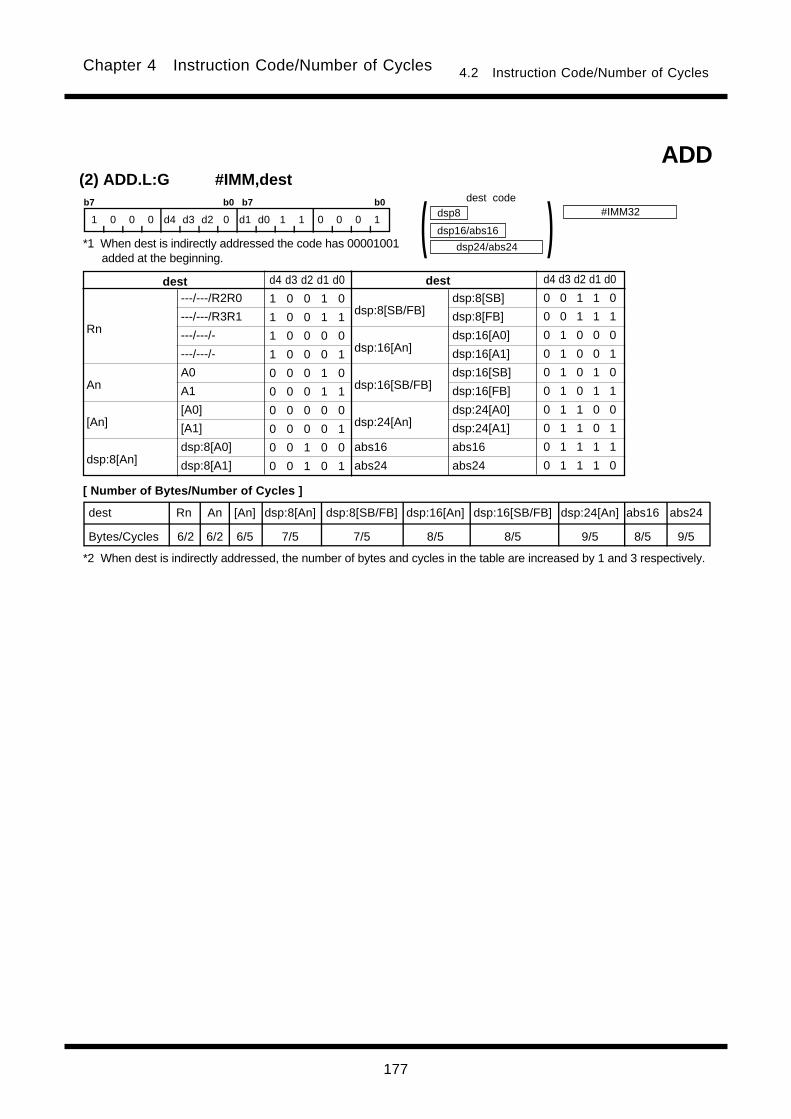
177
Chapter 4 Instruction Code/Number of Cycles 4.2 Instruction Code/Number of Cycles
(2) ADD.L:G #IMM,destb7 b0 b7 b0
1 0 0 0 d4 d3 d2 0 d1 d0 1 1 0 0 0 1
dest Rn An [An] dsp:8[An] dsp:8[SB/FB] dsp:16[An] dsp:16[SB/FB] dsp:24[An] abs16 abs24
Bytes/Cycles 6/2 6/2 6/5 7/5 7/5 8/5 8/5 9/5 8/5 9/5
---/---/R2R0
---/---/R3R1
---/---/-
---/---/-
A0
A1
[A0]
[A1]
dsp:8[A0]
dsp:8[A1]
dsp:8[SB/FB]
dsp:16[An]
dsp:16[SB/FB]
dsp:24[An]
abs16
abs24
Rn
An
[An]
dsp:8[An]
destdest d4 d3 d2 d1 d0
1 0 0 1 0
1 0 0 1 1
1 0 0 0 0
1 0 0 0 1
0 0 0 1 0
0 0 0 1 1
0 0 0 0 0
0 0 0 0 1
0 0 1 0 0
0 0 1 0 1
d4 d3 d2 d1 d0
0 0 1 1 0
0 0 1 1 1
0 1 0 0 0
0 1 0 0 1
0 1 0 1 0
0 1 0 1 1
0 1 1 0 0
0 1 1 0 1
0 1 1 1 1
0 1 1 1 0
dsp24/abs24
dsp8
dsp16/abs16 )(dsp:8[SB]
dsp:8[FB]
dsp:16[A0]
dsp:16[A1]
dsp:16[SB]
dsp:16[FB]
dsp:24[A0]
dsp:24[A1]
abs16
abs24
ADD
#IMM32dest code
*1 When dest is indirectly addressed the code has 00001001added at the beginning.
[ Number of Bytes/Number of Cycles ]
*2 When dest is indirectly addressed, the number of bytes and cycles in the table are increased by 1 and 3 respectively.

178
Chapter 4 Instruction Code/Number of Cycles 4.2 Instruction Code/Number of Cycles
(3) ADD.size:Q #IMM, dest
.size
.B
.W
.L
SIZE1
0
0
1
b7 b0 b7 b0
1 1 1 SIZE1 d4 d3 d2 SIZE2 d1 d0 1 1 IMM4
dest Rn An [An] dsp:8[An] dsp:8[SB/FB] dsp:16[An] dsp:16[SB/FB] dsp:24[An] abs16 abs24
Bytes/Cycles 2/1 2/1 2/3 3/3 3/3 4/3 4/3 5/3 4/3 5/3
0
+1
+2
+3
+4
+5
+6
+7
#IMM#IMM IMM4
0 0 0 0
0 0 0 1
0 0 1 0
0 0 1 1
0 1 0 0
0 1 0 1
0 1 1 0
0 1 1 1
IMM4
1 0 0 0
1 0 0 1
1 0 1 0
1 0 1 1
1 1 0 0
1 1 0 1
1 1 1 0
1 1 1 1
dsp24/abs24
dsp8
dsp16/abs16 )(ADD
R0L/R0/R2R0
R1L/R1/R3R1
R0H/R2/-
R1H/R3/-
A0
A1
[A0]
[A1]
dsp:8[A0]
dsp:8[A1]
dsp:8[SB/FB]
dsp:16[An]
dsp:16[SB/FB]
dsp:24[An]
abs16
abs24
Rn
An
[An]
dsp:8[An]
destdest d4 d3 d2 d1 d0
1 0 0 1 0
1 0 0 1 1
1 0 0 0 0
1 0 0 0 1
0 0 0 1 0
0 0 0 1 1
0 0 0 0 0
0 0 0 0 1
0 0 1 0 0
0 0 1 0 1
d4 d3 d2 d1 d0
0 0 1 1 0
0 0 1 1 1
0 1 0 0 0
0 1 0 0 1
0 1 0 1 0
0 1 0 1 1
0 1 1 0 0
0 1 1 0 1
0 1 1 1 1
0 1 1 1 0
dsp:8[SB]
dsp:8[FB]
dsp:16[A0]
dsp:16[A1]
dsp:16[SB]
dsp:16[FB]
dsp:24[A0]
dsp:24[A1]
abs16
abs24
-8
-7
-6
-5
-4
-3
-2
-1
SIZE2
0
1
0
dest Rn An [An] dsp:8[An] dsp:8[SB/FB] dsp:16[An] dsp:16[SB/FB] dsp:24[An] abs16 abs24
Bytes/Cycles 2/2 2/2 2/4 3/4 3/4 4/4 4/4 5/4 4/4 5/4
dest code
*1 When dest is indirectly addressed the code has 00001001added at the beginning.
[ Number of Bytes/Number of Cycles ]When (.B) and (.W) is specified for the size specifier (.size)
*2 When dest is indirectly addressed, the number of bytes and cycles in the table are increased by 1 and 3 respectively.
When (.L) is specified for the size specifier (.size)
*3 When dest is indirectly addressed, the number of bytes and cycles in the table are increased by 1 and 3 respectively.

179
Chapter 4 Instruction Code/Number of Cycles 4.2 Instruction Code/Number of Cycles
dest Rn dsp:8[SB/FB] abs16
Bytes/Cycles 2/1 3/3 4/3
(4) ADD.size:S #IMM, dest
.size
.B
.W
SIZE
0
1
b7 b0
0 0 d1 d0 0 1 1 SIZE
R0L/R0
dsp:8[SB]
dsp:8[FB]
abs16
Rn
dsp:8[SB/FB]
abs16
dest d1 d0
0 0
1 0
1 1
0 1
#IMM8
#IMM16
dsp8
abs16 )(ADD
(5) ADD.L:S #IMM, A0/A1
#IMM
#1
#2
IMM
0
1
b7 b0
1 0 IMM 0 1 1 0 d0
A0
A1
A0/A1 d0
0
1
ADD
Bytes/Cycles 1/2
*1 When dest is indirectly addressed the code has 00001001added at the beginning.
dest code
*2 When dest is indirectly addressed, the number of bytes and cycles in the table are increased by 1 and 3 respectively.*3 When (.W) is specified for the size specifier (.size) the number of bytes in the table is increased by 1.
[ Number of Bytes/Number of Cycles ]
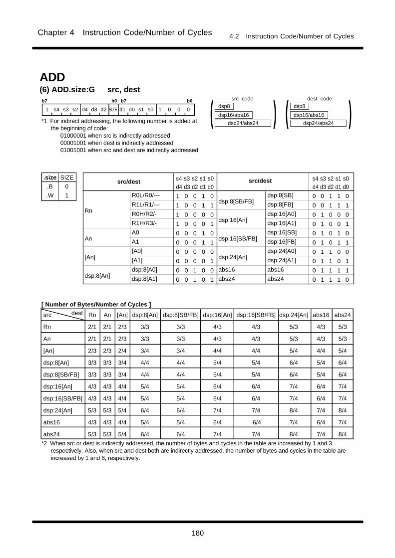
180
Chapter 4 Instruction Code/Number of Cycles 4.2 Instruction Code/Number of Cycles
src dest Rn An [An] dsp:8[An] dsp:8[SB/FB] dsp:16[An] dsp:16[SB/FB] dsp:24[An] abs16 abs24
Rn 2/1 2/1 2/3 3/3 3/3 4/3 4/3 5/3 4/3 5/3
An 2/1 2/1 2/3 3/3 3/3 4/3 4/3 5/3 4/3 5/3
[An] 2/3 2/3 2/4 3/4 3/4 4/4 4/4 5/4 4/4 5/4
dsp:8[An] 3/3 3/3 3/4 4/4 4/4 5/4 5/4 6/4 5/4 6/4
dsp:8[SB/FB] 3/3 3/3 3/4 4/4 4/4 5/4 5/4 6/4 5/4 6/4
dsp:16[An] 4/3 4/3 4/4 5/4 5/4 6/4 6/4 7/4 6/4 7/4
dsp:16[SB/FB] 4/3 4/3 4/4 5/4 5/4 6/4 6/4 7/4 6/4 7/4
dsp:24[An] 5/3 5/3 5/4 6/4 6/4 7/4 7/4 8/4 7/4 8/4
abs16 4/3 4/3 4/4 5/4 5/4 6/4 6/4 7/4 6/4 7/4
abs24 5/3 5/3 5/4 6/4 6/4 7/4 7/4 8/4 7/4 8/4
(6) ADD.size:G src, dest
.size
.B
.W
SIZE
0
1
b7 b0 b7 b0
1 s4 s3 s2 d4 d3 d2 SIZE d1 d0 s1 s0 1 0 0 0
R0L/R0/---
R1L/R1/---
R0H/R2/-
R1H/R3/-
A0
A1
[A0]
[A1]
dsp:8[A0]
dsp:8[A1]
dsp:8[SB/FB]
dsp:16[An]
dsp:16[SB/FB]
dsp:24[An]
abs16
abs24
Rn
An
[An]
dsp:8[An]
src/destsrc/dest s4 s3 s2 s1 s0d4 d3 d2 d1 d0
1 0 0 1 0
1 0 0 1 1
1 0 0 0 0
1 0 0 0 1
0 0 0 1 0
0 0 0 1 1
0 0 0 0 0
0 0 0 0 1
0 0 1 0 0
0 0 1 0 1
s4 s3 s2 s1 s0d4 d3 d2 d1 d0
0 0 1 1 0
0 0 1 1 1
0 1 0 0 0
0 1 0 0 1
0 1 0 1 0
0 1 0 1 1
0 1 1 0 0
0 1 1 0 1
0 1 1 1 1
0 1 1 1 0
dsp24/abs24
dsp8
dsp16/abs16 )(
dsp:8[SB]
dsp:8[FB]
dsp:16[A0]
dsp:16[A1]
dsp:16[SB]
dsp:16[FB]
dsp:24[A0]
dsp:24[A1]
abs16
abs24
dsp24/abs24
dsp8
dsp16/abs16 )(ADD
*1 For indirect addressing, the following number is added atthe beginning of code:
01000001 when src is indirectly addressed00001001 when dest is indirectly addressed01001001 when src and dest are indirectly addressed
dest codesrc code
[ Number of Bytes/Number of Cycles ]
*2 When src or dest is indirectly addressed, the number of bytes and cycles in the table are increased by 1 and 3respectively. Also, when src and dest both are indirectly addressed, the number of bytes and cycles in the table areincreased by 1 and 6, respectively.
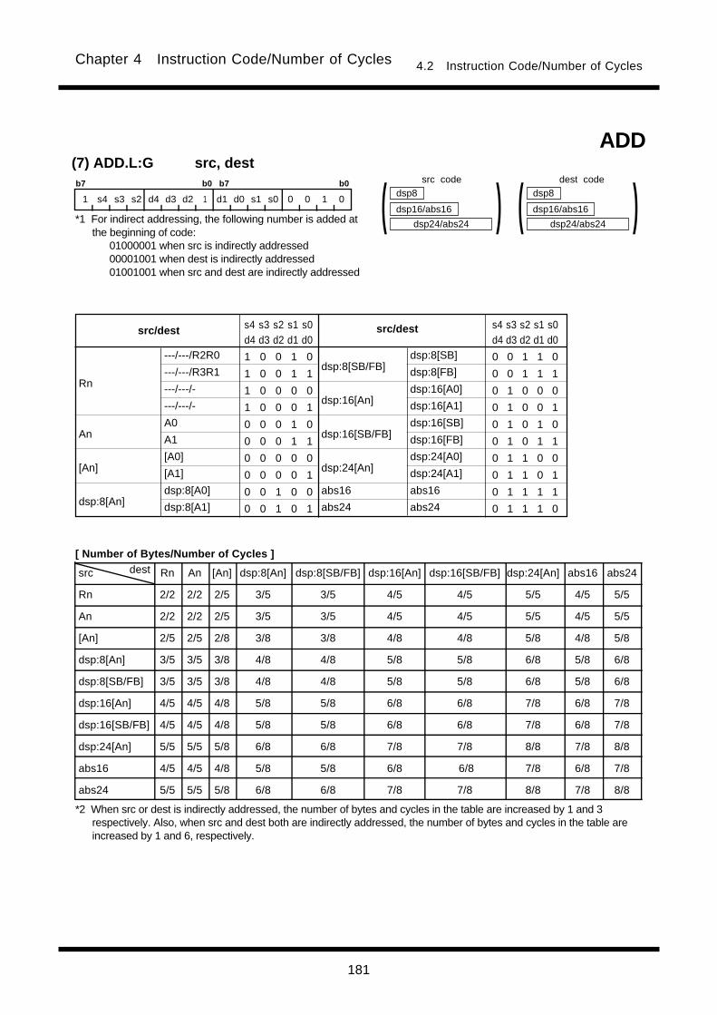
181
Chapter 4 Instruction Code/Number of Cycles 4.2 Instruction Code/Number of Cycles
src dest Rn An [An] dsp:8[An] dsp:8[SB/FB] dsp:16[An] dsp:16[SB/FB] dsp:24[An] abs16 abs24
Rn 2/2 2/2 2/5 3/5 3/5 4/5 4/5 5/5 4/5 5/5
An 2/2 2/2 2/5 3/5 3/5 4/5 4/5 5/5 4/5 5/5
[An] 2/5 2/5 2/8 3/8 3/8 4/8 4/8 5/8 4/8 5/8
dsp:8[An] 3/5 3/5 3/8 4/8 4/8 5/8 5/8 6/8 5/8 6/8
dsp:8[SB/FB] 3/5 3/5 3/8 4/8 4/8 5/8 5/8 6/8 5/8 6/8
dsp:16[An] 4/5 4/5 4/8 5/8 5/8 6/8 6/8 7/8 6/8 7/8
dsp:16[SB/FB] 4/5 4/5 4/8 5/8 5/8 6/8 6/8 7/8 6/8 7/8
dsp:24[An] 5/5 5/5 5/8 6/8 6/8 7/8 7/8 8/8 7/8 8/8
abs16 4/5 4/5 4/8 5/8 5/8 6/8 6/8 7/8 6/8 7/8
abs24 5/5 5/5 5/8 6/8 6/8 7/8 7/8 8/8 7/8 8/8
(7) ADD.L:G src, destb7 b0 b7 b0
1 s4 s3 s2 d4 d3 d2 1 d1 d0 s1 s0 0 0 1 0
---/---/R2R0
---/---/R3R1
---/---/-
---/---/-
A0
A1
[A0]
[A1]
dsp:8[A0]
dsp:8[A1]
dsp:8[SB/FB]
dsp:16[An]
dsp:16[SB/FB]
dsp:24[An]
abs16
abs24
Rn
An
[An]
dsp:8[An]
src/destsrc/dest s4 s3 s2 s1 s0d4 d3 d2 d1 d0
1 0 0 1 0
1 0 0 1 1
1 0 0 0 0
1 0 0 0 1
0 0 0 1 0
0 0 0 1 1
0 0 0 0 0
0 0 0 0 1
0 0 1 0 0
0 0 1 0 1
s4 s3 s2 s1 s0d4 d3 d2 d1 d0
0 0 1 1 0
0 0 1 1 1
0 1 0 0 0
0 1 0 0 1
0 1 0 1 0
0 1 0 1 1
0 1 1 0 0
0 1 1 0 1
0 1 1 1 1
0 1 1 1 0
dsp24/abs24
dsp8
dsp16/abs16 )(
dsp:8[SB]
dsp:8[FB]
dsp:16[A0]
dsp:16[A1]
dsp:16[SB]
dsp:16[FB]
dsp:24[A0]
dsp:24[A1]
abs16
abs24
dsp24/abs24
dsp8
dsp16/abs16 )(ADD
dest codesrc code
*1 For indirect addressing, the following number is added atthe beginning of code:
01000001 when src is indirectly addressed00001001 when dest is indirectly addressed01001001 when src and dest are indirectly addressed
[ Number of Bytes/Number of Cycles ]
*2 When src or dest is indirectly addressed, the number of bytes and cycles in the table are increased by 1 and 3respectively. Also, when src and dest both are indirectly addressed, the number of bytes and cycles in the table areincreased by 1 and 6, respectively.
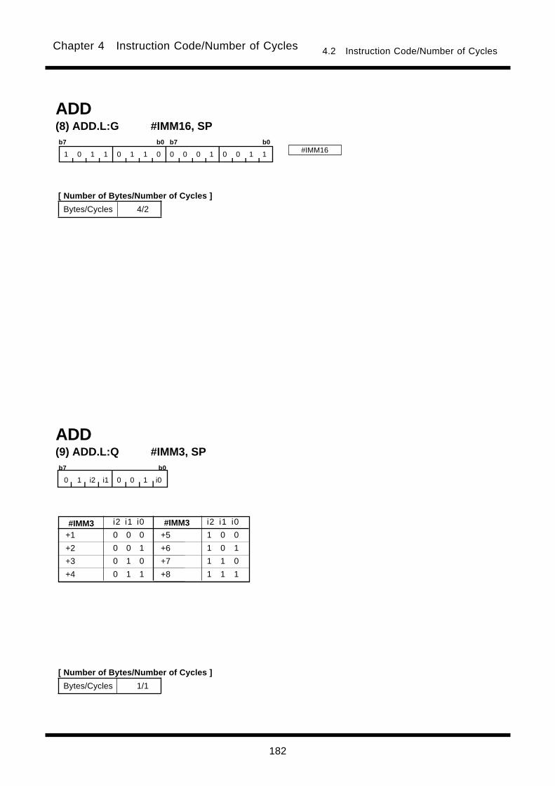
182
Chapter 4 Instruction Code/Number of Cycles 4.2 Instruction Code/Number of Cycles
+5
+6
+7
+8
(9) ADD.L:Q #IMM3, SPb7 b0
0 1 i2 i1 0 0 1 i0
ADD
+1
+2
+3
+4
#IMM3#IMM3 i2 i1 i0
0 0 0
0 0 1
0 1 0
0 1 1
i2 i1 i0
1 0 0
1 0 1
1 1 0
1 1 1
Bytes/Cycles 1/1
(8) ADD.L:G #IMM16, SPb7 b0 b7 b0
1 0 1 1 0 1 1 0 0 0 0 1 0 0 1 1 #IMM16
ADD
Bytes/Cycles 4/2
[ Number of Bytes/Number of Cycles ]
[ Number of Bytes/Number of Cycles ]

183
Chapter 4 Instruction Code/Number of Cycles 4.2 Instruction Code/Number of Cycles
(1) ADDX #IMM, destb7 b0 b7 b0
1 0 0 0 d4 d3 d2 0 d1 d0 0 1 0 0 0 1
dest Rn An [An] dsp:8[An] dsp:8[SB/FB] dsp:16[An] dsp:16[SB/FB] dsp:24[An] abs16 abs24
Bytes/Cycles 3/2 3/2 3/5 4/5 4/5 5/5 5/5 6/5 5/5 6/5
dsp24/abs24
dsp8
dsp16/abs16 )(ADDX
---/---/R2R0
---/---/R3R1
---/---/-
---/---/-
A0
A1
[A0]
[A1]
dsp:8[A0]
dsp:8[A1]
dsp:8[SB/FB]
dsp:16[An]
dsp:16[SB/FB]
dsp:24[An]
abs16
abs24
Rn
An
[An]
dsp:8[An]
destdest d4 d3 d2 d1 d0
1 0 0 1 0
1 0 0 1 1
1 0 0 0 0
1 0 0 0 1
0 0 0 1 0
0 0 0 1 1
0 0 0 0 0
0 0 0 0 1
0 0 1 0 0
0 0 1 0 1
d4 d3 d2 d1 d0
0 0 1 1 0
0 0 1 1 1
0 1 0 0 0
0 1 0 0 1
0 1 0 1 0
0 1 0 1 1
0 1 1 0 0
0 1 1 0 1
0 1 1 1 1
0 1 1 1 0
dsp:8[SB]
dsp:8[FB]
dsp:16[A0]
dsp:16[A1]
dsp:16[SB]
dsp:16[FB]
dsp:24[A0]
dsp:24[A1]
abs16
abs24
#IMM8
(10) ADD.L:S #IMM8, SPb7 b0 b7 b0
1 0 1 1 0 1 1 0 0 0 0 0 0 0 1 1
Bytes/Cycles 3/2
#IMM8
[ Number of Bytes/Number of Cycles ]
*1 When dest is indirectly addressed the code has 00001001added at the beginning.
[ Number of Bytes/Number of Cycles ]
dest code
*2 When dest is indirectly addressed, the number of bytes and cycles in the table are increased by 1 and 3 respectively.
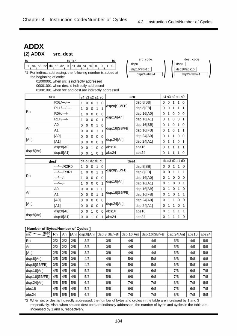
184
Chapter 4 Instruction Code/Number of Cycles 4.2 Instruction Code/Number of Cycles
src dest Rn An [An] dsp:8[An] dsp:8[SB/FB] dsp:16[An] dsp:16[SB/FB] dsp:24[An] abs16 abs24
Rn 2/2 2/2 2/5 3/5 3/5 4/5 4/5 5/5 4/5 5/5
An 2/2 2/2 2/5 3/5 3/5 4/5 4/5 5/5 4/5 5/5
[An] 2/5 2/5 2/8 3/8 3/8 4/8 4/8 5/8 4/8 5/8
dsp:8[An] 3/5 3/5 3/8 4/8 4/8 5/8 5/8 6/8 5/8 6/8
dsp:8[SB/FB] 3/5 3/5 3/8 4/8 4/8 5/8 5/8 6/8 5/8 6/8
dsp:16[An] 4/5 4/5 4/8 5/8 5/8 6/8 6/8 7/8 6/8 7/8
dsp:16[SB/FB] 4/5 4/5 4/8 5/8 5/8 6/8 6/8 7/8 6/8 7/8
dsp:24[An] 5/5 5/5 5/8 6/8 6/8 7/8 7/8 8/8 7/8 8/8
abs16 4/5 4/5 4/8 5/8 5/8 6/8 6/8 7/8 6/8 7/8
abs24 5/5 5/5 5/8 6/8 6/8 7/8 7/8 8/8 7/8 8/8
(2) ADDX src, destb7 b0 b7 b0
1 s4 s3 s2 d4 d3 d2 0 d1 d0 s1 s0 0 0 1 0
R0L/---/---
R1L/---/---
R0H/---/-
R1H/---/-
A0
A1
[A0]
[A1]
dsp:8[A0]
dsp:8[A1]
dsp:8[SB/FB]
dsp:16[An]
dsp:16[SB/FB]
dsp:24[An]
abs16
abs24
Rn
An
[An]
dsp:8[An]
srcsrc s4 s3 s2 s1 s0
1 0 0 1 0
1 0 0 1 1
1 0 0 0 0
1 0 0 0 1
0 0 0 1 0
0 0 0 1 1
0 0 0 0 0
0 0 0 0 1
0 0 1 0 0
0 0 1 0 1
s4 s3 s2 s1 s0
0 0 1 1 0
0 0 1 1 1
0 1 0 0 0
0 1 0 0 1
0 1 0 1 0
0 1 0 1 1
0 1 1 0 0
0 1 1 0 1
0 1 1 1 1
0 1 1 1 0
dsp24/abs24
dsp8
dsp16/abs16 )(
dsp:8[SB]
dsp:8[FB]
dsp:16[A0]
dsp:16[A1]
dsp:16[SB]
dsp:16[FB]
dsp:24[A0]
dsp:24[A1]
abs16
abs24
dsp24/abs24
dsp8
dsp16/abs16 )(ADDX
---/---/R2R0
---/---/R3R1
---/---/-
---/---/-
A0
A1
[A0]
[A1]
dsp:8[A0]
dsp:8[A1]
dsp:8[SB/FB]
dsp:16[An]
dsp:16[SB/FB]
dsp:24[An]
abs16
abs24
Rn
An
[An]
dsp:8[An]
destdest d4 d3 d2 d1 d0
1 0 0 1 0
1 0 0 1 1
1 0 0 0 0
1 0 0 0 1
0 0 0 1 0
0 0 0 1 1
0 0 0 0 0
0 0 0 0 1
0 0 1 0 0
0 0 1 0 1
d4 d3 d2 d1 d0
0 0 1 1 0
0 0 1 1 1
0 1 0 0 0
0 1 0 0 1
0 1 0 1 0
0 1 0 1 1
0 1 1 0 0
0 1 1 0 1
0 1 1 1 1
0 1 1 1 0
dsp:8[SB]
dsp:8[FB]
dsp:16[A0]
dsp:16[A1]
dsp:16[SB]
dsp:16[FB]
dsp:24[A0]
dsp:24[A1]
abs16
abs24
src code dest code
*1 For indirect addressing, the following number is added atthe beginning of code:
01000001 when src is indirectly addressed00001001 when dest is indirectly addressed01001001 when src and dest are indirectly addressed
[ Number of Bytes/Number of Cycles ]
*2 When src or dest is indirectly addressed, the number of bytes and cycles in the table are increased by 1 and 3respectively. Also, when src and dest both are indirectly addressed, the number of bytes and cycles in the table areincreased by 1 and 6, respectively.
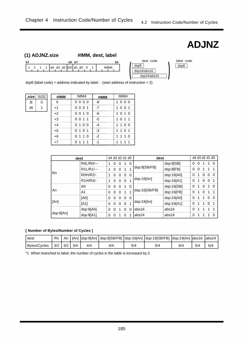
185
Chapter 4 Instruction Code/Number of Cycles 4.2 Instruction Code/Number of Cycles
(1) ADJNZ.size #IMM, dest, label
.size
.B
.W
SIZE
0
1
b7 b0 b7 b0
1 1 1 1 d4 d3 d2 SIZE d1 d0 0 1 IMM4
dest Rn An [An] dsp:8[An] dsp:8[SB/FB] dsp:16[An] dsp:16[SB/FB] dsp:24[An] abs16 abs24
Bytes/Cycles 3/2 3/2 3/4 4/4 4/4 5/4 5/4 6/4 5/4 6/4
0
+1
+2
+3
+4
+5
+6
+7
#IMM#IMM IMM4
0 0 0 0
0 0 0 1
0 0 1 0
0 0 1 1
0 1 0 0
0 1 0 1
0 1 1 0
0 1 1 1
IMM4
1 0 0 0
1 0 0 1
1 0 1 0
1 0 1 1
1 1 0 0
1 1 0 1
1 1 1 0
1 1 1 1
dsp24/abs24
dsp8
dsp16/abs16 )(ADJNZ
R0L/R0/---
R1L/R1/---
R0H/R2/-
R1H/R3/-
A0
A1
[A0]
[A1]
dsp:8[A0]
dsp:8[A1]
dsp:8[SB/FB]
dsp:16[An]
dsp:16[SB/FB]
dsp:24[An]
abs16
abs24
Rn
An
[An]
dsp:8[An]
destdest d4 d3 d2 d1 d0
1 0 0 1 0
1 0 0 1 1
1 0 0 0 0
1 0 0 0 1
0 0 0 1 0
0 0 0 1 1
0 0 0 0 0
0 0 0 0 1
0 0 1 0 0
0 0 1 0 1
d4 d3 d2 d1 d0
0 0 1 1 0
0 0 1 1 1
0 1 0 0 0
0 1 0 0 1
0 1 0 1 0
0 1 0 1 1
0 1 1 0 0
0 1 1 0 1
0 1 1 1 1
0 1 1 1 0
dsp:8[SB]
dsp:8[FB]
dsp:16[A0]
dsp:16[A1]
dsp:16[SB]
dsp:16[FB]
dsp:24[A0]
dsp:24[A1]
abs16
abs24
-8
-7
-6
-5
-4
-3
-2
-1
dsp8
dsp8 (label code) = address indicated by label - (start address of instruction + 2)
*1 When branched to label, the number of cycles in the table is increased by 2.
dest code label code
[ Number of Bytes/Number of Cycles ]
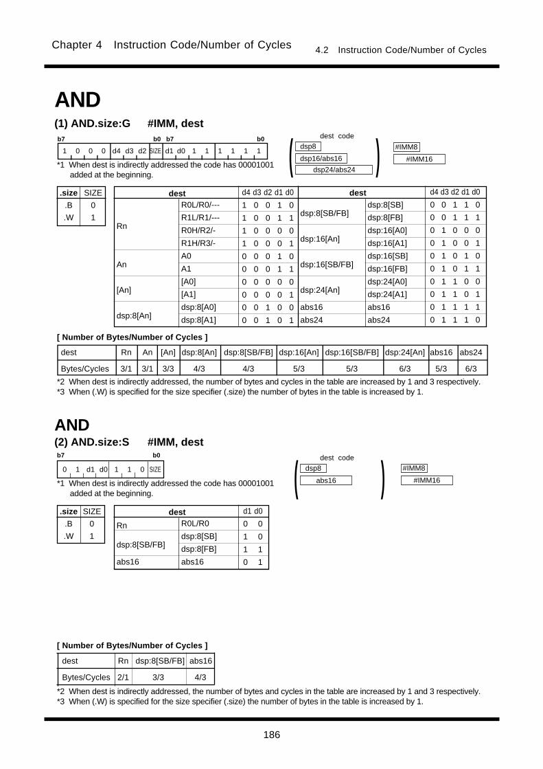
186
Chapter 4 Instruction Code/Number of Cycles 4.2 Instruction Code/Number of Cycles
(1) AND.size:G #IMM, dest
.size
.B
.W
SIZE
0
1
b7 b0 b7 b0
1 0 0 0 d4 d3 d2 SIZE d1 d0 1 1 1 1 1 1
dest Rn An [An] dsp:8[An] dsp:8[SB/FB] dsp:16[An] dsp:16[SB/FB] dsp:24[An] abs16 abs24
Bytes/Cycles 3/1 3/1 3/3 4/3 4/3 5/3 5/3 6/3 5/3 6/3
dsp24/abs24
dsp8
dsp16/abs16 )(AND
R0L/R0/---
R1L/R1/---
R0H/R2/-
R1H/R3/-
A0
A1
[A0]
[A1]
dsp:8[A0]
dsp:8[A1]
dsp:8[SB/FB]
dsp:16[An]
dsp:16[SB/FB]
dsp:24[An]
abs16
abs24
Rn
An
[An]
dsp:8[An]
destdest d4 d3 d2 d1 d0
1 0 0 1 0
1 0 0 1 1
1 0 0 0 0
1 0 0 0 1
0 0 0 1 0
0 0 0 1 1
0 0 0 0 0
0 0 0 0 1
0 0 1 0 0
0 0 1 0 1
d4 d3 d2 d1 d0
0 0 1 1 0
0 0 1 1 1
0 1 0 0 0
0 1 0 0 1
0 1 0 1 0
0 1 0 1 1
0 1 1 0 0
0 1 1 0 1
0 1 1 1 1
0 1 1 1 0
dsp:8[SB]
dsp:8[FB]
dsp:16[A0]
dsp:16[A1]
dsp:16[SB]
dsp:16[FB]
dsp:24[A0]
dsp:24[A1]
abs16
abs24
#IMM8
#IMM16
dest Rn dsp:8[SB/FB] abs16
Bytes/Cycles 2/1 3/3 4/3
(2) AND.size:S #IMM, dest
.size
.B
.W
SIZE
0
1
b7 b0
0 1 d1 d0 1 1 0 SIZE
R0L/R0
dsp:8[SB]
dsp:8[FB]
abs16
Rn
dsp:8[SB/FB]
abs16
dest d1 d0
0 0
1 0
1 1
0 1
#IMM8
#IMM16
dsp8
abs16 )(AND
dest code
*1 When dest is indirectly addressed the code has 00001001added at the beginning.
[ Number of Bytes/Number of Cycles ]
*2 When dest is indirectly addressed, the number of bytes and cycles in the table are increased by 1 and 3 respectively.*3 When (.W) is specified for the size specifier (.size) the number of bytes in the table is increased by 1.
*1 When dest is indirectly addressed the code has 00001001added at the beginning.
dest code
[ Number of Bytes/Number of Cycles ]
*2 When dest is indirectly addressed, the number of bytes and cycles in the table are increased by 1 and 3 respectively.*3 When (.W) is specified for the size specifier (.size) the number of bytes in the table is increased by 1.
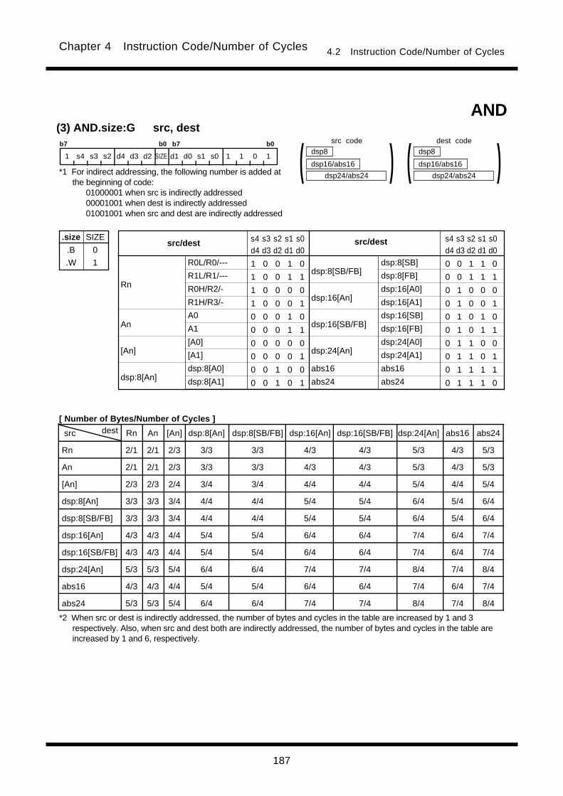
187
Chapter 4 Instruction Code/Number of Cycles 4.2 Instruction Code/Number of Cycles
src dest Rn An [An] dsp:8[An] dsp:8[SB/FB] dsp:16[An] dsp:16[SB/FB] dsp:24[An] abs16 abs24
Rn 2/1 2/1 2/3 3/3 3/3 4/3 4/3 5/3 4/3 5/3
An 2/1 2/1 2/3 3/3 3/3 4/3 4/3 5/3 4/3 5/3
[An] 2/3 2/3 2/4 3/4 3/4 4/4 4/4 5/4 4/4 5/4
dsp:8[An] 3/3 3/3 3/4 4/4 4/4 5/4 5/4 6/4 5/4 6/4
dsp:8[SB/FB] 3/3 3/3 3/4 4/4 4/4 5/4 5/4 6/4 5/4 6/4
dsp:16[An] 4/3 4/3 4/4 5/4 5/4 6/4 6/4 7/4 6/4 7/4
dsp:16[SB/FB] 4/3 4/3 4/4 5/4 5/4 6/4 6/4 7/4 6/4 7/4
dsp:24[An] 5/3 5/3 5/4 6/4 6/4 7/4 7/4 8/4 7/4 8/4
abs16 4/3 4/3 4/4 5/4 5/4 6/4 6/4 7/4 6/4 7/4
abs24 5/3 5/3 5/4 6/4 6/4 7/4 7/4 8/4 7/4 8/4
(3) AND.size:G src, dest
.size
.B
.W
SIZE
0
1
b7 b0 b7 b0
1 s4 s3 s2 d4 d3 d2 SIZE d1 d0 s1 s0 1 1 0 1
R0L/R0/---
R1L/R1/---
R0H/R2/-
R1H/R3/-
A0
A1
[A0]
[A1]
dsp:8[A0]
dsp:8[A1]
dsp:8[SB/FB]
dsp:16[An]
dsp:16[SB/FB]
dsp:24[An]
abs16
abs24
Rn
An
[An]
dsp:8[An]
src/destsrc/dest s4 s3 s2 s1 s0d4 d3 d2 d1 d0
1 0 0 1 0
1 0 0 1 1
1 0 0 0 0
1 0 0 0 1
0 0 0 1 0
0 0 0 1 1
0 0 0 0 0
0 0 0 0 1
0 0 1 0 0
0 0 1 0 1
s4 s3 s2 s1 s0d4 d3 d2 d1 d0
0 0 1 1 0
0 0 1 1 1
0 1 0 0 0
0 1 0 0 1
0 1 0 1 0
0 1 0 1 1
0 1 1 0 0
0 1 1 0 1
0 1 1 1 1
0 1 1 1 0
dsp24/abs24
dsp8
dsp16/abs16 )(
dsp:8[SB]
dsp:8[FB]
dsp:16[A0]
dsp:16[A1]
dsp:16[SB]
dsp:16[FB]
dsp:24[A0]
dsp:24[A1]
abs16
abs24
dsp24/abs24
dsp8
dsp16/abs16 )(AND
src code dest code
*1 For indirect addressing, the following number is added atthe beginning of code:
01000001 when src is indirectly addressed00001001 when dest is indirectly addressed01001001 when src and dest are indirectly addressed
[ Number of Bytes/Number of Cycles ]
*2 When src or dest is indirectly addressed, the number of bytes and cycles in the table are increased by 1 and 3respectively. Also, when src and dest both are indirectly addressed, the number of bytes and cycles in the table areincreased by 1 and 6, respectively.

188
Chapter 4 Instruction Code/Number of Cycles 4.2 Instruction Code/Number of Cycles
bit,Rn
3/2
BAND(1) BAND src
src
Bytes/Cycles
bit,R0L
bit,R0H
bit,R1L
bit,R1H
bit,A0
bit,A1
bit,[A0]
bit,[A1]
bit,base:11[A0]
bit,base:11[A1]
bit,base:11[SB/FB]
bit,base:19[An]
bit,base:19[SB/FB]
bit,base:27[An]
bit,base:19
bit,base:27
Rn
An
[An]
bit,base:11[An]
srcsrc s4 s3 s2 s1 s0
1 0 0 1 0
1 0 0 0 0
1 0 0 1 1
1 0 0 0 1
0 0 0 1 0
0 0 0 1 1
0 0 0 0 0
0 0 0 0 1
0 0 1 0 0
0 0 1 0 1
s4 s3 s2 s1 s0
0 0 1 1 0
0 0 1 1 1
0 1 0 0 0
0 1 0 0 1
0 1 0 1 0
0 1 0 1 1
0 1 1 0 0
0 1 1 0 1
0 1 1 1 1
0 1 1 1 0
bit,base:11[SB]
bit,base:11[FB]
bit,base:19[A0]
bit,base:19[A1]
bit,base:19[SB]
bit,base:19[FB]
bit,base:27[A0]
bit,base:27[A1]
bit,base:19
bit,base:27
BCLR
b7 b0 b7 b0 b7 b0
0000 0001 1 1 0 1 s4 s3 s2 0 s1 s0 0 0 1 BIT
dsp24/abs24
dsp8
dsp16/abs16 )(
bit,An
3/2
bit,[An]
3/4
bit,base:11[An]
4/4
bit,base:11[SB/FB]
4/4
bit,base:19[An]
5/4
bit,base:19[SB/FB]
5/4
bit,base:27[An]
6/4
bit,base:19
5/4
bit,base:27
6/4
bit,Rn
2/1
(1) BCLR dest
dest
Bytes/Cycles
bit,R0L
bit,R0H
bit,R1L
bit,R1H
bit,A0
bit,A1
bit,[A0]
bit,[A1]
bit,base:11[A0]
bit,base:11[A1]
bit,base:11[SB/FB]
bit,base:27[An]
bit,base:19[SB/FB]
bit,base:27[An]
bit,base:19
bit,base:27
Rn
An
[An]
bit,base:11[An]
destdest d4 d3 d2 d1 d0
1 0 0 1 0
1 0 0 0 0
1 0 0 1 1
1 0 0 0 1
0 0 0 1 0
0 0 0 1 1
0 0 0 0 0
0 0 0 0 1
0 0 1 0 0
0 0 1 0 1
d4 d3 d2 d1 d0
0 0 1 1 0
0 0 1 1 1
0 1 0 0 0
0 1 0 0 1
0 1 0 1 0
0 1 0 1 1
0 1 1 0 0
0 1 1 0 1
0 1 1 1 1
0 1 1 1 0
bit,base:11[SB]
bit,base:11[FB]
bit,base:19[A0]
bit,base:19[A1]
bit,base:19[SB]
bit,base:19[FB]
bit,base:27[A0]
bit,base:27[A1]
bit,base:19
bit,base:27
dsp24/abs24
dsp8
dsp16/abs16 )(
bit,An
2/1
bit,[An]
2/3
bit,base:11[An]
3/3
bit,base:11[SB/FB]
3/3
bit,base:19[An]
4/3
bit,base:19[SB/FB]
4/3
bit,base:27[An]
5/3
bit,base:19
4/3
bit,base:27
5/3
b7 b0 b7 b0
1 1 0 1 d4 d3 d2 0 d1 d0 1 1 0 BIT
src code
[Number of Bytes/Number of Cycles]
dest code
[Number of Bytes/Number of Cycles]

189
Chapter 4 Instruction Code/Number of Cycles 4.2 Instruction Code/Number of Cycles
BITINDEX(1) BITINDEX.size src
dsp24/abs24
dsp8
dsp16/abs16 )(b7 b0 b7 b0
1 1 0 0 d4 d3 d2 SIZE d1 d0 1 0 1 1 1 0
.size
.B
.W
SIZE
0
1R0L/R0/---
R1L/R1/---
R0H/R2/-
R1H/R3/-
A0
A1
[A0]
[A1]
dsp:8[A0]
dsp:8[A1]
dsp:8[SB/FB]
dsp:16[An]
dsp:16[SB/FB]
dsp:24[An]
abs16
abs24
Rn
An
[An]
dsp:8[An]
srcsrc s4 s3 s2 s1 s0
1 0 0 1 0
1 0 0 1 1
1 0 0 0 0
1 0 0 0 1
0 0 0 1 0
0 0 0 1 1
0 0 0 0 0
0 0 0 0 1
0 0 1 0 0
0 0 1 0 1
s4 s3 s2 s1 s0
0 0 1 1 0
0 0 1 1 1
0 1 0 0 0
0 1 0 0 1
0 1 0 1 0
0 1 0 1 1
0 1 1 0 0
0 1 1 0 1
0 1 1 1 1
0 1 1 1 0
dsp:8[SB]
dsp:8[FB]
dsp:16[A0]
dsp:16[A1]
dsp:16[SB]
dsp:16[FB]
dsp:24[A0]
dsp:24[A1]
abs16
abs24
*1 The cycles of next instruction to be executed is increased by 1.
src code
[Number of Bytes/Number of Cycles]
src Rn An [An] dsp:8[An] dsp:8[SB/FB] dsp:16[An] dsp:16[SB/FB] dsp:24[An] abs16 abs24
Bytes/Cycles 2/4 2/4 2/6 3/3 3/6 4/6 4/6 5/6 4/6 5/6

190
Chapter 4 Instruction Code/Number of Cycles 4.2 Instruction Code/Number of Cycles
GEU/C
GTU
EQ/Z
N
O
LE
LT
(1) BMcnd dest
BMcnd
bit,Rn
3/3
dest
Bytes/Cycles
bit,R0L
bit,R0H
bit,R1L
bit,R1H
bit,A0
bit,A1
bit,[A0]
bit,[A1]
bit,base:11[A0]
bit,base:11[A1]
bit,base:11[SB/FB]
bit,base:19[An]
bit,base:19[SB/FB]
bit,base:27[An]
bit,base:19
bit,base:27
Rn
An
[An]
bit,base:11[An]
destdest d4 d3 d2 d1 d0
1 0 0 1 0
1 0 0 0 0
1 0 0 1 1
1 0 0 0 1
0 0 0 1 0
0 0 0 1 1
0 0 0 0 0
0 0 0 0 1
0 0 1 0 0
0 0 1 0 1
d4 d3 d2 d1 d0
0 0 1 1 0
0 0 1 1 1
0 1 0 0 0
0 1 0 0 1
0 1 0 1 0
0 1 0 1 1
0 1 1 0 0
0 1 1 0 1
0 1 1 1 1
0 1 1 1 0
bit,base:11[SB]
bit,base:11[FB]
bit,base:19[A0]
bit,base:19[A1]
bit,base:19[SB]
bit,base:19[FB]
bit,base:27[A0]
bit,base:27[A1]
bit,base:19
bit,base:27
dsp24/abs24
dsp8
dsp16/abs16 )(
bit,An
3/3
bit,[An]
3/4
bit,base:11[An]
4/4
bit,base:11[SB/FB]
4/4
bit,base:19[An]
5/4
bit,base:19[SB/FB]
5/4
bit,base:27[An]
6/4
bit,base:19
5/4
bit,base:27
6/4
b7 b0 b7 b0
LTU/NC
LEU
NE/NZ
PZ
NO
GT
GE
0 0 0 0
0 0 0 1
0 0 1 0
0 0 1 1
0 1 0 0
0 1 0 1
0 1 1 0
Cnd CND Cnd CND
1 0 0 0
1 0 0 1
1 0 1 0
1 0 1 1
1 1 0 0
1 1 0 1
1 1 1 0
0 0 0 0 CND1 1 0 1 d4 d3 d2 0 d1 d0 0 1 0 BIT
dest code
[Number of Bytes/Number of Cycles]
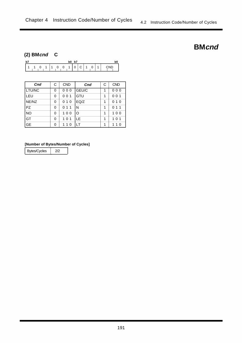
191
Chapter 4 Instruction Code/Number of Cycles 4.2 Instruction Code/Number of Cycles
GEU/C
GTU
EQ/Z
N
O
LE
LT
(2) BMcnd CBMcnd
b7 b0 b7 b0
1 1 0 1 1 0 0 1 0 C 1 0 1 CND
LTU/NC
LEU
NE/NZ
PZ
NO
GT
GE
0 0 0 0
0 0 0 1
0 0 1 0
0 0 1 1
0 1 0 0
0 1 0 1
0 1 1 0
Cnd CND Cnd CND
1 0 0 0
1 0 0 1
1 0 1 0
1 0 1 1
1 1 0 0
1 1 0 1
1 1 1 0
C C
2/2Bytes/Cycles
[Number of Bytes/Number of Cycles]
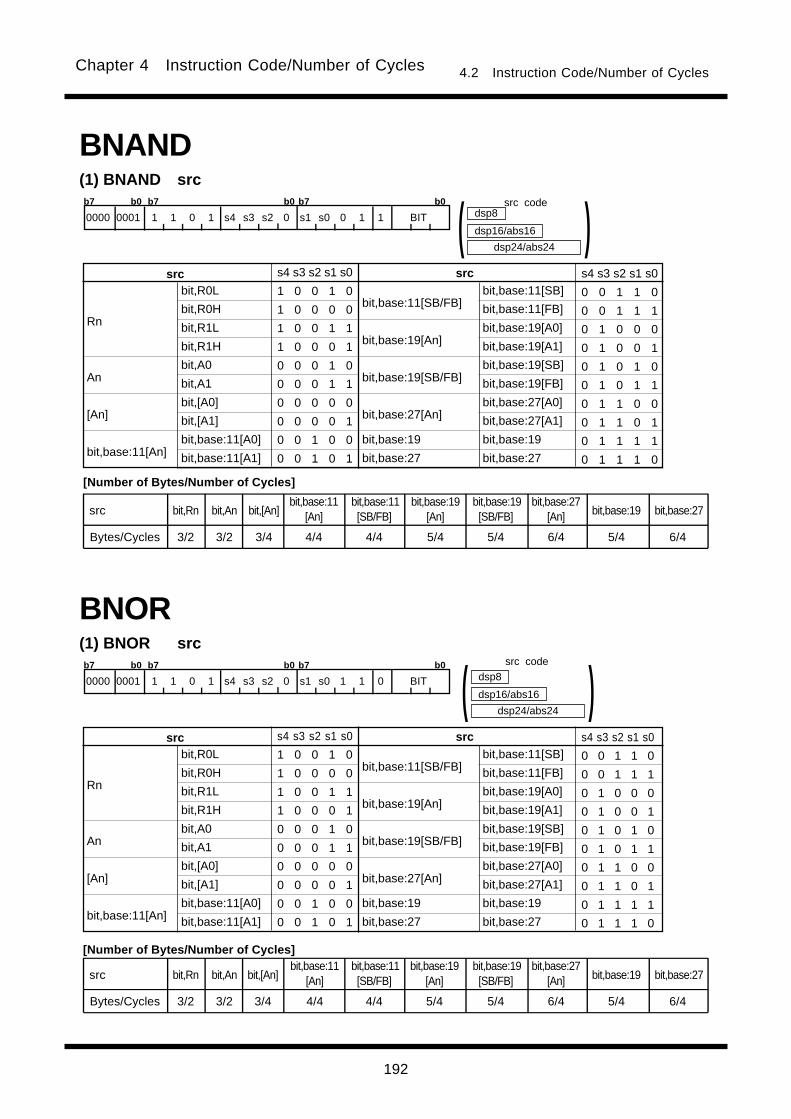
192
Chapter 4 Instruction Code/Number of Cycles 4.2 Instruction Code/Number of Cycles
(1) BNOR src
BNOR
bit,R0L
bit,R0H
bit,R1L
bit,R1H
bit,A0
bit,A1
bit,[A0]
bit,[A1]
bit,base:11[A0]
bit,base:11[A1]
bit,base:11[SB/FB]
bit,base:19[An]
bit,base:19[SB/FB]
bit,base:27[An]
bit,base:19
bit,base:27
Rn
An
[An]
bit,base:11[An]
srcsrc s4 s3 s2 s1 s0
1 0 0 1 0
1 0 0 0 0
1 0 0 1 1
1 0 0 0 1
0 0 0 1 0
0 0 0 1 1
0 0 0 0 0
0 0 0 0 1
0 0 1 0 0
0 0 1 0 1
s4 s3 s2 s1 s0
0 0 1 1 0
0 0 1 1 1
0 1 0 0 0
0 1 0 0 1
0 1 0 1 0
0 1 0 1 1
0 1 1 0 0
0 1 1 0 1
0 1 1 1 1
0 1 1 1 0
bit,base:11[SB]
bit,base:11[FB]
bit,base:19[A0]
bit,base:19[A1]
bit,base:19[SB]
bit,base:19[FB]
bit,base:27[A0]
bit,base:27[A1]
bit,base:19
bit,base:27
b7 b0 b7 b0 b7 b0
dsp24/abs24
dsp8
dsp16/abs16 )( 0000 0001 1 1 0 1 s4 s3 s2 0 s1 s0 1 1 0 BIT
(1) BNAND src
BNAND
bit,R0L
bit,R0H
bit,R1L
bit,R1H
bit,A0
bit,A1
bit,[A0]
bit,[A1]
bit,base:11[A0]
bit,base:11[A1]
bit,base:11[SB/FB]
bit,base:19[An]
bit,base:19[SB/FB]
bit,base:27[An]
bit,base:19
bit,base:27
Rn
An
[An]
bit,base:11[An]
srcsrc s4 s3 s2 s1 s0
1 0 0 1 0
1 0 0 0 0
1 0 0 1 1
1 0 0 0 1
0 0 0 1 0
0 0 0 1 1
0 0 0 0 0
0 0 0 0 1
0 0 1 0 0
0 0 1 0 1
s4 s3 s2 s1 s0
0 0 1 1 0
0 0 1 1 1
0 1 0 0 0
0 1 0 0 1
0 1 0 1 0
0 1 0 1 1
0 1 1 0 0
0 1 1 0 1
0 1 1 1 1
0 1 1 1 0
bit,base:11[SB]
bit,base:11[FB]
bit,base:19[A0]
bit,base:19[A1]
bit,base:19[SB]
bit,base:19[FB]
bit,base:27[A0]
bit,base:27[A1]
bit,base:19
bit,base:27
b7 b0 b7 b0 b7 b0
dsp24/abs24
src codedsp8
dsp16/abs16 )( 0000 0001 1 1 0 1 s4 s3 s2 0 s1 s0 0 1 1 BIT
[Number of Bytes/Number of Cycles]
bit,Rn
3/2
src
Bytes/Cycles
bit,An
3/2
bit,[An]
3/4
bit,base:11[An]
4/4
bit,base:11[SB/FB]
4/4
bit,base:19[An]
5/4
bit,base:19[SB/FB]
5/4
bit,base:27[An]
6/4
bit,base:19
5/4
bit,base:27
6/4
bit,Rn
3/2
src
Bytes/Cycles
bit,An
3/2
bit,[An]
3/4
bit,base:11[An]
4/4
bit,base:11[SB/FB]
4/4
bit,base:19[An]
5/4
bit,base:19[SB/FB]
5/4
bit,base:27[An]
6/4
bit,base:19
5/4
bit,base:27
6/4
src code
[Number of Bytes/Number of Cycles]
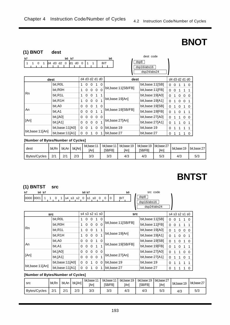
193
Chapter 4 Instruction Code/Number of Cycles 4.2 Instruction Code/Number of Cycles
(1) BNOT dest
BNOT
bit,R0L
bit,R0H
bit,R1L
bit,R1H
bit,A0
bit,A1
bit,[A0]
bit,[A1]
bit,base:11[A0]
bit,base:11[A1]
bit,base:11[SB/FB]
bit,base:19[An]
bit,base:19[SB/FB]
bit,base:27[An]
bit,base:19
bit,base:27
Rn
An
[An]
bit,base:11[An]
destdest d4 d3 d2 d1 d0
1 0 0 1 0
1 0 0 0 0
1 0 0 1 1
1 0 0 0 1
0 0 0 1 0
0 0 0 1 1
0 0 0 0 0
0 0 0 0 1
0 0 1 0 0
0 0 1 0 1
d4 d3 d2 d1 d0
0 0 1 1 0
0 0 1 1 1
0 1 0 0 0
0 1 0 0 1
0 1 0 1 0
0 1 0 1 1
0 1 1 0 0
0 1 1 0 1
0 1 1 1 1
0 1 1 1 0
bit,base:11[SB]
bit,base:11[FB]
bit,base:19[A0]
bit,base:19[A1]
bit,base:19[SB]
bit,base:19[FB]
bit,base:27[A0]
bit,base:27[A1]
bit,base:19
bit,base:27
b7 b0 b7 b0
dsp24/abs24
dsp8
dsp16/abs16 )(1 1 0 1 d4 d3 d2 0 d1 d0 0 1 1 BIT
(1) BNTST src
BNTST
bit,R0L
bit,R0H
bit,R1L
bit,R1H
bit,A0
bit,A1
bit,[A0]
bit,[A1]
bit,base:11[A0]
bit,base:11[A1]
bit,base:11[SB/FB]
bit,base:19[An]
bit,base:19[SB/FB]
bit,base:27[An]
bit,base:19
bit,base:27
Rn
An
[An]
bit,base:11[An]
srcsrc s4 s3 s2 s1 s0
1 0 0 1 0
1 0 0 0 0
1 0 0 1 1
1 0 0 0 1
0 0 0 1 0
0 0 0 1 1
0 0 0 0 0
0 0 0 0 1
0 0 1 0 0
0 0 1 0 1
s4 s3 s2 s1 s0
0 0 1 1 0
0 0 1 1 1
0 1 0 0 0
0 1 0 0 1
0 1 0 1 0
0 1 0 1 1
0 1 1 0 0
0 1 1 0 1
0 1 1 1 1
0 1 1 1 0
bit,base:11[SB]
bit,base:11[FB]
bit,base:19[A0]
bit,base:19[A1]
bit,base:19[SB]
bit,base:19[FB]
bit,base:27[A0]
bit,base:27[A1]
bit,base:19
bit,base:27
bit,Rn
2/1
src
Bytes/Cycles
bit,An
2/1
bit,[An]
2/3
bit,base:11[An]
3/3
bit,base:11[SB/FB]
3/3
bit,base:19[An]
4/3
bit,base:19[SB/FB]
4/3
bit,base:27[An]
5/3
bit,base:19
4/3
bit,base:27
5/3
bit,Rn
2/1
dest
Bytes/Cycles
bit,An
2/1
bit,[An]
2/3
bit,base:11[An]
3/3
bit,base:11[SB/FB]
3/3
bit,base:19[An]
4/3
bit,base:19[SB/FB]
4/3
bit,base:27[An]
5/3
bit,base:19
4/3
bit,base:27
5/3
b7 b0 b7 b0 b7 b0
dsp24/abs24
dsp8
dsp16/abs16 )( 0000 0001 1 1 0 1 s4 s3 s2 0 s1 s0 0 0 0 BIT
dest code
[Number of Bytes/Number of Cycles]
src code
[Number of Bytes/Number of Cycles]
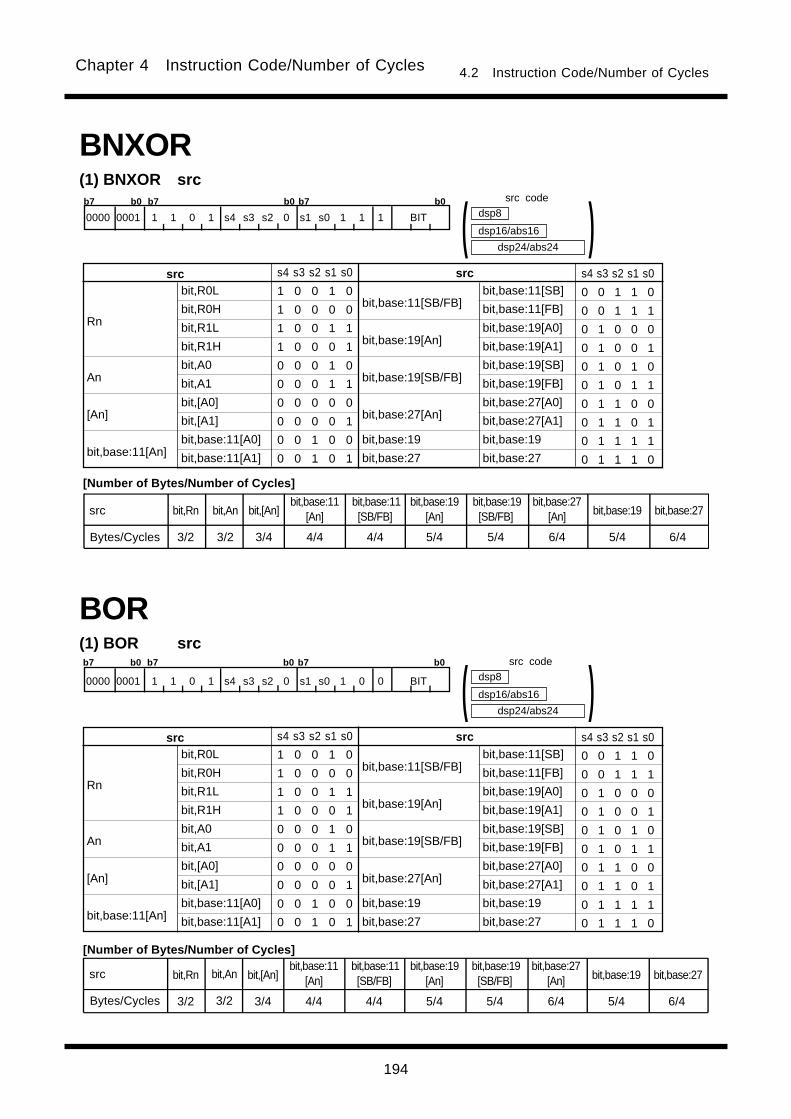
194
Chapter 4 Instruction Code/Number of Cycles 4.2 Instruction Code/Number of Cycles
(1) BOR src
BOR
bit,R0L
bit,R0H
bit,R1L
bit,R1H
bit,A0
bit,A1
bit,[A0]
bit,[A1]
bit,base:11[A0]
bit,base:11[A1]
bit,base:11[SB/FB]
bit,base:19[An]
bit,base:19[SB/FB]
bit,base:27[An]
bit,base:19
bit,base:27
Rn
An
[An]
bit,base:11[An]
srcsrc s4 s3 s2 s1 s0
1 0 0 1 0
1 0 0 0 0
1 0 0 1 1
1 0 0 0 1
0 0 0 1 0
0 0 0 1 1
0 0 0 0 0
0 0 0 0 1
0 0 1 0 0
0 0 1 0 1
s4 s3 s2 s1 s0
0 0 1 1 0
0 0 1 1 1
0 1 0 0 0
0 1 0 0 1
0 1 0 1 0
0 1 0 1 1
0 1 1 0 0
0 1 1 0 1
0 1 1 1 1
0 1 1 1 0
bit,base:11[SB]
bit,base:11[FB]
bit,base:19[A0]
bit,base:19[A1]
bit,base:19[SB]
bit,base:19[FB]
bit,base:27[A0]
bit,base:27[A1]
bit,base:19
bit,base:27
b7 b0 b7 b0 b7 b0
dsp24/abs24
dsp8
dsp16/abs16 )( 0000 0001 1 1 0 1 s4 s3 s2 0 s1 s0 1 0 0 BIT
(1) BNXOR src
BNXOR
bit,R0L
bit,R0H
bit,R1L
bit,R1H
bit,A0
bit,A1
bit,[A0]
bit,[A1]
bit,base:11[A0]
bit,base:11[A1]
bit,base:11[SB/FB]
bit,base:19[An]
bit,base:19[SB/FB]
bit,base:27[An]
bit,base:19
bit,base:27
Rn
An
[An]
bit,base:11[An]
srcsrc s4 s3 s2 s1 s0
1 0 0 1 0
1 0 0 0 0
1 0 0 1 1
1 0 0 0 1
0 0 0 1 0
0 0 0 1 1
0 0 0 0 0
0 0 0 0 1
0 0 1 0 0
0 0 1 0 1
s4 s3 s2 s1 s0
0 0 1 1 0
0 0 1 1 1
0 1 0 0 0
0 1 0 0 1
0 1 0 1 0
0 1 0 1 1
0 1 1 0 0
0 1 1 0 1
0 1 1 1 1
0 1 1 1 0
bit,base:11[SB]
bit,base:11[FB]
bit,base:19[A0]
bit,base:19[A1]
bit,base:19[SB]
bit,base:19[FB]
bit,base:27[A0]
bit,base:27[A1]
bit,base:19
bit,base:27
b7 b0 b7 b0 b7 b0
dsp24/abs24
dsp8
dsp16/abs16 )( 0000 0001 1 1 0 1 s4 s3 s2 0 s1 s0 1 1 1 BIT
bit,Rn
3/2
src
Bytes/Cycles
bit,An
3/2
bit,[An]
3/4
bit,base:11[An]
4/4
bit,base:11[SB/FB]
4/4
bit,base:19[An]
5/4
bit,base:19[SB/FB]
5/4
bit,base:27[An]
6/4
bit,base:19
5/4
bit,base:27
6/4
bit,Rn
3/2
bit,An
3/2
bit,[An]
3/4
bit,base:11[An]
4/4
bit,base:11[SB/FB]
4/4
bit,base:19[An]
5/4
bit,base:19[SB/FB]
5/4
bit,base:27[An]
6/4
bit,base:19
5/4
bit,base:27
6/4
src code
[Number of Bytes/Number of Cycles]
[Number of Bytes/Number of Cycles]
src code
src
Bytes/Cycles
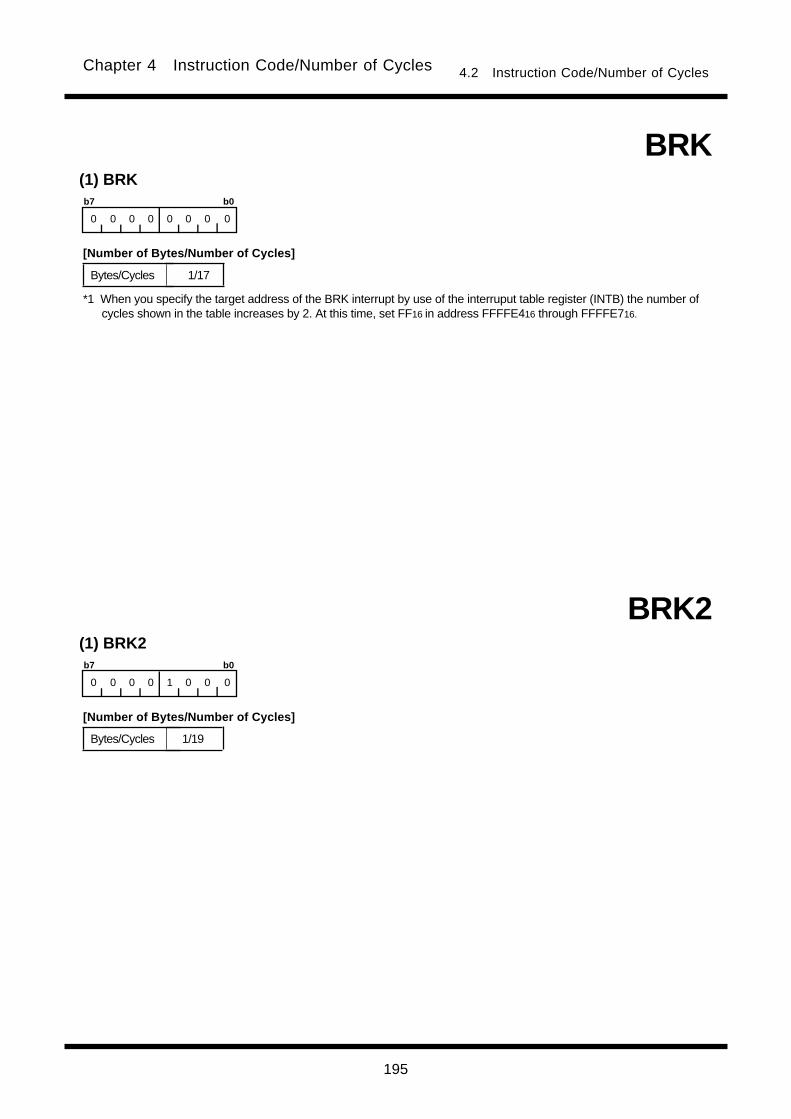
195
Chapter 4 Instruction Code/Number of Cycles 4.2 Instruction Code/Number of Cycles
BRK
1/17
(1) BRK
Bytes/Cycles
b7 b0
0 0 0 0 0 0 0 0
*1 When you specify the target address of the BRK interrupt by use of the interruput table register (INTB) the number ofcycles shown in the table increases by 2. At this time, set FF16 in address FFFFE416 through FFFFE716.
1/19
(1) BRK2
Bytes/Cycles
b7 b0
0 0 0 0 1 0 0 0
BRK2
[Number of Bytes/Number of Cycles]
[Number of Bytes/Number of Cycles]

196
Chapter 4 Instruction Code/Number of Cycles 4.2 Instruction Code/Number of Cycles
bit,base:27
5/3
(1) BTST:G src
BTST
bit,R0L
bit,R0H
bit,R1L
bit,R1H
bit,A0
bit,A1
bit,[A0]
bit,[A1]
bit,base:11[A0]
bit,base:11[A1]
bit,base:11[SB/FB]
bit,base:19[An]
bit,base:19[SB/FB]
bit,base:27[An]
bit,base:19
bit,base:27
Rn
An
[An]
bit,base:11[An]
srcsrc s4 s3 s2 s1 s0
1 0 0 1 0
1 0 0 0 0
1 0 0 1 1
1 0 0 0 1
0 0 0 1 0
0 0 0 1 1
0 0 0 0 0
0 0 0 0 1
0 0 1 0 0
0 0 1 0 1
s4 s3 s2 s1 s0
0 0 1 1 0
0 0 1 1 1
0 1 0 0 0
0 1 0 0 1
0 1 0 1 0
0 1 0 1 1
0 1 1 0 0
0 1 1 0 1
0 1 1 1 1
0 1 1 1 0
bit,base:11[SB]
bit,base:11[FB]
bit,base:19[A0]
bit,base:19[A1]
bit,base:19[SB]
bit,base:19[FB]
bit,base:27[A0]
bit,base:27[A1]
bit,base:19
bit,base:27
dsp24/abs24
dsp8
dsp16/abs16 )(b7 b0 b7 b0
1 1 0 1 s4 s3 s2 0 s1 s0 0 0 0 BIT
bit,Rn
2/1
src
Bytes/Cycles
bit,An
2/1
bit,[An]
2/3
bit,base:11[An]
3/3
bit,base:11[SB/FB]
3/3
bit,base:19[An]
4/3
bit,base:19[SB/FB]
4/3
bit,base:27[An]
5/3
bit,base:19
4/3
BSET(1) BSET dest
bit,R0L
bit,R0H
bit,R1L
bit,R1H
bit,A0
bit,A1
bit,[A0]
bit,[A1]
bit,base:11[A0]
bit,base:11[A1]
bit,base:11[SB/FB]
bit,base:19[An]
bit,base:19[SB/FB]
bit,base:27[An]
bit,base:19
bit,base:27
Rn
An
[An]
bit,base:11[An]
destdest d4 d3 d2 d1 d0
1 0 0 1 0
1 0 0 0 0
1 0 0 1 1
1 0 0 0 1
0 0 0 1 0
0 0 0 1 1
0 0 0 0 0
0 0 0 0 1
0 0 1 0 0
0 0 1 0 1
d4 d3 d2 d1 d0
0 0 1 1 0
0 0 1 1 1
0 1 0 0 0
0 1 0 0 1
0 1 0 1 0
0 1 0 1 1
0 1 1 0 0
0 1 1 0 1
0 1 1 1 1
0 1 1 1 0
bit,base:11[SB]
bit,base:11[FB]
bit,base:19[A0]
bit,base:19[A1]
bit,base:19[SB]
bit,base:19[FB]
bit,base:27[A0]
bit,base:27[A1]
bit,base:19
bit,base:27
dsp24/abs24
dsp8
dsp16/abs16 )(b7 b0 b7 b0
1 1 0 1 d4 d3 d2 0 d1 d0 1 1 1 BIT
bit,Rn
2/1
dest
Bytes/Cycles
bit,An
2/1
bit,[An]
2/3
bit,base:11[An]
3/3
bit,base:11[SB/FB]
3/3
bit,base:19[An]
4/3
bit,base:19[SB/FB]
4/3
bit,base:27[An]
5/3
bit,base:19
4/3
bit,base:27
5/3
dest code
[Number of Bytes/Number of Cycles]
src code
[Number of Bytes/Number of Cycles]

197
Chapter 4 Instruction Code/Number of Cycles 4.2 Instruction Code/Number of Cycles
BTSTC(1) BTSTC dest
bit,R0L
bit,R0H
bit,R1L
bit,R1H
bit,A0
bit,A1
bit,[A0]
bit,[A1]
bit,base:11[A0]
bit,base:11[A1]
bit,base:11[SB/FB]
bit,base:19[An]
bit,base:19[SB/FB]
bit,base:27[An]
bit,base:19
bit,base:27
Rn
An
[An]
bit,base:11[An]
destdest d4 d3 d2 d1 d0
1 0 0 1 0
1 0 0 0 0
1 0 0 1 1
1 0 0 0 1
0 0 0 1 0
0 0 0 1 1
0 0 0 0 0
0 0 0 0 1
0 0 1 0 0
0 0 1 0 1
d4 d3 d2 d1 d0
0 0 1 1 0
0 0 1 1 1
0 1 0 0 0
0 1 0 0 1
0 1 0 1 0
0 1 0 1 1
0 1 1 0 0
0 1 1 0 1
0 1 1 1 1
0 1 1 1 0
bit,base:11[SB]
bit,base:11[FB]
bit,base:19[A0]
bit,base:19[A1]
bit,base:19[SB]
bit,base:19[FB]
bit,base:27[A0]
bit,base:27[A1]
bit,base:19
bit,base:27
dsp24/abs24
dsp8
dsp16/abs16 )(b7 b0 b7 b0
1 1 0 1 d4 d3 d2 0 d1 d0 1 0 0 BIT
bit,Rn
2/2
dest
Bytes/Cycles
bit,An
2/2
bit,[An]
2/4
bit,base:11[An]
3/4
bit,base:11[SB/FB]
3/4
bit,base:19[An]
4/4
bit,base:19[SB/FB]
4/4
bit,base:27[An]
5/4
bit,base:19
4/4
bit,base:27
5/4
(2) BTST:S srcBTST
abs16
b7 b0
0 0 b2 b1 1 0 1 b0
3/3Bytes/Cycles
bit,base:19 src
src code
dest code
[Number of Bytes/Number of Cycles]
[Number of Bytes/Number of Cycles]
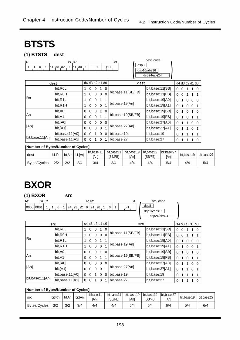
198
Chapter 4 Instruction Code/Number of Cycles 4.2 Instruction Code/Number of Cycles
(1) BXOR src
BXOR
bit,R0L
bit,R0H
bit,R1L
bit,R1H
bit,A0
bit,A1
bit,[A0]
bit,[A1]
bit,base:11[A0]
bit,base:11[A1]
bit,base:11[SB/FB]
bit,base:19[An]
bit,base:19[SB/FB]
bit,base:27[An]
bit,base:19
bit,base:27
Rn
An
[An]
bit,base:11[An]
srcsrc s4 s3 s2 s1 s0
1 0 0 1 0
1 0 0 0 0
1 0 0 1 1
1 0 0 0 1
0 0 0 1 0
0 0 0 1 1
0 0 0 0 0
0 0 0 0 1
0 0 1 0 0
0 0 1 0 1
s4 s3 s2 s1 s0
0 0 1 1 0
0 0 1 1 1
0 1 0 0 0
0 1 0 0 1
0 1 0 1 0
0 1 0 1 1
0 1 1 0 0
0 1 1 0 1
0 1 1 1 1
0 1 1 1 0
bit,base:11[SB]
bit,base:11[FB]
bit,base:19[A0]
bit,base:19[A1]
bit,base:19[SB]
bit,base:19[FB]
bit,base:27[A0]
bit,base:27[A1]
bit,base:19
bit,base:27
dsp24/abs24
dsp8
dsp16/abs16 )(
BTSTS(1) BTSTS dest
bit,R0L
bit,R0H
bit,R1L
bit,R1H
bit,A0
bit,A1
bit,[A0]
bit,[A1]
bit,base:11[A0]
bit,base:11[A1]
bit,base:11[SB/FB]
bit,base:19[An]
bit,base:19[SB/FB]
bit,base:27[An]
bit,base:19
bit,base:27
Rn
An
[An]
bit,base:11[An]
destdest d4 d3 d2 d1 d0
1 0 0 1 0
1 0 0 0 0
1 0 0 1 1
1 0 0 0 1
0 0 0 1 0
0 0 0 1 1
0 0 0 0 0
0 0 0 0 1
0 0 1 0 0
0 0 1 0 1
d4 d3 d2 d1 d0
0 0 1 1 0
0 0 1 1 1
0 1 0 0 0
0 1 0 0 1
0 1 0 1 0
0 1 0 1 1
0 1 1 0 0
0 1 1 0 1
0 1 1 1 1
0 1 1 1 0
bit,base:11[SB]
bit,base:11[FB]
bit,base:19[A0]
bit,base:19[A1]
bit,base:19[SB]
bit,base:19[FB]
bit,base:27[A0]
bit,base:27[A1]
bit,base:19
bit,base:27
dsp24/abs24
dsp8
dsp16/abs16 )(b7 b0 b7 b0
1 1 0 1 d4 d3 d2 0 d1 d0 1 0 1 BIT
b7 b0 b7 b0 b7 b0
0000 0001 1 1 0 1 s4 s3 s2 0 s1 s0 1 0 1 BIT
bit,Rn
2/2
dest
Bytes/Cycles
bit,An
2/2
bit,[An]
2/4
bit,base:11[An]
3/4
bit,base:11[SB/FB]
3/4
bit,base:19[An]
4/4
bit,base:19[SB/FB]
4/4
bit,base:27[An]
5/4
bit,base:19
4/4
bit,base:27
5/4
bit,Rn
3/2
src
Bytes/Cycles
bit,An
3/2
bit,[An]
3/4
bit,base:11[An]
4/4
bit,base:11[SB/FB]
4/4
bit,base:19[An]
5/4
bit,base:19[SB/FB]
5/4
bit,base:27[An]
6/4
bit,base:19
5/4
bit,base:27
6/4
[Number of Bytes/Number of Cycles]
dest code
src code
[Number of Bytes/Number of Cycles]
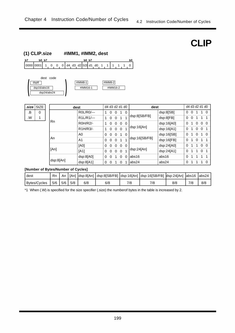
199
Chapter 4 Instruction Code/Number of Cycles 4.2 Instruction Code/Number of Cycles
(1) CLIP.size #IMM1, #IMM2, dest
#IMM8-1
#IMM16-1
dsp24/abs24
dest codedsp8
dsp16/abs16 )(
CLIP
b7 b0 b7 b0 b7 b0
0000 0001 1 0 0 0 d4 d3 d2 SIZE d1 d0 1 1 1 1 1 0
.size
.B
.W
SIZE
0
1
[Number of Bytes/Number of Cycles]
dest Rn An [An] dsp:8[An] dsp:8[SB/FB] dsp:16[An] dsp:16[SB/FB] dsp:24[An] abs16 abs24
Bytes/Cycles 5/6 5/6 5/8 6/8 6/8 7/8 7/8 8/8 7/8 8/8
R0L/R0/---
R1L/R1/---
R0H/R2/-
R1H/R3/-
A0
A1
[A0]
[A1]
dsp:8[A0]
dsp:8[A1]
dsp:8[SB/FB]
dsp:16[An]
dsp:16[SB/FB]
dsp:24[An]
abs16
abs24
Rn
An
[An]
dsp:8[An]
destdest d4 d3 d2 d1 d0
1 0 0 1 0
1 0 0 1 1
1 0 0 0 0
1 0 0 0 1
0 0 0 1 0
0 0 0 1 1
0 0 0 0 0
0 0 0 0 1
0 0 1 0 0
0 0 1 0 1
d4 d3 d2 d1 d0
0 0 1 1 0
0 0 1 1 1
0 1 0 0 0
0 1 0 0 1
0 1 0 1 0
0 1 0 1 1
0 1 1 0 0
0 1 1 0 1
0 1 1 1 1
0 1 1 1 0
dsp:8[SB]
dsp:8[FB]
dsp:16[A0]
dsp:16[A1]
dsp:16[SB]
dsp:16[FB]
dsp:24[A0]
dsp:24[A1]
abs16
abs24
#IMM8-2
#IMM16-2
*1 When (.W) is specified for the size specifier (.size) the numberof bytes in the table is increased by 2.
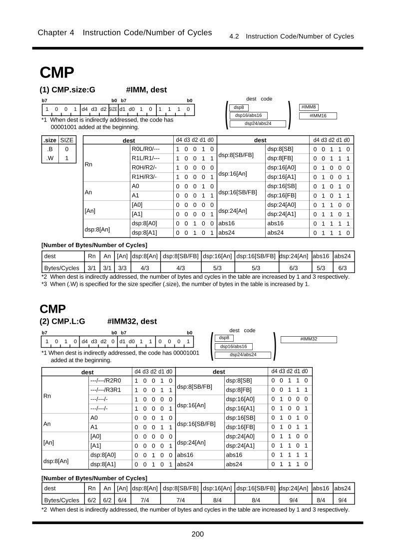
200
Chapter 4 Instruction Code/Number of Cycles 4.2 Instruction Code/Number of Cycles
(2) CMP.L:G #IMM32, destb7 b0 b7 b0
1 0 1 0 d4 d3 d2 0 d1 d0 1 1 0 0 0 1
---/---/R2R0
---/---/R3R1
---/---/-
---/---/-
A0
A1
[A0]
[A1]
dsp:8[A0]
dsp:8[A1]
dsp:8[SB/FB]
dsp:16[An]
dsp:16[SB/FB]
dsp:24[An]
abs16
abs24
Rn
An
[An]
dsp:8[An]
destdest d4 d3 d2 d1 d0
1 0 0 1 0
1 0 0 1 1
1 0 0 0 0
1 0 0 0 1
0 0 0 1 0
0 0 0 1 1
0 0 0 0 0
0 0 0 0 1
0 0 1 0 0
0 0 1 0 1
d4 d3 d2 d1 d0
0 0 1 1 0
0 0 1 1 1
0 1 0 0 0
0 1 0 0 1
0 1 0 1 0
0 1 0 1 1
0 1 1 0 0
0 1 1 0 1
0 1 1 1 1
0 1 1 1 0
dsp24/abs24
dsp8
dsp16/abs16 )(dsp:8[SB]
dsp:8[FB]
dsp:16[A0]
dsp:16[A1]
dsp:16[SB]
dsp:16[FB]
dsp:24[A0]
dsp:24[A1]
abs16
abs24
CMP
#IMM32
dest Rn An [An] dsp:8[An] dsp:8[SB/FB] dsp:16[An] dsp:16[SB/FB] dsp:24[An] abs16 abs24
Bytes/Cycles 6/2 6/2 6/4 7/4 7/4 8/4 8/4 9/4 8/4 9/4
b7 b0 b7 b0
1 0 0 1 d4 d3 d2 SIZE d1 d0 1 0 1 1 1 0
CMP(1) CMP.size:G #IMM, dest
.size
.B
.W
SIZE
0
1
dest Rn An [An] dsp:8[An] dsp:8[SB/FB] dsp:16[An] dsp:16[SB/FB] dsp:24[An] abs16 abs24
Bytes/Cycles 3/1 3/1 3/3 4/3 4/3 5/3 5/3 6/3 5/3 6/3
R0L/R0/---
R1L/R1/---
R0H/R2/-
R1H/R3/-
A0
A1
[A0]
[A1]
dsp:8[A0]
dsp:8[A1]
dsp:8[SB/FB]
dsp:16[An]
dsp:16[SB/FB]
dsp:24[An]
abs16
abs24
Rn
An
[An]
dsp:8[An]
destdest d4 d3 d2 d1 d0
1 0 0 1 0
1 0 0 1 1
1 0 0 0 0
1 0 0 0 1
0 0 0 1 0
0 0 0 1 1
0 0 0 0 0
0 0 0 0 1
0 0 1 0 0
0 0 1 0 1
d4 d3 d2 d1 d0
0 0 1 1 0
0 0 1 1 1
0 1 0 0 0
0 1 0 0 1
0 1 0 1 0
0 1 0 1 1
0 1 1 0 0
0 1 1 0 1
0 1 1 1 1
0 1 1 1 0
dsp24/abs24
dsp8
dsp16/abs16 )(dsp:8[SB]
dsp:8[FB]
dsp:16[A0]
dsp:16[A1]
dsp:16[SB]
dsp:16[FB]
dsp:24[A0]
dsp:24[A1]
abs16
abs24
#IMM8
#IMM16
dest code
[Number of Bytes/Number of Cycles]
*1 When dest is indirectly addressed, the code has00001001 added at the beginning.
*2 When dest is indirectly addressed, the number of bytes and cycles in the table are increased by 1 and 3 respectively.*3 When (.W) is specified for the size specifier (.size), the number of bytes in the table is increased by 1.
dest code
*1 When dest is indirectly addressed, the code has 00001001added at the beginning.
[Number of Bytes/Number of Cycles]
*2 When dest is indirectly addressed, the number of bytes and cycles in the table are increased by 1 and 3 respectively.

201
Chapter 4 Instruction Code/Number of Cycles 4.2 Instruction Code/Number of Cycles
b7 b0 b7 b0
1 1 1 0 d4 d3 d2 SIZE d1 d0 0 1 IMM4
dest Rn An [An] dsp:8[An] dsp:8[SB/FB] dsp:16[An] dsp:16[SB/FB] dsp:24[An] abs16 abs24
Bytes/Cycles 2/1 2/1 2/3 3/3 3/3 4/3 4/3 5/3 4/3 5/3
0
+1
+2
+3
+4
+5
+6
+7
#IMM#IMM IMM4
0 0 0 0
0 0 0 1
0 0 1 0
0 0 1 1
0 1 0 0
0 1 0 1
0 1 1 0
0 1 1 1
IMM4
1 0 0 0
1 0 0 1
1 0 1 0
1 0 1 1
1 1 0 0
1 1 0 1
1 1 1 0
1 1 1 1
dsp24/abs24
dsp8
dsp16/abs16 )(CMP
R0L/R0/---
R1L/R1/---
R0H/R2/-
R1H/R3/-
A0
A1
[A0]
[A1]
dsp:8[A0]
dsp:8[A1]
dsp:8[SB/FB]
dsp:16[An]
dsp:16[SB/FB]
dsp:24[An]
abs16
abs24
Rn
An
[An]
dsp:8[An]
destdest d4 d3 d2 d1 d0
1 0 0 1 0
1 0 0 1 1
1 0 0 0 0
1 0 0 0 1
0 0 0 1 0
0 0 0 1 1
0 0 0 0 0
0 0 0 0 1
0 0 1 0 0
0 0 1 0 1
d4 d3 d2 d1 d0
0 0 1 1 0
0 0 1 1 1
0 1 0 0 0
0 1 0 0 1
0 1 0 1 0
0 1 0 1 1
0 1 1 0 0
0 1 1 0 1
0 1 1 1 1
0 1 1 1 0
dsp:8[SB]
dsp:8[FB]
dsp:16[A0]
dsp:16[A1]
dsp:16[SB]
dsp:16[FB]
dsp:24[A0]
dsp:24[A1]
abs16
abs24
-8
-7
-6
-5
-4
-3
-2
-1
.size
.B
.W
SIZE
0
1
dest code
*1 When dest is indirectly addressed, the code has00001001 added at the beginning.
[Number of Bytes/Number of Cycles]
*2 When dest is indirectly addressed, the number of bytes and cycles in the table are increased by 1 and 3 respectively.
(3) CMP.size:Q #IMM, dest

202
Chapter 4 Instruction Code/Number of Cycles 4.2 Instruction Code/Number of Cycles
dest Rn dsp:8[SB/FB] abs16
Bytes/Cycles 2/1 3/3 4/3
(4) CMP.size:S #IMM, dest
.size
.B
.W
SIZE
0
1
b7 b0
0 1 d1 d0 0 1 1 SIZE
R0L/R0
dsp:8[SB]
dsp:8[FB]
abs16
Rn
dsp:8[SB/FB]
abs16
dest d1 d0
0 0
1 0
1 1
0 1
#IMM8
#IMM16
dsp8
abs16 )(CMP
dest code
*1 When dest is indirectly addressed, the code has00001001 added at the beginning.
[Number of Bytes/Number of Cycles]
*2 When dest is indirectly addressed, the number of bytes and cycles in the table are increased by 1 and 3 respectively.*3 When (.W) is specified for the size specifier (.size), the number of bytes in the table is increased by 1.

203
Chapter 4 Instruction Code/Number of Cycles 4.2 Instruction Code/Number of Cycles
src dest Rn An [An] dsp:8[An] dsp:8[SB/FB] dsp:16[An] dsp:16[SB/FB] dsp:24[An] abs16 abs24
Rn 2/1 2/1 2/3 3/3 3/3 4/3 4/3 5/3 4/3 5/3
An 2/1 2/1 2/3 3/3 3/3 4/3 4/3 5/3 4/3 5/3
[An] 2/3 2/3 2/4 3/4 3/4 4/4 4/4 5/4 4/4 5/4
dsp:8[An] 3/3 3/3 3/4 4/4 4/4 5/4 5/4 6/4 5/4 6/4
dsp:8[SB/FB] 3/3 3/3 3/4 4/4 4/4 5/4 5/4 6/4 5/4 6/4
dsp:16[An] 4/3 4/3 4/4 5/4 5/4 6/4 6/4 7/4 6/4 7/4
dsp:16[SB/FB] 4/3 4/3 4/4 5/4 5/4 6/4 6/4 7/4 6/4 7/4
dsp:24[An] 5/3 5/3 5/4 6/4 6/4 7/4 7/4 8/4 7/4 8/4
abs16 4/3 4/3 4/4 5/4 5/4 6/4 6/4 7/4 6/4 7/4
abs24 5/3 5/3 5/4 6/4 6/4 7/4 7/4 8/4 7/4 8/4
(5) CMP.size:G src, destb7 b0 b7 b0
1 s4 s3 s2 d4 d3 d2 SIZE d1 d0 s1 s0 0 1 1 0
R0L/R0/---
R1L/R1/---
R0H/R2/-
R1H/R3/-
A0
A1
[A0]
[A1]
dsp:8[A0]
dsp:8[A1]
dsp:8[SB/FB]
dsp:16[An]
dsp:16[SB/FB]
dsp:24[An]
abs16
abs24
Rn
An
[An]
dsp:8[An]
src/destsrc/dest s4 s3 s2 s1 s0d4 d3 d2 d1 d0
1 0 0 1 0
1 0 0 1 1
1 0 0 0 0
1 0 0 0 1
0 0 0 1 0
0 0 0 1 1
0 0 0 0 0
0 0 0 0 1
0 0 1 0 0
0 0 1 0 1
s4 s3 s2 s1 s0d4 d3 d2 d1 d0
0 0 1 1 0
0 0 1 1 1
0 1 0 0 0
0 1 0 0 1
0 1 0 1 0
0 1 0 1 1
0 1 1 0 0
0 1 1 0 1
0 1 1 1 1
0 1 1 1 0
dsp24/abs24
dsp8
dsp16/abs16 )(
dsp:8[SB]
dsp:8[FB]
dsp:16[A0]
dsp:16[A1]
dsp:16[SB]
dsp:16[FB]
dsp:24[A0]
dsp:24[A1]
abs16
abs24
dsp24/abs24
dsp8
dsp16/abs16 )(CMP
.size
.B
.W
SIZE
0
1
dest codesrc code
*1 For indirect addressing, the following number is added atthe beginning of code:
01000001 when src is indirectly addressed00001001 when dest is indirectly addressed01001001 when src and dest are indirectly addressed
[Number of Bytes/Number of Cycles]
*2 When src or dest is indirectly addressed, the number of bytes and cycles in the table are increased by 1 and 3respectively. Also, when src and dest both are indirectly addressed, the number of bytes and cycles in the table areincreased by 1 and 6, respectively.

204
Chapter 4 Instruction Code/Number of Cycles 4.2 Instruction Code/Number of Cycles
1 s4 s3 s2 d4 d3 d2 1 d1 d0 s1 s0 0 0 0 1
src dest Rn An [An] dsp:8[An] dsp:8[SB/FB] dsp:16[An] dsp:16[SB/FB] dsp:24[An] abs16 abs24
Rn 2/2 2/2 2/5 3/5 3/5 4/5 4/5 5/5 4/5 5/5
An 2/2 2/2 2/5 3/5 3/5 4/5 4/5 5/5 4/5 5/5
[An] 2/5 2/5 2/8 3/8 3/8 4/8 4/8 5/8 4/8 5/8
dsp:8[An] 3/5 3/5 3/8 4/8 4/8 5/8 5/8 6/8 5/8 6/8
dsp:8[SB/FB] 3/5 3/5 3/8 4/8 4/8 5/8 5/8 6/8 5/8 6/8
dsp:16[An] 4/5 4/5 4/8 5/8 5/8 6/8 6/8 7/8 6/8 7/8
dsp:16[SB/FB] 4/5 4/5 4/8 5/8 5/8 6/8 6/8 7/8 6/8 7/8
dsp:24[An] 5/5 5/5 5/8 6/8 6/8 7/8 7/8 8/8 7/8 8/8
abs16 4/5 4/5 4/8 5/8 5/8 6/8 6/8 7/8 6/8 7/8
abs24 5/5 5/5 5/8 6/8 6/8 7/8 7/8 8/8 7/8 8/8
(6) CMP.L:G src, destb7 b0 b7 b0
---/---/R2R0
---/---/R3R1
---/---/-
---/---/-
A0
A1
[A0]
[A1]
dsp:8[A0]
dsp:8[A1]
dsp:8[SB/FB]
dsp:16[An]
dsp:16[SB/FB]
dsp:24[An]
abs16
abs24
Rn
An
[An]
dsp:8[An]
src/destsrc/dest s4 s3 s2 s1 s0d4 d3 d2 d1 d0
1 0 0 1 0
1 0 0 1 1
1 0 0 0 0
1 0 0 0 1
0 0 0 1 0
0 0 0 1 1
0 0 0 0 0
0 0 0 0 1
0 0 1 0 0
0 0 1 0 1
s4 s3 s2 s1 s0d4 d3 d2 d1 d0
0 0 1 1 0
0 0 1 1 1
0 1 0 0 0
0 1 0 0 1
0 1 0 1 0
0 1 0 1 1
0 1 1 0 0
0 1 1 0 1
0 1 1 1 1
0 1 1 1 0
dsp24/abs24
dsp8
dsp16/abs16 )(
dsp:8[SB]
dsp:8[FB]
dsp:16[A0]
dsp:16[A1]
dsp:16[SB]
dsp:16[FB]
dsp:24[A0]
dsp:24[A1]
abs16
abs24
dsp24/abs24
dsp8
dsp16/abs16 )(CMP
dest codesrc code
*1 For indirect addressing, the following number is added atthe beginning of code:
01000001 when src is indirectly addressed00001001 when dest is indirectly addressed01001001 when src and dest are indirectly addressed
[Number of Bytes/Number of Cycles]
*2 When src or dest is indirectly addressed, the number of bytes and cycles in the table are increased by 1 and 3respectively. Also, when src and dest both are indirectly addressed, the number of bytes and cycles in the table areincreased by 1 and 6, respectively.
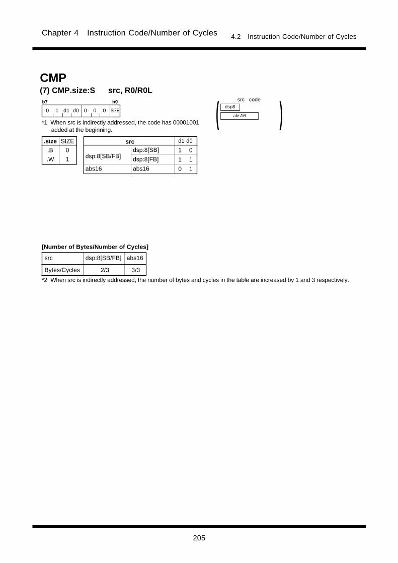
205
Chapter 4 Instruction Code/Number of Cycles 4.2 Instruction Code/Number of Cycles
src dsp:8[SB/FB] abs16
Bytes/Cycles 2/3 3/3
(7) CMP.size:S src, R0/R0L
.size
.B
.W
SIZE
0
1
b7 b0
0 1 d1 d0 0 0 0 SIZE
dsp:8[SB]
dsp:8[FB]
abs16
dsp:8[SB/FB]
abs16
src d1 d0
1 0
1 1
0 1
dsp8
abs16 )(CMP
*1 When src is indirectly addressed, the code has 00001001added at the beginning.
src code
[Number of Bytes/Number of Cycles]
*2 When src is indirectly addressed, the number of bytes and cycles in the table are increased by 1 and 3 respectively.
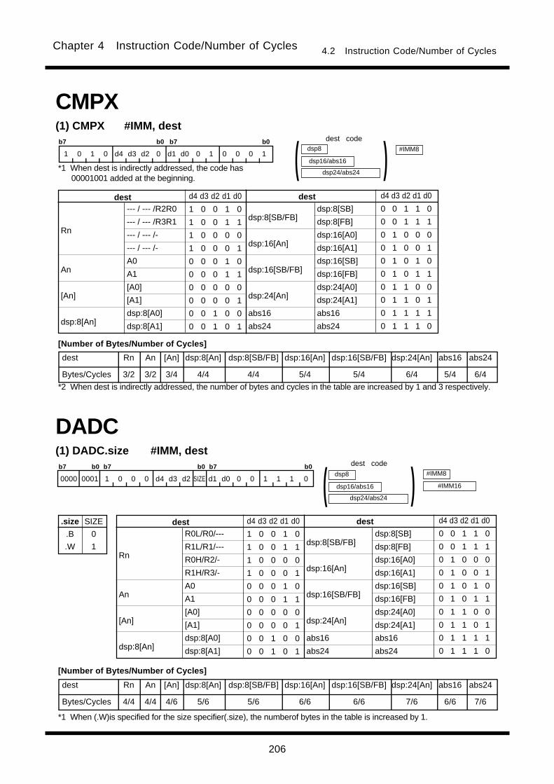
206
Chapter 4 Instruction Code/Number of Cycles 4.2 Instruction Code/Number of Cycles
(1) DADC.size #IMM, dest
.size
.B
.W
SIZE
0
1
R0L/R0/---
R1L/R1/---
R0H/R2/-
R1H/R3/-
A0
A1
[A0]
[A1]
dsp:8[A0]
dsp:8[A1]
dsp:8[SB/FB]
dsp:16[An]
dsp:16[SB/FB]
dsp:24[An]
abs16
abs24
Rn
An
[An]
dsp:8[An]
destdest d4 d3 d2 d1 d0
1 0 0 1 0
1 0 0 1 1
1 0 0 0 0
1 0 0 0 1
0 0 0 1 0
0 0 0 1 1
0 0 0 0 0
0 0 0 0 1
0 0 1 0 0
0 0 1 0 1
d4 d3 d2 d1 d0
0 0 1 1 0
0 0 1 1 1
0 1 0 0 0
0 1 0 0 1
0 1 0 1 0
0 1 0 1 1
0 1 1 0 0
0 1 1 0 1
0 1 1 1 1
0 1 1 1 0
dsp24/abs24
dsp8
dsp16/abs16 )(dsp:8[SB]
dsp:8[FB]
dsp:16[A0]
dsp:16[A1]
dsp:16[SB]
dsp:16[FB]
dsp:24[A0]
dsp:24[A1]
abs16
abs24
#IMM8
#IMM16
DADC
b7 b0 b7 b0 b7 b0
0000 0001 1 0 0 0 d4 d3 d2 SIZE d1 d0 0 0 1 1 1 0
(1) CMPX #IMM, destb7 b0 b7 b0
1 0 1 0 d4 d3 d2 0 d1 d0 0 1 0 0 0 1
--- / --- /R2R0
--- / --- /R3R1
--- / --- /-
--- / --- /-
A0
A1
[A0]
[A1]
dsp:8[A0]
dsp:8[A1]
dsp:8[SB/FB]
dsp:16[An]
dsp:16[SB/FB]
dsp:24[An]
abs16
abs24
Rn
An
[An]
dsp:8[An]
destdest d4 d3 d2 d1 d0
1 0 0 1 0
1 0 0 1 1
1 0 0 0 0
1 0 0 0 1
0 0 0 1 0
0 0 0 1 1
0 0 0 0 0
0 0 0 0 1
0 0 1 0 0
0 0 1 0 1
d4 d3 d2 d1 d0
0 0 1 1 0
0 0 1 1 1
0 1 0 0 0
0 1 0 0 1
0 1 0 1 0
0 1 0 1 1
0 1 1 0 0
0 1 1 0 1
0 1 1 1 1
0 1 1 1 0
dsp24/abs24
dsp8
dsp16/abs16 )(dsp:8[SB]
dsp:8[FB]
dsp:16[A0]
dsp:16[A1]
dsp:16[SB]
dsp:16[FB]
dsp:24[A0]
dsp:24[A1]
abs16
abs24
CMPX
#IMM8
dest Rn An [An] dsp:8[An] dsp:8[SB/FB] dsp:16[An] dsp:16[SB/FB] dsp:24[An] abs16 abs24
Bytes/Cycles 3/2 3/2 3/4 4/4 4/4 5/4 5/4 6/4 5/4 6/4
dest Rn An [An] dsp:8[An] dsp:8[SB/FB] dsp:16[An] dsp:16[SB/FB] dsp:24[An] abs16 abs24
Bytes/Cycles 4/4 4/4 4/6 5/6 5/6 6/6 6/6 7/6 6/6 7/6
dest code
*1 When dest is indirectly addressed, the code has00001001 added at the beginning.
[Number of Bytes/Number of Cycles]
*2 When dest is indirectly addressed, the number of bytes and cycles in the table are increased by 1 and 3 respectively.
dest code
[Number of Bytes/Number of Cycles]
*1 When (.W)is specified for the size specifier(.size), the numberof bytes in the table is increased by 1.

207
Chapter 4 Instruction Code/Number of Cycles 4.2 Instruction Code/Number of Cycles
src dest Rn An [An] dsp:8[An] dsp:8[SB/FB] dsp:16[An] dsp:16[SB/FB] dsp:24[An] abs16 abs24
Rn 3/4 3/4 3/6 4/6 4/6 5/6 5/6 6/6 5/6 6/6
An 3/4 3/4 3/6 4/6 4/6 5/6 5/6 6/6 5/6 6/6
[An] 3/6 3/6 3/7 4/7 4/7 5/7 5/7 6/7 5/7 6/7
dsp:8[An] 4/6 4/6 4/7 5/7 5/7 6/7 6/7 7/7 6/7 7/7
dsp:8[SB/FB] 4/6 4/6 4/7 5/7 5/7 6/7 6/7 7/7 6/7 7/7
dsp:16[An] 5/6 5/6 5/7 6/7 6/7 7/7 7/7 8/7 7/7 8/7
dsp:16[SB/FB] 5/6 5/6 5/7 6/7 6/7 7/7 7/7 8/7 7/7 8/7
dsp:24[An] 6/6 6/6 6/7 7/7 7/7 8/7 8/7 9/7 8/7 9/7
abs16 5/6 5/6 5/7 6/7 6/7 7/7 7/7 8/7 7/7 8/7
abs24 6/6 6/6 6/7 7/7 7/7 8/7 8/7 9/7 8/7 9/7
(2) DADC.size src, dest
dsp24/abs24
dsp8
dsp16/abs16 )( dsp24/abs24
dsp8
dsp16/abs16 )(DADC
b7 b0 b7 b0 b7 b0
0000 0001 1 s4 s3 s2 d4 d3 d2 SIZE d1 d0 s1 s0 1 0 0 0
.size
.B
.W
SIZE
0
1 R0L/R0/---
R1L/R1/---
R0H/R2/-
R1H/R3/-
A0
A1
[A0]
[A1]
dsp:8[A0]
dsp:8[A1]
dsp:8[SB/FB]
dsp:16[An]
dsp:16[SB/FB]
dsp:24[An]
abs16
abs24
Rn
An
[An]
dsp:8[An]
src/destsrc/dest s4 s3 s2 s1 s0d4 d3 d2 d1 d0
1 0 0 1 0
1 0 0 1 1
1 0 0 0 0
1 0 0 0 1
0 0 0 1 0
0 0 0 1 1
0 0 0 0 0
0 0 0 0 1
0 0 1 0 0
0 0 1 0 1
s4 s3 s2 s1 s0d4 d3 d2 d1 d0
0 0 1 1 0
0 0 1 1 1
0 1 0 0 0
0 1 0 0 1
0 1 0 1 0
0 1 0 1 1
0 1 1 0 0
0 1 1 0 1
0 1 1 1 1
0 1 1 1 0
dsp:8[SB]
dsp:8[FB]
dsp:16[A0]
dsp:16[A1]
dsp:16[SB]
dsp:16[FB]
dsp:24[A0]
dsp:24[A1]
abs16
abs24
src code dest code
[Number of Bytes/Number of Cycles]
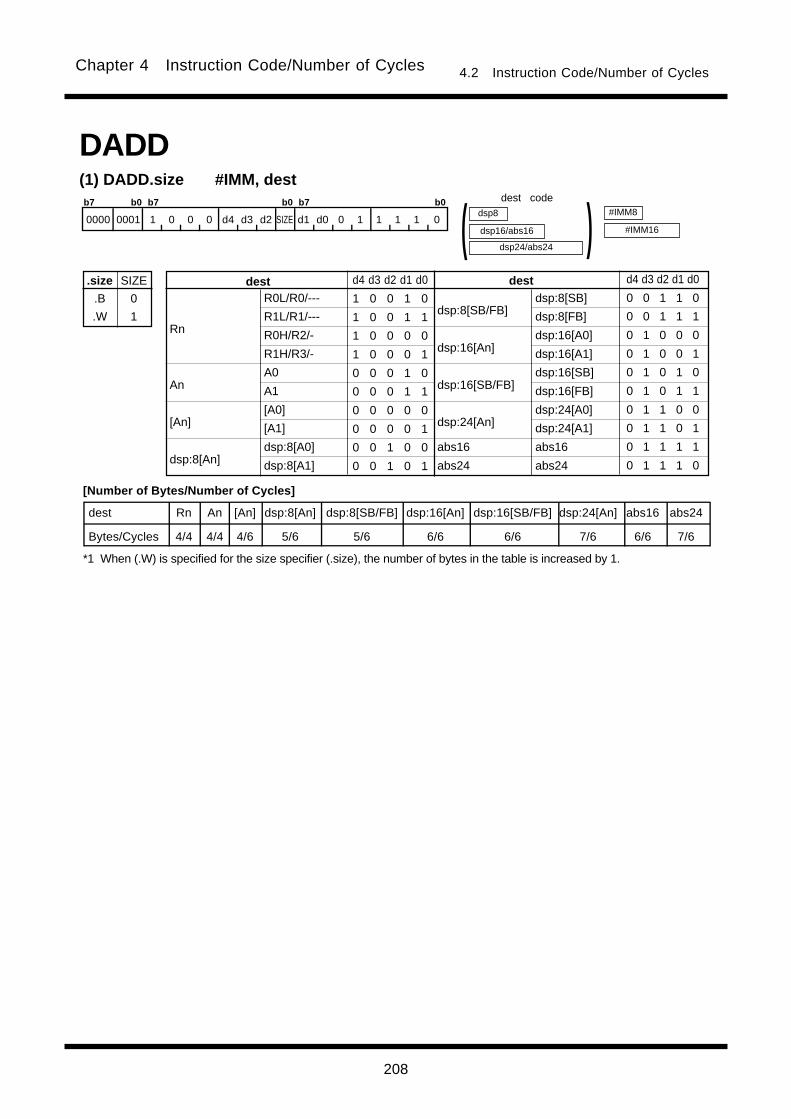
208
Chapter 4 Instruction Code/Number of Cycles 4.2 Instruction Code/Number of Cycles
(1) DADD.size #IMM, dest
.size
.B
.W
SIZE
0
1
dest Rn An [An] dsp:8[An] dsp:8[SB/FB] dsp:16[An] dsp:16[SB/FB] dsp:24[An] abs16 abs24
Bytes/Cycles 4/4 4/4 4/6 5/6 5/6 6/6 6/6 7/6 6/6 7/6
R0L/R0/---
R1L/R1/---
R0H/R2/-
R1H/R3/-
A0
A1
[A0]
[A1]
dsp:8[A0]
dsp:8[A1]
dsp:8[SB/FB]
dsp:16[An]
dsp:16[SB/FB]
dsp:24[An]
abs16
abs24
Rn
An
[An]
dsp:8[An]
destdest d4 d3 d2 d1 d0
1 0 0 1 0
1 0 0 1 1
1 0 0 0 0
1 0 0 0 1
0 0 0 1 0
0 0 0 1 1
0 0 0 0 0
0 0 0 0 1
0 0 1 0 0
0 0 1 0 1
d4 d3 d2 d1 d0
0 0 1 1 0
0 0 1 1 1
0 1 0 0 0
0 1 0 0 1
0 1 0 1 0
0 1 0 1 1
0 1 1 0 0
0 1 1 0 1
0 1 1 1 1
0 1 1 1 0
dsp24/abs24
dsp8
dsp16/abs16 )(dsp:8[SB]
dsp:8[FB]
dsp:16[A0]
dsp:16[A1]
dsp:16[SB]
dsp:16[FB]
dsp:24[A0]
dsp:24[A1]
abs16
abs24
#IMM8
#IMM16
b7 b0 b7 b0 b7 b0
0000 0001 1 0 0 0 d4 d3 d2 SIZE d1 d0 0 1 1 1 1 0
DADDdest code
[Number of Bytes/Number of Cycles]
*1 When (.W) is specified for the size specifier (.size), the number of bytes in the table is increased by 1.
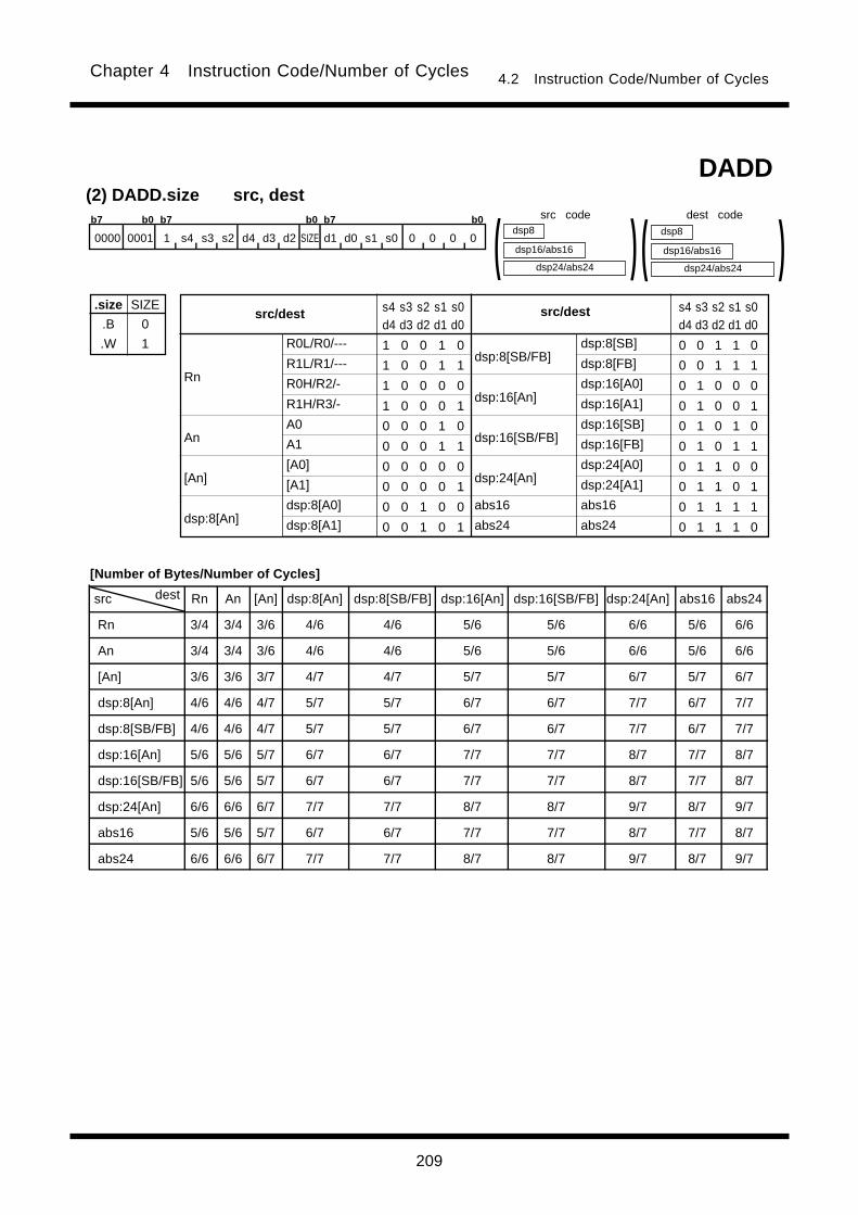
209
Chapter 4 Instruction Code/Number of Cycles 4.2 Instruction Code/Number of Cycles
DADD
src dest Rn An [An] dsp:8[An] dsp:8[SB/FB] dsp:16[An] dsp:16[SB/FB] dsp:24[An] abs16 abs24
Rn 3/4 3/4 3/6 4/6 4/6 5/6 5/6 6/6 5/6 6/6
An 3/4 3/4 3/6 4/6 4/6 5/6 5/6 6/6 5/6 6/6
[An] 3/6 3/6 3/7 4/7 4/7 5/7 5/7 6/7 5/7 6/7
dsp:8[An] 4/6 4/6 4/7 5/7 5/7 6/7 6/7 7/7 6/7 7/7
dsp:8[SB/FB] 4/6 4/6 4/7 5/7 5/7 6/7 6/7 7/7 6/7 7/7
dsp:16[An] 5/6 5/6 5/7 6/7 6/7 7/7 7/7 8/7 7/7 8/7
dsp:16[SB/FB] 5/6 5/6 5/7 6/7 6/7 7/7 7/7 8/7 7/7 8/7
dsp:24[An] 6/6 6/6 6/7 7/7 7/7 8/7 8/7 9/7 8/7 9/7
abs16 5/6 5/6 5/7 6/7 6/7 7/7 7/7 8/7 7/7 8/7
abs24 6/6 6/6 6/7 7/7 7/7 8/7 8/7 9/7 8/7 9/7
(2) DADD.size src, dest
dsp24/abs24
dsp8
dsp16/abs16 )( dsp24/abs24
dsp8
dsp16/abs16 )(b7 b0 b7 b0 b7 b0
0000 0001 1 s4 s3 s2 d4 d3 d2 SIZE d1 d0 s1 s0 0 0 0 0
.size
.B
.W
SIZE
0
1 R0L/R0/---
R1L/R1/---
R0H/R2/-
R1H/R3/-
A0
A1
[A0]
[A1]
dsp:8[A0]
dsp:8[A1]
dsp:8[SB/FB]
dsp:16[An]
dsp:16[SB/FB]
dsp:24[An]
abs16
abs24
Rn
An
[An]
dsp:8[An]
src/destsrc/dest s4 s3 s2 s1 s0d4 d3 d2 d1 d0
1 0 0 1 0
1 0 0 1 1
1 0 0 0 0
1 0 0 0 1
0 0 0 1 0
0 0 0 1 1
0 0 0 0 0
0 0 0 0 1
0 0 1 0 0
0 0 1 0 1
s4 s3 s2 s1 s0d4 d3 d2 d1 d0
0 0 1 1 0
0 0 1 1 1
0 1 0 0 0
0 1 0 0 1
0 1 0 1 0
0 1 0 1 1
0 1 1 0 0
0 1 1 0 1
0 1 1 1 1
0 1 1 1 0
dsp:8[SB]
dsp:8[FB]
dsp:16[A0]
dsp:16[A1]
dsp:16[SB]
dsp:16[FB]
dsp:24[A0]
dsp:24[A1]
abs16
abs24
dest codesrc code
[Number of Bytes/Number of Cycles]

210
Chapter 4 Instruction Code/Number of Cycles 4.2 Instruction Code/Number of Cycles
Bytes/Cycles 3/18
(1) DIV.size #IMM
.size
.B
.W
SIZE
0
1
#IMM8
#IMM16
DIV
b7 b0 b7 b0
1 0 1 1 0 0 0 0 0 1 0 SIZE 0 0 1 1
(1) DEC.size dest
.size
.B
.W
SIZE
0
1
b7 b0 b7 b0
1 0 1 1 d4 d3 d2 SIZE d1 d0 0 0 1 1 1 0
dest Rn An [An] dsp:8[An] dsp:8[SB/FB] dsp:16[An] dsp:16[SB/FB] dsp:24[An] abs16 abs24
Bytes/Cycles 2/1 2/1 2/3 3/3 3/3 4/3 4/3 5/3 4/3 5/3
dsp24/abs24
dsp8
dsp16/abs16 )(DEC
R0L/R0/---
R1L/R1/---
R0H/R2/-
R1H/R3/-
A0
A1
[A0]
[A1]
dsp:8[A0]
dsp:8[A1]
dsp:8[SB/FB]
dsp:16[An]
dsp:16[SB/FB]
dsp:24[An]
abs16
abs24
Rn
An
[An]
dsp:8[An]
destdest d4 d3 d2 d1 d0
1 0 0 1 0
1 0 0 1 1
1 0 0 0 0
1 0 0 0 1
0 0 0 1 0
0 0 0 1 1
0 0 0 0 0
0 0 0 0 1
0 0 1 0 0
0 0 1 0 1
d4 d3 d2 d1 d0
0 0 1 1 0
0 0 1 1 1
0 1 0 0 0
0 1 0 0 1
0 1 0 1 0
0 1 0 1 1
0 1 1 0 0
0 1 1 0 1
0 1 1 1 1
0 1 1 1 0
dsp:8[SB]
dsp:8[FB]
dsp:16[A0]
dsp:16[A1]
dsp:16[SB]
dsp:16[FB]
dsp:24[A0]
dsp:24[A1]
abs16
abs24
dest code
*1 When dest is indirectly addressed,the code has00001001 added at the beginning.
[Number of Bytes/Number of Cycles]
*2 When dest is indirectly addressed, the number of bytes and cycles in the table are increased by 1 and 3 respectively.
[Number of Bytes/Number of Cycles]
*1 When (.W) is specified for the size specifier (.size), the number of bytes and cycles in the table are increased by 1 and6, respectively.

211
Chapter 4 Instruction Code/Number of Cycles 4.2 Instruction Code/Number of Cycles
src Rn An [An] dsp:8[An] dsp:8[SB/FB] dsp:16[An] dsp:16[SB/FB] dsp:24[An] abs16 abs24
Bytes/Cycles 2/18 2/18 2/20 3/20 3/20 4/20 4/20 5/20 4/20 5/20
(2) DIV.size src
.size
.B
.W
SIZE
0
1
b7 b0 b7 b0
1 0 0 0 s4 s3 s2 SIZE s1 s0 0 1 1 1 1 0
dsp24/abs24
dsp8
dsp16/abs16 )(DIV
R0L/R0/---
R1L/R1/---
R0H/R2/-
R1H/R3/-
A0
A1
[A0]
[A1]
dsp:8[A0]
dsp:8[A1]
dsp:8[SB/FB]
dsp:16[An]
dsp:16[SB/FB]
dsp:24[An]
abs16
abs24
Rn
An
[An]
dsp:8[An]
srcsrc s4 s3 s2 s1 s0
1 0 0 1 0
1 0 0 1 1
1 0 0 0 0
1 0 0 0 1
0 0 0 1 0
0 0 0 1 1
0 0 0 0 0
0 0 0 0 1
0 0 1 0 0
0 0 1 0 1
s4 s3 s2 s1 s0
0 0 1 1 0
0 0 1 1 1
0 1 0 0 0
0 1 0 0 1
0 1 0 1 0
0 1 0 1 1
0 1 1 0 0
0 1 1 0 1
0 1 1 1 1
0 1 1 1 0
dsp:8[SB]
dsp:8[FB]
dsp:16[A0]
dsp:16[A1]
dsp:16[SB]
dsp:16[FB]
dsp:24[A0]
dsp:24[A1]
abs16
abs24
Bytes/Cycles 3/18
(1) DIVU.size #IMM
.size
.B
.W
SIZE
0
1
#IMM8
#IMM16
DIVU
b7 b0 b7 b0
1 0 1 1 0 0 0 0 0 0 0 SIZE 0 0 1 1
*1 When src is indirectly addressed, the code has 00001001added at the beginning.
src code
[Number of Bytes/Number of Cycles]
*2 When src is indirectly addressed, the number of bytes and cycles in the table are increased by 1 and 3 respectively.*3 When (.W) is specified for the size specifier (.size), the number of bytes in the table is increased by 6.
[Number of Bytes/Number of Cycles]
*1 When (.W) is specified for the size specifier (.size), the number of bytes and cycles in the table are increased by 1 and5, respectively.

212
Chapter 4 Instruction Code/Number of Cycles 4.2 Instruction Code/Number of Cycles
Bytes/Cycles 3/18
(1) DIVX.size #IMM
.size
.B
.W
SIZE
0
1
#IMM8
#IMM16
DIVX
b7 b0 b7 b0
1 0 1 1 0 0 1 0 0 1 0 SIZE 0 0 1 1
(2) DIV.size src
.size
.B
.W
SIZE
0
1
b7 b0 b7 b0
1 0 0 0 s4 s3 s2 SIZE s1 s0 0 0 1 1 1 0dsp8
dsp16/abs16 )(DIVU
src Rn An [An] dsp:8[An] dsp:8[SB/FB] dsp:16[An] dsp:16[SB/FB] dsp:24[An] abs16 abs24
Bytes/Cycles 2/18 2/18 2/20 3/20 3/20 4/20 4/20 5/20 4/20 5/20
R0L/R0/---
R1L/R1/---
R0H/R2/-
R1H/R3/-
A0
A1
[A0]
[A1]
dsp:8[A0]
dsp:8[A1]
dsp:8[SB/FB]
dsp:16[An]
dsp:16[SB/FB]
dsp:24[An]
abs16
abs24
Rn
An
[An]
dsp:8[An]
srcsrc s4 s3 s2 s1 s0
1 0 0 1 0
1 0 0 1 1
1 0 0 0 0
1 0 0 0 1
0 0 0 1 0
0 0 0 1 1
0 0 0 0 0
0 0 0 0 1
0 0 1 0 0
0 0 1 0 1
s4 s3 s2 s1 s0
0 0 1 1 0
0 0 1 1 1
0 1 0 0 0
0 1 0 0 1
0 1 0 1 0
0 1 0 1 1
0 1 1 0 0
0 1 1 0 1
0 1 1 1 1
0 1 1 1 0
dsp:8[SB]
dsp:8[FB]
dsp:16[A0]
dsp:16[A1]
dsp:16[SB]
dsp:16[FB]
dsp:24[A0]
dsp:24[A1]
abs16
abs24
*1 When src is indirectly addressed, the code has 00001001added at the beginning.
src code
[Number of Bytes/Number of Cycles]
*2 When src is indirectly addressed, the number of bytes and cycles in the table are increased by 1 and 3 respectively.*3 When (.W) is specified for the size specifier (.size), the number of cycles in the table is increased by 5.
[Number of Bytes/Number of Cycles]
*1 When (.W) is specified for the size specifier (.size), the number of bytes and cycles in the table are increased by 1 and6, respectively.
dsp24/abs24
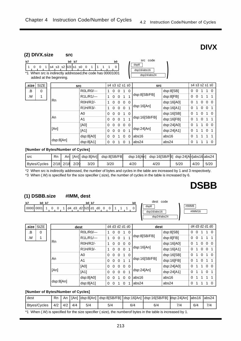
213
Chapter 4 Instruction Code/Number of Cycles 4.2 Instruction Code/Number of Cycles
(2) DIVX.size src
.size
.B
.W
SIZE
0
1
b7 b0 b7 b0
1 0 0 1 s4 s3 s2 SIZE s1 s0 0 1 1 1 1 0
dsp24/abs24
dsp8
dsp16/abs16 )(DIVX
src Rn An [An] dsp:8[An] dsp:8[SB/FB] dsp:16[An] dsp:16[SB/FB] dsp:24[An]abs16 abs24
Bytes/Cycles 2/18 2/18 2/20 3/20 3/20 4/20 4/20 5/20 4/20 5/20
R0L/R0/---
R1L/R1/---
R0H/R2/-
R1H/R3/-
A0
A1
[A0]
[A1]
dsp:8[A0]
dsp:8[A1]
dsp:8[SB/FB]
dsp:16[An]
dsp:16[SB/FB]
dsp:24[An]
abs16
abs24
Rn
An
[An]
dsp:8[An]
srcsrc s4 s3 s2 s1 s0
1 0 0 1 0
1 0 0 1 1
1 0 0 0 0
1 0 0 0 1
0 0 0 1 0
0 0 0 1 1
0 0 0 0 0
0 0 0 0 1
0 0 1 0 0
0 0 1 0 1
s4 s3 s2 s1 s0
0 0 1 1 0
0 0 1 1 1
0 1 0 0 0
0 1 0 0 1
0 1 0 1 0
0 1 0 1 1
0 1 1 0 0
0 1 1 0 1
0 1 1 1 1
0 1 1 1 0
dsp:8[SB]
dsp:8[FB]
dsp:16[A0]
dsp:16[A1]
dsp:16[SB]
dsp:16[FB]
dsp:24[A0]
dsp:24[A1]
abs16
abs24
DSBB(1) DSBB.size #IMM, dest
.size
.B
.W
SIZE
0
1
dest Rn An [An] dsp:8[An] dsp:8[SB/FB] dsp:16[An] dsp:16[SB/FB] dsp:24[An] abs16 abs24
Btyes/Cycles 4/2 4/2 4/4 5/4 5/4 6/4 6/4 7/4 6/4 7/4
R0L/R0/---
R1L/R1/---
R0H/R2/-
R1H/R3/-
A0
A1
[A0]
[A1]
dsp:8[A0]
dsp:8[A1]
dsp:8[SB/FB]
dsp:16[An]
dsp:16[SB/FB]
dsp:24[An]
abs16
abs24
Rn
An
[An]
dsp:8[An]
destdest d4 d3 d2 d1 d0
1 0 0 1 0
1 0 0 1 1
1 0 0 0 0
1 0 0 0 1
0 0 0 1 0
0 0 0 1 1
0 0 0 0 0
0 0 0 0 1
0 0 1 0 0
0 0 1 0 1
d4 d3 d2 d1 d0
0 0 1 1 0
0 0 1 1 1
0 1 0 0 0
0 1 0 0 1
0 1 0 1 0
0 1 0 1 1
0 1 1 0 0
0 1 1 0 1
0 1 1 1 1
0 1 1 1 0
dsp24/abs24
dsp8
dsp16/abs16 )(dsp:8[SB]
dsp:8[FB]
dsp:16[A0]
dsp:16[A1]
dsp:16[SB]
dsp:16[FB]
dsp:24[A0]
dsp:24[A1]
abs16
abs24
#IMM8
#IMM16
b7 b0 b7 b0 b7 b0
0000 0001 1 0 0 1 d4 d3 d2 SIZE d1 d0 0 0 1 1 1 0
*1 When src is indirectly addressed,the code has 00001001added at the beginning.
src code
[Number of Bytes/Number of Cycles]
*2 When src is indirectly addressed, the number of bytes and cycles in the table are increased by 1 and 3 respectively.*3 When (.W) is specified for the size specifier (.size), the number of cycles in the table is increased by 6.
dest code
[Number of Bytes/Number of Cycles]
*1 When (.W) is specified for the size specifier (.size), the numberof bytes in the table is increased by 1.
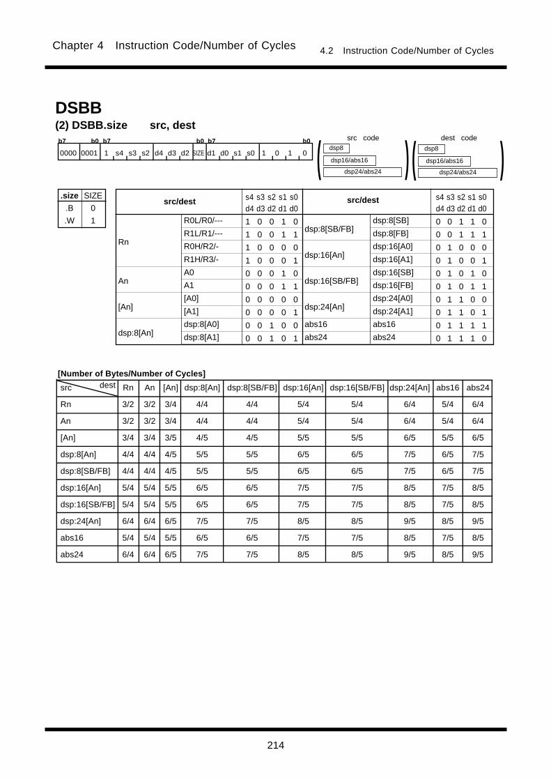
214
Chapter 4 Instruction Code/Number of Cycles 4.2 Instruction Code/Number of Cycles
src dest Rn An [An] dsp:8[An] dsp:8[SB/FB] dsp:16[An] dsp:16[SB/FB] dsp:24[An] abs16 abs24
Rn 3/2 3/2 3/4 4/4 4/4 5/4 5/4 6/4 5/4 6/4
An 3/2 3/2 3/4 4/4 4/4 5/4 5/4 6/4 5/4 6/4
[An] 3/4 3/4 3/5 4/5 4/5 5/5 5/5 6/5 5/5 6/5
dsp:8[An] 4/4 4/4 4/5 5/5 5/5 6/5 6/5 7/5 6/5 7/5
dsp:8[SB/FB] 4/4 4/4 4/5 5/5 5/5 6/5 6/5 7/5 6/5 7/5
dsp:16[An] 5/4 5/4 5/5 6/5 6/5 7/5 7/5 8/5 7/5 8/5
dsp:16[SB/FB] 5/4 5/4 5/5 6/5 6/5 7/5 7/5 8/5 7/5 8/5
dsp:24[An] 6/4 6/4 6/5 7/5 7/5 8/5 8/5 9/5 8/5 9/5
abs16 5/4 5/4 5/5 6/5 6/5 7/5 7/5 8/5 7/5 8/5
abs24 6/4 6/4 6/5 7/5 7/5 8/5 8/5 9/5 8/5 9/5
(2) DSBB.size src, dest
dsp24/abs24
dsp8
dsp16/abs16 )( dsp24/abs24
dsp8
dsp16/abs16 )(b7 b0 b7 b0 b7 b0
0000 0001 1 s4 s3 s2 d4 d3 d2 SIZE d1 d0 s1 s0 1 0 1 0
.size
.B
.W
SIZE
0
1 R0L/R0/---
R1L/R1/---
R0H/R2/-
R1H/R3/-
A0
A1
[A0]
[A1]
dsp:8[A0]
dsp:8[A1]
dsp:8[SB/FB]
dsp:16[An]
dsp:16[SB/FB]
dsp:24[An]
abs16
abs24
Rn
An
[An]
dsp:8[An]
src/destsrc/dest s4 s3 s2 s1 s0d4 d3 d2 d1 d0
1 0 0 1 0
1 0 0 1 1
1 0 0 0 0
1 0 0 0 1
0 0 0 1 0
0 0 0 1 1
0 0 0 0 0
0 0 0 0 1
0 0 1 0 0
0 0 1 0 1
s4 s3 s2 s1 s0d4 d3 d2 d1 d0
0 0 1 1 0
0 0 1 1 1
0 1 0 0 0
0 1 0 0 1
0 1 0 1 0
0 1 0 1 1
0 1 1 0 0
0 1 1 0 1
0 1 1 1 1
0 1 1 1 0
dsp:8[SB]
dsp:8[FB]
dsp:16[A0]
dsp:16[A1]
dsp:16[SB]
dsp:16[FB]
dsp:24[A0]
dsp:24[A1]
abs16
abs24
DSBB
src code dest code
[Number of Bytes/Number of Cycles]
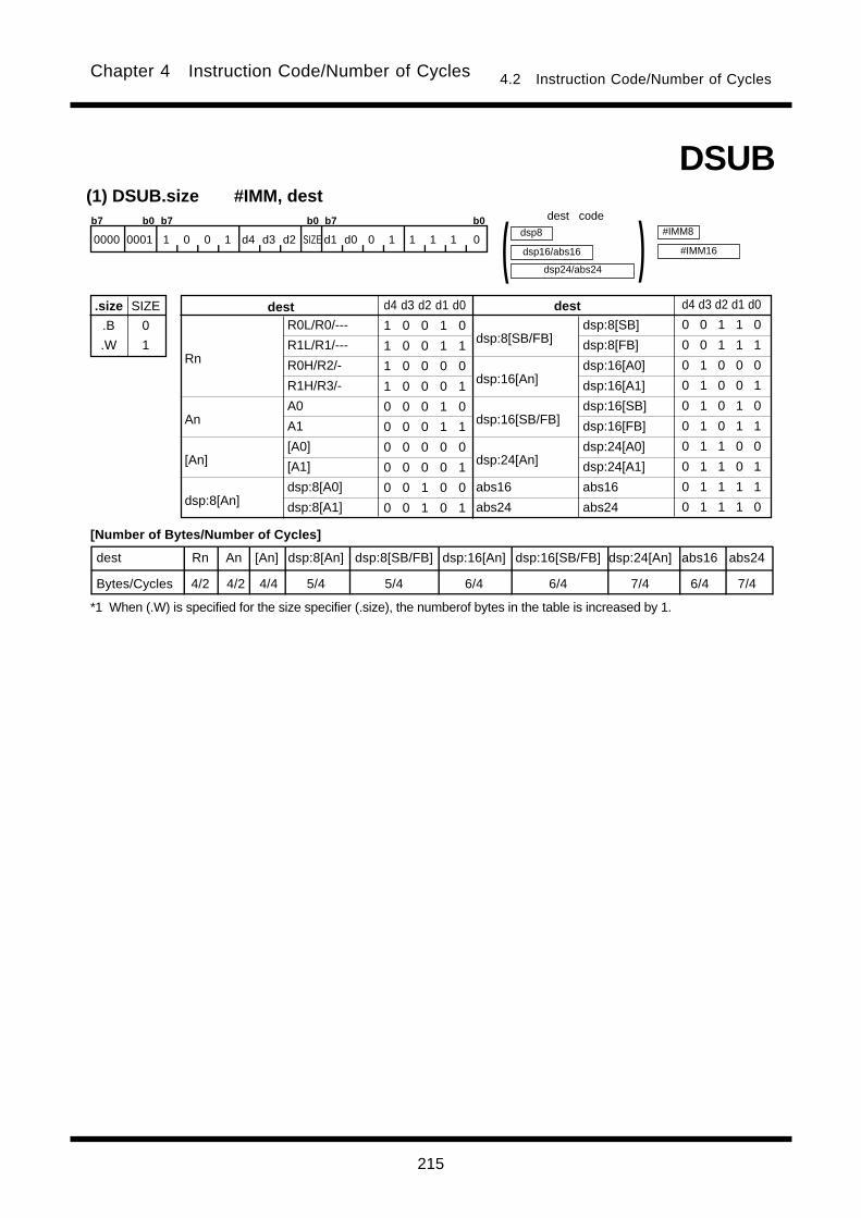
215
Chapter 4 Instruction Code/Number of Cycles 4.2 Instruction Code/Number of Cycles
(1) DSUB.size #IMM, dest
.size
.B
.W
SIZE
0
1
dest Rn An [An] dsp:8[An] dsp:8[SB/FB] dsp:16[An] dsp:16[SB/FB] dsp:24[An] abs16 abs24
Bytes/Cycles 4/2 4/2 4/4 5/4 5/4 6/4 6/4 7/4 6/4 7/4
R0L/R0/---
R1L/R1/---
R0H/R2/-
R1H/R3/-
A0
A1
[A0]
[A1]
dsp:8[A0]
dsp:8[A1]
dsp:8[SB/FB]
dsp:16[An]
dsp:16[SB/FB]
dsp:24[An]
abs16
abs24
Rn
An
[An]
dsp:8[An]
destdest d4 d3 d2 d1 d0
1 0 0 1 0
1 0 0 1 1
1 0 0 0 0
1 0 0 0 1
0 0 0 1 0
0 0 0 1 1
0 0 0 0 0
0 0 0 0 1
0 0 1 0 0
0 0 1 0 1
d4 d3 d2 d1 d0
0 0 1 1 0
0 0 1 1 1
0 1 0 0 0
0 1 0 0 1
0 1 0 1 0
0 1 0 1 1
0 1 1 0 0
0 1 1 0 1
0 1 1 1 1
0 1 1 1 0
dsp24/abs24
dsp8
dsp16/abs16 )(dsp:8[SB]
dsp:8[FB]
dsp:16[A0]
dsp:16[A1]
dsp:16[SB]
dsp:16[FB]
dsp:24[A0]
dsp:24[A1]
abs16
abs24
#IMM8
#IMM16
DSUB
b7 b0 b7 b0 b7 b0
0000 0001 1 0 0 1 d4 d3 d2 SIZE d1 d0 0 1 1 1 1 0
dest code
[Number of Bytes/Number of Cycles]
*1 When (.W) is specified for the size specifier (.size), the numberof bytes in the table is increased by 1.

216
Chapter 4 Instruction Code/Number of Cycles 4.2 Instruction Code/Number of Cycles
src dest Rn An [An] dsp:8[An] dsp:8[SB/FB] dsp:16[An] dsp:16[SB/FB] dsp:24[An] abs16 abs24
Rn 3/2 3/2 3/4 4/4 4/4 5/4 5/4 6/4 5/4 6/4
An 3/2 3/2 3/4 4/4 4/4 5/4 5/4 6/4 5/4 6/4
[An] 3/4 3/4 3/5 4/5 4/5 5/5 5/5 6/5 5/5 6/5
dsp:8[An] 4/4 4/4 4/5 5/5 5/5 6/5 6/5 7/5 6/5 7/5
dsp:8[SB/FB] 4/4 4/4 4/5 5/5 5/5 6/5 6/5 7/5 6/5 7/5
dsp:16[An] 5/4 5/4 5/5 6/5 6/5 7/5 7/5 8/5 7/5 8/5
dsp:16[SB/FB] 5/4 5/4 5/5 6/5 6/5 7/5 7/5 8/5 7/5 8/5
dsp:24[An] 6/4 6/4 6/5 7/5 7/5 8/5 8/5 9/5 8/5 9/5
abs16 5/4 5/4 5/5 6/5 6/5 7/5 7/5 8/5 7/5 8/5
abs24 6/4 6/4 6/5 7/5 7/5 8/5 8/5 9/5 8/5 9/5
(2) DSUB.size src, dest
dsp24/abs24
dsp8
dsp16/abs16 )( dsp24/abs24
dsp8
dsp16/abs16 )(DSUB
b7 b0 b7 b0 b7 b0
0000 0001 1 s4 s3 s2 d4 d3 d2 SIZE d1 d0 s1 s0 0 0 1 0
.size
.B
.W
SIZE
0
1 R0L/R0/---
R1L/R1/---
R0H/R2/-
R1H/R3/-
A0
A1
[A0]
[A1]
dsp:8[A0]
dsp:8[A1]
dsp:8[SB/FB]
dsp:16[An]
dsp:16[SB/FB]
dsp:24[An]
abs16
abs24
Rn
An
[An]
dsp:8[An]
src/destsrc/dest s4 s3 s2 s1 s0d4 d3 d2 d1 d0
1 0 0 1 0
1 0 0 1 1
1 0 0 0 0
1 0 0 0 1
0 0 0 1 0
0 0 0 1 1
0 0 0 0 0
0 0 0 0 1
0 0 1 0 0
0 0 1 0 1
s4 s3 s2 s1 s0d4 d3 d2 d1 d0
0 0 1 1 0
0 0 1 1 1
0 1 0 0 0
0 1 0 0 1
0 1 0 1 0
0 1 0 1 1
0 1 1 0 0
0 1 1 0 1
0 1 1 1 1
0 1 1 1 0
dsp:8[SB]
dsp:8[FB]
dsp:16[A0]
dsp:16[A1]
dsp:16[SB]
dsp:16[FB]
dsp:24[A0]
dsp:24[A1]
abs16
abs24
src code
[Number of Bytes/Number of Cycles]
dest code
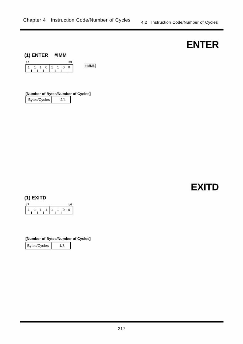
217
Chapter 4 Instruction Code/Number of Cycles 4.2 Instruction Code/Number of Cycles
(1) ENTER #IMM
#IMM8
ENTER
b7 b0
1 1 1 0 1 1 0 0
(1) EXITD
EXITD
b7 b0
1 1 1 1 1 1 0 0
Bytes/Cycles 2/4
[Number of Bytes/Number of Cycles]
Bytes/Cycles 1/8
[Number of Bytes/Number of Cycles]
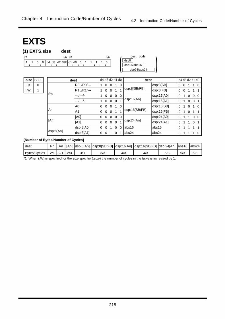
218
Chapter 4 Instruction Code/Number of Cycles 4.2 Instruction Code/Number of Cycles
b7 b0 b7 b0
1 1 0 0 d4 d3 d2 SIZE d1 d0 0 1 1 1 1 0
EXTS(1) EXTS.size dest
.size
.B
.W
SIZE
0
1
dest Rn An [An] dsp:8[An] dsp:8[SB/FB] dsp:16[An] dsp:16[SB/FB] dsp:24[An] abs16 abs24
Bytes/Cycles 2/1 2/1 2/3 3/3 3/3 4/3 4/3 5/3 5/3 5/3
R0L/R0/---
R1L/R1/---
---/---/-
---/---/-
A0
A1
[A0]
[A1]
dsp:8[A0]
dsp:8[A1]
dsp:8[SB/FB]
dsp:16[An]
dsp:16[SB/FB]
dsp:24[An]
abs16
abs24
Rn
An
[An]
dsp:8[An]
destdest d4 d3 d2 d1 d0
1 0 0 1 0
1 0 0 1 1
1 0 0 0 0
1 0 0 0 1
0 0 0 1 0
0 0 0 1 1
0 0 0 0 0
0 0 0 0 1
0 0 1 0 0
0 0 1 0 1
d4 d3 d2 d1 d0
0 0 1 1 0
0 0 1 1 1
0 1 0 0 0
0 1 0 0 1
0 1 0 1 0
0 1 0 1 1
0 1 1 0 0
0 1 1 0 1
0 1 1 1 1
0 1 1 1 0
dsp24/abs24
dsp8
dsp16/abs16 )(dsp:8[SB]
dsp:8[FB]
dsp:16[A0]
dsp:16[A1]
dsp:16[SB]
dsp:16[FB]
dsp:24[A0]
dsp:24[A1]
abs16
abs24
[Number of Bytes/Number of Cycles]
dest code
*1 When (.W) is specified for the size specifier(.size) the number of cycles in the table is increased by 1.

219
Chapter 4 Instruction Code/Number of Cycles 4.2 Instruction Code/Number of Cycles
src dest Rn An [An] dsp:8[An] dsp:8[SB/FB] dsp:16[An] dsp:16[SB/FB] dsp:24[An] abs16 abs24
Rn 3/1 3/1 3/3 4/3 4/3 5/3 5/3 6/3 5/3 6/3
[An] 3/3 3/3 3/4 4/4 4/4 5/4 5/4 6/4 5/4 6/4
dsp:8[An] 4/3 4/3 4/4 5/4 5/4 6/4 6/4 7/4 6/4 7/4
dsp:8[SB/FB] 4/3 4/3 4/4 5/4 5/4 6/4 6/4 7/4 6/4 7/4
dsp:16[An] 5/3 5/3 5/4 6/4 6/4 7/4 7/4 8/4 7/4 8/4
dsp:16[SB/FB] 5/3 5/3 5/4 6/4 6/4 7/4 7/4 8/4 7/4 8/4
dsp:24[An] 6/3 6/3 6/4 7/4 7/4 8/4 8/4 9/4 8/4 9/4
abs16 5/3 5/3 5/4 6/4 6/4 7/4 7/4 8/4 7/4 8/4
abs24 6/3 6/3 6/4 7/4 7/4 8/4 8/4 9/4 8/4 9/4
EXTS(2) EXTS.B src,destb7 b0 b7 b0 b7 b0
0000 0001 1 s4 s3 s2 d4 d3 d2 0 d1 d0 s1 s0 0 1 1 1
dsp24/abs24
dsp8
dsp16/abs16 )( dsp24/abs24
dsp8
dsp16/abs16 )(
---/R0/---
---/R1/---
---/R2/-
---/R3/-
A0
A1
[A0]
[A1]
dsp:8[A0]
dsp:8[A1]
dsp:8[SB/FB]
dsp:16[An]
dsp:16[SB/FB]
dsp:24[An]
abs16
abs24
Rn
An
[An]
dsp:8[An]
destdest d4 d3 d2 d1 d0
1 0 0 1 0
1 0 0 1 1
1 0 0 0 0
1 0 0 0 1
0 0 0 1 0
0 0 0 1 1
0 0 0 0 0
0 0 0 0 1
0 0 1 0 0
0 0 1 0 1
d4 d3 d2 d1 d0
0 0 1 1 0
0 0 1 1 1
0 1 0 0 0
0 1 0 0 1
0 1 0 1 0
0 1 0 1 1
0 1 1 0 0
0 1 1 0 1
0 1 1 1 1
0 1 1 1 0
dsp:8[SB]
dsp:8[FB]
dsp:16[A0]
dsp:16[A1]
dsp:16[SB]
dsp:16[FB]
dsp:24[A0]
dsp:24[A1]
abs16
abs24
R0L/---/---
R1L/---/---
R0H/---/-
R1H/---/-
---
---
[A0]
[A1]
dsp:8[A0]
dsp:8[A1]
dsp:8[SB/FB]
dsp:16[An]
dsp:16[SB/FB]
dsp:24[An]
abs16
abs24
Rn
An
[An]
dsp:8[An]
srcsrc s4 s3 s2 s1 s0
1 0 0 1 0
1 0 0 1 1
1 0 0 0 0
1 0 0 0 1
0 0 0 1 0
0 0 0 1 1
0 0 0 0 0
0 0 0 0 1
0 0 1 0 0
0 0 1 0 1
s4 s3 s2 s1s0
0 0 1 1 0
0 0 1 1 1
0 1 0 0 0
0 1 0 0 1
0 1 0 1 0
0 1 0 1 1
0 1 1 0 0
0 1 1 0 1
0 1 1 1 1
0 1 1 1 0
dsp:8[SB]
dsp:8[FB]
dsp:16[A0]
dsp:16[A1]
dsp:16[SB]
dsp:16[FB]
dsp:24[A0]
dsp:24[A1]
abs16
abs24
src code dest code
[Number of Bytes/Number of Cycles]
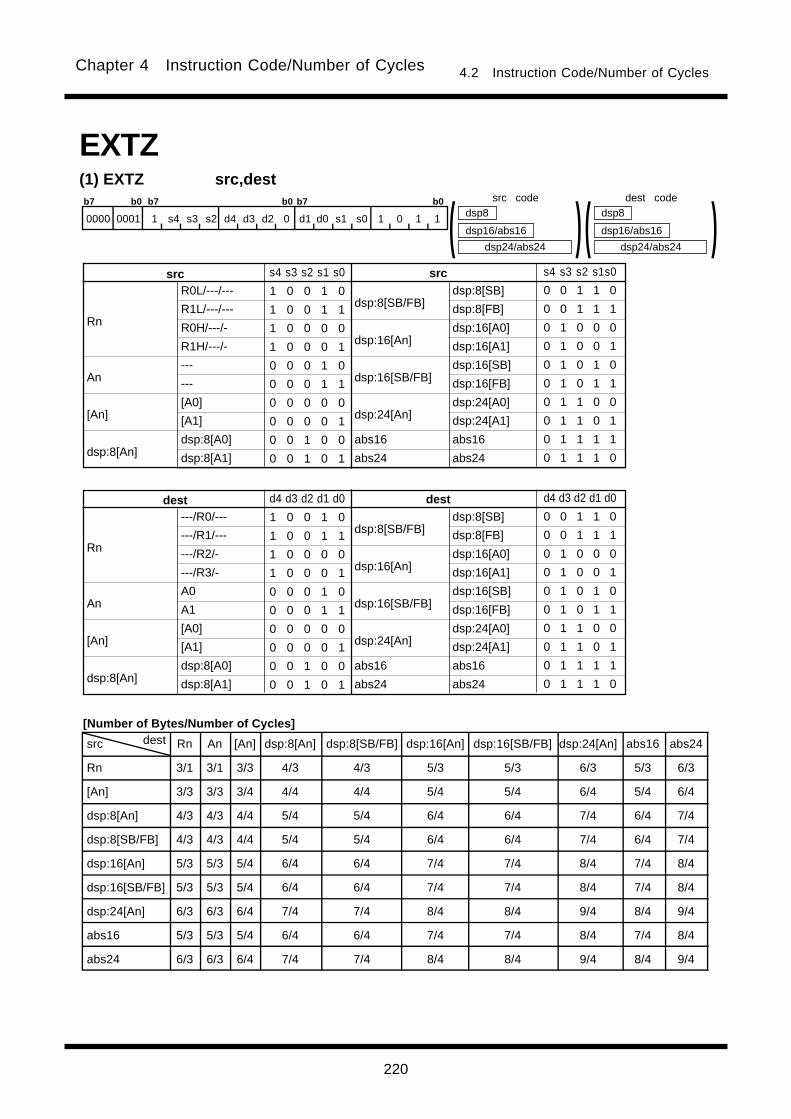
220
Chapter 4 Instruction Code/Number of Cycles 4.2 Instruction Code/Number of Cycles
src dest Rn An [An] dsp:8[An] dsp:8[SB/FB] dsp:16[An] dsp:16[SB/FB] dsp:24[An] abs16 abs24
Rn 3/1 3/1 3/3 4/3 4/3 5/3 5/3 6/3 5/3 6/3
[An] 3/3 3/3 3/4 4/4 4/4 5/4 5/4 6/4 5/4 6/4
dsp:8[An] 4/3 4/3 4/4 5/4 5/4 6/4 6/4 7/4 6/4 7/4
dsp:8[SB/FB] 4/3 4/3 4/4 5/4 5/4 6/4 6/4 7/4 6/4 7/4
dsp:16[An] 5/3 5/3 5/4 6/4 6/4 7/4 7/4 8/4 7/4 8/4
dsp:16[SB/FB] 5/3 5/3 5/4 6/4 6/4 7/4 7/4 8/4 7/4 8/4
dsp:24[An] 6/3 6/3 6/4 7/4 7/4 8/4 8/4 9/4 8/4 9/4
abs16 5/3 5/3 5/4 6/4 6/4 7/4 7/4 8/4 7/4 8/4
abs24 6/3 6/3 6/4 7/4 7/4 8/4 8/4 9/4 8/4 9/4
EXTZ(1) EXTZ src,destb7 b0 b7 b0 b7 b0
0000 0001 1 s4 s3 s2 d4 d3 d2 0 d1 d0 s1 s0 1 0 1 1
dsp24/abs24
dsp8
dsp16/abs16 )( dsp24/abs24
dsp8
dsp16/abs16 )(
---/R0/---
---/R1/---
---/R2/-
---/R3/-
A0
A1
[A0]
[A1]
dsp:8[A0]
dsp:8[A1]
dsp:8[SB/FB]
dsp:16[An]
dsp:16[SB/FB]
dsp:24[An]
abs16
abs24
Rn
An
[An]
dsp:8[An]
destdest d4 d3 d2 d1 d0
1 0 0 1 0
1 0 0 1 1
1 0 0 0 0
1 0 0 0 1
0 0 0 1 0
0 0 0 1 1
0 0 0 0 0
0 0 0 0 1
0 0 1 0 0
0 0 1 0 1
d4 d3 d2 d1 d0
0 0 1 1 0
0 0 1 1 1
0 1 0 0 0
0 1 0 0 1
0 1 0 1 0
0 1 0 1 1
0 1 1 0 0
0 1 1 0 1
0 1 1 1 1
0 1 1 1 0
dsp:8[SB]
dsp:8[FB]
dsp:16[A0]
dsp:16[A1]
dsp:16[SB]
dsp:16[FB]
dsp:24[A0]
dsp:24[A1]
abs16
abs24
R0L/---/---
R1L/---/---
R0H/---/-
R1H/---/-
---
---
[A0]
[A1]
dsp:8[A0]
dsp:8[A1]
dsp:8[SB/FB]
dsp:16[An]
dsp:16[SB/FB]
dsp:24[An]
abs16
abs24
Rn
An
[An]
dsp:8[An]
srcsrc s4 s3 s2 s1 s0
1 0 0 1 0
1 0 0 1 1
1 0 0 0 0
1 0 0 0 1
0 0 0 1 0
0 0 0 1 1
0 0 0 0 0
0 0 0 0 1
0 0 1 0 0
0 0 1 0 1
s4 s3 s2 s1s0
0 0 1 1 0
0 0 1 1 1
0 1 0 0 0
0 1 0 0 1
0 1 0 1 0
0 1 0 1 1
0 1 1 0 0
0 1 1 0 1
0 1 1 1 1
0 1 1 1 0
dsp:8[SB]
dsp:8[FB]
dsp:16[A0]
dsp:16[A1]
dsp:16[SB]
dsp:16[FB]
dsp:24[A0]
dsp:24[A1]
abs16
abs24
src code dest code
[Number of Bytes/Number of Cycles]
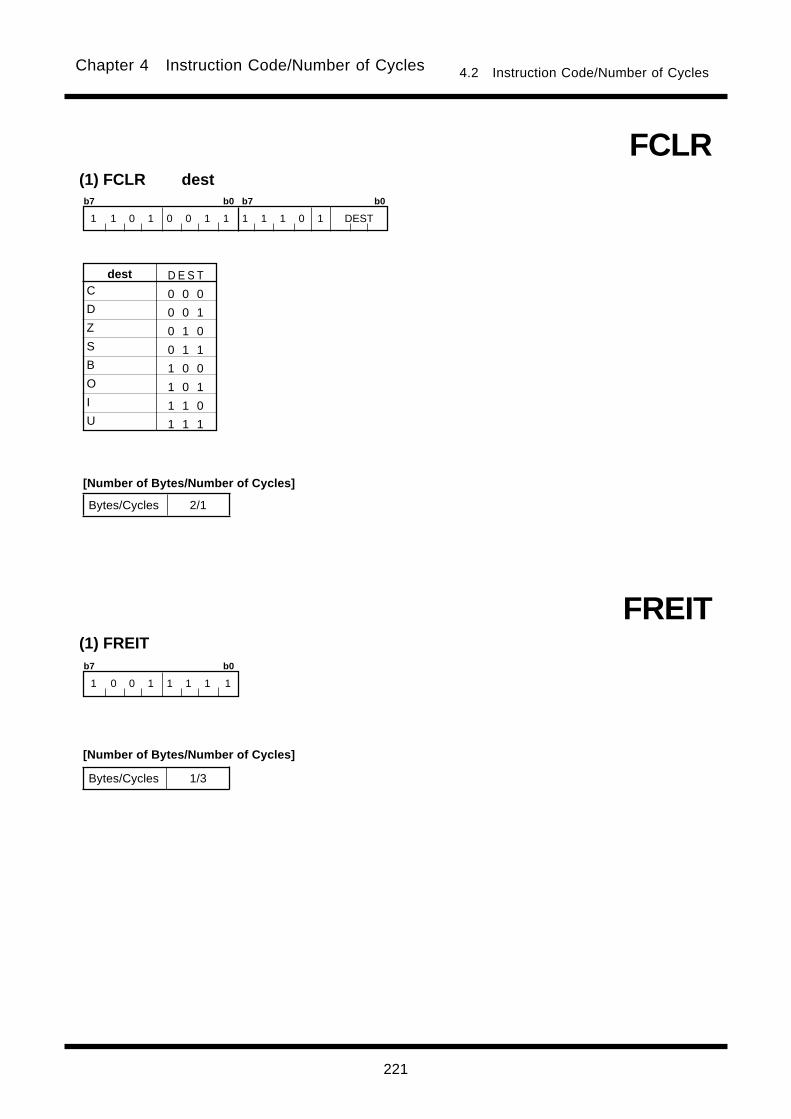
221
Chapter 4 Instruction Code/Number of Cycles 4.2 Instruction Code/Number of Cycles
(1) FCLR dest
C
D
Z
S
B
O
I
U
dest D E S T
0 0 0
0 0 1
0 1 0
0 1 1
1 0 0
1 0 1
1 1 0
1 1 1
FCLR
(1) FREITb7 b0
1 0 0 1 1 1 1 1
FREIT
b7 b0 b7 b0
1 1 0 1 0 0 1 1 1 1 1 0 1 DEST
Bytes/Cycles 2/1
Bytes/Cycles 1/3
[Number of Bytes/Number of Cycles]
[Number of Bytes/Number of Cycles]
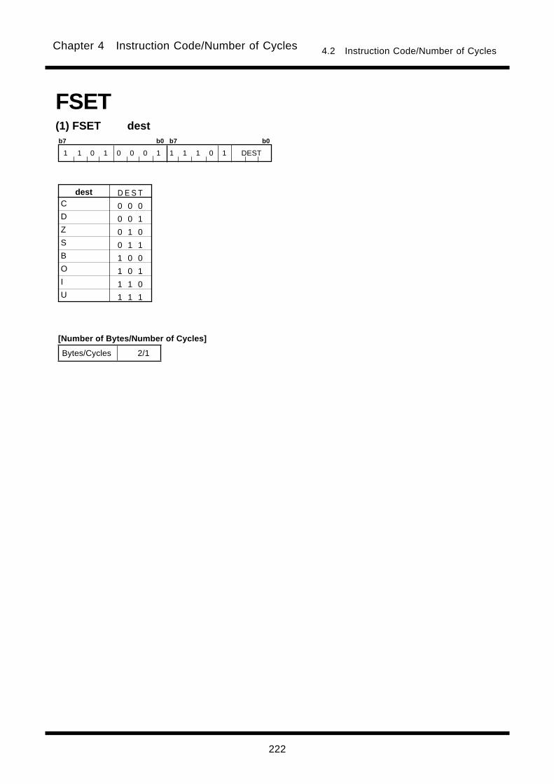
222
Chapter 4 Instruction Code/Number of Cycles 4.2 Instruction Code/Number of Cycles
(1) FSET dest
C
D
Z
S
B
O
I
U
dest D E S T
0 0 0
0 0 1
0 1 0
0 1 1
1 0 0
1 0 1
1 1 0
1 1 1
FSET
b7 b0 b7 b0
1 1 0 1 0 0 0 1 1 1 1 0 1 DEST
Bytes/Cycles 2/1
[Number of Bytes/Number of Cycles]

223
Chapter 4 Instruction Code/Number of Cycles 4.2 Instruction Code/Number of Cycles
(1) INC.size destb7 b0 b7 b0
1 0 1 0 d4 d3 d2 SIZE d1 d0 0 0 1 1 1 0
dsp24/abs24
dsp8
dsp16/abs16 )(INC
dest Rn An [An] dsp:8[An] dsp:8[SB/FB] dsp:16[An] dsp:16[SB/FB] dsp:24[An] abs16 abs24
Bytes/Cycles 2/1 2/1 2/3 3/3 3/3 4/3 4/3 5/3 4/3 5/3
.size
.B
.W
SIZE
0
1
R0L/R0/---
R1L/R1/---
R0H/R2/-
R1H/R3/-
A0
A1
[A0]
[A1]
dsp:8[A0]
dsp:8[A1]
dsp:8[SB/FB]
dsp:16[An]
dsp:16[SB/FB]
dsp:24[An]
abs16
abs24
Rn
An
[An]
dsp:8[An]
destdest d4 d3 d2 d1 d0
1 0 0 1 0
1 0 0 1 1
1 0 0 0 0
1 0 0 0 1
0 0 0 1 0
0 0 0 1 1
0 0 0 0 0
0 0 0 0 1
0 0 1 0 0
0 0 1 0 1
d4 d3 d2 d1 d0
0 0 1 1 0
0 0 1 1 1
0 1 0 0 0
0 1 0 0 1
0 1 0 1 0
0 1 0 1 1
0 1 1 0 0
0 1 1 0 1
0 1 1 1 1
0 1 1 1 0
dsp:8[SB]
dsp:8[FB]
dsp:16[A0]
dsp:16[A1]
dsp:16[SB]
dsp:16[FB]
dsp:24[A0]
dsp:24[A1]
abs16
abs24
(1) INDEXB.size srcb7 b0 b7 b0
1 0 0 0 s4 s3 s2 0 s1 s0 0 SIZE 0 0 1 1
dsp24/abs24
dsp8
dsp16/abs16 )(INDEXB
src Rn An [An] dsp:8[An] dsp:8[SB/FB] dsp:16[An] dsp:16[SB/FB] dsp:24[An] abs16 abs24
Bytes/Cycles 2/2 2/2 2/4 3/4 3/4 4/4 4/4 5/4 4/4 5/4
.size
.B
.W
SIZE
0
1
R0L/R0/---
R1L/R1/---
R0H/R2/-
R1H/R3/-
A0
A1
[A0]
[A1]
dsp:8[A0]
dsp:8[A1]
dsp:8[SB/FB]
dsp:16[An]
dsp:16[SB/FB]
dsp:24[An]
abs16
abs24
Rn
An
[An]
dsp:8[An]
srcsrc s4 s3 s2 s1 s0
1 0 0 1 0
1 0 0 1 1
1 0 0 0 0
1 0 0 0 1
0 0 0 1 0
0 0 0 1 1
0 0 0 0 0
0 0 0 0 1
0 0 1 0 0
0 0 1 0 1
s4 s3 s2 s1 s0
0 0 1 1 0
0 0 1 1 1
0 1 0 0 0
0 1 0 0 1
0 1 0 1 0
0 1 0 1 1
0 1 1 0 0
0 1 1 0 1
0 1 1 1 1
0 1 1 1 0
dsp:8[SB]
dsp:8[FB]
dsp:16[A0]
dsp:16[A1]
dsp:16[SB]
dsp:16[FB]
dsp:24[A0]
dsp:24[A1]
abs16
abs24
dest code
*1 When dest is indirectly addressed,the code has 00001001added at the beginning.
[Number of Bytes/Number of Cycles]
src code
*2 When dest is indirectly addressed, the number of bytes and cycles in the table are increased by 1 and 3 respectively.
[Number of Bytes/Number of Cycles]
*1 When (.W) is specified for the size specifier(.size) the number of cycles in the table is increased by 2.
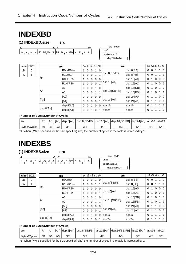
224
Chapter 4 Instruction Code/Number of Cycles 4.2 Instruction Code/Number of Cycles
(1) INDEXBD.size srcb7 b0 b7 b0
1 0 1 0 s4 s3 s2 0 s1 s0 0 SIZE 0 0 1 1
dsp24/abs24
dsp8
dsp16/abs16 )(INDEXBD
src Rn An [An] dsp:8[An] dsp:8[SB/FB] dsp:16[An] dsp:16[SB/FB] dsp:24[An] abs16 abs24
Bytes/Cycles 2/1 2/1 2/3 3/3 3/3 4/3 4/3 5/3 4/3 5/3
.size
.B
.W
SIZE
0
1
R0L/R0/---
R1L/R1/---
R0H/R2/-
R1H/R3/-
A0
A1
[A0]
[A1]
dsp:8[A0]
dsp:8[A1]
dsp:8[SB/FB]
dsp:16[An]
dsp:16[SB/FB]
dsp:24[An]
abs16
abs24
Rn
An
[An]
dsp:8[An]
srcsrc s4 s3 s2 s1 s0
1 0 0 1 0
1 0 0 1 1
1 0 0 0 0
1 0 0 0 1
0 0 0 1 0
0 0 0 1 1
0 0 0 0 0
0 0 0 0 1
0 0 1 0 0
0 0 1 0 1
s4 s3 s2 s1 s0
0 0 1 1 0
0 0 1 1 1
0 1 0 0 0
0 1 0 0 1
0 1 0 1 0
0 1 0 1 1
0 1 1 0 0
0 1 1 0 1
0 1 1 1 1
0 1 1 1 0
dsp:8[SB]
dsp:8[FB]
dsp:16[A0]
dsp:16[A1]
dsp:16[SB]
dsp:16[FB]
dsp:24[A0]
dsp:24[A1]
abs16
abs24
(1) INDEXBS.size srcb7 b0 b7 b0
1 1 0 0 s4 s3 s2 0 s1 s0 0 SIZE 0 0 1 1
dsp24/abs24
dsp8
dsp16/abs16 )(INDEXBS
src Rn An [An] dsp:8[An] dsp:8[SB/FB] dsp:16[An] dsp:16[SB/FB] dsp:24[An] abs16 abs24
Bytes/Cycles 2/1 2/1 2/3 3/3 3/3 4/3 4/3 5/3 4/3 5/3
.size
.B
.W
SIZE
0
1
R0L/R0/---
R1L/R1/---
R0H/R2/-
R1H/R3/-
A0
A1
[A0]
[A1]
dsp:8[A0]
dsp:8[A1]
dsp:8[SB/FB]
dsp:16[An]
dsp:16[SB/FB]
dsp:24[An]
abs16
abs24
Rn
An
[An]
dsp:8[An]
srcsrc s4 s3 s2 s1 s0
1 0 0 1 0
1 0 0 1 1
1 0 0 0 0
1 0 0 0 1
0 0 0 1 0
0 0 0 1 1
0 0 0 0 0
0 0 0 0 1
0 0 1 0 0
0 0 1 0 1
s4 s3 s2 s1 s0
0 0 1 1 0
0 0 1 1 1
0 1 0 0 0
0 1 0 0 1
0 1 0 1 0
0 1 0 1 1
0 1 1 0 0
0 1 1 0 1
0 1 1 1 1
0 1 1 1 0
dsp:8[SB]
dsp:8[FB]
dsp:16[A0]
dsp:16[A1]
dsp:16[SB]
dsp:16[FB]
dsp:24[A0]
dsp:24[A1]
abs16
abs24
src code
[Number of Bytes/Number of Cycles]
*1 When (.W) is specified for the size specifier(.size) the number of cycles in the table is increased by 1.
src code
[Number of Bytes/Number of Cycles]
*1 When (.W) is specified for the size specifier(.size) the number of cycles in the table is increased by 1.
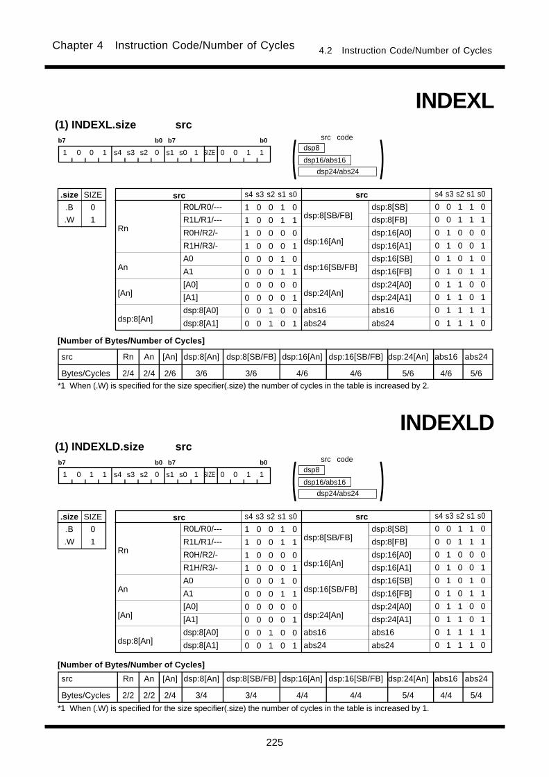
225
Chapter 4 Instruction Code/Number of Cycles 4.2 Instruction Code/Number of Cycles
(1) INDEXL.size srcb7 b0 b7 b0
1 0 0 1 s4 s3 s2 0 s1 s0 1 SIZE 0 0 1 1
dsp24/abs24
dsp8
dsp16/abs16 )(INDEXL
src Rn An [An] dsp:8[An] dsp:8[SB/FB] dsp:16[An] dsp:16[SB/FB] dsp:24[An] abs16 abs24
Bytes/Cycles 2/4 2/4 2/6 3/6 3/6 4/6 4/6 5/6 4/6 5/6
.size
.B
.W
SIZE
0
1
R0L/R0/---
R1L/R1/---
R0H/R2/-
R1H/R3/-
A0
A1
[A0]
[A1]
dsp:8[A0]
dsp:8[A1]
dsp:8[SB/FB]
dsp:16[An]
dsp:16[SB/FB]
dsp:24[An]
abs16
abs24
Rn
An
[An]
dsp:8[An]
srcsrc s4 s3 s2 s1 s0
1 0 0 1 0
1 0 0 1 1
1 0 0 0 0
1 0 0 0 1
0 0 0 1 0
0 0 0 1 1
0 0 0 0 0
0 0 0 0 1
0 0 1 0 0
0 0 1 0 1
s4 s3 s2 s1 s0
0 0 1 1 0
0 0 1 1 1
0 1 0 0 0
0 1 0 0 1
0 1 0 1 0
0 1 0 1 1
0 1 1 0 0
0 1 1 0 1
0 1 1 1 1
0 1 1 1 0
dsp:8[SB]
dsp:8[FB]
dsp:16[A0]
dsp:16[A1]
dsp:16[SB]
dsp:16[FB]
dsp:24[A0]
dsp:24[A1]
abs16
abs24
(1) INDEXLD.size srcb7 b0 b7 b0
1 0 1 1 s4 s3 s2 0 s1 s0 1 SIZE 0 0 1 1
dsp24/abs24
dsp8
dsp16/abs16 )(INDEXLD
src Rn An [An] dsp:8[An] dsp:8[SB/FB] dsp:16[An] dsp:16[SB/FB] dsp:24[An] abs16 abs24
Bytes/Cycles 2/2 2/2 2/4 3/4 3/4 4/4 4/4 5/4 4/4 5/4
.size
.B
.W
SIZE
0
1
R0L/R0/---
R1L/R1/---
R0H/R2/-
R1H/R3/-
A0
A1
[A0]
[A1]
dsp:8[A0]
dsp:8[A1]
dsp:8[SB/FB]
dsp:16[An]
dsp:16[SB/FB]
dsp:24[An]
abs16
abs24
Rn
An
[An]
dsp:8[An]
srcsrc s4 s3 s2 s1 s0
1 0 0 1 0
1 0 0 1 1
1 0 0 0 0
1 0 0 0 1
0 0 0 1 0
0 0 0 1 1
0 0 0 0 0
0 0 0 0 1
0 0 1 0 0
0 0 1 0 1
s4 s3 s2 s1 s0
0 0 1 1 0
0 0 1 1 1
0 1 0 0 0
0 1 0 0 1
0 1 0 1 0
0 1 0 1 1
0 1 1 0 0
0 1 1 0 1
0 1 1 1 1
0 1 1 1 0
dsp:8[SB]
dsp:8[FB]
dsp:16[A0]
dsp:16[A1]
dsp:16[SB]
dsp:16[FB]
dsp:24[A0]
dsp:24[A1]
abs16
abs24
src code
[Number of Bytes/Number of Cycles]
*1 When (.W) is specified for the size specifier(.size) the number of cycles in the table is increased by 2.
src code
[Number of Bytes/Number of Cycles]
*1 When (.W) is specified for the size specifier(.size) the number of cycles in the table is increased by 1.

226
Chapter 4 Instruction Code/Number of Cycles 4.2 Instruction Code/Number of Cycles
(1) INDEXLS.size srcb7 b0 b7 b0
1 0 0 1 s4 s3 s2 0 s1 s0 0 SIZE 0 0 1 1
dsp24/abs24
dsp8
dsp16/abs16 )(INDEXLS
src Rn An [An] dsp:8[An] dsp:8[SB/FB] dsp:16[An] dsp:16[SB/FB] dsp:24[An] abs16 abs24
Bytes/Cycles 2/2 2/2 2/4 3/4 3/4 4/4 4/4 5/4 4/4 5/4
.size
.B
.W
SIZE
0
1
R0L/R0/---
R1L/R1/---
R0H/R2/-
R1H/R3/-
A0
A1
[A0]
[A1]
dsp:8[A0]
dsp:8[A1]
dsp:8[SB/FB]
dsp:16[An]
dsp:16[SB/FB]
dsp:24[An]
abs16
abs24
Rn
An
[An]
dsp:8[An]
srcsrc s4 s3 s2 s1 s0
1 0 0 1 0
1 0 0 1 1
1 0 0 0 0
1 0 0 0 1
0 0 0 1 0
0 0 0 1 1
0 0 0 0 0
0 0 0 0 1
0 0 1 0 0
0 0 1 0 1
s4 s3 s2 s1 s0
0 0 1 1 0
0 0 1 1 1
0 1 0 0 0
0 1 0 0 1
0 1 0 1 0
0 1 0 1 1
0 1 1 0 0
0 1 1 0 1
0 1 1 1 1
0 1 1 1 0
dsp:8[SB]
dsp:8[FB]
dsp:16[A0]
dsp:16[A1]
dsp:16[SB]
dsp:16[FB]
dsp:24[A0]
dsp:24[A1]
abs16
abs24
(1) INDEXW.size srcb7 b0 b7 b0
1 0 0 0 s4 s3 s2 0 s1 s0 1 SIZE 0 0 1 1
dsp24/abs24
dsp8
dsp16/abs16 )(INDEXW
src Rn An [An] dsp:8[An] dsp:8[SB/FB] dsp:16[An] dsp:16[SB/FB] dsp:24[An] abs16 abs24
Bytes/Cycles 2/2 2/2 2/4 3/4 3/4 4/4 4/4 5/4 4/4 5/4
.size
.B
.W
SIZE
0
1
R0L/R0/---
R1L/R1/---
R0H/R2/-
R1H/R3/-
A0
A1
[A0]
[A1]
dsp:8[A0]
dsp:8[A1]
dsp:8[SB/FB]
dsp:16[An]
dsp:16[SB/FB]
dsp:24[An]
abs16
abs24
Rn
An
[An]
dsp:8[An]
srcsrc s4 s3 s2 s1 s0
1 0 0 1 0
1 0 0 1 1
1 0 0 0 0
1 0 0 0 1
0 0 0 1 0
0 0 0 1 1
0 0 0 0 0
0 0 0 0 1
0 0 1 0 0
0 0 1 0 1
s4 s3 s2 s1 s0
0 0 1 1 0
0 0 1 1 1
0 1 0 0 0
0 1 0 0 1
0 1 0 1 0
0 1 0 1 1
0 1 1 0 0
0 1 1 0 1
0 1 1 1 1
0 1 1 1 0
dsp:8[SB]
dsp:8[FB]
dsp:16[A0]
dsp:16[A1]
dsp:16[SB]
dsp:16[FB]
dsp:24[A0]
dsp:24[A1]
abs16
abs24
src code
[Number of Bytes/Number of Cycles]
*1 When (.W) is specified for the size specifier(.size) the number of cycles in the table is increased by 1.
src code
[Number of Bytes/Number of Cycles]
*1 When (.W) is specified for the size specifier(.size) the number of cycles in the table is increased by 2.

227
Chapter 4 Instruction Code/Number of Cycles 4.2 Instruction Code/Number of Cycles
(1) INDEXWD.size srcb7 b0 b7 b0
1 0 1 0 s4 s3 s2 0 s1 s0 1 SIZE 0 0 1 1
dsp24/abs24
dsp8
dsp16/abs16 )(INDEXWD
src Rn An [An] dsp:8[An] dsp:8[SB/FB] dsp:16[An] dsp:16[SB/FB] dsp:24[An] abs16 abs24
Bytes/Cycles 2/1 2/1 2/3 3/3 3/3 4/3 4/3 5/3 4/3 5/3
.size
.B
.W
SIZE
0
1
R0L/R0/---
R1L/R1/---
R0H/R2/-
R1H/R3/-
A0
A1
[A0]
[A1]
dsp:8[A0]
dsp:8[A1]
dsp:8[SB/FB]
dsp:16[An]
dsp:16[SB/FB]
dsp:24[An]
abs16
abs24
Rn
An
[An]
dsp:8[An]
srcsrc s4 s3 s2 s1 s0
1 0 0 1 0
1 0 0 1 1
1 0 0 0 0
1 0 0 0 1
0 0 0 1 0
0 0 0 1 1
0 0 0 0 0
0 0 0 0 1
0 0 1 0 0
0 0 1 0 1
s4 s3 s2 s1 s0
0 0 1 1 0
0 0 1 1 1
0 1 0 0 0
0 1 0 0 1
0 1 0 1 0
0 1 0 1 1
0 1 1 0 0
0 1 1 0 1
0 1 1 1 1
0 1 1 1 0
dsp:8[SB]
dsp:8[FB]
dsp:16[A0]
dsp:16[A1]
dsp:16[SB]
dsp:16[FB]
dsp:24[A0]
dsp:24[A1]
abs16
abs24
(1) INDEXWS.size srcb7 b0 b7 b0
1 1 0 0 s4 s3 s2 0 s1 s0 1 SIZE 0 0 1 1
dsp24/abs24
dsp8
dsp16/abs16 )(INDEXWS
src Rn An [An] dsp:8[An] dsp:8[SB/FB] dsp:16[An] dsp:16[SB/FB] dsp:24[An] abs16 abs24
Bytes/Cycles 2/1 2/1 2/3 3/3 3/3 4/3 4/3 5/3 4/3 5/3
.size
.B
.W
SIZE
0
1
R0L/R0/---
R1L/R1/---
R0H/R2/-
R1H/R3/-
A0
A1
[A0]
[A1]
dsp:8[A0]
dsp:8[A1]
dsp:8[SB/FB]
dsp:16[An]
dsp:16[SB/FB]
dsp:24[An]
abs16
abs24
Rn
An
[An]
dsp:8[An]
srcsrc s4 s3 s2 s1 s0
1 0 0 1 0
1 0 0 1 1
1 0 0 0 0
1 0 0 0 1
0 0 0 1 0
0 0 0 1 1
0 0 0 0 0
0 0 0 0 1
0 0 1 0 0
0 0 1 0 1
s4 s3 s2 s1 s0
0 0 1 1 0
0 0 1 1 1
0 1 0 0 0
0 1 0 0 1
0 1 0 1 0
0 1 0 1 1
0 1 1 0 0
0 1 1 0 1
0 1 1 1 1
0 1 1 1 0
dsp:8[SB]
dsp:8[FB]
dsp:16[A0]
dsp:16[A1]
dsp:16[SB]
dsp:16[FB]
dsp:24[A0]
dsp:24[A1]
abs16
abs24
src code
[Number of Bytes/Number of Cycles]
*1 When (.W) is specified for the size specifier(.size) the number of cycles in the table is increased by 1.
src code
[Number of Bytes/Number of Cycles]
*1 When (.W) is specified for the size specifier(.size) the number of cycles in the table is increased by 1.
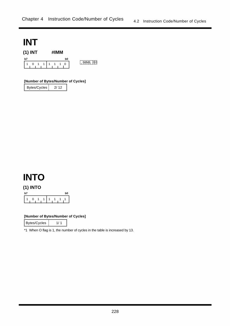
228
Chapter 4 Instruction Code/Number of Cycles 4.2 Instruction Code/Number of Cycles
(1) INT #IMMb7 b0
1 0 1 1 1 1 1 0 IMM6 0 0
INT
(1) INTOb7 b0
1 0 1 1 1 1 1 1
INTO
Bytes/Cycles 2/ 12
Bytes/Cycles 1/ 1
*1 When O flag is 1, the number of cycles in the table is increased by 13.
[Number of Bytes/Number of Cycles]
[Number of Bytes/Number of Cycles]
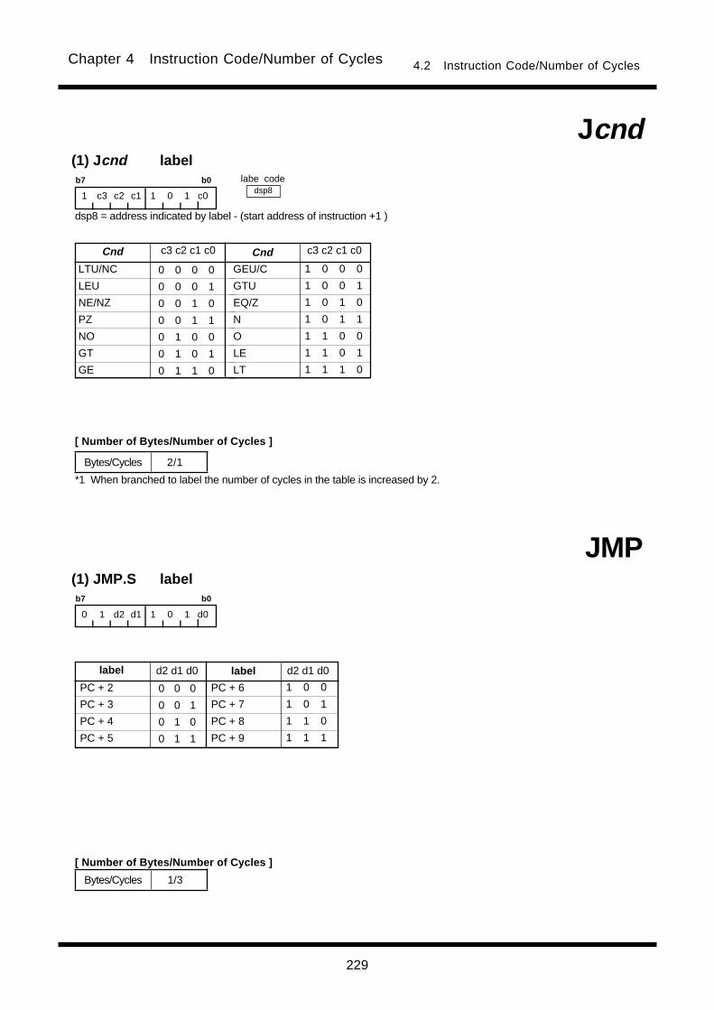
229
Chapter 4 Instruction Code/Number of Cycles 4.2 Instruction Code/Number of Cycles
(1) Jcnd label
dsp8
Jcnd
*1 When branched to label the number of cycles in the table is increased by 2.
b7 b0
1 c3 c2 c1 1 0 1 c0
(1) JMP.S label
JMP
b7 b0
0 1 d2 d1 1 0 1 d0
GEU/C
GTU
EQ/Z
N
O
LE
LT
LTU/NC
LEU
NE/NZ
PZ
NO
GT
GE
0 0 0 0
0 0 0 1
0 0 1 0
0 0 1 1
0 1 0 0
0 1 0 1
0 1 1 0
Cnd c3 c2 c1 c0 Cnd c3 c2 c1 c0
1 0 0 0
1 0 0 1
1 0 1 0
1 0 1 1
1 1 0 0
1 1 0 1
1 1 1 0
labe code
Bytes/Cycles 2/1
Bytes/Cycles 1/3
PC + 6
PC + 7
PC + 8
PC + 9
PC + 2
PC + 3
PC + 4
PC + 5
0 0 0
0 0 1
0 1 0
0 1 1
label d2 d1 d0 label d2 d1 d0
1 0 0
1 0 1
1 1 0
1 1 1
[ Number of Bytes/Number of Cycles ]
[ Number of Bytes/Number of Cycles ]
dsp8 = address indicated by label - (start address of instruction +1 )
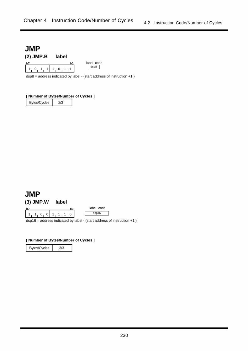
230
Chapter 4 Instruction Code/Number of Cycles 4.2 Instruction Code/Number of Cycles
label codedsp8
dsp16
(2) JMP.B labelJMP
b7 b0
1 0 1 1 1 0 1 1
dsp8 = address indicated by label - (start address of instruction +1 )
(3) JMP.W labelJMP
b7 b0
1 1 0 0 1 1 1 0
label code
Bytes/Cycles 2/3
Bytes/Cycles 3/3
[ Number of Bytes/Number of Cycles ]
dsp16 = address indicated by label - (start address of instruction +1 )
[ Number of Bytes/Number of Cycles ]
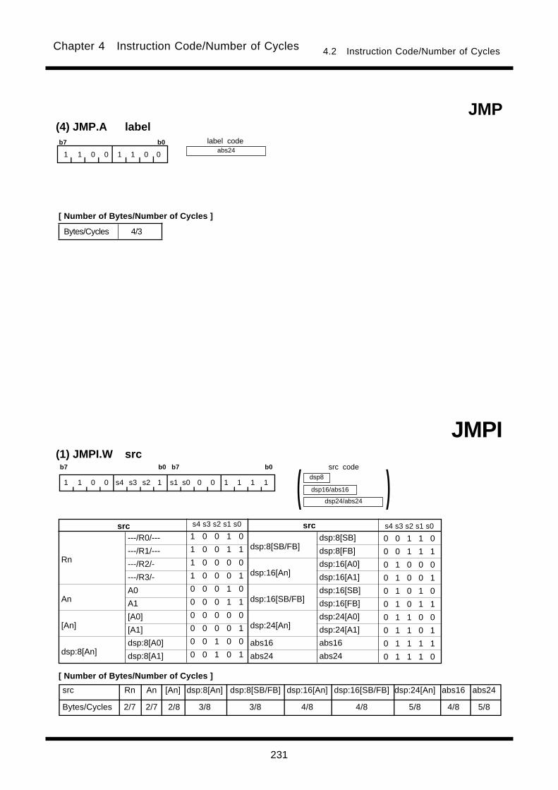
231
Chapter 4 Instruction Code/Number of Cycles 4.2 Instruction Code/Number of Cycles
abs24label code
(4) JMP.A labelJMP
b7 b0
1 1 0 0 1 1 0 0
(1) JMPI.W src
JMPIb7 b0 b7 b0
1 1 0 0 s4 s3 s2 1 s1 s0 0 0 1 1 1 1
dsp24/abs24
dsp8
dsp16/abs16 )(
src Rn An [An] dsp:8[An] dsp:8[SB/FB] dsp:16[An] dsp:16[SB/FB] dsp:24[An] abs16 abs24
Bytes/Cycles 2/7 2/7 2/8 3/8 3/8 4/8 4/8 5/8 4/8 5/8
---/R0/---
---/R1/---
---/R2/-
---/R3/-
A0
A1
[A0]
[A1]
dsp:8[A0]
dsp:8[A1]
dsp:8[SB/FB]
dsp:16[An]
dsp:16[SB/FB]
dsp:24[An]
abs16
abs24
Rn
An
[An]
dsp:8[An]
srcsrc s4 s3 s2 s1 s0
1 0 0 1 0
1 0 0 1 1
1 0 0 0 0
1 0 0 0 1
0 0 0 1 0
0 0 0 1 1
0 0 0 0 0
0 0 0 0 1
0 0 1 0 0
0 0 1 0 1
s4 s3 s2 s1 s0
0 0 1 1 0
0 0 1 1 1
0 1 0 0 0
0 1 0 0 1
0 1 0 1 0
0 1 0 1 1
0 1 1 0 0
0 1 1 0 1
0 1 1 1 1
0 1 1 1 0
dsp:8[SB]
dsp:8[FB]
dsp:16[A0]
dsp:16[A1]
dsp:16[SB]
dsp:16[FB]
dsp:24[A0]
dsp:24[A1]
abs16
abs24
Bytes/Cycles 4/3
[ Number of Bytes/Number of Cycles ]
src code
[ Number of Bytes/Number of Cycles ]
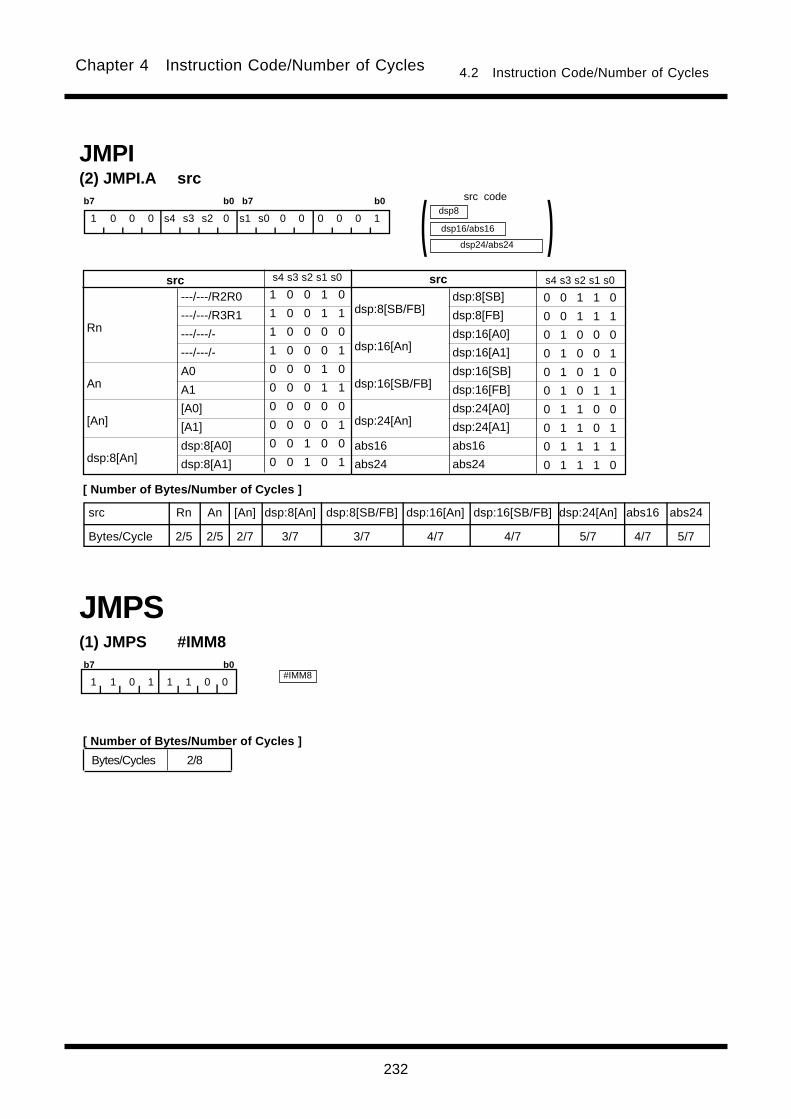
232
Chapter 4 Instruction Code/Number of Cycles 4.2 Instruction Code/Number of Cycles
Bytes/Cycles 2/8
(1) JMPS #IMM8b7 b0
1 1 0 1 1 1 0 0
JMPS
(2) JMPI.A srcJMPI
b7 b0 b7 b0
1 0 0 0 s4 s3 s2 0 s1 s0 0 0 0 0 0 1
dsp24/abs24
dsp8
dsp16/abs16 )(
src Rn An [An] dsp:8[An] dsp:8[SB/FB] dsp:16[An] dsp:16[SB/FB] dsp:24[An] abs16 abs24
Bytes/Cycle 2/5 2/5 2/7 3/7 3/7 4/7 4/7 5/7 4/7 5/7
---/---/R2R0
---/---/R3R1
---/---/-
---/---/-
A0
A1
[A0]
[A1]
dsp:8[A0]
dsp:8[A1]
dsp:8[SB/FB]
dsp:16[An]
dsp:16[SB/FB]
dsp:24[An]
abs16
abs24
Rn
An
[An]
dsp:8[An]
srcsrc s4 s3 s2 s1 s0
1 0 0 1 0
1 0 0 1 1
1 0 0 0 0
1 0 0 0 1
0 0 0 1 0
0 0 0 1 1
0 0 0 0 0
0 0 0 0 1
0 0 1 0 0
0 0 1 0 1
s4 s3 s2 s1 s0
0 0 1 1 0
0 0 1 1 1
0 1 0 0 0
0 1 0 0 1
0 1 0 1 0
0 1 0 1 1
0 1 1 0 0
0 1 1 0 1
0 1 1 1 1
0 1 1 1 0
dsp:8[SB]
dsp:8[FB]
dsp:16[A0]
dsp:16[A1]
dsp:16[SB]
dsp:16[FB]
dsp:24[A0]
dsp:24[A1]
abs16
abs24
#IMM8
src code
[ Number of Bytes/Number of Cycles ]
[ Number of Bytes/Number of Cycles ]
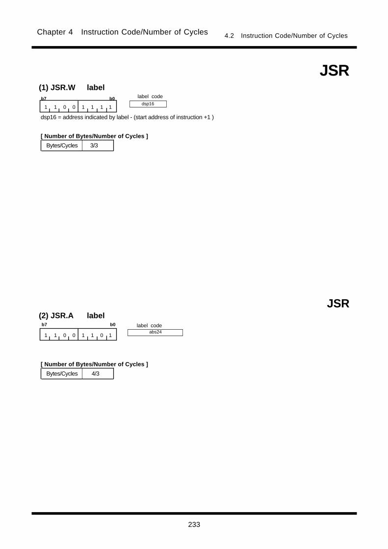
233
Chapter 4 Instruction Code/Number of Cycles 4.2 Instruction Code/Number of Cycles
Bytes/Cycles 4/3
(2) JSR.A labelb7 b0
1 1 0 0 1 1 0 1
JSR
label code
dsp16
Bytes/Cycles 3/3
(1) JSR.W labelb7 b0
1 1 0 0 1 1 1 1
JSR
label code
abs24
[ Number of Bytes/Number of Cycles ]
[ Number of Bytes/Number of Cycles ]
dsp16 = address indicated by label - (start address of instruction +1 )
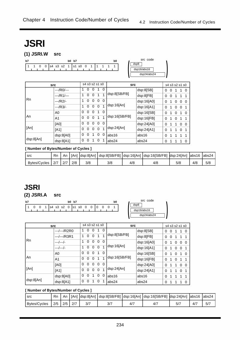
234
Chapter 4 Instruction Code/Number of Cycles 4.2 Instruction Code/Number of Cycles
(2) JSRI.A srcb7 b0 b7 b0
1 0 0 1 s4 s3 s2 0 s1 s0 0 0 0 0 0 1
dsp24/abs24
dsp8
dsp16/abs16 )(
JSRI
src Rn An [An] dsp:8[An] dsp:8[SB/FB] dsp:16[An] dsp:16[SB/FB] dsp:24[An] abs16 abs24
Bytes/Cycles 2/5 2/5 2/7 3/7 3/7 4/7 4/7 5/7 4/7 5/7
(1) JSRI.W srcb7 b0 b7 b0
1 1 0 0 s4 s3 s2 1 s1 s0 0 1 1 1 1 1
dsp24/abs24
dsp8
dsp16/abs16 )(
JSRI
src Rn An [An] dsp:8[An] dsp:8[SB/FB] dsp:16[An] dsp:16[SB/FB] dsp:24[An] abs16 abs24
Bytes/Cycles 2/7 2/7 2/8 3/8 3/8 4/8 4/8 5/8 4/8 5/8
---/R0/---
---/R1/---
---/R2/-
---/R3/-
A0
A1
[A0]
[A1]
dsp:8[A0]
dsp:8[A1]
dsp:8[SB/FB]
dsp:16[An]
dsp:16[SB/FB]
dsp:24[An]
abs16
abs24
Rn
An
[An]
dsp:8[An]
srcsrc s4 s3 s2 s1 s0
1 0 0 1 0
1 0 0 1 1
1 0 0 0 0
1 0 0 0 1
0 0 0 1 0
0 0 0 1 1
0 0 0 0 0
0 0 0 0 1
0 0 1 0 0
0 0 1 0 1
s4 s3 s2 s1 s0
0 0 1 1 0
0 0 1 1 1
0 1 0 0 0
0 1 0 0 1
0 1 0 1 0
0 1 0 1 1
0 1 1 0 0
0 1 1 0 1
0 1 1 1 1
0 1 1 1 0
dsp:8[SB]
dsp:8[FB]
dsp:16[A0]
dsp:16[A1]
dsp:16[SB]
dsp:16[FB]
dsp:24[A0]
dsp:24[A1]
abs16
abs24
---/---/R2R0
---/---/R3R1
---/---/-
---/---/-
A0
A1
[A0]
[A1]
dsp:8[A0]
dsp:8[A1]
dsp:8[SB/FB]
dsp:16[An]
dsp:16[SB/FB]
dsp:24[An]
abs16
abs24
Rn
An
[An]
dsp:8[An]
srcsrc s4 s3 s2 s1 s0
1 0 0 1 0
1 0 0 1 1
1 0 0 0 0
1 0 0 0 1
0 0 0 1 0
0 0 0 1 1
0 0 0 0 0
0 0 0 0 1
0 0 1 0 0
0 0 1 0 1
s4 s3 s2 s1 s0
0 0 1 1 0
0 0 1 1 1
0 1 0 0 0
0 1 0 0 1
0 1 0 1 0
0 1 0 1 1
0 1 1 0 0
0 1 1 0 1
0 1 1 1 1
0 1 1 1 0
dsp:8[SB]
dsp:8[FB]
dsp:16[A0]
dsp:16[A1]
dsp:16[SB]
dsp:16[FB]
dsp:24[A0]
dsp:24[A1]
abs16
abs24
src code
[ Number of Bytes/Number of Cycles ]
src code
[ Number of Bytes/Number of Cycles ]
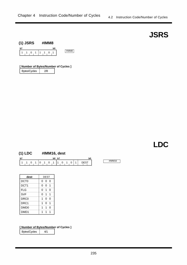
235
Chapter 4 Instruction Code/Number of Cycles 4.2 Instruction Code/Number of Cycles
Bytes/Cycles 2/8
(1) JSRS #IMM8b7 b0
1 1 0 1 1 1 0 1
JSRS
#IMM8
(1) LDC #IMM16, destb7 b0 b7 b0
1 1 0 1 0 1 0 1 1 0 1 0 1 DEST
LDC
DCT0
DCT1
FLG
SVF
DRC0
DRC1
DMD0
DMD1
dest DEST
0 0 0
0 0 1
0 1 0
0 1 1
1 0 0
1 0 1
1 1 0
1 1 1
#IMM16
Bytes/Cycles 4/1
[ Number of Bytes/Number of Cycles ]
[ Number of Bytes/Number of Cycles ]

236
Chapter 4 Instruction Code/Number of Cycles 4.2 Instruction Code/Number of Cycles
(2) LDC #IMM24, destb7 b0 b7 b0
1 1 0 1 0 1 0 1 0 0 1 0 1 DEST
LDC
INTB
SP
SB
FB
SVP
VCT
---
ISP
dest DEST
0 0 0
0 0 1
0 1 0
0 1 1
1 0 0
1 0 1
1 1 0
1 1 1
#IMM24
Bytes/Cycles 5/2
(3) LDC #IMM24, destb7 b0 b7 b0
1 1 0 1 0 1 0 1 0 1 1 0 1 DEST
LDC
---
---
DMA0
DMA1
DRA0
DRA1
DSA0
DSA1
dest DEST
0 0 0
0 0 1
0 1 0
0 1 1
1 0 0
1 0 1
1 1 0
1 1 1
#IMM24
Bytes/Cycles 5/2
[ Number of Bytes/Number of Cycles ]
[ Number of Bytes/Number of Cycles ]

237
Chapter 4 Instruction Code/Number of Cycles 4.2 Instruction Code/Number of Cycles
0000 0001 1 1 0 1 s4 s3 s2 1 s1 s0 0 0 1 DEST
---/R0/---
---/R1/---
---/R2/-
---/R3/-
A0
A1
[A0]
[A1]
dsp:8[A0]
dsp:8[A1]
dsp:8[SB/FB]
dsp:16[An]
dsp:16[SB/FB]
dsp:24[An]
abs16
abs24
Rn
An
[An]
dsp:8[An]
srcsrc s4 s3 s2 s1 s0
1 0 0 1 0
1 0 0 1 1
1 0 0 0 0
1 0 0 0 1
0 0 0 1 0
0 0 0 1 1
0 0 0 0 0
0 0 0 0 1
0 0 1 0 0
0 0 1 0 1
s4 s3 s2 s1 s0
0 0 1 1 0
0 0 1 1 1
0 1 0 0 0
0 1 0 0 1
0 1 0 1 0
0 1 0 1 1
0 1 1 0 0
0 1 1 0 1
0 1 1 1 1
0 1 1 1 0
dsp:8[SB]
dsp:8[FB]
dsp:16[A0]
dsp:16[A1]
dsp:16[SB]
dsp:16[FB]
dsp:24[A0]
dsp:24[A1]
abs16
abs24
(4) LDC src, dest
dsp24/abs24
dsp8
dsp16/abs16 )(LDC
DCT0
DCT1
FLG
SVF
DRC0
DRC1
DMD0
DMD1
dest DEST
0 0 0
0 0 1
0 1 0
0 1 1
1 0 0
1 0 1
1 1 0
1 1 1
b7 b0 b7 b0 b7 b0
src Rn An [An] dsp:8[An] dsp:8[SB/FB] dsp:16[An] dsp:16[SB/FB] dsp:24[An] abs16 abs24
Bytes/Cyclse 3/1 3/1 3/3 4/3 4/3 5/3 5/3 6/3 5/3 6/3
---/---/R2R0
---/---/R3R1
---/---/-
---/---/-
A0
A1
[A0]
[A1]
dsp:8[A0]
dsp:8[A1]
dsp:8[SB/FB]
dsp:16[An]
dsp:16[SB/FB]
dsp:24[An]
abs16
abs24
Rn
An
[An]
dsp:8[An]
srcsrc s4 s3 s2 s1 s0
1 0 0 1 0
1 0 0 1 1
1 0 0 0 0
1 0 0 0 1
0 0 0 1 0
0 0 0 1 1
0 0 0 0 0
0 0 0 0 1
0 0 1 0 0
0 0 1 0 1
s4 s3 s2 s1 s0
0 0 1 1 0
0 0 1 1 1
0 1 0 0 0
0 1 0 0 1
0 1 0 1 0
0 1 0 1 1
0 1 1 0 0
0 1 1 0 1
0 1 1 1 1
0 1 1 1 0
dsp:8[SB]
dsp:8[FB]
dsp:16[A0]
dsp:16[A1]
dsp:16[SB]
dsp:16[FB]
dsp:24[A0]
dsp:24[A1]
abs16
abs24
(5) LDC src, destb7 b0 b7 b0
1 1 0 1 s4 s3 s2 1 s1 s0 0 0 0 DEST
dsp24/abs24
dsp8
dsp16/abs16 )(LDC
INTB
SP
SB
FB
SVP
VCT
---
ISP
dest DEST
0 0 0
0 0 1
0 1 0
0 1 1
1 0 0
1 0 1
1 1 0
1 1 1
src Rn An [An] dsp:8[An] dsp:8[SB/FB] dsp:16[An] dsp:16[SB/FB] dsp:24[An] abs16 abs24
Bytes/Cycles 2/2 2/2 2/6 3/6 3/6 4/6 4/6 5/6 4/6 5/6
[ Number of Bytes/Number of Cycles ]
[ Number of Bytes/Number of Cycles ]
src code
src code

238
Chapter 4 Instruction Code/Number of Cycles 4.2 Instruction Code/Number of Cycles
0000 0001 1 1 0 1 s4 s3 s2 1 s1 s0 0 0 0 DEST
---/---/R2R0
---/---/R3R1
---/---/-
---/---/-
A0
A1
[A0]
[A1]
dsp:8[A0]
dsp:8[A1]
dsp:8[SB/FB]
dsp:16[An]
dsp:16[SB/FB]
dsp:24[An]
abs16
abs24
Rn
An
[An]
dsp:8[An]
srcsrc s4 s3 s2 s1 s0
1 0 0 1 0
1 0 0 1 1
1 0 0 0 0
1 0 0 0 1
0 0 0 1 0
0 0 0 1 1
0 0 0 0 0
0 0 0 0 1
0 0 1 0 0
0 0 1 0 1
s4 s3 s2 s1 s0
0 0 1 1 0
0 0 1 1 1
0 1 0 0 0
0 1 0 0 1
0 1 0 1 0
0 1 0 1 1
0 1 1 0 0
0 1 1 0 1
0 1 1 1 1
0 1 1 1 0
dsp:8[SB]
dsp:8[FB]
dsp:16[A0]
dsp:16[A1]
dsp:16[SB]
dsp:16[FB]
dsp:24[A0]
dsp:24[A1]
abs16
abs24
(6) LDC src, dest
dsp24/abs24
dsp8
dsp16/abs16 )(LDC
---
---
DMA0
DMA1
DRA0
DRA1
DSA0
DSA1
dest DEST
0 0 0
0 0 1
0 1 0
0 1 1
1 0 0
1 0 1
1 1 0
1 1 1
b7 b0 b7 b0 b7 b0
src Rn An [An] dsp:8[An] dsp:8[SB/FB] dsp:16[An] dsp:16[SB/FB] dsp:24[An] abs16 abs24
Bytes/Cyclse 3/3 3/3 3/6 4/6 4/6 5/6 5/6 6/6 5/6 6/6
(1) LDCTX abs16,abs24b7 b0 b7 b0
1 0 1 1 0 1 1 0 1 1 0 0 0 0 1 1abs24abs16
LDCTX
*1 m denotes the number of transfers performed. m = ( Number of R0,R1,R2,R3 ) + 2 x ( Number of A0,A1,FB,SB )
Bytes/Cycles 7/10 + m
src code
[ Number of Bytes/Number of Cycles ]
[ Number of Bytes/Number of Cycles ]
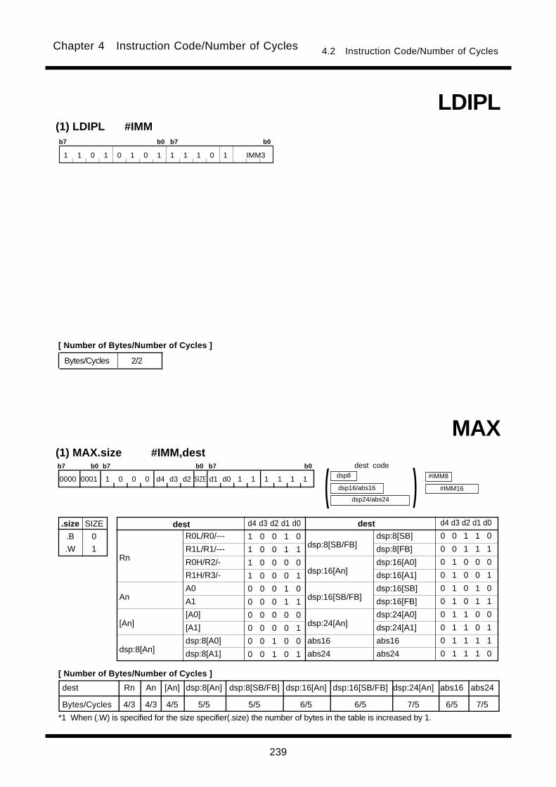
239
Chapter 4 Instruction Code/Number of Cycles 4.2 Instruction Code/Number of Cycles
(1) LDIPL #IMMb7 b0 b7 b0
1 1 0 1 0 1 0 1 1 1 1 0 1 IMM3
LDIPL
(1) MAX.size #IMM,dest
MAX
dest Rn An [An] dsp:8[An] dsp:8[SB/FB] dsp:16[An] dsp:16[SB/FB] dsp:24[An] abs16 abs24
Bytes/Cycles 4/3 4/3 4/5 5/5 5/5 6/5 6/5 7/5 6/5 7/5
.size
.B
.W
SIZE
0
1
R0L/R0/---
R1L/R1/---
R0H/R2/-
R1H/R3/-
A0
A1
[A0]
[A1]
dsp:8[A0]
dsp:8[A1]
dsp:8[SB/FB]
dsp:16[An]
dsp:16[SB/FB]
dsp:24[An]
abs16
abs24
Rn
An
[An]
dsp:8[An]
destdest d4 d3 d2 d1 d0
1 0 0 1 0
1 0 0 1 1
1 0 0 0 0
1 0 0 0 1
0 0 0 1 0
0 0 0 1 1
0 0 0 0 0
0 0 0 0 1
0 0 1 0 0
0 0 1 0 1
d4 d3 d2 d1 d0
0 0 1 1 0
0 0 1 1 1
0 1 0 0 0
0 1 0 0 1
0 1 0 1 0
0 1 0 1 1
0 1 1 0 0
0 1 1 0 1
0 1 1 1 1
0 1 1 1 0
dsp:8[SB]
dsp:8[FB]
dsp:16[A0]
dsp:16[A1]
dsp:16[SB]
dsp:16[FB]
dsp:24[A0]
dsp:24[A1]
abs16
abs24
Bytes/Cycles 2/2
dsp24/abs24
dsp8
dsp16/abs16 )( #IMM8
#IMM16
b7 b0 b7 b0 b7 b0
0000 0001 1 0 0 0 d4 d3 d2 SIZE d1 d0 1 1 1 1 1 1
[ Number of Bytes/Number of Cycles ]
dest code
*1 When (.W) is specified for the size specifier(.size) the number of bytes in the table is increased by 1.
[ Number of Bytes/Number of Cycles ]
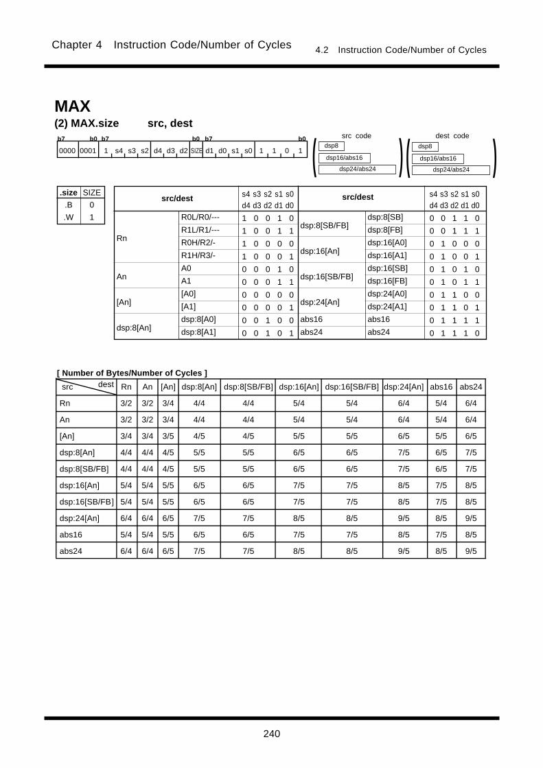
240
Chapter 4 Instruction Code/Number of Cycles 4.2 Instruction Code/Number of Cycles
src dest Rn An [An] dsp:8[An] dsp:8[SB/FB] dsp:16[An] dsp:16[SB/FB] dsp:24[An] abs16 abs24
Rn 3/2 3/2 3/4 4/4 4/4 5/4 5/4 6/4 5/4 6/4
An 3/2 3/2 3/4 4/4 4/4 5/4 5/4 6/4 5/4 6/4
[An] 3/4 3/4 3/5 4/5 4/5 5/5 5/5 6/5 5/5 6/5
dsp:8[An] 4/4 4/4 4/5 5/5 5/5 6/5 6/5 7/5 6/5 7/5
dsp:8[SB/FB] 4/4 4/4 4/5 5/5 5/5 6/5 6/5 7/5 6/5 7/5
dsp:16[An] 5/4 5/4 5/5 6/5 6/5 7/5 7/5 8/5 7/5 8/5
dsp:16[SB/FB] 5/4 5/4 5/5 6/5 6/5 7/5 7/5 8/5 7/5 8/5
dsp:24[An] 6/4 6/4 6/5 7/5 7/5 8/5 8/5 9/5 8/5 9/5
abs16 5/4 5/4 5/5 6/5 6/5 7/5 7/5 8/5 7/5 8/5
abs24 6/4 6/4 6/5 7/5 7/5 8/5 8/5 9/5 8/5 9/5
(2) MAX.size src, dest
dsp24/abs24
dsp8
dsp16/abs16 )( dsp24/abs24
dsp8
dsp16/abs16 )(MAX
b7 b0 b7 b0 b7 b0
0000 0001 1 s4 s3 s2 d4 d3 d2 SIZE d1 d0 s1 s0 1 1 0 1
.size
.B
.W
SIZE
0
1 R0L/R0/---
R1L/R1/---
R0H/R2/-
R1H/R3/-
A0
A1
[A0]
[A1]
dsp:8[A0]
dsp:8[A1]
dsp:8[SB/FB]
dsp:16[An]
dsp:16[SB/FB]
dsp:24[An]
abs16
abs24
Rn
An
[An]
dsp:8[An]
src/destsrc/dest s4 s3 s2 s1 s0d4 d3 d2 d1 d0
1 0 0 1 0
1 0 0 1 1
1 0 0 0 0
1 0 0 0 1
0 0 0 1 0
0 0 0 1 1
0 0 0 0 0
0 0 0 0 1
0 0 1 0 0
0 0 1 0 1
s4 s3 s2 s1 s0d4 d3 d2 d1 d0
0 0 1 1 0
0 0 1 1 1
0 1 0 0 0
0 1 0 0 1
0 1 0 1 0
0 1 0 1 1
0 1 1 0 0
0 1 1 0 1
0 1 1 1 1
0 1 1 1 0
dsp:8[SB]
dsp:8[FB]
dsp:16[A0]
dsp:16[A1]
dsp:16[SB]
dsp:16[FB]
dsp:24[A0]
dsp:24[A1]
abs16
abs24
dest codesrc code
[ Number of Bytes/Number of Cycles ]
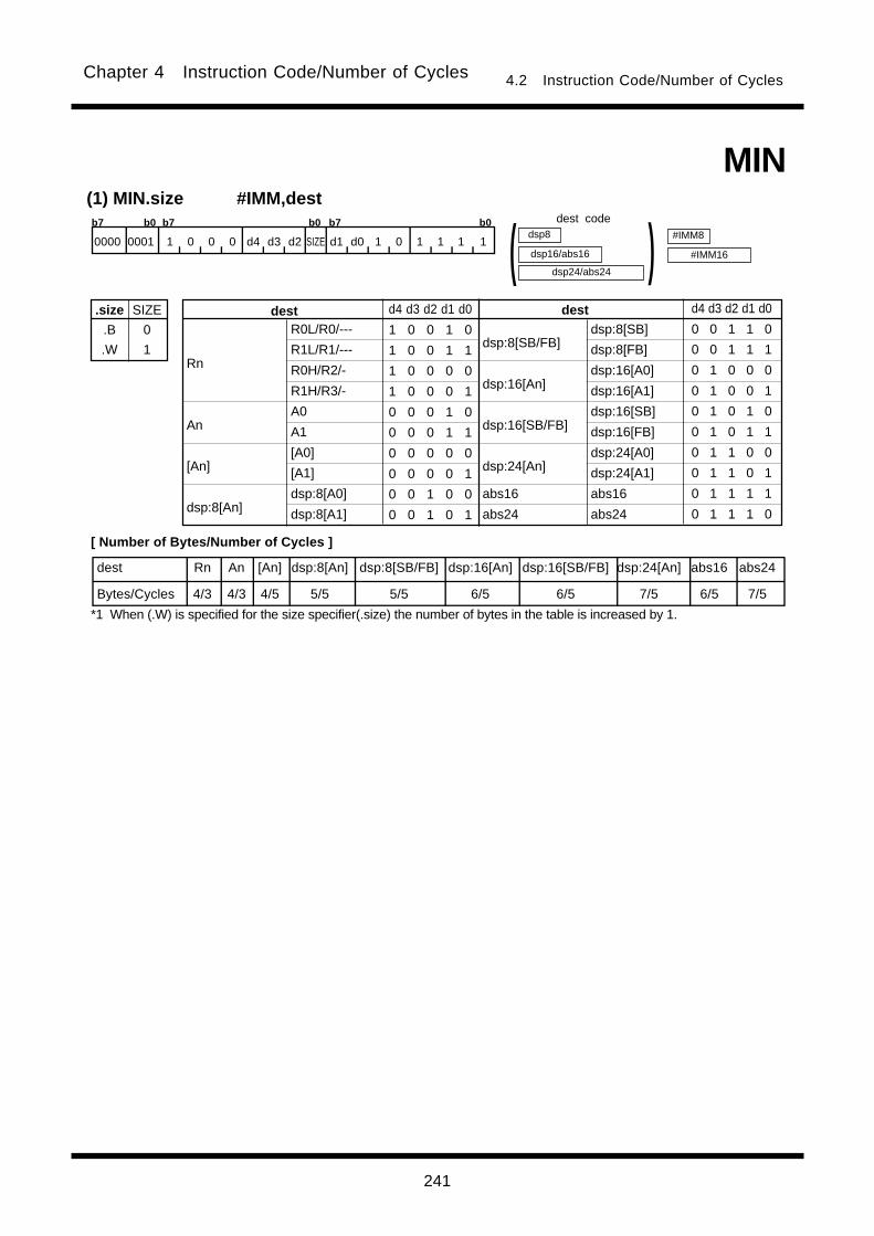
241
Chapter 4 Instruction Code/Number of Cycles 4.2 Instruction Code/Number of Cycles
(1) MIN.size #IMM,dest
MIN
dest Rn An [An] dsp:8[An] dsp:8[SB/FB] dsp:16[An] dsp:16[SB/FB] dsp:24[An] abs16 abs24
Bytes/Cycles 4/3 4/3 4/5 5/5 5/5 6/5 6/5 7/5 6/5 7/5
.size
.B
.W
SIZE
0
1
R0L/R0/---
R1L/R1/---
R0H/R2/-
R1H/R3/-
A0
A1
[A0]
[A1]
dsp:8[A0]
dsp:8[A1]
dsp:8[SB/FB]
dsp:16[An]
dsp:16[SB/FB]
dsp:24[An]
abs16
abs24
Rn
An
[An]
dsp:8[An]
destdest d4 d3 d2 d1 d0
1 0 0 1 0
1 0 0 1 1
1 0 0 0 0
1 0 0 0 1
0 0 0 1 0
0 0 0 1 1
0 0 0 0 0
0 0 0 0 1
0 0 1 0 0
0 0 1 0 1
d4 d3 d2 d1 d0
0 0 1 1 0
0 0 1 1 1
0 1 0 0 0
0 1 0 0 1
0 1 0 1 0
0 1 0 1 1
0 1 1 0 0
0 1 1 0 1
0 1 1 1 1
0 1 1 1 0
dsp:8[SB]
dsp:8[FB]
dsp:16[A0]
dsp:16[A1]
dsp:16[SB]
dsp:16[FB]
dsp:24[A0]
dsp:24[A1]
abs16
abs24
dsp24/abs24
dsp8
dsp16/abs16 )( #IMM8
#IMM16
b7 b0 b7 b0 b7 b0
0000 0001 1 0 0 0 d4 d3 d2 SIZE d1 d0 1 0 1 1 1 1
dest code
[ Number of Bytes/Number of Cycles ]
*1 When (.W) is specified for the size specifier(.size) the number of bytes in the table is increased by 1.

242
Chapter 4 Instruction Code/Number of Cycles 4.2 Instruction Code/Number of Cycles
src dest Rn An [An] dsp:8[An] dsp:8[SB/FB] dsp:16[An] dsp:16[SB/FB] dsp:24[An] abs16 abs24
Rn 3/2 3/2 3/4 4/4 4/4 5/4 5/4 6/4 5/4 6/4
An 3/2 3/2 3/4 4/4 4/4 5/4 5/4 6/4 5/4 6/4
[An] 3/4 3/4 3/5 4/5 4/5 5/5 5/5 6/5 5/5 6/5
dsp:8[An] 4/4 4/4 4/5 5/5 5/5 6/5 6/5 7/5 6/5 7/5
dsp:8[SB/FB] 4/4 4/4 4/5 5/5 5/5 6/5 6/5 7/5 6/5 7/5
dsp:16[An] 5/4 5/4 5/5 6/5 6/5 7/5 7/5 8/5 7/5 8/5
dsp:16[SB/FB] 5/4 5/4 5/5 6/5 6/5 7/5 7/5 8/5 7/5 8/5
dsp:24[An] 6/4 6/4 6/5 7/5 7/5 8/5 8/5 9/5 8/5 9/5
abs16 5/4 5/4 5/5 6/5 6/5 7/5 7/5 8/5 7/5 8/5
abs24 6/4 6/4 6/5 7/5 7/5 8/5 8/5 9/5 8/5 9/5
(2) MIN.size src, dest
dsp24/abs24
dsp8
dsp16/abs16 )( dsp24/abs24
dsp8
dsp16/abs16 )(MIN
b7 b0 b7 b0 b7 b0
.size
.B
.W
SIZE
0
1 R0L/R0/---
R1L/R1/---
R0H/R2/-
R1H/R3/-
A0
A1
[A0]
[A1]
dsp:8[A0]
dsp:8[A1]
dsp:8[SB/FB]
dsp:16[An]
dsp:16[SB/FB]
dsp:24[An]
abs16
abs24
Rn
An
[An]
dsp:8[An]
src/destsrc/dest s4 s3 s2 s1 s0d4 d3 d2 d1 d0
1 0 0 1 0
1 0 0 1 1
1 0 0 0 0
1 0 0 0 1
0 0 0 1 0
0 0 0 1 1
0 0 0 0 0
0 0 0 0 1
0 0 1 0 0
0 0 1 0 1
s4 s3 s2 s1 s0d4 d3 d2 d1 d0
0 0 1 1 0
0 0 1 1 1
0 1 0 0 0
0 1 0 0 1
0 1 0 1 0
0 1 0 1 1
0 1 1 0 0
0 1 1 0 1
0 1 1 1 1
0 1 1 1 0
dsp:8[SB]
dsp:8[FB]
dsp:16[A0]
dsp:16[A1]
dsp:16[SB]
dsp:16[FB]
dsp:24[A0]
dsp:24[A1]
abs16
abs24
0000 0001 1 s4 s3 s2 d4 d3 d2 SIZE d1 d0 s1 s0 1 1 0 0
dest codesrc code
[ Number of Bytes/Number of Cycles ]
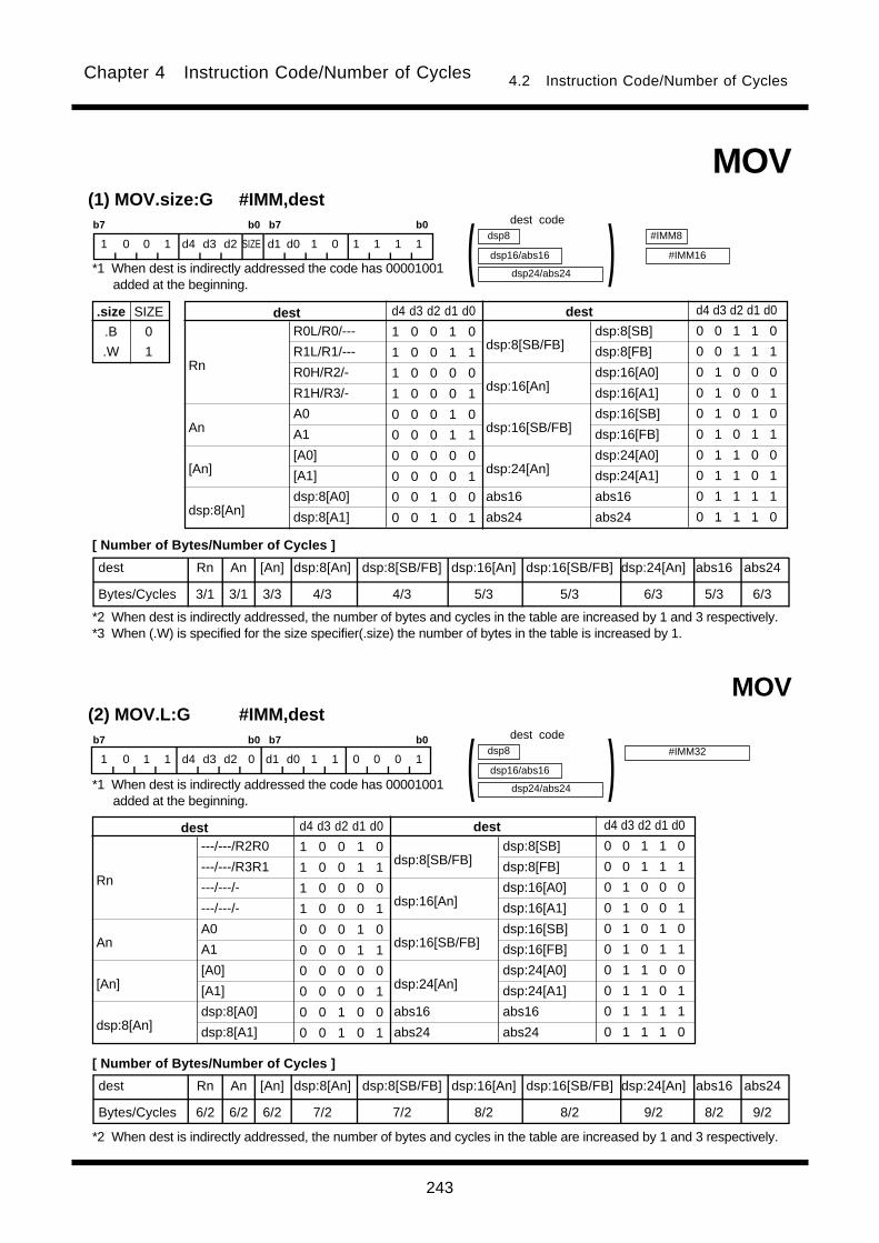
243
Chapter 4 Instruction Code/Number of Cycles 4.2 Instruction Code/Number of Cycles
(1) MOV.size:G #IMM,dest
.size
.B
.W
SIZE
0
1
b7 b0 b7 b0
1 0 0 1 d4 d3 d2 SIZE d1 d0 1 0 1 1 1 1
R0L/R0/---
R1L/R1/---
R0H/R2/-
R1H/R3/-
A0
A1
[A0]
[A1]
dsp:8[A0]
dsp:8[A1]
dsp:8[SB/FB]
dsp:16[An]
dsp:16[SB/FB]
dsp:24[An]
abs16
abs24
Rn
An
[An]
dsp:8[An]
destdest d4 d3 d2 d1 d0
1 0 0 1 0
1 0 0 1 1
1 0 0 0 0
1 0 0 0 1
0 0 0 1 0
0 0 0 1 1
0 0 0 0 0
0 0 0 0 1
0 0 1 0 0
0 0 1 0 1
d4 d3 d2 d1 d0
0 0 1 1 0
0 0 1 1 1
0 1 0 0 0
0 1 0 0 1
0 1 0 1 0
0 1 0 1 1
0 1 1 0 0
0 1 1 0 1
0 1 1 1 1
0 1 1 1 0
dsp24/abs24
dsp8
dsp16/abs16 )(dsp:8[SB]
dsp:8[FB]
dsp:16[A0]
dsp:16[A1]
dsp:16[SB]
dsp:16[FB]
dsp:24[A0]
dsp:24[A1]
abs16
abs24
#IMM8
#IMM16
MOV
(2) MOV.L:G #IMM,destb7 b0 b7 b0
1 0 1 1 d4 d3 d2 0 d1 d0 1 1 0 0 0 1
---/---/R2R0
---/---/R3R1
---/---/-
---/---/-
A0
A1
[A0]
[A1]
dsp:8[A0]
dsp:8[A1]
dsp:8[SB/FB]
dsp:16[An]
dsp:16[SB/FB]
dsp:24[An]
abs16
abs24
Rn
An
[An]
dsp:8[An]
destdest d4 d3 d2 d1 d0
1 0 0 1 0
1 0 0 1 1
1 0 0 0 0
1 0 0 0 1
0 0 0 1 0
0 0 0 1 1
0 0 0 0 0
0 0 0 0 1
0 0 1 0 0
0 0 1 0 1
d4 d3 d2 d1 d0
0 0 1 1 0
0 0 1 1 1
0 1 0 0 0
0 1 0 0 1
0 1 0 1 0
0 1 0 1 1
0 1 1 0 0
0 1 1 0 1
0 1 1 1 1
0 1 1 1 0
dsp24/abs24
dsp8
dsp16/abs16 )(dsp:8[SB]
dsp:8[FB]
dsp:16[A0]
dsp:16[A1]
dsp:16[SB]
dsp:16[FB]
dsp:24[A0]
dsp:24[A1]
abs16
abs24
MOV
#IMM32
dest Rn An [An] dsp:8[An] dsp:8[SB/FB] dsp:16[An] dsp:16[SB/FB] dsp:24[An] abs16 abs24
Bytes/Cycles 3/1 3/1 3/3 4/3 4/3 5/3 5/3 6/3 5/3 6/3
dest Rn An [An] dsp:8[An] dsp:8[SB/FB] dsp:16[An] dsp:16[SB/FB] dsp:24[An] abs16 abs24
Bytes/Cycles 6/2 6/2 6/2 7/2 7/2 8/2 8/2 9/2 8/2 9/2
dest code
*1 When dest is indirectly addressed the code has 00001001added at the beginning.
[ Number of Bytes/Number of Cycles ]
*2 When dest is indirectly addressed, the number of bytes and cycles in the table are increased by 1 and 3 respectively.*3 When (.W) is specified for the size specifier(.size) the number of bytes in the table is increased by 1.
dest code
*1 When dest is indirectly addressed the code has 00001001added at the beginning.
[ Number of Bytes/Number of Cycles ]
*2 When dest is indirectly addressed, the number of bytes and cycles in the table are increased by 1 and 3 respectively.
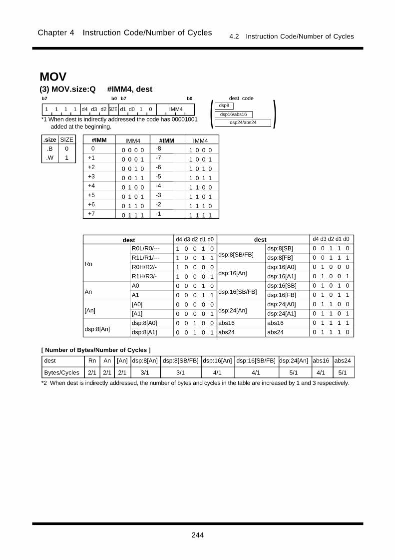
244
Chapter 4 Instruction Code/Number of Cycles 4.2 Instruction Code/Number of Cycles
(3) MOV.size:Q #IMM4, destb7 b0 b7 b0
1 1 1 1 d4 d3 d2 SIZE d1 d0 1 0 IMM4
dest Rn An [An] dsp:8[An] dsp:8[SB/FB] dsp:16[An] dsp:16[SB/FB] dsp:24[An] abs16 abs24
Bytes/Cycles 2/1 2/1 2/1 3/1 3/1 4/1 4/1 5/1 4/1 5/1
0
+1
+2
+3
+4
+5
+6
+7
#IMM#IMM IMM4
0 0 0 0
0 0 0 1
0 0 1 0
0 0 1 1
0 1 0 0
0 1 0 1
0 1 1 0
0 1 1 1
IMM4
1 0 0 0
1 0 0 1
1 0 1 0
1 0 1 1
1 1 0 0
1 1 0 1
1 1 1 0
1 1 1 1
dsp24/abs24
dsp8
dsp16/abs16 )(MOV
R0L/R0/---
R1L/R1/---
R0H/R2/-
R1H/R3/-
A0
A1
[A0]
[A1]
dsp:8[A0]
dsp:8[A1]
dsp:8[SB/FB]
dsp:16[An]
dsp:16[SB/FB]
dsp:24[An]
abs16
abs24
Rn
An
[An]
dsp:8[An]
destdest d4 d3 d2 d1 d0
1 0 0 1 0
1 0 0 1 1
1 0 0 0 0
1 0 0 0 1
0 0 0 1 0
0 0 0 1 1
0 0 0 0 0
0 0 0 0 1
0 0 1 0 0
0 0 1 0 1
d4 d3 d2 d1 d0
0 0 1 1 0
0 0 1 1 1
0 1 0 0 0
0 1 0 0 1
0 1 0 1 0
0 1 0 1 1
0 1 1 0 0
0 1 1 0 1
0 1 1 1 1
0 1 1 1 0
dsp:8[SB]
dsp:8[FB]
dsp:16[A0]
dsp:16[A1]
dsp:16[SB]
dsp:16[FB]
dsp:24[A0]
dsp:24[A1]
abs16
abs24
-8
-7
-6
-5
-4
-3
-2
-1
.size
.B
.W
SIZE
0
1
dest code
*1 When dest is indirectly addressed the code has 00001001added at the beginning.
[ Number of Bytes/Number of Cycles ]
*2 When dest is indirectly addressed, the number of bytes and cycles in the table are increased by 1 and 3 respectively.
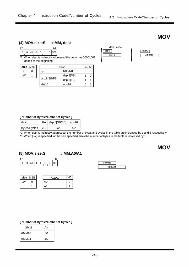
245
Chapter 4 Instruction Code/Number of Cycles 4.2 Instruction Code/Number of Cycles
dest Rn dsp:8[SB/FB] abs16
Bytes/Cycles 2/1 3/2 4/2
(4) MOV.size:S #IMM, dest
.size
.B
.W
SIZE
0
1
b7 b0
0 0 d1 d0 0 1 0 SIZE
R0L/R0
dsp:8[SB]
dsp:8[FB]
abs16
Rn
dsp:8[SB/FB]
abs16
dest d1 d0
0 0
1 0
1 1
0 1
#IMM8
#IMM16
dsp8
abs16 )(MOV
1 0 SIZE 1 1 1 0 d0
(5) MOV.size:S #IMM,A0/A1b7 b0
#IMM An
#IMM16 3/1
#IMM24 4/2
A0
A1
A0/A1 d0
0
1
#IMM16
#IMM24
MOV
.size
.W
.L
SIZE
0
1
dest code
*1 When dest is indirectly addressed the code has 00001001added at the beginning.
[ Number of Bytes/Number of Cycles ]
*2 When dest is indirectly addressed, the number of bytes and cycles in the table are increased by 1 and 3 respectively.*3 When (.W) is specified for the size specifier(.size) the number of bytes in the table is increased by 1.
[ Number of Bytes/Number of Cycles ]

246
Chapter 4 Instruction Code/Number of Cycles 4.2 Instruction Code/Number of Cycles
dest Rn dsp:8[SB/FB] abs16
Bytes/Cycles 1/1 2/1 3/1
(6) MOV.size:Z #0, dest
.size
.B
.W
SIZE
0
1
b7 b0
0 0 d1 d0 0 0 1 SIZE
R0L/R0
dsp:8[SB]
dsp:8[FB]
abs16
Rn
dsp:8[SB/FB]
abs16
dest d1 d0
0 0
1 0
1 1
0 1
dsp8
abs16 )(MOV
dest code
*1 When dest is indirectly addressed the code has 00001001added at the beginning.
[ Number of Bytes/Number of Cycles ]
*2 When dest is indirectly addressed, the number of bytes and cycles in the table are increased by 1 and 3 respectively.

247
Chapter 4 Instruction Code/Number of Cycles 4.2 Instruction Code/Number of Cycles
src dest Rn An [An] dsp:8[An] dsp:8[SB/FB] dsp:16[An] dsp:16[SB/FB] dsp:24[An] abs16 abs24
Rn 2/1 2/1 2/1 3/1 3/1 4/1 4/1 5/1 4/1 5/1
An 2/1 2/1 2/1 3/1 3/1 4/1 4/1 5/1 4/1 5/1
[An] 2/3 2/3 2/3 3/2 3/2 4/2 4/2 5/2 4/2 5/2
dsp:8[An] 3/3 3/3 3/3 4/2 4/2 5/2 5/2 6/2 5/2 6/2
dsp:8[SB/FB] 3/3 3/3 3/3 4/2 4/2 5/2 5/2 6/2 5/2 6/2
dsp:16[An] 4/3 4/3 4/3 5/2 5/2 6/2 6/2 7/2 6/2 7/2
dsp:16[SB/FB] 4/3 4/3 4/3 5/2 5/2 6/2 6/2 7/2 6/2 7/2
dsp:24[An] 5/3 5/3 5/3 6/2 6/2 7/2 7/2 8/2 7/2 8/2
abs16 4/3 4/3 4/3 5/2 5/2 6/2 6/2 7/2 6/2 7/2
abs24 5/3 5/3 5/3 6/2 6/2 7/2 7/2 8/2 7/2 8/2
(7) MOV.size:G src, dest
.size
.B
.W
SIZE
0
1
b7 b0 b7 b0
1 s4 s3 s2 d4 d3 d2 SIZE d1 d0 s1 s0 1 0 1 1
R0L/R0/---
R1L/R1/---
R0H/R2/-
R1H/R3/-
A0
A1
[A0]
[A1]
dsp:8[A0]
dsp:8[A1]
dsp:8[SB/FB]
dsp:16[An]
dsp:16[SB/FB]
dsp:24[An]
abs16
abs24
Rn
An
[An]
dsp:8[An]
src/destsrc/dest s4 s3 s2 s1 s0d4 d3 d2 d1 d0
1 0 0 1 0
1 0 0 1 1
1 0 0 0 0
1 0 0 0 1
0 0 0 1 0
0 0 0 1 1
0 0 0 0 0
0 0 0 0 1
0 0 1 0 0
0 0 1 0 1
s4 s3 s2 s1 s0d4 d3 d2 d1 d0
0 0 1 1 0
0 0 1 1 1
0 1 0 0 0
0 1 0 0 1
0 1 0 1 0
0 1 0 1 1
0 1 1 0 0
0 1 1 0 1
0 1 1 1 1
0 1 1 1 0
dsp24/abs24
dsp8
dsp16/abs16 )(
dsp:8[SB]
dsp:8[FB]
dsp:16[A0]
dsp:16[A1]
dsp:16[SB]
dsp:16[FB]
dsp:24[A0]
dsp:24[A1]
abs16
abs24
dsp24/abs24
dsp8
dsp16/abs16 )(MOV
dest codesrc code
*1 For indirect addressing, the following number is added atthe beginning of code:
01000001 when src is indirectly addressed00001001 when dest is indirectly addressed01001001 when src and dest are indirectly addressed
[ Number of Bytes/Number of Cycles ]
*2 When src or dest is indirectly addressed, the number of bytes and cycles in the table are increased by 1 and 3,respectively. Also, when src and dest both are indirectly addressed, the number of bytes and cycles in the table areincreased by 1 and 6, respectively.

248
Chapter 4 Instruction Code/Number of Cycles 4.2 Instruction Code/Number of Cycles
src dest Rn An [An] dsp:8[An] dsp:8[SB/FB] dsp:16[An] dsp:16[SB/FB] dsp:24[An] abs16 abs24
Rn 2/2 2/2 2/2 3/2 3/2 4/2 4/2 5/2 4/2 5/2
An 2/2 2/2 2/2 3/2 3/2 4/2 4/2 5/2 4/2 5/2
[An] 2/4 2/4 2/4 3/4 3/4 4/4 4/4 5/4 4/4 5/4
dsp:8[An] 3/4 3/4 3/4 4/4 4/4 5/4 5/4 6/4 5/4 6/4
dsp:8[SB/FB] 3/4 3/4 3/4 4/4 4/4 5/4 5/4 6/4 5/4 6/4
dsp:16[An] 4/4 4/4 4/4 5/4 5/4 6/4 6/4 7/4 6/4 7/4
dsp:16[SB/FB] 4/4 4/4 4/4 5/4 5/4 6/4 6/4 7/4 6/4 7/4
dsp:24[An] 5/4 5/4 5/4 6/4 6/4 7/4 7/4 8/4 7/4 8/4
abs16 4/4 4/4 4/4 5/4 5/4 6/4 6/4 7/4 6/4 7/4
abs24 5/4 5/4 5/4 6/4 6/4 7/4 7/4 8/4 7/4 8/4
(8) MOV.L:G src, destb7 b0 b7 b0
1 s4 s3 s2 d4 d3 d2 1 d1 d0 s1 s0 0 0 1 1
---/---/R2R0
---/---/R3R1
---/---/-
---/---/-
A0
A1
[A0]
[A1]
dsp:8[A0]
dsp:8[A1]
dsp:8[SB/FB]
dsp:16[An]
dsp:16[SB/FB]
dsp:24[An]
abs16
abs24
Rn
An
[An]
dsp:8[An]
src/destsrc/dest s4 s3 s2 s1 s0d4 d3 d2 d1 d0
1 0 0 1 0
1 0 0 1 1
1 0 0 0 0
1 0 0 0 1
0 0 0 1 0
0 0 0 1 1
0 0 0 0 0
0 0 0 0 1
0 0 1 0 0
0 0 1 0 1
s4 s3 s2 s1 s0d4 d3 d2 d1 d0
0 0 1 1 0
0 0 1 1 1
0 1 0 0 0
0 1 0 0 1
0 1 0 1 0
0 1 0 1 1
0 1 1 0 0
0 1 1 0 1
0 1 1 1 1
0 1 1 1 0
dsp24/abs24
dsp8
dsp16/abs16 )(
dsp:8[SB]
dsp:8[FB]
dsp:16[A0]
dsp:16[A1]
dsp:16[SB]
dsp:16[FB]
dsp:24[A0]
dsp:24[A1]
abs16
abs24
dsp24/abs24
dsp8
dsp16/abs16 )(MOV
dest codesrc code
*1 For indirect addressing, the following number is added atthe beginning of code:
01000001 when src is indirectly addressed00001001 when dest is indirectly addressed01001001 when src and dest are indirectly addressed
[ Number of Bytes/Number of Cycles ]
*2 When src or dest is indirectly addressed, the number of bytes and cycles in the table are increased by 1 and 3respectively. Also, when src and dest both are indirectly addressed, the number of bytes and cycles in the table areincreased by 1 and 6, respectively.

249
Chapter 4 Instruction Code/Number of Cycles 4.2 Instruction Code/Number of Cycles
MOV(9) MOV.size:S src, R0L/R0b7 b0
0 0 s1 s0 1 0 0 SIZEdsp8
abs16 )(
src dsp:8[SB/FB] abs16
Bytes/Cycles 2/2 3/2
.size
.B
.W
SIZE
0
1
dsp:8[SB]
dsp:8[FB]
abs16
dsp:8[SB/FB]
abs16
src s1 s0
1 0
1 1
0 1
MOV(10) MOV.size:S src, R1L/R1b7 b0
0 1 s1 s0 1 1 1 SIZEdsp8
abs16 )(
src Rn dsp:8[SB/FB] abs16
Bytes/Cycles 1/3 2/3 3/3
.size
.B
.W
SIZE
0
1
R0L/R0
dsp:8[SB]
dsp:8[FB]
abs16
Rn
dsp:8[SB/FB]
abs16
src s1 s0
0 0
1 0
1 1
0 1
src code
*1 When src is indirectly addressed the code has 00001001added at the beginning.
[ Number of Bytes/Number of Cycles ]
*2 When src is indirectly addressed, the number of bytes and cycles in the table are increased by 1 and 3 respectively.
src code
*1 When src is indirectly addressed the code has 00001001added at the beginning.
[ Number of Bytes/Number of Cycles ]
*2 When src is indirectly addressed, the number of bytes and cycles in the table are increased by 1 and 3, respectively.
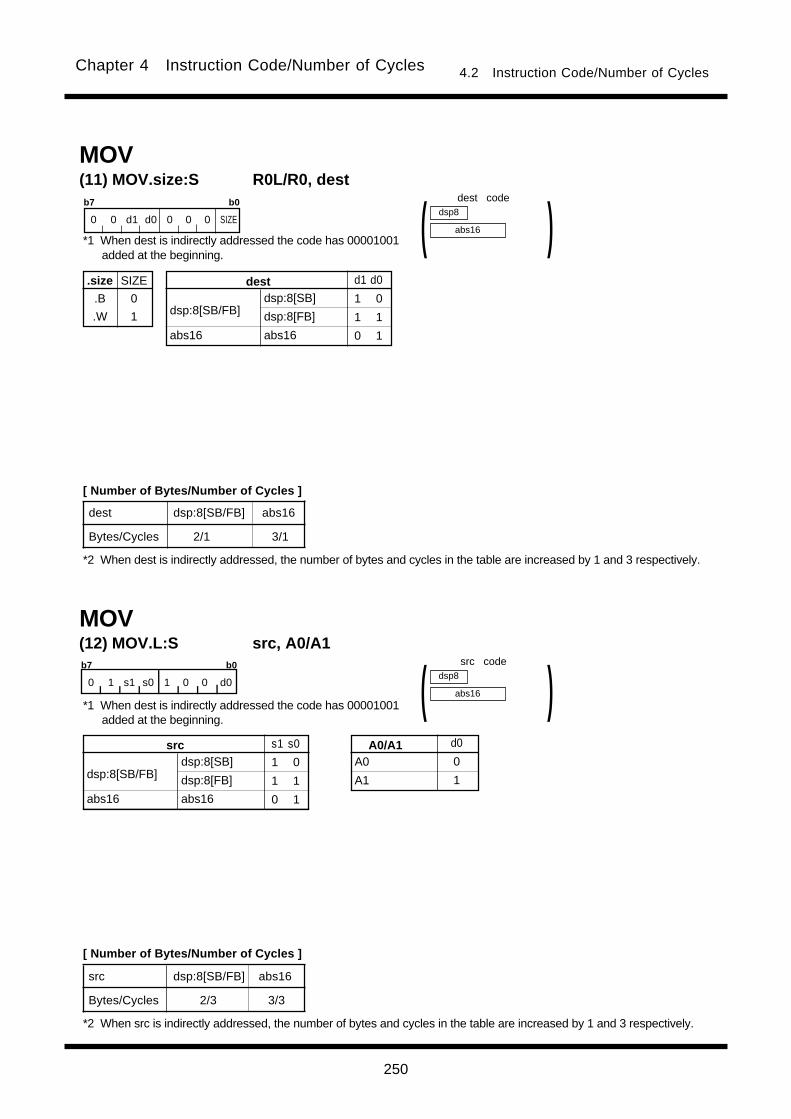
250
Chapter 4 Instruction Code/Number of Cycles 4.2 Instruction Code/Number of Cycles
MOV(12) MOV.L:S src, A0/A1b7 b0
0 1 s1 s0 1 0 0 d0dsp8
abs16 )(
src dsp:8[SB/FB] abs16
Bytes/Cycles 2/3 3/3
dsp:8[SB]
dsp:8[FB]
abs16
dsp:8[SB/FB]
abs16
src s1 s0
1 0
1 1
0 1
A0
A1
A0/A1 d0
0
1
(11) MOV.size:S R0L/R0, destb7 b0
0 0 d1 d0 0 0 0 SIZEdsp8
abs16 )(MOV
dest dsp:8[SB/FB] abs16
Bytes/Cycles 2/1 3/1
.size
.B
.W
SIZE
0
1
dsp:8[SB]
dsp:8[FB]
abs16
dsp:8[SB/FB]
abs16
dest d1 d0
1 0
1 1
0 1
dest code
*1 When dest is indirectly addressed the code has 00001001added at the beginning.
[ Number of Bytes/Number of Cycles ]
*2 When dest is indirectly addressed, the number of bytes and cycles in the table are increased by 1 and 3 respectively.
src code
[ Number of Bytes/Number of Cycles ]
*2 When src is indirectly addressed, the number of bytes and cycles in the table are increased by 1 and 3 respectively.
*1 When dest is indirectly addressed the code has 00001001added at the beginning.

251
Chapter 4 Instruction Code/Number of Cycles 4.2 Instruction Code/Number of Cycles
(13) MOV.size:G dsp:8[SP], dest
.size
.B
.W
SIZE
0
1
b7 b0 b7 b0
1 0 1 1 d4 d3 d2 SIZE d1 d0 0 0 1 1 1 1
R0L/R0/---
R1L/R1/---
R0H/R2/-
R1H/R3/-
A0
A1
[A0]
[A1]
dsp:8[A0]
dsp:8[A1]
dsp:8[SB/FB]
dsp:16[An]
dsp:16[SB/FB]
dsp:24[An]
abs16
abs24
Rn
An
[An]
dsp:8[An]
destdest d4 d3 d2 d1 d0
1 0 0 1 0
1 0 0 1 1
1 0 0 0 0
1 0 0 0 1
0 0 0 1 0
0 0 0 1 1
0 0 0 0 0
0 0 0 0 1
0 0 1 0 0
0 0 1 0 1
d4 d3 d2 d1 d0
0 0 1 1 0
0 0 1 1 1
0 1 0 0 0
0 1 0 0 1
0 1 0 1 0
0 1 0 1 1
0 1 1 0 0
0 1 1 0 1
0 1 1 1 1
0 1 1 1 0
dsp24/abs24
dsp8
dsp16/abs16 )(dsp:8[SB]
dsp:8[FB]
dsp:16[A0]
dsp:16[A1]
dsp:16[SB]
dsp:16[FB]
dsp:24[A0]
dsp:24[A1]
abs16
abs24
dsp8
MOV
dest Rn An [An] dsp:8[An] dsp:8[SB/FB] dsp:16[An] dsp:16[SB/FB] dsp:24[An] abs16 abs24
Bytes/Cycles 3/3 3/3 3/3 4/3 4/3 5/3 5/3 6/3 5/3 6/3
(14) MOV.size:G src, dsp:8[SP]b7 b0 b7 b0
1 0 1 0 s4 s3 s2 SIZE s1 s0 0 0 1 1 1 1
R0L/R0/---
R1L/R1/---
R0H/R2/-
R1H/R3/-
A0
A1
[A0]
[A1]
dsp:8[A0]
dsp:8[A1]
dsp:8[SB/FB]
dsp:16[An]
dsp:16[SB/FB]
dsp:24[An]
abs16
abs24
Rn
An
[An]
dsp:8[An]
srcsrc s4 s3 s2 s1 s0
1 0 0 1 0
1 0 0 1 1
1 0 0 0 0
1 0 0 0 1
0 0 0 1 0
0 0 0 1 1
0 0 0 0 0
0 0 0 0 1
0 0 1 0 0
0 0 1 0 1
s4 s3 s2 s1 s0
0 0 1 1 0
0 0 1 1 1
0 1 0 0 0
0 1 0 0 1
0 1 0 1 0
0 1 0 1 1
0 1 1 0 0
0 1 1 0 1
0 1 1 1 1
0 1 1 1 0
dsp24/abs24
dsp8
dsp16/abs16 )(dsp:8[SB]
dsp:8[FB]
dsp:16[A0]
dsp:16[A1]
dsp:16[SB]
dsp:16[FB]
dsp:24[A0]
dsp:24[A1]
abs16
abs24
MOV
src Rn An [An] dsp:8[An] dsp:8[SB/FB] dsp:16[An] dsp:16[SB/FB] dsp:24[An] abs16 abs24
Bytes/Cycles 3/3 3/3 3/3 4/3 4/3 5/3 5/3 6/3 5/3 6/3
dsp8
.size
.B
.W
SIZE
0
1
src code dest code
[ Number of Bytes/Number of Cycles ]
dest codesrc code
[ Number of Bytes/Number of Cycles ]

252
Chapter 4 Instruction Code/Number of Cycles 4.2 Instruction Code/Number of Cycles
b7 b0 b7 b0
1 1 0 1 s4 s3 s2 1 s1 s0 0 1 1 DEST
dsp24/abs24
dsp8
dsp16/abs16 )((1) MOVA src, dest
MOVA
dsp:16[SB]
dsp:16[FB]
dsp:24[A0]
dsp:24[A1]
abs16
abs24
dsp:8[A0]
dsp:8[A1]
dsp:8[SB]
dsp:8[FB]
dsp:16[A0]
dsp:16[A1]
dsp:16[SB/FB]
dsp:24[An]
abs16
abs24
dsp:8[An]
dsp:8[SB/FB]
dsp:16[An]
srcsrc s4 s3 s2 s1 s0
0 0 1 0 0
0 0 1 0 1
0 0 1 1 0
0 0 1 1 1
0 1 0 0 0
0 1 0 0 1
s4 s3 s2 s1 s0
0 1 0 1 0
0 1 0 1 1
0 1 1 0 0
0 1 1 0 1
0 1 1 1 1
0 1 1 1 0
R2R0
R3R1
A0
A1
dest DEST
0 0 0
0 0 1
0 1 0
0 1 1
src code
[ Number of Bytes/Number of Cycles ]
src dsp:8[An] dsp:8[SB/FB] dsp:16[An] dsp:16[SB/FB] dsp:24[An] abs16 abs24
Bytes/Cycles 3/2 3/2 4/2 4/2 5/2 4/2 5/2

253
Chapter 4 Instruction Code/Number of Cycles 4.2 Instruction Code/Number of Cycles
LL
HL
LH
HH
Dir o3 o2 o1 o0
0 1 0 0
0 1 0 1
0 1 1 0
0 1 1 1
MOVDir(1) MOVDir R0L, dest
Rn An [An] dsp:8[An] dsp:8[SB/FB] dsp:16[An] dsp:16[SB/FB] dsp:24[An] abs16 abs24
3/3 3/3 3/5 4/5 4/5 5/5 5/5 6/5 5/5 6/5
3/6 3/6 3/8 4/8 4/8 5/8 5/8 6/8 5/8 6/8
R0L/---/---
R1L/---/---
R0H/---/-
R1H/---/-
---
---
[A0]
[A1]
dsp:8[A0]
dsp:8[A1]
dsp:8[SB/FB]
dsp:16[An]
dsp:16[SB/FB]
dsp:24[An]
abs16
abs24
Rn
An
[An]
dsp:8[An]
destdest d4 d3 d2 d1 d0
1 0 0 1 0
1 0 0 1 1
1 0 0 0 0
1 0 0 0 1
0 0 0 1 0
0 0 0 1 1
0 0 0 0 0
0 0 0 0 1
0 0 1 0 0
0 0 1 0 1
d4 d3 d2 d1 d0
0 0 1 1 0
0 0 1 1 1
0 1 0 0 0
0 1 0 0 1
0 1 0 1 0
0 1 0 1 1
0 1 1 0 0
0 1 1 0 1
0 1 1 1 1
0 1 1 1 0
dsp:8[SB]
dsp:8[FB]
dsp:16[A0]
dsp:16[A1]
dsp:16[SB]
dsp:16[FB]
dsp:24[A0]
dsp:24[A1]
abs16
abs24
dsp24/abs24
dsp8
dsp16/abs16 )(b7 b0 b7 b0 b7 b0
0000 0001 1 0 1 o2 d4 d3 d2 0 d1 d0 o1 o0 1 1 1 o3
dest
MOVHH,
MOVLL
MOVHL,
MOVLH
dest code
[ Number of Bytes/Number of Cycles ]

254
Chapter 4 Instruction Code/Number of Cycles 4.2 Instruction Code/Number of Cycles
MOVDir(2) MOVDir src, R0L
R0L/---/---
R1L/---/---
R0H/---/-
R1H/---/-
---
---
[A0]
[A1]
dsp:8[A0]
dsp:8[A1]
dsp:8[SB/FB]
dsp:16[An]
dsp:16[SB/FB]
dsp:24[An]
abs16
abs24
Rn
An
[An]
dsp:8[An]
srcsrc s4 s3 s2 s1 s0
1 0 0 1 0
1 0 0 1 1
1 0 0 0 0
1 0 0 0 1
0 0 0 1 0
0 0 0 1 1
0 0 0 0 0
0 0 0 0 1
0 0 1 0 0
0 0 1 0 1
s4 s3 s2 s1 s0
0 0 1 1 0
0 0 1 1 1
0 1 0 0 0
0 1 0 0 1
0 1 0 1 0
0 1 0 1 1
0 1 1 0 0
0 1 1 0 1
0 1 1 1 1
0 1 1 1 0
dsp:8[SB]
dsp:8[FB]
dsp:16[A0]
dsp:16[A1]
dsp:16[SB]
dsp:16[FB]
dsp:24[A0]
dsp:24[A1]
abs16
abs24
dsp24/abs24
dsp8
dsp16/abs16 )(b7 b0 b7 b0 b7 b0
LL
HL
LH
HH
Dir o3 o2 o1 o0
0 0 0 0
0 0 0 1
0 0 1 0
0 0 1 1
src code
[ Number of Bytes/Number of Cycles ]
Rn An [An] dsp:8[An] dsp:8[SB/FB] dsp:16[An] dsp:16[SB/FB] dsp:24[An] abs16 abs24
3/3 3/3 3/5 4/5 4/5 5/5 5/5 6/5 5/5 6/5
3/6 3/6 3/8 4/8 4/8 5/8 5/8 6/8 5/8 6/8
dest
MOVHH,
MOVLL
MOVHL,
MOVLH
0000 0001 1 0 1 o2 s4 s3 s2 0 s1 s0 o1 o0 1 1 1 o3

255
Chapter 4 Instruction Code/Number of Cycles 4.2 Instruction Code/Number of Cycles
(1) MOVX #IMM, destb7 b0 b7 b0
1 0 1 1 d4 d3 d2 0 d1 d0 0 1 0 0 0 1
dest Rn An [An] dsp:8[An] dsp:8[SB/FB] dsp:16[An] dsp:16[SB/FB] dsp:24[An] abs16 abs24
Bytes/Cycles 3/2 3/2 3/2 4/2 4/2 5/2 5/2 6/2 5/2 6/2
---/---/R2R0
---/---/R3R1
---/---/-
---/---/-
A0
A1
[A0]
[A1]
dsp:8[A0]
dsp:8[A1]
dsp:8[SB/FB]
dsp:16[An]
dsp:16[SB/FB]
dsp:24[An]
abs16
abs24
Rn
An
[An]
dsp:8[An]
destdest d4 d3 d2 d1 d0
1 0 0 1 0
1 0 0 1 1
1 0 0 0 0
1 0 0 0 1
0 0 0 1 0
0 0 0 1 1
0 0 0 0 0
0 0 0 0 1
0 0 1 0 0
0 0 1 0 1
d4 d3 d2 d1 d0
0 0 1 1 0
0 0 1 1 1
0 1 0 0 0
0 1 0 0 1
0 1 0 1 0
0 1 0 1 1
0 1 1 0 0
0 1 1 0 1
0 1 1 1 1
0 1 1 1 0
dsp24/abs24
dsp8
dsp16/abs16 )(dsp:8[SB]
dsp:8[FB]
dsp:16[A0]
dsp:16[A1]
dsp:16[SB]
dsp:16[FB]
dsp:24[A0]
dsp:24[A1]
abs16
abs24
#IMM8
MOVX
(1) MUL.size #IMM, dest
.size
.B
.W
SIZE
0
1
b7 b0 b7 b0
1 0 0 0 d4 d3 d2 SIZE d1 d0 0 1 1 1 1 1
dest Rn An [An] dsp:8[An] dsp:8[SB/FB] dsp:16[An] dsp:16[SB/FB] dsp:24[An] abs16 abs24
Bytes/Cycles 3/3 3/3 3/5 4/5 4/5 5/5 5/5 6/5 5/5 6/5
R0L/R0/---
R1L/R1/---
R0H/R2/-
R1H/R3/-
A0
A1
[A0]
[A1]
dsp:8[A0]
dsp:8[A1]
dsp:8[SB/FB]
dsp:16[An]
dsp:16[SB/FB]
dsp:24[An]
abs16
abs24
Rn
An
[An]
dsp:8[An]
destdest d4 d3 d2 d1 d0
1 0 0 1 0
1 0 0 1 1
1 0 0 0 0
1 0 0 0 1
0 0 0 1 0
0 0 0 1 1
0 0 0 0 0
0 0 0 0 1
0 0 1 0 0
0 0 1 0 1
d4 d3 d2 d1 d0
0 0 1 1 0
0 0 1 1 1
0 1 0 0 0
0 1 0 0 1
0 1 0 1 0
0 1 0 1 1
0 1 1 0 0
0 1 1 0 1
0 1 1 1 1
0 1 1 1 0
dsp24/abs24
dsp8
dsp16/abs16 )(dsp:8[SB]
dsp:8[FB]
dsp:16[A0]
dsp:16[A1]
dsp:16[SB]
dsp:16[FB]
dsp:24[A0]
dsp:24[A1]
abs16
abs24
#IMM8
#IMM16
MUL
dest code
*1 When dest is indirectly addressed the code has 00001001added at the beginning.
[ Number of Bytes/Number of Cycles ]
*2 When dest is indirectly addressed, the number of bytes and cycles in the table are increased by 1 and 3 respectively.
*1 When dest is indirectly addressed the code has 00001001added at the beginning.
dest code
*2 When dest is indirectly addressed, the number of bytes and cycles in the table are increased by 1 and 3, respectively.*3 When (.W) is specified for the size specifier(.size) the number of bytes in the table is increased by 1.
[ Number of Bytes/Number of Cycles ]
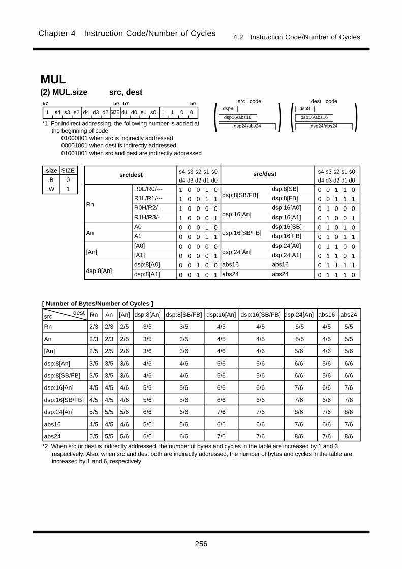
256
Chapter 4 Instruction Code/Number of Cycles 4.2 Instruction Code/Number of Cycles
src dest Rn An [An] dsp:8[An] dsp:8[SB/FB] dsp:16[An] dsp:16[SB/FB] dsp:24[An] abs16 abs24
Rn 2/3 2/3 2/5 3/5 3/5 4/5 4/5 5/5 4/5 5/5
An 2/3 2/3 2/5 3/5 3/5 4/5 4/5 5/5 4/5 5/5
[An] 2/5 2/5 2/6 3/6 3/6 4/6 4/6 5/6 4/6 5/6
dsp:8[An] 3/5 3/5 3/6 4/6 4/6 5/6 5/6 6/6 5/6 6/6
dsp:8[SB/FB] 3/5 3/5 3/6 4/6 4/6 5/6 5/6 6/6 5/6 6/6
dsp:16[An] 4/5 4/5 4/6 5/6 5/6 6/6 6/6 7/6 6/6 7/6
dsp:16[SB/FB] 4/5 4/5 4/6 5/6 5/6 6/6 6/6 7/6 6/6 7/6
dsp:24[An] 5/5 5/5 5/6 6/6 6/6 7/6 7/6 8/6 7/6 8/6
abs16 4/5 4/5 4/6 5/6 5/6 6/6 6/6 7/6 6/6 7/6
abs24 5/5 5/5 5/6 6/6 6/6 7/6 7/6 8/6 7/6 8/6
(2) MUL.size src, dest
.size
.B
.W
SIZE
0
1
b7 b0 b7 b0
1 s4 s3 s2 d4 d3 d2 SIZE d1 d0 s1 s0 1 1 0 0
R0L/R0/---
R1L/R1/---
R0H/R2/-
R1H/R3/-
A0
A1
[A0]
[A1]
dsp:8[A0]
dsp:8[A1]
dsp:8[SB/FB]
dsp:16[An]
dsp:16[SB/FB]
dsp:24[An]
abs16
abs24
Rn
An
[An]
dsp:8[An]
src/destsrc/dest s4 s3 s2 s1 s0d4 d3 d2 d1 d0
1 0 0 1 0
1 0 0 1 1
1 0 0 0 0
1 0 0 0 1
0 0 0 1 0
0 0 0 1 1
0 0 0 0 0
0 0 0 0 1
0 0 1 0 0
0 0 1 0 1
s4 s3 s2 s1 s0d4 d3 d2 d1 d0
0 0 1 1 0
0 0 1 1 1
0 1 0 0 0
0 1 0 0 1
0 1 0 1 0
0 1 0 1 1
0 1 1 0 0
0 1 1 0 1
0 1 1 1 1
0 1 1 1 0
dsp24/abs24
dsp8
dsp16/abs16 )(
dsp:8[SB]
dsp:8[FB]
dsp:16[A0]
dsp:16[A1]
dsp:16[SB]
dsp:16[FB]
dsp:24[A0]
dsp:24[A1]
abs16
abs24
dsp24/abs24
dsp8
dsp16/abs16 )(MUL
dest codesrc code
*1 For indirect addressing, the following number is added atthe beginning of code:
01000001 when src is indirectly addressed00001001 when dest is indirectly addressed01001001 when src and dest are indirectly addressed
*2 When src or dest is indirectly addressed, the number of bytes and cycles in the table are increased by 1 and 3respectively. Also, when src and dest both are indirectly addressed, the number of bytes and cycles in the table areincreased by 1 and 6, respectively.
[ Number of Bytes/Number of Cycles ]

257
Chapter 4 Instruction Code/Number of Cycles 4.2 Instruction Code/Number of Cycles
(1) MULEX srcb7 b0 b7 b0
1 1 0 0 s4 s3 s2 1 s1 s0 1 1 1 1 1 0
---/---/---
---/---/---
---/---/-
---/R3/-
A0
A1
[A0]
[A1]
dsp:8[A0]
dsp:8[A1]
dsp:8[SB/FB]
dsp:16[An]
dsp:16[SB/FB]
dsp:24[An]
abs16
abs24
Rn
An
[An]
dsp:8[An]
srcsrc s4 s3 s2 s1 s0
1 0 0 1 0
1 0 0 1 1
1 0 0 0 0
1 0 0 0 1
0 0 0 1 0
0 0 0 1 1
0 0 0 0 0
0 0 0 0 1
0 0 1 0 0
0 0 1 0 1
s4 s3 s2 s1 s0
0 0 1 1 0
0 0 1 1 1
0 1 0 0 0
0 1 0 0 1
0 1 0 1 0
0 1 0 1 1
0 1 1 0 0
0 1 1 0 1
0 1 1 1 1
0 1 1 1 0
dsp24/abs24
dsp8
dsp16/abs16 )(dsp:8[SB]
dsp:8[FB]
dsp:16[A0]
dsp:16[A1]
dsp:16[SB]
dsp:16[FB]
dsp:24[A0]
dsp:24[A1]
abs16
abs24
MULEX
(1) MULU.size #IMM, dest
.size
.B
.W
SIZE
0
1
b7 b0 b7 b0
1 0 0 0 d4 d3 d2 SIZE d1 d0 0 0 1 1 1 1
R0L/R0/---
R1L/R1/---
R0H/R2/-
R1H/R3/-
A0
A1
[A0]
[A1]
dsp:8[A0]
dsp:8[A1]
dsp:8[SB/FB]
dsp:16[An]
dsp:16[SB/FB]
dsp:24[An]
abs16
abs24
Rn
An
[An]
dsp:8[An]
destdest d4 d3 d2 d1 d0
1 0 0 1 0
1 0 0 1 1
1 0 0 0 0
1 0 0 0 1
0 0 0 1 0
0 0 0 1 1
0 0 0 0 0
0 0 0 0 1
0 0 1 0 0
0 0 1 0 1
d4 d3 d2 d1 d0
0 0 1 1 0
0 0 1 1 1
0 1 0 0 0
0 1 0 0 1
0 1 0 1 0
0 1 0 1 1
0 1 1 0 0
0 1 1 0 1
0 1 1 1 1
0 1 1 1 0
dsp24/abs24
dsp8
dsp16/abs16 )(dsp:8[SB]
dsp:8[FB]
dsp:16[A0]
dsp:16[A1]
dsp:16[SB]
dsp:16[FB]
dsp:24[A0]
dsp:24[A1]
abs16
abs24
MULU
#IMM8
#IMM16
src Rn An [An] dsp:8[An] dsp:8[SB/FB] dsp:16[An] dsp:16[SB/FB] dsp:24[An] abs16 abs24
Bytes/Cycles 2/8 2/8 2/10 3/10 3/10 4/10 4/10 5/10 4/10 5/10
dest Rn An [An] dsp:8[An] dsp:8[SB/FB] dsp:16[An] dsp:16[SB/FB] dsp:24[An] abs16 abs24
Bytes/Cycles 3/3 3/3 3/5 4/5 4/5 5/5 5/5 6/5 5/5 6/5
src code
*1 When src is indirectly addressed the code has 00001001added at the beginning.
[ Number of Bytes/Number of Cycles ]
*2 When src is indirectly addressed, the number of bytes and cycles in the table are increased by 1 and 3 respectively.
dest code
*1 When dest is indirectly addressed the code has 00001001added at the beginning.
[ Number of Bytes/Number of Cycles ]
*2 When dest is indirectly addressed, the number of bytes and cycles in the table are increased by 1 and 3, respectively.*3 When (.W) is specified for the size specifier(.size) the number of bytes in the table is increased by 1.
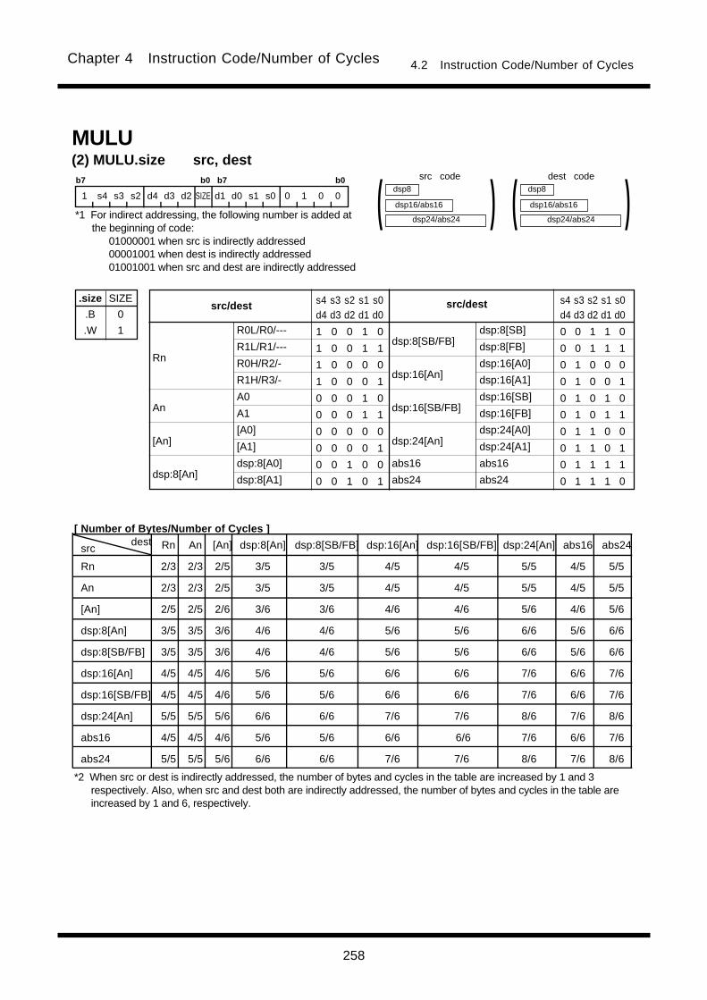
258
Chapter 4 Instruction Code/Number of Cycles 4.2 Instruction Code/Number of Cycles
srcdest Rn An [An] dsp:8[An] dsp:8[SB/FB] dsp:16[An] dsp:16[SB/FB] dsp:24[An] abs16 abs24
Rn 2/3 2/3 2/5 3/5 3/5 4/5 4/5 5/5 4/5 5/5
An 2/3 2/3 2/5 3/5 3/5 4/5 4/5 5/5 4/5 5/5
[An] 2/5 2/5 2/6 3/6 3/6 4/6 4/6 5/6 4/6 5/6
dsp:8[An] 3/5 3/5 3/6 4/6 4/6 5/6 5/6 6/6 5/6 6/6
dsp:8[SB/FB] 3/5 3/5 3/6 4/6 4/6 5/6 5/6 6/6 5/6 6/6
dsp:16[An] 4/5 4/5 4/6 5/6 5/6 6/6 6/6 7/6 6/6 7/6
dsp:16[SB/FB] 4/5 4/5 4/6 5/6 5/6 6/6 6/6 7/6 6/6 7/6
dsp:24[An] 5/5 5/5 5/6 6/6 6/6 7/6 7/6 8/6 7/6 8/6
abs16 4/5 4/5 4/6 5/6 5/6 6/6 6/6 7/6 6/6 7/6
abs24 5/5 5/5 5/6 6/6 6/6 7/6 7/6 8/6 7/6 8/6
(2) MULU.size src, dest
.size
.B
.W
SIZE
0
1
b7 b0 b7 b0
1 s4 s3 s2 d4 d3 d2 SIZE d1 d0 s1 s0 0 1 0 0
R0L/R0/---
R1L/R1/---
R0H/R2/-
R1H/R3/-
A0
A1
[A0]
[A1]
dsp:8[A0]
dsp:8[A1]
dsp:8[SB/FB]
dsp:16[An]
dsp:16[SB/FB]
dsp:24[An]
abs16
abs24
Rn
An
[An]
dsp:8[An]
src/destsrc/dest s4 s3 s2 s1 s0d4 d3 d2 d1 d0
1 0 0 1 0
1 0 0 1 1
1 0 0 0 0
1 0 0 0 1
0 0 0 1 0
0 0 0 1 1
0 0 0 0 0
0 0 0 0 1
0 0 1 0 0
0 0 1 0 1
s4 s3 s2 s1 s0d4 d3 d2 d1 d0
0 0 1 1 0
0 0 1 1 1
0 1 0 0 0
0 1 0 0 1
0 1 0 1 0
0 1 0 1 1
0 1 1 0 0
0 1 1 0 1
0 1 1 1 1
0 1 1 1 0
dsp24/abs24
dsp8
dsp16/abs16 )(
dsp:8[SB]
dsp:8[FB]
dsp:16[A0]
dsp:16[A1]
dsp:16[SB]
dsp:16[FB]
dsp:24[A0]
dsp:24[A1]
abs16
abs24
dsp24/abs24
dsp8
dsp16/abs16 )(MULU
src code dest code
*1 For indirect addressing, the following number is added atthe beginning of code:
01000001 when src is indirectly addressed00001001 when dest is indirectly addressed01001001 when src and dest are indirectly addressed
[ Number of Bytes/Number of Cycles ]
*2 When src or dest is indirectly addressed, the number of bytes and cycles in the table are increased by 1 and 3respectively. Also, when src and dest both are indirectly addressed, the number of bytes and cycles in the table areincreased by 1 and 6, respectively.

259
Chapter 4 Instruction Code/Number of Cycles 4.2 Instruction Code/Number of Cycles
(1) NEG.size dest
.size
.B
.W
SIZE
0
1
b7 b0 b7 b0
1 0 1 0 d4 d3 d2 SIZE d1 d0 1 0 1 1 1 1
R0L/R0/---
R1L/R1/---
R0H/R2/-
R1H/R3/-
A0
A1
[A0]
[A1]
dsp:8[A0]
dsp:8[A1]
dsp:8[SB/FB]
dsp:16[An]
dsp:16[SB/FB]
dsp:24[An]
abs16
abs24
Rn
An
[An]
dsp:8[An]
destdest d4 d3 d2 d1 d0
1 0 0 1 0
1 0 0 1 1
1 0 0 0 0
1 0 0 0 1
0 0 0 1 0
0 0 0 1 1
0 0 0 0 0
0 0 0 0 1
0 0 1 0 0
0 0 1 0 1
d4 d3 d2 d1 d0
0 0 1 1 0
0 0 1 1 1
0 1 0 0 0
0 1 0 0 1
0 1 0 1 0
0 1 0 1 1
0 1 1 0 0
0 1 1 0 1
0 1 1 1 1
0 1 1 1 0
dsp24/abs24
dsp8
dsp16/abs16 )(dsp:8[SB]
dsp:8[FB]
dsp:16[A0]
dsp:16[A1]
dsp:16[SB]
dsp:16[FB]
dsp:24[A0]
dsp:24[A1]
abs16
abs24
NEG
(1) NOPNOP
Bytes/Cycles 1/1
b7 b0
1 1 0 1 1 1 1 0
dest Rn An [An] dsp:8[An] dsp:8[SB/FB] dsp:16[An] dsp:16[SB/FB] dsp:24[An] abs16 abs24
Bytes/Cycles 2/1 2/1 2/3 3/3 3/3 4/3 4/3 5/3 4/3 5/3
dest code
*1 When dest is indirectly addressed the code has 00001001added at the beginning.
[ Number of Bytes/Number of Cycles ]
*2 When dest is indirectly addressed, the number of bytes and cycles in the table are increased by 1 and 3 respectively.
[ Number of Bytes/Number of Cycles ]
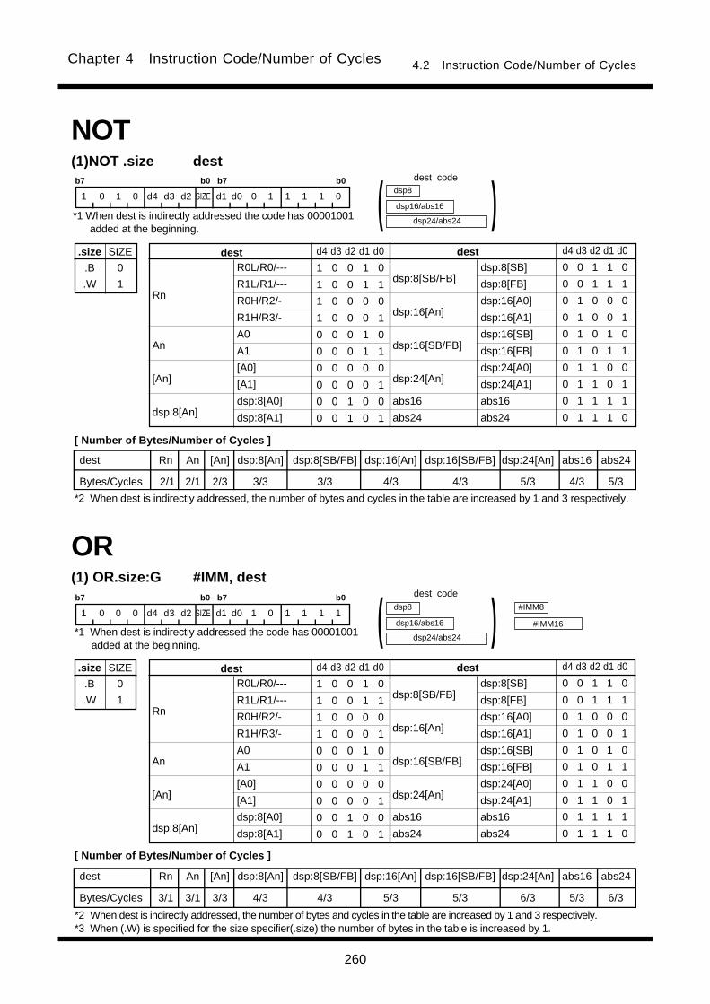
260
Chapter 4 Instruction Code/Number of Cycles 4.2 Instruction Code/Number of Cycles
b7 b0 b7 b0
1 0 1 0 d4 d3 d2 SIZE d1 d0 0 1 1 1 1 0
R0L/R0/---
R1L/R1/---
R0H/R2/-
R1H/R3/-
A0
A1
[A0]
[A1]
dsp:8[A0]
dsp:8[A1]
dsp:8[SB/FB]
dsp:16[An]
dsp:16[SB/FB]
dsp:24[An]
abs16
abs24
Rn
An
[An]
dsp:8[An]
destdest d4 d3 d2 d1 d0
1 0 0 1 0
1 0 0 1 1
1 0 0 0 0
1 0 0 0 1
0 0 0 1 0
0 0 0 1 1
0 0 0 0 0
0 0 0 0 1
0 0 1 0 0
0 0 1 0 1
d4 d3 d2 d1 d0
0 0 1 1 0
0 0 1 1 1
0 1 0 0 0
0 1 0 0 1
0 1 0 1 0
0 1 0 1 1
0 1 1 0 0
0 1 1 0 1
0 1 1 1 1
0 1 1 1 0
dsp:8[SB]
dsp:8[FB]
dsp:16[A0]
dsp:16[A1]
dsp:16[SB]
dsp:16[FB]
dsp:24[A0]
dsp:24[A1]
abs16
abs24
.size
.B
.W
SIZE
0
1
(1)NOT .size dest
dsp24/abs24
dsp8
dsp16/abs16 )(NOT
(1) OR.size:G #IMM, dest
#IMM8
#IMM16
OR
b7 b0 b7 b0
1 0 0 0 d4 d3 d2 SIZE d1 d0 1 0 1 1 1 1
R0L/R0/---
R1L/R1/---
R0H/R2/-
R1H/R3/-
A0
A1
[A0]
[A1]
dsp:8[A0]
dsp:8[A1]
dsp:8[SB/FB]
dsp:16[An]
dsp:16[SB/FB]
dsp:24[An]
abs16
abs24
Rn
An
[An]
dsp:8[An]
destdest d4 d3 d2 d1 d0
1 0 0 1 0
1 0 0 1 1
1 0 0 0 0
1 0 0 0 1
0 0 0 1 0
0 0 0 1 1
0 0 0 0 0
0 0 0 0 1
0 0 1 0 0
0 0 1 0 1
d4 d3 d2 d1 d0
0 0 1 1 0
0 0 1 1 1
0 1 0 0 0
0 1 0 0 1
0 1 0 1 0
0 1 0 1 1
0 1 1 0 0
0 1 1 0 1
0 1 1 1 1
0 1 1 1 0
dsp:8[SB]
dsp:8[FB]
dsp:16[A0]
dsp:16[A1]
dsp:16[SB]
dsp:16[FB]
dsp:24[A0]
dsp:24[A1]
abs16
abs24
.size
.B
.W
SIZE
0
1
dsp24/abs24
dsp8
dsp16/abs16 )(
dest Rn An [An] dsp:8[An] dsp:8[SB/FB] dsp:16[An] dsp:16[SB/FB] dsp:24[An] abs16 abs24
Bytes/Cycles 2/1 2/1 2/3 3/3 3/3 4/3 4/3 5/3 4/3 5/3
dest Rn An [An] dsp:8[An] dsp:8[SB/FB] dsp:16[An] dsp:16[SB/FB] dsp:24[An] abs16 abs24
Bytes/Cycles 3/1 3/1 3/3 4/3 4/3 5/3 5/3 6/3 5/3 6/3
dest code
*1 When dest is indirectly addressed the code has 00001001added at the beginning.
[ Number of Bytes/Number of Cycles ]
*2 When dest is indirectly addressed, the number of bytes and cycles in the table are increased by 1 and 3 respectively.
*1 When dest is indirectly addressed the code has 00001001added at the beginning.
dest code
[ Number of Bytes/Number of Cycles ]
*2 When dest is indirectly addressed, the number of bytes and cycles in the table are increased by 1 and 3 respectively.*3 When (.W) is specified for the size specifier(.size) the number of bytes in the table is increased by 1.
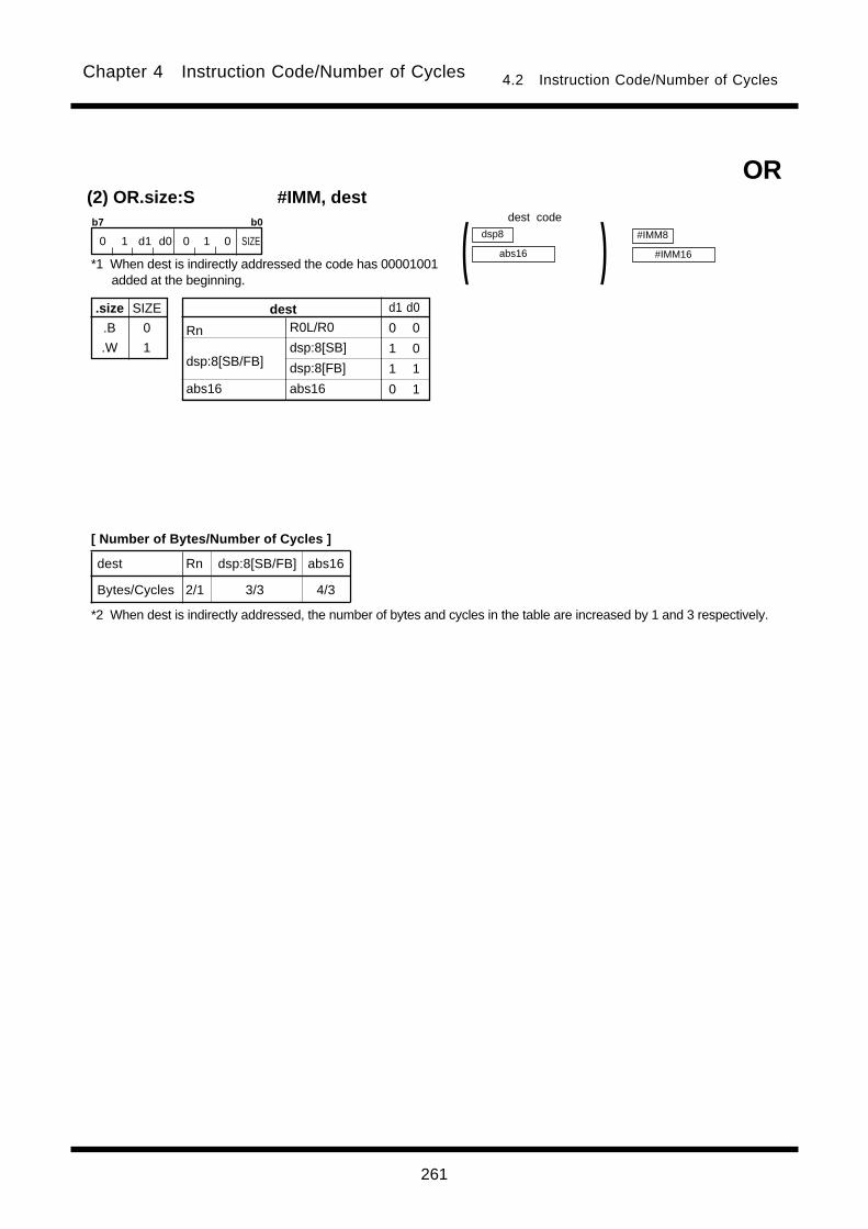
261
Chapter 4 Instruction Code/Number of Cycles 4.2 Instruction Code/Number of Cycles
(2) OR.size:S #IMM, destb7 b0
0 1 d1 d0 0 1 0 SIZEdsp8
abs16 )(OR
dest Rn dsp:8[SB/FB] abs16
Bytes/Cycles 2/1 3/3 4/3
.size
.B
.W
SIZE
0
1
R0L/R0
dsp:8[SB]
dsp:8[FB]
abs16
Rn
dsp:8[SB/FB]
abs16
dest d1 d0
0 0
1 0
1 1
0 1
#IMM8
#IMM16
dest code
*1 When dest is indirectly addressed the code has 00001001added at the beginning.
[ Number of Bytes/Number of Cycles ]
*2 When dest is indirectly addressed, the number of bytes and cycles in the table are increased by 1 and 3 respectively.
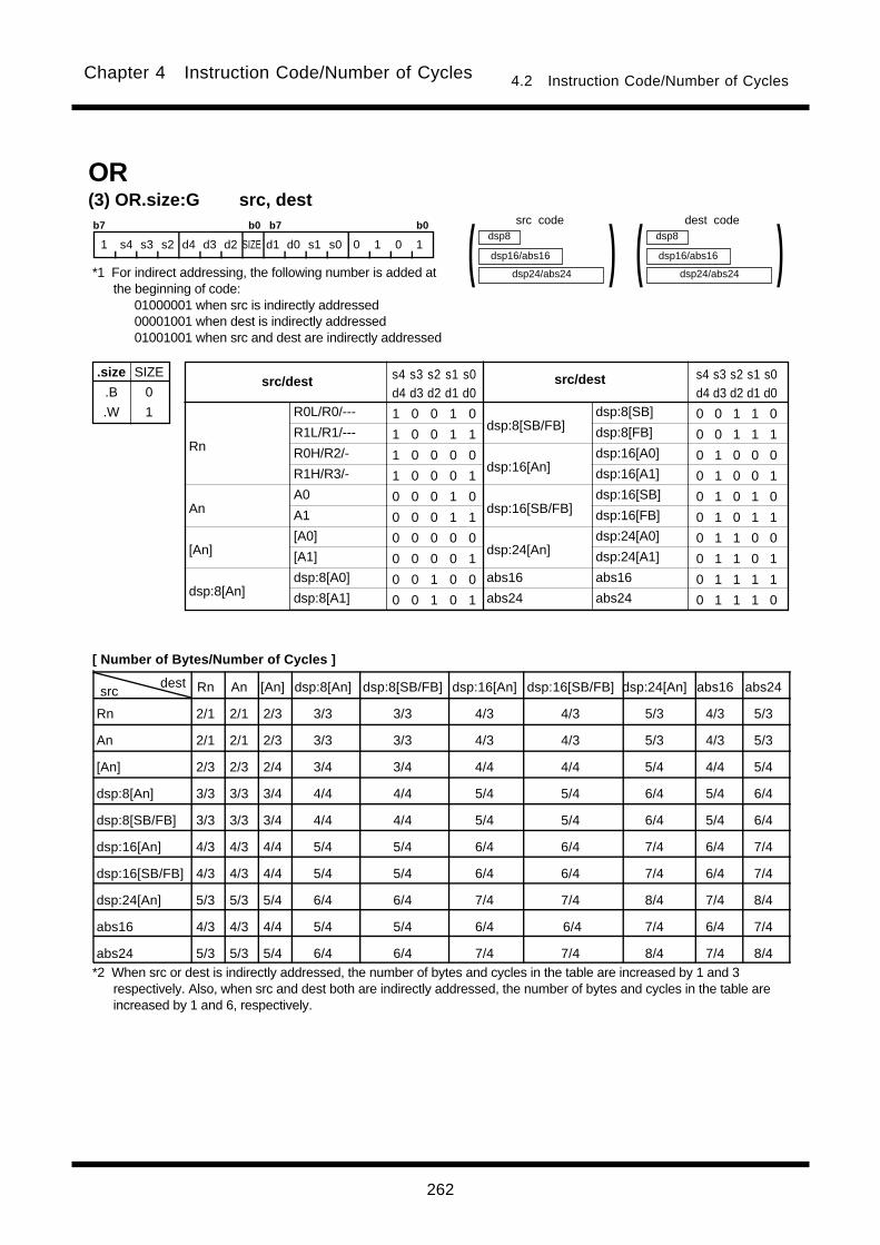
262
Chapter 4 Instruction Code/Number of Cycles 4.2 Instruction Code/Number of Cycles
src dest Rn An [An] dsp:8[An] dsp:8[SB/FB] dsp:16[An] dsp:16[SB/FB] dsp:24[An] abs16 abs24
Rn 2/1 2/1 2/3 3/3 3/3 4/3 4/3 5/3 4/3 5/3
An 2/1 2/1 2/3 3/3 3/3 4/3 4/3 5/3 4/3 5/3
[An] 2/3 2/3 2/4 3/4 3/4 4/4 4/4 5/4 4/4 5/4
dsp:8[An] 3/3 3/3 3/4 4/4 4/4 5/4 5/4 6/4 5/4 6/4
dsp:8[SB/FB] 3/3 3/3 3/4 4/4 4/4 5/4 5/4 6/4 5/4 6/4
dsp:16[An] 4/3 4/3 4/4 5/4 5/4 6/4 6/4 7/4 6/4 7/4
dsp:16[SB/FB] 4/3 4/3 4/4 5/4 5/4 6/4 6/4 7/4 6/4 7/4
dsp:24[An] 5/3 5/3 5/4 6/4 6/4 7/4 7/4 8/4 7/4 8/4
abs16 4/3 4/3 4/4 5/4 5/4 6/4 6/4 7/4 6/4 7/4
abs24 5/3 5/3 5/4 6/4 6/4 7/4 7/4 8/4 7/4 8/4
(3) OR.size:G src, dest
.size
.B
.W
SIZE
0
1
b7 b0 b7 b0
1 s4 s3 s2 d4 d3 d2 SIZE d1 d0 s1 s0 0 1 0 1
R0L/R0/---
R1L/R1/---
R0H/R2/-
R1H/R3/-
A0
A1
[A0]
[A1]
dsp:8[A0]
dsp:8[A1]
dsp:8[SB/FB]
dsp:16[An]
dsp:16[SB/FB]
dsp:24[An]
abs16
abs24
Rn
An
[An]
dsp:8[An]
src/destsrc/dest s4 s3 s2 s1 s0d4 d3 d2 d1 d0
1 0 0 1 0
1 0 0 1 1
1 0 0 0 0
1 0 0 0 1
0 0 0 1 0
0 0 0 1 1
0 0 0 0 0
0 0 0 0 1
0 0 1 0 0
0 0 1 0 1
s4 s3 s2 s1 s0d4 d3 d2 d1 d0
0 0 1 1 0
0 0 1 1 1
0 1 0 0 0
0 1 0 0 1
0 1 0 1 0
0 1 0 1 1
0 1 1 0 0
0 1 1 0 1
0 1 1 1 1
0 1 1 1 0
dsp24/abs24
dsp8
dsp16/abs16 )(
dsp:8[SB]
dsp:8[FB]
dsp:16[A0]
dsp:16[A1]
dsp:16[SB]
dsp:16[FB]
dsp:24[A0]
dsp:24[A1]
abs16
abs24
dsp24/abs24
dsp8
dsp16/abs16 )(OR
dest codesrc code
*1 For indirect addressing, the following number is added atthe beginning of code:
01000001 when src is indirectly addressed00001001 when dest is indirectly addressed01001001 when src and dest are indirectly addressed
[ Number of Bytes/Number of Cycles ]
*2 When src or dest is indirectly addressed, the number of bytes and cycles in the table are increased by 1 and 3respectively. Also, when src and dest both are indirectly addressed, the number of bytes and cycles in the table areincreased by 1 and 6, respectively.

263
Chapter 4 Instruction Code/Number of Cycles 4.2 Instruction Code/Number of Cycles
POPC(1) POPC destb7 b0 b7 b0
1 1 0 1 0 0 1 1 1 0 1 0 1 DEST
DCT0
DCT1
FLG
SVF
destdest DEST
0 0 0
0 0 1
0 1 0
0 1 1
DEST
1 0 0
1 0 1
1 1 0
1 1 1
DRC0
DRC1
DMD0
DMD1
Bytes/Cycles 2/3
POP(1) POP.size dest
.size
.B
.W
SIZE
0
1
b7 b0 b7 b0
1 0 1 1 d4 d3 d2 SIZE d1 d0 1 0 1 1 1 1
R0L/R0/---
R1L/R1/---
R0H/R2/-
R1H/R3/-
A0
A1
[A0]
[A1]
dsp:8[A0]
dsp:8[A1]
dsp:8[SB/FB]
dsp:16[An]
dsp:16[SB/FB]
dsp:24[An]
abs16
abs24
Rn
An
[An]
dsp:8[An]
destdest d4 d3 d2 d1 d0
1 0 0 1 0
1 0 0 1 1
1 0 0 0 0
1 0 0 0 1
0 0 0 1 0
0 0 0 1 1
0 0 0 0 0
0 0 0 0 1
0 0 1 0 0
0 0 1 0 1
d4 d3 d2 d1 d0
0 0 1 1 0
0 0 1 1 1
0 1 0 0 0
0 1 0 0 1
0 1 0 1 0
0 1 0 1 1
0 1 1 0 0
0 1 1 0 1
0 1 1 1 1
0 1 1 1 0
dsp24/abs24
dsp8
dsp16/abs16 )(dsp:8[SB]
dsp:8[FB]
dsp:16[A0]
dsp:16[A1]
dsp:16[SB]
dsp:16[FB]
dsp:24[A0]
dsp:24[A1]
abs16
abs24
dest Rn An [An] dsp:8[An] dsp:8[SB/FB] dsp:16[An] dsp:16[SB/FB] dsp:24[An] abs16 abs24
Bytes/Cycles 2/3 2/3 2/3 3/3 3/3 4/3 4/3 5/3 4/3 5/3
dest code
*1 When dest is indirectly addressed the code has 00001001added at the beginning.
[ Number of Bytes/Number of Cycles ]
*2 When dest is indirectly addressed, the number of bytes and cycles in the table are increased by 1 and 3 respectively.
[ Number of Bytes/Number of Cycles ]
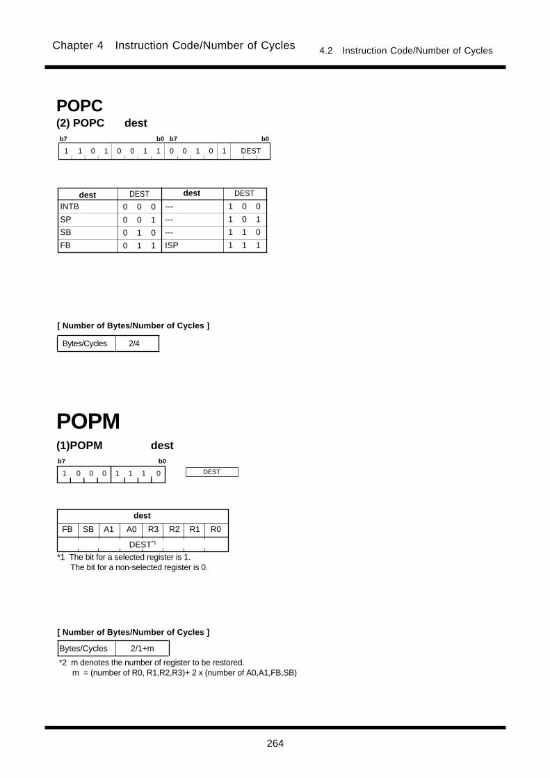
264
Chapter 4 Instruction Code/Number of Cycles 4.2 Instruction Code/Number of Cycles
POPC(2) POPC destb7 b0 b7 b0
1 1 0 1 0 0 1 1 0 0 1 0 1 DEST
INTB
SP
SB
FB
destdest DEST
0 0 0
0 0 1
0 1 0
0 1 1
DEST
1 0 0
1 0 1
1 1 0
1 1 1
---
---
---
ISP
Bytes/Cycles 2/4
(1)POPM destb7 b0
1 0 0 0 1 1 1 0
POPM
Bytes/Cycles 2/1+m
*2 m denotes the number of register to be restored. m = (number of R0, R1,R2,R3)+ 2 x (number of A0,A1,FB,SB)
dest
FB SB R3 R2 R1 R0A1 A0
DEST*1
*1 The bit for a selected register is 1. The bit for a non-selected register is 0.
DEST
[ Number of Bytes/Number of Cycles ]
[ Number of Bytes/Number of Cycles ]

265
Chapter 4 Instruction Code/Number of Cycles 4.2 Instruction Code/Number of Cycles
PUSH
(1) PUSH.size #IMMb7 b0
1 0 1 0 1 1 1 SIZE#IMM8
#IMM16
Bytes/Cycles 2/1
.size
.B
.W
SIZE
0
1
b7 b0 b7 b0
1 1 0 0 s4 s3 s2 SIZE s1 s0 0 0 1 1 1 0
dsp24/abs24
dsp8
dsp16/abs16 )(
src Rn An [An] dsp:8[An] dsp:8[SB/FB] dsp:16[An] dsp:16[SB/FB] dsp:24[An] abs16 abs24
Bytes/Cycles 2/1 2/1 2/3 3/3 3/3 4/3 4/3 5/3 4/3 5/3
R0L/R0/---
R1L/R1/---
R0H/R2/-
R1H/R3/-
A0
A1
[A0]
[A1]
dsp:8[A0]
dsp:8[A1]
dsp:8[SB/FB]
dsp:16[An]
dsp:16[SB/FB]
dsp:24[An]
abs16
abs24
Rn
An
[An]
dsp:8[An]
srcsrc s4 s3 s2 s1 s0
1 0 0 1 0
1 0 0 1 1
1 0 0 0 0
1 0 0 0 1
0 0 0 1 0
0 0 0 1 1
0 0 0 0 0
0 0 0 0 1
0 0 1 0 0
0 0 1 0 1
s4 s3 s2 s1 s0
0 0 1 1 0
0 0 1 1 1
0 1 0 0 0
0 1 0 0 1
0 1 0 1 0
0 1 0 1 1
0 1 1 0 0
0 1 1 0 1
0 1 1 1 1
0 1 1 1 0
dsp:8[SB]
dsp:8[FB]
dsp:16[A0]
dsp:16[A1]
dsp:16[SB]
dsp:16[FB]
dsp:24[A0]
dsp:24[A1]
abs16
abs24
PUSH
.size
.B
.W
SIZE
0
1
(2) PUSH.size src
[ Number of Bytes/Number of Cycles ]
*1 When (.W) is specified for the size specifier(.size) the number of bytes in the table is increased by 1.
*1 When src is indirectly addressed the code has 00001001added at the beginning.
src code
[ Number of Bytes/Number of Cycles ]
*2 When src is indirectly addressed, the number of bytes and cycles in the table are increased by 1 and 3 respectively.

266
Chapter 4 Instruction Code/Number of Cycles 4.2 Instruction Code/Number of Cycles
b7 b0 b7 b0
1 0 1 0 s4 s3 s2 0 s1 s0 0 0 0 0 0 1
dsp24/abs24
dsp8
dsp16/abs16 )(
src Rn An [An] dsp:8[An] dsp:8[SB/FB] dsp:16[An] dsp:16[SB/FB] dsp:24[An] abs16 abs24
Bytes/Cycles 2/2 2/2 2/5 3/5 3/5 4/5 4/5 5/5 4/5 5/5
---/---/R2R0
---/---/R3R1
---/---/-
---/---/-
A0
A1
[A0]
[A1]
dsp:8[A0]
dsp:8[A1]
dsp:8[SB/FB]
dsp:16[An]
dsp:16[SB/FB]
dsp:24[An]
abs16
abs24
Rn
An
[An]
dsp:8[An]
srcsrc s4 s3 s2 s1 s0
1 0 0 1 0
1 0 0 1 1
1 0 0 0 0
1 0 0 0 1
0 0 0 1 0
0 0 0 1 1
0 0 0 0 0
0 0 0 0 1
0 0 1 0 0
0 0 1 0 1
s4 s3 s2 s1 s0
0 0 1 1 0
0 0 1 1 1
0 1 0 0 0
0 1 0 0 1
0 1 0 1 0
0 1 0 1 1
0 1 1 0 0
0 1 1 0 1
0 1 1 1 1
0 1 1 1 0
dsp:8[SB]
dsp:8[FB]
dsp:16[A0]
dsp:16[A1]
dsp:16[SB]
dsp:16[FB]
dsp:24[A0]
dsp:24[A1]
abs16
abs24
PUSH(4) PUSH.L src
PUSH(3) PUSH.L #IMM32b7 b0 b7 b0
1 0 1 1 0 1 1 0 0 1 0 1 0 0 1 1 #IMM32
Bytes/Cycles 6/3
[ Number of Bytes/Number of Cycles ]
src code
*1 When src is indirectly addressed the code has 00001001added at the beginning.
[ Number of Bytes/Number of Cycles ]
*2 When src is indirectly addressed, the number of bytes and cycles in the table are increased by 1 and 3 respectively.

267
Chapter 4 Instruction Code/Number of Cycles 4.2 Instruction Code/Number of Cycles
PUSHC(1) PUSHC srcb7 b0 b7 b0
1 1 0 1 0 0 0 1 1 0 1 0 1 SRC
DCT0
DCT1
FLG
SVF
srcsrc SRC
0 0 0
0 0 1
0 1 0
0 1 1
SRC
1 0 0
1 0 1
1 1 0
1 1 1
DRC0
DRC1
DMD0
DMD1
Bytes/Cycles 2/1
PUSHA(1) PUSHA srcb7 b0 b7 b0
1 0 1 1 s4 s3 s2 0 s1 s0 0 0 0 0 0 1
---/---/---
---/---/---
---/---/-
---/---/-
---
---
---
---
dsp:8[A0]
dsp:8[A1]
dsp:8[SB/FB]
dsp:16[An]
dsp:16[SB/FB]
dsp:24[An]
abs16
abs24
Rn
An
[An]
dsp:8[An]
srcsrc s4 s3 s2 s1 s0
1 0 0 1 0
1 0 0 1 1
1 0 0 0 0
1 0 0 0 1
0 0 0 1 0
0 0 0 1 1
0 0 0 0 0
0 0 0 0 1
0 0 1 0 0
0 0 1 0 1
s4 s3 s2 s1s0
0 0 1 1 0
0 0 1 1 1
0 1 0 0 0
0 1 0 0 1
0 1 0 1 0
0 1 0 1 1
0 1 1 0 0
0 1 1 0 1
0 1 1 1 1
0 1 1 1 0
dsp24/abs24
dsp8
dsp16/abs16 )(dsp:8[SB]
dsp:8[FB]
dsp:16[A0]
dsp:16[A1]
dsp:16[SB]
dsp:16[FB]
dsp:24[A0]
dsp:24[A1]
abs16
abs24
src code
[ Number of Bytes/Number of Cycles ]
[ Number of Bytes/Number of Cycles ]
src dsp:8[An] dsp:8[SB/FB] dsp:16[An] dsp:16[SB/FB] dsp:24[An] abs16 abs24
Bytes/Cycles 3/3 3/3 4/3 4/3 5/3 4/3 5/3
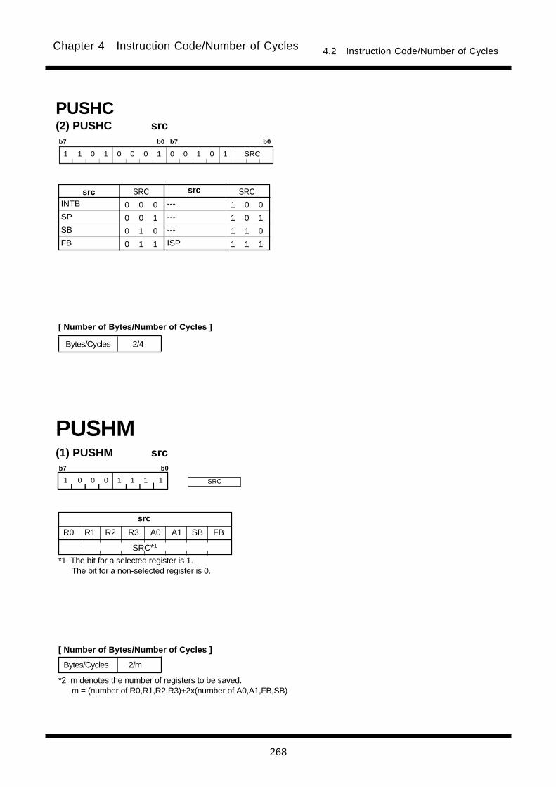
268
Chapter 4 Instruction Code/Number of Cycles 4.2 Instruction Code/Number of Cycles
PUSHC(2) PUSHC srcb7 b0 b7 b0
1 1 0 1 0 0 0 1 0 0 1 0 1 SRC
INTB
SP
SB
FB
srcsrc SRC
0 0 0
0 0 1
0 1 0
0 1 1
SRC
1 0 0
1 0 1
1 1 0
1 1 1
---
---
---
ISP
Bytes/Cycles 2/4
(1) PUSHM src
PUSHM
b7 b0
1 0 0 0 1 1 1 1
Bytes/Cycles 2/m
src
R0 R1 A0 A1 SB FBR2 R3
SRC*1
*1 The bit for a selected register is 1. The bit for a non-selected register is 0.
*2 m denotes the number of registers to be saved. m = (number of R0,R1,R2,R3)+2x(number of A0,A1,FB,SB)
SRC
[ Number of Bytes/Number of Cycles ]
[ Number of Bytes/Number of Cycles ]
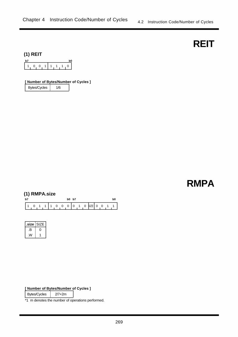
269
Chapter 4 Instruction Code/Number of Cycles 4.2 Instruction Code/Number of Cycles
RMPA(1) RMPA.size
.size
.B
.W
SIZE
0
1
b7 b0 b7 b0
1 0 1 1 1 0 0 0 0 1 0 SIZE 0 0 1 1
Bytes/Cycles 2/7+2m
*1 m denotes the number of operations performed.
(1) REIT
REIT
b7 b0
1 0 0 1 1 1 1 0
Bytes/Cycles 1/6
[ Number of Bytes/Number of Cycles ]
[ Number of Bytes/Number of Cycles ]

270
Chapter 4 Instruction Code/Number of Cycles 4.2 Instruction Code/Number of Cycles
ROLC(1) ROLC.size dest
.size
.B
.W
SIZE
0
1
b7 b0 b7 b0
1 0 1 1 d4 d3 d2 SIZE d1 d0 1 0 1 1 1 0
R0L/R0/---
R1L/R1/---
R0H/R2/-
R1H/R3/-
A0
A1
[A0]
[A1]
dsp:8[A0]
dsp:8[A1]
dsp:8[SB/FB]
dsp:16[An]
dsp:16[SB/FB]
dsp:24[An]
abs16
abs24
Rn
An
[An]
dsp:8[An]
destdest d4 d3 d2 d1 d0
1 0 0 1 0
1 0 0 1 1
1 0 0 0 0
1 0 0 0 1
0 0 0 1 0
0 0 0 1 1
0 0 0 0 0
0 0 0 0 1
0 0 1 0 0
0 0 1 0 1
d4 d3 d2 d1 d0
0 0 1 1 0
0 0 1 1 1
0 1 0 0 0
0 1 0 0 1
0 1 0 1 0
0 1 0 1 1
0 1 1 0 0
0 1 1 0 1
0 1 1 1 1
0 1 1 1 0
dsp24/abs24
dsp8
dsp16/abs16 )(dsp:8[SB]
dsp:8[FB]
dsp:16[A0]
dsp:16[A1]
dsp:16[SB]
dsp:16[FB]
dsp:24[A0]
dsp:24[A1]
abs16
abs24
dest Rn An [An] dsp:8[An] dsp:8[SB/FB] dsp:16[An] dsp:16[SB/FB] dsp:24[An] abs16 abs24
Bytes/Cycles 2/1 2/1 2/3 3/3 3/3 4/3 4/3 5/3 4/3 5/3
dest Rn An [An] dsp:8[An] dsp:8[SB/FB] dsp:16[An] dsp:16[SB/FB] dsp:24[An] abs16 abs24
Bytes/Cycles 2/1 2/1 2/3 3/3 3/3 4/3 4/3 5/3 4/3 5/3
RORC(1) RORC.size dest
.size
.B
.W
SIZE
0
1
b7 b0 b7 b0
1 0 1 0 d4 d3 d2 SIZE d1 d0 1 0 1 1 1 0
R0L/R0/---
R1L/R1/---
R0H/R2/-
R1H/R3/-
A0
A1
[A0]
[A1]
dsp:8[A0]
dsp:8[A1]
dsp:8[SB/FB]
dsp:16[An]
dsp:16[SB/FB]
dsp:24[An]
abs16
abs24
Rn
An
[An]
dsp:8[An]
destdest d4 d3 d2 d1 d0
1 0 0 1 0
1 0 0 1 1
1 0 0 0 0
1 0 0 0 1
0 0 0 1 0
0 0 0 1 1
0 0 0 0 0
0 0 0 0 1
0 0 1 0 0
0 0 1 0 1
d4 d3 d2 d1 d0
0 0 1 1 0
0 0 1 1 1
0 1 0 0 0
0 1 0 0 1
0 1 0 1 0
0 1 0 1 1
0 1 1 0 0
0 1 1 0 1
0 1 1 1 1
0 1 1 1 0
dsp24/abs24
dsp8
dsp16/abs16 )(dsp:8[SB]
dsp:8[FB]
dsp:16[A0]
dsp:16[A1]
dsp:16[SB]
dsp:16[FB]
dsp:24[A0]
dsp:24[A1]
abs16
abs24
[ Number of Bytes/Number of Cycles ]
*2 When dest is indirectly addressed, the number of bytes and cycles in the table are increased by 1 and 3 respectively.
dest code
*1 When dest is indirectly addressed the code has 00001001added at the beginning.
dest code
*1 When dest is indirectly addressed the code has 00001001added at the beginning.
[ Number of Bytes/Number of Cycles ]
*2 When dest is indirectly addressed, the number of bytes and cycles in the table are increased by 1 and 3 respectively.
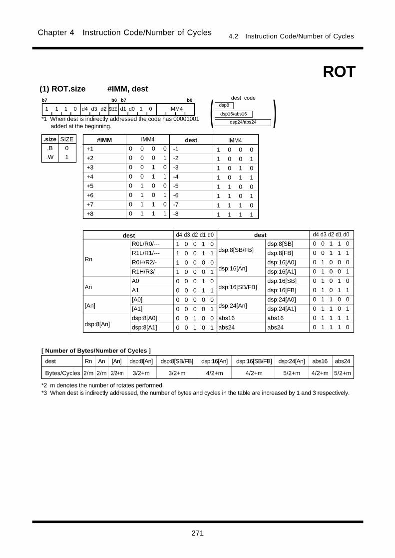
271
Chapter 4 Instruction Code/Number of Cycles 4.2 Instruction Code/Number of Cycles
ROT(1) ROT.size #IMM, dest
.size
.B
.W
SIZE
0
1
b7 b0 b7 b0
1 1 1 0 d4 d3 d2 SIZE d1 d0 1 0 IMM4
+1
+2
+3
+4
+5
+6
+7
+8
dest#IMM IMM4
0 0 0 0
0 0 0 1
0 0 1 0
0 0 1 1
0 1 0 0
0 1 0 1
0 1 1 0
0 1 1 1
IMM4
1 0 0 0
1 0 0 1
1 0 1 0
1 0 1 1
1 1 0 0
1 1 0 1
1 1 1 0
1 1 1 1
dsp24/abs24
dsp8
dsp16/abs16 )(-1
-2
-3
-4
-5
-6
-7
-8
R0L/R0/---
R1L/R1/---
R0H/R2/-
R1H/R3/-
A0
A1
[A0]
[A1]
dsp:8[A0]
dsp:8[A1]
dsp:8[SB/FB]
dsp:16[An]
dsp:16[SB/FB]
dsp:24[An]
abs16
abs24
Rn
An
[An]
dsp:8[An]
destdest d4 d3 d2 d1 d0
1 0 0 1 0
1 0 0 1 1
1 0 0 0 0
1 0 0 0 1
0 0 0 1 0
0 0 0 1 1
0 0 0 0 0
0 0 0 0 1
0 0 1 0 0
0 0 1 0 1
d4 d3 d2 d1 d0
0 0 1 1 0
0 0 1 1 1
0 1 0 0 0
0 1 0 0 1
0 1 0 1 0
0 1 0 1 1
0 1 1 0 0
0 1 1 0 1
0 1 1 1 1
0 1 1 1 0
dsp:8[SB]
dsp:8[FB]
dsp:16[A0]
dsp:16[A1]
dsp:16[SB]
dsp:16[FB]
dsp:24[A0]
dsp:24[A1]
abs16
abs24
*2 m denotes the number of rotates performed.
dest code
*1 When dest is indirectly addressed the code has 00001001added at the beginning.
[ Number of Bytes/Number of Cycles ]
*3 When dest is indirectly addressed, the number of bytes and cycles in the table are increased by 1 and 3 respectively.
dest Rn An [An] dsp:8[An] dsp:8[SB/FB] dsp:16[An] dsp:16[SB/FB] dsp:24[An] abs16 abs24
Bytes/Cycles 2/m 2/m 2/2+m 3/2+m 3/2+m 4/2+m 4/2+m 5/2+m 4/2+m 5/2+m
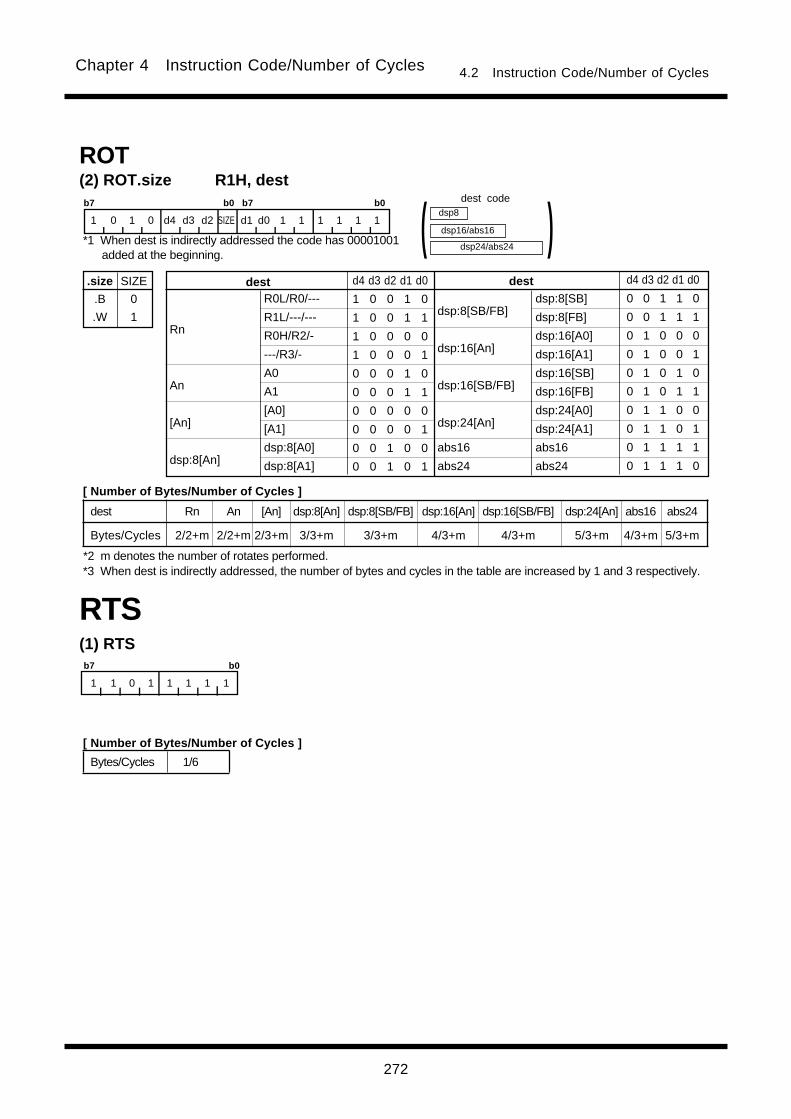
272
Chapter 4 Instruction Code/Number of Cycles 4.2 Instruction Code/Number of Cycles
dest Rn An [An] dsp:8[An] dsp:8[SB/FB] dsp:16[An] dsp:16[SB/FB] dsp:24[An] abs16 abs24
Bytes/Cycles 2/2+m 2/2+m 2/3+m 3/3+m 3/3+m 4/3+m 4/3+m 5/3+m 4/3+m 5/3+m
ROT(2) ROT.size R1H, dest
.size
.B
.W
SIZE
0
1
b7 b0 b7 b0
1 0 1 0 d4 d3 d2 SIZE d1 d0 1 1 1 1 1 1
dsp24/abs24
dsp8
dsp16/abs16 )(R0L/R0/---
R1L/---/---
R0H/R2/-
---/R3/-
A0
A1
[A0]
[A1]
dsp:8[A0]
dsp:8[A1]
dsp:8[SB/FB]
dsp:16[An]
dsp:16[SB/FB]
dsp:24[An]
abs16
abs24
Rn
An
[An]
dsp:8[An]
destdest d4 d3 d2 d1 d0
1 0 0 1 0
1 0 0 1 1
1 0 0 0 0
1 0 0 0 1
0 0 0 1 0
0 0 0 1 1
0 0 0 0 0
0 0 0 0 1
0 0 1 0 0
0 0 1 0 1
d4 d3 d2 d1 d0
0 0 1 1 0
0 0 1 1 1
0 1 0 0 0
0 1 0 0 1
0 1 0 1 0
0 1 0 1 1
0 1 1 0 0
0 1 1 0 1
0 1 1 1 1
0 1 1 1 0
dsp:8[SB]
dsp:8[FB]
dsp:16[A0]
dsp:16[A1]
dsp:16[SB]
dsp:16[FB]
dsp:24[A0]
dsp:24[A1]
abs16
abs24
RTS(1) RTSb7 b0
1 1 0 1 1 1 1 1
Bytes/Cycles 1/6
dest code
*1 When dest is indirectly addressed the code has 00001001added at the beginning.
[ Number of Bytes/Number of Cycles ]
[ Number of Bytes/Number of Cycles ]
*2 m denotes the number of rotates performed.*3 When dest is indirectly addressed, the number of bytes and cycles in the table are increased by 1 and 3 respectively.

273
Chapter 4 Instruction Code/Number of Cycles 4.2 Instruction Code/Number of Cycles
(1) SBB.size #IMM, dest
.size
.B
.W
SIZE
0
1
R0L/R0/---
R1L/R1/---
R0H/R2/-
R1H/R3/-
A0
A1
[A0]
[A1]
dsp:8[A0]
dsp:8[A1]
dsp:8[SB/FB]
dsp:16[An]
dsp:16[SB/FB]
dsp:24[An]
abs16
abs24
Rn
An
[An]
dsp:8[An]
destdest d4 d3 d2 d1 d0
1 0 0 1 0
1 0 0 1 1
1 0 0 0 0
1 0 0 0 1
0 0 0 1 0
0 0 0 1 1
0 0 0 0 0
0 0 0 0 1
0 0 1 0 0
0 0 1 0 1
d4 d3 d2 d1 d0
0 0 1 1 0
0 0 1 1 1
0 1 0 0 0
0 1 0 0 1
0 1 0 1 0
0 1 0 1 1
0 1 1 0 0
0 1 1 0 1
0 1 1 1 1
0 1 1 1 0
dsp:8[SB]
dsp:8[FB]
dsp:16[A0]
dsp:16[A1]
dsp:16[SB]
dsp:16[FB]
dsp:24[A0]
dsp:24[A1]
abs16
abs24
SBB
b7 b0 b7 b0 b7 b0
0000 0001 1 0 0 1 d4 d3 d2 SIZE d1 d0 1 0 1 1 1 0
dsp24/abs24
dsp8
dsp16/abs16 )( #IMM8
#IMM16
dest Rn An [An] dsp:8[An] dsp:8[SB/FB] dsp:16[An] dsp:16[SB/FB] dsp:24[An] abs16 abs24
Bytes/Cycles 4/1 4/1 4/3 5/3 5/3 6/3 6/3 7/3 6/3 7/3
dest code
[ Number of Bytes/Number of Cycles ]
*1 When (.W) is specified for the size specifier(.size),the number of bytes in the table is increased by 1.
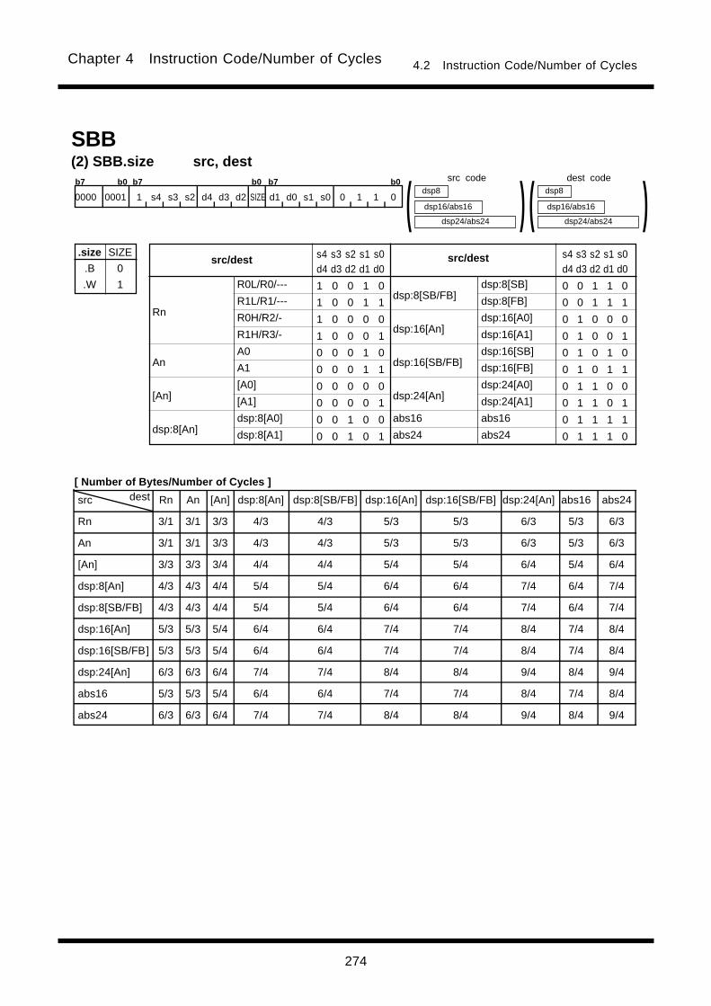
274
Chapter 4 Instruction Code/Number of Cycles 4.2 Instruction Code/Number of Cycles
src dest Rn An [An] dsp:8[An] dsp:8[SB/FB] dsp:16[An] dsp:16[SB/FB] dsp:24[An] abs16 abs24
Rn 3/1 3/1 3/3 4/3 4/3 5/3 5/3 6/3 5/3 6/3
An 3/1 3/1 3/3 4/3 4/3 5/3 5/3 6/3 5/3 6/3
[An] 3/3 3/3 3/4 4/4 4/4 5/4 5/4 6/4 5/4 6/4
dsp:8[An] 4/3 4/3 4/4 5/4 5/4 6/4 6/4 7/4 6/4 7/4
dsp:8[SB/FB] 4/3 4/3 4/4 5/4 5/4 6/4 6/4 7/4 6/4 7/4
dsp:16[An] 5/3 5/3 5/4 6/4 6/4 7/4 7/4 8/4 7/4 8/4
dsp:16[SB/FB] 5/3 5/3 5/4 6/4 6/4 7/4 7/4 8/4 7/4 8/4
dsp:24[An] 6/3 6/3 6/4 7/4 7/4 8/4 8/4 9/4 8/4 9/4
abs16 5/3 5/3 5/4 6/4 6/4 7/4 7/4 8/4 7/4 8/4
abs24 6/3 6/3 6/4 7/4 7/4 8/4 8/4 9/4 8/4 9/4
(2) SBB.size src, dest
.size
.B
.W
SIZE
0
1 R0L/R0/---
R1L/R1/---
R0H/R2/-
R1H/R3/-
A0
A1
[A0]
[A1]
dsp:8[A0]
dsp:8[A1]
dsp:8[SB/FB]
dsp:16[An]
dsp:16[SB/FB]
dsp:24[An]
abs16
abs24
Rn
An
[An]
dsp:8[An]
src/destsrc/dest s4 s3 s2 s1 s0d4 d3 d2 d1 d0
1 0 0 1 0
1 0 0 1 1
1 0 0 0 0
1 0 0 0 1
0 0 0 1 0
0 0 0 1 1
0 0 0 0 0
0 0 0 0 1
0 0 1 0 0
0 0 1 0 1
s4 s3 s2 s1 s0d4 d3 d2 d1 d0
0 0 1 1 0
0 0 1 1 1
0 1 0 0 0
0 1 0 0 1
0 1 0 1 0
0 1 0 1 1
0 1 1 0 0
0 1 1 0 1
0 1 1 1 1
0 1 1 1 0
dsp24/abs24
dsp8
dsp16/abs16 )(dsp:8[SB]
dsp:8[FB]
dsp:16[A0]
dsp:16[A1]
dsp:16[SB]
dsp:16[FB]
dsp:24[A0]
dsp:24[A1]
abs16
abs24
dsp24/abs24
dsp8
dsp16/abs16 )(SBB
b7 b0 b7 b0 b7 b0
0000 0001 1 s4 s3 s2 d4 d3 d2 SIZE d1 d0 s1 s0 0 1 1 0
src code dest code
[ Number of Bytes/Number of Cycles ]

275
Chapter 4 Instruction Code/Number of Cycles 4.2 Instruction Code/Number of Cycles
(1) SBJNZ.size #IMM, dest, label
.size
.B
.W
SIZE
0
1
b7 b0 b7 b0
1 1 1 1 d4 d3 d2 SIZE d1 d0 0 1 IMM4
dest Rn An [An] dsp:8[An] dsp:8[SB/FB] dsp:16[An] dsp:16[SB/FB] dsp:24[An] abs16 abs24
Bytes/Cycles 3/2 3/2 3/4 4/4 4/4 5/4 5/4 6/4 5/4 6/4
0
-1
-2
-3
-4
-5
-6
-7
#IMM#IMM IMM4
0 0 0 0
0 0 0 1
0 0 1 0
0 0 1 1
0 1 0 0
0 1 0 1
0 1 1 0
0 1 1 1
IMM4
1 0 0 0
1 0 0 1
1 0 1 0
1 0 1 1
1 1 0 0
1 1 0 1
1 1 1 0
1 1 1 1
dsp24/abs24
dsp8
dsp16/abs16 )(SBJNZ
R0L/R0/---
R1L/R1/---
R0H/R2/-
R1H/R3/-
A0
A1
[A0]
[A1]
dsp:8[A0]
dsp:8[A1]
dsp:8[SB/FB]
dsp:16[An]
dsp:16[SB/FB]
dsp:24[An]
abs16
abs24
Rn
An
[An]
dsp:8[An]
destdest d4 d3 d2 d1 d0
1 0 0 1 0
1 0 0 1 1
1 0 0 0 0
1 0 0 0 1
0 0 0 1 0
0 0 0 1 1
0 0 0 0 0
0 0 0 0 1
0 0 1 0 0
0 0 1 0 1
d4 d3 d2 d1 d0
0 0 1 1 0
0 0 1 1 1
0 1 0 0 0
0 1 0 0 1
0 1 0 1 0
0 1 0 1 1
0 1 1 0 0
0 1 1 0 1
0 1 1 1 1
0 1 1 1 0
dsp:8[SB]
dsp:8[FB]
dsp:16[A0]
dsp:16[A1]
dsp:16[SB]
dsp:16[FB]
dsp:24[A0]
dsp:24[A1]
abs16
abs24
+8
+7
+6
+5
+4
+3
+2
+1
label codedsp8
dsp8 (label code) = address indicated by label - (start address of instruction +2)
*1 When branched to label the number of cycles in the table is increased by 2.
dest code
[ Number of Bytes/Number of Cycles ]
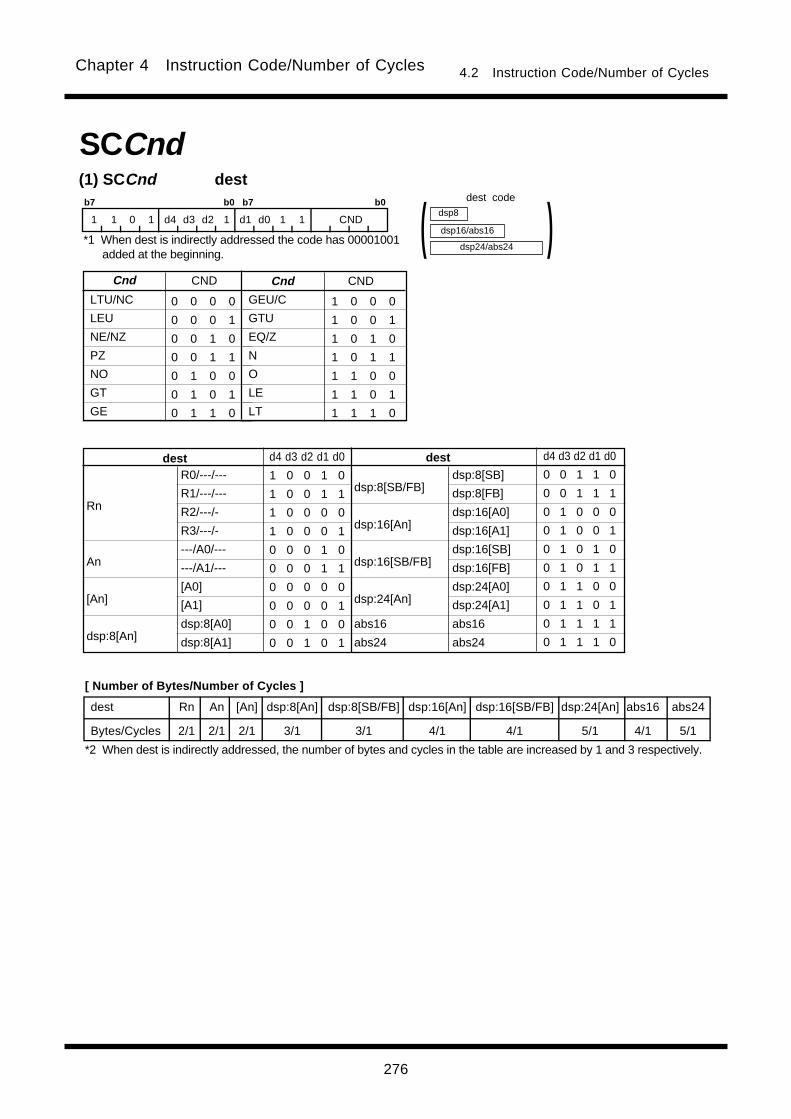
276
Chapter 4 Instruction Code/Number of Cycles 4.2 Instruction Code/Number of Cycles
(1) SCCnd dest
SCCnd
GEU/C
GTU
EQ/Z
N
O
LE
LT
LTU/NC
LEU
NE/NZ
PZ
NO
GT
GE
0 0 0 0
0 0 0 1
0 0 1 0
0 0 1 1
0 1 0 0
0 1 0 1
0 1 1 0
Cnd CND Cnd CND
1 0 0 0
1 0 0 1
1 0 1 0
1 0 1 1
1 1 0 0
1 1 0 1
1 1 1 0
b7 b0 b7 b0
1 1 0 1 d4 d3 d2 1 d1 d0 1 1 CND
dsp24/abs24
dsp8
dsp16/abs16 )(
dest Rn An [An] dsp:8[An] dsp:8[SB/FB] dsp:16[An] dsp:16[SB/FB] dsp:24[An] abs16 abs24
Bytes/Cycles 2/1 2/1 2/1 3/1 3/1 4/1 4/1 5/1 4/1 5/1
R0/---/---
R1/---/---
R2/---/-
R3/---/-
---/A0/---
---/A1/---
[A0]
[A1]
dsp:8[A0]
dsp:8[A1]
dsp:8[SB/FB]
dsp:16[An]
dsp:16[SB/FB]
dsp:24[An]
abs16
abs24
Rn
An
[An]
dsp:8[An]
destdest d4 d3 d2 d1 d0
1 0 0 1 0
1 0 0 1 1
1 0 0 0 0
1 0 0 0 1
0 0 0 1 0
0 0 0 1 1
0 0 0 0 0
0 0 0 0 1
0 0 1 0 0
0 0 1 0 1
d4 d3 d2 d1 d0
0 0 1 1 0
0 0 1 1 1
0 1 0 0 0
0 1 0 0 1
0 1 0 1 0
0 1 0 1 1
0 1 1 0 0
0 1 1 0 1
0 1 1 1 1
0 1 1 1 0
dsp:8[SB]
dsp:8[FB]
dsp:16[A0]
dsp:16[A1]
dsp:16[SB]
dsp:16[FB]
dsp:24[A0]
dsp:24[A1]
abs16
abs24
dest code
*1 When dest is indirectly addressed the code has 00001001added at the beginning.
[ Number of Bytes/Number of Cycles ]
*2 When dest is indirectly addressed, the number of bytes and cycles in the table are increased by 1 and 3 respectively.

277
Chapter 4 Instruction Code/Number of Cycles 4.2 Instruction Code/Number of Cycles
.size
.B
.W
SIZE
0
1
b7 b0 b7 b0
1 0 1 1 1 0 0 0 1 1 0 SIZE 0 0 1 1
SCMPU(1) SCMPU.size
*1 m denotes the number of transfers performed.
[ Number of Bytes/Number of Cycles ]
Contents match andthe instruction is terminated
Contents do not match andthe instruction is terminated
Size specifier Bytes/Cycles
.B 2/6+3m 2/6+3m
.W 2/6+1.5m 2/9+1.5m
.W 2/8+1.5m 2/10+1.5m
Remark
The last 0 (null) is the 8 high-order bits
of word
The last 0(null) is the 8 low-order bits
of word

278
Chapter 4 Instruction Code/Number of Cycles 4.2 Instruction Code/Number of Cycles
SHA(1) SHA.size #IMM, dest
.size
.B
.W
SIZE
0
1
b7 b0 b7 b0
1 1 1 1 d4 d3 d2 SIZE d1 d0 0 0 IMM4
R0L/R0/---
R1L/R1/---
R0H/R2/-
R1H/R3/-
A0
A1
[A0]
[A1]
dsp:8[A0]
dsp:8[A1]
dsp:8[SB/FB]
dsp:16[An]
dsp:16[SB/FB]
dsp:24[An]
abs16
abs24
Rn
An
[An]
dsp:8[An]
destdest d4 d3 d2 d1 d0
1 0 0 1 0
1 0 0 1 1
1 0 0 0 0
1 0 0 0 1
0 0 0 1 0
0 0 0 1 1
0 0 0 0 0
0 0 0 0 1
0 0 1 0 0
0 0 1 0 1
d4 d3 d2 d1 d0
0 0 1 1 0
0 0 1 1 1
0 1 0 0 0
0 1 0 0 1
0 1 0 1 0
0 1 0 1 1
0 1 1 0 0
0 1 1 0 1
0 1 1 1 1
0 1 1 1 0
dsp24/abs24
dsp8
dsp16/abs16 )(
dsp:8[SB]
dsp:8[FB]
dsp:16[A0]
dsp:16[A1]
dsp:16[SB]
dsp:16[FB]
dsp:24[A0]
dsp:24[A1]
abs16
abs24
*2 m denotes the number of shifts performed.
+1
+2
+3
+4
+5
+6
+7
+8
#IMM#IMM IMM4
0 0 0 0
0 0 0 1
0 0 1 0
0 0 1 1
0 1 0 0
0 1 0 1
0 1 1 0
0 1 1 1
IMM4
1 0 0 0
1 0 0 1
1 0 1 0
1 0 1 1
1 1 0 0
1 1 0 1
1 1 1 0
1 1 1 1
-1
-2
-3
-4
-5
-6
-7
-8
dest code
*1 When dest is indirectly addressed the code has 00001001added at the beginning.
[ Number of Bytes/Number of Cycles ]
*3 When dest is indirectly addressed, the number of bytes and cycles in the table are increased by 1 and 3 respectively.
dest Rn An [An] dsp:8[An] dsp:8[SB/FB] dsp:16[An] dsp:16[SB/FB] dsp:24[An] abs16 abs24
Bytes/Cycles 2/m 2/m 2/2+m 3/2+m 3/2+m 4/2+m 4/2+m 5/2+m 4/2+m 5/2+m
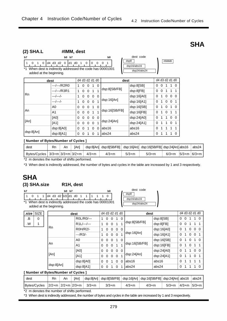
279
Chapter 4 Instruction Code/Number of Cycles 4.2 Instruction Code/Number of Cycles
SHA(3) SHA.size R1H, destb7 b0 b7 b0
1 0 1 1 d4 d3 d2 SIZE d1 d0 1 1 1 1 1 0
R0L/R0/---
R1L/---/---
R0H/R2/-
---/R3/-
A0
A1
[A0]
[A1]
dsp:8[A0]
dsp:8[A1]
dsp:8[SB/FB]
dsp:16[An]
dsp:16[SB/FB]
dsp:24[An]
abs16
abs24
Rn
An
[An]
dsp:8[An]
destdest d4 d3 d2 d1 d0
1 0 0 1 0
1 0 0 1 1
1 0 0 0 0
1 0 0 0 1
0 0 0 1 0
0 0 0 1 1
0 0 0 0 0
0 0 0 0 1
0 0 1 0 0
0 0 1 0 1
d4 d3 d2 d1 d0
0 0 1 1 0
0 0 1 1 1
0 1 0 0 0
0 1 0 0 1
0 1 0 1 0
0 1 0 1 1
0 1 1 0 0
0 1 1 0 1
0 1 1 1 1
0 1 1 1 0
dsp24/abs24
dsp8
dsp16/abs16 )(dsp:8[SB]
dsp:8[FB]
dsp:16[A0]
dsp:16[A1]
dsp:16[SB]
dsp:16[FB]
dsp:24[A0]
dsp:24[A1]
abs16
abs24
.size
.B
.W
SIZE
0
1
SHA(2) SHA.L #IMM, destb7 b0 b7 b0
1 0 1 0 d4 d3 d2 0 d1 d0 1 0 0 0 0 1
dsp24/abs24
dsp8
dsp16/abs16 )(---/---/R2R0
---/---/R3R1
---/---/-
---/---/-
A0
A1
[A0]
[A1]
dsp:8[A0]
dsp:8[A1]
dsp:8[SB/FB]
dsp:16[An]
dsp:16[SB/FB]
dsp:24[An]
abs16
abs24
Rn
An
[An]
dsp:8[An]
destdest d4 d3 d2 d1 d0
1 0 0 1 0
1 0 0 1 1
1 0 0 0 0
1 0 0 0 1
0 0 0 1 0
0 0 0 1 1
0 0 0 0 0
0 0 0 0 1
0 0 1 0 0
0 0 1 0 1
d4 d3 d2 d1 d0
0 0 1 1 0
0 0 1 1 1
0 1 0 0 0
0 1 0 0 1
0 1 0 1 0
0 1 0 1 1
0 1 1 0 0
0 1 1 0 1
0 1 1 1 1
0 1 1 1 0
dsp:8[SB]
dsp:8[FB]
dsp:16[A0]
dsp:16[A1]
dsp:16[SB]
dsp:16[FB]
dsp:24[A0]
dsp:24[A1]
abs16
abs24
#IMM8
*2 m denotes the number of shifts performed.
dest code
*1 When dest is indirectly addressed the code has 00001001added at the beginning.
[ Number of Bytes/Number of Cycles ]
*3 When dest is indirectly addressed, the number of bytes and cycles in the table are increased by 1 and 3 respectively.
dest code
*1 When dest is indirectly addressed the code has 00001001added at the beginning.
[ Number of Bytes/Number of Cycles ]
*2 m denotes the number of shifts performed.*3 When dest is indirectly addressed, the number of bytes and cycles in the table are increased by 1 and 3 respectively.
dest Rn An [An] dsp:8[An] dsp:8[SB/FB] dsp:16[An] dsp:16[SB/FB] dsp:24[An] abs16 abs24
Bytes/Cycles 3/3+m 3/3+m 3/2+m 4/3+m 4/3+m 5/3+m 5/3+m 6/3+m 5/3+m 6/3+m
dest Rn An [An] dsp:8[An] dsp:8[SB/FB] dsp:16[An] dsp:16[SB/FB] dsp:24[An] abs16 abs24
Bytes/Cycles 2/2+m 2/2+m 2/3+m 3/3+m 3/3+m 4/3+m 4/3+m 5/3+m 4/3+m 5/3+m
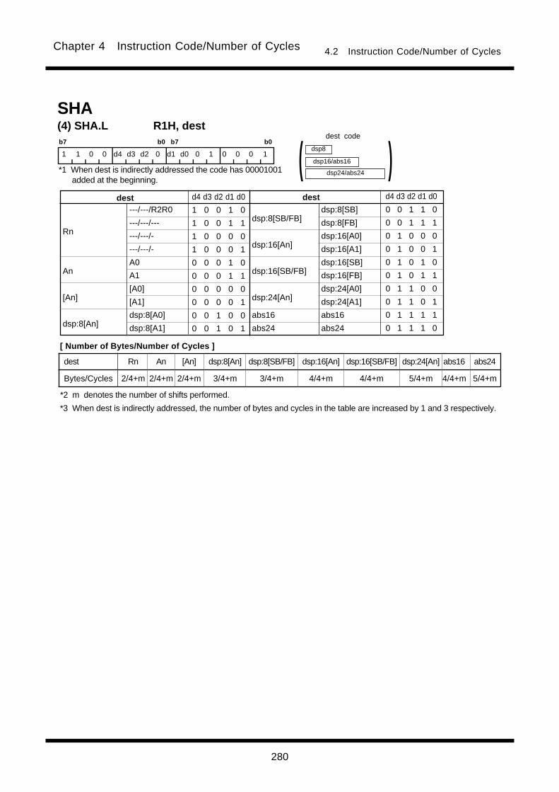
280
Chapter 4 Instruction Code/Number of Cycles 4.2 Instruction Code/Number of Cycles
SHA(4) SHA.L R1H, destb7 b0 b7 b0
1 1 0 0 d4 d3 d2 0 d1 d0 0 1 0 0 0 1
dsp24/abs24
dsp8
dsp16/abs16 )(---/---/R2R0
---/---/---
---/---/-
---/---/-
A0
A1
[A0]
[A1]
dsp:8[A0]
dsp:8[A1]
dsp:8[SB/FB]
dsp:16[An]
dsp:16[SB/FB]
dsp:24[An]
abs16
abs24
Rn
An
[An]
dsp:8[An]
destdest d4 d3 d2 d1 d0
1 0 0 1 0
1 0 0 1 1
1 0 0 0 0
1 0 0 0 1
0 0 0 1 0
0 0 0 1 1
0 0 0 0 0
0 0 0 0 1
0 0 1 0 0
0 0 1 0 1
d4 d3 d2 d1 d0
0 0 1 1 0
0 0 1 1 1
0 1 0 0 0
0 1 0 0 1
0 1 0 1 0
0 1 0 1 1
0 1 1 0 0
0 1 1 0 1
0 1 1 1 1
0 1 1 1 0
dsp:8[SB]
dsp:8[FB]
dsp:16[A0]
dsp:16[A1]
dsp:16[SB]
dsp:16[FB]
dsp:24[A0]
dsp:24[A1]
abs16
abs24
dest code
*1 When dest is indirectly addressed the code has 00001001added at the beginning.
[ Number of Bytes/Number of Cycles ]
*2 m denotes the number of shifts performed.
*3 When dest is indirectly addressed, the number of bytes and cycles in the table are increased by 1 and 3 respectively.
dest Rn An [An] dsp:8[An] dsp:8[SB/FB] dsp:16[An] dsp:16[SB/FB] dsp:24[An] abs16 abs24
Bytes/Cycles 2/4+m 2/4+m 2/4+m 3/4+m 3/4+m 4/4+m 4/4+m 5/4+m 4/4+m 5/4+m
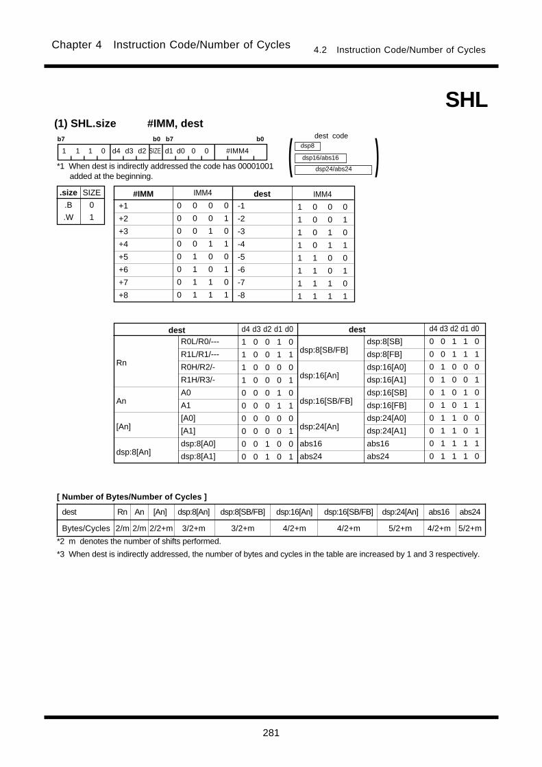
281
Chapter 4 Instruction Code/Number of Cycles 4.2 Instruction Code/Number of Cycles
+1
+2
+3
+4
+5
+6
+7
+8
dest#IMM IMM4
0 0 0 0
0 0 0 1
0 0 1 0
0 0 1 1
0 1 0 0
0 1 0 1
0 1 1 0
0 1 1 1
IMM4
1 0 0 0
1 0 0 1
1 0 1 0
1 0 1 1
1 1 0 0
1 1 0 1
1 1 1 0
1 1 1 1
-1
-2
-3
-4
-5
-6
-7
-8
SHL(1) SHL.size #IMM, dest
.size
.B
.W
SIZE
0
1
b7 b0 b7 b0
1 1 1 0 d4 d3 d2 SIZE d1 d0 0 0 #IMM4
R0L/R0/---
R1L/R1/---
R0H/R2/-
R1H/R3/-
A0
A1
[A0]
[A1]
dsp:8[A0]
dsp:8[A1]
dsp:8[SB/FB]
dsp:16[An]
dsp:16[SB/FB]
dsp:24[An]
abs16
abs24
Rn
An
[An]
dsp:8[An]
destdest d4 d3 d2 d1 d0
1 0 0 1 0
1 0 0 1 1
1 0 0 0 0
1 0 0 0 1
0 0 0 1 0
0 0 0 1 1
0 0 0 0 0
0 0 0 0 1
0 0 1 0 0
0 0 1 0 1
d4 d3 d2 d1 d0
0 0 1 1 0
0 0 1 1 1
0 1 0 0 0
0 1 0 0 1
0 1 0 1 0
0 1 0 1 1
0 1 1 0 0
0 1 1 0 1
0 1 1 1 1
0 1 1 1 0
dsp24/abs24
dsp8
dsp16/abs16 )(
dsp:8[SB]
dsp:8[FB]
dsp:16[A0]
dsp:16[A1]
dsp:16[SB]
dsp:16[FB]
dsp:24[A0]
dsp:24[A1]
abs16
abs24
dest code
*1 When dest is indirectly addressed the code has 00001001added at the beginning.
[ Number of Bytes/Number of Cycles ]
*2 m denotes the number of shifts performed.
*3 When dest is indirectly addressed, the number of bytes and cycles in the table are increased by 1 and 3 respectively.
dest Rn An [An] dsp:8[An] dsp:8[SB/FB] dsp:16[An] dsp:16[SB/FB] dsp:24[An] abs16 abs24
Bytes/Cycles 2/m 2/m 2/2+m 3/2+m 3/2+m 4/2+m 4/2+m 5/2+m 4/2+m 5/2+m
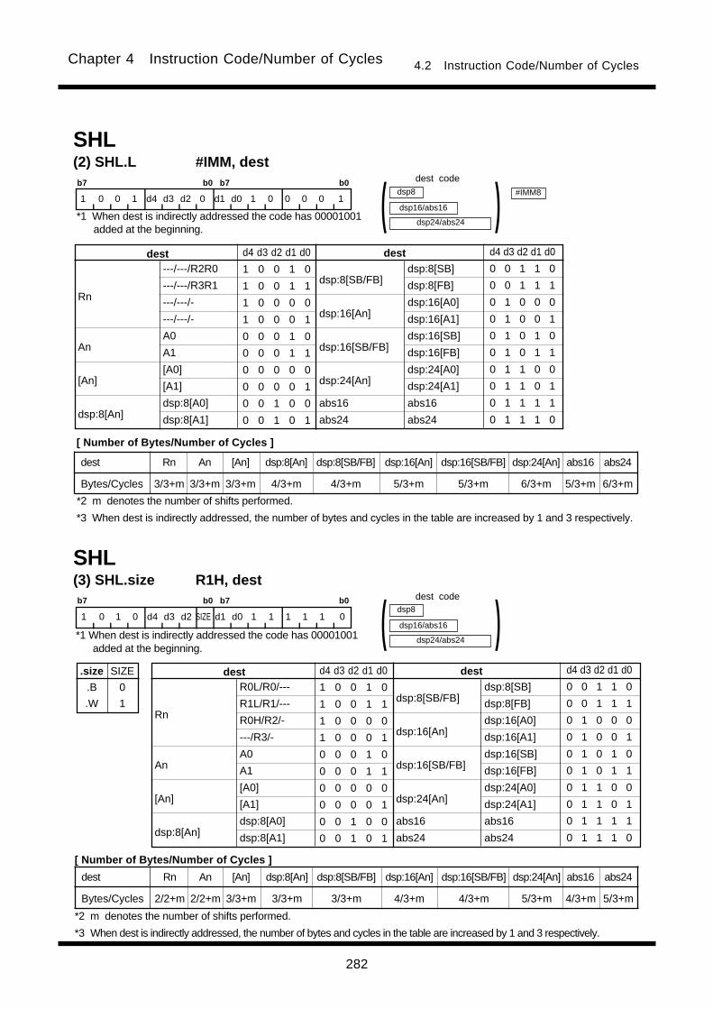
282
Chapter 4 Instruction Code/Number of Cycles 4.2 Instruction Code/Number of Cycles
SHL(2) SHL.L #IMM, destb7 b0 b7 b0
1 0 0 1 d4 d3 d2 0 d1 d0 1 0 0 0 0 1
dsp24/abs24
dsp8
dsp16/abs16 )(---/---/R2R0
---/---/R3R1
---/---/-
---/---/-
A0
A1
[A0]
[A1]
dsp:8[A0]
dsp:8[A1]
dsp:8[SB/FB]
dsp:16[An]
dsp:16[SB/FB]
dsp:24[An]
abs16
abs24
Rn
An
[An]
dsp:8[An]
destdest d4 d3 d2 d1 d0
1 0 0 1 0
1 0 0 1 1
1 0 0 0 0
1 0 0 0 1
0 0 0 1 0
0 0 0 1 1
0 0 0 0 0
0 0 0 0 1
0 0 1 0 0
0 0 1 0 1
d4 d3 d2 d1 d0
0 0 1 1 0
0 0 1 1 1
0 1 0 0 0
0 1 0 0 1
0 1 0 1 0
0 1 0 1 1
0 1 1 0 0
0 1 1 0 1
0 1 1 1 1
0 1 1 1 0
dsp:8[SB]
dsp:8[FB]
dsp:16[A0]
dsp:16[A1]
dsp:16[SB]
dsp:16[FB]
dsp:24[A0]
dsp:24[A1]
abs16
abs24
#IMM8
SHL(3) SHL.size R1H, destb7 b0 b7 b0
1 0 1 0 d4 d3 d2 SIZE d1 d0 1 1 1 1 1 0
R0L/R0/---
R1L/R1/---
R0H/R2/-
---/R3/-
A0
A1
[A0]
[A1]
dsp:8[A0]
dsp:8[A1]
dsp:8[SB/FB]
dsp:16[An]
dsp:16[SB/FB]
dsp:24[An]
abs16
abs24
Rn
An
[An]
dsp:8[An]
destdest d4 d3 d2 d1 d0
1 0 0 1 0
1 0 0 1 1
1 0 0 0 0
1 0 0 0 1
0 0 0 1 0
0 0 0 1 1
0 0 0 0 0
0 0 0 0 1
0 0 1 0 0
0 0 1 0 1
d4 d3 d2 d1 d0
0 0 1 1 0
0 0 1 1 1
0 1 0 0 0
0 1 0 0 1
0 1 0 1 0
0 1 0 1 1
0 1 1 0 0
0 1 1 0 1
0 1 1 1 1
0 1 1 1 0
dsp24/abs24
dsp8
dsp16/abs16 )(dsp:8[SB]
dsp:8[FB]
dsp:16[A0]
dsp:16[A1]
dsp:16[SB]
dsp:16[FB]
dsp:24[A0]
dsp:24[A1]
abs16
abs24
.size
.B
.W
SIZE
0
1
dest code
*1 When dest is indirectly addressed the code has 00001001added at the beginning.
[ Number of Bytes/Number of Cycles ]
*2 m denotes the number of shifts performed.
*3 When dest is indirectly addressed, the number of bytes and cycles in the table are increased by 1 and 3 respectively.
dest code
*1 When dest is indirectly addressed the code has 00001001added at the beginning.
[ Number of Bytes/Number of Cycles ]
*2 m denotes the number of shifts performed.
*3 When dest is indirectly addressed, the number of bytes and cycles in the table are increased by 1 and 3 respectively.
dest Rn An [An] dsp:8[An] dsp:8[SB/FB] dsp:16[An] dsp:16[SB/FB] dsp:24[An] abs16 abs24
Bytes/Cycles 3/3+m 3/3+m 3/3+m 4/3+m 4/3+m 5/3+m 5/3+m 6/3+m 5/3+m 6/3+m
dest Rn An [An] dsp:8[An] dsp:8[SB/FB] dsp:16[An] dsp:16[SB/FB] dsp:24[An] abs16 abs24
Bytes/Cycles 2/2+m 2/2+m 3/3+m 3/3+m 3/3+m 4/3+m 4/3+m 5/3+m 4/3+m 5/3+m
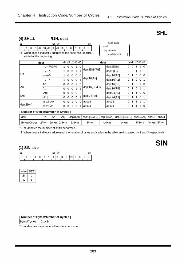
283
Chapter 4 Instruction Code/Number of Cycles 4.2 Instruction Code/Number of Cycles
SIN(1) SIN.sizeb7 b0 b7 b0
1 0 1 1 0 0 1 0 1 0 0 SIZE 0 0 1 1
.size
.B
.W
SIZE
0
1
Bytes/Cycles 2/1+2m
SHL(4) SHL.L R1H, destb7 b0 b7 b0
1 1 0 0 d4 d3 d2 0 d1 d0 0 0 0 0 0 1
dsp24/abs24
dsp8
dsp16/abs16 )(---/---/R2R0
---/---/---
---/---/-
---/---/-
A0
A1
[A0]
[A1]
dsp:8[A0]
dsp:8[A1]
dsp:8[SB/FB]
dsp:16[An]
dsp:16[SB/FB]
dsp:24[An]
abs16
abs24
Rn
An
[An]
dsp:8[An]
destdest d4 d3 d2 d1 d0
1 0 0 1 0
1 0 0 1 1
1 0 0 0 0
1 0 0 0 1
0 0 0 1 0
0 0 0 1 1
0 0 0 0 0
0 0 0 0 1
0 0 1 0 0
0 0 1 0 1
d4 d3 d2 d1 d0
0 0 1 1 0
0 0 1 1 1
0 1 0 0 0
0 1 0 0 1
0 1 0 1 0
0 1 0 1 1
0 1 1 0 0
0 1 1 0 1
0 1 1 1 1
0 1 1 1 0
dsp:8[SB]
dsp:8[FB]
dsp:16[A0]
dsp:16[A1]
dsp:16[SB]
dsp:16[FB]
dsp:24[A0]
dsp:24[A1]
abs16
abs24
dest code
*1 When dest is indirectly addressed the code has 00001001added at the beginning.
[ Number of Bytes/Number of Cycles ]
*2 m denotes the number of shifts performed.
*3 When dest is indirectly addressed, the number of bytes and cycles in the table are increased by 1 and 3 respectively.
[ Number of Bytes/Number of Cycles ]
*1 m denotes the number of transfers performed.
dest Rn An [An] dsp:8[An] dsp:8[SB/FB] dsp:16[An] dsp:16[SB/FB] dsp:24[An] abs16 abs24
Bytes/Cycles 2/4+m 2/4+m 2/4+m 3/4+m 3/4+m 4/4+m 4/4+m 5/4+m 4/4+m 5/4+m

284
Chapter 4 Instruction Code/Number of Cycles 4.2 Instruction Code/Number of Cycles
SMOVB(1) SMOVB.sizeb7 b0 b7 b0
1 0 1 1 0 1 1 0 1 0 0 SIZE 0 0 1 1
.size
.B
.W
SIZE
0
1
Bytes/Cycles 2/1+2m
SMOVF(1) SMOVF.sizeb7 b0 b7 b0
1 0 1 1 0 0 0 0 1 0 0 SIZE 0 0 1 1
.size
.B
.W
SIZE
0
1
Bytes/Cycles 2/1+2m
[ Number of Bytes/Number of Cycles ]
*1 m denotes the number of transfers performed.
[ Number of Bytes/Number of Cycles ]
*1 m denotes the number of transfers performed.
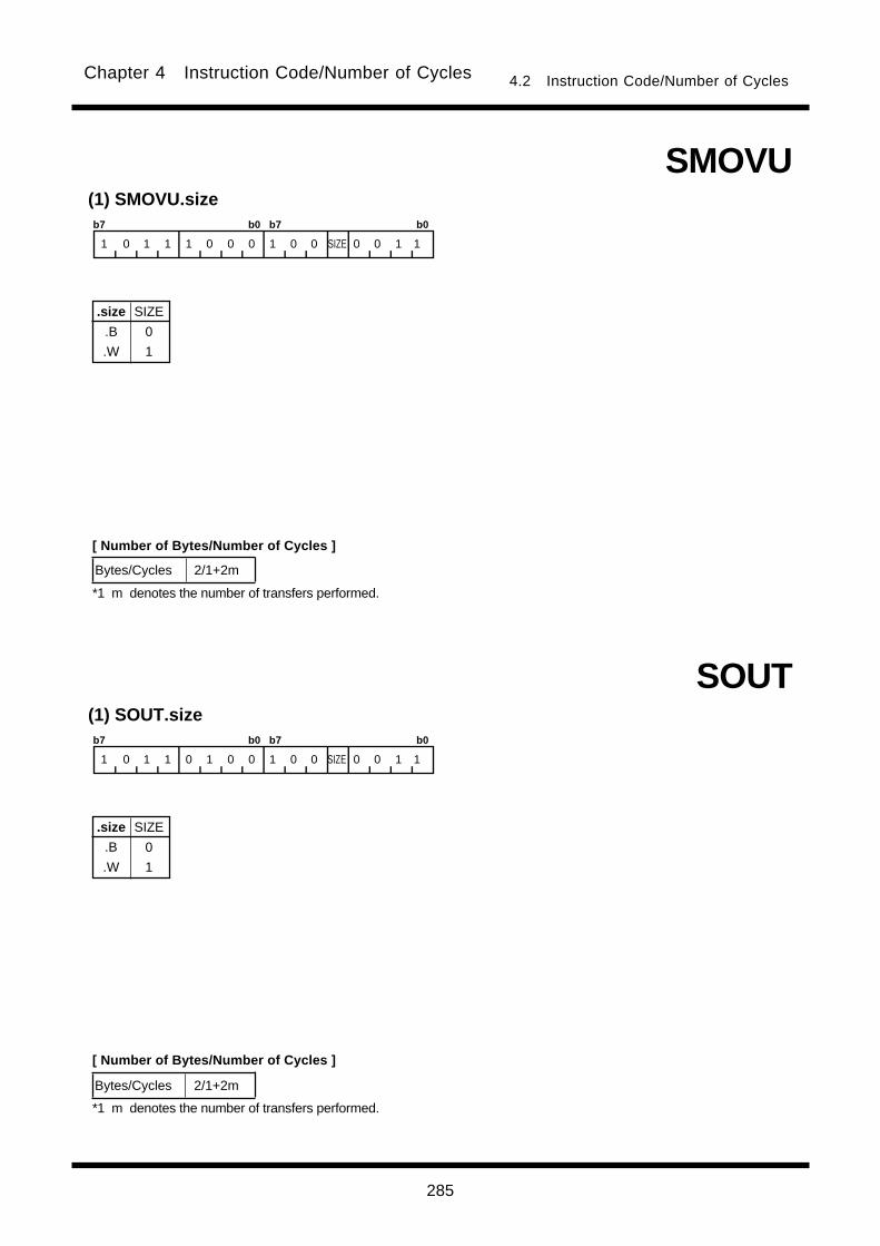
285
Chapter 4 Instruction Code/Number of Cycles 4.2 Instruction Code/Number of Cycles
SMOVU(1) SMOVU.sizeb7 b0 b7 b0
1 0 1 1 1 0 0 0 1 0 0 SIZE 0 0 1 1
.size
.B
.W
SIZE
0
1
Bytes/Cycles 2/1+2m
[ Number of Bytes/Number of Cycles ]
*1 m denotes the number of transfers performed.
SOUT(1) SOUT.sizeb7 b0 b7 b0
1 0 1 1 0 1 0 0 1 0 0 SIZE 0 0 1 1
.size
.B
.W
SIZE
0
1
Bytes/Cycles 2/1+2m
[ Number of Bytes/Number of Cycles ]
*1 m denotes the number of transfers performed.
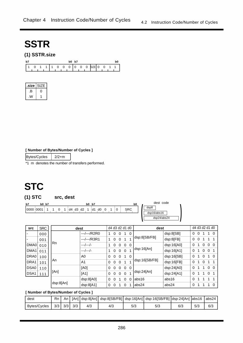
286
Chapter 4 Instruction Code/Number of Cycles 4.2 Instruction Code/Number of Cycles
SSTR(1) SSTR.sizeb7 b0 b7 b0
1 0 1 1 1 0 0 0 0 0 0 SIZE 0 0 1 1
.size
.B
.W
SIZE
0
1
Bytes/Cycles 2/2+m
[ Number of Bytes/Number of Cycles ]
*1 m denotes the number of transfers performed.
(1) STC src, dest
dest Rn An [An] dsp:8[An] dsp:8[SB/FB] dsp:16[An] dsp:16[SB/FB] dsp:24[An] abs16 abs24
Bytes/Cycles 3/3 3/3 3/3 4/3 4/3 5/3 5/3 6/3 5/3 6/3
-
-
DMA0
DMA1
DRA0
DRA1
DSA0
DSA1
src SRC
000
001
010
011
100
101
110
111
dsp24/abs24
dsp8
dsp16/abs16 )(STC
---/---/R2R0
---/---/R3R1
---/---/-
---/---/-
A0
A1
[A0]
[A1]
dsp:8[A0]
dsp:8[A1]
dsp:8[SB/FB]
dsp:16[An]
dsp:16[SB/FB]
dsp:24[An]
abs16
abs24
Rn
An
[An]
dsp:8[An]
destdest d4 d3 d2 d1 d0
1 0 0 1 0
1 0 0 1 1
1 0 0 0 0
1 0 0 0 1
0 0 0 1 0
0 0 0 1 1
0 0 0 0 0
0 0 0 0 1
0 0 1 0 0
0 0 1 0 1
d4 d3 d2 d1 d0
0 0 1 1 0
0 0 1 1 1
0 1 0 0 0
0 1 0 0 1
0 1 0 1 0
0 1 0 1 1
0 1 1 0 0
0 1 1 0 1
0 1 1 1 1
0 1 1 1 0
dsp:8[SB]
dsp:8[FB]
dsp:16[A0]
dsp:16[A1]
dsp:16[SB]
dsp:16[FB]
dsp:24[A0]
dsp:24[A1]
abs16
abs24
b7 b0 b7 b0 b7 b0
0000 0001 1 1 0 1 d4 d3 d2 1 d1 d0 0 1 0 SRC
[ Number of Bytes/Number of Cycles ]
dest code

287
Chapter 4 Instruction Code/Number of Cycles 4.2 Instruction Code/Number of Cycles
(3) STC src, destb7 b0 b7 b0
1 1 0 1 d4 d3 d2 1 d1 d0 0 1 0 SRC
dest Rn An [An] dsp:8[An] dsp:8[SB/FB] dsp:16[An] dsp:16[SB/FB] dsp:24[An] abs16 abs24
Bytes/Cycles 2/3 2/3 2/3 3/3 3/3 4/3 4/3 5/3 4/3 5/3
INTB
SP
SB
FB
SVP
VCT
-
ISP
src SRC
000
001
010
011
100
101
110
111
dsp24/abs24
dsp8
dsp16/abs16 )(STC
---/---/R2R0
---/---/R3R1
---/---/-
---/---/-
A0
A1
[A0]
[A1]
dsp:8[A0]
dsp:8[A1]
dsp:8[SB/FB]
dsp:16[An]
dsp:16[SB/FB]
dsp:24[An]
abs16
abs24
Rn
An
[An]
dsp:8[An]
destdest d4 d3 d2 d1 d0
1 0 0 1 0
1 0 0 1 1
1 0 0 0 0
1 0 0 0 1
0 0 0 1 0
0 0 0 1 1
0 0 0 0 0
0 0 0 0 1
0 0 1 0 0
0 0 1 0 1
d4 d3 d2 d1 d0
0 0 1 1 0
0 0 1 1 1
0 1 0 0 0
0 1 0 0 1
0 1 0 1 0
0 1 0 1 1
0 1 1 0 0
0 1 1 0 1
0 1 1 1 1
0 1 1 1 0
dsp:8[SB]
dsp:8[FB]
dsp:16[A0]
dsp:16[A1]
dsp:16[SB]
dsp:16[FB]
dsp:24[A0]
dsp:24[A1]
abs16
abs24
(2) STC src, dest
dest Rn An [An] dsp:8[An] dsp:8[SB/FB] dsp:16[An] dsp:16[SB/FB] dsp:24[An] abs16 abs24
Bytes/Cycles 3/2 3/2 3/2 4/2 4/2 5/2 5/2 6/2 5/2 6/2
DCT0
DCT1
FLG
SVF
DRC0
DRC1
DMD0
DMD1
src SRC
000
001
010
011
100
101
110
111
dsp24/abs24
dsp8
dsp16/abs16 )(STC
---/R0/---
---/R1/---
---/R2/-
---/R3/-
A0
A1
[A0]
[A1]
dsp:8[A0]
dsp:8[A1]
dsp:8[SB/FB]
dsp:16[An]
dsp:16[SB/FB]
dsp:24[An]
abs16
abs24
Rn
An
[An]
dsp:8[An]
destdest d4 d3 d2 d1 d0
1 0 0 1 0
1 0 0 1 1
1 0 0 0 0
1 0 0 0 1
0 0 0 1 0
0 0 0 1 1
0 0 0 0 0
0 0 0 0 1
0 0 1 0 0
0 0 1 0 1
d4 d3 d2 d1 d0
0 0 1 1 0
0 0 1 1 1
0 1 0 0 0
0 1 0 0 1
0 1 0 1 0
0 1 0 1 1
0 1 1 0 0
0 1 1 0 1
0 1 1 1 1
0 1 1 1 0
dsp:8[SB]
dsp:8[FB]
dsp:16[A0]
dsp:16[A1]
dsp:16[SB]
dsp:16[FB]
dsp:24[A0]
dsp:24[A1]
abs16
abs24
b7 b0 b7 b0 b7 b0
0000 0001 1 1 0 1 d4 d3 d2 1 d1 d0 0 1 1 SRC
dest code
[ Number of Bytes/Number of Cycles ]
dest code
[ Number of Bytes/Number of Cycles ]

288
Chapter 4 Instruction Code/Number of Cycles 4.2 Instruction Code/Number of Cycles
STCTX(1) STCTX abs16, abs24b7 b0 b7 b0
1 0 1 1 0 1 1 0 1 1 0 1 0 0 1 1
Bytes/Cycles 7/10+2m
abs24abs16
STNZ(1) STNZ.size #IMM, dest
.size
.B
.W
SIZE
0
1
b7 b0 b7 b0
1 0 0 1 d4 d3 d2 SIZE d1 d0 0 1 1 1 1 1
dest Rn An [An] dsp:8[An] dsp:8[SB/FB] dsp:16[An] dsp:16[SB/FB] dsp:24[An] abs16 abs24
Bytes/Cycles 3/2 3/2 3/2 4/2 4/2 5/2 5/2 6/2 5/2 6/2
R0L/R0/---
R1L/R1/---
R0H/R2/-
R1H/R3/-
A0
A1
[A0]
[A1]
dsp:8[A0]
dsp:8[A1]
dsp:8[SB/FB]
dsp:16[An]
dsp:16[SB/FB]
dsp:24[An]
abs16
abs24
Rn
An
[An]
dsp:8[An]
destdest d4 d3 d2 d1 d0
1 0 0 1 0
1 0 0 1 1
1 0 0 0 0
1 0 0 0 1
0 0 0 1 0
0 0 0 1 1
0 0 0 0 0
0 0 0 0 1
0 0 1 0 0
0 0 1 0 1
d4 d3 d2 d1 d0
0 0 1 1 0
0 0 1 1 1
0 1 0 0 0
0 1 0 0 1
0 1 0 1 0
0 1 0 1 1
0 1 1 0 0
0 1 1 0 1
0 1 1 1 1
0 1 1 1 0
dsp24/abs24
dsp8
dsp16/abs16 )(dsp:8[SB]
dsp:8[FB]
dsp:16[A0]
dsp:16[A1]
dsp:16[SB]
dsp:16[FB]
dsp:24[A0]
dsp:24[A1]
abs16
abs24
#IMM8
#IMM16
[ Number of Bytes/Number of Cycles ]
*1 m denotes the number of transfers performed.
dest code
*1 When dest is indirectly addressed,the code has 00001001added at the beginning.
[ Number of Bytes/Number of Cycles ]
*2 When dest is indirectly addressed, the number of bytes and cycles in the table are increased by 1 and 3 respectively.*3 When (.W) is specified for the size specifier(.size) the number of bytes in the table is increased by 1.

289
Chapter 4 Instruction Code/Number of Cycles 4.2 Instruction Code/Number of Cycles
STZX(1) STZX.size #IMM1, #IMM2, dest
.size
.B
.W
SIZE
0
1
b7 b0 b7 b0
1 0 0 1 d4 d3 d2 SIZE d1 d0 1 1 1 1 1 1
dest Rn An [An] dsp:8[An] dsp:8[SB/FB] dsp:16[An] dsp:16[SB/FB] dsp:24[An] abs16 abs24
Bytes/Cycles 4/3 4/3 4/3 5/3 5/3 6/3 6/3 7/3 6/3 7/3
R0L/R0/---
R1L/R1/---
R0H/R2/-
R1H/R3/-
A0
A1
[A0]
[A1]
dsp:8[A0]
dsp:8[A1]
dsp:8[SB/FB]
dsp:16[An]
dsp:16[SB/FB]
dsp:24[An]
abs16
abs24
Rn
An
[An]
dsp:8[An]
destdest d4 d3 d2 d1 d0
1 0 0 1 0
1 0 0 1 1
1 0 0 0 0
1 0 0 0 1
0 0 0 1 0
0 0 0 1 1
0 0 0 0 0
0 0 0 0 1
0 0 1 0 0
0 0 1 0 1
d4 d3 d2 d1 d0
0 0 1 1 0
0 0 1 1 1
0 1 0 0 0
0 1 0 0 1
0 1 0 1 0
0 1 0 1 1
0 1 1 0 0
0 1 1 0 1
0 1 1 1 1
0 1 1 1 0
dsp24/abs24
dsp8
dsp16/abs16 )(dsp:8[SB]
dsp:8[FB]
dsp:16[A0]
dsp:16[A1]
dsp:16[SB]
dsp:16[FB]
dsp:24[A0]
dsp:24[A1]
abs16
abs24
#IMM8-1
#IMM16-1
#IMM8-2
#IMM16-2
STZ(1) STZ.size #IMM, dest
dest Rn An [An] dsp:8[An] dsp:8[SB/FB] dsp:16[An] dsp:16[SB/FB] dsp:24[An] abs16 abs24
Bytes/Cycles 3/2 3/2 3/2 4/2 4/2 5/2 5/2 6/2 5/2 6/2
R0L/R0/---
R1L/R1/---
R0H/R2/-
R1H/R3/-
A0
A1
[A0]
[A1]
dsp:8[A0]
dsp:8[A1]
dsp:8[SB/FB]
dsp:16[An]
dsp:16[SB/FB]
dsp:24[An]
abs16
abs24
Rn
An
[An]
dsp:8[An]
destdest d4 d3 d2 d1 d0
1 0 0 1 0
1 0 0 1 1
1 0 0 0 0
1 0 0 0 1
0 0 0 1 0
0 0 0 1 1
0 0 0 0 0
0 0 0 0 1
0 0 1 0 0
0 0 1 0 1
d4 d3 d2 d1 d0
0 0 1 1 0
0 0 1 1 1
0 1 0 0 0
0 1 0 0 1
0 1 0 1 0
0 1 0 1 1
0 1 1 0 0
0 1 1 0 1
0 1 1 1 1
0 1 1 1 0
dsp24/abs24
dsp8
dsp16/abs16 )(dsp:8[SB]
dsp:8[FB]
dsp:16[A0]
dsp:16[A1]
dsp:16[SB]
dsp:16[FB]
dsp:24[A0]
dsp:24[A1]
abs16
abs24
b7 b0 b7 b0
1 0 0 1 d4 d3 d2 SIZE d1 d0 0 0 1 1 1 1
.size
.B
.W
SIZE
0
1
#IMM8
#IMM16
dest code
*1 When dest is indirectly addressed the code has 00001001added at the beginning.
[ Number of Bytes/Number of Cycles ]
*2 When dest is indirectly addressed, the number of bytes and cycles in the table are increased by 1 and 3 respectively.*3 When Z flag is 0,the number of cycles in the table is increased by 1.*4 When (.W) is specified for the size specifier(.size) the number of bytes in the table is increased by 1.
dest code
*1 When dest is indirectly addressed the code has 00001001added at the beginning.
[ Number of Bytes/Number of Cycles ]
*2 When dest is indirectly addressed, the number of bytes and cycles in the table are increased by 1 and 3 respectively.*3 When (.W) is specified for the size specifier(.size) the number of bytes in the table is increased by 2.
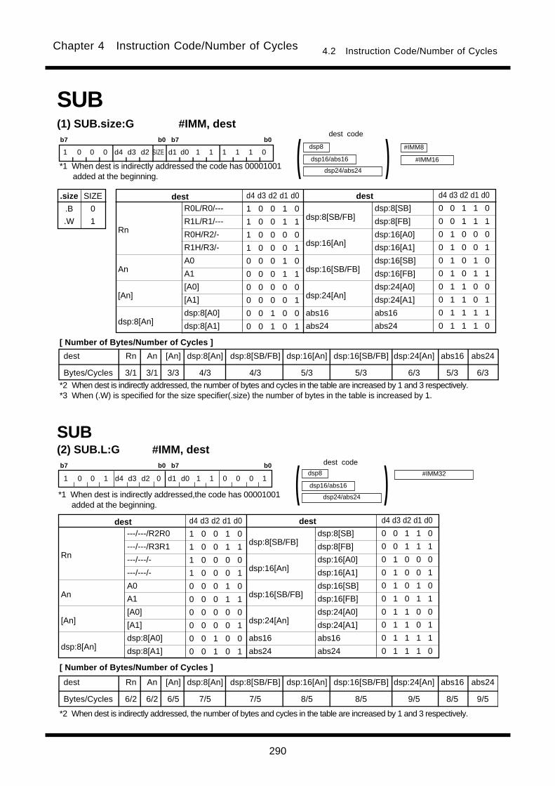
290
Chapter 4 Instruction Code/Number of Cycles 4.2 Instruction Code/Number of Cycles
SUB(1) SUB.size:G #IMM, dest
.size
.B
.W
SIZE
0
1
b7 b0 b7 b0
1 0 0 0 d4 d3 d2 SIZE d1 d0 1 1 1 1 1 0
dest Rn An [An] dsp:8[An] dsp:8[SB/FB] dsp:16[An] dsp:16[SB/FB] dsp:24[An] abs16 abs24
Bytes/Cycles 3/1 3/1 3/3 4/3 4/3 5/3 5/3 6/3 5/3 6/3
R0L/R0/---
R1L/R1/---
R0H/R2/-
R1H/R3/-
A0
A1
[A0]
[A1]
dsp:8[A0]
dsp:8[A1]
dsp:8[SB/FB]
dsp:16[An]
dsp:16[SB/FB]
dsp:24[An]
abs16
abs24
Rn
An
[An]
dsp:8[An]
destdest d4 d3 d2 d1 d0
1 0 0 1 0
1 0 0 1 1
1 0 0 0 0
1 0 0 0 1
0 0 0 1 0
0 0 0 1 1
0 0 0 0 0
0 0 0 0 1
0 0 1 0 0
0 0 1 0 1
d4 d3 d2 d1 d0
0 0 1 1 0
0 0 1 1 1
0 1 0 0 0
0 1 0 0 1
0 1 0 1 0
0 1 0 1 1
0 1 1 0 0
0 1 1 0 1
0 1 1 1 1
0 1 1 1 0
dsp24/abs24
dsp8
dsp16/abs16 )(dsp:8[SB]
dsp:8[FB]
dsp:16[A0]
dsp:16[A1]
dsp:16[SB]
dsp:16[FB]
dsp:24[A0]
dsp:24[A1]
abs16
abs24
#IMM8
#IMM16
SUB(2) SUB.L:G #IMM, destb7 b0 b7 b0
1 0 0 1 d4 d3 d2 0 d1 d0 1 1 0 0 0 1
dest Rn An [An] dsp:8[An] dsp:8[SB/FB] dsp:16[An] dsp:16[SB/FB] dsp:24[An] abs16 abs24
Bytes/Cycles 6/2 6/2 6/5 7/5 7/5 8/5 8/5 9/5 8/5 9/5
---/---/R2R0
---/---/R3R1
---/---/-
---/---/-
A0
A1
[A0]
[A1]
dsp:8[A0]
dsp:8[A1]
dsp:8[SB/FB]
dsp:16[An]
dsp:16[SB/FB]
dsp:24[An]
abs16
abs24
Rn
An
[An]
dsp:8[An]
destdest d4 d3 d2 d1 d0
1 0 0 1 0
1 0 0 1 1
1 0 0 0 0
1 0 0 0 1
0 0 0 1 0
0 0 0 1 1
0 0 0 0 0
0 0 0 0 1
0 0 1 0 0
0 0 1 0 1
d4 d3 d2 d1 d0
0 0 1 1 0
0 0 1 1 1
0 1 0 0 0
0 1 0 0 1
0 1 0 1 0
0 1 0 1 1
0 1 1 0 0
0 1 1 0 1
0 1 1 1 1
0 1 1 1 0
dsp24/abs24
dsp8
dsp16/abs16 )(dsp:8[SB]
dsp:8[FB]
dsp:16[A0]
dsp:16[A1]
dsp:16[SB]
dsp:16[FB]
dsp:24[A0]
dsp:24[A1]
abs16
abs24
#IMM32
dest code
*1 When dest is indirectly addressed the code has 00001001added at the beginning.
[ Number of Bytes/Number of Cycles ]
*2 When dest is indirectly addressed, the number of bytes and cycles in the table are increased by 1 and 3 respectively.*3 When (.W) is specified for the size specifier(.size) the number of bytes in the table is increased by 1.
dest code
*1 When dest is indirectly addressed,the code has 00001001added at the beginning.
[ Number of Bytes/Number of Cycles ]
*2 When dest is indirectly addressed, the number of bytes and cycles in the table are increased by 1 and 3 respectively.

291
Chapter 4 Instruction Code/Number of Cycles 4.2 Instruction Code/Number of Cycles
dest Rn dsp:8[SB/FB] abs16
Bytes/Cycles 2/1 3/3 4/3
(3) SUB.size:S #IMM, dest
.size
.B
.W
SIZE
0
1
b7 b0
0 0 d1 d0 1 1 1 SIZE
R0L/R0
dsp:8[SB]
dsp:8[FB]
abs16
Rn
dsp:8[SB/FB]
abs16
dest d1 d0
0 0
1 0
1 1
0 1
#IMM8
#IMM16
dsp8
abs16 )(SUB
dest code
*1 When dest is indirectly addressed the code has 00001001added at the beginning.
[ Number of Bytes/Number of Cycles ]
*2 When dest is indirectly addressed, the number of bytes and cycles in the table are increased by 1 and 3 respectively.*3 When (.W) is specified for the size specifier(.size) the number of bytes in the table is increased by 1.

292
Chapter 4 Instruction Code/Number of Cycles 4.2 Instruction Code/Number of Cycles
srcdest Rn An [An] dsp:8[An] dsp:8[SB/FB] dsp:16[An] dsp:16[SB/FB] dsp:24[An] abs16 abs24
Rn 2/1 2/1 2/3 3/3 3/3 4/3 4/3 5/3 4/3 5/3
An 2/1 2/1 2/3 3/3 3/3 4/3 4/3 5/3 4/3 5/3
[An] 2/3 2/3 2/4 3/4 3/4 4/4 4/4 5/4 4/4 5/4
dsp:8[An] 3/3 3/3 3/4 4/4 4/4 5/4 5/4 6/4 5/4 6/4
dsp:8[SB/FB] 3/3 3/3 3/4 4/4 4/4 5/4 5/4 6/4 5/4 6/4
dsp:16[An] 4/3 4/3 4/4 5/4 5/4 6/4 6/4 7/4 6/4 7/4
dsp:16[SB/FB] 4/3 4/3 4/4 5/4 5/4 6/4 6/4 7/4 6/4 7/4
dsp:24[An] 5/3 5/3 5/4 6/4 6/4 7/4 7/4 8/4 7/4 8/4
abs16 4/3 4/3 4/4 5/4 5/4 6/4 6/4 7/4 6/4 7/4
abs24 5/3 5/3 5/4 6/4 6/4 7/4 7/4 8/4 7/4 8/4
(4) SUB.size:G src, dest
.size
.B
.W
SIZE
0
1
b7 b0 b7 b0
1 s4 s3 s2 d4 d3 d2 SIZE d1 d0 s1 s0 1 0 1 0
R0L/R0/---
R1L/R1/---
R0H/R2/-
R1H/R3/-
A0
A1
[A0]
[A1]
dsp:8[A0]
dsp:8[A1]
dsp:8[SB/FB]
dsp:16[An]
dsp:16[SB/FB]
dsp:24[An]
abs16
abs24
Rn
An
[An]
dsp:8[An]
src/destsrc/dest s4 s3 s2 s1 s0d4 d3 d2 d1 d0
1 0 0 1 0
1 0 0 1 1
1 0 0 0 0
1 0 0 0 1
0 0 0 1 0
0 0 0 1 1
0 0 0 0 0
0 0 0 0 1
0 0 1 0 0
0 0 1 0 1
s4 s3 s2 s1 s0d4 d3 d2 d1 d0
0 0 1 1 0
0 0 1 1 1
0 1 0 0 0
0 1 0 0 1
0 1 0 1 0
0 1 0 1 1
0 1 1 0 0
0 1 1 0 1
0 1 1 1 1
0 1 1 1 0
dsp24/abs24
dsp8
dsp16/abs16 )(
dsp:8[SB]
dsp:8[FB]
dsp:16[A0]
dsp:16[A1]
dsp:16[SB]
dsp:16[FB]
dsp:24[A0]
dsp:24[A1]
abs16
abs24
dsp24/abs24
dsp8
dsp16/abs16 )(SUB
src code dest code
*1 For indirect addressing, the following number is added atthe beginning of code:
01000001 when src is indirectly addressed00001001 when dest is indirectly addressed01001001 when src and dest are indirectly addressed
[ Number of Bytes/Number of Cycles ]
*2 When src or dest is indirectly addressed, the number of bytes and cycles in the table are increased by 1 and 3respectively. Also, when src and dest both are indirectly addressed, the number of bytes and cycles in the table areincreased by 1 and 6, respectively.
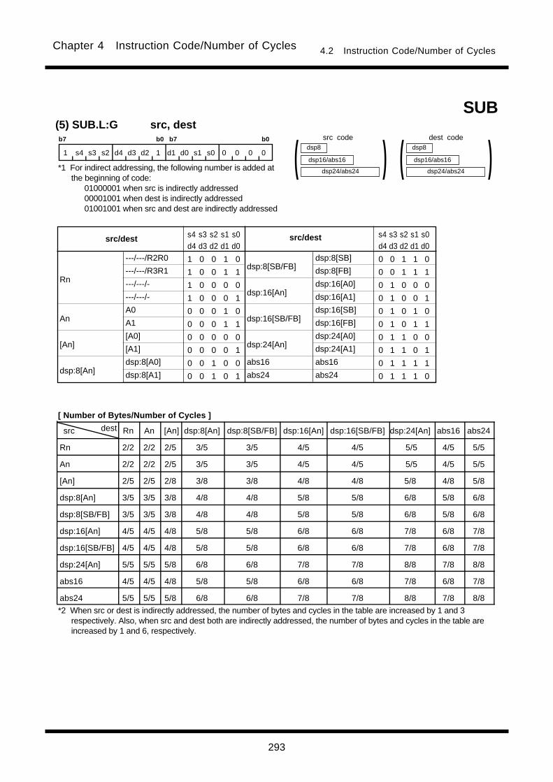
293
Chapter 4 Instruction Code/Number of Cycles 4.2 Instruction Code/Number of Cycles
src dest Rn An [An] dsp:8[An] dsp:8[SB/FB] dsp:16[An] dsp:16[SB/FB] dsp:24[An] abs16 abs24
Rn 2/2 2/2 2/5 3/5 3/5 4/5 4/5 5/5 4/5 5/5
An 2/2 2/2 2/5 3/5 3/5 4/5 4/5 5/5 4/5 5/5
[An] 2/5 2/5 2/8 3/8 3/8 4/8 4/8 5/8 4/8 5/8
dsp:8[An] 3/5 3/5 3/8 4/8 4/8 5/8 5/8 6/8 5/8 6/8
dsp:8[SB/FB] 3/5 3/5 3/8 4/8 4/8 5/8 5/8 6/8 5/8 6/8
dsp:16[An] 4/5 4/5 4/8 5/8 5/8 6/8 6/8 7/8 6/8 7/8
dsp:16[SB/FB] 4/5 4/5 4/8 5/8 5/8 6/8 6/8 7/8 6/8 7/8
dsp:24[An] 5/5 5/5 5/8 6/8 6/8 7/8 7/8 8/8 7/8 8/8
abs16 4/5 4/5 4/8 5/8 5/8 6/8 6/8 7/8 6/8 7/8
abs24 5/5 5/5 5/8 6/8 6/8 7/8 7/8 8/8 7/8 8/8
(5) SUB.L:G src, destb7 b0 b7 b0
1 s4 s3 s2 d4 d3 d2 1 d1 d0 s1 s0 0 0 0 0
---/---/R2R0
---/---/R3R1
---/---/-
---/---/-
A0
A1
[A0]
[A1]
dsp:8[A0]
dsp:8[A1]
dsp:8[SB/FB]
dsp:16[An]
dsp:16[SB/FB]
dsp:24[An]
abs16
abs24
Rn
An
[An]
dsp:8[An]
src/destsrc/dest s4 s3 s2 s1 s0d4 d3 d2 d1 d0
1 0 0 1 0
1 0 0 1 1
1 0 0 0 0
1 0 0 0 1
0 0 0 1 0
0 0 0 1 1
0 0 0 0 0
0 0 0 0 1
0 0 1 0 0
0 0 1 0 1
s4 s3 s2 s1 s0d4 d3 d2 d1 d0
0 0 1 1 0
0 0 1 1 1
0 1 0 0 0
0 1 0 0 1
0 1 0 1 0
0 1 0 1 1
0 1 1 0 0
0 1 1 0 1
0 1 1 1 1
0 1 1 1 0
dsp24/abs24
dsp8
dsp16/abs16 )(
dsp:8[SB]
dsp:8[FB]
dsp:16[A0]
dsp:16[A1]
dsp:16[SB]
dsp:16[FB]
dsp:24[A0]
dsp:24[A1]
abs16
abs24
dsp24/abs24
dsp8
dsp16/abs16 )(SUB
src code dest code
*1 For indirect addressing, the following number is added atthe beginning of code:
01000001 when src is indirectly addressed00001001 when dest is indirectly addressed01001001 when src and dest are indirectly addressed
[ Number of Bytes/Number of Cycles ]
*2 When src or dest is indirectly addressed, the number of bytes and cycles in the table are increased by 1 and 3respectively. Also, when src and dest both are indirectly addressed, the number of bytes and cycles in the table areincreased by 1 and 6, respectively.
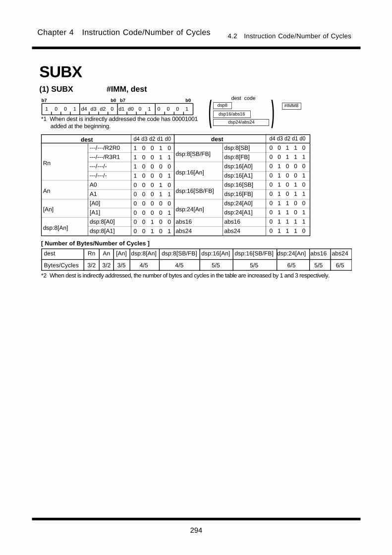
294
Chapter 4 Instruction Code/Number of Cycles 4.2 Instruction Code/Number of Cycles
SUBX(1) SUBX #IMM, destb7 b0 b7 b0
1 0 0 1 d4 d3 d2 0 d1 d0 0 1 0 0 0 1
dest Rn An [An] dsp:8[An] dsp:8[SB/FB] dsp:16[An] dsp:16[SB/FB] dsp:24[An] abs16 abs24
Bytes/Cycles 3/2 3/2 3/5 4/5 4/5 5/5 5/5 6/5 5/5 6/5
---/---/R2R0
---/---/R3R1
---/---/-
---/---/-
A0
A1
[A0]
[A1]
dsp:8[A0]
dsp:8[A1]
dsp:8[SB/FB]
dsp:16[An]
dsp:16[SB/FB]
dsp:24[An]
abs16
abs24
Rn
An
[An]
dsp:8[An]
destdest d4 d3 d2 d1 d0
1 0 0 1 0
1 0 0 1 1
1 0 0 0 0
1 0 0 0 1
0 0 0 1 0
0 0 0 1 1
0 0 0 0 0
0 0 0 0 1
0 0 1 0 0
0 0 1 0 1
d4 d3 d2 d1 d0
0 0 1 1 0
0 0 1 1 1
0 1 0 0 0
0 1 0 0 1
0 1 0 1 0
0 1 0 1 1
0 1 1 0 0
0 1 1 0 1
0 1 1 1 1
0 1 1 1 0
dsp24/abs24
dsp8
dsp16/abs16 )(dsp:8[SB]
dsp:8[FB]
dsp:16[A0]
dsp:16[A1]
dsp:16[SB]
dsp:16[FB]
dsp:24[A0]
dsp:24[A1]
abs16
abs24
#IMM8
dest code
*1 When dest is indirectly addressed the code has 00001001added at the beginning.
[ Number of Bytes/Number of Cycles ]
*2 When dest is indirectly addressed, the number of bytes and cycles in the table are increased by 1 and 3 respectively.
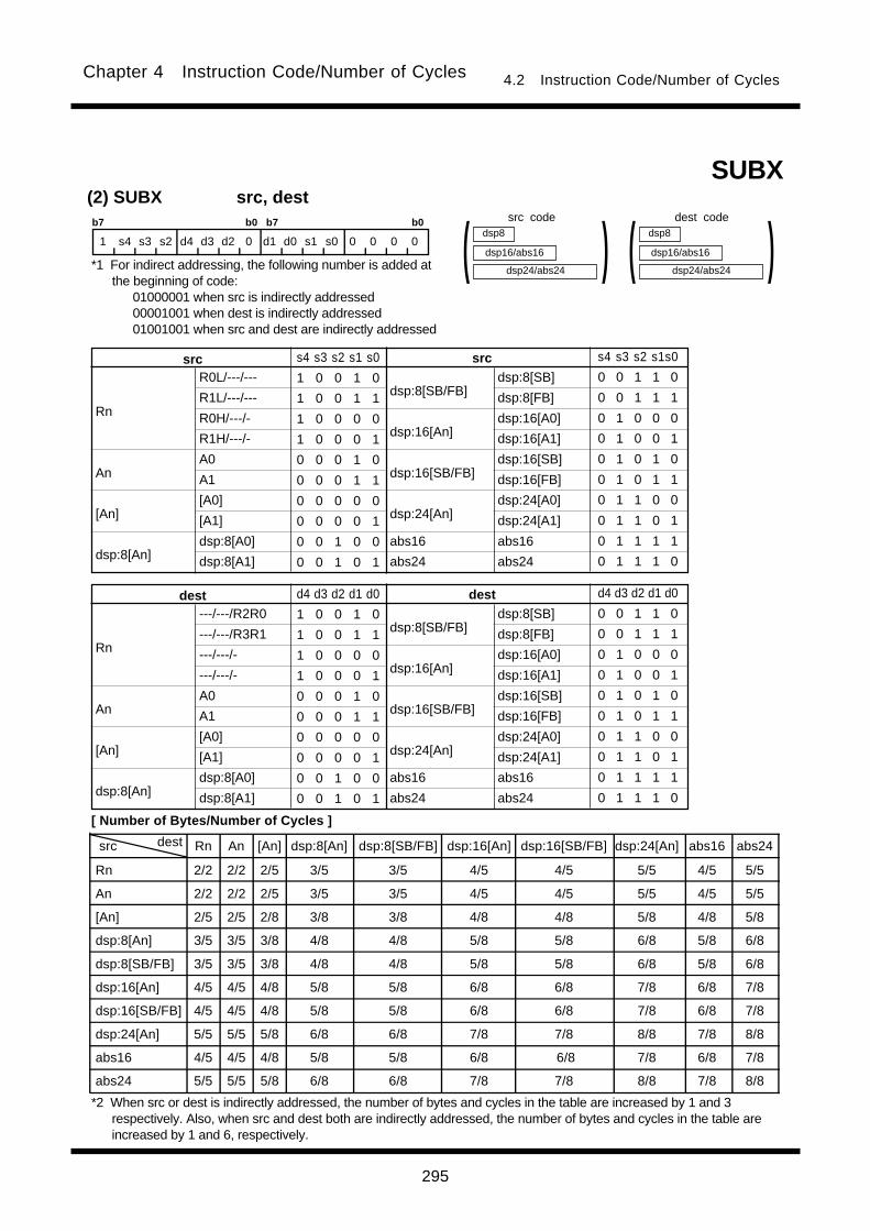
295
Chapter 4 Instruction Code/Number of Cycles 4.2 Instruction Code/Number of Cycles
src dest Rn An [An] dsp:8[An] dsp:8[SB/FB] dsp:16[An] dsp:16[SB/FB] dsp:24[An] abs16 abs24
Rn 2/2 2/2 2/5 3/5 3/5 4/5 4/5 5/5 4/5 5/5
An 2/2 2/2 2/5 3/5 3/5 4/5 4/5 5/5 4/5 5/5
[An] 2/5 2/5 2/8 3/8 3/8 4/8 4/8 5/8 4/8 5/8
dsp:8[An] 3/5 3/5 3/8 4/8 4/8 5/8 5/8 6/8 5/8 6/8
dsp:8[SB/FB] 3/5 3/5 3/8 4/8 4/8 5/8 5/8 6/8 5/8 6/8
dsp:16[An] 4/5 4/5 4/8 5/8 5/8 6/8 6/8 7/8 6/8 7/8
dsp:16[SB/FB] 4/5 4/5 4/8 5/8 5/8 6/8 6/8 7/8 6/8 7/8
dsp:24[An] 5/5 5/5 5/8 6/8 6/8 7/8 7/8 8/8 7/8 8/8
abs16 4/5 4/5 4/8 5/8 5/8 6/8 6/8 7/8 6/8 7/8
abs24 5/5 5/5 5/8 6/8 6/8 7/8 7/8 8/8 7/8 8/8
(2) SUBX src, destb7 b0 b7 b0
1 s4 s3 s2 d4 d3 d2 0 d1 d0 s1 s0 0 0 0 0
dsp24/abs24
dsp8
dsp16/abs16 )( dsp24/abs24
dsp8
dsp16/abs16 )(SUBX
R0L/---/---
R1L/---/---
R0H/---/-
R1H/---/-
A0
A1
[A0]
[A1]
dsp:8[A0]
dsp:8[A1]
dsp:8[SB/FB]
dsp:16[An]
dsp:16[SB/FB]
dsp:24[An]
abs16
abs24
Rn
An
[An]
dsp:8[An]
srcsrc s4 s3 s2 s1 s0
1 0 0 1 0
1 0 0 1 1
1 0 0 0 0
1 0 0 0 1
0 0 0 1 0
0 0 0 1 1
0 0 0 0 0
0 0 0 0 1
0 0 1 0 0
0 0 1 0 1
s4 s3 s2 s1s0
0 0 1 1 0
0 0 1 1 1
0 1 0 0 0
0 1 0 0 1
0 1 0 1 0
0 1 0 1 1
0 1 1 0 0
0 1 1 0 1
0 1 1 1 1
0 1 1 1 0
dsp:8[SB]
dsp:8[FB]
dsp:16[A0]
dsp:16[A1]
dsp:16[SB]
dsp:16[FB]
dsp:24[A0]
dsp:24[A1]
abs16
abs24
---/---/R2R0
---/---/R3R1
---/---/-
---/---/-
A0
A1
[A0]
[A1]
dsp:8[A0]
dsp:8[A1]
dsp:8[SB/FB]
dsp:16[An]
dsp:16[SB/FB]
dsp:24[An]
abs16
abs24
Rn
An
[An]
dsp:8[An]
destdest d4 d3 d2 d1 d0
1 0 0 1 0
1 0 0 1 1
1 0 0 0 0
1 0 0 0 1
0 0 0 1 0
0 0 0 1 1
0 0 0 0 0
0 0 0 0 1
0 0 1 0 0
0 0 1 0 1
d4 d3 d2 d1 d0
0 0 1 1 0
0 0 1 1 1
0 1 0 0 0
0 1 0 0 1
0 1 0 1 0
0 1 0 1 1
0 1 1 0 0
0 1 1 0 1
0 1 1 1 1
0 1 1 1 0
dsp:8[SB]
dsp:8[FB]
dsp:16[A0]
dsp:16[A1]
dsp:16[SB]
dsp:16[FB]
dsp:24[A0]
dsp:24[A1]
abs16
abs24
src code dest code
*1 For indirect addressing, the following number is added atthe beginning of code:
01000001 when src is indirectly addressed00001001 when dest is indirectly addressed01001001 when src and dest are indirectly addressed
[ Number of Bytes/Number of Cycles ]
*2 When src or dest is indirectly addressed, the number of bytes and cycles in the table are increased by 1 and 3respectively. Also, when src and dest both are indirectly addressed, the number of bytes and cycles in the table areincreased by 1 and 6, respectively.
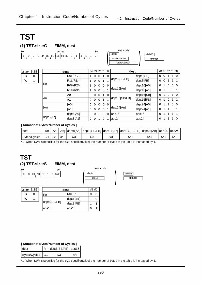
296
Chapter 4 Instruction Code/Number of Cycles 4.2 Instruction Code/Number of Cycles
dest Rn dsp:8[SB/FB] abs16
Bytes/Cycles 2/1 3/3 4/3
(2) TST.size:S #IMM, dest
.size
.B
.W
SIZE
0
1
b7 b0
0 0 d1 d0 1 1 0 SIZE
R0L/R0
dsp:8[SB]
dsp:8[FB]
abs16
Rn
dsp:8[SB/FB]
abs16
dest d1 d0
0 0
1 0
1 1
0 1
#IMM8
#IMM16
dsp8
abs16 )(TST
TST(1) TST.size:G #IMM, dest
.size
.B
.W
SIZE
0
1
b7 b0 b7 b0
1 0 0 1 d4 d3 d2 SIZE d1 d0 1 1 1 1 1 0
dest Rn An [An] dsp:8[An] dsp:8[SB/FB] dsp:16[An] dsp:16[SB/FB] dsp:24[An] abs16 abs24
Bytes/Cycles 3/1 3/1 3/3 4/3 4/3 5/3 5/3 6/3 5/3 6/3
R0L/R0/---
R1L/R1/---
R0H/R2/-
R1H/R3/-
A0
A1
[A0]
[A1]
dsp:8[A0]
dsp:8[A1]
dsp:8[SB/FB]
dsp:16[An]
dsp:16[SB/FB]
dsp:24[An]
abs16
abs24
Rn
An
[An]
dsp:8[An]
destdest d4 d3 d2 d1 d0
1 0 0 1 0
1 0 0 1 1
1 0 0 0 0
1 0 0 0 1
0 0 0 1 0
0 0 0 1 1
0 0 0 0 0
0 0 0 0 1
0 0 1 0 0
0 0 1 0 1
d4 d3 d2 d1 d0
0 0 1 1 0
0 0 1 1 1
0 1 0 0 0
0 1 0 0 1
0 1 0 1 0
0 1 0 1 1
0 1 1 0 0
0 1 1 0 1
0 1 1 1 1
0 1 1 1 0
dsp24/abs24
dsp8
dsp16/abs16 )(dsp:8[SB]
dsp:8[FB]
dsp:16[A0]
dsp:16[A1]
dsp:16[SB]
dsp:16[FB]
dsp:24[A0]
dsp:24[A1]
abs16
abs24
#IMM8
#IMM16
dest code
[ Number of Bytes/Number of Cycles ]
*1 When (.W) is specified for the size specifier(.size) the number of bytes in the table is increased by 1.
dest code
[ Number of Bytes/Number of Cycles ]
*1 When (.W) is specified for the size specifier(.size) the number of bytes in the table is increased by 1.
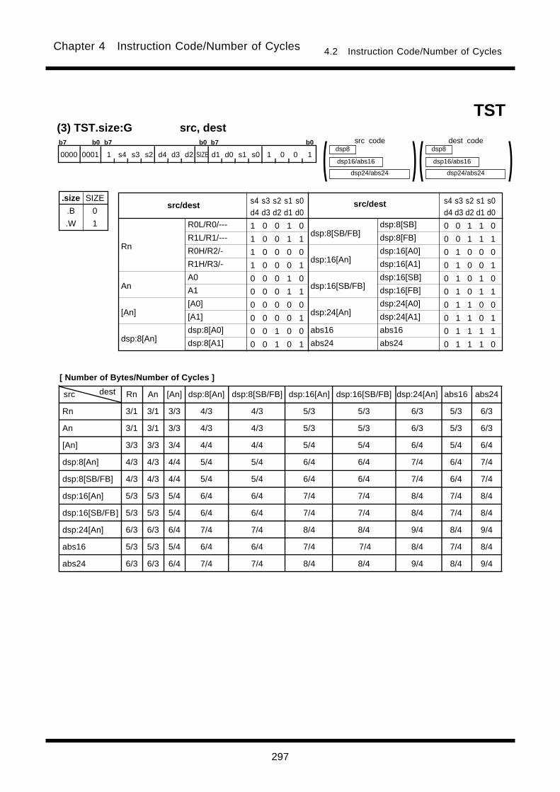
297
Chapter 4 Instruction Code/Number of Cycles 4.2 Instruction Code/Number of Cycles
src dest Rn An [An] dsp:8[An] dsp:8[SB/FB] dsp:16[An] dsp:16[SB/FB] dsp:24[An] abs16 abs24
Rn 3/1 3/1 3/3 4/3 4/3 5/3 5/3 6/3 5/3 6/3
An 3/1 3/1 3/3 4/3 4/3 5/3 5/3 6/3 5/3 6/3
[An] 3/3 3/3 3/4 4/4 4/4 5/4 5/4 6/4 5/4 6/4
dsp:8[An] 4/3 4/3 4/4 5/4 5/4 6/4 6/4 7/4 6/4 7/4
dsp:8[SB/FB] 4/3 4/3 4/4 5/4 5/4 6/4 6/4 7/4 6/4 7/4
dsp:16[An] 5/3 5/3 5/4 6/4 6/4 7/4 7/4 8/4 7/4 8/4
dsp:16[SB/FB] 5/3 5/3 5/4 6/4 6/4 7/4 7/4 8/4 7/4 8/4
dsp:24[An] 6/3 6/3 6/4 7/4 7/4 8/4 8/4 9/4 8/4 9/4
abs16 5/3 5/3 5/4 6/4 6/4 7/4 7/4 8/4 7/4 8/4
abs24 6/3 6/3 6/4 7/4 7/4 8/4 8/4 9/4 8/4 9/4
(3) TST.size:G src, dest
.size
.B
.W
SIZE
0
1 R0L/R0/---
R1L/R1/---
R0H/R2/-
R1H/R3/-
A0
A1
[A0]
[A1]
dsp:8[A0]
dsp:8[A1]
dsp:8[SB/FB]
dsp:16[An]
dsp:16[SB/FB]
dsp:24[An]
abs16
abs24
Rn
An
[An]
dsp:8[An]
src/destsrc/dest s4 s3 s2 s1 s0d4 d3 d2 d1 d0
1 0 0 1 0
1 0 0 1 1
1 0 0 0 0
1 0 0 0 1
0 0 0 1 0
0 0 0 1 1
0 0 0 0 0
0 0 0 0 1
0 0 1 0 0
0 0 1 0 1
s4 s3 s2 s1 s0d4 d3 d2 d1 d0
0 0 1 1 0
0 0 1 1 1
0 1 0 0 0
0 1 0 0 1
0 1 0 1 0
0 1 0 1 1
0 1 1 0 0
0 1 1 0 1
0 1 1 1 1
0 1 1 1 0
dsp24/abs24
dsp8
dsp16/abs16 )(dsp:8[SB]
dsp:8[FB]
dsp:16[A0]
dsp:16[A1]
dsp:16[SB]
dsp:16[FB]
dsp:24[A0]
dsp:24[A1]
abs16
abs24
dsp24/abs24
dsp8
dsp16/abs16 )(TST
b7 b0 b7 b0 b7 b0
0000 0001 1 s4 s3 s2 d4 d3 d2 SIZE d1 d0 s1 s0 1 0 0 1
src code dest code
[ Number of Bytes/Number of Cycles ]
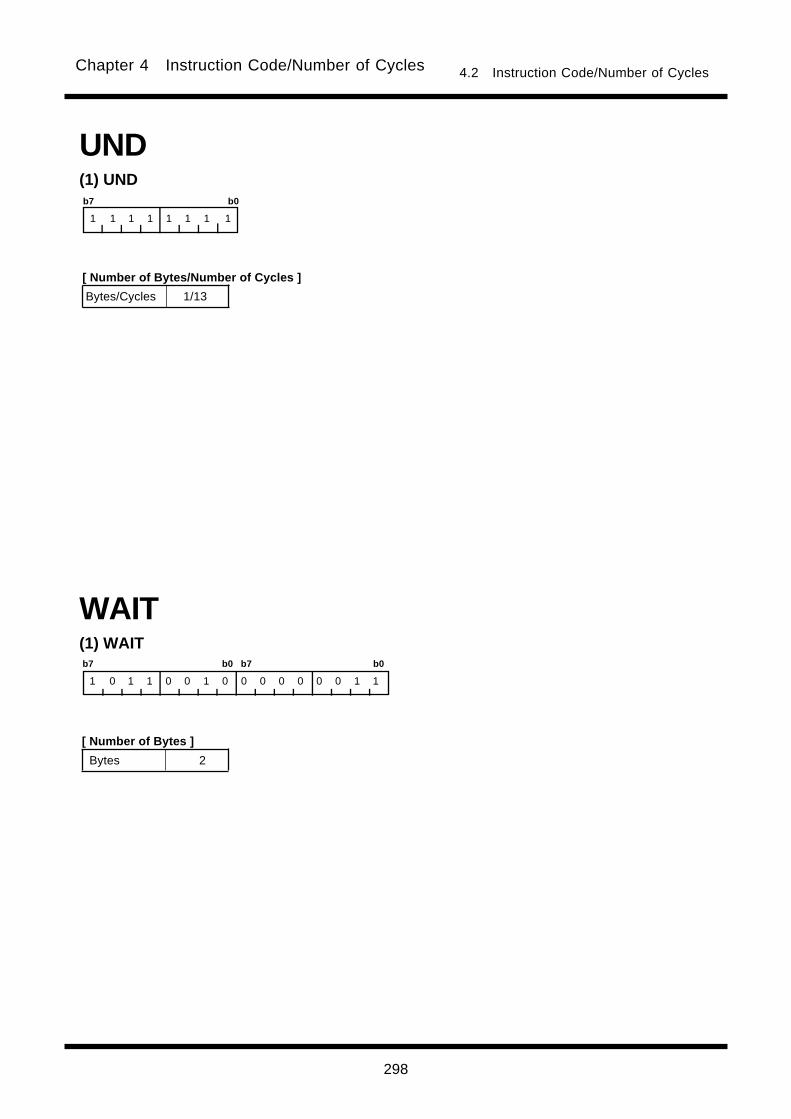
298
Chapter 4 Instruction Code/Number of Cycles 4.2 Instruction Code/Number of Cycles
UND(1) UNDb7 b0
1 1 1 1 1 1 1 1
(1) WAIT
WAIT
b7 b0 b7 b0
1 0 1 1 0 0 1 0 0 0 0 0 0 0 1 1
Bytes 2
Bytes/Cycles 1/13
[ Number of Bytes/Number of Cycles ]
[ Number of Bytes ]

299
Chapter 4 Instruction Code/Number of Cycles 4.2 Instruction Code/Number of Cycles
XOR(1) XOR.size #IMM, dest
.size
.B
.W
SIZE
0
1
b7 b0 b7 b0
1 0 0 1 d4 d3 d2 SIZE d1 d0 0 0 1 1 1 0
dest Rn An [An] dsp:8[An] dsp:8[SB/FB] dsp:16[An] dsp:16[SB/FB] dsp:24[An] abs16 abs24
Bytes/Cycles 3/1 3/1 3/3 4/3 4/3 5/3 5/3 6/3 5/3 6/3
R0L/R0/---
R1L/R1/---
R0H/R2/-
R1H/R3/-
A0
A1
[A0]
[A1]
dsp:8[A0]
dsp:8[A1]
dsp:8[SB/FB]
dsp:16[An]
dsp:16[SB/FB]
dsp:24[An]
abs16
abs24
Rn
An
[An]
dsp:8[An]
destdest d4 d3 d2 d1 d0
1 0 0 1 0
1 0 0 1 1
1 0 0 0 0
1 0 0 0 1
0 0 0 1 0
0 0 0 1 1
0 0 0 0 0
0 0 0 0 1
0 0 1 0 0
0 0 1 0 1
d4 d3 d2 d1 d0
0 0 1 1 0
0 0 1 1 1
0 1 0 0 0
0 1 0 0 1
0 1 0 1 0
0 1 0 1 1
0 1 1 0 0
0 1 1 0 1
0 1 1 1 1
0 1 1 1 0
dsp24/abs24
dsp8
dsp16/abs16 )(dsp:8[SB]
dsp:8[FB]
dsp:16[A0]
dsp:16[A1]
dsp:16[SB]
dsp:16[FB]
dsp:24[A0]
dsp:24[A1]
abs16
abs24
#IMM8
#IMM16
XCHG(1) XCHG.size src, dest
.size
.B
.W
SIZE
0
1
b7 b0 b7 b0
1 1 0 1 d4 d3 d2 SIZE d1 d0 0 0 1 SRC
dest Rn An [An] dsp:8[An] dsp:8[SB/FB] dsp:16[An] dsp:16[SB/FB] dsp:24[An] abs16 abs24
Bytes/cycles 2/3 2/3 2/4 3/4 3/4 4/4 4/4 5/4 4/4 5/4
R0L/R0/---
R1L/R1/---
R0H/R2/-
R1H/R3/-
A0
A1
[A0]
[A1]
dsp:8[A0]
dsp:8[A1]
dsp:8[SB/FB]
dsp:16[An]
dsp:16[SB/FB]
dsp:24[An]
abs16
abs24
Rn
An
[An]
dsp:8[An]
destdest d4 d3 d2 d1 d0
1 0 0 1 0
1 0 0 1 1
1 0 0 0 0
1 0 0 0 1
0 0 0 1 0
0 0 0 1 1
0 0 0 0 0
0 0 0 0 1
0 0 1 0 0
0 0 1 0 1
d4 d3 d2 d1 d0
0 0 1 1 0
0 0 1 1 1
0 1 0 0 0
0 1 0 0 1
0 1 0 1 0
0 1 0 1 1
0 1 1 0 0
0 1 1 0 1
0 1 1 1 1
0 1 1 1 0
dsp24/abs24
dsp8
dsp16/abs16 )(dsp:8[SB]
dsp:8[FB]
dsp:16[A0]
dsp:16[A1]
dsp:16[SB]
dsp:16[FB]
dsp:24[A0]
dsp:24[A1]
abs16
abs24
R0L/R0/---
R1L/R1/---
R0H/R2/-
R1H/R3/-
A0
A1
src SRC
0 0 0
0 0 1
1 0 0
1 0 1
0 1 0
0 1 1
*1 When dest is indirectly addressed the code has 00001001added at the beginning.
dest code
[ Number of Bytes/Number of Cycles ]
*2 When dest is indirectly addressed, the number of bytes and cycles in the table are increased by 1 and 3 respectively.
dest code
*1 When dest is indirectly addressed,the code has 00001001added at the beginning.
[ Number of Bytes/Number of Cycles ]
*2 When (.W) is specified for the size specifier(.size) the number of bytes in the table is increased by 1.
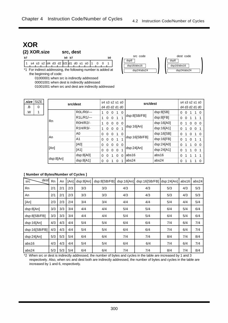
300
Chapter 4 Instruction Code/Number of Cycles 4.2 Instruction Code/Number of Cycles
src dest Rn An [An] dsp:8[An] dsp:8[SB/FB] dsp:16[An] dsp:16[SB/FB] dsp:24[An] abs16 abs24
Rn 2/1 2/1 2/3 3/3 3/3 4/3 4/3 5/3 4/3 5/3
An 2/1 2/1 2/3 3/3 3/3 4/3 4/3 5/3 4/3 5/3
[An] 2/3 2/3 2/4 3/4 3/4 4/4 4/4 5/4 4/4 5/4
dsp:8[An] 3/3 3/3 3/4 4/4 4/4 5/4 5/4 6/4 5/4 6/4
dsp:8[SB/FB] 3/3 3/3 3/4 4/4 4/4 5/4 5/4 6/4 5/4 6/4
dsp:16[An] 4/3 4/3 4/4 5/4 5/4 6/4 6/4 7/4 6/4 7/4
dsp:16[SB/FB] 4/3 4/3 4/4 5/4 5/4 6/4 6/4 7/4 6/4 7/4
dsp:24[An] 5/3 5/3 5/4 6/4 6/4 7/4 7/4 8/4 7/4 8/4
abs16 4/3 4/3 4/4 5/4 5/4 6/4 6/4 7/4 6/4 7/4
abs24 5/3 5/3 5/4 6/4 6/4 7/4 7/4 8/4 7/4 8/4
(2) XOR.size src, dest
.size
.B
.W
SIZE
0
1 R0L/R0/---
R1L/R1/---
R0H/R2/-
R1H/R3/-
A0
A1
[A0]
[A1]
dsp:8[A0]
dsp:8[A1]
dsp:8[SB/FB]
dsp:16[An]
dsp:16[SB/FB]
dsp:24[An]
abs16
abs24
Rn
An
[An]
dsp:8[An]
src/destsrc/dest s4 s3 s2 s1 s0d4 d3 d2 d1 d0
1 0 0 1 0
1 0 0 1 1
1 0 0 0 0
1 0 0 0 1
0 0 0 1 0
0 0 0 1 1
0 0 0 0 0
0 0 0 0 1
0 0 1 0 0
0 0 1 0 1
s4 s3 s2 s1 s0d4 d3 d2 d1 d0
0 0 1 1 0
0 0 1 1 1
0 1 0 0 0
0 1 0 0 1
0 1 0 1 0
0 1 0 1 1
0 1 1 0 0
0 1 1 0 1
0 1 1 1 1
0 1 1 1 0
dsp:8[SB]
dsp:8[FB]
dsp:16[A0]
dsp:16[A1]
dsp:16[SB]
dsp:16[FB]
dsp:24[A0]
dsp:24[A1]
abs16
abs24
XOR
b7 b0 b7 b0
1 s4 s3 s2 d4 d3 d2 SIZE d1 d0 s1 s0 1 0 0 1
dsp24/abs24
dsp8
dsp16/abs16 )( dsp24/abs24
dsp8
dsp16/abs16 )(src code dest code
*1 For indirect addressing, the following number is added atthe beginning of code:
01000001 when src is indirectly addressed00001001 when dest is indirectly addressed01001001 when src and dest are indirectly addressed
*2 When src or dest is indirectly addressed, the number of bytes and cycles in the table are increased by 1 and 3respectively. Also, when src and dest both are indirectly addressed, the number of bytes and cycles in the table areincreased by 1 and 6, respectively.
[ Number of Bytes/Number of Cycles ]

Chapter 5
Interrupt
5.1 Outline of Interrupt
5.2 Interrupt Control
5.3 Interrupt Sequence
5.4 Return from Interrupt Routine
5.5 Interrupt Priority
5.6 Multiple Interrupts
5.7 Precautions for Interrupts
5.8 Exit from Stop Mode and Wait Mode

302
Chapter 5 Interrupt
Undefined instruction (UND instruction)Overflow (INTO instruction)BRK instructionBRK2 instructionINT instruction
Remarks
Interrupt generated by the UND instruction.Interrupt generated by the INTO instruction.Executed beginning from address indicated byvector in variable vector table if content of addressFFFFE716 is FF16.Can be controlled by an interrupt enable bit.
_______
External interrupt generated by driving NMI pin low.
Software
Hardware
Interrupt
Reset_______
NMIWatchdog timerSingle stepAddress matched
*1 Peripheral I/O interrupts are generated by the peripheral functions built into the microcomputer
system. High-speed interrupt can be used as highest priority in peripheral I/O interrupts.
Special
Peripheral I/O*1
5.1 Outline of InterruptWhen an interrupt request is acknowledged, control branches to the interrupt routine that is set to an inter-
rupt vector table. Each interrupt vector table must have had the start address of its corresponding interrupt
routine set. For details about the interrupt vector table, refer to Section 1.10, “Vector Table.”
5.1.1 Types of InterruptsFigure 5.1.1 lists the types of interrupts. Table 5.1.1 and 5.1.2 list the source of interrupts (non-
maskable) and the fixed vector tables.
Vector table addressesAddress (L) to address (H)
5.1 Outline of Interrupt
Interrupt source
Watchdog timerAddress match
Undefined instructionOverflow
BRK instruction
_______
NMI
Reset
FFFFDC16 to FFFFDF16
FFFFE016 to FFFFE316
FFFFE416 to FFFFE716
FFFFE816 to FFFFEB16
FFFFF016 to FFFFF316
FFFFF816 to FFFFFB16
FFFFFC16 to FFFFFF16
Figure 5.1.1. Classification of interrupts
Table 5.1.1 Interrupt Source (Nonmaskable) and Fixed Vector Table
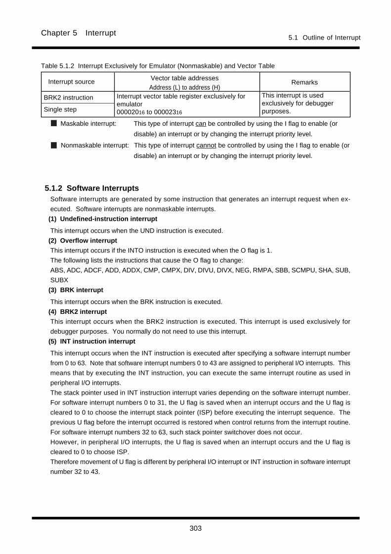
303
Chapter 5 Interrupt
5.1.2 Software InterruptsSoftware interrupts are generated by some instruction that generates an interrupt request when ex-
ecuted. Software interrupts are nonmaskable interrupts.
(1) Undefined-instruction interrupt
This interrupt occurs when the UND instruction is executed.
(2) Overflow interrupt
This interrupt occurs if the INTO instruction is executed when the O flag is 1.
The following lists the instructions that cause the O flag to change:
ABS, ADC, ADCF, ADD, ADDX, CMP, CMPX, DIV, DIVU, DIVX, NEG, RMPA, SBB, SCMPU, SHA, SUB,
SUBX
(3) BRK interrupt
This interrupt occurs when the BRK instruction is executed.
(4) BRK2 interrupt
This interrupt occurs when the BRK2 instruction is executed. This interrupt is used exclusively for
debugger purposes. You normally do not need to use this interrupt.
(5) INT instruction interrupt
This interrupt occurs when the INT instruction is executed after specifying a software interrupt number
from 0 to 63. Note that software interrupt numbers 0 to 43 are assigned to peripheral I/O interrupts. This
means that by executing the INT instruction, you can execute the same interrupt routine as used in
peripheral I/O interrupts.
The stack pointer used in INT instruction interrupt varies depending on the software interrupt number.
For software interrupt numbers 0 to 31, the U flag is saved when an interrupt occurs and the U flag is
cleared to 0 to choose the interrupt stack pointer (ISP) before executing the interrupt sequence. The
previous U flag before the interrupt occurred is restored when control returns from the interrupt routine.
For software interrupt numbers 32 to 63, such stack pointer switchover does not occur.
However, in peripheral I/O interrupts, the U flag is saved when an interrupt occurs and the U flag is
cleared to 0 to choose ISP.
Therefore movement of U flag is different by peripheral I/O interrupt or INT instruction in software interrupt
number 32 to 43.
5.1 Outline of Interrupt
Remarks
This interrupt is usedexclusively for debuggerpurposes.
Vector table addressesAddress (L) to address (H)
Interrupt source
BRK2 instruction
Single step
Interrupt vector table register exclusively foremulator00002016 to 00002316
Table 5.1.2 Interrupt Exclusively for Emulator (Nonmaskable) and Vector Table
Maskable interrupt: This type of interrupt can be controlled by using the I flag to enable (or
disable) an interrupt or by changing the interrupt priority level.
Nonmaskable interrupt: This type of interrupt cannot be controlled by using the I flag to enable (or
disable) an interrupt or by changing the interrupt priority level.

304
Chapter 5 Interrupt
5.1.3 Hardware InterruptsThere are Two types in hardware Interrupts; special interrupts and Peripheral I/O interrupts.
(1) Special interrupts
Special interrupts are nonmaskable interrupts.
• Reset____________
A reset occurs when the RESET pin is pulled low.______
• NMI interrupt______
This interrupt occurs when the NMI pin is pulled low.
• Watchdog timer interrupt
This interrupt is caused by the watchdog timer.
• Address-match interrupt
This interrupt occurs when the program's execution address matches the content of the address match
register while the address match interrupt enable bit is set (= 1).
This interrupt does not occur if any address other than the start address of an instruction is set in the
address match register.
• Single-step interrupt
This interrupt is used exclusively for debugger purposes. You normally do not need to use this inter-
rupt. A single-step interrupt occurs when the D flag is set (= 1); in this case, an interrupt is generated
each time an instruction is executed.
(2) Peripheral I/O interrupts
These interrupts are generated by the peripheral functions built into the microcomputer system. The
types of built-in peripheral functions vary with each M16C model, so do the types of interrupt causes. The
interrupt vector table uses the same software interrupt numbers 0–43 that are used by the INT instruction.
Peripheral I/O interrupts are maskable interrupts. For details about peripheral I/O interrupts, refer to the
M16C User’s Manual.
For peripheral I/O interrupts, the U flag is saved when an interrupt occurs and the U flag is cleared to 0 to
choose the interrupt stack pointer (ISP) before executing the interrupt sequence. The previous U flag
before the interrupt occurred is restored when control returns from the interrupt routine.
(3) High-speed interrupts
High-speed interrupts are interrupts in which the response is executed at high-speed. High-speed inter-
rupt can be used as highest priority in peripheral I/O interrupts.
Execute a FREIT instruction to return from the high-speed interrupt routine.
For details about high-speed interrupt, refer to the M16C User’s Manual.
5.1 Outline of Interrupt

305
Chapter 5 Interrupt
FSET I
Time
5.2 Interrupt ControlThe following explains how to enable/disable maskable interrupts and set acknowledge priority. The expla-
nation here does not apply to non-maskable interrupts.
Maskable interrupts are enabled and disabled by using the interrupt enable flag (I flag), interrupt priority
level select bit, and processor interrupt priority level (IPL). Whether there is any interrupt requested is
indicated by the interrupt request bit. The interrupt request bit and interrupt priority level select bit are
arranged in the interrupt control register provided for each specific interrupt. The interrupt enable flag (I
flag) and processor interrupt priority level (IPL) are arranged in the flag register (FLG).
For details about the memory allocation and the configuration of interrupt control registers, refer to the
M16C User's Manual.
5.2.1 Interrupt Enable Flag (I Flag)The interrupt enable flag (I flag) is used to disable/enable maskable interrupts. When this flag is set (=
1), all maskable interrupts are enabled; when the flag is cleared to 0, they are disabled. This flag is
automatically cleared to 0 after a reset is cleared.
When the I flag is changed, the altered flag status is reflected in determining whether or not to accept an
interrupt request at the following timing:
• If the flag is changed by an REIT or FREIT instruction, the changed status takes effect begin-
ning with that REIT or FREIT instruction.
• If the flag is changed by an FCLR, FSET, POPC, or LDC instruction, the changed status takes
effect beginning with the next instruction.
Previousinstruction
Interrupt sequenceREIT
Interrupt sequence Next instructionPreviousinstruction
Time
Figure 5.2.1 Timing at which changes of I flag are reflected in interrupt handling
Interrupt request generated
Interrupt request generated
5.2 Interrupt Control
When changed by REIT or FREIT instruction
Determination whether or not toaccept interrupt request
Determination whether or not toaccept interrupt request
When changed by FCLR, FSET, POPC, or LDC instruction
(If I flag is changed from 0 to 1 by REIT instruction)
(If I flag is changed from 0 to 1 by FSET instruction)
5.2.2 Interrupt Request BitThis bit is set (= 1) when an interrupt request is generated. This bit remains set until the interrupt request
is acknowledged. The bit is cleared to 0 when the interrupt request is acknowledged.
This bit can be cleared to 0 (but cannot be set to 1) in software.
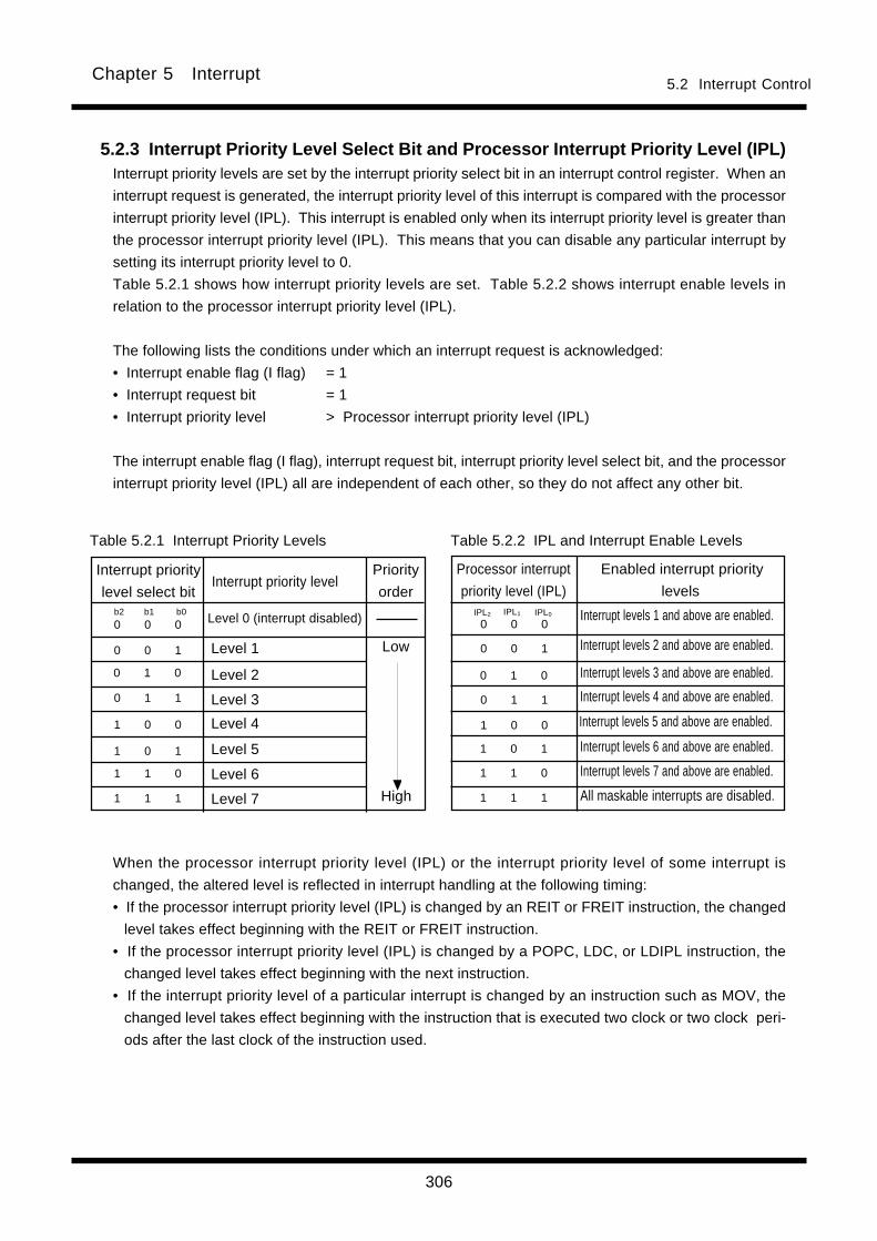
306
Chapter 5 Interrupt
When the processor interrupt priority level (IPL) or the interrupt priority level of some interrupt is
changed, the altered level is reflected in interrupt handling at the following timing:
• If the processor interrupt priority level (IPL) is changed by an REIT or FREIT instruction, the changed
level takes effect beginning with the REIT or FREIT instruction.
• If the processor interrupt priority level (IPL) is changed by a POPC, LDC, or LDIPL instruction, the
changed level takes effect beginning with the next instruction.
• If the interrupt priority level of a particular interrupt is changed by an instruction such as MOV, the
changed level takes effect beginning with the instruction that is executed two clock or two clock peri-
ods after the last clock of the instruction used.
5.2.3 Interrupt Priority Level Select Bit and Processor Interrupt Priority Level (IPL)Interrupt priority levels are set by the interrupt priority select bit in an interrupt control register. When an
interrupt request is generated, the interrupt priority level of this interrupt is compared with the processor
interrupt priority level (IPL). This interrupt is enabled only when its interrupt priority level is greater than
the processor interrupt priority level (IPL). This means that you can disable any particular interrupt by
setting its interrupt priority level to 0.
Table 5.2.1 shows how interrupt priority levels are set. Table 5.2.2 shows interrupt enable levels in
relation to the processor interrupt priority level (IPL).
The following lists the conditions under which an interrupt request is acknowledged:
• Interrupt enable flag (I flag) = 1
• Interrupt request bit = 1
• Interrupt priority level > Processor interrupt priority level (IPL)
The interrupt enable flag (I flag), interrupt request bit, interrupt priority level select bit, and the processor
interrupt priority level (IPL) all are independent of each other, so they do not affect any other bit.
0 1 0
0 1 1
1 1 0
1 1 1
0 0 1
0 0 0
Low
High
1 0 1
1 1 0
1 1 1
0 0 0
1 0 0
0 0 1
0 1 0
0 1 1
Table 5.2.2 IPL and Interrupt Enable LevelsTable 5.2.1 Interrupt Priority Levels
Interrupt priority
level select bitInterrupt priority level
Priority
orderb0b1b2
1 0 0
1 0 1
Processor interrupt
priority level (IPL)
Enabled interrupt priority
levelsIPL1 IPL0 Interrupt levels 1 and above are enabled.
Interrupt levels 2 and above are enabled.
Interrupt levels 3 and above are enabled.
Interrupt levels 4 and above are enabled.
Interrupt levels 5 and above are enabled.
Interrupt levels 6 and above are enabled.
Interrupt levels 7 and above are enabled.
All maskable interrupts are disabled.
Level 0 (interrupt disabled)
Level 1
Level 2
Level 3
Level 4
Level 5
Level 6
Level 7
IPL2
5.2 Interrupt Control

307
Chapter 5 Interrupt5.2 Interrupt Control
5.2.4 Rewrite the interrupt control registerWhen a instruction to rewrite the interrupt control register is executed but the interrupt is disabled, the
interrupt request bit is not set sometimes even if the interrupt request for that register has been gener-
ated. This will depend on the instruction. If this creates problems, use the below instructions to change
the register.
Instructions : AND, OR, BCLR, BSET
5.3 Interrupt SequenceAn interrupt sequence — what are performed over a period from the instant an interrupt is accepted to the
instant the interrupt routine is executed — is described here.
If an interrupt occurs during execution of an instruction, the processor determines its priority when the
execution of the instruction is completed, and transfers control to the interrupt sequence from the next
cycle. If an interrupt occurs during execution of either the SCMPU, SIN, SMOVB, SMOVF, SMOVU,
SSTR, SOUT or RMPA instruction, the processor temporarily suspends the instruction being executed,
and transfers control to the interrupt sequence.
In the interrupt sequence, the processor carries out the following in sequence given:
(1) CPU gets the interrupt information (the interrupt number and interrupt request level) by reading address
00000016 (address 00000216 when high-speed interrupt).
(2) Saves the content of the flag register (FLG) as it was immediately before the start of interrupt sequence
in the temporary register (Note) within the CPU.
(3) Sets the interrupt enable flag (I flag), the debug flag (D flag), and the stack pointer select flag (U flag) to
“0” (the U flag, however does not change if the INT instruction, in software interrupt numbers 32 through
63, is executed)
(4) Saves the content of the temporary register (Note 1) within the CPU in the stack area. Saves in the flag
save register (SVF) in high-speed interrupt.
(5) Saves the content of the program counter (PC) in the stack area. Saves in the PC save register (SVP)
in high-speed interrupt.
(6) Sets the interrupt priority level of the accepted instruction in the IPL.
After the interrupt sequence is completed, the processor resumes executing instructions from the first ad-
dress of the interrupt routine.
Note: This register cannot be utilized by the user.
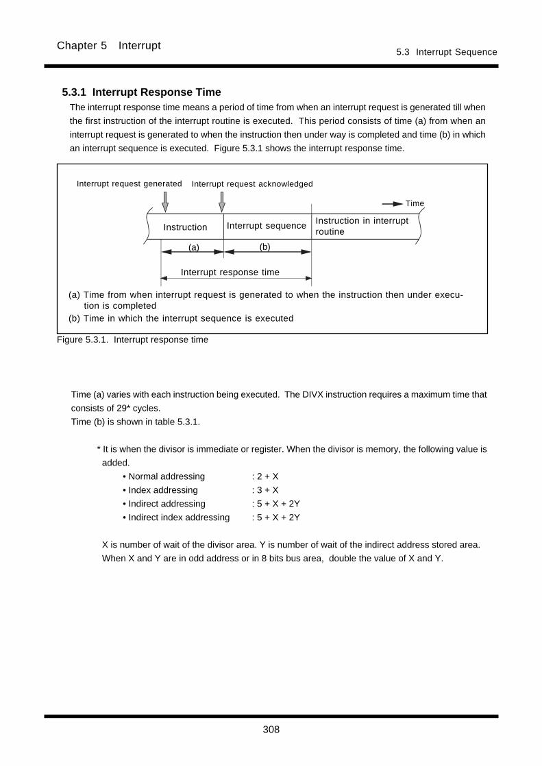
308
Chapter 5 Interrupt
Time (a) varies with each instruction being executed. The DIVX instruction requires a maximum time that
consists of 29* cycles.
Time (b) is shown in table 5.3.1.
* It is when the divisor is immediate or register. When the divisor is memory, the following value is
added.
• Normal addressing : 2 + X
• Index addressing : 3 + X
• Indirect addressing : 5 + X + 2Y
• Indirect index addressing : 5 + X + 2Y
X is number of wait of the divisor area. Y is number of wait of the indirect address stored area.
When X and Y are in odd address or in 8 bits bus area, double the value of X and Y.
5.3.1 Interrupt Response TimeThe interrupt response time means a period of time from when an interrupt request is generated till when
the first instruction of the interrupt routine is executed. This period consists of time (a) from when an
interrupt request is generated to when the instruction then under way is completed and time (b) in which
an interrupt sequence is executed. Figure 5.3.1 shows the interrupt response time.
Figure 5.3.1. Interrupt response time
(a) (b)
Time
Instruction
Interrupt response time
Instruction in interruptroutine
Interrupt sequence
Interrupt request acknowledgedInterrupt request generated
(a) Time from when interrupt request is generated to when the instruction then under execu-tion is completed
(b) Time in which the interrupt sequence is executed
5.3 Interrupt Sequence

309
Chapter 5 Interrupt
Table 5.3.1 Interrupt Sequence Execution Time
8 bits data bus
16 cycles
16 cycles
14 cycles
14 cycles
15 cycles
16 cycles
19 cycles
19 cycles
21 cycles
16 bits data bus
14 cycles
16 cycles
12 cycles
14 cycles
13 cycles
14 cycles
17 cycles
19 cycles
19 cycles
Interrupt vector address
Even address
Odd address*2
Even address
Odd address*2
Even address*1
Even address*1
Even address
Odd address*2
Even address*1
Vector table is internal register
5.3 Interrupt Sequence
*1 The vector table is fixed to even address.*2 Allocate interrupt vector addresses in even addresses as must as possible.*3 The high-speed interrupt is independent of these conditions.
Interrupt
Peripheral I/O
INT instruction
_______
NMI
Watchdog timer
Undefined instruction
Address match
Overflow
BRK instruction
(Variable vector table)
Single step
BRK2 instruction
BRK instruction
(Fixed vector table)
High-speed interrupt*3 5 cycles
Value that is set to IPL
7
0
Not changed
5.3.2 Changes of IPL When Interrupt Request AcknowledgedWhen an interrupt request is acknowledged, the interrupt priority level of the acknowledged interrupt is
set to the processor interrupt priority level (IPL).
If an interrupt request is acknowledged that does not have an interrupt priority level, the value shown in
Table 5.3.2 is set to the IPL.
Table 5.3.2 Relationship between Interrupts without Interrupt Priority Levels and IPL
Interrupt sources without interrupt priority levels_______
Watchdog timer, NMI
Reset
Other

310
Chapter 5 Interrupt
5.3.3 Saving RegistersIn an interrupt sequence, only the contents of the flag register (FLG) and program counter (PC) are
saved to the stack area.
The order in which these contents are saved is as follows: First, the FLG register is saved to the stack
area. Next, the 16 high-order bits and 16 low-order bits of the program counter expanded to 32-bit are
saved. Figure 5.3.2 shows the stack status before an interrupt request is acknowledged and the stack
status after an interrupt request is acknowledged.
In a high-speed interrupt sequence, the contents of the flag register (FLG) is saved to the flag save
register (SVF) and program counter (PC) is saved to PC save register (SVP).
If there are any other registers you want to be saved, save them in software at the beginning of the
interrupt routine. The PUSHM instruction allows you to save all registers except the stack pointer (SP)
by a single instruction.
5.3 Interrupt Sequence
[SP]Stack pointervalue beforeinterrupt occurs
Stack status before interrupt request is acknowledged
Address
Stack status after interrupt request is acknowledged
Figure 5.3.2 Stack status before and after an interrupt request is acknowledged
m-6
m-5
m–4
m–3
m–2
m–1
m
m+1
LSBMSBLSBMSBAddress Stack area Stack area
Flag register(FLGL)
Program counter(PCH)
Flag register(FLGH)
Content ofprevious stack
Content ofprevious stack
Content ofprevious stackContent ofprevious stack
Program counter(PCL)
Program counter(PCM)
[SP]New stackpointer value
m-6
m-5
m–4
m–3
m–2
m–1
m
m+1
0 0

311
Chapter 5 Interrupt
5.5 Interrupt PriorityIf two or more interrupt requests are sampled active at the same time, whichever interrupt request is ac-
knowledged that has the highest priority.
Maskable interrupts (Peripheral I/O interrupts) can be assigned any desired priority by setting the interrupt
priority level select bit accordingly. If some maskable interrupts are assigned the same priority level, the
interrupt that a request came to most in the first place is accepted at first, and then, the priority between
these interrupts is resolved by the priority that is set in hardware*1.
Certain nonmaskable interrupts such as a reset (reset is given the highest priority) and watchdog timer
interrupt have their priority levels set in hardware. Figure 5.5.1 lists the hardware priority levels of these
interrupts.
Software interrupts are not subjected to interrupt priority. They always cause control to branch to an inter-
rupt routine whenever the relevant instruction is executed.
*1 Hardware priority varies with each M16C model. Please refer to your M16C User’s Manual.
_______
Reset > NMI > Watchdog > Peripheral I/O > Single step > Address match
Figure 5.5.1. Interrupt priority that is set in hardware
5.4 Return from Interrupt RoutineAs you execute the REIT instruction at the end of the interrupt routine, the contents of the flag register (FLG)
and program counter (PC) that have been saved to the stack area immediately preceding the interrupt
sequence are automatically restored. In high-speed interrupt, as you execute the REIT instruction at the end
of the interrupt routine, the contents of the flag register (FLG) and program counter (PC) that have been
saved to the save registers immediately preceding the interrupt sequence are automatically restored.
Then control returns to the routine that was under execution before the interrupt request was acknowledged,
and processing is resumed from where control left off.
If there are any registers you saved via software in the interrupt routine, be sure to restore them using an
instruction (e.g., POPM instruction) before executing the REIT or FREIT instruction.
5.4 Return from Interrupt Routine

312
Chapter 5 Interrupt
5.6 Multiple InterruptsThe following shows the internal bit states when control has branched to an interrupt routine:
• The interrupt enable flag (I flag) is cleared to 0 (interrupts disabled).
• The interrupt request bit for the acknowledged interrupt is cleared to 0.
• The processor interrupt priority level (IPL) equals the interrupt priority level of the acknowledged interrupt.
By setting the interrupt enable flag (I flag) (= 1) in the interrupt routine, you can reenable interrupts so that an
interrupt request can be acknowledged that has higher priority than the processor interrupt priority level
(IPL). Figure 5.6.1 shows how multiple interrupts are handled.
The interrupt requests that have not been acknowledged for their low interrupt priority level are kept pend-
ing. When the IPL is restored by an REIT and FREIT instruction and interrupt priority is resolved against it,
the pending interrupt request is acknowledged if the following condition is met:
Interrupt priority level of
pending interrupt request
Restored processor interrupt
priority level (IPL)>
5.6 Multiple interrupts

313
Chapter 5 Interrupt
I = 0
IPL = 0
I = 1
I = 0
IPL = 3
I = 1
I = 0
IPL = 5
REIT
I = 1
IPL = 3
REIT
I = 1
IPL = 0
I = 0
IPL = 2
REIT
I = 1
IPL = 0
Interrupt priority level = 3
Interrupt priority level = 5
Interrupt 3
Interrupt priority level = 2
Not acknowledged because
of low interrupt priority
Main routine instructions
are not executed.
Interrupt requestgenerated Nesting
Main routineResetTime
Interrupt 1
Interrupt 1
Interrupt 2
Figure 5.6.1. Multiple interrupts
: Automatically executed.: Be sure to set in software.
I : Interrupt enable flagIPL : Processor interrupt priority level
REIT
Interrupt 3
Interrupt 3
REIT
Interrupt 2
Multiple interrupts
5.6 Multiple interrupts
REIT

314
Chapter 5 Interrupt
5.7 Precautions for Interrupts(1) Reading addresses 000000 16 and 00000216
• When maskable interrupt is occurred, CPU read the interrupt information (the interrupt number and
interrupt request level) in the interrupt sequence from address 00000016. When high-speed interrupt
is occurred, CPU read from address 00000216.
The interrupt request bit of the certain interrupt will then be set to “0”.
However, reading addresses 00000016 and 00000216 by software does not set request bit to “0”.
(2) Setting the stack pointer• The value of the stack pointer immediately after reset is initialized to 00000016. Accepting an interrupt
before setting a value in the stack pointer may become a factor of runaway. Be sure to set a value in_______
the stack pointer before accepting an interrupt. When using the NMI interrupt, initialize the stack_______
pointer at the beginning of a program. Any interrupt including the NMI interrupt is generated immedi-
ately after executing the first instruction after reset. Set an even number to the stack pointer. When an
even number is set, execution efficiency is increased.
(3) Rewrite the interrupt control register
• When a instruction to rewrite the interrupt control register is executed but the interrupt is disabled, the
interrupt request bit is not set sometimes even if the interrupt request for that register has been gener-
ated. This will depend on the instruction. If this creates problems, use the below instructions to change
the register.
Instructions : AND, OR, BCLR, BSET
5.8 Exit from Stop Mode and Wait ModeWhen using an peripheral I/O interrupt to exit stop mode or wait mode, the relevant interrupt must have been
enabled and set to a priority level above the level set by the interrupt priority set bits for exiting a stop/wait
state. Set the interrupt priority set bits for exiting a stop/wait state to the same level as the processor interrupt
level (IPL) of flag register (FLG)._______
RESET and NMI interrupt are independent of the interrupt priority set bits for exiting a stop/wait state, and
stop/wait state is exited.

Chapter 6
Calculation Number of Cycles
6.1 Instruction queue buffer
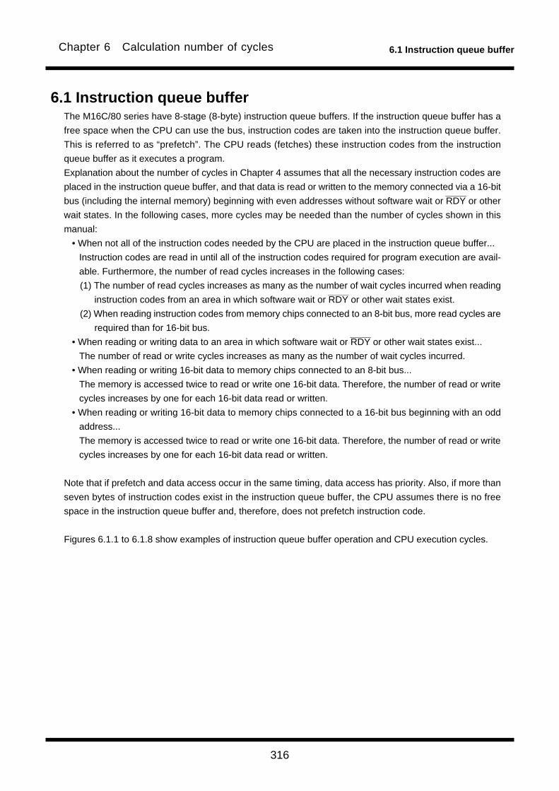
316
6.1 Instruction queue bufferChapter 6 Calculation number of cycles
6.1 Instruction queue bufferThe M16C/80 series have 8-stage (8-byte) instruction queue buffers. If the instruction queue buffer has a
free space when the CPU can use the bus, instruction codes are taken into the instruction queue buffer.
This is referred to as “prefetch”. The CPU reads (fetches) these instruction codes from the instruction
queue buffer as it executes a program.
Explanation about the number of cycles in Chapter 4 assumes that all the necessary instruction codes are
placed in the instruction queue buffer, and that data is read or written to the memory connected via a 16-bit________
bus (including the internal memory) beginning with even addresses without software wait or RDY or other
wait states. In the following cases, more cycles may be needed than the number of cycles shown in this
manual:
• When not all of the instruction codes needed by the CPU are placed in the instruction queue buffer...
Instruction codes are read in until all of the instruction codes required for program execution are avail-
able. Furthermore, the number of read cycles increases in the following cases:
(1) The number of read cycles increases as many as the number of wait cycles incurred when reading________
instruction codes from an area in which software wait or RDY or other wait states exist.
(2) When reading instruction codes from memory chips connected to an 8-bit bus, more read cycles are
required than for 16-bit bus.________
• When reading or writing data to an area in which software wait or RDY or other wait states exist...
The number of read or write cycles increases as many as the number of wait cycles incurred.
• When reading or writing 16-bit data to memory chips connected to an 8-bit bus...
The memory is accessed twice to read or write one 16-bit data. Therefore, the number of read or write
cycles increases by one for each 16-bit data read or written.
• When reading or writing 16-bit data to memory chips connected to a 16-bit bus beginning with an odd
address...
The memory is accessed twice to read or write one 16-bit data. Therefore, the number of read or write
cycles increases by one for each 16-bit data read or written.
Note that if prefetch and data access occur in the same timing, data access has priority. Also, if more than
seven bytes of instruction codes exist in the instruction queue buffer, the CPU assumes there is no free
space in the instruction queue buffer and, therefore, does not prefetch instruction code.
Figures 6.1.1 to 6.1.8 show examples of instruction queue buffer operation and CPU execution cycles.
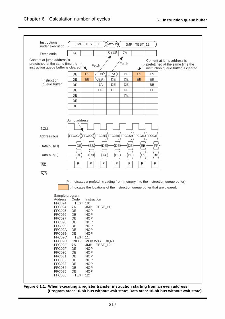
317
6.1 Instruction queue bufferChapter 6 Calculation number of cycles
Fetch code
Instructions under execution
Instruction queue buffer
Address bus
Data bus(H)
Data bus(L)
Fetch Fetch Content at jump address is prefetched at the same time the instruction queue buffer is cleared.
Jump address
Content at jump address is prefetched at the same time the instruction queue buffer is cleared.
Sample programAddress Code InstructionFFC024 TEST_10:FFC024 7A JMP TEST_11FFC025 DE NOPFFC026 DE NOPFFC027 DE NOPFFC028 DE NOPFFC029 DE NOPFFC02A DE NOPFFC02B DE NOPFFC02C TEST_11:FFC02C C9EB MOV.W:G R0,R1FFC02E 7A JMP TEST_12FFC02F DE NOPFFC030 DE NOPFFC031 DE NOPFFC032 DE NOPFFC033 DE NOPFFC034 DE NOPFFC035 DE NOPFFC036 TEST_12:
7A C9EB 7A
JMP TEST_11 MOV.W JMP TEST_12
DE
DE
DE
DE
DE
DE
DE
WR
RD
BCLK
C9
EB
C9
EB
7A
DE
DE
DE
DE
DE
DE
7A
DE
DE
DE
C9
EB
C9
EB
BB
FF
P P PP P P P
FFC02A FFC02C FFC02E FFC030 FFC032 FFC036 FFC038
DE EB DE DE DE EB FF
DE C9 7A DE DE C9 BB
: Indicates the locations of the instruction queue buffer that are cleared.
P : Indicates a prefetch (reading from memory into the instruction queue buffer).
Figure 6.1.1. When executing a register transfer instruction starting from an even address(Program area: 16-bit bus without wait state; Data area: 16-bit bus without wait state)
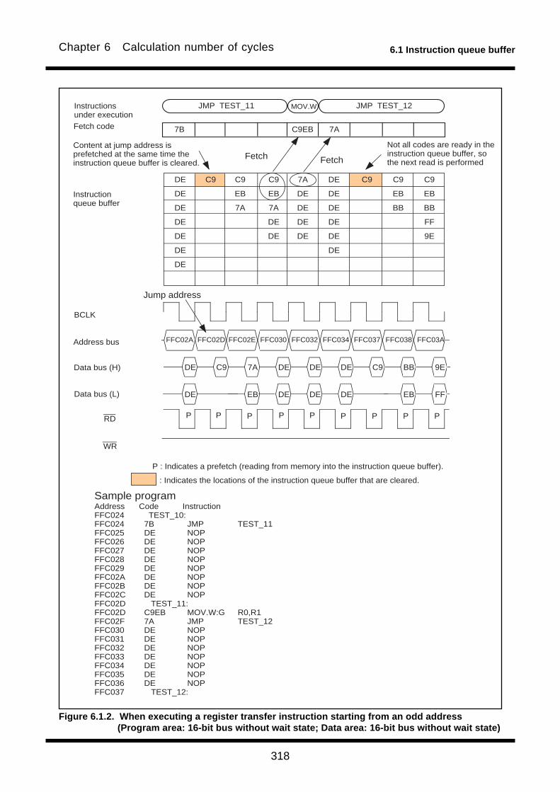
318
6.1 Instruction queue bufferChapter 6 Calculation number of cycles
Figure 6.1.2. When executing a register transfer instruction starting from an odd address(Program area: 16-bit bus without wait state; Data area: 16-bit bus without wait state)
Not all codes are ready in the instruction queue buffer, so the next read is performed
Fetch code
Instructions under execution
Address bus
Data bus (H)
Data bus (L)
BCLK
FetchFetchContent at jump address is prefetched at the same time the instruction queue buffer is cleared.
Instruction queue buffer
Jump address
Sample programAddress Code InstructionFFC024 TEST_10:FFC024 7B JMP TEST_11FFC025 DE NOPFFC026 DE NOPFFC027 DE NOPFFC028 DE NOPFFC029 DE NOPFFC02A DE NOPFFC02B DE NOPFFC02C DE NOPFFC02D TEST_11:FFC02D C9EB MOV.W:G R0,R1FFC02F 7A JMP TEST_12FFC030 DE NOPFFC031 DE NOPFFC032 DE NOPFFC033 DE NOPFFC034 DE NOPFFC035 DE NOPFFC036 DE NOPFFC037 TEST_12:
7B C9EB 7A
JMP TEST_11 MOV.W JMP TEST_12
DE
DE
DE
DE
DE
DE
DE
WR
RD
C9 C9
EB
7A
DE
DE
DE
DE
DE
DE
DE
DE
7A
DE
DE
DE
DE
C9C9
EB
7A
C9
EB
BB
FF
9E
C9
EB
BB
DE C9 7A DE DE DE C9 BB 9E
DE EB DE DE DE EB FF
FFC02A FFC02D FFC02E FFC030 FFC032 FFC034 FFC037 FFC038 FFC03A
P P PP P P P P P
: Indicates the locations of the instruction queue buffer that are cleared.
P : Indicates a prefetch (reading from memory into the instruction queue buffer).

319
6.1 Instruction queue bufferChapter 6 Calculation number of cycles
Content at jump address is prefetched at the same time the instruction queue buffer is cleared.
Fetch code
Instructions under execution
Instruction queue buffer
Address bus
Data bus (H)
Data bus (L)
Fetch
Jump address
DR : Indicates a data read.: Indicates the locations of the instruction queue buffer that are cleared.
P : Indicates a prefetch (reading from memory into the instruction queue buffer).
FetchFetch
Content at address 200116
Sample programAddress Code InstructionFFC024 TEST_10:FFC024 7A JMP TEST_11FFC025 DE NOPFFC026 DE NOPFFC027 DE NOPFFC028 DE NOPFFC029 DE NOPFFC02A DE NOPFFC02B DE NOPFFC02C TEST_11:FFC02C B9FB0020 MOV.W:G 02000h,R1FFC030 7A JMP TEST_12FFC031 DE NOPFFC032 DE NOPFFC033 DE NOPFFC034 DE NOPFFC035 DE NOPFFC036 DE NOPFFC037 DE NOPFFC038 TEST_12:
7A B9FB 7A
JMP TEST_11 MOV.W JMP TEST_12
DE
DE
DE
DE
DE
DE
DE
WR
RD
BCLK
B9
FB
00
20
7A
DE
7A
DE
DE
DE
7A
DE
DE
DE
DE
DE
DE
B9
FB
00
20
B9
FB
00
20
B9
FB
DE FB 20 DE AA DE DE FB 20
FFC02A FFC02C FFC02E FFC030 02000 FFC032 FFC034 FFC038 FFC03A
P DR PP P P P P P
0020
DE 00 7A AA DE B9 00B9 DE
Content at address 200016
Content at jump address is prefetched at the same time the instruction queue buffer is cleared.
Figure 6.1.3. When executing an instruction to read from even addresses starting from an even address(Program area: 16-bit bus without wait state; Data area: 16-bit bus without wait state)
320
6.1 Instruction queue bufferChapter 6 Calculation number of cycles
Figure 6.1.4. When executing an instruction to read from odd addresses starting from an even address(Program area: 16-bit bus without wait state; Data area: 16-bit bus without wait state)
Content at jump address is prefetched at the same time the instruction queue buffer is cleared.
Fetch code
Instructions under execution
Instruction queue buffer
Address bus
Data bus (H)
Data bus (L)
Fetch
Jump address
FetchFetch
Content at address 200116
7A B9FB 7A
JMP TEST_11 MOV.W JMP TEST_12
DE
DE
DE
DE
DE
DE
DE
B9
FB
01
20
7A
DE
7A
DE
DE
DE
7A
DE
DE
DE
DE
DE
DE
B9
FB
01
20
B9
FB
01
20
B9
FB
0020
Content at address 200216
Content at jump address is prefetched at the same time the instruction queue buffer is cleared.
Sample programAddress Code InstructionFFC024 TEST_10:FFC024 7A JMP TEST_11FFC025 DE NOPFFC026 DE NOPFFC027 DE NOPFFC028 DE NOPFFC029 DE NOPFFC02A DE NOPFFC02B DE NOPFFC02C TEST_11:FFC02C B9FB0120 MOV.W:G 02001h,R1FFC030 7A JMP TEST_12FFC031 DE NOPFFC032 DE NOPFFC033 DE NOPFFC034 DE NOPFFC035 DE NOPFFC036 DE NOPFFC037 DE NOPFFC038 TEST_12:
WR
RD
BCLK
DE FB 20 DE AA DE DE FB 20
DE 01 7A AA DE B9 01B9 DE
FFC02A FFC02C FFC02E FFC030 02001 FFC032 FFC034 FFC038 FFC03A02002
P DR DRP P P P P P P
7A
DE
DR : Indicates a data read.
: Indicates the locations of the instruction queue buffer that are cleared.
P : Indicates a prefetch (reading from memory into the instruction queue buffer).
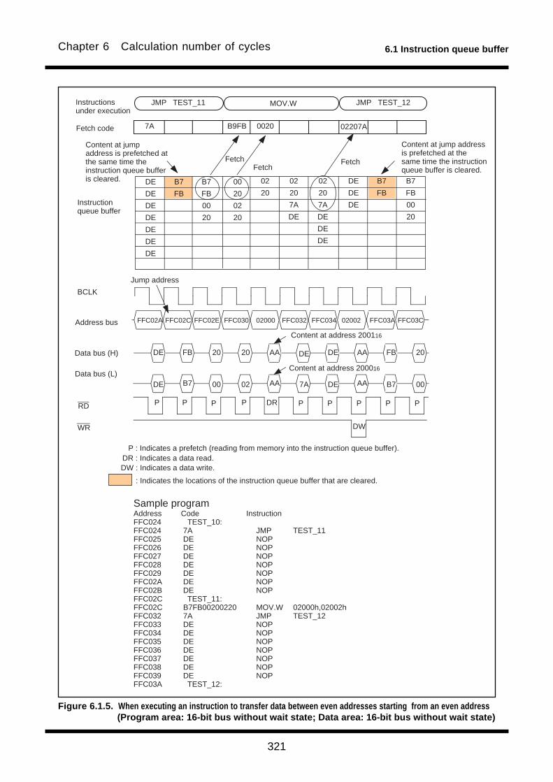
321
6.1 Instruction queue bufferChapter 6 Calculation number of cycles
Figure 6.1.5. When executing an instruction to transfer data between even addresses starting from an even address(Program area: 16-bit bus without wait state; Data area: 16-bit bus without wait state)
02
20
7A
DE
DE
DE
02
20
7A
DE
DE
DE
DE
B7
FB
00
20
B7
FB
02
20
Content at jump address is prefetched at the same time the instruction queue buffer is cleared.
Fetch code
Instructions under execution
Instruction queue buffer
Address bus
Data bus (H)
Data bus (L)
Fetch
Jump address
DR : Indicates a data read.
: Indicates the locations of the instruction queue buffer that are cleared.
P : Indicates a prefetch (reading from memory into the instruction queue buffer).
FetchFetch
Content at address 200116
7A B9FB
JMP TEST_11 MOV.W JMP TEST_12
DE
DE
DE
DE
DE
DE
DE
B7
FB
00
20
02
20
B7
FB
00
20
0020
Content at address 200016
Content at jump address is prefetched at the same time the instruction queue buffer is cleared.
BCLK
Sample programAddress Code InstructionFFC024 TEST_10:FFC024 7A JMP TEST_11FFC025 DE NOPFFC026 DE NOPFFC027 DE NOPFFC028 DE NOPFFC029 DE NOPFFC02A DE NOPFFC02B DE NOPFFC02C TEST_11:FFC02C B7FB00200220 MOV.W 02000h,02002hFFC032 7A JMP TEST_12FFC033 DE NOPFFC034 DE NOPFFC035 DE NOPFFC036 DE NOPFFC037 DE NOPFFC038 DE NOPFFC039 DE NOPFFC03A TEST_12:
02207A
WR
RD
FFC02A FFC02C FFC02E FFC030 02000 FFC034 02002 FFC03A FFC03CFFC032
P DR PP P P P P P P
DE 00 02 7A DE B7 00B7 AAAA
DE FB 20 20 AA DE AA FB 20DE
DW
DW : Indicates a data write.

322
6.1 Instruction queue bufferChapter 6 Calculation number of cycles
Content at jump address is prefetched at the same time the instruction queue buffer is cleared.
Fetch code
Instructions under execution
Instruction queue buffer
Address bus
Data bus (H)
Data bus (L)
Fetch
Jump address
DR : Indicates a data read.: Indicates the locations of the instruction queue buffer that are cleared.
P : Indicates a prefetch (reading from memory into the instruction queue buffer).
FetchFetch
Content at address 200116
7A B9FB 7A
JMP TEST_11 MOV.W JMP TEST_12
DE
DE
DE
DE
DE
DE
DE
WR
RD
BCLK
B9
FB
00
20
7A
DE
7A
DE
DE
DE
7A
DE
DE
DE
DE
DE
DE
B9
FB
00
20
B9
FB
00
20
B9
FB
DE FB 20 DE AA DE DE FB 20
P DR PP P P P P P
0020
DE 00 7A AA DE B9 00B9 DE
Content at address 200016
Content at jump address is prefetched at the same time the instruction queue buffer is cleared.
Sample programAddress Code InstructionFFC026 TEST_10:FFC026 7A JMP TEST_11FFC027 DE NOPFFC028 DE NOPFFC029 DE NOPFFC02A DE NOPFFC02B DE NOPFFC02C DE NOPFFC02D DE NOPFFC02E TEST_11:FFC02E B9FB0020 MOV.W:G 02000h,R1FFC032 7A JMP TEST_12FFC033 DE NOPFFC034 DE NOPFFC035 DE NOPFFC036 DE NOPFFC037 DE NOPFFC038 DE NOPFFC039 DE NOPFFC03A TEST_12:
FFC02C FFC02E FFC030 FFC032 02000 FFC034 FFC036 FFC03A FFC03C
Figure 6.1.6. When executing an instruction to read from even addresses starting from an even address(Program area: 16-bit bus without wait state; Data area: 16-bit bus with wait state)
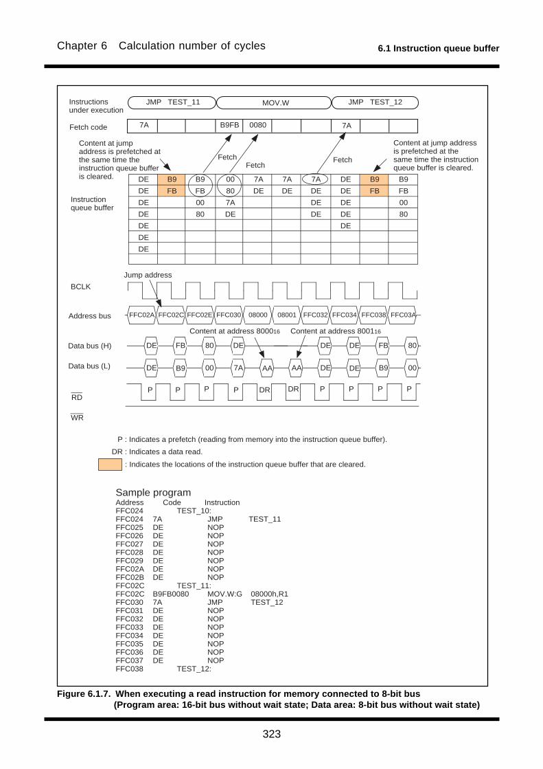
323
6.1 Instruction queue bufferChapter 6 Calculation number of cycles
Content at jump address is prefetched at the same time the instruction queue buffer is cleared.
Fetch code
Instructions under execution
Instruction queue buffer
Address bus
Data bus (H)
Data bus (L)
Fetch
Jump address
DR : Indicates a data read.
: Indicates the locations of the instruction queue buffer that are cleared.
P : Indicates a prefetch (reading from memory into the instruction queue buffer).
FetchFetch
7A B9FB
JMP TEST_11 MOV.W JMP TEST_12
DE
DE
DE
DE
DE
DE
DE
0080
Content at jump address is prefetched at the same time the instruction queue buffer is cleared.
BCLK
7A
WR
RD
Sample programAddress Code InstructionFFC024 TEST_10:FFC024 7A JMP TEST_11FFC025 DE NOPFFC026 DE NOPFFC027 DE NOPFFC028 DE NOPFFC029 DE NOPFFC02A DE NOPFFC02B DE NOPFFC02C TEST_11:FFC02C B9FB0080 MOV.W:G 08000h,R1FFC030 7A JMP TEST_12FFC031 DE NOPFFC032 DE NOPFFC033 DE NOPFFC034 DE NOPFFC035 DE NOPFFC036 DE NOPFFC037 DE NOPFFC038 TEST_12:
B9
FB
00
80
7A
DE
7A
DE
DE
DE
7A
DE
DE
DE
DE
DE
DE
B9
FB
00
80
B9
FB
00
80
B9
FB
7A
DE
DE FB 80 DE DE DE FB 80
AADE 00 7A AA DE B9 00B9 DE
FFC02A FFC02C FFC02E FFC030 08000 FFC032 FFC034 FFC038 FFC03A08001
P DR DRP P P P P P P
Content at address 800016 Content at address 800116
Figure 6.1.7. When executing a read instruction for memory connected to 8-bit bus(Program area: 16-bit bus without wait state; Data area: 8-bit bus without wait state)
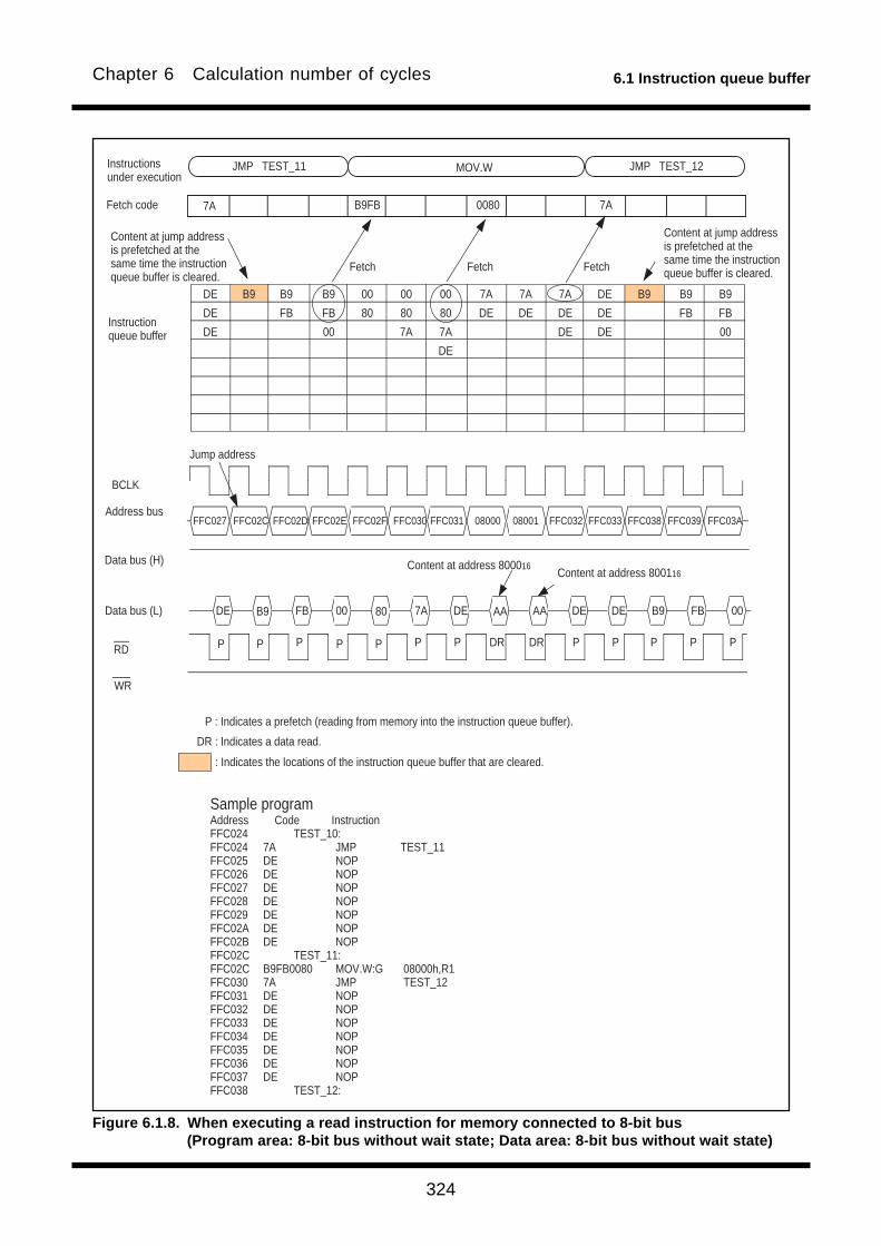
324
6.1 Instruction queue bufferChapter 6 Calculation number of cycles
Jump address
Sample programAddress Code InstructionFFC024 TEST_10:FFC024 7A JMP TEST_11FFC025 DE NOPFFC026 DE NOPFFC027 DE NOPFFC028 DE NOPFFC029 DE NOPFFC02A DE NOPFFC02B DE NOPFFC02C TEST_11:FFC02C B9FB0080 MOV.W:G 08000h,R1FFC030 7A JMP TEST_12FFC031 DE NOPFFC032 DE NOPFFC033 DE NOPFFC034 DE NOPFFC035 DE NOPFFC036 DE NOPFFC037 DE NOPFFC038 TEST_12:
7A B9FB 7A
DE
DE
DE
WR
RD
BCLK
B9 B9
FB
00
00
80
7A
DE
00
80
7A
7A
DE
B9
FB
7A
DE
DE
7A
DE
0080
00
80
B9DE
DE
DE
B9
FB
B9
FB
00
FFC027 FFC02C FFC02D FFC02E FFC02F FFC031 08000 08001 FFC032FFC030 FFC033 FFC038 FFC039 FFC03A
80DE FB 00 7A DE AA DEB9 AA DE B9 FB 00
P P PP P P P DR DR P P P P P
Content at jump address is prefetched at the same time the instruction queue buffer is cleared.
Content at jump address is prefetched at the same time the instruction queue buffer is cleared.Fetch Fetch Fetch
Content at address 800016Content at address 800116
Fetch code
Instructions under execution
Instruction queue buffer
Address bus
Data bus (H)
Data bus (L)
DR : Indicates a data read.
: Indicates the locations of the instruction queue buffer that are cleared.
P : Indicates a prefetch (reading from memory into the instruction queue buffer).
JMP TEST_11 MOV.W JMP TEST_12
Figure 6.1.8. When executing a read instruction for memory connected to 8-bit bus(Program area: 8-bit bus without wait state; Data area: 8-bit bus without wait state)

Q&A-1
Q & AInformation in a Q&A form to be used to make the most of the M16C family is given below.
Usually, one question and the answer to it are given on one page; the upper section is for the
question, and the lower section is for the answer (if a pair of question and answer extends over two
or more pages, a page number is given at the lower-right corner).
Functions closely connected with the contents of a page are shown at its upper-right corner.
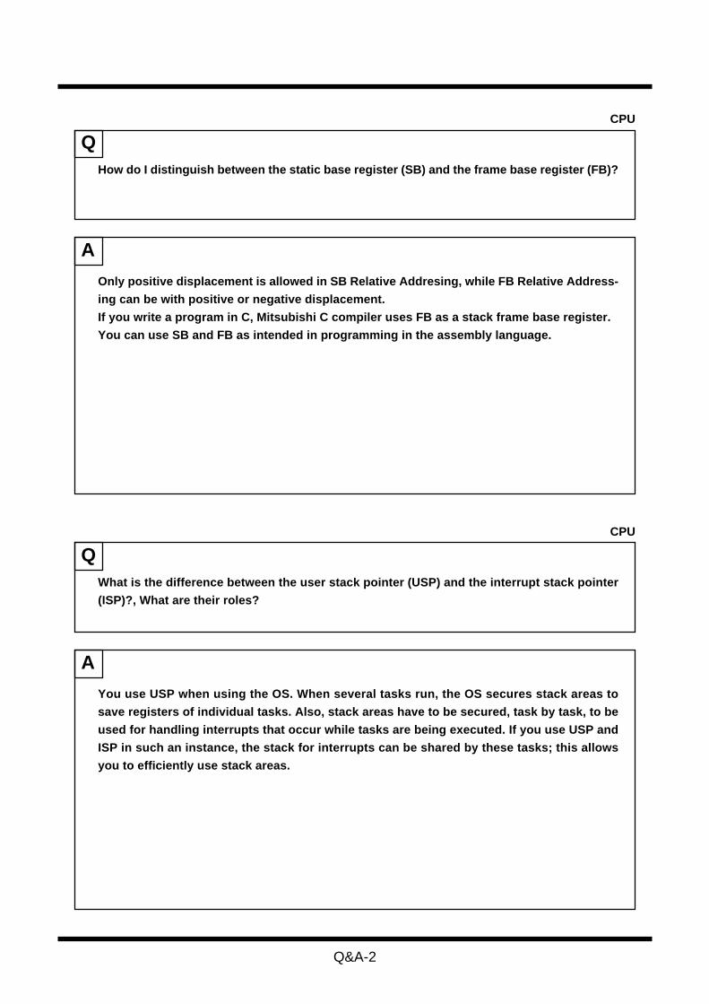
Q&A-2
CPU
Q
A
Only positive displacement is allowed in SB Relative Addresing, while FB Relative Address-
ing can be with positive or negative displacement.
If you write a program in C, Mitsubishi C compiler uses FB as a stack frame base register.
You can use SB and FB as intended in programming in the assembly language.
How do I distinguish between the static base register (SB) and the frame base register (FB)?
CPU
Q
A
What is the difference between the user stack pointer (USP) and the interrupt stack pointer
(ISP)?, What are their roles?
You use USP when using the OS. When several tasks run, the OS secures stack areas to
save registers of individual tasks. Also, stack areas have to be secured, task by task, to be
used for handling interrupts that occur while tasks are being executed. If you use USP and
ISP in such an instance, the stack for interrupts can be shared by these tasks; this allows
you to efficiently use stack areas.

Q&A-3
CPU
Q
A
What is the difference between the DIV instruction and the DIVX instruction?
Either of the DIV instruction and the DIVX instruction is an instruction for signed division,
the sign of the remainder is different.
The sign of the remainder left after the DIV instruction is the same as that of the dividend, on
the contrary, the sign of the remainder of the DIVX instruction is the same as that of the
divisor.
In general, the following relation among quotient, divisor, dividend, and remainder holds.
dividend = divisor quotient + remainder
Since the sign of the remainder is different between these instructions, the quotient ob-
tained either by dividing a positive integer by a negative integer or by dividing a negative
integer by a positive integer using the DIV instruction is different from that obtained using
the DIVX instruction.
For example, dividing 10 by –3 using the DIV instruction yields –3 and leaves +1, while doing
the same using the DIVX instruction yields –4 and leaves –2.
Dividing –10 by +3 using the DIV instruction yields –3 and leaves –1, while doing the same
using the DIVX instruction yields –4 and leaves +2.

Q&A-4
Interrupt
Q
A
Yes. But there can be a chance that the microcomputer runs away out of control if an inter-
rupt request occurs in changing the value of INTB. So it is not recommended to frequently
change the value of INTB while a program is being executed.
Is it possible to change the value of the interrupt table register (INTB) while a program is
being executed?

Symbol-1
Table of symbolsSymbols used in this software manual are explained below. They are good in this manual only.

Symbol-2
Symbol Meaning
Transposition from the right side to the left side
Interchange between the right side and the left side
Addition
Subtraction
Multiplication
Division
Logical conjunction
Logical disjunction
Exclusive disjunction
Logical negation
dsp24 24-bit displacement
dsp16 16-bit displacement
dsp8 8-bit displacement
EVA( ) An effective address indicated by what is enclosed in ( )
EXTS( ) Sign extension indicated by what is enclosed in ( )
EXTZ( ) Zero extension indicated by what is enclosed in ( )
(HH) Higher-order byte of higher-order word of a register or memory (highest byte)
H4: Four higher-order bits of an 8-bit register or 8-bit memory
(HL) Lower-order byte of higher-order word of a register or memory
Absolute value
(LH) Higher-order byte of lower-order word of a register or memory
(LL) Lower-order byte of lower-order word of a register or memory (lowest byte)
L4: Four lower-order bits of an 8-bit register or 8-bit memory
LSB Least Significant Bit
M( ) Content of memory indicated by what is enclosed in ( )
MSB Most Significant Bit
PCH Higher-order byte of the program counter
PCML Middle-order byte and lower-order byte of the program counter
FLGH Four higher-order bits of the flag register
FLGL Eight lower-order bits of the flag register
[ ] Indirect addressing
<
<
A

Glossary-1
GlossaryTechnical terms used in this software manual are explained below. They are good in this manual only.

Glossary-2
borrow Tomove a digit to the next lower position. carry
carry Tomove a digit to the next higher position. borrow
context Registers that a program uses.
decimal addition An addition in terms of decimal system.
displacement The difference between the initial position and later
position.
effective address An after-modification address to be actually used.
LSB Abbreviation for Least Significant Biit MSB
The bit occupying the lowest-order position of a data item.
Term Meaning Related word
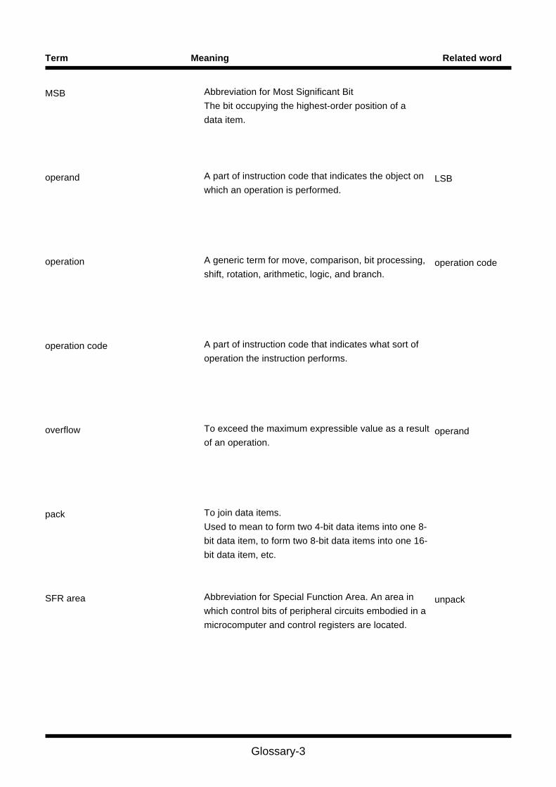
Glossary-3
Term Meaning Related word
MSB
operand
operation
operation code
overflow
pack
SFR area
Abbreviation for Most Significant Bit
The bit occupying the highest-order position of a
data item.
A part of instruction code that indicates the object on
which an operation is performed.
A generic term for move, comparison, bit processing,
shift, rotation, arithmetic, logic, and branch.
A part of instruction code that indicates what sort of
operation the instruction performs.
To exceed the maximum expressible value as a result
of an operation.
To join data items.
Used to mean to form two 4-bit data items into one 8-
bit data item, to form two 8-bit data items into one 16-
bit data item, etc.
Abbreviation for Special Function Area. An area in
which control bits of peripheral circuits embodied in a
microcomputer and control registers are located.
LSB
operation code
operand
unpack

Glossary-4
Term Meaning Related word
shift out
sign bit
sign extension
stack frame
string
unpack
zero extension
To move the content of a register either to the right or
left until fully overflowed.
A bit that indicates either a positive or a negative (the
highest-order bit).
To extend a data length in which the higher-order to be
extended are made to have the same sign of the sign
bit. For example, sign-extending FF16 results in
FFFF16, and sign-extending 0F16 results in 000F16.
An area for automatic variables the functions of the C
language use.
A sequence of characters.
To restore combined items or packed information to
the original form. Used to mean to separate 8-bit
information into two parts — 4 lower-order bits and
four higher-order bits, to separate 16-bit information
into two parts — 8 lower-order bits and 8 higher-order
bits, or the like.
To extend a data length by turning higher-order bits to
0's. For example, zero-extending FF16 to 16 bits
results in 00FF16.
pack

Index-1
IndexA
A0 and A1 ••• 5
A1A0 ••• 5
Address register ••• 5
Address space ••• 3
Addressing mode ••• 22
B
B flag ••• 6
Byte (8-bit) data ••• 16
C
C flag ••• 6
Carry flag ••• 6
Cycles ••• 139
D
D flag ••• 6
Data arrangement in memory ••• 17
Data arrangement in Register ••• 16
Data register ••• 4
Data type ••• 10
Debug flag ••• 6
Description example ••• 37
dest ••• 18
F
FB ••• 5
Fixed vector table ••• 19
Flag change ••• 37
Flag register ••• 5
FLG ••• 5
Frame base register ••• 5
Function ••• 37
I
Interrupt table register ••• 5
I flag ••• 6
Instruction code ••• 139
Instruction Format ••• 18
Instruction format specifier ••• 35
INTB ••• 5
Integer ••• 10
Interrupt enable flag ••• 6
Interrupt stack pointer ••• 5
Interrupt vector table ••• 19
IPL ••• 7
ISP ••• 5
L
Long word (32-bit) data ••• 16
M
Maskable interrupt ••• 248
Memory bit ••• 12
Mnemonic ••• 35, 38
N
Nibble (4-bit) data ••• 16
Nonmaskable interrupt ••• 248
O
O flag ••• 6
Operand ••• 35, 38
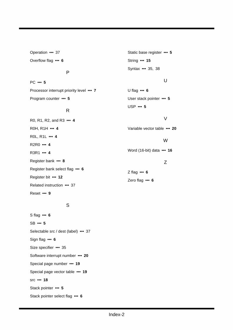
Index-2
Operation ••• 37
Overflow flag ••• 6
P
PC ••• 5
Processor interrupt priority level ••• 7
Program counter ••• 5
R
R0, R1, R2, and R3 ••• 4
R0H, R1H ••• 4
R0L, R1L ••• 4
R2R0 ••• 4
R3R1 ••• 4
Register bank ••• 8
Register bank select flag ••• 6
Register bit ••• 12
Related instruction ••• 37
Reset ••• 9
S
S flag ••• 6
SB ••• 5
Selectable src / dest (label) ••• 37
Sign flag ••• 6
Size specifier ••• 35
Software interrupt number ••• 20
Special page number ••• 19
Special page vector table ••• 19
src ••• 18
Stack pointer ••• 5
Stack pointer select flag ••• 6
Static base register ••• 5
String ••• 15
Syntax ••• 35, 38
U
U flag ••• 6
User stack pointer ••• 5
USP ••• 5
V
Variable vector table ••• 20
W
Word (16-bit) data ••• 16
Z
Z flag ••• 6
Zero flag ••• 6

Revision history-1
Contents for changeRevision
date
Version
Revision historyM16C/80 Series
Software Manual
Revision History
'99.1.26Chapter 5 addition
• Page 20 line 20
(IPL) --> (ISP)
• Page 32 Absolute
000FFF16 --> 000FFFF16
• Page 95 JMPS Operation
FFFFFE16 --> FFFE16
• Page 96 JSR Operation
SP - 1 --> SP - 2
• Page 98 JMRS Operation
FFFFFE16 --> FFFE16
• Page 133 SCMPU Operation
temp --> tmp
• Page 276 SCCnd dest An
--- --> ---/A0/---
--- --> ---/A1/---
• Page 4 line 2
13 registers --> 28 registers
• Page 89 INDEXType
[ Description Example ]
INDEXB R0 --> INDEXB.W R0
INDEXLS [A0] --> INDEXLS.B [A0]
• Page 138-143 SIN, SMOVB, SMOVF, SOUT, SSTR
[ Operation ]
Delate 'Repeat' and 'Until ...'
• Page 62- BRK, BRK2, ENTER, EXITD, INT, INTO, POPC, POPM, REIT, RTS, UND
Note for PCH, FBH and M(SP) is added.
• Page 120 PUSH
*2 The 8 high-order bits are 0 --> indeterminate
• Page 133 SCMPU
• When the size specifier (.size) is (.W)
If M(A)=M(A1) then M(A0+1)–M(A1+1) -->
If M(A)=M(A1) and M(A0)≠0 then M(A0+1)–M(A1+1)
• Page 135 SHA
[ Flag change ] O
• Page 173 (4) Table of cycles
• Page 268 PUSHM [ Byte number/ cycle number ]
1/m --> 2/m
• Page 5 (9) Save flag register
24 bits --> 16 bits
REV.C
'99.1.26
'99.3.12
'99.712
Revision History
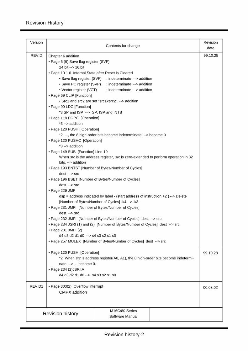
Revision history-2
Contents for changeRevision
date
Version
Revision historyM16C/80 Series
Software Manual
Revision History
99.10.25REV.D Chapter 6 addition
• Page 5 (9) Save flag register (SVF)
24 bit --> 16 bit
• Page 10 1.6 Internal State after Reset is Cleared
• Save flag register (SVF) : indeterminate --> addition
• Save PC register (SVP) : indeterminate --> addition
• Vector register (VCT) : indeterminate --> addition
• Page 69 CLIP [Function]
• Src1 and src2 are set "src1<src2". --> addition
• Page 99 LDC [Function]
*3 SP and ISP --> SP, ISP and INTB
• Page 118 POPC [Operation]
*3 --> addition
• Page 120 PUSH [ Operation]
*2 ..., the 8 high-order bits become indeterminate. --> become 0
• Page 120 PUSHC [Operation]
*3 --> addition
• Page 149 SUB [Function] Line 10When src is the address register, src is zero-extended to perform operation in 32bits. --> addition
• Page 193 BNTST [Number of Bytes/Number of Cycles]
dest --> src
• Page 196 BSET [Number of Bytes/Number of Cycles]
dest --> src
• Page 229 JMP
dsp = address indicated by label - (start address of instruction +2 ) --> Delete
[Number of Bytes/Number of Cycles] 1/4 --> 1/3
• Page 231 JMPI [Number of Bytes/Number of Cycles]
dest --> src
• Page 232 JMPI [Number of Bytes/Number of Cycles] dest --> src
• Page 234 JSRI (1) and (2) [Number of Bytes/Number of Cycles] dest --> src
• Page 231 JMPI (2)
d4 d3 d2 d1 d0 --> s4 s3 s2 s1 s0
• Page 257 MULEX [Number of Bytes/Number of Cycles] dest --> src
• Page 120 PUSH [Operation]
*2 When src is address register(A0, A1), the 8 high-order bits become indetermi-
nate. --> ... become 0.
• Page 234 (2)JSRI.A
d4 d3 d2 d1 d0 --> s4 s3 s2 s1 s0
• Page 303(2) Overflow interrupt
CMPX addition
99.10.28
00.03.02REV.D1

Keep safety first in your circuit designs!
Notes regarding these materials
● Mitsubishi Electric Corporation puts the maximum effort into making semiconductorproducts better and more reliable, but there is always the possibility that trouble mayoccur with them. Trouble with semiconductors may lead to personal injury, fire orproperty damage. Remember to give due consideration to safety when making yourcircuit designs, with appropriate measures such as (i) placement of substitutive,auxiliary circuits, (ii) use of non-flammable material or (iii) prevention against anymalfunction or mishap.
● These materials are intended as a reference to assist our customers in the selectionof the Mitsubishi semiconductor product best suited to the customer's application;they do not convey any license under any intellectual property rights, or any otherrights, belonging to Mitsubishi Electric Corporation or a third party.
● Mitsubishi Electric Corporation assumes no responsibility for any damage, orinfringement of any third-party's rights, originating in the use of any product data,diagrams, charts, programs, algorithms, or circuit application examples contained inthese materials.
● All information contained in these materials, including product data, diagrams, charts,programs and algorithms represents information on products at the time of publicationof these materials, and are subject to change by Mitsubishi Electric Corporationwithout notice due to product improvements or other reasons. It is thereforerecommended that customers contact Mitsubishi Electric Corporation or an authorizedMitsubishi Semiconductor product distributor for the latest product information beforepurchasing a product listed herein.The information described here may contain technical inaccuracies or typographicalerrors. Mitsubishi Electric Corporation assumes no responsibility for any damage,liability, or other loss rising from these inaccuracies or errors.Please also pay attention to information published by Mitsubishi Electric Corporationby various means, including the Mitsubishi Semiconductor home page (http://www.mitsubishichips.com).
● When using any or all of the information contained in these materials, includingproduct data, diagrams, charts, programs, and algorithms, please be sure to evaluateall information as a total system before making a final decision on the applicability ofthe information and products. Mitsubishi Electric Corporation assumes noresponsibility for any damage, liability or other loss resulting from the informationcontained herein.
● Mitsubishi Electric Corporation semiconductors are not designed or manufacturedfor use in a device or system that is used under circumstances in which human life ispotentially at stake. Please contact Mitsubishi Electric Corporation or an authorizedMitsubishi Semiconductor product distributor when considering the use of a productcontained herein for any specific purposes, such as apparatus or systems fortransportation, vehicular, medical, aerospace, nuclear, or undersea repeater use.
● The prior written approval of Mitsubishi Electric Corporation is necessary to reprintor reproduce in whole or in part these materials.
● If these products or technologies are subject to the Japanese export controlrestrictions, they must be exported under a license from the Japanese governmentand cannot be imported into a country other than the approved destination.Any diversion or reexport contrary to the export control laws and regulations of Japanand/or the country of destination is prohibited.
● Please contact Mitsubishi Electric Corporation or an authorized Mitsubishi Semiconductor product distributor for further details on these materials or the products contained therein.

MITSUBISHI SEMICONDUCTORS
M16C SOFTWARE MANUAL Rev.D1
March First Edition 2000
Editioned by
Committee of editing of Mitsubishi Semiconductor
SOFTWARE MANUAL
Published by
Mitsubishi Electric Corp., Kitaitami Works
This book, or parts thereof, may not be reproduced in any form without
permission of Mitsubishi Electric Corporation.
©2000 MITSUBISHI ELECTRIC CORPORATION