Embed Size (px)
Citation preview
Buy-Ei.com
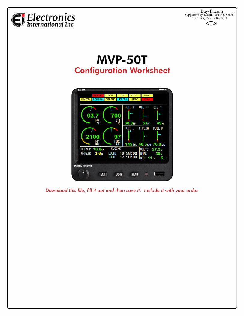
MVP-50T Configuration Worksheet
Download this file, fill it out and then save it. Include it with your order.
1001175, Rev. B, 09/27/[email protected] | (541) 318-6060
2
MVP-50T Configuration Worksheet Electronics International Inc.
General Info:
Aircraft Information: Example:
Customer Name: Peter Pilot
Customer Phone: 555-555-5555
Customer Email: [email protected]
Aircraft Make & Model: Pilatus, PC-6/B
Aircraft Tail Number: N5555H
Engine Mfg and Model Pratt, PT6A-6A
[ ] Include a Certificate of Conformance ($10.00)
[ ] Include an 8130-3 ($195.00). Can add up to two weeks to lead time.
All data must be verified for accuracy and must match the POH/AFM and any changes required by any AD’s, Supplements or STC’s. Also, limit and marking information must be cross-checked against the instruments mounted in the aircraft panel.
A configuration file for a TSO’d and/or STC’d MVP-50T can only be generated or changed by Electronics In-ternational Inc. If any of the information provided on this form is wrong, there may be a reprogramming fee to change the configuration.
Important Information: The information in this document must be verified for accuracy and match the air-craft’s hardware and POH/AFM marking requirements. If you have not ordered the probes and transducers to support the functions you have listed in this document, your order will be delayed. Also, if the data supplied in this document is incomplete or missing, your order will be delayed. Our mission is to get your order shipped as soon as possible.
Functions Included in the Kit:The following functions are included in the kit: Np, Ng, TQ, ITT, Fuel Flow, Fuel Level, FP, OT, OP, Volts, Amps and OAT. Other functions and annunciators may be added. Some functions require sensors, probes or modules and must be purchased, others are free. Annunciators require a VI-221 interface ($19.95 ea.).
The MVP-50T gets all its signals via an EDC-33T. Make sure you have the channels available on the EDC-33T to support your selections. An overview of the EDC-33T channels is provided in appendix A. The MVP-50T can accept data from two EDC-33T Engine Data Converters.
[ ] Add a second EDC-33T to the kit. ($2,450)
3
MVP-50T Configuration Worksheet Electronics International Inc.
Rules for Laying Out the Main and System Screens:The following rules will help you layout the Main and System screens that will meet our standardization re-quirements.
Main Screen, Annunciators:
On the top of the Main Screen are annunciators called a Crew Alerting System (CAS). There are two configura-tions. If 14 or less annunciators will be displayed, the bottom row will display Main Screen caution and warn-ings. If more than 14 will be displayed, a single Master Caution and Warning will be provide at the far left.
Main Screen, 4-Arc Gauges:
The 4-Arc Gauges are located on the left side of the Main Screen. They are setup as Ng, ITT, Np and TQ in that order (left to right, top to bottom). If Np is not displayed, Fuel Flow can be displayed in its place.
Main Screen 6-Horizontal Strip Gauges:
The 3-Strip Gauges in the top right portion of the Main Screen should be setup as Fuel P (or F. Flow), Oil P and Oil T in that order. The 2-Strip Gauges in the middle right portion of the Main Screen should be setup as Fuel L, F. Flow (or Fuel P.) and Fuel R in that order.
Main Screen 6-Digital Gauges:
Three Digital Gauges are located in the lower left portion of the Main Screen and three are located in the lower right portion of the Main Screen. Functions that require only a digital gauge can be placed here. The bottom right location is normally used for OAT. This location can display OAT in degrees C and in degrees F at the same time. Some functions that can be displayed in these locations are Amps, Volts, Boom P, Time to Empty, G-Meter, Hydraulic Pressure, Bleed Air, Oxgen P, Cabin P, Cabin Alt, Inverter and others. Also, these six loca-tions can be setup as Annunciators. Annunciators require a VI-221 Voltage Interface Module ($19.95 ea.).
System Screen, Rudder, Elevator, Aileron, Flap and Gear Indicators:
The top of the System Screen provides Rudder, Elevator, Aileron, Flap and Gear Indicators. If Gear status and airspeed are monitored, the MVP-50T system will provide a gear-up warning. These indicators are only back-ups for the primary indicators in the aircraft.
System Screen, 7-Digital Gauges (or Annunciators):
There are 7-Digital Gauges in the lower left portion of the System Screen. These gauges can also be setup to display annunciators.
System Screen, 4-Strip Gauges (or Annunciators):
There are 4-Strip Gauges in the lower middle portion of the System Screen.
If any of the gauges on the System Screen displays a function in red or yellow, the “SYS SCR” Annunciator on the Main Screen will blink in the color of the alert.
4
MVP-50T Configuration Worksheet Electronics International Inc.
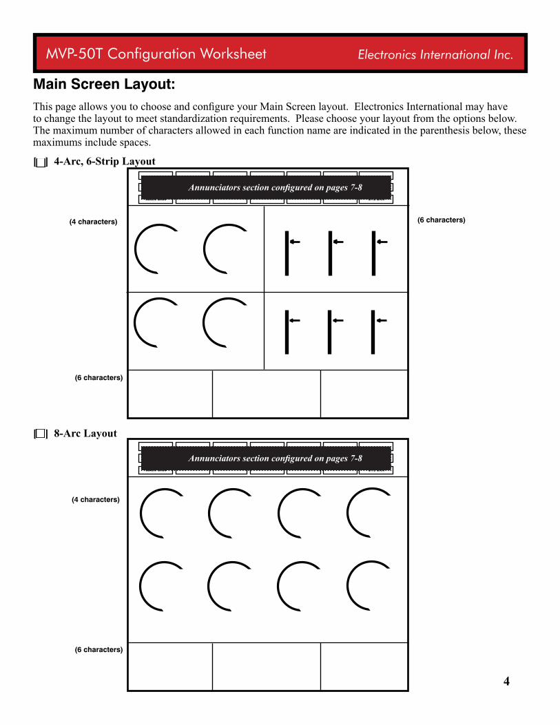
Main Screen Layout:This page allows you to choose and configure your Main Screen layout. Electronics International may have to change the layout to meet standardization requirements. Please choose your layout from the options below. The maximum number of characters allowed in each function name are indicated in the parenthesis below, these maximums include spaces. [ ] 4-Arc, 6-Strip Layout
[ ] 8-Arc Layout
MAIN SRN SYS SRN
MAIN SRN SYS SRN
(6 characters)
(6 characters)
(4 characters)
(6 characters)
(4 characters)
Annunciators section configured on pages 7-8
Annunciators section configured on pages 7-8
5
MVP-50T Configuration Worksheet Electronics International Inc.
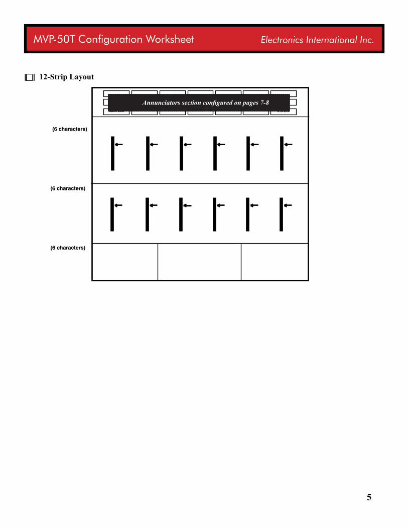
[ ] 12-Strip Layout
MAIN SRN SYS SRN
(6 characters)
(6 characters)
(6 characters)
Annunciators section configured on pages 7-8
6
MVP-50T Configuration Worksheet Electronics International Inc.
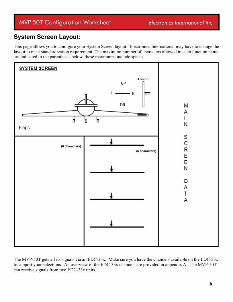
System Screen Layout:This page allows you to configure your System Screen layout. Electronics International may have to change the layout to meet standardization requirement. The maximum number of characters allowed in each function name are indicated in the parenthesis below, these maximums include spaces.
The MVP-50T gets all its signals via an EDC-33x. Make sure you have the channels available on the EDC-33x to support your selections. An overview of the EDC-33x channels are provided in appendix A. The MVP-50T can receive signals from two EDC-33x units.
(6 characters)
(6 characters)
7
MVP-50T Configuration Worksheet Electronics International Inc.
Provide Limit, Range and Signal Information:For each of the functions placed on the Main and System Screens, provide information to allow the EDC-33x to interface to the provided signals and the MVP-50T to display proper range and limits.
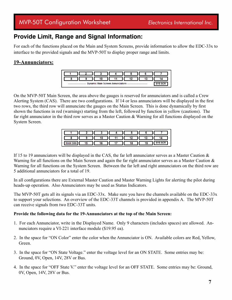
19-Annunciators:
On the MVP-50T Main Screen, the area above the gauges is reserved for annunciators and is called a Crew Alerting System (CAS). There are two configurations. If 14 or less annunciators will be displayed in the first two rows, the third row will annunciate the gauges on the Main Screen. This is done dynamically by first shown the functions in red (warnings) starting from the left, followed by function in yellow (cautions). The far right annunciator in the third row serves as a Master Caution & Warning for all functions displayed on the System Screen.
If 15 to 19 annunciators will be displayed in the CAS, the far left annunciator serves as a Master Caution & Warning for all functions on the Main Screen and again the far right annunciator serves as a Master Caution & Warning for all functions on the System Screen. Between the far left and right annunciators on the third row are 5 additional annunciators for a total of 19.
In all configurations there are External Master Caution and Master Warning Lights for alerting the pilot during heads-up operation. Also Annunciators may be used as Status Indicators.
The MVP-50T gets all its signals via an EDC-33x. Make sure you have the channels available on the EDC-33x to support your selections. An overview of the EDC-33T channels is provided in appendix A. The MVP-50T can receive signals from two EDC-33T units.
Provide the following data for the 19-Annunciators at the top of the Main Screen:
1. For each Annunciator, write in the Displayed Name. Only 9 characters (includes spaces) are allowed. An-nunciators require a VI-221 interface module ($19.95 ea).
2. In the space for “ON Color” enter the color when the Annunciator is ON. Available colors are Red, Yellow, Green.
3. In the space for “ON State Voltage.” enter the voltage level for an ON STATE. Some entries may be: Ground, 0V, Open, 14V, 28V or Bus.
4. In the space for “OFF State V.” enter the voltage level for an OFF STATE. Some entries may be: Ground, 0V, Open, 14V, 28V or Bus.
SYS SCR
SYS SCR
8
MVP-50T Configuration Worksheet Electronics International Inc.
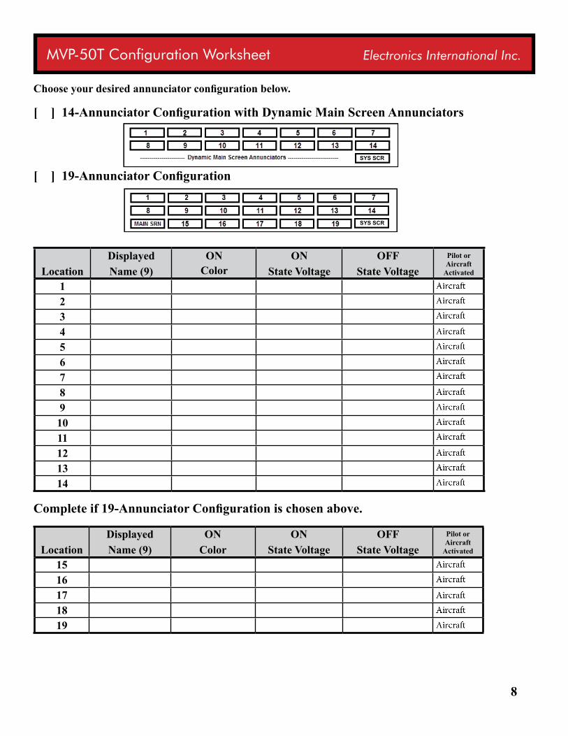
Choose your desired annunciator configuration below.
[ ] 14-Annunciator Configuration with Dynamic Main Screen Annunciators
[ ] 19-Annunciator Configuration
LocationDisplayedName (9)
ONColor
ONState Voltage
OFFState Voltage
Pilot or Aircraft
Activated
1234567891011121314
Complete if 19-Annunciator Configuration is chosen above.
LocationDisplayedName (9)
ONColor
ONState Voltage
OFFState Voltage
Pilot or Aircraft
Activated
1516171819
SYS SCR
SYS SCR
9
MVP-50T Configuration Worksheet Electronics International Inc.
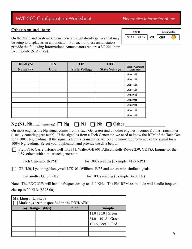
Other Annunciators:
On the Main and System Screens there are digital-only gauges that may be setup to display as an annunciator. For each of these annunciators provide the following information: Annunciators require a VI-221 inter-face module ($19.95 ea).
DisplayedName (9)
ONColor
ONState Voltage
OFFState Voltage
Pilot or Aircraft Activated
Ng (N1, Nh, ....) (Select one): [ ] Ng [ ] N1 [ ] Nh [ ] Other __________________ On most engines the Ng signal comes from a Tach Generator and on other engines it comes from a Transmitter (usually counting gear teeth). If the signal is from a Tach Generator, we need to know the RPM of the Tach Gen for a 100% Ng reading. If the signal is from a Transmitter, we need to know the frequency of the signal for a 100% Ng reading. Select your application and provide the data below: [ ] Pratt PT6, Garrett/Honeywell TPE331, Walter/GE 601, Allison/Rolls-Royce 250, GE J85, Engine for the
L39, others with similar tach generators.
Tach Generator (RPM): _____________ for 100% reading (Example: 4187 RPM)
[ ] GE H80, Lycoming/Honeywell LTS101, Williams FJ33 and others with similar signals.
Transmitter Output (Hz): _____________ for 100% reading (Example: 4200 Hz)
Note: The EDC-33W will handle frequencies up to 11.0 KHz. The FM-RPM-xx module will handle frequen-cies up to 30 KHz ($395.00).
Markings: Units: % [ ] Markings are not specified in the POH/AFM.
(Low) Range (High) Color Example12.0 | 20.0 | Green51.0 | 101.5 | Green101.5 | 999.9 | Red
10
MVP-50T Configuration Worksheet Electronics International Inc.
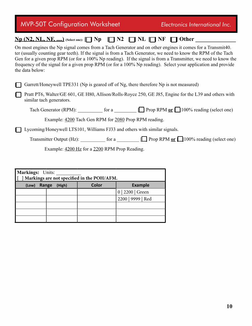
Np (N2, NL, NF, ....) (Select one): [ ] Np [ ] N2 [ ] NL [ ] NF [ ] Other ______________ On most engines the Np signal comes from a Tach Generator and on other engines it comes for a Transmit40.ter (usually counting gear teeth). If the signal is from a Tach Generator, we need to know the RPM of the Tach Gen for a given prop RPM (or for a 100% Np reading). If the signal is from a Transmitter, we need to know the frequency of the signal for a given prop RPM (or for a 100% Np reading). Select your application and provide the data below:
[ ] Garrett/Honeywell TPE331 (Np is geared off of Ng, there therefore Np is not measured)
[ ] Pratt PT6, Walter/GE 601, GE H80, Allison/Rolls-Royce 250, GE J85, Engine for the L39 and others with similar tach generators.
Tach Generator (RPM): __________ for a _________ [ ] Prop RPM or [ ]100% reading (select one)
Example: 4200 Tach Gen RPM for 2080 Prop RPM reading.
[ ] Lycoming/Honeywell LTS101, Williams FJ33 and others with similar signals.
Transmitter Output (Hz): __________ for a _________ [ ] Prop RPM or [ ]100% reading (select one)
Example: 4200 Hz for a 2200 RPM Prop Reading.
Markings: Units: __________ [ ] Markings are not specified in the POH/AFM.
(Low) Range (High) Color Example0 | 2200 | Green2200 | 9999 | Red
11
MVP-50T Configuration Worksheet Electronics International Inc.
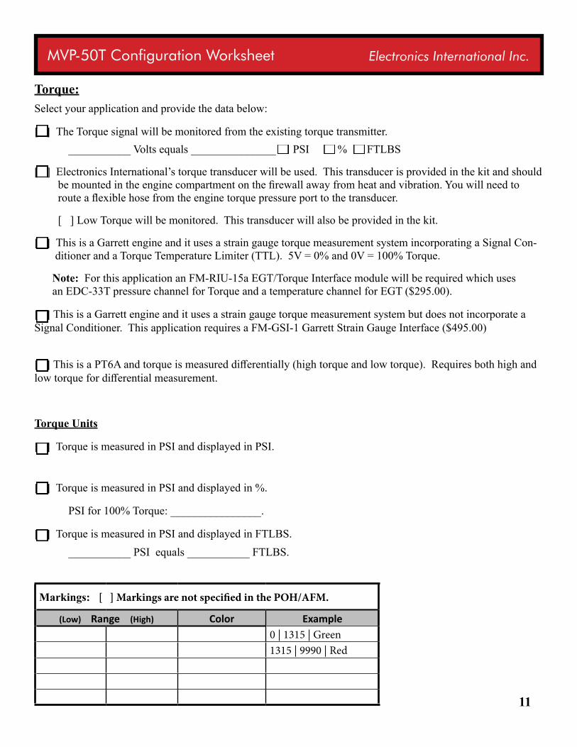
Torque:Select your application and provide the data below:
[ ] The Torque signal will be monitored from the existing torque transmitter. ___________ Volts equals _______________ PSI % FTLBS
[ ] Electronics International’s torque transducer will be used. This transducer is provided in the kit and should be mounted in the engine compartment on the firewall away from heat and vibration. You will need to route a flexible hose from the engine torque pressure port to the transducer.
[ ] Low Torque will be monitored. This transducer will also be provided in the kit.
[ ] This is a Garrett engine and it uses a strain gauge torque measurement system incorporating a Signal Con-ditioner and a Torque Temperature Limiter (TTL). 5V = 0% and 0V = 100% Torque.
Note: For this application an FM-RIU-15a EGT/Torque Interface module will be required which uses an EDC-33T pressure channel for Torque and a temperature channel for EGT ($295.00).
[ ] This is a Garrett engine and it uses a strain gauge torque measurement system but does not incorporate a Signal Conditioner. This application requires a FM-GSI-1 Garrett Strain Gauge Interface ($495.00)
[ ] This is a PT6A and torque is measured differentially (high torque and low torque). Requires both high and low torque for differential measurement. Torque Units
[ ] Torque is measured in PSI and displayed in PSI.
[ ] Torque is measured in PSI and displayed in %.
PSI for 100% Torque: ________________.
[ ] Torque is measured in PSI and displayed in FTLBS. ___________ PSI equals ___________ FTLBS.
Markings: [ ] Markings are not specified in the POH/AFM.
(Low) Range (High) Color Example0 | 1315 | Green1315 | 9990 | Red
12
MVP-50T Configuration Worksheet Electronics International Inc.
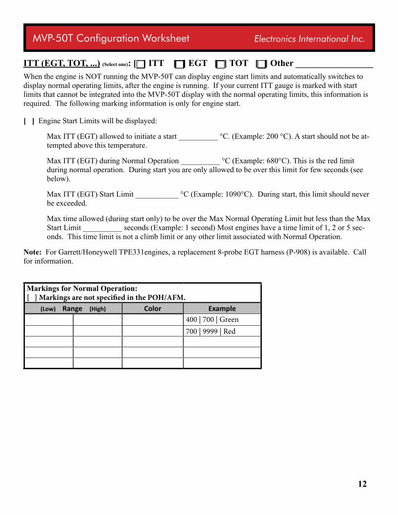
ITT (EGT, TOT, ...) (Select one): [ ] ITT [ ] EGT [ ] TOT [ ] Other _________________When the engine is NOT running the MVP-50T can display engine start limits and automatically switches to display normal operating limits, after the engine is running. If your current ITT gauge is marked with start limits that cannot be integrated into the MVP-50T display with the normal operating limits, this information is required. The following marking information is only for engine start.
[ ] Engine Start Limits will be displayed:
Max ITT (EGT) allowed to initiate a start __________ °C. (Example: 200 °C). A start should not be at-tempted above this temperature.
Max ITT (EGT) during Normal Operation __________ °C (Example: 680°C). This is the red limit during normal operation. During start you are only allowed to be over this limit for few seconds (see below).
Max ITT (EGT) Start Limit ___________ °C (Example: 1090°C). During start, this limit should never be exceeded.
Max time allowed (during start only) to be over the Max Normal Operating Limit but less than the Max Start Limit __________ seconds (Example: 1 second) Most engines have a time limit of 1, 2 or 5 sec-onds. This time limit is not a climb limit or any other limit associated with Normal Operation.
Note: For Garrett/Honeywell TPE331engines, a replacement 8-probe EGT harness (P-908) is available. Call for information.
Markings for Normal Operation: [ ] Markings are not specified in the POH/AFM.
(Low) Range (High) Color Example400 | 700 | Green700 | 9999 | Red
13
MVP-50T Configuration Worksheet Electronics International Inc.
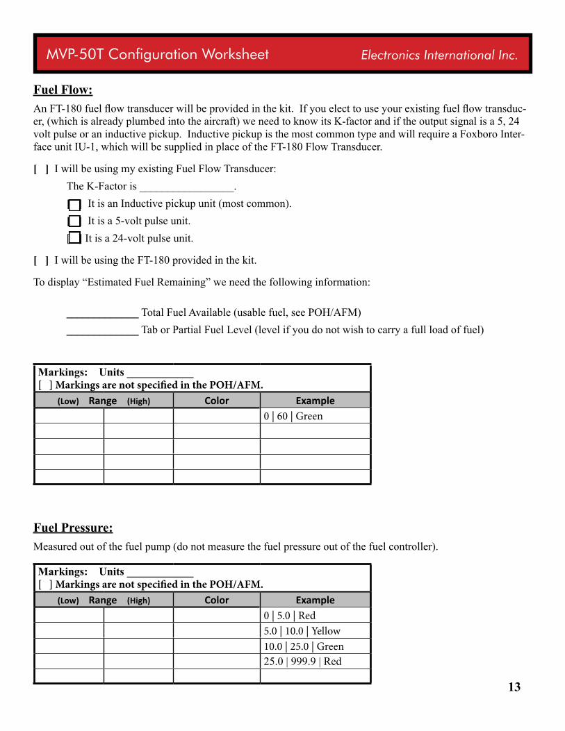
Fuel Flow:An FT-180 fuel flow transducer will be provided in the kit. If you elect to use your existing fuel flow transduc-er, (which is already plumbed into the aircraft) we need to know its K-factor and if the output signal is a 5, 24 volt pulse or an inductive pickup. Inductive pickup is the most common type and will require a Foxboro Inter-face unit IU-1, which will be supplied in place of the FT-180 Flow Transducer.
[ ] I will be using my existing Fuel Flow Transducer: The K-Factor is _________________. [ ] It is an Inductive pickup unit (most common). [ ] It is a 5-volt pulse unit. [ ] It is a 24-volt pulse unit.
[ ] I will be using the FT-180 provided in the kit.
To display “Estimated Fuel Remaining” we need the following information:
_____________ Total Fuel Available (usable fuel, see POH/AFM) _____________ Tab or Partial Fuel Level (level if you do not wish to carry a full load of fuel)
Markings: Units ____________ [ ] Markings are not specified in the POH/AFM.
(Low) Range (High) Color Example0 | 60 | Green
Fuel Pressure:Measured out of the fuel pump (do not measure the fuel pressure out of the fuel controller).
Markings: Units ____________ [ ] Markings are not specified in the POH/AFM.
(Low) Range (High) Color Example0 | 5.0 | Red5.0 | 10.0 | Yellow10.0 | 25.0 | Green25.0 | 999.9 | Red
14
MVP-50T Configuration Worksheet Electronics International Inc.
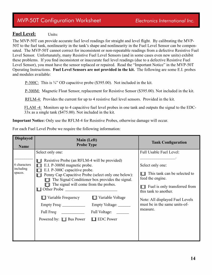
Fuel Level:The MVP-50T can provide accurate fuel level readings for straight and level flight. By calibrating the MVP-50T to the fuel tank, nonlinearity in the tank’s shape and nonlinearity in the Fuel Level Sensor can be compen-sated. The MVP-50T cannot correct for inconsistent or non-repeatable readings from a defective Resistive Fuel Level Sensor. Unfortunately, many Resistive Fuel Level Sensors (and in some cases even new units) exhibit these problems. If you find inconsistent or inaccurate fuel level readings (due to a defective Resistive Fuel Level Sensor), you must have the sensor replaced or repaired. Read the “Important Notice” in the MVP-50T Operating Instructions. Fuel Level Sensors are not provided in the kit. The following are some E.I. probes and modules available:
P-300C: This is ¾” OD capacitive probe ($395.00). Not included in the kit.
P-300M: Magnetic Float Sensor, replacement for Resistive Sensor ($395.00). Not included in the kit.
RFLM-4: Provides the current for up to 4 resistive fuel level sensors. Provided in the kit.
FLAM -4: Monitors up to 4 capacitive fuel level probes in one tank and outputs the signal to the EDC-33x as a single tank ($475.00). Not included in the kit.
Important Notice: Only use the RFLM-4 for Resistive Probes, otherwise damage will occur.
For each Fuel Level Probe we require the following information:
Displayed
NameMain (Left) Probe Type Tank Configuration
_________
6 characters including spaces.
Select only one:
[ ] Resistive Probe (an RFLM-4 will be provided) [ ] E.I. P-300M magnetic probe. [ ] E.I. P-300C capacitive probe. [ ] Penny Cap Capacitive Probe (select only one below): [ ] The Signal Conditioner box provides the signal. [ ] The signal will come from the probes. [ ] Other Probe _________________________
[ ] Variable Frequency [ ] Variable Voltage
Empty Freq: ___________ Empty Voltage: ______
Full Freq: ___________ Full Voltage: ______
Powered by: [ ] Bus Power [ ] EDC Power
Full Usable Fuel Level: _________________.
Select only one:
[ ] This tank can be selected to feed the engine.
[ ] Fuel is only transferred from this tank to another.
Note: All displayed Fuel Levels must be in the same units-of-measure.
Units:
15
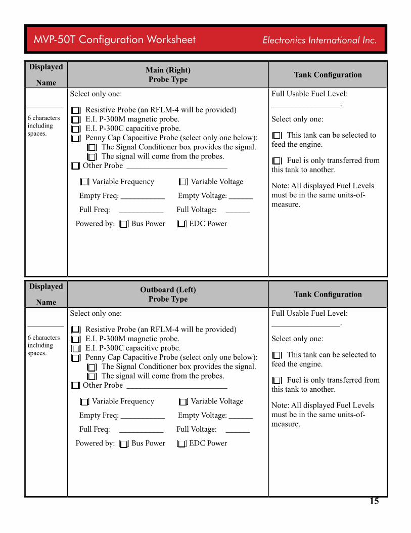
MVP-50T Configuration Worksheet Electronics International Inc.
Displayed
NameMain (Right) Probe Type Tank Configuration
_________
6 characters including spaces.
Select only one:
[ ] Resistive Probe (an RFLM-4 will be provided) [ ] E.I. P-300M magnetic probe. [ ] E.I. P-300C capacitive probe. [ ] Penny Cap Capacitive Probe (select only one below): [ ] The Signal Conditioner box provides the signal. [ ] The signal will come from the probes. [ ] Other Probe _________________________
[ ] Variable Frequency [ ] Variable Voltage
Empty Freq: ___________ Empty Voltage: ______
Full Freq: ___________ Full Voltage: ______
Powered by: [ ] Bus Power [ ] EDC Power
Full Usable Fuel Level: _________________.
Select only one:
[ ] This tank can be selected to feed the engine.
[ ] Fuel is only transferred from this tank to another.
Note: All displayed Fuel Levels must be in the same units-of-measure.
Displayed
NameOutboard (Left)
Probe Type Tank Configuration
_________
6 characters including spaces.
Select only one:
[ ] Resistive Probe (an RFLM-4 will be provided) [ ] E.I. P-300M magnetic probe. [ ] E.I. P-300C capacitive probe. [ ] Penny Cap Capacitive Probe (select only one below): [ ] The Signal Conditioner box provides the signal. [ ] The signal will come from the probes. [ ] Other Probe _________________________
[ ] Variable Frequency [ ] Variable Voltage
Empty Freq: ___________ Empty Voltage: ______
Full Freq: ___________ Full Voltage: ______
Powered by: [ ] Bus Power [ ] EDC Power
Full Usable Fuel Level: _________________.
Select only one:
[ ] This tank can be selected to feed the engine.
[ ] Fuel is only transferred from this tank to another.
Note: All displayed Fuel Levels must be in the same units-of-measure.
16
MVP-50T Configuration Worksheet Electronics International Inc.
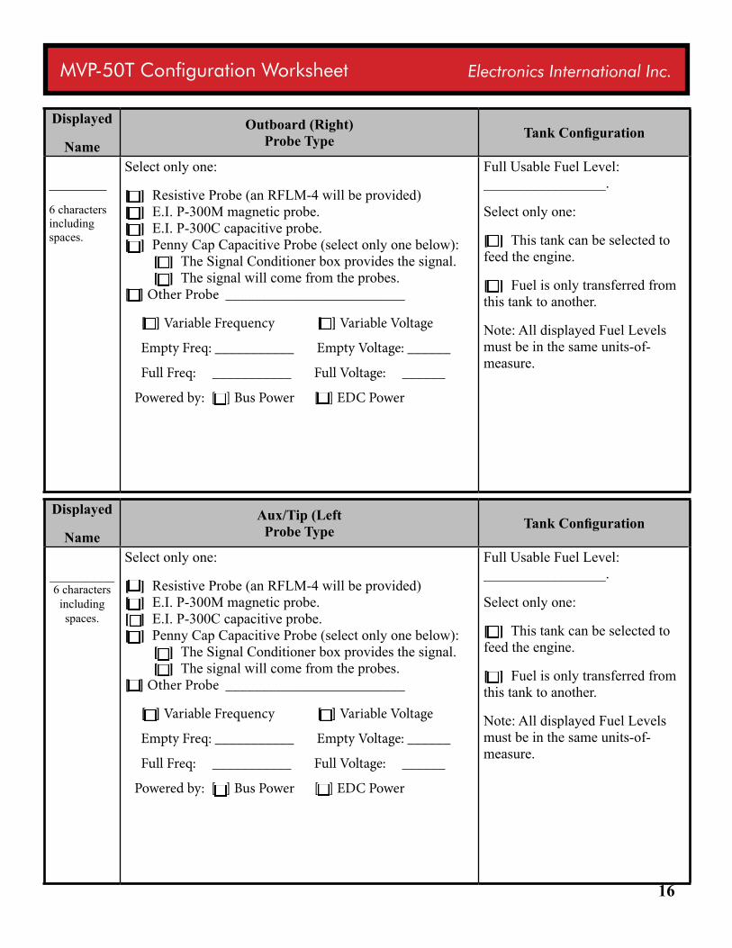
Displayed
NameOutboard (Right)
Probe Type Tank Configuration
________
6 characters including spaces.
Select only one:
[ ] Resistive Probe (an RFLM-4 will be provided) [ ] E.I. P-300M magnetic probe. [ ] E.I. P-300C capacitive probe. [ ] Penny Cap Capacitive Probe (select only one below): [ ] The Signal Conditioner box provides the signal. [ ] The signal will come from the probes. [ ] Other Probe _________________________
[ ] Variable Frequency [ ] Variable Voltage
Empty Freq: ___________ Empty Voltage: ______
Full Freq: ___________ Full Voltage: ______
Powered by: [ ] Bus Power [ ] EDC Power
Full Usable Fuel Level: _________________.
Select only one:
[ ] This tank can be selected to feed the engine.
[ ] Fuel is only transferred from this tank to another.
Note: All displayed Fuel Levels must be in the same units-of-measure.
Displayed
NameAux/Tip (Left
Probe Type Tank Configuration
_________6 characters
including spaces.
Select only one:
[ ] Resistive Probe (an RFLM-4 will be provided) [ ] E.I. P-300M magnetic probe. [ ] E.I. P-300C capacitive probe. [ ] Penny Cap Capacitive Probe (select only one below): [ ] The Signal Conditioner box provides the signal. [ ] The signal will come from the probes. [ ] Other Probe _________________________
[ ] Variable Frequency [ ] Variable Voltage
Empty Freq: ___________ Empty Voltage: ______
Full Freq: ___________ Full Voltage: ______
Powered by: [ ] Bus Power [ ] EDC Power
Full Usable Fuel Level: _________________.
Select only one:
[ ] This tank can be selected to feed the engine.
[ ] Fuel is only transferred from this tank to another.
Note: All displayed Fuel Levels must be in the same units-of-measure.
17
MVP-50T Configuration Worksheet Electronics International Inc.
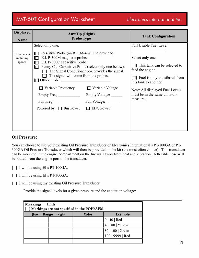
Displayed
NameAux/Tip (Right)
Probe Type Tank Configuration
_________6 characters
including spaces.
Select only one:
[ ] Resistive Probe (an RFLM-4 will be provided) [ ] E.I. P-300M magnetic probe. [ ] E.I. P-300C capacitive probe. [ ] Penny Cap Capacitive Probe (select only one below): [ ] The Signal Conditioner box provides the signal. [ ] The signal will come from the probes. [ ] Other Probe _________________________
[ ] Variable Frequency [ ] Variable Voltage
Empty Freq: ___________ Empty Voltage: ______
Full Freq: ___________ Full Voltage: ______
Powered by: [ ] Bus Power [ ] EDC Power
Full Usable Fuel Level: _________________.
Select only one:
[ ] This tank can be selected to feed the engine.
[ ] Fuel is only transferred from this tank to another.
Note: All displayed Fuel Levels must be in the same units-of-measure.
Oil Pressure:
You can choose to use your existing Oil Pressure Transducer or Electronics International’s PT-100GA or PT-300GA Oil Pressure Transducer which will then be provided in the kit (the most often choice). This transducer can be mounted in the engine compartment on the fire wall away from heat and vibration. A flexible hose will be routed from the engine port to the transducer. [ ] I will be using EI’s PT-100GA.
[ ] I will be using EI’s PT-300GA.
[ ] I will be using my existing Oil Pressure Transducer:
Provide the signal levels for a given pressure and the excitation voltage:
_________________________________________________________________________________.Markings: Units ____________ [ ] Markings are not specified in the POH/AFM.
(Low) Range (High) Color Example0 | 40 | Red40 | 80 | Yellow80 | 100 | Green100 | 9999 | Red
18
MVP-50T Configuration Worksheet Electronics International Inc.
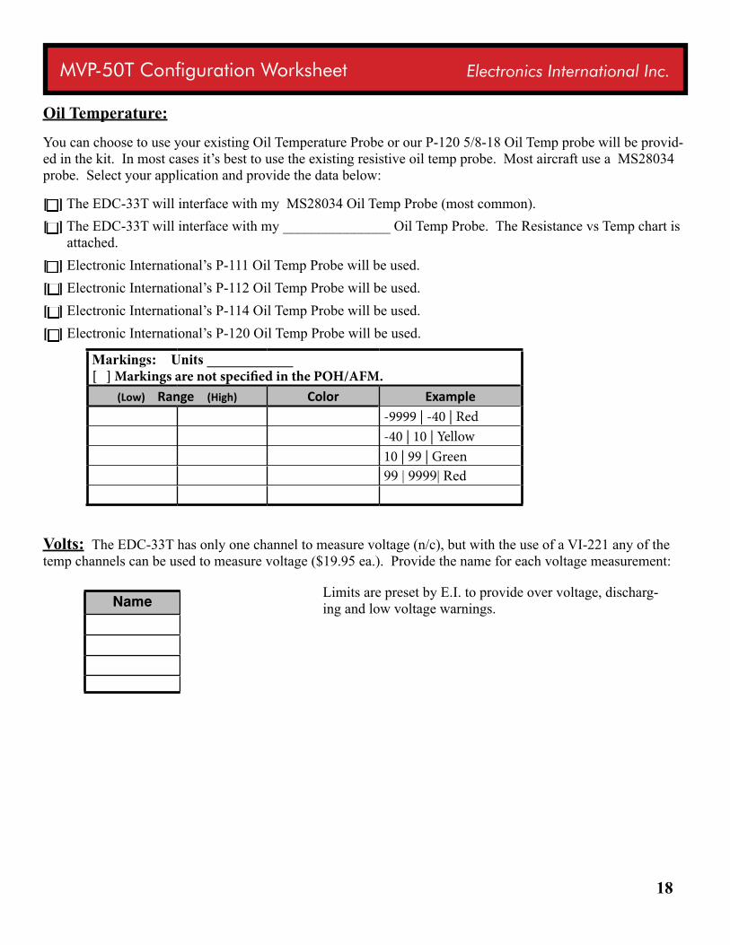
Oil Temperature:
You can choose to use your existing Oil Temperature Probe or our P-120 5/8-18 Oil Temp probe will be provid-ed in the kit. In most cases it’s best to use the existing resistive oil temp probe. Most aircraft use a MS28034 probe. Select your application and provide the data below:
[ ] The EDC-33T will interface with my MS28034 Oil Temp Probe (most common).[ ] The EDC-33T will interface with my _______________ Oil Temp Probe. The Resistance vs Temp chart is
attached.[ ] Electronic International’s P-111 Oil Temp Probe will be used.[ ] Electronic International’s P-112 Oil Temp Probe will be used.[ ] Electronic International’s P-114 Oil Temp Probe will be used.[ ] Electronic International’s P-120 Oil Temp Probe will be used.
Markings: Units ____________ [ ] Markings are not specified in the POH/AFM.
(Low) Range (High) Color Example-9999 | -40 | Red-40 | 10 | Yellow10 | 99 | Green99 | 9999| Red
Volts: The EDC-33T has only one channel to measure voltage (n/c), but with the use of a VI-221 any of the temp channels can be used to measure voltage ($19.95 ea.). Provide the name for each voltage measurement:
Name Loc EDCLimits are preset by E.I. to provide over voltage, discharg-ing and low voltage warnings.
19
MVP-50T Configuration Worksheet Electronics International Inc.
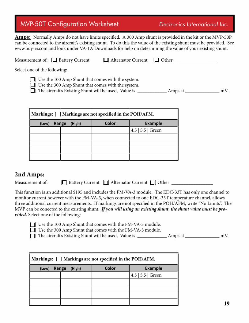
Amps: Normally Amps do not have limits specified. A 300 Amp shunt is provided in the kit or the MVP-50P can be connected to the aircraft’s existing shunt. To do this the value of the existing shunt must be provided. See www.buy-ei.com and look under VA-1A Downloads for help on determining the value of your existing shunt.
Measurement of: [ ] Battery Current [ ] Alternator Current [ ] Other __________________
Select one of the following:
[ ] Use the 100 Amp Shunt that comes with the system. [ ] Use the 300 Amp Shunt that comes with the system. [ ] The aircraft’s Existing Shunt will be used, Value is ____________ Amps at ______________ mV.
Markings: [ ] Markings are not specified in the POH/AFM.
(Low) Range (High) Color Example4.5 | 5.5 | Green
2nd Amps: Measurement of: [ ] Battery Current [ ] Alternator Current [ ] Other _________________ This function is an additional $195 and includes the FM-VA-3 module. The EDC-33T has only one channel to monitor current however with the FM-VA-3, when connected to one EDC-33T temperature channel, allows three additional current measurements. If markings are not specified in the POH/AFM, write “No Limits”. The MVP can be conected to the existing shunt. If you will using an existing shunt, the shunt value must be pro-vided. Select one of the following:
[ ] Use the 100 Amp Shunt that comes with the FM-VA-3 module. [ ] Use the 300 Amp Shunt that comes with the FM-VA-3 module. [ ] The aircraft’s Existing Shunt will be used, Value is ____________ Amps at ______________ mV.
Markings: [ ] Markings are not specified in the POH/AFM.
(Low) Range (High) Color Example4.5 | 5.5 | Green
20
MVP-50T Configuration Worksheet Electronics International Inc.
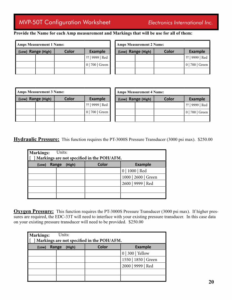
Provide the Name for each Amp measurement and Markings that will be use for all of them:
Hydraulic Pressure: This function requires the PT-3000S Pressure Transducer (3000 psi max). $250.00
Markings: [ ] Markings are not specified in the POH/AFM.
(Low) Range (High) Color Example0 | 1000 | Red1000 | 2600 | Green2600 | 9999 | Red
Oxygen Pressure: This function requires the PT-3000S Pressure Transducer (3000 psi max). If higher pres-sures are required, the EDC-33T will need to interface with your existing pressure transducer. In this case data on your existing pressure transducer will need to be provided. $250.00
Markings: [ ] Markings are not specified in the POH/AFM.
(Low) Range (High) Color Example0 | 300 | Yellow1550 | 1850 | Green2000 | 9999 | Red
Amps Measurement 1 Name: (Low) Range (High) Color Example
?? | 9999 | Red
0 | 700 | Green
Units:
Units:
Amps Measurement 2 Name: (Low) Range (High) Color Example
?? | 9999 | Red
0 | 700 | Green
Amps Measurement 3 Name: (Low) Range (High) Color Example
?? | 9999 | Red
0 | 700 | Green
Amps Measurement 4 Name: (Low) Range (High) Color Example
?? | 9999 | Red
0 | 700 | Green
21
MVP-50T Configuration Worksheet Electronics International Inc.
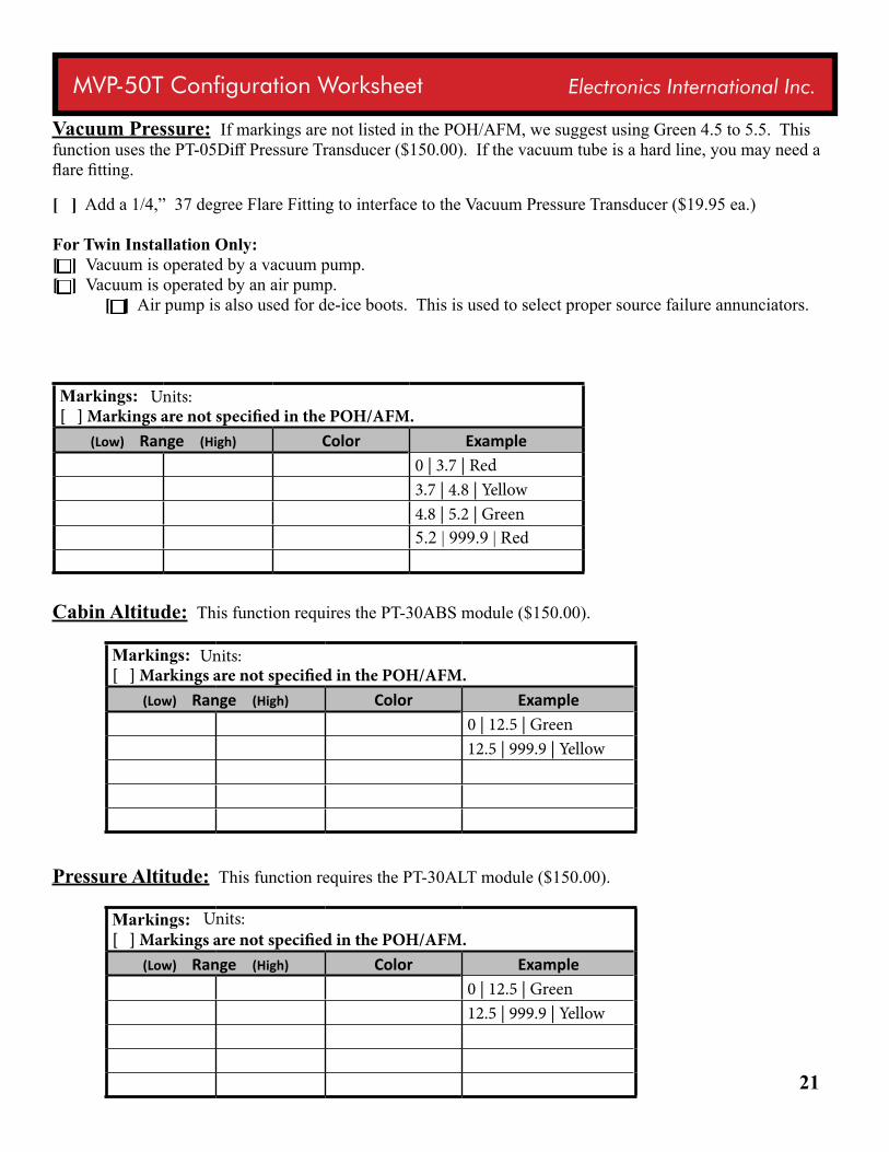
Vacuum Pressure: If markings are not listed in the POH/AFM, we suggest using Green 4.5 to 5.5. This function uses the PT-05Diff Pressure Transducer ($150.00). If the vacuum tube is a hard line, you may need a flare fitting.
[ ] Add a 1/4,” 37 degree Flare Fitting to interface to the Vacuum Pressure Transducer ($19.95 ea.) For Twin Installation Only: [ ] Vacuum is operated by a vacuum pump. [ ] Vacuum is operated by an air pump. [ ] Air pump is also used for de-ice boots. This is used to select proper source failure annunciators.
Markings: [ ] Markings are not specified in the POH/AFM.
(Low) Range (High) Color Example0 | 3.7 | Red3.7 | 4.8 | Yellow4.8 | 5.2 | Green5.2 | 999.9 | Red
Cabin Altitude: This function requires the PT-30ABS module ($150.00).
Markings: [ ] Markings are not specified in the POH/AFM.
(Low) Range (High) Color Example0 | 12.5 | Green12.5 | 999.9 | Yellow
Pressure Altitude: This function requires the PT-30ALT module ($150.00).
Markings: [ ] Markings are not specified in the POH/AFM.
(Low) Range (High) Color Example0 | 12.5 | Green12.5 | 999.9 | Yellow
Units:
Units:
Units:
22
MVP-50T Configuration Worksheet Electronics International Inc.
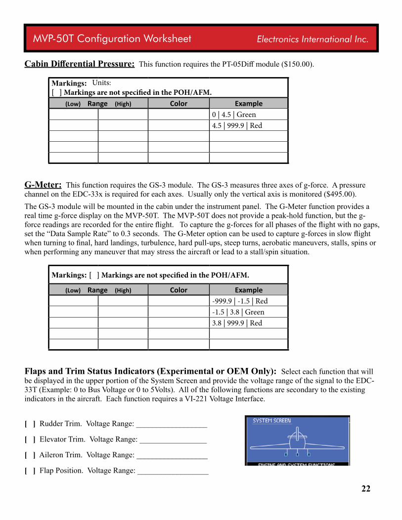
Cabin Differential Pressure: This function requires the PT-05Diff module ($150.00).
Markings: [ ] Markings are not specified in the POH/AFM.
(Low) Range (High) Color Example0 | 4.5 | Green4.5 | 999.9 | Red
G-Meter: This function requires the GS-3 module. The GS-3 measures three axes of g-force. A pressure channel on the EDC-33x is required for each axes. Usually only the vertical axis is monitored ($495.00). The GS-3 module will be mounted in the cabin under the instrument panel. The G-Meter function provides a real time g-force display on the MVP-50T. The MVP-50T does not provide a peak-hold function, but the g-force readings are recorded for the entire flight. To capture the g-forces for all phases of the flight with no gaps, set the “Data Sample Rate” to 0.3 seconds. The G-Meter option can be used to capture g-forces in slow flight when turning to final, hard landings, turbulence, hard pull-ups, steep turns, aerobatic maneuvers, stalls, spins or when performing any maneuver that may stress the aircraft or lead to a stall/spin situation.
Markings: [ ] Markings are not specified in the POH/AFM.
(Low) Range (High) Color Example-999.9 | -1.5 | Red-1.5 | 3.8 | Green3.8 | 999.9 | Red
Flaps and Trim Status Indicators (Experimental or OEM Only): Select each function that will be displayed in the upper portion of the System Screen and provide the voltage range of the signal to the EDC-33T (Example: 0 to Bus Voltage or 0 to 5Volts). All of the following functions are secondary to the existing indicators in the aircraft. Each function requires a VI-221 Voltage Interface.
[ ] Rudder Trim. Voltage Range: __________________
[ ] Elevator Trim. Voltage Range: _________________
[ ] Aileron Trim. Voltage Range: __________________
[ ] Flap Position. Voltage Range: __________________
Units:
23
MVP-50T Configuration Worksheet Electronics International Inc.
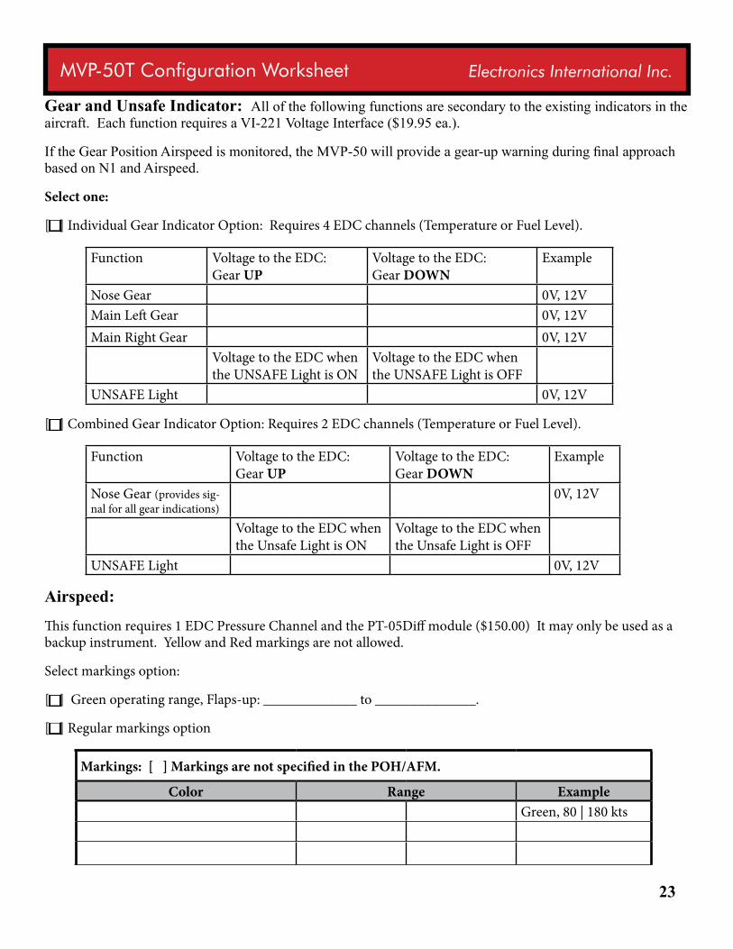
Gear and Unsafe Indicator: All of the following functions are secondary to the existing indicators in the aircraft. Each function requires a VI-221 Voltage Interface ($19.95 ea.).
If the Gear Position Airspeed is monitored, the MVP-50 will provide a gear-up warning during final approach based on N1 and Airspeed.
Select one:
[ ] Individual Gear Indicator Option: Requires 4 EDC channels (Temperature or Fuel Level).
Function Voltage to the EDC: Gear UP
Voltage to the EDC: Gear DOWN
Example
Nose Gear 0V, 12VMain Left Gear 0V, 12VMain Right Gear 0V, 12V
Voltage to the EDC when the UNSAFE Light is ON
Voltage to the EDC when the UNSAFE Light is OFF
UNSAFE Light 0V, 12V
[ ] Combined Gear Indicator Option: Requires 2 EDC channels (Temperature or Fuel Level).
Function Voltage to the EDC: Gear UP
Voltage to the EDC: Gear DOWN
Example
Nose Gear (provides sig-nal for all gear indications)
0V, 12V
Voltage to the EDC when the Unsafe Light is ON
Voltage to the EDC when the Unsafe Light is OFF
UNSAFE Light 0V, 12V
Airspeed:
This function requires 1 EDC Pressure Channel and the PT-05Diff module ($150.00) It may only be used as a backup instrument. Yellow and Red markings are not allowed.
Select markings option:
[ ] Green operating range, Flaps-up: _____________ to ______________.
[ ] Regular markings option
Markings: [ ] Markings are not specified in the POH/AFM.
Color Range ExampleGreen, 80 | 180 kts
24
MVP-50T Configuration Worksheet Electronics International Inc.
RTDO: This feature provides real time data out of a RS232 port on the MVP-50T ($667.00)
[ ] Add RTDO to the kit.
Any Other Function: Almost any function can be monitored by the EDC-33T and scaled by the MVP-50T to provide a digital and analog display of its value or to drive an annunciator. Provide data below:
25
MVP-50T Configuration Worksheet Electronics International Inc.
Appendix A:
EDC-33T Overview
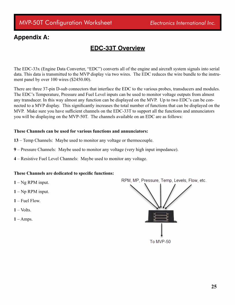
The EDC-33x (Engine Data Converter, “EDC”) converts all of the engine and aircraft system signals into serial data. This data is transmitted to the MVP display via two wires. The EDC reduces the wire bundle to the instru-ment panel by over 100 wires ($2450.00).
There are three 37-pin D-sub connectors that interface the EDC to the various probes, transducers and modules. The EDC’s Temperature, Pressure and Fuel Level inputs can be used to monitor voltage outputs from almost any transducer. In this way almost any function can be displayed on the MVP. Up to two EDC’s can be con-nected to a MVP display. This significantly increases the total number of functions that can be displayed on the MVP. Make sure you have sufficient channels on the EDC-33T to support all the functions and annunciators you will be displaying on the MVP-50T. The channels available on an EDC are as follows:
These Channels can be used for various functions and annunciators:
13 – Temp Channels: Maybe used to monitor any voltage or thermocouple.
9 – Pressure Channels: Maybe used to monitor any voltage (very high input impedance).
4 – Resistive Fuel Level Channels: Maybe used to monitor any voltage.
These Channels are dedicated to specific functions:
1 – Ng RPM input.
1 – Np RPM input.
1 – Fuel Flow.
1 – Volts.
1 – Amps.
26
MVP-50T Configuration Worksheet Electronics International Inc.
* Be sure you have ordered the hardware to support all the functions listed in this document.
* Check that all range and configuration information is complete and accurate.
I (the undersigned) have entered and verified all the limits, markings and aircraft configurations listed in this worksheet to be correct and taken from the information in the aircraft’s POH/ AFM which includes any changes mandated by any AD’s, Supplements and STC’s. When necessary, I have checked with my FAA certified me-chanic to insure all of the data listed above is correct.
I understand there is important safety information in the Installation and Operating Instructions that must be read before installing the MVP-50T system and flying the aircraft.
Completed by: [ ] Owner [ ] Pilot [ ] Technician [ ] Other _______________
-------------------------------------- ---------------------------------------- ------------------------ Completed By Printed Name Completed By Signature Date
FAILURE TO SIGN THIS DOCUMENT WILL RESULT IN AN INCOMPLETE FORM AND WILL DELAY YOUR ORDER
Hand signature or Encrypted Digital signature required.


![DP-50/DP-50T Digital Ultrasonic Diagnostic Imaging System ... · DP-50/DP-50T Digital Ultrasonic Diagnostic Imaging System Operator’s Manual [Advanced Volume]](https://img.pdfslide.us/doc/110x75/6035e6674bf1e56ba2231737/dp-50dp-50t-digital-ultrasonic-diagnostic-imaging-system-dp-50dp-50t-digital.jpg)