Embed Size (px)
Citation preview
MV protection relay
Installation assistance guide
Sepam ranges
Series 20
Series 40
Series 80
Sepam 2000
© Copyright Schneider Electric Industries SAS, 2005 51312779F0 A2 1/60
Sepam protection relay installation assistance guide
Contents Aims of the guide .................................................................................................................................. 3 Reference documents ........................................................................................................................... 3 Part I: Generic installation rules .......................................................................................................... 4
Classification of signals according to level of disturbance or sensitivity.................................................4 Basic installation rules ............................................................................................................................4
Part II: MV cubicle prerequisites.......................................................................................................... 8 Equipotential bonding of the installation .................................................................................................8 Equipotential bonding of metallic enclosures .........................................................................................8 Reference for support frames in the LV compartment............................................................................9 Availability of an earthing terminal in the LV compartment.....................................................................9 LV compartment protection and filtering devices....................................................................................9 MV cubicle maintenance.......................................................................................................................10 MV current transformers (1A or 5A CTs) ..............................................................................................11 MV voltage transformers (VTs).............................................................................................................11
Part III: Specific installation rules for Sepam and its accessories................................................. 12 Type of electrical connections to Sepam..............................................................................................12 Sepam cabling management ................................................................................................................13 Connection of Sepam and its accessories to the local ground.............................................................14
Connection of Sepam to the local ground.........................................................................................14 Connection of Sepam accessories to the local ground.....................................................................16
Sepam line current inputs (I1 to I3 or I'1 to I'3) .....................................................................................17 Sepam residual current input (I0 or I'0) ................................................................................................18
CSH120 or CSH200 core balance CTs.............................................................................................18 CSH30 interposing ring CT ...............................................................................................................20 ACE990 interface ..............................................................................................................................22
Sepam voltage inputs (U21, U32, U13, V0, V1, V2, V3) ......................................................................23 Sepam power supply source ................................................................................................................25
Sepam supply source functions ........................................................................................................25 Electrical characteristics of the Sepam supply source......................................................................25 Cabling ..............................................................................................................................................25 Installation of the Sepam supply source ...........................................................................................26 LV compartment supply by an AC power system .............................................................................27 LV compartment supply by a DC power system ...............................................................................32 Sepam power supply and logic input/output power supply ...............................................................35
Sepam's logic inputs (I1 to Ix or Ix1 to Ixx) ...........................................................................................36 Types of Sepam logic inputs .............................................................................................................36 Cabling ..............................................................................................................................................37 Logic input power supply source.......................................................................................................37 Sepam logic input cabling configurations..........................................................................................37 Supply source dedicated to insulated logic inputs ............................................................................42
Sepam logic outputs (O1 to O4, Ox1 to Ox4) .......................................................................................44 Type of Sepam logic outputs.............................................................................................................44 Cabling ..............................................................................................................................................44 Inductive load overvoltage limitiation devices ...................................................................................46
MET148-2 temperature sensor (RTD) module .....................................................................................47 MSA141 analog output module ............................................................................................................49 RS 485 communication network ...........................................................................................................51
Main communication accessories .....................................................................................................51 Line-end impedance matching and polarization resistors.................................................................52 Examples of installation.....................................................................................................................52
Annex 1: Logical connections for "Logic discrimination".............................................................. 57 Annex 2: Glossary ............................................................................................................................... 59
Copyright Schneider Electric Industries SAS, 2005 51312779F0 A2 2/60
Sepam protection relay installation assistance guide Aims of the guide The aim of this guide is to indicate the appropriate installation rules for the Sepam range of protection relays. These installation rules contribute to guaranteeing the correct operation and performance levels of Sepam relays in Medium Voltage cubicles. This guide does not take anything away from the Sepam technical documents. It is aimed at providing further explanations and additional information on the installation rules that already exist for Sepam, in particular regarding electromagnetic phenomena. The guide is intended for everyone in charge of installing Sepam range protection relays: OEMs, project managers and customer technical support. The contents of the guide may be used in the implementation of Sepam in new electrical installations, or when retrofit operations are carried out in existing installations. The guide mainly deals with the implementation of Sepam relays in Medium Voltage cubicles. The installation rules mentioned are independent of the type of Medium Voltage cubicle. The implementation of Sepam in another type of switchgear assembly may involve particular installation rules. The guide concisely addresses the different key points of installation, with the intent of focusing on practical use. Numerous illustrations taken from Sepam user manuals are included for that purpose. The guide mainly concerns the following ranges of Sepam protection relays: - Series 20 - Series 40 - Series 80 - Sepam 2000. The guide is organized in three separate parts: - Part I : Generic installation rules - Part II : MV cubicle prerequisites - Part III : Specific installation rules for Sepam and its accessories.
All installation rules that are not stipulated in the Sepam user manuals or in this guide are to be prohibited. Reference documents
Reference Title of document PCRED301005EN2 Sepam Series 20: User manual PCRED301006EN/3 Sepam Series 40: User manual SEPED303005EN/2 Sepam Series 80: Catalogue 3140750F-F Sepam 2000 S25, S26 and S35, S36: Installation, use, commissioning, general characteristics DBTP542en Schneider "Technical guide 2000 – Modbus network"
Copyright Schneider Electric Industries SAS, 2005 51312779F0 A2 3/60
Sepam protection relay installation assistance guide
Part I: Generic installation rules Classification of signals according to level of disturbance or sensitivity All electrical cables contained in installations may be associated with the groups of signals defined in the table below:
Group Disturbing capacity Sensitivity level Examples
Group 1 ++ - Power circuits in general - Welding machine power supply - PEN and PE electrical conductors
Group 2 + - Control circuits including inductive loads (relays, contactors, etc.)
Group 3 + - Communication circuits
Group 4 ++ - Analog measurement circuits (RTDs,
sensors, etc.)
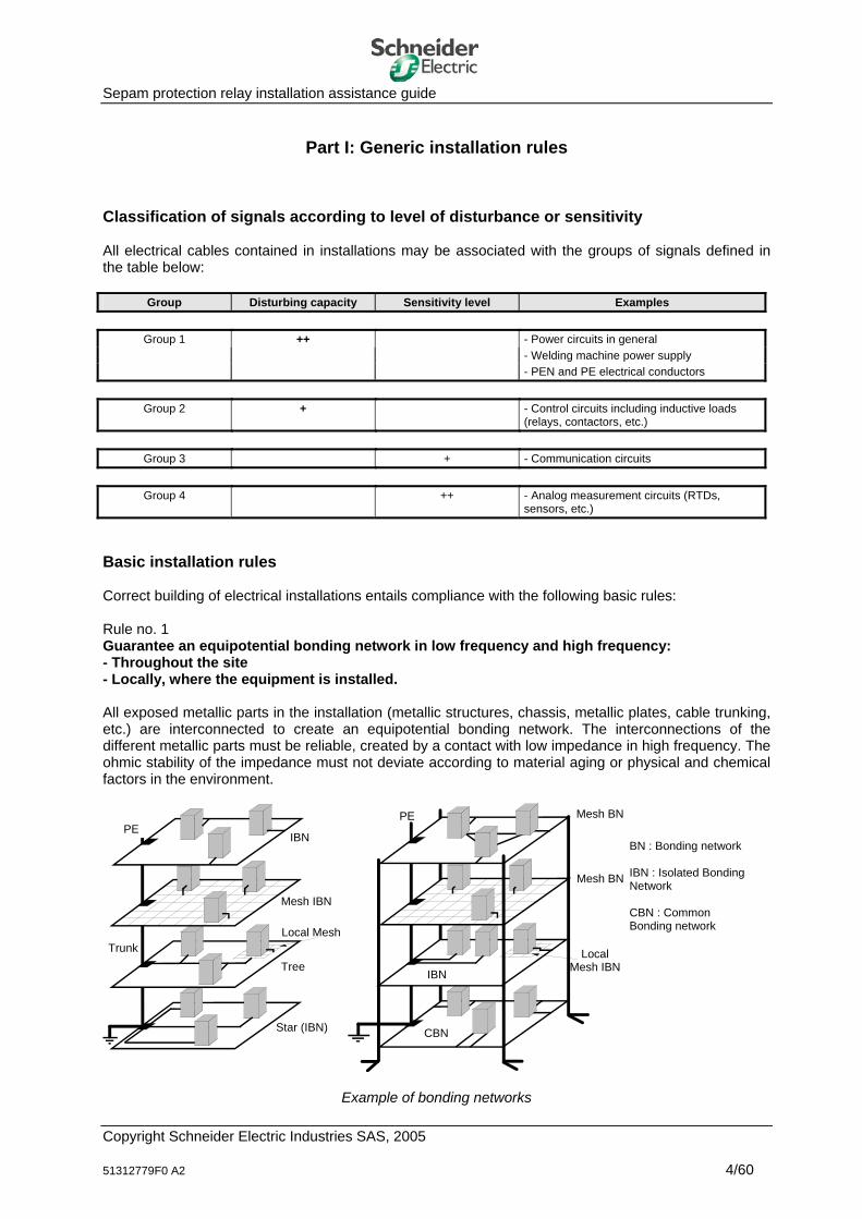
Basic installation rules Correct building of electrical installations entails compliance with the following basic rules: Rule no. 1 Guarantee an equipotential bonding network in low frequency and high frequency: - Throughout the site - Locally, where the equipment is installed. All exposed metallic parts in the installation (metallic structures, chassis, metallic plates, cable trunking, etc.) are interconnected to create an equipotential bonding network. The interconnections of the different metallic parts must be reliable, created by a contact with low impedance in high frequency. The ohmic stability of the impedance must not deviate according to material aging or physical and chemical factors in the environment.
Mesh BN
Local Mesh IBN
PE Mesh BN
CBN
IBN
Mesh IBN
Tree
Star (IBN)
Trunk
IBN
Local Mesh
PE
Example of bonding networks
Copyright Schneider Electric Industries SAS, 2005 51312779F0 A2
BN : Bonding network IBN : Isolated Bonding Network CBN : Common Bonding network
4/60

Sepam protection relay installation assistance guide
Rule no. 2 Cables in groups (1-2) are highly disturbing. It is essential for them to be separated from cables in groups (3-4) which are reputed to be sensitive. These signal groups are never conveyed in the same cable or in the same conductor. Incompatible signals ⇒ Different cables & bundles
differentiate the groups⇒
NO! YES!
Power + analog
Digital + relaying
Power + relaying
Digital+ analog
Power connections Digital connections
Analog connectionsRelayed I/O connections
Shielding screens
NO! YES!
Analog connectionsDigital connections
Rule no. 3 Minimize the length of cables running in parallel when they convey different signal groups, in particular between cables belonging to groups (1-2) and groups (3-4). Rule no. 4 Increase the distance between cables conveying different signal groups, in particular between cables belonging to groups (1-2) et (3-4). As a general rule, a distance of 10 cm is sufficient between the cable bundles arranged flat on a plate (in common mode and differential mode). If there is enough space, a distance of 30 cm between them is preferable.
The use of shielded cables allows cables belonging to different signal groups to cohabit. Rule no. 5 Minimize ground loop areas. A ground loop results from the area between an active conductor and the ground. Ground loops are often used unintentionally (lack of mastery of cabling, in particular). When the loop is subjected to an
Copyright Schneider Electric Industries SAS, 2005 51312779F0 A2 5/60
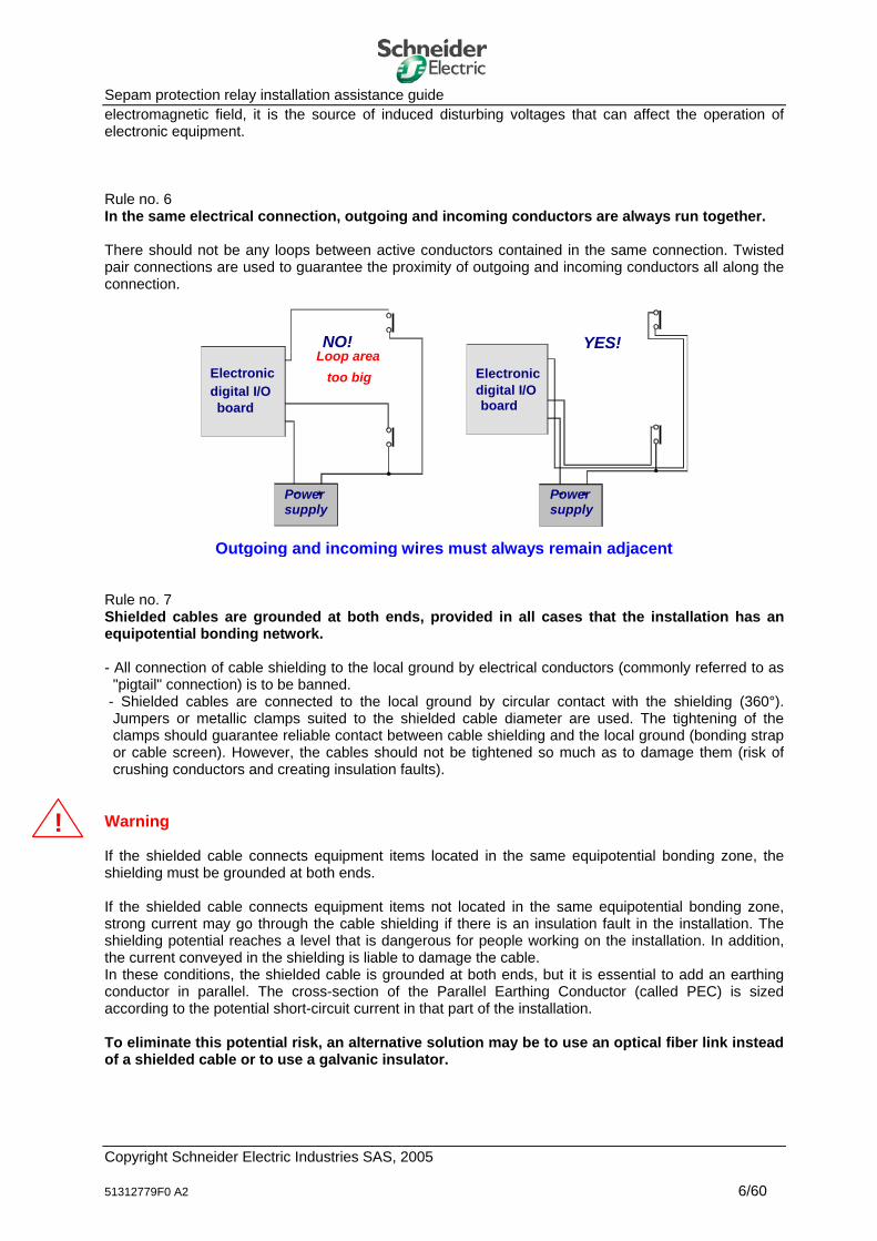
Sepam protection relay installation assistance guide electromagnetic field, it is the source of induced disturbing voltages that can affect the operation of electronic equipment. Rule no. 6 In the same electrical connection, outgoing and incoming conductors are always run together. There should not be any loops between active conductors contained in the same connection. Twisted pair connections are used to guarantee the proximity of outgoing and incoming conductors all along the connection.
Powersupply
Powersupply
Loop areatoo big Electronic
digital I/Oboard
Electronicdigital I/Oboard
NO! YES!
Outgoing and incoming wires must always remain adjacent Rule no. 7 Shielded cables are grounded at both ends, provided in all cases that the installation has an equipotential bonding network. - All connection of cable shielding to the local ground by electrical conductors (commonly referred to as
"pigtail" connection) is to be banned. - Shielded cables are connected to the local ground by circular contact with the shielding (360°).
Jumpers or metallic clamps suited to the shielded cable diameter are used. The tightening of the clamps should guarantee reliable contact between cable shielding and the local ground (bonding strap or cable screen). However, the cables should not be tightened so much as to damage them (risk of crushing conductors and creating insulation faults).
! Warning If the shielded cable connects equipment items located in the same equipotential bonding zone, the shielding must be grounded at both ends. If the shielded cable connects equipment items not located in the same equipotential bonding zone, strong current may go through the cable shielding if there is an insulation fault in the installation. The shielding potential reaches a level that is dangerous for people working on the installation. In addition, the current conveyed in the shielding is liable to damage the cable. In these conditions, the shielded cable is grounded at both ends, but it is essential to add an earthing conductor in parallel. The cross-section of the Parallel Earthing Conductor (called PEC) is sized according to the potential short-circuit current in that part of the installation. To eliminate this potential risk, an alternative solution may be to use an optical fiber link instead of a shielded cable or to use a galvanic insulator.
Copyright Schneider Electric Industries SAS, 2005 51312779F0 A2 6/60
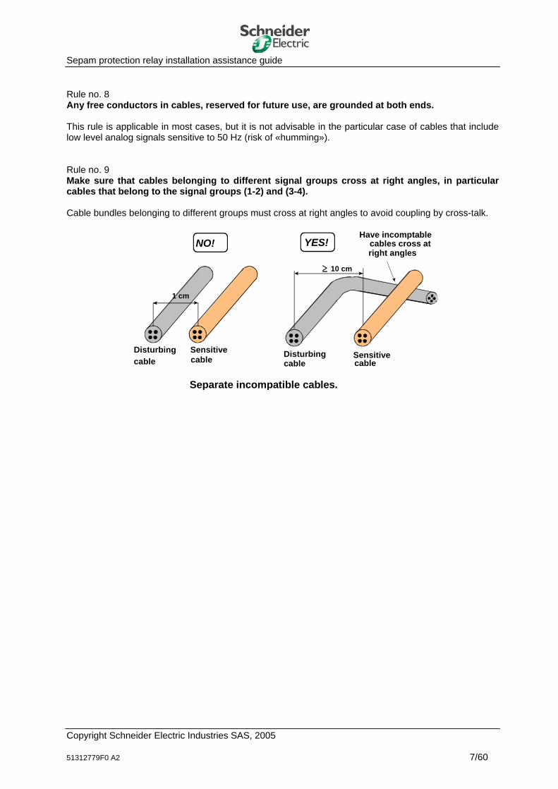
Sepam protection relay installation assistance guide Rule no. 8 Any free conductors in cables, reserved for future use, are grounded at both ends. This rule is applicable in most cases, but it is not advisable in the particular case of cables that include low level analog signals sensitive to 50 Hz (risk of «humming»). Rule no. 9 Make sure that cables belonging to different signal groups cross at right angles, in particular cables that belong to the signal groups (1-2) and (3-4). Cable bundles belonging to different groups must cross at right angles to avoid coupling by cross-talk.
Separate incompatible cables.
Have incomptablecables cross atright angles
Sensitivecable
Disturbingcable
Sensitivecable
Disturbingcable
NO! YES!
10 cm
1 cm
Copyright Schneider Electric Industries SAS, 2005 51312779F0 A2 7/60
Sepam protection relay installation assistance guide
Part II: MV cubicle prerequisites Equipotential bonding of the installation The equipotential bonding of electrical installations fulfills the following objectives: - Guarantee the safety of people and equipment
The different metallic components of the installation are interconnected and connected to the protective earth.
- Limit the appearance of potential differences between exposed metallic parts of installations. A
potential difference between exposed metallic parts, especially in high frequency, has an adverse effect on the operation of electronic equipment.
- Benefit from the effects of natural shielding provided by metallic structures
Many metallic structures are available in installations. They accompany the installation's electrical cables and their role is to limit the area of common mode loops. The use of the installation's metal structures does not entail any additional cost.
Equipotential bonding of metallic enclosures We will focus in this chapter on the equipotential bonding of metallic enclosures. The Medium Voltage cubicles, designed to include Sepam protection relays, generally comprise two separate compartments, the Medium Voltage (MV) compartment and the Low Voltage (LV) compartment: - The MV compartment houses the actual Medium Voltage switching device (generally a circuit breaker
or contactor) and the associated Medium Voltage components (CT current transformers, VT voltage transformers, etc.)
- The LV compartment contains all of the Low Voltage components, including Sepam and its accessories. Medium Voltage cubicles consist of a metallic enclosure, which should have high, well-controlled overall equipotential bonding. Electrical contact between the different metallic panels should be, if possible, via contact surfaces that have no paint, varnish or any insulating material on them. If this is not the case, the use of spring washers is strongly recommended, to penetrate the coat of paint on the MV compartment and guarantee reliable electrical contact. MV cubicles should be equipped with a main earthing terminal, comprising a bare copper bar with a rectangular cross-section. The main earthing terminal is used to connect the installation's protective earth (PE) protection cable. It is generally used as the potential reference for the MV current transformers (CTs) or MV voltage transformers (VTs). The LV compartment consists of a metallic receptacle, generally located above or beside the MV compartment. The purpose of the physical separation between the MV and LV compartments is to partition the LV compartment. This separation is essential to minimize the propagation of disturbances caused by MV switchgear operations toward the LV compartment. Such disturbances are mainly high frequency radiated electromagnetic interference. Equipontential bonding serves a true purpose in the LV compartment. Equipotential bonding is also guaranteed between the MV and LV compartment enclosures.
Copyright Schneider Electric Industries SAS, 2005 51312779F0 A2 8/60

Sepam protection relay installation assistance guide The doors of the MV and LV compartments contribute to reducing electromagnetic interference in the compartments (cubicle shielded attenuation). The presence of door hinges is not sufficient to guarantee equipotential bonding of the door and the compartment. The hinges are generally insufficient to guarantee the safety of people in the event of insulating faults occurring on equipment housed in one of the compartments. The doors of MV and LV compartments should be connected to the metallic structure at two points, preferably at the top and bottom of the door. Two tinned copper straps (or two electrical conductors that are as short as possible) should be used to interconnect the door and the compartment for that purpose. Since the compartment doors contribute to the EMC performance of the compartments, it goes without saying that the doors should be kept closed during operating phases. Openings and vents in the metallic door of the LV compartment should be avoided when possible or else be limited to the bare minimum. A metallic compartment, designed to house the MV power cables, may also be added to the MV cubicle. The concept of equipotential bonding applies to this cable compartment as well. Reference for support frames in the LV compartment LV compartments are generally equipped with DIN rails or metallic grids, designed to support Sepam accessories or optional modules. In order to achieve optimal equipotential bonding, electrical continuity must be controlled between the DIN rails or metallic grids and the LV compartment. In the particular case of DIN rails, at least one sure contact point must be provided at each end of the DIN rail. Availability of an earthing terminal in the LV compartment The LV compartment may also be equipped with an earthing terminal. Sure electrical continuity is required between the earthing terminal and the compartment's metal enclosure and the electrical resistance must be less than or equal to 10 mΩ at all points. The main purpose of having an earthing terminal in the LV compartment, in particular close to Sepam, is that it may be used as an effective reference for the cable shielding: - Analog signal cables connected to the MV core balance CT - Communication network cables, etc. When there is an earthing terminal, the following operations may be carried out: - Connect the shielded cables to ground as of the point at which they enter the LV compartment - Connect the shielded cables to ground by a circular (360°) contact using a conductive metallic clamp. LV compartment protection and filtering devices It should be possible to include protection and filtering devices in the LV compartment, in particular on the electronic equipment supply lines. The use of such devices may be necessary in highly disturbed electromagnetic environments. Protection and filtering devices include the following components: - Isolation transformer - Surge arrester - EMC filter.
Copyright Schneider Electric Industries SAS, 2005 51312779F0 A2 9/60

Sepam protection relay installation assistance guide MV cubicle maintenance Minimum maintenance of the MV cubicle is recommended to check the equipotential bonding. The maintenance operation may be limited to a visual inspection (once a year, for example). It consists of check that different metallic components of the cubicle are interconnected and tightened and that there is no corrosion (in particular in the presence of humidity or chemical factors favorable to oxidation). The maintenance operation is also an opportunity to check the tightening of the electrical conductors connected to the different equipment items, in both the MV and LV compartments. It is especially advisable in environments with major mechanical vibration constraints (e.g. monitoring and control of a high power asynchronous motor located near the MV cubicle). During the maintenance operation, any surge arresters present in the electrical installation (particularly any located in the LV compartment) should be checked. This operation may be limited to a visual inspection of the surge arrester operating indicator, for example.
Copyright Schneider Electric Industries SAS, 2005 51312779F0 A2 10/60
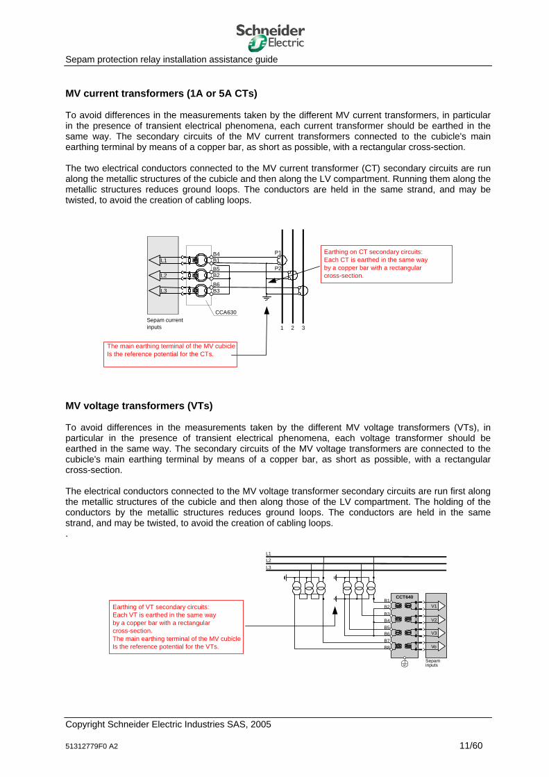
Sepam protection relay installation assistance guide MV current transformers (1A or 5A CTs) To avoid differences in the measurements taken by the different MV current transformers, in particular in the presence of transient electrical phenomena, each current transformer should be earthed in the same way. The secondary circuits of the MV current transformers connected to the cubicle's main earthing terminal by means of a copper bar, as short as possible, with a rectangular cross-section. The two electrical conductors connected to the MV current transformer (CT) secondary circuits are run along the metallic structures of the cubicle and then along the LV compartment. Running them along the metallic structures reduces ground loops. The conductors are held in the same strand, and may be twisted, to avoid the creation of cabling loops.
EM
L1
L2
L3
P1
P2
B4B1B5B2B6B3
CCA630
1 2 3
The main earthing terminal of the MV cubicleIs the reference potential for the CTs.
Earthing on CT secondary circuits:Each CT is earthed in the same wayby a copper bar with a rectangularcross-section.
Sepam currentinputs
MV voltage transformers (VTs) To avoid differences in the measurements taken by the different MV voltage transformers (VTs), in particular in the presence of transient electrical phenomena, each voltage transformer should be earthed in the same way. The secondary circuits of the MV voltage transformers are connected to the cubicle's main earthing terminal by means of a copper bar, as short as possible, with a rectangular cross-section. The electrical conductors connected to the MV voltage transformer secondary circuits are run first along the metallic structures of the cubicle and then along those of the LV compartment. The holding of the conductors by the metallic structures reduces ground loops. The conductors are held in the same strand, and may be twisted, to avoid the creation of cabling loops. .
L1L2L3
B4B5B6B7B8
B3
B1B2
CCT640
V1
V2
V3
Vo
Sepaminputs
Earthing of VT secondary circuits:Each VT is earthed in the same wayby a copper bar with a rectangularcross-section.The main earthing terminal of the MV cubicleIs the reference potential for the VTs.
Copyright Schneider Electric Industries SAS, 2005 51312779F0 A2 11/60
Sepam protection relay installation assistance guide
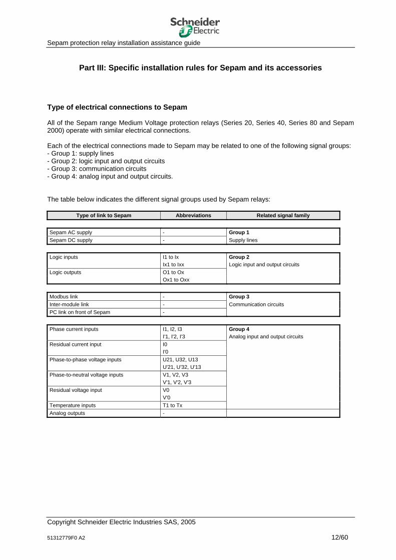
Part III: Specific installation rules for Sepam and its accessories Type of electrical connections to Sepam All of the Sepam range Medium Voltage protection relays (Series 20, Series 40, Series 80 and Sepam 2000) operate with similar electrical connections. Each of the electrical connections made to Sepam may be related to one of the following signal groups: - Group 1: supply lines - Group 2: logic input and output circuits - Group 3: communication circuits - Group 4: analog input and output circuits. The table below indicates the different signal groups used by Sepam relays:
Type of link to Sepam Abbreviations Related signal family Sepam AC supply - Group 1 Sepam DC supply - Supply lines Logic inputs I1 to Ix Group 2 Ix1 to Ixx Logic input and output circuits Logic outputs O1 to Ox Ox1 to Oxx Modbus link - Group 3 Inter-module link - Communication circuits PC link on front of Sepam - Phase current inputs I1, I2, I3 Group 4 I'1, I'2, I'3 Analog input and output circuits Residual current input I0 I'0 Phase-to-phase voltage inputs U21, U32, U13 U'21, U'32, U'13 Phase-to-neutral voltage inputs V1, V2, V3 V'1, V'2, V'3 Residual voltage input V0 V'0 Temperature inputs T1 to Tx Analog outputs -
Copyright Schneider Electric Industries SAS, 2005 51312779F0 A2 12/60
Sepam protection relay installation assistance guide Sepam cabling management Sepam is an electronic protection relay that has a high level of immunity, particularly to electromagnetic phenomena. Sepam's level of immunity may however be made even higher by control of the Sepam cabling conditions. It is therefore advisable for cabling to be rigorously managed. To facilitate Sepam cabling management at the time of installation, it is advisable to first identify the different groups of signals (see table on the previous page). Each group of signals is protected by a cable sheath to ensure that all the conductors in the same connection are close to each other. A layout drawing of the different types of cabling is recommended to ensure the following points: - Guaranteed separation of cabling that belongs to incompatible signal groups
Each Group may be identified by an insulating marker of a specific color. This identification makes it easier to separate the different types of cabling. Refer to the "Generic installation rules" chapter.
- Guaranteed separation of internal and external MV cubicle cabling
Cabling outside the MV cubicle may be a source of electromagnetic interference in the installation (caused by electromagnetic interference given off by a variable speed drive located in the vicinity, for example). Such electromagnetic interference may then spread throughout the MV cubicle. This interference must not be conveyed along internal cabling, in particular cabling connected to Sepam.
- Simplified management of subsequent cabling changes, while maintaining the separation required for
the different types of cabling mentioned above The identification proposed previously substantially simplifies future work to be done on the Sepam cabling or on equipment that contains a Sepam relay.
It should also be specified again that no cabling should be run in front of the front panel of Sepam since this is liable to interfere with its operation (risk of Sepam being disturbed by the electromagnetic field emitted by the cabling). This recommendation, which may appear self-evident, is not always followed in electrical installations.
Copyright Schneider Electric Industries SAS, 2005 51312779F0 A2 13/60
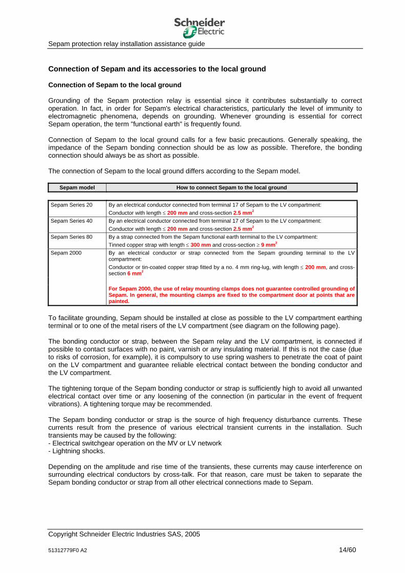
Sepam protection relay installation assistance guide Connection of Sepam and its accessories to the local ground Connection of Sepam to the local ground Grounding of the Sepam protection relay is essential since it contributes substantially to correct operation. In fact, in order for Sepam's electrical characteristics, particularly the level of immunity to electromagnetic phenomena, depends on grounding. Whenever grounding is essential for correct Sepam operation, the term "functional earth" is frequently found. Connection of Sepam to the local ground calls for a few basic precautions. Generally speaking, the impedance of the Sepam bonding connection should be as low as possible. Therefore, the bonding connection should always be as short as possible. The connection of Sepam to the local ground differs according to the Sepam model.
Sepam model How to connect Sepam to the local ground Sepam Series 20 By an electrical conductor connected from terminal 17 of Sepam to the LV compartment:
Conductor with length ≤ 200 mm and cross-section 2.5 mm2 Sepam Series 40 By an electrical conductor connected from terminal 17 of Sepam to the LV compartment:
Conductor with length ≤ 200 mm and cross-section 2.5 mm2
Sepam Series 80 By a strap connected from the Sepam functional earth terminal to the LV compartment: Tinned copper strap with length ≤ 300 mm and cross-section ≥ 9 mm2
Sepam 2000 By an electrical conductor or strap connected from the Sepam grounding terminal to the LV compartment: Conductor or tin-coated copper strap fitted by a no. 4 mm ring-lug, with length ≤ 200 mm, and cross-section 6 mm2
For Sepam 2000, the use of relay mounting clamps does not guarantee controlled grounding of
Sepam. In general, the mounting clamps are fixed to the compartment door at points that are painted.
To facilitate grounding, Sepam should be installed at close as possible to the LV compartment earthing terminal or to one of the metal risers of the LV compartment (see diagram on the following page). The bonding conductor or strap, between the Sepam relay and the LV compartment, is connected if possible to contact surfaces with no paint, varnish or any insulating material. If this is not the case (due to risks of corrosion, for example), it is compulsory to use spring washers to penetrate the coat of paint on the LV compartment and guarantee reliable electrical contact between the bonding conductor and the LV compartment. The tightening torque of the Sepam bonding conductor or strap is sufficiently high to avoid all unwanted electrical contact over time or any loosening of the connection (in particular in the event of frequent vibrations). A tightening torque may be recommended. The Sepam bonding conductor or strap is the source of high frequency disturbance currents. These currents result from the presence of various electrical transient currents in the installation. Such transients may be caused by the following: - Electrical switchgear operation on the MV or LV network - Lightning shocks. Depending on the amplitude and rise time of the transients, these currents may cause interference on surrounding electrical conductors by cross-talk. For that reason, care must be taken to separate the Sepam bonding conductor or strap from all other electrical connections made to Sepam.
Copyright Schneider Electric Industries SAS, 2005 51312779F0 A2 14/60

Sepam protection relay installation assistance guide
LV compartment
Sepam
Sepam is grounded according toSEI instructions.The Sepam bonding connection isSeparated from the other connections made to Sepam.
Sepam is installed in the LV compartment, near theLV compartment earthing terminal or, by default, nearone of the metal risers of the LV compartment.
The Sepam bonding connection is supportedby a surface with no paint, varnish or anyInsulating material.If these conditions are not met,spring washers must be used.
Metal riserof the LV compartment
Local ground (G0)
Electrical protection
Copyright Schneider Electric Industries SAS, 2005 51312779F0 A2 15/60
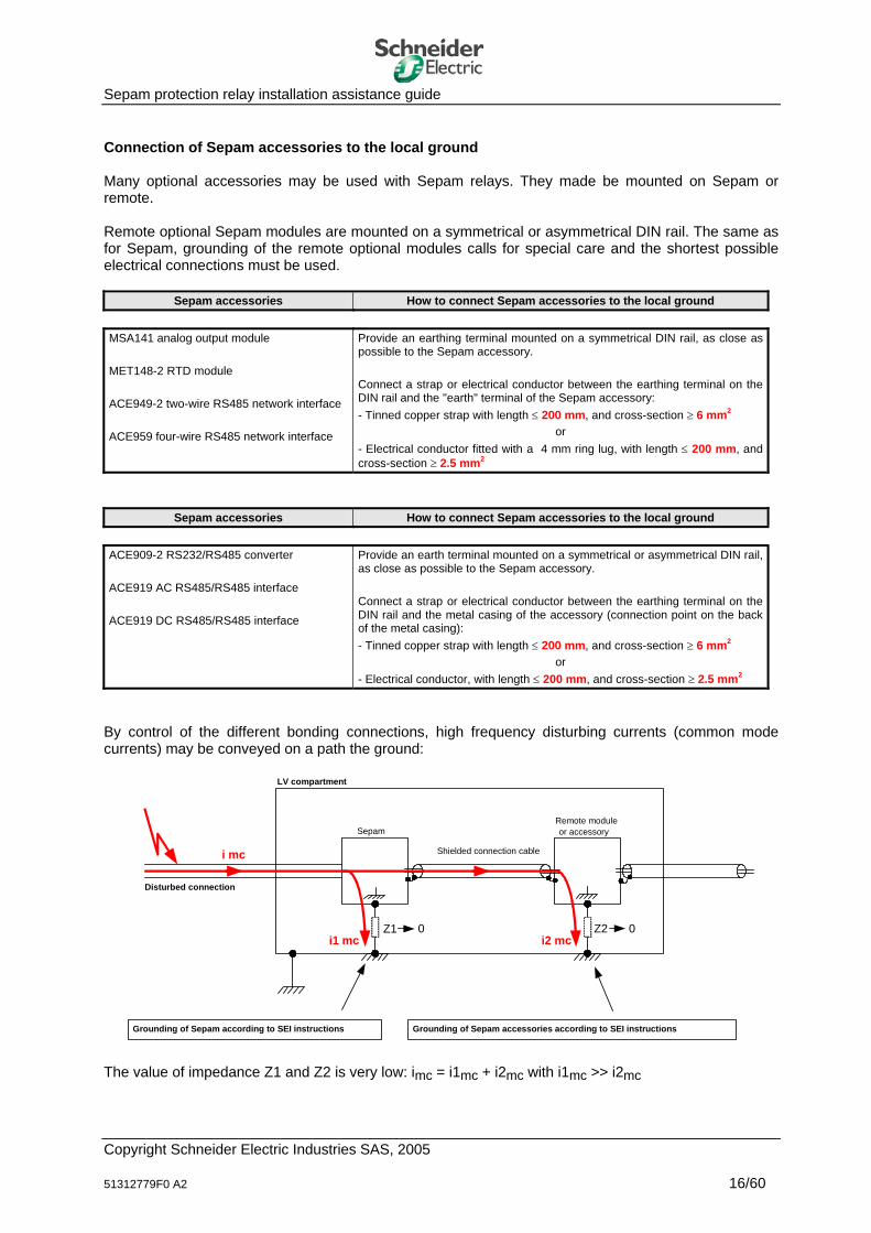
Sepam protection relay installation assistance guide Connection of Sepam accessories to the local ground Many optional accessories may be used with Sepam relays. They made be mounted on Sepam or remote. Remote optional Sepam modules are mounted on a symmetrical or asymmetrical DIN rail. The same as for Sepam, grounding of the remote optional modules calls for special care and the shortest possible electrical connections must be used.
Sepam accessories How to connect Sepam accessories to the local ground MSA141 analog output module MET148-2 RTD module ACE949-2 two-wire RS485 network interface ACE959 four-wire RS485 network interface
Provide an earthing terminal mounted on a symmetrical DIN rail, as close as possible to the Sepam accessory. Connect a strap or electrical conductor between the earthing terminal on the DIN rail and the "earth" terminal of the Sepam accessory: - Tinned copper strap with length ≤ 200 mm, and cross-section ≥ 6 mm2
or - Electrical conductor fitted with a 4 mm ring lug, with length ≤ 200 mm, and cross-section ≥ 2.5 mm2
Sepam accessories How to connect Sepam accessories to the local ground ACE909-2 RS232/RS485 converter ACE919 AC RS485/RS485 interface ACE919 DC RS485/RS485 interface
Provide an earth terminal mounted on a symmetrical or asymmetrical DIN rail, as close as possible to the Sepam accessory. Connect a strap or electrical conductor between the earthing terminal on the DIN rail and the metal casing of the accessory (connection point on the back of the metal casing): - Tinned copper strap with length ≤ 200 mm, and cross-section ≥ 6 mm2
or - Electrical conductor, with length ≤ 200 mm, and cross-section ≥ 2.5 mm2
By control of the different bonding connections, high frequency disturbing currents (common mode currents) may be conveyed on a path the ground:
LV compartment
SepamRemote moduleor accessory
Disturbed connection
Shielded connection cablei mc
i1 mc i2 mc
Grounding of Sepam according to SEI instructions Grounding of Sepam accessories according to SEI instructions
Z1 0 Z2 0
The value of impedance Z1 and Z2 is very low: imc = i1mc + i2mc with i1mc >> i2mc
Copyright Schneider Electric Industries SAS, 2005 51312779F0 A2 16/60
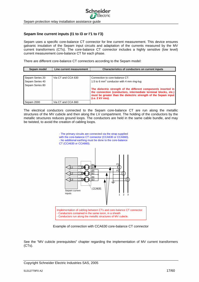
Sepam protection relay installation assistance guide Sepam line current inputs (I1 to I3 or I'1 to I'3) Sepam uses a specific core-balance CT connector for line current measurement. This device ensures galvanic insulation of the Sepam input circuits and adaptation of the currents measured by the MV current transformers (CTs). The core-balance CT connector includes a highly sensitive (low level) current measurement core-balance CT for each phase. There are different core-balance CT connectors according to the Sepam model:
Sepam model Line current measurement Characteristics of conductors on current inputs Sepam Series 20 Sepam Series 40 Sepam Series 80
Via CT and CCA 630 Connection to core-balance CT: 1.5 to 6 mm2 conductor with 4 mm ring-lug
The dielectric strength of the different components inserted in the connection (conductors, intermediate terminal blocks, etc.) must be greater than the dielectric strength of the Sepam input (i.e. 2 kV rms).
Sepam 2000 Via CT and CCA 660
The electrical conductors connected to the Sepam core-balance CT are run along the metallic structures of the MV cubicle and then along the LV compartment. The holding of the conductors by the metallic structures reduces ground loops. The conductors are held in the same cable bundle, and may be twisted, to avoid the creation of cabling loops.
EM
L1
Sepam current inputs
L2
L3
P1
P2
B4B1B5B2B6B3
CCA630
1 2 3
- The primary circuits are connected via the strap suppliedwith the core-balance CT connector (CCA630 or CCA660).- No additional earthing must be done to the core-balanceCT (CCA630 or CCA660).
Implementation of cabling between CTs and core-balance CT connector: - Conductors contained in the same toron, in a sheath - Conductors run along the metallic structures of MV cubicle.
Example of connection with CCA630 core-balance CT connector See the "MV cubicle prerequisites" chapter regarding the implementation of MV current transformers (CTs).
Copyright Schneider Electric Industries SAS, 2005 51312779F0 A2 17/60
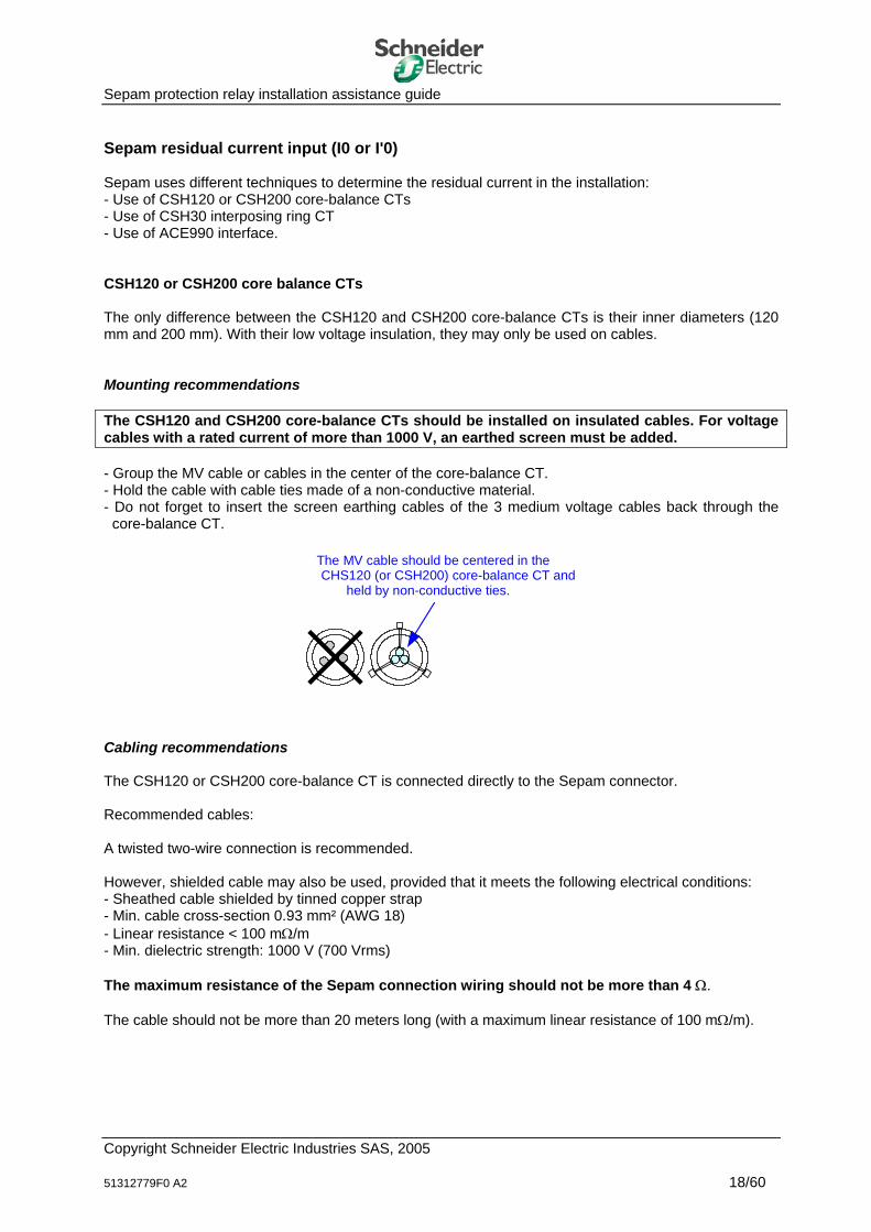
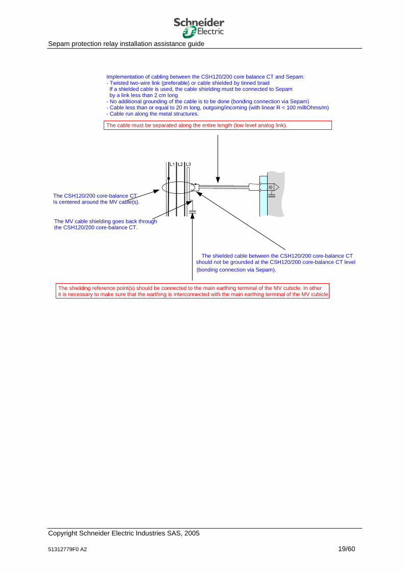
Sepam protection relay installation assistance guide Sepam residual current input (I0 or I'0) Sepam uses different techniques to determine the residual current in the installation: - Use of CSH120 or CSH200 core-balance CTs - Use of CSH30 interposing ring CT - Use of ACE990 interface. CSH120 or CSH200 core balance CTs The only difference between the CSH120 and CSH200 core-balance CTs is their inner diameters (120 mm and 200 mm). With their low voltage insulation, they may only be used on cables. Mounting recommendations The CSH120 and CSH200 core-balance CTs should be installed on insulated cables. For voltage cables with a rated current of more than 1000 V, an earthed screen must be added. - Group the MV cable or cables in the center of the core-balance CT. - Hold the cable with cable ties made of a non-conductive material. - Do not forget to insert the screen earthing cables of the 3 medium voltage cables back through the
core-balance CT.
The MV cable should be centered in theCHS120 (or CSH200) core-balance CT and
held by non-conductive ties.
Cabling recommendations The CSH120 or CSH200 core-balance CT is connected directly to the Sepam connector. Recommended cables: A twisted two-wire connection is recommended. However, shielded cable may also be used, provided that it meets the following electrical conditions: - Sheathed cable shielded by tinned copper strap - Min. cable cross-section 0.93 mm² (AWG 18) - Linear resistance < 100 mΩ/m - Min. dielectric strength: 1000 V (700 Vrms) The maximum resistance of the Sepam connection wiring should not be more than 4 Ω. The cable should not be more than 20 meters long (with a maximum linear resistance of 100 mΩ/m).
Copyright Schneider Electric Industries SAS, 2005 51312779F0 A2 18/60
Sepam protection relay installation assistance guide
The shielded cable between the CSH120/200 core-balance CTshould not be grounded at the CSH120/200 core-balance CT level(bonding connection via Sepam).
The MV cable shielding goes back through the CSH120/200 core-balance CT.
The cable must be separated along the entire length (low level analog link).
The shielding reference point(s) should be connected to the main earthing terminal of the MV cubicle. In other it is necessary to make sure that the earthing is interconnected with the main earthing terminal of the MV cubicle.
The CSH120/200 core-balance CT Is centered around the MV cable(s).
Implementation of cabling between the CSH120/200 core balance CT and Sepam: - Twisted two-wire link (preferable) or cable shielded by tinned braid If a shielded cable is used, the cable shielding must be connected to Sepam by a link less than 2 cm long- No additional grounding of the cable is to be done (bonding connection via Sepam) - Cable less than or equal to 20 m long, outgoing/incoming (with linear R < 100 milliOhms/m) - Cable run along the metal structures.
Copyright Schneider Electric Industries SAS, 2005 51312779F0 A2 19/60

Sepam protection relay installation assistance guide CSH30 interposing ring CT The CSH30 interposing ring CT is used when residual current is measured by a current transformer with a 1A or 5A secondary circuit. The CSH30 interposing ring CT adapts the signals between the current transformer and the Sepam residual current input. The CSH30 interposing ring CT is mounted on a symmetrical DIN rail. It may also be mounted on a metallic plate using the mounting holes provided in its base. Mounting recommendations The CSH30 interposing ring CT should be installed in an area of the LV compartment in which the magnetic activity is low so as not to be disturbed (risk of erroneous measurements). The CT should be kept away from 50 Hz supply transformers and power cables in particular (risk of measurement interference by the magnetic field radiated by such components). Cabling recommendations The secondary circuit of the CSH30 is connected directly to the Sepam connector. Cable to be used between the CSH30 interposing ring CT and Sepam: A twisted two-wire connection is recommended. However, shielded cable may also be used, provided that it meets the following electrical conditions: - Sheathed cable shielded by tinned copper strap - Min. cable cross-section 0.93 mm² (AWG 18) (max. 2.5 mm²) - Linear resistance < 100 mΩ/m - Minimum dielectric strength: 1000 V (700 V rms) for functional reasons - Maximum cable length of 2 m.
Implementation of cabling between the CSH30 and Sepam: - Twisted two-wire connection (preferable) or cable shielded by tinned braid. If a shielded cable is used, the cable shielding must be connected to Sepam by a link less than 2 cm long.- No cable grounding to be done (bonding connection via Sepam) - Cable less than or equal to 2 m long (with linear R < 100 milliOhms/m) - Cable run along metal structures.
Earthing of the secondary of the MV core-balance CT:- The secondary is earthed via a copper bar, as short aspossible, with a rectangular cross-section. - The main earthing terminal of the MV cubicle provides reference potential for the MV core-balance CT.
Implementation of the link between the MV core-balance CTand the CSH30 interposing ring CT: - The conductors connected to the secondary circuit of theMV core-balance CT are held in the same strand, in a sheathso as not to create loops. - The conductors are run along the metallic structures of the MV cubicle.
Copyright Schneider Electric Industries SAS, 2005 51312779F0 A2 20/60
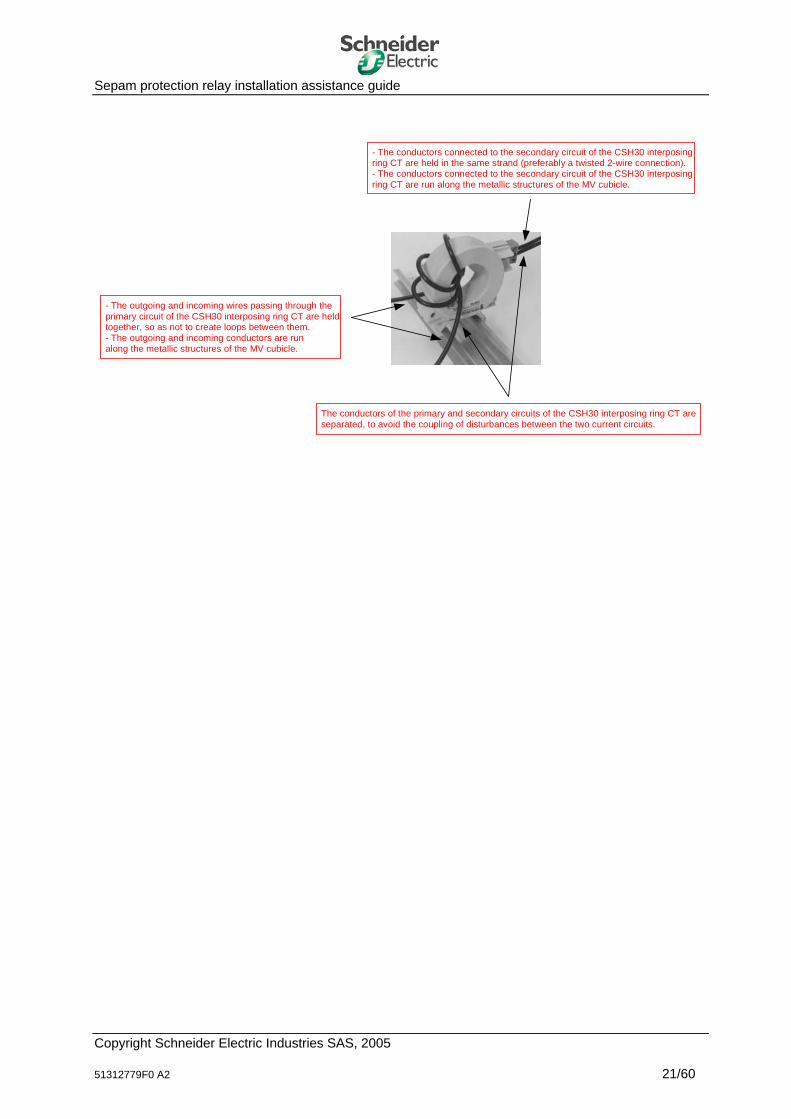
Sepam protection relay installation assistance guide - The conductors connected to the secondary circuit of the CSH30 interposing
ring CT are held in the same strand (preferably a twisted 2-wire connection).- The conductors connected to the secondary circuit of the CSH30 interposingring CT are run along the metallic structures of the MV cubicle.
- The outgoing and incoming wires passing through the primary circuit of the CSH30 interposing ring CT are heldtogether, so as not to create loops between them. - The outgoing and incoming conductors are run along the metallic structures of the MV cubicle.
The conductors of the primary and secondary circuits of the CSH30 interposing ring CT areseparated, to avoid the coupling of disturbances between the two current circuits.
Copyright Schneider Electric Industries SAS, 2005 51312779F0 A2 21/60
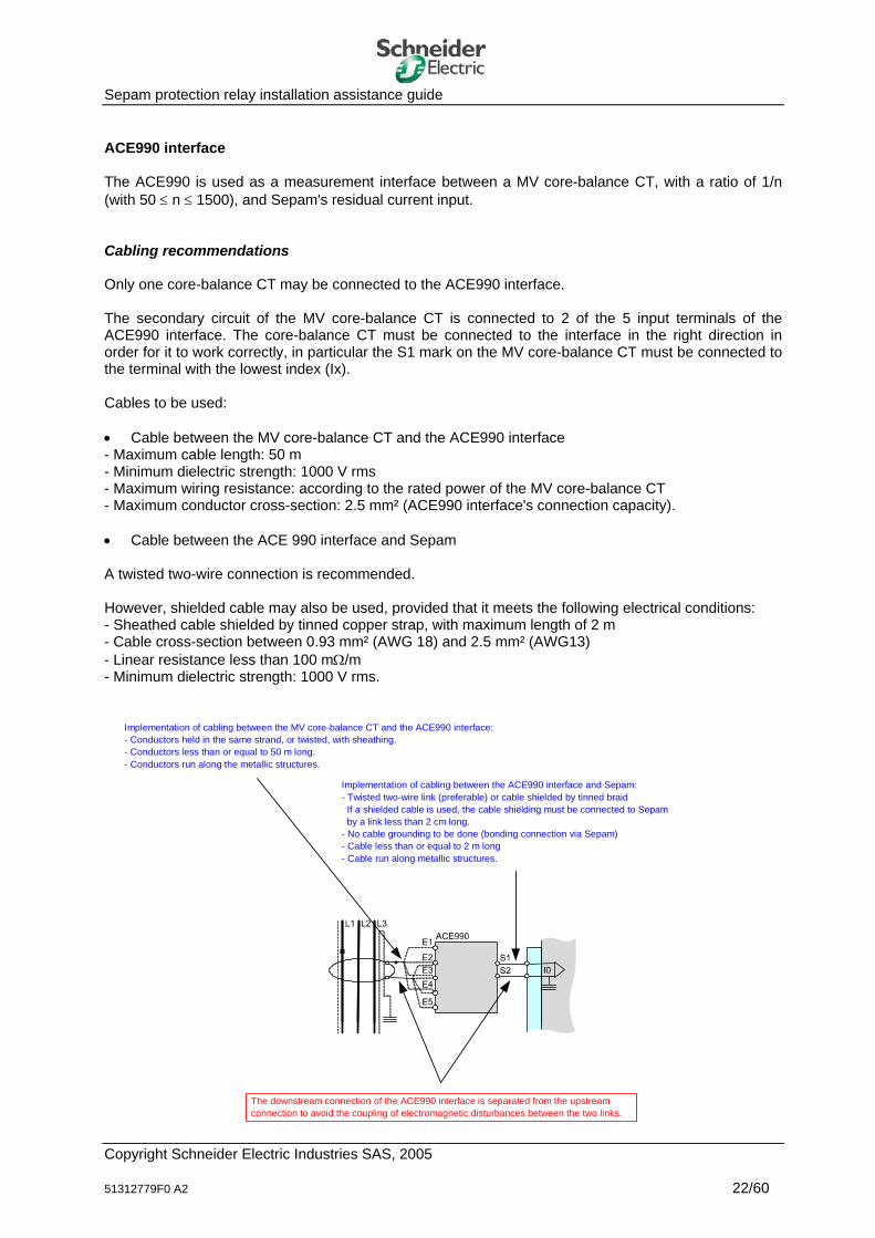
Sepam protection relay installation assistance guide ACE990 interface The ACE990 is used as a measurement interface between a MV core-balance CT, with a ratio of 1/n (with 50 ≤ n ≤ 1500), and Sepam's residual current input. Cabling recommendations Only one core-balance CT may be connected to the ACE990 interface. The secondary circuit of the MV core-balance CT is connected to 2 of the 5 input terminals of the ACE990 interface. The core-balance CT must be connected to the interface in the right direction in order for it to work correctly, in particular the S1 mark on the MV core-balance CT must be connected to the terminal with the lowest index (Ix). Cables to be used: • Cable between the MV core-balance CT and the ACE990 interface - Maximum cable length: 50 m - Minimum dielectric strength: 1000 V rms - Maximum wiring resistance: according to the rated power of the MV core-balance CT - Maximum conductor cross-section: 2.5 mm² (ACE990 interface's connection capacity). • Cable between the ACE 990 interface and Sepam A twisted two-wire connection is recommended. However, shielded cable may also be used, provided that it meets the following electrical conditions: - Sheathed cable shielded by tinned copper strap, with maximum length of 2 m - Cable cross-section between 0.93 mm² (AWG 18) and 2.5 mm² (AWG13) - Linear resistance less than 100 mΩ/m - Minimum dielectric strength: 1000 V rms.
Implementation of cabling between the MV core-balance CT and the ACE990 interface:- Conductors held in the same strand, or twisted, with sheathing.- Conductors less than or equal to 50 m long. - Conductors run along the metallic structures.
Implementation of cabling between the ACE990 interface and Sepam: - Twisted two-wire link (preferable) or cable shielded by tinned braid If a shielded cable is used, the cable shielding must be connected to Sepam by a link less than 2 cm long.- No cable grounding to be done (bonding connection via Sepam) - Cable less than or equal to 2 m long- Cable run along metallic structures.
The downstream connection of the ACE990 interface is separated from the upstream connection to avoid the coupling of electromagnetic disturbances between the two links.
Copyright Schneider Electric Industries SAS, 2005 51312779F0 A2 22/60

Sepam protection relay installation assistance guide Sepam voltage inputs (U21, U32, U13, V0, V1, V2, V3) Sepam acquires voltage measurements via the MV voltage transformers (VTs) or via the specific CCT640 connector. The CCT 640 connector contains 4 transformers. It ensures the galvanic insulation of the Sepam input circuits and adaptation of the signals measured by the Sepam MV voltage transformers (VTs). The connection of the voltage inputs differs according to the Sepam model:
Sepam model Voltage measurement Characteristics of conductors on voltage inputs Sepam Series 20 Via VT and CCT 640 Connection to CCT 640 connector:
1 conductor per terminal, 0.2 to 2.5 mm2 max. The dielectric strength of the different components
inserted in the connection (conductors, intermediate terminal blocks, etc.) must be greater than the dielectric strength of the Sepam input (i.e. 2 kV rms).
Sepam Series 40 Measurement supplied by VT Connection to Sepam: 1 conductor per terminal, 0.2 to 2.5 mm2 max.
The dielectric strength of the different components inserted in the connection (conductors, intermediate terminal blocks, etc.) must be greater than the dielectric strength of the Sepam input (i.e. 2 kV rms).
Sepam Series 80 Via VT and/or CCT 640 Connection to CCT 640 connector: 1 conductor per terminal, 0.2 to 2.5 mm2 max.
The dielectric strength of the different components inserted in the connection (conductors, intermediate terminal blocks, etc.) must be greater than the dielectric strength of the Sepam input (i.e. 2 kV rms).
Sepam 2000 Measurement supplied by VT Connection to Sepam: 1 conductor per terminal, 2.5 mm2 max.
The dielectric strength of the different components inserted in the connection (conductors, intermediate terminal blocks, etc.) must be greater than the dielectric strength of the Sepam input (i.e. 2 kV rms).
The electrical conductors connected to the Sepam voltage inputs or to the CCT640 voltage adapter terminals are run along the metallic structures of the MV cubicle and then along the LV compartment. Running them along the metallic structures reduces ground loops. The conductors are held in the same strand, and may be twisted, to avoid the creation of cabling loops.
! Warning The CCT640 connector may be disconnected from the Sepam relay, even when the MV voltage transformers (VTs) are energized. To guarantee the safety of people, the CCT640 connector must be connected to an electrical protection conductor. A connection terminal is provided on the CCT640 connector for that purpose. See the diagram on the following page.
Copyright Schneider Electric Industries SAS, 2005 51312779F0 A2 23/60
Sepam protection relay installation assistance guide L1
L2 L3
B4B5B6
B7B8
B3
B1B2
CCT640
V1
V2
V3
Vo
Sepaminputs
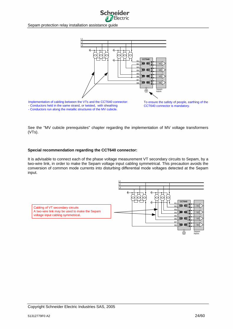
To ensure the safety of people, earthing of theCCT640 connector is mandatory.
Implementation of cabling between the VTs and the CCT640 connector:- Conductors held in the same strand, or twisted, with sheathing- Conductors run along the metallic structures of the MV cubicle.
See the "MV cubicle prerequisites" chapter regarding the implementation of MV voltage transformers (VTs). Special recommendation regarding the CCT640 connector: It is advisable to connect each of the phase voltage measurement VT secondary circuits to Sepam, by a two-wire link, in order to make the Sepam voltage input cabling symmetrical. This precaution avoids the conversion of common mode currents into disturbing differential mode voltages detected at the Sepam input.
L1L2
L3
B4B5B6
B7B8
B3
B1B2
CCT640
V1
V2
V3
Vo
Sepamminputs
Cabling of VT secondary circuitsA two-wire link may be used to make the Sepamvoltage input cabling symmetrical.
Copyright Schneider Electric Industries SAS, 2005 51312779F0 A2 24/60
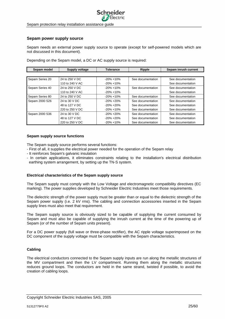
Sepam protection relay installation assistance guide Sepam power supply source Sepam needs an external power supply source to operate (except for self-powered models which are not discussed in this document). Depending on the Sepam model, a DC or AC supply source is required:
Sepam model Supply voltage Tolerance Ripple Sepam inrush current Sepam Series 20 24 to 250 V DC -20% +10% See documentation See documentation 110 to 240 V AC -20% +10% See documentation Sepam Series 40 24 to 250 V DC -20% +10% See documentation See documentation 110 to 240 V AC -20% +10% See documentation Sepam Series 80 24 to 250 V DC -20% +10% See documentation See documentation Sepam 2000 S26 24 to 30 V DC -20% +20% See documentation See documentation 48 to 127 V DC -20% +20% See documentation See documentation 220 to 250 V DC -20% +10% See documentation See documentation Sepam 2000 S36 24 to 30 V DC -20% +20% See documentation See documentation 48 to 127 V DC -20% +20% See documentation See documentation 220 to 250 V DC -20% +10% See documentation See documentation
Sepam supply source functions The Sepam supply source performs several functions: - First of all, it supplies the electrical power needed for the operation of the Sepam relay - It reinforces Sepam's galvanic insulation - In certain applications, it eliminates constraints relating to the installation's electrical distribution
earthing system arrangement, by setting up the TN-S system. Electrical characteristics of the Sepam supply source The Sepam supply must comply with the Low Voltage and electromagnetic compatibility directives (EC marking). The power supplies developed by Schneider Electric Industries meet those requirements. The dielectric strength of the power supply must be greater than or equal to the dielectric strength of the Sepam power supply (i.e. 2 kV rms). The cabling and connection accessories inserted in the Sepam supply lines must also meet that requirement. The Sepam supply source is obviously sized to be capable of supplying the current consumed by Sepam and must also be capable of supplying the inrush current at the time of the powering up of Sepam (or of the number of Sepam units present). For a DC power supply (full wave or three-phase rectifier), the AC ripple voltage superimposed on the DC component of the supply voltage must be compatible with the Sepam characteristics. Cabling The electrical conductors connected to the Sepam supply inputs are run along the metallic structures of the MV compartment and then the LV compartment. Running them along the metallic structures reduces ground loops. The conductors are held in the same strand, twisted if possible, to avoid the creation of cabling loops.
Copyright Schneider Electric Industries SAS, 2005 51312779F0 A2 25/60
Sepam protection relay installation assistance guide Also, when the Sepam supply lines include a protective earth conductor (PE), the PE must be run with the active supply conductors (+ polarity and 0V for DC supply, phase and neutral for AC supply). Installation of the Sepam supply source The supply source may be common to several electronic equipment items in the LV compartment. It can supply equipment other than Sepam protection relays (electronic devices, actuators, etc.). The Sepam supply source is either integrated in the LV compartment or transferred outside the compartment. a) Sepam supply source integrated in the LV compartment It is preferable for the supply source to be integrated in the LV compartment. Whatever the type of supply source required, the LV compartment should be designed to house and facilitate the implementation of the following components: - An isolation transformer if the earthing system arrangement is IT or TN-C (only in the case of Sepam
AC supply) - A surge suppressor if the installation is situated in an area highly exposed to lightning (overhead MV
line, lightning strike density > 1) - An EMC filter if the installation is located in a highly disturbed electromagnetic environment (e.g. very
high power motor, very high power converter) These components should be included as of the point at which the supply conductors enter the LV compartment. When the supply sources are mounted on a DIN rail, a ground terminal can be used to ground-reference the 0V (or the neutral) of the Sepam supply source. b) Sepam supply source transferred outside the LV compartment The Sepam supply source may be transferred outside the LV compartment (e.g. installed in an auxiliary distribution panel). In such cases, particular precautions must be considered. The Sepam supply conductors may be source of disturbing currents, induced by the presence of surrounding conductors (e.g. power conductors). These disturbing currents are conveyed on the Sepam supply lines and may alter Sepam operation. In such conditions, make sure that the power supply conductors are held together (use of a twisted wire connection) and run along the metallic structures of the installation. Nevertheless, these precautions may sometimes prove to be insufficient, since the equipotential bonding in the installation is not guaranteed or because the proximity of disturbing devices in the vicinity is too great a constraint. Overvoltage protection and an electromagnetic interference filter are recommended in the LV compartment. These components should be included as of the point at which the supply conductors enter the LV compartment (see paragraph above for more information).
Copyright Schneider Electric Industries SAS, 2005 51312779F0 A2 26/60

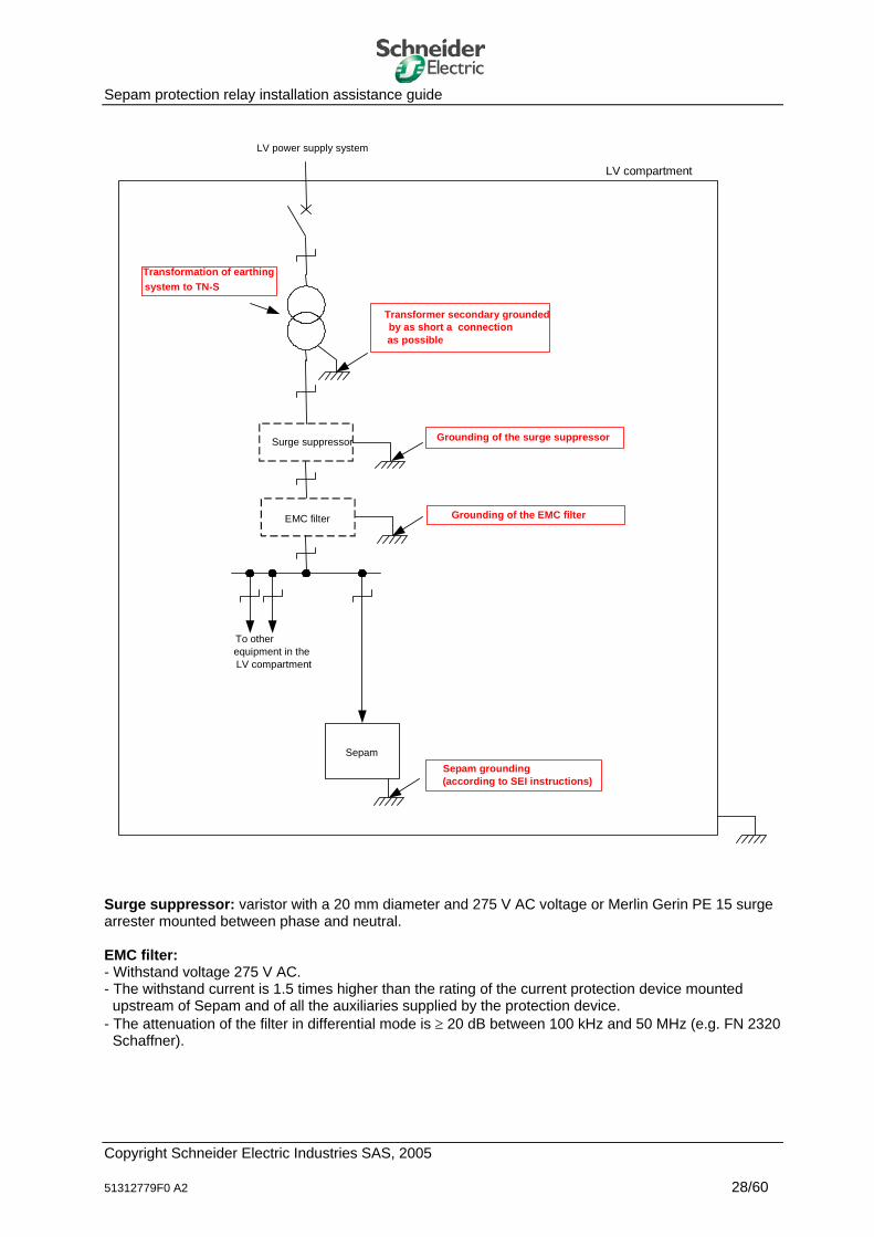
Sepam protection relay installation assistance guide LV compartment supply by an AC power system Sepam requires AC supply voltage or DC supply voltage. a) Sepam requires AC supply voltage The Sepam electrical power supply should be as similar as possible to the diagram below: • General overcurrent protection • Use of an isolation transformer (if the TN-S or TT earthing system arrangement is not guaranteed in
the installation)
This transformer calls for a TN-S earthing system arrangement (transformer secondary reference by as short a connection as possible). The isolation transformer is aimed at: - Completely eliminating the constraints of the installation's earthing system arrangement - Isolating the Sepam supply lines from any disturbing devices that may be connected to the LV
power system (e.g. motors) - Eliminating the impact of any modifications on the installation's electrical distribution system.
• Use of a surge suppressor and an EMC filter if necessary
These components are particularly recommended when Sepam is implemented in environments with high levels of electromagnetic interference.
• Star-type distribution of AC power supplies to the different equipment items in the LV compartment.
Copyright Schneider Electric Industries SAS, 2005 51312779F0 A2 27/60
Sepam protection relay installation assistance guide
LV compartment
Sepam
LV power supply system
To otherequipment in theLV compartment
Surge suppressor
EMC filter Grounding of the EMC filter
Grounding of the surge suppressor
Transformation of earthingsystem to TN-S
Transformer secondary grounded by as short a connection as possible
Sepam grounding(according to SEI instructions)
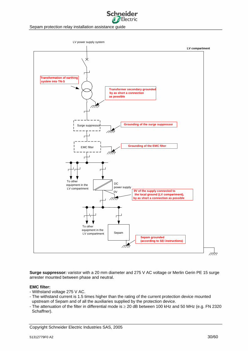
Surge suppressor: varistor with a 20 mm diameter and 275 V AC voltage or Merlin Gerin PE 15 surge arrester mounted between phase and neutral. EMC filter: - Withstand voltage 275 V AC. - The withstand current is 1.5 times higher than the rating of the current protection device mounted
upstream of Sepam and of all the auxiliaries supplied by the protection device. - The attenuation of the filter in differential mode is ≥ 20 dB between 100 kHz and 50 MHz (e.g. FN 2320
Schaffner).
Copyright Schneider Electric Industries SAS, 2005 51312779F0 A2 28/60
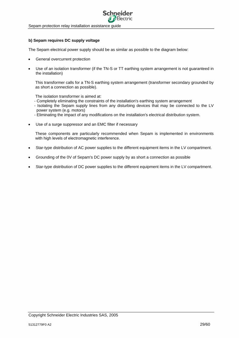
Sepam protection relay installation assistance guide b) Sepam requires DC supply voltage The Sepam electrical power supply should be as similar as possible to the diagram below: • General overcurrent protection • Use of an isolation transformer (if the TN-S or TT earthing system arrangement is not guaranteed in
the installation)
This transformer calls for a TN-S earthing system arrangement (transformer secondary grounded by as short a connection as possible). The isolation transformer is aimed at: - Completely eliminating the constraints of the installation's earthing system arrangement - Isolating the Sepam supply lines from any disturbing devices that may be connected to the LV
power system (e.g. motors) - Eliminating the impact of any modifications on the installation's electrical distribution system.
• Use of a surge suppressor and an EMC filter if necessary
These components are particularly recommended when Sepam is implemented in environments with high levels of electromagnetic interference.
• Star-type distribution of AC power supplies to the different equipment items in the LV compartment. • Grounding of the 0V of Sepam's DC power supply by as short a connection as possible • Star-type distribution of DC power supplies to the different equipment items in the LV compartment.
Copyright Schneider Electric Industries SAS, 2005 51312779F0 A2 29/60
Sepam protection relay installation assistance guide
LV compartment
Sepam
LV power supply system
0V of the supply connected tothe local ground (LV compartment),
by as short a connection as possible
To otherequipment in theLV compartment
Sepam grounded(according to SEI instructions)
To otherequipment in theLV compartment
Surge suppressor
EMC filter Grounding of the EMC filter
Grounding of the surge suppressor
Transformation of earthingthisystem into TN-S
Transformer secondary groundedby as short a connectionas possible
0V
DCpower supply
Surge suppressor: varistor with a 20 mm diameter and 275 V AC voltage or Merlin Gerin PE 15 surge arrester mounted between phase and neutral. EMC filter: - Withstand voltage 275 V AC. - The withstand current is 1.5 times higher than the rating of the current protection device mounted
upstream of Sepam and of all the auxiliaries supplied by the protection device. - The attenuation of the filter in differential mode is ≥ 20 dB between 100 kHz and 50 MHz (e.g. FN 2320
Schaffner).
Copyright Schneider Electric Industries SAS, 2005 51312779F0 A2 30/60

Sepam protection relay installation assistance guide Please note: In installations, Sepam is more and more often integrated in complex data management systems. It may be associated with a PLC dedicated to centralized installation management. A large number of data are exchanged between the Sepam protection relay and a PLC: logic inputs, logic outputs, analog data, etc. In this type of installation, attention must also be paid to the PLC power supply. It is preferable for the PLC to be supplied by an electrical distribution system that has a TN-S earthing system arrangement. Care must be taken regarding the distribution of the power supplies of the logic and analog inputs/outputs and large cabling loops of various power supplies must be avoided. Be careful as well not to short-circuit the galvanic insulation.
Copyright Schneider Electric Industries SAS, 2005 51312779F0 A2 31/60
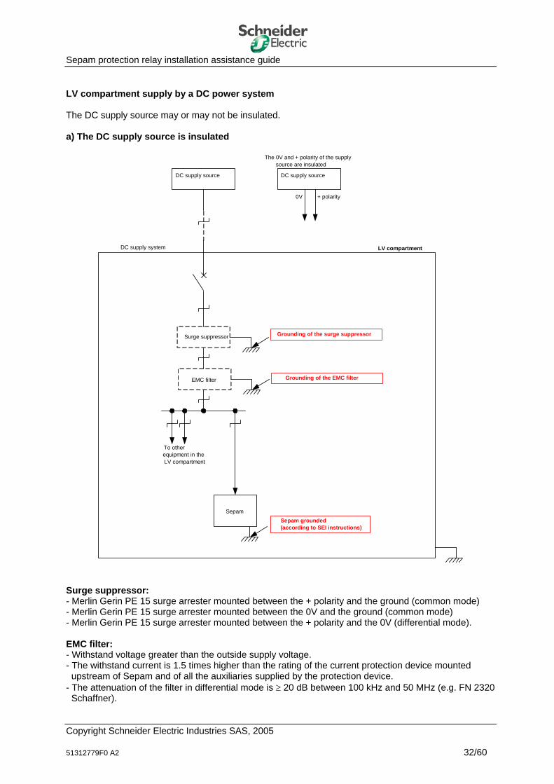
Sepam protection relay installation assistance guide LV compartment supply by a DC power system The DC supply source may or may not be insulated. a) The DC supply source is insulated
LV compartment
Sepam
DC supply system
To otherequipment in theLV compartment
Surge suppressor
EMC filter Grounding of the EMC filter
Grounding of the surge suppressor
Sepam grounded(according to SEI instructions)
DC supply source
The 0V and + polarity of the supplysource are insulated
DC supply source
0V + polarity
Surge suppressor: - Merlin Gerin PE 15 surge arrester mounted between the + polarity and the ground (common mode) - Merlin Gerin PE 15 surge arrester mounted between the 0V and the ground (common mode) - Merlin Gerin PE 15 surge arrester mounted between the + polarity and the 0V (differential mode). EMC filter: - Withstand voltage greater than the outside supply voltage. - The withstand current is 1.5 times higher than the rating of the current protection device mounted
upstream of Sepam and of all the auxiliaries supplied by the protection device. - The attenuation of the filter in differential mode is ≥ 20 dB between 100 kHz and 50 MHz (e.g. FN 2320
Schaffner).
Copyright Schneider Electric Industries SAS, 2005 51312779F0 A2 32/60

Sepam protection relay installation assistance guide Note regarding the use of insulation fault detectors: The use of an insulated DC power supply system is often characteristic of a need for continuity of service. The monitoring of the insulated system calls for the use of an insulation fault detector. The use of an insulation fault monitor for DC supply systems may cause operating problems in some cases. Certain insulation fault detectors do not detect faults that are symmetrical between + and – with respect to the earth. Wheatstone bridge insulation fault detectors with a middle point (ICE DTB 210 for example), in the event of an insulation fault or faulty pick-up setting (a few mA), can modify the impedance of the electronic circuits supplied with the earthed 0V. Insulation fault detectors that operate by the injection of an extra low frequency signal (a few Hz) between a polarity and earth may, in the event of insulation faults, inject into the system a voltage that can be superimposed on the installation's DC voltage. This can activate the security systems that monitor under or overvoltage, for example. When installing such devices, it is advisable to check in the presence of an insulation fault that the Sepam relays do not show any operating problems.
Copyright Schneider Electric Industries SAS, 2005 51312779F0 A2 33/60
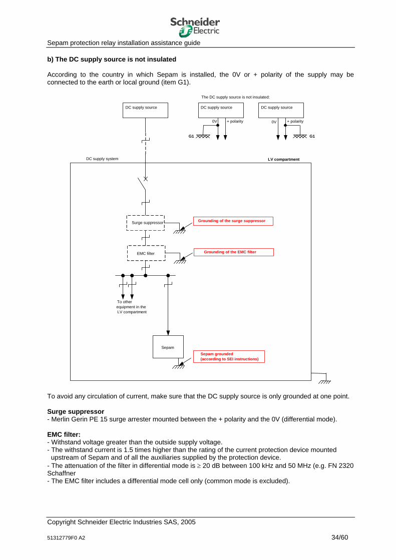
Sepam protection relay installation assistance guide b) The DC supply source is not insulated According to the country in which Sepam is installed, the 0V or + polarity of the supply may be connected to the earth or local ground (item G1).
LV compartment
Sepam
DC supply system
To otherequipment in theLV compartment
Surge suppressor
EMC filter Grounding of the EMC filter
Grounding of the surge suppressor
Sepam grounded(according to SEI instructions)
DC supply source
The DC supply source is not insulated:
DC supply source
0V + polarity
G1
DC supply source
0V + polarity
G1
To avoid any circulation of current, make sure that the DC supply source is only grounded at one point. Surge suppressor - Merlin Gerin PE 15 surge arrester mounted between the + polarity and the 0V (differential mode). EMC filter: - Withstand voltage greater than the outside supply voltage. - The withstand current is 1.5 times higher than the rating of the current protection device mounted
upstream of Sepam and of all the auxiliaries supplied by the protection device. - The attenuation of the filter in differential mode is ≥ 20 dB between 100 kHz and 50 MHz (e.g. FN 2320 Schaffner - The EMC filter includes a differential mode cell only (common mode is excluded).
Copyright Schneider Electric Industries SAS, 2005 51312779F0 A2 34/60
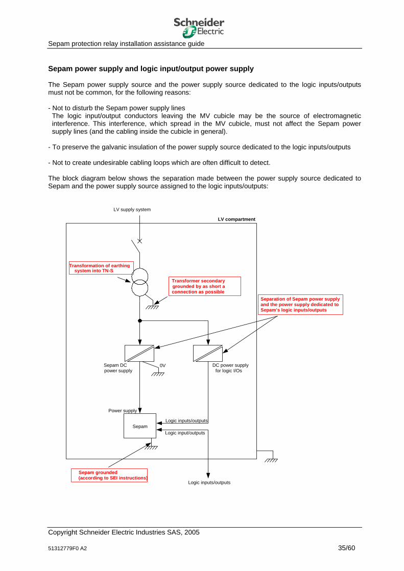
Sepam protection relay installation assistance guide Sepam power supply and logic input/output power supply The Sepam power supply source and the power supply source dedicated to the logic inputs/outputs must not be common, for the following reasons: - Not to disturb the Sepam power supply lines
The logic input/output conductors leaving the MV cubicle may be the source of electromagnetic interference. This interference, which spread in the MV cubicle, must not affect the Sepam power supply lines (and the cabling inside the cubicle in general).
- To preserve the galvanic insulation of the power supply source dedicated to the logic inputs/outputs - Not to create undesirable cabling loops which are often difficult to detect. The block diagram below shows the separation made between the power supply source dedicated to Sepam and the power supply source assigned to the logic inputs/outputs:
LV compartment
Sepam
Sepam DCpower supply
LV supply system
DC power supplyfor logic I/Os
Logic inputs/outputs
Logic inputs/outputs
Separation of Sepam power supplyand the power supply dedicated toSepam's logic inputs/outputs
0V
Transformer secondarygrounded by as short aconnection as possible
Transformation of earthingsystem into TN-S
Sepam grounded(according to SEI instructions)
Logic input/outputs
Power supply
Copyright Schneider Electric Industries SAS, 2005 51312779F0 A2 35/60

Sepam protection relay installation assistance guide Sepam's logic inputs (I1 to Ix or Ix1 to Ixx) Sepam has multiple logic type acquisition inputs. All of the logic inputs are insulated. The user may freely dispose of the logic inputs or they may be assigned to a predefined application (e.g. motor protection application). The logic inputs are potential-free and require an external power supply to operate (DC or AC supply source). The current consumed by the digital inputs is relatively low, about 4 mA (10 mA for old generations of Sepam 2000 logic inputs). The Sepam logic inputs are designed to operate over large distances. Given their very low electricity consumption and Sepam's high EMC immunity, in theory, the inputs can operate with conductors up to 5 km long (10 km outgoing and incoming). To reach such operating performance levels, it is however necessary to use shielded twisted pairs on Sepam's logic inputs. If it is not possible to use shielded twisted pairs, we recommend the following: - Limit the length of the electrical conductors connected to Sepam's digital inputs to 500 m (i.e. 1000 m
back and forth) - Use optical fiber or wireless data transmission. Types of Sepam logic inputs Sepam provides the user with two types of logic inputs: - Logic inputs insulated from the ground, with a common connection point - Logic inputs insulated from the ground and independent. The selection and correct use of the digital inputs are important to guarantee: - Correct operation of Sepam and, more broadly, of the installation - Availability of logical data. • Insulated logic inputs with a common connection point These logic inputs are insulated from the ground, but are not insulated in relation to each other (common point). They must be used to acquire logical data from the following digital sensors: - Insulated sensors - Sensors that are not insulated but come from the same zone of an installation with an equipotential
bonding network - Sensors that preferably come from the same equipment (e.g. a motor). The different logic data are contained in the same cable. • Insulated, independent logic inputs These logic inputs are also insulated from the ground, but they are also insulated from each other. They must be used to acquire data from the following digital sensors: - Non-insulated sensors (earthed) - Remote sensors - Sensors from several zones in the installation that does not have an equipotential bonding network - Sensors from different equipment items. To guarantee the insulation of each logic input, it is essential for each logic data item to be contained in an independent cable.
Copyright Schneider Electric Industries SAS, 2005 51312779F0 A2 36/60

Sepam protection relay installation assistance guide Cabling The electrical conductors connected to Sepam's logic inputs are run along the metallic structures of the MV cubicle and then the LV compartment. Running them against the metallic structures reduces ground loops. The conductors are held in the same strand and, if possible, twisted, to avoid the creation of cabling loops. When the environment and installation conditions are highly unfavorable for Sepam, a shielded twisted pair is used. In such cases, the cable shielding is connected to the local ground at both ends (provided that the installation has an equipotential bonding network).
Sepam model Characteristics of logic input conductors Sepam Series 20 Twisted two-wire link Sepam Series 40 1 conductor per terminal, 0.2 to 2.5 mm2 max. Sepam Series 80 The dielectric strength of the different components inserted in the connection
(conductors, intermediate terminal blocks, etc.) must be greater than the dielectric strength of the Sepam input (i.e. 2 kV rms).
Sepam 2000 Twisted two-wire link 1 conductor per terminal, 2.5 mm² max. The dielectric strength of the different components inserted in the connection
(conductors, intermediate terminal blocks, etc.) must be greater than the dielectric strength of the Sepam input (i.e. 2 kV rms).
Logic input power supply source The external power source used to supply Sepam's logic inputs must comply with the Low Voltage and electromagnetic compatibility directives (EC marking). The power supplies developed by Schneider Electric Industries meet those requirements. The dielectric strength of the supply source must be greater than or equal to the dielectric strength of Sepam's logic inputs (i.e. 2 kV rms). Sepam logic input cabling configurations First of all, we recommend that you distinguish between the logic inputs used in the application and the logic inputs that are not used. To further reinforce Sepam's level of immunity, we recommend that you short-circuit the connection terminals of the logic inputs that are not used in the application. To do this, an electrical conductor as short as possible is wired directly between the two terminals of the unused logic input connector. To make it easier to read the diagrams in this chapter, this particular point is not represented in the different diagrams on the pages which follow. In each application, a distinction should be made between the logic inputs that remain within the perimeter of the MV cubicle and those that leave the MV cubicle. To illustrate this, we will give a few cases of use of insulated, independent logic inputs.
Configuration Logic input power supply source Digital sensor Configuration n° 1 Inside the LV compartment Inside the LV compartment Configuration n° 2 Inside the LV compartment Outside the LV compartment, insulated Outside the LV compartment, ground-
referenced Configuration n° 3 Outside the LV compartment Outside the LV compartment
Each configuration is illustrated in the pages which follow by a simple electrical diagram.
Copyright Schneider Electric Industries SAS, 2005 51312779F0 A2 37/60
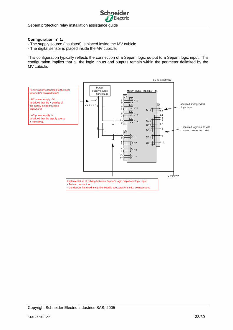
Sepam protection relay installation assistance guide Configuration n° 1: - The supply source (insulated) is placed inside the MV cubicle - The digital sensor is placed inside the MV cubicle. This configuration typically reflects the connection of a Sepam logic output to a Sepam logic input. This configuration implies that all the logic inputs and outputs remain within the perimeter delimited by the MV cubicle.
Powersupply source
(insulated)
LV compartment
Power supply connected to the local ground (LV compartment): - DC power supply: 0V (provided that the + polarity of the supply is not grounded elsewhere) - AC power supply: N (provided that the supply source is insulated).
Implementation of cabling between Sepam's logic output and logic input:- Twisted conductors - Conductors flattened along the metallic structures of the LV compartment.
Insulated, independentlogic input
Insulated logic inputs withcommon connection point
Copyright Schneider Electric Industries SAS, 2005 51312779F0 A2 38/60
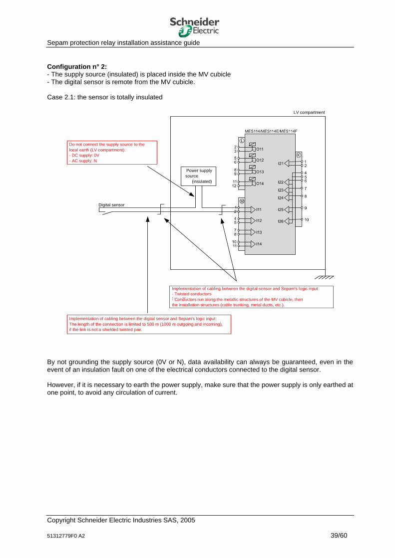
Sepam protection relay installation assistance guide Configuration n° 2: - The supply source (insulated) is placed inside the MV cubicle - The digital sensor is remote from the MV cubicle. Case 2.1: the sensor is totally insulated
Digital sensor
LV compartment
Implementation of cabling between the digital sensor and Sepam's logic input: - Twisted conductors torsadés- Conductors run along the metallic structures of the MV cubicle, then the installation structures (cable trunking, metal ducts, etc.).
Implementation of cabling between the digital sensor and Sepam's logic input:The length of the connection is limited to 500 m (1000 m outgoing and incoming), if the link is not a shielded twisted pair.
Power supplysource
(insulated)
Do not connect the supply source to the local earth (LV compartment): - DC supply: 0V - AC supply: N
By not grounding the supply source (0V or N), data availability can always be guaranteed, even in the event of an insulation fault on one of the electrical conductors connected to the digital sensor. However, if it is necessary to earth the power supply, make sure that the power supply is only earthed at one point, to avoid any circulation of current.
Copyright Schneider Electric Industries SAS, 2005 51312779F0 A2 39/60
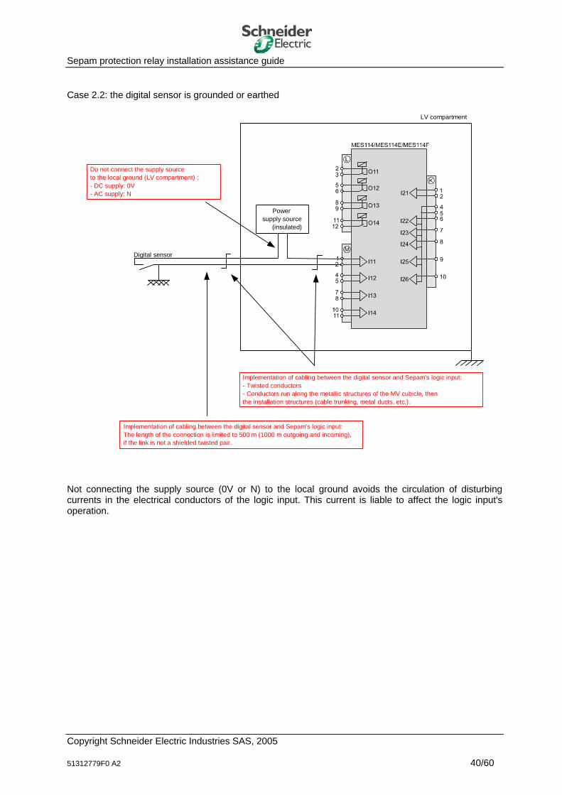
Sepam protection relay installation assistance guide Case 2.2: the digital sensor is grounded or earthed
Digital sensor
Powersupply source
(insulated)
LV compartment
Implementation of cabling between the digital sensor and Sepam's logic input: - Twisted conductors- Conductors run along the metallic structures of the MV cubicle, then the installation structures (cable trunking, metal ducts, etc.).
Do not connect the supply source to the local ground (LV compartment) : - DC supply: 0V - AC supply: N
Implementation of cabling between the digital sensor and Sepam's logic input:The length of the connection is limited to 500 m (1000 m outgoing and incoming), if the link is not a shielded twisted pair.
Not connecting the supply source (0V or N) to the local ground avoids the circulation of disturbing currents in the electrical conductors of the logic input. This current is liable to affect the logic input's operation.
Copyright Schneider Electric Industries SAS, 2005 51312779F0 A2 40/60
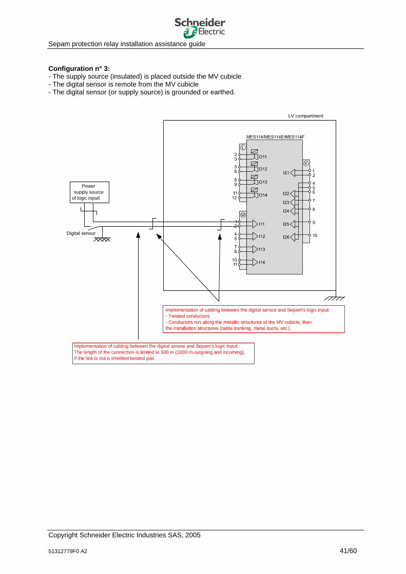
Sepam protection relay installation assistance guide Configuration n° 3: - The supply source (insulated) is placed outside the MV cubicle - The digital sensor is remote from the MV cubicle - The digital sensor (or supply source) is grounded or earthed.
Digital sensor
Power supply source
of logic inpuit
LV compartment
Implementation of cabling between the digital sensor and Sepam's logic input: - Twisted conductors- Conductors run along the metallic structures of the MV cubicle, then the installation structures (cable trunking, metal ducts, etc.).
Implementation of cabling between the digital sensor and Sepam's logic input:The length of the connection is limited to 500 m (1000 m outgoing and incoming), if the link is not a shielded twisted pair.
Copyright Schneider Electric Industries SAS, 2005 51312779F0 A2 41/60
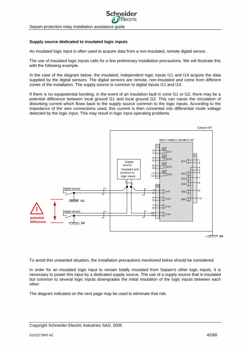
Sepam protection relay installation assistance guide Supply source dedicated to insulated logic inputs An insulated logic input is often used to acquire data from a non-insulated, remote digital sensor. The use of insulated logic inputs calls for a few preliminary installation precautions. We will illustrate this with the following example. In the case of the diagram below, the insulated, independent logic inputs I11 and I14 acquire the data supplied by the digital sensors. The digital sensors are remote, non-insulated and come from different zones of the installation. The supply source is common to digital inputs I11 and I14. If there is no equipotential bonding, in the event of an insulation fault in zone G1 or G2, there may be a potential difference between local ground G1 and local ground G2. This can cause the circulation of disturbing current which flows back to the supply source common to the logic inputs. According to the impedance of the wire connections used, this current is then converted into differential mode voltage detected by the logic input. This may result in logic input operating problems.
Digital sensor
Supplysource
insulated andcommon tologic inputs
Caisson BT
Digital sensor
potentialdifference
G1
G2
!
G0
To avoid this unwanted situation, the installation precautions mentioned below should be considered. In order for an insulated logic input to remain totally insulated from Sepam's other logic inputs, it is necessary to power this input by a dedicated supply source. The use of a supply source that is insulated but common to several logic inputs downgrades the initial insulation of the logic inputs between each other. The diagram indicated on the next page may be used to eliminate that risk.
Copyright Schneider Electric Industries SAS, 2005 51312779F0 A2 42/60

Sepam protection relay installation assistance guide
Digital sensor
LV compartment
Digital sensor
Supplysource(insulated)
G1
G2
Supplysource(insulated)
G0
Copyright Schneider Electric Industries SAS, 2005 51312779F0 A2 43/60
Sepam protection relay installation assistance guide Sepam logic outputs (O1 to O4, Ox1 to Ox4) Sepam has logic outputs. All of the logic outputs are insulated. The user may freely dispose of the logic outputs or they may be assigned to a predefined application (e.g. MV circuit breaker coil control). The logic outputs consist of a dry contact supplied by a potential-free electromechanical relay. The load controlled by a logic output requires an external power supply source (DC or AC). Type of Sepam logic outputs According to the Sepam model, two types of logic outputs are available to the user: - Logic outputs dedicated to control
These outputs are used mainly to send control orders to the MV breaking device. - Logic outputs dedicated to indication
These outputs are generally used to transfer data.
Sepam model Logic outputs dedicated to control Logic outputs dedicated to indication Sepam Series 20 Yes Yes Sepam Series 40 Yes Yes Sepam Series 80 Yes Yes Sepam 2000 No distinction between logic outputs
The rated current and breaking capacity of the logic outputs dedicated to control are obviously higher than those of the logic outputs dedicated to indication. The service life of the electromechanical relays and the correct operation of Sepam depend on correct use of the logic outputs. The surfaces of the logic output relay contacts need to be cleaned. The circulation of a minimal current in the contacts is recommended to destroy the oxides that may form on the surface of the contacts. Special case of Sepam 2000: In the case of the Sepam 2000 protection relay, there is no distinction between the logic outputs dedicated to control and those dedicated to indication. The different logic outputs must be managed carefully. A Sepam 2000 logic output initially dedicated to the control of a power load should not be reused to control a low-consumption load (e.g. a Sepam relay logic input). However, the opposite is tolerated. The switching of a several Amp current destroys the thin layer of gold deposited on the electromechanical relay contacts. When the deposit is destroyed, the initial low ohmic resistance of the relay contact is no longer guaranteed and this may result in uncertain electrical contact. Cabling The conductors are held in the same strand, twisted if possible, to avoid the creation of cabling loops.
Copyright Schneider Electric Industries SAS, 2005 51312779F0 A2 44/60
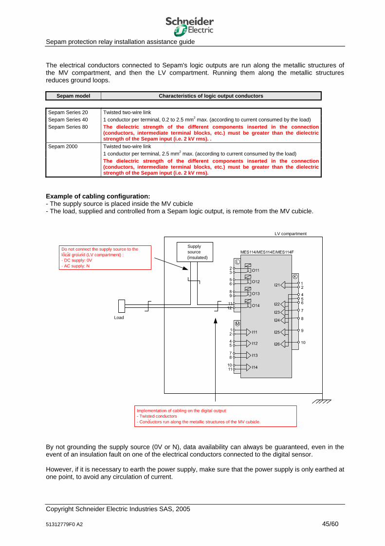
Sepam protection relay installation assistance guide The electrical conductors connected to Sepam's logic outputs are run along the metallic structures of the MV compartment, and then the LV compartment. Running them along the metallic structures reduces ground loops.
Sepam model Characteristics of logic output conductors Sepam Series 20 Twisted two-wire link Sepam Series 40 1 conductor per terminal, 0.2 to 2.5 mm2 max. (according to current consumed by the load) Sepam Series 80 The dielectric strength of the different components inserted in the connection
(conductors, intermediate terminal blocks, etc.) must be greater than the dielectric strength of the Sepam input (i.e. 2 kV rms). .
Sepam 2000 Twisted two-wire link 1 conductor per terminal, 2.5 mm2 max. (according to current consumed by the load) The dielectric strength of the different components inserted in the connection
(conductors, intermediate terminal blocks, etc.) must be greater than the dielectric strength of the Sepam input (i.e. 2 kV rms).
Example of cabling configuration: - The supply source is placed inside the MV cubicle - The load, supplied and controlled from a Sepam logic output, is remote from the MV cubicle.
Supplysource(insulated)
LV compartment
Load
Do not connect the supply source to the d’alimentationlocal ground (LV compartment) : - DC supply: 0V - AC supply: N
Implementation of cabling on the digital output:- Twisted conductors torsadés- Conductors run along the metallic structures of the MV cubicle.
By not grounding the supply source (0V or N), data availability can always be guaranteed, even in the event of an insulation fault on one of the electrical conductors connected to the digital sensor. However, if it is necessary to earth the power supply, make sure that the power supply is only earthed at one point, to avoid any circulation of current.
Copyright Schneider Electric Industries SAS, 2005 51312779F0 A2 45/60
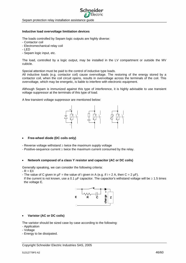
Sepam protection relay installation assistance guide Inductive load overvoltage limitiation devices The loads controlled by Sepam logic outputs are highly diverse: - Contactor coil - Electromechanical relay coil - LED - Sepam logic input, etc. The load, controlled by a logic output, may be installed in the LV compartment or outside the MV cubicle. Special attention must be paid to the control of inductive type loads. All inductive loads (e.g. contactor coil) cause overvoltage. The restoring of the energy stored by a contactor coil, when the coil circuit opens, results in overvoltage across the terminals of the coil. This overvoltage, which may be energetic, is liable to interfere with electronic equipment. Although Sepam is immunized against this type of interference, it is highly advisable to use transient voltage suppressor at the terminals of this type of load. A few transient voltage suppressor are mentioned below:
+
-
• Free-wheel diode (DC coils only) - Reverse voltage withstand ≥ twice the maximum supply voltage - Positive-sequence current ≥ twice the maximum current consumed by the relay. • Network composed of a class Y resistor and capacitor (AC or DC coils) Generally speaking, we can consider the following criteria: - R = E/i - The value of C given in µF = the value of i given in A (e.g. if i = 2 A, then C = 2 µF).
If the current is not known, use a 0.1 µF capacitor. The capacitor's withstand voltage will be ≥ 1.5 times the voltage E.
char
geE
i
ZR C
• Varistor (AC or DC coils) The varistor should be sized case by case according to the following: - Application - Voltage - Energy to be dissipated.
Copyright Schneider Electric Industries SAS, 2005 51312779F0 A2 46/60
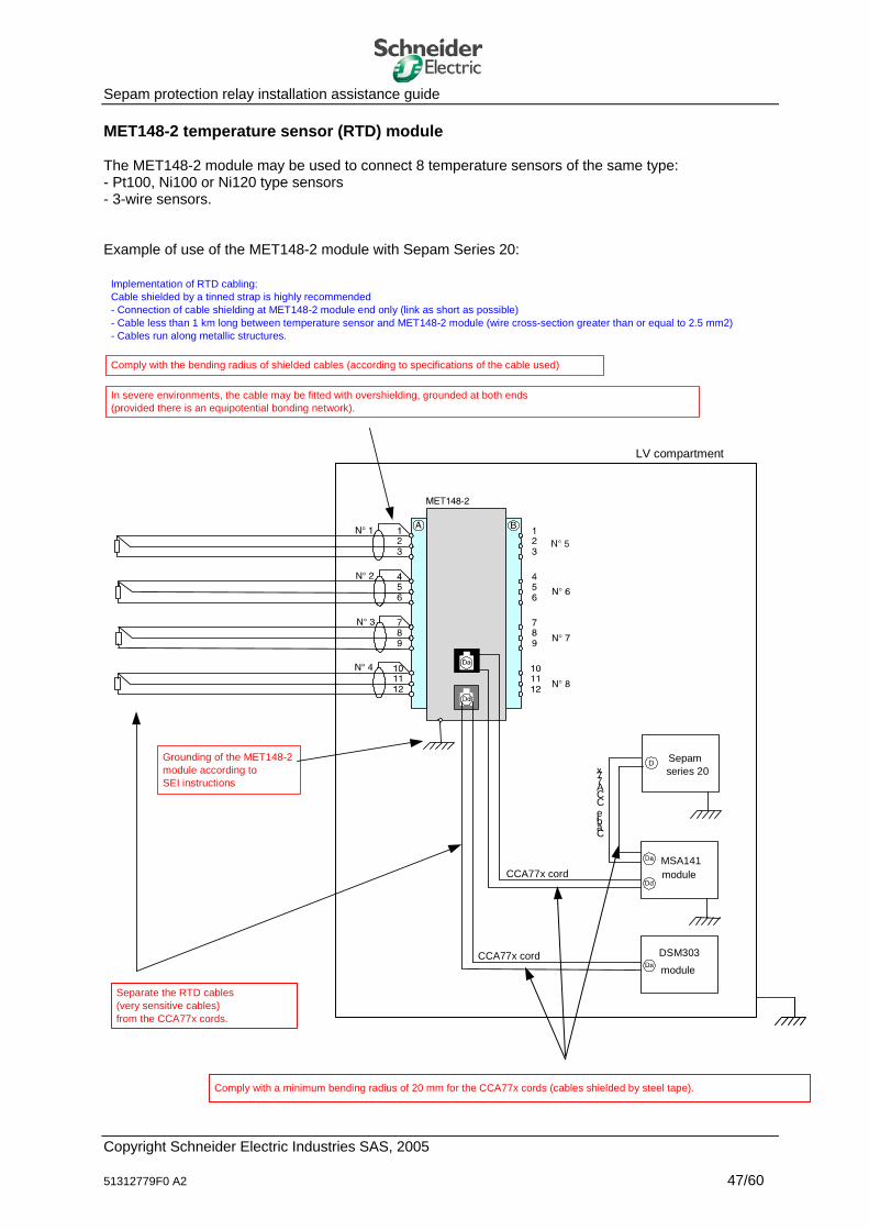
Sepam protection relay installation assistance guide MET148-2 temperature sensor (RTD) module The MET148-2 module may be used to connect 8 temperature sensors of the same type: - Pt100, Ni100 or Ni120 type sensors - 3-wire sensors. Example of use of the MET148-2 module with Sepam Series 20:
module MSA141
CCA77x cord
module DSM303 CCA77x cord
LV compartment
Separate the RTD cables (very sensitive cables) from the CCA77x cords.
Comply with a minimum bending radius of 20 mm for the CCA77x cords (cables shielded by steel tape).
Grounding of the MET148-2 module according toSEI instructions
Implementation of RTD cabling:Cable shielded by a tinned strap is highly recommended- Connection of cable shielding at MET148-2 module end only (link as short as possible)- Cable less than 1 km long between temperature sensor and MET148-2 module (wire cross-section greater than or equal to 2.5 mm2)- Cables run along metallic structures.
Sepam series 20
CâbleCCA77x
In severe environments, the cable may be fitted with overshielding, grounded at both ends(provided there is an equipotential bonding network).
D
Comply with the bending radius of shielded cables (according to specifications of the cable used)
Copyright Schneider Electric Industries SAS, 2005 51312779F0 A2 47/60
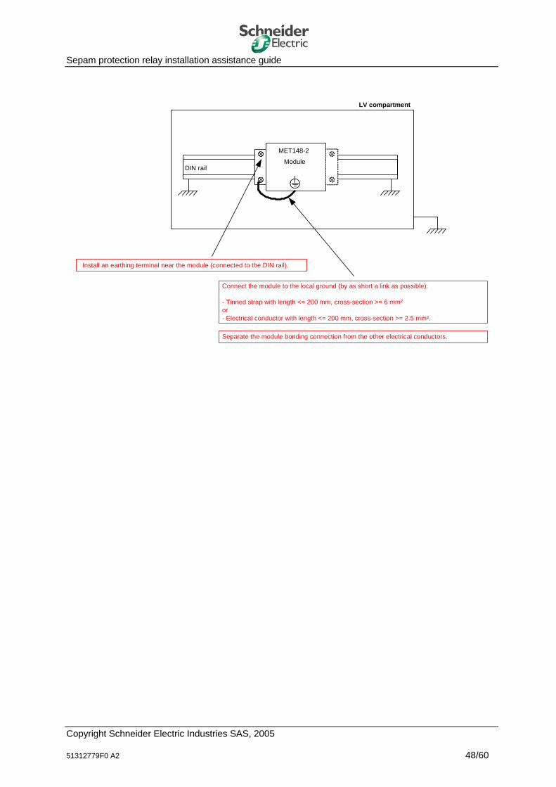
Sepam protection relay installation assistance guide
LV compartment
Install an earthing terminal near the module (connected to the DIN rail).
Module
MET148-2
DIN rail
Connect the module to the local ground (by as short a link as possible):
- Tinned strap with length <= 200 mm, cross-section >= 6 mm² or - Electrical conductor with length <= 200 mm, cross-section >= 2.5 mm².
Separate the module bonding connection from the other electrical conductors.
Copyright Schneider Electric Industries SAS, 2005 51312779F0 A2 48/60
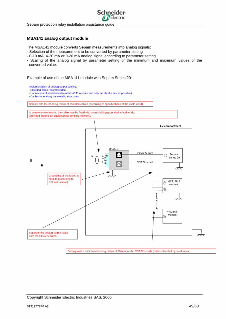
Sepam protection relay installation assistance guide MSA141 analog output module The MSA141 module converts Sepam measurements into analog signals: - Selection of the measurement to be converted by parameter setting - 0-10 mA, 4-20 mA or 0-20 mA analog signal according to parameter setting - Scaling of the analog signal by parameter setting of the minimum and maximum values of the
converted value. Example of use of the MSA141 module with Sepam Series 20:
module MET148-2
CCA77x cord
module DSM303
CCA77x cord
LV compartment
Separate the analog output cablefrom the CCA77x cords.
Comply with a minimum bending radius of 20 mm for the CCA77x cords (cables shielded by steel tape).
Comply with the bending radius of shielded cables (according to specifications of the cable used)
Implementation of analog output cabling: - Shielded cable recommended - Connection of shielded cable at MSA141 module end only (as short a link as possible)- Cables rune along the metallic structures.
In severe environments, the cable may be fitted with overshielding grounded at both ends.(provided there is an equipotential bonding network).
Sepam series 20
CâbleCCA77x
Grounding of the MSA141 module (according to SEI instructions)
D
Copyright Schneider Electric Industries SAS, 2005 51312779F0 A2 49/60
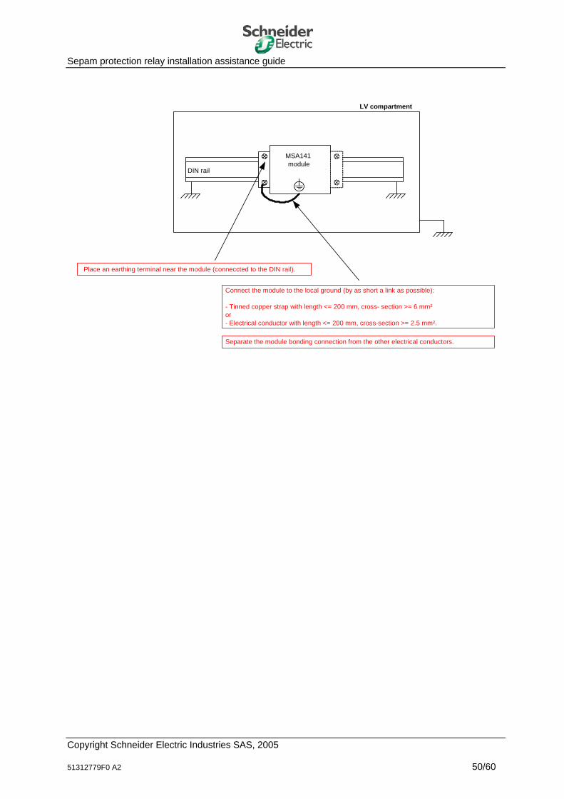
Sepam protection relay installation assistance guide
LV compartment
Place an earthing terminal near the module (conneccted to the DIN rail).
moduleMSA141
DIN rail
Connect the module to the local ground (by as short a link as possible):
- Tinned copper strap with length <= 200 mm, cross- section >= 6 mm² or - Electrical conductor with length <= 200 mm, cross-section >= 2.5 mm².
Separate the module bonding connection from the other electrical conductors.
Copyright Schneider Electric Industries SAS, 2005 51312779F0 A2 50/60
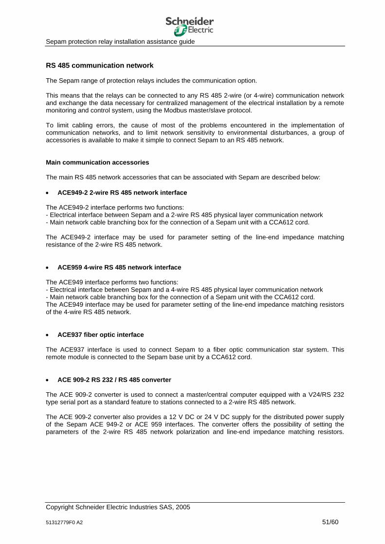
Sepam protection relay installation assistance guide RS 485 communication network The Sepam range of protection relays includes the communication option. This means that the relays can be connected to any RS 485 2-wire (or 4-wire) communication network and exchange the data necessary for centralized management of the electrical installation by a remote monitoring and control system, using the Modbus master/slave protocol. To limit cabling errors, the cause of most of the problems encountered in the implementation of communication networks, and to limit network sensitivity to environmental disturbances, a group of accessories is available to make it simple to connect Sepam to an RS 485 network. Main communication accessories The main RS 485 network accessories that can be associated with Sepam are described below: • ACE949-2 2-wire RS 485 network interface The ACE949-2 interface performs two functions: - Electrical interface between Sepam and a 2-wire RS 485 physical layer communication network - Main network cable branching box for the connection of a Sepam unit with a CCA612 cord. The ACE949-2 interface may be used for parameter setting of the line-end impedance matching resistance of the 2-wire RS 485 network. • ACE959 4-wire RS 485 network interface The ACE949 interface performs two functions: - Electrical interface between Sepam and a 4-wire RS 485 physical layer communication network - Main network cable branching box for the connection of a Sepam unit with the CCA612 cord. The ACE949 interface may be used for parameter setting of the line-end impedance matching resistors of the 4-wire RS 485 network. • ACE937 fiber optic interface The ACE937 interface is used to connect Sepam to a fiber optic communication star system. This remote module is connected to the Sepam base unit by a CCA612 cord. • ACE 909-2 RS 232 / RS 485 converter The ACE 909-2 converter is used to connect a master/central computer equipped with a V24/RS 232 type serial port as a standard feature to stations connected to a 2-wire RS 485 network. The ACE 909-2 converter also provides a 12 V DC or 24 V DC supply for the distributed power supply of the Sepam ACE 949-2 or ACE 959 interfaces. The converter offers the possibility of setting the parameters of the 2-wire RS 485 network polarization and line-end impedance matching resistors.
Copyright Schneider Electric Industries SAS, 2005 51312779F0 A2 51/60
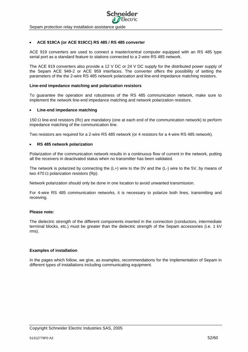
Sepam protection relay installation assistance guide • ACE 919CA (or ACE 919CC) RS 485 / RS 485 converter ACE 919 converters are used to connect a master/central computer equipped with an RS 485 type serial port as a standard feature to stations connected to a 2-wire RS 485 network. The ACE 919 converters also provide a 12 V DC or 24 V DC supply for the distributed power supply of the Sepam ACE 949-2 or ACE 959 interfaces. The converter offers the possibility of setting the parameters of the the 2-wire RS 485 network polarization and line-end impedance matching resistors. Line-end impedance matching and polarization resistors To guarantee the operation and robustness of the RS 485 communication network, make sure to implement the network line-end impedance matching and network polarization resistors. • Line-end impedance matching 150 Ω line-end resistors (Rc) are mandatory (one at each end of the communication network) to perform impedance matching of the communication line. Two resistors are required for a 2-wire RS 485 network (or 4 resistors for a 4-wire RS 485 network). • RS 485 network polarization Polarization of the communication network results in a continuous flow of current in the network, putting all the receivers in deactivated status when no transmitter has been validated. The network is polarized by connecting the (L+) wire to the 0V and the (L-) wire to the 5V, by means of two 470 Ω polarization resistors (Rp). Network polarization should only be done in one location to avoid unwanted transmission. For 4-wire RS 485 communication networks, it is necessary to polarize both lines, transmitting and receiving. Please note: The dielectric strength of the different components inserted in the connection (conductors, intermediate terminal blocks, etc.) must be greater than the dielectric strength of the Sepam accessories (i.e. 1 kV rms). Examples of installation In the pages which follow, we give, as examples, recommendations for the implementation of Sepam in different types of installations including communicating equipment.
Copyright Schneider Electric Industries SAS, 2005 51312779F0 A2 52/60
Sepam protection relay installation assistance guide Example of an installation including equipment communicating in the same building: Assumptions: - Moderately-sized electrical installation - Implementation of a 2-wire RS 485 communication network (the 12 V DC or 24 V DC distributed
supply is provided by the ACE 909-2 converter) - Remote monitoring and control of the installation.
moduleACE949-2
CCA612 cord
LV compartment
Comply with a minimum bending radius of 20 mm for theCCA612 cord.
Connect Sepam to the local ground (according to SEI instructions)
Sepam series 20 C
Connect the module to the local ground (according to SEI instructions)
Be careful of the connection of the RS485 cable shielding to the ACE949-2 module:- Grounding of shielded cable by metallic clamps provided on the module- Mechanical tightening of the clamp is sufficient to guarantee contact, but not too much to damage the RS485 cable.
C
MV cubicle
ACE909-2 module
If one of the following two conditions is met: - Equipotential bonding of the installation not guaranteed or considered insufficient- Installation TN-C earthing system arrangement Implement a backup PE cable to connect communicating equipment(16 mm2 cross-section recommended).
Other equipment
RS 232Master/
central computer
Other equipment
Connect the module to the localground (according to SEI instructions)
Guarantee grounding of the RS 485 cable shielding: - Use the SubD 9 pin connector (shielded) delivered with the ACE909-2 module
Separate the signal groups:- Make sure to separate the RS485 cable from the supply lines and logic inputs/outputs
Implementation of the RS232 cable: - Minimize the length of the RS232 cable (max. length 10m)- Make sure to separate this cable from incompatible signal groups- Use the reducing means available (metal cable trunking, etc.)
LNPE
R e s p e c te rla lo n g u e u rto ta le sp é c ifié e p o u rle ré s e a u d e c o m m u n ic a tio n R S 4 8 5 :
-D é p e n d a n td u n o m b re d e p ro d u its c o n n e c té s s u rR S 4 8 5
-S e lo n p ré s e n c e o u n o n d e la té lé -a lim e n ta tio n
Transform the earthing system to TN-S locally: - In particular if TN-C or IT systems are present - Use of a transformer with grounded secondary.
230 Vac
MV compartment
R S 4 8 5 + té lé -a lim e n ta tio n
R S 4 8 5 + té lé -a lim e n ta tio n
RS 485
Distributedsupply
2
2
2
2
2
2
2
2
Building 1
230 Vac
RS 232
Téléalimentation
RX
TX
L N PE
Comply with the bending radius specified for the RS485 cable used (according to the cablereference)
Copyright Schneider Electric Industries SAS, 2005 51312779F0 A2 53/60
Sepam protection relay installation assistance guide
LV compartment
ACE949-2 orACE959 moduleDIN rail
Place an earthing terminal near the module (connected to the DIN rail).
Connect the module to the local ground (by as short a link as possible):
- Tinned copper strap with length <= 200 mm, cross-section >= 6 mm² or - Electrical conductor with length <= 200 mm, cross-section >= 2.5 mm².
Separate the bonding connection for the other electrical conductors. Warning regarding the TN-C system: When the electrical installation includes a TN-C earthing system, 50 Hz currents and odd-number harmonic currents (H3, H5, etc.) circulate continually: - In the cable shielding if it is earthed at both ends - In the communication network's 0V link if it is earthed.
Copyright Schneider Electric Industries SAS, 2005 51312779F0 A2 54/60
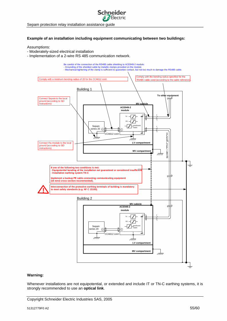
Sepam protection relay installation assistance guide Example of an installation including equipment communicating between two buildings: Assumptions: - Moderately-sized electrical installation - Implementation of a 2-wire RS 485 communication network.
moduleACE949-2
CCA612 cord
LV compartment
Comply with a minimum bending radius of 20 for the CCA612 cord.
Connect Sepam to the localground (according to SEI instructions)
Sepamseries 20 C
Connect the module to the local ground (according to SEI instructions)
Be careful of the connection of the RS485 cable shielding to ACE949-2 module:- Grounding of the shielded cable by metallic clamps provided on the module- Mechanical tightening of the clamp is sufficient to guarantee contact, but not too much to damage the RS485 cable.
Comply with the bending radius specified for the RS485 cable used (according to the cable reference).
C
MV cubicle
If one of the following two conditions is met:- Equipotential bonding of the installation not guaranteed or considered insufficient- Installation earthing system TN-C Implement a backup PE cable connecting communicating equipment(16 mm2 cross-section recommended).
MV compartment
R S 4 8 5 + té lé -a lim e n ta tio n
2
2
2
2
Building 1
Distributedsupply
RX
TX
moduleACE949-2
CCA612 cord
LV compartment
Sepamseries 20 C C
MV cubicle
MV compartment
2
2
Distributedsupply
RX
TX
To other equipment
Building 2
Interconnection of the protective earthing terminals of building is mandatoryto meet safety standards (e.g. NF C 15100).!
Warning: Whenever installations are not equipotential, or extended and include IT or TN-C earthing systems, it is strongly recommended to use an optical link.
Copyright Schneider Electric Industries SAS, 2005 51312779F0 A2 55/60
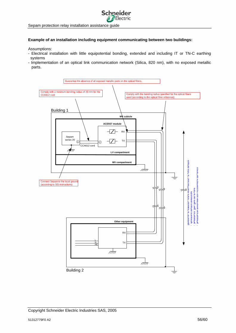
Sepam protection relay installation assistance guide Example of an installation including equipment communicating between two buildings: Assumptions: - Electrical installation with little equipotential bonding, extended and including IT or TN-C earthing
systems - Implementation of an optical link communication network (Silica, 820 nm), with no exposed metallic
parts.
ACE937 module
CCA612 cord
LV compartment
Comply with a minimum bending radius of 20 mm for theCCA612 cord
Connect Sepam to the local ground (according to SEI instructions)
Sepam series 20
C
Comply with the bending radius specified for the optical fibers used (according to the optical fiber reference).
C
Other equipment
L N PE
R e s p e c te rla lo n g u e u rto ta le s p é c ifié e p o u rla fib re o p tiq u e :
-P u is s a n c e o p tiq u e d is p o n ib le
-Atténuationmax imaledelafibre
-Atténuationsassociéesauxconnecteursdeliaison.
MV compartment
Building 1
Building 2
RX
TX
RX
TX
MV cubicle
Guarantee the absence of all exposed metallic parts on the optical fibers.
Copyright Schneider Electric Industries SAS, 2005 51312779F0 A2 56/60

Sepam protection relay installation assistance guide
Annex 1: Logical connections for "Logic discrimination" The logical connections used for logic discrimination comprise indication relay outputs (O3, O4, O12, O13 and O14 contacts) and logic inputs (Sepam relay or MES 114 module). The parameters to be taken into account to define the sizing of the connection are as follows: - Minimum operating voltage - Maximum operating current - Maximum trip threshold voltage - Minimum cable cross-section - Maximum connection length. In some cases, electromagnetic interference may affect the connection. Precautions are to be taken to minimize such effects. Calculation of the maximum theoretical length of the connection Maximum connection resistance = (minimum operating voltage - maximum trip threshold voltage) / maximum operating current With:
- Minimum operating voltage: 24 V DC – 20 % = 19.2 V - Maximum trip threshold voltage: 14 V - Maximum operating current: 3 mA
i.e. maximum connection resistance = 1.73 kΩ Maximum connection length = maximum connection resistance / resistance per meter for the minimum cross-section of the connection wire used With:
- Minimum cross-section of connection wire: 0.2 mm² - Resistance per meter for the minimum cross-section of the connection wire used: 86.4 mΩ/m
i.e. maximum connection length = 10,000 m outgoing and incoming These theoretical results are not realistic since it necessary to take into account environment and installation conditions which were assumed here to be perfect. In addition, the following factors must be taken into account: When there is a change of status, the signal propagation time depends on the length of the line, Long lines are highly capacitive.
For point , the propagation time for a 5000 m line is 33 µs (propagation time of 6.6 ns/m). That means that the reading of the change of status must take place with a longer time. Generally speaking, a factor greater than or equal to 3 is used, or a time greater than or equal to 100 µs. For point , the linear capacitance of the line with respect to the earth increases with length. The average value is in the range of 10 to 50 pF/m depending on the line running method. The capacitance for a 5000 m line in the range of 50 to 250 nF. This stray capacitance may become loaded with more or less high voltage, according to various factors such as coupling with other cables and the frequency bandwidth of coupled interference. The lower the supply voltage on the contacts, the more operating problems are caused.
Copyright Schneider Electric Industries SAS, 2005 51312779F0 A2 57/60

Sepam protection relay installation assistance guide For those reasons and to minimize operating problems, the following points are to be taken into account: - The outgoing and incoming connections should be twisted pairs to minimize the differential mode loop
surface. - The connection should be run away from all disturbing cabling. - The power supply reference should only be earthed (unless it is necessary) at one point, to avoid any
circulation of uncontrolled current (common impedance = source of EMC problems). If these conditions are not met, the length of the line must be limited to a value less than or equal to 500 m. When the running of the connection is not controlled (separation distance from disturbing cables), a shielded twisted pair must be used. In such cases, the connection shielding must be connected to the exposed conductive parts at both ends. This means that the earthing and bonding connections of the shield must be equipotentially bonded (same earthing system). This situation is not foreseeable if the Sepam and installation earthing systems are of the TN-C or TN-C-S type. In such cases, 50 Hz currents and high harmonic currents may circulate on the connection shielding and make it vulnerable, or even destroy the cable in the event of phase to earth fault. Similarly, with the IT earthing system, this may cause overvoltage problems. In such cases, surge suppressors should be provided to maintain a level that is compatible with the connection withstand (withstand of the cable, associated connectors and Sepam I/Os). Should it be impossible to master all of these parameters, only a galvanically insulated connection (galvanic insulation, fiber optic) can ensure correct operation.
Copyright Schneider Electric Industries SAS, 2005 51312779F0 A2 58/60

Sepam protection relay installation assistance guide
Annex 2: Glossary
Classification in alphabetical order. Bonding mesh Area consisting of two bonding connections (reduces the impedance of the equipotential bonding network). Common mode (also called parallel, longitudinal or asymmetric mode) Currents circulating in the same direction on all the conductors of a wire connection. Dependability The capability of an entity to fulfill one or more required functions in given conditions. The concepts of reliability, maintainability, availability and safety are associated with dependability. Differential mode (also called normal, serial or symmetric mode) Current circulating in phase opposition on two conductors of a wire connection. Downgrading (operation) Unwanted deviation in the operating characteristics of a mechanism, device or system compared to the expected characteristics. Earth electrode (NF C 15 100) Conductive part, which may be incorporated in the ground or in a particular conductive medium, such as concrete or coke, in electrical contact with the Earth. Earthing terminal (IEC 60050-195-02-31) A terminal with which an equipment item or device is fitted, and which is intended to be electrically connected to the earthing installation.
Electromagnetic Compatibility (or CEM) The capability of a mechanism, device or system to operate in its electromagnetic environment in a satisfactory way, and without producing itself any electromagnetic interference that is intolerable for everything found in that environment. Electromagnetic environment Group of existing electromagnetic phenomena in a given location. Electromagnetic interference Electromagnetic phenomenon liable to create operating problems in a mechanism, device or system, or to have a detrimental effect on living or inert matter. Equipotential bonding (NF C 15 100) Electrical bonding which puts exposed conductive parts and conductive elements at the same potential, or similar potentials.
Equipotential bonding connection Equipotential bonding of two grounds. Equipotential bonding terminal (IEC 60050-195-02-32) A terminal with which an equipment item or device is fitted, and which is intended to be electrically connected to the equipotential bonding network.
Copyright Schneider Electric Industries SAS, 2005 51312779F0 A2 59/60

Sepam protection relay installation assistance guide Failure Ceasing of an entity's capability to perform a required function. Functional earthing conductor (IEC 60050-195-02-15) Earthing conductor used for functional earthing. Ground (NF C 15 100) Conductive part of equipment, liable to be touched, and which is not energized, but may become energized when the main insulation is faulty.
Ground loop area Area consisting of an active conductor and a ground. Immunity (to interference) The capability of a mechanism, device or system to operate without downgraded quality in the presence of electromagnetic interference. Installation (EMC context) Combination of devices, components and systems assembled and/or mounted in a given zone. Level (of a quantity) Value of a quantity evaluated in a specified way. Level of immunity Maximum level of electromagnetic interference of a given type that can have an effect on a mechanism, device or system in a specified way, without downgrading operation. Local earth (NF C 15 100) Part of the Earth in electrical contact with an earth electrode, the electrical potential of which is not necessarily equal to zero. PE protective conductor (NF C 15 100) Conductor specified in certain protection measures against electric shocks and designed to be connected electrically to some of the following parts: - Grounds - Conductive elements - Main earthing terminal - Earth electrode - Supply point connected to the earth or to an artificial neutral point. Protective earthing (IEC 60050-195-01-11) Action of earthing one or more points in a system, installation or device for safety purposes.
Susceptibility (electromagnetic) The incapability of a mechanism, device or system to operate without downgrading in the presence of electromagnetic interference. N.B. Susceptibility may be interpreted as a lack of immunity. System (EMC context) Combination of devices making up a unique functional unit, designed to be installed and used to perform one or more specific tasks.
Copyright Schneider Electric Industries SAS, 2005 51312779F0 A2 60/60