Embed Size (px)
Citation preview
Steel Products
Microwave Planners GuideStructural Support Products
Midwest Underground Technology, Inc.
MUTI AND COMMSCOPE
MUTI and Commscope have joined forces to address client concerns on the installation and overall system perfor-mance of their microwave dishes. To address these issues, we have compiled this Microwave Solutions Catalog.
From the data provided to us by our clients, it is clear that many of the system performance issues are due to the incorrect mount being used or the improper installation of a mount.
Our intent is to allow the groups responsible for planning a microwave deployment to properly specify a mount that meets the TIA and manufacturer's loading requirements. This has been identified as the single greatest issue to the suc-cessful deployment of microwave systems. Many times this occurs because the contractor is left to determine which mount to use and how it should be installed. In turn this catalog will allow the engineers and microwave planners the ability to specify the mount part numbers prior to contractors bidding the projects.
In order to achieve a quality product for the owner, contractors shall plan properly to insure that the installation is done with Structure, Safety, and System in mind. This planning will also take into account the long term maintenance of the site.
Owners hire contractors as their experts in the field. As experts, the contractors should be delivering the highest quality installs for the owners. If an issue with an install is noted in the planning phase, the contractor should communicate this issue to the owner in order to minimize the owner's long term costs and exposure.
This catalog will also serve as a secondary reference manual. We endeavor to add important tools throughout the catalog which will allow planners, engineers, and installers to have a better understanding of the requirements for a suc-cessful installation with minimal maintenance expense.
About MUTI MUTI specializes in communications tower erection, multi-site maintenance, full site construction, and horizontal directional drilling, with extensive experience in the installation of tower foundations both mat and drilled shaft types, instal-lation of access roads and site clearing, all types of excavation, tower erection, multi-site tower maintenance/inspection, installation of full grounding systems, and underground directional drilling.
About Commscope Here at Commscope, we embrace our role as a trusted resource, partner, and facilitator. We create the infrastruc-ture that connects the world and evolves with every advance in technology. By investing all of our capabilities, resources, relationships, and products into your toughest challenges, we continue our long history of solving problems together-paving the way for new ideas and fresh ways of thinking. We're a trusted resource and partner around the world because we're invested in you: your people, your networks, your success. It inspires us to build relationships and infrastructure...connect people and technologies across protocols, oceans, and time zones...and share what we learn along the way. We'll never stop connecting and evolving networks for the business of life at home, at work, and on the go. This is our promise to you. This is Commscope.
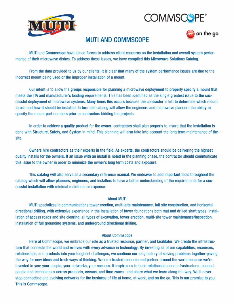
Table of Contents
Tower Mounts . . . . . . . . . . . . . . . . . . . . . . . . . . . . . . . . . . . . . . . . . . . . . . . . . . . . . . . . . . . . . . . . . . . . . . . . . . . . . . . . . . . . . . 5 Leg Mounting Solutions . . . . . . . . . . . . . . . . . . . . . . . . . . . . . . . . . . . . . . . . . . . . . . . . . . . . . . . . . . . . . . . . . . . . . . . . . . . . . 6 Application Guide . . . . . . . . . . . . . . . . . . . . . . . . . . . . . . . . . . . . . . . . . . . . . . . . . . . . . . . . . . . . . . . . . . . . . . . . . . . .10-13 Face Mounting Solutions . . . . . . . . . . . . . . . . . . . . . . . . . . . . . . . . . . . . . . . . . . . . . . . . . . . . . . . . . . . . . . . . . . . . . . . . . . . 14 Application Guide . . . . . . . . . . . . . . . . . . . . . . . . . . . . . . . . . . . . . . . . . . . . . . . . . . . . . . . . . . . . . . . . . . . . . . . . . . . .20-23
Monopole Mounts . . . . . . . . . . . . . . . . . . . . . . . . . . . . . . . . . . . . . . . . . . . . . . . . . . . . . . . . . . . . . . . . . . . . . . . . . . . . . . . . . . 27 Low Profile Chain Mounts . . . . . . . . . . . . . . . . . . . . . . . . . . . . . . . . . . . . . . . . . . . . . . . . . . . . . . . . . . . . . . . . . . . . . . . . . . 28 Light Duty Chain Mounts . . . . . . . . . . . . . . . . . . . . . . . . . . . . . . . . . . . . . . . . . . . . . . . . . . . . . . . . . . . . . . . . . . . . . . . . . . . 29 Heavy Duty Chain Mounts . . . . . . . . . . . . . . . . . . . . . . . . . . . . . . . . . . . . . . . . . . . . . . . . . . . . . . . . . . . . . . . . . . . . . . . . . . 30 Microwave Components. . . . . . . . . . . . . . . . . . . . . . . . . . . . . . . . . . . . . . . . . . . . . . . . . . . . . . . . . . . . . . . . . . . . . . . . . . . . 31 Application Guide . . . . . . . . . . . . . . . . . . . . . . . . . . . . . . . . . . . . . . . . . . . . . . . . . . . . . . . . . . . . . . . . . . . . . . . . . . . .32-36 Customs . . . . . . . . . . . . . . . . . . . . . . . . . . . . . . . . . . . . . . . . . . . . . . . . . . . . . . . . . . . . . . . . . . . . . . . . . . . . . . . . . . . . 34
Roof-top Mounts . . . . . . . . . . . . . . . . . . . . . . . . . . . . . . . . . . . . . . . . . . . . . . . . . . . . . . . . . . . . . . . . . . . . . . . . . . . . . . . . . . . 35 Roof Frames . . . . . . . . . . . . . . . . . . . . . . . . . . . . . . . . . . . . . . . . . . . . . . . . . . . . . . . . . . . . . . . . . . . . . . . . . . . . . . . . . . . . 36 Mounting Components. . . . . . . . . . . . . . . . . . . . . . . . . . . . . . . . . . . . . . . . . . . . . . . . . . . . . . . . . . . . . . . . . . . . . . . . . . . . . 38
Waveguide . . . . . . . . . . . . . . . . . . . . . . . . . . . . . . . . . . . . . . . . . . . . . . . . . . . . . . . . . . . . . . . . . . . . . . . . . . . . . . . . . . . . . . . . . 4 Coaxial Support Components . . . . . . . . . . . . . . . . . . . . . . . . . . . . . . . . . . . . . . . . . . . . . . . . . . . . . . . . . . . . . . . . . . . . . . . 42 Waveguide Bridge Kits . . . . . . . . . . . . . . . . . . . . . . . . . . . . . . . . . . . . . . . . . . . . . . . . . . . . . . . . . . . . . . . . . . . . . . . . . . . . 43 Cable Ladder Kits . . . . . . . . . . . . . . . . . . . . . . . . . . . . . . . . . . . . . . . . . . . . . . . . . . . . . . . . . . . . . . . . . . . . . . . . . . . . . . . . 44
Site Related . . . . . . . . . . . . . . . . . . . . . . . . . . . . . . . . . . . . . . . . . . . . . . . . . . . . . . . . . . . . . . . . . . . . . . . . . . . . . . . . . . . . . . . 45 Microwave Ice Shields . . . . . . . . . . . . . . . . . . . . . . . . . . . . . . . . . . . . . . . . . . . . . . . . . . . . . . . . . . . . . . . . . . . . . . . . . . . . . 46 Power Telco Racks. . . . . . . . . . . . . . . . . . . . . . . . . . . . . . . . . . . . . . . . . . . . . . . . . . . . . . . . . . . . . . . . . . . . . . . . . . . . . . . . 49 Equipment Platforms . . . . . . . . . . . . . . . . . . . . . . . . . . . . . . . . . . . . . . . . . . . . . . . . . . . . . . . . . . . . . . . . . . . . . . . . . . . . . . 49 GPS Antenna Mounts. . . . . . . . . . . . . . . . . . . . . . . . . . . . . . . . . . . . . . . . . . . . . . . . . . . . . . . . . . . . . . . . . . . . . . . . . . . . . . 50
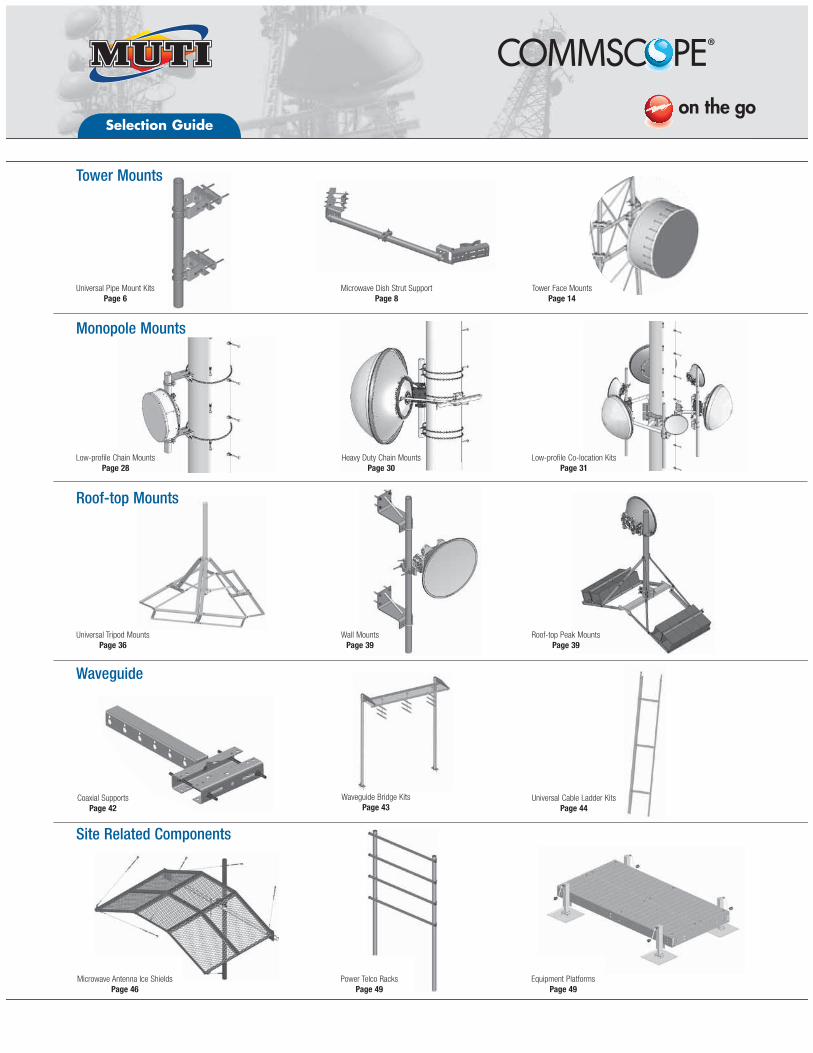
Selection Guide
Universal Cable Ladder KitsPage 44
Universal Tripod MountsPage 36
Roof-top Peak MountsPage 39
Low-profile Chain MountsPage 28
Heavy Duty Chain MountsPage 30
Low-profile Co-location KitsPage 31
Universal Pipe Mount KitsPage 6
Microwave Dish Strut SupportPage 8
Tower Mounts
Monopole Mounts
Roof-top Mounts
Waveguide
Site Related Components
Equipment PlatformsPage 49
Microwave Antenna Ice ShieldsPage 46
Waveguide Bridge KitsPage 43
Power Telco RacksPage 49
Wall MountsPage 39
Tower Face MountsPage 14
Coaxial SupportsPage 42
TOW
ER
MO
UN
TSTO
WE
R M
OU
NTS
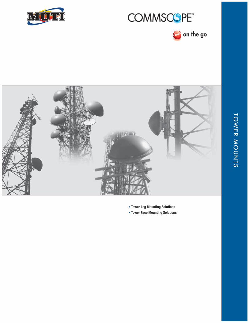
Tower Leg Mounting Solutions
Tower Face Mounting Solutions
Tower Mounts
6
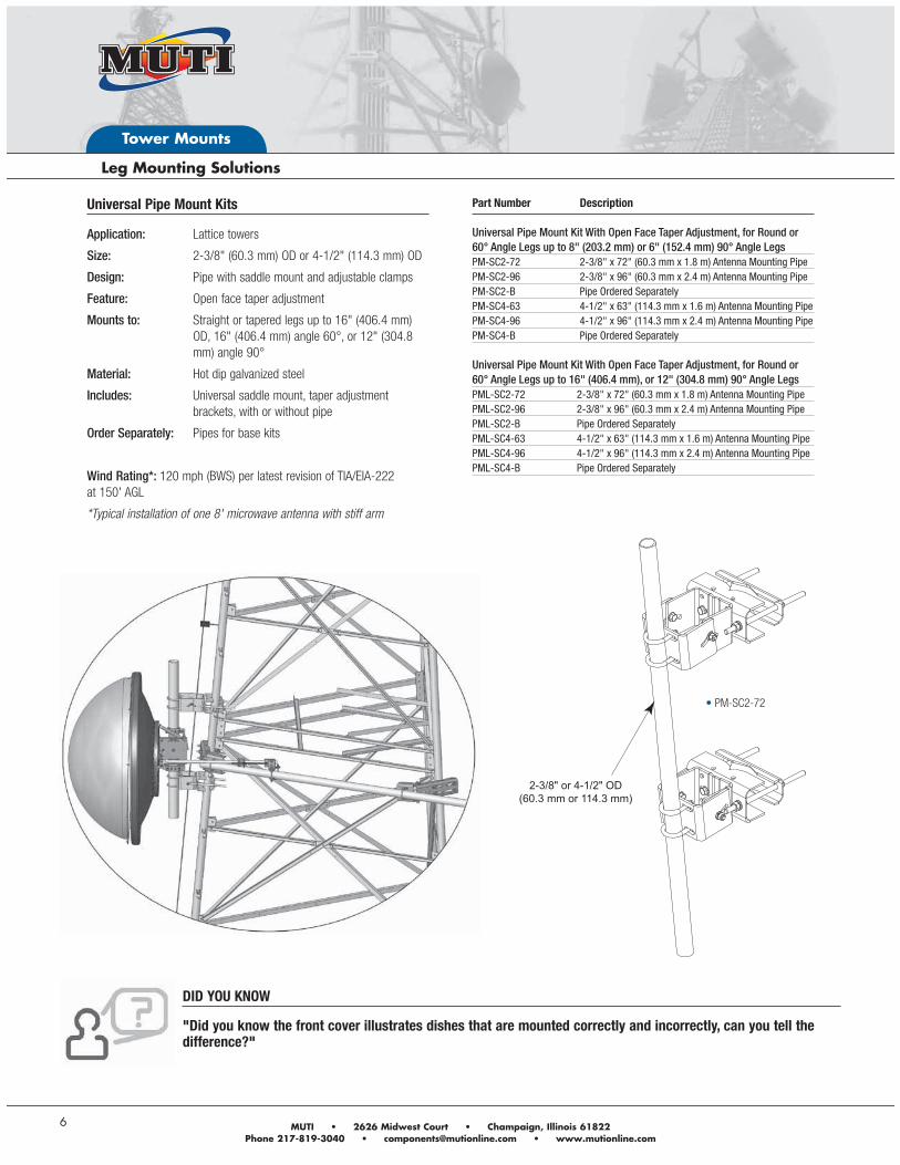
Universal Pipe Mount Kits
Application: Lattice towers
Size: 2-3/8" (60.3 mm) OD or 4-1/2" (114.3 mm) OD
Design: Pipe with saddle mount and adjustable clamps
Feature: Open face taper adjustment
Mounts to: Straight or tapered legs up to 16" (406.4 mm) OD, 16" (406.4 mm) angle 60°, or 12" (304.8 mm) angle 90°
Material: Hot dip galvanized steel
Includes: Universal saddle mount, taper adjustment brackets, with or without pipe
Order Separately: Pipes for base kits
Wind Rating*: 120 mph (BWS) per latest revision of TIA/EIA-222 at 150' AGL
*Typical installation of one 8' microwave antenna with stiff arm
Part Number Description Universal Pipe Mount Kit With Open Face Taper Adjustment, for Round or 60° Angle Legs up to 8" (203.2 mm) or 6" (152.4 mm) 90° Angle LegsPM-SC2-72 2-3/8" x 72" (60.3 mm x 1.8 m) Antenna Mounting PipePM-SC2-96 2-3/8" x 96" (60.3 mm x 2.4 m) Antenna Mounting PipePM-SC2-B Pipe Ordered SeparatelyPM-SC4-63 4-1/2" x 63" (114.3 mm x 1.6 m) Antenna Mounting PipePM-SC4-96 4-1/2" x 96" (114.3 mm x 2.4 m) Antenna Mounting PipePM-SC4-B Pipe Ordered Separately Universal Pipe Mount Kit With Open Face Taper Adjustment, for Round or 60° Angle Legs up to 16" (406.4 mm), or 12" (304.8 mm) 90° Angle LegsPML-SC2-72 2-3/8" x 72" (60.3 mm x 1.8 m) Antenna Mounting PipePML-SC2-96 2-3/8" x 96" (60.3 mm x 2.4 m) Antenna Mounting PipePML-SC2-B Pipe Ordered SeparatelyPML-SC4-63 4-1/2" x 63" (114.3 mm x 1.6 m) Antenna Mounting PipePML-SC4-96 4-1/2" x 96" (114.3 mm x 2.4 m) Antenna Mounting PipePML-SC4-B Pipe Ordered Separately
2-3/8" or 4-1/2" OD(60.3 mm or 114.3 mm)
PM-SC2-72
DID YOU KNOW
"Did you know the front cover illustrates dishes that are mounted correctly and incorrectly, can you tell the difference?"
Andrew Solutions www.commscope.com/andrew
Tower Mounts
7
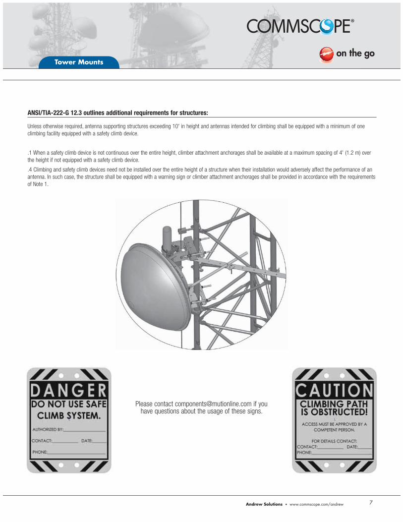
ANSI/TIA-222-G 12.3 outlines additional requirements for structures:
Unless otherwise required, antenna supporting structures exceeding 10' in height and antennas intended for climbing shall be equipped with a minimum of one climbing facility equipped with a safety climb device.
.1 When a safety climb device is not continuous over the entire height, climber attachment anchorages shall be available at a maximum spacing of 4' (1.2 m) over the height if not equipped with a safety climb device.
.4 Climbing and safety climb devices need not be installed over the entire height of a structure when their installation would adversely affect the performance of an antenna. In such case, the structure shall be equipped with a warning sign or climber attachment anchorages shall be provided in accordance with the requirements of Note 1.
Please contact [email protected] if you have questions about the usage of these signs.
Tower Mounts
8
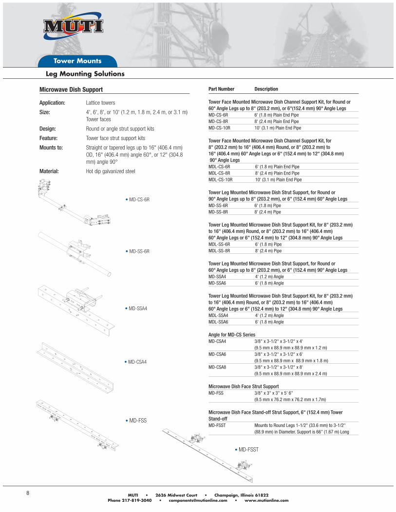
Part Number Description Tower Face Mounted Microwave Dish Channel Support Kit, for Round or 60° Angle Legs up to 8" (203.2 mm), or 6"(152.4 mm) 90° Angle LegsMD-CS-6R 6' (1.8 m) Plain End PipeMD-CS-8R 8' (2.4 m) Plain End PipeMD-CS-10R 10' (3.1 m) Plain End Pipe Tower Face Mounted Microwave Dish Channel Support Kit, for 8" (203.2 mm) to 16" (406.4 mm) Round, or 8" (203.2 mm) to 16" (406.4 mm) 60° Angle Legs or 6" (152.4 mm) to 12" (304.8 mm) 90° Angle LegsMDL-CS-6R 6' (1.8 m) Plain End PipeMDL-CS-8R 8' (2.4 m) Plain End PipeMDL-CS-10R 10' (3.1 m) Plain End Pipe Tower Leg Mounted Microwave Dish Strut Support, for Round or 90° Angle Legs up to 8" (203.2 mm), or 6" (152.4 mm) 60° Angle LegsMD-SS-6R 6' (1.8 m) Pipe MD-SS-8R 8' (2.4 m) Pipe Tower Leg Mounted Microwave Dish Strut Support Kit, for 8" (203.2 mm) to 16" (406.4 mm) Round, or 8" (203.2 mm) to 16" (406.4 mm) 60° Angle Legs or 6" (152.4 mm) to 12" (304.8 mm) 90° Angle LegsMDL-SS-6R 6' (1.8 m) PipeMDL-SS-8R 8' (2.4 m) Pipe Tower Leg Mounted Microwave Dish Strut Support, for Round or 60° Angle Legs up to 8" (203.2 mm), or 6" (152.4 mm) 90° Angle LegsMD-SSA4 4' (1.2 m) AngleMD-SSA6 6' (1.8 m) Angle Tower Leg Mounted Microwave Dish Strut Support Kit, for 8" (203.2 mm) to 16" (406.4 mm) Round, or 8" (203.2 mm) to 16" (406.4 mm) 60° Angle Legs or 6" (152.4 mm) to 12" (304.8 mm) 90° Angle LegsMDL-SSA4 4' (1.2 m) Angle MDL-SSA6 6' (1.8 m) Angle Angle for MD-CS SeriesMD-CSA4 3/8" x 3-1/2" x 3-1/2" x 4' (9.5 mm x 88.9 mm x 88.9 mm x 1.2 m)MD-CSA6 3/8" x 3-1/2" x 3-1/2" x 6' (9.5 mm x 88.9 mm x 88.9 mm x 1.8 m)MD-CSA8 3/8" x 3-1/2" x 3-1/2" x 8' (9.5 mm x 88.9 mm x 88.9 mm x 2.4 m) Microwave Dish Face Strut SupportMD-FSS 3/8" x 3" x 3" x 5' 6" (9.5 mm x 76.2 mm x 76.2 mm x 1.7m) Microwave Dish Face Stand-off Strut Support, 6" (152.4 mm) Tower Stand-offMD-FSST Mounts to Round Legs 1-1/2" (33.6 mm) to 3-1/2" (88.9 mm) in Diameter. Support is 66” (1.67 m) Long
Microwave Dish Support
Application: Lattice towers
Size: 4', 6', 8', or 10' (1.2 m, 1.8 m, 2.4 m, or 3.1 m) Tower faces
Design: Round or angle strut support kits
Feature: Tower face strut support kits
Mounts to: Straight or tapered legs up to 16" (406.4 mm) OD, 16" (406.4 mm) angle 60°, or 12" (304.8 mm) angle 90°
Material: Hot dip galvanized steel
MD-CS-6R
MD-SSA4
MD-CSA4
MD-SS-6R
MD-FSS
MD-FSST
Andrew Solutions www.commscope.com/andrew
Tower Mounts
9
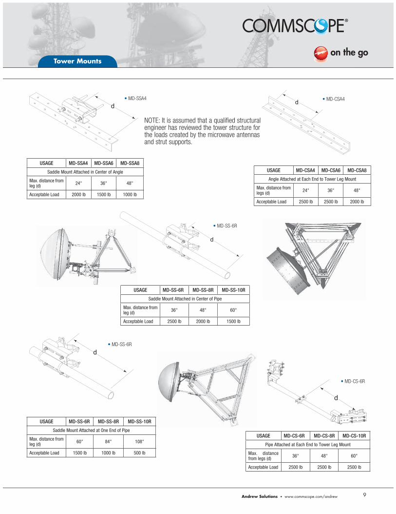
USAGE MD-SSA4 MD-SSA6 MD-SSA8
Saddle Mount Attached in Center of Angle
Max. distance from leg (d) 24" 36" 48"
Acceptable Load 2000 lb 1500 lb 1000 lb
USAGE MD-CSA4 MD-CSA6 MD-CSA8
Angle Attached at Each End to Tower Leg Mount
Max. distance from legs (d) 24" 36" 48"
Acceptable Load 2500 lb 2500 lb 2000 lb
d
USAGE MD-SS-6R MD-SS-8R MD-SS-10R
Saddle Mount Attached in Center of Pipe
Max. distance from leg (d) 36" 48" 60"
Acceptable Load 2500 lb 2000 lb 1500 lb
d
USAGE MD-SS-6R MD-SS-8R MD-SS-10R
Saddle Mount Attached at One End of Pipe
Max. distance from leg (d) 60" 84" 108"
Acceptable Load 1500 lb 1000 lb 500 lb
d
USAGE MD-CS-6R MD-CS-8R MD-CS-10R
Pipe Attached at Each End to Tower Leg Mount
Max. distance from legs (d) 36" 48" 60"
Acceptable Load 2500 lb 2500 lb 2500 lb
d
d
NOTE: It is assumed that a qualified structural engineer has reviewed the tower structure for the loads created by the microwave antennas and strut supports.
MD-SSA4 MD-CSA4
MD-SS-6R
MD-SS-6R
MD-CS-6R
Tower Mounts
10
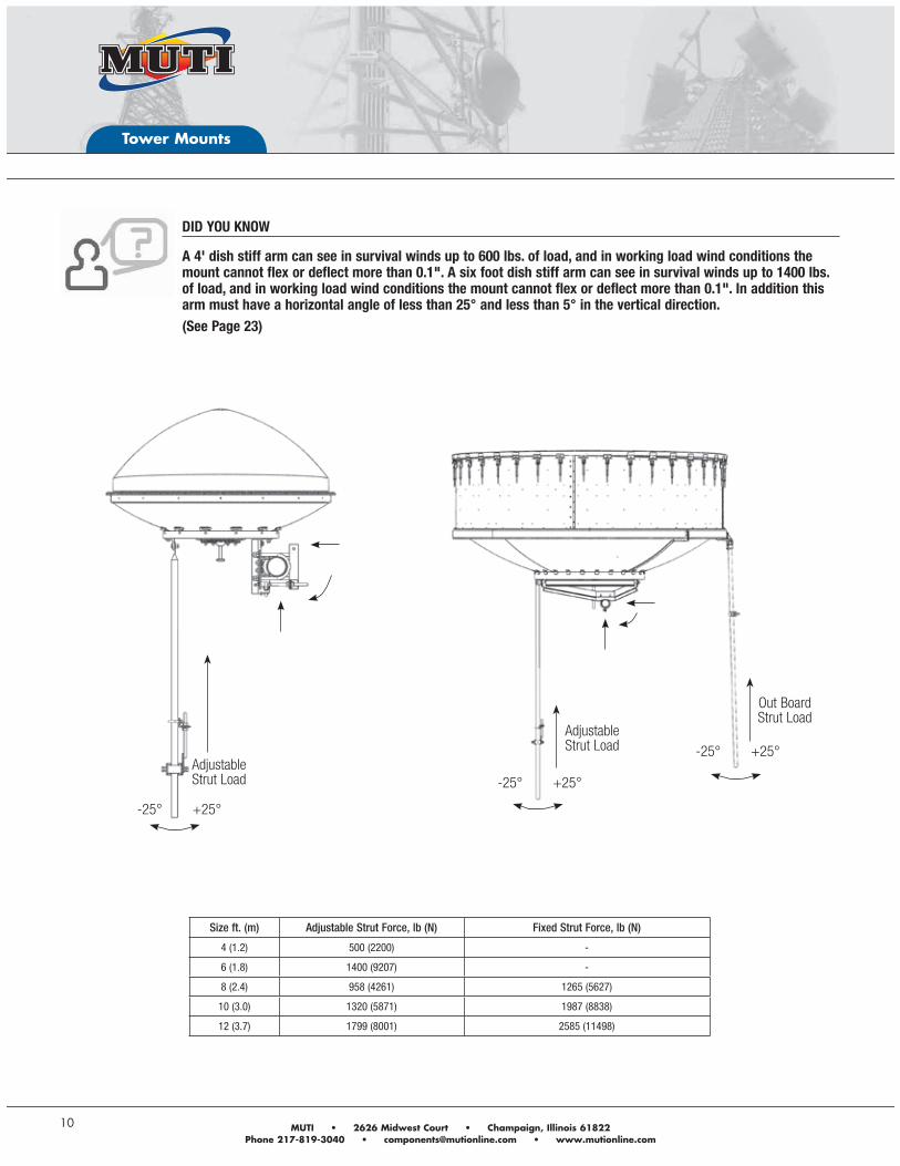
Size ft. (m) Adjustable Strut Force, lb (N) Fixed Strut Force, lb (N)
4 (1.2) 500 (2200) -
6 (1.8) 1400 (9207) -
8 (2.4) 958 (4261) 1265 (5627)
10 (3.0) 1320 (5871) 1987 (8838)
12 (3.7) 1799 (8001) 2585 (11498)
DID YOU KNOW
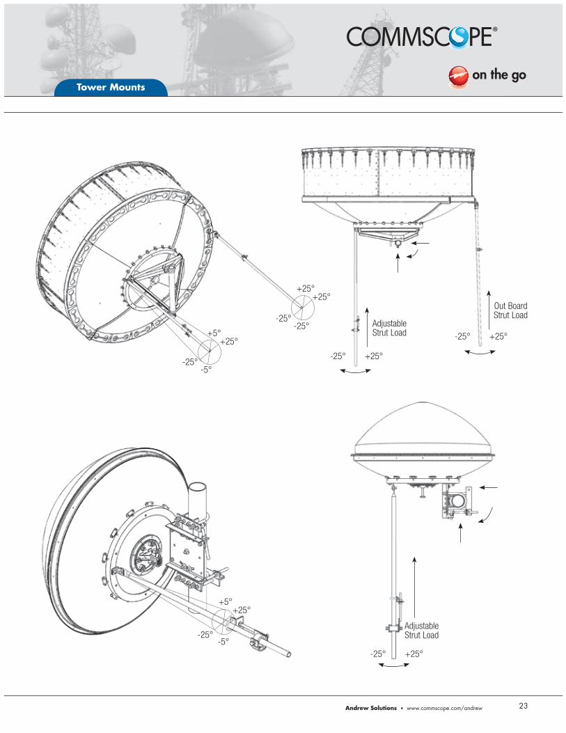
A 4' dish stiff arm can see in survival winds up to 600 lbs. of load, and in working load wind conditions the mount cannot flex or deflect more than 0.1". A six foot dish stiff arm can see in survival winds up to 1400 lbs. of load, and in working load wind conditions the mount cannot flex or deflect more than 0.1". In addition this arm must have a horizontal angle of less than 25° and less than 5° in the vertical direction. (See Page 23)
Adjustable Strut Load
+25°-25°
Out Board Strut Load
Adjustable Strut Load
+25°-25°
+25°-25°
Andrew Solutions www.commscope.com/andrew
Tower Mounts
11
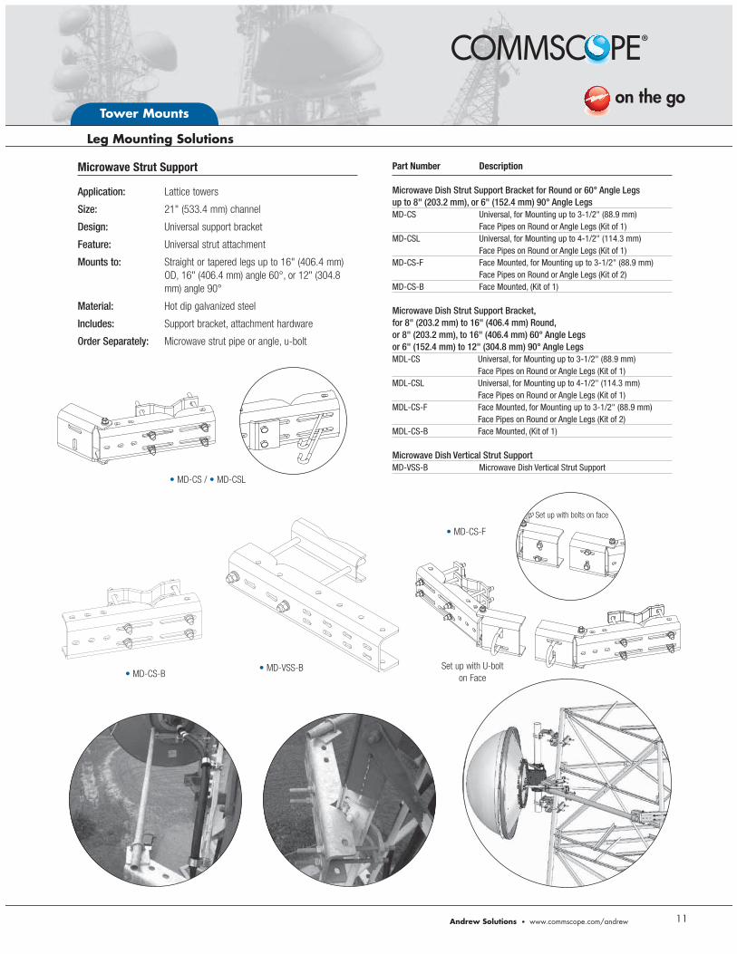
Part Number Description Microwave Dish Strut Support Bracket for Round or 60° Angle Legs up to 8" (203.2 mm), or 6" (152.4 mm) 90° Angle LegsMD-CS Universal, for Mounting up to 3-1/2" (88.9 mm) Face Pipes on Round or Angle Legs (Kit of 1)MD-CSL Universal, for Mounting up to 4-1/2" (114.3 mm) Face Pipes on Round or Angle Legs (Kit of 1)MD-CS-F Face Mounted, for Mounting up to 3-1/2" (88.9 mm) Face Pipes on Round or Angle Legs (Kit of 2)MD-CS-B Face Mounted, (Kit of 1) Microwave Dish Strut Support Bracket, for 8" (203.2 mm) to 16" (406.4 mm) Round, or 8" (203.2 mm), to 16" (406.4 mm) 60° Angle Legs or 6" (152.4 mm) to 12" (304.8 mm) 90° Angle LegsMDL-CS Universal, for Mounting up to 3-1/2" (88.9 mm) Face Pipes on Round or Angle Legs (Kit of 1)MDL-CSL Universal, for Mounting up to 4-1/2" (114.3 mm) Face Pipes on Round or Angle Legs (Kit of 1) MDL-CS-F Face Mounted, for Mounting up to 3-1/2" (88.9 mm) Face Pipes on Round or Angle Legs (Kit of 2) MDL-CS-B Face Mounted, (Kit of 1) Microwave Dish Vertical Strut SupportMD-VSS-B Microwave Dish Vertical Strut Support
Microwave Strut Support
Application: Lattice towers
Size: 21" (533.4 mm) channel
Design: Universal support bracket
Feature: Universal strut attachment
Mounts to: Straight or tapered legs up to 16" (406.4 mm) OD, 16" (406.4 mm) angle 60°, or 12" (304.8 mm) angle 90°
Material: Hot dip galvanized steel
Includes: Support bracket, attachment hardware
Order Separately: Microwave strut pipe or angle, u-bolt
MD-CS / MD-CSL
MD-CS-F
Set up with U-bolt on FaceMD-CS-B
Set up with bolts on face
MD-VSS-B
Tower Mounts
12
Key Part Number Description Page #
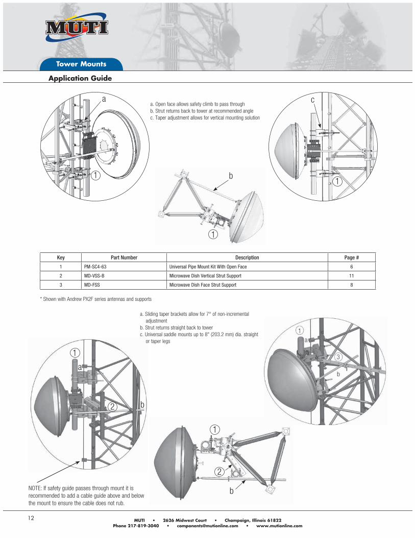
1 PM-SC4-63 Universal Pipe Mount Kit With Open Face 6
2 MD-VSS-B Microwave Dish Vertical Strut Support 11
3 MD-FSS Microwave Dish Face Strut Support 8
a. Open face allows safety climb to pass through
b. Strut returns back to tower at recommended angle
c. Taper adjustment allows for vertical mounting solution
a
1
1
b1
c
* Shown with Andrew PX2F series antennas and supports
b
1
a
2
1
b
a. Sliding taper brackets allow for 7° of non-incremental
adjustment
b. Strut returns straight back to tower
c. Universal saddle mounts up to 8" (203.2 mm) dia. straight
or taper legs
2
NOTE: If safety guide passes through mount it is recommended to add a cable guide above and below the mount to ensure the cable does not rub.
Andrew Solutions www.commscope.com/andrew
Tower Mounts
13
Key Part Number Description Page #
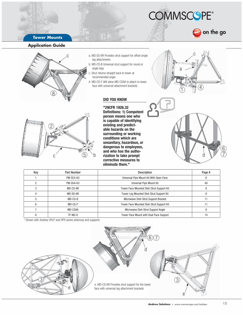
1 PM-SC4-63 Universal Pipe Mount Kit With Open Face 6
2 PM-SU4-63 Universal Pipe Mount Kit 40
3 MD-CS-6R Tower Face Mounted Dish Strut Support Kit 8
4 MD-SS-6R Tower Leg Mounted Dish Strut Support Kit 8
5 MD-CS-B Microwave Dish Strut Support Bracket 11
6 MD-CS-F Tower Face Mounted Dish Strut Support Kit 11
7 MD-CSA6 Microwave Dish Strut Support Angle 8
8 TF-M3-8 Tower Face Mount with Dual Face Support 14
a. MD-SS-6R Provides strut support for offset single
leg attachments
b. MD-CS-B Universal strut support for round or
angle legs
c. Strut returns straight back to tower at
recommended angle
d. MD-CS-F Will allow MD-CSA6 to attach to tower
face with universal attachment brackets
c
8
4
c 5
e
1
b
a
67d
d
ee. MD-CS-6R Provides strut support for the tower
face with universal leg attachment brackets
* Shown with Andrew VHLP and HPX series antennas and supports
c
3
6 7
3
2
DID YOU KNOW
"29CFR 1926.32 Definitions: 1) Competent person means one who is capable of identifying existing and predict-able hazards on the surrounding or working conditions which are unsanitary, hazardous, or dangerous to employees, and who has the autho-rization to take prompt corrective measures to eliminate them."
Tower Mounts
14
* TF-M and TFL-M Series typical applications
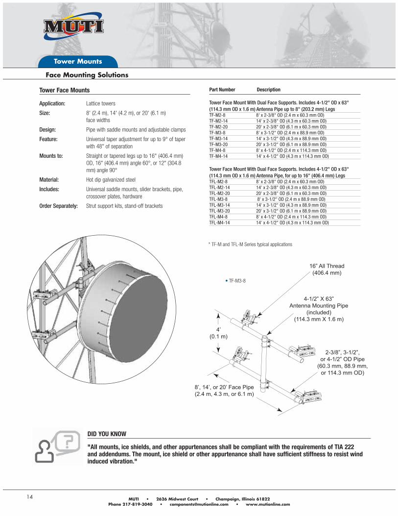
TF-M3-8
DID YOU KNOW
"All mounts, ice shields, and other appurtenances shall be compliant with the requirements of TIA 222 and addendums. The mount, ice shield or other appurtenance shall have sufficient stiffness to resist wind induced vibration."
16” All Thread(406.4 mm)
4-1/2” X 63”Antenna Mounting Pipe
(included)(114.3 mm X 1.6 m)
2-3/8”, 3-1/2”, or 4-1/2” OD Pipe
(60.3 mm, 88.9 mm, or 114.3 mm OD)
8’, 14’, or 20’ Face Pipe(2.4 m, 4.3 m, or 6.1 m)
4’(0.1 m)
Tower Face Mounts
Application: Lattice towers
Size: 8' (2.4 m), 14' (4.2 m), or 20' (6.1 m) face widths
Design: Pipe with saddle mounts and adjustable clamps
Feature: Universal taper adjustment for up to 9° of taper with 48" of separation
Mounts to: Straight or tapered legs up to 16" (406.4 mm) OD, 16" (406.4 mm) angle 60°, or 12" (304.8 mm) angle 90°
Material: Hot dip galvanized steel
Includes: Universal saddle mounts, slider brackets, pipe, crossover plates, hardware
Order Separately: Strut support kits, stand-off brackets
Part Number Description Tower Face Mount With Dual Face Supports. Includes 4-1/2" OD x 63" (114.3 mm OD x 1.6 m) Antenna Pipe up to 8" (203.2 mm) LegsTF-M2-8 8' x 2-3/8" OD (2.4 m x 60.3 mm OD) TF-M2-14 14' x 2-3/8" OD (4.3 m x 60.3 mm OD)TF-M2-20 20' x 2-3/8" OD (6.1 m x 60.3 mm OD)TF-M3-8 8' x 3-1/2" OD (2.4 m x 88.9 mm OD)TF-M3-14 14' x 3-1/2" OD (4.3 m x 88.9 mm OD)TF-M3-20 20' x 3-1/2" OD (6.1 m x 88.9 mm OD)TF-M4-8 8' x 4-1/2" OD (2.4 m x 114.3 mm OD)TF-M4-14 14' x 4-1/2" OD (4.3 m x 114.3 mm OD) Tower Face Mount With Dual Face Supports. Includes 4-1/2" OD x 63" (114.3 mm OD x 1.6 m) Antenna Pipe, for up to 16" (406.4 mm) LegsTFL-M2-8 8' x 2-3/8" OD (2.4 m x 60.3 mm OD)TFL-M2-14 14' x 2-3/8" OD (4.3 m x 60.3 mm OD)TFL-M2-20 20' x 2-3/8" OD (6.1 m x 60.3 mm OD)TFL-M3-8 8' x 3-1/2" OD (2.4 m x 88.9 mm OD)TFL-M3-14 14' x 3-1/2" OD (4.3 m x 88.9 mm OD)TFL-M3-20 20' x 3-1/2" OD (6.1 m x 88.9 mm OD)TFL-M4-8 8' x 4-1/2" OD (2.4 m x 114.3 mm OD)TFL-M4-14 14' x 4-1/2" OD (4.3 m x 114.3 mm OD)
Andrew Solutions www.commscope.com/andrew
Tower Mounts
15
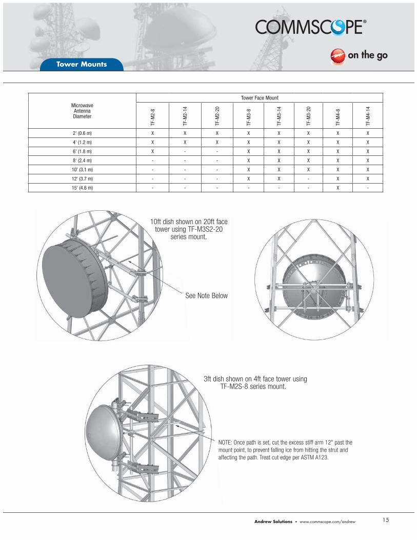
NOTE: Once path is set, cut the excess stiff arm 12" past the mount point, to prevent falling ice from hitting the strut and affecting the path. Treat cut edge per ASTM A123.
3ft dish shown on 4ft face tower using TF-M2S-8 series mount.
10ft dish shown on 20ft face tower using TF-M3S2-20
series mount.
See Note Below
MicrowaveAntennaDiameter
Tower Face Mount
TF-M
2-8
TF-M
2-14
TF-M
2-20
TF-M
3-8
TF-M
3-14
TF-M
3-20
TF-M
4-8
TF-M
4-14
2' (0.6 m) X X X X X X X X
4' (1.2 m) X X X X X X X X
6' (1.8 m) X - - X X X X X
8' (2.4 m) - - - X X X X X
10' (3.1 m) - - - X X X X X
12' (3.7 m) - - - X X - X X
15' (4.6 m) - - - - - - X -
Tower Mounts
16
TF-M3S Series
TFL-M3S2 Series
DID YOU KNOW
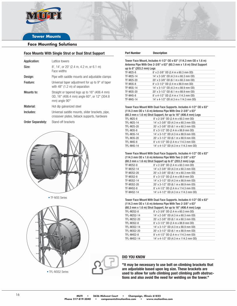
"It may be necessary to use bolt on climbing brackets that are adjustable based upon leg size. These brackets are used to allow for safe climbing past climbing path obstruc-tions and also avoid the need for welding on the tower."
Part Number Description Tower Face Mount, Includes 4-1/2" OD x 63" (114.3 mm OD x 1.6 m) Antenna Pipe With One 2-3/8" x 63" (60.3 mm x 1.6 m) Strut Support up to 8" (203.2 mm) LegsTF-M2S-8 8' x 2-3/8" OD (2.4 m x 60.3 mm OD)TF-M2S-14 14' x 2-3/8" OD (4.3 m x 60.3 mm OD)TF-M2S-20 20' x 2-3/8" OD (6.1 m x 60.3 mm OD)TF-M3S-8 8' x 3-1/2" OD (2.4 m x 88.9 mm OD)TF-M3S-14 14' x 3-1/2" OD (4.3 m x 88.9 mm OD)TF-M3S-20 20' x 3-1/2" OD (6.1 m x 88.9 mm OD)TF-M4S-8 8' x 4-1/2" OD (2.4 m x 114.3 mm OD)TF-M4S-14 14' x 4-1/2" OD (4.3 m x 114.3 mm OD) Tower Face Mount With Dual Face Supports. Includes 4-1/2" OD x 63" (114.3 mm OD x 1.6 m) Antenna Pipe With One 2-3/8" x 63" (60.3 mm x 1.6 m) Strut Support, for up to 16" (406.4 mm) LegsTFL-M2S-8 8' x 2-3/8" OD (2.4 m x 60.3 mm OD)TFL-M2S-14 14' x 2-3/8" OD (4.3 m x 60.3 mm OD)TFL-M2S-20 20' x 2-3/8" OD (6.1 m x 60.3 mm OD)TFL-M3S-8 8' x 3-1/2" OD (2.4 m x 88.9 mm OD)TFL-M3S-14 14' x 3-1/2" OD (4.3 m x 88.9 mm OD)TFL-M3S-20 20' x 3-1/2" OD (6.1 m x 88.9 mm OD)TFL-M4S-8 8' x 4-1/2" OD (2.4 m x 114.3 mm OD)TFL-M4S-14 14' x 4-1/2" OD (4.3 m x 114.3 mm OD) Tower Face Mount With Dual Face Supports. Includes 4-1/2" OD x 63" (114.3 mm OD x 1.6 m) Antenna Pipe With Two 2-3/8" x 63" (60.3 mm x 1.6 m) Strut Support up to 8" (203.2 mm) LegsTF-M2S2-8 8' x 2-3/8" OD (2.4 m x 60.3 mm OD)TF-M2S2-14 14' x 2-3/8" OD (4.3 m x 60.3 mm OD)TF-M2S2-20 20' x 2-3/8" OD (6.1 m x 60.3 mm OD)TF-M3S2-8 8' x 3-1/2" OD (2.4 m x 88.9 mm OD)TF-M3S2-14 14' x 3-1/2" OD (4.3 m x 88.9 mm OD)TF-M3S2-20 20' x 3-1/2" OD (6.1 m x 88.9 mm OD)TF-M4S2-8 8' x 4-1/2" OD (2.4 m x 114.3 mm OD)TF-M4S2-14 14' x 4-1/2" OD (4.3 m x 114.3 mm OD) Tower Face Mount With Dual Face Supports. Includes 4-1/2" OD x 63" (114.3 mm OD x 1.6 m) Antenna Pipe With Two 2-3/8" x 63" (60.3 mm x 1.6 m) Strut Support, for up to 16" (406.4 mm) LegsTFL-M2S2-8 8' x 2-3/8" OD (2.4 m x 60.3 mm OD)TFL-M2S2-14 14' x 2-3/8" OD (4.3 m x 60.3 mm OD)TFL-M2S2-20 20' x 2-3/8" OD (6.1 m x 60.3 mm OD)TFL-M3S2-8 8' x 3-1/2" OD (2.4 m x 88.9 mm OD)TFL-M3S2-14 14' x 3-1/2" OD (4.3 m x 88.9 mm OD)TFL-M3S2-20 20' x 3-1/2" OD (6.1 m x 88.9 mm OD)TFL-M4S2-8 8' x 4-1/2" OD (2.4 m x 114.3 mm OD)TFL-M4S2-14 14' x 4-1/2" OD (4.3 m x 114.3 mm OD)
Face Mounts With Single Strut or Dual Strut Support
Application: Lattice towers
Size: 8', 14', or 20' (2.4 m, 4.2 m, or 6.1 m) Face widths
Design: Pipe with saddle mounts and adjustable clamps
Feature: Universal taper adjustment for up to 9° of taper with 48" (1.2 m) of separation
Mounts to: Straight or tapered legs up to 16" (406.4 mm) OD, 16" (406.4 mm) angle 60°, or 12" (304.8 mm) angle 90°
Material: Hot dip galvanized steel
Includes: Universal saddle mounts, slider brackets, pipe, crossover plates, tieback supports, hardware
Order Separately: Stand-off brackets
Andrew Solutions www.commscope.com/andrew
Tower Mounts
17
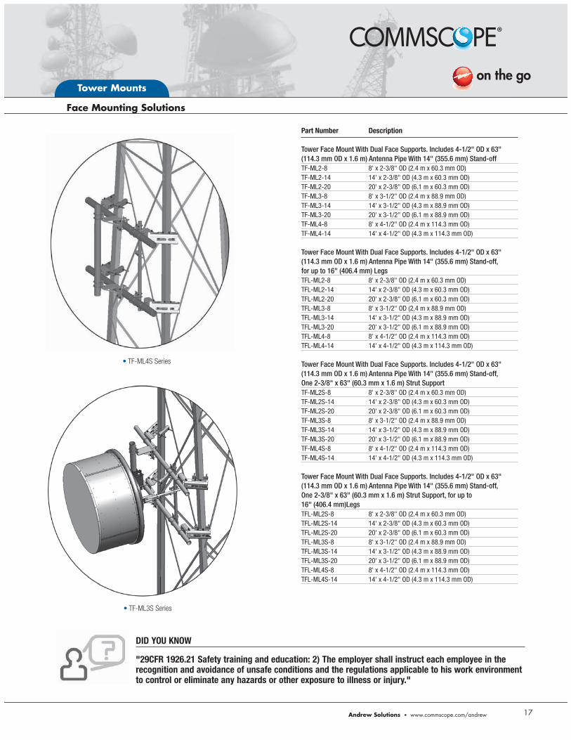
TF-ML4S Series
TF-ML3S Series
DID YOU KNOW
"29CFR 1926.21 Safety training and education: 2) The employer shall instruct each employee in the recognition and avoidance of unsafe conditions and the regulations applicable to his work environment to control or eliminate any hazards or other exposure to illness or injury."
Part Number Description Tower Face Mount With Dual Face Supports. Includes 4-1/2" OD x 63" (114.3 mm OD x 1.6 m) Antenna Pipe With 14" (355.6 mm) Stand-offTF-ML2-8 8' x 2-3/8" OD (2.4 m x 60.3 mm OD)TF-ML2-14 14' x 2-3/8" OD (4.3 m x 60.3 mm OD)TF-ML2-20 20' x 2-3/8" OD (6.1 m x 60.3 mm OD)TF-ML3-8 8' x 3-1/2" OD (2.4 m x 88.9 mm OD)TF-ML3-14 14' x 3-1/2" OD (4.3 m x 88.9 mm OD)TF-ML3-20 20' x 3-1/2" OD (6.1 m x 88.9 mm OD)TF-ML4-8 8' x 4-1/2" OD (2.4 m x 114.3 mm OD)TF-ML4-14 14' x 4-1/2" OD (4.3 m x 114.3 mm OD) Tower Face Mount With Dual Face Supports. Includes 4-1/2" OD x 63" (114.3 mm OD x 1.6 m) Antenna Pipe With 14" (355.6 mm) Stand-off, for up to 16" (406.4 mm) LegsTFL-ML2-8 8' x 2-3/8" OD (2.4 m x 60.3 mm OD)TFL-ML2-14 14' x 2-3/8" OD (4.3 m x 60.3 mm OD)TFL-ML2-20 20' x 2-3/8" OD (6.1 m x 60.3 mm OD)TFL-ML3-8 8' x 3-1/2" OD (2.4 m x 88.9 mm OD)TFL-ML3-14 14' x 3-1/2" OD (4.3 m x 88.9 mm OD)TFL-ML3-20 20' x 3-1/2" OD (6.1 m x 88.9 mm OD)TFL-ML4-8 8' x 4-1/2" OD (2.4 m x 114.3 mm OD)TFL-ML4-14 14' x 4-1/2" OD (4.3 m x 114.3 mm OD) Tower Face Mount With Dual Face Supports. Includes 4-1/2" OD x 63" (114.3 mm OD x 1.6 m) Antenna Pipe With 14" (355.6 mm) Stand-off, One 2-3/8" x 63" (60.3 mm x 1.6 m) Strut Support TF-ML2S-8 8' x 2-3/8" OD (2.4 m x 60.3 mm OD)TF-ML2S-14 14' x 2-3/8" OD (4.3 m x 60.3 mm OD)TF-ML2S-20 20' x 2-3/8" OD (6.1 m x 60.3 mm OD)TF-ML3S-8 8' x 3-1/2" OD (2.4 m x 88.9 mm OD)TF-ML3S-14 14' x 3-1/2" OD (4.3 m x 88.9 mm OD)TF-ML3S-20 20' x 3-1/2" OD (6.1 m x 88.9 mm OD)TF-ML4S-8 8' x 4-1/2" OD (2.4 m x 114.3 mm OD)TF-ML4S-14 14' x 4-1/2" OD (4.3 m x 114.3 mm OD) Tower Face Mount With Dual Face Supports. Includes 4-1/2" OD x 63" (114.3 mm OD x 1.6 m) Antenna Pipe With 14" (355.6 mm) Stand-off, One 2-3/8" x 63" (60.3 mm x 1.6 m) Strut Support, for up to 16" (406.4 mm)Legs TFL-ML2S-8 8' x 2-3/8" OD (2.4 m x 60.3 mm OD)TFL-ML2S-14 14' x 2-3/8" OD (4.3 m x 60.3 mm OD)TFL-ML2S-20 20' x 2-3/8" OD (6.1 m x 60.3 mm OD)TFL-ML3S-8 8' x 3-1/2" OD (2.4 m x 88.9 mm OD)TFL-ML3S-14 14' x 3-1/2" OD (4.3 m x 88.9 mm OD)TFL-ML3S-20 20' x 3-1/2" OD (6.1 m x 88.9 mm OD)TFL-ML4S-8 8' x 4-1/2" OD (2.4 m x 114.3 mm OD)TFL-ML4S-14 14' x 4-1/2" OD (4.3 m x 114.3 mm OD)
Tower Mounts
18
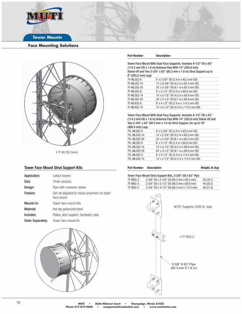
TF-ML3S2 Series
NOTE: Supports 2500 lb. load.
Part Number Description Tower Face Mount With Dual Face Supports. Includes 4-1/2" OD x 63" (114.3 mm OD x 1.6 m) Antenna Pipe With 14" (355.6 mm) Stand-off and Two 2-3/8" x 63" (60.3 mm x 1.6 m) Strut Support up to 8" (203.2 mm) LegsTF-ML2S2-8 8' x 2-3/8" OD (2.4 m x 60.3 mm OD)TF-ML2S2-14 14' x 2-3/8" OD (4.3 m x 60.3 mm OD)TF-ML2S2-20 20' x 2-3/8" OD (6.1 m x 60.3 mm OD)TF-ML3S2-8 8' x 3-1/2" OD (2.4 m x 88.9 mm OD)TF-ML3S2-14 14' x 3-1/2" OD (4.3 m x 88.9 mm OD)TF-ML3S2-20 20' x 3-1/2" OD (6.1 m x 88.9 mm OD)TF-ML4S2-8 8' x 4-1/2" OD (2.4 m x 114.3 mm OD)TF-ML4S2-14 14' x 4-1/2" OD (4.3 m x 114.3 mm OD) Tower Face Mount With Dual Face Supports. Includes 4-1/2" OD x 63" (114.3 mm OD x 1.6 m) Antenna Pipe With 14" (355.6 mm) Stand-off and Two 2-3/8" x 63" (60.3 mm x 1.6 m) Strut Support, for up to 16" (406.4 mm) LegsTFL-ML2S2-8 8' x 2-3/8" OD (2.4 m x 60.3 mm OD)TFL-ML2S2-14 14' x 2-3/8" OD (4.3 m x 60.3 mm OD)TFL-ML2S2-20 20' x 2-3/8" OD (6.1 m x 60.3 mm OD)TFL-ML3S2-8 8' x 3-1/2" OD (2.4 m x 88.9 mm OD)TFL-ML3S2-14 14' x 3-1/2" OD (4.3 m x 88.9 mm OD)TFL-ML3S2-20 20' x 3-1/2" OD (6.1 m x 88.9 mm OD)TFL-ML4S2-8 8' x 4-1/2" OD (2.4 m x 114.3 mm OD)TFL-ML4S2-14 14' x 4-1/2" OD (4.3 m x 114.3 mm OD)
Part Number Description Weight, lb (kg) Tower Face Mount Strut Support Kits, 2-3/8" OD x 63" PipeTF-MSS-2 2-3/8" OD x 2-3/8" OD (60.3 mm x 60.3 mm) 42 (19.1)TF-MSS-3 2-3/8" OD x 3-1/2" OD (60.3 mm x 88.9 mm) 44 (20.2)TF-MSS-4 2-3/8" OD x 4-1/2" OD (60.3 mm x 114.3 mm) 48 (21.8)
Tower Face Mount Strut Support Kits
Application: Lattice towers
Size: Three versions
Design: Pipe with crossover plates
Feature: Can be adjusted to mount anywhere on tower face mount
Mounts to: Tower face mount kits
Material: Hot dip galvanized steel
Includes: Plates, strut support, hardware, pipe
Order Separately: Tower face mount kit
2-3/8” X 63” Pipe(60.3 mm X 1.6 m)
TF-MSS-2
Andrew Solutions www.commscope.com/andrew
Tower Mounts
19
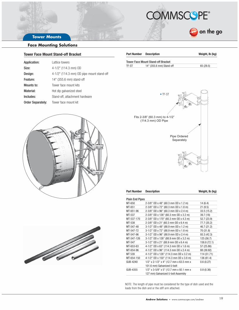
NOTE: The length of pipe must be considered for the type of dish used and the
loads from the dish and or the stiff arm attached.
Part Number Description Weight, lb (kg) Tower Face Mount Stand-off BracketTF-ST 14" (355.6 mm) Stand-off 65 (29.5)
Tower Face Mount Stand-off Bracket
Application: Lattice towers
Size: 4-1/2" (114.3 mm) OD
Design: 4-1/2" (114.3 mm) OD pipe mount stand-off
Feature: 14" (355.6 mm) stand-off
Mounts to: Tower face mount kits
Material: Hot dip galvanized steel
Includes: Stand-off, attachment hardware
Order Separately: Tower face mount kit
Pipe Ordered Separately
Fits 2-3/8” (60.3 mm) to 4-1/2” (114.3 mm) OD Pipe
Part Number Description Weight, lb (kg) Plain End PipesMT-650 2-3/8" OD x 48" (60.3 mm OD x 1.2 m) 14 (6.4)MT-651 2-3/8" OD x 72" (60.3 mm OD x 1.8 m) 21 (9.5)MT-651-96 2-3/8" OD x 96" (60.3 mm OD x 2.4 m) 33.5 (15.2)MT-537 2-3/8" OD x 126" (60.3 mm OD x 3.2 m) 39.7 (18)MT-537-170 2-3/8" OD x 170" (60.3 mm OD x 4.3 m) 52.7 (23.9)MT-538 2-3/8" OD x 21' (60.3 mm OD x 6.4 m) 77.7 (35.2)MT-547-48 3-1/2" OD x 48" (88.9 mm OD x 1.2 m) 46.7 (21.2)MT-547-72 3-1/2" OD x 72" (88.9 mm OD x 1.8 m) 70 (31.8)MT-547-96 3-1/2" OD x 96" (88.9 mm OD x 2.4 m) 93.3 (42.3)MT-547-126 3-1/2" OD x 126" (88.9 mm OD x 3.2 m) 125 (56.7)MT-547 3-1/2" OD x 21' (88.9 mm OD x 6.4 m) 158.8 (72.1)MT-653-63 4-1/2" OD x 63" (114.3 mm OD x 1.6 m) 57 (25.86)MT-654-96 4-1/2" OD x 96" (114.3 mm OD x 2.4 m) 88 (39.92)MT 539 4-1/2" OD x 126" (114.3 mm OD x 3.2 m) 114 (51.71)MT-654-150 4-1/2" OD x 150" (114.3 mm OD x 3.8 m) 136 (61.4)GUB-4240 1/2" x 2-1/2" x 4" (12.7 mm x 63.5 mm x 0.6 (0.27) 101.6 mm) Galvanized U-boltGUB-4355 1/2" x 3-5/8" x 5" (12.7 mm x 92.1 mm x 0.8 (0.36) 127 mm) Galvanized U-bolt Assembly
TF-ST
Tower Mounts
20
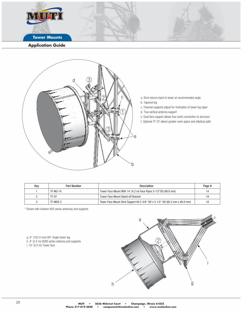
a. Strut returns back to tower at recommended angle
b. Tapered leg
c. Channel supports adjust for inclination of tower leg taper
d. True vertical antenna support
e. Dual face support allows four point connection to structure
f. Optional TF-ST allows greater work space and elliptical path
g. 6" (152.4 mm) 60° Angle tower leg
h. 8' (2.4 m) HSX8 series antenna and supports
i. 10' (3.0 m) Tower face
b
a
h g
Key Part Number Description Page #
1 TF-M3-14 Tower Face Mount With 14' (4.2 m) Face Pipes 3-1/2"OD (88.9 mm) 14
2 TF-ST Tower Face Mount Stand-off Bracket 19
3 TF-MSS-3 Tower Face Mount Strut Support Kit 2-3/8" OD x 3-1/2" OD (60.3 mm x 88.9 mm) 18
c
d
e
i
* Shown with Andrew HSX series antennas and supports
2
3
3
1
2
Andrew Solutions www.commscope.com/andrew
Tower Mounts
21
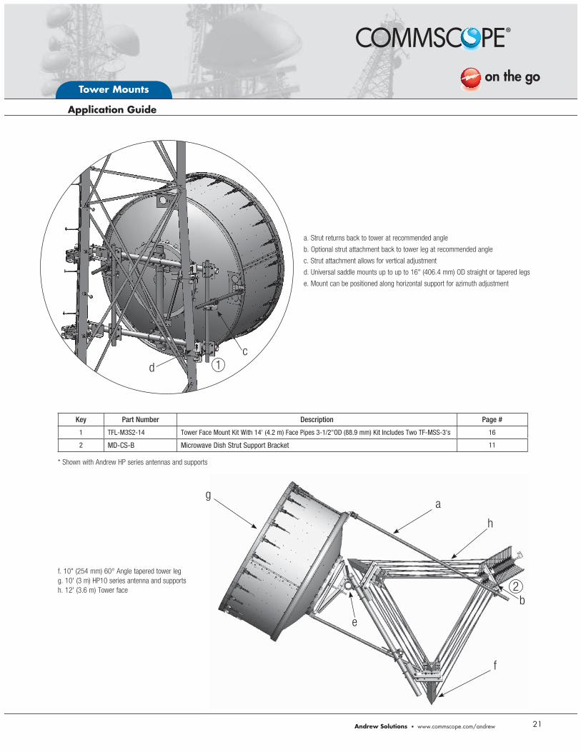
Key Part Number Description Page #
1 TFL-M3S2-14 Tower Face Mount Kit With 14' (4.2 m) Face Pipes 3-1/2"OD (88.9 mm) Kit Includes Two TF-MSS-3's 16
2 MD-CS-B Microwave Dish Strut Support Bracket 11
a. Strut returns back to tower at recommended angle
b. Optional strut attachment back to tower leg at recommended angle
c. Strut attachment allows for vertical adjustment
d. Universal saddle mounts up to up to 16" (406.4 mm) OD straight or tapered legs
e. Mount can be positioned along horizontal support for azimuth adjustment
f. 10" (254 mm) 60° Angle tapered tower leg
g. 10' (3 m) HP10 series antenna and supports
h. 12' (3.6 m) Tower face
ag
f
h
c
d
b
e
* Shown with Andrew HP series antennas and supports
2
1
Tower Mounts
22
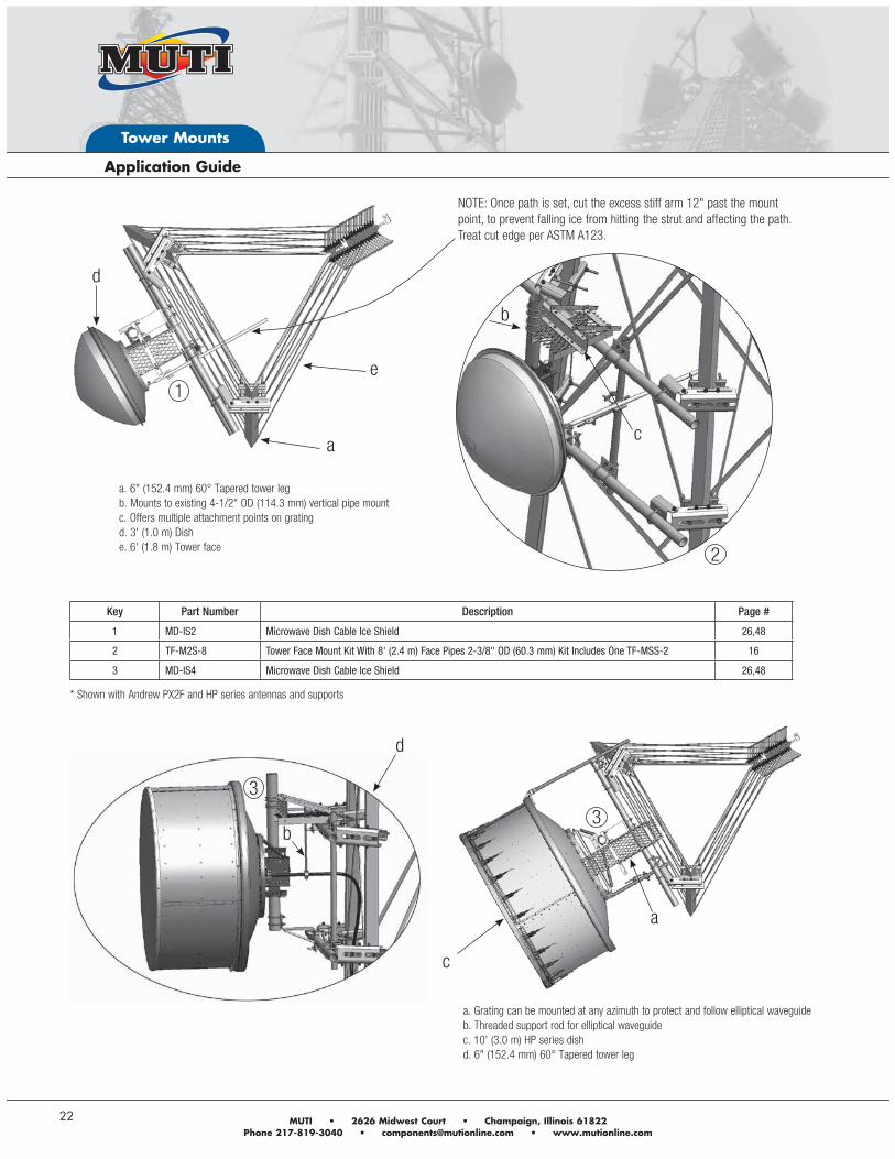
Key Part Number Description Page #
1 MD-IS2 Microwave Dish Cable Ice Shield 26,48
2 TF-M2S-8 Tower Face Mount Kit With 8' (2.4 m) Face Pipes 2-3/8" OD (60.3 mm) Kit Includes One TF-MSS-2 16
3 MD-IS4 Microwave Dish Cable Ice Shield 26,48
d
a
e
a. 6" (152.4 mm) 60° Tapered tower leg
b. Mounts to existing 4-1/2" OD (114.3 mm) vertical pipe mount
c. Offers multiple attachment points on grating
d. 3' (1.0 m) Dish
e. 6' (1.8 m) Tower face
a. Grating can be mounted at any azimuth to protect and follow elliptical waveguide
b. Threaded support rod for elliptical waveguide
c. 10' (3.0 m) HP series dish
d. 6" (152.4 mm) 60° Tapered tower leg
c
d
a
b
* Shown with Andrew PX2F and HP series antennas and supports
b
c
2
1
3
3
NOTE: Once path is set, cut the excess stiff arm 12" past the mount point, to prevent falling ice from hitting the strut and affecting the path. Treat cut edge per ASTM A123.
Andrew Solutions www.commscope.com/andrew
Tower Mounts
23
+5°+25°
-25°-5°
+5°+25°
-25°-5°
+25°
-25°-25°
+25°Out Board Strut Load
Adjustable Strut Load
+25°-25°
+25°-25°
Adjustable Strut Load
+25°-25°
Tower Mounts
24
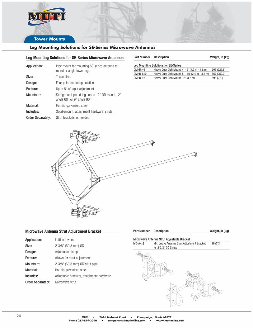
Part Number Description Weight, lb (kg) Leg Mounting Solutions for SE-SeriesDMHD-46 Heavy Duty Dish Mount, 4' - 6' (1.2 m - 1.8 m) 503 (227.8)DMHD-810 Heavy Duty Dish Mount, 8' - 10' (2.4 m - 3.1 m) 557 (252.3)DMHD-12 Heavy Duty Dish Mount, 12' (3.7 m) 598 (270)
Microwave Antenna Strut Adjustment Bracket
Application: Lattice towers
Size: 2-3/8" (60.3 mm) OD
Design: Adjustable clamps
Feature: Allows for strut adjustment
Mounts to: 2-3/8" (60.3 mm) OD strut pipe
Material: Hot dip galvanized steel
Includes: Adjustable brackets, attachment hardware
Order Separately: Microwave strut
Part Number Description Weight, lb (kg) Microwave Antenna Strut Adjustable BracketMD-AK-2 Microwave Antenna Strut Adjustment Bracket 16 (7.3) for 2-3/8" OD Struts
Leg Mounting Solutions for SE-Series Microwave Antennas
Application: Pipe mount for mounting SE-series antenna to round or angle tower legs
Size: Three sizes
Design: Four point mounting solution
Feature: Up to 8" of taper adjustment
Mounts to: Straight or tapered legs up to 12" OD round, 12" angle 60° or 9" angle 90°
Material: Hot dip galvanized steel
Includes: Saddlemount, attachment hardware, struts
Order Separately: Strut brackets as needed
Andrew Solutions www.commscope.com/andrew
Tower Mounts
25
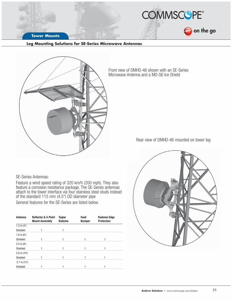
Front view of DMHD-46 shown with an SE-Series Microwave Antenna and a MD-S6 Ice Shield
Rear view of DMHD-46 mounted on tower leg
SE-Series Antennas:Feature a wind speed rating of 320 km/h (200 mph). They also feature a corrosion resistance package. The SE-Series antennas attach to the tower interface via four stainless steel studs instead of the standard 115 mm (4.5") OD diameter pipeGeneral features for the SE-Series are listed below.
Antenna Reflector & 4-Point Teglar Feed Radome Edge Mount Assembly Radome Bumper Protection
1.2 m (4')
Shielded 1 1
1.8 m (6')
Shielded 1 1 1 1
2.4 m (8')
Shielded 1 1 1 1
3.0 m (10')
Shielded 1 1 1 1
3.7 m (12')
Shielded 1 1 1 1
Tower Mounts
26
MD-IS2
MD-WS
MD-IS4
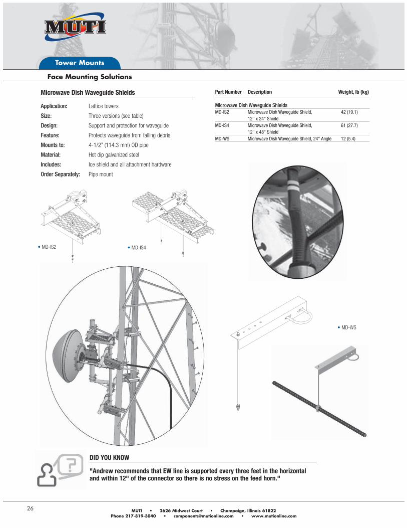
Microwave Dish Waveguide Shields
Application: Lattice towers
Size: Three versions (see table)
Design: Support and protection for waveguide
Feature: Protects waveguide from falling debris
Mounts to: 4-1/2” (114.3 mm) OD pipe
Material: Hot dip galvanized steel
Includes: Ice shield and all attachment hardware
Order Separately: Pipe mount
Part Number Description Weight, lb (kg) Microwave Dish Waveguide ShieldsMD-IS2 Microwave Dish Waveguide Shield, 42 (19.1) 12" x 24" ShieldMD-IS4 Microwave Dish Waveguide Shield, 61 (27.7) 12" x 48" ShieldMD-WS Microwave Dish Waveguide Shield, 24" Angle 12 (5.4)
DID YOU KNOW
"Andrew recommends that EW line is supported every three feet in the horizontal and within 12" of the connector so there is no stress on the feed horn."
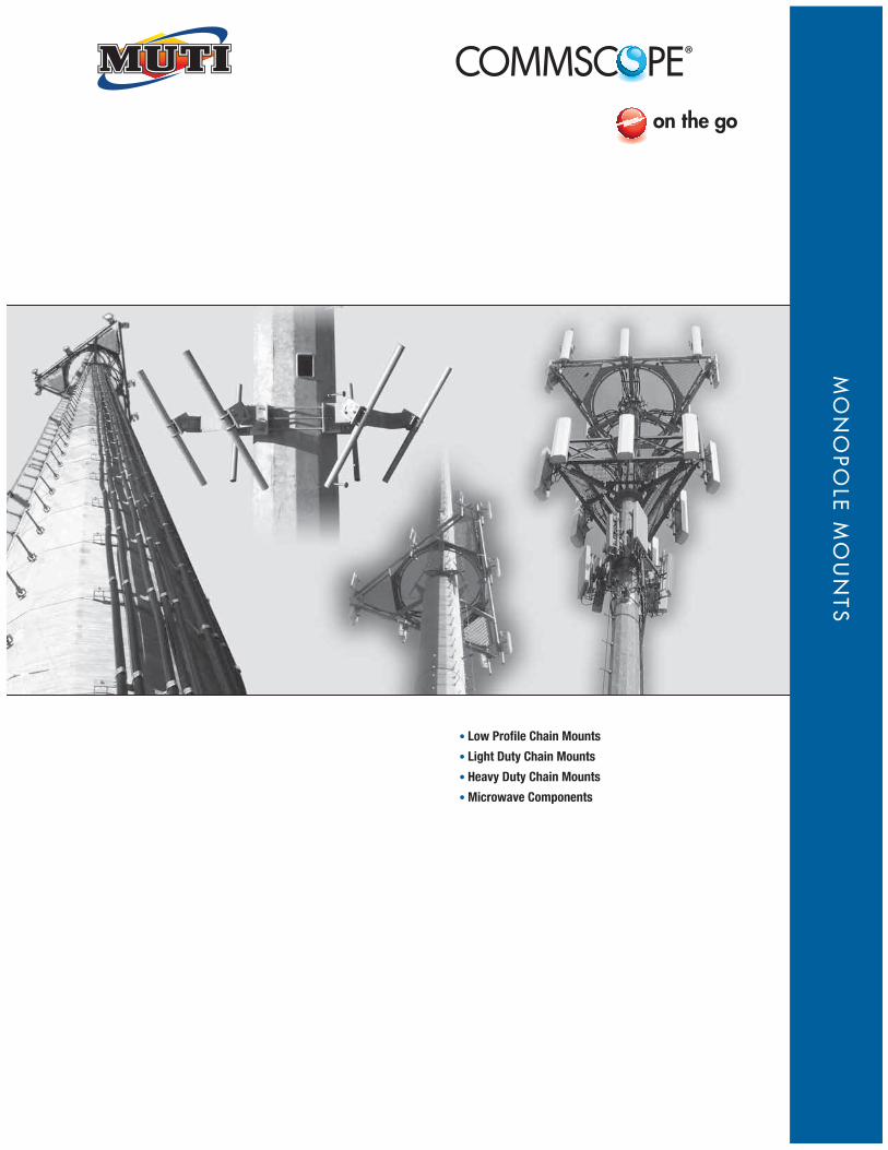
Low Profile Chain Mounts
Light Duty Chain Mounts
Heavy Duty Chain Mounts
Microwave Components
MO
NO
PO
LE M
OU
NTS
Monopole Mounts
28
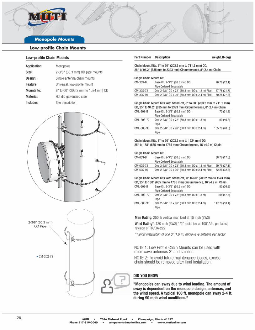
NOTE 2: To avoid future maintenance issues, excess chain should be removed after final installation.
DID YOU KNOW
"Monopoles can sway due to wind loading. The amount of sway is dependent on the monopole design, antennas, and the wind speed. A typical 100 ft. monopole can sway 2-4 ft. during 90 mph wind conditions."
NOTE 1: Low Profile Chain Mounts can be used with microwave antennas 3' and smaller.
Low-profile Chain Mounts
Application: Monopoles
Size: 2-3/8" (60.3 mm) OD pipe mounts
Design: Single antenna chain mounts
Feature: Universal, low-profile mount
Mounts to: 8" to 60" (203.2 mm to 1524 mm) OD
Material: Hot dip galvanized steel
Includes: See description
Part Number Description Weight, lb (kg) Chain Mount Kits, 8" to 30" (203.2 mm to 711.2 mm) OD, 25" to 94.2" (635 mm to 2393 mm) Circumference, 8' (2.4 m) Chain Single Chain Mount Kit CM-30S-B Base Kit, 2-3/8" (60.3 mm) OD, 26.76 (12.1) Pipe Ordered Separately CM-30S-72 One 2-3/8" OD x 72" (60.3 mm OD x 1.8 m) Pipe 47.76 (21.7)CM-30S-96 One 2-3/8" OD x 96" (60.3 mm OD x 2.4 m) Pipe 60.26 (27.3) Single Chain Mount Kits With Stand-off, 8" to 30" (203.2 mm to 711.2 mm) OD, 25" to 94.2" (635 mm to 2393 mm) Circumference, 8' (2.4 m) ChainCML-30S-B Base Kit, 2-3/8" (60.3 mm) OD, 70 (31.8) Pipe Ordered Separately CML-30S-72 One 2-3/8" OD x 72" (60.3 mm OD x 1.8 m) 90 (40.8) Pipe CML-30S-96 One 2-3/8" OD x 96" (60.3 mm OD x 2.4 m) 105.76 (48.0) Pipe Chain Mount Kits, 8" to 60" (203.2 mm to 1524 mm) OD, 25" to 188" (635 mm to 4785 mm) Circumference, 16' (4.9 m) Chain Single Chain Mount KitCM-60S-B Base Kit, 2-3/8" (60.3 mm) OD 38.78 (17.6) Pipe Ordered SeparatelyCM-60S-72 One 2-3/8" OD x 72" (60.3 mm OD x 1.8 m) Pipe 59.76 (27.1)CM-60S-96 One 2-3/8" OD x 96" (60.3 mm OD x 2.4 m) Pipe 72.26 (32.8) Single Chain Mount Kits With Stand-off, 8" to 60" (203.2 mm to 1524 mm) OD, 25" to 188" (635 mm to 4785 mm) Circumference, 16' (4.9 m) ChainCML-60S-B Base Kit, 2-3/8" (60.3 mm) OD, 80 (36.3) Pipe Ordered Separately CML-60S-72 One 2-3/8" OD x 72" (60.3 mm OD x 1.8 m) 105 (47.6) PipeCML-60S-96 One 2-3/8" OD x 96" (60.3 mm OD x 2.4 m) 117.76 (53.4) Pipe
Man Rating: 250 lb vertical man load at 15 mph (BWS)
Wind Rating*: 120 mph (BWS) 1/2" radial ice at 100' AGL per latest revision of TIA/EIA-222
*Typical installation of one 3' (1.0 m) microwave antenna per sector
2-3/8” (60.3 mm) OD Pipe
CM-30S-72
Monopole Mounts
Andrew Solutions www.commscope.com/andrew 29
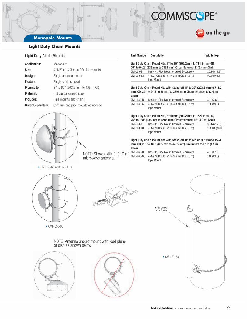
CM-L30-63 with CM-SL30
CML-L30-63
NOTE: Shown with 3' (1.0 m) microwave antenna.
NOTE: Antenna should mount with load plane of dish as shown below
Light Duty Chain Mounts
Application: Monopoles
Size: 4-1/2" (114.3 mm) OD pipe mounts
Design: Single antenna mount
Feature: Single chain support
Mounts to: 8" to 60" (203.2 mm to 1.5 m) OD
Material: Hot dip galvanized steel
Includes: Pipe mounts and chains
Order Separately: Stiff arm and pipe mounts as needed
Part Number Description Wt. lb (kg) Light Duty Chain Mount Kits, 8" to 30" (203.2 mm to 711.2 mm) OD, 25" to 94.2" (635 mm to 2393 mm) Circumference, 8' (2.4 m) ChainCM-L30-B Base Kit, Pipe Mount Ordered Separately 26.14 (11.9)CM-L30-63 4-1/2" OD x 63" (114.3 mm OD x 1.6 m) 90.64 (41.1) Pipe Mount Light Duty Chain Mount Kits With Stand-off, 8" to 30" (203.2 mm to 711.2 mm) OD, 25" to 94.2" (635 mm to 2393 mm) Circumference, 8' (2.4 m) ChainCML-L30-B Base Kit, Pipe Mount Ordered Separately 30 (13.6)CML-L30-63 4-1/2" OD x 63" (114.3 mm OD x 1.6 m) 130 (59.0) Pipe Mount Light Duty Chain Mount Kits, 8" to 60" (203.2 mm to 1524 mm) OD, 25" to 188" (635 mm to 4785 mm) Circumference, 16' (4.9 m) ChainCM-L60-B Base Kit, Pipe Mount Ordered Separately 38.14 (17.3)CM-L60-63 4-1/2" OD x 63" (114.3 mm OD x 1.6 m) 102.64 (46.6) Pipe Mount Light Duty Chain Mount Kits With Stand-off, 8" to 60" (203.2 mm to 1524 mm) OD, 25" to 188" (635 mm to 4785 mm) Circumference, 16' (4.9 m) ChainCML-L60-B Base Kit, Pipe Mount Ordered Separately 40 (18.1)CML-L60-63 4-1/2" OD x 63" (114.3 mm OD x 1.6 m) 140 (63.5) Pipe Mount
4-1/2” OD Pipe(114.3 mm)
CM-L30-63
Monopole Mounts
30
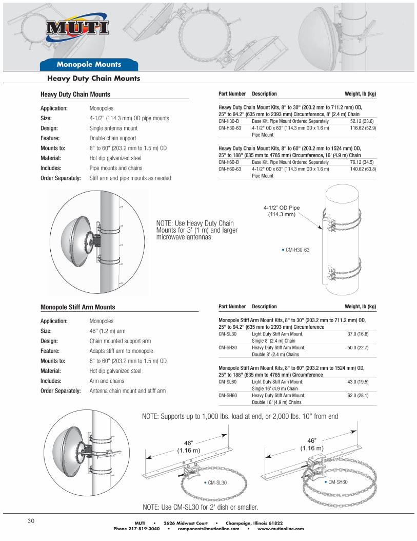
NOTE: Supports up to 1,000 lbs. load at end, or 2,000 lbs. 10" from end
NOTE: Use Heavy Duty Chain Mounts for 3' (1 m) and larger microwave antennas
NOTE: Use CM-SL30 for 2' dish or smaller.
4-1/2” OD Pipe (114.3 mm)
Heavy Duty Chain Mounts
Application: Monopoles
Size: 4-1/2" (114.3 mm) OD pipe mounts
Design: Single antenna mount
Feature: Double chain support
Mounts to: 8" to 60" (203.2 mm to 1.5 m) OD
Material: Hot dip galvanized steel
Includes: Pipe mounts and chains
Order Separately: Stiff arm and pipe mounts as needed
Part Number Description Weight, lb (kg) Heavy Duty Chain Mount Kits, 8" to 30" (203.2 mm to 711.2 mm) OD, 25" to 94.2" (635 mm to 2393 mm) Circumference, 8' (2.4 m) ChainCM-H30-B Base Kit, Pipe Mount Ordered Separately 52.12 (23.6)CM-H30-63 4-1/2" OD x 63" (114.3 mm OD x 1.6 m) 116.62 (52.9) Pipe Mount Heavy Duty Chain Mount Kits, 8" to 60" (203.2 mm to 1524 mm) OD, 25" to 188" (635 mm to 4785 mm) Circumference, 16' (4.9 m) ChainCM-H60-B Base Kit, Pipe Mount Ordered Separately 76.12 (34.5)CM-H60-63 4-1/2" OD x 63" (114.3 mm OD x 1.6 m) 140.62 (63.8) Pipe Mount
Monopole Stiff Arm Mounts
Application: Monopoles
Size: 48" (1.2 m) arm
Design: Chain mounted support arm
Feature: Adapts stiff arm to monopole
Mounts to: 8" to 60" (203.2 mm to 1.5 m) OD
Material: Hot dip galvanized steel
Includes: Arm and chains
Order Separately: Antenna chain mount and stiff arm
Part Number Description Weight, lb (kg) Monopole Stiff Arm Mount Kits, 8" to 30" (203.2 mm to 711.2 mm) OD, 25" to 94.2" (635 mm to 2393 mm) CircumferenceCM-SL30 Light Duty Stiff Arm Mount, 37.0 (16.8) Single 8' (2.4 m) Chain CM-SH30 Heavy Duty Stiff Arm Mount, 50.0 (22.7) Double 8' (2.4 m) Chains Monopole Stiff Arm Mount Kits, 8" to 60" (203.2 mm to 1524 mm) OD, 25" to 188" (635 mm to 4785 mm) CircumferenceCM-SL60 Light Duty Stiff Arm Mount, 43.0 (19.5) Single 16' (4.9 m) Chain CM-SH60 Heavy Duty Stiff Arm Mount, 62.0 (28.1) Double 16' (4.9 m) Chains
46”(1.16 m)
46”(1.16 m)
CM-H30-63
CM-SL30 CM-SH60
Monopole Mounts
Andrew Solutions www.commscope.com/andrew 31
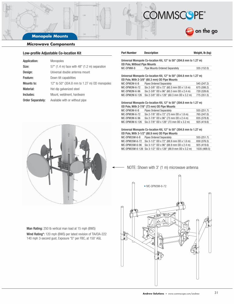
NOTE: Shown with 3' (1 m) microwave antenna
Low-profile Adjustable Co-location Kit
Application: Monopoles
Size: 57" (1.4 m) face with 48" (1.2 m) separation
Design: Universal double antenna mount
Feature: Down tilt capabilities
Mounts to: 12" to 50" (304.8 mm to 1.27 m) OD monopoles
Material: Hot dip galvanized steel
Includes: Mount, weldment, hardware
Order Separately: Available with or without pipe
Part Number Description Weight, lb (kg) Universal Monopole Co-location Kit, 12" to 50" (304.8 mm to 1.27 m) OD Pole, Without Pipe MountsMC-DPMM-B Pipe Mounts Ordered Separately 335 (152.0) Universal Monopole Co-location Kit, 12" to 50" (304.8 mm to 1.27 m) OD Pole, With 2-3/8" (60.3 mm) OD Pipe MountsMC-DPM2M-6-B Pipes Ordered Separately 545 (247.2)MC-DPM2M-6-72 Six 2-3/8" OD x 72" (60.3 mm OD x 1.8 m) 675 (306.2)MC-DPM2M-6-96 Six 2-3/8" OD x 96" (60.3 mm OD x 2.4 m) 720 (326.6)MC-DPM2M-6-126 Six 2-3/8" OD x 126" (60.3 mm OD x 3.2 m) 775 (351.5) Universal Monopole Co-location Kit, 12" to 50" (304.8 mm to 1.27 m) OD Pole, With 2-7/8" (73 mm) OD Pipe MountsMC-DPM3M-6-B Pipes Ordered Separately 555 (251.7)MC-DPM3M-6-72 Six 2-7/8" OD x 72" (73 mm OD x 1.8 m) 765 (347.0)MC-DPM3M-6-96 Six 2-7/8" OD x 96" (73 mm OD x 2.4 m) 835 (378.8)MC-DPM3M-6-126 Six 2-7/8" OD x 126" (73 mm OD x 3.2 m) 925 (419.6) Universal Monopole Co-location Kit, 12" to 50" (304.8 mm to 1.27 m) OD Pole, With 3-1/2" (88.9 mm) OD Pipe MountsMC-DPM35M-6-B Pipes Ordered Separately 555 (251.7)MC-DPM35M-6-72 Six 3-1/2" OD x 72" (88.9 mm OD x 1.8 m) 830 (376.5)MC-DPM35M-6-96 Six 3-1/2" OD x 96" (88.9 mm OD x 2.4 m) 925 (419.6)MC-DPM35M-6-126 Six 3-1/2" OD x 126" (88.9 mm OD x 3.2 m) 1035 (469.5)
Man Rating: 250 lb vertical man load at 15 mph (BWS)
Wind Rating*: 120 mph (BWS) per latest revision of TIA/EIA-222 140 mph 3-second gust, Exposure “D” per FBC, at 150' AGL
MC-DPM3M-6-72
Monopole Mounts
32
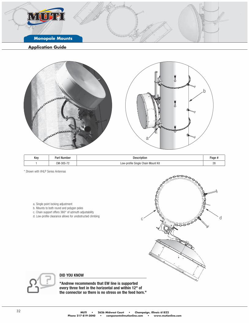
a. Single point locking adjustment
b. Mounts to both round and polygon poles
c. Chain support offers 360° of azimuth adjustability
d. Low-profile clearance allows for unobstructed climbing
Key Part Number Description Page #
1 CM-30S-72 Low-profile Single Chain Mount Kit 28
* Shown with VHLP Series Antennas
DID YOU KNOW
"Andrew recommends that EW line is supported every three feet in the horizontal and within 12" of the connector so there is no stress on the feed horn."
Monopole Mounts
Andrew Solutions www.commscope.com/andrew 33
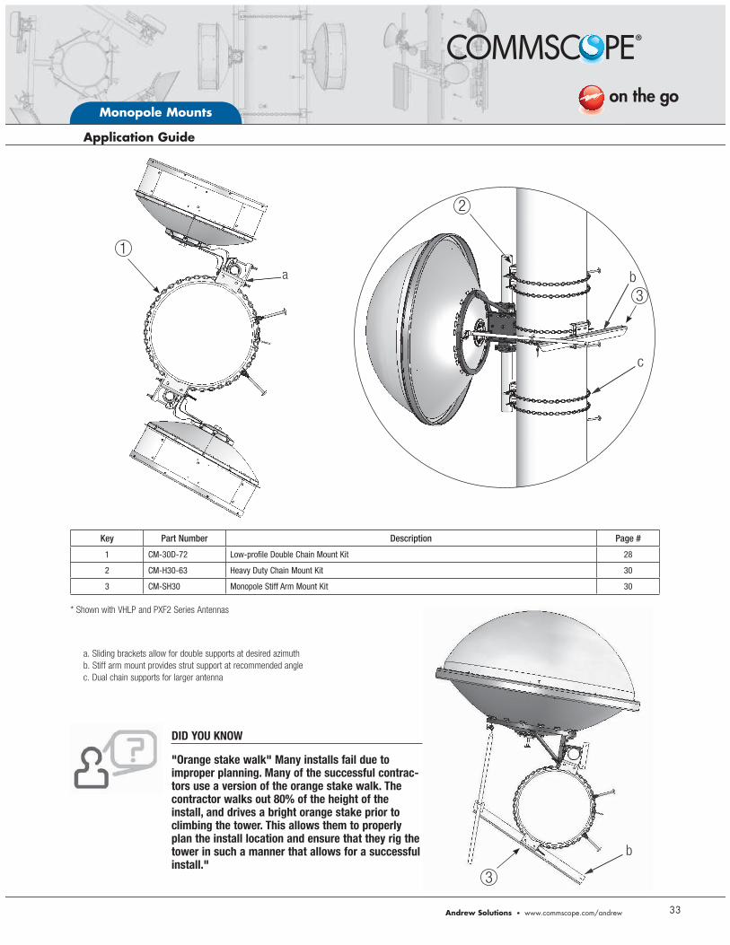
a. Sliding brackets allow for double supports at desired azimuth
b. Stiff arm mount provides strut support at recommended angle
c. Dual chain supports for larger antenna
Key Part Number Description Page #
1 CM-30D-72 Low-profile Double Chain Mount Kit 28
2 CM-H30-63 Heavy Duty Chain Mount Kit 30
3 CM-SH30 Monopole Stiff Arm Mount Kit 30
* Shown with VHLP and PXF2 Series Antennas
DID YOU KNOW
"Orange stake walk" Many installs fail due to improper planning. Many of the successful contrac-tors use a version of the orange stake walk. The contractor walks out 80% of the height of the install, and drives a bright orange stake prior to climbing the tower. This allows them to properly plan the install location and ensure that they rig the tower in such a manner that allows for a successful install."
1
2
3
3
Monopole Mounts
34
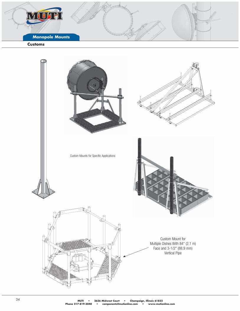
Custom Mount for Multiple Dishes With 84" (2.1 m)
Face and 3-1/2" (88.9 mm) Vertical Pipe
Custom Mounts for Specific Applications
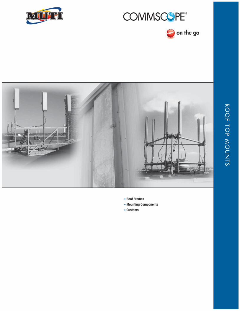
Roof Frames
Mounting Components
Customs
RO
OF-TO
P M
OU
NTS
Roof-Top Mounts
36
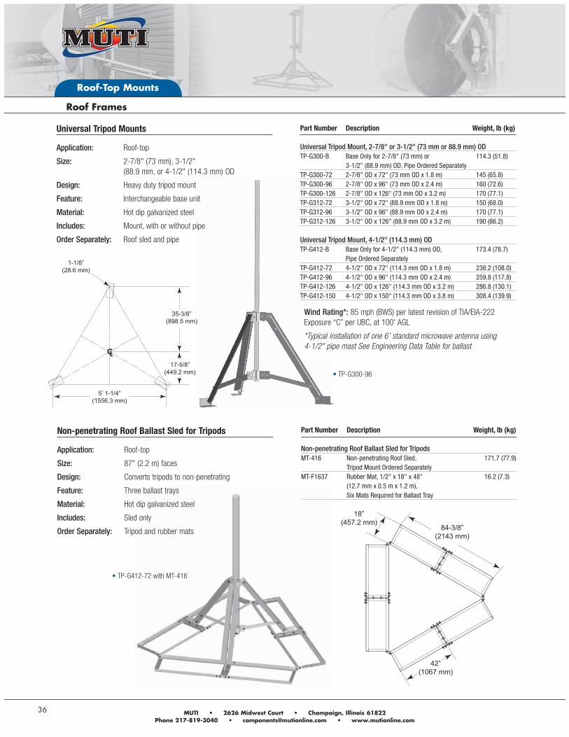
Part Number Description Weight, lb (kg) Universal Tripod Mount, 2-7/8" or 3-1/2" (73 mm or 88.9 mm) ODTP-G300-B Base Only for 2-7/8" (73 mm) or 114.3 (51.8) 3-1/2" (88.9 mm) OD, Pipe Ordered SeparatelyTP-G300-72 2-7/8" OD x 72" (73 mm OD x 1.8 m) 145 (65.8)TP-G300-96 2-7/8" OD x 96" (73 mm OD x 2.4 m) 160 (72.6)TP-G300-126 2-7/8" OD x 126" (73 mm OD x 3.2 m) 170 (77.1)TP-G312-72 3-1/2" OD x 72" (88.9 mm OD x 1.8 m) 150 (68.0)TP-G312-96 3-1/2" OD x 96" (88.9 mm OD x 2.4 m) 170 (77.1)TP-G312-126 3-1/2" OD x 126" (88.9 mm OD x 3.2 m) 190 (86.2) Universal Tripod Mount, 4-1/2" (114.3 mm) ODTP-G412-B Base Only for 4-1/2" (114.3 mm) OD, 173.4 (78.7) Pipe Ordered Separately TP-G412-72 4-1/2" OD x 72" (114.3 mm OD x 1.8 m) 238.2 (108.0)TP-G412-96 4-1/2" OD x 96" (114.3 mm OD x 2.4 m) 259.8 (117.8)TP-G412-126 4-1/2" OD x 126" (114.3 mm OD x 3.2 m) 286.8 (130.1)TP-G412-150 4-1/2" OD x 150" (114.3 mm OD x 3.8 m) 308.4 (139.9)
1-1/8”(28.6 mm)
35-3/8”(898.5 mm)
17-5/8”(449.2 mm)
5’ 1-1/4”(1556.3 mm)
Non-penetrating Roof Ballast Sled for Tripods
Application: Roof-top
Size: 87" (2.2 m) faces
Design: Converts tripods to non-penetrating
Feature: Three ballast trays
Material: Hot dip galvanized steel
Includes: Sled only
Order Separately: Tripod and rubber mats
Part Number Description Weight, lb (kg) Non-penetrating Roof Ballast Sled for TripodsMT-416 Non-penetrating Roof Sled, 171.7 (77.9) Tripod Mount Ordered Separately MT-F1637 Rubber Mat, 1/2" x 18" x 48" 16.2 (7.3) (12.7 mm x 0.5 m x 1.2 m), Six Mats Required for Ballast Tray
18”(457.2 mm)
84-3/8”(2143 mm)
42”(1067 mm)
Wind Rating*: 85 mph (BWS) per latest revision of TIA/EIA-222 Exposure “C” per UBC, at 100' AGL
*Typical installation of one 6' standard microwave antenna using 4-1/2" pipe mast See Engineering Data Table for ballast
TP-G412-72 with MT-416
Universal Tripod Mounts
Application: Roof-top
Size: 2-7/8" (73 mm), 3-1/2" (88.9 mm, or 4-1/2" (114.3 mm) OD
Design: Heavy duty tripod mount
Feature: Interchangeable base unit
Material: Hot dip galvanized steel
Includes: Mount, with or without pipe
Order Separately: Roof sled and pipe
TP-G300-96
Andrew Solutions www.commscope.com/andrew
Roof-Top Mounts
37
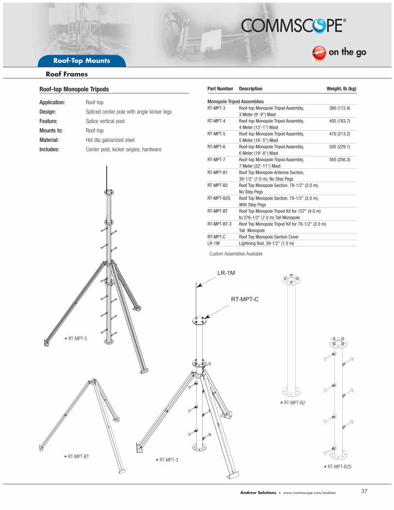
RT-MPT-BTRT-MPT-3
RT-MPT-B2S
RT-MPT-B2
RT-MPT-5
LR-1M
RT-MPT-C
Roof-top Monopole Tripods
Application: Roof-top
Design: Spliced center pole with angle kicker legs
Feature: Splice vertical post
Mounts to: Roof-top
Material: Hot dip galvanized steel
Includes: Center post, kicker angles, hardware
Part Number Description Weight, lb (kg) Monopole Tripod AssembliesRT-MPT-3 Roof-top Monopole Tripod Assembly, 380 (172.4) 3 Meter (9'-9") MastRT-MPT-4 Roof-top Monopole Tripod Assembly, 405 (183.7) 4 Meter (13'-1") MastRT-MPT-5 Roof-top Monopole Tripod Assembly, 470 (213.2) 5 Meter (16'-5") MastRT-MPT-6 Roof-top Monopole Tripod Assembly, 505 (229.1) 6 Meter (19'-8") MastRT-MPT-7 Roof-top Monopole Tripod Assembly, 565 (256.3) 7 Meter (22'-11") MastRT-MPT-B1 Roof Top Monopole Antenna Section, 39-1/2" (1.0 m), No Step PegsRT-MPT-B2 Roof Top Monopole Section, 78-1/2" (2.0 m), No Step PegsRT-MPT-B2S Roof Top Monopole Section, 78-1/2" (2.0 m), With Step PegsRT-MPT-BT Roof Top Monopole Tripod Kit for 157" (4.0 m) to 276-1/2" (7.0 m) Tall MonopoleRT-MPT-BT-3 Roof Top Monopole Tripod Kit for 78-1/2" (2.0 m) Tall MonopoleRT-MPT-C Roof Top Monopole Section CoverLR-1M Lightning Rod, 39-1/2" (1.0 m)
Custom Assemblies Available
Roof-Top Mounts
38
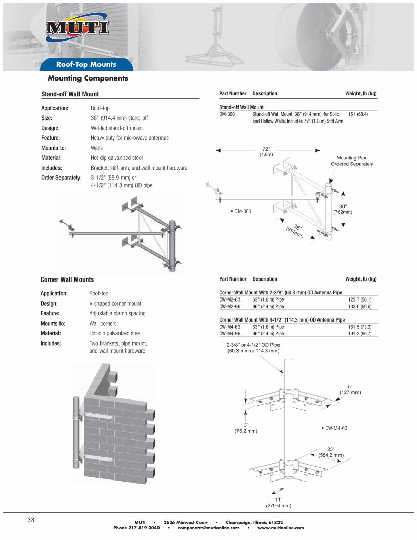
Mounting PipeOrdered Separately
Stand-off Wall Mount
Application: Roof-top
Size: 36" (914.4 mm) stand-off
Design: Welded stand-off mount
Feature: Heavy duty for microwave antennas
Mounts to: Walls
Material: Hot dip galvanized steel
Includes: Bracket, stiff-arm, and wall mount hardware
Order Separately: 3-1/2" (88.9 mm) or 4-1/2" (114.3 mm) OD pipe
Part Number Description Weight, lb (kg) Stand-off Wall MountDM-300 Stand-off Wall Mount, 36" (914 mm), for Solid 151 (68.4) and Hollow Walls, Includes 72" (1.8 m) Stiff Arm
Corner Wall Mounts
Application: Roof-top
Design: V-shaped corner mount
Feature: Adjustable clamp spacing
Mounts to: Wall corners
Material: Hot dip galvanized steel
Includes: Two brackets, pipe mount, and wall mount hardware
Part Number Description Weight, lb (kg) Corner Wall Mount With 2-3/8" (60.3 mm) OD Antenna PipeCW-M2-63 63" (1.6 m) Pipe 123.7 (56.1)CW-M2-96 96" (2.4 m) Pipe 133.6 (60.6) Corner Wall Mount With 4-1/2" (114.3 mm) OD Antenna PipeCW-M4-63 63" (1.6 m) Pipe 161.5 (73.3)CW-M4-96 96" (2.4 m) Pipe 191.2 (86.7)
2-3/8” or 4-1/2” OD Pipe(60.3 mm or 114.3 mm)
5”(127 mm)
3”(76.2 mm)
11”(279.4 mm)
23”(584.2 mm)
DM-300
CW-M4-63
Andrew Solutions www.commscope.com/andrew
Roof-Top Mounts
39
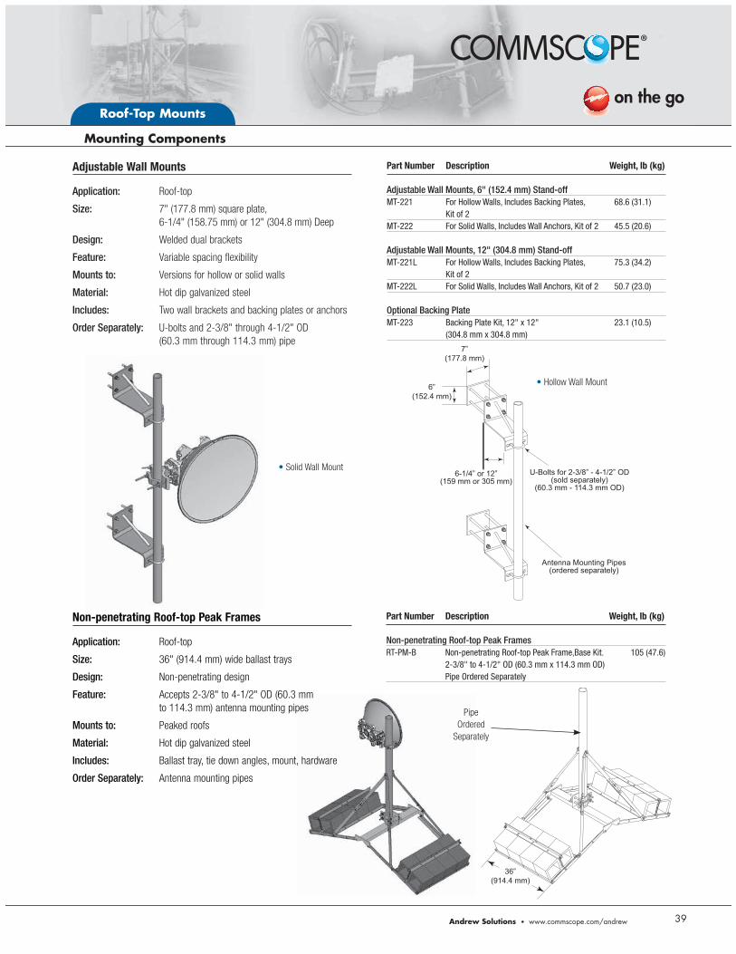
Hollow Wall Mount
Solid Wall Mount
Adjustable Wall Mounts
Application: Roof-top
Size: 7" (177.8 mm) square plate, 6-1/4" (158.75 mm) or 12" (304.8 mm) Deep
Design: Welded dual brackets
Feature: Variable spacing flexibility
Mounts to: Versions for hollow or solid walls
Material: Hot dip galvanized steel
Includes: Two wall brackets and backing plates or anchors
Order Separately: U-bolts and 2-3/8" through 4-1/2" OD (60.3 mm through 114.3 mm) pipe
Part Number Description Weight, lb (kg) Adjustable Wall Mounts, 6" (152.4 mm) Stand-offMT-221 For Hollow Walls, Includes Backing Plates, 68.6 (31.1) Kit of 2MT-222 For Solid Walls, Includes Wall Anchors, Kit of 2 45.5 (20.6) Adjustable Wall Mounts, 12" (304.8 mm) Stand-offMT-221L For Hollow Walls, Includes Backing Plates, 75.3 (34.2) Kit of 2MT-222L For Solid Walls, Includes Wall Anchors, Kit of 2 50.7 (23.0) Optional Backing PlateMT-223 Backing Plate Kit, 12" x 12" 23.1 (10.5) (304.8 mm x 304.8 mm)
U-Bolts for 2-3/8” - 4-1/2” OD(sold separately)
(60.3 mm - 114.3 mm OD)
Antenna Mounting Pipes(ordered separately)
6-1/4” or 12”(159 mm or 305 mm)
7”(177.8 mm)
6”(152.4 mm)
Non-penetrating Roof-top Peak Frames
Application: Roof-top
Size: 36" (914.4 mm) wide ballast trays
Design: Non-penetrating design
Feature: Accepts 2-3/8" to 4-1/2" OD (60.3 mm to 114.3 mm) antenna mounting pipes
Mounts to: Peaked roofs
Material: Hot dip galvanized steel
Includes: Ballast tray, tie down angles, mount, hardware
Order Separately: Antenna mounting pipes
Part Number Description Weight, lb (kg) Non-penetrating Roof-top Peak FramesRT-PM-B Non-penetrating Roof-top Peak Frame,Base Kit. 105 (47.6) 2-3/8" to 4-1/2" OD (60.3 mm x 114.3 mm OD) Pipe Ordered Separately
36”(914.4 mm)
Pipe
Ordered
Separately
Roof-Top Mounts
40
7-1/2" or 14”(190 mm or 355.6 mm)
SLOT 4-1/2" Long(114.3 mm)
2-3/8" or 4-1/2" OD(60.3 mm or 114.3 mm)
NOTE: Not recommended for use on the climbing leg of tower. Use PM-SC series (see page 2).
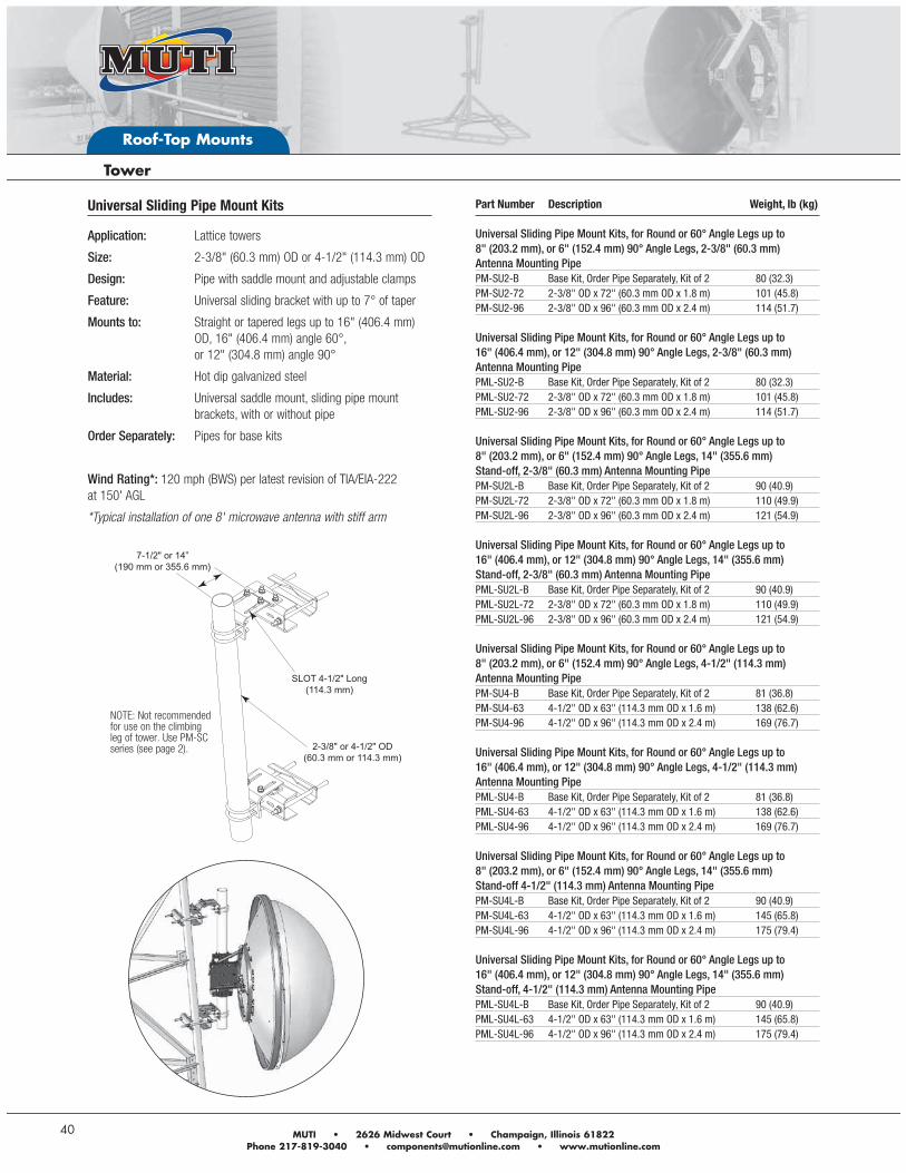
Universal Sliding Pipe Mount Kits
Application: Lattice towers
Size: 2-3/8" (60.3 mm) OD or 4-1/2" (114.3 mm) OD
Design: Pipe with saddle mount and adjustable clamps
Feature: Universal sliding bracket with up to 7° of taper
Mounts to: Straight or tapered legs up to 16" (406.4 mm) OD, 16" (406.4 mm) angle 60°, or 12" (304.8 mm) angle 90°
Material: Hot dip galvanized steel
Includes: Universal saddle mount, sliding pipe mount brackets, with or without pipe
Order Separately: Pipes for base kits
Wind Rating*: 120 mph (BWS) per latest revision of TIA/EIA-222 at 150' AGL
*Typical installation of one 8' microwave antenna with stiff arm
Part Number Description Weight, lb (kg) Universal Sliding Pipe Mount Kits, for Round or 60° Angle Legs up to 8" (203.2 mm), or 6" (152.4 mm) 90° Angle Legs, 2-3/8" (60.3 mm) Antenna Mounting PipePM-SU2-B Base Kit, Order Pipe Separately, Kit of 2 80 (32.3)PM-SU2-72 2-3/8" OD x 72" (60.3 mm OD x 1.8 m) 101 (45.8)PM-SU2-96 2-3/8" OD x 96" (60.3 mm OD x 2.4 m) 114 (51.7) Universal Sliding Pipe Mount Kits, for Round or 60° Angle Legs up to 16" (406.4 mm), or 12" (304.8 mm) 90° Angle Legs, 2-3/8" (60.3 mm) Antenna Mounting PipePML-SU2-B Base Kit, Order Pipe Separately, Kit of 2 80 (32.3)PML-SU2-72 2-3/8" OD x 72" (60.3 mm OD x 1.8 m) 101 (45.8)PML-SU2-96 2-3/8" OD x 96" (60.3 mm OD x 2.4 m) 114 (51.7) Universal Sliding Pipe Mount Kits, for Round or 60° Angle Legs up to 8" (203.2 mm), or 6" (152.4 mm) 90° Angle Legs, 14" (355.6 mm) Stand-off, 2-3/8" (60.3 mm) Antenna Mounting PipePM-SU2L-B Base Kit, Order Pipe Separately, Kit of 2 90 (40.9)PM-SU2L-72 2-3/8" OD x 72" (60.3 mm OD x 1.8 m) 110 (49.9)PM-SU2L-96 2-3/8" OD x 96" (60.3 mm OD x 2.4 m) 121 (54.9) Universal Sliding Pipe Mount Kits, for Round or 60° Angle Legs up to 16" (406.4 mm), or 12" (304.8 mm) 90° Angle Legs, 14" (355.6 mm) Stand-off, 2-3/8" (60.3 mm) Antenna Mounting PipePML-SU2L-B Base Kit, Order Pipe Separately, Kit of 2 90 (40.9)PML-SU2L-72 2-3/8" OD x 72" (60.3 mm OD x 1.8 m) 110 (49.9)PML-SU2L-96 2-3/8" OD x 96" (60.3 mm OD x 2.4 m) 121 (54.9) Universal Sliding Pipe Mount Kits, for Round or 60° Angle Legs up to 8" (203.2 mm), or 6" (152.4 mm) 90° Angle Legs, 4-1/2" (114.3 mm) Antenna Mounting PipePM-SU4-B Base Kit, Order Pipe Separately, Kit of 2 81 (36.8)PM-SU4-63 4-1/2" OD x 63" (114.3 mm OD x 1.6 m) 138 (62.6)PM-SU4-96 4-1/2" OD x 96" (114.3 mm OD x 2.4 m) 169 (76.7) Universal Sliding Pipe Mount Kits, for Round or 60° Angle Legs up to 16" (406.4 mm), or 12" (304.8 mm) 90° Angle Legs, 4-1/2" (114.3 mm) Antenna Mounting PipePML-SU4-B Base Kit, Order Pipe Separately, Kit of 2 81 (36.8)PML-SU4-63 4-1/2" OD x 63" (114.3 mm OD x 1.6 m) 138 (62.6)PML-SU4-96 4-1/2" OD x 96" (114.3 mm OD x 2.4 m) 169 (76.7) Universal Sliding Pipe Mount Kits, for Round or 60° Angle Legs up to 8" (203.2 mm), or 6" (152.4 mm) 90° Angle Legs, 14" (355.6 mm) Stand-off 4-1/2" (114.3 mm) Antenna Mounting PipePM-SU4L-B Base Kit, Order Pipe Separately, Kit of 2 90 (40.9)PM-SU4L-63 4-1/2" OD x 63" (114.3 mm OD x 1.6 m) 145 (65.8)PM-SU4L-96 4-1/2" OD x 96" (114.3 mm OD x 2.4 m) 175 (79.4) Universal Sliding Pipe Mount Kits, for Round or 60° Angle Legs up to 16" (406.4 mm), or 12" (304.8 mm) 90° Angle Legs, 14" (355.6 mm) Stand-off, 4-1/2" (114.3 mm) Antenna Mounting PipePML-SU4L-B Base Kit, Order Pipe Separately, Kit of 2 90 (40.9)PML-SU4L-63 4-1/2" OD x 63" (114.3 mm OD x 1.6 m) 145 (65.8)PML-SU4L-96 4-1/2" OD x 96" (114.3 mm OD x 2.4 m) 175 (79.4)
Coaxial Support Components
Waveguide Bridge Kits
Cable Ladder Kits
WA
VE
GU
IDE
Waveguide
42
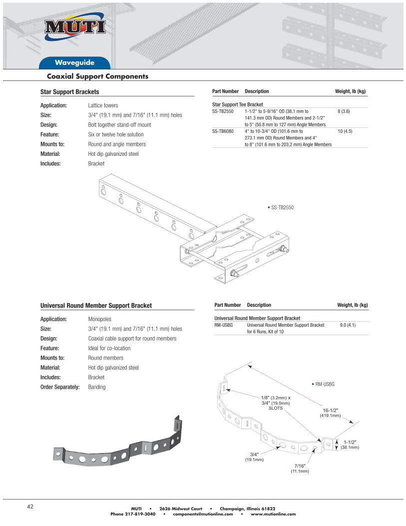
Star Support Brackets
Application: Lattice towers
Size: 3/4" (19.1 mm) and 7/16" (11.1 mm) holes
Design: Bolt together stand-off mount
Feature: Six or twelve hole solution
Mounts to: Round and angle members
Material: Hot dip galvanized steel
Includes: Bracket
Part Number Description Weight, lb (kg) Star Support Tee BracketSS-TB2550 1-1/2" to 5-9/16" OD (38.1 mm to 8 (3.6) 141.3 mm OD) Round Members and 2-1/2" to 5" (50.8 mm to 127 mm) Angle Members SS-TB6080 4" to 10-3/4" OD (101.6 mm to 10 (4.5) 273.1 mm OD) Round Members and 4" to 8" (101.6 mm to 203.2 mm) Angle Members
Universal Round Member Support Bracket
Application: Monopoles
Size: 3/4" (19.1 mm) and 7/16" (11.1 mm) holes
Design: Coaxial cable support for round members
Feature: Ideal for co-location
Mounts to: Round members
Material: Hot dip galvanized steel
Includes: Bracket
Order Separately: Banding
Part Number Description Weight, lb (kg) Universal Round Member Support BracketRM-USBG Universal Round Member Support Bracket 9.0 (4.1) for 6 Runs, Kit of 10
SS-TB2550
RM-USBG
Waveguide
Andrew Solutions www.commscope.com/andrew 43
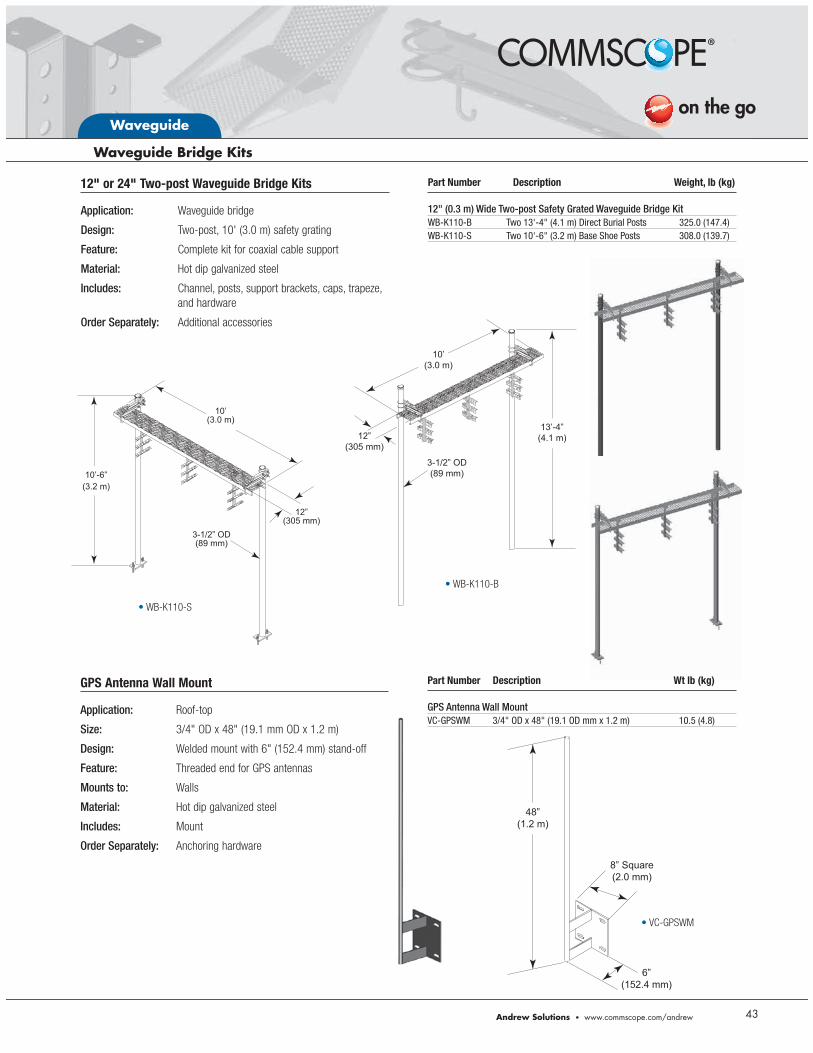
12" or 24" Two-post Waveguide Bridge Kits
Application: Waveguide bridge
Design: Two-post, 10' (3.0 m) safety grating
Feature: Complete kit for coaxial cable support
Material: Hot dip galvanized steel
Includes: Channel, posts, support brackets, caps, trapeze, and hardware
Order Separately: Additional accessories
Part Number Description Weight, lb (kg) 12" (0.3 m) Wide Two-post Safety Grated Waveguide Bridge KitWB-K110-B Two 13'-4" (4.1 m) Direct Burial Posts 325.0 (147.4)WB-K110-S Two 10'-6" (3.2 m) Base Shoe Posts 308.0 (139.7)
10’(3.0 m)
12”(305 mm)
3-1/2” OD(89 mm)
13’-4”(4.1 m)
WB-K110-B
10’-6”(3.2 m)
12”(305 mm)
10’(3.0 m)
3-1/2” OD(89 mm)
WB-K110-S
GPS Antenna Wall Mount
Application: Roof-top
Size: 3/4" OD x 48" (19.1 mm OD x 1.2 m)
Design: Welded mount with 6" (152.4 mm) stand-off
Feature: Threaded end for GPS antennas
Mounts to: Walls
Material: Hot dip galvanized steel
Includes: Mount
Order Separately: Anchoring hardware
Part Number Description Wt lb (kg) GPS Antenna Wall MountVC-GPSWM 3/4" OD x 48" (19.1 OD mm x 1.2 m) 10.5 (4.8)
8” Square(2.0 mm)
6”(152.4 mm)
48”(1.2 m)
VC-GPSWM
Waveguide
44
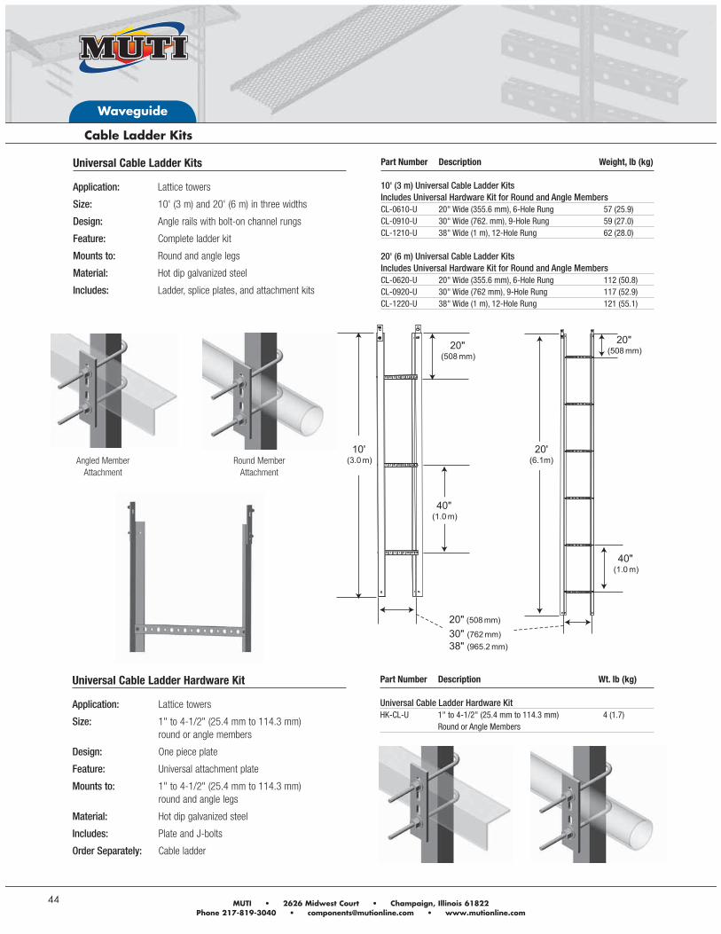
Universal Cable Ladder Kits
Application: Lattice towers
Size: 10' (3 m) and 20' (6 m) in three widths
Design: Angle rails with bolt-on channel rungs
Feature: Complete ladder kit
Mounts to: Round and angle legs
Material: Hot dip galvanized steel
Includes: Ladder, splice plates, and attachment kits
Part Number Description Weight, lb (kg) 10' (3 m) Universal Cable Ladder Kits Includes Universal Hardware Kit for Round and Angle MembersCL-0610-U 20" Wide (355.6 mm), 6-Hole Rung 57 (25.9)CL-0910-U 30" Wide (762. mm), 9-Hole Rung 59 (27.0)CL-1210-U 38" Wide (1 m), 12-Hole Rung 62 (28.0) 20' (6 m) Universal Cable Ladder Kits Includes Universal Hardware Kit for Round and Angle MembersCL-0620-U 20" Wide (355.6 mm), 6-Hole Rung 112 (50.8)CL-0920-U 30" Wide (762 mm), 9-Hole Rung 117 (52.9)CL-1220-U 38" Wide (1 m), 12-Hole Rung 121 (55.1)
Angled MemberAttachment
Round MemberAttachment
Universal Cable Ladder Hardware Kit
Application: Lattice towers
Size: 1" to 4-1/2" (25.4 mm to 114.3 mm) round or angle members
Design: One piece plate
Feature: Universal attachment plate
Mounts to: 1" to 4-1/2" (25.4 mm to 114.3 mm) round and angle legs
Material: Hot dip galvanized steel
Includes: Plate and J-bolts
Order Separately: Cable ladder
Part Number Description Wt. lb (kg) Universal Cable Ladder Hardware KitHK-CL-U 1" to 4-1/2" (25.4 mm to 114.3 mm) 4 (1.7) Round or Angle Members
Microwave Ice Shields
Power Telco Rack
Equipment Platforms
SITE
RE
LATE
D
Site Related Components
46
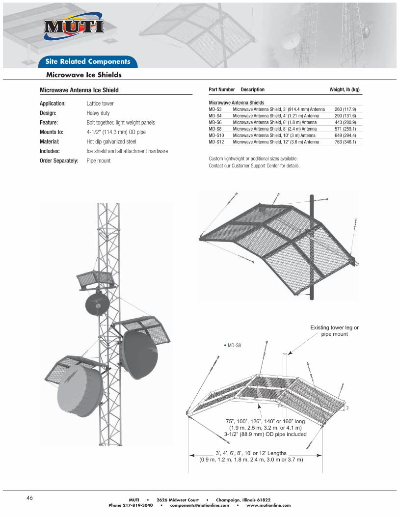
Microwave Antenna Ice Shield
Application: Lattice tower
Design: Heavy duty
Feature: Bolt together, light weight panels
Mounts to: 4-1/2" (114.3 mm) OD pipe
Material: Hot dip galvanized steel
Includes: Ice shield and all attachment hardware
Order Separately: Pipe mount
Existing tower leg or pipe mount
75”, 100”, 126”, 140” or 160” long(1.9 m, 2.5 m, 3.2 m, or 4.1 m)
3-1/2” (88.9 mm) OD pipe included
3’, 4’, 6’, 8’, 10’ or 12’ Lengths(0.9 m, 1.2 m, 1.8 m, 2.4 m, 3.0 m or 3.7 m)
Part Number Description Weight, lb (kg) Microwave Antenna ShieldsMD-S3 Microwave Antenna Shield, 3' (914.4 mm) Antenna 260 (117.9)MD-S4 Microwave Antenna Shield, 4' (1.21 m) Antenna 290 (131.6)MD-S6 Microwave Antenna Shield, 6' (1.8 m) Antenna 443 (200.9)MD-S8 Microwave Antenna Shield, 8' (2.4 m) Antenna 571 (259.1)MD-S10 Microwave Antenna Shield, 10' (3 m) Antenna 649 (294.4)MD-S12 Microwave Antenna Shield, 12' (3.6 m) Antenna 763 (346.1)
Custom lightweight or additional sizes available. Contact our Customer Support Center for details.
MD-S8
Site Related Components
Andrew Solutions www.commscope.com/andrew 47
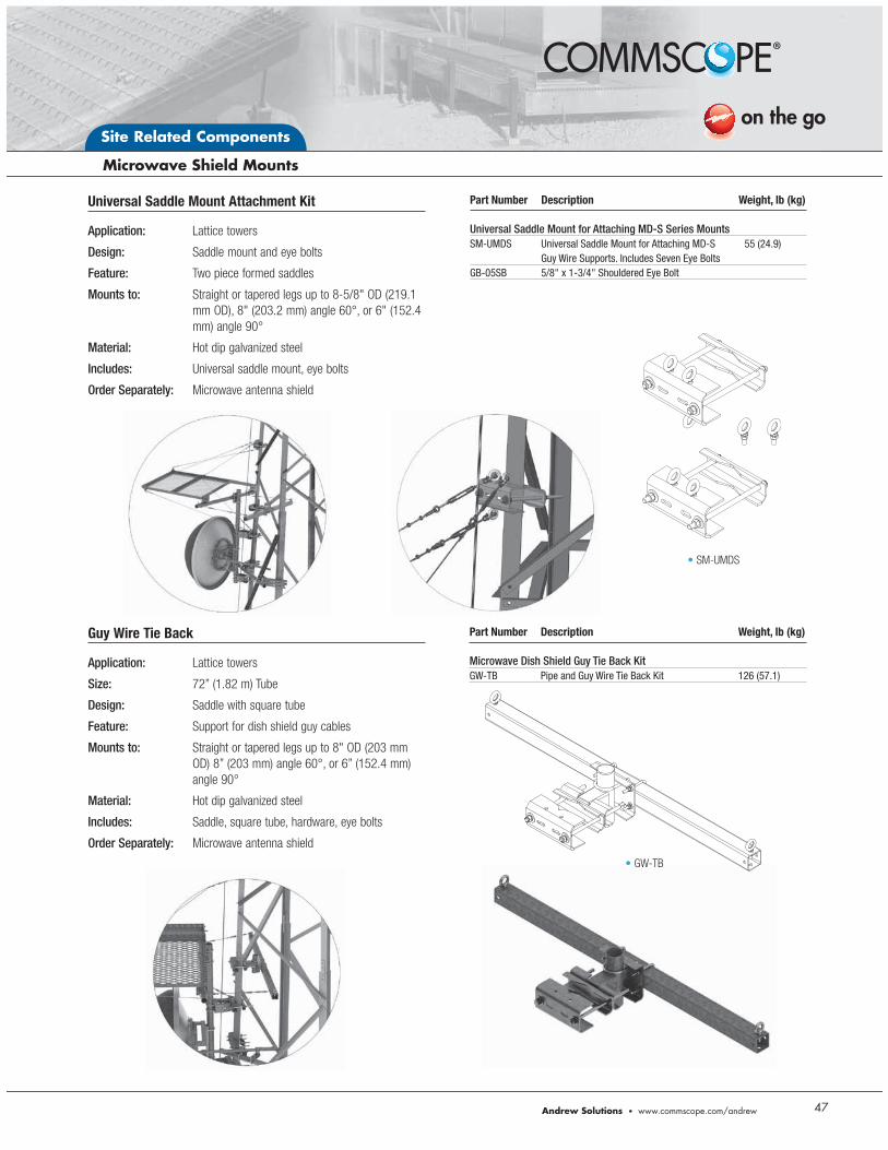
Universal Saddle Mount Attachment Kit
Application: Lattice towers
Design: Saddle mount and eye bolts
Feature: Two piece formed saddles
Mounts to: Straight or tapered legs up to 8-5/8" OD (219.1 mm OD), 8" (203.2 mm) angle 60°, or 6" (152.4 mm) angle 90°
Material: Hot dip galvanized steel
Includes: Universal saddle mount, eye bolts
Order Separately: Microwave antenna shield
Part Number Description Weight, lb (kg) Universal Saddle Mount for Attaching MD-S Series MountsSM-UMDS Universal Saddle Mount for Attaching MD-S 55 (24.9) Guy Wire Supports. Includes Seven Eye BoltsGB-05SB 5/8" x 1-3/4" Shouldered Eye Bolt
SM-UMDS
Guy Wire Tie Back
Application: Lattice towers
Size: 72” (1.82 m) Tube
Design: Saddle with square tube
Feature: Support for dish shield guy cables
Mounts to: Straight or tapered legs up to 8" OD (203 mm OD) 8” (203 mm) angle 60°, or 6” (152.4 mm) angle 90°
Material: Hot dip galvanized steel
Includes: Saddle, square tube, hardware, eye bolts
Order Separately: Microwave antenna shield
Part Number Description Weight, lb (kg) Microwave Dish Shield Guy Tie Back KitGW-TB Pipe and Guy Wire Tie Back Kit 126 (57.1)
GW-TB
Site Related Components
48
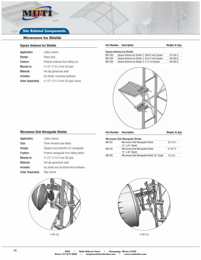
Part Number Description Weight, lb (kg) Square Antenna Ice ShieldsMD-SQ2 Square Antenna Ice Shield, 2' (609.5 mm) Square 125 (56.7)MD-SQ3 Square Antenna Ice Shield, 3' (914.4 mm) Square 150 (68.0)MD-SQ4 Square Antenna Ice Shield, 4' (1.21 m) Square 190 (86.2)
Square Antenna Ice Shields
Application: Lattice towers
Design: Heavy duty
Feature: Protects antenna from falling ice
Mounts to: 4-1/2" (114.3 mm) OD pipe
Material: Hot dip galvanized steel
Includes: Ice shield, mounting hardware
Order Separately: 4-1/2" (114.3 mm) OD pipe mount
MD-IS2 MD-IS4
Microwave Dish Waveguide Shields
Application: Lattice towers
Size: Three versions (see table)
Design: Support and protection for waveguide
Feature: Protects waveguide from falling debris
Mounts to: 4-1/2” (114.3 mm) OD pipe
Material: Hot dip galvanized steel
Includes: Ice shield and all attachment hardware
Order Separately: Pipe mount
Part Number Description Weight, lb (kg) Microwave Dish Waveguide ShieldsMD-IS2 Microwave Dish Waveguide Shield, 42 (19.1) 12" x 24" ShieldMD-IS4 Microwave Dish Waveguide Shield, 61 (27.7) 12" x 48" ShieldMD-WS Microwave Dish Waveguide Shield, 24" Angle 12 (5.4)
Site Related Components
Andrew Solutions www.commscope.com/andrew 49
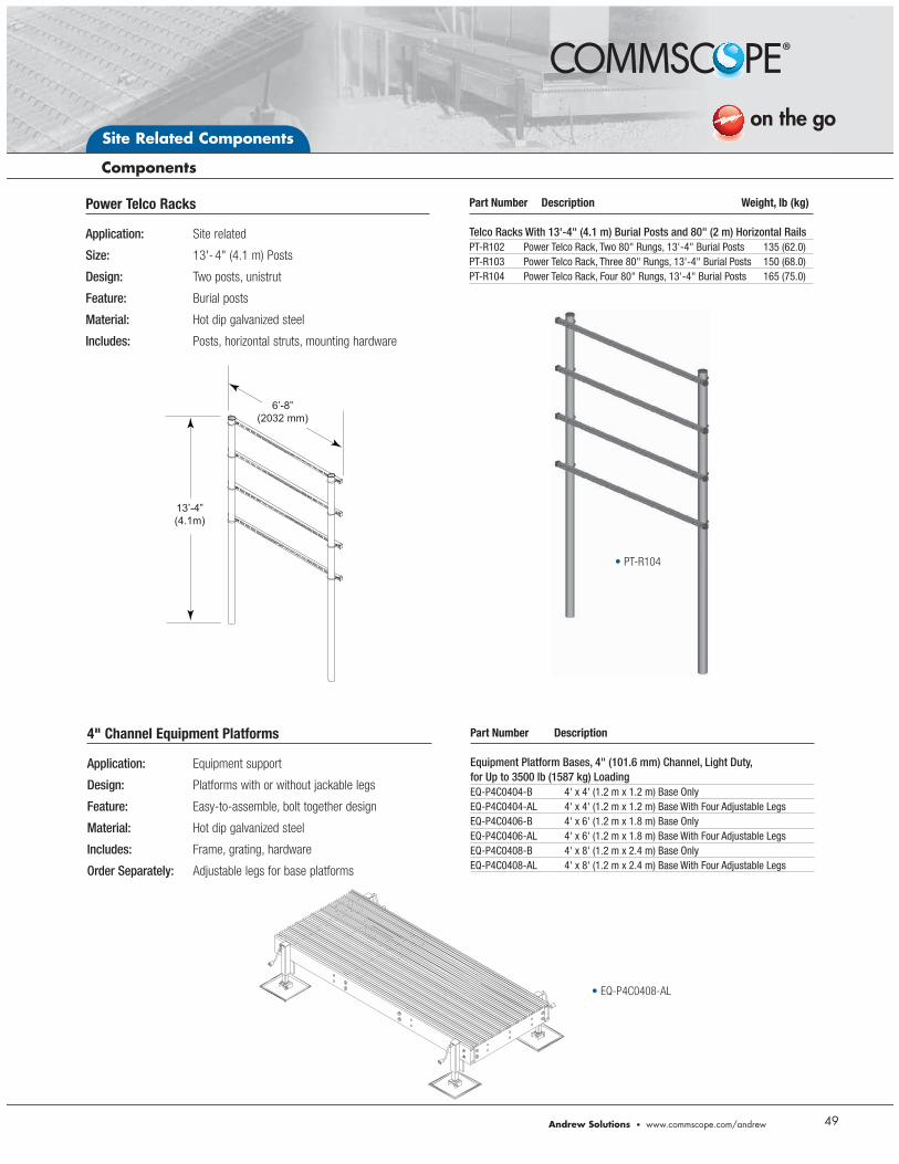
Power Telco Racks
Application: Site related
Size: 13'- 4" (4.1 m) Posts
Design: Two posts, unistrut
Feature: Burial posts
Material: Hot dip galvanized steel
Includes: Posts, horizontal struts, mounting hardware
Part Number Description Weight, lb (kg) Telco Racks With 13'-4" (4.1 m) Burial Posts and 80" (2 m) Horizontal RailsPT-R102 Power Telco Rack, Two 80" Rungs, 13'-4" Burial Posts 135 (62.0)PT-R103 Power Telco Rack, Three 80" Rungs, 13'-4" Burial Posts 150 (68.0)PT-R104 Power Telco Rack, Four 80" Rungs, 13'-4" Burial Posts 165 (75.0)
Part Number Description Equipment Platform Bases, 4" (101.6 mm) Channel, Light Duty, for Up to 3500 lb (1587 kg) LoadingEQ-P4C0404-B 4' x 4' (1.2 m x 1.2 m) Base OnlyEQ-P4C0404-AL 4' x 4' (1.2 m x 1.2 m) Base With Four Adjustable LegsEQ-P4C0406-B 4' x 6' (1.2 m x 1.8 m) Base OnlyEQ-P4C0406-AL 4' x 6' (1.2 m x 1.8 m) Base With Four Adjustable LegsEQ-P4C0408-B 4' x 8' (1.2 m x 2.4 m) Base OnlyEQ-P4C0408-AL 4' x 8' (1.2 m x 2.4 m) Base With Four Adjustable Legs
EQ-P4C0408-AL
4" Channel Equipment Platforms
Application: Equipment support
Design: Platforms with or without jackable legs
Feature: Easy-to-assemble, bolt together design
Material: Hot dip galvanized steel
Includes: Frame, grating, hardware
Order Separately: Adjustable legs for base platforms
13’-4”(4.1m)
6’-8”(2032 mm)
PT-R104
Site Related Components
50
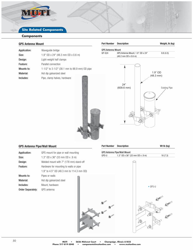
GPS Antenna Mount
Application: Waveguide bridge
Size: 1.9" OD x 24" (48.3 mm OD x 0.6 m)
Design: Light-weight half clamps
Feature: Parallel connection
Mounts to: 1-1/2" to 3-1/2" (38.1 mm to 88.9 mm) OD pipe
Material: Hot dip galvanized steel
Includes: Pipe, clamp halves, hardware
Part Number Description Weight, lb (kg) GPS Antenna MountGP-S24 GPS Antenna Mount, 1.9" OD x 24" 9.8 (4.5) (48.2 mm OD x 0.6 m)
GPS Antenna Pipe/Wall Mount
Application: GPS mount for pipe or wall mounting
Size: 1.3" OD x 36" (33 mm OD x .9 m)
Design: Welded mount with 7" (178 mm) stand-off
Feature: Hardware for mounting to walls or pipe
1.9" to 4.5" OD (48.3 mm to 114.3 mm OD)
Mounts to: Pipes or walls
Material: Hot dip galvanized steel
Includes: Mount, hardware
Order Separately: GPS antenna
Part Number Description Wt lb (kg) GPS Antenna Pipe/Wall MountGPS-U 1.3" OD x 36" (33 mm OD x .9 m) 16 (7.3)
GPS-U
1.9” OD(48.3 mm)
24”(609.6 mm) Existing Pipe
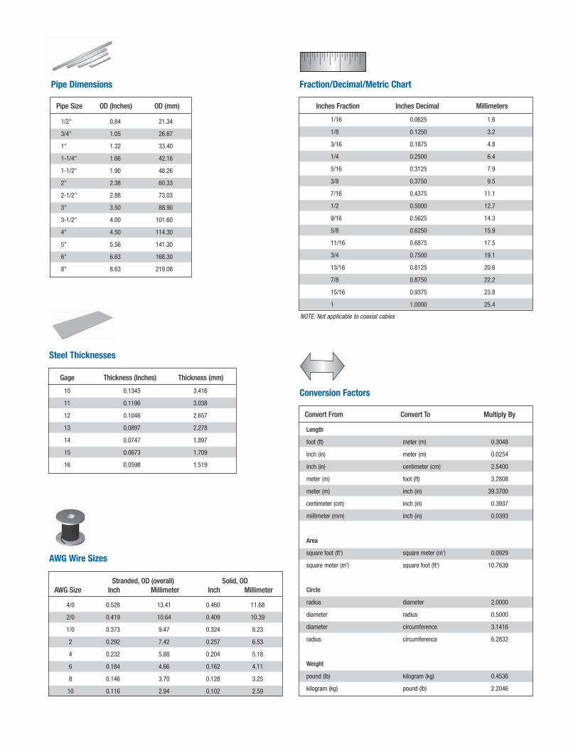
Inches Fraction Inches Decimal Millimeters
Fraction/Decimal/Metric Chart
NOTE: Not applicable to coaxial cables
1/16 0.0625 1.6
1/8 0.1250 3.2
3/16 0.1875 4.8
1/4 0.2500 6.4
5/16 0.3125 7.9
3/8 0.3750 9.5
7/16 0.4375 11.1
1/2 0.5000 12.7
9/16 0.5625 14.3
5/8 0.6250 15.9
11/16 0.6875 17.5
3/4 0.7500 19.1
13/16 0.8125 20.6
7/8 0.8750 22.2
15/16 0.9375 23.8
1 1.0000 25.4
Pipe Size OD (Inches) OD (mm)
Pipe Dimensions
1/2" 0.84 21.34
3/4" 1.05 26.67
1" 1.32 33.40
1-1/4" 1.66 42.16
1-1/2" 1.90 48.26
2" 2.38 60.33
2-1/2" 2.88 73.03
3" 3.50 88.90
3-1/2" 4.00 101.60
4" 4.50 114.30
5" 5.56 141.30
6" 6.63 168.30
8" 8.63 219.08
Gage Thickness (Inches) Thickness (mm)
Steel Thicknesses
10 0.1345 3.416
11 0.1196 3.038
12 0.1046 2.657
13 0.0897 2.278
14 0.0747 1.897
15 0.0673 1.709
16 0.0598 1.519
Stranded, OD (overall) Solid, OD AWG Size Inch Millimeter Inch Millimeter
AWG Wire Sizes
4/0 0.528 13.41 0.460 11.68
2/0 0.419 10.64 0.409 10.39
1/0 0.373 9.47 0.324 8.23
2 0.292 7.42 0.257 6.53
4 0.232 5.88 0.204 5.18
6 0.184 4.66 0.162 4.11
8 0.146 3.70 0.128 3.25
10 0.116 2.94 0.102 2.59
Convert From Convert To Multiply By
Conversion Factors
Length
foot (ft) meter (m) 0.3048
inch (in) meter (m) 0.0254
inch (in) centimeter (cm) 2.5400
meter (m) foot (ft) 3.2808
meter (m) inch (in) 39.3700
centimeter (cm) inch (in) 0.3937
millimeter (mm) inch (in) 0.0393
Area
square foot (ft2) square meter (m2) 0.0929
square meter (m2) square foot (ft2) 10.7639
Circle
radius diameter 2.0000
diameter radius 0.5000
diameter circumference 3.1416
radius circumference 6.2832
Weight
pound (lb) kilogram (kg) 0.4536
kilogram (kg) pound (lb) 2.2046
www.commscope.com/andrewVisit our Web site or contact your local Andrew Solutions representative for more information.
© 2013 CommScope, Inc. All rights reserved.
Andrew Solutions is a trademark of CommScope. All trademarks identified by ® or ™ are registered trademarks or trademarks, respectively, of CommScope. This document is for planning purposes only and is not intended to modify or supplement any specifications or warranties relating to Andrew Solutions products or services.


![Abdullah Al Muti represents Amader Shikkha Kon Pathey [Our Education: Search for Direction] Abdullah Al Muti](https://img.pdfslide.us/doc/110x75/5ea7a26dc04188696b227422/abdullah-al-muti-represents-amader-shikkha-kon-pathey-our-education-search-for.jpg)