Embed Size (px)
Citation preview
MUTAC Review, 9 April 2008 1
MuCOOL and MICE Coupling Magnet Status
Michael A. Green
Lawrence Berkeley Laboratory
Berkeley CA 94720

MUTAC Review, 9 April 2008 2
The ICST Coupling Solenoid Design
Coupling Magnet Cryostat Coupling Magnet Cold Mass
MUTAC Review, 9 April 2008 3
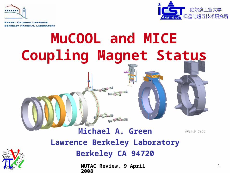
Magnet Progress to Date
• A portion of the superconductor has been delivered. The rest of the conductor is being fabricated.
• Engineering design of the coupling magnet is over 90 percent complete.
• The engineering design of the two ICST test coils is complete.
• The coil winding tooling is complete.
• The first dummy test coil is being wound at ICST.
• The first test coil joints have been fabricated. The joints will be tested in a magnetic field at Berkeley.

MUTAC Review, 9 April 2008 4
ICST Coil Winding Facility
De-spooling and Tensioning Apparatus Coil Winding Apparatus
Winding a Copper Test Coil
MUTAC Review, 9 April 2008 5
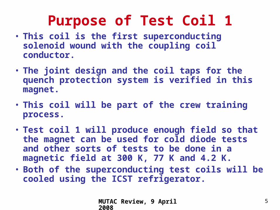
Purpose of Test Coil 1• This coil is the first superconducting solenoid
wound with the coupling coil conductor.
• The joint design and the coil taps for the quench protection system is verified in this magnet.
• This coil will be part of the crew training process.
• Test coil 1 will produce enough field so that the magnet can be used for cold diode tests and other sorts of tests to be done in a magnetic field at 300 K, 77 K and 4.2 K.
• Both of the superconducting test coils will be cooled using the ICST refrigerator.
MUTAC Review, 9 April 2008 6
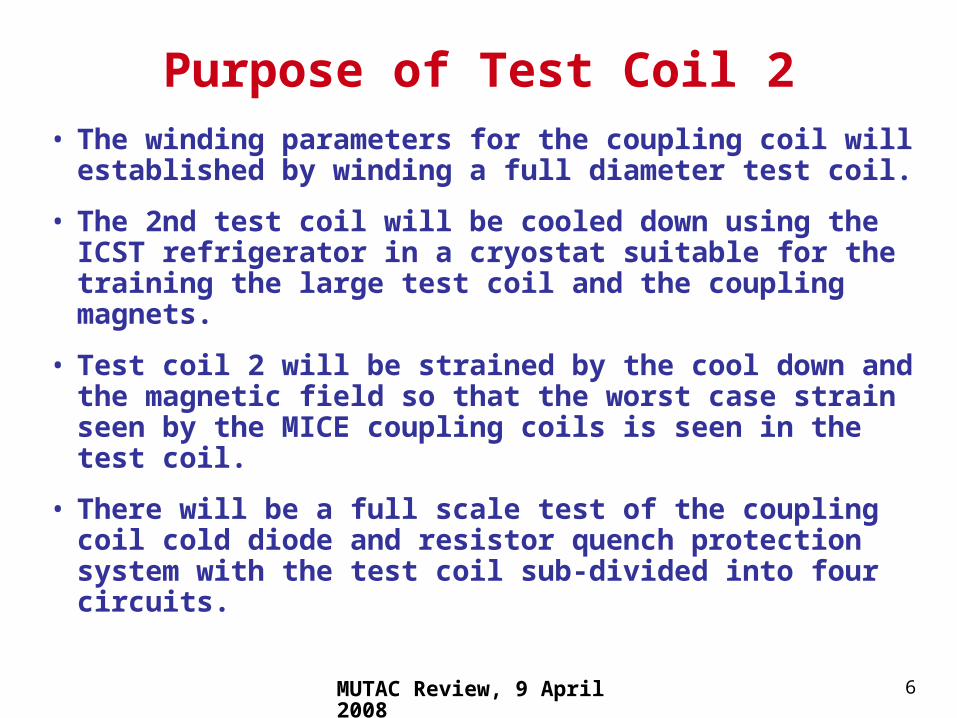
Purpose of Test Coil 2
• The winding parameters for the coupling coil will established by winding a full diameter test coil.
• The 2nd test coil will be cooled down using the ICST refrigerator in a cryostat suitable for the training the large test coil and the coupling magnets.
• Test coil 2 will be strained by the cool down and the magnetic field so that the worst case strain seen by the MICE coupling coils is seen in the test coil.
• There will be a full scale test of the coupling coil cold diode and resistor quench protection system with the test coil sub-divided into four circuits.
MUTAC Review, 9 April 2008 7
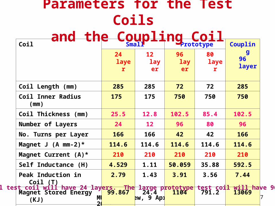
Coil Small Prototype Coupling96 layer24 layer 12 layer 96 layer 80 layer
Coil Length (mm) 285 285 72 72 285
Coil Inner Radius (mm) 175 175 750 750 750
Coil Thickness (mm) 25.5 12.8 102.5 85.4 102.5
Number of Layers 24 12 96 80 96
No. Turns per Layer 166 166 42 42 166
Magnet J (A mm-2)* 114.6 114.6 114.6 114.6 114.6
Magnet Current (A)* 210 210 210 210 210
Self Inductance (H) 4.529 1.11 50.059 35.88 592.5
Peak Induction in Coil (T) 2.79 1.43 3.91 3.56 7.44
Magnet Stored Energy (KJ) 99.867 24.4 1104 791.2 13069
4.2 K Temp. Margin (K) ~3.3 ~3.9 ~2.5 ~2.9 ~0.8
Conductor Len/coil (km) 4.701 2.27 20.299 16.735 ~ 80.118
Parameters for the Test Coils and the Coupling Coil
The small test coil will have 24 layers. The large prototype test coil will have 96 layers.
MUTAC Review, 9 April 2008 8
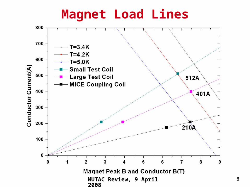
Magnet Load Lines
MUTAC Review, 9 April 2008 9
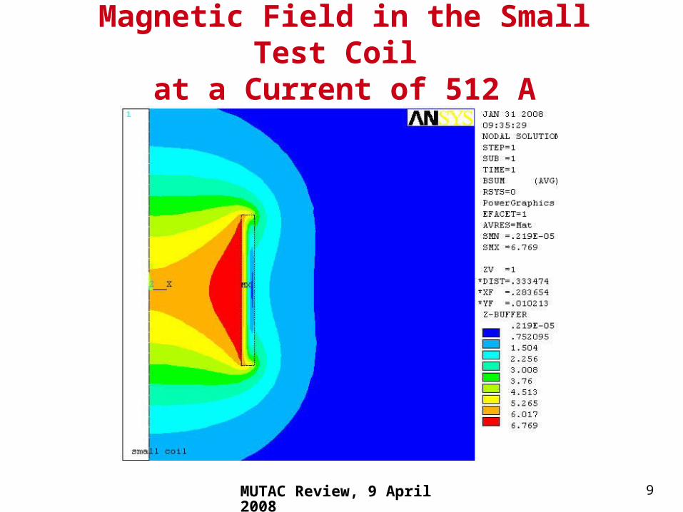
Magnetic Field in the Small Test Coil at a Current of 512 A
MUTAC Review, 9 April 2008 10
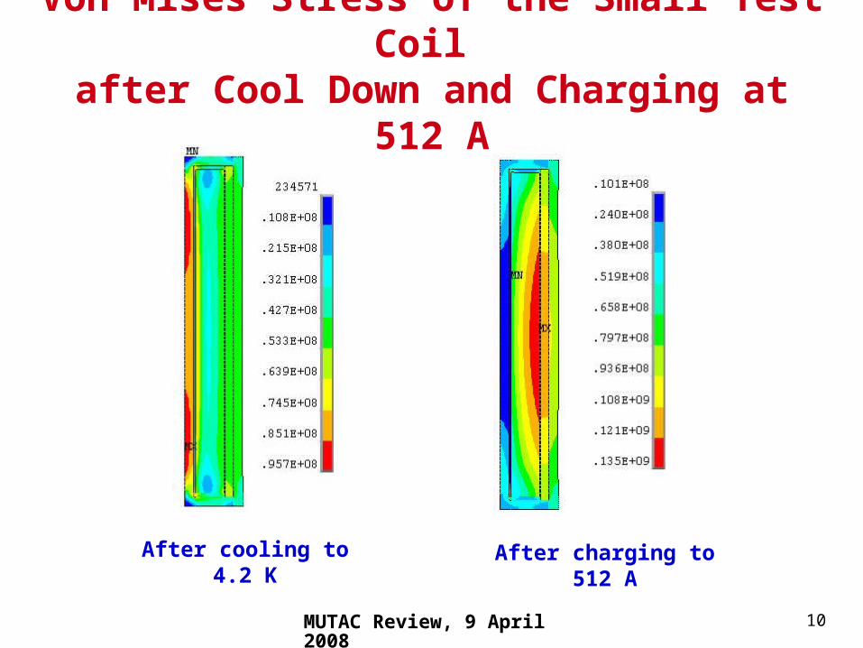
After cooling to 4.2 K After charging to 512 A
Von Mises Stress of the Small Test Coil after Cool Down and Charging at 512 A

MUTAC Review, 9 April 2008 11
Magnetic Field in the Large Test Coil at a Current of 401 A
MUTAC Review, 9 April 2008 12
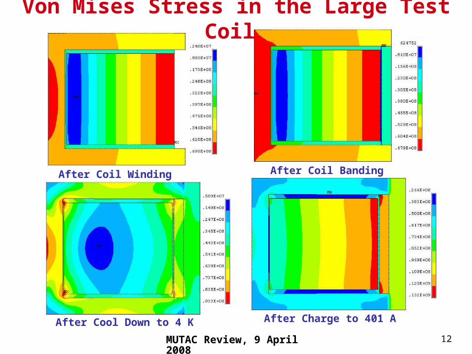
Von Mises Stress in the Large Test Coil
After Coil Winding After Coil Banding
After Cool Down to 4 K After Charge to 401 A

MUTAC Review, 9 April 2008 13
Stress and Deflection Simulations for the 2nd Test Coil (the full diameter test coil)
• Stress and deflection simulations were done on the large test coil. Stress and deflection calculations were done after the magnet was cooled to 4.2 K and powered to 401 A.
• The hoop stress and Von Mises stress is almost the same for the large test coil at 401 A when compared to the coupling coil at 210 A. The radial deflection is also similar. If the large test coil can operate at 400 A, the coupling coil should operate to at least 200 A.
MUTAC Review, 9 April 2008 14
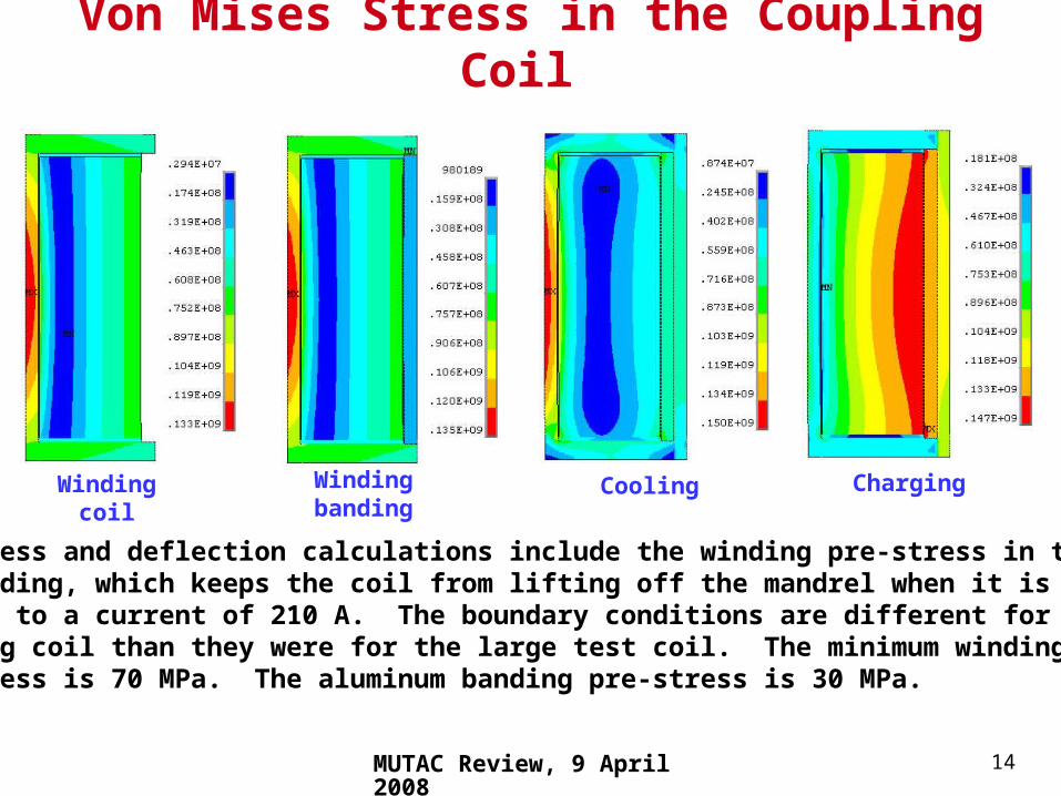
Winding banding Cooling ChargingWinding coil
Von Mises Stress in the Coupling Coil
The stress and deflection calculations include the winding pre-stress in the coiland banding, which keeps the coil from lifting off the mandrel when it is fullycharged to a current of 210 A. The boundary conditions are different for thecoupling coil than they were for the large test coil. The minimum winding Pre-stress is 70 MPa. The aluminum banding pre-stress is 30 MPa.
MUTAC Review, 9 April 2008 15
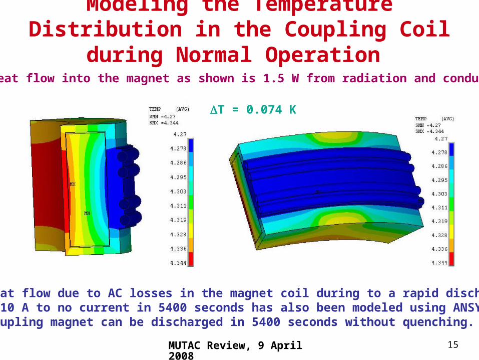
Modeling the Temperature Distribution in the Coupling Coil during Normal Operation
The heat flow into the magnet as shown is 1.5 W from radiation and conduction.
The heat flow due to AC losses in the magnet coil during to a rapid discharge from 210 A to no current in 5400 seconds has also been modeled using ANSYS.The coupling magnet can be discharged in 5400 seconds without quenching.
T = 0.074 K
MUTAC Review, 9 April 2008 16
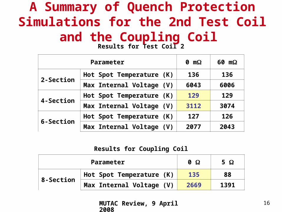
Parameter 0 m 60 m
2-SectionHot Spot Temperature (K) 136 136
Max Internal Voltage (V) 6043 6006
4-SectionHot Spot Temperature (K) 129 129
Max Internal Voltage (V) 3112 3074
6-SectionHot Spot Temperature (K) 127 126
Max Internal Voltage (V) 2077 2043
Parameter 0 5
8-SectionHot Spot Temperature (K) 135 88
Max Internal Voltage (V) 2669 1391
Results for Test Coil 2
Results for Coupling Coil
A Summary of Quench Protection Simulations for the 2nd Test Coil and the Coupling Coil

MUTAC Review, 9 April 2008 17
The ICST set up allows the coupling magnet to be trained rapidly to its full current.
Refrigerator
1500 mm ID Magnet Coil
MUTAC Review, 9 April 2008 18
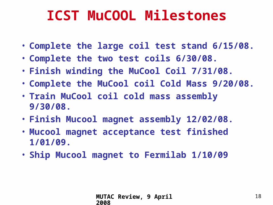
ICST MuCOOL Milestones
• Complete the large coil test stand 6/15/08.• Complete the two test coils 6/30/08.• Finish winding the MuCool Coil 7/31/08.• Complete the MuCool coil Cold Mass 9/20/08.• Train MuCool coil cold mass assembly 9/30/08.• Finish Mucool magnet assembly 12/02/08.• Mucool magnet acceptance test finished 1/01/09.• Ship Mucool magnet to Fermilab 1/10/09
MUTAC Review, 9 April 2008 19
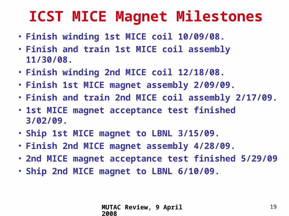
• Finish winding 1st MICE coil 10/09/08.• Finish and train 1st MICE coil assembly 11/30/08.• Finish winding 2nd MICE coil 12/18/08.• Finish 1st MICE magnet assembly 2/09/09.• Finish and train 2nd MICE coil assembly 2/17/09.• 1st MICE magnet acceptance test finished 3/02/09.• Ship 1st MICE magnet to LBNL 3/15/09.• Finish 2nd MICE magnet assembly 4/28/09.• 2nd MICE magnet acceptance test finished 5/29/09• Ship 2nd MICE magnet to LBNL 6/10/09.
ICST MICE Magnet Milestones
MUTAC Review, 9 April 2008 20
Concluding Comments
• The coupling magnet engineering is nearly done, but there may be a few changes in the final design based on what is learned from the two test coils.
• The schedule for the Mucool and MICE magnets is based on things going well. The schedule doesn’t consider unforeseen problems that may be encountered when the MuCool magnet is run with the 1.5 W coolers for the first time.

![MuCool Superconducting Solenoid Quench …...Index Terms— Superconducting solenoid, Magnetic field, Quench, 3D simulations, Test Stand. I. INTRODUCTION HE MUCOOL experiment [1] magnet](https://img.pdfslide.us/doc/110x75/5e92b2bd1d72c02008514bd1/mucool-superconducting-solenoid-quench-index-termsa-superconducting-solenoid.jpg)