Embed Size (px)
Citation preview

MURANG’A COUNTY GOVERNMENT
MURANG’A MUNICIPALITY
TENDER DOCUMENT
FOR
PROPOSED REHABILITATION WORKS TO
CREATE OFFICES FOR THE MURANG’A
MUNICIPALITY
TENDER No. MM/ 002 / 2020-2021
SEPTEMBER 2020
2
PROPOSED REHABILITATION WORKS TO
CREATE OFFICES FOR THE MURANG’A
MUNICIPALITY
CONTENTS AND SIGNATURE PAGES
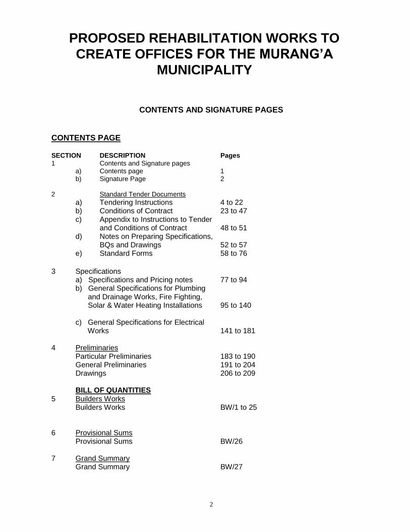
CONTENTS PAGE SECTION DESCRIPTION Pages 1 Contents and Signature pages a) Contents page 1 b) Signature Page 2 2 Standard Tender Documents
a) Tendering Instructions 4 to 22 b) Conditions of Contract 23 to 47 c) Appendix to Instructions to Tender
and Conditions of Contract 48 to 51 d) Notes on Preparing Specifications,
BQs and Drawings 52 to 57 e) Standard Forms 58 to 76
3 Specifications a) Specifications and Pricing notes 77 to 94 b) General Specifications for Plumbing and Drainage Works, Fire Fighting, Solar & Water Heating Installations 95 to 140 c) General Specifications for Electrical Works 141 to 181
4 Preliminaries Particular Preliminaries 183 to 190 General Preliminaries 191 to 204 Drawings 206 to 209
BILL OF QUANTITIES
5 Builders Works Builders Works BW/1 to 25
6 Provisional Sums
Provisional Sums BW/26 7 Grand Summary Grand Summary BW/27
3
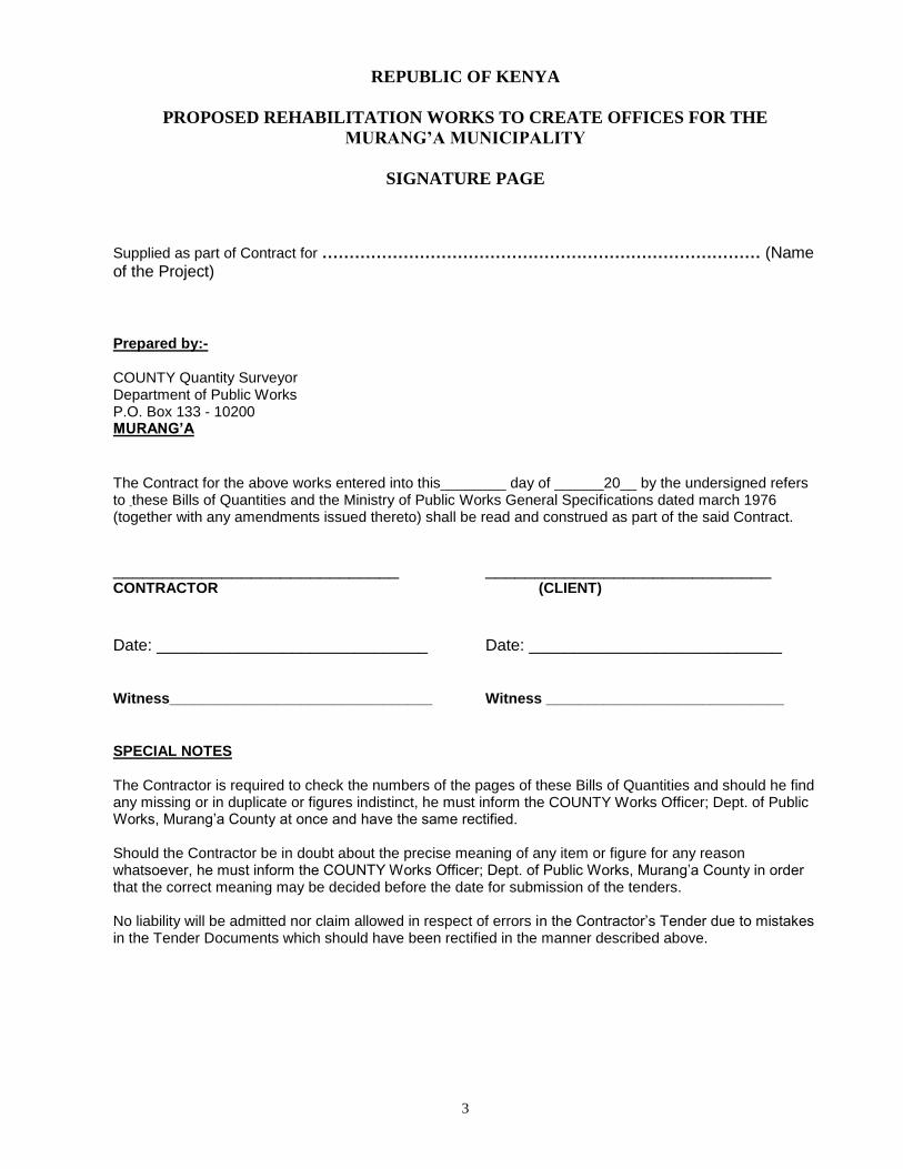
REPUBLIC OF KENYA
PROPOSED REHABILITATION WORKS TO CREATE OFFICES FOR THE
MURANG’A MUNICIPALITY
SIGNATURE PAGE
Supplied as part of Contract for ……………………………………………………………………… (Name of the Project)
Prepared by:- COUNTY Quantity Surveyor Department of Public Works P.O. Box 133 - 10200 MURANG’A
The Contract for the above works entered into this________ day of ______20__ by the undersigned refers to these Bills of Quantities and the Ministry of Public Works General Specifications dated march 1976 (together with any amendments issued thereto) shall be read and construed as part of the said Contract.
_____________________________ _____________________________ CONTRACTOR (CLIENT)
Date: ______________________________ Date: ____________________________ Witness________________________________ Witness _____________________________
SPECIAL NOTES The Contractor is required to check the numbers of the pages of these Bills of Quantities and should he find any missing or in duplicate or figures indistinct, he must inform the COUNTY Works Officer; Dept. of Public Works, Murang’a County at once and have the same rectified. Should the Contractor be in doubt about the precise meaning of any item or figure for any reason whatsoever, he must inform the COUNTY Works Officer; Dept. of Public Works, Murang’a County in order that the correct meaning may be decided before the date for submission of the tenders. No liability will be admitted nor claim allowed in respect of errors in the Contractor’s Tender due to mistakes in the Tender Documents which should have been rectified in the manner described above.

4
REPUBLIC OF KENYA
STANDARD TENDER DOCUMENT
FOR
PROCUREMENT OF WORKS (BUILDING AND ASSOCIATED
CIVIL ENGINEERING WORKS)
PUBLIC PROCUREMENT OVERSIGHT AUTHORITY (PPOA)
P.O. BOX 30007 - 00200 NAIROBI.
(REVISED OCTOBER 2006)
TABLE OF CONTENTS
5
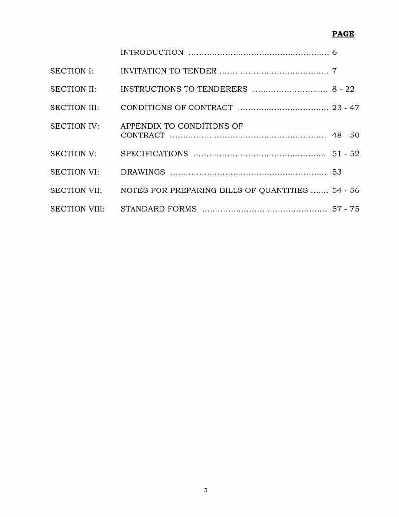
PAGE
INTRODUCTION ……………………………………………… 6
SECTION I: INVITATION TO TENDER …………………………………… 7 SECTION II: INSTRUCTIONS TO TENDERERS ……………………….. 8 - 22
SECTION III: CONDITIONS OF CONTRACT …………………………….. 23 - 47
SECTION IV: APPENDIX TO CONDITIONS OF CONTRACT …………………………………………………… 48 - 50
SECTION V: SPECIFICATIONS …………………………………………… 51 - 52
SECTION VI: DRAWINGS …………………………………………………… 53
SECTION VII: NOTES FOR PREPARING BILLS OF QUANTITIES ……. 54 - 56 SECTION VIII: STANDARD FORMS ………………………………………… 57 - 75
6
INTRODUCTION
1.1 This standard tender document for procurement of works has been
prepared for use by procuring entities in Kenya in the procurement of works (i.e. Buildings and associated Civil Engineering Works).
1.2 The following guidelines should be observed when using the document:-
(a) Specific details should be furnished in the Invitation to tender and in the special conditions of contract (where applicable). The tender document issued to tenderers should not have
blank spaces or options.
(b) The instructions to tenderers and the General Conditions of Contract should remain unchanged. Any necessary amendments to these parts should be made through Appendix to instructions
to tenderers and special conditions of contract respectively. 1.3
(b) Information contained in the invitation to tender shall conform to the data and information in the tender documents to enable
prospective tenderers to decide whether or not to participate in the tender and shall indicate any important tender requirements
(c) The invitation to tender shall be as an advertisement in accordance with the regulations or a letter of invitation addressed to tenderers who have been prequalified following a request for
prequalification.
1.4 The cover of the document shall be modified to include:-
I. Tender number.
II. Tender name. III. Name of procuring entity.
IV. Delete name and address of PPOA.

7
SECTION I INVITATION FOR TENDERS
Tender reference No. (as per tender document)
Tender Name (as per tender document)
1.1 The (procuring entity) invites sealed tenders for the construction of (Brief description of works)
1.2 Interested eligible candidates may obtain further information and
inspect tender documents (and additional copies) at (name, address and physical location of the procuring entity including relevant office)
during normal working hours. 1.3 A complete set of tender documents may be obtained by interested
candidates upon payment of a non-refundable fees of (Amount) in cash or Bankers Cheque payable to (According officer)
1.4 Prices quoted should be net inclusive of all taxes, must be in Kenya
shillings and shall remain valid for ( ) days from the closing date of
tender.
1.5 Completed tender documents are to be enclosed in plain sealed envelopes marked with Tender name and reference number and deposited in the Tender Box at (address and location) or to be
addressed to (procurement entity’s name and address) so as to be received on or before (day, date and time).
1.6 Tenders will be opened immediately thereafter in the presence of the candidates or their representatives who choose to attend at (Address and Appropriate Officer)
________________________________
For (Accounting Officer/Procuring Entity)
8
SECTION II
INSTRUCTIONS TO TENDERERS
TABLE OF CONTENTS PAGE
CLAUSE PAGE
1. General …………………………………………………. 9 - 12 2. Tender Documents ………………………………… 12 - 13
3. Preparation of Tenders ………………………………… 13 - 16
4. Submission of Tenders ………………………………… 16 - 17
5. Tende r Opening and Evaluation ……………………… 17 - 20 6. Award of Contract ………………………………………… 20 - 22
9
INSTRUCTIONS TO TENDERERS.
1. 1. General/Eligibility/Qualifications/Joint venture/Cost of tendering
1.1 The Employer as defined in the Appendix to Conditions of Contract invites tenders for Works Contract as described in the tender documents. The successful tenderer will be expected to complete
the Works by the Intended Completion Date specified in the tender documents.
1.2 All tenderers shall provide the Qualification Information, a
statement that the tenderer (including all members of a joint venture
and subcontractors) is not associated, or has not been associated in the past, directly or indirectly, with the Consultant or any other
entity that has prepared the design, specifications, and other documents for the project or being proposed as Project Manager for the Contract. A firm that has been engaged by the Employer to
provide consulting services for the preparation or supervision of the Works, and any of its affiliates, shall not be eligible to tender.
1.3 All tenderers shall provide in the Form of Tender and Qualification Information, a preliminary description of the proposed work method
and schedule, including drawings and charts, as necessary.
1.4 In the event that pre-qualification of potential tenderers has been
undertaken, only tenders from pre-qualified tenderers will be considered for award of Contract. These qualified tenderers should submit with their tenders any information updating their original
pre-qualification applications or, alternatively, confirm in their tenders that the originally submitted pre-qualification information
remains essentially correct as of the date of tender submission.
1.5 Where no pre-qualification of potential tenderers has been done, all
tenderers shall include the following information and documents with their tenders , unless otherwise stated:
(a) copies of original documents defining the constitution or legal
status, place of registration, and principal place of business;
written power of attorney of the signatory of the tender to commit the tenderer:
(b) total monetary value of construction work performed for each of the last five years:
(c) experience in works of a similar nature and size for each of the
last five years, and details of work under way or contractually

10
committed; and names and addresses of clients who may be contacted for further information on these contracts;
(d) major items of construction equipment proposed to carry out
the Contract and an undertaking that they will be available for
the Contract.
(e) qualifications and experience of key site management and
technical personnel proposed for the Contract and an undertaking that they shall be available for the Contract.
(f) reports on the financial standing of the tenderer, such as
profit and loss statements and auditor’s reports for the past
five years;
(g) evidence of adequacy of working capital for this Contract (access to line(s) of credit and availability of other financial resources);
(h) authority to seek references from the tenderer’s bankers;
(i) information regarding any litigation, current or during the last five years, in which the tenderer is involved, the parties
concerned and disputed amount; and
(j) proposals for subcontracting components of the Works
amounting to more than 10 percent of the Contract Price.
1.6 Tenders submitted by a joint venture of two or more firms as
partners shall comply with the following requirements, unless otherwise stated:
(a) the tender shall include all the information listed in clause 1.5
above for each joint venture partner;
(b) the tender shall be signed so as to be legally binding on all
partners;
(c) all partners shall be jointly and severally liable for the
execution of the Contract in accordance with the Contract terms;
(d) one of the partners will be nominated as being in charge, authorised to incur liabilities, and receive instructions for and
on behalf of all partners of the joint venture; and
(e) the execution of the entire Contract, including payment,
11
shall be done exclusively with the partner in charge.
1.7 To qualify for award of the Contract, tenderers shall meet the following minimum qualifying criteria;
(a) annual volume of construction work of at least 2.5 times the
estimated annual cashflow for the Contract;
(b) experience as main contractor in the construction of at least
(c) two works of a nature and complexity equivalent to the Works
over the last 10 years (to comply with this requirement, works cited should be at least 70 percent complete);
(d) proposals for the timely acquisition (own, lease, hire, etc.) of the
essential equipment listed as required for the Works;
(e) a Contract manager with at least five years’ experience in works
of an equivalent nature and volume, including no less than three
years as Manager; and
(f) liquid assets and/or credit facilities, net of other contractual commitments and exclusive of any advance payments which may be made under the Contract, of no less than 4 months of the
estimated payment flow under this Contract. 1.8 The figures for each of the partners of a joint venture shall be added
together to determine the tenderer’s compliance with the minimum qualifying criteria of clause 1.7 (a) and (e); however, for a joint
venture to qualify, each of its partners must meet at least 25 percent of minimum criteria 1.7 (a), (b) and (e) for an individual tenderer, and the partner in charge at least 40 percent of those minimum
criteria. Failure to comply with this requirement will result in rejection of the joint venture’s tender. Subcontractors’ experience
and resources will not be taken into account in determining the tenderer’s compliance with the qualifying criteria, unless otherwise stated.
1.9 Each tenderer shall submit only one tender, either individually or as
a partner in a joint venture. A tenderer who submits or participates
in more than one tender (other than as a subcontractor or in cases of alternatives that have been permitted or requested) will cause all
the proposals with the tenderer’s participation to be disqualified.
1.10 The tenderer shall bear all costs associated with the preparation and
12
submission of his tender, and the Employer will in no case be responsible or liable for those costs.
1.11 The tenderer, at the tenderer’s own responsibility and risk, is
encouraged to visit and examine the Site of the Works and its surroundings, and obtain all information that may be necessary for preparing the tender and entering into a contract for construction of
the Works. The costs of visiting the Site shall be at the tenderer’s own expense.
1.12 The procuring entity’s employees, committee members, board
members and their relative (spouse and children) are not eligible to
participate in the tender.
1.13 The price to be changed for the tender document shall not exceed Kshs.5,000/=
1.14 The procuring entity shall allow the tenderer to review the tender document free of charge before purchase.
2. Tender Documents
2.1 The complete set of tender documents comprises the documents
listed below and any addenda issued in accordance with Clause 2.4.
(a) These Instructions to Tenderers (b) Form of Tender and Qualification Information
(c) Conditions of Contract (d) Appendix to Conditions of Contract
(e) Specifications (f) Drawings (g) Bills of Quantities
(h) Forms of Securities
2.2 The tenderer shall examine all Instructions, Forms to be filled and Specifications in the tender documents. Failure to furnish all information required by the tender documents, or submission of a
tender not substantially responsive to the tendering documents in every respect will be at the tenderer’s risk and may result in rejection of his tender.
2.3 A prospective tenderer making an inquiry relating to the tender
documents may notify the Employer in writing or by cable, telex or facsimile at the address indicated in the letter of invitation to tender. The Employer will only respond to requests for clarification received

13
earlier than seven days prior to the deadline for submission of tenders. Copies of the Employer’s response will be forwarded to all
persons issued with tendering documents, including a description of the inquiry, but without identifying its source.
2.4 Before the deadline for submission of tenders, the Employer may
modify the tendering documents by issuing addenda. Any
addendum thus issued shall be part of the tendering documents and shall be communicated in writing or by cable, telex or facsimile to all tenderers. Prospective tenderers shall acknowledge receipt of each
addendum in writing to the Employer.
2.5 To give prospective tenderers reasonable time in which to take an addendum into account in preparing their tenders, the Employer shall extend, as necessary, the deadline for submission of tenders,
in accordance with Clause 4.2 here below.
3. Preparation of Tenders
3.1 All documents relating to the tender and any correspondence shall be in English language.
3.2 The tender submitted by the tenderer shall comprise the following:
(a) These Instructions to Tenderers, Form of Tender, Conditions
of Contract, Appendix to Conditions of Contract and
Specifications;
(b) Tender Security;
(c) Priced Bill of Quantities ;
(d) Qualification Information Form and Documents;
(e) Alternative offers where invited; and
(f) Any other materials required to be completed and submitted
by the tenderers.
3.3 The tenderer shall fill in rates and prices for all items of the Works described in the Bill of Quantities. Items for which no rate or price is entered by the tenderer will not be paid for when executed and
14
shall be deemed covered by the other rates and prices in the Bill of Quantities. All duties, taxes, and other levies payable by the
Contractor under the Contract, or for any other cause relevant to the Contract, as of 30 days prior to the deadline for submission of
tenders, shall be included in the tender price submitted by the tenderer.
3.4 The rates and prices quoted by the tenderer shall only be subject to adjustment during the performance of the Contract if provided for in the Appendix to Conditions of Contract and provisions made in the
Conditions of Contract.
3.5 The unit rates and prices shall be in Kenya Shillings.
3.6 Tenders shall remain valid for a period of sixty (60) days from the date of submission. However in exceptional circumstances, the Employer may request that the tenderers extend the period of
validity for a specified additional period. The request and the tenderers’ responses shall be made in writing. A tenderer may refuse the request without forfeiting the Tender Security. A tenderer
agreeing to the request will not be required or permitted to otherwise modify the tender, but will be required to extend the validity of
Tender Security for the period of the extension, and in compliance with Clause 3.7 - 3.11 in all respects.
3.7 The tenderer shall furnish, as part of the tender, a Tender Security in the amount and form specified in the appendix to invitation to tenderers. This shall be in the amount not exceeding 2 percent of
the tender price
3.8 The format of the Tender Security should be in accordance with the
form of Tender Security included in Section G - Standard forms or
any other form acceptable to the Employer . Tender Security shall be valid for 30 days beyond the validity of the tender.
3.9 Any tender not accompanied by an acceptable Tender Security shall
be rejected. The Tender Security of a joint venture must define as “Tenderer” all joint venture partners and list them in the following manner: a joint venture consisting of”…………”,”…………”,and
“…………”.
3.10 The Tender Securities of unsuccessful tenderers will be returned
within 28 days of the end of the tender validity period specified in
15
Clause 3.6.
3.11 The Tender Security of the successful tenderer will be discharged
when the tenderer has signed the Contract Agreement and furnished the required Performance Security.
3.12 The Tender Security may be forfeited
(a) if the tenderer withdraws the tender after tender opening during the period of tender validity;
(b) if the tenderer does not accept the correction of the tender price, pursuant to Clause 5.7;
(c) in the case of a successful tenderer, if the tenderer fails within
the specified time limit to
(i) sign the Agreement, or
(ii) furnish the required Performance Security.
3.13 Tenderers shall submit offers that comply with the requirements of
the tendering documents, including the basic technical design as
indicated in the Drawings and Specifications. Alternatives will not be considered, unless specifically allowed in the invitation to tender.
If so allowed, tenderers wishing to offer technical alternatives to the requirements of the tendering documents must also submit a tender that complies with the requirements of the tendering documents,
including the basic technical design as indicated in the Drawings and Specifications. In addition to submitting the basic tender, the
tenderer shall provide all information necessary for a complete evaluation of the alternative, including design calculations, technical specifications, breakdown of prices, proposed construction methods
and other relevant details. Only the technical alternatives, if any, of the lowest evaluated tender conforming to the basic technical requirements shall be considered.
3.14 The tenderer shall prepare one original of the documents comprising
the tender documents as described in Clause 3.2 of these Instructions to Tenderers, bound with the volume containing the Form of Tender,
16
and clearly marked “ORIGINAL”. In addition, the tenderer shall submit copies of the tender, in the number specified in the invitation
to tender, and clearly marked as “COPIES”. In the event of discrepancy between them, the original shall prevail.
3.15 The original and all copies of the tender shall be typed or written in
indelible ink and shall be signed by a person or persons duly
authorised to sign on behalf of the tenderer, pursuant to Clause 1.5 (a) or 1.6 (b), as the case may be. All pages of the tender where alterations or additions have been made shall be initialled by the
person or persons signing the tender.
3.16 Clarification of tenders shall be requested by the tenderer to be received by the procuring entity not later than 7 days prior to the deadline for submission of tenders.
3.17 The procuring entity shall reply to any clarifications sought by the
tenderer within 3 days of receiving the request to enable the tenderer to make timely submission of its tender.
3.18 The tender security shall be in the amount of 0.5 – 2 per cent of the tender price.
4. Submission of Tenders
4.1 The tenderer shall seal the original and all copies of the tender in two inner envelopes and one outer envelope, duly marking the inner envelopes as “ORIGINAL” and “COPIES” as appropriate. The inner
and outer envelopes shall: 10
(a) be addressed to the Employer at the address provided in the invitation to tender;
(b) bear the name and identification number of the Contract as defined in the invitation to tender; and
(c) provide a warning not to open before the specified time and
date for tender opening.
4.2 Tenders shall be delivered to the Employer at the address specified
above not later than the time and date specified in the invitation to
tender. However, the Employer may extend the deadline for submission of tenders by issuing an amendment in accordance with
Sub-Clause 2.5 in which case all rights and obligations of the Employer and the tenderers previously subject to the original deadline will then be subject to the new deadline.
17
4.3 Any tender received after the deadline prescribed in clause 4.2 will
be returned to the tenderer un-opened.
4.4 Tenderers may modify or withdraw their tenders by giving notice in writing before the deadline prescribed in clause 4.2. Each tenderer’s modification or withdrawal notice shall be prepared, sealed, marked,
and delivered in accordance with clause 3.13 and 4.1, with the outer and inner envelopes additionally marked “MODIFICATION”and “WITHDRAWAL”, as appropriate. No tender may be modified after
the deadline for submission of tenders.
4.5 Withdrawal of a tender between the deadline for submission of tenders and the expiration of the period of tender validity specified in the invitation to tender or as extended pursuant to Clause 3.6
may result in the forfeiture of the Tender Security pursuant to Clause 3.11.
4.6 Tenderers may only offer discounts to, or otherwise modify the
prices of their tenders by submitting tender modifications in
accordance with Clause 4.4 or be included in the original tender submission.
5. Tender Opening and Evaluation
5.1 The tenders will be opened by the Employer, including modifications made pursuant to Clause 4.4, in the presence of the tenderers’ representatives who choose to attend at the time and in the place
specified in the invitation to tender. Envelopes marked “WITHDRAWAL” shall be opened and read out first. Tenderers’ and
Employer’s representatives who are present during the opening shall sign a register evidencing their attendance.
5.2 The tenderers’ names, the tender prices, the total amount of each tender and of any alternative tender (if alternatives have been
requested or permitted), any discounts, tender modifications and withdrawals, the presence or absence of Tender Security, and such other details as may be considered appropriate, will be announced
by the Employer at the opening. Minutes of the tender opening, including the information disclosed to those present will be prepared by the Employer.
5.3 Information relating to the examination, clarification, evaluation,
and comparison of tenders and recommendations for the award of Contract shall not be disclosed to tenderers or any other persons not officially concerned with such process until the award to the
18
successful tenderer has been announced. Any effort by a tenderer to influence the Employer’s officials, processing of tenders or award
decisions may result in the rejection of his tender.
5.4 To assist in the examination, evaluation, and comparison of tenders, the Employer at his discretion, may ask any tenderer for clarification of the tender, including breakdowns of unit rates. The request for
clarification and the response shall be in writing or by cable, telex or facsimile but no change in the price or substance of the tender shall be sought, offered, or permitted except as required to confirm the
correction of arithmetic errors discovered in the evaluation of the tenders in accordance with Clause 5.7.
5.5 Prior to the detailed evaluation of tenders, the Employer will
determine whether each tender (a) meets the eligibility criteria
defined in Clause 1.7;(b) has been properly signed; (c) is accompanied by the
required securities; and (d) is substantially responsive to the requirements of the tendering documents. A substantially responsive tender is one which conforms to all the terms, conditions
and specifications of the tendering documents, without material deviation or reservation. A material deviation or reservation is one (a) which
affects in any substantial way the scope, quality, or performance of the works; (b) which limits in any substantial way, inconsistent with
the tendering documents, the Employer’s rights or the tenderer’s obligations under the Contract; or (c) whose rectification would affect unfairly the competitive position of other tenderers presenting
substantially responsive tenders.
5.6 If a tender is not substantially responsive, it will be rejected, and may not subsequently be made responsive by correction or withdrawal of the nonconforming deviation or reservation.
5.7 Tenders determined to be substantially responsive will be checked
for any arithmetic errors. Errors will be corrected as follows:
(a) where there is a discrepancy between the amount in figures
and the amount in words, the amount in words will prevail; and
(b) where there is a discrepancy between the unit rate and the line item total resulting from multiplying the unit rate by the
quantity, the unit rate as quoted will prevail, unless in the opinion of the Employer, there is an obvious typographical error, in which case the adjustment will be made to the entry
19
containing that error.
(c) In the event of a discrepancy between the tender amount as stated in the Form of Tender and the corrected tender figure in
the main summary of the Bill of Quantities, the amount as stated in the Form of Tender shall prevail.
(d) The Error Correction Factor shall be computed by expressing the difference between the tender amount and the corrected tender sum as a percentage of the corrected Builder’s Work
(i.e. Corrected tender sum less P.C. and Provisional Sums)
(e) The Error Correction Factor shall be applied to all Builder’s Work (as a rebate or addition as the case may be) for the purposes of valuations for Interim Certificates and valuation of
variations.
(f) the amount stated in the tender will be adjusted in accordance with the above procedure for the correction of errors and, with concurrence of the tenderer, shall be considered as binding
upon the tenderer. If the tenderer does not accept the corrected amount, the tender may be rejected and the Tender Security may be forfeited in accordance with clause 3.11.
5.8 The Employer will evaluate and compare only the tenders
determined to be substantially responsive in accordance with Clause 5.5.
5.9 In evaluating the tenders, the Employer will determine for each tender the evaluated tender price by adjusting the tender price as
follows:
(a) making any correction for errors pursuant to clause 5.7;
(b) excluding provisional sums and the provision, if any, for
contingencies in the Bill of Quantities, but including Dayworks where priced competitively.
(c) making an appropriate adjustment for any other acceptable variations, deviations, or alternative offers submitted in accordance with clause 3.12; and
(d) making appropriate adjustments to reflect discounts or other
price modifications offered in accordance with clause 4.6 5.10 The Employer reserves the right to accept or reject any variation,
20
deviation, or alternative offer. Variations, deviations, and alternative offers and other factors which are in excess of the requirements of
the tender documents or otherwise result in unsolicited benefits for the Employer will not be taken into account in tender evaluation.
5.11 The tenderer shall not influence the Employer on any matter relating
to his tender from the time of the tender opening to the time the Contract is awarded. Any effort by the Tenderer to influence the Employer or his employees in his decision on tender evaluation,
tender comparison or Contract award may result in the rejection of the tender.
5.12 Firms incorporated in Kenya where indigenous Kenyans own 51% or
more of the share capital shall be allowed a 10% preferential bias
provided that they do not sub-contract work valued at more than 50% of the Contract Price excluding Provisional Sums to an
non-indigenous sub-contractor.
6. Award of Contract
6.1 Subject to Clause 6.2, the award of the Contract will be made to the
tenderer whose tender has been determined to be substantially
responsive to the tendering documents and who has offered the lowest evaluated tender price, provided that such tenderer has been
determined to be (a) eligible in accordance with the provision of Clauses 1.2, and (b) qualified in accordance with the provisions of clause 1.7 and 1.8.
6.2 Notwithstanding clause 6.1 above, the Employer reserves the right to accept or reject any tender, and to cancel the tendering process and
reject all tenders, at any time prior to the award of Contract, without thereby incurring any liability to the affected tenderer or tenderers
or any obligation to inform the affected tenderer or tenderers of the grounds for the action.
6.3 The tenderer whose tender has been accepted will be notified of the award prior to expiration of the tender validity period in writing or by cable, telex or facsimile. This notification (hereinafter and in all
Contract documents called the “Letter of Acceptance”) will state the sum (hereinafter and in all Contract documents called the “Contract
Price”)that the Employer will pay the Contractor in consideration of the execution, completion, and maintenance of the Works by the Contractor as prescribed by the Contract. At the same time the other
21
tenderers shall be informed that their tenders have not been successful.
The contract shall be formed on the parties signing the contract.
6.4 The Agreement will incorporate all agreements between the
Employer and the successful tenderer. Within 14 days of receipt the
successful tenderer will sign the Agreement and return it to the Employer.
6.5 Within 21 days after receipt of the Letter of Acceptance, the successful tenderer shall deliver to the Employer a Performance
Security in the amount stipulated in the Appendix to Conditions of Contract and in the form stipulated in the Tender documents. The Performance Security shall be in the amount and specified form
6.6 Failure of the successful tenderer to comply with the requirements
of clause 6.5 shall constitute sufficient grounds for cancellation of the award and forfeiture of the Tender Security.
6.7 Upon the furnishing by the successful tenderer of the Performance Security, the Employer will promptly notify the other tenderers that their tenders have been unsuccessful.
6.8 Preference where allowed in the evaluation of tenders shall not be
allowed for contracts not exceeding one year (12 months)
6.9 The tender evaluation committee shall evaluate the tender within 30
days of the validity period from the date of opening the tender.
6.10 The parties to the contract shall have it signed within 30 days from
the date of notification of contract award unless there is an administrative review request.
6.11 Contract price variations shall not be allowed for contracts not
exceeding one year (12 months)
6.12 Where contract price variation is allowed, the valuation shall not
exceed 15% of the original contract price.
6.13 Price variation request shall be processed by the procuring entity
within 30 days of receiving the request.
6.14 The procuring entity may at any time terminate procurement
proceedings before contract award and shall not be liable to any person for the termination.
6.15 The procuring entity shall give prompt notice of the termination to
the tenderers and on request give its reasons for termination within
22
14 days of receiving the request from any tenderer.
6.16 A tenderer who gives false information in the tender document about its qualification or who refuses to enter into a contract after
notification of contract award shall be considered for debarment from participating in future public procurement.
7. Corrupt and Fraudulent practices
7.1 The procuring entity requires that tenderers observe the highest
standards of ethics during procurement process and execution of contracts. A tenderer shall sign a declaration that he has not and
will not be involved in corrupt and fraudulent practices.
23
SECTION III CONDITIONS OF CONTRACT
Table of Contents
1 Definitions ………………………………………………… 25
2 Interpretation……………………………………………… 27
3 Language and Law ………………………………………… 28
4 Project Manager’s Decisions……………………………… 28
5 Delegation………………………………………………… 28
6 Communications ………………………………………… 28
7 Sub Contracting ………………………………………… 28
8 Other Contractors ……………………………………… 28
9 Personnel ………………………………………………… 29
10 Works……………………………………………………… 29
11 Safety and temporary works ……………………………… 29
12 Discoveries ………………………………………………… 29
13 Work Programme ………………………………………… 30
14 Possession of site ………………………………………… 30
15 Access to site …………………………………………… 30
16 Instructions ……………………………………………… 30
17 Extension or Acceleration of completion date ………… 30
18 Management Meetings ………………………………… 31
19 Early Warning …………………………………………… 31
20 Defects …………………………………………………… 32
21 Bills of Quantities ………………………………………… 32
22 Variations ………………………………………………… 33
23 Payment certificates, currency of payments and
Advance Payments ……………………………………… 34
24 Compensation events …………………………………… 36
25 Price Adjustment ………………………………………… 38
26 Retention ………………………………………………… 39
27 Liquidated Damages……………………………………… 39
28 Securities ………………………………………………… 40
29 Day Works ……………………………………………… 40
24
30 Liability and Insurance …………………………………… 40
31 Completion and taking over ……………………………… 42
32 Final Account …………………………………………… 42
33 Termination ……………………………………………… 42
34 Payment upon termination ………………………………… 43
35 Release from performance ………………………………… 44
36 Corrupt gifts and payments of commission ………………44
37 Settlement of Disputes ……………………………………… 45 - 47
25
CONDITIONS OF CONTRACT
1. Definitions
1.1 In this Contract, except where context otherwise requires, the
following terms shall be interpreted as indicated;
“Bill of Quantities” means the priced and completed Bill of
Quantities forming part of the tender. “Compensation Events” are those defined in Clause 24 hereunder.
“The Completion Date” means the date of completion of the Works
as certified by the Project Manager, in accordance with Clause 31. “The Contract” means the agreement entered into between the
Employer and the Contractor as recorded in the Agreement Form and signed by the parties including all attachments and appendices
thereto and all documents incorporated by reference therein to execute, complete, and maintain the Works,
“The Contractor” refers to the person or corporate body whose tender to carry out the Works has been accepted by the Employer.
“The Contractor’s Tender”is the completed tendering document submitted by the Contractor to the Employer.
“The Contract Price” is the price stated in the Letter of Acceptance and thereafter as adjusted in accordance with the provisions of the
Contract.
“Days” are calendar days; “Months” are calendar months. “A Defect” is any part of the Works not completed in accordance
with the Contract. “The Defects Liability Certificate” is the certificate issued by
Project Manager upon correction of defects by the Contractor.
“The Defects Liability Period” is the period named in the Contract Data and calculated from the Completion Date.
“Drawings” include calculations and other information provided or approved by the Project Manager for the execution of the Contract.
“Dayworks” are Work inputs subject to payment on a time basis for labour and the associated materials and plant.

26
“Employer”, or the “Procuring entity” as defined in the Public Procurement Regulations (i.e. Central or Local Government
administration, Universities, Public Institutions and Corporations, etc) is the party who employs the Contractor to carry out the Works.
“Equipment” is the Contractor’s machinery and vehicles brought temporarily to the Site for the execution of the Works.
“The Intended Completion Date” is the date on which it is intended that the Contractor shall complete the Works. The
Intended Completion Date may be revised only by the Project Manager by issuing an extension of time or an acceleration order.
“Materials” are all supplies, including consumables, used by the Contractor for incorporation in the Works.
“Plant” is any integral part of the Works that shall have a
mechanical, electrical, chemical, or biological function. “Project Manager” is the person named in the Appendix to
Conditions of Contract (or any other competent person appointed by the Employer and notified to the Contractor, to act in replacement of the Project Manager) who is responsible for supervising the
execution of the Works and administering the Contract and shall be an “Architect” or a “Quantity Surveyor” registered under the
Architects and Quantity Surveyors Act Cap 525 or an “Engineer” registered under Engineers Registration Act Cap 530.
“Site” is the area defined as such in the Appendix to Condition of Contract.
“Site Investigation Reports” are those reports that may be included in the tendering documents which are factual and
interpretative about the surface and subsurface conditions at the Site.
“Specifications” means the Specifications of the Works included in the Contract and any modification or addition made or approved by
the Project Manager. “Start Date” is the latest date when the Contractor shall commence
execution of the Works. It does not necessarily coincide with the Site possession date(s).
“A Subcontractor” is a person or corporate body who has a Contract with the Contractor to carry out a part of the Work in the
Contract, which includes Work on the Site. “Temporary works” are works designed, constructed, installed, and
27
removed by the Contractor which are needed for construction or installation of the Works.
“A Variation” is an instruction given by the Project Manager which varies
the Works.
“The Works” are what the Contract requires the Contractor to construct,
install, and turnover to the Employer, as defined in the Appendix to Conditions of Contract.
2. Interpretation
2.1 In interpreting these Conditions of Contract, singular also means plural, male also means female or neuter, and the other way around. Headings have no significance. Words have their normal meaning in
English Language unless specifically defined. The Project Manager will provide instructions clarifying queries about these Conditions of
Contract.
2.2 If sectional completion is specified in the Appendix to Conditions of
Contract, reference in the Conditions of Contract to the Works, the Completion Date and the Intended Completion Date apply to any section of the Works (other than references to the Intended
Completion Date for the whole of the Works).
2.3 The following documents shall constitute the Contract documents and shall be interpreted in the following order of priority;
(1) Agreement,
(2) Letter of Acceptance,
(3) Contractor’s Tender,
(4) Appendix to Conditions of Contract,
(5) Conditions of Contract,
(6) Specifications,
(7) Drawings,
(8) Bill of Quantities,
(9) Any other documents listed in the Appendix to Conditions of Contract as forming part of the Contract.
Immediately after the execution of the Contract, the Project Manager

28
shall furnish both the Employer and the Contractor with two copies each of all the Contract documents. Further, as and when
necessary Project Manager shall furnish the Contractor [always with a copy
to the Employer] with three [3] copies of such further drawings or details or descriptive schedules as are reasonably necessary either to explain or amplify the Contract drawings or to enable the
Contractor to carry out and complete the Works in accordance with these Conditions.
3. Language and Law
3.1 Language of the Contract and the law governing the Contract shall be English language and the Laws of Kenya respectively unless
otherwise stated.
4 Project Manager’s Decisions
4.1 Except where otherwise specifically stated, the Project Manager will
decide contractual matters between the Employer and the
Contractor in the role representing the Employer. 5 Delegation
5.1 The Project Manager may delegate any of his duties and
responsibilities to others after notifying the Contractor. 6 Communications
6.1 Communication between parties shall be effective only when in
writing. A notice shall be effective only when it is delivered.
7 Subcontracting
7.1 The Contractor may subcontract with the approval of the Project
Manager, but may not assign the Contract without the approval of
the Employer in writing. Subcontracting shall not alter the Contractor’s obligations.
8 Other Contractors
8.1 The Contractor shall cooperate and share the Site with other contractors, public authorities, utilities etc. as listed in the Appendix to Conditions of Contract and also with the Employer, as per the
directions of the Project Manager. The Contractor shall also provide facilities and services for them. The Employer may modify the said
List of Other Contractors etc., and shall notify the Contractor of any such modification.
29
9 Personnel
9.1 The Contractor shall employ the key personnel named in the Qualification Information, to carry out the functions stated in the
said Information or other personnel approved by the Project Manager. The Project Manager will approve any proposed replacement of key personnel only if their relevant qualifications and
abilities are substantially equal to or better than those of the personnel listed in the Qualification Information. If the Project Manager asks the Contractor to remove a person who is a member of
the Contractor’s staff or work force, stating the reasons, the Contractor shall ensure that the person leaves the Site within seven
days and has no further connection with the Work in the Contract. 10 Works
10.1 The Contractor shall construct and install the Works in accordance
with the Specifications and Drawings. The Works may commence on the Start Date and shall be carried out in accordance with the Program submitted by the Contractor, as updated with the approval
of the Project Manager, and complete them by the Intended Completion Date.
11 Safety and Temporary Works
11.1 The Contractor shall be responsible for the design of temporary works. However before erecting the same, he shall submit his designs including specifications and drawings to the Project
Manager and to any other relevant third parties for their approval. No erection of temporary works shall be done until such approvals are obtained.
11.2 The Project Manager’s approval shall not alter the Contractor’s
responsibility for design of the Temporary works and all drawings prepared by the Contractor for the execution of the temporary or permanent Works, shall be subject to prior approval by the Project
Manager before they can be used.
11.3 The Contractor shall be responsible for the safety of all activities on the Site.
12. Discoveries
12.1 Anyth ing of historical or other interest or of significant value
unexpectedly discovered on Site shall be the property of the Employer. The Contractor shall notify the Project Manager of such
discoveries and carry out the Project Manager’s instructions for dealing with them.
30
13. Work Program
13.1 Within the time stated in the Appendix to Conditions of Contract, the Contractor shall submit to the Project Manager for approval a
program showing the general methods, arrangements, order, and timing for all the activities in the Works. An update of the program shall be a program showing the actual progress achieved on each
activity and the effect of the progress achieved on the timing of the remaining Work, including any changes to the sequence of the activities.
The Contractor shall submit to the Project Manager for approval an
updated program at intervals no longer than the period stated in the Appendix to Conditions of Contract. If the Contractor does not submit an updated program within this period, the Project Manager
may withhold the amount stated in the said Appendix from the next payment certificate and continue to withhold this amount until the
next payment after the date on which the overdue program has been submitted. The Project Manager’s approval of the program shall not alter the Contractor’s obligations. The Contractor may revise the
program and submit it to the Project Manager again at any time. A revised program shall show the effect of Variations and Compensation Events.
14. Possession of Site
14.1 The Employer shall give possession of all parts of the Site to the
Contractor. If possession of a part is not given by the date stated in
the Appendix to Conditions of Contract , the Employer will be deemed to have delayed the start of the relevant activities, and this will be a Compensation Event.
15. Access to Site
15.1 The Contractor shall allow the Project Manager and any other
person authorised by the Project Manager, access to the Site and to
any place where work in connection with the Contract is being carried out or is intended to be carried out.
16. Instructions
16.1 The Contractor shall carry out all instructions of the Project Manager which are in accordance with the Contract.
17. Extension or Acceleration of Completion Date
17.1 The Project Manager shall extend the Intended Completion Date if a Compensation Event occurs or a variation is issued which makes it impossible for completion to be achieved by the Intended Completion
31
Date without the Contractor taking steps to accelerate the remaining Work, which would cause the Contractor to incur additional cost.
The Project Manager shall decide whether and by how much to extend the Intended Completion Date within 21 days of the
Contractor asking the Project Manager in writing for a decision upon the effect of a Compensation Event or variation and submitting full supporting information. If the Contractor has failed to give early
warning of a delay or has failed to cooperate in dealing with a delay, the delay caused by such failure shall not be considered in assessing the new (extended) Completion Date.
17.2 No bonus for early completion of the Works shall be paid to the
Contractor by the Employer.
18. Management Meetings
18.1 A Contract management meeting shall be held monthly and attended by the Project Manager and the Contractor. Its business shall be to review the plans for the remaining Work and to deal with
matters raised in accordance with the early warning procedure. The Project Manager shall record the minutes of management meetings and provide copies of the same to those attending the meeting and
the Employer. The responsibility of the parties for actions to be taken shall be decided by the Project Manager either at the
management meeting or after the management meeting and stated in writing to all who attended the meeting.
19. Early Warning 19.1 The Contractor shall warn the Project Manager at the earliest
opportunity of specific likely future events or circumstances that may adversely affect the quality of the Work, increase the Contract
Price or delay the execution of the Works. The Project Manager may require the Contractor to provide an estimate of the expected effect of the future event or circumstance on the Contract Price and
Completion Date. The estimate shall be provided by the Contractor as soon as reasonably possible.
19.2 The Contractor shall cooperate with the Project Manager in making
and considering proposals on how the effect of such an event or
circumstance can be avoided or reduced by anyone involved in the Work and in carrying out any resulting instructions of the Project Manager.
32
20. Defects
20.1 The Project Manager shall inspect the Contractor’s work and notify the Contractor of any defects that are found. Such inspection shall
not affect the Contractor’s responsibilities. The Project Manager may instruct the Contractor to search for a defect and to uncover and test any Work that the Project Manager considers may have a
defect. Should the defect be found, the cost of uncovering and making good shall be borne by the Contractor, However, if there is no defect found, the cost of uncovering and making good shall be
treated as a variation and added to the Contract Price.
20.2 The Project Manager shall give notice to the Contractor of any defects before the end of the Defects Liability Period, which begins at
Completion, and is defined in the Appendix to Conditions of Contract. The Defects Liability Period shall be extended for as long
as defects remain to be corrected.
20.3 Every time notice of a defect is given, the Contractor shall correct
the notified defect within the length of time specified by the Project Manager’s notice. If the Contractor has not corrected a defect within the time specified in the Project Manager’s notice, the Project
Manager will assess the cost of having the defect corrected by other parties and such cost shall be treated as a variation and be
deducted from the Contract Price. 21. Bills Of Quantities
21.1 The Bills of Quantities shall contain items for the construction,
installation, testing and commissioning of the Work to be done by
the Contractor. The Contractor will be paid for the quantity of the Work done at the rate in the Bills of Quantities for each item.
21.2 If the final quantity of the Work done differs from the quantity in the
Bills of Quantities for the particular item by more than 25 percent
and provided the change exceeds 1 percent of the Initial Contract price, the Project Manager shall adjust the rate to allow for the
change.
21.3 If requested by the Project Manager, the Contractor shall provide the
Project Manager with a detailed cost breakdown of any rate in the Bills of Quantities.
33
22. Variations
22.1 All variations shall be included in updated programs produced by the Contractor.
22.2 The Contractor shall provide the Project Manager with a quotation
for carrying out the variations when requested to do so. The Project Manager shall assess the quotation, which shall be given within seven days of the request or within any longer period as may be
stated by the Project Manager and before the Variation is ordered.
22.3 If the work in the variation corresponds with an item description in
the Bills of Quantities and if in the opinion of the Project Manager,
the quantity of work is not above the limit stated in Clause 21.2 or the timing of its execution does not cause the cost per unit of
quantity to change, the rate in the Bills of Quantities shall be used to calculate the value of the variation. If the cost per unit of quantity changes, or
if the nature or timing of the work in the variation does not correspond with items in the Bills of Quantities, the quotation by the Contractor shall be in the form of new rates for the relevant items of
Work.
22.4 If the Contractor’s quotation is unreasonable, the Project Manager
may order the variation and make a change to the Contract price,
which shall be based on the Project Manager’s own forecast of the effects of the variation on the Contractor’s costs.
22.5 If the Project Manager decides that the urgency of varying the Work
would prevent a quotation being given and considered without delaying the Work, no quotation shall be given and the variation shall be treated as a Compensation Event.
22.6 The Contractor shall not be entitled to additional payment for costs that could have been avoided by giving early warning.
22.7 When the Program is updated, the Contractor shall provide the
Project Manager with an updated cash flow forecast.
34
23. Payment Certificates, Currency of Payments and Advance Payments
23.1 The Contractor shall submit to the Project Manager monthly applications for payment giving sufficient details of the Work done
and materials on Site and the amounts which the Contractor considers himself to be entitled to. The Project Manager shall check the monthly application and certify the amount to be paid to the
Contractor within 14 days. The value of Work executed and payable shall be determined by the Project Manager.
23.2 The value of Work executed shall comprise the value of the
quantities of the items in the Bills of Quantities completed, materials delivered on Site, variations and compensation events. Such materials shall become the property of the Employer once the
Employer has paid the Contractor for their value . Thereafter, they shall not be removed from Site without the Project Manager’s
instructions except for use upon the Works.
23.3 Payments shall be adjusted for deductions for retention. The Employer shall pay the Contractor the amounts certified by the Project Manager within 30 days of the date of issue of each
certificate. If the Employer makes a late payment, the Contractor shall be paid simple interest on the late payment in the next
payment. Interest shall be calculated on the basis of number of days delayed at a rate three percentage points above the Central Bank of Kenya’s average rate for base lending prevailing as of the
first day the payment becomes overdue.
23.4 If an amount certified is increased in a later certificate or as a result of an award by an Arbitrator, the Contractor shall be paid interest
upon the delayed payment as set out in this clause. Interest shall be calculated from the date upon which the increased amount would have been certified in the absence of dispute.
23.5 Items of the Works for which no rate or price has been entered in will not be paid for by the Employer and shall be deemed covered by other rates and prices in the Contract.
23.6 The Contract Price shall be stated in Kenya Shillings. All payments
to the Contractor shall be made in Kenya Shillings and foreign
currency in the proportion indicated in the tender, or agreed prior to the execution of the Contract Agreement and indicated therein. The
rate of exchange for the calculation of the amount of foreign currency payment shall be the rate of exchange indicated in the Appendix to Conditions of Contract. If the Contractor indicated
35
foreign currencies for payment other than the currencies of the countries of origin of related goods and services the Employer
reserves the right to pay the equivalent at the time of payment in the currencies of the countries of such goods and services. The
Employer and the Project Manager shall be notified promptly by the Contractor of an changes in the expected foreign currency requirements of the Contractor during the execution of the Works as
indicated in the Schedule of Foreign Currency Requirements and the foreign and local currency portions of the balance of the Contract Price shall then be amended by agreement between Employer and
the Contractor in order to reflect appropriately such changes.
23.7 In the event that an advance payment is granted, the following shall apply:-
a) On signature of the Contract, the Contractor shall at his request, and without furnishing proof of expenditure, be
entitled to an advance of 10% (ten percent) of the original amount of the Contract. The advance shall not be subject to retention money.
b) No advance payment may be made before the Contractor has
submitted proof of the establishment of deposit or a directly
liable guarantee satisfactory to the Employer in the amount of the advance payment. The guarantee shall be in the same
currency as the advance.
c) Reimbursement of the lump sum advance shall be made by
deductions from the Interim payments and where applicable from the balance owing to the Contractor. Reimbursement shall begin when the amount of the sums due under the
Contract reaches 20% of the original amount of the Contract. It shall have been completed by the time 80% of this amount
is reached.
The amount to be repaid by way of successive deductions shall be
calculated by means of the formula:
R = A(x1 – x11) 80 – 20 Where:
R = the amount to be reimbursed
A = the amount of the advance which has been granted
X1 = the amount of proposed cumulative payments as
a percentage of the original amount of the
36
Contract. This figure will exceed 20% but not exceed 80%.
X11 = the amount of the previous cumulative payments
as a percentage of the original amount of the Contract. This figure will be below 80%but not less than 20%.
d) with each reimbursement the counterpart of the directly liable
guarantee may be reduced accordingly.
24. Compensation Events
24.1 The following issues shall constitute Compensation Events:
(a) The Employer does not give access to a part of the Site by the Site Possession Date stated in the Appendix to Conditions of Contract.
(b) The Employer modifies the List of Other Contractors, etc., in a
way that affects the Work of the Contractor under the
Contract.
(c) The Project Manager orders a delay or does not issue drawings, specifications or instructions required for execution of the Works on time.
(d) The Project Manager instructs the Contractor to uncover or to
carry out additional tests upon the Work, which is then found
to have no defects.
(e) The Project Manager unreasonably does not approve a subcontract to be let.
(f) Ground conditions are substantially more adverse than could reasonably have been assumed before issuance of the Letter of
Acceptance from the information issued to tenderers (including the Site investigation reports), from information available publicly and from a visual inspection of the Site.
(g) The Project Manager gives an instruction for dealing with an
unforeseen condition, caused by the Employer or additional work required for safety or other reasons.
(h) Other contractors, public authorities, utilities, or the
Employer does not work within the dates and other
37
constraints stated in the Contract, and they cause delay or extra cost to the Contractor.
(i) The effects on the Contractor of any of the Employer’s risks.
(j) The Project Manager unreasonably delays issuing a Certificate
of Completion.
(k) Other compensation events described in the Contract or
determined by the Project Manager shall apply.
24.2 If a compensation event would cause additional cost or would
prevent the Work being completed before the Intended Completion Date, the Contract Price shall be increased and/or the Intended Completion Date shall be extended. The Project Manager shall
decide whether and by how much the Contract Price shall be increased and whether and by how much the Intended Completion
Date shall be extended.
24.3 As soon as information demonstrating the effect of each
compensation event upon the Contractor’s forecast cost has been provided by the Contractor, it shall be assessed by the Project Manager, and the Contract Price shall be adjusted accordingly. If
the Contractor’s forecast is deemed unreasonable, the Project Manager shall adjust the Contract Price based on the Project
Manager’s own forecast. The Project Manager will assume that the Contractor will react competently and promptly to the event.
24.4 The Contractor shall not be entitled to compensation to the extent
that the Employer’s interests are adversely affected by the
Contractor not having given early warning or not having co-operated with the Project Manager.
24.5 Prices shall be adjusted for fluctuations in the cost of inputs only if
provided for in the Appendix to Conditions of Contract.
24.6 The Contractor shall give written notice to the Project Manager of his
intention to make a claim within thirty days after the event giving rise to the claim has first arisen. The claim shall be submitted within thirty days thereafter.
Provided always that should the event giving rise to the claim of continuing effect, the Contractor shall submit an interim claim
within the said thirty days and a final claim within thirty days of the end of the event giving rise to the claim.
38
25. Price Adjustment
25.1 The Project Manager shall adjust the Contract Price if taxes, duties and other levies are changed between the date 30 days before the
submission of tenders for the Contract and the date of Completion. The adjustment shall be the change in the amount of tax payable by the Contractor.
25.2 The Contract Price shall be deemed to be based on exchange rates
current at the date of tender submission in calculating the cost to
the Contractor of materials to be specifically imported (by express provisions in the Contract Bills of Quantities or Specifications) for
permanent incorporation in the Works. Unless otherwise stated in the Contract, if at any time during the period of the Contract exchange rates shall be varied and this shall affect the cost to the
Contractor of such materials, then the Project Manager shall assess the net difference in the cost of such materials. Any amount from
time to time so assessed shall be added to or deducted from the Contract Price, as the case may be.
25.3 Unless otherwise stated in the Contract, the Contract Price shall be deemed to have been calculated in the manner set out below and in sub-clauses 25.4 and 25.5 and shall be subject to adjustment in the
events specified thereunder;
(i) The prices contained in the Contract Bills of Quantities shall be deemed to be based upon the rates of wages and other emoluments and expenses as determined by the Joint
Building Council of Kenya (J.B.C.) and set out in the schedule of basic rates issued 30 days before the date for submission of tenders.A copy of the schedule used by the Contractor in his
pricing shall be attached in the Appendix to Conditions of Contract.
(ii) Upon J.B.C. determining that any of the said rates of wages or
other emoluments and expenses are increased or decreased,
then the Contract Price shall be increased or decreased by the amount assessed by the Project Manager based upon the
difference, expressed as a percentage, between the rate set out in the schedule of basic rates issued 30 days before the date for submission of tenders and the rate published by the J.B.C.
and applied to the quantum of labour incorporated within the amount of Work remaining to be executed at the date of publication of such increase or decrease.
(iii) No adjustment shall be made in respect of changes in the
rates of wages and other emoluments and expenses which occur after the date of Completion except during such other period as may be granted as an extension of time under clause
39
17.0 of these Conditions.
25.4 The prices contained in the Contract Bills of Quantities shall be deemed to be based upon the basic prices of materials to be
permanently incorporated in the Works as determined by the J.B.C. and set out in the schedule of basic rates issued 30 days before the date for submission of tenders. A copy of the schedule used by the
Contractor in his pricing shall be attached in the Appendix to Conditions of Contract.
25.5 Upon the J.B.C. determining that any of the said basic prices are increased or decreased then the Contract Price shall be increased or
decreased by the amount to be assessed by the Project Manager based upon the difference between the price set out in the schedule of basic rates issued 30 days before the date for submission of
tenders and the rate published by the J.B.C. and applied to the quantum of the relevant materials which have not been taken into
account in arriving at the amount of any interim certificate under clause 23 of these Conditions issued before the date of publication of such increase or decrease.
25.6 No adjustment shall be made in respect of changes in basic prices of
materials which occur after the date for Completion except during
such other period as may be granted as an extension of time under clause 17.0 of these Conditions.
25.7 The provisions of sub-clause 25.1 to 25.2 herein shall not apply in
respect of any materials included in the schedule of basic rates. 26. Retention
26.1 The Employer shall retain from each payment due to the Contractor
the proportion stated in the Appendix to Conditions of Contract until Completion of the whole of the Works. On Completion of the whole of the Works, half the total amount retained shall be repaid to the
Contractor and the remaining half when the Defects Liability Period has passed and the Project Manager has certified that all defects
notified to the Contractor before the end of this period have been corrected.
27. Liquidated Damages
27.1 The Contractor shall pay liquidated damages to the Employer at the
rate stated in the Appendix to Conditions of Contract for each day that the actual Completion Date is later than the Intended
Completion Date. The Employer may deduct liquidated damages from payments due to the Contractor. Payment of liquidated damages shall not alter the Contractor’s liabilities.

40
27.2 If the Intended Completion Date is extended after liquidated
damages have been paid, the Project Manager shall correct any overpayment of liquidated damages by the Contractor by adjusting
the next payment certificate. The Contractor shall be paid interest on the overpayment, calculated from the date of payment to the date of repayment, at the rate specified in Clause 23.30
28. Securities
28.1 The Performance Security shall be provided to the Employer no later than the date specified in the Letter of Acceptance and shall be
issued in an amount and form and by a reputable bank acceptable to the Employer, and denominated in Kenya Shillings. The Performance Security shall be valid until a date 30 days beyond the
date of issue of the Certificate of Completion.
29. Day works
29.1 If applicable, the Dayworks rates in the Contractor’s tender shall be
used for small additional amounts of Work only when the Project Manager has given written instructions in advance for additional work to be paid for in that way.
29.2 All work to be paid for as Dayworks shall be recorded by the
Contractor on Forms approved by the Project Manager. Each completed form shall be verified and signed by the Project Manager within two days of the Work being done.
29.3 The Contractor shall be paid for Dayworks subject to obtaining
signed Dayworks forms.
30. Liability and Insurance
30.1 From the Start Date until the Defects Correction Certificate has been
issued, the following are the Employer’s risks:
(a) The risk of personal injury, death or loss of or damage to
property (excluding the Works, Plant, Materials and Equipment), which are due to;
(i) use or occupation of the Site by the Works or for the purpose of the Works, which is the unavoidable result of the Works, or
(ii) negligence, breach of statutory duty or interference with
any legal right by the Employer or by any person employed by or contracted to him except the Contractor.
41
(b) The risk of damage to the Works, Plant, Materials, and Equipment to the extent that it is due to a fault of the
Employer or in Employer’s design, or due to war or radioactive contamination directly affecting the place where the Works are
being executed. 30.2 From the Completion Date until the Defects Correction Certificate
has been issued, the risk of loss of or damage to the Works, Plant, and Materials is the Employer’s risk except loss or damage due to;
(a) a defect which existed on or before the Completion Date.
(b) an event occurring before the Completion Date, which was not itself the Employer’s risk
(c) the activities of the Contractor on the Site after the Completion Date.
30.3 From the Start Date until the Defects Correction Certificate has been
issued, the risks of personal injury, death and loss of or damage to
property (including, without limitation, the Works, Plant, Materials, and Equipment) which are not Employer’s risk are Contractor’s risks.
The Contractor shall provide, in the joint names of the Employer and
the Contractor, insurance cover from the Start Date to the end of the Defects Liability Period, in the amounts stated in the Appendix to Conditions of Contract for the following events;
(a) loss of or damage to the Works, Plant, and Materials; (b) loss of or damage to Equipment; (c) loss of or damage to property (except the Works, Plant,
Materials, and Equipment) in connection with the Contract, and
(d) personal injury or death.
30.4 Policies and certificates for insurance shall be delivered by the
Contractor to the Project Manager for the Project Manager’s approval before the Start Date. All such insurance shall provide for
compensation required to rectify the loss or damage incurred. 30.5 If the Contractor does not provide any of the policies and certificates
required, the Employer may effect the insurance which the Contractor should have provided and recover the premiums from payments otherwise due to the Contractor or, if no payment is due,
the payment of the premiums shall be a debt due.
30.6 Alterations to the terms of an insurance shall not be made without the approval of the Project Manager. Both parties shall comply with any conditions of insurance policies.

42
31. Completion and taking over
31.1 Upon deciding that the Works are complete, the Contractor shall
issue a written request to the Project Manager to issue a Certificate of Completion of the Works. The Employer shall take over the Site and the Works within seven [7] days of the Project Manager’s issuing
a Certificate of Completion. 32. Final Account
32.1 The Contractor shall issue the Project Manager with a detailed
account of the total amount that the Contractor considers payable to him by the Employer under the Contract before the end of the Defects Liability Period. The Project Manager shall issue a Defects
Liability Certificate and certify any final payment that is due to the Contractor within 30 days of receiving the Contractor’s account if it
is correct and complete. If it is not, the Project Manager shall issue within 30 days a schedule that states the scope of the corrections or additions that are necessary. If the final account is still
unsatisfactory after it has been resubmitted, the Project Manager shall decide on the amount payable to the Contractor and issue a Payment Certificate. The Employer shall pay the Contractor the
amount due in the Final Certificate within 60 days.
33. Termination
33.1 The Employer or the Contractor may terminate the Contract if the
other party causes a fundamental breach of the Contract. These
fundamental breaches of Contract shall include, but shall not be
limited to, the following;
(a) the Contractor stops work for 30 days when no stoppage of work is shown on the current program and the stoppage has not been authorised by the Project Manager;
(b) the Project Manager instructs the Contractor to delay the
progress of the Works, and the instruction is not withdrawn within 30 days;
(c) the Contractor is declared bankrupt or goes into liquidation other than for a reconstruction or amalgamation;
(d) a payment certified by the Project Manager is not paid by the Employer to the Contractor within 30 days (for Interim
Certificate) or 60 days (for Final Certificate)of issue.
(e) the Project Manager gives notice that failure to correct a
43
particular defect is a fundamental breach of Contract and the Contractor fails to correct it within a reasonable period of time
determined by the Project Manager;
(f) the Contractor does not maintain a security, which is required.
33.2 When either party to the Contract gives notice of a breach of Contract to the Project Manager for a cause other than those listed under Clause 33.1 above, the Project Manager shall decide whether
the breach is fundamental or not.
33.3 Notwithstanding the above, the Employer may terminate the Contract for convenience.
33.4 If the Contract is terminated, the Contractor shall stop work immediately, make the Site safe and secure, and leave the Site as
soon as reasonably possible. The Project Manager shall immediately thereafter arrange for a meeting for the purpose of taking record of the Works executed and materials , goods, equipment and
temporary buildings on Site. 34. Payment Upon Termination
34.1 If the Contract is terminated because of a fundamental breach of
Contract by the Contractor, the Project Manager shall issue a certificate for the value of the Work done and materials ordered and delivered to Site up to the date of the issue of the certificate.
Additional liquidated damages shall not apply. If the total amount due to the Employer exceeds any payment due to the Contractor, the difference shall be a debt payable by the Contractor.
34.2 If the Contract is terminated for the Employer’s convenience or
because of a fundamental breach of Contract by the Employer, the Project Manager shall issue a certificate for the value of the Work done, materials ordered, the reasonable cost of removal of
equipment, repatriation of the Contractor’s personnel employed solely on the
Works, and the Contractor’s costs of protecting and securing the Works.
34.3 The Employer may employ and pay other persons to carry out and complete the Works and to rectify any defects and may enter upon the Works and use all materials on the Site, plant, equipment and
temporary works.
34.4 The Contractor shall, during the execution or after the completion of the Works under this clause remove from the Site as and when required, within such reasonable time as the Project Manager may
44
in writing specify, any temporary buildings, plant, machinery, appliances, goods or materials belonging to or hired by him, and in
default the Employer may (without being responsible for any loss or damage) remove and sell any such property of the Contractor,
holding the proceeds less all costs incurred to the credit of the Contractor. Until after completion of the Works under this clause the Employer
shall not be bound by any other provision of this Contract to make any payment to the Contractor, but upon such completion as aforesaid and the verification within a reasonable time of the
accounts therefore the Project Manager shall certify the amount of expenses properly incurred by the Employer and, if such amount
added to the money paid to the Contractor before such determination exceeds the total amount which would have been payable on due completion in accordance with this Contract the
difference shall be a debt payable to the Employer by the Contractor; and if the said amount added to the said money be less than the
said total amount, the difference shall be a debt payable by the Employer to the Contractor.
35. Release from Performance 35.1 If the Contract is frustrated by the outbreak of war or by any other
event entirely outside the control of either the Employer or the Contractor, the Project Manager shall certify that the Contract has
been frustrated. The Contractor shall make the Site safe and stop Work as quickly as possible after receiving this certificate and shall be paid for all Work carried out before receiving it.
36. Corrupt gifts and payments of commission
The Contractor shall not;
(a) Offer or give or agree to give to any person in the service of the
Employer any gift or consideration of any kind as an inducement or
reward for doing or forbearing to do or for having done or forborne to do any act in relation to the obtaining or execution of this or any
other Contract for the Employer or for showing or forbearing to show favour or disfavour to any person in relation to this or any other contract
for the Employer. (b) Enter into this or any other contract with the Employer in
connection with which commission has been paid or agreed to be
paid by him or on his behalf or to his knowledge, unless before the
45
Contract is made particulars of any such commission and of the terms and conditions of any agreement for the payment thereof have
been disclosed in writing to the Employer.
Any breach of this Condition by the Contractor or by anyone employed by him or acting on his behalf (whether with or without the knowledge of the Contractor) shall be an offence under the
provisions of the Public Procurement Regulations issued under The Exchequer and Audit Act Cap 412 of the Laws of Kenya.
37. Settlement Of Disputes
37.1 In case any dispute or difference shall arise between the Employer or the Project Manager on his behalf and the Contractor, either during the progress or after the completion or termination of the Works,
such dispute shall be notified in writing by either party to the other with a request to submit it to arbitration and to concur in the
appointment of an Arbitrator within thirty days of the notice. The dispute shall be referred to the arbitration and final decision of a person to be agreed between the parties. Failing agreement to
concur in the appointment of an Arbitrator, the Arbitrator shall be appointed by the Chairman or Vice Chairman of any of the following professional institutions;
(i) Architectural Association of Kenya
(ii) Institute of Quantity Surveyors of Kenya
(iii) Association of Consulting Engineers of Kenya
(iv) Chartered Institute of Arbitrators (Kenya Branch)
(v) Institution of Engineers of Kenya
On the request of the applying party. The institution written to first by the aggrieved party shall take precedence over all other
institutions.
37.2 The arbitration may be on the construction of this Contract or on
any matter or thing of whatsoever nature arising thereunder or in
connection therewith, including any matter or thing left by this Contract to the discretion of the Project Manager, or the withholding by the Project Manager of any certificate to which the Contractor
may claim to be entitled to or the measurement and valuation referred to in clause 23.0 of these conditions, or the rights and
liabilities of the parties subsequent to the termination of Contract. 37.3 Provided that no arbitration proceedings shall be commenced on any
46
dispute or difference where notice of a dispute or difference has not been given by the applying party within ninety days of the
occurrence or discovery of the matter or issue giving rise to the dispute.
37.4 Notwithstanding the issue of a notice as stated above, the
arbitration of such a dispute or difference shall not commence
unless an attempt has in the first instance been made by the parties to settle such dispute or difference amicably with or without the assistance of third parties. Proof of such attempt shall be required.
37.5 Notwithstanding anything stated herein the following matters may
be referred to arbitration before the practical completion of the Works or abandonment of the Works or termination of the Contract by either party:
37.5.1 The appointment of a replacement Project Manager
upon the said person ceasing to act.
37.5.2 Whether or not the issue of an instruction by the Project
Manager is empowered by these Conditions.
37.5.3 Whether or not a certificate has been improperly
withheld or is not in accordance with these Conditions.
37.5.4 Any dispute or difference arising in respect of war risks
or war damage.
37.6 All other matters shall only be referred to arbitration after the
completion or alleged completion of the Works or termination or
alleged termination of the Contract, unless the Employer and the Contractor agree otherwise in writing.
37.7 The Arbitrator shall, without prejudice to the generality of his
powers, have powers to direct such measurements, computations,
tests or valuations as may in his opinion be desirable in order to determine the rights of the parties and assess and award any sums
which ought to have been the subject of or included in any certificate.
37.8 The Arbitrator shall, without prejudice to the generality of his
powers,
have powers to open up, review and revise any certificate, opinion, decision, requirement or notice and to determine all matters in
dispute which shall be submitted to him in the same manner as if no such certificate, opinion, decision requirement or notice had been given.
47
37.9 The award of such Arbitrator shall be final and binding upon the
parties.
37.10 The project is estimated to cost 12Million. This amount is given
without any warranty and for guidance purposes only.
48
SECTION IV – APPENDICES A: APPENDIX TO INSTRUCTIONS TO TENDERERS
Interested bidders should note that only those meeting the criteria indicated below as minimum, supported by relevant documents will be considered for
further evaluation. 1. Properly and correctly filled, signed and stamped form of tender. 2. Correctly filled and signed Confidential Business Questionnaire.
3. Contractors must be registered in category (as stated in the Tender Advert) and above for General Building Work with the National
Construction Authority (NCA). 4. Bid Security for the works will be (as stated in the Tender Advert).
Bid bond must be in form of Bank Guarantee from a reputable bank or
PPOA approved insurance company valid for 120 days from the date of tender opening.
5. Must attach Certificate of Incorporation or Registration of Business
Name. 6. Must attach details of the Litigation History of the company (both court
and arbitration cases). 7. Must attach a Valid and up to date Tax Compliance Certificate from
KRA.
8. Must not be having on-going project(s) behind schedule and without approved extension of time and having not been served with a default
notice on on-going project(s). 9. Must attach the Profiles and Registration Certificates for the relevant
Sub-Contractors to use for the Works namely:
a) Electrical works Sub-Contractor must be registered with NCA; and b) Mechanical works Sub-Contractor must be registered with NCA.
10. Must show Experience and Qualifications of Contract Manager, Site
Manager, Construction Supervisors & key technical personnel for the specified types of works (Attach detailed Curriculum vitae and relevant
certificates). 11. Must show Proof of works of similar magnitude and complexity
undertaken in the last five years.
12. Must show Proof of Adequate equipment and ownership documents. 13. Must demonstrate Sound financial standing (Attach certified and
audited accounts for the last three years. 14. Must show Proof of adequate Financial Resources in forms of access
to bank credit facility and up-to-date certified bank statements.
Stage one of the evaluation will consider all the items 1 to 14, all being mandatory requirements. Conditions 10 to 14, being the core technical
parameters will further be evaluated at Stage two as per the following weighted scoring:
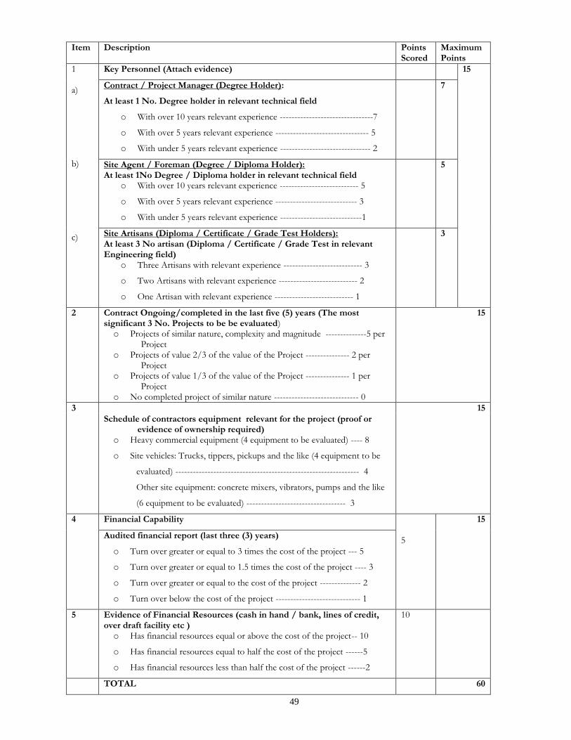
49
Item Description Points Scored
Maximum Points
1 a) b) c)
Key Personnel (Attach evidence) 15
Contract / Project Manager (Degree Holder):
At least 1 No. Degree holder in relevant technical field
o With over 10 years relevant experience --------------------------------7
o With over 5 years relevant experience -------------------------------- 5
o With under 5 years relevant experience ------------------------------- 2
7
Site Agent / Foreman (Degree / Diploma Holder): At least 1No Degree / Diploma holder in relevant technical field
o With over 10 years relevant experience --------------------------- 5
o With over 5 years relevant experience ---------------------------- 3
o With under 5 years relevant experience ----------------------------1
5
Site Artisans (Diploma / Certificate / Grade Test Holders): At least 3 No artisan (Diploma / Certificate / Grade Test in relevant Engineering field)
o Three Artisans with relevant experience --------------------------- 3
o Two Artisans with relevant experience --------------------------- 2
o One Artisan with relevant experience --------------------------- 1
3
2 Contract Ongoing/completed in the last five (5) years (The most significant 3 No. Projects to be be evaluated) o Projects of similar nature, complexity and magnitude --------------5 per
Project o Projects of value 2/3 of the value of the Project --------------- 2 per
Project o Projects of value 1/3 of the value of the Project --------------- 1 per
Project o No completed project of similar nature ----------------------------- 0
15
3 15
Schedule of contractors equipment relevant for the project (proof or evidence of ownership required)
o Heavy commercial equipment (4 equipment to be evaluated) ---- 8
o Site vehicles: Trucks, tippers, pickups and the like (4 equipment to be
evaluated) --------------------------------------------------------------- 4
Other site equipment: concrete mixers, vibrators, pumps and the like
(6 equipment to be evaluated) ---------------------------------- 3
4
Financial Capability 5
15
Audited financial report (last three (3) years)
o Turn over greater or equal to 3 times the cost of the project --- 5
o Turn over greater or equal to 1.5 times the cost of the project ---- 3
o Turn over greater or equal to the cost of the project -------------- 2
o Turn over below the cost of the project ----------------------------- 1
5 Evidence of Financial Resources (cash in hand / bank, lines of credit, over draft facility etc ) o Has financial resources equal or above the cost of the project-- 10
o Has financial resources equal to half the cost of the project ------5
o Has financial resources less than half the cost of the project ------2
10
TOTAL 60

50
Only bidders who score 70 % and above shall be considered for further evaluation
B: APPENDIX TO CONDITIONS OF CONTRACT THE EMPLOYER IS
Name: PROPOSED REHABILITATION WORKS TO CREATE OFFICES FOR THE
MURANG’A MUNICIPALITY
Address: P.O. BOX 52 – 10200 MURANG’A
Name of Authorised Representative: CHIEF OFFICER, MINISTRY OF HOUSING
AND URBAN DEVELOPMENT, MURANG’A COUNTY GOVERNMENT.
The Project Manager is: COUNTY QUANTITY SURVEYOR,
DEPARTMENT OF PUBLIC WORKS
Address: P.O. BOX 133 – 10200 MURANG’A.
The name (and identification number) of the Contract is:
PROPOSED REHABILITATION WORKS TO CREATE OFFICES FOR THE
MURANG’A MUNICIPALITY The Works consist of CONSTRUCTION WORKS AND ASSOCIATED ELECTRICAL, MECHANICAL, AND CIVIL WORKS The Start Date shall be AGREED WITH THE PROJECT MANAGER
The Intended Completion Date for the whole of the Works shall be
16 (SIXTEEN) WEEKS AFTER DATE OF POSSESSION
The following documents also form part of the Contract: BILLS OF QUANTITIES, CONTRACT DRAWINGS AND ANY OTHER AUTHORIZED DRAWINGS WHICH MAY BE ISSUED The Contractor shall submit a revised program for the Works within 2 days of
delivery of the Letter of Acceptance.
The Site Possession Date shall be AGREED WITH THE PROJECT MANAGER The Site is located MURANG’A COUNTY and is defined in drawings nos.
CONTRACT DRAWINGS
The Defects Liability period is 180 days.
Other Contractors, utilities etc., to be engaged by the Employer on the Site Include those for the execution of ;
1. ELECTRICAL WORKS
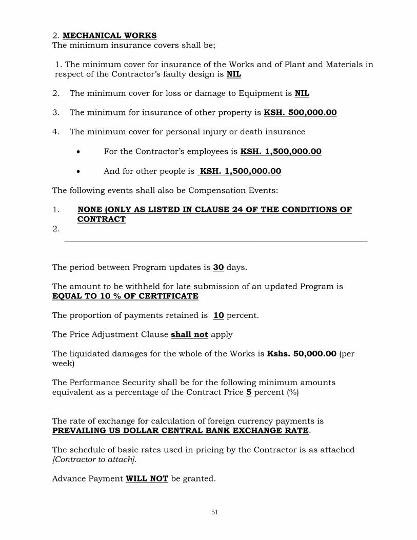
51
2. MECHANICAL WORKS The minimum insurance covers shall be;
1. The minimum cover for insurance of the Works and of Plant and Materials in
respect of the Contractor’s faulty design is NIL 2. The minimum cover for loss or damage to Equipment is NIL
3. The minimum for insurance of other property is KSH. 500,000.00
4. The minimum cover for personal injury or death insurance
For the Contractor’s employees is KSH. 1,500,000.00
And for other people is KSH. 1,500,000.00
The following events shall also be Compensation Events: 1. NONE (ONLY AS LISTED IN CLAUSE 24 OF THE CONDITIONS OF
CONTRACT 2.
__________________________________________________________________________
The period between Program updates is 30 days. The amount to be withheld for late submission of an updated Program is
EQUAL TO 10 % OF CERTIFICATE
The proportion of payments retained is 10 percent. The Price Adjustment Clause shall not apply
The liquidated damages for the whole of the Works is Kshs. 50,000.00 (per
week)
The Performance Security shall be for the following minimum amounts
equivalent as a percentage of the Contract Price 5 percent (%)
The rate of exchange for calculation of foreign currency payments is PREVAILING US DOLLAR CENTRAL BANK EXCHANGE RATE.
The schedule of basic rates used in pricing by the Contractor is as attached [Contractor to attach]. Advance Payment WILL NOT be granted.
52
SECTION V - SPECIFICATIONS
Notes for preparing Specifications
1.0 Specifications must be drafted to present a clear and
precise statement of the required standards of materials,
and workmanship for tenderers to respond realistically
and competitively to the requirements of the Employer and ensure responsiveness of tenders. The
Specifications should require that all materials, plant, and other supplies to be permanently incorporated in the Works be new, unused, of the most recent or
current models, and incorporating all recent improvements in design and materials unless provided otherwise in the Contract. Where the Contractor is
responsible for the design of any part of the permanent Works, the extent of his obligations must be stated.
2.0 Specifications from previous similar projects are useful
and may not be necessary to re-write specifications for
every Works Contract.
3.0 There are considerable advantages in standardizing
General Specifications for repetitive Works in recognized public sectors, such as highways, urban
housing, irrigation and water supply. The General Specifications should cover all classes of workmanship, materials and equipment commonly involved in
constructions, although not necessarily to be used in a particular works contract. Deletions or addenda should
then adapt the General Specifications to the particular Works.
4.0 Care must be taken in drafting Specifications to ensure they are not restrictive. In the Specifications of standards for materials, plant and workmanship,
existing Kenya Standards should be used as much as possible, otherwise recognized international standards
may also be used.
5.0 The Employer should decide whether technical solutions
to specified parts of the Works are to be permitted. Alternatives are appropriate in cases where obvious (and
potentially less costly) alternatives are possible to the technical solutions indicated in tender documents for certain elements of the Works, taking into consideration
the comparative specialized advantage of potential tenderers.
53
The Employer should provide a description of the selected parts of the Works with appropriate reference to
Drawings, Specifications, Bills of Quantities, and Design or Performance criteria, stating that the alternative solutions shall be at least structurally and functionally
equivalent to the basic design parameters and Specifications.
Such alternative solutions shall be accompanied by all information necessary for a complete evaluation by the
Employer, including drawings, design calculations, technical specifications, breakdown of prices, proposed construction methodology, and other relevant details.
Technical alternatives permitted in this manner shall be considered by the Employer each on its own merits and
independently of whether the tenderer has priced the item as described in the Employer’s design included with the tender documents.
54
SECTION VI - DRAWINGS
Note 1. A list of drawings should be inserted here (May be inspected at the
PM’s office) (As attached on page 206 - )
55
SECTION VII - BILL OF QUANTITIES
Notes for preparing Bills of Quantities
1.0 The objectives of the Bills of Quantities are;
(a) to provide sufficient information on the quantities of Works to be performed to enable tenders to be prepared efficiently and
accurately; and
(b) when a Contract has been entered into, to provide a priced Bill of Quantities for use in the periodic valuation of Works executed.
In order to attain these objectives, Works should be itemized in the Bill of Quantities in sufficient detail to distinguish between the different classes of Works, or between Works of the same nature
carried out in different locations or in other circumstances which may give rise to different considerations of cost. Consistent with
these requirements, the layout and content of the Bill of Quantities should be as simple and brief as possible.
2.0 The Bills of Quantities should be divided generally into the following sections:
(a) Preliminaries.
The preliminaries should indicate the inclusiveness of the unit prices, and should state the methods of measurement which have been adopted in the preparation of the Bill of Quantities and which
are to be used for the measurement of any part of the Works.
The number of preliminary items to be priced by the tenderer should be limited to tangible items such as site office and other temporary works, otherwise items such as security for the Works which are
primarily part of the Contractor’s obligations should be included in the Contractor’s rates.
(b) Work Items
(i) The items in the Bills of Quantities should be grouped into sections to distinguish between those parts of the Works which by nature, location, access, timing, or any other special
characteristics may give rise to different methods of construction, or phasing of the Works, or considerations of
cost. General items common to all parts of the Works may be grouped as a separate section in the Bill of Quantities.
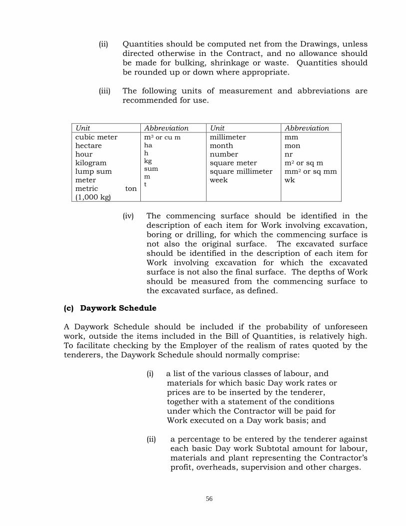
56
(ii) Quantities should be computed net from the Drawings, unless
directed otherwise in the Contract, and no allowance should be made for bulking, shrinkage or waste. Quantities should
be rounded up or down where appropriate.
(iii) The following units of measurement and abbreviations are
recommended for use.
Unit Abbreviation Unit Abbreviation
cubic meter hectare hour kilogram lump sum meter metric ton (1,000 kg)
m3 or cu m
ha
h
kg
sum
m t
millimeter month number square meter square millimeter week
mm mon nr m2 or sq m mm2 or sq mm wk
(iv) The commencing surface should be identified in the
description of each item for Work involving excavation, boring or drilling, for which the commencing surface is not also the original surface. The excavated surface
should be identified in the description of each item for Work involving excavation for which the excavated surface is not also the final surface. The depths of Work
should be measured from the commencing surface to the excavated surface, as defined.
(c) Daywork Schedule
A Daywork Schedule should be included if the probability of unforeseen
work, outside the items included in the Bill of Quantities, is relatively high. To facilitate checking by the Employer of the realism of rates quoted by the tenderers, the Daywork Schedule should normally comprise:
(i) a list of the various classes of labour, and
materials for which basic Day work rates or prices are to be inserted by the tenderer, together with a statement of the conditions
under which the Contractor will be paid for Work executed on a Day work basis; and
(ii) a percentage to be entered by the tenderer against
each basic Day work Subtotal amount for labour,
materials and plant representing the Contractor’s profit, overheads, supervision and other charges.
57
(d) Provisional Quantities and Sums (i) Provision for quantity contingencies in any particular
item or class of Work with a high expectation of
quantity overrun should be made by entering specific “Provisional Quantities” or “Provisional Items” in the Bill of Quantities, and not by increasing the quantities
for that item or class of Work beyond those of the Work normally expected to be required. To the extent not
covered above, a general provision for physical contingencies (quantity overruns) should be made by including a “Provisional Sum” in the Summary of the
Bill of Quantities. Similarly, a contingency allowance for possible price increases should be provided as a
“Provisional Sum” in the Summary of the Bill of Quantities. The inclusion of such provisional sums often facilitates budgetary approval by avoiding the need
to request periodic supplementary approvals as the
future need arises.
(ii) Provisional sums to cover specialized works normally carried out by Nominated Sub Contractors should be avoided and instead Bills of Quantities of the specialised
Works should be included as a section of the main Bills of Quantities to be priced by the Main Contractor. The
Main Contractor should be required to indicate the name (s) of
the specialised firms he proposes to engage to carry out the specialized Works as his approved domestic sub-contractors. Only provisional sums to cover specialized Works by statutory
authorities should be included in the Bills of Quantities.
(e) Summary
The Summary should contain a tabulation of the
separate parts of the Bills of Quantities carried forward, with provisional sums for Daywork, for physical
(quantity) contingencies, and for price contingencies (upward price adjustment) where applicable.
58
SECTION VIII – STANDARD FORM
(i) Form of Invitation for Tenders
(ii) Form of Tender (iii) Letter of Acceptance (iv) Form of Agreement (v) Form of Tender Security (vi) Performance Bank Guarantee (vii) Bank Guarantee for Advance Payment (viii) Qualification Information (ix) Tender Questionnaire (xi) Confidential Business Questionnaire (x) Statement of Foreign Currency Requirement (xi) Details of Sub-Contractors

59
FORM OF INVITATION FOR TENDERS
_______________________[date] To: _____________________________________ [name of Contractor] _____________________________________[address] _____________________________________ _____________________________________
Dear Sirs:
Reference:______________________________________________[Contract Name] You have been prequalified to tender for the above project.
We hereby invite you and other prequalified tenderers to submit a tender for the
execution and completion of the above Contract. A complete set of tender documents may be purchased by you from ____
________________________________________________________________________ [mailing address, cable/telex/facsimile numbers]. Upon payment of a non-refundable fee of Kshs __________________________
All tenders must be accompanied by ________________number of copies of the same and a security in the form and amount specified in the tendering documents, and must be delivered to
________________________________________________________________________ [address and location] at or before _______________________(time and date). Tenders will be opened immediately thereafter, in the presence of tenderers’ representatives who choose
to attend.
Please confirm receipt of this letter immediately in writing by cable/facsimile or telex.
Yours faithfully, _____________________________________ Authorised Signature
_____________________________________ Name and Title

60
FORM OF TENDER
TO: __________________________[Name of Employer) ____________[Date] __________________________[Name of Contract] Dear Sir,
1. In accordance with the Conditions of Contract, Specifications, Drawings
and Bills of Quantities for the execution of the above named Works, we,
the undersigned offer to construct, install and complete such Works and remedy any defects therein for the sum of
Kshs._____________________________[Amount in figures]Kenya Shillings___________________________________________________________________________________________[Amount in words]
2. We undertake, if our tender is accepted, to commence the Works as
soon as is reasonably possible after the receipt of the Project Manager’s notice to commence, and to complete the whole of the Works comprised in the Contract within the time stated in the Appendix to Conditions of
Contract.
3. We agree to abide by this tender until ___________________[Insert date], and it shall remain binding upon us and may be accepted at any time before that date.
4. Unless and until a formal Agreement is prepared and executed this tender
together with your written acceptance thereof, shall constitute a binding Contract between us.
5. We understand that you are not bound to accept the lowest or any tender you may receive.
Dated this ____________________ day of _______20________________
Signature __________________in the capacity of___________________ duly authorized to sign tenders for and on behalf of
_____________________________________________[Name of Contractor] of___________________________________________[Address of Contractor] Witness; Name______________________________________
Address_____________________________________
Signature___________________________________ Date_______________________________________
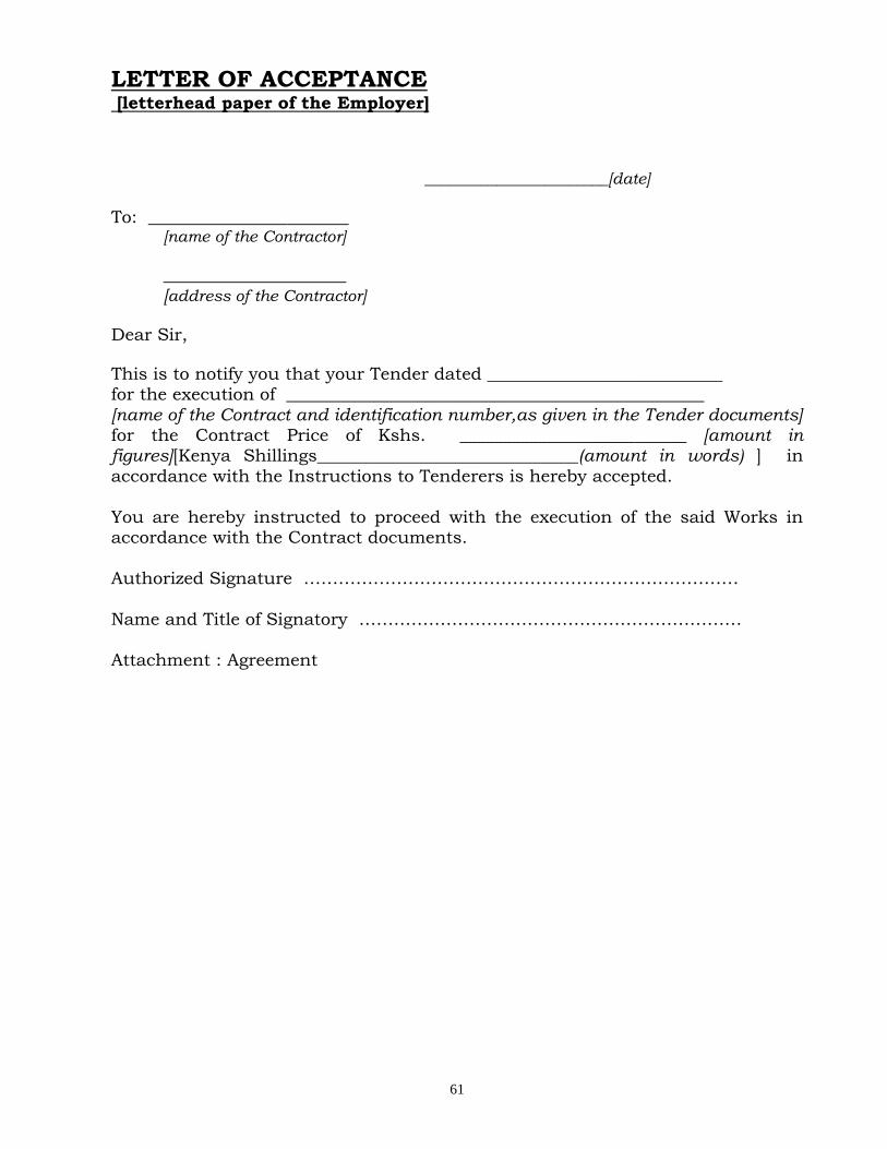
61
LETTER OF ACCEPTANCE [letterhead paper of the Employer] _______________________[date]
To: _______________________ [name of the Contractor]
_____________________
[address of the Contractor]
Dear Sir,
This is to notify you that your Tender dated ___________________________ for the execution of ________________________________________________
[name of the Contract and identification number,as given in the Tender documents] for the Contract Price of Kshs. __________________________ [amount in figures][Kenya Shillings______________________________(amount in words) ] in
accordance with the Instructions to Tenderers is hereby accepted.
You are hereby instructed to proceed with the execution of the said Works in accordance with the Contract documents.
Authorized Signature …………………………………………………………………
Name and Title of Signatory ………………………………………………………… Attachment : Agreement

62
FORM OF AGREEMENT
THIS AGREEMENT, made the _________________ day of ________ 20 ______ between________________________________________________of[or whose registered
office is situated at]__________________________________________ (hereinafter called “the Employer”) of the one part AND ________________________________________________________of[or whose registered
office is situated at]_________________________________________ (hereinafter called “the Contractor”) of the other part.
WHEREAS THE Employer is desirous that the Contractor executes ________________________________________________________________________
(name and identification number of Contract ) (hereinafter called “the Works”) located at______________________________[Place/location of the Works]and the
Employer has accepted the tender submitted by the Contractor for the execution and completion of such Works and the remedying of any defects therein for the
Contract Price of Kshs___________________________[Amount in figures],Kenya Shillings_____________________________________________[Amount in words].
NOW THIS AGREEMENT WITNESSETH as follows:
1. In this Agreement, words and expressions shall have the same meanings as are respectively assigned to them in the Conditions of Contract hereinafter referred to.
2. The following documents shall be deemed to form and shall be read and
construed as part of this Agreement i.e.
(i) Letter of Acceptance
(ii) Form of Tender
(iii) Conditions of Contract Part I
(iv) Conditions of Contract Part II and Appendix to Conditions of Contract
(v) Specifications
(vi) Drawings
(vii) Priced Bills of Quantities
3. In consideration of the payments to be made by the Employer to the Contractor as hereinafter mentioned, the Contractor hereby
covenants with the Employer to execute and complete the Works and remedy any defects therein in conformity in all respects with the
provisions of the Contract.
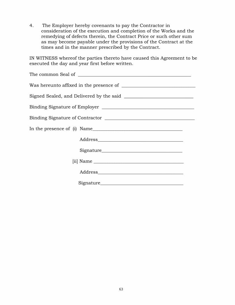
63
4. The Employer hereby covenants to pay the Contractor in
consideration of the execution and completion of the Works and the remedying of defects therein, the Contract Price or such other sum
as may become payable under the provisions of the Contract at the times and in the manner prescribed by the Contract.
IN WITNESS whereof the parties thereto have caused this Agreement to be executed the day and year first before written.
The common Seal of _________________________________________________
Was hereunto affixed in the presence of ________________________________ Signed Sealed, and Delivered by the said ______________________________
Binding Signature of Employer ________________________________________
Binding Signature of Contractor _______________________________________
In the presence of (i) Name_______________________________________ Address_____________________________________
Signature___________________________________
[ii] Name _______________________________________
Address_____________________________________ Signature____________________________________
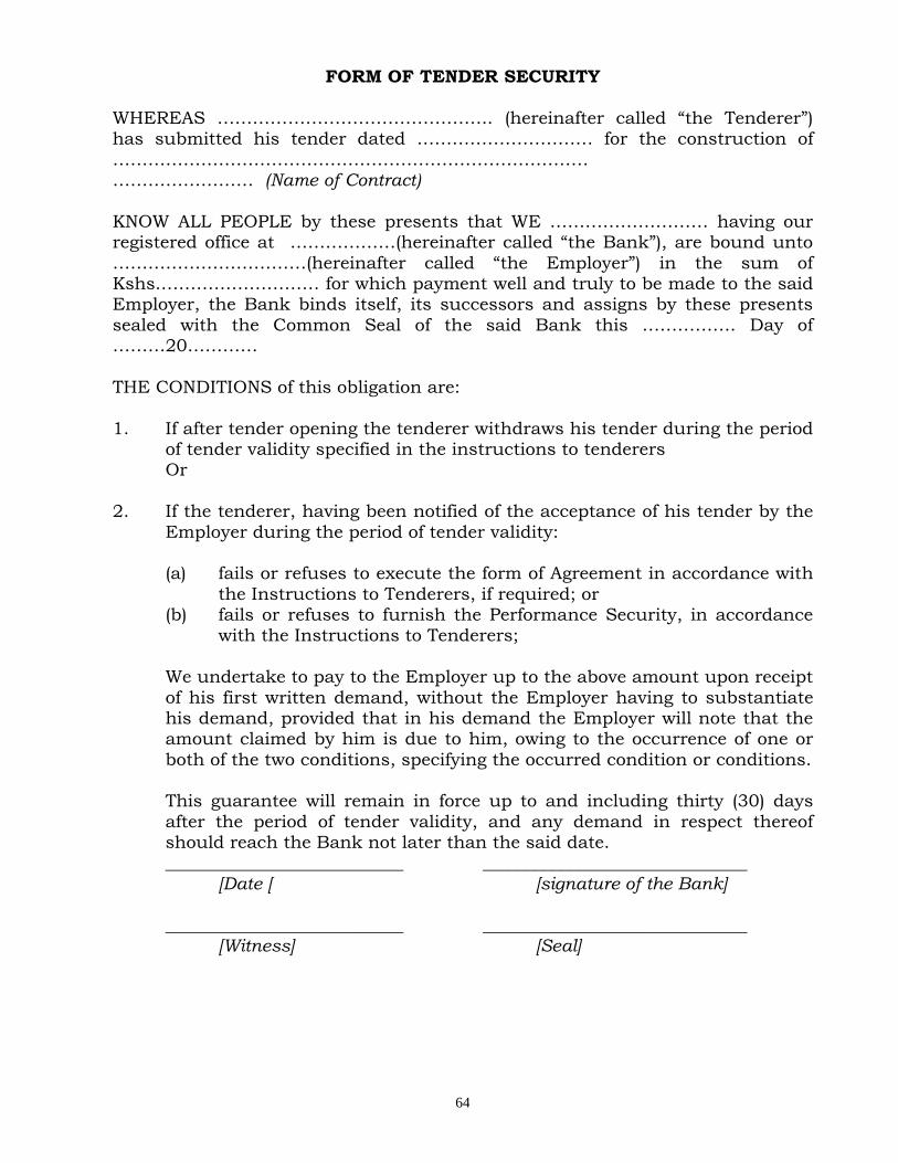
64
FORM OF TENDER SECURITY
WHEREAS ……………………………………….. (hereinafter called “the Tenderer”) has submitted his tender dated ………………………… for the construction of
……………………………………………………………………… …………………… (Name of Contract)
KNOW ALL PEOPLE by these presents that WE ……………………… having our registered office at ………………(hereinafter called “the Bank”), are bound unto
……………………………(hereinafter called “the Employer”) in the sum of Kshs.……………………… for which payment well and truly to be made to the said Employer, the Bank binds itself, its successors and assigns by these presents
sealed with the Common Seal of the said Bank this ……………. Day of ………20…………
THE CONDITIONS of this obligation are:
1. If after tender opening the tenderer withdraws his tender during the period of tender validity specified in the instructions to tenderers Or
2. If the tenderer, having been notified of the acceptance of his tender by the
Employer during the period of tender validity:
(a) fails or refuses to execute the form of Agreement in accordance with
the Instructions to Tenderers, if required; or (b) fails or refuses to furnish the Performance Security, in accordance
with the Instructions to Tenderers;
We undertake to pay to the Employer up to the above amount upon receipt
of his first written demand, without the Employer having to substantiate his demand, provided that in his demand the Employer will note that the amount claimed by him is due to him, owing to the occurrence of one or
both of the two conditions, specifying the occurred condition or conditions. This guarantee will remain in force up to and including thirty (30) days
after the period of tender validity, and any demand in respect thereof should reach the Bank not later than the said date.
___________________________ ______________________________ [Date [ [signature of the Bank] ___________________________ ______________________________ [Witness] [Seal]
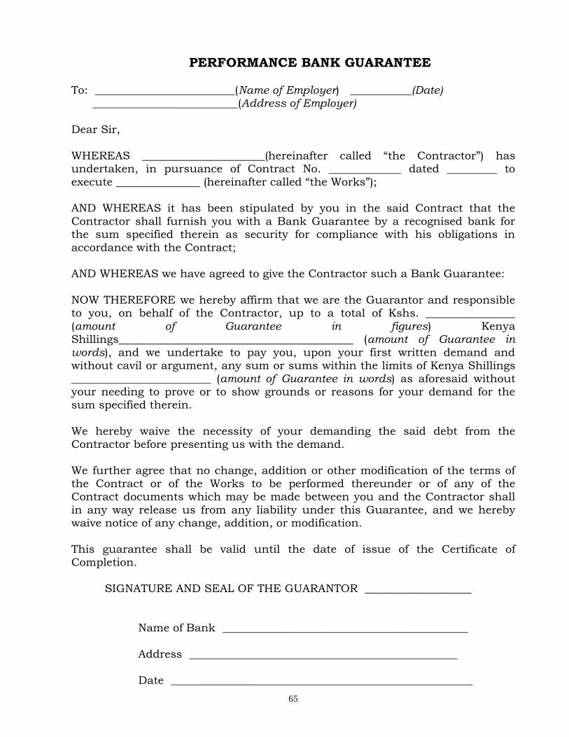
65
PERFORMANCE BANK GUARANTEE
To: _________________________(Name of Employer) ___________(Date) __________________________(Address of Employer) Dear Sir,
WHEREAS ______________________(hereinafter called “the Contractor”) has undertaken, in pursuance of Contract No. _____________ dated _________ to
execute _______________ (hereinafter called “the Works”); AND WHEREAS it has been stipulated by you in the said Contract that the
Contractor shall furnish you with a Bank Guarantee by a recognised bank for the sum specified therein as security for compliance with his obligations in
accordance with the Contract; AND WHEREAS we have agreed to give the Contractor such a Bank Guarantee:
NOW THEREFORE we hereby affirm that we are the Guarantor and responsible to you, on behalf of the Contractor, up to a total of Kshs. ________________
(amount of Guarantee in figures) Kenya Shillings__________________________________________ (amount of Guarantee in words), and we undertake to pay you, upon your first written demand and without cavil or argument, any sum or sums within the limits of Kenya Shillings
_________________________ (amount of Guarantee in words) as aforesaid without your needing to prove or to show grounds or reasons for your demand for the sum specified therein.
We hereby waive the necessity of your demanding the said debt from the
Contractor before presenting us with the demand. We further agree that no change, addition or other modification of the terms of
the Contract or of the Works to be performed thereunder or of any of the Contract documents which may be made between you and the Contractor shall
in any way release us from any liability under this Guarantee, and we hereby waive notice of any change, addition, or modification.
This guarantee shall be valid until the date of issue of the Certificate of Completion.
SIGNATURE AND SEAL OF THE GUARANTOR ___________________
Name of Bank ____________________________________________
Address ________________________________________________
Date ______________________________________________________
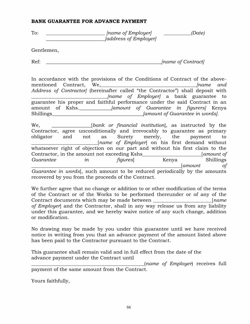
66
BANK GUARANTEE FOR ADVANCE PAYMENT
To: ________________________ [name of Employer] ___________(Date) ________________________[address of Employer] Gentlemen,
Ref: _______________________________________________[name of Contract] In accordance with the provisions of the Conditions of Contract of the above-mentioned Contract, We,_______________________________________[name and Address of Contractor] (hereinafter called “the Contractor”) shall deposit with _______________________________[name of Employer] a bank guarantee to
guarantee his proper and faithful performance under the said Contract in an amount of Kshs._____________[amount of Guarantee in figurers] Kenya
Shillings_____________________________________[amount of Guarantee in words].
We, ________________[bank or financial institution], as instructed by the Contractor, agree unconditionally and irrevocably to guarantee as primary obligator and not as Surety merely, the payment to
___________________________[name of Employer] on his first demand without whatsoever right of objection on our part and without his first claim to the
Contractor, in the amount not exceeding Kshs________________________[amount of Guarantee in figures] Kenya Shillings
_____________________________________________________________[amount of Guarantee in words], such amount to be reduced periodically by the amounts
recovered by you from the proceeds of the Contract. We further agree that no change or addition to or other modification of the terms
of the Contract or of the Works to be performed thereunder or of any of the Contract documents which may be made between ________________________[name of Employer] and the Contractor, shall in any way release us from any liability under this guarantee, and we hereby waive notice of any such change, addition or modification.
No drawing may be made by you under this guarantee until we have received
notice in writing from you that an advance payment of the amount listed above has been paid to the Contractor pursuant to the Contract.
This guarantee shall remain valid and in full effect from the date of the advance payment under the Contract until
______________________________________________(name of Employer) receives full payment of the same amount from the Contract.
Yours faithfully,

67
Signature and Seal __________________________________________________
Name of the Bank or financial institution ______________________________
Address ______________________________________________________________ Date _________________________________________________________________
Witness: Name: ____________________________________________________
Address: __________________________________________________
Signature: ________________________________________________ Date: _____________________________________________________

68
QUALIFICATION INFORMATION 1. Individual Tenderers or Individual Members of Joint Ventures
1.1 Constitution or legal status of tenderer (attach copy or Incorporation Certificate); Place of registration: ____________________________
Principal place of business _____________________________
Power of attorney of signatory of tender ____________________
1.2 Total annual volume of construction work performed in the last five years
Year Volume
Currency Value
1.3 Work performed as Main Contractor on works of a similar nature
and volume over the last five years. Also list details of work under way or committed, including expected completion date.
Project name Name of client Type of work Value of and contact performed and Contract
person year of completion
_________ ___________ __________ ________ _________ ___________ __________ ________
________ __________ __________ _______
1.4 Major items of Contractor’s Equipment proposed for carrying out the
Works. List all information requested below.
Item of Equipment
Description, Make and age (years)
Condition(new, good, poor) and number
available
Owned, leased (from whom?), or to be
purchased (from whom?)
__________________
_________(etc.)
________________________
____________
______________________
___________
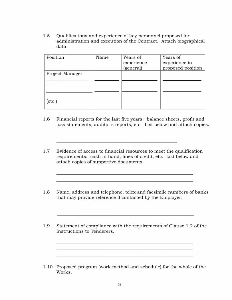
69
1.5 Qualifications and experience of key personnel proposed for
administration and execution of the Contract. Attach biographical data.
Position Name Years of experience
(general)
Years of experience in
proposed position
Project Manager
__________________ ___________________
(etc.)
1.6 Financial reports for the last five years: balance sheets, profit and
loss statements, auditor’s reports, etc. List below and attach copies.
________________________________________________________________________________________________________________________
1.7 Evidence of access to financial resources to meet the qualification requirements: cash in hand, lines of credit, etc. List below and attach copies of supportive documents.
____________________________________________________________ ____________________________________________________________
_____________________________________________
1.8 Name, address and telephone, telex and facsimile numbers of banks that may provide reference if contacted by the Employer.
__________________________________________________________________ ____________________________________________________________
1.9 Statement of compliance with the requirements of Clause 1.2 of the
Instructions to Tenderers.
____________________________________________________________
____________________________________________________________
_____________________________________________
1.10 Proposed program (work method and schedule) for the whole of the Works.
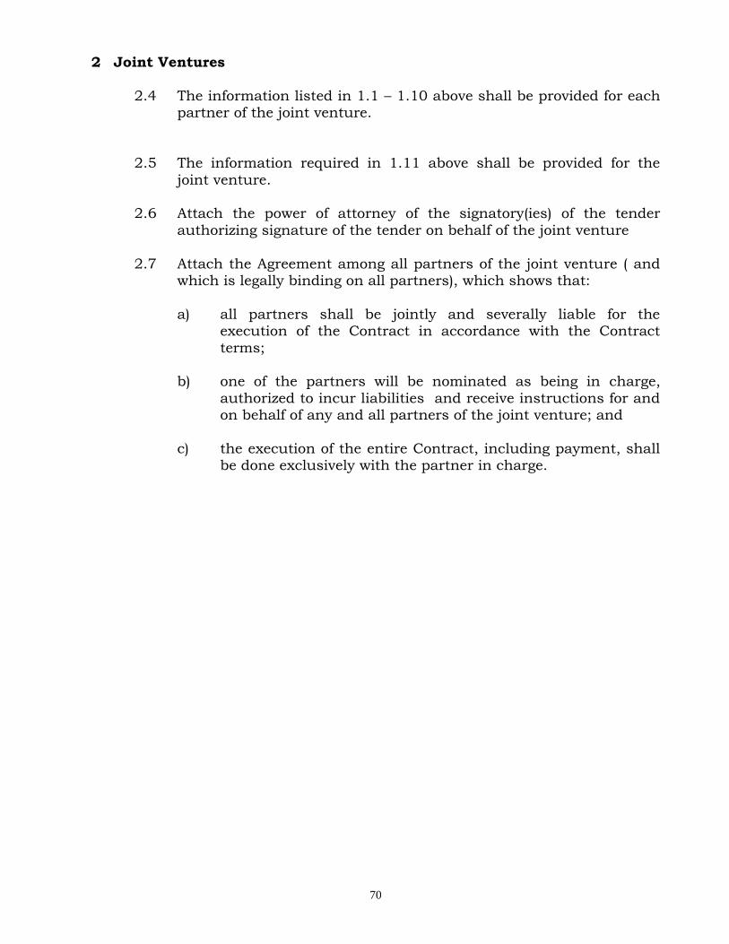
70
2 Joint Ventures
2.4 The information listed in 1.1 – 1.10 above shall be provided for each partner of the joint venture.
2.5 The information required in 1.11 above shall be provided for the
joint venture.
2.6 Attach the power of attorney of the signatory(ies) of the tender
authorizing signature of the tender on behalf of the joint venture
2.7 Attach the Agreement among all partners of the joint venture ( and which is legally binding on all partners), which shows that:
a) all partners shall be jointly and severally liable for the execution of the Contract in accordance with the Contract
terms;
b) one of the partners will be nominated as being in charge,
authorized to incur liabilities and receive instructions for and on behalf of any and all partners of the joint venture; and
c) the execution of the entire Contract, including payment, shall be done exclusively with the partner in charge.
71
TENDER QUESTIONNAIRE
Please fill in block letters.
1. Full names of tenderer
………………………………………………………………………………………
2. Full address of tenderer to which tender correspondence is to be sent
(unless an agent has been appointed below)
………………………………………………………………………………………
3. Telephone number (s) of tenderer
………………………………………………………………………………………
4. Telex address of tenderer
………………………………………………………………………………………
5. Name of tenderer’s representative to be contacted on matters of the tender
during the tender period
………………………………………………………………………………………
6. Details of tenderer’s nominated agent (if any) to receive tender notices.
This is essential if the tenderer does not have his registered address in
Kenya (name, address, telephone, telex)
………………………………………………………………………………………
………………………………………………………………………………………
_______________________ Signature of Tenderer
Make copy and deliver to:_____________________(Name of Employer)

72
CONFIDENTIAL BUSINESS QUESTIONNAIRE
You are requested to give the particulars indicated in Part 1 and either Part 2 (a), 2 (b) or 2 (c) and 2 (d) whichever applies to your type of business.
You are advised that it is a serious offence to give false information on this Form.
Part 1 – General Business Name ……………………………………………………………………… Location of business premises; Country/Town……………………….
Plot No……………………………………… Street/Road …………………………
Postal Address……………………………… Tel No………………………………..
Nature of Business………………………………………………………………….. Current Trade Licence No…………………… Expiring date…………………
Maximum value of business which you can handle at any time: K.
pound……………………….. Name of your bankers………………………………………………………………
Branch…………………………………………………………………………………
Part 2 (a) – Sole Proprietor Your name in full…………………………………… Age………………………… Nationality………………………………… Country of Origin…………………
*Citizenship details …………………………………………………………………
Part 2 (b) – Partnership Give details of partners as follows: Name in full Nationality Citizenship Details Shares 1…………………………………………………………………………………… 2……………………………………………………………………………………
3……………………………………………………………………………………
73
Part 2(c) – Registered Company:
Private or public……………………………………………………………
State the nominal and issued capital of the Company- Nominal Kshs…………………………………………………………………
Issued Kshs……………………………………………………………………
Give details of all directors as follows:
Name in full . Nationality. Citizenship Details*. Shares.
1. ………………………………………………………………………………………
2. ………………………………………………………………………………………
3. ………………………………………………………………………………………
4.
……………………………………………………………………………………… Part 2(d) – Interest in the Firm:
Is there any person / persons in …………… ………(Name of Employer) who
has interest in this firm? Yes/No………………………(Delete as necessary)
I certify that the information given above is correct.
……………………… ……………………… ………………… (Title) (Signature) (Date)
Attach proof of citizenship
74
STATEMENT OF FOREIGN CURRENCY REQUIREMENTS
(See Clause 23] of the Conditions of Contract)
In the event of our Tender for the execution of____________________ __________________________(name of Contract) being accepted, we would require in accordance with Clause 21 of the Conditions of Contract, which
is attached hereto, the following percentage:
(Figures)………………………… (Words)………………………………… of the Contract Sum, (Less Fluctuations) to be paid in foreign currency.
Currency in which foreign exchange element is required:
………………………………………………………………………………………
Date: The ………… Day of …………….. 20…………….
Enter 0% (zero percent) if no payment will be made in foreign currency.
Maximum foreign currency requirement shall be _____________(percent) of the Contract Sum, less Fluctuations.
_____________________
(Signature of Tenderer)
75
DETAILS OF SUB-CONTRACTORS
If the Tenderer wishes to sublet any portions of the Works under any heading, he must give below details of the sub-contractors he intends to
employ for each portion. Failure to comply with this requirement may invalidate the tender.
(1) Portion of Works to be sublet: ………………………………
[i) Full name of Sub-contractor and address of head office: ………………………………
………………………………
(ii) Sub-contractor’s experience of similar works carried out
in the last 3 years with Contract value: ………………………………
……………………………… ………………………………
(2) Portion of Works to sublet: ………………………………
(i) Full name of sub-contractor and address of head office: ………………………………
………………………………
………………………………
(ii) Sub-contractor’s experience of similar works carried out in the last 3 years with
contract value: ……………………………
……………………………
____________________ _______________________ [Signature of Tenderer) Date

76
LETTER OF NOTIFICATION OF AWARD
Address of Procuring Entity
_____________________ _____________________ To:
RE: Tender No.
Tender Name
This is to notify that the contract/s stated below under the above mentioned tender have been awarded to you.
1. Please acknowledge receipt of this letter of notification signifying your acceptance.
2. The contract/contracts shall be signed by the parties within 30 days of the
date of this letter but not earlier than 14 days from the date of the letter.
3. You may contact the officer(s) whose particulars appear below on the
subject matter of this letter of notification of award. (FULL PARTICULARS)
SIGNED FOR ACCOUNTING OFFICER

77
SPECIFICATIONS AND PRICING NOTES
78
SPECIFICATIONS AND PRICING NOTES BILL NO. 1 SPECIFICATIONS AND PRICING NOTES The contractor should read carefully the following specification for workmanship prepared in accordance with standard specifications for building works 1976 Edition prepared by the Ministry of Public Works
GENERAL ITEMS
Materials Generally A.1 All materials used on the works shall be new and of the qualities and kinds specified herein and
equal to approved samples. Deliveries shall be made sufficiently in advance to enable samples to be taken and tested if required. No materials shall be used until approved and all materials which are not approved or which are damaged, contaminated or have deteriorated in any way or do not comply in any way with the requirements of this specification shall be rejected and shall be immediately removed from the site at the Contractors expense.
A.2 Material for which there is a Kenya Bureau of Standard specification
All materials used in the works for which a Kenya Bureau of Standards Specification has been published shall conform with the latest edition thereof in every way. The Architect reserves the right to demand that the Contractor shall obtain at his own expense a certificate in respect of any materials to state that is in accordance with the Kenya Bureau of Standard specification.
A.3 Materials for which there is no Kenya Bureau of Standards specification
All materials used in the works for which no Kenya Bureau of Standards specifications has been published shall conform with the British Standards Specification for such materials. If there are no published standards as specified for any materials, the quality of such materials shall be generally of a standard equal to those for which there is a Kenya Bureau of Standards or British Standard specification.
79
EXCAVATION AND EARTHWORK
B.1 Site Clearance
Site Clearance shall include the cutting down of all trees, stumps, bushes, vegetation and rubbish, burning the debris arising in approved locations and carting remaining material to a tip provided by the Contractor.
B.2 Nature of the Soil The Contractor is advised to visit the site and ascertain the nature of the ground to be excavated and the shall price accordingly and no claim will be allowed for want of knowledge in this respect. Rates for excavation shall include for excavation in soil, earth, black cotton, sandy soil, murram, tuff, soft rock, boulders or whatever other subsoil is encountered except hard rock as defined below..
B.3 Foundation Excavations a) The foundation trenches and column bases shall be excavated to the widths and depths of the
concrete foundations shown on the drawings or to such widths and depths as the Engineer may instruct after examination of the excavations. Quantities of all excavations shall be measured and valued by the Quantity Surveyor and any difference between such measurements and the measurements herein given shall be dealt with as a variation to the Contractor. If however, the Contractor excavates to any greater depths than shown in the drawings or as instructed by the Engineer, then he shall at his own expense fill in such extra depth of excavation with concrete as specified for the foundations to the satisfaction of the Engineer. The Contractor shall not be paid for the cost of any excavation executed deeper or wider than shown on the drawings or instructed by the Engineer nor the cost of back filling such excavation or disposing of surplus.
B.4 Surplus Soil Disposal
Excavated material not required for subsequent refilling shall be removed to areas off site which shall be approved by the Architect.
B.5 Top Soil for Spreading
Where required in the Bills of Quantities, top soil required for subsequent spreading over finished work shall be especially selected and shall be dumped in special heaps as indicated by the Architect. Such top soil shall be reasonably free from vegetation to the satisfaction of the Architect and shall be compacted as little as possible in the heaps.

80
B.6 Filling under Surface Beds in Buildings i) Murram filling
Murram for filling as base course shall be from an approved source and of the highest quality. It shall be laid in layers not less than 150mm thick and not greater than 230 mm thick prior to compaction. Water will be applied to O.M.O. and each layer will be thoroughly compacted by at least 8 passes of a 10 tonne smooth wheeled roller or a 2 tonne vibrating roller until all movement ceases and 100% C.B.R. is obtained.
ii) Hardcore filling Hardcore filling shall be crushed rock, broken concrete or other approved hard granular materials broken to pass not greater than a 150mm ring or to be 75% of the finished thickness of the layers being compacted whichever is the less and graded so that it can be easily and thoroughly compacted by rolling. The filling is to be laid in layers each of a consolidated thickness not exceeding 230 mm.
B.7 Anti-termite treatment
Where described the top surface of filling shall be treated with Gladiator T C Pesticides to be supplied and applied by Rentokil Ltd. P.O. Box, 44360, Nairobi or other equal and approved firm strictly in accordance with the satisfaction of the Architect. The Contractor must destroy any termite nests found within the perimeter of the building and within 20 metres from the building externally and take out and destroy queens, impregnate holes and tunnels with approved insecticide and backfill with hard material, well rammed rammed and consolidated. The specialist shall be required to issue a 10 year guarantee to the Engineer.
B.8 Polythene Sheeting
Polythene sheeting shall be produced by an approved manufacturer. Joints in sheeting shall be treble folded with a 150mm fold and taped at 300mm intervals with 50mm wide back plastic adhesive tapes. The sheeting shall not stretched but shall be laid with sufficient wrinkles to permit shrinkage up to 15%. The Contractor shall ensure that the membrane is not pierced buying laying and concreting.
B.9 Existing Services
Before commencing works, the Contractor shall at his own expense ascertain in writing from the relevant Local Authorities and all other Public bodies, companies and persons who may be affected, the position and depths of their respective ducts, cables, mains or pipes and appurtenance. He shall thereupon search for and locate such services. Active existing services shall be adequately protected from damage or relocated as directed by the Architect. Inactive services shall be removed or sealed off in accordance with the direction of the Architect.
81
B.1O Protection
The Contractor shall protect all graded and filled areas from the actions of the elements. Any settlement or washing away that occur prior to acceptance of the works shall be repaired and grades re-established to the required elevations and slopes.
CONCRETE WORK C.1 Codes of Practice
All workmanship, materials, tests and performances in connection with reinforced concrete shall be in conformity with the latest edition of the British Standard for concrete works 9B.S. B 10 parts 1 & 2, B.S 8004, BS. 8007) and any other approved Local and International Standards. Where inconsistency exists between these preambles and these Standards, the Contractor shall notify the Engineer in good time for his Clarification as to which of the two implications on the Contract.
C.2 Supervision
A competent person approved by the Engineer shall be employed by the Contractor whose duty will be to supervise all stages in the preparation and placing of the concrete. All cubes shall be made and site tests carried out under his direct supervision on Consultation with the Engineer.
C.3 Cement Cement unless otherwise specified shall be ordinary Portland Cement of a brand and source approved by the Engineer and shall comply With the requirements of K.S.02-21. A manufacturers certificate of test in accordance with K.S.0221 shall be supplied for each consignment delivered to the site.
C.4 Aggregate Aggregates shall conform with the requirement K.S.02-95 and all the proposed sources, types and grading test results of all aggregates are to be approved in all respects by the Engineer before work commences. If in the opinion of the Engineer the aggregate meets with the above requirements but is dirty or adulterated in any manner, it shall be screened and/or washed with clean water at the Contractors expense. Aggregate shall be delivered to the Site in their prescribed sizes or gradings and shall be stock-pilled on paved areas to boarded platforms in separate units to avoid intermixing. On no account shall premixed cores aggregates be brought to the patching plant. On no account shall aggregates be stock-piled on the ground.
82
C.5 Water
The water used for mixing concrete shall be from an approved source, clean, fresh and free from harmful matter and comply with the requirements of B.S.3148.
C.6 Quality Control at Works Stage
Once the concrete mix is accepted from preliminary to works stage, the principal basis of control shall be analysis of the cube test results at 28 days.
C.7 Cement
The Quantity of cement shall be measured by weight. Where delivered in bags, each batch of concrete is to contain one or more bags of cement in accordance with the proportions specified. For non-structural concrete, volume batching may be used as indicated below: Class of Concrete 15 10 Nominal mix by volume 1:3:6 1:4:8 Cubic metres of fine aggregate Per 50 kg. bag of cement 0.12 0.16 Cubic metres of coarse aggregate Per 50kg bag of cement 0.24 0.32 Max. size of coarse aggregate 40mm* 40mm* *or 20mm for blinding concrete where described. Where batching is by volume, approved gauge boxes of such a size as will give the correct proportions shall be used, and full account shall be taken of bulking due to high moisture contest.
C.8 Construction Joints
Construction joints shall be permitted only at the positions predetermined on the drawings or as instructed on the site by the Engineer. In general they shall be located at points of minimum shear, viz, vertical at, or near micspans of slabs, ribs and deems.
C.9 Faulty Concrete
Any concrete which fails to comply with these Preambles, or which shows signs or setting before it is placed small be taken Out and removed from the bite, where concrete is round to be defective after set the concrete shall be cut out and replaced in accordance with the Engineers instructions. On no account shall any faulty, honeycombed or otherwise defective concrete be required or patched until the Engineer has made an inspection and issued instructions for the repair.
83
C.10 Steel reinforcement
The steel reinforcement shall comply with the latest requirements of the following British Standards:- Hot rolled MS for the Reinforcement of concrete KS 02-22 Hot rolled MS for the Reinforcement of concrete KS 4449 Cold worked H .Y. steel for the Reinforcement of concrete BS 4461 Hard drawn steel wire BS 4482
C.11 Fabric Reinforcement Fabric reinforcement shall be electrically cross-welded steel wire mesh reinforcement to BS. 1483 and of the size and weight specified and made of wire to B.S. 4482.
C.12 Fixing Steel Reinforcement
Reinforcement shall be accurately bent to the shapes and dimensions shown on the Drawings and Schedules and in accordance with B.S. 4466 and B.S. 8110. Reinforcement must be cut and bent cold and no welded joints will be permitted unless to detailed or directed by the Engineer.
C.13 Formwork
The method and system of formwork which the Contractor proposed to use shall be approved by the Engineer before construction commences. Formwork shall be substantially and rigidly constructed of timber, steel, plastic, pre-cast concrete or other approved material. All timber formwork shall be good, sound, clean, sawn, well-seasoned timber free from warps and loose knots and scantlings sufficiently strong for their purpose.
84
WALLING
MATERIALS D.1 Cement
Cement Used for making mortar shall be as described in concrete work.
D.2 Lime
The lime for making mortar shall be obtained from an approved source and shall comply with BS 890 class A for non-hydraulic lime. The lime to be run to putty in an approved lined pit or container. The water to be first run into the pit or container and the lime to be added until it is completely submerged, stirred vigorously until all lumps are disintegrated and shall be kept constantly covered with water and regularly stirred for at least four weeks. The resulting milk-lime then to be run through a fine sieve and run into a pit or other container and kept clean and moist for not less than two weeks before being used in the works.
D.3 Sand
Sand used for making mortar shall be clean, well graded siliceous sand of good sharp hard quality equal to samples which shall be deposited with and approved by the Architect. It shall be free from lumps of stone, earth, earth, loam, dust, salt, organic matter and other deleterious substances, passed through a fine sieve and washed with clean water if so directed by the Architect.
D.4 Water
Shall be as described in Concrete work. D.5 Stone
All stone shall comply with the requirements of CP 121.202 for masonry and rubble walls respectively
except where amended or extended by the following clauses.
D.6 Reinforced Walls
Steel reinforcing bars in walls shall be carefully placed and spacers used to ensure that a minimum of 20 mm cover is given to the reinforcement unless otherwise specified. Horizontal reinforcement in mortar joints shall be laid such that the reinforcement is not in contact with the blocks or stone.
85
D.7 Wall Ties
Wall ties shall be provided to connect walls to steel or concrete columns and beams to connect two unbounded leaves of wall. Wall ties shall be provided at 450mm centres both vertically and 900mm centres horizontally and shall be staggered when used to connect two leaves of unbounded wall. Wall ties shall be embedded into each material by a minimum of 50mm
D.8 Fair Face
All concrete and hollow blockwork described as finished with a fair face is to be built to a true and even face with the joints finished as specified hereinafter.
D.9 Pointing
Pointing of walls shall be prepared for pointing by raking out all loose or friable material to a minimum of 15 mm to form a square recess. The joints shall then be wetted and new mortar shall be forced into the joints and finished as directed.
86
GLAZING
MATERIALS E.l General
Glass used in glazing and for mirrors shall be best quality clear glass free from visible defects so that to afford uninterrupted vision or reflection as appropriate and without obvious distortion.
E.2 Standards Glass for glazing and mirrors shall be approved manufacture and is to comply with B.S. 952 in all respects free from flaws, bubbles, specks and other imperfections.
E.3 Clear sheet glass etc
The clear sheet glass shall be ordinary glazing (OG) quality.
E.4 Obscured Glass
To be of type described and as approved Architect. E.5 Putty
a) The putty for glazing to wood sashes is to be linseed oil putty all as B.S. 644. Workmanship WORKMANSHIP
E.6 General
Glazing of all types in all locations shall be carefully executed by artisans skilled in this type of work and in conformance with the recommendations of CP 152. Glazing shall be carefully fitted so that it is not subject to pressure and stresses imposed by being an oversight fit within framing.
87
METALWORK MATERIALS F.1 Generally
All material shall be the best of their respective kinds free from defects and all work to be carried out in the most workmanlike manner and strictly as directed by the Architect. The materials in all stages of transportation, handling and stacking shall be kept clean and prevented from injury by breaking, bending or distortion and weather action.
F.2 Mild Steel
Mild steel shall comply with B.S. 15. F.3 Hollow Section Tubing
Square and rectangular hollow section tubing shall be hot rolled mild steel in accordance with Grade 43C of BS 4360.
F.4 Bolts, Nuts and Washers
These shall be fabricated from materials which comply with B.S.15 and each manufactured item shall comply with the appropriate B.S.
F.5 Galvanized Sheet Steel
To be No.24 S.W.G. of approved manufacture to B.S. 2989 of quality mild steel sheets cold rolled close annealed patent flattened and hot dip galvanized.
F.6 Stainless Steel
Stainless steel tube shall be Austenic steel B.S. comparable to B.S. 1449 Type 316 S 16. F.7 Steel Grilles
Steel Grilles shall be manufactured from section confirming with B.S.990 of heavy duty sections of the metric W20 range of approved manufacture and design approved by the Architect. After manufacture and before delivery to site steel windows are to be hot galvanized by dipping in a bath of molten zinc or painted with one coat primer.
88
WORKMANSHIP F.8 Welding
All welding is to be in accordance with the requirements of B.S.1856 and 938 and the electrodes shall comply with B.S. 639.
F.9 Painting
All steel is to be wire brushed and any loose scale, dirt or grease shall be removed before any painting is commenced. One coat of red oxide primer type A to B.S. 2523 shall be applied at the shop. Any damage to the printing paint shall be made good to the Architects satisfaction.
F.1O Fixing of Steel Grilles
Fixing of metal grilles shall include for assembling and fixing, including screwing to sub-frames or cutting mortices for lugs in concrete or walling and running with cement mortar (1:4), bedding frames in similar mortar, pointing in mastic, bedding sills, transoms and mullions in mastic, making good finishings around both sides and fixing, and adjusting all fittings and frames.
89
FLOOR, WALL AND CEILING FINISHINGS
PLASTERWORK G.1 Generally
Render, both internal and external shall be cement and sand in the proportions 1:4 finished to the thickness specified. Plaster shall consist of an undercoat of 1 part cement to 6 parts sand by volume, and a finishing coat of 1 part cement to 10 parts lime putty. Each coat shall be finished to the thickness specified.
G.2 Cement
Ordinary Portland cement and shall comply with KS. 02-21. White and coloured cements shall comply with B.S. 12 and be obtained from an approved manufacturer.
G.3 Lime
Lime shall be prepared from hydrated lime complying with B.S. 890, Part 2.
G.4 Sands
Sands for cement and lime mixes shall comply with B.S. 1199, Table 1.
G.5 Water
Water shall be clean and kept free from all impurities. G.6 Mixing of materials
All materials shall be thoroughly mixed in the proportions described. No mixes of plasters, other than described shall be used.
G.7 Period between coats
Cement - lime undercoats shall be allowed to dry out thoroughly before a further coat is applied. G.8 Surfaces of beds and backings
Screeded beds for insitu finishings of floor finishings bedded in mortar, shall be left rough from the screeding board.
90
Floated beds for inflexible floor finishings bedded in mastic, shall be left with a plain untextured surface. Trowelled beds for flexible finishings shall be finished smooth and free from score marks, or depressions. Screeded backings for insitu wall finishings or wall finishings bedded in mortar shall be scratched for key. Floated backings for inflexible wall finishings fixed with adhesive shall be left with a plain surface. Trowelled backing for flexible wall finishings shall be finished smooth and free from score marks or depressions. Beds and Backings for finishings by specialists shall be to the approval of the specialist.
G.9 Preparation of surfaces
All surfaces to receive the finishings in this section shall be thoroughly cleaned. Screech to receive finishings bedded in mortar shall be well wetted before laying is commenced.
91
PAINTING AND DECORATING
MATERIALS H.1 Colour range
Painting and decorative schemes shall be carried out in colours selected by the Architect from the approved range of colours.
H.2 Approval of brands
The Contractor shall seek, in writing, approval from the Architect for all brands of paint he wishes to use.
H.3 Quality of Products
Where a type of paint is produced by the Manufacturer in more than one quality, only paints and materials of the first or best quality shall be used in the works. The container label shall indicate clearly the quality of the paint being used. Where it is not evident that the first or best quality of paint is being used, the Architect will order the removal of such materials from the site and rectification of any work executed with those materials, all at the Contractors expense.
H.5 Same makers materials used for coating
While materials for the work may be obtained from several makers, undercoats and finishing coats for a particular surface must be obtained from the same maker, (i.e. one makers undercoat).
H.8 Remedying defects due to defective materials
All materials, which in the opinion of the Architect are unsatisfactory shall be immediately removed from the site and any work executed with such defective materials shall be made good by the Contractor expense, to the satisfaction of the Architect.
H.15 Emulsion paint
Emulsion paint (interior and/or exterior), shall have a P.V.A. base and shall be of an approved band. The first coat shall be thinned in accordance with the manufactures instructions. Where described as applied externally, the paint shall incorporate an approved fungicide to prevent fungus growth.
H.16 Black bituminous paint Black bituminous paint shall comply with B.S. 3416, Type I for general use, Type II for drinking water tanks.
92
H.20 Primer for iron and steelwork
Primer for iron and steelwork shall be: a) Lead based priming paint complying with B.S. 2523, Type B. a) Calcium plumbate priming paint complying with B.S. 3698, Type A.
H.25 Primer for woodwork
Primer for internal woodwork, other than the internal surfaces of external doors, windows and their frames and backs of frames and linings, etc. in contact with masonry, concrete or plaster, shall be leadless white or light grey priming paint not darker than 9-093 of B.S. 4800 which shall be compatible with the subsequent coats and obtained from the same maker.
H.26 Oil paints
Hard gloss, semi-gloss matt and flat oil paints, and respective undercoats, shall be approved quality, as appropriate.
H.27 Polyurethane lacquer
Polyurethane lacquer shall be an approved single pack or two pack lacquer as described of interior or exterior quality, as appropriate.
H.31 Plaster, rendering, concrete blockwork and brickwork
All plaster or mortar splashes, etc shall be removed from plaster rendering, concrete, block, work and brickwork by careful scraping; all holes, cracks, etc., shall be stopped and the whole of the surfaces shall be brushed down to remove dust and loose materials. In addition, all traces of mould oil shall be removed from concrete surfaces by scrubbing with water and detergent and rinsing with clean water to remove all detergent.
H.35 Iron and steel
Before fixing, all rust and scale shall be removed from iron and steel surfaces by wire-brushing, scraping, hammering, flame cleaning etc.
H.37 Hardwood
All dirt and grease shall be removed from hardwood surfaces. After priming, all nail holes and other imperfections shall be stopped.
93
H.38 Fibreboard
All dirt shall be brushed off from fibreboard surfaces. After priming all nail holes and other imperfections shall be stopped.
H.39 Plywood
Surfaces of plywood to be painted shall be filled as required with a plaster based filler for internal work, and a filler as described in stopping here before for external work, and then rubbed down and all dust and loose materials brushed off.
H.40 Woodwork to be painted
Before fixing woodwork, all surfaces which will be visible after fixing shall be rubbed down and all knots and resin pockets shall be scorched back and coated with knotting. After priming and fixing, all nail holes and other imperfections shall be stopped and the whole surface shall be rubbed down and all dust brushed off.
H.41 Woodwork to receive clear finish
All holes and other imperfections in surfaces to receive a clear finish shall be stopped and the whole surface shall be rubbed down to a fine satin finish and all dust brushed off.
Workmanship
H.42 Standard of workmanship
Prior to the commencement of internal or external decoration, areas not exceeding 50 square metres in total area, and designated by the Architect, shall be completely decorated, and after approval shall be used as a standard for the whole of the works. Any additional cost involved in carrying out such decoration in advance of the general work shall be deemed be included in the Contract Sum. Such decorated surfaces shall be made good and touched up as necessary prior to the handling over of the works.
94
H.43 Stirring of materials
The contents of all cans and containers of all materials must be properly and thoroughly stirred before and during use and shall be suitably strained as and when necessary.
H.44 Manufacturers instructions
All materials shall be used strictly in accordance with instructions issued by the manufacturers concerned. The addition of thinners, driers or other materials will only be permitted when specially required by the maker and the procedure approved by the Architect.
H.45. Brush work
Unless otherwise described, all coatings shall be applied by brush. Written permission must be obtained from the Architect for the application of coatings by spray or roller where not so described, and if permission is granted, such application shall not result in extra cost to the Employer.

95
REPUBLIC OF KENYA
MINISTRY OF PUBLIC WORKS
GENERAL SPECIFICATIONS
FOR
MECHANICAL PLUMBING AND DRAINAGE
WORKS,
FIRE FIGHTING EQUIPMENTS,
SOLAR WATER HEATING
INSTALLATIONS
+
ISSUED BY:
CHIEF ELECTRICAL & MECHANICAL ENGINEER (BS) MINISTRY OF PUBLIC WORKS P.O. BOX 41191,
NAIROBI.
96
CONTENT PAGE
CLAUSE DESCRIPTION PAGE
1.00 Part 1: General mechanical specification
1.01 Introduction 96
1.02 Quality of materials 97
1.03 Regulations and standards 98
1.04 Electrical requirements 98
1.05 Transport and storage 98
1.06 Site supervision 98
1.07 Installation 99
1.08 Testing 99
1.09 Colour coding 100
1.10 Welding 101
1.11 Welding PP-R pipes 101
1.12 Welding Qualifications 102
2.00 Part2: Particular specifications for plumbing and drainage
2.01 Introduction 103
2.02 Materials and standards 103
2.2.1 Pipework and Fittings 103
2.2.2 Valves 105
2.2.3 Waste Fitment Traps 106
2.2.4 Pipe Supports 106
2.2.5 Sanitary Appliances 108
2.2.6 Pipe Sleeves 108
2.03 Installation 108
2.3.1 General 108
2.3.2 Above Ground Installation 108
2.04 Testing Inspection 110
2.4.1 Site Tests – Pipework Systems 110
2.4.2 Site Test – Performance 110
2.05 Sterilization of Hot and Cold Water System 111
3.00 Part3: Particular specifications for fire extinguishers installations
3.01 Introduction 112
3.02 Water/CO2 Extinguishers 112
3.03 Portable Carbon Dioxide Extinguishers 112
3.04 Dry Chemical Portable Fire Extinguisher 113
3.05 Air Foam Fire Extinguisher 114
3.06 Fire Blanket 115
3.07 Fire Exit Sign 115
3.08 Fire Instruction Notice 115
97
4.00 Part4: Particular specifications for hose reel system
4.01 Introduction 116
4.02 Climatic Conditions 116
4.03 Fire Hose reel Pump 116
4.04 Pipework 118
4.05 Pipe Fittings 118
4.06 Flanges 118
4.07 Gaskets 118
4.08 Non-Return Valves 118
5.09 Gate Valves 118
4.10 Sleeves 119
4.11 Floor and Ceiling Plates 119
4.12 Hose reels 119
4.13 Earthling 119
4.14 Finish Painting 119
4.15 Testing & Commissioning 119
4.16 Instruction Period 119
98
1.00 PART 1: GENERAL MECHANICAL SPECIFICATION
1.01 Introduction
This section covers the general requirement for plant, equipment and materials forming part
of the mechanical works and shall apply except where specifically stated elsewhere in the
Specification.
These works shall be as by regulations and standards.
1.02 Regulations and Standards
The Works shall comply with the current editions of the following:
a) The Kenya Government Regulations.
b) The Kenya Bureau of Standards
c) The National Environmental Management Authority Requlations.
d) The Kenya Building Code Regulations
e) Local Authority By-laws.
f) The Electricity Supply Authority By-Laws
g) British Standard and Codes of Practice as published by the British Standards
Institution (BSI)
h) The United Kingdom Chartered Institute of Building Services
Engineers (CIBSE) Guides.
i) The United Kingdom Institution of Electrical Engineers (IEE) Regulations for the
Electrical Equipment of Buildings.
j) The United Kingdom Chartered Institute of Building Services
Engineers (CIBSE) Guides.
1.03 Quality of Materials
All plant, equipment and materials supplied as part of these works shall be new and of first
class commercial quality, shall be free from defects and imperfections and where indicated
shall be of grades and classifications designated herein.
All products or materials shall be products of quality standards.
Materials and apparatus supplied by others for installation and connection shall be carefully
examined on receipt. Any defects noted, should be brought to the attention of the Engineer.
99
Defective equipment or that damaged in the course of installation or tests shall be replaced
as required to the approval of the Engineer.
1.04 Electrical Requirements
Plant and equipment supplied shall be complete with all necessary motor starters, control
boards, and other control apparatus. Where control panels incorporating several starters are
supplied they shall be complete with a main isolator.
The supply power up to and including local isolators shall be provided and installed by the
Electrical specialist. All other wiring and connections to equipment shall form part of
mechanical works.
Three copies of all schematic, cabling and wiring
Diagrams shall be supplied for the Engineer’s approval.
The starting current of all electric motors and equipment shall not exceed the maximum
permissible starting currents of the protective switch gear.
All electrical plant and equipment supplied shall be rated for the supply voltage and
frequency applicable in Kenya, that is 415 Volts, 50Hz, 3-Phase or 240Volts, 50Hz, 1-
phase.
Any equipment that is not rated for the above voltages and frequencies shall be rejected by
the Engineer.
1.05 Transport and Storage
All plant and equipment shall, during transportation be suitably packed, crated and
protected to minimize the possibility of damage and to prevent corrosion or other
deterioration.
On arrival at site all plant and equipment shall be examined and any damage to parts and
protective priming coats made good before storage or installation.
Adequate measures shall be taken to ensure that plant and equipment do not suffer any
deterioration during storage.
Prior to installation all piping and equipment shall be thoroughly cleaned.
If, in the opinion of the Engineer any equipment has deteriorated or been damaged to such
an extent that it is not suitable for installation, the equipment shall be replace at supplier
own cost.
1.06 Site Supervision
There shall be an English-speaking supervisor on the site at all times during normal
working hours.
100
1.07 Installation
Installation of all special plant and equipment shall be carried out by under adequate
supervision from skilled staff provided by the plant and equipment manufacturer or his
appointed agent in accordance with the best standards of modern practice and to the
relevant regulations and standards.
1.08 Testing
1.08.1 Introduction
The Engineer reserves the right to inspect and test or witness of all manufactured plant
equipment and materials.
The right of the Engineer relating to the inspection, examination and testing of plant during
manufacture shall be applicable to Insurance companies and inspection authorities so
nominated by the Engineer.
The Contractor shall give two week’s notice to the Engineer of his intention to carry out
any inspection or tests and the Engineer or his representative shall be entitled to witness
such tests and inspections.
Six copies of all test certificates and performance curves shall be submitted as soon as
possible after the completion of such tests, to the Engineer for his approval.
Plant or equipment which is shipped before the relevant test certificate has been approved
by the Engineer shall be shipped at the Contractor’s own risk and should the test certificate
not be approved new tests may be ordered by the Engineer at the Contractor’s expense.
The foregoing provisions relate to tests at manufacturer’s works and as appropriate to those
carried out at site.
1.08.2 Material Tests
All material for plant and equipment to be installed under this works shall be tested, unless
otherwise directed, in accordance with the relevant KS or B.S Specification concerned.
For materials where no KS or B.S. Specification exists, tests are to be made in accordance
with the best modern commercial methods to the approval of the Engineer, having regard to
the particular type of the materials concerned.
Specimens and performance tests and analyses to demonstrate conformance of the various
materials with the applicable standards.
If stock material, which has not been specially manufactured for the plant and equipment
specified is used, then satisfactory evidence to the Engineer that such materials conform to
the requirements stated herein in which case tests of material may be partially or

101
completely waived.
Certified mill test reports of plates, piping and other materials shall be deemed acceptable.
1.08.3 Manufactured Plant and Equipment – Work Tests
The rights of the Engineer relating to the inspection, examination and testing of plant and
equipment during manufacture shall be applicable to the Insurance Companies or
Inspection Authorities so nominated by the Engineer.
A two week’s notice shall be given to the Engineer of the manufacturer’s intention to carry
out such tests and inspections.
The Engineer or his representative shall be entitled to witness such tests and inspections.
The cost of such tests and inspections shall be borne by the Manufacturer.
Six copies of all test and inspection certificates and performance graphs shall be submitted
to the Engineer for his approval as soon as possible after the completion of such tests and
inspections.
Plant and equipment which is shipped before the relevant test certificate has been approved
by the Engineer shall be shipped at the Manufacturer’s own risk and should the test and
inspection certificates not be approved, new tests may be ordered by the Engineer at the
manufacturer’s expense.
1.08.4 Pressure Testing
All pipework installations shall be pressure tested in accordance with the requirements of
the various sections of this Specification. The installations may be tested in sections to suit
the progress of the works but all tests must be carried out before the work is buried or
concealed behind building finishes. All tests must be witnessed by the Engineer or his
representative and a 48 hours notice to carry out such tests shall be given to Engineer.
Any pipework that is buried or concealed before witnessed pressure tests have been carried
out shall be exposed and the specified tests shall then be applied.
A certificate shall be prepared for signature by the Engineer and shall keep a progressive
and up-to-date record of the section of the work that has been tested.
1.09 Colour Coding
Unless stated otherwise, all pipework shall be colour coded in accordance with the latest
edition of KSISO10526:1999 or B.S 1710 and to the approval of the Engineer.
102
1.10 Welding galvanized pipes
1.10.1 Preparation
Joints to be made by welding shall be accurately cut to size with edges sheared, flame cut
or machined to suit the required type of joint. The prepared surface shall be free from all
visible defects such as lamination, surface imperfection due to shearing or flame cutting
operation, etc., and shall be free from rust scale, grease and other foreign matter.
1.10.2 Method
All welding shall be carried out by the electric arc processing using covered electrodes in
accordance with KS06-206 :1981 ( Confirmed 1999) or B.S. 639 .
Gas welding may be employed in certain circumstances provided that prior approval is
obtained from the Engineer.
1.10.3 Welding Code and Construction
All welded joints shall be carried out in accordance with the following Specifications:
Pipe Welding
All pipe welds shall be carried out in accordance with the requirements of B.S.806.
General Welding
All welding of mild steel components other than pipework shall comply with the general
requirements of KS06-1017-2: 1995 or B.S. 1856.
1.11 Welding PP-R pipes by means of electric coupling.
1.11.1 Preparation
The surfaces of the pipes and fittings must be clean and without blemish. Ends must be
clean cut at right angles.
1.11.2 Method
Pipes and fittings are inserted to the edge of the matrix and held steady without rotating.
Once the heating has been completed the parts are extracted from the heating element and
rapidly joined axially
1.11.3 Welding by means of coupling
As the electric coupling can slide along the pipes, it is possible to carry out repairs and
welds in any part of an existing plant. The parts to be joined must be clean free of grease
and perfectly aligned. A after inserting the parts to be welded in the coupling , the coupling
has to be electrically connected to the welding machine

103
1.12.0 Welders’ Qualifications
Any welder employed shall have passed the trade tests as laid down by the Government of
Kenya.
The Engineer may require to see the appropriate certificate obtained by any welder and
should it be proved that the welder does not have the necessary qualifications the Engineer
may instruct to replace him with a qualified welder.
104
2.00 PART2: PARTICULAR SPECIFICATIONS FOR PLUMBING
AND DRAINAGE
2.01 Introduction
This section covers the general requirements for plant, equipment and materials
forming for the plumbing and drainage installations.
2.20 MATERIALS AND STANDARDS
2.2.1 Pipework and Fittings
Pipework materials are to be used shall be as follows:
a) Galvanized Steel Pipework
Galvanized steel pipe work up to 65mm nominal bore shall be manufactured in accordance
with KS06.366:1982 or B.S. 1387 Medium Grade, with tapered pipe threads in accordance
with B.S. 21. All fittings shall be malleable iron and manufactured in accordance with
KS06-885:1995 or B.S. 143.
Pipe joints shall be screwed and socketed and sufficient coupling unions shall be allowed
so that fittings can be disconnected without cutting the pipe. Running nipples and long
screws shall not be permitted unless exceptionally approved by the Engineer.
Galvanized steel pipe work, 80mm nominal bore up to 150mm nominal bore shall be
manufactured to comply in all respects with the specification for 65mm pipe, except that
screwed and bolted flanges shall replace unions and couplings for the jointing of pipes to
valves and other items of plant. All flanges shall comply with the requirements of B.S. 10
to the relevant classifications contained hereinafter under Section ‘C’ of the Specification.
Galvanizing shall be carried out in accordance with the requirements of B.S. 1387 and B.S.
143 respectively.
Polypropylene Pipes –Random ( PP-R) Type 3
PP-R type3 pipe work shall be manufactured in accordance
with B.S. 7291part 2001.Dimesnsions and quality of PP-R Pipes shall be
in accordance with DIN 8077 and pipelines in plastics materials joints,
Components parts, Installation to be in accordance DIN 16928. joints
And fittings to be in accordance DIN16962.
Copper Tubing
All copper tubing shall be as manufactured in accordance with B.S. 2871 from C.160
‘Phosphorous De-oxidized Non-Arsenical Copper’ in accordance with B.S. 1172.
105
Pipe joints shall be made with soldered capillary fittings and connections to equipment shall be
with compression fittings as manufactured in accordance with B.S. 864.
Short copper connection tubes between galvanized pipe work and sanitary fitments shall not be
used because of the risk of galvanic action.
If, as may occur in certain circumstances, it is not possible to make the connection in any way than
the use of copper tubing, then a brass straight connector shall be positioned between the galvanized
pipe and the copper tube in order to prevent direct contact.
d) Poly-vinyl Chloride ( P.V.C ). Pressure Pipes and Fittings
All P.V.C. pressure pipes and fittings shall be as manufactured in accordance with KS06-478-
2:1993 (B.S. 3505: 1968).
Jointing
The method of jointing to be employed shall be that of solvent welding, using the pipe and
manufacturer’s approved cement. Seal ring joint shall be introduced where it is necessary to
accommodate thermal expansion.
Testing
Pipelines shall be tested in sections under an internal water pressure normally one and a half times
the maximum allowable working pressure of the class of pipe used. Testing shall be carried out as
soon as practical after laying and when the pipeline is adequately anchored. Precautions shall be
taken to eliminate all air from the test section and to fill the pipe slowly to avoid risk of damage
due to surge.
e) A.B.S. Waste System
Where indicated on the Designs and Schedules, the contractor shall supply and fix A.B.S. waste
pipes and fittings.
The pipes, traps and fittings shall be in accordance with the relevant British Standards, including
B.S. 3943 or KS06-7831-1:1990, and fixed generally in accordance with manufacturer’s
instructions and B.S. 5572: 1978.
Jointing of pipes shall be carried out by means of solvent welding, the manufacturer’s instructions
according to B.S. 5572: 1978.
Standard brackets, as supplied for use with this system, shall be used wherever possible.
106
Where the building structure renders this impracticable the contractor shall provide purpose made
supports, centers of which shall not exceed one meter.
Expansion joints shall be provided as indicated. Supporting brackets and pipe clips shall be fixed
on each side of these joints.
f) Poly-vinyl Chloride ( P.V.C) Pipes and fittings
The contractor shall supply and fix PVC soil pipes and fittings as indicated on the Designs and
Schedules.
Pipes and fittings shall be in accordance with relevant British Standards, including B.S. 4514 and
fixed to the manufacturer’s instructions and B.S. 5572.
The soil system shall incorporate synthetic rubber gaskets as provided by the manufacturer whose
fixing instructions shall be strictly adhere to.
Connections to WC pans shall be effected by the use of a WC connector, gasket and cover, fixed to
suit pan outlet.
Suitable supporting brackets and pipe clips shall be provided at maximum of one metre centres.
The contractor shall be responsible for the joint into the Gully Trap on Drain as indicated on the
Drawings.
2.2.2 Valves
a) Draw-off Taps and Stop Valves (Up to 50mm Nominal Bore)
Draw-off taps and valves up to 50mm nominal bore, unless otherwise stated or specified for
attachment or connection to sanitary fitment shall be manufactured in accordance with the
requirements of B.S.1010.
b) Gate Valves
All gate valves 80mm nominal bore and above, other than those required for fitting to buried water
mains shall be of cast iron construction, in accordance with the requirements of B.S. 3464. All
gate valves required for fitting to buried water mains shall be of cast iron construction in
accordance with the requirements of B.S.1218.
All gate valves up to and including 65mm nominal bore shall be of bronze construction in
accordance with the requirements of B.S. 1952.
The pressure classification of all valves shall depend upon the pressure conditions pertaining to the
site of works.
107
c) Globe Valves
All globe valves up to and including 65mm nominal bore shall be of bronze construction in
accordance with the requirements of B.S.3061 or KS06-885:1995.
The pressure classification of all globe valves shall depend upon the pressure conditions pertaining
to the site of works.
2.2.3 Waste Fitment Traps
a) Standard and Deep Seal P & S Traps
Where standard or deep seal traps are specified they shall be manufactured in suitable non-ferrous
materials in accordance with the full requirements of B.S. 1184.
In certain circumstances, cast iron traps may be required for cast iron baths and in these instances
bath traps shall be provided which are manufactured in accordance with the full requirements of
B.S.1291.
b) Anti-Syphon Traps
Where anti-syphon traps are specified, these shall be similar or equal to the range of traps
manufactured by Greenwood and Hughes Limited, Deacon Works Littleshampton, Sussex,
England.or equal and approved.
The tradename for traps manufactured by this company is ‘Grevak’.
2.2.4 Pipe Supports
a) Introduction
This deals with pipe supports securing pipes to the structure of buildings for above ground
application.
The variety and type of support shall be kept to a minimum and their design shall be such as to
facilitate quick and secure fixings to metal, concrete, masonry or wood.
Consideration shall be given, when designing supports, to the maintenance of desired pipe falls
and the restraining of pipe movements to a longitudinal axial direction only.
The contractor shall supply and install all steelwork forming part of the pipe support assemblies
and shall be responsible for making good damage to builders work associated with the pipe support
installation.
The contractor shall submit all his proposals for pipe supports to the Engineer for approval before
any erection works commence.
108
b) Steel and Copper Pipes and Tubes
Pipe runs shall be secured by clips connected to pipe angers, wall brackets, or trapeze type supports.
‘U’ bolts shall not be used as a substitute for pipe clips without the prior approval of the Engineer.
An approximate guide to the maximum permissible supports spacing in metres for steel and
copper pipe and tube is given in the following table for horizontal runs.
Size Copper Tube Steel
Tube
Nominal Bores to B.S. 659 to B.S. 1387
15mm 1.25m 2.0m
20mm 2.0m 2.5m
25mm 2.0m 2.5m
32mm 2.5m 3.0m
40mm 2.5m 3.0m
50mm 2.5m 3.0m
65mm 3.0m 3.5m
80mm 3.0m 3.5m
100mm 3.0m 4.0m
125mm 3.0m 4.5m
150mm 3.5m 4.5m
The support spacing for vertical runs shall not exceed one and a half times the
distances given for horizontal runs.
c) Expansion Joints and Anchors
Where practicable, cold pipework systems shall be arranged with sufficient bends and changes
of direction to absorb pipe expansion providing that the pipe stresses are contained within the
working limits prescribed in the relevant B.S. specification.
Where piping anchors are supplied, they shall be fixed to the main structure only. Details of all
anchor design proposals shall be submitted to the Engineer for approval before erection
commences.
The contractor when arranging his piping shall ensure that no expansion movements are transmitted
directly to connections and flanges on pumps or other items of plant.
109
The contractor shall supply flexible joints to prevent vibrations and other
Movements being transmitted from pumps to piping systems or vice versa.
2.2.5 Sanitary Appliances
All sanitary appliances supplied and installed as part of the works shall comply with the general requirements of
B.S. Code of Practice 305 and the particular requirements of the latest B.S. Specifications.
2.2.6 Pipe Sleeves
Main runs of pipework are to be fitted with sleeves where they pass through walls and floors.
Generally the sleeves shall be of P.V.C. except where they pass through the structure, where they
shall be mild steel. The sleeves shall have 6mm – 12mm clearance all around the pipe or for
insulated pipework all around the installation.
The sleeve will then be packed with slag wool or similar.
2.3 INSTALLATION
2.3.1 Introduction
Installation of all pipework, valves, fittings and equipment shall be carried out under adequate supervision from
skilled staff to the relevant codes and standards as specified herein. The contractor shall be responsible to for
ensuring that all builders work associated with his piping installation is carried out in a satisfactory manner to the
approval of the Engineer.
2.3.2 Above Ground Installation
a) Water Services
Before any joint is made, the pipes shall be hung in their supports and adjusted to ensure that the
joining faces are parallel and any falls which shall be required are achieved without springing the
pipe.
Where falls are not shown or stated elsewhere in the Specification, pipework shall be installed
parallel to the lines of the buildings and as close to the walls, ceilings, columns, etc., as is
practicable.
All water systems shall be provided with sufficient drain points and automatic air vents to enable
them to function correctly.
Valves and other user equipment shall be installed with adequate access for operation and
maintenance. Where valves and other operational equipment are unavoidably installed beyond
normal reach or in such position as to be difficult to reach from a small step ladder, extension
spindles with floor or wall pedestals shall be provided.

110
Screwed piping shall be installed with sufficient number of unions to facilitate easy removal of
valves and fittings, and to enable alterations of pipework to be carried out without the need to cut
the pipe.
Full allowances shall be made for the expansion and contraction of pipework, precautions being
taken to ensure that any force produced by the pipe movements are not transmitted to valves,
equipment or plant.
All screwed joints to piping and fittings shall be made with P.T.F.E. tape.
The test pressure shall be maintained by the pump for about one hour and if there is any
leakage, it shall be measured by the quantity of water pumped into the main in that time. A
general leakage of 4.5 litres per 25mm of diameter, per 1.6 kilometres per 24 hours per 30
metres head, may be considered reasonable but any visible individual leak shall be repaired.
b) Sanitary Services
Soil, waste and vent pipe system shall be installed in accordance with the best standard of
modern practice as described in B.S. 5572 to the approval of the Engineer.
The contractor shall be responsible for ensuring that all ground waste fittings are discharged to a
gully trap before passing to the sewer via a manhole.
All necessary rodding and inspection facilities within the draining system in positions where
easy accessibility is available.
Where a branch requires rodding facilities in a position to which normal access is unobtainable,
then that branch shall be extended so as to provide a suitable purpose made rodding eye
in the nearest adjacent wall or floor to which easy access is available.
The vent stacks shall terminate above roof level and where stack passes through roof, a weather
skirt shall be provided. The contractor shall be responsible for sealing the roof after installation
of the stacks.
The open end of each stack shall be fitted with a plastic coated or galvanised steel wire guard.
Access for rodding and testing shall be provided at the foot of each stack.
c) Sanitary Appliances
All sanitary appliances associated with the works shall be installed in
accordance with the best standard of modern practice as described in C.P. 305 to the approval of the
Engineer.
111
2.4 0 TESTING AND INSPECTION
2.4.1 Site Tests – Pipework Systems
a) Above Ground Internal Water Services Installation
All water service pipe system installed above ground shall be tested hydraulically for a period of
one hour to not less than one and half times to design working pressure.
If preferred, testing the pipelines in sections may be done. Any such section found to be
satisfactory need not be the subject of a further test when system has been completed, unless
specifically requested by the Engineer.
During the test, each branch and joint shall be examined carefully for leaks and any defects
revealed shall be made good by the Sub-contractor and the section re-tested.
All necessary precautions to be taken to prevent damage occurring to special valves and fittings
during the tests. Any item damaged shall be repaired or replaced at the Sub-contractor’s
expenses.
b) Above Ground Soil Waste and Ventilation System
All soil, waste and ventilating pipe system forming part of the above ground installation, shall
be given appropriate test procedures as described in B.S. 5572, 1972.or KS02-254:1986
Smoke tests on above ground soil, waste and ventilating pipe system shall not be permitted.
Pressure tests shall be carried out before any work which is to be concealed is finally enclosed.
In all respects, tests shall comply with the requirements of B.S. 5572.
2.4.2 Site Test – Performance
Following satisfactory pressure test on the pipework system operational tests shall be carried
out in accordance with the relevant B. S. Code of practice on the systems as a whole to
establish that special valves, gauges, control, fittings, equipment and plant are functioning
correctly to the satisfaction of the Engineer.
All hot water pipework shall be installed with pre-formed fibre glass lagging to a thickness of
25mm where the pipe runs above a false ceiling or in areas where the ambient temperature is
higher than normal with the result that pipe “sweating”, due to condensation will cause
nuisance.
112
All lagged pipes which run in a visible position after erection shall be given a canvas cover and
prepared for painting as follows:
i) Apply a coating of suitable filler until the canvas weave disappears and
allow to dry.
ii) Apply two coats of an approved paint and finish in suitable gloss enamel to colors
iii) Approved by the Engineer.
All lagging for cold and hot water pipes erected in crawlways, ducts and above false ceiling which
after erection are not visible from the corridors of rooms, shall be covered with a reinforced
aluminium foil finish banded in colours to be approved by the Engineer.
In all respects, unless otherwise stated, the hot and cold water installation shall be carried out in
accordance with the best standard of modern practice and described in C.P.342 and C.P.310
respectively to the approval of the Engineer.
The test pressure shall be applied by means of a manually operated test pump or, in the case of
long main or mains of large diameter, by a power driven test pump which shall not be left
unattended. In either case precautions shall be taken to ensure that the required pressure is not
exceeded.
Pressure gauges should be recalibrated before the tests.
The contractor shall be deemed to have included in his price for all test pumps, and other
equipment required under this specification.
The test pressure shall be one and a half times the maximum working pressure except where a pipe
is manufactured from a material for which the relevant B.S. specification designates a maximum
test pressure.
2.5 STERILISATION OF COLD WATER SYSTEM
All water distribution system shall be thoroughly sterilized and flushed out after the completion of
all tests and before being fully commissioned for handover.
The sterilisation procedures shall be carried out in accordance with the requirements of B.S. Code of
Practice 301, Clause 409 and to the approval of the Engineer.
113
3.00 PART 3: PARTICULAR SPECIFICATIONS FOR PORTABLE FIRE
EXTINGUISHER .
3.01 INTRODUCTION
The general specification details the requirements for the supply and installation and
commissioning of the Portable Fire Extinguishers.
The contractor shall include for all appurtenances and appliances not necessarily called for
in this specification or shown on the designs but which are necessary for the completion
and satisfactory functioning of the works.
If in the opinion of the Sub-contractor there is a difference between the requirements of the
Specifications and the designs, he shall clarify these differences with the Engineer before tendering.
3.02 WATER/CO2 EXTINGUISHERS
These shall be 9-litre water filled CO2 cartridge operated portable fire extinguishers and shall comply
with B.S. 401 or B.S. 1288.or KSISO7165:1999 and to the requirements of B.S.1004. Unless
manufactured with stainless steel, bodies shall have all internal surfaces completely coated with either a
lead tin, lead alloy or zinc applied by hot dipping. There shall be
no visibly uncoated areas.
The extinguishers shall be clearly marked with the following:
a )Method of operation.
b) The words ‘WATER TYPE’ (GAS PRESSURE) in prominent letters.
c) Name and address of the manufacturer or responsible vendor.
d) The nominal charge of the liquid in imperial gallons and litres.
e) The liquid level to which the extinguisher is to be charged.
f) The year of manufacture.
g) A declaration to the effect that the extinguisher has been tested to a
pressureof 24.1 bar (350 p.s.i.).
h) The number of British Standard ‘B.S’ 1004 or B.S. 1449.
114
3.03 PORTABLE CARBON DIOXIDE FIRE EXTINGUSHERS
These shall be portable carbon dioxide fire extinguishers and shall comply with B.S. 1004.or
KSISO7165:1999
The body of extinguisher shall be a seamless steel cylinder manufactured to one of the following British
Standards; B.S. 401 or B.S. 1288.( EN3:1996)
The filling ratio shall comply with B.S. 5355 with valves fittings for compressed gas cylinders to
B.S.341. Where a hose is fitted it shall be flexible and have a minimum working pressure of 206.85 bar
(3000 p.s.i.). The hose is not to be under internal pressure until the extinguisher is operated.
The nozzle shall be manufactured of brass gunmetal, aluminium or stainless steel and may be fitted with
a suitable valve for temporarily stopping the discharge if such means are not incorporated in the
operating head.
The discharge horn shall be designed and constructed so as to direct the discharge and limit the
entrainment of air. It shall be constructed of electrically non-conductive material.
The following markings shall be applied to the extinguishers:-
The words “Carbon Dioxide Fire Extinguisher” and to include the appropriate nominal gas content.
a) Method of operation.
b) The words “Re-charge immediately after use”.
c) Instructions for periodic checking.
d) The number of the British Standard B.S. 3326: 1960 or B.S. 5423.
e) The manufacturers name or identification markings
3.04 DRY CHEMICAL POWDER PORTABLE FIRE EXTINGUISHER
The portable dry powder fire extinguishers shall comply with BS 1449 or KSISO7165:1999 and BS
1004. The body shall be constructed to steel not less than the requirements of BS 1449 or aluminium to
BS 1470 : 1972( EN3: 1996) and shall be suitably protected against corrosion.
The dry powder charge shall be not-toxic and retain it s free flowing properties under normal storage
conditions. Any pressurizing agent used as an expellant shall be in dry state; in particular compressed
air.
The discharge tube and gas tube if either is fitted shall be made of steel, brass, copper or other not less
suitable material. Where a hose is provided it shall not exceed 1,060mm and shall be acid and alkali
resistant.
Provision shall be made for securing the nozzle when not in use.
The extinguisher shall be clearly marked with the following information
115
a) The word “Dry Powder Fire Extinguisher”
b) Method of operation in prominent letters.
c) The working pressure and the weight of the powder charge in
Kilogramme.
d) Manufacturers name or identification mark
e) The words “RECHARGE AFTER USE” if rechargeable type.
f) Instructions to regularly check the weight of the pressure container (gas
Cartridge) or inspect the pressure indicator on stored pressure types
when fitted, and remedy any loss indicated by either.
g) The year of manufacture.
h) The Pressure to which the extinguisher was tested.
i) The number of this British Standard BS 3465 or BS 5423: 1977.
j) When appropriate complete instructions for charging the extinguisher
shall be clearly marked on the extinguisher or otherwise be supplied
with the refill.
3.05 AIR FOAM FIRE EXTINGUISHER
These shall be of 9 litres capacity complete with refills cartridges and wall fixing brackets and
complying with B.S. EN 3/BS 1449 and BS 1004 with the following specifications:-
Cylinder: to B.S. 1449 or KSISO7165:1999
Necking: to be 76mm outside diameter steel EN 3A 23/4 X 8TPI
female thread.
Head cap: to be plastic moulding acetyl resin.
CO2 Cylinder: to be 75gm P.V.C coated.
Internal Finish: to be polythene lining on phosphate coating.
External finish: to be phosphated - One coat primer paint and one coat
stove enamel B.S. 381 C.
4.07 FIRE BLANKET
The fire blanket shall be made from cloth woven with pre-asbestos yarn or any other fire proof material
and to measure 1800 x 1210 mm and shall be fitted with special tapes folded so as to offer instantaneous
single action to release blanket from storing jacket to BS 1721.
116
4.08 SIGNAGE -FIRE EXIT SIGN
Proceed and procure and install as below;
Print Fire Exit signs on the Perspex plate, 5mm thick, with white colour background as follows:-
1. Lettering IN RED COLOUR of not less than 50mm in height.
2. A pendant sign bearing words, FIRE EXIT and with a directional
arrow.
The sign must be capable of being read from both approaches to exit and
so is double sided.
4.09 SIGNAGE -FIRE INSTRUCTION NOTICE
Print fire instruction on the Perspex plate, 5mm thick with White Colour
Background measuring 510mm lengthx380mm width as follows;
FIRE INSTRUCTION NOTICE
In the event of fire;
(1) Raise the alarm by actuating the nearest alarm system point,
Sound Siren /gong or Shout Fire
(2) Attack fire using the nearest available equipment
(3) Call fire Brigade 222181 or Police 999 and inform your
switchboard (PABX) Operator
(4) Ensure that all personnel not involved in fire fighting
evacuation to safety outside the building.
(5) Close but DO NOT LOCK doors behind as you leave.
(6) Evacuate the building using stairs or fire escapes do not use
Lifts/escalators walk calmly. Avoid panic. Do not stop or
return for personal belongings.
(7) Assemble as per floor outside the building for roll call.
117
4.00 PART 4: PARTICULAR SPECIFICATIONS FOR THE SUPPLY, INSTALLATION AND
COMMISSIONING OF THE HOSEREEL SYSTEM
4.01 Introduction
The general specification details the requirements for the supply, installation and commissioning of the hose
reel installation. The hose reel installation shall comply in all respects to the requirements set out in C.O.P. 5306
PART 1 : 1976, AND BS 5274.
4.02 Climatic Conditions
a) The following climatic condition apply at the site of the works and all
plant equipment, apparatus, materials and installations shall be
suitable for these conditions.
b) Where not otherwise stated, all ratings of plant, equipment
apparatus shall be interpreted as site rating and NOT sea level or
other ratings.
c) Maximum temperature oC
d) Minimum Temperature oC
e) Average Temperature oC –oC
f) Range of Relative Humidity –%
g) Altitude M
h) Latitude o’S
i) Longitude o’E
j) Rainfall extremely heavy at certain period of the year.
4.03 Fire Hosereel Pumps
The fire pumpset shall be a fully automatic package unit. The unit shall consist of pumps of appropriate
duty at a given head
The complete specification of the package pump set to be as follows:-
a) PUMPS
(Specify)
118
b) PUMP MATERIALS
Suction and Discharge Casing to be made Grey Iron. Shafts, conveyors,diffusers, impellers and the
external elements made from Stainless Steel.
c) MOTORS
( specify )
d) MECHANICAL SEAL
( specify )
e) BASEFRAME
Welded fabrication from Mild Steel sections. With facility for lifting unit.
f) PIPEWOK
Medium gauge Galvanized Pipework to B.S. 1387 and Galvanized fittings to B.S. 143/1256. All
Pipework to terminate with B.S 4504 NP. 16 Flanges. Flexible connections to be affixed to suction and
discharge connections.
g) VALVE
Pump Isolating Valves, Butterfly valve to B.S. 5155 with Cast Iron
nylon coated disc and black airtrile liner. Non-Return Valve vertical lift
type to be manufactured from Cast Iron with nitrile seal.
h) CONTROL PANEL
Standard Panel cubicle to be manufactured to IP. 55 standards,
containing Starters000000000000000 of appropriate ratings
Panel to include power On Light, Run and Trip Lights, Hand/Off/
Auto switches, duty pump selector switch, disconnect switch and line
and control circuit fuses, Switches to conform to IP. 54.
Safety features to include 24 volts low voltage controls except for
starter coils. Panel mounted on vibration isolators to minimize vibration
to electrical equipment.
i) PRESSURE SWITCH:
Differential adjustment type switch manufactured to IP.14 standards.
Multi-pump sequencing control to be affected from a single
pressure instrument, utilizing control circuitry specially for
119
pressure boosting applications.
j) 4” Dial Bottom Connection to B.S. 1780 calibrated in Bars and
KPa..
K) MEMBRANE TANK
Fabricated Steel construction housing a natural rubber diaphgram, ideally
suited for drinking water applications. Precharged with Nitrogen to
correct pressure at test stage.
The panel shall incorporate HRC main fuses and thermal overloads for the pump motors, timer control
unit for minimum run period, start relay incorporating timing element for standby pump delay and one
set of voltage free changeover contacts to give remote alarm/indication for the indicator lights motioned.
L) Pipework
The Pipework for the hose reel installation shall be galvanized wrought steel tubing “Medium” Grade
Class “B” to BS 1387:1967 with pipe threads to BS 21.
M) Pipe Fittings
The pipe fittings shall be wrought steel pipe fittings welded or seamless fittings conforming to BS 1740
Part 1971 or malleable iron fittings to BS 143.
All changes in direction will be standard bends or long radius fittings. No. elbows will be permitted.
N) Flanges
The flanges shall comply with BS 4504 : 1969. All flanges shall comply to a
nominal pressure rating of 16 bar (P.N. 16) and shall be of either cast iron or steel.
O) Gaskets
The gaskets for the use with flanges to BS 4304 : 1969 shall comply with BS 4865 part 1 : 1072 for
pressure up to and not exceeding 64 bar.
P) Non-return Valves
The non-return valves up to and including 80mm diameter shall be to BS 5153 : 1974 with flanges to BS
4504 P.N. 16.
Q) Gate Valves
The gate valves upto and including 80mm shall be as Crane NO. D151 non-rising stem and wedge disc
to BS 21 taper thread.
120
R) Sleeves
Where pipework passes through walls, floors or ceilings, a sleeve shall be provided one diameter larger
than the diameter of the pipe, the space between to be packed with mineral wool, to the Engineer’s
approval.
S) Floor and ceiling plates
Where pipe pass through floors, walls or ceilings, floor, wall and ceiling plates shall be secured around
the pipe. The plates shall be of stainless steel construction and will serve no other purpose than to
present a net finish, to the exposed installation.
T) Hosereels
The hosereels to the installation shall consist of recess and no-recess automatic hosereels.
All the above hosereels shall comply with BS 5274 : 1976 and BS 3169 : 1970 and is to requirements
C.P. 5306 Part I : 1976.
The hosereels shall be supplied and installed complete with first-aid non-kinking hose 30 metres long,
with nylon spray/jet/shut-off nozzle fitted. A screw down chrome plated globe valve to BS 1010 to the
inlet to the reel .
The prifice to the nozzle is to be not less than 4.3 mm to maintain a minimum flow of 0.4L/s to the jet.
U) Earthing
The hosereel installation shall be electrically earthed by a direct earth connection.
V) Finish Painting
Upon completion of testing and commissioning of the hosereel installation the pipework shall be primed
and finish painted with 2 No. coats of paint to the Engineer’s requirements.
W) Testing and Commissioning
The hosereel system is to be flushed out before testing to ensure that no builders debris has entered the
system. The system is to be then tested to one and half times the working pressure of the installation to
the approval of the Engineer. Simulated fault condition of the pumping equipment, is to be carried out
before acceptance of the system by the Engineer and Architect.
X) Instruction Period
The Sub-Contractor shall allow in his contract sum for instructing of use of the equipment to the clients
maintenance staff. The period of instruction may be within the contract period but may also be required
after the contract period has expired.
The period of time required shall be stipulated by the Client but will not eceed seven days in
which time the Clients staff shall be instructed in the operation and maintenance of the equipment.
121
GENERAL SPECIFICATIONS
FOR
SOLAR WATER HEATING INSTALLATIONS
122
GENERAL SOLAR WATER HEATING SPECIFICATIONS
CLAUSE NO. DESCRIPTION PAGE NO.
1.1.0 Quality of Materials and Workmanship Genera 122
1.1.1 Solar Panels 123
1.1.2 Insulation 124
1.1.3 Alternate solar Heating System 127
1.1.4 Test and Efficiency Certificate 127
1.1.5 Pipework Above Ground 127
1.1.6 Water storage Tanks 132
1.1.7 Protection of Metal surfaces 133
1.1.8 Instrumentation 134
1.2.0 Commissioning and Maintenance 134
1.2.1 Commissioning and Testing 134
1.2.2 Spare Parts 136
1.2.4 Maintenance Manual 136
1.2.5 Maintenance after Defects Liability Period 137
2.0 Technical Questionnaire 138

123
SOLAR HEATING SYSTEM
GENERAL SOLAR WATER HEATING SPECIFICATIONS
1.1.0 QUALITY OF MATERIALS AND WORKMANSHIP
1.1.1 General
All materials, equipment and accessories are to be new and in accordance with the
requirements of the current rules and regulations where such exist, or in their absence with the
relevant British/European standard.
Uniformity of type and manufacture of equipment or accessories is to be preserved as far as
practicable throughout the whole work.
If in this specification, the practice is adopted of specifying a particular item as “similar” to that of
a particular firm’s product, it is to be clearly understood that this is to indicate the type and quality
of the equipment required. No attempt is being made to give preference to the equipment supplied
by a firm whose name or products is being quoted.
Where particular manufacturers are specified herein, na alternatives makes will be considered, and
the Engineer shall be allowed to reject any other makes.
The tenderer will be entirely responsible for all the materials, apparatus, equipment, etc in
connection to his work, and shall take special care to protect all parts of finished work from
damage until handed over to the Employer.
The work shall be carried out by competent workmen inder skilled supervision. The Engineer shall
have authority to have any of the work taken down or changed, which is executed in any
unsatisfactory manner.
The works shall be carried out strictly in accordance with:
a) British Standard B.S. 5918, Domestic hot water supply and solar water heating
System
b) “British code of Practice” C.P. 310: Water Supply
c) British Standard code of Practice” C.P. 342: Centralized Hot water supply
d) All other relevant British standard Specifications and Codes of Practice (herein
after referred to as B.S and C.P respectively.)
e) By-Laws of the Local Authority
f) The “Specification” and the “Particular Specification”
g) The tender/working drawings
h) The engineer’s Instructions.
The drawings and specifications are to be read as a whole and are to explain each other. Work
shown on the drawings and not described in the specifications or vice versa shall be duly executed
under the contract.
124
1.1.2 Solar Panel – Construction
Solar panels shall be flat plate solar collectors. The structure of the collector and its
components must withstand local extreme environmental conditions including winds, storm
etc.
1.1.2.1 Solar Panel – External Construction a) Glazing material shall be transparent and non-reflective to solar
radiation. Total surface heating area of the solar panel shall be as
specified elsewhere. The top of the panel shall be a single transparent
glazed glass sheet. The glazed glass shall be as low-iron tempered
glass or equivalent. The thickness of the glazed glass shall be 3 mm.
The glazing and the holding construction shall have thermal
characteristics to withstand extreme local temperatures and also
thermal shock due to storms etc. Gasket for the glazing shall be EPDM
gasket or similar.
During accidental breakage of the glazing, the glazed glass sheet shall
be replaceable at site.
b) Solar panel collector casement shall be rigid, structurally sound and
corrosion resistant. Sides and bottom of panel shall be 24 gauge
galvanized mild steel sheet or 2mm aluminium sheet.
Galvanized mild steel sheet shall be etched primed and applied with
two coats of approved oil-base paint.
4 mm to 6 mm breathing hole shall be provided on the galvanized
mild steel casing for the removal of moisture content formed due to
condensation within the panel.
c) The panel/glass construction shall be weatherproof. Pipework joints
and collector interconnection shall be water proof. Approved silicone
gasket or similar to be used at the panel connections.
1.1.2.2 Solar Panel - Internal Construction
a) Absorber - Shall be located directly beneath the glass sheet and fully
cover the internal area of the panel.
Absorber shall be made of copper sheet or aluminium with a selective
surface chemically treated similar to the black chrome finish or
similar. The selective surface shall achieve 95% absorptivity of solar
radiation and 15 to 20% emissivity of infra-red radiation. The
absorber and the selective surface shall not be affected during life
span of the absorber.
125
b) Heat Exchanger
Copper tubes and fittings shall be utilized for internal panel pipework and in
accordance with B.S. 2871 or similar. All joints and connections between the
riser and header tubings shall be leak proof and stand to hydraulic pressure tests.
The collector to be pressure tested to withstand a pressure of 8 kg/cm2.
whichever is greater. In general, collectors shall be pressure tested at 15 times the
rated operating gauge pressure of 8kg/cm2, which ever is greater.
A certificate of pressure testing to be issued when required and requested by the
Engineers.
c) Insulation
The underside of the absorber, inclusive headers and the outer casing internal
sides shall be insulated with 50 mm fibre glass insulation, minimum density 64
kg/m3. The insulation shall be non-combustible and shall withstand maximum
continuous operating temperature of 200oC(and minimum operating temperature of
–50oC).
1.1.2.3 Hot Water Solar Cylinder
a) The hot water solar cylinder shall have a nominal capacity as specified on the
contract drawing and particular specification to the designed highest water level. The
hot water cylinder shall have a separate feed tank attached to it.
b) The cylinders and the feed tanks shall comply with B.S. 417, 699, 2777, 4214,
1565, 1566 and 3198. Refer also Water Storage tanks as specified elsewhere. The
Cylinder and tanks shall be supplied complete with screwed BSPF parallel thread
flanged connections for flow, return, vent, overflow and drain pipes.
c) Cylinder shall be provided with a magnesium electrode as corrosion
protection, weight: minimum 1.5 kg. and have an inspection cover to facilitate
renewal of the electrode.
d) The cylinder shall be galvanized, after manufacture in accordance with the
requirements of BS. 729 Part 1 and pressure tested in accordance with the above
B.S.
A certificate of pressure testing to be issued when required and requested
by the Engineers/Project Manager’s Representative. Refer also to “Protection of
Metal surface” as specified elsewhere in the specification.
126
e) Insulation
The cylinder shall be insulated on all the sides with 100 mm fibreglass, or 100
mm thick foam injected polyurethane. At the inspection cover the insulation shall be
easily removable.
(f ) Cladding
The insulation shall be fully laded with 24 gauge galvanized M.S. Sheet.
1.1.2.4 Flow and Return Pipework
Pipework shall be galvanized mild steel medium duty and in accordance
with BS. 1387, and insulated as specified.
1.1.3 INSTALLATION
1.1.3.1 Solar panel
a) Location
The solar panel shall where physically possible be installed facing
South. Where it is not practical for the solar panel to face due South,
the maximum allowance variation shall be 450.
b) Angle of Inclination
The solar panels for maximum efficiency should be fitted at an angle
equal to the latitude of the installation area. Minimum angle of
inclination should be 50.
c) Solar panel shall be mounted on angle frame and rise to flow outlet
according to manufacturer’s specifications.
1.1.3.2 Solar Cylinder
a) For Standard Thermosyphon
The solar cylinder shall maintain a minimum horizontal distance of 300 mm
above the highest point of the solar panel installation
b) For low Thermosyphon The solar cylinder shall maintain a flow line up grade of 1. 20 minimums
where the low profile thermosyphon system is utilized.
127
1.1.3.3 Flow and Return Pipework
(a) Joints
All joints between ferrous and copper piping shall be made with dielectric pipe unions
for the prevention of electrolytic corrosion.
(b) Penetration through Roof decking.
Where pipes penetrate the roof decking, they shall be provided with a sleeve that fits
around the pipe making a weatherproof joint between roof and pipe.
(c) Insulation
All pipework between solar panel and storing tank to be insulated with 25 mm
fibreglass where exposed to weather, covered with 24 gauges galvanized M.S. sheet
cladding and weatherproofed.
All insulation for supply and return pipework in roof space shall be covered with
cotton canvas.
All insulation shall be in accordance with BS. 1334 unless otherwise specified.
1.3.3.4 Drain, overflow and Vent Pipework
(a) The drain and overflow pipework from the solar cylinder shall
Terminate approximately 75 mm away from the nearest drain outlet.
(b) Vent pipe from the solar cylinder shall terminate approximately 150 mm over the top
water level in the solar cylinder feed tank.
(c) Provided drain valve for the solar panel. Drain valve shall be firmly
Clamped in order to avoid leaks at the joints during operation.
1.3.3.5 Valves
(a) Copper alloy gate valves complying with BS.1952 shall be installed on
flow and return pipework prior to it being connected to the solar cylinder.
(b) The solar cylinder and panel shall be supplied with stop valves for
Draining and to comply with BS 1010.
1.3.3.6 Inter connection of solar panels
Shall be done utilizing Neoprene tubing or Stainless Steel connector or equivalent, fitted
with clamps and able to withstand the working pressure.
1.3.3.7 Precaution
Solar panel glass shall be adequately protected against cracking and the protection removed
only when the solar system is commissioned.
128
1.1.4 Alternate Solar Heating System
Should the contractor intend utilizing an alternate equivalent solar heating system to the
one specified under this contract, he shall when submitting his tender provide the Engineer
with all necessary information such as material used, construction detail, installation
procedure etc. for his approval.
1.1.5 Test and Efficiency Certificates
The Contractor shall provide test and efficiency certificates for the solar panels proposed
for the installation in accordance with methods outlined in ASHRAE 23-77.
Certificates for the following tests shall be provided:
1. No flow 30 day exposure
2. Peak exposure test
3. Solar collector Thermal Shock/Water spray test
4. Solar Collector Thermal Shock/Cold Fill test
5. Solar Collector leak and pressure test
6. Thermal efficiency/performance test.
The Contractor shall also provide documentary evidence regarding the absorber sheet,
the selective coatings and its optical performances (absorptivity and emissivity factors).
1.1.6 Pipework above Ground
Before any joint is made, the pipes shall be hung in their supports and adjusted to ensure
that the joining faces are parallel and any falls which shall be required are achieved without
springing the pipe.
Where falls are not shown on the contract drawings or stated elsewhere in the
specification, pipework shall be installed parallel to the lines of the building.
All water systems shall be provided with sufficient drain points and automatic air vents to
enable them to function correctly. Valves and other user equipment shall be installed with
adequate access for operation and maintenance.
Where valves and other operational equipment are unavoidably installed beyond normal
reach or in such a position as to be difficult to reach from a short step ladder, extension
spindles wit floor or wall pedestals shall be provided.
Screwed piping shall b installed with a sufficient number of unions to facilitate easy
removal of valves and fittings, and to enable alterations I=of the pipework to be carried out
without the need to cut the pipe.
Full allowance shall be mad for the expansion and contraction of pipework, pre cautions
being made to ensure that any forces produced by pipe movements are not transmitted to
valves, equipment or plant.
129
All tubing exposed on faces of walls shall, unless otherwise specified, be fixed at least
25mm clear of adjacent surfaces with approved holder bats built into the walls, cut and
pinned to walls in cement mortar. Where fixed to woodwork, suitable clips shall be used.
All tubings specified as chased into walls shall have the wall face neatly cut and chased, the
tubing wedges and fixed and plastered over.
All tubing specified as fixed to ceilings, roofs of roof structures shall be fixed with
approved mild steel hangers cut and pinned to ceilings, roofs or roof strictures.
Where three or more tubes are fixed to the ceilings, roofs or roof structures close to each
other, they shall be fixed in positions, which leave the lower surfaces at the same horizontal
level, unless otherwise specified.
Tubes fixed to steel work shall be fixed with clips and tap screws.
Tubes shall be fixed to true lines parallel to adjacent lines of the building unless otherwise
specified.
Where insulated, tubing shall be fixed with the insulation at least 25mm clear of the
adjacent surfaces.
Pipe runs shall be secured by pipe clips connected to pipe hangers, wall brackets or trapeze
type supports. ‘U’ bolts shall not be used as a substitute for the pipe clips without prior
approval of the Engineer.
An approximate guide to the maximum permissible supports spacing in meters for the steel
and copper pipe is given in the following table for horizontal runs.
Size Maximum support
Nominal Bores Spacing
15mm 2.0m
20mm 2.5m
25mm 2.5m
32mm 3.0m
40mm 3.0m
50mm 3.0m
65mm 3.5m
80mm 3.5m
100mm 4.0m
Each support shall take its due proportion of the weight of the pipe and shsll allow free movement
for expansion and contraction.
The support spacing for vertical runs shall not exceed one and a half times the distances given for
the horizontal runs.
130
Sleeves shall provided where pipes pass through walls and solid floors to allow movement of the
pipes without damage to the structure. The overall length of the sleeve shall be such that it projects
at least 2mm beyond the finished thickness of the wall or partition.
Sleeves passing through the structure shall be of mild steel. Elsewhere they shall be of PVC. The
sleeves shall have 5-15mm clearance all round the pipe, or for insulated pipework, all round the
insulation. The sleeves shall be packed with slag woolor similar.
Unless anything else is stated in the specification, the tenderer must include in his tender for all
protective and finish painting of the works including colour coding of special requirements, if any,
are specified in the text of the particular specification. The painting shall be carried out by skilled
painters.
1.1.6.1 Galvanised Mild steel Tubing
Galvanized mild steel tubing shall be in accordance with B.S 1387 with screwed and socketed
joints.
Fittings for the same shall be galvanized malleable iron to B.S 143 & 1256 threads to BS 21.
Joints shall be made with fine hemp and an approved jointing compound or with Teflon sealing
tape. Compound containing red lead must be used, unless otherwise specified.
All changes of direction shall be obtained by us e of proper fittings. Formed bends shall not be
accepted.
Long screw connectors and flat-faced unions shall not be used, unless otherwise specified.
Where chased into walls or cast in concrete, galvanized mild steel tubing carrying hot water shall
be wrapped with hair felt secured by copper wire.
The fixing of galvanized mild steel tubing shall be done using:
a) Malleable iron “school board” pattern brackets for building in or screwing to structure or
b) Malleable pipe rings, with either back plate, plugs or girder clips or
c) Purpose made straps to Engineer’s Approval.
1.1.6.2 Copper Tubing
Copper tubing shall be light gauge conforming to B.S. 2871 and the fittings shall be
capillary or compression fittings to B.S. 864 of approved manufacture.
Joints on tubing up to and including 50 mm diameter, shall be compression or capillary
joints or direct joints using zinc-free self-fluxing silver brazing alloys. Joints on tubing
above 50 mm diameter shall be welded or blazed joints. 8
Copper tubing shall be jointed to steel cisterns by the use of copper-alloy connector having
a shoulder to bear on the outside of the cistern and secured by a back nut inside. Washers
shall be used both inside the cistern.
Where chased into walls or cast in concrete, copper tubing shall be wrapped with
131
corrugated cardboard or hair felt secured by copper wire.
The fixing of copper tubing shall be done by using :-
a) Copper-alloy holderbats for building in, or screwing to structure.
Or
b) Strap clips of copper, copper-alloy or other suitable material.
Or
c) Gunmetal holderbats similar to “YORKSHIRE”,
Iron or steel supports shall not be used for copper tubing.
All bends and sets shall be formed without diminishing the internal diameter in any part or
causing fracture or weakness of the tube walls.
1.1.6.3 Valves, Cocks, Taps Etc.
Gate Valves
All gate valves up to and including 65mm nominal bore and above, other than those
required for fitting to buried water mains shall be of bronze construction in accordance with
the requirements of B.S. 5154. The pressure classification of all gate valves shall depend upon the
pressure conditions pertaining to the site of the works.
The pressure classification of all gate valves shall depend upon the pressure
conditions pertaining to the Site of Works.
Globe Valves
All globe valves up to and including 65 mm nominal bore shall be of bronze
construction in accordance with B.S. 2060.
All globe valve 80 mm nominal bore and above shall be of cast iron construction in
accordance with the requirements of B.S. 3961.
The pressure classification of all globe valves shall depend upon the pressure
conditions pertaining to the Site of Works.
132
Check or Non-Return Valves
All check or non-return valves up to and including 65 mm nominal bore shall be of the
swing check type of bronze construction in accordance with B.S. 1953.
All check or non-return valves 80 mm nominal bore and above shall be of the swing
check type of cast iron construction in accordance with the requirements of B.S. 4090.
The pressure classification of all check or non-return valves shall depend on the
pressure conditions pertaining to the Site of work
Ball Float Valves
All ball valves for use in connection with hot and cold water services shall be of the
Portsmouth type in accordance with the requirements of B.S. 1212, constructed from
bronze or other corrosion resistant materials. These valves fall into three pressure classification as
follows:-
(i) Low pressure – 3.588 bar maximum
(ii) Medium pressure – 7. 725 bar maximum.
(iii) High pressure – 12. 620 bar maximum.
The pressure Classification required for each ball valve will be designated in the description of its
associated equipment.
Safety Valves
Safety valves for thermal storage water heaters shall comply with B.S. 759
Draw-Off Taps and Stop Valves (up to 50 mm nominal bore)
Draw-off taps and stop valves up to 50 m nominal bore, unless otherwise stated or specified, for
attachment or connection to sanitary fittings shall be manufactured in accordance with the
requirements of B.S. 1010.
Mixing valves for shower fittings and other appliances shall be manufactured in accordance with
the requirements of B.S. 1415 from bronze or other corrosion resistant materials.
1.1.6.4 Thermal Insulation
Insulation shall be installed by tenderer specializing in this type of work.
All primary hot (flow and return pipes) and secondary hot water and circulation pipes shall be
insulated. Thermal insulating material for hot water supply insulation shall conform to B.S. 1334
unless otherwise specified. Materials shall have fire retardant qualities.
Insulation shall be fiberglass, minimum density 64 kg/m3. Premolded fittings shall be used, or if
unavailable, metered sections or built-up blanket insulation shall be used.
133
Insulation shall be fastened in concealed locations with aluminium bands or soft annealed wires
and shall be fastened in exposed locations with aluminium bands, 30 cm. (12inches) o.c.
Each pipe item shall be insulated separately.
Insulation must be carried through or around hangers.
All insulating materials, however fixed, shall be in close contact with the surface to which it is
applied and all joints shall be sealed after ensuring that edges or ends of any section built up close
to one another. Edges or ends shall be cut or sharpened on site as necessary.
All surfaces to be insulated shall be cleaned carefully before fixing the insulating material.
Whereby subject to outside weather or other potentially damp or wet conditions, the insulation
shall be adequately protected against moisture pick-up with weatherproof jacketing. Elsewhere, the
insulation shall be finished with open weave glass cloth and finish coats of adhesive or paint to
approval.
Fixing of insulating material shall suit the progress of other installation works in the building.
All thermal insulating materials shall be delivered to the site in a dry condition and housed in a
store until drawn upon for use. If nothing else is specified, the minimum thickness of insulating
material for hot water pipes shall be 25 mm.
Equipment, such as tanks, shall be insulated with 50 mm fibre glass board and finished with open
weave glass cloth and finish coats of adhesive or paint to approval.
1.1.7 Water Storage Tanks
1.1.7.1 Cold Water Storage Tanks
Where specified as galvanized mild steel, water storage tanks shall comply with B.S. 417.
Galvanizing shall take place after manufacture.
Pressed steel sectional water storage tanks shall comply with B.S. 1564, and shall be similar in
manufacture to “BRAITH-WAITE”.
Water storage tanks shall be mosquito proofed by means of well fitting bolted cover bedded on a
thick gasket of felt or bitumen.
Overflow pipes from tanks shall discharge into air or floor gullies where nearby positioned, with
splay cut ends mosquito proofed by means of wire gauze tightly bound on with stout galvanized
wire or soldered on.
1.1.7.2 Thermal Storage Water Heaters
The pressure and low pressure types domestic electric water heaters shall comply with B. S. 843;
high pressure types shall be of a Standard not less than the appropriate B.S.
Domestic heaters shall, if nothing else is specified, be supplied with 50 mm thick fibre glass
134
lagging.
Electric thermostatically controlled immersion heaters shall comply with B.S. 3456: Section 2:21
and C.P. 324.202.
Purpose made storage water heaters of the specified size shall comply with B.S.853 and shall be to
the specified working and test pressure. The heaters shall be provided with all necessary bosses,
coils, etc. and shall be hot dip galvanised after manufacture.
1.1.7.3 Pressure Vessels
Pressure vessels shall be manufactured in accordance with B.S. 1500 A for the specified pressure
and be fitted with all necessary openings and connections.
1.1.8 Protection of metal surfaces
Machinery, equipment, etc. shall be tropicalized and with protective treatment fully suitable for
application and in the prevailing climatic conditions.
Full details of tropicalization and comprehensive paint treatments, to a dry film thickness of
nowhere less than 200 microns, shall be submitted for the approval of the Consultant.
All metalwork shall be protected by either:-
(a) Hot dip galvanizing; where painted treatment shall be 50 microns epoxy primer or 5-10
microns wash-primer; 30 microns modified alkyd undercoat and 30 microns enamel
finish,
Or
(b) Metallic lead epoxy primer, epoxy micaceous iron oxide, micaceous
iron oxide modified alkyd undercoat and enamel finish, layers
minimum 30 microns each.
Surfaces of metalwork shall be thoroughly brushed down with wire brushes to remove all scale,
rust, etc., and structural steelwork shall be grit blasted before protective treatment.
All paint shall be applied fully in accordance with the manufacturer’s instructions.
All water tanks inclusive covers, machinery casings, claddings and whosesoever specified shall be
protected by hot dip galvanizing.
Hot dip galvanized coatings shall be executed in accordance with British Standard BS 729.
The values for coating weight shall be as follows to B.S 729:-
5 mm thick and over - 610 to 630 g/m (87 –90 um)
Under 5 mm but not less than 2 mm - 460 to 490 g/m (66 – 70 um)
135
Under 2 mm but not less than 1 mm - 335 to 350 g/m (48 – 50 um)
12
Grey and malleable iron castings - 610 to 630 g/m (87 – 90 um)
Threaded work and other articles
which are centrifuged - 305 to 315 g/m (44 –45 um)
For conversion to coating thickness unit weight of zinc shall be assumed 7 g/cm3. The values
stated shall be taken as minimum average values for a set of samples. Individual minimum values
shall be introduced as the above mentioned minus 10%.
When galvanized coats are damaged, e.g. threaded pipe connections made on site, the exposed
parts shall be repaired with same paints as for additional coating. Colour grey.
1.1.9 Instrumentation
Instrumentation shall be provided as indicated on the drawings and specified in the specifications.
Pressure gauges shall be installed on the pipe at both sides of pumps.
Pressure gauges shall be fitted with shutoff cock, read in the pressure range of system, minim 12
cm. (4 1/2 inch) dial, adjustable angle face, white face with black figures and pointer.
Thermometers shall be installed with separable sockets. Bronze sockets shall be used in nonferrous
systems and stainless steel in ferrous systems.
Thermometers shall be mercury actuated, 12 cm (4 1/2 inch) dial, adjustable angle face with black
figures and pointer.
Where recording thermometers are required, they shall have chart 25 cm.(10 inches) in diameter,
shall operate with one pen on 24 hour charts, with a range 100C to 1050C (500F to 2200F).
1.2 COMMISSIONG AND MAINTENANCE
1.2.1 Commissioning and Testing
The tenderer for solar heating system shall be responsible for testing and commissioning of the
solar installation. The testing and commissioning shall be done in the presence of the Engineer.
The tenderer shall be held responsible for any damage to the builders work, during the installation,
initial system testing etc.
When installation is completed, an acceptance test shall be carried out on the tenderer’s own
expense.
All hot water pipes, including flow and return, solar absorbers, cylinders, cisterns, tanks,
calorifiers, pumps, etc. shall be thoroughly sterilized and flushed out after the completion of all

136
tests and before being fully commissioned for handover.
The sterilization procedure shall be carried out by the tenderer or specialists employed by the
tenderer in accordance with the requirements of B.S. Code of Practice 310, Clause 409, to the
approval of the Engineer.
Before handing over, the tenderer shall confirm that the installation has been examined, tested, is
ready for use, that it will operate and can be maintained efficiently.
The whole of the solar heating installation shall be tested to the satisfaction of the Engineer and the
Local Authority.
The tenderer shall provide all necessary testing apparatus and facilities for testing the installations
and any defective work shall be replaced immediately and shall be the subject of re-testing until
found satisfactory.
Where pipes are to be lagged, chased into walls or otherwise concealed, the work shall be tested
prior to lagging, making good chases, etc.
The complete solar heating installations, including flow and return pipes shall, if nothing else is
specified, be tested to a cold water pressure of not less than 1.5 times the working pressure,
minimum 8 kg/cm2.
The test pressure shall be applied by means of a manually operated test pump or, by a power-
driven test pump. Pressure gauges shall be recalibrated before the test.
The test pressure shall be maintained by the pump for about one hour and a leakage as specified in
C.P 310, Section 502 J shall be approved, but any visible individual leak shall be repaired.
Valves, cocks and taps shall be absolutely tight under the test pressure for the corresponding pipes
as well as under a sm
Upon completion of the work, including re-testing if necessary, the installations shall be
thoroughly flushed out and water pipes refilled with clean water ready for use.
Any defects revealed by the tests shall be made good by the tenderer and the test repeated to the
approval of the Engineer.
In all other respects, test shall comply with the requirements of B.S. Code of Practice 304.
Following satisfactory pressure tests on the pipework system, operational tests shall be carried out
in accordance with the relevant B.S. Codes of practice on the systems as a whole to establish that
special valves, gauges, controls, fittings, equipment and plant are functioning correctly to the
satisfaction of the Engineer.

137
1.2.2 Spare Parts
The tenderer shall submit with the tender a guarantee that he will hold a sufficient number of spare
parts for the maintenance of the equipment.
If specific requirements for supply of spare parts are specified in the bill of quantities or schedule
of prices, these spare parts shall be supplied to the client/employer, when the installations are
handed over.
The tenderer shall submit with his tender a priced list of any optional extras, which he recommends
should be purchased for the plants and are not supplied as standard with the unit.
1.2.3 Defects Liability and Contractual Maintenance Period
The tenderer shall maintain the complete installation in the total defects liability period and shall
be responsible for the initiation and execution of the clients/employer planned programme of
maintenance during this period.
During this maintenance period the tenderer shall carry out all necessary adjustments and repairs,
cleaning and lubricating, ect. A report of any work shall be submitted to the Client and
incorporated in the maintenance records.
The tenderer shall be held responsible for and shall make good all defects in materials that appear
during the maintenance period; he shall supply expendable items, such as gaskets, filters, indicator
lamps, etc. The period of liability shall not end until all defects which appear during the
maintenance period have been rectified.
The tenderer shall allow in his Contract price for this maintenance and inspection service and shall
provide for all tools, instruments, plant and scaffolding, and the transportation thereof, as required
for the correct and full execution of these
obligations, and the provision, use or installation of all materials whether they are normal
maintenance materials such as oils, greases, sandpaper, etc. and parts which are periodically
renewed such as relay contracts or parts which are faulty for any reason whatsoever excepting
always Acts of God such as a storm, tempest or flood, lightning and earthquake; civil revolt, acts
of war and vandalism.
1.2.4 Maintenance Manual
Upon completion the tenderer shall furnish to the Client four copies of a manual size A4 of loose
leaf type containing all the following items:-
a. Description of equipment
b. Full operation and maintenance instructions
c. Valve operation
d. Fault-finding chart
e. Emergency procedure
f. Maintenance and service periods
g. Lubricating instruction
h. Colour code legend
138
i. Schedule of primary and secondary spares
j. Record drawing – Folded to size A4.
The manual must be specially written and not standard manufacturers manual unless approved by
the Engineer.
Tags giving instructions are not permitted. All instructions must be written into the manual with
reference to the drawings.
All valves, terminals and controls on the plant shall be labeled to correspond with the maintenance
and operation manuals.
1.2.5 Maintenance and Service After Expirations of the Contractual Maintenance Period
The tenderer shall if required, enter into a maintenance and service agreement with the employer
for the complete installation, for a period of up to five years from the day of expiration of the
contractual maintenance period.
The terms of any such agreement shall not be less beneficial to the Client, than the terms of
agreement for other similar installations.
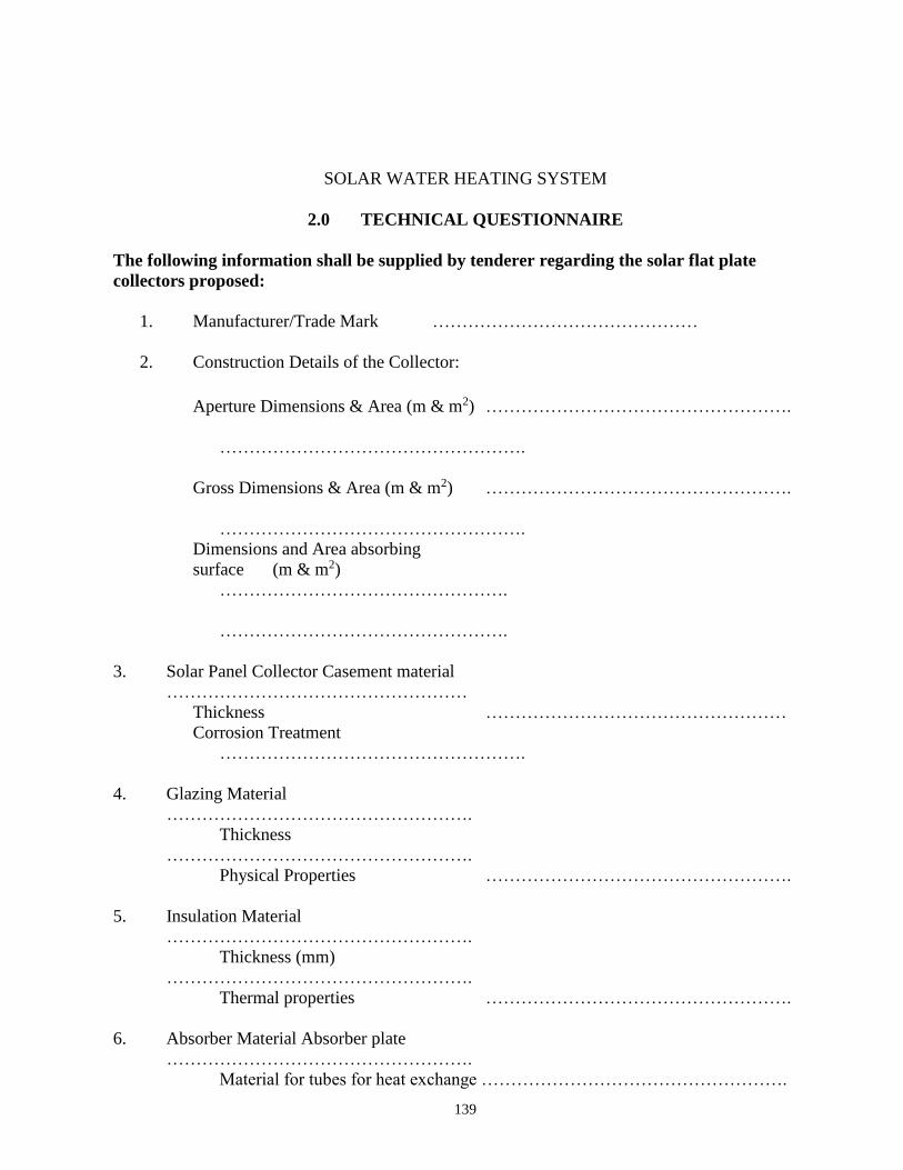
139
SOLAR WATER HEATING SYSTEM
2.0 TECHNICAL QUESTIONNAIRE
The following information shall be supplied by tenderer regarding the solar flat plate
collectors proposed:
1. Manufacturer/Trade Mark ………………………………………
2. Construction Details of the Collector:
Aperture Dimensions & Area (m & m2) …………………………………………….
…………………………………………….
Gross Dimensions & Area (m & m2) …………………………………………….
…………………………………………….
Dimensions and Area absorbing
surface (m & m2)
………………………………………….
………………………………………….
3. Solar Panel Collector Casement material
……………………………………………
Thickness ……………………………………………
Corrosion Treatment
…………………………………………….
4. Glazing Material
…………………………………………….
Thickness
…………………………………………….
Physical Properties …………………………………………….
5. Insulation Material
…………………………………………….
Thickness (mm)
…………………………………………….
Thermal properties …………………………………………….
6. Absorber Material Absorber plate
…………………………………………….
Material for tubes for heat exchange …………………………………………….
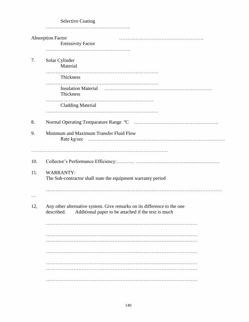
140
Selective Coating
…………………………………………….
Absorption Factor …………………………………………….
Emissivity Factor
…………………………………………….
7. Solar Cylinder
Material
……………………………………………………………
Thickness
……………………………………………………………
Insulation Material …………………………………………………………
Thickness
…………………………………………………………
Cladding Material
……………………………………………………………
8. Normal Operating Temparature Range oC …………………………………………….
9. Minimum and Maximum Transfer Fluid Flow
Rate kg/sec …………………………………………………………………………
…………………………………………………………………………
10. Collector’s Performance Efficiency:……….. ……………………………………………
11. WARRANTY:
The Sub-contractor shall state the equipment warranty period
………………………………………………………………………………………………
…
12, Any other alternative system. Give remarks on its difference to the one
described. Additional paper to be attached if the text is much
…………………………………………………………………………………
…………………………………………………………………………………
…………………………………………………………………………………
…………………………………………………………………………………
…………………………………………………………………………………
…………………………………………………………………………………
…………………………………………………………………………………

141
REPUBLIC OF KENYA
MINISTRY OF PUBLIC WORKS
GENERAL SPECIFICATIONS
FOR
ELECTRICAL INSTALLATION WORKS
ISSUED BY:
CHIEF ELECTRICAL & MECHANICAL ENGINEER (BS) MINISTRY OF PUBLIC WORKS P.O. BOX 41191,
NAIROBI.
142
TABLE OF CONTENTS
TITLE PAGE
SECTION D: General Specifications of Materials and Works..........................143 - 163
SECTION E: Schedule of Contract Drawings................................................. 165
SECTION F: Particular Specifications of Materials and Works.......................166 - 169
SECTION G: Schedule of Unit Rates............................................................ 170
SECTION H: Bills of Quantities................................................................. . 171 - 177
SECTION I: Technical Schedule of Items to be Supplied.............................. 178 - 180
143
SECTION D
GENERAL SPECIFICATION
OF
MATERIALS AND WORKS
144
GENERAL SPECIFICATIONS OF MATERIALS AND WORKS
2.1 General
2.2 Standard of Materials
2.3 Workmanship
2.4 Procurement of Materials
2.5 Shop Drawings
2.6 Record Drawings
2.7 Regulations and Standards
2.8 Setting out Works
2.9 Position of Electrical Plant and Apparatus
2.10 M.C.B Distribution Panels and Consumer Units
2.11 Fused Switchgear and Isolators
2.12 Conduits and Conduit Runs
2.13 Conduit Boxes and Accessories
2.14 Labels
2.15 Earthing
2.16 Cables and Flexible Cords
2.17 Armoured PVC Insulated and Sheathed Cables
2.18 Cable Supports; Markers and Tiles
2.19 PVC Insulated Cables
2.20 Heat Resisting Cables
2.21 Flexible Cords
145
2.22 Cable Ends and phase Colours
2.23 Cable Insulation Colours
2.24 Sub-circuit Wiring
2.25 Space Factor
2.26 Insulation
2.27 Lighting Switches
2.28 Sockets and Switched sockets
2.29 Fused Spur Boxes
2.30 Cooker Outlets
2.31 Connectors
2.32 Lampholders
2.33 Lamps
2.34 lighting Fittings Street lighting Lanterns
2.35 Position of Points and Switches
2.36 Street/Security Lighting Columns
2.37 Timing Control Switch
2.38 Wiring System for Street Lighting
2.39 Metal control Pillar
2.40 Current Operated Earth leakage circuit breaker
2.41 MV Switchboard
2.42 Steel Conduits and Steel Trunking
2.43 Testing on Site
146
2.1 SHOP DRAWINGS
Before manufacture or Fabrication is commenced the sub-contractor shall submit Two
copies of detailed drawings of all control pillars, meter cubicles, medium voltage
switchboards including their components showing all pertinent information including
sizes, capacities, construction details, etc, as may be required to determine the suitability
of the equipment for the approval of the Engineer. Approval of the detailed drawings
shall not relieve the sub-contractor of the full responsibility of errors or the necessity of
checking the drawings himself or of furnishing the materials and equipment and
performing the work required by the plans and specifications.
2.2 RECORD DRAWINGS
These diagrams and drawings shall show the completed installation including sizes, runs
and arrangements of the installation. The drawings shall be to scale not less than 1 :50
and shall include plan views and section.
The drawings shall include all the details which may be useful in the operation,
maintenance or subsequent modifications or extensions to the installation.
Three sets of diagrams and drawings shall be provided, all to the approval of the
Engineer.
One coloured set of line diagrams relating to operating and maintenance instructions shall
be framed and, mounted in a suitable location.
2.3 REGULATIONS AND STANDARDS
All work executed by the Sub-contractor shall comply with the current edition of the
“Regulations” for the Electrical Equipment of Buildings, issued by the Institution of
Electrical Engineers, and with the Regulations of the Local Electricity Authority.
Where the two sets of regulations appear to conflict, they shall be clarified with the
Engineers. All materials used shall comply with relevant Kenya Bureau of Standards
Specification.
147
2.4 SETTING OUT WORK
The sub-contractor at his own expenses; is to set out works and take all measurements and
dimensions required for the erection of his materials on site; making any modifications in
details as may be found necessary during the progress of the works, submitting any such
modifications or alterations in detail to the Engineer before proceeding and must allow in
his Tender for all such modifications and for the provision of any such sketches or
drawings related thereto.
2.5 POSITIONS OF ELECTRICAL PLANT AND APPARATUS
The routes of cables and approximate positions of switchboards etc, as shown on the
drawings shall be assumed to be correct for purpose of Tendering, but exact positions of
all electrical Equipment and routes of cables must be agreed on site with the Engineer
before any work is carried out.
2.6 MCB DISTRIBUTION PANELS AND CONSUMER UNITS
All cases of MCB Panels and consumer units shall be constructed in heavy gauge sheet
with hinged covers.
Removable undrilled gland plates shall be provided on the top and bottom of the cases.
Miniature circuit breakers shall be enclosed in moulded plastic with the tripping
mechanism and arc chambers separated and sealed from the cable terminals.
The operating dolly shall be tripfree with a positive movement in both make and break
position. Clear indication of the position of the handle shall be incorporated.
The tripping mechanism shall be on inverse characteristic to prevent tripping in
temporary overloads and shall not be affected by normal variation in ambient temperature.
A locking plate shall be provided for each size of breaker; A complete list of circuit
details on typed cartridge paper glued to stiff cardboards and covered with a sheet of
perspex, and held in position with four suitable fixings, shall be fitted to the inner face of
the lids of each distribution panel. The appropriate MCB ratings shall be stated on the
circuit chart against each circuit in use: Ivorine labels shall be secured to the insulation
barriers in such a manner as to indicate the number of the circuits shown on the circuit
chart.
Insulated barriers shall be fitted between phases, and neutrals in all boards, and to shroud
live parts.
Neutral cables shall be connected to the neutral bar in the same sequence as the phase
cables are connected to the MCB’s. This shall also apply to earth bars when installed.
148
2.7 FUSED SWITCHGEAR AND ISOLATORS
All fused switchgear and isolators whether mounted on machinery, walls or industrial
panels shall conform to the requirements of KS 04 – 226 PART: 1: 1985.
All contacts are to be fully shrouded and are to have a breaking capacity on manual
operations as required by KS 04 – 182 : 1980.
Fuse links for fused switches are to be of high rupturing capacity cartridge type,
conforming to KS 04 – 183 : 1978.
Isolators shall be load breaking/fault making isolators.
Fused switches and isolators are to have separate metal enclosures. Mechanical interlocks
are to be provided between the door and main switch operating mechanism so arranged
that the door may not be opened with the switch in the ‘ON’ position. Similarly; it shall
not be possible to close the switch with the door open except that provision to defeat the
mechanical interlock and close the switch with the door in the open position for test
purposes. The ‘ON’ and ‘OFF’ positions of all switches and isolators shall be clearly
indicated by a mechanical flag indicator or similar device. In T.P & N fused switch
units, bolted neutral links are to be fitted.
2.8 CONDUITS AND CONDUIT RUNS
Conduit systems are to be installed so as to allow the loop-in system of wiring:
All conduits shall be black rigid super high impact heavy gauge class ‘A’ PVC in
accordance with KS 04 – 179: 1988 and IEE Regulations. No conduit less than 20mm in
diameter shall be used anywhere in this installation.
Conduit shall be installed buried in plaster work and floor screed except when run on
wooden or metal surface when they will be installed surface supported with saddles every
600mm. Conduit run in chases shall be firmly held in position by means of substantial
pipe hooks driven into wooden plugs.
The Sub-contractors attention is drawn to the necessity of keeping all conduits entirely
separate from other piping services such as water and no circuit connections will be
permitted between conduits and such pipes.
All conduits systems shall be arranged wherever possible to be self-draining to switch
boxes and conduit outlet points for fittings:
The systems, when installed and before wiring shall be kept plugged with well fitting
plugs and when short conduit pieces are used as plugs, they shall be doubled over and tied
firmly together with steel wire; Before wiring all conduit systems shall be carried out
until the particular section of the conduit installation is complete in every respect.
The sets and bends in conduit runs are to be formed on site using appropriate size bending
springs and all radii of bends must not be less than 2.5 times the outside diameter of the
149
conduit. No solid or inspection bends, tees or elbows will be used.
Conduit connections shall either be by a demountable (screwed up) assembly or adhesive
fixed and water tight by solution. The tube and fittings must be clean and free of all
grease before applying the adhesive. When connections are made between the conduit
and switch boxes, circular or non-screwed boxes, care shall be taken that no rough edges
of conduit stick out into the boxes.
Runs between draw in boxes are not to have more than two right angle bends or their
equivalent . The sub-contractor may be required to demonstrate to the Engineers that
wiring in any particular run is easily withdrawable and the sub-contractor may, at no extra
cost to the contract; be required to install additional draw-in boxes required. If conduit is
installed in straight runs in excess of 6000mm, expansion couplings as manufactured by
Egatube shall be used at intervals of 6000mm.
Where conduit runs are to be concealed in pillars and beams, the approval of the
Structural Engineer, shall be obtained. The sub-contractor shall be responsible for
marking the accurate position of all holes, chases etc, on site, or if the Engineer so directs,
shall provide the Main Contractor with dimensional drawings to enable him t o mark out
and form all holes and chases. Should the sub-contractor fail to inform the main
contractor of any inaccuracies in this respect they shall be rectified at the sub-contractors
expense.
It will be the Sub-contractors responsibility to ascertain from site, the details of reinforced
concrete or structural steelwork and check from the builder’s drawings the positions of
walls, structural concrete and finishes. No reinforced concrete or steelwork may be
drilled without first obtaining the written permission of the Structural Engineer.
The drawings provided with these specifications indicate the appropriate positions only
of points and switches, and it shall be the Sub-Contractors responsibility to mark out and
centre on site the accurate positions where necessary in consultation with the Architect
and the Engineer. The sub-contractor alone shall be responsible for the accuracy of the
final position.
2.13 CONDUIT BOXES AND ACCESSORIES
All conduit outlets and junction boxes are to be either malleable iron and of standard
circular pattern of the appropriate type to suit saddles being used or super high impact
PVC manufactured to KS 04 – 179 : 1983.
Small circular pattern boxes are to be used with conduits up to and including 25mm
outside diameter. Rectangular pattern adaptable boxes are to be used for conduits of
32mm outside diameter and larger. For drawing in of cables in exposed runs of conduit,
standard pattern through boxes are to be used:
Boxes are to be not less than 50mm deep and of such dimensions as will enable the largest
appropriate number of cables for the conduit sizes to be drawn in without excessive
bending.
150
Outlet boxes for lighting fittings are to be of the loop-in type where conduit installation is
concealed and the sub-contractor shall allow one such box per fitting, except where
fluorescent fittings are specified when two such boxes per fitting shall be fitted flush with
ceiling and if necessary fitted with break joint rings. Pattresses shall be fitted where
required to outlets on surface conduit runs.
Adaptable boxes are to of PVC or mild steel (of not less than 12swg) and black
enamelled or galvanised finish according to location. They shall be of square or oblong
shape location. They shall be of square or oblong shape complete with lids secured by
four 2 BA brass roundhead screws; No adaptable box shall be less than 75mm x 75mm x
50mm or larger than 300mm x 300mm x 75mm and shall be adequate in depth in relation
to the size of conduit entering it. Conduits shall only enter boxes by means of conduit
bushes.
2.14 LABELS
Labels fitted to switches and fuseboards;-
(i) Shall be Ivorine engraved black on white.
(ii) Shall be secured by R.H brass screws of same manufacturing throughout.
(iii) Shall be indicated on switches:-
a) Reference number of switch
b) Special current rating
c) Item of equipment controlled
(iv) Shall indicate on MCB panels
a) Reference number
b) Type of board, i.e;, lighting, sockets, etc,.
c) Size of cable supplying panel
d) where to isolate feeder cable
(v) Shall be generally not less than 75mm x 50mm.
2.15 EARTHING
The earthing of the installation shall comply with the following requirements;-
(i) It shall be carried out in accordance with the appropriate sections of the current
edition of the Regulations, for the Electrical Equipment of Buildings issued by
Institute of Electrical Engineers of Great Britain.
(ii) At all main distribution panels and main service positions a 25mm x 3mm
minimum cross sectional area Copper tape shall be provided and all equipment
including the lead sheath and armouring of cables, distribution boards and metal
frames shall be bonded thereto.
151
(iii) The earth tape in Sub-clause (ii) shall be connected by means of a copper tape or
cable of suitable cross sectional area to an earth electrode which shall be a copper
earth rod (see later sub-clause).
(iv) All tapes to be soft high conductivity copper, untinned except where otherwise
specified and where run underground on or through walls, floors, etc., it shall be
served with corrosion resisting tape or coated with corrosion compound and
braided
(v) Where the earth electrode is located outside the building a removable test link
shall be provided inside the building as near as possible to the point of entry to the
tape, for isolating the earth electrode for testing purposes.
(vi) Earthing of sub-main equipment shall be deemed to be satisfactory where the sub-
main cables are M.I.C.S. or conduit with separate earth wire, and installation is
carried out in accordance with the figures stated in the current edition of the I.E.E
Regulations.
(vii) Where an earth rod is specified (see Sub-clause (iii) it shall be proprietary
manufacture, solid hand drawn copper of 15mm diameter driven into the ground to
a minimum depth of 3.6m . It shall be made up to 1.2m sections with internal
screw and socket joints and fitted with hardened steel tip and driving cap.
(viii) Earth plates will not be permitted
(ix) Where an earth rod is used the earth resistance shall be tested in the manner
described in the current edition of the IEE Regulations, by the Sub-Contractor in
the presence of the Engineer and the Sub-Contractor shall be responsible for the
supply of all test equipment.
(x) Where copper tape is fixed to the building structure it structure it shall be by
means of purpose made non-ferrous saddles which space the conductor away from
the structure a minimum distance of 20mm. Fixings, shall be made using purpose
made plugs; No fixings requiring holes to be drilled through the tape will be
accepted.
(xi) Joints in copper tape shall be tinned before assembly riveted with a minimum of
two copper rivets and seated solid.
(xii) Where holes are drilled in the earth tape for connection to items of equipment the
effective cross sectional area must not be less than required to comply with the
IEE regulations.
(xiii) Bolts, nuts and washers for any fixing to the earth tape must be of non-ferrous
material.
(xiv) Attention is drawn to the need for the earthing metal parts of lighting fittings and
for bonding ball joint suspension in lighting fittings.
152
2.16 CABLES AND FLEXIBLE CORDS
All cables used in this Sub-Contract shall be manufactured in accordance with the current
appropriate Kenya standard Specification which are as follows:-
P.V.C. Insulated Cables and Flexible Cords - Ks 04-192:1988
PVC Insulated Armoured Cables - Ks 04-194:1990
Armouring of Electric cables - Ks 04-290:1987
The successful Sub-Contractor will, at the Engineers discretion be required to submit
samples of cables for the Engineers approval; the Engineer reserves the right to call for
the cables of an alternative manufacture without any extra cost being incurred.
P.V.C. insulated cables shall be 500/1000 volt grade. No cables smaller than 1.5mm²
shall be used unless otherwise specified. The installation and the finish of cables shall be
as detailed in later clauses. The colour of cables shall conform with the details stated in
the “Cable Braid and insulation Colours” Clause.
2.17 ARMOURED P.V.C. INSULATED AND SHEATHED CABLES:
Shall be 600/1000 volt grade manufactured to Ks 04-194:1988 and Ks 04-187/188 with
copper stranded conductors.
The wire armour of the cable shall be used wholly as an earth continuity conductor and
the resistance of the wire armour shall have a resistance not more than twice of the largest
current carrying conductor of the cable.
P.V.C./S.W.A./P.V.C. cables shall be terminated using “Telecom” “B” type or approved
equal or approved equal glands and a P.V.C. tapered sleeve shall be provided to shroud
each gland.
Where cables rise from floor level to switchgear etc., they shall be protected by P.V.C.
conduit, to a height of 600mm from finished floor level, whether the cable is run on the
surface or recessed into the wall.
2.18 CABLE SUPPORTS, MARKERS AND TILES
All PVC/SWA/PVC cables run inside the building shall be fixed in rising ducts or on
ceilings by means of die cost cables hooks or clamps, or appropriate size to suit cables,
fixed by studs and back nuts to their channel sections.
Alternatively, fixing shall be by BICC claw type cleating system with die-cast cleats and
galvanized mild steel back straps or similar approved equal method. For one or two
cables run together the cleats shall be fixed a special channel section supports or
backstraps described above which shall in turn be secured to walls or ceilings of ducts by
rawbolts.
In excessively damp or corrosive atmospheric conditions special finishes may be required
and the Sub-contractor shall apply to the Engineer for further instructions before ordering
153
cleats and channels for such areas.
The above type of hooks and clamps and channels or cleats and blackstraps shall also be
used for securing cables in vertical ducts.
Cables supports shall be fixed at 600mm maximum intervals, the supports being supplied
and erected under this Sub-contract. Saddles shall not be used for supporting cables nor
any other type of fixing other than one of the two methods described above or other
system which has received prior approval of the Engineer;
Cables are to be kept clear of all pipe work and the Sub-contractor shall work in close
liaison with other services Sub-contractors.
The Sub-Contractor shall include for the provision of fixing of approved type coloured
slip on cables end markers to indicate permanently the correct phase and neutral colours
on all ends.
Provision shall be made for supplying and fixing approved non-corrosive metal cable
markers to be attached to the outside of all PVC/SWA/PVC cables at 15mm intervals
indicating cable size and distinction.
Where PVC/SWA/PVC cables are outside the building they shall be laid underground
750mm deep with protecting concrete interlocking cover tiles laid over which shall be
provided and laid under this Sub-contract.
All necessary excavations and reinstatement of ground including sanding or trenches will
be carried out by the Sub-Contractor, unless otherwise stated.
2.19 PVC INSULATED CABLES Shall be of non-braided type as CMA reference 6491 x 600/1000/1000 volt grade cables,
or equal approved.
PVC cables shall conform to the details of the “Cables and Flexible cords” and “Cable
Braid and Insulation Colours” clauses.
2.20 HEAT RESISTING CABLES Final connections to cookers, water heaters, etc., shall be made using butyl rubber
insulated cable as CMA reference 610 butyl (Single core 600/1000 Volt).
This type of cable shall be used in all instances where a temperature exceeding 100°F, but
not exceeding 150°F is likely to be experienced. Final connections to all lighting fittings
(and other equipment where a temperature in excess of 150°c likely to be experienced)
shall be made using silicon rubber insulated cable or equal and approved.
2.21 FLEXIBLE CORDS
Shall be in accordance with the “Cable and Flexible Cords” clause. No cord shall be less
than 24/0.2mm in size unless otherwise specified.
Circular white twin TRS flex shall be used for plain pendant fittings up to 100 watts. For
154
all other types of lighting fittings the flexible cable shall be silicone rubber insulated.
No polythene insulated flexible cable shall be used in any lighting fitting or other
appliance (see “Heat Resisting Cables” Clause 30).
2.22 CABLE ENDS AND PHASE COLOURS
All cable ends connected up in switchgear, MCB panels etc;, shall have the insulation
carefully cut back and the ends sealed with Hellerman rubber slip on cable end markers.
The markers shall be of appropriate phase colour for switch and all other live feeds to the
details of the “Cable Insulation Colours” clause. Black cable with black end markers
shall only be used for neutral cables.
2.23 CABLE INSULATION COLOURSUnless otherwise stated in later clauses the
insulation colours shall be in accordance with the following table.
Where other systems are installed the cable colours shall be in accordance with the details
stated in the appropriate clause.
SYSTEM INSULATION COLOUR CABLE END
MARKER
Main and Sub-Main
a) Phase Red Red
b) Neutral Black Black
1) Sub-Circuits
Single Phase
a) Phase Red Red
b) Neutral Black Black
2.24 SUB-CIRCUIT WIRING
For all lighting and sockets wiring shall be carried out in the “looping in” system and
there shall be no joints whatsoever. No lighting circuits shall comprise more than 20
points when protected by 10A MCB. Cables with different cross-section area of copper
shall not be used in combination.
155
Lighting circuits P. V.C. cable 1.5mm² for all lighting circuits indicated on the drawing.
Power circuits P.V.C cable (minimum sizes).
(i) 2.5mm² for one, two or three 5Amp sockets wired in parallel.
(ii) 2.5mm² for one 15Amp socket.
(iii) 2.5mm² for maximum of ten switched 13 Amp sockets wired from 30 Amp MCB.
The wiring sizes for lighting circuits and sockets are shown on the drawings. In such
cases, the sizes shown on the drawings shall prevail over the sizes specified.
Wiring sizes for other appliances shall be shown on the drawing or specified in later
clauses of this specification.
2.25 SPACE FACTOR
The maximum number of cables that may be accommodated in a given size of conduit or
trunking or duct is not to exceed the number in Tables B.5 and B.6 or as stated in
Regulation B.91, B.117 and B.118 of the I.E.E Regulations whichever is appropriate.
2.26 INSULATION
The insulation resistance to earth and between poles of the whole wiring system, fittings
and lumps, shall not be less than the requirements of the latest edition of the I.E.E
Regulations. Complete tests shall be made on all circuits by the Sub-contractor before the
installations are handed over.
A report of all tests shall be furnished by the Sub-Contractor to the Engineer. The
Engineer will then check test with his own instruments if necessary.
2.27 LIGHTING SWITCHES
These shall be mounted flush with the walls, shall be contained in steel or alloy boxes and
shall be of the gangs ratings and type shown in the drawings. They shall be as
manufactured by M.K. Electrical Ltd., or other equal and approved to KS 04 – 247: 1988
2.28 SOCKETS AND SWITCHED SOCKETS
These shall be flush pattern in steel/pvc box and shall be of the gangs and type specified
in the drawings.
They shall be 13- Amp, 3-pin, shuttered, switched and as manufactured by “M.K.
Electrical Co. Ltd.”, or other approved equal to KS 04 – 246: 1987
2.29 FUSED SPUR BOXES
These shall be flush, D.P switched as in steel/pvc box and of type and make specified in
the drawings complete with pilot light and as manufactured by “M. K. Electrical
Company Ltd”, or other approved equal. KS 04 – 247: 1988
156
2.30 COOKER OUTLETS
These shall be flush mounted with 13-A switched socket outlet and neon indicator Lamps.
The cooker control units shall be as manufactured by “M.K. Electrical Company Ltd”, or
other approved equal KS 04 – 247: 1988
2.31 CONNECTORS
Shall be specified in the drawings and appropriate rating. These shall be fitted at all
conduit box lighting point outlets for jointing of looped P.V.C cables with flexible cables
of specified quality.
2.32 LAMPHOLDERS
Shall be of extra heavy H.O skirted and shall be provided for every specified lighting
fitting and shall be B.C;, E.S;, or G.E.S as required. All E.S. and G.E.S. holders shall be
heavy brass type (except for plain pendants where the reinforced bakelite type shall be
used). The screwed cap of the E.S and G.E.S. holders shall be connected to the neutral.
Where lampholders are supported by flexible cable, the holders shall have “cord grip”
arrangements and in the case of metal shades earthing screws shall be provided on each of
the holders.
The Sub-Contractor must order the appropriate type of holder when ordering lighting
fittings, to ensure that the correct types of holders are provided irrespective of the type
normally supplied by the manufacturers.
2.33 LAMPS
All lamps shall be suitable for normal stated supply voltage and the number and sizes of
lamps detailed on the drawings shall be supplied and fixed. The Sub-Contractor must
verify the actual supply voltage with the supply authority before ordering the lamps.
Tungsten filament lamps shall be manufactured in accordance with KS 04 – 112:1978 for
general service lamps and KS 04 – 307:1985 for lamps other than general services.
Tubular fluorescent lamps shall comply with KS 04 – 464:1982
Pearl lamps shall be used in all fittings unless otherwise specified.
2.34 LIGHTING FITTINGS AND STREET LIGHTING LANTERNS This Sub-Contract shall include for the provision, handling charges, taking the delivery,
safe storage, wiring (including internal wiring) assembling and erecting of all lighting
fittings shown on the drawings.
All fittings and pendants shall be fixed to the conduit boxes with brass R/H screws. These
to be in line with metal finish of fittings. The lighting fittings are detailed for the purpose
of establishing a high standard of finish and under no circumstances will substitute fittings
be permitted.
In case of rectangular shaped ceiling fittings, the extreme ends of the fittings shall be
secured to suitable support in addition to the central conduit box fittings. Supports shall
be provided and fixed by the Sub-Contractor.
157
The whole of the metal work of each lighting fittings shall be effectively bonded to earth.
In the case of ball and/or knuckle joints short lengths of flexible cable shall be provided,
bonded to the metal work on either side of the joints. If the above provisions are not made
by the manufacturers -, the Sub-contractor shall include cost of additional work necessary
in his tender. See “Flexible Cords” clause for details of internal wiring of lighting fittings.
Minimum size of internal wiring shall be 20/0.20mm (23/0067). Each lighting fitting
shall be provided with number type and size of lamps as detailed on the drawings. It is to
be noted that some fittings are suspended as shown on the drawings.
Where two or more points are shown adjacent to each other on the drawings, e.g socket
outlet and telephone outlet, they shall be lined up vertically or horizontally on the centre
lines of the units concerned
Normally, the units shall be lined up on vertical centre lines, but where it is necessary to
mount units at low level they shall be lined up horizontally.
2.35 POSITIONS OF POINTS AND SWITCHES
Although the approximate positions of all points are shown on the drawings, enquiry shall
be made as to the exact positions of all M.C.B panels, lighting points, socket outlets etc,
before work is actually commenced. The Sub-contractor must approach the Architect
with regard to the final layout of all lights on the ceiling and walls.
The Sub-contractor must consult with the Engineer in liaison with the Clerk of Works, or
the General Foreman on site regarding the positions of all points before fixing any conduit
etc. The Sub-Contractor shall be responsible for all alterations made necessary by the
non-compliance with the clause.
2.36 STREET/SECURITY OUTDOOR LIGHTING COLUMNS:
The column shall be at a minimum of 225mm in the ground on 75mm thick concrete
foundations and the pole upto 150mm shall be surrounded with concrete. The top bracket
and plain section of the columns shall be common to and interchangeable with all brackets
with maximum mismatching tolerance of 3mm between any pole and bracket. After
manufacture and before erection the columns shall be treated with an approved mordant
solution which shall be washed off and the whole allowed to dry. Thereafter, the columns
shall be painted with one undercoat and two coats of gloss paint to an approved colour.
All columns shall be complete with fused cut-outs.
2.37 TIMING CONTROL SWITCH
These shall be installed where shown on the drawings. Photocell timing control circuits
which will operate ‘on’ with a specified level of darkness and ‘off’ with a given level of
light. The initial adjustment will be done with approval of the Electrical Engineer.
158
2.38 WIRING SYSTEM FOR STREETLIGHTING
Cables shall be as indicated on the drawings, and shall be laid in a cable trench 450mm
deep along the road sides and 600mm deep across the roads and 900mm away from the
road kerb or 1500mm away from the edges of the road. ‘Loop-in’ and ‘Loop-out’
arrangement shall be used at every pole. Wiring to the lanterns on each pole shall be with
1.5mm² PVC twin insulated and sheathed cable with earth wire shall be laid at least
600mm below the finished road level on a compact bed of murram at least 50mm thick
and covered with a concrete surrounded 150mm thick.
2.39 METAL CONTROL PILLAR
These shall be metal clad and fabricated as per contract drawings and specification. The
Sub-Contractor shall supply, install, test and commission control pillars including
supplying, fixing connecting switchgears as detailed on the appropriate drawings.
2.40 CURRENT OPERATED EARTH LEAKAGE CIRCUIT BREAKER
Current operated earth leakage circuit breaker shall conform to B.S.S. 4293:68 rated at
240 volts D.P. 50 cycles A.C. Mains.
The breaker shall be provided with test switch and fitted in weather proof enclosure for
surface mounting. The rated load current and earth fault operating current shall be as
specified in the drawings. These shall be as manufactured by Crabtree, Siemens or other
equal and approved.
2.41 M.V. SWITCHBOARD AND SWITCHGEAR
The switchboard shall be manufactured in accordance with KS04-226 which co-ordinates
the requirements for electrical power switchgear and associated apparatus. It is not
intended that this K.S. should cover the requirements for specified apparatus for which
separate Kenyan Standard exist. All equipment and material used in the switchboard shall
be in accordance with the appropriate Kenya Standard.
The switchboard shall comprise the equipment shown on the drawings together with all current
transformers, auxiliary fuses, labels, small wiring and interconnections necessary for the
satisfactory operation of the switchboard
159
Switchboard shall be of the flush fronted, enclosed, metal clad type with full front or rear access as called for in the particular specifications, suitable for indoor use, sectionalized as necessary to facilitate transport and erection. The maximum height of the switchboard is to be approximately 2.0 meters. A suitable connection chamber containing all field terminals shall be provided at the top or bottom of the switchboard as appropriate.
Before manufacture, the Sub-Contractor shall submit to the consulting Engineer for
approval of detailed drawings showing the layout, construction and connection of the
switchboard.
All bus-bars and bus-bar connections shall consist of high conductivity copper and be
provided in accordance with KS 04-226: 1985. The bus-bars shall be clearly marked with
the appropriate phase and neutral colours which should be red, yellow, blue for the phases
and black for neutral. The bus-bars shall be so arranged in the switchboard that the
extensions to the left and right may be made in the future with ease should the need arise.
Small wiring, which will be neatly arranged and cleated, shall be executed in accordance
with B.S. 158 and the insulation of the wiring shall be colored according to the phase or
neutral connection.
Switches and fuse switches, shall be in strict accordance with KS04-183:1978 Class 2
switches. Means of locking the switch in the “OFF” position shall be provided.
All fuse switches shall comply with KS04-183:1978, PARTS 2 and 3 a fault rating at least
equal to the fault rating of the switchboard in which they are installed. Cartridge fuse
links to KS 04-183:1978 category A.C. 46, class Q1 and fusing factor not exceeding 1.5
shall be supplied with each fused switch.
Mounting arrangements shall be such that individual complete fuse switches may be
disconnected and withdrawn when necessary without extensive dismantling work. When
switches are arranged in their formation all necessary horizontal and vertical barriers shall
be provided to ensure segregation from adjacent units. Means of locking the switch in the
“OFF” position shall be provided.
160
2.42 STEEL CONDUITS AND STEEL TRUNKING
Conduits shall be of heavy gauge class “B” welded to Standard specification KS 04-
180:1985. In no case will conduit smaller than 20mm diameter be used on the works.
Conduits installed within buildings shall be black enameled finish except where specified
otherwise. Where installed externally or in damp conditions they shall be galvanised.
Conduit fittings, accessories or equipment used in conjunction with galvanised conduits
shall also be galvanised or otherwise as approved by the service engineer.
Metal trunking shall be fabricated from mild steel of not less than 18 swg. All sections of
trunking shall be rigidly fixed together and attached to the framework or fabric or the
building at intervals of not less than 1.2m. Joint trunking shall not overhang fixing points
by more than 0.5m.
All trunking shall be made electrically continuous by means of 25 x 3mm copper links
across each joint and where the trunking is galvanised, the links shall be made by
galvanised flat iron strips.
All trunking fittings (i.e. Bends, tees, etc) shall leave the main through completely clear
of obstructions and continuously open except through walls and floors at which points
suitable fire resisting barriers shall be provided as may be necessary. The inner edge of
bends and tees shall be chamfered where cables larger than 35mm² are employed.
Where trunking passes through ceilings and walls the cover shall be solidly fixed to
150mm either side of ceilings and floors and 50mm either side of walls.
Screws and bolts securing covers to trunking or sections of covers together shall be
arranged so that damage to cables cannot occur either when fixing covers or when
installing cables in the trough.
Where trunking is used to connect switchgear of fuseboards, such connections shall be
made by trunking fittings manufactured for this purpose and not by multiple conduit
couplings.
Where vertical sections of trunking are used which exceed 4.5m in length, staggered tie
off points shall be provided at 4.5m intervals to support the weight of cables.
Unless otherwise stated, all trunking systems shall be painted as for conduit.
161
Where a wiring system incorporates galvanized conduit and trunking, the trunking shall be deemed to be galvanized unless specified otherwise.
The number of cables to be installed in trunking shall be such as to permit easy drawing in
without damage to the cables, and shall in no circumstances be such that a space factor of
45% is exceeded.
Conduit and trunking shall be mechanically and electrically continuous. Conduit shall be
tightly screwed between the various lengths so that they butt at the socketed joints. The
internal edges of conduit and all fittings shall be smooth, free from burrs and other
defects. Oil and any other insulating substance shall be removed from the screw threads;
where conduits terminate in fuse-gear, distribution boards, adaptable boxes, non-spouted
switchboxes, etc., they shall, unless otherwise stated, be connected thereto by means of
smooth bore male brass bushes, compression washers and sockets. All exposed threads
and abrasions shall be painted using an oil paint for black enamelled tubing and
galvanising paint for galvanised tubing immediately after the conduits are erected. All
bends and sets shall be made cold without altering the section of the conduit. The inner
radius of the bed shall not be less than four (4) times the outside diameter of the conduit.
Not more than two right angle bends will be permitted without the inter-position of a
draw-in-box. Where straight runs of conduit are installed, draw-in-boxes shall be
provided at distances not exceeding 15mm. No tees, elbows, sleeves, either of inspection
or solid type, will be permitted.
Conduit shall be swabbed out prior to drawing in cables, and they shall be laid so as to
drain of all condensed moisture without injury to end connections.
Conduits and trunking shall be run at least 150mm clear of hot water and steam pipes, and
at least 75mm clear of cold water and other services unless otherwise approved by the
services engineer.
All boxes shall conform to KS 04 – 668: 1986, to be of malleable iron, and black
enamelled or galvanised according to the type of conduit specified. All accessory boxes
shall have threaded brass inserts.
Box lids where required shall be heavy gauge metal, secured by means of zinc plated or
cadmium plated steel screws.
All adaptable boxes and lids of the same size shall be interchangeable.
Boxes used on surface work are to be tapped or drilled to line up with the conduit fixed in
distance type saddles allowing clearance between the conduit and wall without the need
for setting the conduit.
162
Where used in conjunction with mineral insulated copper sheathed cable, galvanised
boxes shall be used and painted after erection.
Draw-in boxes in the floors are generally to be avoided but where they are essential they
must be grouped in positions approved by the services engineer and covered and by the
suitable floor traps, with non-ferrous trays and covers.
The floor trap covers are to be recessed and filled in with a material to match the floor
surface.
The Sub-contractor must take full responsibility for the filling in of all covers, but the
filling in material will be supplied and the filling carried out by the main building
contractor.
Where buried in the ground outside the building the whole of the buried conduit is to be
painted with two coats of approved bitumastic composition before covering up.
Where run on the surface, unpainted fittings and joints shall be painted with two coats of
oil bound enamel applied to rust and grease free metalwork.
2.43 TESTING ON SITE The Sub-contractor shall conduct during and at the completion of the installation and, if
required, again at the expiration of the maintenance period, tests in accordance with the
relevant section of the current edition of the Regulations for the electrical equipment of
buildings issued by the I.E.E of Great Britain, the Government Electrical Specification
and the Electric Supply Company’s By-Laws.
(a) Tests shall be carried out to prove that all single pole switches are installed in the
‘live’ conductor.
(b) Tests shall be carried out to prove that all socket outlets and switched socket outlets
are connected to the ‘live’ conductor in the terminal marked as such, and that each
earth pin is effectively bonded to the earth continuity system. Tests shall be carried
out to verify the continuity of all conductors of each ‘ring’ circuit.
(c) Phase tests shall be carried out on completion of the installation to ensure that correct
phase sequence is maintained throughout the installation. Triplicate copies of the
results of the above tests shall be provided within 14 days of the witnessed tests and
the Sub-contractor will be required to issue to the service engineer the requisite
certificate upon completion as required by the regulations referred to above.
163
(d) Any faults, defects or omissions or faulty workmanship, incorrectly positioned or installed
parts of the installation made apparently by such inspections or tests shall be rectified by the
Sub-contractor at his own expense.
(e) The Sub-contractor shall provide accurate instruments and apparatus and all labour
required to carry out the above tests. The instruments and apparatus shall be made
available to the services engineer to enable him to carry out such tests as he may
require.
The Sub-contractor shall generally attend on other contractors employed on the project
and carry out such electrical tests as may be necessary.
The Sub-contractor shall test to the services engineer’s approval and as specified
elsewhere in this specification or in standards and regulations already referred to, all
equipment, plant and apparatus forming part of the works and before connecting to any
power or other supply and setting to work.
Where such equipment, etc., forms part of or is connected to a system whether primarily
or of an electrical nature or otherwise ( e.g. air conditioning system) the Sub-contractor
shall attend on and assist in balancing, regulating testing and commissioning, or if
primarily an electrical or other system forming part of works, shall balance, regulate, test
and commission the system to the service engineer’s approval.

164
APPENDIX TO GENERAL SPECIFICATIONS OF MATERIALS AND WORKS
The electrical sub-contractor shall comply with the following:-
1. Government Electrical Specifications No. 1 and No. 2.
2. All requirements of Kenya Power and Lighting Company Limited, and
Communications Commission of Kenya (CCK).

165
SECTION E
SCHEDULE OF CONTRACT DRAWINGS

166
SCHEDULE OF CONTRACT DRAWINGS
167
SECTION F
PARTICULAR SPECIFICATIONS
OF
MATERIALS AND WORKS

168
PARTICULAR SPECIFICATIONS
1.0 SITE LOCATION
The site of the proposed works is at (As stated in the Particular Preliminaries)
2.0 SCOPE OF WORKS
The works to be carried out under this sub-contract comprise supply, installation, testing
and commissioning of the following:-
Electrical Works
This shall include: -
a. Electrical Installation Works.
b. Fire Alarm System Works.
c. Telephone points complete with CAT 5E cable wiring
d. Computer points.
This shall be as specified in the bills of quantities and to the approval of the Electrical
Engineer.
3.0 MATERIALS FOR THE WORKS
Materials shall be as specified in Section D and in the Bills of Quantities of this
document which shall be read in conjunction with contract drawings. Alternative materials
shall be accepted only after approval by the Project Manager.
169
SECTION G
SCHEDULE OF UNIT RATES
170
SCHEDULE OF UNIT RATES
1. The tenderer shall insert unit rates against the items in the following schedules and may add
such other items as he considers appropriate.
2. The unit rates shall include for supply, transport, insurance, delivery to site, storage as
necessary, assembling, cleaning, installing, connecting, profit and maintenance in defects
liability and any other obligation under this contract.
3. The unit rates will be used to assess the value of additions or omissions arising from
authorised variations to the contract works.
4. Where trade names or manufacturer’s catalogue numbers are mentioned in the
specification, the reference is intended as a guide to the type of article or quality of material
required. Alternative brands of equal and approved quality will be accepted.
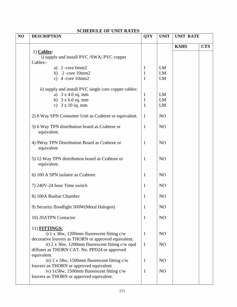
171
SCHEDULE OF UNIT RATES
NO DESCRIPTION QTY UNIT UNIT RATE
1) Cables:
i) supply and install PVC /SWA/ PVC copper
Cables:-
a) 2 -core 6mm2
b) 2 -core 10mm2
c) 4 -core 10mm2
ii) supply and install PVC single core copper cables:
a) 3 x 4.0 sq. mm
b) 3 x 6.0 sq. mm
c) 3 x 10 sq. mm
.
2) 8 Way SPN Consumer Unit as Crabtree or equivalent.
3) 6 Way TPN distribution board as Crabtree or
equivalent.
4) 9Way TPN Distribution Board as Crabtree or
equivalent
5) 12 Way TPN distribution board as Crabtree or
equivalent.
6) 100 A SPN isolator as Crabtree.
7) 240V-24 hour Time switch
8) 100A Busbar Chamber
9) Security floodlight 500W(Metal Halogen)
10) 20ATPN Contactor
11) FITTINGS:
i) 1 x 36w, 1200mm fluorescent fitting c/w
decorative louvers as THORN or approved equivalent.
ii) 2 x 36w, 1200mm fluorescent fitting c/w opal
diffuser as THORN CAT. No. PPD24 or approved
equivalent.
iii) 2 x 58w, 1500mm fluorescent fitting c/w
louvers as THORN or approved equivalent
iv) 1x58w, 1500mm fluorescent fitting c/w
louvers as THORN or approved equivalent.
1
1
1
1
1
1
1
1
1
1
1
1
1
1
1
1
1
1
1
LM
LM
LM
LM
LM
LM
NO
NO
NO
NO
NO
NO
NO
NO
NO
NO
NO
NO
NO
KSHS CTS

172
SECTION H
BILLS OF QUANTITIES
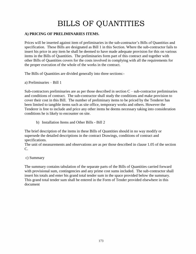
173
BILLS OF QUANTITIES
A) PRICING OF PRELIMINARIES ITEMS.
Prices will be inserted against item of preliminaries in the sub-contractor’s Bills of Quantities and
specification. These Bills are designated as Bill 1 in this Section. Where the sub-contractor fails to
insert his price in any item he shall be deemed to have made adequate provision for this on various
items in the Bills of Quantities. The preliminaries form part of this contract and together with
other Bills of Quantities covers for the costs involved in complying with all the requirements for
the proper execution of the whole of the works in the contract.
The Bills of Quantities are divided generally into three sections:-
a) Preliminaries – Bill 1
Sub-contractors preliminaries are as per those described in section C – sub-contractor preliminaries
and conditions of contract. The sub-contractor shall study the conditions and make provision to
cover their cost in this Bill. The number of preliminary items to be priced by the Tenderer has
been limited to tangible items such as site office, temporary works and others. However the
Tenderer is free to include and price any other items he deems necessary taking into consideration
conditions he is likely to encounter on site.
b) Installation Items and Other Bills - Bill 2
The brief description of the items in these Bills of Quantities should in no way modify or
supersede the detailed descriptions in the contract Drawings, conditions of contract and
specifications.
The unit of measurements and observations are as per those described in clause 1.05 of the section
C.
c) Summary
The summary contains tabulation of the separate parts of the Bills of Quantities carried forward
with provisional sum, contingencies and any prime cost sums included. The sub-contractor shall
insert his totals and enter his grand total tender sum in the space provided below the summary.
This grand total tender sum shall be entered in the Form of Tender provided elsewhere in this
document

174
B) NOTES FOR BILLS OF QUANTITIES
1. The Bills of Quantities form part of the contract documents and are to be read in
conjunction with the contract drawings and general specifications of materials and works.
2. The prices quoted shall be deemed to include for all obligations under the sub-contract
including but not limited to supply of materials, labour, delivery to site, storage on site,
installation, testing, commissioning and all taxes.
In accordance with Government policy, the 16% V.A.T and 3% withholding Tax shall be
deducted from all payments made to the tenderer, and the same shall be forwarded to the
Kenya Revenue Authority (KRA).
3 All prices omitted from any item, section or part of the Bills of Quantities shall be
deemed to have been included to another item, section or part.
4. The brief description of the items given in the Bills of Quantities are for the purpose of
establishing a standard to which the sub-contractor shall adhere to. Otherwise alternative
brands of equal and approved quality will be accepted.
Should the sub-contractor install any material not specified here in before receiving
approval from the Project Manager, the sub-contractor shall remove the material in
question and, at his own cost, install the proper material.
5. The grand total of prices in the price summary page must be carried forward to the Form of
Tender.
6. Tenderers may enclose, together with their submitted tenders, detailed manufacturer’s
brochures detailing Technical Literature and specifications of the items they intend to
offer.
The brochures shall be used in the tender evaluation to determine the first line
aesthetics and quality of fittings offered.
175
1. Statement of Compliance
I confirm compliance of all clauses of the General Conditions, General Specifications and
Particular Specifications in this tender.
I confirm I have not made and will not make any payment to any person, who can be
perceived as an inducement to win this tender.
Signed: …………………………………….for and on behalf of the Tenderer
Date: ……………………..
Official Rubber Stamp: ……………………………………………………………
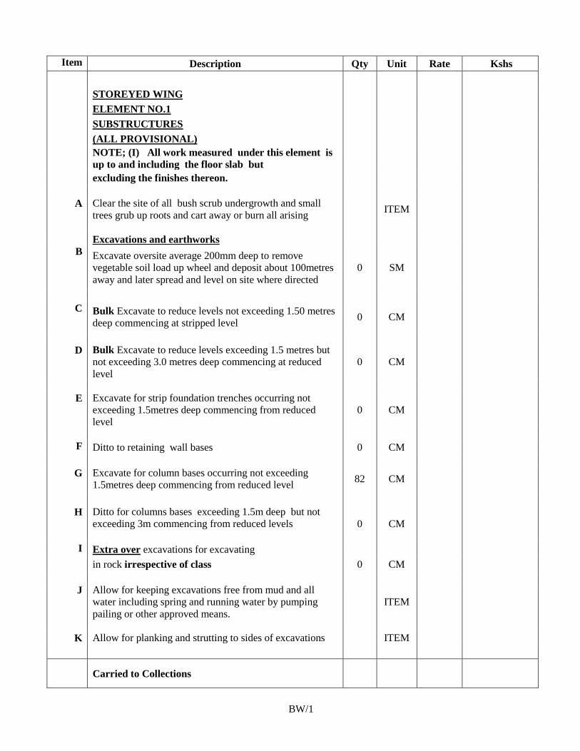
176
Item Description Qty Unit Rate Kshs
STOREYED WING
ELEMENT NO.1
SUBSTRUCTURES
(ALL PROVISIONAL)
NOTE; (I) All work measured under this element is
up to and including the floor slab but
excluding the finishes thereon.
A Clear the site of all bush scrub undergrowth and small
trees grub up roots and cart away or burn all arising ITEM
Excavations and earthworks
B Excavate oversite average 200mm deep to remove
vegetable soil load up wheel and deposit about 100metres
away and later spread and level on site where directed
0 SM
C Bulk Excavate to reduce levels not exceeding 1.50 metres
deep commencing at stripped level 0 CM
D Bulk Excavate to reduce levels exceeding 1.5 metres but
not exceeding 3.0 metres deep commencing at reduced
level
0 CM
E Excavate for strip foundation trenches occurring not
exceeding 1.5metres deep commencing from reduced
level
0 CM
F Ditto to retaining wall bases 0 CM
G Excavate for column bases occurring not exceeding
1.5metres deep commencing from reduced level 82 CM
H Ditto for columns bases exceeding 1.5m deep but not
exceeding 3m commencing from reduced levels 0 CM
I Extra over excavations for excavating
in rock irrespective of class 0 CM
J Allow for keeping excavations free from mud and all
water including spring and running water by pumping
pailing or other approved means.
ITEM
K Allow for planking and strutting to sides of excavations ITEM
Carried to Collections
BW/1
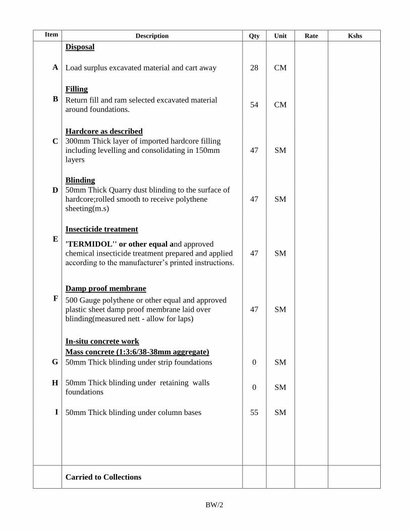
177
Item Description Qty Unit Rate Kshs
Disposal
A Load surplus excavated material and cart away 28 CM
Filling
B Return fill and ram selected excavated material
around foundations. 54 CM
Hardcore as described
C 300mm Thick layer of imported hardcore filling
including levelling and consolidating in 150mm
layers
47 SM
Blinding
D 50mm Thick Quarry dust blinding to the surface of
hardcore;rolled smooth to receive polythene
sheeting(m.s)
47 SM
Insecticide treatment
E 'TERMIDOL'' or other equal and approved
chemical insecticide treatment prepared and applied
according to the manufacturer’s printed instructions.
47 SM
Damp proof membrane
F 500 Gauge polythene or other equal and approved
plastic sheet damp proof membrane laid over
blinding(measured nett - allow for laps)
47 SM
In-situ concrete work
Mass concrete (1:3:6/38-38mm aggregate)
G 50mm Thick blinding under strip foundations 0 SM
H 50mm Thick blinding under retaining walls
foundations 0 SM
I 50mm Thick blinding under column bases 55 SM
Carried to Collections
BW/2
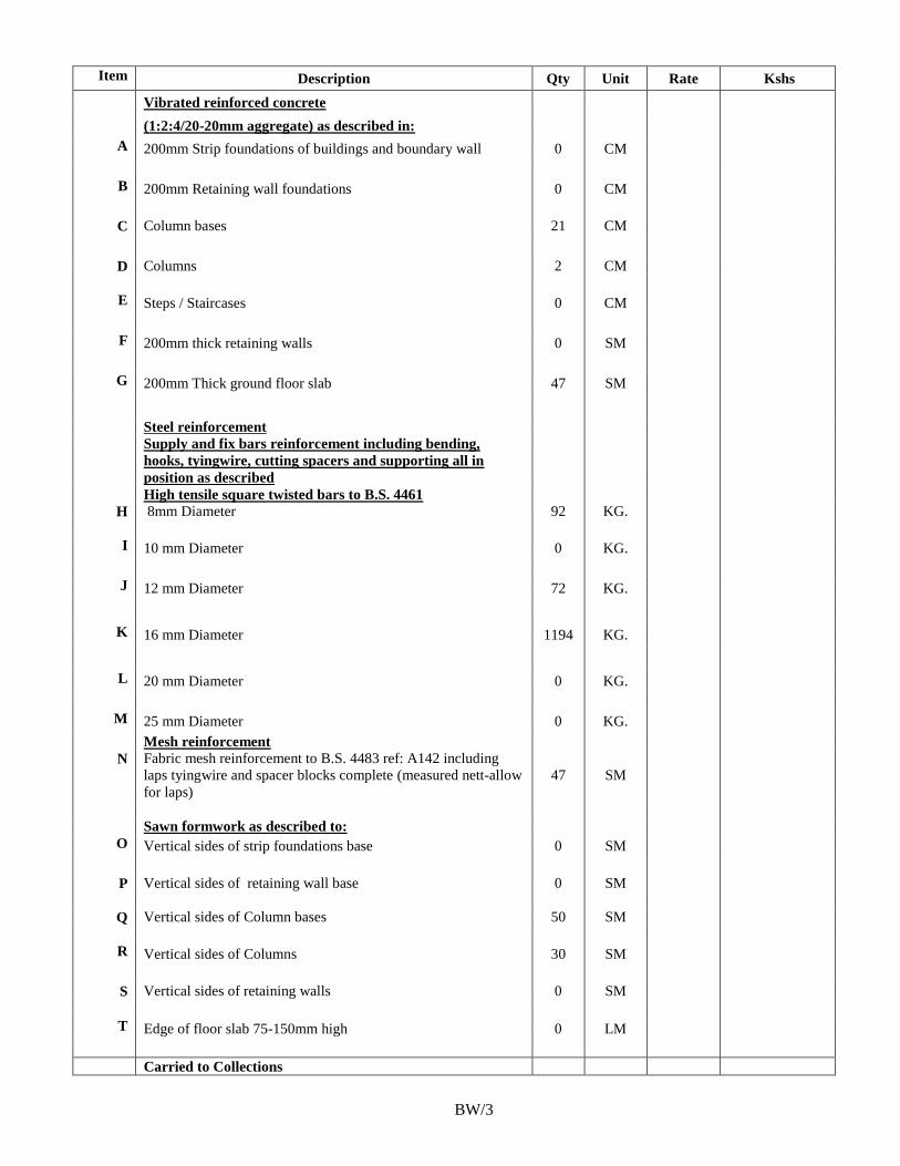
178
Item Description Qty Unit Rate Kshs
Vibrated reinforced concrete
(1:2:4/20-20mm aggregate) as described in:
A 200mm Strip foundations of buildings and boundary wall 0 CM
B 200mm Retaining wall foundations 0 CM
C Column bases 21 CM
D Columns 2 CM
E Steps / Staircases 0 CM
F 200mm thick retaining walls 0 SM
G 200mm Thick ground floor slab 47 SM
Steel reinforcement
Supply and fix bars reinforcement including bending,
hooks, tyingwire, cutting spacers and supporting all in
position as described
High tensile square twisted bars to B.S. 4461
H 8mm Diameter 92 KG.
I 10 mm Diameter 0 KG.
J 12 mm Diameter 72 KG.
K 16 mm Diameter 1194 KG.
L 20 mm Diameter 0 KG.
M 25 mm Diameter 0 KG.
Mesh reinforcement
N Fabric mesh reinforcement to B.S. 4483 ref: A142 including
laps tyingwire and spacer blocks complete (measured nett-allow
for laps)
47 SM
Sawn formwork as described to:
O Vertical sides of strip foundations base 0 SM
P Vertical sides of retaining wall base 0 SM
Q Vertical sides of Column bases 50 SM
R Vertical sides of Columns 30 SM
S Vertical sides of retaining walls 0 SM
T Edge of floor slab 75-150mm high 0 LM
Carried to Collections
BW/3
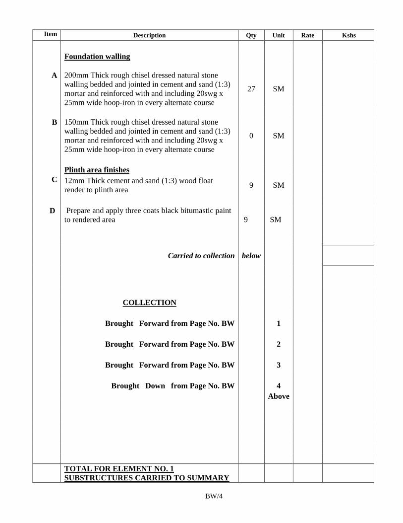
179
Item Description Qty Unit Rate Kshs
Foundation walling
A 200mm Thick rough chisel dressed natural stone
walling bedded and jointed in cement and sand (1:3)
mortar and reinforced with and including 20swg x
25mm wide hoop-iron in every alternate course
27 SM
B 150mm Thick rough chisel dressed natural stone
walling bedded and jointed in cement and sand (1:3)
mortar and reinforced with and including 20swg x
25mm wide hoop-iron in every alternate course
0 SM
Plinth area finishes
C 12mm Thick cement and sand (1:3) wood float
render to plinth area 9 SM
D Prepare and apply three coats black bitumastic paint
to rendered area 9 SM
Carried to collection below
COLLECTION
Brought Forward from Page No. BW 1
Brought Forward from Page No. BW 2
Brought Forward from Page No. BW 3
Brought Down from Page No. BW 4
Above
TOTAL FOR ELEMENT NO. 1
SUBSTRUCTURES CARRIED TO SUMMARY
BW/4
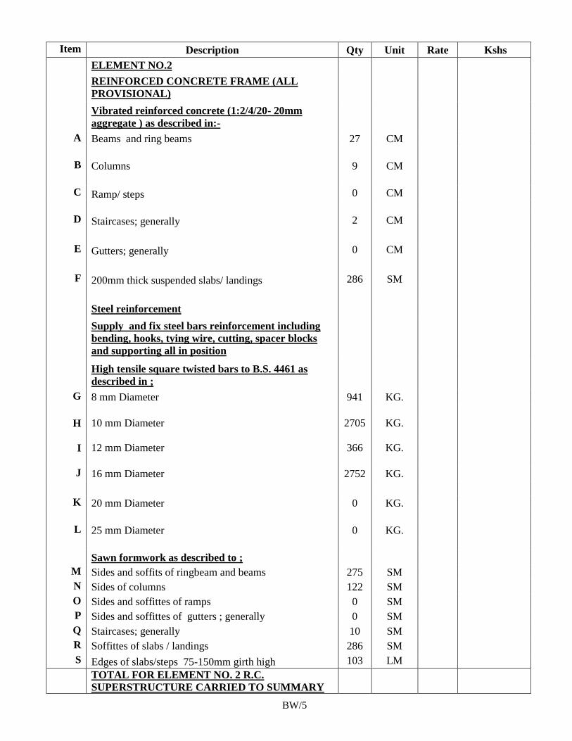
180
Item Description Qty Unit Rate Kshs
ELEMENT NO.2
REINFORCED CONCRETE FRAME (ALL
PROVISIONAL)
Vibrated reinforced concrete (1:2/4/20- 20mm
aggregate ) as described in:-
A Beams and ring beams 27 CM
B Columns 9 CM
C Ramp/ steps 0 CM
D Staircases; generally 2 CM
E Gutters; generally 0 CM
F 200mm thick suspended slabs/ landings 286 SM
Steel reinforcement
Supply and fix steel bars reinforcement including
bending, hooks, tying wire, cutting, spacer blocks
and supporting all in position
High tensile square twisted bars to B.S. 4461 as
described in ;
G 8 mm Diameter 941 KG.
H 10 mm Diameter 2705 KG.
I 12 mm Diameter 366 KG.
J 16 mm Diameter 2752 KG.
K 20 mm Diameter 0 KG.
L 25 mm Diameter 0 KG.
Sawn formwork as described to ;
M Sides and soffits of ringbeam and beams 275 SM
N Sides of columns 122 SM
O Sides and soffittes of ramps 0 SM
P Sides and soffittes of gutters ; generally 0 SM
Q Staircases; generally 10 SM
R Soffittes of slabs / landings 286 SM
S Edges of slabs/steps 75-150mm girth high 103 LM
TOTAL FOR ELEMENT NO. 2 R.C.
SUPERSTRUCTURE CARRIED TO SUMMARY
BW/5
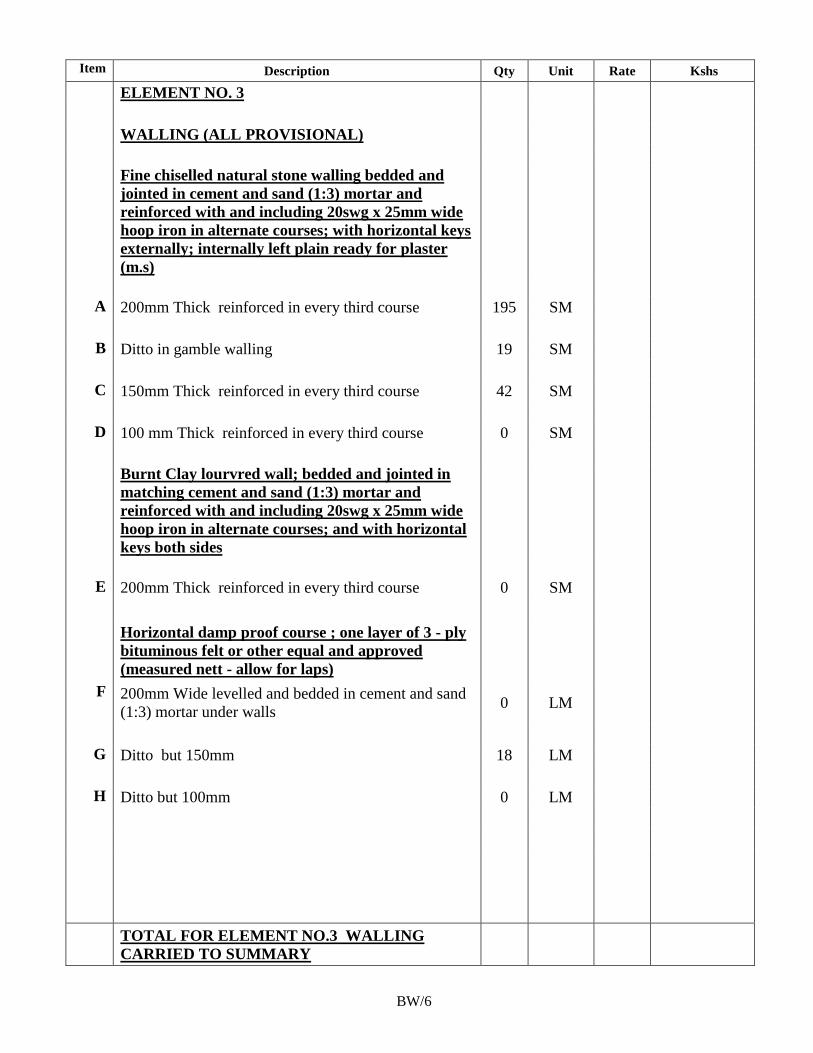
181
Item Description Qty Unit Rate Kshs
ELEMENT NO. 3
WALLING (ALL PROVISIONAL)
Fine chiselled natural stone walling bedded and
jointed in cement and sand (1:3) mortar and
reinforced with and including 20swg x 25mm wide
hoop iron in alternate courses; with horizontal keys
externally; internally left plain ready for plaster
(m.s)
A 200mm Thick reinforced in every third course 195 SM
B Ditto in gamble walling 19 SM
C 150mm Thick reinforced in every third course 42 SM
D 100 mm Thick reinforced in every third course 0 SM
Burnt Clay lourvred wall; bedded and jointed in
matching cement and sand (1:3) mortar and
reinforced with and including 20swg x 25mm wide
hoop iron in alternate courses; and with horizontal
keys both sides
E 200mm Thick reinforced in every third course 0 SM
Horizontal damp proof course ; one layer of 3 - ply
bituminous felt or other equal and approved
(measured nett - allow for laps)
F 200mm Wide levelled and bedded in cement and sand
(1:3) mortar under walls 0 LM
G Ditto but 150mm 18 LM
H Ditto but 100mm 0 LM
TOTAL FOR ELEMENT NO.3 WALLING
CARRIED TO SUMMARY
BW/6
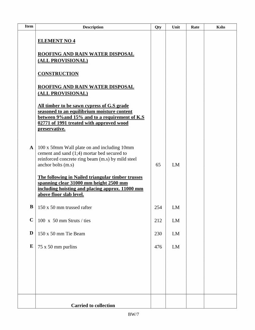
182
Item Description Qty Unit Rate Kshs
ELEMENT NO 4
ROOFING AND RAIN WATER DISPOSAL
(ALL PROVISIONAL)
CONSTRUCTION
ROOFING AND RAIN WATER DISPOSAL
(ALL PROVISIONAL)
All timber to be sawn cypress of G.S grade
seasoned to an equilibrium moisture content
between 9%and 15% and to a requirement of K.S
02771 of 1991 treated with approved wood
preservative.
A 100 x 50mm Wall plate on and including 10mm
cement and sand (1;4) mortar bed secured to
reinforced concrete ring beam (m.s) by mild steel
anchor bolts (m.s) 65 LM
The following in Nailed triangular timber trusses
spanning clear 31000 mm height 2500 mm
including hoisting and placing approx. 11000 mm
above floor slab level.
B 150 x 50 mm trussed rafter 254 LM
C 100 x 50 mm Struts / ties 212 LM
D 150 x 50 mm Tie Beam 230 LM
E 75 x 50 mm purlins 476 LM
Carried to collection
BW/7
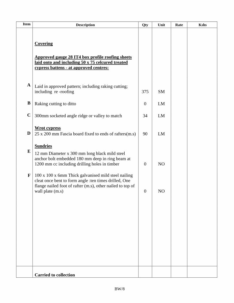
183
Item Description Qty Unit Rate Kshs
Covering
Approved gauge 28 IT4 box profile roofing sheets
laid onto and including 50 x 75 celcured treated
cypress battens - at approved centres:
A Laid in approved pattern; including raking cutting;
including re -roofing 375 SM
B Raking cutting to ditto 0 LM
C 300mm socketed angle ridge or valley to match 34 LM
Wrot cypress
D 25 x 200 mm Fascia board fixed to ends of rafters(m.s) 90 LM
Sundries
E 12 mm Diameter x 300 mm long black mild steel
anchor bolt embedded 180 mm deep in ring beam at
1200 mm cc including drilling holes in timber 0 NO
F 100 x 100 x 6mm Thick galvanised mild steel nailing
cleat once bent to form angle :ten times drilled, One
flange nailed foot of rafter (m.s), other nailed to top of
wall plate (m.s) 0 NO
Carried to collection
BW/8
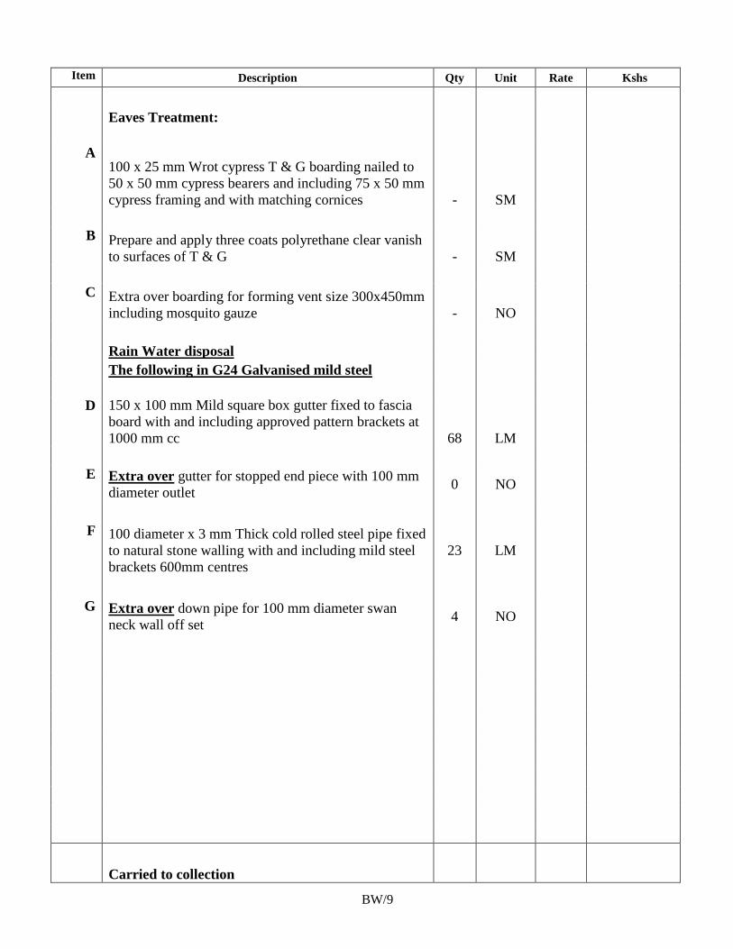
184
Item Description Qty Unit Rate Kshs
Eaves Treatment:
A 100 x 25 mm Wrot cypress T & G boarding nailed to
50 x 50 mm cypress bearers and including 75 x 50 mm
cypress framing and with matching cornices
- SM
B Prepare and apply three coats polyrethane clear vanish
to surfaces of T & G - SM
C Extra over boarding for forming vent size 300x450mm
including mosquito gauze - NO
Rain Water disposal
The following in G24 Galvanised mild steel
D 150 x 100 mm Mild square box gutter fixed to fascia
board with and including approved pattern brackets at
1000 mm cc 68 LM
E Extra over gutter for stopped end piece with 100 mm
diameter outlet 0 NO
F 100 diameter x 3 mm Thick cold rolled steel pipe fixed
to natural stone walling with and including mild steel
brackets 600mm centres
23 LM
G Extra over down pipe for 100 mm diameter swan
neck wall off set 4 NO
Carried to collection
BW/9
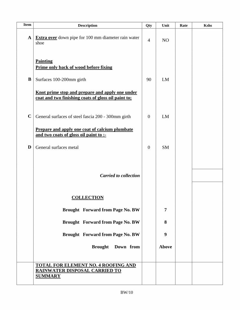
185
Item Description Qty Unit Rate Kshs
A Extra over down pipe for 100 mm diameter rain water
shoe 4 NO
Painting
Prime only back of wood before fixing
B Surfaces 100-200mm girth 90 LM
Knot prime stop and prepare and apply one under
coat and two finishing coats of gloss oil paint to;
C General surfaces of steel fascia 200 - 300mm girth 0 LM
Prepare and apply one coat of calcium plumbate
and two coats of gloss oil paint to :-
D General surfaces metal 0 SM
Carried to collection
COLLECTION
Brought Forward from Page No. BW 7
Brought Forward from Page No. BW 8
Brought Forward from Page No. BW 9
Brought Down from Above
TOTAL FOR ELEMENT NO. 4 ROOFING AND
RAINWATER DISPOSAL CARRIED TO
SUMMARY
BW/10
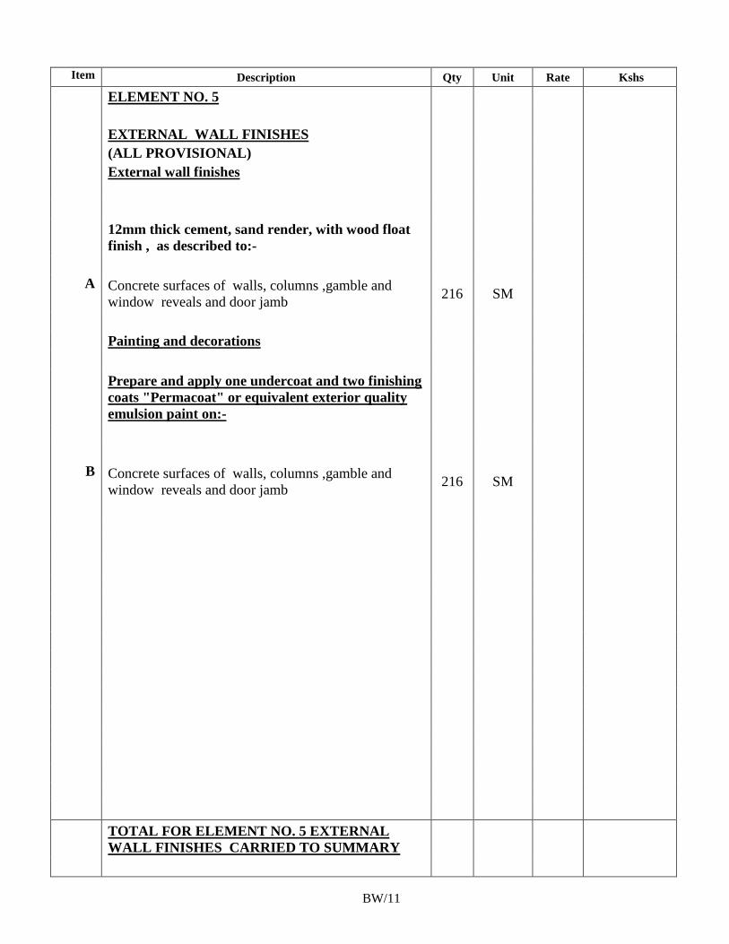
186
Item Description Qty Unit Rate Kshs
ELEMENT NO. 5
EXTERNAL WALL FINISHES
(ALL PROVISIONAL)
External wall finishes
12mm thick cement, sand render, with wood float
finish , as described to:-
A Concrete surfaces of walls, columns ,gamble and
window reveals and door jamb 216 SM
Painting and decorations
Prepare and apply one undercoat and two finishing
coats "Permacoat" or equivalent exterior quality
emulsion paint on:-
B Concrete surfaces of walls, columns ,gamble and
window reveals and door jamb 216 SM
TOTAL FOR ELEMENT NO. 5 EXTERNAL
WALL FINISHES CARRIED TO SUMMARY
BW/11
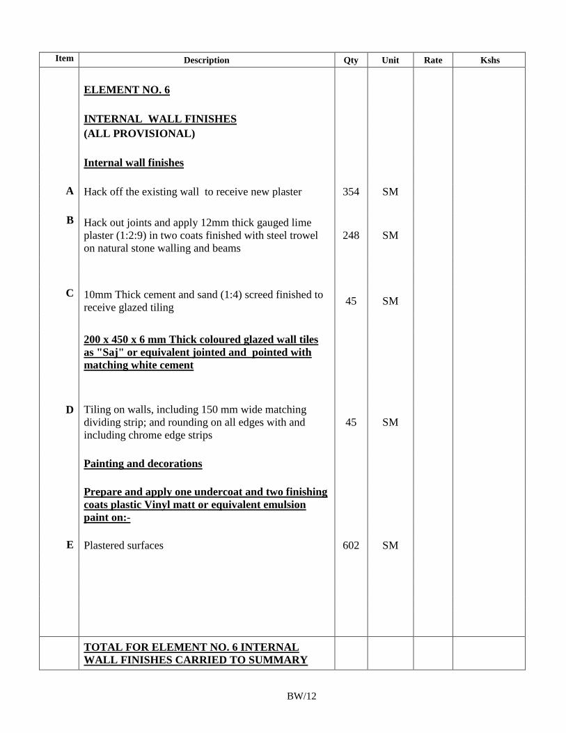
187
Item Description Qty Unit Rate Kshs
ELEMENT NO. 6
INTERNAL WALL FINISHES
(ALL PROVISIONAL)
Internal wall finishes
A Hack off the existing wall to receive new plaster 354 SM
B Hack out joints and apply 12mm thick gauged lime
plaster (1:2:9) in two coats finished with steel trowel
on natural stone walling and beams
248 SM
C 10mm Thick cement and sand (1:4) screed finished to
receive glazed tiling 45 SM
200 x 450 x 6 mm Thick coloured glazed wall tiles
as "Saj" or equivalent jointed and pointed with
matching white cement
D Tiling on walls, including 150 mm wide matching
dividing strip; and rounding on all edges with and
including chrome edge strips
45 SM
Painting and decorations
Prepare and apply one undercoat and two finishing
coats plastic Vinyl matt or equivalent emulsion
paint on:-
E Plastered surfaces 602 SM
TOTAL FOR ELEMENT NO. 6 INTERNAL
WALL FINISHES CARRIED TO SUMMARY
BW/12
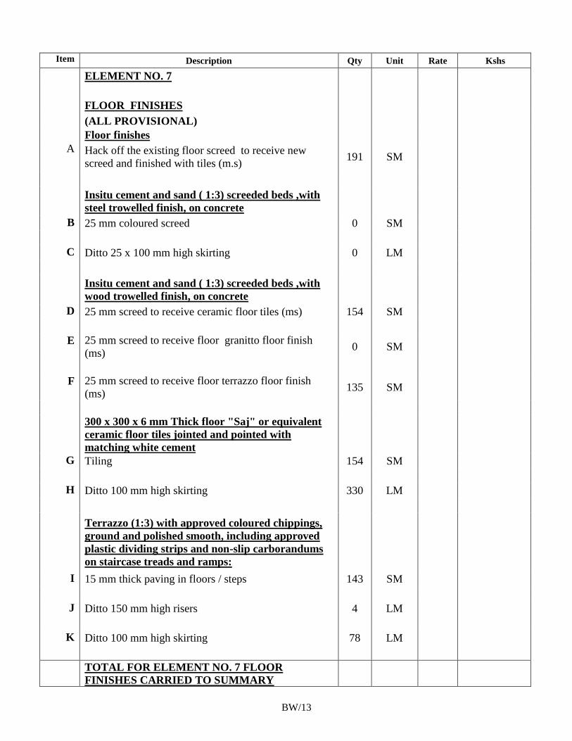
188
Item Description Qty Unit Rate Kshs
ELEMENT NO. 7
FLOOR FINISHES
(ALL PROVISIONAL)
Floor finishes
A Hack off the existing floor screed to receive new
screed and finished with tiles (m.s) 191 SM
Insitu cement and sand ( 1:3) screeded beds ,with
steel trowelled finish, on concrete
B 25 mm coloured screed 0 SM
C Ditto 25 x 100 mm high skirting 0 LM
Insitu cement and sand ( 1:3) screeded beds ,with
wood trowelled finish, on concrete
D 25 mm screed to receive ceramic floor tiles (ms) 154 SM
E 25 mm screed to receive floor granitto floor finish
(ms) 0 SM
F 25 mm screed to receive floor terrazzo floor finish
(ms) 135 SM
300 x 300 x 6 mm Thick floor "Saj" or equivalent
ceramic floor tiles jointed and pointed with
matching white cement
G Tiling 154 SM
H Ditto 100 mm high skirting 330 LM
Terrazzo (1:3) with approved coloured chippings,
ground and polished smooth, including approved
plastic dividing strips and non-slip carborandums
on staircase treads and ramps:
I 15 mm thick paving in floors / steps 143 SM
J Ditto 150 mm high risers 4 LM
K Ditto 100 mm high skirting 78 LM
TOTAL FOR ELEMENT NO. 7 FLOOR
FINISHES CARRIED TO SUMMARY
BW/13
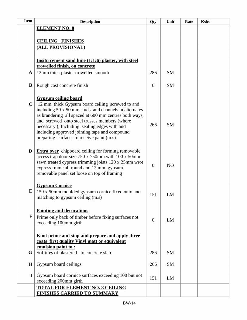
189
Item Description Qty Unit Rate Kshs
ELEMENT NO. 8
CEILING FINISHES
(ALL PROVISIONAL)
Insitu cement sand lime (1:1:6) plaster, with steel
trowelled finish, on concrete
A 12mm thick plaster trowelled smooth 286 SM
B Rough cast concrete finish 0 SM
Gypsum ceiling board
C 12 mm thick Gypsum board ceiling screwed to and
including 50 x 50 mm studs and channels in alternates
as brandering all spaced at 600 mm centres both ways,
and screwed onto steel trusses members (where
necessary ); Including sealing edges with and
including approved jointing tape and compound
preparing surfaces to receive paint (m.s)
266 SM
D Extra over chipboard ceiling for forming removable
access trap door size 750 x 750mm with 100 x 50mm
sawn treated cypress trimming joists 120 x 25mm wrot
cypress frame all round and 12 mm gypsum
removable panel set loose on top of framing
0 NO
Gypsum Cornice
E 150 x 50mm moulded gypsum cornice fixed onto and
matching to gypsum ceiling (m.s) 151 LM
Painting and decorations
F Prime only back of timber before fixing surfaces not
exceeding 100mm girth 0 LM
Knot prime and stop and prepare and apply three
coats first quality Vinyl matt or equivalent
emulsion paint to :
G Soffittes of plastered to concrete slab 286 SM
H Gypsum board ceilings 266 SM
I Gypsum board cornice surfaces exceeding 100 but not
exceeding 200mm girth 151 LM
TOTAL FOR ELEMENT NO. 8 CEILING
FINISHES CARRIED TO SUMMARY
BW/14
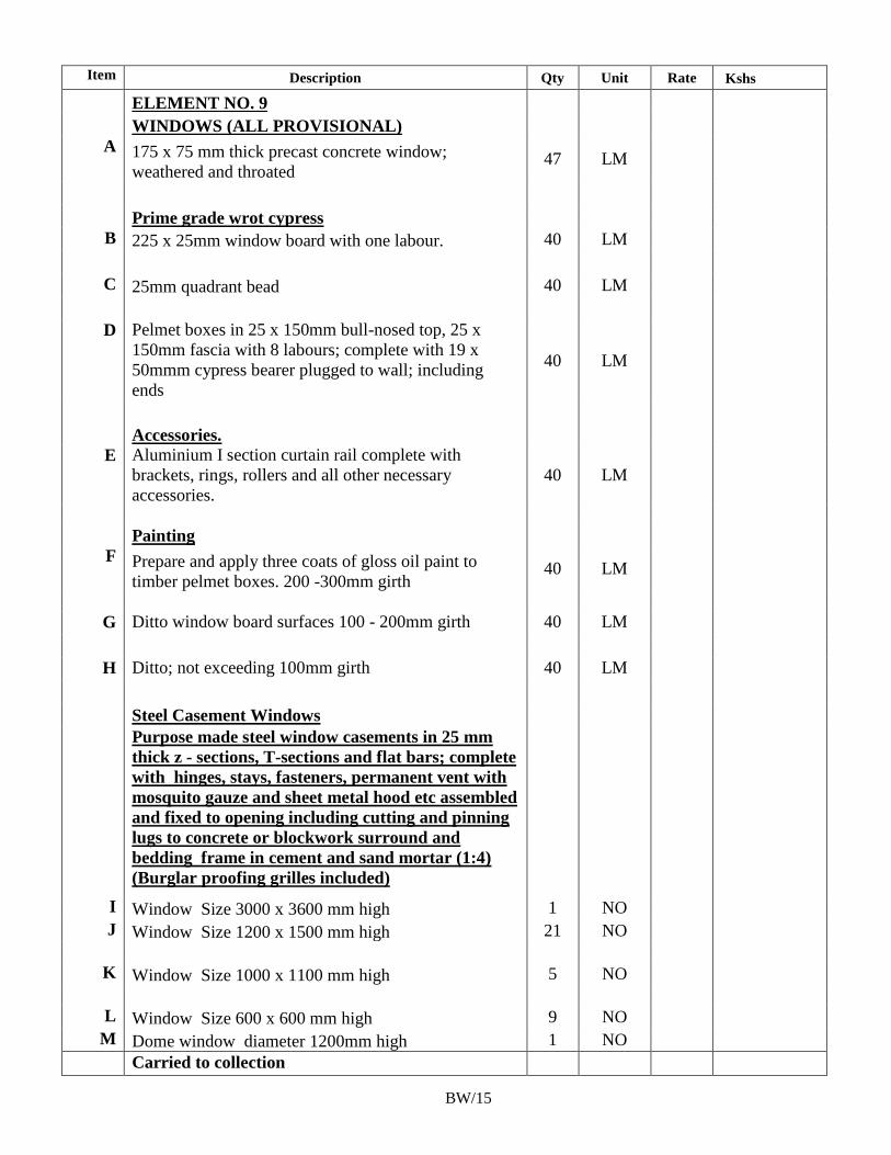
190
Item Description Qty Unit Rate Kshs
ELEMENT NO. 9
WINDOWS (ALL PROVISIONAL)
A 175 x 75 mm thick precast concrete window;
weathered and throated 47 LM
Prime grade wrot cypress
B 225 x 25mm window board with one labour. 40 LM
C 25mm quadrant bead 40 LM
D Pelmet boxes in 25 x 150mm bull-nosed top, 25 x
150mm fascia with 8 labours; complete with 19 x
50mmm cypress bearer plugged to wall; including
ends
40 LM
Accessories.
E Aluminium I section curtain rail complete with
brackets, rings, rollers and all other necessary
accessories.
40 LM
Painting
F Prepare and apply three coats of gloss oil paint to
timber pelmet boxes. 200 -300mm girth 40 LM
G Ditto window board surfaces 100 - 200mm girth 40 LM
H Ditto; not exceeding 100mm girth 40 LM
Steel Casement Windows
Purpose made steel window casements in 25 mm
thick z - sections, T-sections and flat bars; complete
with hinges, stays, fasteners, permanent vent with
mosquito gauze and sheet metal hood etc assembled
and fixed to opening including cutting and pinning
lugs to concrete or blockwork surround and
bedding frame in cement and sand mortar (1:4)
(Burglar proofing grilles included)
I Window Size 3000 x 3600 mm high 1 NO
J Window Size 1200 x 1500 mm high 21 NO
K Window Size 1000 x 1100 mm high 5 NO
L Window Size 600 x 600 mm high 9 NO
M Dome window diameter 1200mm high 1 NO
Carried to collection
BW/15
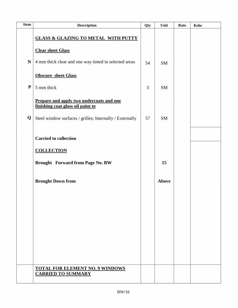
191
Item Description Qty Unit Rate Kshs
GLASS & GLAZING TO METAL WITH PUTTY
Clear sheet Glass
N 4 mm thick clear and one way tinted in selected areas 54 SM
Obscure sheet Glass
P 5 mm thick 3 SM
Prepare and apply two undercoats and one
finishing coat gloss oil paint to
Q Steel window surfaces / grilles; Internally / Externally 57 SM
Carried to collection
COLLECTION
Brought Forward from Page No. BW 15
Brought Down from Above
TOTAL FOR ELEMENT NO. 9 WINDOWS
CARRIED TO SUMMARY
BW/16
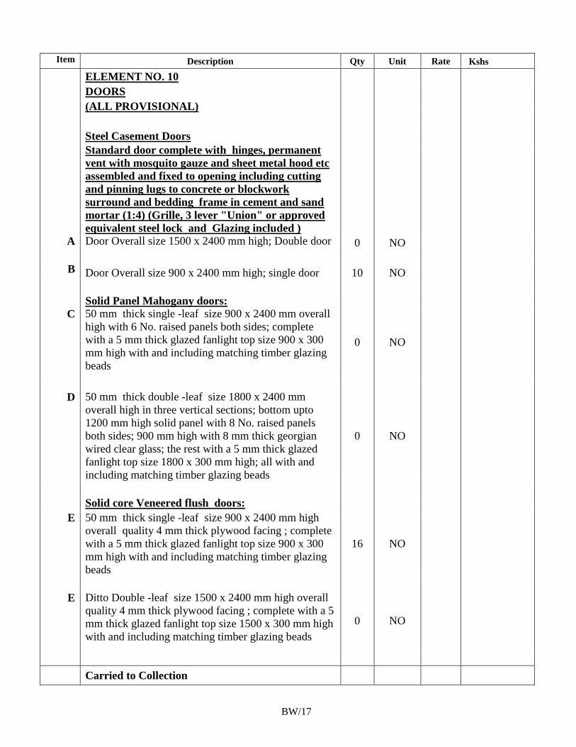
192
Item Description Qty Unit Rate Kshs
ELEMENT NO. 10
DOORS
(ALL PROVISIONAL)
Steel Casement Doors
Standard door complete with hinges, permanent
vent with mosquito gauze and sheet metal hood etc
assembled and fixed to opening including cutting
and pinning lugs to concrete or blockwork
surround and bedding frame in cement and sand
mortar (1:4) (Grille, 3 lever "Union" or approved
equivalent steel lock and Glazing included )
A Door Overall size 1500 x 2400 mm high; Double door 0 NO
B Door Overall size 900 x 2400 mm high; single door 10 NO
Solid Panel Mahogany doors:
C 50 mm thick single -leaf size 900 x 2400 mm overall
high with 6 No. raised panels both sides; complete
with a 5 mm thick glazed fanlight top size 900 x 300
mm high with and including matching timber glazing
beads
0 NO
D 50 mm thick double -leaf size 1800 x 2400 mm
overall high in three vertical sections; bottom upto
1200 mm high solid panel with 8 No. raised panels
both sides; 900 mm high with 8 mm thick georgian
wired clear glass; the rest with a 5 mm thick glazed
fanlight top size 1800 x 300 mm high; all with and
including matching timber glazing beads
0 NO
Solid core Veneered flush doors:
E 50 mm thick single -leaf size 900 x 2400 mm high
overall quality 4 mm thick plywood facing ; complete
with a 5 mm thick glazed fanlight top size 900 x 300
mm high with and including matching timber glazing
beads
16 NO
E Ditto Double -leaf size 1500 x 2400 mm high overall
quality 4 mm thick plywood facing ; complete with a 5
mm thick glazed fanlight top size 1500 x 300 mm high
with and including matching timber glazing beads
0 NO
Carried to Collection
BW/17
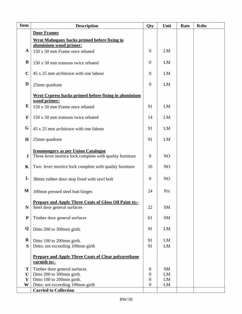
193
Item Description Qty Unit Rate Kshs
Door Frames
Wrot Mahogany backs primed before fixing in
aluminium wood primer:
A 150 x 50 mm Frame once rebated 0 LM
B 150 x 50 mm transom twice rebated 0 LM
C 45 x 25 mm architrave with one labour 0 LM
D 25mm quadrant 0 LM
Wrot Cypress backs primed before fixing in aluminium
wood primer:
E 150 x 50 mm Frame once rebated 91 LM
F 150 x 50 mm transom twice rebated 14 LM
G 45 x 25 mm architrave with one labour 91 LM
H 25mm quadrant 91 LM
Ironmongery as per Union Catalogue
J Three lever mortice lock complete with quality furniture 0 NO
K Two lever mortice lock complete with quality furniture 16 NO
L 38mm rubber door stop fixed with rawl bolt 0 NO
M 100mm pressed steel butt hinges 24 Prs
Prepare and Apply Three Coats of Gloss Oil Paint to:-
N Steel door general surfaces 22 SM
P Timber door general surfaces 61 SM
Q Ditto 200 to 300mm girth. 91 LM
R Ditto 100 to 200mm girth. 91 LM
S Ditto; not exceeding 100mm girth 91 LM
Prepare and Apply Three Coats of Clear polyurethane
varnish to:-
T Timber door general surfaces 0 SM
U Ditto 200 to 300mm girth. 0 LM
V Ditto 100 to 200mm girth. 0 LM
W Ditto; not exceeding 100mm girth 0 LM
Carried to Collection
BW/18
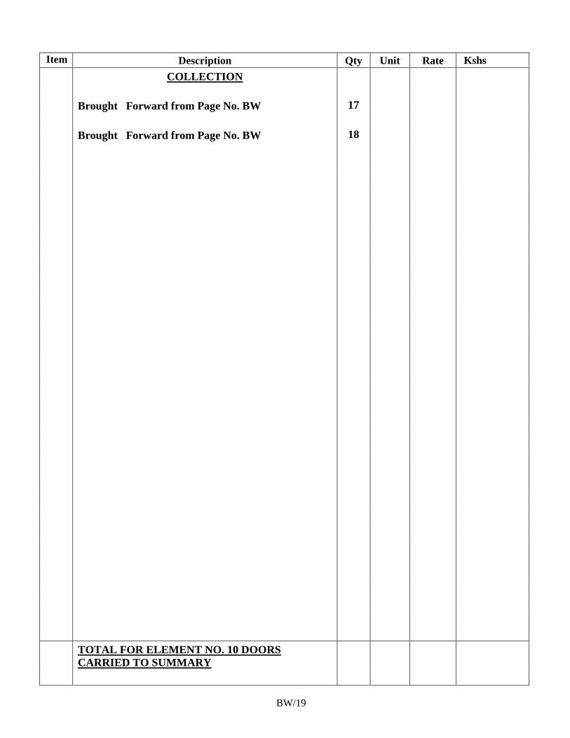
194
Item Description Qty Unit Rate Kshs
COLLECTION
Brought Forward from Page No. BW 17
Brought Forward from Page No. BW 18
TOTAL FOR ELEMENT NO. 10 DOORS
CARRIED TO SUMMARY
BW/19
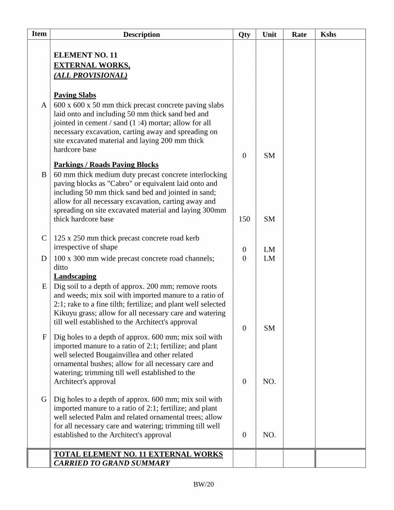
195
Item Description Qty Unit Rate Kshs
ELEMENT NO. 11
EXTERNAL WORKS,
(ALL PROVISIONAL)
Paving Slabs
A 600 x 600 x 50 mm thick precast concrete paving slabs
laid onto and including 50 mm thick sand bed and
jointed in cement / sand (1 :4) mortar; allow for all
necessary excavation, carting away and spreading on
site excavated material and laying 200 mm thick
hardcore base 0 SM
Parkings / Roads Paving Blocks
B 60 mm thick medium duty precast concrete interlocking
paving blocks as "Cabro" or equivalent laid onto and
including 50 mm thick sand bed and jointed in sand;
allow for all necessary excavation, carting away and
spreading on site excavated material and laying 300mm
thick hardcore base 150 SM
C 125 x 250 mm thick precast concrete road kerb
irrespective of shape 0 LM
D 100 x 300 mm wide precast concrete road channels;
ditto
0 LM
Landscaping
E Dig soil to a depth of approx. 200 mm; remove roots
and weeds; mix soil with imported manure to a ratio of
2:1; rake to a fine tilth; fertilize; and plant well selected
Kikuyu grass; allow for all necessary care and watering
till well established to the Architect's approval 0 SM
F Dig holes to a depth of approx. 600 mm; mix soil with
imported manure to a ratio of 2:1; fertilize; and plant
well selected Bougainvillea and other related
ornamental bushes; allow for all necessary care and
watering; trimming till well established to the
Architect's approval 0 NO.
G Dig holes to a depth of approx. 600 mm; mix soil with
imported manure to a ratio of 2:1; fertilize; and plant
well selected Palm and related ornamental trees; allow
for all necessary care and watering; trimming till well
established to the Architect's approval 0 NO.
TOTAL ELEMENT NO. 11 EXTERNAL WORKS
CARRIED TO GRAND SUMMARY
BW/20
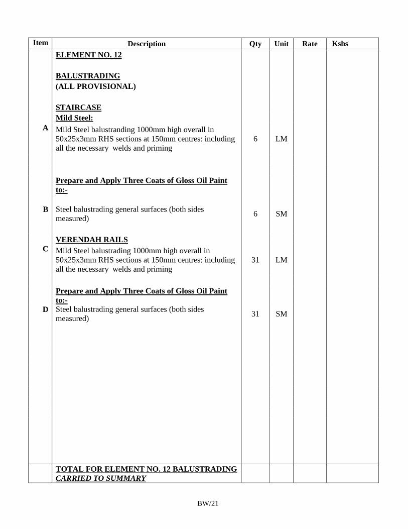
196
Item Description Qty Unit Rate Kshs
ELEMENT NO. 12
BALUSTRADING
(ALL PROVISIONAL)
STAIRCASE
Mild Steel:
A Mild Steel balustranding 1000mm high overall in
50x25x3mm RHS sections at 150mm centres: including
all the necessary welds and priming
6 LM
Prepare and Apply Three Coats of Gloss Oil Paint
to:-
B Steel balustrading general surfaces (both sides
measured) 6 SM
VERENDAH RAILS
C Mild Steel balustrading 1000mm high overall in
50x25x3mm RHS sections at 150mm centres: including
all the necessary welds and priming
31 LM
Prepare and Apply Three Coats of Gloss Oil Paint
to:-
D Steel balustrading general surfaces (both sides
measured) 31 SM
TOTAL FOR ELEMENT NO. 12 BALUSTRADING
CARRIED TO SUMMARY
BW/21
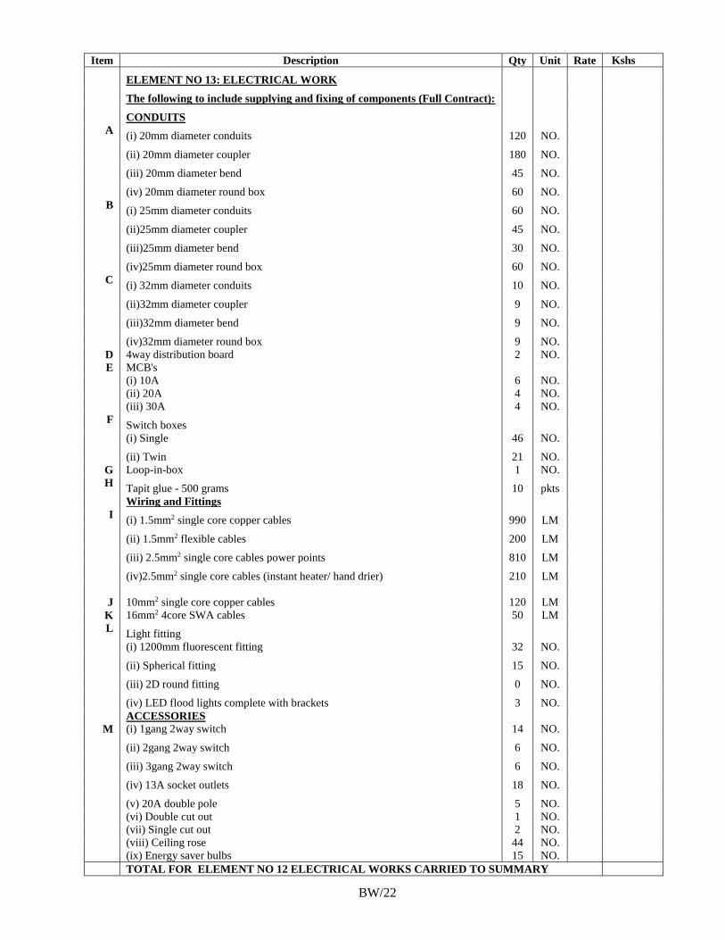
197
Item Description Qty Unit Rate Kshs
ELEMENT NO 13: ELECTRICAL WORK
The following to include supplying and fixing of components (Full Contract):
CONDUITS
A (i) 20mm diameter conduits 120 NO.
(ii) 20mm diameter coupler 180 NO.
(iii) 20mm diameter bend 45 NO.
(iv) 20mm diameter round box 60 NO.
B (i) 25mm diameter conduits 60 NO.
(ii)25mm diameter coupler 45 NO.
(iii)25mm diameter bend 30 NO.
(iv)25mm diameter round box 60 NO.
C (i) 32mm diameter conduits 10 NO.
(ii)32mm diameter coupler 9 NO.
(iii)32mm diameter bend 9 NO.
(iv)32mm diameter round box 9 NO.
D 4way distribution board 2 NO.
E MCB's
(i) 10A 6 NO.
(ii) 20A 4 NO.
(iii) 30A 4 NO.
F Switch boxes
(i) Single 46 NO.
(ii) Twin 21 NO.
G Loop-in-box 1 NO.
H Tapit glue - 500 grams 10 pkts
Wiring and Fittings
I (i) 1.5mm2 single core copper cables 990 LM
(ii) 1.5mm2 flexible cables 200 LM
(iii) 2.5mm2 single core cables power points 810 LM
(iv)2.5mm2 single core cables (instant heater/ hand drier) 210 LM
J 10mm2 single core copper cables 120 LM
K 16mm2 4core SWA cables 50 LM
L Light fitting
(i) 1200mm fluorescent fitting 32 NO.
(ii) Spherical fitting 15 NO.
(iii) 2D round fitting 0 NO.
(iv) LED flood lights complete with brackets 3 NO.
ACCESSORIES
M (i) 1gang 2way switch 14 NO.
(ii) 2gang 2way switch 6 NO.
(iii) 3gang 2way switch 6 NO.
(iv) 13A socket outlets 18 NO.
(v) 20A double pole 5 NO.
(vi) Double cut out 1 NO.
(vii) Single cut out 2 NO.
(viii) Ceiling rose 44 NO.
(ix) Energy saver bulbs 15 NO.
TOTAL FOR ELEMENT NO 12 ELECTRICAL WORKS CARRIED TO SUMMARY
BW/22
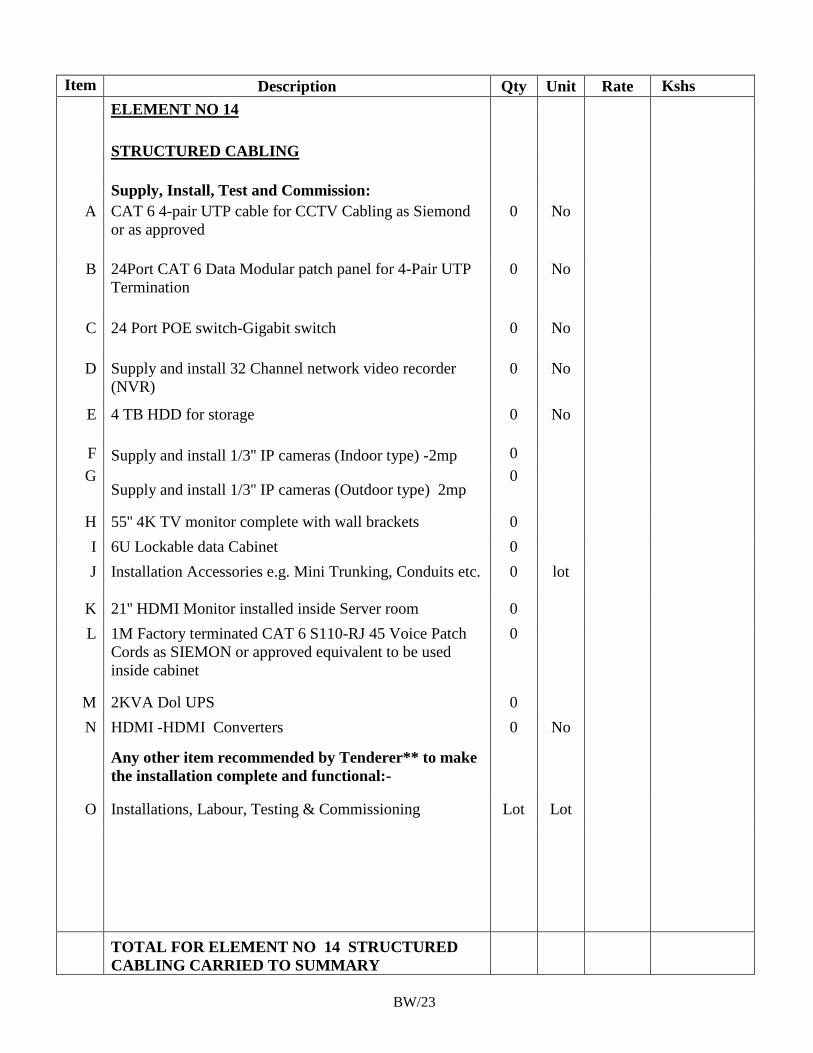
198
Item Description Qty Unit Rate Kshs
ELEMENT NO 14
STRUCTURED CABLING
Supply, Install, Test and Commission:
A CAT 6 4-pair UTP cable for CCTV Cabling as Siemond
or as approved
0 No
B 24Port CAT 6 Data Modular patch panel for 4-Pair UTP
Termination
0 No
C 24 Port POE switch-Gigabit switch 0 No
D Supply and install 32 Channel network video recorder
(NVR)
0 No
E 4 TB HDD for storage 0 No
F Supply and install 1/3'' IP cameras (Indoor type) -2mp 0
G Supply and install 1/3'' IP cameras (Outdoor type) 2mp
0
H 55'' 4K TV monitor complete with wall brackets 0
I 6U Lockable data Cabinet 0
J Installation Accessories e.g. Mini Trunking, Conduits etc. 0 lot
K 21'' HDMI Monitor installed inside Server room 0
L 1M Factory terminated CAT 6 S110-RJ 45 Voice Patch
Cords as SIEMON or approved equivalent to be used
inside cabinet
0
M 2KVA Dol UPS 0
N HDMI -HDMI Converters 0 No
Any other item recommended by Tenderer** to make
the installation complete and functional:-
O Installations, Labour, Testing & Commissioning Lot Lot
TOTAL FOR ELEMENT NO 14 STRUCTURED
CABLING CARRIED TO SUMMARY
BW/23
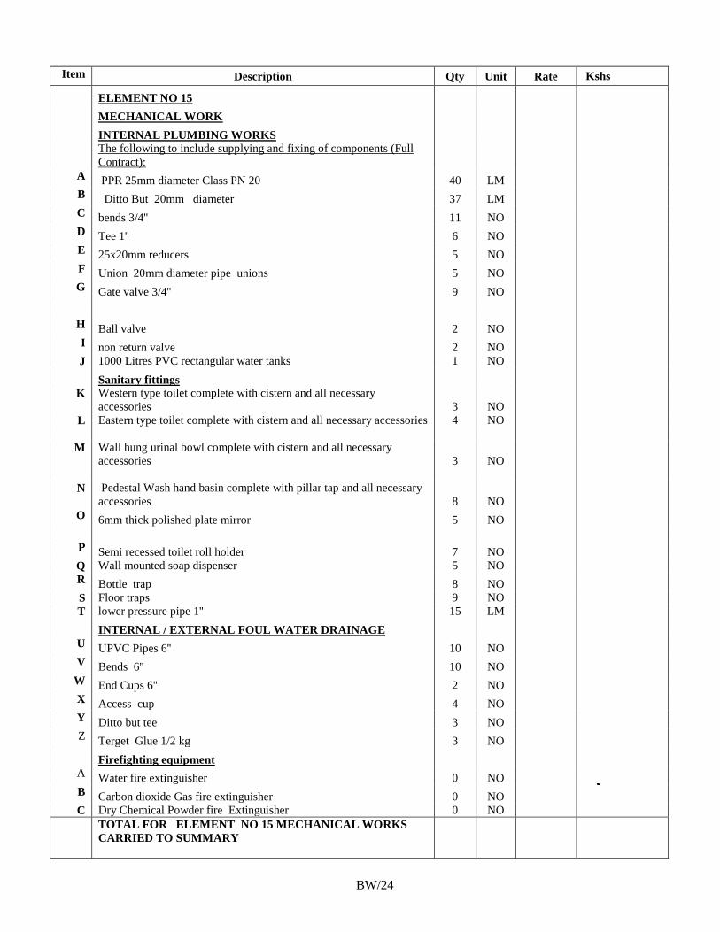
199
Item Description Qty Unit Rate Kshs
ELEMENT NO 15
MECHANICAL WORK
INTERNAL PLUMBING WORKS
The following to include supplying and fixing of components (Full
Contract):
A PPR 25mm diameter Class PN 20 40 LM
B Ditto But 20mm diameter 37 LM
C bends 3/4'' 11 NO
D Tee 1'' 6 NO
E 25x20mm reducers 5 NO
F Union 20mm diameter pipe unions 5 NO
G Gate valve 3/4'' 9 NO
H Ball valve 2 NO
I non return valve 2 NO
J 1000 Litres PVC rectangular water tanks 1 NO
Sanitary fittings
K Western type toilet complete with cistern and all necessary
accessories 3 NO
L Eastern type toilet complete with cistern and all necessary accessories 4 NO
M Wall hung urinal bowl complete with cistern and all necessary
accessories 3 NO
N Pedestal Wash hand basin complete with pillar tap and all necessary
accessories 8 NO
O 6mm thick polished plate mirror 5 NO
P Semi recessed toilet roll holder 7 NO
Q Wall mounted soap dispenser 5 NO
R Bottle trap 8 NO
S Floor traps 9 NO
T lower pressure pipe 1'' 15 LM
INTERNAL / EXTERNAL FOUL WATER DRAINAGE
U UPVC Pipes 6'' 10 NO
V Bends 6'' 10 NO
W End Cups 6'' 2 NO
X Access cup 4 NO
Y Ditto but tee 3 NO
Z Terget Glue 1/2 kg 3 NO
Firefighting equipment
A Water fire extinguisher 0 NO
B Carbon dioxide Gas fire extinguisher 0 NO
C Dry Chemical Powder fire Extinguisher 0 NO
TOTAL FOR ELEMENT NO 15 MECHANICAL WORKS
CARRIED TO SUMMARY
BW/24
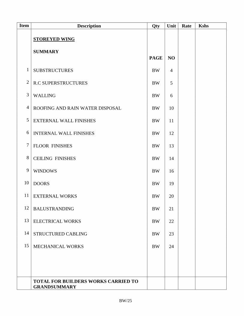
200
Item Description Qty Unit Rate Kshs
STOREYED WING
SUMMARY
PAGE NO
1 SUBSTRUCTURES BW 4
2 R.C SUPERSTRUCTURES BW 5
3 WALLING BW 6
4 ROOFING AND RAIN WATER DISPOSAL BW 10
5 EXTERNAL WALL FINISHES BW 11
6 INTERNAL WALL FINISHES BW 12
7 FLOOR FINISHES BW 13
8 CEILING FINISHES BW 14
9 WINDOWS BW 16
10 DOORS BW 19
11 EXTERNAL WORKS BW 20
12 BALUSTRANDING BW 21
13 ELECTRICAL WORKS BW 22
14 STRUCTURED CABLING BW 23
15 MECHANICAL WORKS BW 24
TOTAL FOR BUILDERS WORKS CARRIED TO
GRANDSUMMARY
BW/25
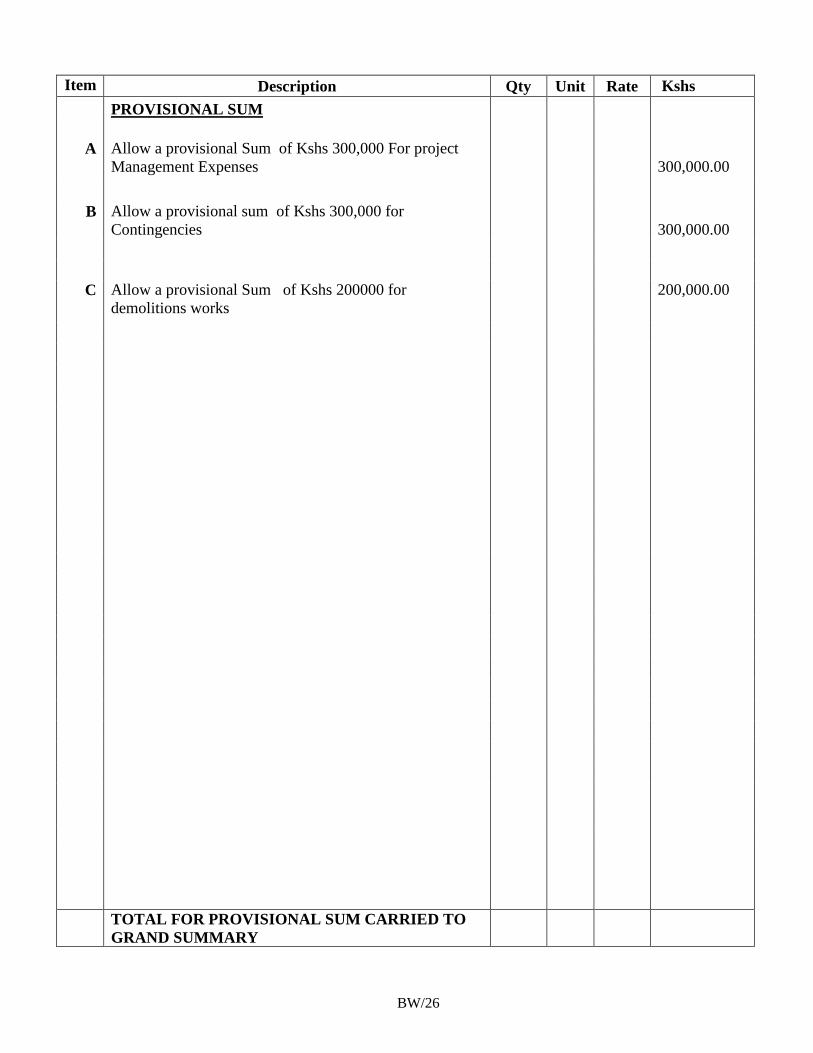
201
Item Description Qty Unit Rate Kshs
PROVISIONAL SUM
A Allow a provisional Sum of Kshs 300,000 For project
Management Expenses
300,000.00
B Allow a provisional sum of Kshs 300,000 for
Contingencies
300,000.00
C Allow a provisional Sum of Kshs 200000 for
demolitions works
200,000.00
TOTAL FOR PROVISIONAL SUM CARRIED TO
GRAND SUMMARY
BW/26
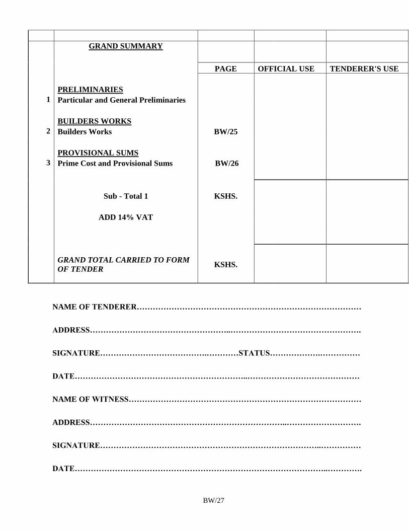
202
GRAND SUMMARY
PAGE OFFICIAL USE TENDERER'S USE
PRELIMINARIES
1 Particular and General Preliminaries
BUILDERS WORKS
2 Builders Works BW/25
PROVISIONAL SUMS
3 Prime Cost and Provisional Sums BW/26
Sub - Total 1 KSHS.
ADD 14% VAT
GRAND TOTAL CARRIED TO FORM
OF TENDER KSHS.
NAME OF TENDERER…………………………………………………………………………
ADDRESS……………………………………………..………………………………………….
SIGNATURE………………………………….…………STATUS……………….……………
DATE………………………………………………………..……………………………………
NAME OF WITNESS……………………………………………………………………………
ADDRESS………………………………………………………………..……………………….
SIGNATURE………………………………………………………………………..……………
DATE…………………………………………………………………………………..………….
BW/27
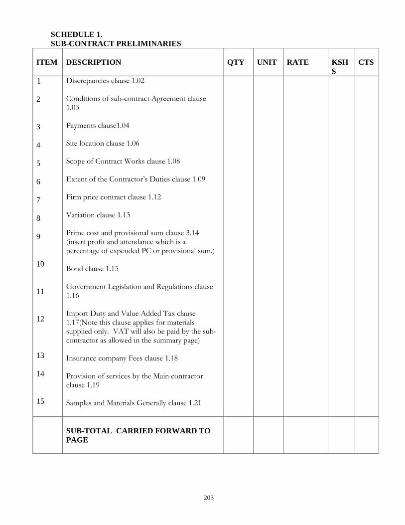
203
SCHEDULE 1.
SUB-CONTRACT PRELIMINARIES
ITEM
DESCRIPTION
QTY
UNIT
RATE
KSH
S
CTS
1
2
3
4
5
6
7
8
9
10
11
12
13
14
15
Discrepancies clause 1.02 Conditions of sub-contract Agreement clause 1.03 Payments clause1.04 Site location clause 1.06 Scope of Contract Works clause 1.08 Extent of the Contractor’s Duties clause 1.09 Firm price contract clause 1.12 Variation clause 1.13 Prime cost and provisional sum clause 3.14 (insert profit and attendance which is a percentage of expended PC or provisional sum.) Bond clause 1.15 Government Legislation and Regulations clause 1.16 Import Duty and Value Added Tax clause 1.17(Note this clause applies for materials supplied only. VAT will also be paid by the sub-contractor as allowed in the summary page) Insurance company Fees clause 1.18 Provision of services by the Main contractor clause 1.19 Samples and Materials Generally clause 1.21
SUB-TOTAL CARRIED FORWARD TO
PAGE
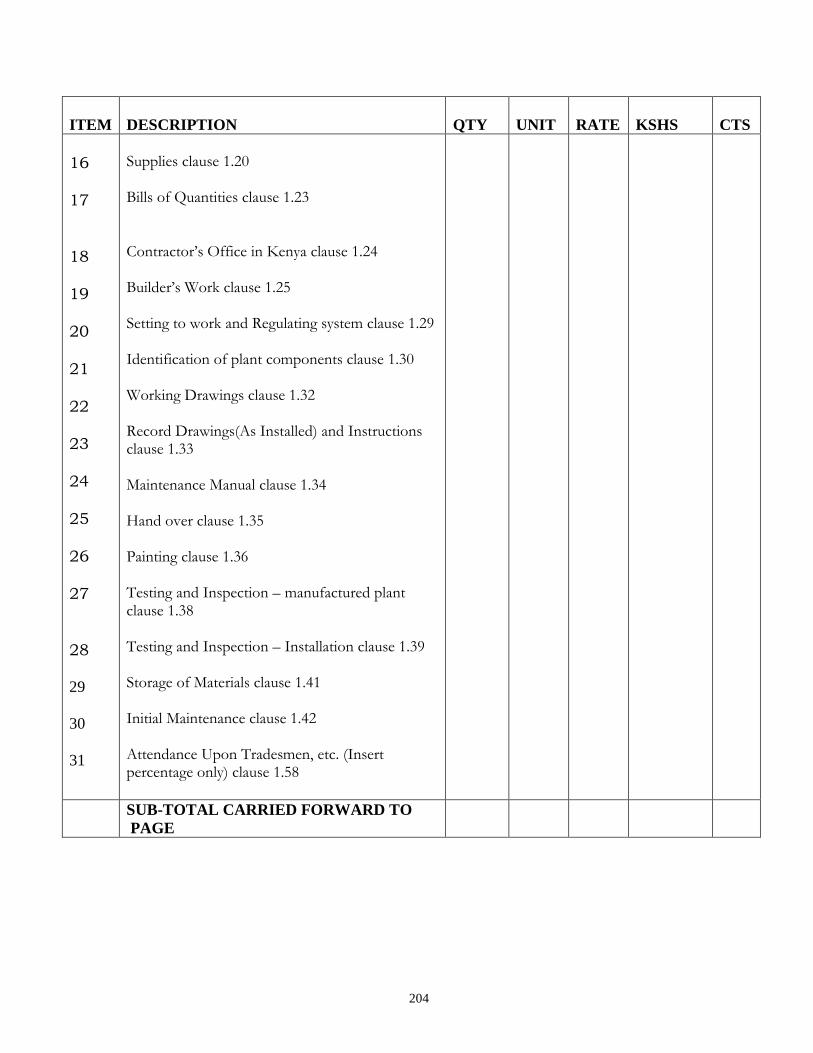
204
ITEM
DESCRIPTION
QTY
UNIT
RATE
KSHS
CTS
16 17
18 19
20
21
22 23
24
25
26 27
28 29
30
31
Supplies clause 1.20 Bills of Quantities clause 1.23
Contractor’s Office in Kenya clause 1.24 Builder’s Work clause 1.25 Setting to work and Regulating system clause 1.29 Identification of plant components clause 1.30 Working Drawings clause 1.32 Record Drawings(As Installed) and Instructions clause 1.33 Maintenance Manual clause 1.34 Hand over clause 1.35 Painting clause 1.36 Testing and Inspection – manufactured plant clause 1.38 Testing and Inspection – Installation clause 1.39 Storage of Materials clause 1.41 Initial Maintenance clause 1.42 Attendance Upon Tradesmen, etc. (Insert percentage only) clause 1.58
SUB-TOTAL CARRIED FORWARD TO
PAGE
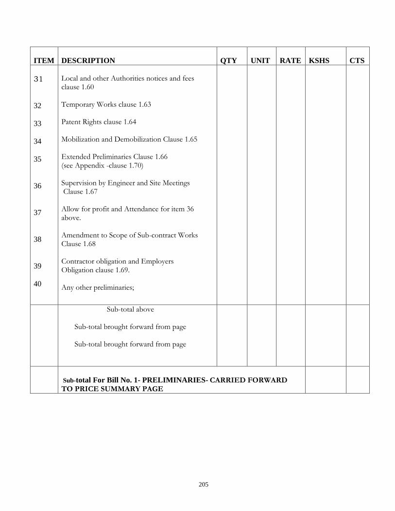
205
ITEM
DESCRIPTION
QTY
UNIT
RATE
KSHS
CTS
31
32
33
34
35
36
37
38
39
40
Local and other Authorities notices and fees clause 1.60 Temporary Works clause 1.63 Patent Rights clause 1.64 Mobilization and Demobilization Clause 1.65 Extended Preliminaries Clause 1.66 (see Appendix -clause 1.70) Supervision by Engineer and Site Meetings Clause 1.67 Allow for profit and Attendance for item 36 above. Amendment to Scope of Sub-contract Works Clause 1.68 Contractor obligation and Employers Obligation clause 1.69.
Any other preliminaries;
Sub-total above
Sub-total brought forward from page
Sub-total brought forward from page
Sub-total For Bill No. 1- PRELIMINARIES- CARRIED FORWARD TO PRICE SUMMARY PAGE
206
SECTION I
TECHNICAL SCHEDULE
OF
ITEMS TO BE SUPPLIED

207
TECHNICAL SCHEDULE
The technical schedule shall be submitted by tenderers to facilitate and enable the Project
Manager to evaluate the tenders, especially where the tenderer intends to supply or has based his
tender sum on equipment which differs in manufacture, type or performance from the
specifications indicated by the Project Manager.
Any tender without this shall be disqualified.
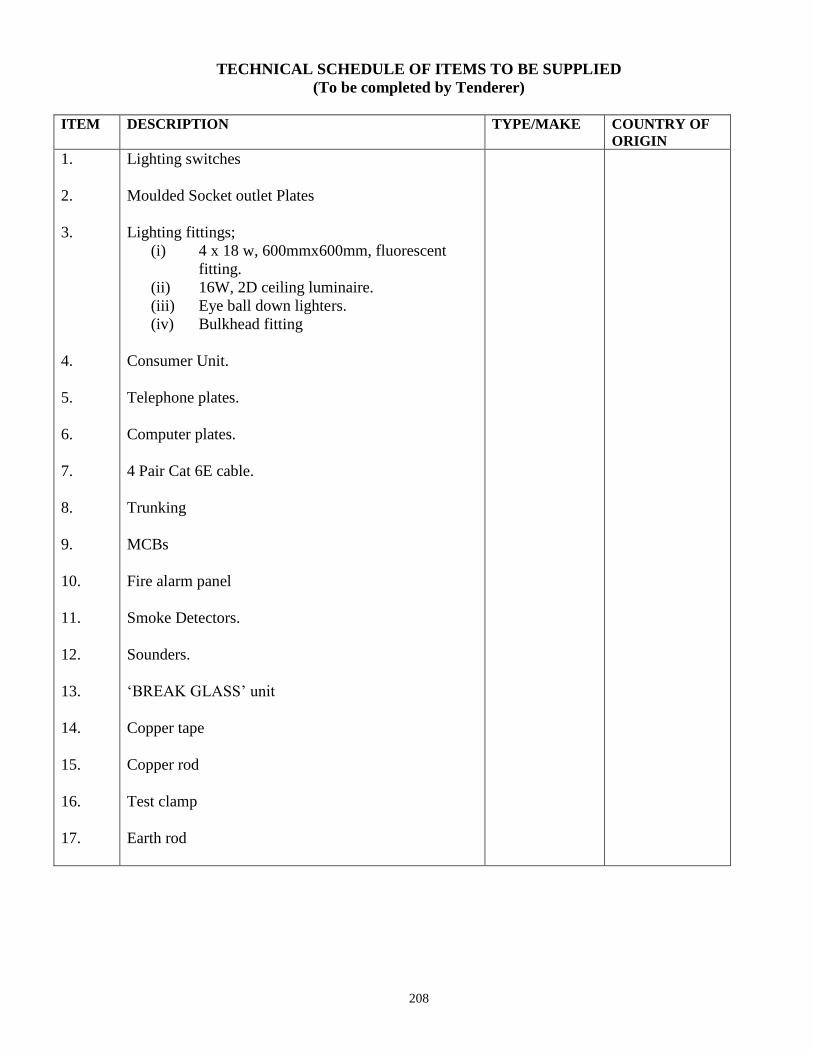
208
TECHNICAL SCHEDULE OF ITEMS TO BE SUPPLIED
(To be completed by Tenderer)
ITEM DESCRIPTION TYPE/MAKE COUNTRY OF
ORIGIN
1.
2.
3.
4.
5.
6.
7.
8.
9.
10.
11.
12.
13.
14.
15.
16.
17.
Lighting switches
Moulded Socket outlet Plates
Lighting fittings;
(i) 4 x 18 w, 600mmx600mm, fluorescent
fitting.
(ii) 16W, 2D ceiling luminaire.
(iii) Eye ball down lighters.
(iv) Bulkhead fitting
Consumer Unit.
Telephone plates.
Computer plates.
4 Pair Cat 6E cable.
Trunking
MCBs
Fire alarm panel
Smoke Detectors.
Sounders.
‘BREAK GLASS’ unit
Copper tape
Copper rod
Test clamp
Earth rod

209
PRELIMINARIES
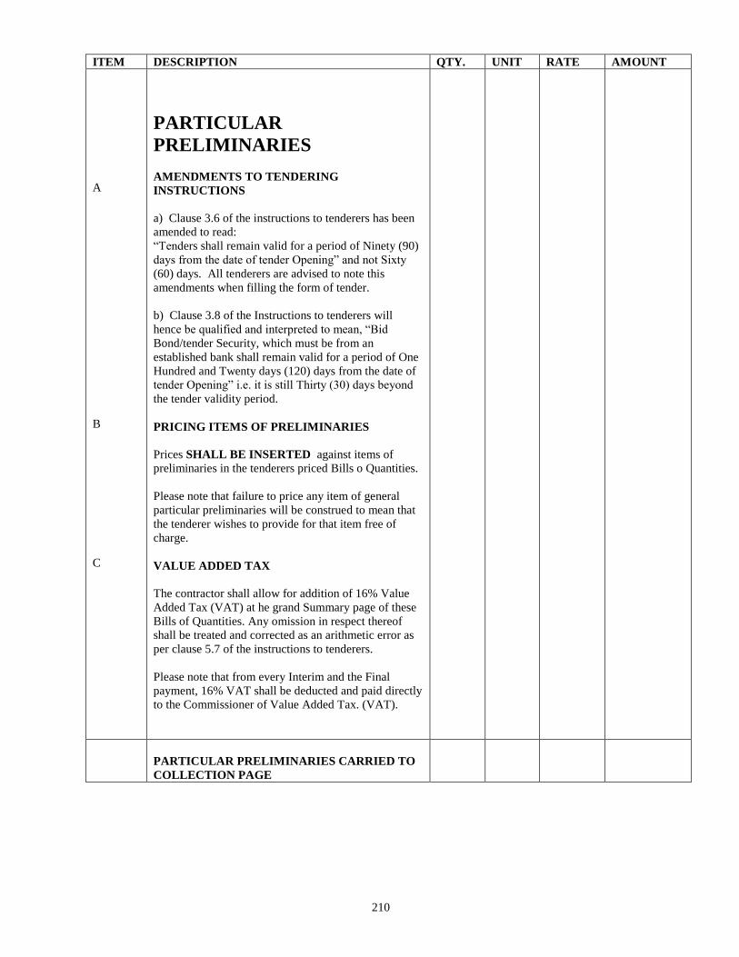
210
ITEM DESCRIPTION QTY. UNIT RATE AMOUNT
A
B
C
PARTICULAR
PRELIMINARIES
AMENDMENTS TO TENDERING
INSTRUCTIONS
a) Clause 3.6 of the instructions to tenderers has been
amended to read:
“Tenders shall remain valid for a period of Ninety (90)
days from the date of tender Opening” and not Sixty
(60) days. All tenderers are advised to note this
amendments when filling the form of tender.
b) Clause 3.8 of the Instructions to tenderers will
hence be qualified and interpreted to mean, “Bid
Bond/tender Security, which must be from an
established bank shall remain valid for a period of One
Hundred and Twenty days (120) days from the date of
tender Opening” i.e. it is still Thirty (30) days beyond
the tender validity period.
PRICING ITEMS OF PRELIMINARIES
Prices SHALL BE INSERTED against items of
preliminaries in the tenderers priced Bills o Quantities.
Please note that failure to price any item of general
particular preliminaries will be construed to mean that
the tenderer wishes to provide for that item free of
charge.
VALUE ADDED TAX
The contractor shall allow for addition of 16% Value
Added Tax (VAT) at he grand Summary page of these
Bills of Quantities. Any omission in respect thereof
shall be treated and corrected as an arithmetic error as
per clause 5.7 of the instructions to tenderers.
Please note that from every Interim and the Final
payment, 16% VAT shall be deducted and paid directly
to the Commissioner of Value Added Tax. (VAT).
PARTICULAR PRELIMINARIES CARRIED TO
COLLECTION PAGE
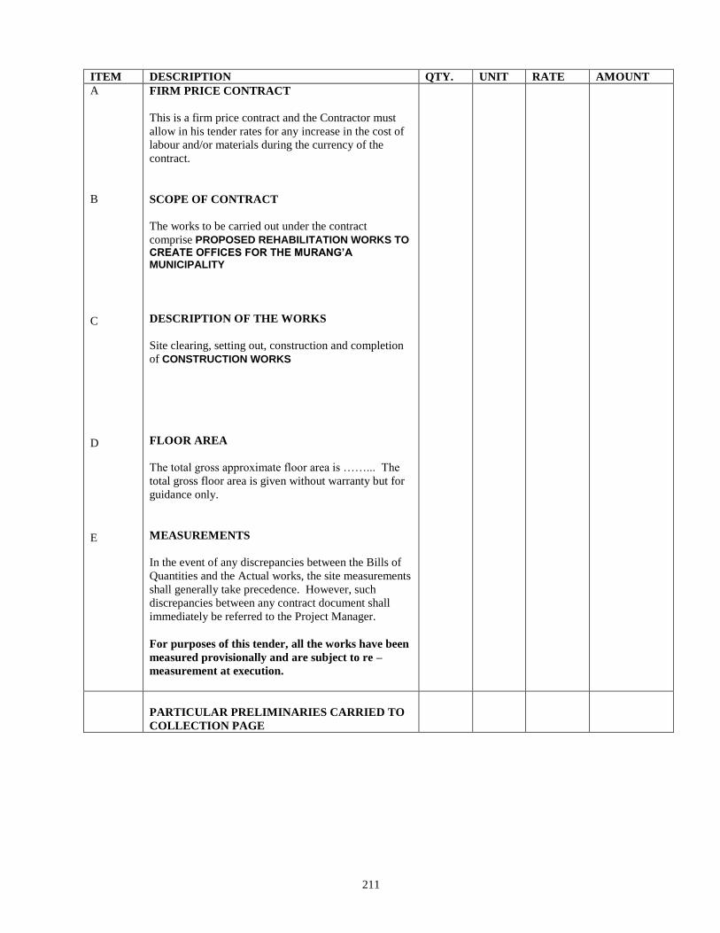
211
ITEM DESCRIPTION QTY. UNIT RATE AMOUNT
A
B
C
D
E
FIRM PRICE CONTRACT
This is a firm price contract and the Contractor must
allow in his tender rates for any increase in the cost of
labour and/or materials during the currency of the
contract.
SCOPE OF CONTRACT
The works to be carried out under the contract
comprise PROPOSED REHABILITATION WORKS TO
CREATE OFFICES FOR THE MURANG’A MUNICIPALITY
DESCRIPTION OF THE WORKS
Site clearing, setting out, construction and completion
of CONSTRUCTION WORKS
FLOOR AREA
The total gross approximate floor area is ……... The
total gross floor area is given without warranty but for
guidance only.
MEASUREMENTS
In the event of any discrepancies between the Bills of
Quantities and the Actual works, the site measurements
shall generally take precedence. However, such
discrepancies between any contract document shall
immediately be referred to the Project Manager.
For purposes of this tender, all the works have been
measured provisionally and are subject to re –
measurement at execution.
PARTICULAR PRELIMINARIES CARRIED TO
COLLECTION PAGE
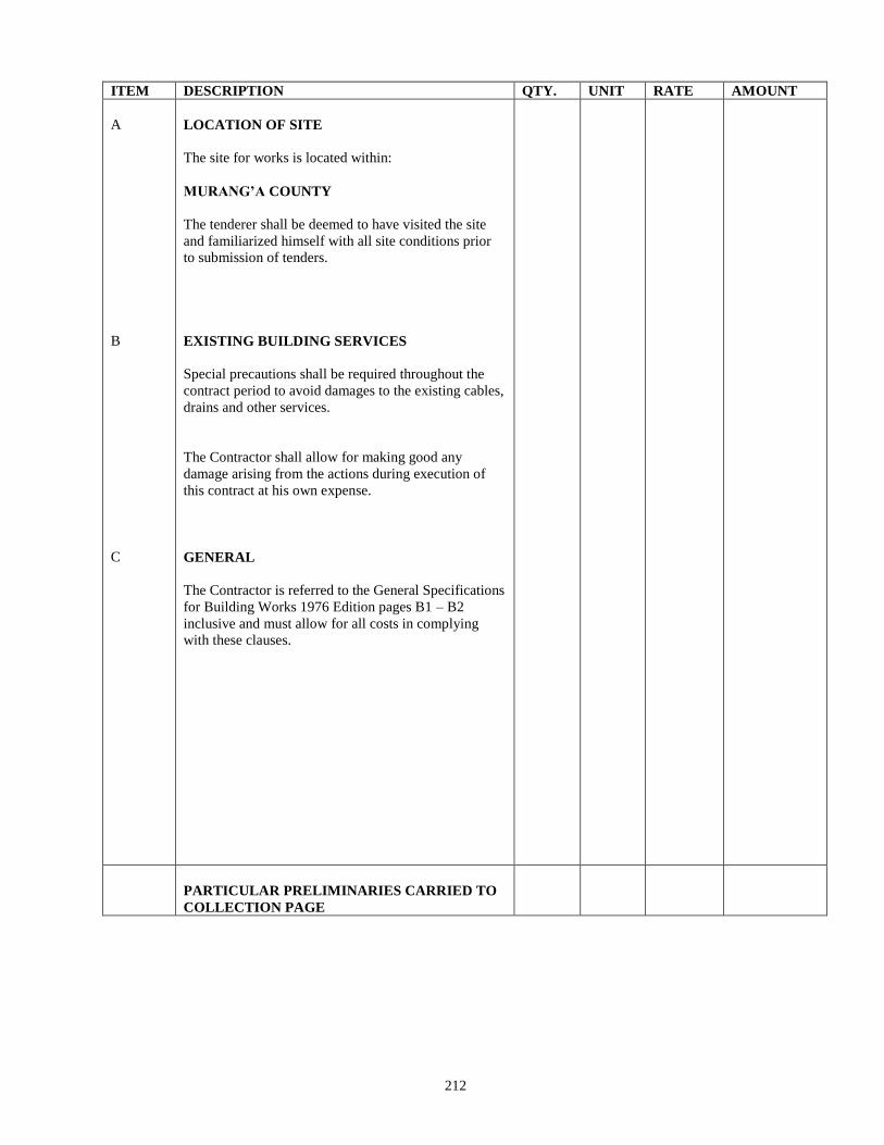
212
ITEM DESCRIPTION QTY. UNIT RATE AMOUNT
A
B
C
LOCATION OF SITE
The site for works is located within:
MURANG’A COUNTY
The tenderer shall be deemed to have visited the site
and familiarized himself with all site conditions prior
to submission of tenders.
EXISTING BUILDING SERVICES
Special precautions shall be required throughout the
contract period to avoid damages to the existing cables,
drains and other services.
The Contractor shall allow for making good any
damage arising from the actions during execution of
this contract at his own expense.
GENERAL
The Contractor is referred to the General Specifications
for Building Works 1976 Edition pages B1 – B2
inclusive and must allow for all costs in complying
with these clauses.
PARTICULAR PRELIMINARIES CARRIED TO
COLLECTION PAGE
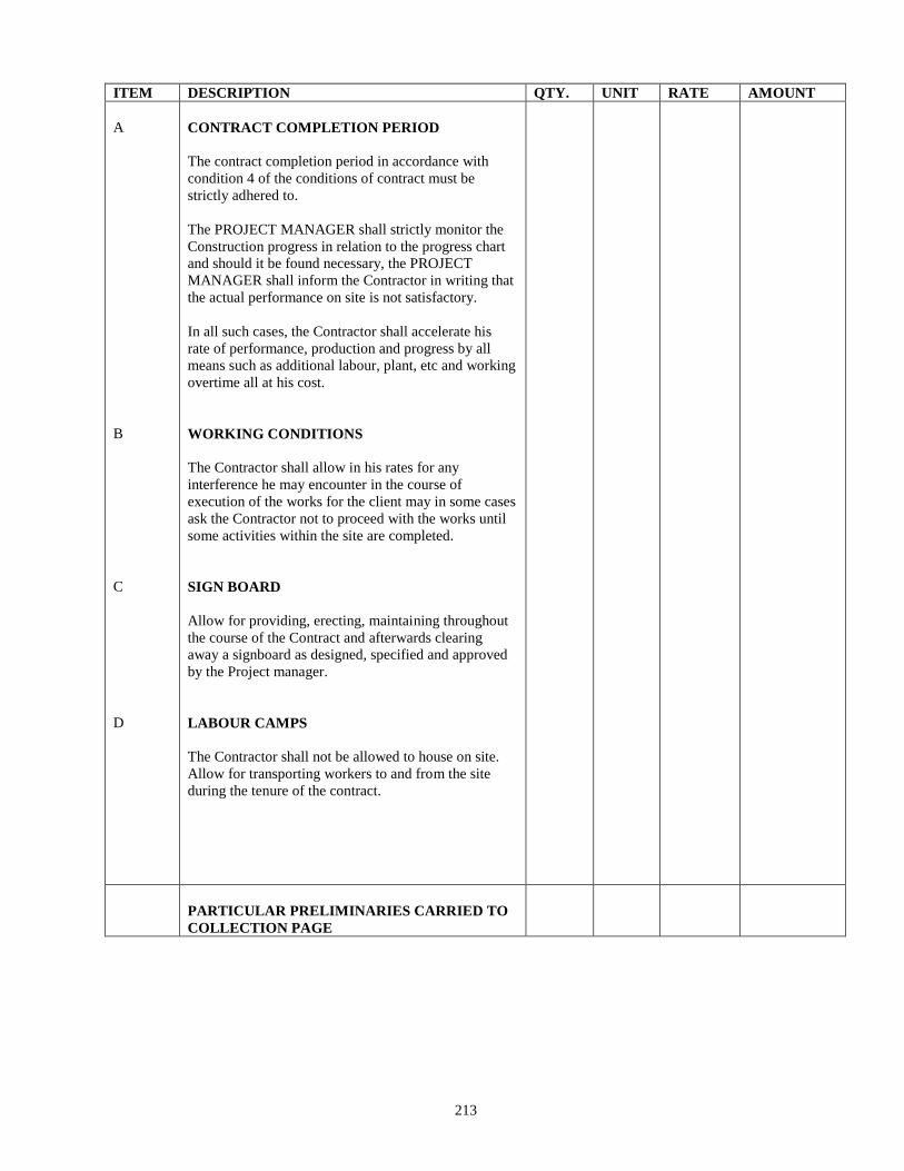
213
ITEM DESCRIPTION QTY. UNIT RATE AMOUNT
A
B
C
D
CONTRACT COMPLETION PERIOD
The contract completion period in accordance with
condition 4 of the conditions of contract must be
strictly adhered to.
The PROJECT MANAGER shall strictly monitor the
Construction progress in relation to the progress chart
and should it be found necessary, the PROJECT
MANAGER shall inform the Contractor in writing that
the actual performance on site is not satisfactory.
In all such cases, the Contractor shall accelerate his
rate of performance, production and progress by all
means such as additional labour, plant, etc and working
overtime all at his cost.
WORKING CONDITIONS
The Contractor shall allow in his rates for any
interference he may encounter in the course of
execution of the works for the client may in some cases
ask the Contractor not to proceed with the works until
some activities within the site are completed.
SIGN BOARD
Allow for providing, erecting, maintaining throughout
the course of the Contract and afterwards clearing
away a signboard as designed, specified and approved
by the Project manager.
LABOUR CAMPS
The Contractor shall not be allowed to house on site.
Allow for transporting workers to and from the site
during the tenure of the contract.
PARTICULAR PRELIMINARIES CARRIED TO
COLLECTION PAGE
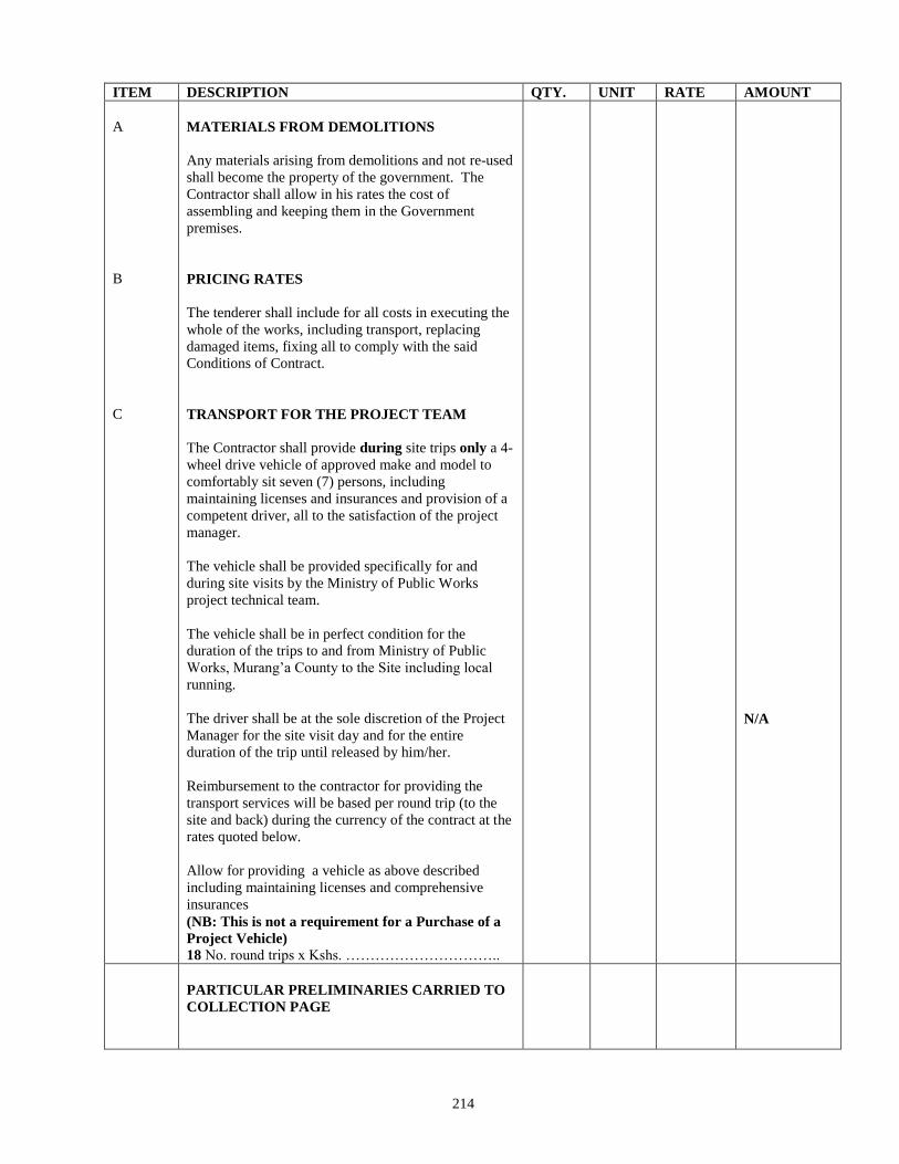
214
ITEM DESCRIPTION QTY. UNIT RATE AMOUNT
A
B
C
MATERIALS FROM DEMOLITIONS
Any materials arising from demolitions and not re-used
shall become the property of the government. The
Contractor shall allow in his rates the cost of
assembling and keeping them in the Government
premises.
PRICING RATES
The tenderer shall include for all costs in executing the
whole of the works, including transport, replacing
damaged items, fixing all to comply with the said
Conditions of Contract.
TRANSPORT FOR THE PROJECT TEAM
The Contractor shall provide during site trips only a 4-
wheel drive vehicle of approved make and model to
comfortably sit seven (7) persons, including
maintaining licenses and insurances and provision of a
competent driver, all to the satisfaction of the project
manager.
The vehicle shall be provided specifically for and
during site visits by the Ministry of Public Works
project technical team.
The vehicle shall be in perfect condition for the
duration of the trips to and from Ministry of Public
Works, Murang’a County to the Site including local
running.
The driver shall be at the sole discretion of the Project
Manager for the site visit day and for the entire
duration of the trip until released by him/her.
Reimbursement to the contractor for providing the
transport services will be based per round trip (to the
site and back) during the currency of the contract at the
rates quoted below.
Allow for providing a vehicle as above described
including maintaining licenses and comprehensive
insurances
(NB: This is not a requirement for a Purchase of a
Project Vehicle)
18 No. round trips x Kshs. …………………………..
N/A
PARTICULAR PRELIMINARIES CARRIED TO
COLLECTION PAGE
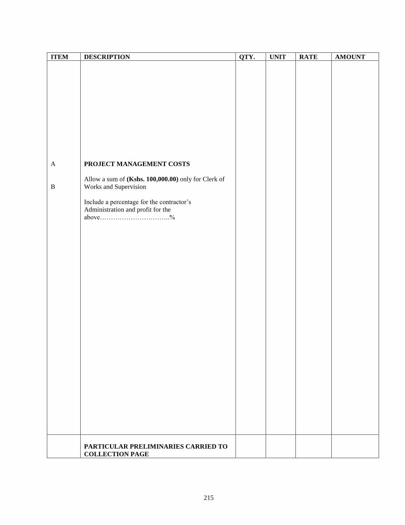
215
ITEM DESCRIPTION QTY. UNIT RATE AMOUNT
A
B
PROJECT MANAGEMENT COSTS
Allow a sum of (Kshs. 100,000.00) only for Clerk of
Works and Supervision
Include a percentage for the contractor’s
Administration and profit for the
above…………………………..%
PARTICULAR PRELIMINARIES CARRIED TO
COLLECTION PAGE
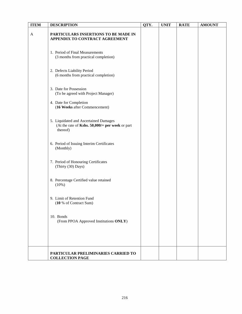
216
ITEM DESCRIPTION QTY. UNIT RATE AMOUNT
A
PARTICULARS INSERTIONS TO BE MADE IN
APPENDIX TO CONTRACT AGREEMENT
1. Period of Final Measurements
(3 months from practical completion)
2. Defects Liability Period
(6 months from practical completion)
3. Date for Possession
(To be agreed with Project Manager)
4. Date for Completion
(16 Weeks after Commencement)
5. Liquidated and Ascertained Damages
(At the rate of Kshs. 50,000/= per week or part
thereof)
6. Period of Issuing Interim Certificates
(Monthly)
7. Period of Honouring Certificates
(Thirty (30) Days)
8. Percentage Certified value retained
(10%)
9. Limit of Retention Fund
(10 % of Contract Sum)
10. Bonds
(From PPOA Approved Institutions ONLY)
PARTICULAR PRELIMINARIES CARRIED TO
COLLECTION PAGE
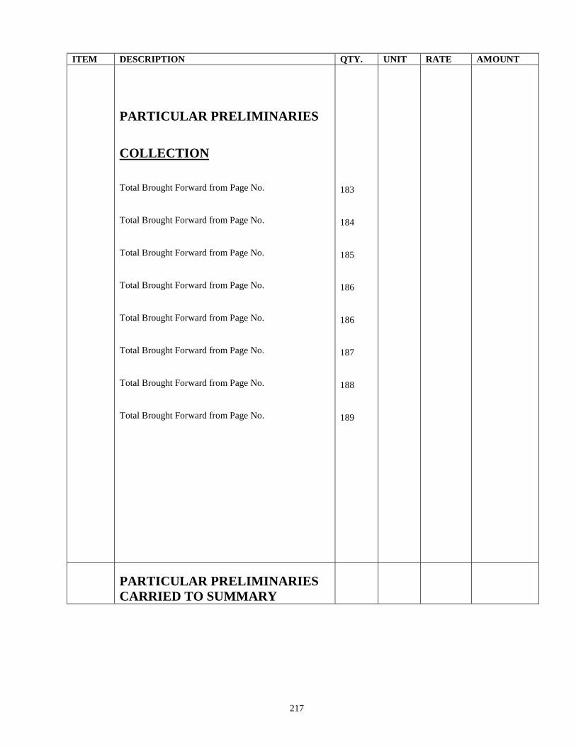
217
ITEM DESCRIPTION QTY. UNIT RATE AMOUNT
PARTICULAR PRELIMINARIES
COLLECTION
Total Brought Forward from Page No.
Total Brought Forward from Page No.
Total Brought Forward from Page No.
Total Brought Forward from Page No.
Total Brought Forward from Page No.
Total Brought Forward from Page No.
Total Brought Forward from Page No.
Total Brought Forward from Page No.
183
184
185
186
186
187
188
189
PARTICULAR PRELIMINARIES
CARRIED TO SUMMARY
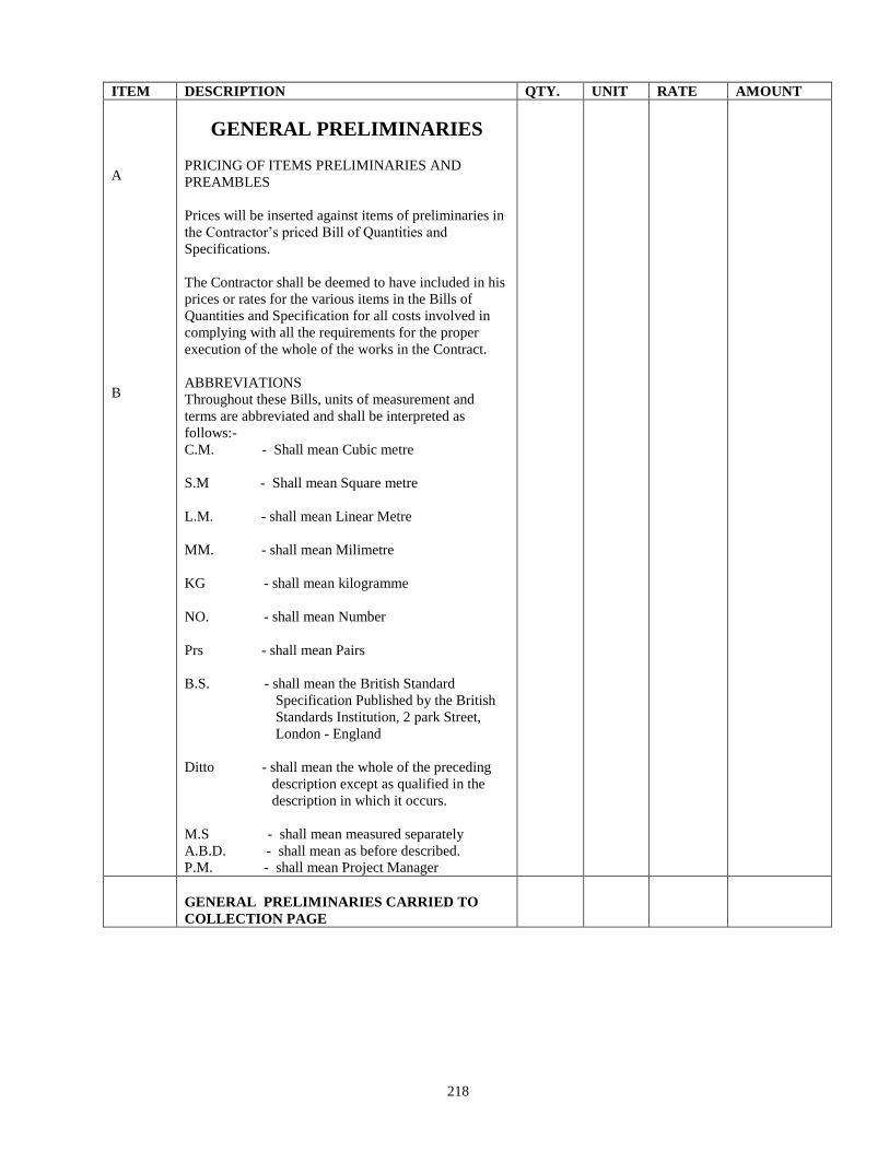
218
ITEM DESCRIPTION QTY. UNIT RATE AMOUNT
A
B
GENERAL PRELIMINARIES
PRICING OF ITEMS PRELIMINARIES AND
PREAMBLES
Prices will be inserted against items of preliminaries in
the Contractor’s priced Bill of Quantities and
Specifications.
The Contractor shall be deemed to have included in his
prices or rates for the various items in the Bills of
Quantities and Specification for all costs involved in
complying with all the requirements for the proper
execution of the whole of the works in the Contract.
ABBREVIATIONS
Throughout these Bills, units of measurement and
terms are abbreviated and shall be interpreted as
follows:-
C.M. - Shall mean Cubic metre
S.M - Shall mean Square metre
L.M. - shall mean Linear Metre
MM. - shall mean Milimetre
KG - shall mean kilogramme
NO. - shall mean Number
Prs - shall mean Pairs
B.S. - shall mean the British Standard
Specification Published by the British
Standards Institution, 2 park Street,
London - England
Ditto - shall mean the whole of the preceding
description except as qualified in the
description in which it occurs.
M.S - shall mean measured separately
A.B.D. - shall mean as before described.
P.M. - shall mean Project Manager
GENERAL PRELIMINARIES CARRIED TO
COLLECTION PAGE
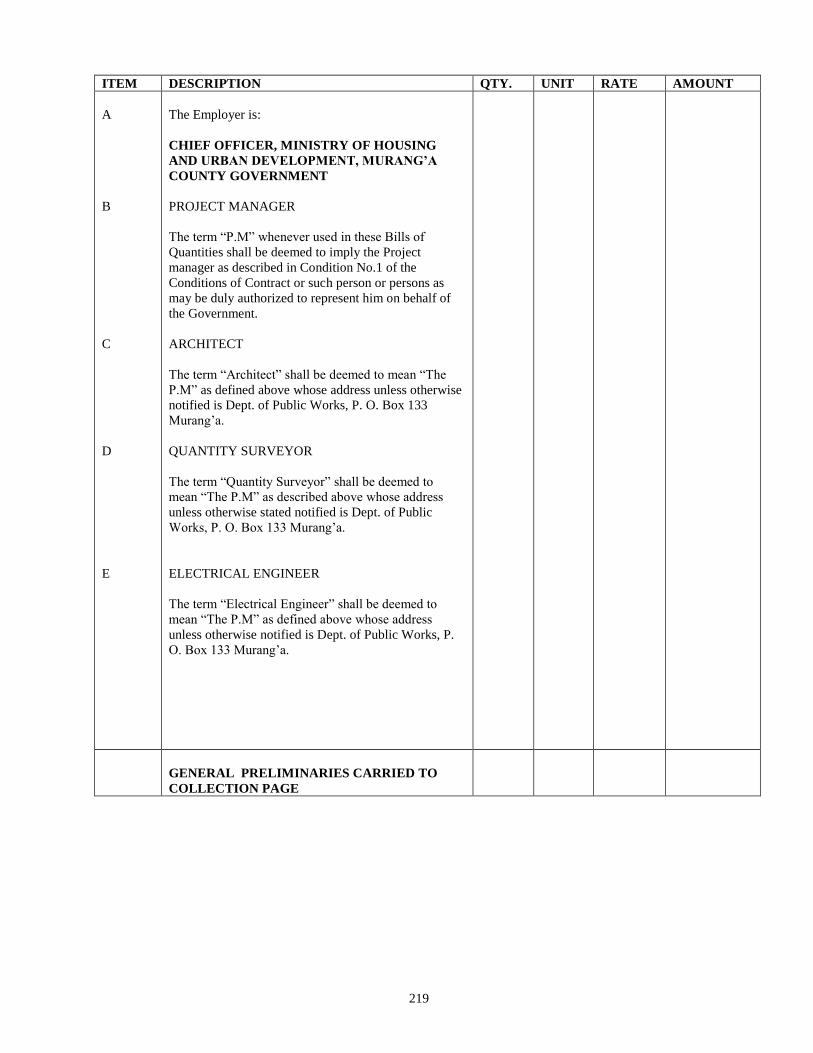
219
ITEM DESCRIPTION QTY. UNIT RATE AMOUNT
A
B
C
D
E
The Employer is:
CHIEF OFFICER, MINISTRY OF HOUSING
AND URBAN DEVELOPMENT, MURANG’A
COUNTY GOVERNMENT
PROJECT MANAGER
The term “P.M” whenever used in these Bills of
Quantities shall be deemed to imply the Project
manager as described in Condition No.1 of the
Conditions of Contract or such person or persons as
may be duly authorized to represent him on behalf of
the Government.
ARCHITECT
The term “Architect” shall be deemed to mean “The
P.M” as defined above whose address unless otherwise
notified is Dept. of Public Works, P. O. Box 133
Murang’a.
QUANTITY SURVEYOR
The term “Quantity Surveyor” shall be deemed to
mean “The P.M” as described above whose address
unless otherwise stated notified is Dept. of Public
Works, P. O. Box 133 Murang’a.
ELECTRICAL ENGINEER
The term “Electrical Engineer” shall be deemed to
mean “The P.M” as defined above whose address
unless otherwise notified is Dept. of Public Works, P.
O. Box 133 Murang’a.
GENERAL PRELIMINARIES CARRIED TO
COLLECTION PAGE
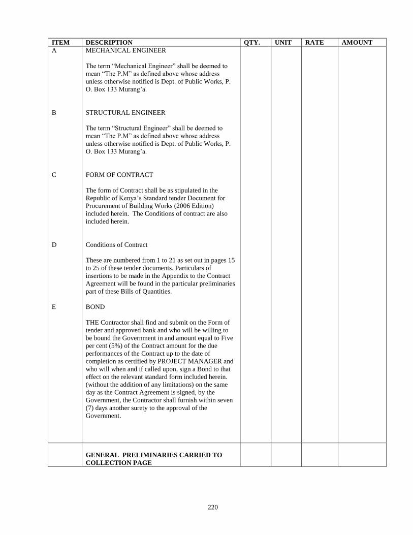
220
ITEM DESCRIPTION QTY. UNIT RATE AMOUNT
A
B
C
D
E
MECHANICAL ENGINEER
The term “Mechanical Engineer” shall be deemed to
mean “The P.M” as defined above whose address
unless otherwise notified is Dept. of Public Works, P.
O. Box 133 Murang’a.
STRUCTURAL ENGINEER
The term “Structural Engineer” shall be deemed to
mean “The P.M” as defined above whose address
unless otherwise notified is Dept. of Public Works, P.
O. Box 133 Murang’a.
FORM OF CONTRACT
The form of Contract shall be as stipulated in the
Republic of Kenya’s Standard tender Document for
Procurement of Building Works (2006 Edition)
included herein. The Conditions of contract are also
included herein.
Conditions of Contract
These are numbered from 1 to 21 as set out in pages 15
to 25 of these tender documents. Particulars of
insertions to be made in the Appendix to the Contract
Agreement will be found in the particular preliminaries
part of these Bills of Quantities.
BOND
THE Contractor shall find and submit on the Form of
tender and approved bank and who will be willing to
be bound the Government in and amount equal to Five
per cent (5%) of the Contract amount for the due
performances of the Contract up to the date of
completion as certified by PROJECT MANAGER and
who will when and if called upon, sign a Bond to that
effect on the relevant standard form included herein.
(without the addition of any limitations) on the same
day as the Contract Agreement is signed, by the
Government, the Contractor shall furnish within seven
(7) days another surety to the approval of the
Government.
GENERAL PRELIMINARIES CARRIED TO
COLLECTION PAGE
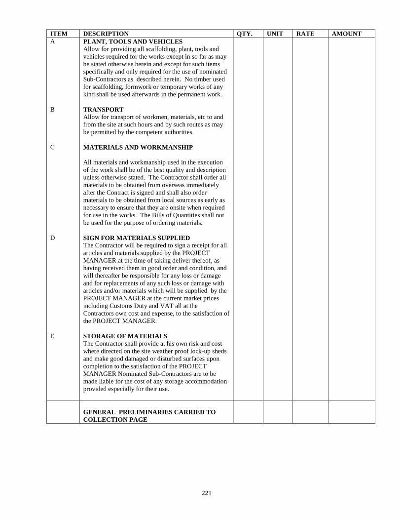
221
ITEM DESCRIPTION QTY. UNIT RATE AMOUNT
A
B
C
D
E
PLANT, TOOLS AND VEHICLES
Allow for providing all scaffolding, plant, tools and
vehicles required for the works except in so far as may
be stated otherwise herein and except for such items
specifically and only required for the use of nominated
Sub-Contractors as described herein. No timber used
for scaffolding, formwork or temporary works of any
kind shall be used afterwards in the permanent work.
TRANSPORT
Allow for transport of workmen, materials, etc to and
from the site at such hours and by such routes as may
be permitted by the competent authorities.
MATERIALS AND WORKMANSHIP
All materials and workmanship used in the execution
of the work shall be of the best quality and description
unless otherwise stated. The Contractor shall order all
materials to be obtained from overseas immediately
after the Contract is signed and shall also order
materials to be obtained from local sources as early as
necessary to ensure that they are onsite when required
for use in the works. The Bills of Quantities shall not
be used for the purpose of ordering materials.
SIGN FOR MATERIALS SUPPLIED
The Contractor will be required to sign a receipt for all
articles and materials supplied by the PROJECT
MANAGER at the time of taking deliver thereof, as
having received them in good order and condition, and
will thereafter be responsible for any loss or damage
and for replacements of any such loss or damage with
articles and/or materials which will be supplied by the
PROJECT MANAGER at the current market prices
including Customs Duty and VAT all at the
Contractors own cost and expense, to the satisfaction of
the PROJECT MANAGER.
STORAGE OF MATERIALS
The Contractor shall provide at his own risk and cost
where directed on the site weather proof lock-up sheds
and make good damaged or disturbed surfaces upon
completion to the satisfaction of the PROJECT
MANAGER Nominated Sub-Contractors are to be
made liable for the cost of any storage accommodation
provided especially for their use.
GENERAL PRELIMINARIES CARRIED TO
COLLECTION PAGE
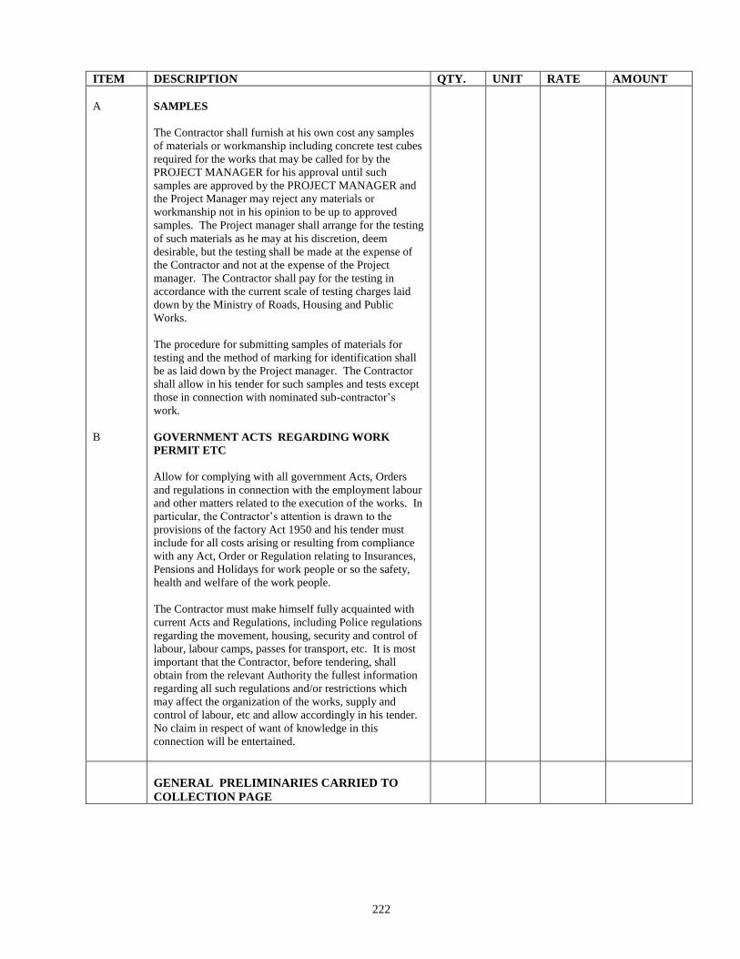
222
ITEM DESCRIPTION QTY. UNIT RATE AMOUNT
A
B
SAMPLES
The Contractor shall furnish at his own cost any samples
of materials or workmanship including concrete test cubes
required for the works that may be called for by the
PROJECT MANAGER for his approval until such
samples are approved by the PROJECT MANAGER and
the Project Manager may reject any materials or
workmanship not in his opinion to be up to approved
samples. The Project manager shall arrange for the testing
of such materials as he may at his discretion, deem
desirable, but the testing shall be made at the expense of
the Contractor and not at the expense of the Project
manager. The Contractor shall pay for the testing in
accordance with the current scale of testing charges laid
down by the Ministry of Roads, Housing and Public
Works.
The procedure for submitting samples of materials for
testing and the method of marking for identification shall
be as laid down by the Project manager. The Contractor
shall allow in his tender for such samples and tests except
those in connection with nominated sub-contractor’s
work.
GOVERNMENT ACTS REGARDING WORK
PERMIT ETC
Allow for complying with all government Acts, Orders
and regulations in connection with the employment labour
and other matters related to the execution of the works. In
particular, the Contractor’s attention is drawn to the
provisions of the factory Act 1950 and his tender must
include for all costs arising or resulting from compliance
with any Act, Order or Regulation relating to Insurances,
Pensions and Holidays for work people or so the safety,
health and welfare of the work people.
The Contractor must make himself fully acquainted with
current Acts and Regulations, including Police regulations
regarding the movement, housing, security and control of
labour, labour camps, passes for transport, etc. It is most
important that the Contractor, before tendering, shall
obtain from the relevant Authority the fullest information
regarding all such regulations and/or restrictions which
may affect the organization of the works, supply and
control of labour, etc and allow accordingly in his tender.
No claim in respect of want of knowledge in this
connection will be entertained.
GENERAL PRELIMINARIES CARRIED TO
COLLECTION PAGE
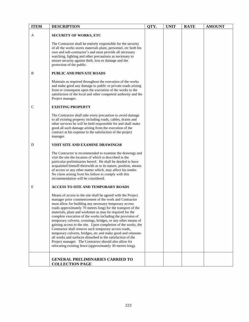
223
ITEM DESCRIPTION QTY. UNIT RATE AMOUNT
A
B
C
D
E
SECURITY OF WORKS, ETC
The Contractor shall be entirely responsible for the security
of all the works stores materials plant, personnel, etc both his
own and sub-contractor’s and must provide all necessary
watching, lighting and other precautions as necessary to
ensure security against theft, loss or damage and the
protection of the public.
PUBLIC AND PRIVATE ROADS
Maintain as required throughout the execution of the works
and make good any damage to public or private roads arising
from or consequent upon the execution of the works to the
satisfaction of the local and other competent authority and the
Project manager.
EXISTING PROPERTY
The Contractor shall take every precaution to avoid damage
to all existing property including roads, cables, drains and
other services he will be held responsible for and shall make
good all such damage arising from the execution of the
contract at his expense to the satisfaction of the project
manager.
VISIT SITE AND EXAMINE DRAWINGS8
The Contractor is recommended to examine the drawings and
visit the site the location of which is described in the
particular preliminaries hereof. He shall be deeded to have
acquainted himself therewith as to its nature, position, means
of access or any other matter which, may affect his tender.
No claim arising from his failure to comply with this
recommendation will be considered.
ACCESS TO SITE AND TEMPORARY ROADS
Means of access to the site shall be agreed with the Project
manager prior commencement of the work and Contractor
must allow for building any necessary temporary access
roads approximately 70 metres long) for the transport of the
materials, plant and workmen as may be required for the
complete execution of the works including the provision of
temporary culverts, crossings, bridges, or any other means of
gaining access to the site. Upon completion of the works, the
Contractor shall remove such temporary access roads,
temporary culverts, bridges, etc and make good and reinstate
all works and surfaces disturbed to the satisfaction of the
Project manager. The Contractor should also allow for
relocating existing fence (approximately 30 metres long).
GENERAL PRELIMINARIES CARRIED TO
COLLECTION PAGE
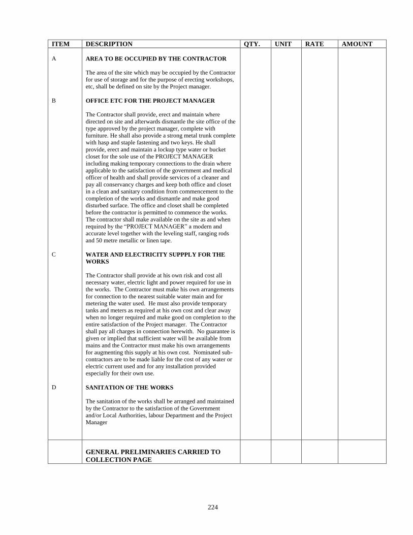
224
ITEM DESCRIPTION QTY. UNIT RATE AMOUNT
A
B
C
D
AREA TO BE OCCUPIED BY THE CONTRACTOR
The area of the site which may be occupied by the Contractor
for use of storage and for the purpose of erecting workshops,
etc, shall be defined on site by the Project manager.
OFFICE ETC FOR THE PROJECT MANAGER
The Contractor shall provide, erect and maintain where
directed on site and afterwards dismantle the site office of the
type approved by the project manager, complete with
furniture. He shall also provide a strong metal trunk complete
with hasp and staple fastening and two keys. He shall
provide, erect and maintain a lockup type water or bucket
closet for the sole use of the PROJECT MANAGER
including making temporary connections to the drain where
applicable to the satisfaction of the government and medical
officer of health and shall provide services of a cleaner and
pay all conservancy charges and keep both office and closet
in a clean and sanitary condition from commencement to the
completion of the works and dismantle and make good
disturbed surface. The office and closet shall be completed
before the contractor is permitted to commence the works.
The contractor shall make available on the site as and when
required by the “PROJECT MANAGER” a modern and
accurate level together with the leveling staff, ranging rods
and 50 metre metallic or linen tape.
WATER AND ELECTRICITY SUPPPLY FOR THE
WORKS
The Contractor shall provide at his own risk and cost all
necessary water, electric light and power required for use in
the works. The Contractor must make his own arrangements
for connection to the nearest suitable water main and for
metering the water used. He must also provide temporary
tanks and meters as required at his own cost and clear away
when no longer required and make good on completion to the
entire satisfaction of the Project manager. The Contractor
shall pay all charges in connection herewith. No guarantee is
given or implied that sufficient water will be available from
mains and the Contractor must make his own arrangements
for augmenting this supply at his own cost. Nominated sub-
contractors are to be made liable for the cost of any water or
electric current used and for any installation provided
especially for their own use.
SANITATION OF THE WORKS
The sanitation of the works shall be arranged and maintained
by the Contractor to the satisfaction of the Government
and/or Local Authorities, labour Department and the Project
Manager
GENERAL PRELIMINARIES CARRIED TO
COLLECTION PAGE
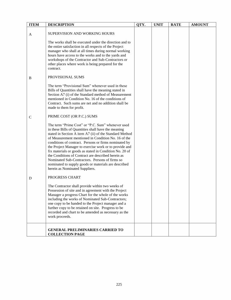
225
ITEM DESCRIPTION QTY. UNIT RATE AMOUNT
A
B
C
D
SUPERVISION AND WORKING HOURS
The works shall be executed under the direction and to
the entire satisfaction in all respects of the Project
manager who shall at all times during normal working
hours have access to the works and to the yards and
workshops of the Contractor and Sub-Contractors or
other places where work is being prepared for the
contract.
PROVISIONAL SUMS
The term “Provisional Sum” whenever used in these
Bills of Quantities shall have the meaning stated in
Section A7 (i) of the Standard method of Measurement
mentioned in Condition No. 16 of the conditions of
Contract. Such sums are net and no addition shall be
made to them for profit.
PRIME COST (OR P.C.) SUMS
The term “Prime Cost” or “P.C. Sum” whenever used
in these Bills of Quantities shall have the meaning
stated in Section A item A7 (ii) of the Standard Method
of Measurement mentioned in Condition No. 16 of the
conditions of contract. Persons or firms nominated by
the Project Manager to exercise work or to provide and
fix materials or goods as stated in Condition No. 20 of
the Conditions of Contract are described herein as
Nominated Sub-Contractors. Persons of firms so
nominated to supply goods or materials are described
herein as Nominated Suppliers.
PROGRESS CHART
The Contractor shall provide within two weeks of
Possession of site and in agreement with the Project
Manager a progress Chart for the whole of the works
including the works of Nominated Sub-Contractors;
one copy to be handed to the Project manager and a
further copy to be retained on site. Progress to be
recorded and chart to be amended as necessary as the
work proceeds.
GENERAL PRELIMINARIES CARRIED TO
COLLECTION PAGE
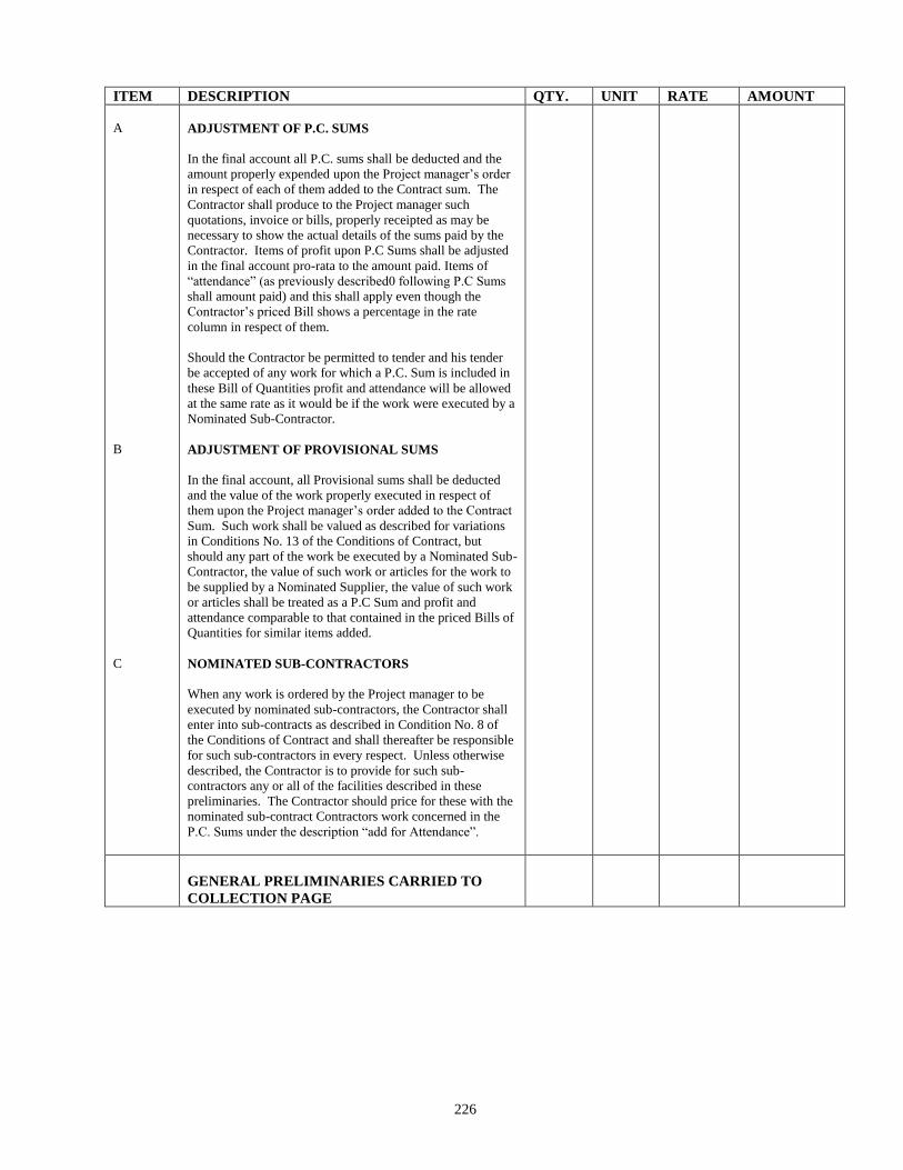
226
ITEM DESCRIPTION QTY. UNIT RATE AMOUNT
A
B
C
ADJUSTMENT OF P.C. SUMS
In the final account all P.C. sums shall be deducted and the
amount properly expended upon the Project manager’s order
in respect of each of them added to the Contract sum. The
Contractor shall produce to the Project manager such
quotations, invoice or bills, properly receipted as may be
necessary to show the actual details of the sums paid by the
Contractor. Items of profit upon P.C Sums shall be adjusted
in the final account pro-rata to the amount paid. Items of
“attendance” (as previously described0 following P.C Sums
shall amount paid) and this shall apply even though the
Contractor’s priced Bill shows a percentage in the rate
column in respect of them.
Should the Contractor be permitted to tender and his tender
be accepted of any work for which a P.C. Sum is included in
these Bill of Quantities profit and attendance will be allowed
at the same rate as it would be if the work were executed by a
Nominated Sub-Contractor.
ADJUSTMENT OF PROVISIONAL SUMS
In the final account, all Provisional sums shall be deducted
and the value of the work properly executed in respect of
them upon the Project manager’s order added to the Contract
Sum. Such work shall be valued as described for variations
in Conditions No. 13 of the Conditions of Contract, but
should any part of the work be executed by a Nominated Sub-
Contractor, the value of such work or articles for the work to
be supplied by a Nominated Supplier, the value of such work
or articles shall be treated as a P.C Sum and profit and
attendance comparable to that contained in the priced Bills of
Quantities for similar items added.
NOMINATED SUB-CONTRACTORS
When any work is ordered by the Project manager to be
executed by nominated sub-contractors, the Contractor shall
enter into sub-contracts as described in Condition No. 8 of
the Conditions of Contract and shall thereafter be responsible
for such sub-contractors in every respect. Unless otherwise
described, the Contractor is to provide for such sub-
contractors any or all of the facilities described in these
preliminaries. The Contractor should price for these with the
nominated sub-contract Contractors work concerned in the
P.C. Sums under the description “add for Attendance”.
GENERAL PRELIMINARIES CARRIED TO
COLLECTION PAGE
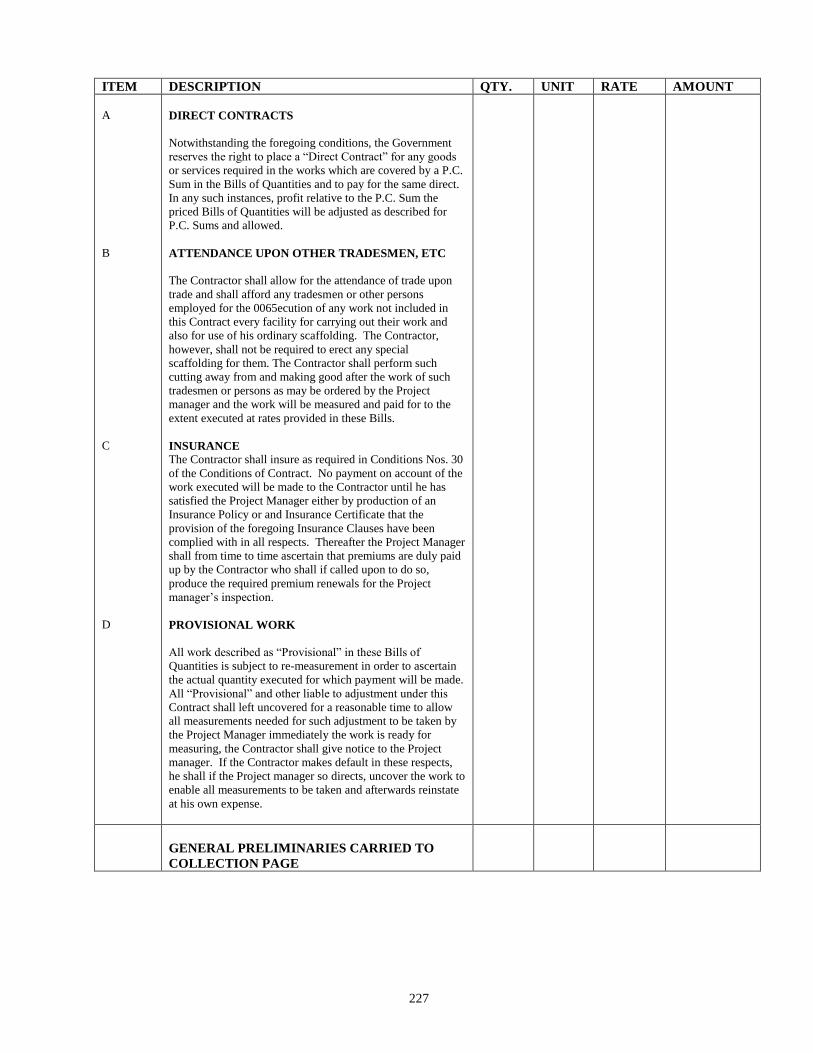
227
ITEM DESCRIPTION QTY. UNIT RATE AMOUNT
A
B
C
D
DIRECT CONTRACTS
Notwithstanding the foregoing conditions, the Government
reserves the right to place a “Direct Contract” for any goods
or services required in the works which are covered by a P.C.
Sum in the Bills of Quantities and to pay for the same direct.
In any such instances, profit relative to the P.C. Sum the
priced Bills of Quantities will be adjusted as described for
P.C. Sums and allowed.
ATTENDANCE UPON OTHER TRADESMEN, ETC
The Contractor shall allow for the attendance of trade upon
trade and shall afford any tradesmen or other persons
employed for the 0065ecution of any work not included in
this Contract every facility for carrying out their work and
also for use of his ordinary scaffolding. The Contractor,
however, shall not be required to erect any special
scaffolding for them. The Contractor shall perform such
cutting away from and making good after the work of such
tradesmen or persons as may be ordered by the Project
manager and the work will be measured and paid for to the
extent executed at rates provided in these Bills.
INSURANCE
The Contractor shall insure as required in Conditions Nos. 30
of the Conditions of Contract. No payment on account of the
work executed will be made to the Contractor until he has
satisfied the Project Manager either by production of an
Insurance Policy or and Insurance Certificate that the
provision of the foregoing Insurance Clauses have been
complied with in all respects. Thereafter the Project Manager
shall from time to time ascertain that premiums are duly paid
up by the Contractor who shall if called upon to do so,
produce the required premium renewals for the Project
manager’s inspection.
PROVISIONAL WORK
All work described as “Provisional” in these Bills of
Quantities is subject to re-measurement in order to ascertain
the actual quantity executed for which payment will be made.
All “Provisional” and other liable to adjustment under this
Contract shall left uncovered for a reasonable time to allow
all measurements needed for such adjustment to be taken by
the Project Manager immediately the work is ready for
measuring, the Contractor shall give notice to the Project
manager. If the Contractor makes default in these respects,
he shall if the Project manager so directs, uncover the work to
enable all measurements to be taken and afterwards reinstate
at his own expense.
GENERAL PRELIMINARIES CARRIED TO
COLLECTION PAGE
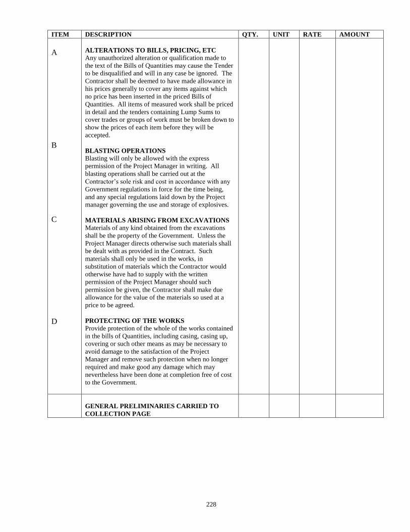
228
ITEM DESCRIPTION QTY. UNIT RATE AMOUNT
A
B
C
D
ALTERATIONS TO BILLS, PRICING, ETC
Any unauthorized alteration or qualification made to
the text of the Bills of Quantities may cause the Tender
to be disqualified and will in any case be ignored. The
Contractor shall be deemed to have made allowance in
his prices generally to cover any items against which
no price has been inserted in the priced Bills of
Quantities. All items of measured work shall be priced
in detail and the tenders containing Lump Sums to
cover trades or groups of work must be broken down to
show the prices of each item before they will be
accepted.
BLASTING OPERATIONS
Blasting will only be allowed with the express
permission of the Project Manager in writing. All
blasting operations shall be carried out at the
Contractor’s sole risk and cost in accordance with any
Government regulations in force for the time being,
and any special regulations laid down by the Project
manager governing the use and storage of explosives.
MATERIALS ARISING FROM EXCAVATIONS
Materials of any kind obtained from the excavations
shall be the property of the Government. Unless the
Project Manager directs otherwise such materials shall
be dealt with as provided in the Contract. Such
materials shall only be used in the works, in
substitution of materials which the Contractor would
otherwise have had to supply with the written
permission of the Project Manager should such
permission be given, the Contractor shall make due
allowance for the value of the materials so used at a
price to be agreed.
PROTECTING OF THE WORKS
Provide protection of the whole of the works contained
in the bills of Quantities, including casing, casing up,
covering or such other means as may be necessary to
avoid damage to the satisfaction of the Project
Manager and remove such protection when no longer
required and make good any damage which may
nevertheless have been done at completion free of cost
to the Government.
GENERAL PRELIMINARIES CARRIED TO
COLLECTION PAGE
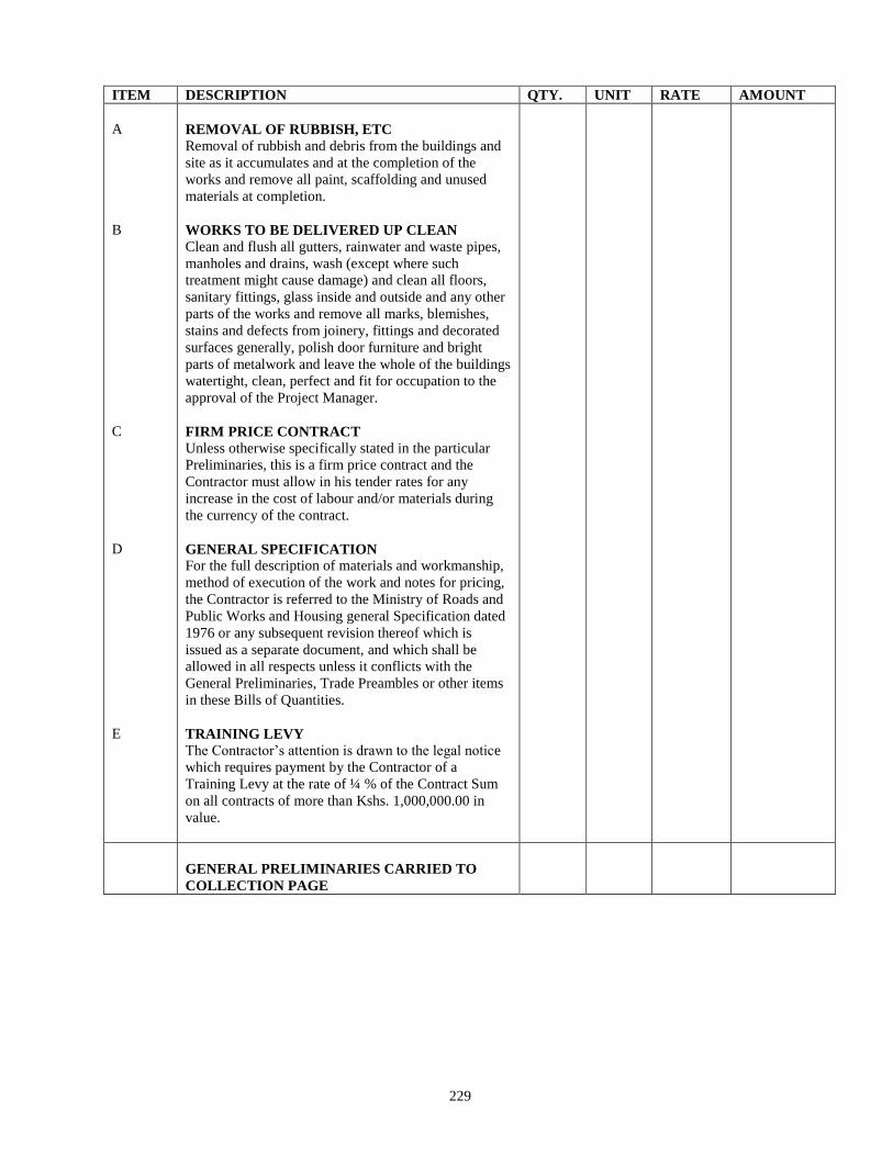
229
ITEM DESCRIPTION QTY. UNIT RATE AMOUNT
A
B
C
D
E
REMOVAL OF RUBBISH, ETC
Removal of rubbish and debris from the buildings and
site as it accumulates and at the completion of the
works and remove all paint, scaffolding and unused
materials at completion.
WORKS TO BE DELIVERED UP CLEAN
Clean and flush all gutters, rainwater and waste pipes,
manholes and drains, wash (except where such
treatment might cause damage) and clean all floors,
sanitary fittings, glass inside and outside and any other
parts of the works and remove all marks, blemishes,
stains and defects from joinery, fittings and decorated
surfaces generally, polish door furniture and bright
parts of metalwork and leave the whole of the buildings
watertight, clean, perfect and fit for occupation to the
approval of the Project Manager.
FIRM PRICE CONTRACT
Unless otherwise specifically stated in the particular
Preliminaries, this is a firm price contract and the
Contractor must allow in his tender rates for any
increase in the cost of labour and/or materials during
the currency of the contract.
GENERAL SPECIFICATION
For the full description of materials and workmanship,
method of execution of the work and notes for pricing,
the Contractor is referred to the Ministry of Roads and
Public Works and Housing general Specification dated
1976 or any subsequent revision thereof which is
issued as a separate document, and which shall be
allowed in all respects unless it conflicts with the
General Preliminaries, Trade Preambles or other items
in these Bills of Quantities.
TRAINING LEVY
The Contractor’s attention is drawn to the legal notice
which requires payment by the Contractor of a
Training Levy at the rate of ¼ % of the Contract Sum
on all contracts of more than Kshs. 1,000,000.00 in
value.
GENERAL PRELIMINARIES CARRIED TO
COLLECTION PAGE
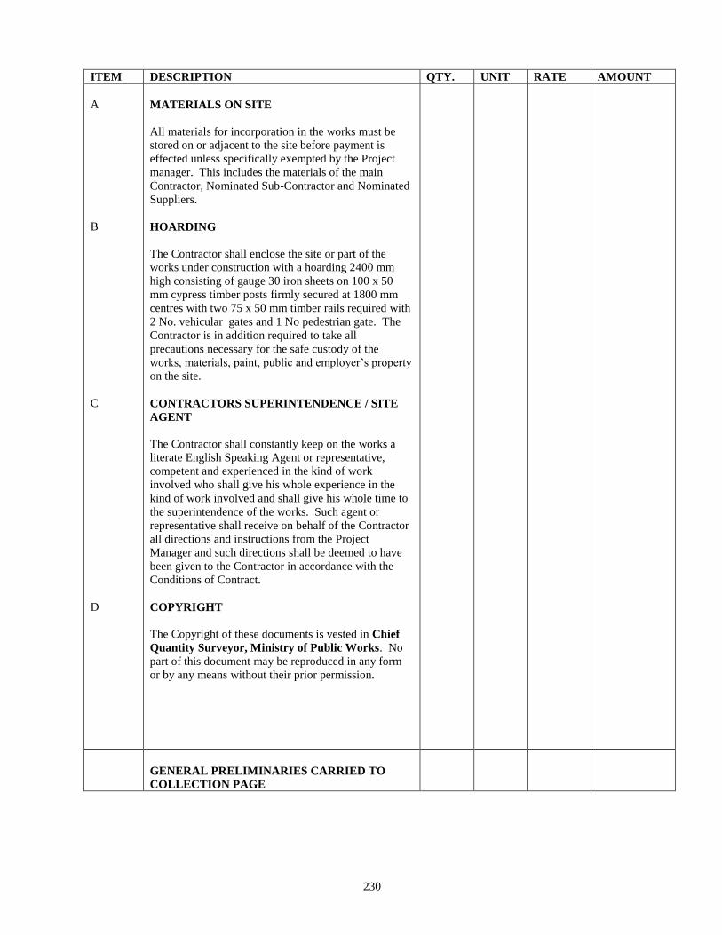
230
ITEM DESCRIPTION QTY. UNIT RATE AMOUNT
A
B
C
D
MATERIALS ON SITE
All materials for incorporation in the works must be
stored on or adjacent to the site before payment is
effected unless specifically exempted by the Project
manager. This includes the materials of the main
Contractor, Nominated Sub-Contractor and Nominated
Suppliers.
HOARDING
The Contractor shall enclose the site or part of the
works under construction with a hoarding 2400 mm
high consisting of gauge 30 iron sheets on 100 x 50
mm cypress timber posts firmly secured at 1800 mm
centres with two 75 x 50 mm timber rails required with
2 No. vehicular gates and 1 No pedestrian gate. The
Contractor is in addition required to take all
precautions necessary for the safe custody of the
works, materials, paint, public and employer’s property
on the site.
CONTRACTORS SUPERINTENDENCE / SITE
AGENT
The Contractor shall constantly keep on the works a
literate English Speaking Agent or representative,
competent and experienced in the kind of work
involved who shall give his whole experience in the
kind of work involved and shall give his whole time to
the superintendence of the works. Such agent or
representative shall receive on behalf of the Contractor
all directions and instructions from the Project
Manager and such directions shall be deemed to have
been given to the Contractor in accordance with the
Conditions of Contract.
COPYRIGHT
The Copyright of these documents is vested in Chief
Quantity Surveyor, Ministry of Public Works. No
part of this document may be reproduced in any form
or by any means without their prior permission.
GENERAL PRELIMINARIES CARRIED TO
COLLECTION PAGE
231
ITEM DESCRIPTION QTY. UNIT RATE AMOUNT
GENERAL PRELIMINARIES
COLLECTION
Total Brought Forward from Page No.
Total Brought Forward from Page No.
Total Brought Forward from Page No.
Total Brought Forward from Page No.
Total Brought Forward from Page No.
Total Brought Forward from Page No.
Total Brought Forward from Page No.
Total Brought Forward from Page No.
Total Brought Forward from Page No.
Total Brought Forward from Page No.
Total Brought Forward from Page No.
Total Brought Forward from Page No.
Total Brought Forward from Page No.
191
192
193
194
195
196
197
198
199
200
201
202
203
GENERAL PRELIMINARIES
CARRIED TO SUMMARY
232
ITEM DESCRIPTION QTY. UNIT RATE AMOUNT
SUMMARY OF PRELIMINARIES
PARTICULAR PRELIMINARIES from Page 190
GENERAL PRELIMINARIES from Page 204
PARTICULAR & GENERAL
PRELIMINARIES CARRIED TO
GRAND SUMMARY
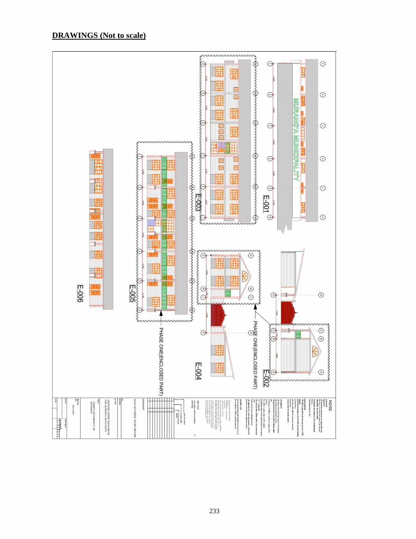
233
DRAWINGS (Not to scale)
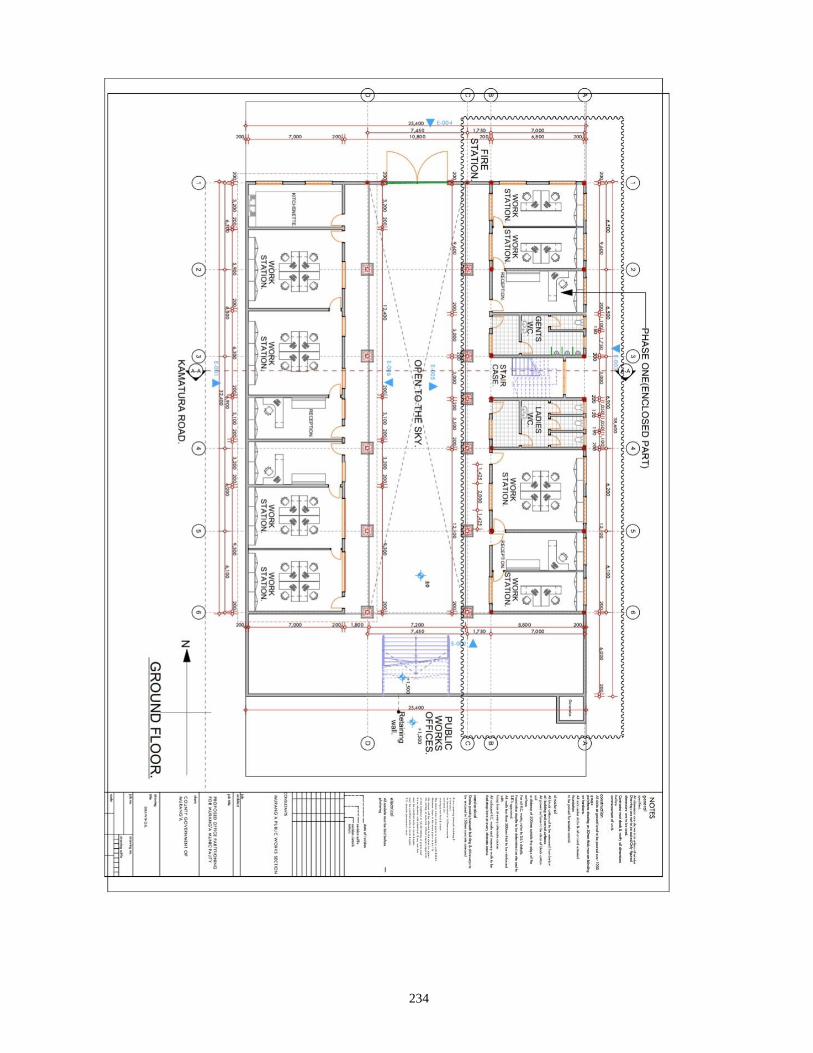
234
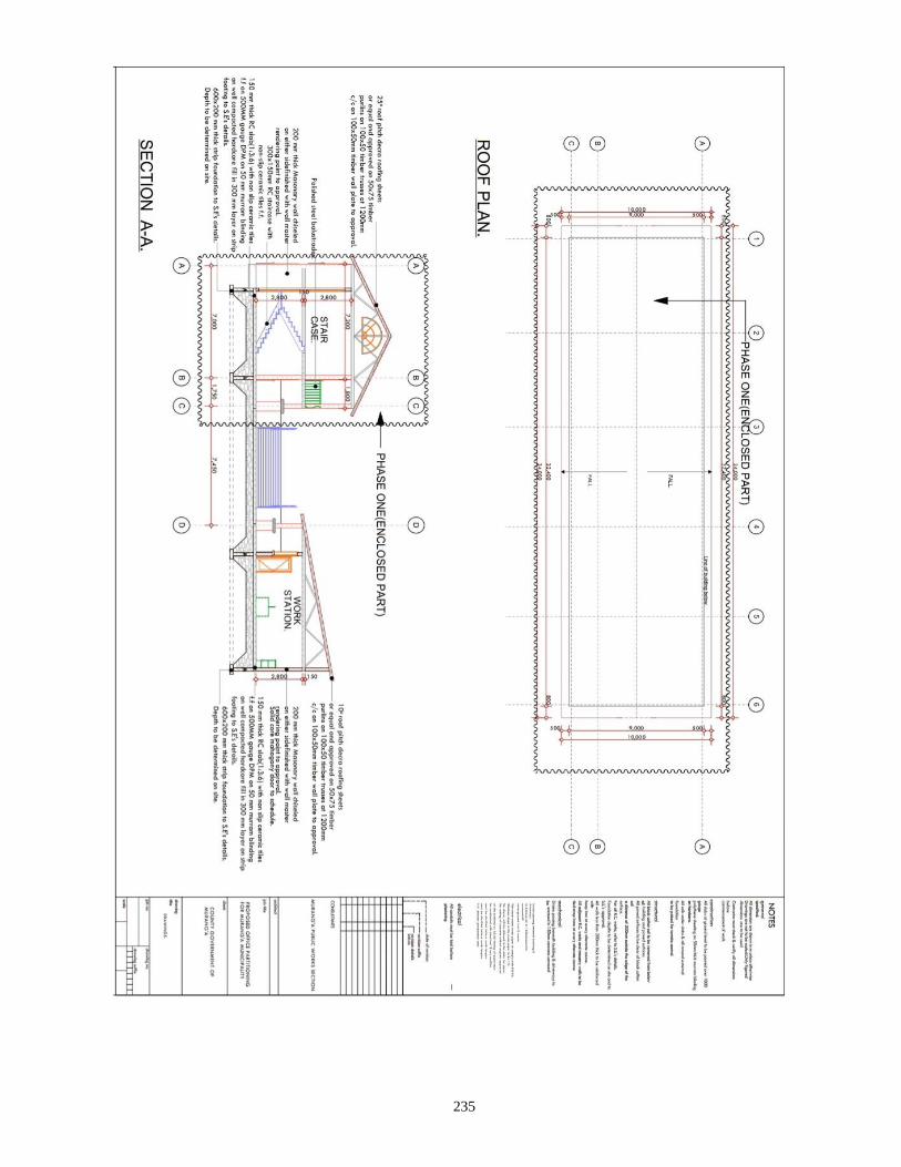
235
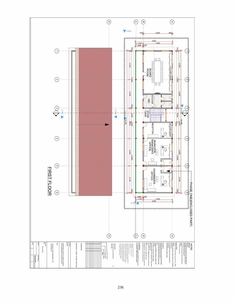
236