Embed Size (px)
Citation preview

E – 1
MENU
ENTER
CANCEL
SELECT
POWER STATUS
ON/STAND BY
SOURCE
AUTO ADJUST
AC IN
S-VIDEO
VIDEO
AUDIO
RGB INPUT 2
AUDIO
RGB INPUT 1
L/MONO
R
AUDIO
RGB MONITOR
OUTPUT
USB
PC-CARD
C CONTROLMOUSEOUT
REMOCONTRINPU
MultiSync MT1055/MT1050/MT850
LCD ProjectorUser’s Manual
English

E – 2
IMPORTANT INFORMATIONPrecautionsPlease read this manual carefully before using your NEC MultiSyncMT1055/MT1050/MT850 Projector and keep the manual handy for fu-ture reference.Your serial number is located under the name plate label on the leftside of your MultiSync MT1055/MT1050/MT850. Record it here:
CAUTIONTo turn off main power, be sure to remove the plug frompower outlet.The power outlet socket should be installed as near tothe equipment as possible, and should be easily acces-sible.
CAUTIONTO PREVENT SHOCK, DO NOT OPEN THE CABINET.NO USER-SERVICEABLE PARTS INSIDE.REFER SERVICING TO QUALIFIED NEC SERVICEPERSONNEL.
This symbol warns the user that uninsulated voltagewithin the unit may be sufficient to cause electrical shock.Therefore, it is dangerous to make any kind of contactwith any part inside of the unit.
This symbol alerts the user that important informationconcerning the operation and maintenance of this unithas been provided. The information should be read care-fully to avoid problems.
WARNINGTO PREVENT FIRE OR SHOCK, DO NOT EXPOSE THIS UNIT TORAIN OR MOISTURE.DO NOT USE THIS UNIT’S GROUNDED PLUG WITH AN EXTEN-SION CORD OR IN AN OUTLET UNLESS ALL THREE PRONGS CANBE FULLY INSERTED.DO NOT OPEN THE CABINET. THERE ARE HIGH-VOLTAGE COM-PONENTS INSIDE. ALL SERVICING MUST BE DONE BY QUALI-FIED NEC SERVICE PERSONNEL.
DOC Compliance NoticeThis Class B digital apparatus meets all requirements of the CanadianInterference-Causing Equipment Regulations.
3. GSGV Acoustic Noise Information Ordinance:The sound pressure level is less than 70 dB (A) according to ISO 3744or ISO 7779.
RF InterferenceWARNINGThe Federal Communications Commission does not allow anymodifications or changes to the unit EXCEPT those specified byNEC Technologies in this manual. Failure to comply with this gov-ernment regulation could void your right to operate this equip-ment.This equipment has been tested and found to comply with thelimits for a Class B digital device, pursuant to Part 15 of the FCCRules. These limits are designed to provide reasonable protectionagainst harmful interference in a residential installation. This equip-ment generates, uses, and can radiate radio frequency energyand, if not installed and used in accordance with the instructions,may cause harmful interference to radio communications. How-ever, there is no guarantee that interference will not occur in aparticular installation. If this equipment does cause harmful inter-ference to radio or television reception, which can be determinedby turning the equipment off and on, the user is encouraged to tryto correct the interference by one or more of the following mea-sures:• Reorient or relocate the receiving antenna.• Increase the separation between the equipment and receiver.• Connect the equipment into an outlet on a circuit different from that to
which the receiver is connected.• Consult the dealer or an experienced radio / TV technician for help.
In UK, a BS approved power cable with moulded plug has a Black (fiveAmps) fuse installed for use with this equipment. If a power cable is notsupplied with this equipment please contact your supplier.
C A U T I O NLASER RADIATION-DO NOT STATE INTO BEAM
RADIACION LASERNO MIRE AL RAYOPRODUCTO LASER CLASSE2LASER-STRAHLUNGNICHT IN DEN STRAHLBLICKEN ! LASER KLASSE2RAYONNEMENT LASER NE PASREGARDER DANS LE FAISCEAUAPPAREIL A LASER DE CLASSE2
EN60825-1 : 1994 + A11 : 1996 MADE IN CHINA
WAVE LENGTH: 650nmMAX. OUTPUT: 1mWCLASS 2 LASER PRODUCT
REMOTECONTROLMODEL:RD-367E7N900011
• IBM is a registered trademark of International Business MachinesCorporation.
• Macintosh and PowerBook are registered trademarks of Apple Com-puter, Inc.
• Other product and company names mentioned in this user's manualmay be the trademarks of their respective holders.
This label is located on the back of the remote control.

E – 3
Important SafeguardsThese safety instructions are to ensure the long life of your projectorand to prevent fire and shock. Please read them carefully and heed allwarnings.
Installation1. For best results, use your projector in a darkened room.2. Place the projector on a flat, level surface in a dry area away from
dust and moisture.3. Do not place your projector in direct sunlight, near heaters or heat
radiating appliances.4. Exposure to direct sunlight, smoke or steam can harm internal com-
ponents.5. Handle your projector carefully. Dropping or jarring can damage in-
ternal components.6. Do not place heavy objects on top of the projector.7. If you wish to have the projector installed on the ceiling:
a. Do not attempt to install the projector yourself.b. The projector must be installed by qualified technicians in order to ensure
proper operation and reduce the risk of bodily injury.c. In addition, the ceiling must be strong enough to support the projector
and the installation must be in accordance with any local building codes.d. Please consult your dealer for more information.
Power Supply1. The projector is designed to operate on a power supply of 100-120
or 200-240 V 50/60 Hz AC. Ensure that your power supply fits thisrequirement before attempting to use your projector.
2. Handle the power cable carefully and avoid excessive bending. Adamaged cord can cause electric shock or fire.
3. If the projector is not to be used for an extended period of time,disconnect the plug from the power outlet.
Cleaning1. Unplug the projector before cleaning.2. Clean the cabinet periodically with a damp cloth. If heavily soiled,
use a mild detergent. Never use strong detergents or solvents suchas alcohol or thinner.
3. Use a blower or lens paper to clean the lens, and be careful not toscratch or mar the lens.
CAUTIONDo not unplug the power cable from the wall outlet under any oneof the following circumstances. Doing so can cause damage tothe projector:• While the Hour Glass icon appears.• While the message "Please wait a moment." appears. This message
will be displayed after the projector is turned off.• Immediately after the power cable is plugged into the wall outlet (the
POWER indicator has not changed to a steady orange glow).• Immediately after the cooling fan stops working (The cooling fan con-
tinues to work for ONE minute after the projector is turned off with thePOWER button).
• While the POWER and the STATUS indicators are alternately flashing.
CAUTIONDo not put the projector on its side when the lamp is turned on.Doing so may cause damage to the projector.
Lamp Replacement• To replace the lamp, follow all instructions provided on page E-47.• Be sure to replace the lamp when the message "The Lamp has
reached the end of its usable life. Please replace the lamp."appears. If you continue to use the lamp after the lamp has reachedthe end of its usable life, the lamp bulb may shatter, and pieces ofglass may be scattered in the lamp case. Do not touch them as thepieces of glass may cause injury. If this happens, contact your NECdealer for lamp replacement.
• Allow a minimum of ONE minute to elapse after turning off the pro-jector. Then disconnect the power cable and allow 60 minutes tocool the projector before replacing the lamp.
Fire and Shock Precautions1. Ensure that there is sufficient ventilation and that vents are unob-
structed to prevent the build-up of heat inside your projector. Allowat least 3 inches (10 cm) of space between your projector and awall.
2. Prevent foreign objects such as paper clips and bits of paper fromfalling into your projector. Do not attempt to retrieve any objects thatmight fall into your projector. Do not insert any metal objects such asa wire or screwdriver into your projector. If something should fall intoyour projector, disconnect it immediately and have the object re-moved by a qualified NEC service personnel.
3. Do not place any liquids on top of your projector.• Do not look into the lens while the projector is on. Serious damage
to your eyes could result.• Keep any items such as magnifying glass out of the light path of the
projector. The light being projected from the lens is extensive, there-fore any kind of abnormal objects that can redirect light coming outof the lens, can cause unpredictable outcome such as fire or injuryto the eyes.
• Do not cover the lens with the supplied lens cap or equivalent whilethe projector is on. Doing so can lead to melting of the cap andpossibly burning your hands due to the heat emitted from the lightoutput.
• Do not look into the laser pointer while it is on and do not point thelaser beam at another person. Serious injury could result.

E – 4
TABLE OF CONTENTS1. INTRODUCTIONIntroduction to the MultiSync MT1055/MT1050/MT850 Projector .......... E-5Getting Started ............................................................................. E-5What's in the Box ......................................................................... E-6Getting to Know Your MultiSync MT1055/MT1050/MT850 Projector ...... E-7
Front / Side Features ............................................................. E-7Rear / Side Features .............................................................. E-7Top Features .......................................................................... E-8Terminal Panel Features ........................................................ E-9Remote Control Features .................................................... E-10
Remote Control Battery Installation .............................. E-12Operating Range ........................................................... E-12Remote Control Precautions ......................................... E-12Switching Operation mode between mouse and projector ..... E-13
2. INSTALLATIONSetting Up Your Projector ........................................................... E-14Selecting a Location ................................................................... E-14Using a Tabletop or Cart ............................................................ E-14Adjusting the Tilt Foot ................................................................. E-15Distance Chart ........................................................................... E-16Ceiling Installation ...................................................................... E-16Reflecting the Image .................................................................. E-16Wiring Diagram .......................................................................... E-18
Connecting Your PC ............................................................. E-19Connecting Your Macintosh Computer ................................. E-20Connecting Your Computer to the Mouse Output Port ......... E-21Connecting an External Monitor .......................................... E-21Connecting Your DVD Player ............................................... E-22Connecting Your VCR or Laser Disc Player ......................... E-23
About Startup screen (Menu Language Select screen) ............. E-24
3. OPERATIONGeneral Controls ........................................................................ E-25
Using the Menus .................................................................. E-25Using a USB Mouse ............................................................ E-25Basic Operation ................................................................... E-26Adjust the Image Using Auto Adjust .................................... E-26Using Pointer ....................................................................... E-27Enlarging and Moving a Picture ........................................... E-27Correcting Keystone Distortion ............................................ E-28Freezing a Picture ................................................................ E-28Customizing Basic/Custom Menu ........................................ E-28
Menu Tree .................................................................................. E-30Menu Elements .......................................................................... E-31Menu Descriptions & Functions ................................................. E-32Source Select ............................................................................. E-32
RGB1&2/Video/S-Video/PC Card ViewerPicture ........................................................................................ E-32
Brightness/Contrast/Color/Hue/SharpnessVolume ....................................................................................... E-32Image Options ............................................................................ E-33
Keystone .............................................................................. E-33Color Temperature ............................................................... E-33Lamp Mode .......................................................................... E-33Gamma Correction .............................................................. E-33Aspect Ratio ........................................................................ E-33Noise Reduction .................................................................. E-34Color Matrix ......................................................................... E-34White Balance ..................................................................... E-34Position/Clock ...................................................................... E-34Resolution ............................................................................ E-34Video Filter .......................................................................... E-34Factory Default .................................................................... E-35
Projector Options ....................................................................... E-35Menu .................................................................................... E-35
Menu Mode ................................................................... E-35Advanced Menu, Basic/Custom Menu ...................... E-35
Language ...................................................................... E-35Projector Pointer ............................................................ E-35
Source Display .............................................................. E-35Direct Button (Volume Bar and Keystone Bar) .............. E-35Menu Display Time ........................................................ E-35
Setup ................................................................................... E-36Orientation ..................................................................... E-36Background ................................................................... E-36Mouse Settings ............................................................. E-36
Button/Sensitivity ....................................................... E-36PC Card Viewer Options ............................................... E-36Capture Options ............................................................ E-36Signal Select ................................................................. E-36Auto Adjust (RGB only) ................................................. E-37Auto Start ...................................................................... E-37Power Management ...................................................... E-37Power Off Confirmation ................................................. E-37Keystone Save .............................................................. E-37Fan High Speed Mode .................................................. E-37Auto Mute for Built-in Speaker ....................................... E-37Clear Lamp Hour Meter ................................................. E-37Remote Sensor ............................................................. E-37S-Video Mode Select .................................................... E-37RGBOUT Terminal ........................................................ E-37Communication Speed .................................................. E-38Default Source Select .................................................... E-38
Tools ........................................................................................... E-38Capture ................................................................................ E-38PC Card Files ...................................................................... E-38
Changing Background Logo .......................................... E-39Chalk Board ......................................................................... E-39
Help ............................................................................................ E-39Contents .............................................................................. E-39Information ........................................................................... E-39
Using the PC Card Viewer Function ........................................... E-40Features ............................................................................... E-40Inserting and Ejecting a PC Card ........................................ E-40Installing the PC Card Viewer Software ............................... E-41Starting Up the PC Card Viewer Software on your PC (PC Card Viewer Utility 10) ........ E-41Operating the PC Card Viewer Function from the Projector (playback) .................................. E-42Capturing Images Displayed on the Projector ..................... E-44Viewing Digital Images ........................................................ E-44Uninstalling the PC Card Viewer Software .......................... E-45Terminology ......................................................................... E-46
4. MAINTENANCEReplacing the Lamp ................................................................... E-47Cleaning or Replacing the Filters ............................................... E-48
5. TROUBLESHOOTINGPower / Status Light Messages .................................................. E-49Common Problems & Solutions ................................................. E-49
6. SPECIFICATIONSOptical/Electrical/Mechanical ..................................................... E-51Cabinet Dimensions ................................................................... E-52D-Sub Pin Assignments ............................................................. E-54Timing Chart .............................................................................. E-55PC Control Codes ...................................................................... E-56Cable Connection ....................................................................... E-56

E – 5
1. INTRODUCTIONIntroduction to the MultiSync MT1055/MT1050/MT850 ProjectorThis section introduces you to your new MultiSync MT1055 and MT1050(XGA)/ MT850 (SVGA) Projector and describes the features and con-trols.
Congratulations on Your Purchase of TheMultiSync MT1055/MT1050/MT850 ProjectorThe MultiSync MT1055/MT1050/MT850 is one of the very best projec-tors available today. The MultiSync MT1055/MT1050/MT850 enablesyou to project precise images up to 300 inches across (measured di-agonally) from your PC or Macintosh computer (desktop or notebook),VCR, DVD player, document camera, a laser disc player or PC CardViewer.You can use the projector on a tabletop or cart, you can use the projec-tor to project images from behind the screen, and the projector can bepermanently mounted on a ceiling*1. The remote control can be usedwirelessly.
Features you’ll enjoy:• Simple set up and operation.• Hot air blown from the vents does not bother the audience during
your presentation since the vents are located at the front of the pro-jector.
• A high-performance 200 watt NSH lamp.• The supplied wireless remote control that operates the projector from
any angle.• The image can be projected between 30 and 300 inches (measured
diagonally).• Keystone correction allows you to correct trapezoidal distortion so
that the image is square.• You can choose between video modes depending on your source:
"normal" for a typical picture, "natural" for true color reproduction.• The built-in PC Card Viewer allows you to start your presentation
even when a PC is not available at the site.• The "Capture" enables you to capture the current projected image.• An image can be projected from in front or behind a screen, and the
projector can even be installed on the ceiling.• NEC Technologies’ exclusive Advanced AccuBlend intelligent pixel
blending technology - an extremely accurate image compressiontechnology - offers a crisp image with UXGA (1600�1200) resolu-tion*3.
• Supports most IBM VGA, SVGA, XGA*2 , SXGA/UXGA(with Ad-vanced AccuBlend)*3, Macintosh, component signal (YCbCr / YPbPr)or any other RGB signals within a horizontal frequency range of 15to 100 kHz and a vertical frequency range of 50 to 120 Hz. Thisincludes NTSC, PAL, PAL60, SECAM and NTSC4.43 standard videosignals.
NOTE: Composite video standards are as follows:NTSC: U.S. TV standard for video in U.S. and Canada.PAL: TV standard used in Western Europe.PAL60: TV standard used for NTSC playback on PAL TVs.SECAM: TV standard used in France and Eastern Europe.NTSC4.43: TV standard used in Middle East countries.
• The supplied remote control can be used without a cable, and youcan even use the remote control and mouse adapter to operate yourPC or Macintosh mouse wirelessly from across the room with thebuilt-in remote mouse receiver.
• You can control the projector with a PC using the PC Control port*4.• USB terminal allows USB mouse operation *5.• The contemporary cabinet design is light, compact, easy to carry,
and complements any office, boardroom or auditorium.• Eight pointers are available for your presentation.
*1 Do not attempt to mount the projector on a ceiling yourself. The pro-jector must be installed by qualified technicians in order to ensureproper operation and reduce the risk of bodily injury. In addition, theceiling must be strong enough to support the projector and the in-stallation must be in accordance with any local building codes. Pleaseconsult your dealer for more information.
*2 An XGA image (1024�768) is converted into an 800�600 crispimage with NEC technology’s Advanced AccuBlend on MT850.
*3 A UXGA (1600�1200) and SXGA image (1280�1024) are displayedwith NEC technology’s Advanced AccuBlend on MT1055/MT1050.
*4 The PC Control Utility 1.0 is required. This program is included onthe supplied CD-ROM.
*5 The USB terminal meets the USB1.1 specification and accepts aUSB mouse only.
Getting StartedThe fastest way to get started is to take your time and do everythingright the first time. Take a few minutes now to review the user’s manual.This may save you time later on. At the beginning of each section ofthe manual you’ll find an overview. If the section doesn’t apply, you canskip it.

E – 6
What's in the Box?Make sure your box contains everything listed. If any pieces are missing, contact your dealer.Please save the original box and packing materials if you ever need to ship your MultiSync MT1055/MT1050/MT850 Projector.
MENU
ENTER
CANCEL
SELECT
POWER STATUS
ON/STAND BY
SOURCE
AUTO ADJUST
AC IN
S-VIDEO
VIDEO
AUDIO
RGB INPUT 2
AUDIO
RGB INPUT 1
L/MONO
R
AUDIO
RGB MONITOR
OUTPUT
USB
PC-CARD
C CONTROLMOUSEOUT
REMOCONTRINPU
+
-
KEYSTONE
FREEZEPIC-MUTE
HELPPOINTER
PC CARD
VIDEOS-VIDEO
AUTO ADJ.
RGB 1MENU
LASER
R-CLICK /CANCEL
RGB 2
PJ
ON
OFF
MAGNIFY
VOL.
SLIDE
FOLDERSLIDELIST
QuickConnect
Guide
User'sManual
NEC MultiSync MT1055, MT1050 or MT850 projector
Lens cap
String and rivet
Batteries (AA�2)
Power cable Serial cable RGB signal cable(15-Pin Mini D-Sub To 15-Pin Mini D-Sub connector)
Mouse adapter(For IBM PS/2)
Mouse adapter(For Macintosh)
Remote cable
CD-ROM Remote control
Mouse adapter(USB)

E – 7
Getting to Know Your MultiSync MT1055/MT1050/MT850 Projector
MENU
ENTER
CANCEL
SELECT
POWER STATUS
ON/STAND BY
SOURCE
AUTO ADJUST
AC IN
S-VIDEO
VIDEO
AUDIO
RGB INPUT 2
AUDIO
RGB INPUT 1
L/MONO
R
AUDIO
RGB MONITOR
OUTPUT
USB
PC-CARD
C CONTROLMOUSEOUT
REMOCONTRINPU
Zoom
Remote SensorAir-Filter
Lenscap
AC InputConnect the supplied power cable’s three-pin plug here.
Adjustable Tilt Foot
Lens
Ventilation (outlet)
Carrying Handle
Terminal Panel
Air Filter
Slot for KensingtonMicro saver SecuritySystem
PC Card Slot
USB (Mouse)Terminal
Controls
Remote SensorFront/Side Features
MENU
ENTER
CANCEL
SELECT
POWERSTATUS
ON/STAND BY
SOURCE
AUTO ADJUST
Rear/Side FeaturesRemote Sensor
One-touch Tilt Button
Lamp Cover
Lamp Cover Screw Rear Foot
Built-In Stereo Speaker (1W)
Remote Sensor
Rear Foot
Built-In Stereo Speaker (1W)
Focus

E – 8
1. Source ButtonUse this button to select a video source such as a PC, VCR, DVDplayer or PC Card Viewer (PC card).Each time this button is pressed, the input source will change as fol-lows:→ RGB1 → RGB2 → Video → S-Video → PC Card Viewer
If no input signal is present, the input will be skipped.
2. Auto Adjust Button (RGB only)Use this button to adjust Position-H/V and Pixel Clock/Phase for anoptimal picture. Some signals may not be displayed correctly or taketime to switch between sources.
3. Menu ButtonDisplays the menu.
4. Select �� � � / Volume (+) (-) Buttons��: Use these buttons to select the menu of the item you wish to
adjust.When no menus appear, these buttons work as a volume con-trol.
� �: Use these buttons to change the level of a selected menu item.A press of the � button executes the selection.When the menus or the Viewer tool bar is not displayed, thesebuttons can be used to select a slide, or to move the cursor inFolder List or Slide List.When the pointer is displayed, these �� � � buttons movethe pointer.
5. Enter ButtonExecutes your menu selection and activates items selected from themenu.
Top Features
6. Cancel ButtonPress this button to exit "Menus". Press this button to return the adjust-ments to the last condition while you are in the adjustment or settingmenu.
7. Status IndicatorWhen this is lit red (orange in Eco mode) continually, it's warning youthat the projection lamp has exceeded 1500 hours (2500 hours in Ecomode) of service. After this light appears, it is advisable to replace theprojection lamp as soon as possible. (See page E-47). In addition themessage "The lamp has reached the end of its usable life. Please re-place the lamp." appears continually until the lamp is replaced.If this light blinks red rapidly, it indicates that the lamp cover is notattached properly or the projector is overheated.See the Power / Status Light Messages on page E-49 for more details.
8. Power Indicator ( )When this indicator is green, the projector is on; when the indicator isorange, it is in standby mode.
9. Power Button (ON / STAND BY)Use this button to turn the power on and off when the power is sup-plied and the projector is in standby mode.
NOTE: To turn off the projector, press and hold this button for a minimum oftwo seconds.
MENU
ENTER CANCEL
SELECT
POWER
STATUSON/STAND BY
SOURCE AUTO ADJUST
1
5
7
8
2
3
4
6
9

E – 9
MENU
RCE
AUTO ADJUST
USB
C CONTROLMOUSEOUTPUT REMOCONTRINPU
PC-CARD
Terminal Panel Features
Slot for KensingtonMicroSaver Security System 14
USB
1 2 3
4
1. USB TerminalConnect a commercially available mouse that supports USB. You canoperate the menu or PC Card Viewer with the USB mouse via thisterminal.Note that this terminal is not used with a computer and that there maybe some brands of USB mouse that the projector does not support.
2 PC Card SlotInsert a PC card here.
3. PC Card Access IndicatorLights while accessing a PC card.
4. PC Card Eject ButtonPress to eject a PC card.
5. PC Control Port (Mini DIN 8 Pin)Use this port to connect your PC to control your projector via a serialcable. This enables you to use your PC and serial communication pro-tocol to control the projector. The NEC optional serial cable is requiredto use this port. Also PC Control Utility 1.0 included in the supplied CD-ROM must be installed on your PC.If you are writing your own program, typical PC control codes are onpage E-56.A cap is put on the port at the factory. Remove the cap when using theport.
6. Mouse Output Port (Mini DIN 8 Pin)Use this port to operate your computer's mouse functions from theremote control.
7. Remote Control Input JackConnect your remote control cable here for wired operation.
8. Audio Monitor Output Mini JackConnect additional external speakers here to listen to audio comingfrom your computer, Video or S- Video input.RGB Monitor Output Connector (Mini D-Sub 15 pin)You can use this connector to loop your computer image to an externalmonitor from the RGB input source.
9. RGB Audio Input 1 ConnectorThis is where you connect RGB audio output from a computer or an-other RGB source.RGB Input 1 Connector (Mini D-Sub 15 pin)Connect your PC or other RGB equipment. Use the signal cable that'ssupplied to connect to a PC.
10. RGB Audio Input 2 ConnectorThis is where you connect RGB audio output from a computer or an-other RGB source.RGB Input 2 Connector (Mini D-Sub 15 pin)Connect your PC or other RGB equipment. Use the signal cable that'ssupplied to connect to a PC.
11. S-Video Input PortHere is where you connect the S-Video input from an external sourcelike a VCR.
12. Left Channel/Mono Audio Input Jack (RCA)This is the left channel audio input for stereo sound coming from videoequipment or audio system. This also serves as your monaural audioinput. (Video and S-video only)Right Channel Audio Input Jack (RCA)This is the right channel audio input for stereo sound. (Video and S-video only)
NOTE: When using two Video sources simultaneously, the Left Channel AudioInput jack is available for the S-Video source only and the Right Channel AudioInput jack is available for the composite video source only.
13. Video InputConnect a VCR, DVD player, laser disc player, or document camerahere to project video.
14. Built-in Security Slot ( )This security slot supports the MicroSaver® Security System.MicroSaver® is a registered trademark of Kensington MicrowareInc. The logo is trademarked and owned by Kensington Microware Inc.
S-VIDEOVIDEO
AUDIO RGB INPUT 2
AUDIO RGB INPUT 1
L/MONO R
AUDIORGB MONITOROUTPUT
8
9
10
11 12 13
PC CONTROL REMOTECONTROLINPUT
MOUSEOUTPUT
56
7

E – 10
Remote Control FeaturesNOTE: If you are using a Macintosh computer, you can click either the right-click or left-click button to activate the mouse.
NOTE: If any one of the buttons is pressed and held for 60 seconds or more,the button operations will cease to operate. This is not a malfunction, rather itis a feature used to prolong battery power. To cancel this feature, press any oneof the buttons other than the Mouse button.
1. Infrared TransmitterDirect the remote control toward the remote sensor on the projectorcabinet.
2. Laser PointerBeams a laser light when "Laser" button is pressed.
3. LEDFlashes when any button is pressed.
4. Power On ButtonIf the main power is applied, you can use this button to turn your pro-jector on.
5. Power Off ButtonIf the main power is applied, you can use this button to turn your pro-jector off.
NOTE: To turn off the projector, press and hold the POWER OFF button for aminimum of two seconds.
6. Video ButtonPress this button to select an NTSC, PAL, SECAM or NTSC4.43 com-patible video source from a VCR, DVD player, laser disc player or docu-ment camera.
7. S-Video ButtonPress this button to select an S-Video source from a VCR.
8. RGB 1 ButtonPress this button to select a video source from computer or compo-nent equipment connected to your RGB 1 port.
9. RGB 2 ButtonPress this button to select a video source from computer or compo-nent equipment connected to your RGB 2 port.
10. Auto Adjust Button (RGB only)Press this button to automatically adjust the vertical/horizontal posi-tion, clock frequency/phase and resolution if the projected picture isnot centered, if there are vertical stripes on the picture or if the pictureis flickering.
11. PJ ButtonPress this button to switch the Mouse, Cancel/Right Click, and Enter/Left Click buttons between the Projector mode (lit red) and the Com-puter mode. Press this button or any one of the Menu, Help, Pointer,PC Card, Folder List or Slide List buttons to switch to the Projectormode and the PJ button lights red. To switch back to the Computermode, press the PJ button again.
12. Laser ButtonPress and hold this button to activate the laser pointer. When lit, youcan use the laser to draw your audience's attention to a red dot thatyou can place on any object.
13. Menu ButtonDisplays the menu for various settings and adjustments.
14. Mouse (��� �) / (+) (–) ButtonWhen you are in the Computer mode, these buttons work as a com-puter mouse.When you are in the Projector mode, which is indicated by lighting thePJ button:��: Use these buttons to select the menu of the item you wish to
adjust.� �: Use these buttons to change the level of a selected menu item.
A press of the � button executes the selection.When the pointer is displayed, these ��� � buttons move thepointer.
1
2
KEYSTONE
FREEZE
PIC-MUTE
HELP POINTER PC CARD
VIDEO S-VIDEO AUTO ADJ.
RGB 1
MENU LASER
R-CLICK /CANCEL
RGB 2 PJ
ONOFF
MAGNIFY
VOL.
SLIDE
FOLDER
SLIDE
LIST
3
5 4
10
11*
12
9
6
87
13*
14

E – 11
16. Cancel/ Right Click ButtonWhen you are in the Computer mode, this button works as the mouseright button.When you are in the Projector mode, which is indicated by lighting thePJ button:Press this button to exit "Menus". It works the same way as the “Can-cel” button on the cabinet.
17. Pointer ButtonPress this button to display one of the eight pointers; press again tohide the pointer. You can move your pointer icon to the area you wanton the screen using the Mouse button.
18. Help ButtonProvides information about operation and adjustment procedures orthe set information for the current menu or adjustment during menuoperation.
19. Keystone (+) (–) ButtonPress the (+) or (–) button to correct the keystone (trapezoidal) distor-tion, and make the image square.
20. Magnify (+) (–) ButtonUse this button to adjust the image size up to 400%.When the pointer is displayed, the image is magnified about the centerof the pointer. When the pointer is not displayed, the image is magni-fied about the center of the screen.When the image is magnified, the pointer is changed to the magnifyingicon.
21. Freeze ButtonThis button will freeze a picture. Press again to resume motion.
22. Picture Mute ButtonThis button turns off the image and sound for a short period of time.Press again to restore the image and sound.NOTE: When the menu is displayed, a press of this button mutes animage and sound without turning off the menu.
23. Volume (+) (–) ButtonPress (+) to increase the volume and (–) to decrease it.
24. PC Card ButtonPress this button to select the PC Card Viewer source.
25. Slide (+) (–) ButtonPress (+) to select the next folder or slide and (–) to select the previousfolder or slide.
26. Folder List ButtonPress this button to select PC Card Viewer source to display a list offolders included in a PC card.
27. Slide List ButtonPress this button to select PC Card Viewer source to display a list ofslides included in a PC card.
28. Remote JackConnect your remote control cable here for wired operation.
*NOTE: The default is the Computer mode, which allows you to use the Mouse,R-Click/Cancel, and L-Click/Enter buttons as your computer mouse. When theMENU, HELP, POINTER, PC CARD, FOLDER LIST, or SLIDE LIST button ispressed, the PJ button lights red to indicate that you are in the Projector mode.If no buttons are pressed within 10 seconds, the light goes out and the Projec-tor mode is canceled.
15
KEYSTONE
FREEZE
PIC-MUTE
HELP POINTER PC CARD
VIDEO S-VIDEO AUTO ADJ.
RGB 1
MENU LASER
R-CLICK /CANCEL
RGB 2 PJ
ONOFF
MAGNIFY
VOL.
SLIDE
FOLDER
SLIDE
LIST
17*
18*
1920
2122
23
16
24*
25
26*
27*
15. Enter / Left Click ButtonWhen you are in the Computer mode, this button works as the mouseleft button.When you are in the Projector mode, which is indicated by lighting thePJ button:Use this button to enter your menu selection. It works the same way asthe "Enter" button on the cabinet.
ELFREEZEPIC-MUTE
PC CARD
MAGNIFY
VOL.
SLIDE
FOLDERSLIDELIST
28

E – 12
Operating Range
7m
Remote Control Battery Installation
1. Press firmly and slide the battery cover off.
2. Remove both old batteries and install new ones (AA). Ensure thatyou have the batteries' polarity (+/–) aligned correctly.
3. Slip the cover back over the batteries until it snaps into place.
Do not mix different types of batteries or new and old batteries.
Remote Control Precautions• Handle the remote control carefully.• If the remote control gets wet, wipe it dry immediately.• Avoid excessive heat and humidity.• If you will not be using the remote control for a long time, remove the
batteries.• Do not place the batteries upside down.• Do not look into the laser pointer while it is on.• Do not point the laser beam at a person.

E – 13
Switching operation mode between mouse and projectorThe three shaded buttons shown on the drawing work as a computer mouse in the Computer mode.In the Computer mode the PJ button is not lit.
• When the MENU button is pressed, the PJ button lights red to indicate that you are in the Projector mode, which allows the projector menuoperation using the three buttons.
• When the POINTER button is pressed, the PJ button lights red to indicate that you are in the Projector mode and that the MOUSE ��� � buttonworks as a moving button for the POINTER or magnified image.
• If no buttons are pressed within 10 seconds, the PJ button's light goes out to indicate that you are in the Computer mode. To enable the projectormenu operation again, press the PJ button to light red. To move the pointer or a magnified image again, turn off the pointer and then turn on thepointer (press the POINTER button two times).
• When the PJ button is lit, if you want to use the mouse function immediately, press the PJ button to return to the Computer mode (not lit).
KEYSTONE
FREEZE
PIC-MUTE
HELP POINTER PC CARD
VIDEO S-VIDEO AUTO ADJ.
RGB 1
MENU LASER
R-CLICK /CANCEL
L-CLICK/ENTER
RGB 2 PJ
ONOFF
MAGNIFY
VOL.
SLIDE
FOLDER
SLIDE
LIST
KEYSTONE
FREEZE
PIC-MUTE
HELP POINTER PC CARD
VIDEO S-VIDEO AUTO ADJ.
RGB 1
MENU LASER
R-CLICK /CANCEL
L-CLICK/ENTER
RGB 2 PJ
ONOFF
MAGNIFY
VOL.
SLIDE
FOLDER
SLIDE
LIST
Not lit
Works as a mouse for your computer.
Works as a right-click buttonfor your computer.
Works as a left-click buttonfor your computer.
Lit red
Works as the Select buttonon the projector.
Works as the Cancelbutton on the projector.
Works as the Enterbutton on the projector.

E – 14
2. INSTALLATIONThis section describes how to set up your MultiSync MT1055/MT1050/MT850 projector and how to connect video and audio sources.
Setting up Your ProjectorYour MultiSync MT1055/MT1050/MT850 Projector is simple to set upand use. But before you get started, you must first:
1. Determine the image size.
2. Set up a screen or select a non-glossy white wall onto which youcan project your image.
Carrying the Projector: Always carry your projector by the handle.Ensure that the power cable and any other cables connecting to videosources are disconnected before moving the projector.When moving the projector or when it is not in use, cover the lens withthe lens cap.
Carrying handle
ME
NU
EN
TE
RCA
NCEL
SE
LEC
T
PO
WE
R
STA
TUS
ON/O
FF
SO
UR
CE
AU
TO A
DJU
ST
USB
AC
IN
Attaching the lens cap to the lens hoodwith the supplied string and rivet.
Selecting a LocationThe further your projector is from the screen or wall, the larger theimage. The minimum size the image can be is approximately 30" (0.76m) measured diagonally when the projector is roughly 4 feet (1.3 m)from the wall or screen. The largest the image can be is 300" (7.6 m)when the projector is about 36.8 feet (11.2 m) from the wall or screen.
Using a Tabletop or Cart1. Place your projector on a flat level surface at the optimal dis-
tance from the screen or wall so you realize the size image youwant. (Avoid having bright room lighting or sun light directly on the screenor wall where you’ll be projecting the image.)
2. Connect the power cable, remove the lens cap and turn the pro-jector on. (If no input signal is available, the projector will display abackground image.)
3. Ensure that the projector is square to the screen.
Lens cap
String
4. Move the projector left or right to center the image horizontallyon the screen.
5. To center the image vertically, lift the front edge of the projectorand press the One-Touch Tilt button on the front-left side of theprojector to release the Front Adjustable foot.
Top view
Screen
(There is approximately 5 degrees of up and down adjustment for the frontof the projector.)
6. If the projected image does not appear square to the screen thenuse keystone correction for proper adjustment.
7. Adjust the size of the image using the Zoom ring on the lens.
Side view
Screen
AC IN
Rivet

E – 15
MENU
ENTE
R
CANCEL
SELECT
POWER
STATUS
ON/OFF
SOURCE
AUTO ADJUST
AC IN
MENU
ENTE
R
CANCEL
SELECTPOWER
STATUS
ON/OFF
SOURCE
AUTO ADJUST
AC IN
Adjusting the Tilt FootPress and hold the Tilt button on the left side of the projector.
Lift the front edge of the projector to the height you want, and releasethe button to lock the Adjustable Tilt Foot.
To fine-tune the image’s position vertically on the screen, rotate thefoot. Each of the rear feet height can be changed up to 0.6” (4mm).

E – 16
Ceiling Installation Screen top
2.9” (79.5mm)
Lens Center
Screen center
Screen BottomThrowing Distance (C)
Throwing Angle (α)
Projector FootD
B
WARNING• Installing your projector on the ceiling must be done by a quali-
fied technician. Contact your NEC dealer for more information.* Do not attempt to install the projector yourself.• Only use your projector on a solid, level surface. If the projector
falls to the ground, you can be injured and the projector se-verely damaged.
• Do not use the projector where temperatures vary greatly. Theprojector must be used at temperatures between 32˚F (0˚C)and 104˚F (40˚C).
• Do not expose the projector to moisture, dust, or smoke. Thiswill harm the screen image.
• Ensure that you have adequate ventilation around your projec-tor so heat can dissipate. Do not cover the vents on the side orthe front of the projector.
If your projector is mounted on the ceiling and your image is upsidedown, use the “Menu” and “Select” buttons on your projector cabinet or�� button on your remote control to correct the orientation. (See pageE-36.)
Reflecting the ImageUsing a mirror to reflect your projector’s image enables you to enjoy amuch larger image. Contact your NEC dealer if you need a mirror. Ifyou’re using a mirror and your image is inverted, use the “Menu” and“Select” buttons on your projector cabinet or �� buttons on your re-mote control to correct the orientation. (See page E-36.)
Distance Chart
Throwing Angle (α)
Throwing Distance (C)
2.9” (79.5mm)
Lens Center
Screen top
Screen center
Screen Bottom
D
B
Projector Foot
B=Vertical distance between lens center and screen centerC=Throw distanceD=Vertical distance between lens center and screen bottom (screen top for ceiling installation)

E – 17
10.3
10.1
10.1
10.0
10.0
10.0
10.0
9.9
9.9
9.9
9.8
9.8
9.8
9.8
Diagonal Width Height wide telephoto wide telephoto
B CScreen Size D α
401016
601524
671701.8
721828.8
842133.6
902286
1002540
1203048
1503810
1804572
2105334
2406096
2706858
3007620
inchmminchmminchmminchmminchmminchmminchmminchmminchmminchmminchmminchmminchmminchmm
32812.8
481219.2
53.61361.44
57.61463.04
67.21706.88
721828.8
802032
962438.4
1203048
1443657.6
1684267.2
1924876.8
2165486.4
2406096
24609.6
36914.4
40.21021.08
43.21097.28
50.41280.16
541371.6
601524
721828.8
902286
1082743.2
1263200.4
1443657.6
1624114.8
1804572
inchmminchmminchmminchmminchmminchmminchmminchmminchmminchmminchmminchmminchmminchmm
inchmminchmminchmminchmminchmminchmminchmminchmminchmminchmminchmminchmminchmminchmm
10.2259.5
15.3389.2
17.1434.7
18.4467.1
21.5544.9
23.0583.9
25.5648.7
30.6778.5
38.3973.1
46.01167.7
53.61362.3
61.31557.0
69.01751.6
76.61946.2
inchmminchmminchmminchmminchmminchmminchmminchmminchmminchmminchmminchmminchmminchmm
56.31430.3
86.12185.8
96.52450.2
103.92639.0
121.73092.3
130.73318.9
145.53696.6
175.34452.1
219.95585.2
264.56718.4
309.17851.5
353.78984.7
398.310117.8
443.011251.0
inchmminchmminchmminchmminchmminchmminchmminchmminchmminchmminchmminchmminchmminchmm
68.61743.7
104.32649.9
116.82967.1
125.73193.7
147.13737.4
157.84009.3
175.74462.4
211.45368.7
264.96728.0
318.48087.4
371.99446.8
425.410806.2
479.012165.5
532.513524.9
inchmminchmminchmminchmminchmminchmminchmminchmminchmminchmminchmminchmminchmminchmm
1.845.3
2.768.0
3.075.9
3.281.5
3.795.1
4.0101.9
4.5113.3
5.4135.9
6.7169.9
8.0203.9
9.4237.9
10.7271.8
12.0305.8
13.4339.8
inchmminchmminchmminchmminchmminchmminchmminchmminchmminchmminchmminchmminchmminchmm
degree
degree
degree
degree
degree
degree
degree
degree
degree
degree
degree
degree
degree
degree
–
–
–
–
–
–
–
–
–
–
–
–
–
–
8.5
8.4
8.3
8.3
8.3
8.3
8.3
8.3
8.2
8.2
8.2
8.2
8.2
8.2
degree
degree
degree
degree
degree
degree
degree
degree
degree
degree
degree
degree
degree
degree
–
–
–
–
–
–
–
–
–
–
–
–
–
–
401016
601524
671701.8
721828.8
842133.6
902286
1002540
1203048
1503810
1804572
2105334
2406096
2706858
3007620
inchmminchmminchmminchmminchmminchmminchmminchmminchmminchmminchmminchmminchmminchmm
32812.8
481219.2
53.61361.44
57.61463.04
67.21706.88
721828.8
802032
962438.4
1203048
1443657.6
1684267.2
1924876.8
2165486.4
2406096
24609.6
36914.4
40.21021.08
43.21097.28
50.41280.16
541371.6
601524
721828.8
902286
1082743.2
1263200.4
1443657.6
1624114.8
1804572
inchmminchmminchmminchmminchmminchmminchmminchmminchmminchmminchmminchmminchmminchmm
inchmminchmminchmminchmminchmminchmminchmminchmminchmminchmminchmminchmminchmminchmm
10.2259.5
15.3389.2
17.1434.7
18.4467.1
21.5544.9
23.0583.9
25.5648.7
30.6778.5
38.3973.1
46.01167.7
53.61362.3
61.31557.0
69.01751.6
76.61946.2
inchmminchmminchmminchmminchmminchmminchmminchmminchmminchmminchmminchmminchmminchmm
56.51434.7
85.82179.8
96.12440.5
103.42626.8
121.03073.8
129.83297.3
144.53669.8
173.84414.9
217.85532.4
261.86650.0
305.87767.6
349.88885.1
393.810002.7
437.811120.3
inchmminchmminchmminchmminchmminchmminchmminchmminchmminchmminchmminchmminchmminchmm
68.21732.7
103.42626.7
115.72939.7
124.53163.2
145.73699.6
156.23967.8
173.84414.8
209.05308.9
261.86649.9
314.67991.0
367.49332.0
420.210673.1
473.012014.1
525.813355.2
inchmminchmminchmminchmminchmminchmminchmminchmminchmminchmminchmminchmminchmminchmm
1.845.3
2.768.0
3.075.9
3.281.5
3.795.1
4.0101.9
4.5113.3
5.4135.9
6.7169.9
8.0203.9
9.4237.9
10.7271.8
12.0305.8
13.4339.8
inchmminchmminchmminchmminchmminchmminchmminchmminchmminchmminchmminchmminchmminchmm
10.3
10.1
10.1
10.1
10.1
10.0
10.0
10.0
10.0
10.0
9.9
9.9
9.9
9.9
degree
degree
degree
degree
degree
degree
degree
degree
degree
degree
degree
degree
degree
degree
–
–
–
–
–
–
–
–
–
–
–
–
–
–
8.5
8.4
8.4
8.4
8.4
8.4
8.4
8.3
8.3
8.3
8.3
8.3
8.3
8.3
degree
degree
degree
degree
degree
degree
degree
degree
degree
degree
degree
degree
degree
degree
–
–
–
–
–
–
–
–
–
–
–
–
–
–
Diagonal Width Height wide telephoto wide telephoto
B CScreen Size D α
401016
601524
671701.8
721828.8
842133.6
902286
1002540
1203048
1503810
1804572
2105334
2406096
2706858
3007620
inchmminchmminchmminchmminchmminchmminchmminchmminchmminchmminchmminchmminchmminchmm
32812.8
481219.2
53.61361.44
57.61463.04
67.21706.88
721828.8
802032
962438.4
1203048
1443657.6
1684267.2
1924876.8
2165486.4
2406096
24609.6
36914.4
40.21021.08
43.21097.28
50.41280.16
541371.6
601524
721828.8
902286
1082743.2
1263200.4
1443657.6
1624114.8
1804572
inchmminchmminchmminchmminchmminchmminchmminchmminchmminchmminchmminchmminchmminchmm
inchmminchmminchmminchmminchmminchmminchmminchmminchmminchmminchmminchmminchmminchmm
10.3261.6
15.4392.3
17.2438.1
18.5470.8
21.6549.3
23.2588.5
25.7653.9
30.9784.7
38.6980.8
46.31177.0
54.11373.2
61.81569.3
69.51765.5
77.21961.7
inchmminchmminchmminchmminchmminchmminchmminchmminchmminchmminchmminchmminchmminchmm
57.01446.5
86.52197.5
96.92460.3
104.32648.1
122.03098.6
130.93323.9
145.63699.4
175.24450.4
219.65576.8
263.96703.2
308.37829.6
352.68956.1
396.910082.5
441.311208.9
inchmminchmminchmminchmminchmminchmminchmminchmminchmminchmminchmminchmminchmminchmm
68.81746.9
104.32648.0
116.72963.4
125.53188.7
146.83729.4
157.53999.7
175.24450.3
210.75351.4
263.96703.1
317.18054.8
370.39406.5
423.610758.2
476.812109.9
530.013461.6
inchmminchmminchmminchmminchmminchmminchmminchmminchmminchmminchmminchmminchmminchmm
1.743.2
2.664.9
2.972.4
3.177.8
3.690.8
3.897.3
4.3108.1
5.1129.7
6.4162.2
7.7194.6
8.9227.0
10.2259.5
11.5291.9
12.8324.3
inchmminchmminchmminchmminchmminchmminchmminchmminchmminchmminchmminchmminchmminchmm
10.2
10.1
10.1
10.1
10.1
10.0
10.0
10.0
10.0
10.0
9.9
9.9
9.9
9.9
degree
degree
degree
degree
degree
degree
degree
degree
degree
degree
degree
degree
degree
degree
–
–
–
–
–
–
–
–
–
–
–
–
–
–
8.5
8.4
8.4
8.4
8.4
8.4
8.4
8.3
8.3
8.3
8.3
8.3
8.3
8.3
degree
degree
degree
degree
degree
degree
degree
degree
degree
degree
degree
degree
degree
degree
–
–
–
–
–
–
–
–
–
–
–
–
–
–
Diagonal Width Height wide telephoto wide telephoto
B CScreen Size D αMT850
MT1050
MT1055
NOTE: Distances may vary +/–5%.

E – 18
PC CONTROL REMOTECONTROL
INPUT
MOUSEOUTPUT
S-VIDEOVIDEO
AUDIO RGB INPUT 2
AUDIO RGB INPUT 1
L/MONO R
AUDIORGB MONITOROUTPUT
Wiring Diagram
NOTE: When using with a notebook PC, be sure to connect between the projec-tor and the notebook PC before turning on the power to the notebook PC. Inmost cases signal cannot be output from RGB output unless the notebook PCis turned on after connecting with the projector.
NOTE: If using video, S-video, or audio cables, the cables should be 3 m (9.8feet) or shorter.
Remote Control Guideline for the Remote Control1. Plug the supplied serial cable with the mouse output port of the pro-
jector into your computer’s mouse port and restart your computer togain remote mouse control.
2. When using the remote control’s built-in infrared mouse on a laptopcomputer, the laptop’s mouse, trackball or trackpad will be disabled.Disconnect the serial cable from the mouse output port and restartyour computer to regain trackball or trackpad mouse control.
3. If the screen goes blank while using your remote control, it may bethe result of the computer’s screen-saver or power managementsoftware.
4. If you accidentally hit the OFF button on the remote control, wait onefull minute and then press the ON button to resume.
Supplied serial cableSupplied mouse adapter(For Macintosh or USB)
Supplied mouse adapter(For IBM PS/2 or USB)
Macintosh or Compatibles(Desktop type or notebook type)
IBM VGA or Compatibles(Desktop type or notebook type)
Signal cable (supplied)To mini D-Sub 15-pin connector on theprojector. It is recommended that youuse a commercially available distribu-tion amplifier if connecting a signalcable longer than the supplied one.
DVD Player (with component output)
Optional Component V cable
Document Camera
To video, S-video, and audioinputs on the projector.
VCR, DVD Player or LaserDisc Player
Monitor
Connecting Your PC or Macintosh ComputerConnecting your PC or Macintosh computer to your MultiSync MT1055and MT1050 (XGA) / MT850 (SVGA) projector will enable you to projectyour computer’s screen image for an impressive presentation.To connect to a PC or Macintosh, simply:1. Turn off the power to your projector and computer.2. Use the signal cable that’s supplied to connect your PC or Macintosh
computer to the projector.
NOTE:The new Macintosh computer such as G3 will have the 15 pin HDconnector. The MT1055/MT1050/MT850's "Plug and Play" data will be down-loaded to the Macintosh. Therefore, the Mac adapter will not be necessary.
3. Turn on the projector and the computer.4. If the projector goes blank after a period of inactivity, it may be caused
by a screen saver installed on the computer you’ve connected to theprojector.

E – 19
MENU
ENTER
CANCEL
SELECT
POWER STATUS
ON/STAND BY
SOURCE
AUTO ADJUST
AC IN
S-VIDEO
VIDEO
AUDIO
RGB INPUT 2
AUDIO
RGB INPUT 1
L/MONO
R
AUDIO
RGB MONITOR
OUTPUT
USB
PC-CARD
C CONTROLMOUSEOUT
REMOCONTRINPU
S-VIDEO
VIDEO
AUDIO
RGB INPUT 2
AUDIO
RGB INPUT 1
L/MONO
R
AUDIO
RGB MONITOR
OUTPUT
RGB INPUT
AUDIO
IBM VGA or Compatibles (Notebook type)
RGB signal cable (supplied)To mini D-Sub 15-pin connector on theprojector. It is recommended that youuse a commercially available distribu-tion amplifier if connecting a signalcable longer than the supplied one.
IBM VGA or Compatibles (Desktop type)
Audio cable (not supplied)
Connecting Your PC
Connecting your PC to your MultiSync MT1055 and MT1050 (XGA)/MT850 (SVGA) projector will enable you to project your computer’sscreen image for an impressive presentation.
To connect to a PC, simply:1. Turn off the power to your projector and computer.2. Use the supplied signal cable to connect your PC to the projector.3. Turn on the projector and the computer.4. If the projector goes blank after a period of inactivity, it may be caused
by a screen saver installed on the computer you’ve connected to theprojector.

E – 20
MENU
ENTER
CANCEL
SELECT
POWER STATUS
ON/STAND BY
SOURCE
AUTO ADJUST
AC IN
S-VIDEO
VIDEO
AUDIO
RGB INPUT 2
AUDIO
RGB INPUT 1
L/MONO
R
AUDIO
RGB MONITOR
OUTPUT
USB
PC-CARD
C CONTROLMOUSEOUT
REMOCONTRINPU
S-VIDEO
VIDEO
AUDIO
RGB INPUT 2
AUDIO
RGB INPUT 1
L/MONO
R
AUDIO
RGB MONITOR
OUTPUT
RGB INPUT
AUDIO
Macintosh (Notebook type)
RGB Signal cable (supplied)
Audio cable (not supplied)
1
ON
DIP
23
45
6
Pin adapter for Macintosh(not supplied)
For older Macintosh, use a commerciallyavailable pin adapter to connect to yourMac's video port.
The new Macintosh computer such asG3 will have the 15 pin HD connec-tor. The MT1055/MT1050/MT850's"Plug and Play" data will be down-loaded to the Macintosh. Therefore,a Mac adapter will not be necessary.
Connecting Your Macintosh Computer
To connect to a Macintosh, simply:1. Turn off the power to your projector and your Macintosh computer.2. Use the supplied signal cable to connect your Macintosh computer
to the projector.3. Turn on the projector and the Macintosh computer.
Macintosh (Desktop type)

E – 21
External monitor
MENU
ENTER
CANCEL
SELECT
POWER STATUS
ON/STAND BY
SOURCE
AUTO ADJUST
AC IN
S-VIDEO
VIDEO
AUDIO
RGB INPUT 2
AUDIO
RGB INPUT 1
L/MONO
R
AUDIO
RGB MONITOR
OUTPUT
USB
PC-CARD
C CONTROLMOUSEOUT
REMOCONTRINPU
S-VIDEO
VIDEO
AUDIO
RGB INPUT 2
AUDIO
RGB INPUT 1
L/MONO
R
AUDIO
RGB MONITOR
OUTPUT
RGB INPUT
RGB OUTPUT
AUDIO IN
AUDIO OUT
Connecting an External Monitor
You can connect a separate, external monitor to your MT1055/MT1050/MT850 to simultaneously view on a monitor the image you're projecting. Todo so:1. Turn off the power to your projector, monitor and computer.2. Use a 15-pin cable to connect your monitor to the RGB Monitor Output (Mini D-Sub 15 pin) connector on your projector.3. Turn on the projector, monitor and the computer.
PC CONTROL REMOTECONTROLINPUT
MOUSEOUT
Serial cable (suppried)
Macintosh
IBM PS2
Connecting Your Computer to the Mouse Output Port
The built-in remote mouse receiver enables you to operate yourcomputer's mouse functions from the remote control. It is a great con-venience for clicking through your computer-generated presentations.
To connect the mouse output port:1. Turn off your computer.2. For PCs: Remove your current mouse and connect the supplied
serial cable from the mouse output to your PC's mouse port. (Usethe 6-pin adapter for connecting to a PS/2 computer or the suppliedUSB adapter.)For Macintosh: Remove your current mouse from your computer,attach the Macintosh adapter or the supplied USB adapter to themouse output port's serial cable, and connect the projector to yourmouse port.
3. When the built-in remote mouse receiver is available, it will disableyour regular mouse, disconnect the serial cable and restart yourcomputer.
NOTE: The mouse adapter for USB is not compatible with the USB terminal onthe projector.
RGB Signal cable (suppried)
E – 22
MENU
ENTER
CANCEL
SELECT
POWER STATUS
ON/STAND BY
SOURCE
AUTO ADJUST
AC IN
S-VIDEO
VIDEO
AUDIO
RGB INPUT 2
AUDIO
RGB INPUT 1
L/MONO
R
AUDIO
RGB MONITOR
OUTPUT
USB
PC-CARD
C CONTROLMOUSEOUT
REMOCONTRINPU
S-VIDEO
VIDEO
AUDIO
RGB INPUT 2
AUDIO
RGB INPUT 1
L/MONO
R
AUDIO
RGB MONITOR
OUTPUT
RGB INPUTY
Cb Cr
R L
R L
Red
White
Y
Cb
Cr
Red
White
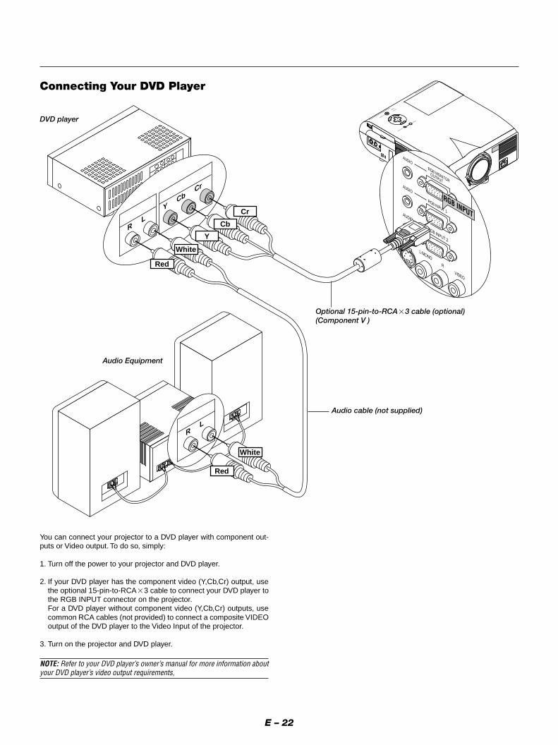
DVD player
Optional 15-pin-to-RCA�3 cable (optional)(Component V )
Audio cable (not supplied)
Audio Equipment
Connecting Your DVD Player
You can connect your projector to a DVD player with component out-puts or Video output. To do so, simply:
1. Turn off the power to your projector and DVD player.
2. If your DVD player has the component video (Y,Cb,Cr) output, usethe optional 15-pin-to-RCA�3 cable to connect your DVD player tothe RGB INPUT connector on the projector.For a DVD player without component video (Y,Cb,Cr) outputs, usecommon RCA cables (not provided) to connect a composite VIDEOoutput of the DVD player to the Video Input of the projector.
3. Turn on the projector and DVD player.
NOTE: Refer to your DVD player’s owner’s manual for more information aboutyour DVD player’s video output requirements,

E – 23
MENU
ENTER
CANCEL
SELECT
POWER STATUS
ON/STAND BY
SOURCE
AUTO ADJUST
AC IN
S-VIDEO
VIDEO
AUDIO
RGB INPUT 2
AUDIO
RGB INPUT 1
L/MONO
R
AUDIO
RGB MONITOR
OUTPUT
USB
PC-CARD
C CONTROLMOUSEOUT
REMOCONTRINPU
S-VIDEO
VIDEO
AUDIO
RGB INPUT 2
AUDIO
RGB INPUT 1
L/MONO
R
AUDIO
RGB MONITOR
OUTPUT
VIDEO
S-VIDEO
R L
R L
VIDEO
VCR/ Laser disc player
S-video cable (not supplied)
Audio equipment
Audio cable (not supplied)
Document camera
Video cable (not supplied)
Connecting Your VCR or Laser Disc Player
Use common RCA cables (not provided) to connect your VCR, laser disc player or document camera to your projector.To make these connections, simply:1. Turn off the power to the projector and VCR, laser disc player or document camera.
2. Connect one end of your RCA cable to the video output connector on the back of your VCR or laser disc player, connect the other end to the Videoinput on your projector. Use an audio cable (not supplied) to connect the audio from your VCR or laser disc player to your audio equipment (if yourVCR or laser disc player has this capability). Be careful to keep your right and left channel connections correct for stereo sound.
3. Turn on the projector and the VCR or laser disc player.
NOTE: Refer to your VCR or laser disc player owner’s manual for more information about your equipment’s video output requirements.

E – 24
About Startup screen(Menu Language Select screen)When you first turn on the projector, you will get the Startup screen.This screen gives you the opportunity to select one of the seven menulanguages: English, German, French, Itilan, Spanish,Swedish and Japa-nese.
To select a menu language, follow these steps:
1. Use the Select � or � button to select one of the seven languagesfor the menu.
2. Press the Enter button to execute the selection.
3. The Basic/Custom menu will be displayed in the language youhave selected.
To close the menu, press the Cancel button.
After this has been done, you can proceed to the advanced menu op-eration.If you want, you can select the menu language later. See “Language”on page E-35.

E – 25
3. OPERATIONThis section describes how to select a computer or video source, howto adjust the picture, and how to customize the menu or projector set-tings.
General ControlsBefore you turn on your projector, ensure that the computer or videosource is turned on and that your lens cap is removed.
1. Turn on the ProjectorPlug the supplied power cable in the wall outlet. The projectorwill go into its standby mode and the power indicator will gloworange.Only after you press the “On” button on the remote control (“ON/STAND BY” button on the projector cabinet) will the power indi-cator turn to green and the projector become ready to use.NOTE: To turn the projector on by plugging in the power cable, use themenu and enable the “Auto Start” feature. (See page E-37.)
2. Select the Computer, Video Source or PC Card ViewerPress a source button on the remote control or the projector cabi-net to select “Video” (VCR, document camera, or laser discplayer), S-Video”, “RGB 1 or 2” (computer or DVD with compo-nent output) or “PC Card Viewer” to display the image.Or press the “Menu” button on the remote control or the cabinetand use the menu to select your video source: “Video”, “S-Video”,“RGB1 or 2”, or “PC Card Viewer”.
3. Adjust the Image Size and the FocusUse the Zoom ring to adjust the image size, then use the Focusring to obtain the best focus.Use the “Magnify” button (+) or (-) on the remote control to makethe image larger up to 400%.
4. Turning off the ProjectorFirst press the “off” button on the remote control (“ON/STANDBY” button on the projector cabinet) for a minimum of two sec-onds. The power indicator will glow orange. Then, unplug thepower cable. The power indicator will go out.
IMPORTANT:• The projector should be unplugged if it will not to be used for an
extended period.• To turn off the image and sound briefly (five minutes or less), use
the “Picture Mute” button instead of turning the projector off and on.• The projector will display a black, blue image or logo if no input sig-
nal is present.• Do not turn the projector off and then immediately back on. The
projector needs to cool for a minute before it can be restarted.
After the projector turns off, the cooling fans keep operating for a fullminute.Do not disconnect the power cable during this time.
Using the MenusNOTE: The on-screen menu may not be displayed correctly while interlacedmotion video image is projected.
1. Press the “Menu” button on the remote control or projector cabi-net to display the Main Menu.NOTE: When using a USB mouse, click the mouse button to display themain menu. For other operations, do the same way as you use your PCmouse.
2. Press the �� buttons on the remote control or the projector cabi-net to highlight the menu for the item you want to adjust or set.
3. Press the � button or the “Enter” button on the projector cabinetor the “Left Click” button on the remote control to select a submenuor item.
4. Adjust the level or turn the selected item on or off by using “Se-lect” � or � buttons on the cabinet, or the “Mouse button” on theremote control. The on-screen slide bar will show you the amountof increase or decrease.
5. Changes are stored until you adjust it again.ENTER ......... Stores the setting or adjustments.CANCEL .......... Return to the previous screen without storing settings or ad-
justments.NOTE: You can close the main and sub menus simultaneously by pressingthe PJ button to cancel the Projector mode.
6. Repeat steps 2-5 to adjust an additional item, or press “Cancel”on the projector cabinet or the remote control to quit the menudisplay.
Using a USB MouseUsing a USB mouse gives you a smooth operation. A commerciallyavailable USB mouse is required.
NOTE: There may be some brands of USB mouse that the projector does notsupport.
Operate the Menus using the USB mouse:
Mouse Cursor:When connecting a USB mouse to the projector, you get a mousecursor on the screen.Unless you use your USB mouse within 10 seconds, the mousecursor disappears.
Menu Display:Clicking with a mouse button displays the main menu.Clicking displays the pull-down menu.To close the menu, click anywhere in the background.
Adjusting and Setting Display:You can select a menu item and click with a mouse button to makeadjustments and setting.
Examples:Click (or press and hold) the mouse button � or � to adjust thebrightness.Or click and drag the mouse button on the slide bar horizontally toadjust it.
To save the adjustments, click . The display is closed.If you click anywhere in the background while displaying adjust-ment and setting menu or dialog box, you will get the main menu atthe clicking point.
NOTE: The MOUSE OUTPUT port on the projector is not compatible with theUSB mouse.

E – 26
Source display
SOURCE AUTO ADJUST
Each time the Source button is pressed, the input source will changeas follows:→ RGB1 → RGB2 → Video → S-Video → PC Card Viewer
If no input signal is present, the input will be skipped.
Press the Auto Adjust button to fine-tune the computer image or toremove any vertical banding that might appear and to reduce videonoise, dot interference or cross talk (this is evident when part of yourimage appears to be shimmering). This function adjusts the clock fre-quencies that eliminate the horizontal banding in the image. This func-tion also adjusts the clock phase to reduce video noise, dot interfer-ence or cross talk. (This is evident when part of your image appears tobe shimmering.)This adjustment may be necessary when you connect your computerfor the first time.
NOTE: The Auto Adjust function does not work for component signal.
Basic OperationSelecting the computer or video source:
Adjust the Image Using Auto AdjustThe Auto Adjust function automatically optimizes the image in RGBmode.
VIDEO S-VIDEO AUTO ADJ.
RGB 1
MENU LASER
RGB 2 PJ
ONOFF
AUTO ADJUST
HELP POINTER PC CARD
AUTO ADJ.VIDEO S-VIDEO
RGB 1 RGB 2 PJ
[Poor picture]
[Normal picture]

E – 27
Volume control:Sound level from the speaker on the projector can be adjusted.
increase volumeVOL.
Volume bar
decrease volume
Turning off picture and sound:Press the Picture Mute button to turn off the image and sound for ashort period of time. Press again to restore the image and sound.
PIC-MUTE
Getting Help about how to operate the projector:You get the contents about Help.
Display Help
MENU LASER
R-CLICK /CANCEL
Exit Help
Using PointerYou can use one of eight pointers to draw your audience's attention tothe portion of a projected image you want.
Press the Pointer button todisplay the pointer.
Use the Select button tomove the pointer.
Enlarging and Moving a PictureYou can enlarge the area you want up to 400 percent.
To do so:1. Press the Pointer button to display the pointer.
2. Move the pointer to the area you want to enlarge.
3. Enlarge the selected area.When the Magnify (+) button is pressed, the pointer is changed toa magnifying glass. To move the magnifying glass, use the Mousebutton.
MAGNIFY
HELP
POINTER
POINTER

E – 28
Customizing Basic/Custom Menu
The Basic/Custom menu can be customized to meet your requirements.Selecting a menu item from the “Basic/Custom Menu Edit” list, allowsyou to custom tailor the menu items to your needs.
1. Select “Basic/Custom Menu Edit” to display the “Basic/CustomMenu Edit” screen.
2. Use the � or � button to highlight your selection and press theEnter button to place a check mark next to an option. This actionenables that feature.Press the Enter button again to clear the check box.
If you select an item with a solid triangle � and press the Enterbutton on the remote control or the projector cabinet, you canenable all the items within that submenu.Also you can turn on an item within the submenu without placinga check mark on the main menu item.NOTE: Up to 12 main menu items (within Basic/Custom Menu Edit, notincluding submenu items) can be selected.
4. Return the image to the original size.
Correcting Keystone distortionPress (+) or (-) to correct keystone (trapezoidal) distortion to make thetop or bottom of the screen longer or shorter so that the projectedimage is rectangular.
KEYSTONE
NOTE: The maximum keystone angle that can be corrected is 40 degrees up-ward and 20 degrees downward with the projector placed horizontally on theground plane.Depending on the type of graphics being used, the picture may get blurred orkeystone correction may not be possible when excessive keystone correctionis used.The idea is, the closer you are to native resolution, the better image you willsee.
Freezing a picturePress the Freeze button to freeze a picture. Press again to resumemotion.
Keystone distortion Normal
MAGNIFY
FREEZE

E – 29
3. In order for the changes to take effect, use the � or � button onthe remote control or the projector cabinet to highlight “OK”,then press the Enter button. To cancel the changes, use the � or� buttons to highlight “Cancel” and press the “Enter” button.To return to the factory default, select “Reset” then press the “En-ter” button.
The default Basic/Custom Menu items are:Source Select (RGB1/2, Video, S-Video and PC Card Viewer), Pic-ture, Volume, Image Options (Keystone, Color Temperature andLamp Mode), Projector Options (Menu and Setup), Tools (Capture,PC Card Files and ChalkBoard) and Help (Contents and Informa-tion)
NOTE: Once you have selected OK on the Basic/Custom Menu Edit screen, youcannot cancel the changes on the Menu screen. However, you can re-edit themenu items over again as described in the steps above.
NOTE: If the “Advanced Menu” item has been selected on the Menu mode, youget the “Confirmation Change Menu” upon completion of “Basic/Custom Menu”editing. In this case, selecting “Yes” then “Enter” will close all the menus andapply the changes from the Advanced menu to the Basic/Custom Menu. If youselect “No” then “Enter” functions, then all menu items will return to the Ad-vanced menu, but your changes will still be available within the “Basic/CustomMenu” selection. To display the previously tailored Basic/Custom Menu, select“Basic/Custom Menu” from the “Menu Mode”.
An item “To Advanced Menu” will be added to the bottom of the Basic/Custom Menu.Selecting this item and pressing the “Enter” button will display the “Ad-vanced Menu” features.

E – 30
Menu Tree
Advanced MenuSource Select RGB2
RGB1
Picture VideoVolume S-Video Brightness/Contrast/Color/Hue/SharpnessImage Options PC Card ViewerProjector Options Volume
High-Bright/EcoToolsHelp Keystone
Normal/Natural 1/Natural 2Color TemperatureLamp ModeGamma Correction
Aspect Ratio Normal/Zoom/Wide Zoom/Cinema
Advanced OptionsNoise Reduction Off/Low/Medium/High
Factory DefaultColor Matrix Select Color Matrix HDTV/SDTV
Select Color Matrix Type B-Y/R-Y,Cb/Cr,Pb/PrWhite Balance Brightness R/G/B, Contrast R/G/BPosition/Clock Horizontal/Vertical/Clock/PhaseResolution Auto/NativeVideo Filter On/Off
All Data/Current Signal
MenuSetup
Menu Mode (Advanced Menu, Basic/Custom Menu)Basic/Custom Menu EditLanguage (English/German/French/Italian/Spanish/Swedish/Japanese)Projector Pointer (Pointer 1-8)Source Display (On/Off)Direct Button Volume Bar (On/Off)
Keystone Bar (On/Off)Menu Display Time (Manual/Auto 5 sec/Auto 10 sec/Auto 30 sec)
Orientation (Desktop Front/Ceiling Rear/Desktop Rear/Ceiling Front)Background (Blue/Black/Logo)Mouse Button(Right Hand/Left Hand)Sensitivity(Fast/Medium/Slow)PC Card Viewer Options Show Folder List (On/Off)(Auto Play/Manual Play)Interval (5-300 sec)Capture Options (High Quality/Normal/High Compression)Signal Select RGB1 (Auto/RGB/Component)
RGB2 (Auto/RGB/Component)Video (Auto/NTSC3.58/NTSC4.43/PAL/PAL60/SECAM)S-Video (Auto/NTSC3.58/NTSC4.43/PAL/PAL60/SECAM)
Auto Adjust (RGB Only) (On/Off)Auto Start (On/Off)Power Management (On/Off)Power Off Confirmation (On/Off)Keystone Save (On/Off)Fan High Speed Mode (On/Off)Auto Mute for Built-in Speaker (On/Off)Clear Lamp Hour MeterRemote Sensor (Front/ Back/ Left/ Right)S-Video Mode Select (Off/S2)RGBOUT Terminal (Disable/ RGB1/ RGB2)Communication Speed(4800/9600/19200/38400)Default Source Select (Last/Auto/Select)
(RGB1/RGB2/Video/S-Video/PC Card Viewer)
CapturePC Card FilesChalkBoard
Contents ContentsInformation Page1 Source Name/Input Terminal/Horizontal Frequency/Vertical Frequency/Sync Polarity
Page2 Signal Type/Video Type/Sync Type/Interlace/ResolutionPage3 Aspect Ratio/Gamma Correction/Noise Reduction/Color Matrix/Matrix TypePage4 Lamp Remaining Time/Lamp Hour Meter/Projector Usage
Page 1
Page 2
Page 3
Page 4
Page 5
Page 6

E – 31
Menu windows or dialog boxes typically have the following elements:Title bar: Indicates the menu title.
Highlight: Indicates the selected menu or item.
Solid triangle: Indicates further choices are available. A highlighted triangle indicates the item is active.
Tab: Indicates a group of features in a dialog box. Selecting on any tab brings its page to the front.
Radio button: Use this round button to select an option in a dialog box.
Check box: Place a checkmark in the square box to turn the option On.
Slide bar: Indicates settings or the direction of adjustment.
OK button: Press to confirm your setting. You will return to the previous menu.
Cancel button: Press to cancel your setting. You will return to the previous menu.
Close button: Click to close the window with saving changes. (USB mouse only)
Help button: Indicates that help about that feature is available (USB mouse only). Press the Help button on the remote control to display help.
Toolbar: Contains several icons for specific tasks. It is also referred to as "launcher".
Drag: Point the mouse here, and click and drag to move a toolbar.
Menu Elements
Title barTab
Highlight
Help Button
Close Button
OK Button
Cancel Button
Solid triangle
Radio button
Slide bar
Check box
Drag
Tool bar

E – 32
The launcher is a tool bar including the following buttons:
Drag ............. Drags to move the tool bar. (for USB mouse operation only)Prev ............. Returns to the previous slide or folder.Next ............. Advances to the next slide or folder.Play .............. Plays back automatically or manually depending on the set-
ting on PC Card Viewer Options of the menu. This allows youto move on to the next slide when "Manual Play" is selected.
Stop ............. Stops Auto Play while you are playing back and to resumeplaying from the selected slide or folder when "Auto Play" isselected.
Jump ........... Displays a list of slides while you are playing back.Select ........... Displays a list of folders while you are playing back.Setup ........... Displays the PC Card Viewer Options dialog box on Page 2 of
the Setup dialog box.Delete ........... Deletes a captured slide(s) or all the captured slides in the
selected folder.View ............. Hides the tool bar while you are playing back. Clicking with
the right button of a mouse shows it again.
Picture (not available for PC Card Viewer)
Menu Descriptions & FunctionsSource Select
Enables you to select a video source such as a VCR, DVD player, laserdisc player, computer or document camera depending on what is con-nected to your inputs.Press the "Select" button on the projector cabinet or �� buttons onyour remote control to highlight the menu for the item you want to ad-just.
RGB1 / RGB2Selects the computer connected to your RGB or component signal.
NOTE: An optional component cable (Component V cable) is needed for a com-ponent signal. Select "Component" from the Input Signal submenu to displaythe component signal.
VideoSelects what is connected to your Video input-VCR, laser disc player,DVD player or document camera.
S-VideoSelects what is connected to your S-Video input-VCR, DVD player, orlaser disc player.
NOTE: A frame may freeze for a brief period of time when a video is played backin fast-forward or fast-rewind with a Video or S-Video source.
PC Card ViewerThis feature enables you to make presentations using a PC card that containscaptured images and slides created with the exclusive PC Card Viewer Utilitycontained in the CD-ROM. See page E-41 for installing the PC Card ViewerUtility. The starting screen for the PC Card Viewer varies depending on thesettings of the Setup's Page 2. See Setup on page E-36.
NOTE: Even if you switch the current PC Card Viewer source to another source,the current slide is retained. When you return back to the PC Card Viewer, youwill get the slide that has been retained. A launcher will appear when you pressthe MENU button.
A press of the MENU button displays the toolbar; a press of the MENUbutton again displays the Menu and hereafter each press of the MENUbutton switches displaying between the Menu and the toolbar.
Provides access to controls for your image. Use �� buttons on theprojector cabinet or the remote control to highlight the menu for theitem you want to adjust.
Brightness ... Adjusts the brightness level or the back raster intensity.Contrast ....... Adjusts the intensity of the image according to the incoming
signal.Color ............ Increases or decreases the color saturation level (not valid
for RGB).Hue .............. Varies the color level from +/- green to +/-blue. The red level
is used as reference. This adjustment is only valid for Videoand Component inputs (not valid for RGB).
Sharpness .... Controls the detail of the image for Video (Not valid for RGBand Component).
Volume (not available for PC Card Viewer)
Adjusts the sound level of the projector.
NOTE: You can also display the volume bar without opening the menu. See"Volume Bar (Direct Button)"on page E-35 for more details.
Drag
Prev Play Jump Setup View
Next Stop Select Delete
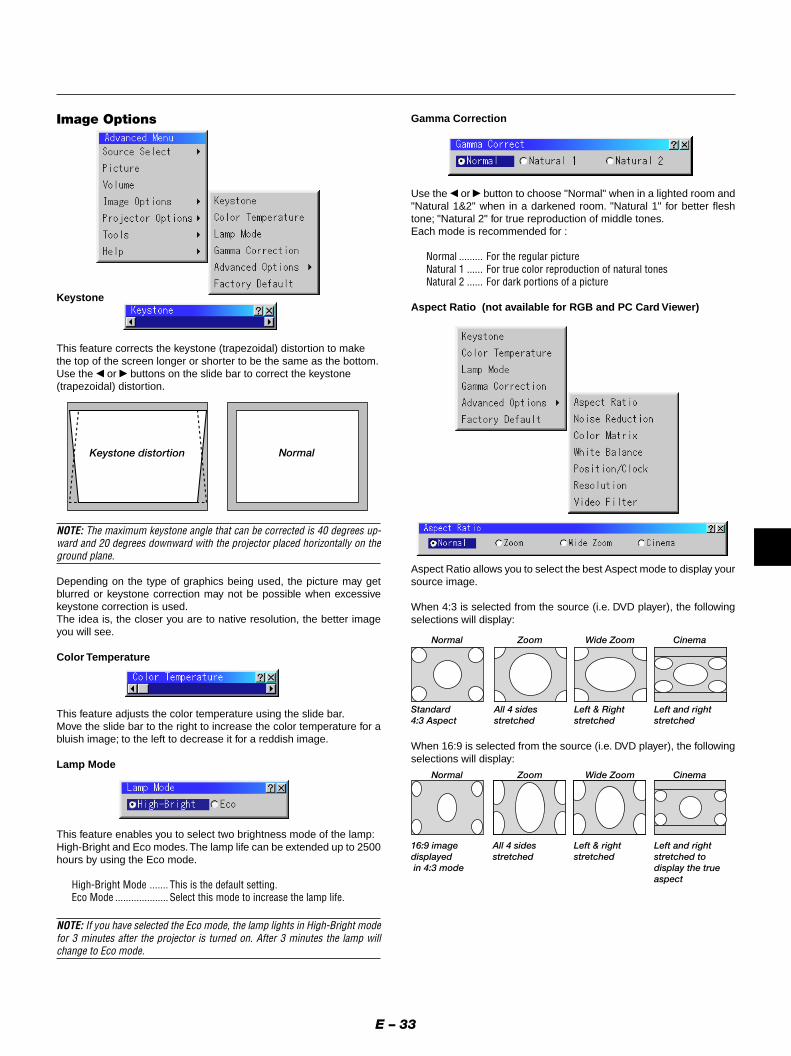
E – 33
Image Options
Keystone
This feature corrects the keystone (trapezoidal) distortion to makethe top of the screen longer or shorter to be the same as the bottom.Use the � or � buttons on the slide bar to correct the keystone(trapezoidal) distortion.
Keystone distortion Normal
NOTE: The maximum keystone angle that can be corrected is 40 degrees up-ward and 20 degrees downward with the projector placed horizontally on theground plane.
Depending on the type of graphics being used, the picture may getblurred or keystone correction may not be possible when excessivekeystone correction is used.The idea is, the closer you are to native resolution, the better imageyou will see.
Color Temperature
This feature adjusts the color temperature using the slide bar.Move the slide bar to the right to increase the color temperature for abluish image; to the left to decrease it for a reddish image.
Lamp Mode
Gamma Correction
Use the � or � button to choose "Normal" when in a lighted room and"Natural 1&2" when in a darkened room. "Natural 1" for better fleshtone; "Natural 2" for true reproduction of middle tones.Each mode is recommended for :
Normal ......... For the regular pictureNatural 1 ...... For true color reproduction of natural tonesNatural 2 ...... For dark portions of a picture
Aspect Ratio (not available for RGB and PC Card Viewer)
Aspect Ratio allows you to select the best Aspect mode to display yoursource image.
When 4:3 is selected from the source (i.e. DVD player), the followingselections will display:
Standard4:3 Aspect
All 4 sidesstretched
Left & Rightstretched
Left and rightstretched
16:9 imagedisplayed in 4:3 mode
All 4 sidesstretched
Normal Zoom Wide Zoom Cinema
Normal Zoom Wide Zoom Cinema
Left & rightstretched
Left and rightstretched todisplay the trueaspect
This feature enables you to select two brightness mode of the lamp:High-Bright and Eco modes. The lamp life can be extended up to 2500hours by using the Eco mode.
High-Bright Mode ....... This is the default setting.Eco Mode .................... Select this mode to increase the lamp life.
NOTE: If you have selected the Eco mode, the lamp lights in High-Bright modefor 3 minutes after the projector is turned on. After 3 minutes the lamp willchange to Eco mode.
When 16:9 is selected from the source (i.e. DVD player), the followingselections will display:

E – 34
Noise Reduction (not available for RGB and PC Card Viewer)
You can select three levels video noise reduction.
NOTE: The lower the Noise Reduction level, the better the image quality by wayof higher video bandwidth.
Color Matrix (available for component video signal only)
First select an appropriate color matrix to fit your component signal forHDTV or SDTV. Then select an appropriate matrix type from B-Y/R-Y,Cb/Cr or Pb/Pr.
White Balance
This allows you to adjust the white balance. Brightness for each color(RGB)is used to adjust the black level of the screen;Contrast for each color (RGB)to adjust the white level of the screen.First use the � or � buttons to select R, G, or B for the brightness andthe contrast. Next use the � or � buttons to adjust the level.
Position/ Clock (when Auto Adjust is off)
This allows you to manually adjust the image horizontally and verti-cally, and adjust Clock and Phase.
Horizontal/Vertical Position.................... Adjusts the image location horizontally and vertically using
the � and � buttons.This adjustment is made automatically when the Auto Adjustis turned on.
Clock ............ Use this item to fine tune the computer image or to removeany vertical banding that might appear. This function adjuststhe clock frequencies that eliminate the horizontal banding inthe image.Press the � and � buttons until the banding disappears.This adjustment may be necessary when you connect yourcomputer for the first time. This adjustment is made auto-matically when the Auto Adjust is turned on.
Phase ........... Use this item to adjust the clock phase or to reduce videonoise, dot interference or cross talk. (This is evident whenpart of your image appears to be shimmering.) Use the �and � buttons to adjust the image.
See "Auto Adjust (RGB Only) on page E-37 for turning on or off theAuto Adjust feature.Use "Phase" only after the "Clock" is complete.This adjustment is made automatically when the Auto Adjust is turnedon.
Resolution (when Auto Adjust is off)
This allows you to activate or deactivate the Advanced AccuBlend fea-ture.
Auto ............. Turns on the Advanced AccuBlend feature. The projector au-tomatically reduces or enlarges the current image to fit thefull screen.
Native ........... Turns off the Advanced AccuBlend feature. The projector dis-plays the current image in its true resolution.
See "Auto Adjust (RGB Only) on page E-37 for turning on or off theAuto Adjust feature.
NOTE: While you are displaying an image with higher resolution than theprojector's native resolution, even when you are in the Native mode, the imageis displayed full screen using the Advanced AccuBlend feature.
Video Filter (when Auto Adjust is off)
This function reduces video noise.
On ................ The low-pass filter is applied.Off ................ The filter is removed.
Screen adjustments are possible even when the filter is On.

E – 35
Factory Default
Changes all adjustments and setting to the factory preset for eachsource individually except Lamp Hour Meter, Projector Usage, Lan-guage and Communication Speed. (To reset the lamp usage time, see"Clear Lamp Hour Meter" on page E-37.)
All Data ............... Reset all the adjustments and settings for all the signalsto the factory preset.
Current Signal ..... Resets the adjustments for the current signal to the fac-tory preset levels.
The items that can be reset for the currently projected image are:Picture (Brightness, Contrast, Color, Hue and Sharpness) and ImageOptions (Color Temperature, Gamma Correction, Advanced Options[Aspect Ratio, Noise Reduction, Color Matrix, White Balance, Posi-tion/Clock, Resolution and Video Filter] ).
NOTE: The Volume, Keystone, Lamp Mode and all the items in the ProjectorOptions can be reset only when "All Data" is selected.
Projector Options
Allows you to set preferences for the on-screen menu.Press “OK” to save your changes for all the features.
Menu Mode:This feature allows you to select two menu modes: Advanced Menuand Basic/Custom Menu.
Advanced Menu .......... This is the menu that contains all the available menusand commands.
Basic/Custom Menu .... This is the menu that you can customize using theBasic/Custom Menu Edit to fit your needs.
The factory default Basic/Custom menu includes:Source Select (RGB1/2, Video, S-Video and PC Card Viewer), Picture,Volume, Image Options (Keystone, Color Temperatureand and Lamp Mode),Projector Options (Menu and Setup), Tools (Capture, PC Card Files andChalkBoad) and Help (Contents and Information). See page E-28 for in-structions about how to customize the Basic/Custom Menu.
Language:You can choose one of seven languages for on-screen instructions.The options are: English, German, French, Italian, Spanish, Swed-ish and Japanese.
Projector Pointer:This enables you to select from eight different Pointer icons for the"Pointer" button on your remote control.After moving your Pointer icon to the area you want on the screen,press the Magnify button on the remote control to enlarge the se-lected area on the screen. See page E-27 for more details.
NOTE: There may be cases where the Pointer function is not available (ex. anon-interlace signal at 15kHz such as video game.)
Source Display:You can turn on and off the information for input name such asVIDEO and RGB.When this option is on, the current input will be displayed each timeyou switch sources or turn on the projector.
Direct Button:Volume Bar: This option turns on or off the volume bar when you adjustthe sound volume using VOL+/– button on the remote control.
On ................ You can increase or decrease the sound volume with the vol-ume bar on screen.
Off ................ You can increase or decrease the sound volume without hav-ing to use the volume bar.
Keystone Bar: This option turns on or off the keystone bar when you ad-just the keystone using KEYSTONE +/– button on the remote control.
On ................ You can increase or decrease the level with the keystone baron screen.
Off ................ You can increase or decrease the level without having to usethe keystone bar.
Menu Display Time :This option allows you to select how long the projector waits afterthe last touch of a button to turn off the menu.The preset choices are "Manual", "Auto 5 sec", "Auto 10 sec", and"Auto 30 sec". The "Auto 10 sec" is the factory preset.
Manual ......... The menu can be turned off manually.Auto 5 sec .... The menu will automatically be turned off in 5 seconds if no
buttons are pressed within 5 seconds.Auto 10 sec .. The menu will automatically be turned off in 10 seconds if no
buttons are pressed within 10 seconds.Auto 30 sec .. The menu will automatically be turned off in 30 seconds if no
buttons are pressed within 30 seconds.
NOTE: If no buttons on the remote control are pressed within 10 seconds, thePJ button’s light goes out to indicate that you are in the Computer mode. Toenable the projector menu operation again, press the PJ button again to lightred.
Menu

E – 36
SetupEnables you to set operating options.Press "OK" to save your changes for all the features of Page1, Page2,Page3, Page 4, Page5 and Page6.
[Page1]
Orientation:This reorients your image for your type of projection.The options are: desktop front projection, ceiling rear projection,desktop rear projection, and ceiling front projection.
Background:Use this feature to display a blue/ black screen or logo when nosignal is available. The default background is blue. You can changethe logo screen using the PC Card Files feature. See page E-39.
Mouse Settings:This option lets you to change your USB mouse settings. The mousesettings feature is available for USB mouse only. Choose the set-tings you want:
Mouse Button ............. "Right Hand" or "Left Hand"Mouse Sensitivity ....... "Fast", "Medium" or "Slow"
[Page2] PC Card Viewer Options
Show Folder List:If this option is checked, when PC Card Viewer input is selected onthe projector, the folder lists will be displayed and allows you toselect the presentation from a PC card.
Auto Play:If this option is checked, any given slide will start to play automati-cally.
Auto Play Interval:You can specify interval time between 5 and 300 seconds.
NOTE: The Auto Play Interval time set on the PC Card Viewer Utility over-rides the one set here.
Manual Play:Views a slide manually when PC Card Viewer input is selected.
NOTE: The Auto Play and Manual Play options determine the behavior ofthe Play/Stop [ / ] icon on the Viewer toolbar.
NOTE: If you check "Auto Play" and select "PC Card Viewer" on the projector,the slides will automatically start to play back from any given slide.
Capture Options: (available for JPEG only)These options are used for the Capture function that you can selectfrom Tools. You have three options for JPEG compression quality:High quality, Normal and High Compression.
High Quality . Gives quality of JPEG a priority.Normal ......... Gives normal JPEG quality.High Compression Gives compression a priority.
[Page3] Signal Select
RGB1/2:Allows you to choose "RGB" for an RGB source such as a com-puter, or "Component" for a component video source such as aDVD player. Normally select "Auto" and the projector automaticallydetects a component signal. However there may be some compo-nent signals that the projector is unable to detect. If this is the case,select "Component".
VIDEO and S-VIDEO:This feature enables you to select composite video standards manu-ally. Normally select "Auto".Select the video standard from the pull-down menu.This must be done for Video and S-Video separately.

E – 37
[Page4]
Auto Adjust (RGB Only):When "Auto Adjust" is set to "On", the projector automatically de-termines the best resolution for the current RGB input signal toproject an image using NEC's Advanced AccuBlend Intelligent PixelBlending Technology.The image can be automatically adjusted for position and stability;"Horizontal Position", "Vertical Position", "Clock", "Phase", and"Resolution."
On ................ Automatically adjusts image "Horizontal Position", "VerticalPosition", "Clock", "Phase" and "Resolution".
Off ................ User can adjust the image display functions ("Horizontal Po-sition", "Vertical Position", "Clock", "Phase" and "Resolution")manually.
Auto Start:Turns the projector on automatically when the power cable is in-serted into an active power outlet. This eliminates the need to al-ways use the "Power" button on the remote control or projector cabi-net.
Power Management:When this option is on and there is no RGB input for five minutes ormore, the projector will automatically turn itself off.
Power Off Confirmation:This option determines whether a confirmation dialog for turning offthe projector will appear or not.
NOTE: When the confirmation message is displayed, you must be in theProjector mode to operate your projector using the remote control. If not,press the PJ button on the remote control to change your projector to theProjector mode. The button lights to indicate that you are in the Projectormode.
Keystone Save:This option enables you to save your current keystone settings.Saving your change once affects all sources. The changes are savedwhen you turn off the projector.
Fan High Speed Mode:This option allows you to select two modes for fan speed: high-speed mode and normal speed mode.When you wish to cool down the temperature inside the projectorquickly, check this box. This is convenient especially when the pro-jector is installed on the ceiling.
Auto Mute for Built-in Speaker:This option allows you to mute the built-in speakers automaticallywhen you connect an audio cable to the AUDIO OUT terminal.
Clear Lamp Hour Meter:Resets the lamp clock back to zero. Pressing this button appears aconfirmation dialog box. To reset the lamp usage hour, press "OK".
NOTE: The projector will turn off and go into standby mode after 1600 hours(up to 2600 hours in Eco mode) of service. If this happens, press the "Help"button on the remote control for ten seconds to reset the lamp clock backto zero. Do this only after replacing the lamp.
[Page5]
Remote Sensor:This option determines which remote sensors on the projector areenabled in wireless mode.The options are: front, rear, right, or left. All checked boxes indicatethat they can accept the infrared signal from the supplied remotecontrol.
S-Video Mode Select:This feature is used to select the S-Video signal detection mode.This allows identifying of the S-Video signals with different aspectratio (Zoom signal 16:9, Wide Zoom signal 4:3).
S2 ............... Identifies Zoom or Wide Zoom signal. OFF ............. Does not identify any S-video signal.
RGBOUT Terminal:This option allows you to determine which RGB source is outputfrom the RGBOUT terminal when the Video, S-Video or Viewersource is selected.
Disable ......... Neither RGB 1 nor RGB 2 is output from the RGBOUT termi-nal.
RGB 1 .......... The signal from RGB 1 is output from the RGBOUT terminal.RGB 2 .......... The signal from RGB 2 is output from the RGBOUT terminal.
NOTE: The AUDIO OUT mini jack outputs sound for the source that theprojector currently selects independently of setting "RGB OUT Terminal".

E – 38
[Page6]
Communication Speed:This feature sets the baud rate of the PC Control port (Mini DIN 8Pin).It supports data rates from 4800 to 38400 bps.The default is 38400 bps. Select the appropriate baud rate for yourequipment to be connected.
Default Source Select:You can set the projector to default to any one of its inputs eachtime the projector is turned on.
Last .............. Sets the projector to default to the previous or last activeinput each time the projector is turned on.
Auto ............. Searches for an active source in order of RGB1 → RGB2 →Video → S-Video → PC Card Viewer → RGB1 and displaysthe first found source.
Select ........... Displays the selected source input every time the projector isstarted up. Select an input from the pull-down menu.
Tools
Provides tools for capturing images, displaying files in a PC Card anddrawing.
NOTE: The "Capture" and "PC Card Files" features are required for a PC card.
Capture:Allows you to capture an image from a source that is currently be-ing displayed. The image is saved as JPEG in the PC card.When you select Capture from the menu, you will get a tool bar. Youcan capture an image directly using the tool bar when the menu isnot displayed.
The tool bar includes the following buttons:Drag ............. Drags to move the tool bar. (for USB mouse operation only)Capture ........ Captures an image and save it as a JPEG file in a PC card.Freeze .......... Freezes and unfreezes images.Exit ............... Exits the Capture function.
Unless a PC card is inserted into the PC Card slot of the projector,the Capture feature is not available.The "Card Error" display means that the free space of the PC cardis insufficient for saving images. Make more space available on thecard by erasing unwanted images with your PC. The number ofimages that can be captured depends on the size of the PC card.
NOTE: Be sure not to turn off the power or remove the PC card while cap-turing an image. Doing so could cause a loss of the data in the PC card ordamage to the card itself.
NOTE: Captured images with higher resolution than the projector's nativeresolution cannot be displayed correctly.
PC Card Files:Displays a list of all the files stored in the PC card so that you canselect a file you want to display. You can also sort files by file nameor date, or display the file.Although a list of all the files in the PC card is displayed, you canview files in idx, text, HTML, JPEG and BMP format only.Selecting BMP and JPEG files automatically switches to the PCCard Viewer source.
NOTE: When an image with a resolution of XGA (1024�768) or higher isprojected, the PC Card Files screen may not be correctly displayed.
Selecting "Execute" displays the file you selected.When you select a JPEG or BMP file and press the Enter button onthe remote or the cabinet, or “Execute” on the above, you will get atoolbar. This toolbar is used to return to the PC Card Files screen.
Drag
Return
Close
Drag ............. Drags to move the tool bar. (for USB mouse operation only)Return .......... Returns to the PC Card Files screen.Close ............ Close the toolbar.
Drag
Freeze
Exit
Capture

E – 39
Changing Background Logo:The Logo button allows you to select a background logo from graphicfiles on a PC card and change to it as the background logo.
NOTE: File size must be 64KB or less. Other file formats than JPEG andBMP are not available.
1. Use the � or � button to select a JPEG or BMP file for your back-ground logo.
2. Use the � and then � button to select “Logo”.
3. Press the Enter on the remote control or the cabinet. You will get theconfirmation dialog box.
4. Select “OK” and press the Enter button. This completes changing alogo for the background.
* Once you have changed the background from the NEC logo to another,you cannot return the logo to background even by using Factory De-fault. To do so, repeat the above steps. The NEC logo file is includedon the supplied CD-ROM (/logo/nec_b_x.jpg).
ChalkBoard: (available only when using with USB mouse)Provides the tool bar for producing freehand drawings.
Drag ............. Drags to move the tool bar. (for USB mouse operation only)Pen .............. Left-click and drag to draw. Left-click [�] or right-click the
pen icon to display the pen palette containing four lines ofdifferent thickness from which you can select a line you pre-fer by left-clicking.
Color ............ Selects a color. Left-click to display the color palette fromwhich you can select a color you prefer by left-clicking.
Eraser .......... Left-click and drag to erase part of a drawing. Left-click [�]or right-click the eraser icon to display the eraser palette con-taining four eraser of different thickness from which you canselect an eraser you prefer by left-clicking.
Clear ............ Left-click to clear the drawing completely from the ChalkBoardscreen.
View ............. Hides the tool bar by left-clicking. Right-clicking anywhereon the screen displays the ChalkBoard tool bar again.
Exit ............... Clears the complete drawing and exits the ChalkBoard.
NOTE:* The ChalkBoard feature is available only when a USB mouse is used. Free-
hand drawings cannot be saved or captured.* The menu is not available while you display the ChalkBoard screen.* The Capture function is not available on ChalkBoard screen.* Switching slides clears a drawing completely.
Help
Contents:Provides an online help about how to use the menus. An under-lined link means that you can move to an adjustment item directly.Selecting the underlined link and pressing ENTER moves to thecorresponding adjustment item.
NOTE: The Help Menu may not be displayed correctly when a UXGA signalis displayed.
Information:Displays the status of the current signal, and the lamp and the pro-jector usage hours.This dialog box has four pages.
The information included are as follows:
NOTE: The progress indicator shows the percentage of remaining bulb life. Thevalue informs you of the amount of lamp and projector usage respectively.
[Page 1]Source NameInput TerminalHorizontal FrequencyVertical FrequencySync Polarity
[Page 2]Signal TypeVideo TypeSync TypeInterlaceResolution
[Page 3]Aspect RatioGamma CorrectionNoise ReductionColor MatrixMatrix Type
[Page 4]Lamp Remaining Time (%)Lamp Hour Meter (H)Projector Usage (H)
Drag
Pen Eraser View
Exit
ClearColor
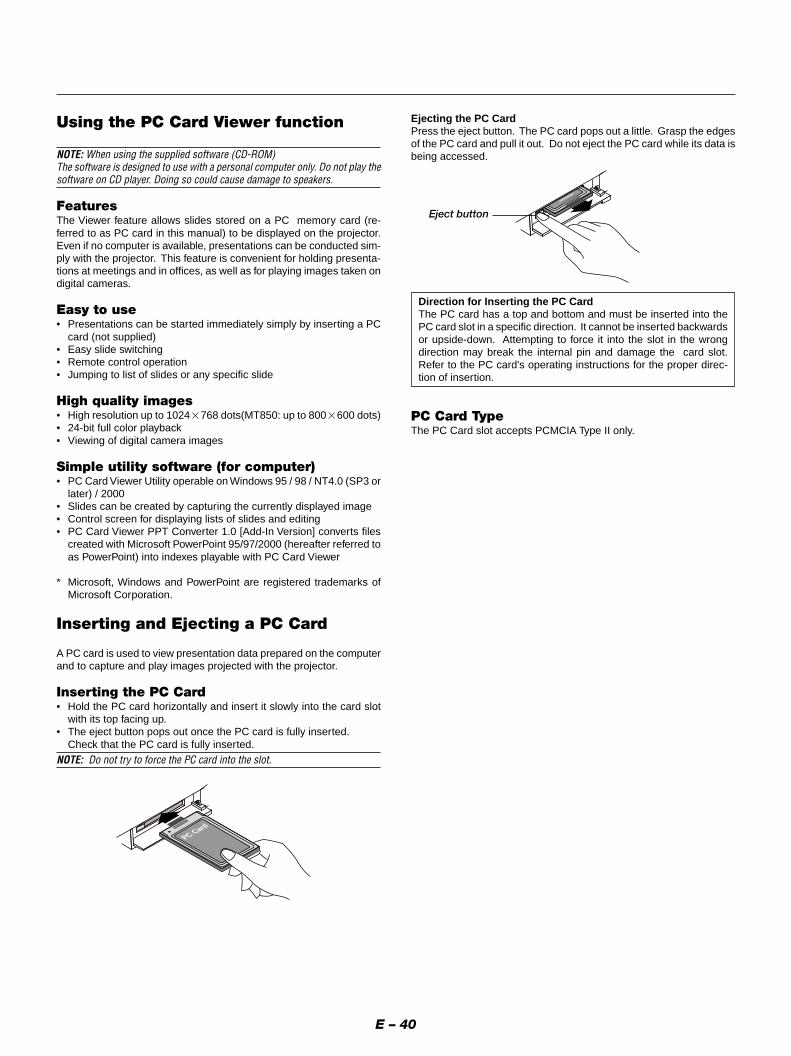
E – 40
Using the PC Card Viewer function
NOTE: When using the supplied software (CD-ROM)The software is designed to use with a personal computer only. Do not play thesoftware on CD player. Doing so could cause damage to speakers.
FeaturesThe Viewer feature allows slides stored on a PC memory card (re-ferred to as PC card in this manual) to be displayed on the projector.Even if no computer is available, presentations can be conducted sim-ply with the projector. This feature is convenient for holding presenta-tions at meetings and in offices, as well as for playing images taken ondigital cameras.
Easy to use• Presentations can be started immediately simply by inserting a PC
card (not supplied)• Easy slide switching• Remote control operation• Jumping to list of slides or any specific slide
High quality images• High resolution up to 1024�768 dots(MT850: up to 800�600 dots)• 24-bit full color playback• Viewing of digital camera images
Simple utility software (for computer)• PC Card Viewer Utility operable on Windows 95 / 98 / NT4.0 (SP3 or
later) / 2000• Slides can be created by capturing the currently displayed image• Control screen for displaying lists of slides and editing• PC Card Viewer PPT Converter 1.0 [Add-In Version] converts files
created with Microsoft PowerPoint 95/97/2000 (hereafter referred toas PowerPoint) into indexes playable with PC Card Viewer
* Microsoft, Windows and PowerPoint are registered trademarks ofMicrosoft Corporation.
Inserting and Ejecting a PC Card
A PC card is used to view presentation data prepared on the computerand to capture and play images projected with the projector.
Inserting the PC Card• Hold the PC card horizontally and insert it slowly into the card slot
with its top facing up.• The eject button pops out once the PC card is fully inserted.
Check that the PC card is fully inserted.
NOTE: Do not try to force the PC card into the slot.
PC Card
Ejecting the PC CardPress the eject button. The PC card pops out a little. Grasp the edgesof the PC card and pull it out. Do not eject the PC card while its data isbeing accessed.
Eject button
Direction for Inserting the PC CardThe PC card has a top and bottom and must be inserted into thePC card slot in a specific direction. It cannot be inserted backwardsor upside-down. Attempting to force it into the slot in the wrongdirection may break the internal pin and damage the card slot.Refer to the PC card's operating instructions for the proper direc-tion of insertion.
PC Card TypeThe PC Card slot accepts PCMCIA Type II only.

E – 41
Installing the PC Card Viewer Software
Before InstallingPerform the following before installing the PC Card Viewer software:• If Windows is already started, exit all applications. Installation may
not be performed properly if any applications are running.
InstallationInstall the viewer software as described below.To quit installation before it is completed, press the "Cancel" buttonthen follow the instructions in the dialog box.
1. Start up Windows.
2. Insert the CD-ROM into the CD-ROM drive.The auto CD play function automatically starts the CD-ROM'sprogram and the contents screen appears.
* The auto CD play function operates if the "Auto insert notification" box inthe computer's CD-ROM control panel is checked. (The box is checkedby default.)
3. Click [Installing the PC Card Viewer Utility 1.0]The setup dialog appears.
* Follow the instructions in the setup dialog to complete the installation.
For instructions on uninstalling the PC Card Viewer software, see pageE-45.
Starting Up the PC Card Viewer Softwareon your PC(PC Card Viewer Utility 1.0)
Use the PC Card Viewer Utility 1.0 for creating viewer slides.To start the PC Card Viewer software:* Select [Start]-[Programs]-[NEC Projector Tools]-[PC Card Viewer
Utility 1.0].
Refer to online help for instructions on using the PC Card Viewer soft-ware.
Contents of the English version PC Card Viewer software(PC Card Viewer Utility 1.0)This is the software used for creating PC Card Viewer slides. In thismanual it is referred to as the "PC Card Viewer software".
PC Card Viewer PPT Converter 1.0This is an application that converts files created with MicrosoftPowerPoint 95/97/2000 into indexes so that they can be played directlywith the PC Card Viewer Utility 1.0.PC Card Viewer PPT Converter is installed automatically when youinstall the PC Card Viewer Utility.To start PC Card Viewer PPT Converter:* Select PC Card Viewer PPT Converter from NEC Projector Tools.
Basic Operation of the PC Card Viewer SoftwarePC Card Viewer Utility is an application for editing documents, con-verting them into slides and storing them on PC cards as playbackdata (indexes) for presentations using projectors.

E – 42
Operating the PC Card Viewer Functionfrom the Projector (playback)
This section describes the operation for showing slides of presentationdocuments created using the PC Card Viewer function with the projec-tor.It is also possible to make slides directly from the images projectedwith the projector.
Projecting slides
1. Insert a PC card into the card slot.Insert the PC card with the side with the insertion direction arrowon the top.
* Press the eject button to eject the card.
2. Select the “PC Card Viewer” from the Source Select menu.
3. Project slides.
Checking “Show Folder List”, means that selecting PC Card Viewerinput displays a list of the folders in the PC card and if “Auto Play” ischecked the projector automatically starts to play slides at the firstslide of the folder you have selected.A tool bar will appear when you press the MENU button on the remotecontrol or the projector cabinet or clicking with the right button of amouse.
Drag
Prev Play Jump Setup View
Next Stop Select Delete
The tool bar includes the following buttons:
Drag .......... Drags to move the tool bar (for USB mouse operation only).
Prev .......... Returns to the previous slide or folder. Or this lets you playslides back in reverse.
Next .......... Advances to the next slide or folder. Or this lets you playslides back.
Play ........... Plays back automatically or manually depending on the set-ting on PC Card Viewer Options of the menu. This allows youto move on to the next slide when “Manual Play” is selected.
Stop .......... This allows you to stop Auto Play while you are playing backand to resume playing from the selected slide or folder when“Auto Play” is selected.
Jump ......... Displays a list of slides while you are playing back.
Select ........ Displays a list of folders while you are playing back.
Setup ........ Displays the PC Card Viewer Options dialog box on Page 2 ofthe Setup dialog box.
Delete ........ Deletes a captured slide(s) or all the captured slides in theCapture – specific folder.
View .......... Hides the tool bar while you are playing back. Pressing theMENU button or clicking with the right button of a mouseshows it again.
NOTE: If no PC card is inserted in the PC CARD slot, there is no signal, and ablack, blue or logo background is displayed, depending on the setting.
Playback is stopped when SLIDE +/– on the remote control or � / �button on the cabinet is pressed in Auto Play mode.
NOTE: Up to 12 indexes can be displayed on the list of folders. The folder in theright bottom is always a folder exclusively for captured images, but is onlydisplayed when images have been captured. To display the list of folders whenthere are 13 or more indexes stored on the PC card, select "Edit index" from thePC Card Viewer software's "File" menu and move the index you want to displayto within 12 indexes from the top of the folder index. For details on indexes,refer to the PC Card Viewer software's help folder.
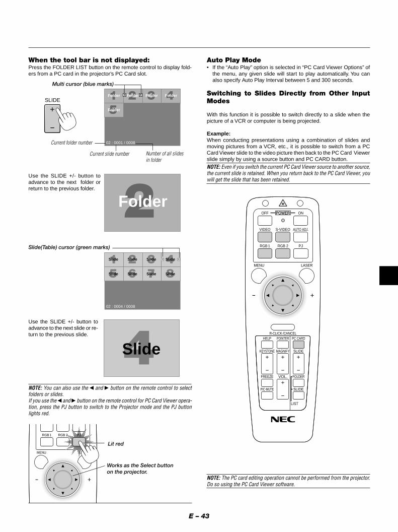
E – 43
When the tool bar is not displayed:Press the FOLDER LIST button on the remote control to display fold-ers from a PC card in the projector’s PC Card slot.
Use the SLIDE +/- button toadvance to the next folder orreturn to the previous folder.
Folder
02 : 0001 / 0008
Folder Folder Folder
Folder
Slide Slide Slide Slide
Slide Slide Slide Slide
02 : 0004 / 0008
Slide
Slide(Table) cursor (green marks)
Use the SLIDE +/- button toadvance to the next slide or re-turn to the previous slide.
Auto Play Mode• If the “Auto Play” option is selected in “PC Card Viewer Options” of
the menu, any given slide will start to play automatically. You canalso specify Auto Play Interval between 5 and 300 seconds.
Switching to Slides Directly from Other InputModes
With this function it is possible to switch directly to a slide when thepicture of a VCR or computer is being projected.
Example:When conducting presentations using a combination of slides andmoving pictures from a VCR, etc., it is possible to switch from a PCCard Viewer slide to the video picture then back to the PC Card Viewerslide simply by using a source button and PC CARD button.
NOTE: Even if you switch the current PC Card Viewer source to another source,the current slide is retained. When you return back to the PC Card Viewer, youwill get the slide that has been retained.
NOTE: The PC card editing operation cannot be performed from the projector.Do so using the PC Card Viewer software.
Folder
Lit red
Works as the Select buttonon the projector.
RGB 1
MENU LASER
RGB 2 PJ
Multi cursor (blue marks)
SLIDE
NOTE: You can also use the � and � button on the remote control to selectfolders or slides.If you use the � and � button on the remote control for PC Card Viewer opera-tion, press the PJ button to switch to the Projector mode and the PJ buttonlights red.
KEYSTONE
FREEZE
PIC-MUTE
HELP POINTER PC CARD
VIDEO S-VIDEO AUTO ADJ.
RGB 1
MENU LASER
R-CLICK /CANCEL
RGB 2 PJ
ONOFF
MAGNIFY
VOL.
SLIDE
FOLDER
SLIDE
LIST
Current folder number
Current slide number Number of all slidesin folder
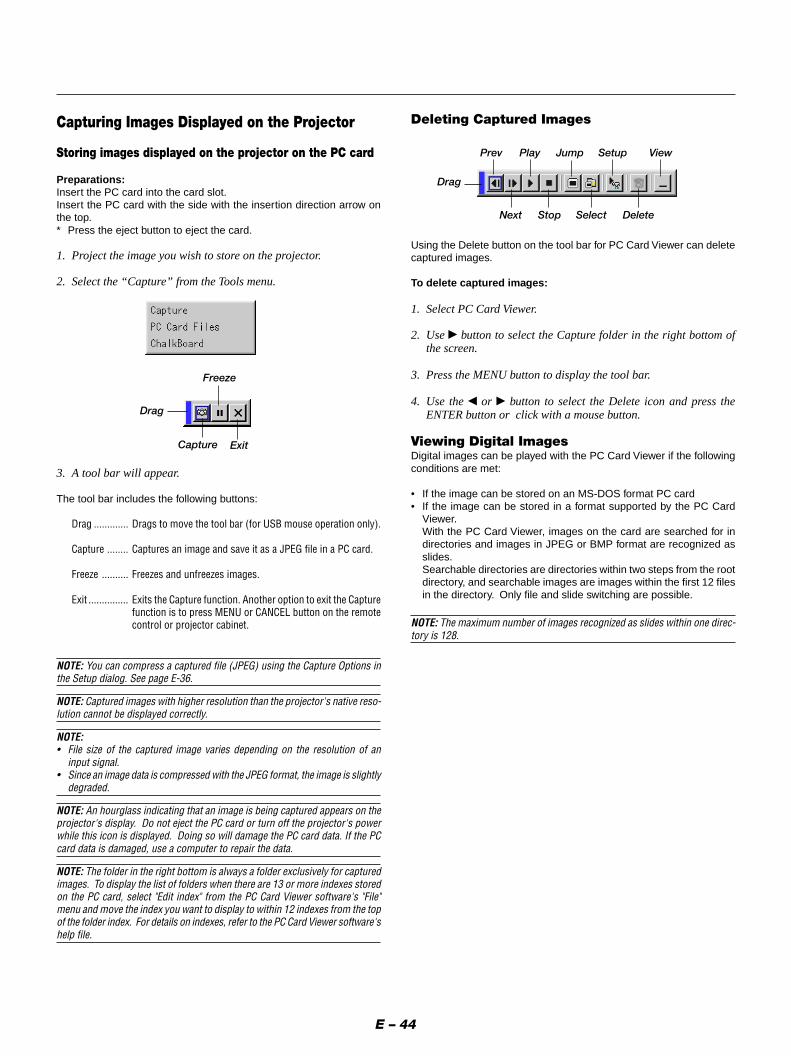
E – 44
Capturing Images Displayed on the Projector
Storing images displayed on the projector on the PC card
Preparations:Insert the PC card into the card slot.Insert the PC card with the side with the insertion direction arrow onthe top.* Press the eject button to eject the card.
1. Project the image you wish to store on the projector.
2. Select the “Capture” from the Tools menu.
3. A tool bar will appear.
The tool bar includes the following buttons:
Drag ............. Drags to move the tool bar (for USB mouse operation only).
Capture ........ Captures an image and save it as a JPEG file in a PC card.
Freeze .......... Freezes and unfreezes images.
Exit ............... Exits the Capture function. Another option to exit the Capturefunction is to press MENU or CANCEL button on the remotecontrol or projector cabinet.
NOTE: You can compress a captured file (JPEG) using the Capture Options inthe Setup dialog. See page E-36.
NOTE: Captured images with higher resolution than the projector's native reso-lution cannot be displayed correctly.
NOTE:• File size of the captured image varies depending on the resolution of an
input signal.• Since an image data is compressed with the JPEG format, the image is slightly
degraded.
NOTE: An hourglass indicating that an image is being captured appears on theprojector's display. Do not eject the PC card or turn off the projector's powerwhile this icon is displayed. Doing so will damage the PC card data. If the PCcard data is damaged, use a computer to repair the data.
NOTE: The folder in the right bottom is always a folder exclusively for capturedimages. To display the list of folders when there are 13 or more indexes storedon the PC card, select "Edit index" from the PC Card Viewer software's "File"menu and move the index you want to display to within 12 indexes from the topof the folder index. For details on indexes, refer to the PC Card Viewer software'shelp file.
Drag
Freeze
Capture Exit
Drag
Prev Play Jump Setup View
Next Stop Select Delete
Deleting Captured Images
Using the Delete button on the tool bar for PC Card Viewer can deletecaptured images.
To delete captured images:
1. Select PC Card Viewer.
2. Use � button to select the Capture folder in the right bottom ofthe screen.
3. Press the MENU button to display the tool bar.
4. Use the � or � button to select the Delete icon and press theENTER button or click with a mouse button.
Viewing Digital ImagesDigital images can be played with the PC Card Viewer if the followingconditions are met:
• If the image can be stored on an MS-DOS format PC card• If the image can be stored in a format supported by the PC Card
Viewer.With the PC Card Viewer, images on the card are searched for indirectories and images in JPEG or BMP format are recognized asslides.Searchable directories are directories within two steps from the rootdirectory, and searchable images are images within the first 12 filesin the directory. Only file and slide switching are possible.
NOTE: The maximum number of images recognized as slides within one direc-tory is 128.

E – 45
Uninstalling the PC Card Viewer Software
Even if you do now know the PC Card Viewer software's file names orwhere they are stored, the PC Card Viewer software files can be easilyremoved from the system using the "Install/Uninstall Applications" con-trol panel in Windows. (Normally there is no need to perform this op-eration.)
Uninstalling the softwareUse the procedure described below to uninstall the PC Card Viewersoftware files.
1. From the "Start" menu, select "Settings" then "Control Panels".
2. In the "Control Panels" dialog box, double-click on "Add/RemovePrograms".
3. In the "Add/Remove Programs Properties" dialog box, click the"Setup/Remove" tab, then select "PC Card Viewer Utility 1.0" fromthe list of applications and click on "Add/Remove".
4. In the "Confirm File Deletion" dialog box, click "Yes".
5. Once the application is uninstalled, click on "OK" in the "RemoveProgram From Your Computer" dialog box.

E – 46
Terminology
PC card
ATA card
CompactFlash
TYPE (I, II and III)
BMP
JPEG
This is the name of a card currently being standardized by the Japan Electronic Industry Association (JEIDA) and PCMCIA(Personal Computer Memory Card Interface Association) of the United States.
A type of PC card. ATA was originally a type of interface between computers and fixed disk devices. The ATA card is a standardcard-type recording medium.
CompactFlash card is a small removable card conforming to ATA specifications. It is one-fourth the volume of a PCMCIA card.
PCMCIA 2.1 PC cards are divided into three types according to their thickness: Type I (3.3 mm), Type II (5.0 mm) and Type III(10.5 mm).
A type of image format. The standard Windows Bit Map format used for MS-DOS/Windows-compatible computers.
A type of image format. "JPEG" is the abbreviation of Joint Photographic Experts Group. JPEG compression offers efficientdata storage. The data not required for displaying the image is identified and deleted. Since the data is deleted, JPEGalgorithms are said to be irreversible. This means that once the image is compressed, the decompressed image it is not thesame as the original image.

E – 47
This section describes the simple maintenance procedures you shouldfollow to replace the lamp and clean the filter.
Replacing the LampAfter your lamp has been operating for 1500 hours (2500 hours : Ecomode) or longer, the “Status” light in the cabinet will go on and themessage will appear. Even though the lamp may still be working, re-place it at 1500 (2500 hours : Eco mode) hours to maintain optimalprojector performance.
CAUTION• DO NOT TOUCH THE LAMP immediately after it has been used. It will
be extremely hot. Turn the projector off, wait a full minute, and thendisconnect the power cable. Allow at least one hour for the lamp tocool before handling.
• DO NOT REMOVE ANY SCREWS except the lamp cover screw and twolamp housing screws. You could receive an electric shock.
• The projector will turn off and go into stand by mode after 1600 (2600hours : Eco mode) hours of service. If this happens, be sure to replacethe lamp. If you continue to use the lamp after 1500 hours (2500 hours: Eco mode) of use, the lamp bulb may shatter, and pieces of glass maybe scattered in the lamp housing. Do not touch them as the pieces ofglass may cause injury. If this happens, contact your NEC dealer forlamp replacement.
To replace the lamp:1. Loosen the lamp cover screw until the screwdriver goes into a
freewheeling condition and remove the lamp cover. The lamp coverscrew is not removable.
4. MAINTENANCE
ENTER
CANCEL
SELECT
POWERSTATUS
S
ON/STAND BY
MENU
SOURCE
AUTO
2. Loosen the two screws securing the lamp housing until the screw-driver goes into a freewheeling condition. The two screws are notremovable.Remove the lamp housing by pulling out the handle.NOTE: There is an interlock on this case to prevent the risk of electricalshock. Do not attempt to circumvent this interlock.
MENU
ENTER
CANCEL
SELECT
POWERSTATUS
SOURCE
AUTO ADJUST
ON/STAND BY
MENU
ENTER
SELECT
POWSTATUS
SOURCE
AUTO ADJUST
3. Insert a new lamp housing until the lamp housing is plugged intothe socket.CAUTION: Do not use a lamp other than the NEC replacement lamp(MT50LP). Order this from your NEC dealer.
Secure it in place with the two screws.Be sure to tighten the screws.
MENU
ENTER
CANCEL
SELECT
POWERSTATUS
ON/OFF
SOURCE
AUTO ADJUST
MENU
ENTER
CANCEL
SELECT
POWERSTATUS
SOURCE
AUTO ADJUST
4. Reattach the lamp cover.
Tighten the lamp cover screw.Be sure to tighten the screw.
ENTER
CANCSE
POWERSTATUS
ON/STAND BY
5. After you install a new lamp, select [Menu] → [Projector Op-tions] → [Setup]→[Page 4]→[Clear Lamp Hour Meter] to resetthe lamp usage hours.
NOTE: When the lamp exceeds 1600 hours (2600 hours : Eco mode) of ser-vice, the projector cannot turn on and the message is not displayed. If thishappens, press the OFF or Help button on the remote control for a minimum of10 seconds while in standby mode. When the lamp time clock is reset to zero,the STATUS indicator goes out.

E – 48
Cleaning or Replacing the FiltersThe air-filter sponge keeps the inside of the MultiSync MT1055/MT1050/MT850 Projector free from dust or dirt and should be cleaned afterevery 100 hours of operation (more often in dusty conditions). If thefilter is dirty or clogged, your projector may overheat.
CAUTION• Turn off the power and unplug the projector before replacing the filter.• Only clean the outside of the filter cover with a vacuum cleaner.• Do not attempt to operate the projector without a filter cover.• Your projector will not operate unless the filter cover is installed cor-
rectly.
To clean the air-filter:Vacuum the filter-through the filter cover.
MENU
ENTER
CANCEL
SELECT
POWER STATUS
ON/OFF
SOURCE
AUTO ADJUST
USB
AC IN
To replace the air-filter:
1. Remove the filter cover by pushing up on the catch of the coveruntil you feel it detach.
MENU
EL
LECT SOURCE
AUTO ADJUST
USB
AC IN
12
2. Reinstall the new filter cover.NOTE: Do not detach the sponge from the filter cover. Do not wash the filtercover with soap and water. Soap and water will damage the the filter mem-brane. Before replacing the filter cover, remove dust and dirt from the pro-jector cabinet. Keep out dust and during filter replacement.
AC IN
1
2

E – 49
5. TROUBLESHOOTINGThis section helps you resolve problems you may encounter while setting up or using the projector.
Standby
Cooling down
Lamp in High-Bright mode
Lamp in Eco mode
3 minutes after lamp is turned on inEco mode
Lamp has reached its end of life(1500 hours or over)
Lamp life has reached its end of life(1600 hours or over)
Lamp or filter cover error (3 locations)
Temperature error
Fan error
Lamp error
Power/ Status Light Messages
Common Problems & Solutions
Condition
Does not turn on
No picture
Image isn’t square to thescreen
Picture is blurred
Image is scrolling vertically,horizontally or both
Remote control does notwork
Status indicator is lit or blink-ing
Cross color in RGB mode
• Check that the power cable is plugged in and that the power button on the projector cabinet or the remotecontrol is on.
• Ensure that the lamp cover is installed correctly. See page E-47.• Check to see if the projector has overheated or the lamp usage exceeds 1600 hours (2600 hours in Eco
mode). If there is insufficient ventilation around the projector or if the room where you’re presenting is particu-larly warm, move the projector to a cooler location.
• Use the menu to select your source (Video, S-Video, RGB1, RGB2 or PC Card Viewer). See page E-32.• Ensure your cables are connected properly.• Use menus to adjust the brightness and contrast. See page E-32.• Remove the lens cap.• Reset the settings or adjustments to factory preset levels using the Factory Default on the Image Options
Menu in Advanced menu. See page E-35.
• Reposition the projector to improve its angle to the screen. See page E-14.• Use the Keystone to correct the trapezoid distortion. See page E-28 or 33.
• Adjust the focus. See page E-25.• Reposition the projector to improve its angle to the screen. See page E-14.• Ensure that the distance between the projector and screen is within the adjustment range of the lens. See
page E-17.
• Use menus or a source button on the remote control or the cabinet to select the source you want to input.
• Install new batteries. See page E-12.• Make sure there are no obstacles between you and the projector.• Stand within 22 feet (7 m) of the projector. See page E-12.• Make sure that you are in the Projector mode or the PJ button lights in red. If not, press the PJ button.
• See the Power/ Status Light messages above.
• If Auto Adjust is off, turn it on. If Auto Adjust is on, turn it off and balance the image with the Position and ClockAdjust on the Advanced Options Menu. See page E-34.
Problem Check These Items
Steady orange
Blinking green
Steady green
Steady green
Steady green
Steady green
Steady orange
Steady orange
Steady orange
Steady orange
Steady orange
–
–
–
Steady green
Blinking green
Steady red (High-Bright mode)/Steady orange (Eco mode)
Steady red
Blinking red (1 sec interval)
Blinking red (4 sec interval)
Blinking red (8 sec interval)
Blinking red (12 sec interval)
–
Blinks green for 60 seconds
–
–
Fixed at High-Bright mode. Lamp modecan be changed on the menu
Message appears on screen during 1500-1600 hours of lamp usage. The projectorreaches its end of life. Please replace thelamp as soon as possible.
The projector is in standby mode and can-not be turned on.
The projector is in standby mode and can-not be turned on.
The projector is in standby mode and can-not be turned on.
The projector is in standby mode and can-not be turned on.
The projector is in standby mode and can-not be turned on.
Power Indicator Status Indicator Note

E – 50
• Is “PC Card Viewer” selected from the Source menu?• Is the PC card seated in the PC CARD slot completely?• Are slide data stored in the PC card?• Have the contents of the PC card been destroyed?
• While an image with over 1024�768 dots (MT850: 800�600 dots) is projected, several lines of informationwill be lost. Use the supplied software change the image to 1024�768 dots in size.
• Use a computer, etc., to repair the data.
Condition Status
When using the PC Card Viewer function
For more information contact your dealer.
No picture
Part of a slide is not displayed
Contents of PC Card aredamaged

E – 51
6. SPECIFICATIONSThis section provides technical information about the MultiSync MT1055/MT1050/MT850 Projector’s performance.
Model Number MT1055/MT1050/MT850
OpticalLCD Panel 1.3” p-Si TFT active-matrix, 800�600 dots (MT850) / 1024�768 dots (MT1055/MT1050)
1.3” p-Si TFT active-matrix with Micro Lens Array (MT1055)
Lens Manual zoom, manual focus
MT1050/MT850 : F2.3 – 2.7 f=48.6 – 58.4 mm
MT1055 : F1.8 – 2.2 f=49.3 – 59.3 mm
Lamp 200W NSH lamp (160W in Eco mode)
The lamp, under normal operating conditions, is warranted for 1500 hours of operation time within 6 months.
Image Size 30 – 300 inches (762 – 7620 mm) diagonal
Projection Distance MT1050/MT850 : 4.3 – 36.7 ft (1.3 - 11.2 m)
MT1055 : 4.3 – 37.1 ft (1.3 - 11.3 m)
ElectricalInputs Video (NTSC / PAL / PAL60 / SECAM / NTSC4.43)
Horizontal Frequency : 15 – 100 kHz (RGB : 24 kHz or over)
Vertical Frequency : 50 – 120 Hz
Video Bandwidth RGB: 80 MHz
Color Reproduction Full color, 16.7 million colors simultaneously.
Horizontal Resolution 550 TV lines : NTSC / PAL / NTSC4.43 / YCbCr
350 TV lines : SECAM
RGB MT850 : 800 dots horizontal, 600 dots vertical
MT1055/MT1050 : 1024 dots horizontal, 768 dots vertical
Power Requirement 100 – 120 / 200 – 240 VAC, 50 / 60 Hz
Input Current 3.5 A (100 – 120 VAC) / 1.7A (200 – 240 VAC)
MechanicalDimensions MT1050/MT850 : 11.1" (W)�4.8" (H)�14.3" (D) / 281mm (W)�121mm (H)�364mm (D) (not including lens and feet)
MT1055 : 11.1" (W)�4.8" (H)�14.9" (D) / 281mm (W)�121mm (H)�376mm (D) (not including lens and feet)
Net Weight MT1050/MT850 : 13.0 lbs / 5.9 kg
MT1055 : 13.3 lbs / 6.0 kg
Environmental Considerations Operational Temperatures: 32˚ – 104˚F (0˚ to 40˚C), 20 – 80% humidity
Storage Temperatures: 14˚ – 122˚F (-10˚ to 50˚C), 20 – 80% humidity
Regulations UL Approved (UL 1950, CSA 950)
Meets DOC Canada Class B requirements
Meets FCC Class B requirements
Meets AS/NZS3548 Class B
Meets EMC Directive (EN55022, EN55024, EN61000-3-2, EN61000-3-3)
Meets Low Voltage Directive (EN60950, TUV GS Approved)
LCD panels are inherently susceptible to bad pixels.The LCD panel may have pixel failures at the rate of 0.01% or less.
We provide information about our projectors through the World Wide Web at http://www.nec-pj.com/
The specifications are subject to change without notice.

E – 52
Cabinet Dimensions
Unit = mm (inch)
MT1055
MENU
ENTERCANCEL
SELECT
POWER
STATUSON/STAND BY
SOURCEAUTO ADJUST
AC IN
US
B
S-VIDEOVIDEO
AUDIORG
B INPUT 2
AUDIORG
B INPUT 1
L/M
ONO
R
PC
-CA
RD
AUDIORG
B MO
NITOR
OUTPUT
1.5(0.06")281(11.06")
73.
5(2
.89"
)
121
(4.7
6")
4(0
.16"
)7.
5 (0
.3")
39.5(1.56")
376
(14.
9")
PC CONTRO
LM
OUSE
OUTPUT
REMO
TECO
NTROL
INPUT
Lens center
Lens center
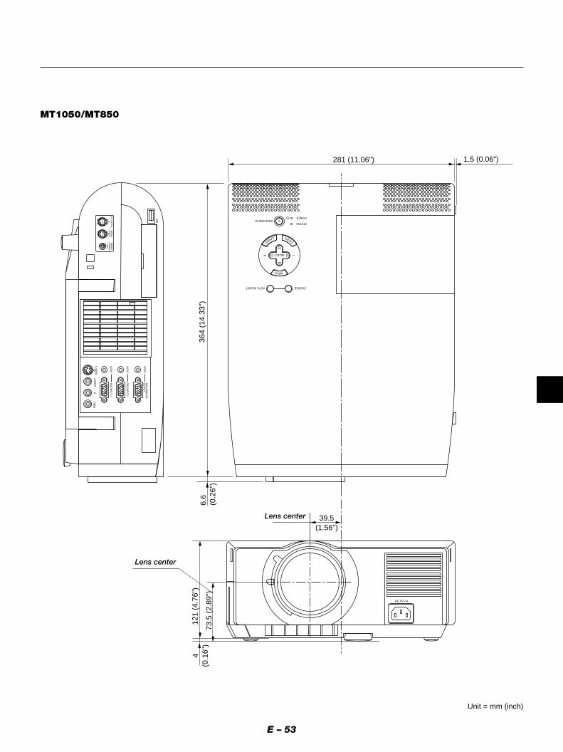
E – 53
Unit = mm (inch)
MT1050/MT850
MENU
ENTERCANCEL
SELECT
POWER
STATUS
SOURCEAUTO ADJUST
AC IN
USB
S-VIDEOVIDEO
AUDIORG
B INPUT 2
AUDIORG
B INPUT 1
L/M
ONO
R
AUDIORG
B MO
NITOR
OUTPUT
1.5 (0.06")281 (11.06")
73.
5 (2
.89"
)
121
(4.
76")
4(0
.16"
)6.
6(0
.26"
)36
4 (1
4.33
")
39.5(1.56")
ON/STAND BY
PC CONTRO
LM
OUSE
OUTPUT
REMO
TECO
NTROL
INPUT
Lens center
Lens center

E – 54
D-Sub Pin AssignmentsMini D-Sub 15 Pin Connector
Pin No. RGB Signal (Analog) YCbCr Signal
1 Red Cr
2 Green or Sync on Green Y
3 Blue Cb
4 Ground
5 Ground
6 Red Ground Cr Ground
7 Green Ground Y Ground
8 Blue Ground Cb Ground
9 No Connection
10 Sync Signal Ground
11 Ground
12 Bi-directional DATA (SDA)*
13 Horizontal Sync or Composite Sync
14 Vertical Sync
15 Data Clock*
Signal LevelVideo signal : 0.7Vp-p (Analog)Sync signal : TTL level* RGB Input 1 only
5 14 2310
111213141569 78

E – 55
Timing ChartY / N Signal Resolution Frequency H. Refresh Rate Dot Clock
( Dots ) ( kHz ) ( Hz ) ( MHz )
Y NTSC 640 � 480 15.734 60 -Y PAL 768 � 576 15.625 50 -Y SECAM 768 � 576 15.625 50 -Y VESA 640 � 480 31.47 59.94 25.175Y IBM 640 � 480 31.47 60 25.175Y MAC 640 � 480 31.47 60 25.175Y MAC 640 � 480 34.97 66.67 31.334Y MAC 640 � 480 35 66.67 30.24Y VESA 640 � 480 37.86 72.81 31.5Y VESA 640 � 480 37.5 75 31.5Y IBM 640 � 480 39.375 75 31.49Y VESA 640 � 480 43.269 85.01 36Y IBM 720 � 350 31.469 70.09 28.322Y VESA 720 � 400 37.927 85.04 40Y IBM 720 � 350 39.44 87.85 35.5Y IBM 720 � 400 39.44 87.85 35.5Y VESA 800 � 600 35.16 56.25 36Y VESA 800 � 600 37.879 60.32 40Y VESA 800 � 600 48.077 72.19 50Y VESA 800 � 600 46.88 75 49.5Y VESA 800 � 600 53.674 85.06 56.25
#Y MAC 832 � 624 49.725 74.55 57.283#Y VESA 1024 � 768 35.5 43 Interlaced 44.9#Y VESA 1024 � 768 48.363 60 65#Y VESA 1024 � 768 57.476 70.07 75#Y IBM 1024 � 768 58.131 72.03 79#Y MAC 1024 � 768 60.241 74.93 80#Y VESA 1024 � 768 60.023 75.03 78.75#Y VESA 1024 � 768 68.677 85 94.5
##Y VESA 1152 � 864 67.5 75 108##Y MAC 1152 � 870 68.681 75.6 100##Y SUN 1152 � 900 61.796 65.95 92.94##Y SGI 1152 � 900 71.736 76.05 105.6##Y VESA 1280 � 960 60 60 108##Y SGI 1280 � 1024 63.9 60 107.35##Y VESA 1280 � 1024 64.286 60.02 108##Y MAC 1280 � 1024 64.31 60.38 107##Y MAC 1280 � 1024 65.2 69.89 118.5##Y HP 1280 � 1024 78.125 72.01 135##Y SUN 1280 � 1024 81.13 76.11 135##Y VESA 1280 � 1024 79.976 75.03 135##Y VESA 1280 � 1024 91.146 85.02 157.5##Y HDTV (1080i)(1125i) 1920 � 1080 33.75 60 Interlace 74.25##Y HDTV (720p)(750p) 1280 � 720 45 60 Progressive 74.25##Y SDTV (480p)(525p) – 31.47 59.94 Progressive 27##Y SDTV (480i)(525i) – 15.73 59.9 Interlace –##Y VESA 1600 � 1200 75.0 60 162##Y VESA 1600 � 1200 81.3 65 175.5##Y VESA 1600 � 1200 87.5 70 189##Y VESA 1600 � 1200 93.75 75 202.5
#Y: Images in above flagged with # and Y are compressed with Advanced AccuBlend on MT850 only.##Y: Images in above flagged with ## and Y are compressed with Advanced AccuBlend on MT1055/MT1050 and MT850.NOTE1: Some composite sync signals may not be displayed correctly.NOTE2: Signals other than those specified in the table above may not be displayed correctly. If this should happen, change the refresh rate or resolution on your PC.Refer to Display Properties help section of your PC for procedures.NOTE3: UXGA can be supported for separate sync signal only.

E – 56
12
5 4 3
678
PC Control Codes
Function Code Data
POWER ON 02H 00H 00H 00H 00H 02HPOWER OFF 02H 01H 00H 00H 00H 03HINPUT SELECT RGB 1 02H 03H 00H 00H 02H 01H 01H 09HINPUT SELECT RGB 2 02H 03H 00H 00H 02H 01H 02H 0AHINPUT SELECT VIDEO 02H 03H 00H 00H 02H 01H 06H 0EHINPUT SELECT S-VIDEO 02H 03H 00H 00H 02H 01H 0BH 13HINPUT SELECT PC CARD VIEWER 02H 03H 00H 00H 02H 01H 1FH 27HPICTURE MUTE ON 02H 10H 00H 00H 00H 12HPICTURE MUTE OFF 02H 11H 00H 00H 00H 13HSOUND MUTE ON 02H 12H 00H 00H 00H 14HSOUND MUTE OFF 02H 13H 00H 00H 00H 15HON SCREEN MUTE ON 02H 14H 00H 00H 00H 16HON SCREEN MUTE OFF 02H 15H 00H 00H 00H 17H
NOTE: Contact your local dealer for a full list of the PC Control Codes if needed.
Cable Connection
Communication ProtocolBaud rate: 38400 bpsData length: 8 bitsParity: No parityStop bit: One bitX on/off: NoneCommunications Full duplexprocedure:
PC Control Connector (DIN-8P)To RxD of PC
To TxD of PCTo GND of PC
NOTE: Pins 2, 3, 5, 6 and 8 are used inside the projector.