Embed Size (px)
Citation preview
Page 1
MULTISCALE ANALYSIS OF A CHOPPED-FIBER INJECTION MOLDED PART USING ABAQUS AND MULTIMECH
Andy MacKrell, Flavio Souza, Leandro Castro MultiMechanics, Inc.
Han Wu, Jianfeng Ma Saint Louis University
Abstract One of the challenges with the Computer Aided Engineering of composite materials is the
ability to efficiently identify, isolate, and model the interrelated mechanisms contributing to material non-linearity and failure. The goal of this study is to determine if local damage initiation and propagation can be sufficiently modeled, via finite element analysis, so as to predict the dominant damage mechanisms and the force-time responses of a composite part.
In this study, the commercial software “MultiMech for Abaqus” is used to perform a TRUE Multiscale™ analysis on a chopped fiber injection molded part, with the results being compared to known experimental values. This analysis requires three interrelated steps, a) the generation and analysis of a composite microstructure model, b) the generation of a global scale coupon c) the multiscale analysis of these previously created models.
For the microstructural setup and analysis, only the constituent (fiber, resin) data provided by the material supplier are used as inputs. Matrix cracking and fiber-matrix debonding are modeled using a crack insertion technique developed by MultiMech. Fiber Rupture is modeled using element stiffness reduction methods based on Maximum Principle Stresses within the fiber. For the virtual chopped fiber microstructure, tests are performed at various fiber alignment ranges to demonstrate the effects of fiber alignment on stiffness.
For the coupon analysis, a multiscale modeling technique is used, where both the global and local scales are concurrently solved using Finite Element Analysis. Moldflow injection mold predictions drive the alignment and orientation of the chopped microstructures. Abaqus is used to analyze the global scale behavior. The MultiMech for Abaqus multiscale plugin is used to simultaneously compute the local response. Good correlation with experiment and acceptable run-times are achieved for this analysis.
Objectives The goal of this study is to investigate a dogbone coupon composed of injection molded
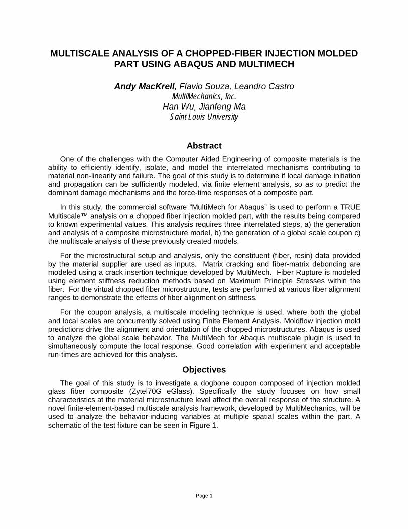
glass fiber composite (Zytel70G eGlass). Specifically the study focuses on how small characteristics at the material microstructure level affect the overall response of the structure. A novel finite-element-based multiscale analysis framework, developed by MultiMechanics, will be used to analyze the behavior-inducing variables at multiple spatial scales within the part. A schematic of the test fixture can be seen in Figure 1.
Page 2
Figure 1: A schematic of the dogbone coupon
The virtual analysis of this part are be performed in serial, starting with the analysis of a single chopped fiber representative volume element (RVE) and working up to a full part.
The paper addresses the following key challenges in the virtual analysis of composite parts, using the part in Figure 1 as an example:
1. Which variables of a composite part need to be accounted for in the model of interest? 2. Which composite damage mechanisms need to be considered and how can they be
represented using FEA? 3. What is the nonlinear response of my part, under multiple loading scenarios? 4. Which damage mechanisms are contributing to part failure, so that designs can be
selectively improved? 5. How can perform physics-based composite analysis be performed in mainstream CAE
tools? Because of the complexity inherent in composite parts, there are a number of different
approaches that have been developed to predict and analyzing their behaviors. In general all approaches for predicting composite behavior fall into one of two categories a) Analytical Approaches b) Modeling Approaches. A brief review of both will be covered in the following sections.
From a cost and transitive perspective, it is much more desirable to develop a model that can predict the properties of a heterogeneous material by only knowing about the behavior of the homogeneous phases.
Composite Analysis Theory and Background There exists a hierarchy when it comes to the level of detail that can be incorporated into a
virtual model (seen in Figure 2). Within this hierarchy there is an inherent balance between model fidelity, computational runtime, and overall design cost.
An open questions is then: what is the most efficient, accurate, and cost-effective way to predict composite part behavior? The part could be built and tested, eliminating the need for virtual predictions. A laminate of similar layup could be built and the properties extrapolated. Further, a ply or the composition of a ply could be analyzed a similar extrapolation could occur.
Page 3
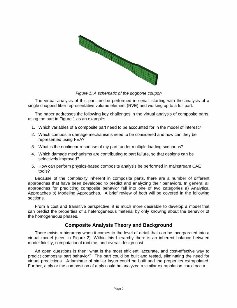
Figure 2: The hierarchy of composite composition. The width of the pyramid represents both the size of the design-space and the amount of constituent inputs required.
Further, the atomic force-fields that govern constituent behavior could be analyzed and used to predict all interactions relevant interactions [1]. The lower on the pyramid, the larger the design space. However there’s also an increase in setup, runtime, and model complexity. Deciding which level is ideal for a given analysis has to do with the wide variety of geometries and damage mechanisms found within composites, as seen in Table 1 below.
A Problem of Scales Different types of composites exhibit different behaviors at vastly different spatial scales
within a part. Further, because of fiber alignment considerations, at given material an behave like steel when loaded in one direction and rubber when loaded transversely.
In an effort to efficiently predict this complex behavior, a simulation methodology called “multiscale analysis” has emerged as a leading contender. Multiscale analysis is a broadly used term to describe any instance where a physical problem is solved by concurrently capturing the system’s behavior and important features at multiple scales, particularly multiple spatial and(or) temporal scales[4,5,6]. In principle, this approach can be used on as many continuum length scales as necessary as long as the assumption of separation of scales and the limits of continuum mechanics are valid [4]. The effective constitutive behavior of one scale is then governed by the behavior of the consecutive nested smaller scales, such that the only model input parameters are the material properties of individual constituents at the smallest length scale and respective fracture properties (and chemical properties) at each appropriate length scale.
In the realm of multiscale analysis of composites, there are two common approaches. One approach is to construct an analytical equation to predict the local (composite microstructure) properties. The other approach is to consider the phases of the composite as distinct materials and use a computational method to predict the resulting behavior of their interaction.
Page 4
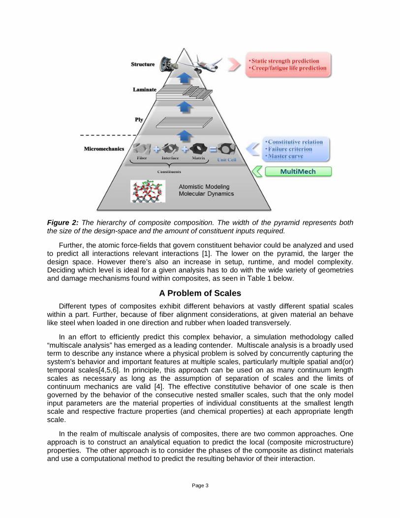
Composite Type Behavior-Inducing Variables and Mechanisms
Unidirectional
Fiber rupture, matrix cracking fiber-matrix debonding, fiber-bridging, kink-banding, delamination, resin viscoelasticity
Chopped Fiber
Fiber breaks, fiber curvature, matrix cracking, cohesive interfacial behavior, resin viscoelasticity [2]
Voided, Foam, Particulate
Foam plasticity, Crack growth, cell crushing, void distribution
Woven
Pattern geometry, weave uncrimping, fiber waviness, tow-friction, fiber breaks [3]
Table 1: Common damage mechanisms found within different types of composite materials. Most are the result of interactions at the microstructural level.
In the analytical approaches, the material behavior is governed by a constitutive equation [7,8]. Equations like rule of mixtures, Mori Tanaka, and Johnson-Cook plasticity model are common constitutive equations that take into account the composite makeup. They take into account orthotropicity and the geometric effects of inclusions, but are fundamentally based on a single governing equation that predicts the smeared behavior of the composite system. Usually some, or a substantial amount of physical testing and curve fitting is required to calibrate these equations, although not always. In this paper, this is referred to as the top-down (empirical) approach
The other approach, known as the bottom-up (micromechanical) approach attempts to deconstruct the phases of a system and analyze their interactions, in the same way the interactions of a pin and joint could be analyzed. Different computational methods have been developed to simulate these interactions (e.g. finite element analysis, peridynamics) [10,11,12]. As much as possible, these approaches aim to model individual mechanisms of local failure in order to eliminate any smeared characterizations. Further, system properties are obtained from first-principle [13] test methods, rather than using reverse engineering techniques.
There is obviously a spectrum between the extremes of the top-down and bottom up approaches.
Page 5
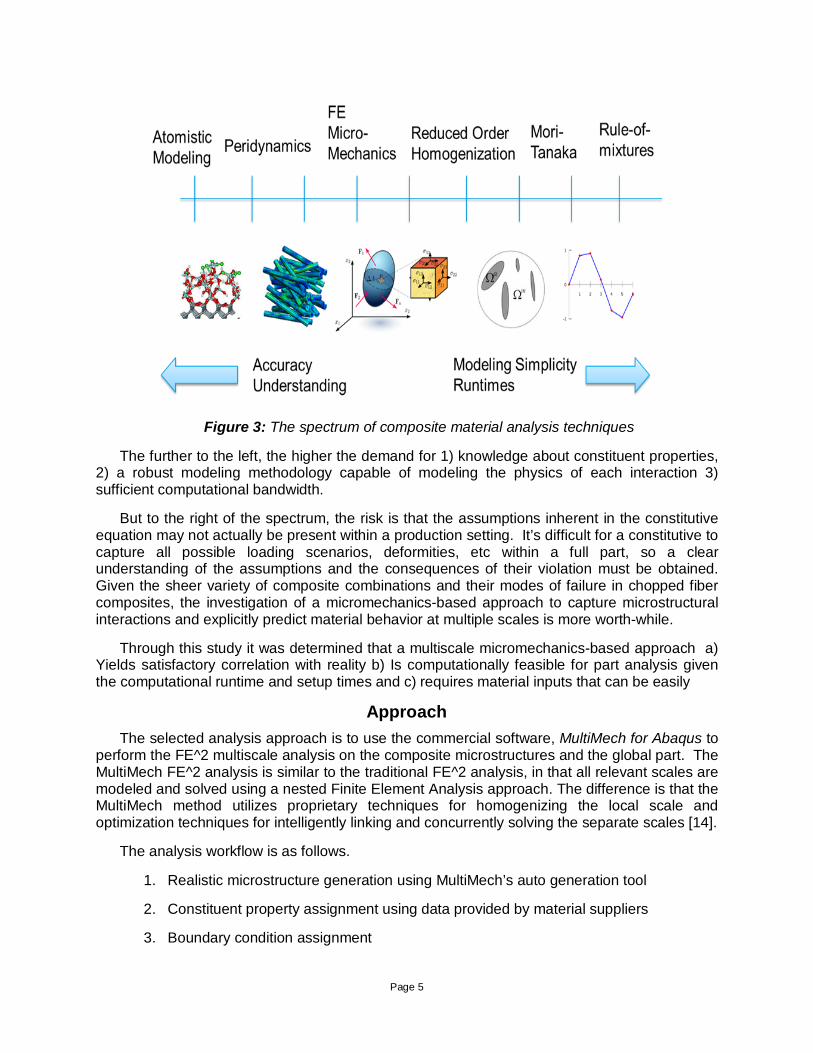
Figure 3: The spectrum of composite material analysis techniques
The further to the left, the higher the demand for 1) knowledge about constituent properties, 2) a robust modeling methodology capable of modeling the physics of each interaction 3) sufficient computational bandwidth.
But to the right of the spectrum, the risk is that the assumptions inherent in the constitutive equation may not actually be present within a production setting. It’s difficult for a constitutive to capture all possible loading scenarios, deformities, etc within a full part, so a clear understanding of the assumptions and the consequences of their violation must be obtained. Given the sheer variety of composite combinations and their modes of failure in chopped fiber composites, the investigation of a micromechanics-based approach to capture microstructural interactions and explicitly predict material behavior at multiple scales is more worth-while.
Through this study it was determined that a multiscale micromechanics-based approach a) Yields satisfactory correlation with reality b) Is computationally feasible for part analysis given the computational runtime and setup times and c) requires material inputs that can be easily
Approach The selected analysis approach is to use the commercial software, MultiMech for Abaqus to
perform the FE^2 multiscale analysis on the composite microstructures and the global part. The MultiMech FE^2 analysis is similar to the traditional FE^2 analysis, in that all relevant scales are modeled and solved using a nested Finite Element Analysis approach. The difference is that the MultiMech method utilizes proprietary techniques for homogenizing the local scale and optimization techniques for intelligently linking and concurrently solving the separate scales [14].
The analysis workflow is as follows.
1. Realistic microstructure generation using MultiMech’s auto generation tool
2. Constituent property assignment using data provided by material suppliers
3. Boundary condition assignment
Page 6
4. RVE Virtual Test execution
5. Design of global part
6. Embed validated microstructure (RVE) within the global part
7. Two-way-coupled multiscale analysis
The core of this approach is the generation and analysis of realistic (non-idealized) Finite Element representation of the composite microstructure. These FE representations are known as Representative Volume Elements (RVEs) and much attention is given to their proper construction and characterization.
Composite System 1 Glass Fiber
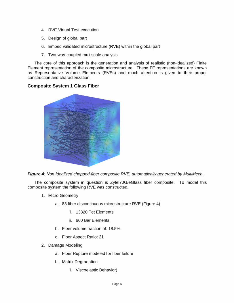
Figure 4: Non-idealized chopped-fiber composite RVE, automatically generated by MultiMech.
The composite system in question is Zytel70G/eGlass fiber composite. To model this composite system the following RVE was constructed.
1. Micro Geometry
a. 83 fiber discontinuous microstructure RVE (Figure 4)
i. 13320 Tet Elements
ii. 660 Bar Elements
b. Fiber volume fraction of: 18.5%
c. Fiber Aspect Ratio: 21
2. Damage Modeling
a. Fiber Rupture modeled for fiber failure
b. Matrix Degradation
i. Viscoelastic Behavior)
Page 7
ii. Matrix Ultimate Stress (Tensile, Shear)
c. Fiber-Matrix Debonding
i. Matrix Failure in high stress regions around fiber
The fiber was modeled as isotropic elastic. The matrix was modeled as viscoelastic, per a
literature review of the resin behavior, but an isotropic approximation of the viscoelastic behavior is seen in Table 2. The importance of capturing the gradual degradation of GFRP resins has been well documented [15]
Table 2: Linear Elastic inputs used to model the RVE. *Resin in the nonlinear RVE tests’ was modeled as viscoelastic with linear regime values approximately equivalent to the values in
Table 2.
E v
Isotropic Fiber [16] 72.5 0.23
Isotropic Resin* [17] 2.975 0.41
Viscoelasticity
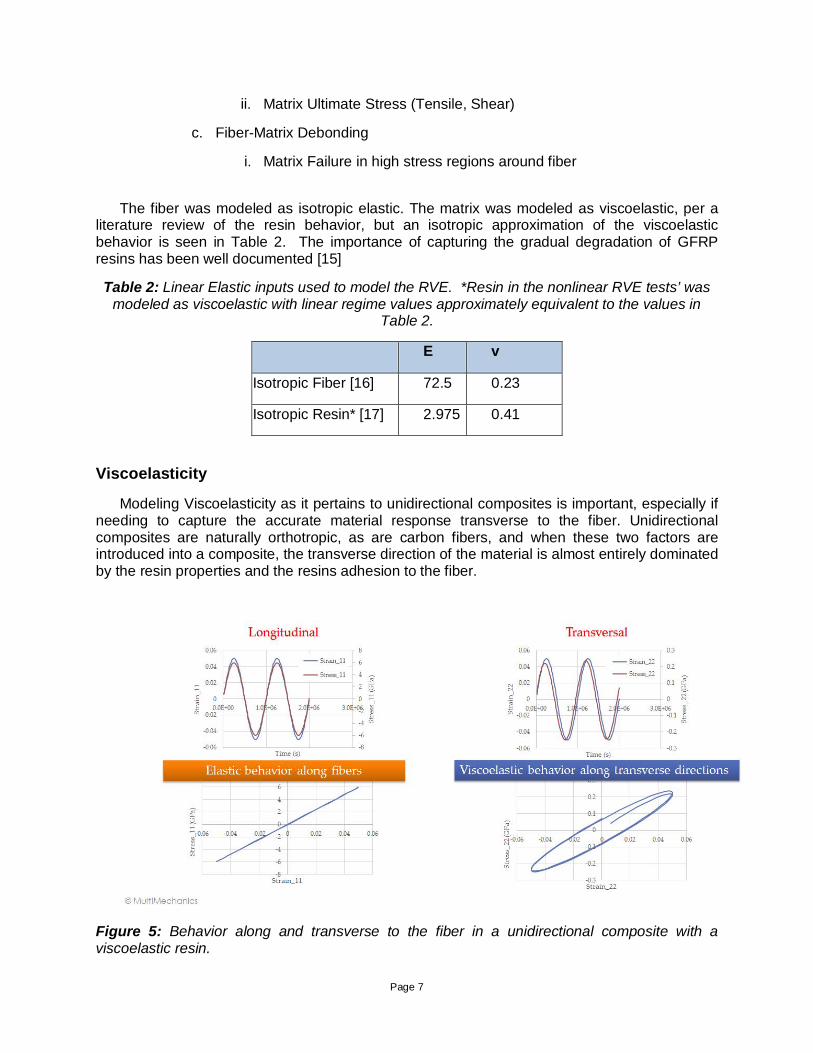
Modeling Viscoelasticity as it pertains to unidirectional composites is important, especially if needing to capture the accurate material response transverse to the fiber. Unidirectional composites are naturally orthotropic, as are carbon fibers, and when these two factors are introduced into a composite, the transverse direction of the material is almost entirely dominated by the resin properties and the resins adhesion to the fiber.
Figure 5: Behavior along and transverse to the fiber in a unidirectional composite with a viscoelastic resin.
Page 8
While rate dependency in static parts may not be a concern, stress relaxation and creep behavior may be. Notice in Figure 5 that transverse to the fiber, the stress and strain are slightly out of phase due to the dissipated energy. Further, the loading and unloading curves are quite different. The area under that curve is the dissipated energy.
To obtain viscoelastic constants, a Dynamic Mechanical Analysis (DMA) test can be run to obtain the frequency sweep data on the material. This yields a function that varies with temperature and time. Using the principles of Frequency-temperature-time - superposition, a Prony series of the frequency-sweep results can be created that captures the viscoelastic behavior in a concise form [21].
Aside from the viscoelastic response of the matrix, several other damage mechanisms are extracted from the constituent datasheets and used within the microstructure model. As seen in Table 3, damage modeling in MultiMech was performed by defining the key strength characteristics of the constituents and the strength of the interface between them. For the eGlass fiber the tensile, compressive, and shear strengths of the fiber were modeled using an element stiffness reduction technique.
Failure in the matrix is based on known tensile and shear matrix strengths (mode 1 and mode 2, respectively) and were also modeled using a stiffness reduction technique. This failure also doubles to capture the effects of debonding in the model. The reason being, that the stress gradients between the high stiffness fiber and low stiffness matrix will result in matrix failure at these interface locations, thus freeing the connection between fiber and matrix. The resulting displacement discontinuity and the inability of the matrix to redistribute stress to the fiber are the phenomenological outcomes of a debonding event.
Table 3: The damage parameters used in the chopped fiber RVE seen in Figure 4
Strengths (GPA) 1. eGlass Fiber [16]
4. Zytel70G Matrix [17]
Tensile 1900 90
Compressive 3000 10
Shear 1200 68
Weibull Modulus .3 2
Results Homogenization
The first step in the analysis was to validate that the homogenized linear properties of the discontinuous fiber composite were in-line with those measured experimentally using MultiMech’s homogenization. Seen in Table 4, this approach shows good correlation in the properties along the fiber and reasonably good correlation transverse and in shear.
Page 9
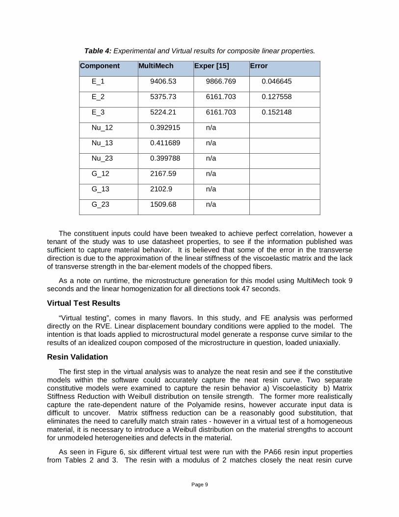
Table 4: Experimental and Virtual results for composite linear properties.
Component MultiMech Exper [15] Error
E_1 9406.53 9866.769 0.046645
E_2 5375.73 6161.703 0.127558
E_3 5224.21 6161.703 0.152148
Nu_12 0.392915 n/a
Nu_13 0.411689 n/a
Nu_23 0.399788 n/a
G_12 2167.59 n/a
G_13 2102.9 n/a
G_23 1509.68 n/a
The constituent inputs could have been tweaked to achieve perfect correlation, however a tenant of the study was to use datasheet properties, to see if the information published was sufficient to capture material behavior. It is believed that some of the error in the transverse direction is due to the approximation of the linear stiffness of the viscoelastic matrix and the lack of transverse strength in the bar-element models of the chopped fibers.
As a note on runtime, the microstructure generation for this model using MultiMech took 9 seconds and the linear homogenization for all directions took 47 seconds.
Virtual Test Results
“Virtual testing”, comes in many flavors. In this study, and FE analysis was performed directly on the RVE. Linear displacement boundary conditions were applied to the model. The intention is that loads applied to microstructural model generate a response curve similar to the results of an idealized coupon composed of the microstructure in question, loaded uniaxially.
Resin Validation
The first step in the virtual analysis was to analyze the neat resin and see if the constitutive models within the software could accurately capture the neat resin curve. Two separate constitutive models were examined to capture the resin behavior a) Viscoelasticity b) Matrix Stiffness Reduction with Weibull distribution on tensile strength. The former more realistically capture the rate-dependent nature of the Polyamide resins, however accurate input data is difficult to uncover. Matrix stiffness reduction can be a reasonably good substitution, that eliminates the need to carefully match strain rates - however in a virtual test of a homogeneous material, it is necessary to introduce a Weibull distribution on the material strengths to account for unmodeled heterogeneities and defects in the material.
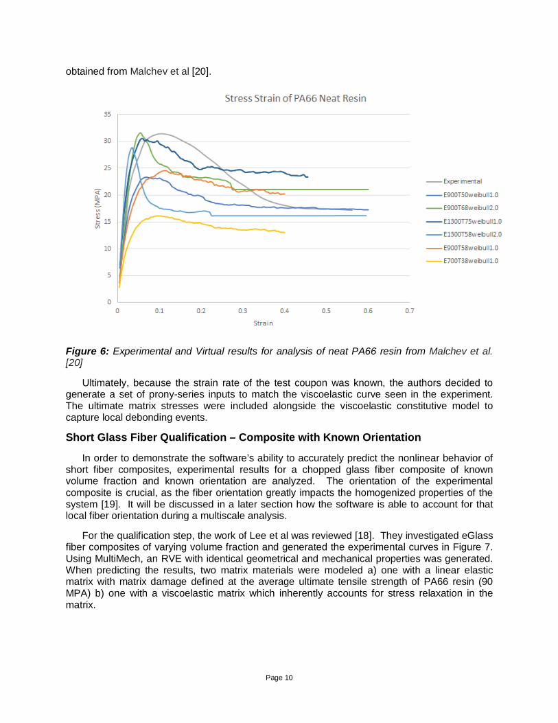
As seen in Figure 6, six different virtual test were run with the PA66 resin input properties from Tables 2 and 3. The resin with a modulus of 2 matches closely the neat resin curve
Page 10
obtained from Malchev et al [20].
Figure 6: Experimental and Virtual results for analysis of neat PA66 resin from Malchev et al. [20]
Ultimately, because the strain rate of the test coupon was known, the authors decided to generate a set of prony-series inputs to match the viscoelastic curve seen in the experiment. The ultimate matrix stresses were included alongside the viscoelastic constitutive model to capture local debonding events.
Short Glass Fiber Qualification – Composite with Known Orientation
In order to demonstrate the software’s ability to accurately predict the nonlinear behavior of short fiber composites, experimental results for a chopped glass fiber composite of known volume fraction and known orientation are analyzed. The orientation of the experimental composite is crucial, as the fiber orientation greatly impacts the homogenized properties of the system [19]. It will be discussed in a later section how the software is able to account for that local fiber orientation during a multiscale analysis.
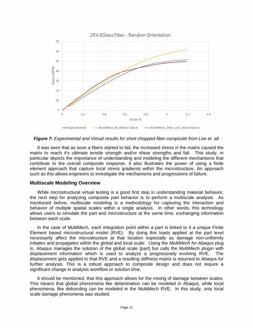
For the qualification step, the work of Lee et al was reviewed [18]. They investigated eGlass fiber composites of varying volume fraction and generated the experimental curves in Figure 7. Using MultiMech, an RVE with identical geometrical and mechanical properties was generated. When predicting the results, two matrix materials were modeled a) one with a linear elastic matrix with matrix damage defined at the average ultimate tensile strength of PA66 resin (90 MPA) b) one with a viscoelastic matrix which inherently accounts for stress relaxation in the matrix.
Page 11
Figure 7: Experimental and Virtual results for short chopped fiber composite from Lee et. all.
It was seen that as soon a fibers started to fail, the increased stress in the matrix caused the matrix to reach it’s ultimate tensile strength and/or shear strengths and fail. This study, in particular depicts the importance of understanding and modeling the different mechanisms that contribute to the overall composite response. It also illustrates the power of using a finite element approach that capture local stress gradients within the microstructure. An approach such as this allows engineers to investigate the mechanisms and progressions of failure.
Multiscale Modeling Overview
While microstructural virtual testing is a good first step in understanding material behavior, the next step for analyzing composite part behavior is to perform a multiscale analysis. As mentioned before, multiscale modeling is a methodology for capturing the interaction and behavior of multiple spatial scales within a single analysis. In other words, this technology allows users to simulate the part and microstructure at the same time, exchanging information between each scale.
In the case of MultiMech, each integration point within a part is linked to it a unique Finite Element based microstructural model (RVE). By doing this loads applied at the part level necessarily affect the microstructure at that location especially as damage non-uniformly initiates and propagates within the global and local scale. Using the MultiMech for Abaqus plug in, Abaqus manages the solution of the global scale (part) but calls the MultiMech plugin with displacement information which is used to analyze a progressively evolving RVE. The displacement gets applied to that RVE and a resulting stiffness matrix is returned to Abaqus for further analysis. This is a robust approach to composite design and does not require a significant change in analysis workflow or solution time.
It should be mentioned, that this approach allows for the mixing of damage between scales. This means that global phenomena like delamination can be modeled in Abaqus, while local phenomena, like debonding can be modeled in the MultiMech RVE. In this study, only local scale damage phenomena was studied.
Page 12
Multiscale Modeling - 10 Degree Test
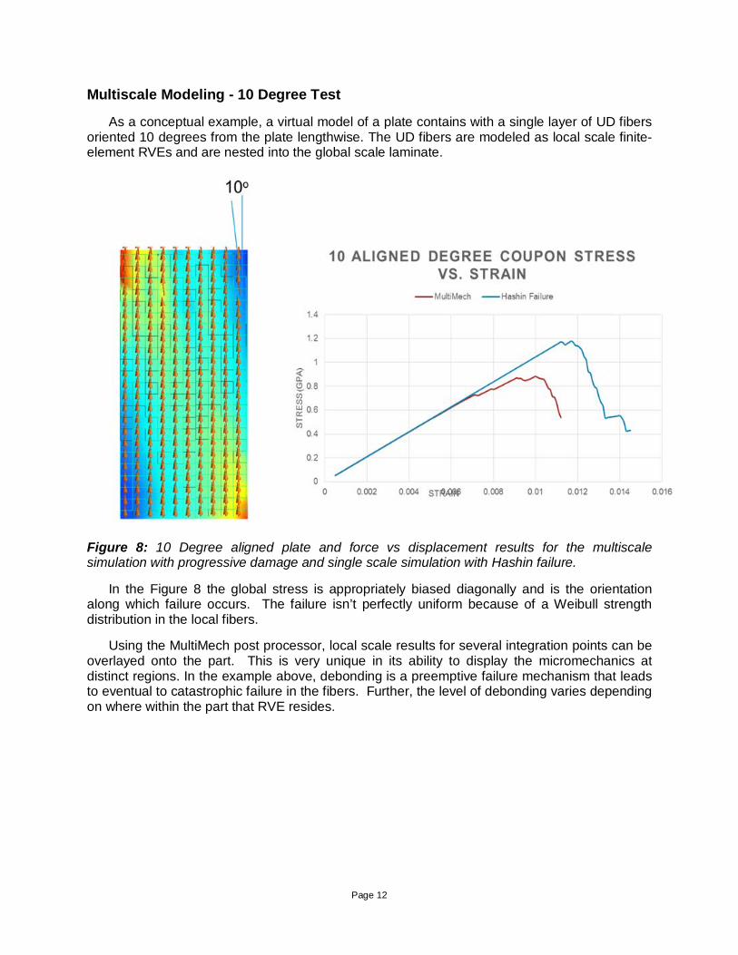
As a conceptual example, a virtual model of a plate contains with a single layer of UD fibers oriented 10 degrees from the plate lengthwise. The UD fibers are modeled as local scale finite-element RVEs and are nested into the global scale laminate.
Figure 8: 10 Degree aligned plate and force vs displacement results for the multiscale simulation with progressive damage and single scale simulation with Hashin failure.
In the Figure 8 the global stress is appropriately biased diagonally and is the orientation along which failure occurs. The failure isn’t perfectly uniform because of a Weibull strength distribution in the local fibers.
Using the MultiMech post processor, local scale results for several integration points can be overlayed onto the part. This is very unique in its ability to display the micromechanics at distinct regions. In the example above, debonding is a preemptive failure mechanism that leads to eventual to catastrophic failure in the fibers. Further, the level of debonding varies depending on where within the part that RVE resides.
Page 13
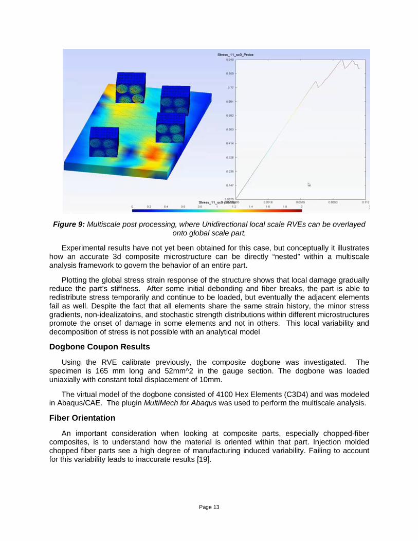
Figure 9: Multiscale post processing, where Unidirectional local scale RVEs can be overlayed onto global scale part.
Experimental results have not yet been obtained for this case, but conceptually it illustrates how an accurate 3d composite microstructure can be directly “nested” within a multiscale analysis framework to govern the behavior of an entire part.
Plotting the global stress strain response of the structure shows that local damage gradually reduce the part’s stiffness. After some initial debonding and fiber breaks, the part is able to redistribute stress temporarily and continue to be loaded, but eventually the adjacent elements fail as well. Despite the fact that all elements share the same strain history, the minor stress gradients, non-idealizatoins, and stochastic strength distributions within different microstructures promote the onset of damage in some elements and not in others. This local variability and decomposition of stress is not possible with an analytical model
Dogbone Coupon Results
Using the RVE calibrate previously, the composite dogbone was investigated. The specimen is 165 mm long and 52mm^2 in the gauge section. The dogbone was loaded uniaxially with constant total displacement of 10mm.
The virtual model of the dogbone consisted of 4100 Hex Elements (C3D4) and was modeled in Abaqus/CAE. The plugin MultiMech for Abaqus was used to perform the multiscale analysis.
Fiber Orientation
An important consideration when looking at composite parts, especially chopped-fiber composites, is to understand how the material is oriented within that part. Injection molded chopped fiber parts see a high degree of manufacturing induced variability. Failing to account for this variability leads to inaccurate results [19].
Page 14
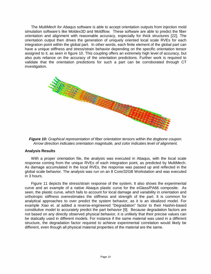
The MultiMech for Abaqus software is able to accept orientation outputs from injection mold simulation software’s like Moldex3D and Moldflow. These software are able to predict the fiber orientation and alignment with reasonable accuracy, especially for thick structures [22]. The orientation output then drives the generation of uniquely oriented local scale RVEs for each integration point within the global part. In other words, each finite element of the global part can have a unique stiffness and stress/strain behavior depending on the specific orientation tensor assigned to it, as seen in figure 10. This coupling offers an extremely high level of accuracy, but also puts reliance on the accuracy of the orientation predictions. Further work is required to validate that the orientation predictions for such a part can be corroborated through CT investigation.
Figure 10: Graphical representation of fiber orientation tensors within the dogbone coupon. Arrow direction indicates orientation magnitude, and color indicates level of alignment.
Analysis Results
With a proper orientation file, the analysis was executed in Abaqus, with the local scale response coming from the unique RVEs of each integration point, as predicted by MultiMech. As damage accumulated in the local RVEs, the response was passed up and reflected in the global scale behavior. The analysis was run on an 8 Core/32GB Workstation and was executed in 3 hours.
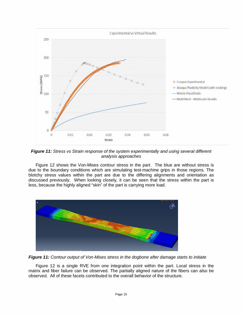
Figure 11 depicts the stress/strain response of the system. It also shows the experimental curve and an example of a native Abaqus plastic curve for the eGlass/PA66 composite. As seen, the plastic curve, which fails to account for local damage and variability in orientation and orthotropic stiffness overestimates the stiffness and strength of the part. It is common for analytical approaches to over predict the system behavior, as it is an idealized model. For example Xiao et. al added a reverse-engineered “Degradation” factor to their Hashin-based constitutive model to accurately predict the part behavior [9]. Because degradation factors are not based on any directly observed physical behavior, it is unlikely that their precise values can be statically used in different models. For instance if the same material was used in a different structure, the degradation factor required to achieve experimental correlation would likely be different, even though all physical material properties of the material are the same.
Page 15
Figure 11: Stress vs Strain response of the system experimentally and using several different analysis approaches
Figure 12 shows the Von-Mises contour stress in the part. The blue are without stress is due to the boundary conditions which are simulating test-machine grips in those regions. The blotchy stress values within the part are due to the differing alignments and orientation as discussed previously. When looking closely, it can be seen that the stress within the part is less, because the highly aligned “skin” of the part is carrying more load.
Figure 11: Contour output of Von-Mises stress in the dogbone after damage starts to initiate
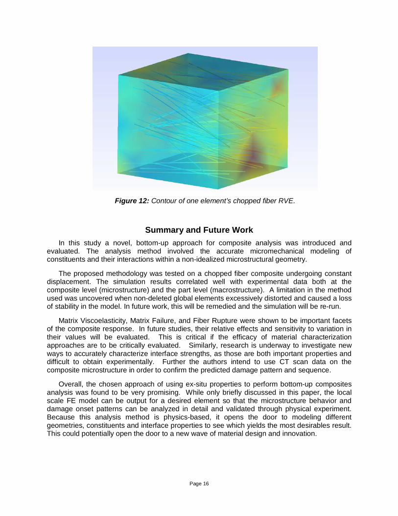
Figure 12 is a single RVE from one integration point within the part. Local stress in the matrix and fiber failure can be observed. The partially aligned nature of the fibers can also be observed. All of these facets contributed to the overall behavior of the structure.
Page 16
Figure 12: Contour of one element’s chopped fiber RVE.
Summary and Future Work In this study a novel, bottom-up approach for composite analysis was introduced and
evaluated. The analysis method involved the accurate micromechanical modeling of constituents and their interactions within a non-idealized microstructural geometry.
The proposed methodology was tested on a chopped fiber composite undergoing constant displacement. The simulation results correlated well with experimental data both at the composite level (microstructure) and the part level (macrostructure). A limitation in the method used was uncovered when non-deleted global elements excessively distorted and caused a loss of stability in the model. In future work, this will be remedied and the simulation will be re-run.
Matrix Viscoelasticity, Matrix Failure, and Fiber Rupture were shown to be important facets of the composite response. In future studies, their relative effects and sensitivity to variation in their values will be evaluated. This is critical if the efficacy of material characterization approaches are to be critically evaluated. Similarly, research is underway to investigate new ways to accurately characterize interface strengths, as those are both important properties and difficult to obtain experimentally. Further the authors intend to use CT scan data on the composite microstructure in order to confirm the predicted damage pattern and sequence.
Overall, the chosen approach of using ex-situ properties to perform bottom-up composites analysis was found to be very promising. While only briefly discussed in this paper, the local scale FE model can be output for a desired element so that the microstructure behavior and damage onset patterns can be analyzed in detail and validated through physical experiment. Because this analysis method is physics-based, it opens the door to modeling different geometries, constituents and interface properties to see which yields the most desirables result. This could potentially open the door to a new wave of material design and innovation.
Page 17
References 1. Frankland, S. J. V., et al. "The stress–strain behavior of polymer–nanotube composites
from molecular dynamics simulation." Composites Science and Technology 63.11 (2003): 1655-1661.
2. Agarwal, Bhagwan D., Lawrence J. Broutman, and K. Chandrashekhara.Analysis and performance of fiber composites. John Wiley & Sons, 2006.
3. Brandt, J., K. Drechsler, and F-J. Arendts. "Mechanical performance of composites based on various three-dimensional woven-fibre preforms."Composites Science and Technology 56.3 (1996): 381-386.
4. Souza, F. V., D. H. Allen, and Y-R. Kim. "Multiscale model for predicting damage evolution in composites due to impact loading." Composites science and technology 68.13 (2008): 2624-2634
5. Kanouté, P., et al. "Multiscale methods for composites: a review." Archives of Computational Methods in Engineering 16.1 (2009): 31-75.
6. Fish, Jacob, and Kamlun Shek. "Multiscale analysis of composite materials and structures." Composites Science and Technology 60.12 (2000): 2547-2556.
7. Hinton, Mike J., A. Sam Kaddour, and Peter D. Soden. Failure criteria in fibre reinforced polymer composites: the world-wide failure exercise. Elsevier, 2004.
8. Adam, Laurent, Alexandre Depouhon, and Roger Assaker. "Multi-Scale Modeling of Crash & Failure of Reinforced Plastics Parts with DIGIMAT to LS-DYNA interface." 7th European LS-DYNA Conference. 2009.
9. Xiao, Yi, and Takashi Ishikawa. "Bearing strength and failure behavior of bolted composite joints (part I: Experimental investigation)." Composites Science and Technology 65.7 (2005): 1022-1031.
10. Kanouté, P., et al. "Multiscale methods for composites: a review." Archives of Computational Methods in Engineering 16.1 (2009): 31-75.
11. Fish, Jacob, and Kamlun Shek. "Multiscale analysis of composite materials and structures." Composites Science and Technology 60.12 (2000): 2547-2556.
12. Hu, Wenke, Youn Doh Ha, and Florin Bobaru. "Peridynamic model for dynamic fracture in unidirectional fiber-reinforced composites." Computer Methods in Applied Mechanics and Engineering 217 (2012): 247-261.
13. Gonze, Xavier, et al. "First-principles computation of material properties: the ABINIT software project." Computational Materials Science 25.3 (2002): 478-492.
14. Proceedings of the American Society for Composites, Seventeenth Technical C. T. Sun 15. Meraghni, Fodil, and M. L. Benzeggagh. "Micromechanical modelling of matrix
degradation in randomly oriented discontinuous-fibre composites."Composites science and technology 55.2 (1995): 171-186.
16. Fu, S-Y., et al. "Tensile properties of short-glass-fiber-and short-carbon-fiber-reinforced polypropylene composites." Composites Part A: Applied Science and Manufacturing 31.10 (2000): 1117-1125.
17. Zytel Fiber Properties, http://www.cpinfo.net/scissc/Zytel/70G33L.pdf 18. Lee, H. K., and S. Simunovic. "Modeling of progressive damage in aligned and randomly
oriented discontinuous fiber polymer matrix composites."Composites Part B: Engineering 31.2 (2000): 77-86.
19. Fu, Shao-Yun, and Bernd Lauke. "Effects of fiber length and fiber orientation distributions on the tensile strength of short-fiber-reinforced polymers."Composites Science and Technology 56.10 (1996): 1179-1190.
20. Malchev, Plamen G., et al. "Mechanical and fracture properties of ternary PE/PA6/GF composites." Composites Science and Technology 70.5 (2010): 734-742.

Page 18
21. Tzikang, Chen. "Determining a Prony series for a viscoelastic material from time varying strain data." (2000).
22. Advani, Suresh G., and Charles L. Tucker III. "The use of tensors to describe and predict fiber orientation in short fiber composites." Journal of Rheology (1978-present) 31.8 (1987): 751-784.


![Fabrication of carbon fiber SMC composites with vinyl ...carbonlett.org/Upload/files/CARBONLETT/[101-104]-11.pdf · of fiber reinforced plastic composites, ... (1 inch chopped carbon](https://img.pdfslide.us/doc/110x75/5ad58c6d7f8b9a48398dbb07/fabrication-of-carbon-fiber-smc-composites-with-vinyl-101-104-11pdfof-fiber.jpg)


![Flexural Behaviour of Basalt Fiber Reinforced Concrete ... · Basalt rock can also make basalt rock, chopped basalt fiber, basalt fabrics and continuous filament wire [9]. Basalt](https://img.pdfslide.us/doc/110x75/5e8d373fa059ea2b69053027/flexural-behaviour-of-basalt-fiber-reinforced-concrete-basalt-rock-can-also.jpg)