Embed Size (px)
Citation preview
COMPRESSION MOLDING OF LONG CHOPPED FIBER
THERMOPLASTIC COMPOSITES
D. DeWayne Howell, Scott Fukumoto
CCS Composites, a division of TenCate Advanced Composites
2450 Cordelia Road
Fairfield, CA 94534 USA
ABSTRACT
When it comes to fabricating advanced composite structures, there is an array of fabrication
processes available. However, when part complexity increases, performance is demanding and
higher volume production rates are required the field begins to narrow. One such method that
meets these criteria is compression molding with long chopped fiber thermoplastics.
Compression molding is the process by which a charge of fiber reinforced prepreg bulk molding
compound (BMC) is molded under heat and high pressures to form complex shaped parts. The
BMCs under discussion are created by chopping existing unidirectional fiber reinforced
thermoplastic tape into long lengths [6.4mm to 50.8mm (0.25 inch to 2.0 inch)]. These loose
chips or strands are then weighed out to the exact amount required to fill the volume of a given
tool, placed in a matched metal mold and heated and compressed to pressures that force the
fibers to flow into the mold cavity, filling in every complex feature before cooling.
Thermoplastic BMC compression molding requires a degree of mold temperature control not
normally required by thermoset compression molding. TenCate/CCS uses a tooling concept
called XPress to tightly control the mold temperature in zones over the surface of the part. Flat
plates and a carbon fiber/thermoplastic bracket with complex features has been molded using this
process. Structural test coupons have been molded and tested for stiffness and strength
characterization. State-of-the-art design and analysis routines are now available to aid in the
design of parts using these BMC materials.
1. INTRODUCTION
Compression molding of long, discontinuous fiber, thermoplastic composites had been around
since the 1990's (Ref. 1) where fiberglass and polypropylene found some application in the
automotive industry. For years prior to this, thermoset based sheet molding compounds (SMC)
had been and still are used. The aerospace industry has been using SMCs for years to fabricate
covers and other secondary structures. BMC differs from SMC in that the BMC raw material
consists of chopped flakes, chips or lengths of prereged fibers rather than a continuous sheet of
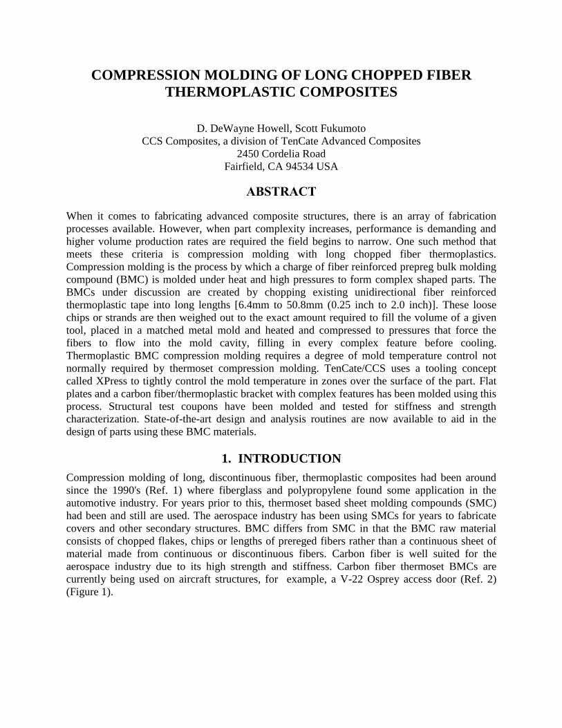
material made from continuous or discontinuous fibers. Carbon fiber is well suited for the
aerospace industry due to its high strength and stiffness. Carbon fiber thermoset BMCs are
currently being used on aircraft structures, for example, a V-22 Osprey access door (Ref. 2)
(Figure 1).
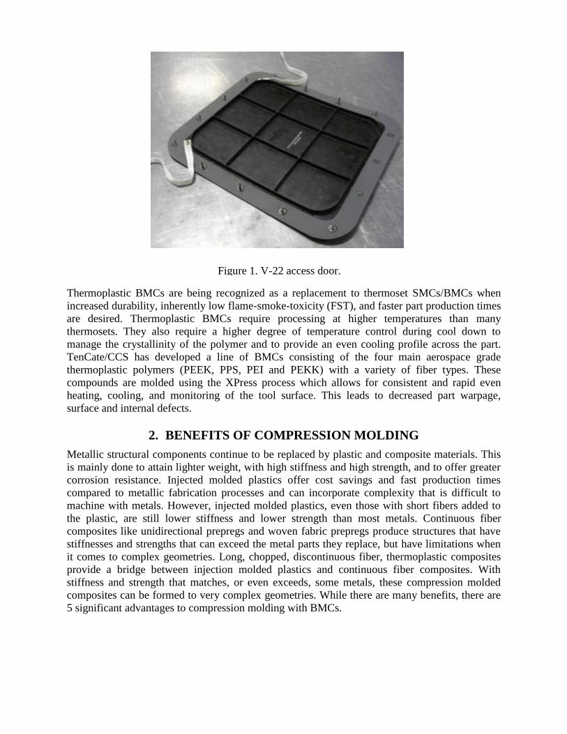
Figure 1. V-22 access door.
Thermoplastic BMCs are being recognized as a replacement to thermoset SMCs/BMCs when
increased durability, inherently low flame-smoke-toxicity (FST), and faster part production times
are desired. Thermoplastic BMCs require processing at higher temperatures than many
thermosets. They also require a higher degree of temperature control during cool down to
manage the crystallinity of the polymer and to provide an even cooling profile across the part.
TenCate/CCS has developed a line of BMCs consisting of the four main aerospace grade
thermoplastic polymers (PEEK, PPS, PEI and PEKK) with a variety of fiber types. These
compounds are molded using the XPress process which allows for consistent and rapid even
heating, cooling, and monitoring of the tool surface. This leads to decreased part warpage,
surface and internal defects.
2. BENEFITS OF COMPRESSION MOLDING
Metallic structural components continue to be replaced by plastic and composite materials. This
is mainly done to attain lighter weight, with high stiffness and high strength, and to offer greater
corrosion resistance. Injected molded plastics offer cost savings and fast production times
compared to metallic fabrication processes and can incorporate complexity that is difficult to
machine with metals. However, injected molded plastics, even those with short fibers added to
the plastic, are still lower stiffness and lower strength than most metals. Continuous fiber
composites like unidirectional prepregs and woven fabric prepregs produce structures that have
stiffnesses and strengths that can exceed the metal parts they replace, but have limitations when
it comes to complex geometries. Long, chopped, discontinuous fiber, thermoplastic composites
provide a bridge between injection molded plastics and continuous fiber composites. With
stiffness and strength that matches, or even exceeds, some metals, these compression molded
composites can be formed to very complex geometries. While there are many benefits, there are
5 significant advantages to compression molding with BMCs.
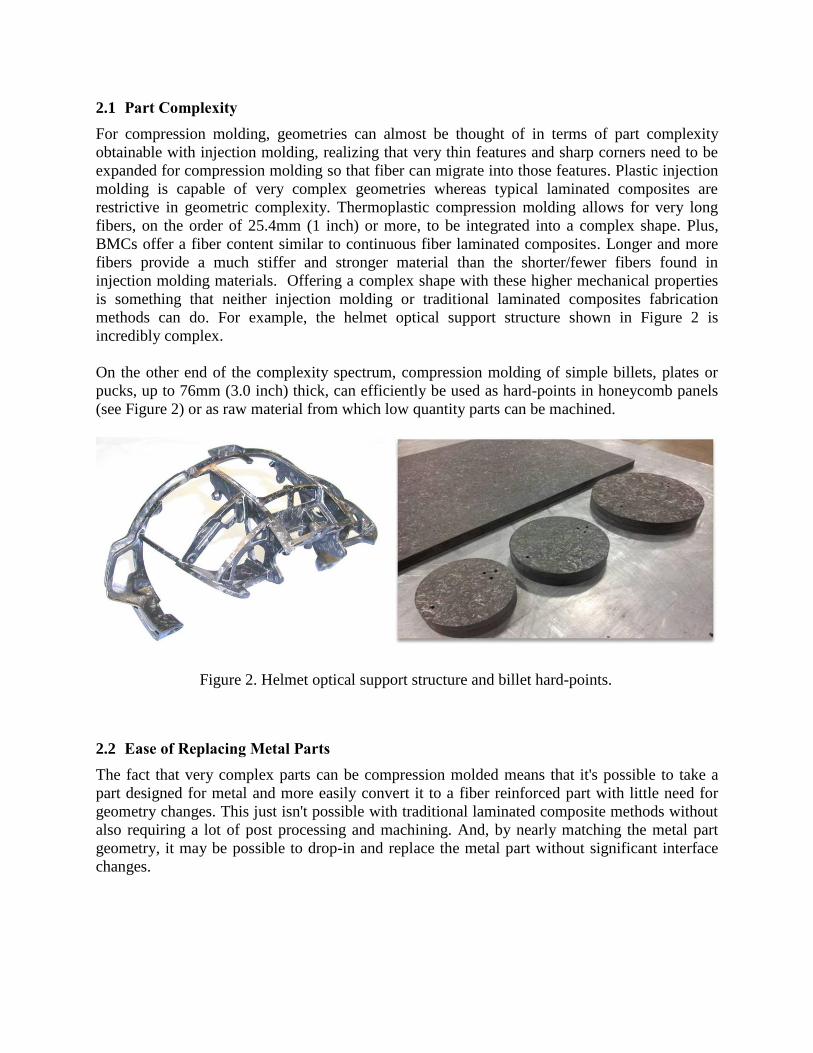
Figure 2. Helmet optical support structure and billet hard-points.
2.1 Part Complexity
For compression molding, geometries can almost be thought of in terms of part complexity
obtainable with injection molding, realizing that very thin features and sharp corners need to be
expanded for compression molding so that fiber can migrate into those features. Plastic injection
molding is capable of very complex geometries whereas typical laminated composites are
restrictive in geometric complexity. Thermoplastic compression molding allows for very long
fibers, on the order of 25.4mm (1 inch) or more, to be integrated into a complex shape. Plus,
BMCs offer a fiber content similar to continuous fiber laminated composites. Longer and more
fibers provide a much stiffer and stronger material than the shorter/fewer fibers found in
injection molding materials. Offering a complex shape with these higher mechanical properties
is something that neither injection molding or traditional laminated composites fabrication
methods can do. For example, the helmet optical support structure shown in Figure 2 is
incredibly complex.
On the other end of the complexity spectrum, compression molding of simple billets, plates or
pucks, up to 76mm (3.0 inch) thick, can efficiently be used as hard-points in honeycomb panels
(see Figure 2) or as raw material from which low quantity parts can be machined.
2.2 Ease of Replacing Metal Parts
The fact that very complex parts can be compression molded means that it's possible to take a
part designed for metal and more easily convert it to a fiber reinforced part with little need for
geometry changes. This just isn't possible with traditional laminated composite methods without
also requiring a lot of post processing and machining. And, by nearly matching the metal part
geometry, it may be possible to drop-in and replace the metal part without significant interface
changes.
Figure 3. Reinforcement ribs with inserts.
2.3 Inserts & Reinforcement Ribs
Adding inserts and reinforcement ribs is another advantage of compression molding (Figure 3).
Metallic or other material inserts can be placed into the mold at the time of forming. These
attachment hard points eliminate common secondary processes compared to other composite
manufacturing methods. Also, by incorporating ribs into a part, which is easily done by simply
adding such a feature to the tool, the bending stiffness and strength can be increased
dramatically, with little if any change in part cost. It isn't all that easy to incorporate ribs into
traditional laminated composite parts.
2.4 Dimensional Control and Stability
Dimensional control and stability are enhanced by the matched metal tooling used in
compression molding. Each part produced from the same tool is basically a dimensional
duplicate of the previous part. Some other composite fabrication processes rely on a soft material
to form one side; causing dimensional variation and then additional machining. While
compression molded parts can be machined, it is usually reserved for extremely high tolerance
areas or the few part section areas that will not be molded directly because of additional mold
complexity.
2.5 High Volume Production and Lower Costs
The finished part cost can be lower. It is not uncommon for a complete complex shaped part to
be produced in only 5-15 minutes. In addition, the ability to incorporate otherwise secondary
features and inserts, reduce labor content, produce low material scrap, achieve high part yields
and reduce part inspection time can all contribute to cost savings. Replacement of several
assembled, simple shaped parts with one complex compression molded part allows for savings in
assembly time and the inventory control of multiple parts.
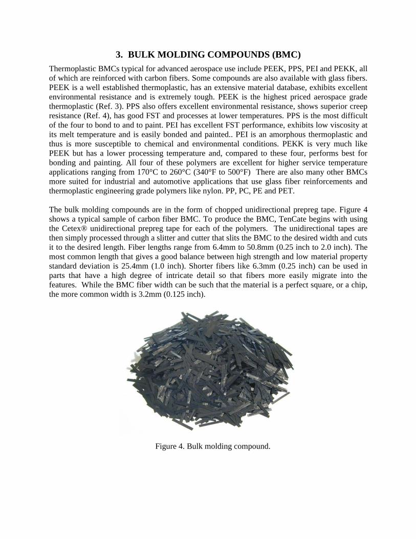
Figure 4. Bulk molding compound.
3. BULK MOLDING COMPOUNDS (BMC)
Thermoplastic BMCs typical for advanced aerospace use include PEEK, PPS, PEI and PEKK, all
of which are reinforced with carbon fibers. Some compounds are also available with glass fibers.
PEEK is a well established thermoplastic, has an extensive material database, exhibits excellent
environmental resistance and is extremely tough. PEEK is the highest priced aerospace grade
thermoplastic (Ref. 3). PPS also offers excellent environmental resistance, shows superior creep
resistance (Ref. 4), has good FST and processes at lower temperatures. PPS is the most difficult
of the four to bond to and to paint. PEI has excellent FST performance, exhibits low viscosity at
its melt temperature and is easily bonded and painted.. PEI is an amorphous thermoplastic and
thus is more susceptible to chemical and environmental conditions. PEKK is very much like
PEEK but has a lower processing temperature and, compared to these four, performs best for
bonding and painting. All four of these polymers are excellent for higher service temperature
applications ranging from 170°C to 260°C (340°F to 500°F) There are also many other BMCs
more suited for industrial and automotive applications that use glass fiber reinforcements and
thermoplastic engineering grade polymers like nylon. PP, PC, PE and PET.
The bulk molding compounds are in the form of chopped unidirectional prepreg tape. Figure 4
shows a typical sample of carbon fiber BMC. To produce the BMC, TenCate begins with using
the Cetex® unidirectional prepreg tape for each of the polymers. The unidirectional tapes are
then simply processed through a slitter and cutter that slits the BMC to the desired width and cuts
it to the desired length. Fiber lengths range from 6.4mm to 50.8mm (0.25 inch to 2.0 inch). The
most common length that gives a good balance between high strength and low material property
standard deviation is 25.4mm (1.0 inch). Shorter fibers like 6.3mm (0.25 inch) can be used in
parts that have a high degree of intricate detail so that fibers more easily migrate into the
features. While the BMC fiber width can be such that the material is a perfect square, or a chip,
the more common width is 3.2mm (0.125 inch).
3.1 Material Properties
Table 1 (Ref. 5,6) shows the material properties of two thermoplastic BMCs compared to
aluminum and titanium. In parts where the BMC can be more or less placed into all of the
features in the mold, the fiber orientations for the BMC take on a near quasi-isotropic random
layup. The table represents properties for this random layup. In cases where the BMC flows into
features, the fibers become more aligned, especially near the edges of the mold, and properties
begin to approach unidirectional values. Material properties for PEI and PEKK BMCs are
currently under development at TenCate/CCS.
Table 1. Standard modulus carbon fiber BMC, RTD properties, typical
Property
6061-T6
Aluminum
3AL-2.5V
Titanium
CF/PEEK
Cetex®
MC1200
CF/PPS
Cetex®
MC1100
Resin Content (Wr) na na 34% 34%
Tensile Strength, Mpa (ksi) 303 (44) 689 (100) 288.9 (41.9) 207 (30)
Tensile Modulus, GPa (Msi) 69 (10) 107 (15.5) 43.4 (6.3) 41.4 (6.0)
Flexural Strength, Mpa (ksi) 303 (44) 689 (100) 657.8 (95.4) 496 (72)
Flexural Modulus, GPa (Msi) 69 (10) 107 (15.5) 40.0 (5.8) 33.8 (4.9)
Compression Strength, Mpa (ksi) 303 (44) 689 (100) 312.2 (45.3) -
Compression Modulus, GPa (Msi) 70 (10.2) 109 (15.8) 48.3 (7.0) -
Open Hole Comp. Str., Mpa (ksi) - - 282.0 (40.9) -
3.2 Material Testing
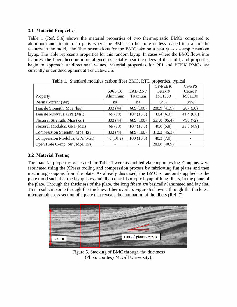
The material properties generated for Table 1 were assembled via coupon testing. Coupons were
fabricated using the XPress tooling and compression process by fabricating flat plates and then
machining coupons from the plate. As already discussed, the BMC is randomly applied to the
plate mold such that the layup is essentially a quasi-isotropic layup of long fibers, in the plane of
the plate. Through the thickness of the plate, the long fibers are basically laminated and lay flat.
This results in some through-the-thickness fiber overlap. Figure 5 shows a through-the-thickness
micrograph cross section of a plate that reveals the lamination of the fibers (Ref. 7).
Figure 5. Stacking of BMC through-the-thickness
(Photo courtesy McGill University).
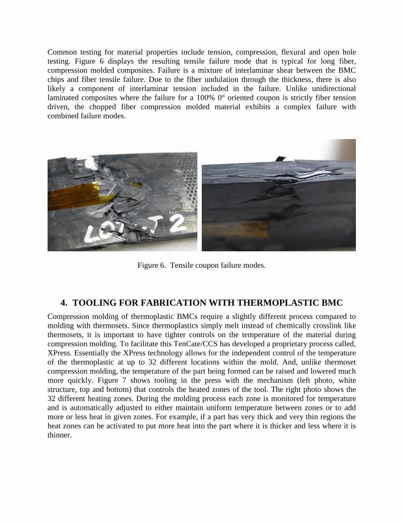
Common testing for material properties include tension, compression, flexural and open hole
testing. Figure 6 displays the resulting tensile failure mode that is typical for long fiber,
compression molded composites. Failure is a mixture of interlaminar shear between the BMC
chips and fiber tensile failure. Due to the fiber undulation through the thickness, there is also
likely a component of interlaminar tension included in the failure. Unlike unidirectional
laminated composites where the failure for a 100% 0° oriented coupon is strictly fiber tension
driven, the chopped fiber compression molded material exhibits a complex failure with
combined failure modes.
Figure 6. Tensile coupon failure modes.
4. TOOLING FOR FABRICATION WITH THERMOPLASTIC BMC
Compression molding of thermoplastic BMCs require a slightly different process compared to
molding with thermosets. Since thermoplastics simply melt instead of chemically crosslink like
thermosets, it is important to have tighter controls on the temperature of the material during
compression molding. To facilitate this TenCate/CCS has developed a proprietary process called,
XPress. Essentially the XPress technology allows for the independent control of the temperature
of the thermoplastic at up to 32 different locations within the mold. And, unlike thermoset
compression molding, the temperature of the part being formed can be raised and lowered much
more quickly. Figure 7 shows tooling in the press with the mechanism (left photo, white
structure, top and bottom) that controls the heated zones of the tool. The right photo shows the
32 different heating zones. During the molding process each zone is monitored for temperature
and is automatically adjusted to either maintain uniform temperature between zones or to add
more or less heat in given zones. For example, if a part has very thick and very thin regions the
heat zones can be activated to put more heat into the part where it is thicker and less where it is
thinner.
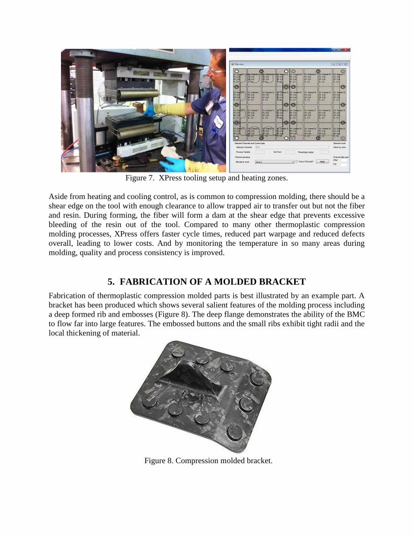
Figure 8. Compression molded bracket.
Figure 7. XPress tooling setup and heating zones.
Aside from heating and cooling control, as is common to compression molding, there should be a
shear edge on the tool with enough clearance to allow trapped air to transfer out but not the fiber
and resin. During forming, the fiber will form a dam at the shear edge that prevents excessive
bleeding of the resin out of the tool. Compared to many other thermoplastic compression
molding processes, XPress offers faster cycle times, reduced part warpage and reduced defects
overall, leading to lower costs. And by monitoring the temperature in so many areas during
molding, quality and process consistency is improved.
5. FABRICATION OF A MOLDED BRACKET
Fabrication of thermoplastic compression molded parts is best illustrated by an example part. A
bracket has been produced which shows several salient features of the molding process including
a deep formed rib and embosses (Figure 8). The deep flange demonstrates the ability of the BMC
to flow far into large features. The embossed buttons and the small ribs exhibit tight radii and the
local thickening of material.
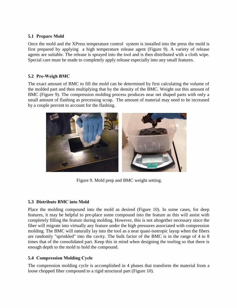
Figure 9. Mold prep and BMC weight setting.
5.1 Prepare Mold
Once the mold and the XPress temperature control system is installed into the press the mold is
first prepared by applying a high temperature release agent (Figure 9). A variety of release
agents are suitable. The release is sprayed into the tool and is then distributed with a cloth wipe.
Special care must be made to completely apply release especially into any small features.
5.2 Pre-Weigh BMC
The exact amount of BMC to fill the mold can be determined by first calculating the volume of
the molded part and then multiplying that by the density of the BMC. Weight out this amount of
BMC (Figure 9). The compression molding process produces near net shaped parts with only a
small amount of flashing as processing scrap. The amount of material may need to be increased
by a couple percent to account for the flashing.
5.3 Distribute BMC into Mold
Place the molding compound into the mold as desired (Figure 10). In some cases, for deep
features, it may be helpful to pre-place some compound into the feature as this will assist with
completely filling the feature during molding. However, this is not altogether necessary since the
fiber will migrate into virtually any feature under the high pressures associated with compression
molding. The BMC will naturally lay into the tool as a near quasi-isotropic layup when the fibers
are randomly "sprinkled" into the cavity. The bulk factor of the BMC is in the range of 4 to 8
times that of the consolidated part. Keep this in mind when designing the tooling so that there is
enough depth to the mold to hold the compound.
5.4 Compression Molding Cycle
The compression molding cycle is accomplished in 4 phases that transform the material from a
loose chopped fiber compound to a rigid structural part (Figure 10).
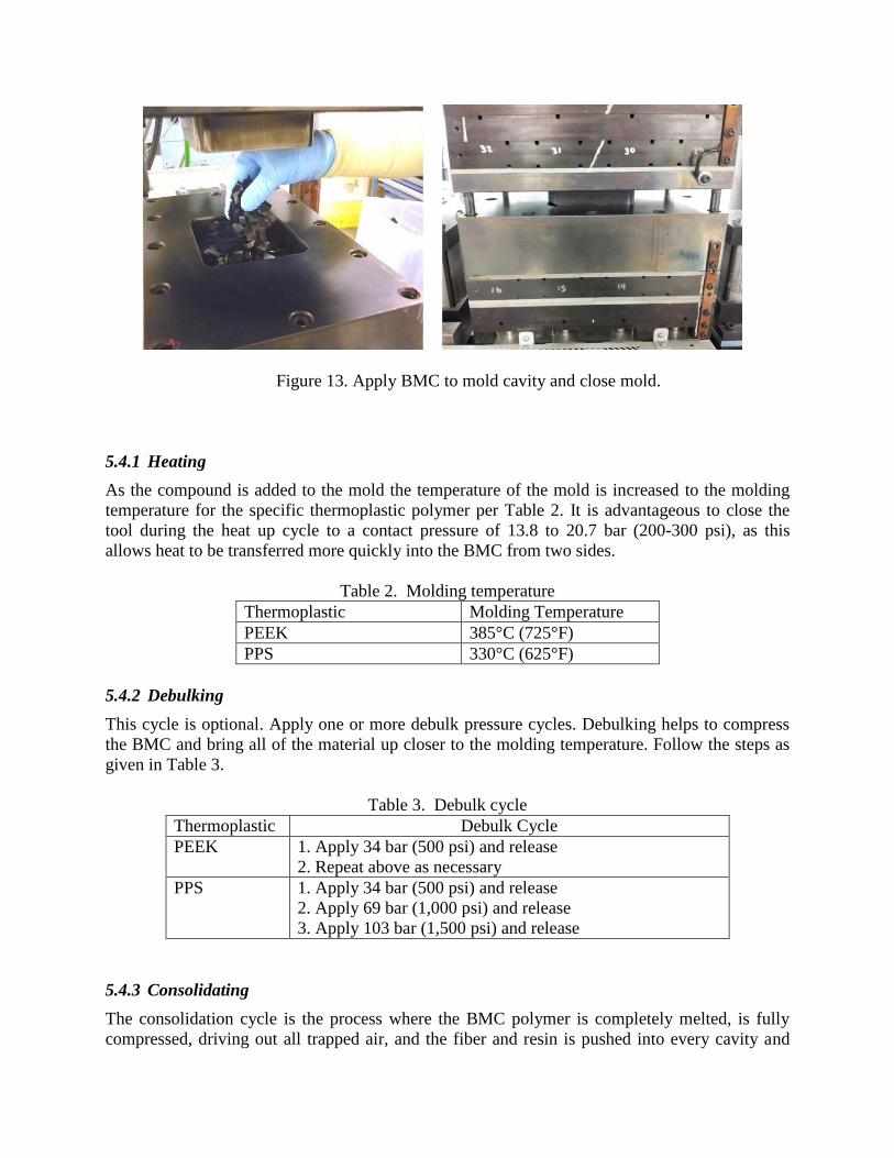
Figure 13. Apply BMC to mold cavity and close mold.
5.4.1 Heating
As the compound is added to the mold the temperature of the mold is increased to the molding
temperature for the specific thermoplastic polymer per Table 2. It is advantageous to close the
tool during the heat up cycle to a contact pressure of 13.8 to 20.7 bar (200-300 psi), as this
allows heat to be transferred more quickly into the BMC from two sides.
Table 2. Molding temperature
Thermoplastic Molding Temperature
PEEK 385°C (725°F)
PPS 330°C (625°F)
5.4.2 Debulking
This cycle is optional. Apply one or more debulk pressure cycles. Debulking helps to compress
the BMC and bring all of the material up closer to the molding temperature. Follow the steps as
given in Table 3.
Table 3. Debulk cycle
Thermoplastic Debulk Cycle
PEEK 1. Apply 34 bar (500 psi) and release
2. Repeat above as necessary
PPS 1. Apply 34 bar (500 psi) and release
2. Apply 69 bar (1,000 psi) and release
3. Apply 103 bar (1,500 psi) and release
5.4.3 Consolidating
The consolidation cycle is the process where the BMC polymer is completely melted, is fully
compressed, driving out all trapped air, and the fiber and resin is pushed into every cavity and
feature in the mold. Table 4 gives the consolidation cycle parameters. The pressure range listed
is dependent upon feature complexity and fiber length - the more complex the features and the
longer the fiber, the higher the pressure.
Table 4. Consolidation cycle
Thermoplastic Consolidation Cycle
PEEK 1. Pressurize to between 34 and 69 bar (500 and 1,000 psi),
but can be higher for more complex parts.
2. Hold until all the material has reached a minimum
temperature of 385°C (725°F)
3. Dwell for 0-2 minutes
PPS 1. Pressurize to between 34 and 103 bar (500 and 1,500
psi), but can be higher for more complex parts.
2. Hold until all the material has reached a minimum
temperature of 330°C (625°F)
3. Dwell for 0-10 minutes
5.4.4 Cooling
The cooling cycle is important for the formation of semi-crystalline molecular structures in
PEEK, PPS and PEKK. PEI in a 100% amorphous polymer and does not have any crystalline
structure, so it's cool down rates can be much faster. Crystallinity in a thermoplastic polymer
leads to better creep properties and increased chemical resistance. Table 5 shows the
recommended cooling cycles.
Table 5. Cooling cycle
Thermoplastic Cooling Cycle
PEEK 1. Hold pressure at the consolidation pressure
2. Cool part to between 5-20°C/minute. [Studies have
shown (Ref. 8) that rates of 0.5C/min. will produce 43%
crystallinity, 5°C/min. will produce 32%, and 20°C/min.
will give 25%]
3. Release pressure when part gets below the Tg of 143°C
(290°F)
PPS 1. Hold pressure at the consolidation pressure
2. Cool part to between 5-20°C/minute.
3. Release pressure when part gets below the Tg of 95°C
(203°F)
5.5 Demold and Deflash
The part can be removed from the tool when the temperature falls below the Tg of the polymer.
There will always be a small amount of flashing that needs to be removed from the part
perimeter, but note that the amount of flash is very small compared to the volume of the part. A
diamond grit file is well suited to remove the flashing and any fibers (Figure 11).
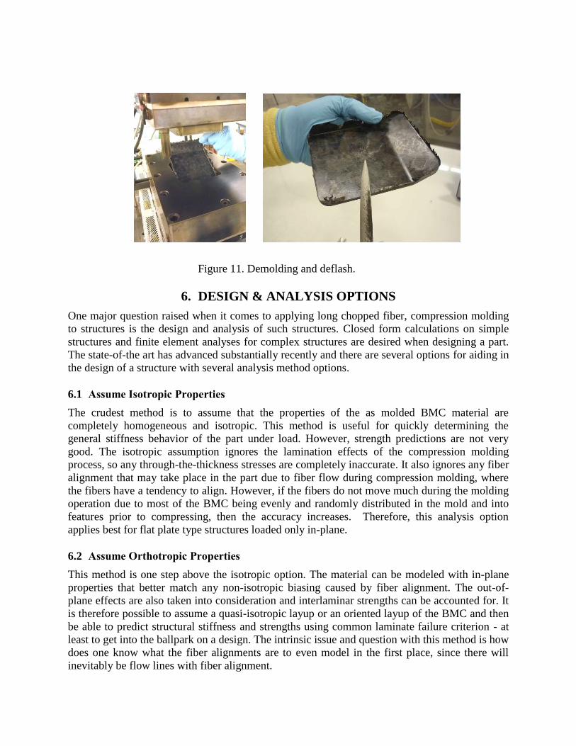
Figure 11. Demolding and deflash.
6. DESIGN & ANALYSIS OPTIONS
One major question raised when it comes to applying long chopped fiber, compression molding
to structures is the design and analysis of such structures. Closed form calculations on simple
structures and finite element analyses for complex structures are desired when designing a part.
The state-of-the art has advanced substantially recently and there are several options for aiding in
the design of a structure with several analysis method options.
6.1 Assume Isotropic Properties
The crudest method is to assume that the properties of the as molded BMC material are
completely homogeneous and isotropic. This method is useful for quickly determining the
general stiffness behavior of the part under load. However, strength predictions are not very
good. The isotropic assumption ignores the lamination effects of the compression molding
process, so any through-the-thickness stresses are completely inaccurate. It also ignores any fiber
alignment that may take place in the part due to fiber flow during compression molding, where
the fibers have a tendency to align. However, if the fibers do not move much during the molding
operation due to most of the BMC being evenly and randomly distributed in the mold and into
features prior to compressing, then the accuracy increases. Therefore, this analysis option
applies best for flat plate type structures loaded only in-plane.
6.2 Assume Orthotropic Properties
This method is one step above the isotropic option. The material can be modeled with in-plane
properties that better match any non-isotropic biasing caused by fiber alignment. The out-of-
plane effects are also taken into consideration and interlaminar strengths can be accounted for. It
is therefore possible to assume a quasi-isotropic layup or an oriented layup of the BMC and then
be able to predict structural stiffness and strengths using common laminate failure criterion - at
least to get into the ballpark on a design. The intrinsic issue and question with this method is how
does one know what the fiber alignments are to even model in the first place, since there will
inevitably be flow lines with fiber alignment.
6.3 Use State-of-the-art Predictive Methods
While there may be others under development, this author knows of two commercially available
solutions for more accurately modeling and predicting the behavior of long fiber compression
molded composite structures. Moldex3D (Ref. 9), a popular modeling tool that has been used for
years for injection molding of short fibers, has the capability to reasonably simulate the flow and
fiber alignment of thermoplastic BMC in a structure. It does not account for the fibers in the
chips being bent, but it does predict general alignments. Once the fiber alignments in the part
have been predicted they can then be imported into the Digimat (Ref. 10) solver. Digimat aligns
every random anisotropic solid element to the fiber directions imported. Digimat analyzes for
strength based upon common laminated plate failure theories but can also predict strength based
upon a multi-continuum type theory that breaks down the material strength predictions into the
separate constituents of fiber and matrix. Work is ongoing with these two codes to improve
modeling and predictions for long chopped fiber BMCs.
7. CONCLUSIONS
Long, chopped fiber, thermoplastic, compression molded composite parts are being fabricated
using a variety of BMCs. The issue of temperature control at various locations within a part
being molded has been solved using the XPress process with multi heating zone tooling.
Applications for BMC thermoplastics mainly center around replacement of metallic parts with
complex geometries and give the benefit of lighter weight, high specific strength and modulus,
and corrosion resistance. Thermoplastic BMCs give the added benefit of superior toughness,
high production throughput and inherent FST characteristics when compared to thermosets.
Difficulties encountered with designing and analyzing with these BMC materials are being
alleviated with state-of-the-art, commercially available software tools.
8. REFERENCES
1. Peterson, C., et al, Compression Molding, ASM Handbook, v21, Composites, 2001, Metals
Park, OH.
2. Black, S., Military OEM Makes the Switch from Sandwich Construction to Compression
Molding to Optimize Composite Aerospace Part, High Performance Composites, 2012,
Cincinnati, OH.
3. Beckwith, S., Thermoplastic Composite Resin Matrices, SAMPE Journal, v 44, No. 1, pp.
70-71, Jan/Feb 2008.
4. Fiberforge, Understanding Creep in Composites: Thermoplastics, FTS-002, 2008, Glenwood
Springs, CO.
5. Data Sheet, TenCate Cetex® MC1100 PPS Thermoplastic BMC, MC1100_DS_042313,
April 2013.
6. Data Sheet, TenCate Cetex® MC1200 PEEK Thermoplastic BMC, MC1200_DS_031313,
March 2013.
7. Selezneva, M., et al, Modeling of Mechanical Properties of Randomly Oriented Strand
Thermoplastic Composites, McGill University, 2014, Montreal, QC.

8. Lee, W., et al, Effects of Cooling Rate on the Crystallinity and Mechanical Properties of
Thermoplastic Composites, Journal of Reinforced Plastics and Composites 1987; 6; 2.
9. CoreTech System Co., Ltd., Moldex3d Compression Molding, vR13.0, Presentation, 2014.
10. Exstream Engineering, Digimat Material Modeling Compression Molding DLF Composites,
Presentation, 2014.