Embed Size (px)
Citation preview
8
Multiprocessors 8
en the nal
the
ntial
d of ast, the
The turning away from the conventional organization came in the middle 1960s, whlaw of diminishing returns began to take effect in the effort to increase the operatiospeed of a computer. … Electronic circuits are ultimately limited in their speed of operation by the speed of light… and many of the circuits were already operating innanosecond range.
Bouknight et al., The Illiac IV System [1972]
… sequential computers are approaching a fundamental physical limit on their potecomputational power. Such a limit is the speed of light . . .
A. L. DeCegama, The Technology of Parallel Processing, Volume I (1989)
… today’s machines… are nearing an impasse as technologies approach the speelight. Even if the components of a sequential processor could be made to work this fbest that could be expected is no more than a few million instructions per second.
Mitchell, The Transputer: The Time Is Now [1989]

8.1 Introduction 635
8.2 Characteristics of Application Domains 647
8.3 Centralized Shared-Memory Architectures 654
8.4 Distributed Shared-Memory Architectures 677
8.5 Synchronization 694
8.6 Models of Memory Consistency 708
8.7 Crosscutting Issues 721
8.8 Putting It All Together:The SGI Challenge Multiprocessor 728
8.9 Fallacies and Pitfalls 734
8.10 Concluding Remarks 740
8.11 Historical Perspective and References 745
Exercises 755
uni-ryingipro-t raten bal-ggerpro-gicalltipleing anova-985
ssueed in
As the quotations that open this chapter show, the view that advances inprocessor architecture were nearing an end has been widely held at vatimes. To counter this view, we observe that during the period 1985–95, uncessor performance growth, driven by the microprocessor, was at its highessince the first transistorized computers in the late 1950s and early 1960s. Oance, your authors believe that parallel machines will definitely have a birole in the future. This view is driven by three observations. First, since microcessors are likely to remain the dominant uniprocessor technology, the loway to improve performance beyond a single processor is by connecting mumicroprocessors together. This is likely to be more cost-effective than designcustom processor. Second, it is unclear whether the pace of architectural intion that has contributed to the rapid rate of performance growth starting in 1can be sustained indefinitely. As we saw in Chapter 4, modern multiple-iprocessors have become incredibly complex, and the increases achiev
8.1 Introduction
636
Chapter 8 Multiprocessors
min-stacle
ad-f per-
this bet
down,
e ising
re al-trade-ly en- haven thebers andsignsettled themput-rallelg ap- re-
theled toribetheseper-
o im-ears stillamshine,
performance for increasing complexity and increasing silicon seem to be diishing. Third, there appears to be slow but steady progress on the major obto widespread use of parallel machines, namely software.
Your authors, however, are extremely reluctant to predict the death ofvances in uniprocessor architecture. Indeed, we believe that the rapid rate oformance growth will continue at least into the next millennium. Whether pace of innovation can be sustained longer is difficult to predict and hard toagainst. Nonetheless, if the pace of progress in uniprocessors does slow multiprocessor architectures will become increasingly attractive.
That said, we are left with two problems. First, multiprocessor architectura large and diverse field, and much of the field is in its infancy, with ideas comand going and more architectures failing than succeeding. Given that we aready on page 636, full coverage of the multiprocessor design space and its offs would require another volume. Second, such coverage would necessaritail discussing approaches that may not stand the test of time, something welargely avoided to this point. For these reasons, we have chosen to focus omainstream of multiprocessor design: machines with small to medium numof processors (<100). Such designs vastly dominate in terms of both unitsdollars. We will pay only slight attention to the larger-scale multiprocessor despace (>100 processors). The future architecture of such machines is so unin the mid 1990s that even the viability of that marketplace is in doubt. Inpast, the high-end scientific marketplace has been dominated by vector coers (see Appendix B), which in recent times have become small-scale pavector computers (typically 4 to 16 processors). There are several contendinproaches and which, if any, will survive in the future remains unclear. We willturn to this topic briefly at the end of the chapter, in section 8.10.
A Taxonomy of Parallel Architectures
We begin this chapter with a taxonomy so that you can appreciate bothbreadth of design alternatives for multiprocessors and the context that has the development of the dominant form of multiprocessors. We briefly descthe alternatives and the rationale behind them; a longer description of how different models were born (and often died) can be found in the historical spectives at the end of the chapter.
The idea of using multiple processors both to increase performance and tprove availability dates back to the earliest electronic computers. About 30 yago, Flynn proposed a simple model of categorizing all computers that isuseful today. He looked at the parallelism in the instruction and data strecalled for by the instructions at the most constrained component of the macand placed all computers in one of four categories:
8.1 Introduction
637
.
pro-ingles in-rality
rs are
None-
sorsn theoice for
rt,ncemul-
helfamers.
pro-nect whate.
smallalizedlarges of ahas a
called
1. Single instruction stream, single data stream (SISD)—This is a uniprocessor
2. Single instruction stream, multiple data streams (SIMD)—The same instruc-tion is executed by multiple processors using different data streams. Eachcessor has its own data memory (hence multiple data), but there is a sinstruction memory and control processor, which fetches and dispatchestructions. The processors are typically special purpose, since full geneis not required.
3. Multiple instruction streams, single data stream (MISD)—No commercialmachine of this type has been built to date, but may be in the future.
4. Multiple instruction streams, multiple data streams (MIMD)—Each processorfetches its own instructions and operates on its own data. The processooften off-the-shelf microprocessors.
This is a coarse model, as some machines are hybrids of these categories.theless, it is useful to put a framework on the design space.
As discussed in the historical perspectives, many of the early multiproceswere SIMD, and the SIMD model received renewed attention in the 1980s. Ilast few years, however, MIMD has clearly emerged as the architecture of chfor general-purpose multiprocessors. Two factors are primarily responsiblethe rise of the MIMD machines:
1. MIMDs offer flexibility. With the correct hardware and software suppoMIMDs can function as single-user machines focusing on high performafor one application, as multiprogrammed machines running many tasks sitaneously, or as some combination of these functions.
2. MIMDs can build on the cost/performance advantages of off-the-smicroprocessors. In fact, nearly all multiprocessors built today use the smicroprocessors found in workstations and small, single-processor serve
Existing MIMD machines fall into two classes, depending on the number of cessors involved, which in turn dictate a memory organization and interconstrategy. We refer to the machines by their memory organization, becauseconstitutes a small or large number of processors is likely to change over tim
The first group, which we call centralized shared-memory architectures, haveat most a few dozen processors in the mid 1990s. For multiprocessors with processor counts, it is possible for the processors to share a single centrmemory and to interconnect the processors and memory by a bus. With caches, the bus and the single memory can satisfy the memory demandsmall number of processors. Because there is a single main memory that uniform access time from each processor, these machines are sometimes
638
Chapter 8 Multiprocessors
r-owss the
y. Toroces-ble to rapidessor’sutedse inurse,idth
what
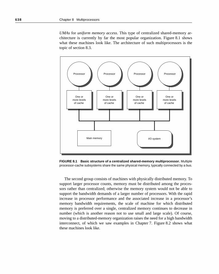
UMAs for uniform memory access. This type of centralized shared-memory achitecture is currently by far the most popular organization. Figure 8.1 shwhat these machines look like. The architecture of such multiprocessors itopic of section 8.3.
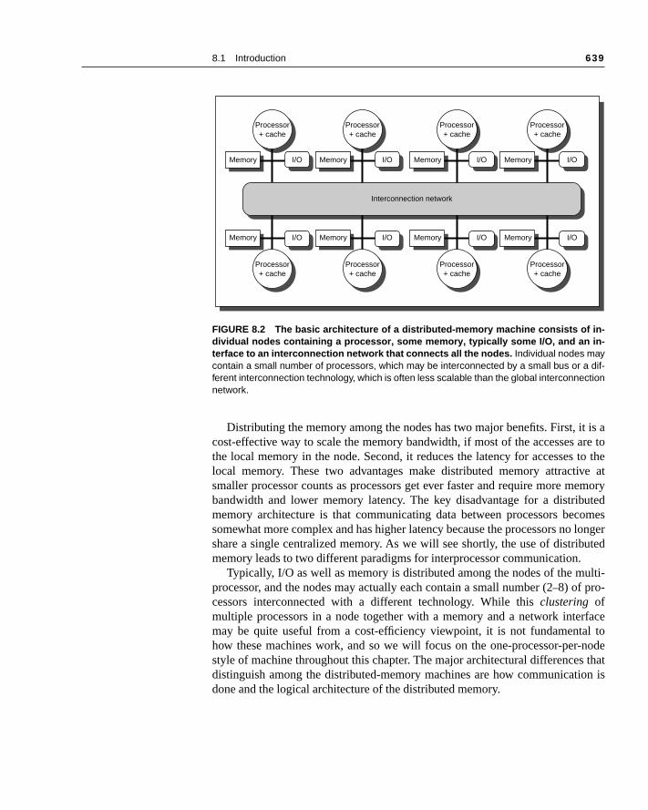
The second group consists of machines with physically distributed memorsupport larger processor counts, memory must be distributed among the psors rather than centralized; otherwise the memory system would not be asupport the bandwidth demands of a larger number of processors. With theincrease in processor performance and the associated increase in a procmemory bandwidth requirements, the scale of machine for which distribmemory is preferred over a single, centralized memory continues to decreanumber (which is another reason not to use small and large scale). Of comoving to a distributed-memory organization raises the need for a high bandwinterconnect, of which we saw examples in Chapter 7. Figure 8.2 shows these machines look like.
FIGURE 8.1 Basic structure of a centralized shared-memory multiprocessor. Multipleprocessor-cache subsystems share the same physical memory, typically connected by a bus.
Processor
One ormore levelsof cache
ProcessorProcessor Processor
Main memory I/O system
One ormore levelsof cache
One ormore levelsof cache
One ormore levelsof cache
8.1 Introduction
639
t is are to
to thee atemoryutedomes longeruted
ulti-
rfacel to-node that
on is
Distributing the memory among the nodes has two major benefits. First, icost-effective way to scale the memory bandwidth, if most of the accesses athe local memory in the node. Second, it reduces the latency for accesseslocal memory. These two advantages make distributed memory attractivsmaller processor counts as processors get ever faster and require more mbandwidth and lower memory latency. The key disadvantage for a distribmemory architecture is that communicating data between processors becsomewhat more complex and has higher latency because the processors noshare a single centralized memory. As we will see shortly, the use of distribmemory leads to two different paradigms for interprocessor communication.
Typically, I/O as well as memory is distributed among the nodes of the mprocessor, and the nodes may actually each contain a small number (2–8) of pro-cessors interconnected with a different technology. While this clustering ofmultiple processors in a node together with a memory and a network intemay be quite useful from a cost-efficiency viewpoint, it is not fundamentahow these machines work, and so we will focus on the one-processor-perstyle of machine throughout this chapter. The major architectural differencesdistinguish among the distributed-memory machines are how communicatidone and the logical architecture of the distributed memory.
FIGURE 8.2 The basic architecture of a distributed-memory machine consists of in-dividual nodes containing a processor, some memory, typically some I/O, and an in-terface to an interconnection network that connects all the nodes. Individual nodes maycontain a small number of processors, which may be interconnected by a small bus or a dif-ferent interconnection technology, which is often less scalable than the global interconnectionnetwork.
Memory I/O
Interconnection network
Memory I/O Memory I/O
Processor+ cache
Processor+ cache
Processor+ cache
Processor+ cache
Memory I/O
Memory I/O Memory I/O Memory I/O Memory I/O
Processor+ cache
Processor+ cache
Processor+ cache
Processor+ cache
640
Chapter 8 Multiprocessors
oriese ar-dataas oneade byrights.
to the
,nown
f a
paces sucho twole is
ter, a local canoset or
ciatedat ad-pera-
hsing
called
sages dis-rate onerformof as a
es- ac-reply
efore
Models for Communication and Memory Architecture
As discussed earlier, any large-scale multiprocessor must use multiple memthat are physically distributed with the processors. There are two alternativchitectural approaches that differ in the method used for communicating among processors. The physically separate memories can be addressed logically shared address space, meaning that a memory reference can be many processor to any memory location, assuming it has the correct access These machines are called distributed shared-memory (DSM) or scalable shared-memory architectures. The term shared memory refers to the fact that the addressspace is shared; that is, the same physical address on two processors referssame location in memory. Shared memory does not mean that there is a singlecentralized memory. In contrast to the centralized memory machines, also kas UMAs (uniform memory access), the DSM machines are also called NUMAs,non-uniform memory access, since the access time depends on the location odata word in memory.
Alternatively, the address space can consist of multiple private address sthat are logically disjoint and cannot be addressed by a remote processor. Inmachines, the same physical address on two different processors refers tdifferent locations in two different memories. Each processor-memory moduessentially a separate computer; therefore these machines have been calledmulti-computers. As pointed out in the concluding remarks of the previous chapthese machines can even be completely separate computers connected onarea network. For applications that require little or no communication andmake use of separate memories, such clusters of machines, whether in a clon desktops, can form a very cost-effective approach.
With each of these organizations for the address space, there is an assocommunication mechanism. For a machine with a shared address space, thdress space can be used to communicate data implicitly via load and store otions; hence the name shared memory for such machines. For a machine witmultiple address spaces, communication of data is done by explicitly pasmessages among the processors. Therefore, these machines are oftenmessage passing machines.
In message passing machines, communication occurs by sending mesthat request action or deliver data just as with the simple network protocolscussed in section 7.2. For example, if one processor wants to access or opedata in a remote memory, it can send a message to request the data or to psome operation on the data. In such cases, the message can be thought remote procedure call (RPC). When the destination processor receives the msage, either by polling for it or via an interrupt, it performs the operation orcess on behalf of the remote processor and returns the result with a message. This type of message passing is also called synchronous, since the initi-ating processor sends a request and waits until the reply is returned b
8.1 Introduction
641
tails ofreturn
therg dataan beis of-ender
s to checkg re-t con-ferent pass- pro-rface.
someeter-gleh byHowth ofed inr in-of a limitpan-vent, limitsuni-
w
nec-iving
continuing. Software systems have been constructed to encapsulate the desending and receiving messages, including passing complex arguments or values, presenting a clean RPC facility to the programmer.
Communication can also occur from the viewpoint of the writer of data rathan the reader, and this can be more efficient when the processor producinknows which other processors will need the data. In such cases, the data csent directly to the consumer process without having to be requested first. It ten possible to perform such message sends asynchronously, allowing the sprocess to continue immediately. Often the receiver will want to block if it triereceive the message before it has arrived; in other cases, the reader maywhether a message is pending before actually trying to perform a blockinceive. Also the sender must be prepared to block if the receiver has not yesumed an earlier message. The message passing facilities offered in difmachines are fairly diverse. To ease program portability, standard messageing libraries (for example, message passing interface, or MPI) have beenposed. Such libraries sacrifice some performance to achieve a common inte
Performance Metrics for Communication MechanismsThree performance metrics are critical in any communication mechanism:
1. Communication bandwidth—Ideally the communication bandwidth is limitedby processor, memory, and interconnection bandwidths, rather than by aspect of the communication mechanism. The bisection bandwidth is dmined by the interconnection network. The bandwidth in or out of a sinnode, which is often as important as bisection bandwidth, is affected botthe architecture within the node and by the communication mechanism. does the communication mechanism affect the communication bandwida node? When communication occurs, resources within the nodes involvthe communication are tied up or occupied, preventing other outgoing ocoming communication. When this occupancy is incurred for each word message, it sets an absolute limit on the communication bandwidth. Thisis often lower than what the network or memory system can provide. Occucy may also have a component that is incurred for each communication esuch as an incoming or outgoing request. In the latter case, the occupancythe communication rate, and the impact of the occupancy on overall commcation bandwidth depends on the size of the messages.
2. Communication latency—Ideally the latency is as low as possible. As we sain Chapter 7, communication latency is equal to
Sender overhead + Time of flight + Transmission time + Receiver overhead
Time of flight is preset and transmission time is determined by the intercontion network. The software and hardware overheads in sending and rece
642
Chapter 8 Multiprocessors
nd itsnce it di-using manyancych-s thectiony theall. Al-m forf com-
yn?
s antimet forareddea, pro-ation
of the com- a di-hes.ing
nisms, andcienttion
emory
zed
messages are largely determined by the communication mechanism aimplementation. Why is latency crucial? Latency affects both performaand how easy it is to program a multiprocessor. Unless latency is hidden,rectly affects performance either by tying up processor resources or by cathe processor to wait. Overhead and occupancy are closely related, sinceforms of overhead also tie up some part of the node, incurring an occupcost, which in turn limits bandwidth. Key features of a communication meanism may directly affect overhead and occupancy. For example, how idestination address for a remote communication named, and how is proteimplemented? When naming and protection mechanisms are provided bprocessor, as in a shared address space, the additional overhead is smternatively, if these mechanisms must be provided by the operating systeeach communication, this increases the overhead and occupancy costs omunication, which in turn reduce bandwidth and increase latency.
3. Communication latency hiding—How well can the mechanism hide latency boverlapping communication with computation or with other communicatioAlthough measuring this is not as simple as measuring the first two, it iimportant characteristic that can be quantified by measuring the running on machines with the same communication latency but different supporlatency hiding. We will see examples of latency hiding techniques for shmemory in sections 8.6 and 8.7. While hiding latency is certainly a good iit poses an additional burden on the software system and ultimately on thegrammer. Furthermore, the amount of latency that can be hidden is applicdependent. Thus it is usually best to reduce latency wherever possible.
Each of these performance measures is affected by the characteristics communications needed in the application. The size of the data items beingmunicated is the most obvious, since it affects both latency and bandwidth inrect way, as well as affecting the efficacy of different latency hiding approacSimilarly, the regularity in the communication patterns affects the cost of namand protection, and hence the communication overhead. In general, mechathat perform well with smaller as well as larger data communication requestsirregular as well as regular communication patterns, are more flexible and effifor a wider class of applications. Of course, in considering any communicamechanism, designers must consider cost as well as performance.
Advantages of Different Communication MechanismsEach of these communication mechanisms has its advantages. For shared-mcommunication, advantages include
■ Compatibility with the well-understood mechanisms in use in centralimultiprocessors, which all use shared-memory communication.
8.1 Introduction
643
rs arelify
mu-andthan
f re-aredr ac-
ared-
ten-om-note is
hard-assingntially
nted byficul-itrarynede ei-
lties,
ssing, alle ad-renc-
small soft-
soft-is the soft- hier-tual
■ Ease of programming when the communication patterns among processocomplex or vary dynamically during execution. Similar advantages simpcompiler design.
■ Lower overhead for communication and better use of bandwidth when comnicating small items. This arises from the implicit nature of communication the use of memory mapping to implement protection in hardware, rather through the operating system.
■ The ability to use hardware-controlled caching to reduce the frequency omote communication by supporting automatic caching of all data, both shand private. As we will see, caching reduces both latency and contention focessing shared data.
The major advantages for message-passing communication include
■ The hardware can be simpler, especially by comparison with a scalable shmemory implementation that supports coherent caching of remote data.
■ Communication is explicit, forcing programmers and compilers to pay attion to communication. This process may be painful for programmers and cpiler writers, but it simplifies the abstraction of what is costly and what is and focuses attention on costly communication. (If you think this advantaga mixed bag, that’s OK; so do many others.)
Of course, the desired communication model can be created on top of a ware model that supports either of these mechanisms. Supporting message pon top of shared memory is considerably easier: Because messages essesend data from one memory to another, sending a message can be implemedoing a copy from one portion of the address space to another. The major difties arise from dealing with messages that may be misaligned and of arblength in a memory system that is normally oriented toward transferring aligblocks of data organized as cache blocks. These difficulties can be overcomther with small performance penalties in software or with essentially no penausing a small amount of hardware support.
Supporting shared memory efficiently on top of hardware for message pais much more difficult. Without explicit hardware support for shared memoryshared-memory references need to involve the operating system to providdress translation and memory protection, as well as to translate memory refees into message sends and receives. Loads and stores usually moveamounts of data, so the high overhead of handling these communications inware severely limits the range of applications for which the performance of ware-based shared memory is acceptable. An ongoing area of research exploration of when a software-based model is acceptable and whether aware-based mechanism is usable for the highest level of communication in aarchically structured system. One promising direction is the use of vir

644
Chapter 8 Multiprocessors
tioninesgnersilt witheen
90s.rgest
nd hy-f theinflu-a dis- and
mi-mo-tail atatural
e dis-dress
ro-e intions.s in
memory mechanisms to share objects at the page level, a technique called sharedvirtual memory; we discuss this approach in section 8.7.
In distributed-memory machines, the memory model and communicamechanisms distinguish the machines. Originally, distributed-memory machwere built with message passing, since it was clearly simpler and many desiand researchers did not believe that a shared address space could be budistributed memory. More recently, shared-memory communication has bsupported in virtually every machine designed for the latter half of the 19What hardware communication mechanisms will be supported in the very lamachines (called massively parallel processors, or MPPs), which typically havemore than 100 processors, is unclear; shared memory, message passing, abrid approaches are all contenders. Despite the symbolic importance oMPPs, such machines are a small portion of the market and have little or no ence on the mainstream machines with tens of processors. We will return to cussion of the possibilities and trends for MPPs in the concluding remarkshistorical perspectives at the end of this chapter.
Although centralized memory machines using a bus interconnect still donate in terms of market size, long-term technical trends favor distributing mery even in moderate-scale machines; we’ll discuss these issues in more dethe end of this chapter. These distributed shared-memory machines are a nextension of the centralized multiprocessors that dominate the market, so wcuss these architectures in section 8.4. One important question that we adthere is the question of caching and coherence.
Challenges of Parallel Processing
Two important hurdles, both explainable with Amdahl’s Law, make parallel pcessing challenging. The first has to do with the limited parallelism availablprograms and the second arises from the relatively high cost of communicaLimitations in available parallelism make it difficult to achieve good speedupparallel machines, as our first Example shows.
E X A M P L E Suppose you want to achieve a speedup of 80 with 100 processors. What fraction of the original computation can be sequential?
A N S W E R Amdahl’s Law is
Speedup =1
FractionenhancedSpeedupenhanced----------------------------------------- (1 – Fractionenhanced )+
------------------------------------------------------------------------------------------------------
8.1 Introduction
645
s in aces-
, de-ork,
to re-
ider
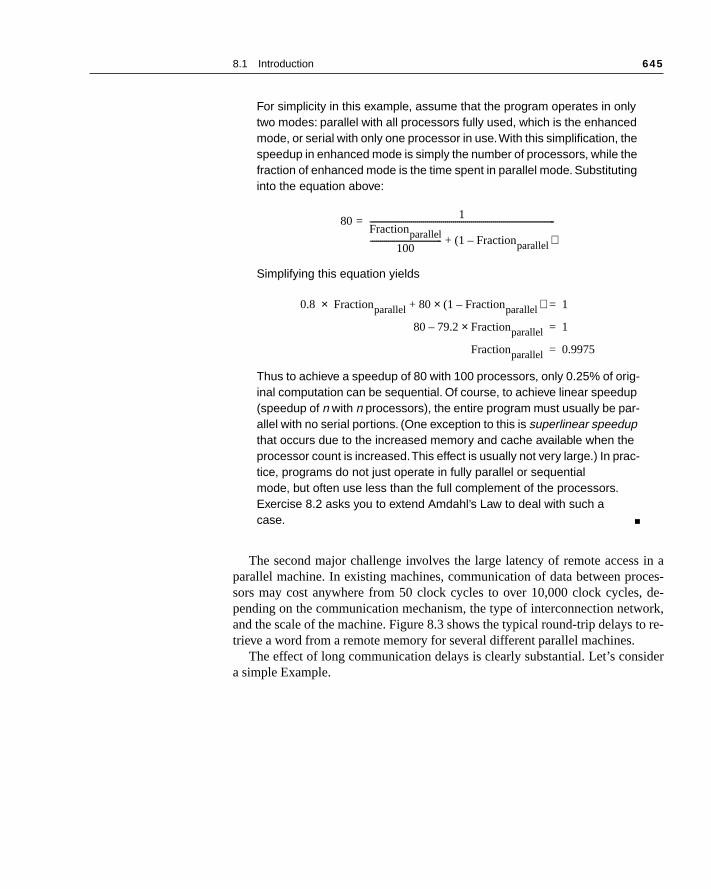
For simplicity in this example, assume that the program operates in only two modes: parallel with all processors fully used, which is the enhanced mode, or serial with only one processor in use. With this simplification, the speedup in enhanced mode is simply the number of processors, while the fraction of enhanced mode is the time spent in parallel mode. Substituting into the equation above:
Simplifying this equation yields
Thus to achieve a speedup of 80 with 100 processors, only 0.25% of orig-inal computation can be sequential. Of course, to achieve linear speedup (speedup of n with n processors), the entire program must usually be par-allel with no serial portions. (One exception to this is superlinear speedup that occurs due to the increased memory and cache available when the processor count is increased. This effect is usually not very large.) In prac-tice, programs do not just operate in fully parallel or sequential mode, but often use less than the full complement of the processors. Exercise 8.2 asks you to extend Amdahl’s Law to deal with such a case. ■
The second major challenge involves the large latency of remote accesparallel machine. In existing machines, communication of data between prosors may cost anywhere from 50 clock cycles to over 10,000 clock cyclespending on the communication mechanism, the type of interconnection netwand the scale of the machine. Figure 8.3 shows the typical round-trip delays trieve a word from a remote memory for several different parallel machines.
The effect of long communication delays is clearly substantial. Let’s consa simple Example.
80 1
Fractionparallel100
------------------------------------ (1 – Fractionparallel )+
---------------------------------------------------------------------------------------------=
0.8 Fractionparallel× 80 (1 – Fractionparallel× )+ 1=
80 79.2 Fractionparallel×– 1=
Fractionparallel 0.9975=

646
Chapter 8 Multiprocessors
E X A M P L E Suppose we have an application running on a 32-processor machine, which has a 2000-ns time to handle reference to a remote memory. For this application, assume that all the references except those involving communication hit in the local memory hierarchy, which may be only slightly pessimistic. Processors are stalled on a remote request, and the cycle time of the processors is 10 ns. If the base CPI (assuming that all references hit in the cache) is 1.0, how much faster is the machine if there is no communication versus if 0.5% of the instructions involve a remote communication reference?
A N S W E R The effective CPI for the machine with 0.5% remote references is
The Remote request cost is
Hence we can compute the CPI:
CPI = 1.0 + 0.5% × 200 = 2.0
The machine with all local references is 2.0/1.0 = 2 times faster. In prac-tice, the performance analysis is much more complex, since some fraction
MachineCommunication
mechanismInterconnection
networkProcessor
countTypical remote
memory access time
SPARCCenter Shared memory Bus ≤ 20 1 µs
SGI Challenge Shared memory Bus ≤ 36 1 µs
Cray T3D Shared memory 3D torus 32–2048 1 µs
Convex Exemplar Shared memory Crossbar + ring 8–64 2 µs
KSR-1 Shared memory Hierarchical ring 32–256 2–6 µs
CM-5 Message passing Fat tree 32–1024 10 µs
Intel Paragon Message passing 2D mesh 32–2048 10–30 µs
IBM SP-2 Message passing Multistage switch 2–512 30–100 µs
FIGURE 8.3 Typical remote access times to retrieve a word from a remote memory. In the case of shared-memorymachines, this is the remote load time. For a message-passing machine, the value shown is the time to send a messageand reply to the message.
CPI Base CPI Remote request rate Remote request cost×+=
1.0 0.5% Remote request cost×+=
Remote access costCycle time
---------------------------------------------- 2000 ns10 ns
-------------------= 200 cycles=
8.2 Characteristics of Application Domains
647
uni-m ofwithact ofgram-eitherecha- try to
g re- how a co-use itbot-isten-ul toth fortionsallel
plica-ns.aches
rallelch aspend fac- spa-e timefor-
s ofed
of the noncommunication references will miss in the local hierarchy and the remote access time does not have a single constant value. For exam-ple, the cost of a remote reference could be quite a bit worse, since con-tention caused by many references trying to use the global interconnect can lead to increased delays. ■
These problems—insufficient parallelism and long latency remote commcation—are the two biggest challenges in using multiprocessors. The probleinadequate application parallelism must be attacked primarily in software new algorithms that can have better parallel performance. Reducing the implong remote latency can be attacked both by the architecture and by the promer. For example, we can reduce the frequency of remote accesses with hardware mechanisms, such as caching shared data, or with software mnisms, such as restructuring the data to make more accesses local. We cantolerate the latency by using prefetch, which we examined in Chapter 5.
Much of this chapter focuses on techniques for reducing the impact of lonmote communication latency. For example, sections 8.3 and 8.4 discusscaching can be used to reduce remote access frequency, while maintainingherent view of memory. Section 8.5 discusses synchronization, which, becainherently involves interprocessor communication, is an additional potential tleneck. Section 8.6 talks about latency hiding techniques and memory conscy models for shared memory. Before we wade into these topics, it is helpfhave some understanding of the characteristics of parallel applications, bobetter comprehension of the results we show using some of these applicaand to gain a better understanding of the challenges in writing efficient parprograms.
In earlier chapters, we examined the performance and characteristics of aptions with only a small amount of insight into the structure of the applicatioFor understanding the key elements of uniprocessor performance, such as cand pipelining, general knowledge of an application is often adequate. In paprocessing, however, the additional performance-critical characteristics—suload balance, synchronization, and sensitivity to memory latency—often deon high-level characteristics of the application. These characteristics includetors like how data is distributed, the structure of a parallel algorithm, and thetial and temporal access patterns to data. Therefore at this point we take thto examine the two different classes of workloads that we will use for permance analysis in this chapter.
This section briefly describes the characteristics of two different domainmultiprocessor workloads: individual parallel programs and multiprogramm
8.2 Characteristics of Application Domains
648
Chapter 8 Multiprocessors
oadsg real-ces-
cess,tionsre isf data-tipro-ve to
pu-n LU tech- typ-all
ecific
whichWeir ba- the data single
c- to
ver-ecu-
or are
dataonlye six
workloads with operating systems included. Other major classes of worklare databases, fileservers, and transaction processing systems. Constructinistic versions of such workloads and accurately measuring them on multiprosors, including any OS activity, is an extremely complex and demanding proat the edge of what we can do with performance modeling tools. Future ediof this book may contain characterizations of such workloads. Happily, thesome evidence that the parallel processing and memory system behaviors obase and transaction processing workloads are similar to those of large mulgrammed workloads, which include the OS activity. For the present, we habe content with examining such a multiprogramming workload.
Parallel Applications
Our parallel applications workload consists of two applications and two comtational kernels. The kernels are an FFT (fast Fourier transformation) and adecomposition, which were chosen because they represent commonly usedniques in a wide variety of applications and have performance characteristicsical of many parallel scientific applications. In addition, the kernels have smcode segments whose behavior we can understand and directly track to sparchitectural characteristics.
The two applications that we use in this chapter are Barnes and Ocean, represent two important but very different types of parallel computation. briefly describe each of these applications and kernels and characterize thesic behavior in terms of parallelism and communication. We describe howproblem is decomposed for a distributed shared-memory machine; certaindecompositions that we describe are not necessary on machines that have acentralized memory.
The FFT Kernel The fast Fourier transform (FFT) is the key kernel in applications that use spetral methods, which arise in fields ranging from signal processing to fluid flowclimate modeling. The FFT application we study here is a one-dimensionalsion of a parallel algorithm for a complex-number FFT. It has a sequential extion time for n data points of n log n. The algorithm uses a high radix (equal t
) that minimizes communication. The measurements shown in this chaptecollected for a million-point input data set.
There are three primary data structures: the input and output arrays of thebeing transformed and the roots of unity matrix, which is precomputed and read during the execution. All arrays are organized as square matrices. Thsteps in the algorithm are as follows:
1. Transpose data matrix.
2. Perform 1D FFT on each row of data matrix.
n

8.2 Characteristics of Application Domains
649
the
ces-in itsvilye al-
o-alls as-placeds onestem.chepatial
ensetion,
-ads
al- thecachel parts
ica-iling:
theon is
and
redks are
3. Multiply the roots of unity matrix by the data matrix and write the result in data matrix.
4. Transpose data matrix.
5. Perform 1D FFT on each row of data matrix.
6. Transpose data matrix.
The data matrices and the roots of unity matrix are partitioned among prosors in contiguous chunks of rows, so that each processor’s partition falls own local memory. The first row of the roots of unity matrix is accessed heaby all processors and is often replicated, as we do, during the first step of thgorithm just shown.
The only communication is in the transpose phases, which require all-tcommunication of large amounts of data. Contiguous subcolumns in the rowsigned to a processor are grouped into blocks, which are transposed and into the proper location of the destination matrix. Every processor transposeblock locally and sends one block to each of the other processors in the syAlthough there is no reuse of individual words in the transpose, with long cablocks it makes sense to block the transpose to take advantage of the slocality afforded by long blocks in the source matrix.
The LU KernelLU is an LU factorization of a dense matrix and is representative of many dlinear algebra computations, such as QR factorization, Cholesky factorizaand eigenvalue methods. For a matrix of size n × n the running time is n3 and theparallelism is proportional to n2. Dense LU factorization can be performed efficiently by blocking the algorithm, using the techniques in Chapter 5, which leto highly efficient cache behavior and low communication. After blocking thegorithm, the dominant computation is a dense matrix multiply that occurs ininnermost loop. The block size is chosen to be small enough to keep the miss rate low, and large enough to reduce the time spent in the less paralleof the computation. Relatively small block sizes (8 × 8 or 16 × 16) tend to satisfyboth criteria. Two details are important for reducing interprocessor communtion. First, the blocks of the matrix are assigned to processors using a 2D tthe (where each block is B × B) matrix of blocks is allocated by laying agrid of size over the matrix of blocks in a cookie-cutter fashion until all blocks are allocated to a processor. Second, the dense matrix multiplicatiperformed by the processor that owns the destination block. With this blockingand allocation scheme, communication during the reduction is both regularpredictable. For the measurements in this chapter, the input is a 512 × 512 matrixand a block of 16 × 16 is used.
A natural way to code the blocked LU factorization of a 2D matrix in a shaaddress space is to use a 2D array to represent the matrix. Because bloc
nB--- n
B---×
p p×

650 Chapter 8 Multiprocessors
resss ofd to a the
and
g a
s in-educeter-e offlgo-t arellec-anyec- tree.
ldren)nts the
s, thehe nett theif theis “farroxi-enter masssited.nces,nates crite-f the
be-king
ity of
allocated in a tiled decomposition, and a block is not contiguous in the addspace in a 2D array, it is very difficult to allocate blocks in the local memoriethe processors that own them. The solution is to ensure that blocks assigneprocessor are allocated locally and contiguously by using a 4D array (withfirst two dimensions specifying the block number in the 2D grid of blocks, the next two specifying the element in the block).
The Barnes ApplicationBarnes is an implementation of the Barnes-Hut n-body algorithm solvinproblem in galaxy evolution. N-body algorithms simulate the interaction amonga large number of bodies that have forces interacting among them. In thistance the bodies represent collections of stars and the force is gravity. To rthe computational time required to model completely all the individual inactions among the bodies, which grow as n2, n-body algorithms take advantagof the fact that the forces drop off with distance. (Gravity, for example, dropsas 1/d2, where d is the distance between the two bodies.) The Barnes-Hut arithm takes advantage of this property by treating a collection of bodies tha“far away” from another body as a single point at the center of mass of the cotion and with mass equal to the collection. If the body is far enough from body in the collection, then the error introduced will be negligible. The colltions are structured in a hierarchical fashion, which can be represented in aThis algorithm yields an n log n running time with parallelism proportional to n.
The Barnes-Hut algorithm uses an octree (each node has up to eight chito represent the eight cubes in a portion of space. Each node then represecollection of bodies in the subtree rooted at that node, which we call a cell. Be-cause the density of space varies and the leaves represent individual bodiedepth of the tree varies. The tree is traversed once per body to compute tforce acting on that body. The force-calculation algorithm for a body starts aroot of the tree. For every node in the tree it visits, the algorithm determines center of mass of the cell represented by the subtree rooted at the node enough away” from the body. If so, the entire subtree under that node is appmated by a single point at the center of mass of the cell, and the force this cof mass exerts on the body is computed. On the other hand, if the center ofis not far enough away, the cell must be “opened” and each of its subtrees viThe distance between the body and the cell, together with the error toleradetermines which cells must be opened. This force calculation phase domithe execution time. This chapter takes measurements using 16K bodies; therion for determining whether a cell needs to be opened is set to the middle orange typically used in practice.
Obtaining effective parallel performance on Barnes-Hut is challenging cause the distribution of bodies is nonuniform and changes over time, mapartitioning the work among the processors and maintenance of good local
8.2 Characteristics of Application Domains 651
wly;celln thebtree.e will
a sub-), thee workst onn, weg thelityf dataon of
e flowue to
y up-
ids.prox- con-ints.tionrror at to anest
o thes (ascorre-gnedan in-ncenize at
whenarest-
reference difficult. We are helped by two properties: the system evolves sloand because gravitational forces fall off quickly, with high probability, each requires touching a small number of other cells, most of which were used olast time step. The tree can be partitioned by allocating each processor a suMany of the accesses needed to compute the force on a body in the subtrebe to other bodies in the subtree. Since the amount of work associated with tree varies (cells in dense portions of space will need to access more cellssize of the subtree allocated to a processor is based on some measure of thit has to do (e.g., how many other cells does it need to visit), rather than juthe number of nodes in the subtree. By partitioning the octree representatiocan obtain good load balance and good locality of reference, while keepinpartitioning cost low. Although this partitioning scheme results in good locaof reference, the resulting data references tend to be for small amounts oand are unstructured. Thus this scheme requires an efficient implementatishared-memory communication.
The Ocean ApplicationOcean simulates the influence of eddy and boundary currents on large-scalin the ocean. It uses a restricted red-black Gauss-Seidel multigrid techniqsolve a set of elliptical partial differential equations. Red-black Gauss-Seidel isan iteration technique that colors the points in the grid so as to consistentldate each point based on previous values of the adjacent neighbors. Multigridmethods solve finite difference equations by iteration using hierarchical grEach grid in the hierarchy has fewer points than the grid below, and is an apimation to the lower grid. A finer grid increases accuracy and thus the rate ofvergence, while requiring more execution time, since it has more data poWhether to move up or down in the hierarchy of grids used for the next iterais determined by the rate of change of the data values. The estimate of the eevery time-step is used to decide whether to stay at the same grid, movecoarser grid, or move to a finer grid. When the iteration converges at the filevel, a solution has been reached. Each iteration has n2 work for an n × n gridand the same amount of parallelism.
The arrays representing each grid are dynamically allocated and sized tparticular problem. The entire ocean basin is partitioned into square subgridclose as possible) that are allocated in the portion of the address space sponding to the local memory of the individual processors, which are assiresponsibility for the subgrid. For the measurements in this chapter we use put that has 130 × 130 grid points. There are five steps in a time iteration. Sidata are exchanged between the steps, all the processors present synchrothe end of each step before proceeding to the next. Communication occursthe boundary points of a subgrid are accessed by the adjacent subgrid in neneighbor fashion.
652 Chapter 8 Multiprocessors
theica-ctionom-singica- prob-counten in- the
nica-utatione. Forunt ofnica-mpu-tione the
di-risesrs. Thisds tooces-d pro-
ork-twompilens forg 787B of
h in- re-only also
Computation/Communication for the Parallel ProgramsA key characteristic in determining the performance of parallel programs isratio of computation to communication. If the ratio is high, it means the appltion has lots of computation for each datum communicated. As we saw in se8.1, communication is the costly part of parallel computing; therefore high cputation-to-communication ratios are very beneficial. In a parallel procesenvironment, we are concerned with how the ratio of computation to communtion changes as we increase either the number of processors, the size of thelem, or both. Knowing how the ratio changes as we increase the processor sheds light on how well the application can be sped up. Because we are oftterested in running larger problems, it is vital to understand how changingdata set size affects this ratio.
To understand what happens quantitatively to the computation-to-commution ratio as we add processors, consider what happens separately to compand to communication as we either add processors or increase problem sizthese applications Figure 8.4 shows that as we add processors, the amocomputation per processor falls proportionately and the amount of commution per processor falls more slowly. As we increase the problem size, the cotation scales as the O( ) complexity of the algorithm dictates. Communicascaling is more complex and depends on details of the algorithm; we describbasic phenomena for each application in the caption of Figure 8.4.
The overall computation-to-communication ratio is computed from the invidual growth rate in computation and communication. In general, this rate slowly with an increase in data set size and decreases as we add processoreminds us that performing a fixed-size problem with more processors leaincreasing inefficiencies because the amount of communication among prsors grows. It also tells us how quickly we must scale data set size as we adcessors, to keep the fraction of time in communication fixed.
Multiprogramming and OS Workload
For small-scale multiprocessors we will also look at a multiprogrammed wload consisting of both user activity and OS activity. The workload used is independent copies of the compile phase of the Andrew benchmark. The cophase consists of a parallel make using eight processors. The workload ru5.24 seconds on eight processors, creating 203 processes and performindisk requests on three different file systems. The workload is run with 128 Mmemory, and no paging activity takes place.
The workload has three distinct phases: compiling the benchmarks, whicvolves substantial compute activity; installing the object files in a library; andmoving the object files. The last phase is completely dominated by I/O and two processes are active (one for each of the runs). In the middle phase, I/Oplays a major role and the processes are largely idle.

8.2 Characteristics of Application Domains 653
nt ine per-e the
k,
k,
e
k
e
Because both idle time and instruction cache performance are importathis workload, we examine these two issues here, focusing on the data cachformance later in the chapter. For the workload measurements, we assumfollowing memory and I/O systems:
ApplicationScaling of
computation Scaling of
communicationScaling of computation-
to-communication
FFT
LU
BarnesApproximately Approximately
Ocean
FIGURE 8.4 Scaling of computation, of communication, and of the ratio are criticalfactors in determining performance on parallel machines. In this table p is the increasedprocessor count and n is the increased data set size. Scaling is on a per-processor basis. Thecomputation scales up with n at the rate given by O( ) analysis and scales down linearly as pis increased. Communication scaling is more complex. In FFT all data points must interact,so communication increases with n and decreases with p. In LU and Ocean, communicationis proportional to the boundary of a block, so it scales with data set size at a rate proportionalto the side of a square with n points, namely ; for the same reason communication in thesetwo applications scales inversely to . Barnes has the most complex scaling properties.Because of the fall-off of interaction between bodies, the basic number of interactions amongbodies, which require communication, scales as . An additional factor of log n is neededto maintain the relationships among the bodies. As processor count is increased, communi-cation scales inversely to .
I/O system Memory
Level 1 instruction cache 32K bytes, two-way set associative with a 64-byte blocone clock cycle hit time
Level 1 data cache 32K bytes, two-way set associative with a 32-byte blocone clock cycle hit time
Level 2 cache 1M bytes unified, two-way set associative with a 128-bytblock, hit time 10 clock cycles
Main memory Single memory on a bus with an access time of 100 cloccycles
Disk system Fixed access latency of 3 ms (less than normal to reducidle time)
n nlogp
-------------- np--- nlog
np--- n
p------- n
p-------
n nlogp
-------------- n nlog( )p
----------------------- n
p-------
np--- n
p------- n
p-------
np
n
p
654 Chapter 8 Multiprocessors
ssorsents:syn-l—
s action variestion sizes.
mall on-ure,
s.
ly re-and-
ay bebinedners
single
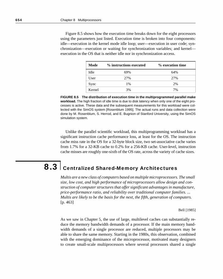
Figure 8.5 shows how the execution time breaks down for the eight proceusing the parameters just listed. Execution time is broken into four componidle—execution in the kernel mode idle loop; user—execution in user code; chronization—execution or waiting for synchronization variables; and kerneexecution in the OS that is neither idle nor in synchronization access.
Unlike the parallel scientific workload, this multiprogramming workload hasignificant instruction cache performance loss, at least for the OS. The instrucache miss rate in the OS for a 32-byte block size, two set-associative cachefrom 1.7% for a 32-KB cache to 0.2% for a 256-KB cache. User-level, instruccache misses are roughly one-sixth of the OS rate, across the variety of cache
Multis are a new class of computers based on multiple microprocessors. The ssize, low cost, and high performance of microprocessors allow design and cstruction of computer structures that offer significant advantages in manufactprice-performance ratio, and reliability over traditional computer families. ... Multis are likely to be the basis for the next, the fifth, generation of computer[p. 463]
Bell [1985]
As we saw in Chapter 5, the use of large, multilevel caches can substantialduce the memory bandwidth demands of a processor. If the main memory bwidth demands of a single processor are reduced, multiple processors mable to share the same memory. Starting in the 1980s, this observation, comwith the emerging dominance of the microprocessor, motivated many desigto create small-scale multiprocessors where several processors shared a
Mode % instructions executed % execution time
Idle 69% 64%
User 27% 27%
Sync 1% 2%
Kernel 3% 7%
FIGURE 8.5 The distribution of execution time in the multiprogrammed parallel makeworkload. The high fraction of idle time is due to disk latency when only one of the eight pro-cesses is active. These data and the subsequent measurements for this workload were col-lected with the SimOS system [Rosenblum 1995]. The actual runs and data collection weredone by M. Rosenblum, S. Herrod, and E. Bugnion of Stanford University, using the SimOSsimulation system.
8.3 Centralized Shared-Memory Architectures
8.3 Centralized Shared-Memory Architectures 655
e pro-idth
vided ma- whichr pro- mul-
.1 on
readss mi-emoryhaviorharedcessduc- mul-ces a
oblemrentblemo dif-prob-r the
physical memory connected by a shared bus. Because of the small size of thcessors and the significant reduction in the requirements for bus bandwachieved by large caches, such machines are extremely cost-effective, prothat a sufficient amount of memory bandwidth exists. Early designs of suchchines were able to place an entire CPU and cache subsystem on a board,plugged into the bus backplane. More recent designs have placed up to foucessors per board; and by some time early in the next century, there may betiple processors on a single die configured as a multiprocessor. Figure 8page 638 shows a simple diagram of such a machine.
The architecture supports the caching of both shared and private data. Privatedata is used by a single processor, while shared data is used by multiple proces-sors, essentially providing communication among the processors through and writes of the shared data. When a private item is cached, its location igrated to the cache, reducing the average access time as well as the mbandwidth required. Since no other processor uses the data, the program beis identical to that in a uniprocessor. When shared data are cached, the svalue may be replicated in multiple caches. In addition to the reduction in aclatency and required memory bandwidth, this replication also provides a retion in contention that may exist for shared data items that are being read bytiple processors simultaneously. Caching of shared data, however, introdunew problem: cache coherence.
What Is Multiprocessor Cache Coherence?
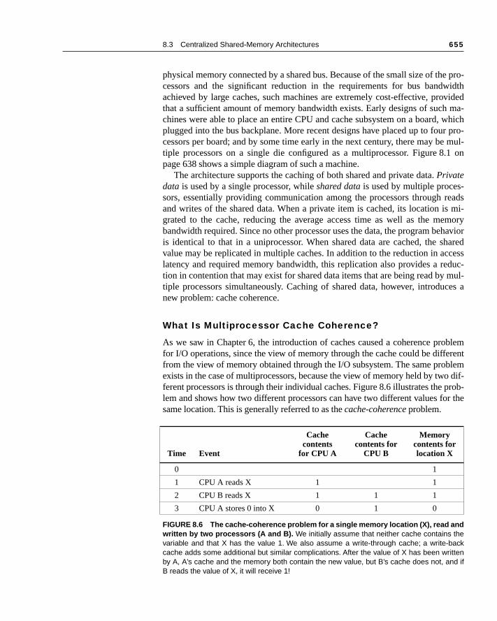
As we saw in Chapter 6, the introduction of caches caused a coherence prfor I/O operations, since the view of memory through the cache could be diffefrom the view of memory obtained through the I/O subsystem. The same proexists in the case of multiprocessors, because the view of memory held by twferent processors is through their individual caches. Figure 8.6 illustrates the lem and shows how two different processors can have two different values fosame location. This is generally referred to as the cache-coherence problem.
Time Event
Cache contents
for CPU A
Cache contents for
CPU B
Memorycontents forlocation X
0 1
1 CPU A reads X 1 1
2 CPU B reads X 1 1 1
3 CPU A stores 0 into X 0 1 0
FIGURE 8.6 The cache-coherence problem for a single memory location (X), read andwritten by two processors (A and B). We initially assume that neither cache contains thevariable and that X has the value 1. We also assume a write-through cache; a write-backcache adds some additional but similar complications. After the value of X has been writtenby A, A’s cache and the memory both contain the new value, but B’s cache does not, and ifB reads the value of X, it will receive 1!
656 Chapter 8 Multiprocessors
of ation,oretemms.ad.
ith read
ssorted
loca-s. Fors can
to behat itusly
ose P2 the therite ofoid are
tion of
quire pro-n an- reade leftst be
Informally, we could say that a memory system is coherent if any read data item returns the most recently written value of that data item. This definiwhile intuitively appealing, is vague and simplistic; the reality is much mcomplex. This simple definition contains two different aspects of memory sysbehavior, both of which are critical to writing correct shared-memory prograThe first aspect, called coherence, defines what values can be returned by a reThe second aspect, called consistency, determines when a written value will bereturned by a read. Let’s look at coherence first.
A memory system is coherent if
1. A read by a processor, P, to a location X that follows a write by P to X, wno writes of X by another processor occurring between the write and theby P, always returns the value written by P.
2. A read by a processor to location X that follows a write by another proceto X returns the written value if the read and write are sufficiently separaand no other writes to X occur between the two accesses.
3. Writes to the same location are serialized: that is, two writes to the sametion by any two processors are seen in the same order by all processorexample, if the values 1 and then 2 are written to a location, processornever read the value of the location as 2 and then later read it as 1.
The first property simply preserves program order—we expect this property true even in uniprocessors. The second property defines the notion of wmeans to have a coherent view of memory: If a processor could continuoread an old data value, we would clearly say that memory was incoherent.
The need for write serialization is more subtle, but equally important. Suppwe did not serialize writes, and processor P1 writes location X followed bywriting location X. Serializing the writes ensures that every processor will seewrite done by P2 at some point. If we did not serialize the writes, it might becase that some processor could see the write of P2 first and then see the wP1, maintaining the value written by P1 indefinitely. The simplest way to avsuch difficulties is to serialize writes, so that all writes to the same locationseen in the same order; this property is called write serialization. Although thethree properties just described are sufficient to ensure coherence, the queswhen a written value will be seen is also important.
To understand why consistency is complex, observe that we cannot rethat a read of X instantaneously see the value written for X by some othercessor. If, for example, a write of X on one processor precedes a read of X oother processor by a very small time, it may be impossible to ensure that thereturns the value of the data written, since the written data may not even havthe processor at that point. The issue of exactly when a written value museen by a reader is defined by a memory consistency model—a topic discussed in
8.3 Centralized Shared-Memory Architectures 657
efinestencyemoryl de-til alles not pro-order. ex-
haserele—aame bothra-nspar-ocatedbeing local readrfor-em byn by
ck-cols,
in4,
icallizedcachevein this
section 8.6. Coherence and consistency are complementary: Coherence dthe behavior of reads and writes to the same memory location, while consisdefines the behavior of reads and writes with respect to accesses to other mlocations. For simplicity, and because we cannot explain the problem in fultail at this point, assume that we require that a write does not complete unprocessors have seen the effect of the write and that the processor dochange the order of any write with any other memory access. This allows thecessor to reorder reads, but forces the processor to finish a write in program We will rely on this assumption until we reach section 8.6, where we will seeactly the meaning of this definition, as well as the alternatives.
Basic Schemes for Enforcing Coherence
The coherence problem for multiprocessors and I/O, while similar in origin,different characteristics that affect the appropriate solution. Unlike I/O, whmultiple data copies are a rare event—one to be avoided whenever possibprogram running on multiple processors will want to have copies of the sdata in several caches. In a coherent multiprocessor, the caches providemigration and replication of shared data items. Coherent caches provide migtion, since a data item can be moved to a local cache and used there in a traent fashion; this reduces the latency to access a shared data item that is allremotely. Coherent caches also provide replication for shared data that is simultaneously read, since the caches make a copy of the data item in thecache. Replication reduces both latency of access and contention for ashared data item. Supporting this migration and replication is critical to pemance in accessing shared data. Thus, rather than trying to solve the problavoiding it in software, small-scale multiprocessors adopt a hardware solutiointroducing a protocol to maintain coherent caches.
The protocols to maintain coherence for multiple processors are called cache-coherence protocols. Key to implementing a cache-coherence protocol is traing the state of any sharing of a data block. There are two classes of protowhich use different techniques to track the sharing status, in use:
■ Directory based—The sharing status of a block of physical memory is keptjust one location, called the directory; we focus on this approach in section 8.when we discuss scalable shared-memory architecture.
■ Snooping—Every cache that has a copy of the data from a block of physmemory also has a copy of the sharing status of the block, and no centrastate is kept. The caches are usually on a shared-memory bus, and all controllers monitor or snoop on the bus to determine whether or not they haa copy of a block that is requested on the bus. We focus on this approach section.
658 Chapter 8 Multiprocessors
ssorsn use a
us of
previ-ess to a
ostcess
writes en- Sincer mustissesquireessor theecider thehich
seri-ping
Snooping protocols became popular with multiprocessors using microproceand caches attached to a single shared memory because these protocols capreexisting physical connection—the bus to memory—to interrogate the statthe caches.
Alternative Protocols
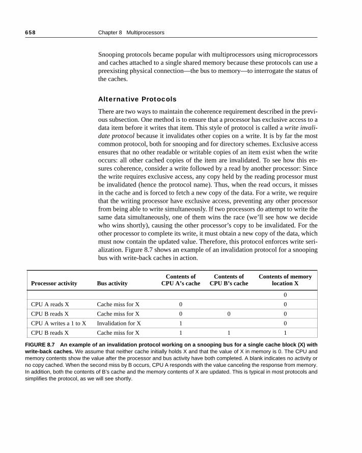
There are two ways to maintain the coherence requirement described in the ous subsection. One method is to ensure that a processor has exclusive accdata item before it writes that item. This style of protocol is called a write invali-date protocol because it invalidates other copies on a write. It is by far the mcommon protocol, both for snooping and for directory schemes. Exclusive acensures that no other readable or writable copies of an item exist when theoccurs: all other cached copies of the item are invalidated. To see how thisures coherence, consider a write followed by a read by another processor:the write requires exclusive access, any copy held by the reading processobe invalidated (hence the protocol name). Thus, when the read occurs, it min the cache and is forced to fetch a new copy of the data. For a write, we rethat the writing processor have exclusive access, preventing any other procfrom being able to write simultaneously. If two processors do attempt to writesame data simultaneously, one of them wins the race (we’ll see how we dwho wins shortly), causing the other processor’s copy to be invalidated. Foother processor to complete its write, it must obtain a new copy of the data, wmust now contain the updated value. Therefore, this protocol enforces writealization. Figure 8.7 shows an example of an invalidation protocol for a snoobus with write-back caches in action.
Processor activity Bus activityContents of
CPU A’s cacheContents of
CPU B’s cacheContents of memory
location X
0
CPU A reads X Cache miss for X 0 0
CPU B reads X Cache miss for X 0 0 0
CPU A writes a 1 to X Invalidation for X 1 0
CPU B reads X Cache miss for X 1 1 1
FIGURE 8.7 An example of an invalidation protocol working on a snooping bus for a single cache block (X) withwrite-back caches. We assume that neither cache initially holds X and that the value of X in memory is 0. The CPU andmemory contents show the value after the processor and bus activity have both completed. A blank indicates no activity orno copy cached. When the second miss by B occurs, CPU A responds with the value canceling the response from memory.In addition, both the contents of B’s cache and the memory contents of X are updated. This is typical in most protocols andsimplifies the protocol, as we will see shortly.
8.3 Centralized Shared-Memory Architectures 659
of a
coled—dcastproto-lidate why,
roto-
iplen a
es ad inval-ork
y tors in
ittene the
at theation
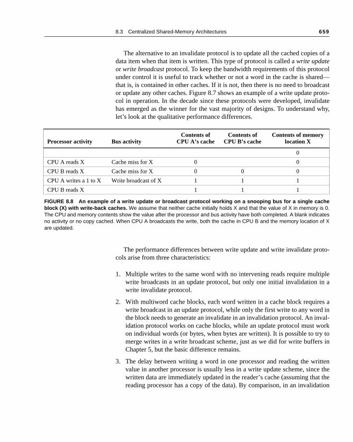
The alternative to an invalidate protocol is to update all the cached copiesdata item when that item is written. This type of protocol is called a write updateor write broadcast protocol. To keep the bandwidth requirements of this protounder control it is useful to track whether or not a word in the cache is sharthat is, is contained in other caches. If it is not, then there is no need to broaor update any other caches. Figure 8.7 shows an example of a write update col in operation. In the decade since these protocols were developed, invahas emerged as the winner for the vast majority of designs. To understandlet’s look at the qualitative performance differences.
The performance differences between write update and write invalidate pcols arise from three characteristics:
1. Multiple writes to the same word with no intervening reads require multwrite broadcasts in an update protocol, but only one initial invalidation iwrite invalidate protocol.
2. With multiword cache blocks, each word written in a cache block requirwrite broadcast in an update protocol, while only the first write to any worthe block needs to generate an invalidate in an invalidation protocol. An inidation protocol works on cache blocks, while an update protocol must won individual words (or bytes, when bytes are written). It is possible to trmerge writes in a write broadcast scheme, just as we did for write buffeChapter 5, but the basic difference remains.
3. The delay between writing a word in one processor and reading the wrvalue in another processor is usually less in a write update scheme, sincwritten data are immediately updated in the reader’s cache (assuming threading processor has a copy of the data). By comparison, in an invalid
Processor activity Bus activityContents of
CPU A’s cacheContents of
CPU B’s cacheContents of memory
location X
0
CPU A reads X Cache miss for X 0 0
CPU B reads X Cache miss for X 0 0 0
CPU A writes a 1 to X Write broadcast of X 1 1 1
CPU B reads X 1 1 1
FIGURE 8.8 An example of a write update or broadcast protocol working on a snooping bus for a single cacheblock (X) with write-back caches. We assume that neither cache initially holds X and that the value of X in memory is 0.The CPU and memory contents show the value after the processor and bus activity have both completed. A blank indicatesno activity or no copy cached. When CPU A broadcasts the write, both the cache in CPU B and the memory location of Xare updated.

660 Chapter 8 Multiprocessors
talled
de-ol ofs fordate,untsds ofcessorct up-ly on
the sim-he bus. pro-
corre-ed byete toe firstinvali-e is. ing. In ae all
e of acom-
data ratherhemedress
ested caus- lowerulti-n im-
protocol, the reader is invalidated first, then later reads the data and is suntil a copy can be read and returned to the processor.
Because bus and memory bandwidth is usually the commodity most inmand in a bus-based multiprocessor, invalidation has become the protocchoice for almost all implementations. Update protocols also cause problemmemory consistency models, reducing the potential performance gains of upmentioned in point 3, even further. In designs with very small processor co(2–4) where the processors are tightly coupled, the larger bandwidth demanupdate may be acceptable. Nonetheless, given the trends in increasing properformance and the related increase in bandwidth demands, we can expedate schemes to be used very infrequently. For this reason, we will focus oninvalidate protocols for the rest of the chapter.
Basic Implementation Techniques
The key to implementing an invalidate protocol in a small-scale machine isuse of the bus to perform invalidates. To perform an invalidate the processorply acquires bus access and broadcasts the address to be invalidated on tAll processors continuously snoop on the bus watching the addresses. Thecessors check whether the address on the bus is in their cache. If so, thesponding data in the cache is invalidated. The serialization of access enforcthe bus also forces serialization of writes, since when two processors compwrite to the same location, one must obtain bus access before the other. Thprocessor to obtain bus access will cause the other processor’s copy to be dated, causing writes to be strictly serialized. One implication of this schemthat a write to a shared data item cannot complete until it obtains bus access
In addition to invalidating outstanding copies of a cache block that is bewritten into, we also need to locate a data item when a cache miss occurswrite-through cache, it is easy to find the recent value of a data item, sincwritten data are always sent to the memory, from which the most recent valudata item can always be fetched. (Write buffers can lead to some additional plexities, which are discussed in section 8.6.)
For a write-back cache, however, the problem of finding the most recentvalue is harder, since the most recent value of a data item can be in a cachethan in memory. Happily, write-back caches can use the same snooping scboth for caches misses and for writes: Each processor snoops every adplaced on the bus. If a processor finds that it has a dirty copy of the requcache block, it provides that cache block in response to the read request andes the memory access to be aborted. Since write-back caches generaterequirements for memory bandwidth, they are greatly preferable in a mprocessor, despite the slight increase in complexity. Therefore, we focus oplementation with write-back caches.
8.3 Centralized Shared-Memory Architectures 661
. Fur-ent.t, are
ritesse, ifus in awrite
te bitit. Byer a
te oc-as pri-The
ngeds thishe alsoted by
ntiallyy one way.ed ind up-eeds or to
a copyhen ity in thealing
en-tivity
vity is, thenrieveipro-e indi-mes itrther
The normal cache tags can be used to implement the process of snoopingthermore, the valid bit for each block makes invalidation easy to implemRead misses, whether generated by an invalidation or by some other evenalso straightforward since they simply rely on the snooping capability. For wwe’d like to know whether any other copies of the block are cached, becauthere are no other cached copies, then the write need not be placed on the bwrite-back cache. Not sending the write reduces both the time taken by the and the required bandwidth.
To track whether or not a cache block is shared we can add an extra staassociated with each cache block, just as we have a valid bit and a dirty badding a bit indicating whether the block is shared, we can decide whethwrite must generate an invalidate. When a write to a block in the shared stacurs, the cache generates an invalidation on the bus and marks the block vate. No further invalidations will be sent by that processor for that block. processor with the sole copy of a cache block is normally called the owner of thecache block.
When an invalidation is sent, the state of the owner’s cache block is chafrom shared to unshared (or exclusive). If another processor later requestcache block, the state must be made shared again. Since our snooping cacsees any misses, it knows when the exclusive cache block has been requesanother processor and the state should be made shared.
Since every bus transaction checks cache-address tags, this could poteinterfere with CPU cache accesses. This potential interference is reduced bof two techniques: duplicating the tags or employing a multilevel cache within-clusion, whereby the levels closer to the CPU are a subset of those further aIf the tags are duplicated, then the CPU and the snooping activity may proceparallel. Of Of course, on a cache miss the processor needs to arbitrate for andate both sets of tags. Likewise, if the snoop finds a matching tag entry, it nto arbitrate for and access both sets of cache tags (to perform an invalidateupdate the shared bit), as well as possibly the cache data array to retrieve of a block. Thus with duplicate tags the processor only needs to be stalled wdoes a cache access at the same time that a snoop has detected a copcache. Furthermore, snooping activity is delayed only when the cache is dewith a miss.
If the CPU uses a multilevel cache with the inclusion property, then everytry in the primary cache is also in the secondary cache. Thus the snoop accan be directed to the second-level cache, while most of the processor’s actidirected to the primary cache. If the snoop gets a hit in the secondary cacheit must arbitrate for the primary cache to update the state and possibly retthe data, which usually requires a stall of the processor. Since many multcessors use a multilevel cache to decrease the bandwidth demands of thvidual processors, this solution has been adopted in many designs. Sometimay even be useful to duplicate the tags of the secondary cache to fu
662 Chapter 8 Multiprocessors
ss the
pend- cacheip istocols
finite pro-well asuests
decrease contention between the CPU and the snooping activity. We discuinclusion property in more detail in section 8.8.
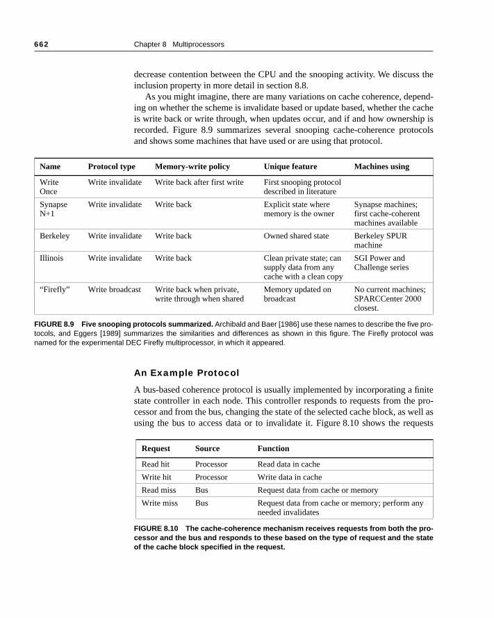
As you might imagine, there are many variations on cache coherence, deing on whether the scheme is invalidate based or update based, whether theis write back or write through, when updates occur, and if and how ownershrecorded. Figure 8.9 summarizes several snooping cache-coherence proand shows some machines that have used or are using that protocol.
An Example Protocol
A bus-based coherence protocol is usually implemented by incorporating a state controller in each node. This controller responds to requests from thecessor and from the bus, changing the state of the selected cache block, as using the bus to access data or to invalidate it. Figure 8.10 shows the req
Name Protocol type Memory-write policy Unique feature Machines using
Write Once
Write invalidate Write back after first write First snooping protocol described in literature
Synapse N+1
Write invalidate Write back Explicit state where memory is the owner
Synapse machines; first cache-coherent machines available
Berkeley Write invalidate Write back Owned shared state Berkeley SPUR machine
Illinois Write invalidate Write back Clean private state; can supply data from any cache with a clean copy
SGI Power and Challenge series
“Firefly” Write broadcast Write back when private,write through when shared
Memory updated on broadcast
No current machines; SPARCCenter 2000 closest.
FIGURE 8.9 Five snooping protocols summarized. Archibald and Baer [1986] use these names to describe the five pro-tocols, and Eggers [1989] summarizes the similarities and differences as shown in this figure. The Firefly protocol wasnamed for the experimental DEC Firefly multiprocessor, in which it appeared.
Request Source Function
Read hit Processor Read data in cache
Write hit Processor Write data in cache
Read miss Bus Request data from cache or memory
Write miss Bus Request data from cache or memory; perform anyneeded invalidates
FIGURE 8.10 The cache-coherence mechanism receives requests from both the pro-cessor and the bus and responds to these based on the type of request and the stateof the cache block specified in the request.
8.3 Centralized Shared-Memory Architectures 663
g fromen ach anessorsk iswriteansac-
k us-reeU re- right).itions
state of
ssordirty8.11 in amiss stated only. ingstatehalf
ck isly oneor tog alllock
block blocka sub-.12, com-
, andys upetail
generated by the processor-cache module in a node as well as those cominthe bus. For simplicity, the protocol we explain does not distinguish betwewrite hit and a write miss to a shared cache block: in both cases, we treat suaccess as a write miss. When the write miss is placed on the bus, any procwith copies of the cache block invalidate it. In a write-back cache, if the blocexclusive in just one cache, that cache also writes back the block. Treating hits to shared blocks as cache misses reduces the number of different bus trtions and simplifies the controller.
Figure 8.11 shows a finite-state transition diagram for a single cache blocing a write-invalidation protocol and a write-back cache. For simplicity, the thstates of the protocol are duplicated to represent transitions based on CPquests (on the left), as opposed to transitions based on bus requests (on theBoldface type is used to distinguish the bus actions, as opposed to the condon which a state transition depends. The state in each node represents the the selected cache block specified by the processor or bus request.
All of the states in this cache protocol would be needed in a uniprocecache, where they would correspond to the invalid, valid (and clean), and states. All of the state changes indicated by arcs in the left half of Figure would be needed in a write-back uniprocessor cache; the only differencemultiprocessor with coherence is that the controller must generate a write when the controller has a write hit for a cache block in the shared state. Thechanges represented by the arcs in the right half of Figure 8.11 are needefor coherence and would not appear at all in a uniprocessor cache controller
In reality, there is only one finite-state machine per cache, with stimuli comeither from the attached CPU or from the bus. Figure 8.12 shows how the transitions in the right half of Figure 8.11 are combined with those in the left of the figure to form a single state diagram for each cache block.
To understand why this protocol works, observe that any valid cache bloeither in the shared state in multiple caches or in the exclusive state in exactcache. Any transition to the exclusive state (which is required for a processwrite to the block) requires a write miss to be placed on the bus, causincaches to make the block invalid. In addition, if some other cache had the bin exclusive state, that cache generates a write back, which supplies the containing the desired address. Finally, if a read miss occurs on the bus to ain the exclusive state, the owning cache also makes its state shared, forcing sequent write to require exclusive ownership. The actions in gray in Figure 8which handle read and write misses on the bus, are essentially the snoopingponent of the protocol. One other property that is preserved in this protocolin most other protocols, is that any memory block in the shared state is alwato date in the memory. This simplifies the implementation, as we will see in din section 8.5.
664 Chapter 8 Multiprocessors
ica-se is
pro-s, and
rly, ifisses
Although our simple cache protocol is correct, it omits a number of compltions that make the implementation much trickier. The most important of thethat the protocol assumes that operations are atomic—that is, an operation can bedone in such a way that no intervening operation can occur. For example, thetocol described assumes that write misses can be detected, acquire the bureceive a response as a single atomic action. In reality this is not true. Similawe used a split transaction bus (see Chapter 6, section 6.3), then read mwould also not be atomic.
FIGURE 8.11 A write-invalidate, cache-coherence protocol for a write-back cache showing the states and statetransitions for each block in the cache. The cache states are shown in circles with any access permitted by the CPU with-out a state transition shown in parenthesis under the name of the state. The stimulus causing a state change is shown onthe transition arcs in regular type, and any bus actions generated as part of the state transition are shown on the transitionarc in bold. The stimulus actions apply to a block in the cache, not to a specific address in the cache. Hence, a read miss toa line in the shared state is a miss for that cache block but for a different address. The left side of the diagram shows statetransitions based on actions of the CPU associated with this cache; the right side shows transitions based on operations onthe bus. A read miss in the exclusive or shared state and a write miss in the exclusive state occur when the address request-ed by the CPU does not match the address in the cache block. Such a miss is a standard cache replacement miss. An at-tempt to write a block in the shared state always generates a miss, even if the block is present in the cache, since the blockmust be made exclusive. Whenever a bus transaction occurs, all caches that contain the cache block specified in the bustransaction take the action dictated by the right half of the diagram. The protocol assumes that memory provides data on aread miss for a block that is clean in all caches. In actual implementations, these two sets of state diagrams are combined.This protocol is somewhat simpler than those in use in existing multiprocessors.
Invalid
Exclusive(read/write)
Write miss forthis block
Write missfor this block
CPU write hitCPU read hit
Cache state transitions basedon requests from the bus
CPU write
Pla
ce w
rite
mis
s o
n b
us
CPU read
miss
Writ
e-bac
k blo
ck
Place
writ
e m
iss
on bus
Place r
ead m
iss o
n bus CPU w
rite
Place read miss on bus
Place readmiss on bus
Wri
te-b
ack
blo
ck;
abo
rt m
emo
ryac
cess
Writ
e-bac
k blo
ck; a
bort
mem
ory ac
cess
CPU read
Cache state transitionsbased on requests from CPU
Shared(read only)
Exclusive(read/write)
CPU read hit
CPU write miss
Write-back cache blockPlace write miss on bus
CPUreadmiss
Read missfor this block
InvalidShared
(read only)
8.3 Centralized Shared-Memory Architectures 665
with with
ed inons the re-lifiesritethe
Nonatomic actions introduce the possibility that the protocol can deadlock,meaning that it reaches a state where it cannot continue. Appendix E dealsthese complex issues, showing how the protocol can be modified to dealnonatomic writes without introducing deadlock.
As stated earlier, this coherence protocol is actually simpler than those uspractice. There are two major simplifications. First, in this protocol all transitito the exclusive state generate a write miss on the bus, and we assume thatquesting cache always fills the block with the contents returned. This simpthe detailed implementation. Most real protocols distinguish between a wmiss and a write hit, which can occur when the cache block is initially in shared state. Such misses are called ownership or upgrade misses, since they
FIGURE 8.12 Cache-coherence state diagram with the state transitions induced bythe local processor shown in black and by the bus activities shown in gray. As inFigure 8.11, the activities on a transition are shown in bold.
Exclusive(read/write)
CPU write hitCPU read hit
Write missfor block
CPU write
Pla
ce w
rite
mis
s o
n b
us
Read
miss
for b
lock
CPU read
miss
Writ
e-bac
k blo
ck
Place w
rite m
iss o
n bus
CPU writ
e
Place read miss on bus
Place readmiss on bus
CPU read
CPU read hit
CPU write miss
Write-back dataPlace write miss on bus
CPUreadmiss
Invalid
Write miss for this block
Writ
e-bac
k dat
a; p
lace r
ead m
iss o
n bus
Shared(read only)
Wri
te-b
ack
blo
ck
666 Chapter 8 Multiprocessors
etch.
n of
en axactly gen- widext partl and
rentacherafficsub-ck sizeg to
rallel
t to
block
t, andt is thee as a
exclu-l that
reasesize
involve changing the state of the block, but do not actually require a data fTo support such state changes, the protocol uses an invalidate operation, in addi-tion to a write miss. With such operations, however, the actual implementatiothe protocol becomes slightly more complex.
The second major simplification is that many machines distinguish betwecache block that is really shared and one that exists in the clean state in eone cache. This addition of a “clean and private” state eliminates the need toerate a bus transaction on a write to such a block. Another enhancement inuse allows other caches to supply data on a miss to a shared block. The neof this section examines the performance of these protocols for our parallemultiprogrammed workloads.
Performance of Snooping Coherence Protocols
In a bus-based multiprocessor using an invalidation protocol, several diffephenomena combine to determine performance. In particular, the overall cperformance is a combination of the behavior of uniprocessor cache miss tand the traffic caused by communication, which results in invalidations and sequent cache misses. Changing the processor count, cache size, and blocan affect these two components of the miss rate in different ways, leadinoverall system behavior that is a combination of the two effects.
Performance for the Parallel Program WorkloadIn this section, we use a simulator to study the performance of our four paprograms. For these measurements, the problem sizes are as follows:
■ Barnes-Hut—16K bodies run for six time steps (the accuracy control is se1.0, a typical, realistic value);
■ FFT—1 million complex data points
■ LU—A 512 × 512 matrix is used with 16 × 16 blocks
■ Ocean—A 130 × 130 grid with a typical error tolerance
In looking at the miss rates as we vary processor count, cache size, andsize, we decompose the total miss rate into coherence misses and normal unipro-cessor misses. The normal uniprocessor misses consist of capacity, confliccompulsory misses. We label these misses as capacity misses, because thadominant cause for these benchmarks. For these measurements, we includcoherence miss any write misses needed to upgrade a block from shared tosive, even though no one is sharing the cache block. This reflects a protocodoes not distinguish between a private and shared cache block.
Figure 8.13 shows the data miss rates for our four applications, as we incthe number of processors from one to 16, while keeping the problem
8.3 Centralized Shared-Memory Architectures 667
he in-ng then turndiffers
t the con-ome
ache pro-
ssesnt oft ef-dualoces-
ltiple and
nflictsltiple
s little caus-
it re-nge indue toad to act—aste. In-at areis in-even-s in rate. thate buts thatir of
nt inccurse lat-,fasterure be-
constant. As we increase the number of processors, the total amount of caccreases, usually causing the capacity misses to drop. In contrast, increasiprocessor count usually causes the amount of communication to increase, icausing the coherence misses to rise. The magnitude of these two effects by application.
In FFT, the capacity miss rate drops (from nearly 7% to just over 5%) bucoherence miss rate increases (from about 1% to about 2.7%), leading to astant overall miss rate. Ocean shows a combination of effects, including sthat relate to the partitioning of the grid and how grid boundaries map to cblocks. For a typical 2D grid code the communication-generated misses areportional to the boundary of each partition of the grid, while the capacity miare proportional to the area of the grid. Therefore, increasing the total amoucache while keeping the total problem size fixed will have a more significanfect on the capacity miss rate, at least until each subgrid fits within an indiviprocessor’s cache. The significant jump in miss rate between one and two prsors occurs because of conflicts that arise from the way in which the mugrids are mapped to the caches. This conflict is present for direct-mappedtwo-way set associative caches, but fades at higher associativities. Such coare not unusual in array-based applications, especially when there are mugrids in use at once. In Barnes and LU the increase in processor count haeffect on the miss rate, sometimes causing a slight increase and sometimesing a slight decrease.
Increasing the cache size has a beneficial effect on performance, sinceduces the frequency of costly cache misses. Figure 8.14 illustrates the chamiss rate as cache size is increased, showing the portion of the miss rate coherence misses and to uniprocessor capacity misses. Two effects can lemiss rate that does not decrease—at least not as quickly as we might expecache size increases: inherent communication and plateaus in the miss raherent communication leads to a certain frequency of coherence misses thnot significantly affected by increasing cache size. Thus if the cache size creased while maintaining a fixed problem size, the coherence miss rate tually limits the decrease in cache miss rate. This effect is most obviouBarnes, where the coherence miss rate essentially becomes the entire miss
A less important effect is a temporary plateau in the capacity miss ratearises when the application has some fraction of its data present in cachsome significant portion of the data set does not fit in the cache or in cacheare slightly bigger. In LU, a very small cache (about 4 KB) can capture the pa16 × 16 blocks used in the inner loop; beyond that the next big improvemecapacity miss rate occurs when both matrices fit in the caches, which owhen the total cache size is between 4 MB and 8 MB, a data point we will seer. This working set effect is partly at work between 32 KB and 128 KB for FFTwhere the capacity miss rate drops only 0.3%. Beyond that cache size, a decrease in the capacity miss rate is seen, as some other major data struct
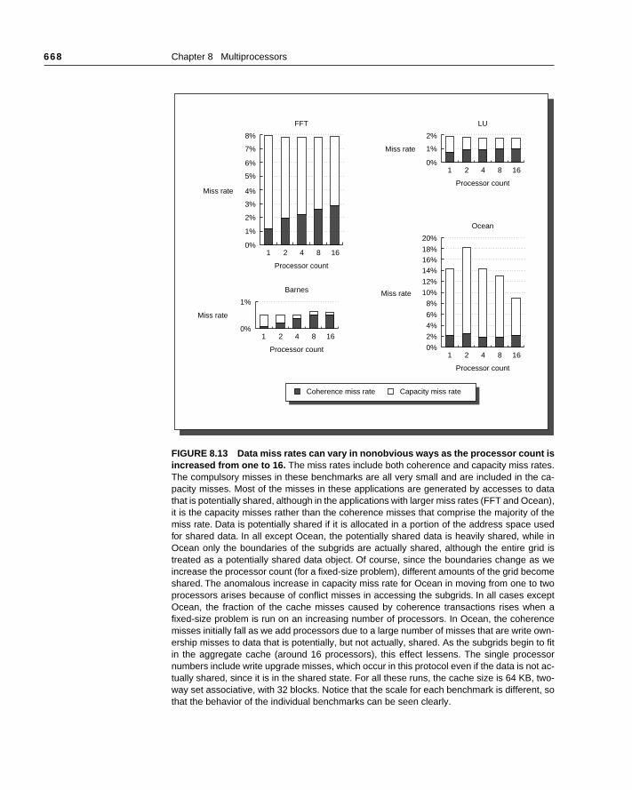
668 Chapter 8 Multiprocessors
FIGURE 8.13 Data miss rates can vary in nonobvious ways as the processor count isincreased from one to 16. The miss rates include both coherence and capacity miss rates.The compulsory misses in these benchmarks are all very small and are included in the ca-pacity misses. Most of the misses in these applications are generated by accesses to datathat is potentially shared, although in the applications with larger miss rates (FFT and Ocean),it is the capacity misses rather than the coherence misses that comprise the majority of themiss rate. Data is potentially shared if it is allocated in a portion of the address space usedfor shared data. In all except Ocean, the potentially shared data is heavily shared, while inOcean only the boundaries of the subgrids are actually shared, although the entire grid istreated as a potentially shared data object. Of course, since the boundaries change as weincrease the processor count (for a fixed-size problem), different amounts of the grid becomeshared. The anomalous increase in capacity miss rate for Ocean in moving from one to twoprocessors arises because of conflict misses in accessing the subgrids. In all cases exceptOcean, the fraction of the cache misses caused by coherence transactions rises when afixed-size problem is run on an increasing number of processors. In Ocean, the coherencemisses initially fall as we add processors due to a large number of misses that are write own-ership misses to data that is potentially, but not actually, shared. As the subgrids begin to fitin the aggregate cache (around 16 processors), this effect lessens. The single processornumbers include write upgrade misses, which occur in this protocol even if the data is not ac-tually shared, since it is in the shared state. For all these runs, the cache size is 64 KB, two-way set associative, with 32 blocks. Notice that the scale for each benchmark is different, sothat the behavior of the individual benchmarks can be seen clearly.
Miss rate
0%
3%
2%
1%
1 2 4
Processor count
FFT
8 16
8%
4%
7%
6%
5%
Miss rate
0%
6%
4%
2%
1 2 4
Processor count
Ocean
8 16
16%18%
20%
8%
14%
12%
10%
Miss rate
0%
1%
1 2 4
Processor count
LU
8 16
2%
Miss rate
0%1 2 4
Processor count
Barnes
8 16
1%
Coherence miss rate Capacity miss rate
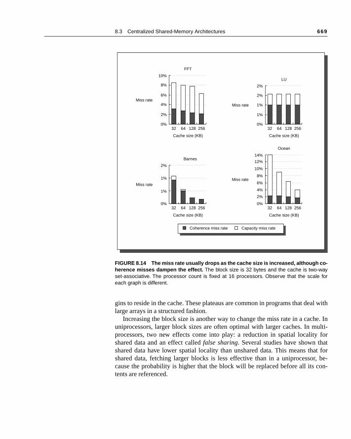
8.3 Centralized Shared-Memory Architectures 669
al with
he. Inulti- fortat forr, be-con-
gins to reside in the cache. These plateaus are common in programs that delarge arrays in a structured fashion.
Increasing the block size is another way to change the miss rate in a cacuniprocessors, larger block sizes are often optimal with larger caches. In mprocessors, two new effects come into play: a reduction in spatial localityshared data and an effect called false sharing. Several studies have shown thashared data have lower spatial locality than unshared data. This means thshared data, fetching larger blocks is less effective than in a uniprocessocause the probability is higher that the block will be replaced before all its tents are referenced.
FIGURE 8.14 The miss rate usually drops as the cache size is increased, although co-herence misses dampen the effect. The block size is 32 bytes and the cache is two-wayset-associative. The processor count is fixed at 16 processors. Observe that the scale foreach graph is different.
Miss rate
0%
4%
2%
32 64 128
Cache size (KB)
FFT
256
10%
6%
8%
Miss rate
0%
1%
1%
32 64 128
Cache size (KB)
LU
256
2%
2%
Miss rate
0%
6%
2%
4%
32 64 128
Cache size (KB)
Ocean
256
14%
10%
8%
12%
Miss rate
0%
1%
32 64 128
Cache size (KB)
Barnes
256
2%
1%
Coherence miss rate Capacity miss rate
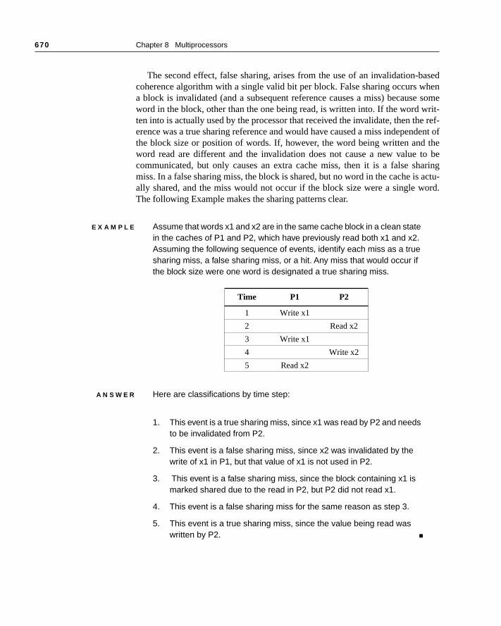
670 Chapter 8 Multiprocessors
asedhen
e somerit-e ref-dent of theto bearing
actu-ord.
The second effect, false sharing, arises from the use of an invalidation-bcoherence algorithm with a single valid bit per block. False sharing occurs wa block is invalidated (and a subsequent reference causes a miss) becausword in the block, other than the one being read, is written into. If the word wten into is actually used by the processor that received the invalidate, then therence was a true sharing reference and would have caused a miss indepenthe block size or position of words. If, however, the word being written andword read are different and the invalidation does not cause a new value communicated, but only causes an extra cache miss, then it is a false shmiss. In a false sharing miss, the block is shared, but no word in the cache isally shared, and the miss would not occur if the block size were a single wThe following Example makes the sharing patterns clear.
E X A M P L E Assume that words x1 and x2 are in the same cache block in a clean state in the caches of P1 and P2, which have previously read both x1 and x2. Assuming the following sequence of events, identify each miss as a true sharing miss, a false sharing miss, or a hit. Any miss that would occur if the block size were one word is designated a true sharing miss.
A N S W E R Here are classifications by time step:
1. This event is a true sharing miss, since x1 was read by P2 and needs to be invalidated from P2.
2. This event is a false sharing miss, since x2 was invalidated by the write of x1 in P1, but that value of x1 is not used in P2.
3. This event is a false sharing miss, since the block containing x1 is marked shared due to the read in P2, but P2 did not read x1.
4. This event is a false sharing miss for the same reason as step 3.
5. This event is a true sharing miss, since the value being read was written by P2. ■
Time P1 P2
1 Write x1
2 Read x2
3 Write x1
4 Write x2
5 Read x2

8.3 Centralized Shared-Memory Architectures 671
r a 16-rnes, num-In thete. In
pacitysed ation in ex- more
Figure 8.15 shows the miss rates as the cache block size is increased foprocessor run with a 64-KB cache. The most interesting behavior is in Bawhere the miss rate initially declines and then rises due to an increase in theber of coherence misses, which probably occurs because of false sharing. other benchmarks, increasing the block size decreases the overall miss raOcean and LU, the block size increase affects both the coherence and camiss rates about equally. In FFT, the coherence miss rate is actually decreaa faster rate than the capacity miss rate. This is because the communicatFFT is structured to be very efficient. In less optimized programs, we wouldpect more false sharing and less spatial locality for shared data, resulting inbehavior like that of Barnes.
FIGURE 8.15 The data miss rate drops as the cache block size is increased. All theseresults are for a 16-processor run with a 64-KB cache and two-way set associativity. Onceagain we use different scales for each benchmark.
Miss rate
0%
6%
4%
2%
16 32 64
Block size (bytes)
FFT
128
14%
10%
8%
12%
Miss rate
0%
2%
1%
16 32 64
Block size (bytes)
LU
128
4%
3%
Miss rate
0%
6%
2%
4%
16 32 64
Block size (bytes)
Ocean
128
14%
10%
8%
12%
Miss rate
0%16 32 64
Block size (bytes)
Barnes
128
1%
Coherence miss rate Capacity miss rate
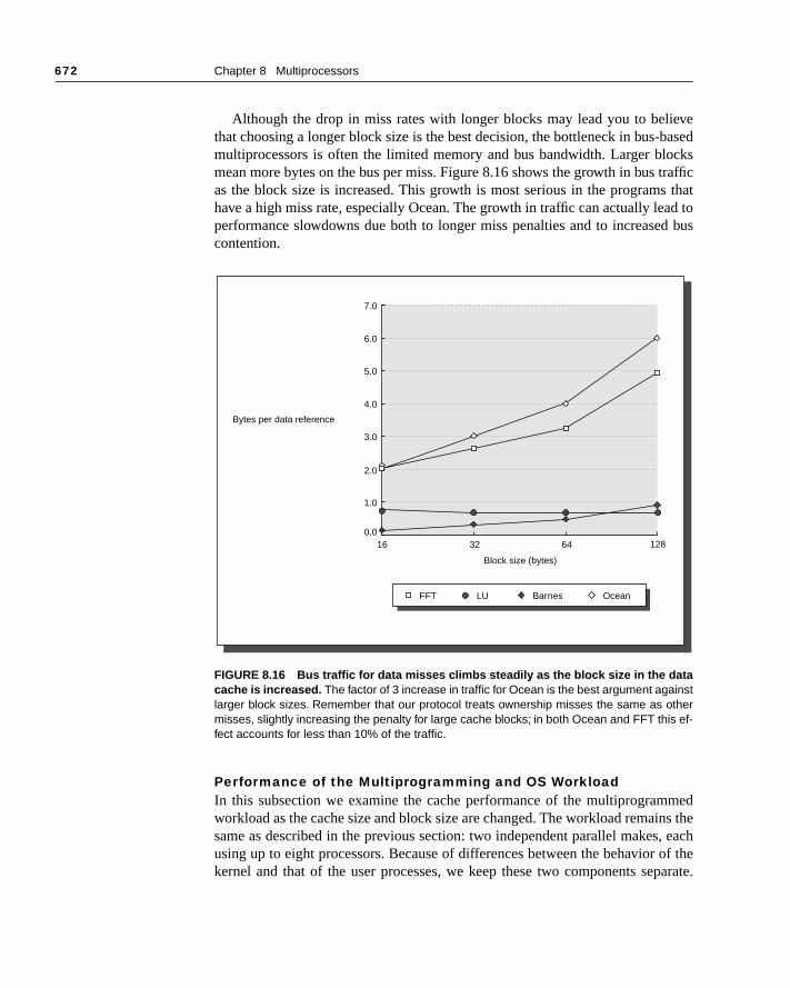
672 Chapter 8 Multiprocessors
ievebasedcks
traffics thatad tod bus
medins the, each of theparate.
Although the drop in miss rates with longer blocks may lead you to belthat choosing a longer block size is the best decision, the bottleneck in bus-multiprocessors is often the limited memory and bus bandwidth. Larger blomean more bytes on the bus per miss. Figure 8.16 shows the growth in bus as the block size is increased. This growth is most serious in the programhave a high miss rate, especially Ocean. The growth in traffic can actually leperformance slowdowns due both to longer miss penalties and to increasecontention.
Performance of the Multiprogramming and OS WorkloadIn this subsection we examine the cache performance of the multiprogramworkload as the cache size and block size are changed. The workload remasame as described in the previous section: two independent parallel makesusing up to eight processors. Because of differences between the behaviorkernel and that of the user processes, we keep these two components se
FIGURE 8.16 Bus traffic for data misses climbs steadily as the block size in the datacache is increased. The factor of 3 increase in traffic for Ocean is the best argument againstlarger block sizes. Remember that our protocol treats ownership misses the same as othermisses, slightly increasing the penalty for large cache blocks; in both Ocean and FFT this ef-fect accounts for less than 10% of the traffic.
7.0
4.0
5.0
6.0
3.0
2.0
1.0
Bytes per data reference
0.0
Block size (bytes)
16 32 64 128
FFT LU Barnes Ocean
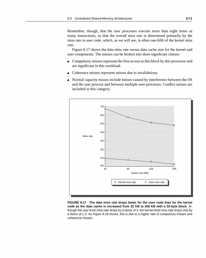
8.3 Centralized Shared-Memory Architectures 673
es as themiss
el and
or and
he OSes are
Remember, though, that the user processes execute more than eight timmany instructions, so that the overall miss rate is determined primarily bymiss rate in user code, which, as we will see, is often one-fifth of the kernel rate.
Figure 8.17 shows the data miss rate versus data cache size for the kernuser components. The misses can be broken into three significant classes:
■ Compulsory misses represent the first access to this block by this processare significant in this workload.
■ Coherence misses represent misses due to invalidations.
■ Normal capacity misses include misses caused by interference between tand the user process and between multiple user processes. Conflict missincluded in this category.
FIGURE 8.17 The data miss rate drops faster for the user code than for the kernelcode as the data cache is increased from 32 KB to 256 KB with a 32-byte block. Al-though the user level miss rate drops by a factor of 3, the kernel level miss rate drops only bya factor of 1.3. As Figure 8.18 shows, this is due to a higher rate of compulsory misses andcoherence misses.
7%
4%
5%
6%
3%
2%
1%
Miss rate
0%
Cache size (KB)
32 64 128 256
Kernel miss rate User miss rate
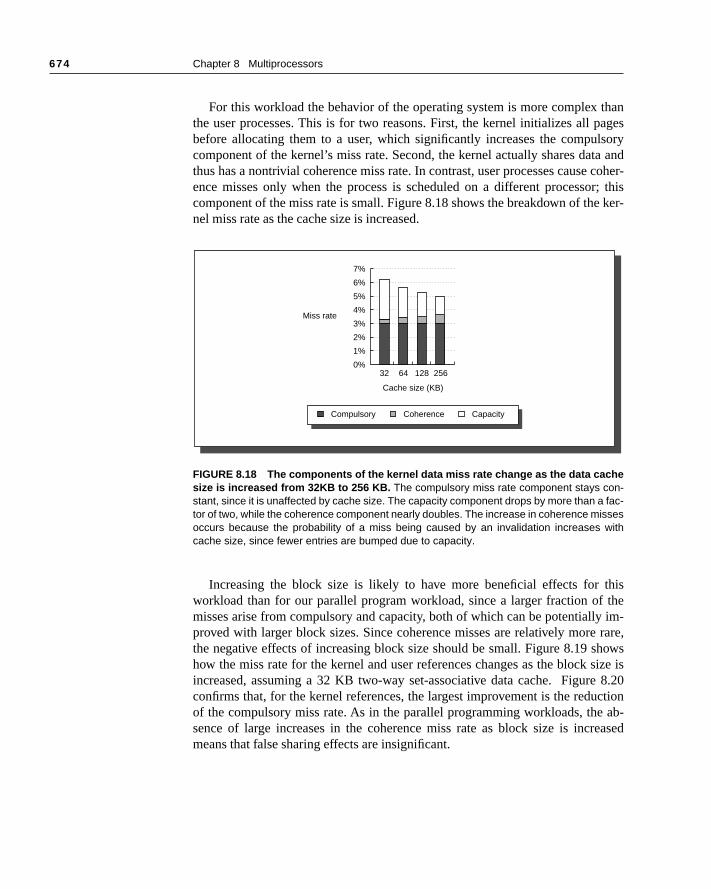
674 Chapter 8 Multiprocessors
thanages
lsoryta and coher-r; this ker-
this the im- rare,howssize is 8.20ction ab-reased
For this workload the behavior of the operating system is more complex the user processes. This is for two reasons. First, the kernel initializes all pbefore allocating them to a user, which significantly increases the compucomponent of the kernel’s miss rate. Second, the kernel actually shares dathus has a nontrivial coherence miss rate. In contrast, user processes causeence misses only when the process is scheduled on a different processocomponent of the miss rate is small. Figure 8.18 shows the breakdown of thenel miss rate as the cache size is increased.
Increasing the block size is likely to have more beneficial effects for workload than for our parallel program workload, since a larger fraction ofmisses arise from compulsory and capacity, both of which can be potentiallyproved with larger block sizes. Since coherence misses are relatively morethe negative effects of increasing block size should be small. Figure 8.19 show the miss rate for the kernel and user references changes as the block increased, assuming a 32 KB two-way set-associative data cache. Figureconfirms that, for the kernel references, the largest improvement is the reduof the compulsory miss rate. As in the parallel programming workloads, thesence of large increases in the coherence miss rate as block size is incmeans that false sharing effects are insignificant.
FIGURE 8.18 The components of the kernel data miss rate change as the data cachesize is increased from 32KB to 256 KB. The compulsory miss rate component stays con-stant, since it is unaffected by cache size. The capacity component drops by more than a fac-tor of two, while the coherence component nearly doubles. The increase in coherence missesoccurs because the probability of a miss being caused by an invalidation increases withcache size, since fewer entries are bumped due to capacity.
Miss rate
0%
2%
4%
6%
5%
3%
1%
32 64 128
Cache size (KB)
256
7%
Compulsory Coherence Capacity
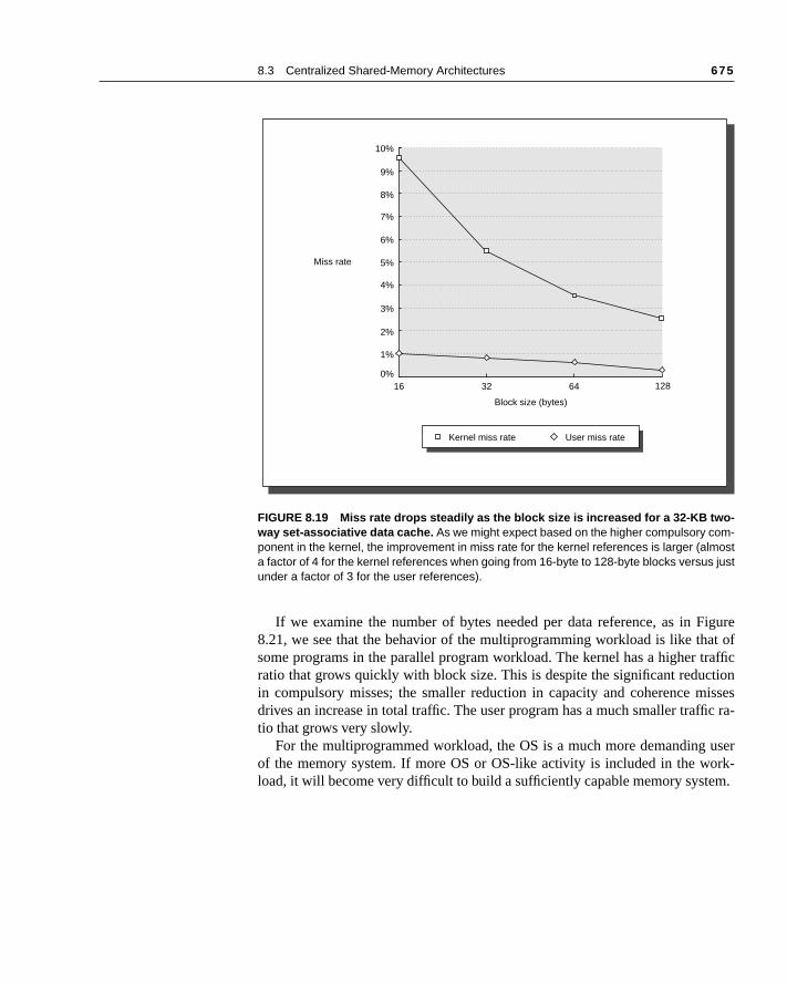
8.3 Centralized Shared-Memory Architectures 675
iguret of
raffictionissesc ra-
userrk-
m.
If we examine the number of bytes needed per data reference, as in F8.21, we see that the behavior of the multiprogramming workload is like thasome programs in the parallel program workload. The kernel has a higher tratio that grows quickly with block size. This is despite the significant reducin compulsory misses; the smaller reduction in capacity and coherence mdrives an increase in total traffic. The user program has a much smaller traffitio that grows very slowly.
For the multiprogrammed workload, the OS is a much more demanding of the memory system. If more OS or OS-like activity is included in the woload, it will become very difficult to build a sufficiently capable memory syste
FIGURE 8.19 Miss rate drops steadily as the block size is increased for a 32-KB two-way set-associative data cache. As we might expect based on the higher compulsory com-ponent in the kernel, the improvement in miss rate for the kernel references is larger (almosta factor of 4 for the kernel references when going from 16-byte to 128-byte blocks versus justunder a factor of 3 for the user references).
10%
6%
7%
8%
9%
4%
5%
3%
1%
2%
Miss rate
0%
Block size (bytes)
16 32 64 128
Kernel miss rate User miss rate
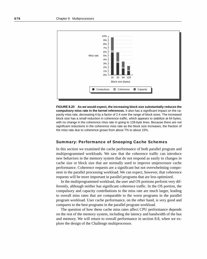
676 Chapter 8 Multiprocessors
andduceges inachempo-rence dif-, thedingralleld and
pendse bus ex-
Summary: Performance of Snooping Cache Schemes
In this section we examined the cache performance of both parallel programmultiprogrammed workloads. We saw that the coherence traffic can intronew behaviors in the memory system that do not respond as easily to chancache size or block size that are normally used to improve uniprocessor cperformance. Coherence requests are a significant but not overwhelming conent in the parallel processing workload. We can expect, however, that coherequests will be more important in parallel programs that are less optimized.
In the multiprogrammed workload, the user and OS portions perform veryferently, although neither has significant coherence traffic. In the OS portioncompulsory and capacity contributions to the miss rate are much larger, leato overall miss rates that are comparable to the worst programs in the paprogram workload. User cache performance, on the other hand, is very goocompares to the best programs in the parallel program workload.
The question of how these cache miss rates affect CPU performance deon the rest of the memory system, including the latency and bandwidth of thand memory. We will return to overall performance in section 8.8, when weplore the design of the Challenge multiprocessor.
FIGURE 8.20 As we would expect, the increasing block size substantially reduces thecompulsory miss rate in the kernel references. It also has a significant impact on the ca-pacity miss rate, decreasing it by a factor of 2.4 over the range of block sizes. The increasedblock size has a small reduction in coherence traffic, which appears to stabilize at 64 bytes,with no change in the coherence miss rate in going to 128-byte lines. Because there are notsignificant reductions in the coherence miss rate as the block size increases, the fraction ofthe miss rate due to coherence grows from about 7% to about 15%.
Miss rate
0%
2%
4%
9%
8%
7%
6%
5%
3%
1%
16 32 64
Block size (bytes)
128
10%
Compulsory Coherence Capacity
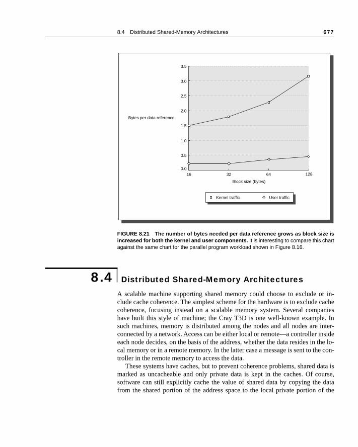
8.4 Distributed Shared-Memory Architectures 677
r in- cachepanies. In inter-nside the lo-e con-
data isourse,dataf the
A scalable machine supporting shared memory could choose to exclude oclude cache coherence. The simplest scheme for the hardware is to excludecoherence, focusing instead on a scalable memory system. Several comhave built this style of machine; the Cray T3D is one well-known examplesuch machines, memory is distributed among the nodes and all nodes areconnected by a network. Access can be either local or remote—a controller ieach node decides, on the basis of the address, whether the data resides incal memory or in a remote memory. In the latter case a message is sent to thtroller in the remote memory to access the data.
These systems have caches, but to prevent coherence problems, sharedmarked as uncacheable and only private data is kept in the caches. Of csoftware can still explicitly cache the value of shared data by copying the from the shared portion of the address space to the local private portion o
FIGURE 8.21 The number of bytes needed per data reference grows as block size isincreased for both the kernel and user components. It is interesting to compare this chartagainst the same chart for the parallel program workload shown in Figure 8.16.
8.4 Distributed Shared-Memory Architectures
3.5
2.0
2.5
3.0
1.5
1.0
0.5
Bytes per data reference
0.0
Block size (bytes)
16 32 64 128
Kernel traffic User traffic
678 Chapter 8 Multiprocessors
. Thed, al-mote. echa-iques
vellicitlyruc-asedthat thatceratelymers
being costt be
refer-ech-n) orer areneed-
sefultched
emoteccessabout
ll-scaleto ex-rtain-ould be
be ad-very cen-ental
ve, as 16
address space that is cached. Coherence is then controlled by softwareadvantage of such a mechanism is that little hardware support is requirethough support for features such as block copy may be useful, since reaccesses fetch only single words (or double words) rather than cache blocks
There are several major disadvantages to this approach. First, compiler mnisms for transparent software cache coherence are very limited. The technthat currently exist apply primarily to programs with well-structured loop-leparallelism, and these techniques have significant overhead arising from expcopying data. For irregular problems or problems involving dynamic data sttures and pointers (including operating systems, for example), compiler-bsoftware cache coherence is currently impractical. The basic difficulty is software-based coherence algorithms must be conservative: every blockmight be shared must be treated as if it is shared. This results in excess coherenoverhead, because the compiler cannot predict the actual sharing accuenough. Due to the complexity of the possible interactions, asking programto deal with coherence is unworkable.
Second, without cache coherence, the machine loses the advantage ofable to fetch and use multiple words in a single cache block for close to theof fetching one word. The benefits of spatial locality in shared data cannoleveraged when single words are fetched from a remote memory for each ence. Support for a DMA mechanism among memories can help, but such manisms are often either costly to use (since they often require OS interventioexpensive to implement since special-purpose hardware support and a buffneeded. Furthermore, they are useful primarily when large block copies are ed (see Figure 7.25 on page 608 on the Cray T3D block copy).
Third, mechanisms for tolerating latency such as prefetch are more uwhen they can fetch multiple words, such as a cache block, and where the fedata remain coherent; we will examine this advantage in more detail later.
These disadvantages are magnified by the large latency of access to rmemory versus a local cache. For example, on the Cray T3D a local cache ahas a latency of two cycles and is pipelined, while a remote access takes 150 cycles.
For these reasons, cache coherence is an accepted requirement in smamultiprocessors. For larger-scale architectures, there are new challenges tending the cache-coherent shared-memory model. Although the bus can cely be replaced with a more scalable interconnection network, and we ccertainly distribute the memory so that the memory bandwidth could alsoscaled, the lack of scalability of the snooping coherence scheme needs to dressed. A snooping protocol requires communication with all caches on ecache miss, including writes of potentially shared data. The absence of anytralized data structure that tracks the state of the caches is both the fundamadvantage of a snooping-based scheme, since it allows it to be inexpensiwell as its Achilles’ heel when it comes to scalability. For example, with only
8.4 Distributed Shared-Memory Architectures 679
al bus the (forhich isiliconor inhesechesduce
t in-to thetoryry in-
ithor-ces-dredhines, Thelocksr bits
cann gories.locknce
ma-
ctoryared,bina- state:
em-
processors and a block size of 64 bytes and a 64-KB data cache, the totbandwidth demand (ignoring stall cycles) for the four parallel programs inworkload ranges from almost 500 MB/sec (for Barnes) to over 9400 MB/secOcean), assuming a processor that issues a data reference every 5 ns, wwhat a 1995 superscalar processor might generate. In comparison, the SGraphics Challenge bus, the highest bandwidth bus-based multiprocess1995, provides 1200 MB of bandwidth. Although the cache size used in tsimulations is small, so is the problem size. Furthermore, although larger careduce the uniprocessor component of the traffic, they do not significantly rethe parallel component of the miss rate.
Alternatively, we could build scalable shared-memory architectures thaclude cache coherency. The key is to find an alternative coherence protocol snooping protocol. One alternative protocol is a directory protocol. A direckeeps the state of every block that may be cached. Information in the directocludes which caches have copies of the block, whether it is dirty, and so on.
Existing directory implementations associate an entry in the directory weach memory block. In typical protocols, the amount of information is proptional to the product of the number of memory blocks and the number of prosors. This is not a problem for machines with less than about a hunprocessors, because the directory overhead will be tolerable. For larger macwe need methods to allow the directory structure to be efficiently scaled.methods that have been proposed either try to keep information for fewer b(e.g., only those in caches rather than all memory blocks) or try to keep feweper entry.
To prevent the directory from becoming the bottleneck, directory entriesbe distributed along with the memory, so that different directory accesses cato different locations, just as different memory requests go to different memoA distributed directory retains the characteristic that the sharing status of a bis always in a single known location. This property is what allows the cohereprotocol to avoid broadcast. Figure 8.22 shows how our distributed-memorychine looks with the directories added to each node.
Directory-Based Cache-Coherence Protocols: The Basics
Just as with a snooping protocol, there are two primary operations that a direprotocol must implement: handling a read miss and handling a write to a shclean cache block. (Handling a write miss to a shared block is a simple comtion of these two.) To implement these operations, a directory must track theof each cache block. In a simple protocol, these states could be the following
■ Shared—One or more processors have the block cached, and the value in mory is up to date (as well as in all the caches).
■ Uncached—No processor has a copy of the cache block.
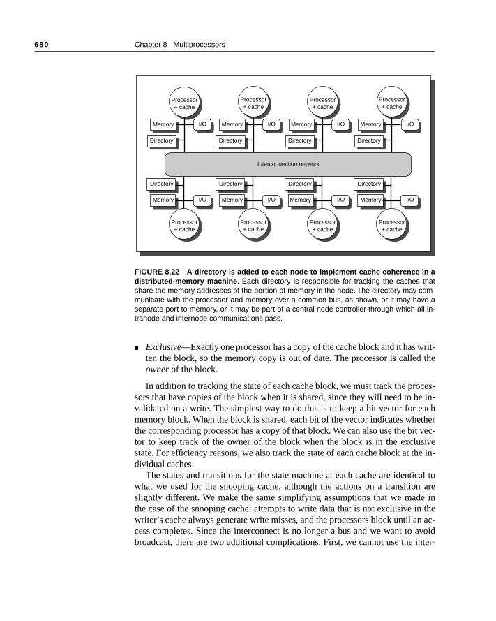
680 Chapter 8 Multiprocessors
writ-d the
ces-e in-
eachetherit vec-sivethe in-
tical ton aree inin thean ac- avoidinter-
■ Exclusive—Exactly one processor has a copy of the cache block and it has ten the block, so the memory copy is out of date. The processor is calleowner of the block.
In addition to tracking the state of each cache block, we must track the prosors that have copies of the block when it is shared, since they will need to bvalidated on a write. The simplest way to do this is to keep a bit vector for memory block. When the block is shared, each bit of the vector indicates whthe corresponding processor has a copy of that block. We can also use the btor to keep track of the owner of the block when the block is in the exclustate. For efficiency reasons, we also track the state of each cache block at dividual caches.
The states and transitions for the state machine at each cache are idenwhat we used for the snooping cache, although the actions on a transitioslightly different. We make the same simplifying assumptions that we madthe case of the snooping cache: attempts to write data that is not exclusive writer’s cache always generate write misses, and the processors block until cess completes. Since the interconnect is no longer a bus and we want tobroadcast, there are two additional complications. First, we cannot use the
FIGURE 8.22 A directory is added to each node to implement cache coherence in adistributed-memory machine. Each directory is responsible for tracking the caches thatshare the memory addresses of the portion of memory in the node. The directory may com-municate with the processor and memory over a common bus, as shown, or it may have aseparate port to memory, or it may be part of a central node controller through which all in-tranode and internode communications pass.
Interconnection network
Processor+ cache
Memory I/O
Directory
Processor+ cache
Memory I/O
Directory
Processor+ cache
Memory I/O
Directory
Processor+ cache
Memory I/O
Memory
Directory
Processor+ cache
Processor+ cache
Processor+ cache
Processor+ cache
Memory I/O Memory MemoryI/O I/O Memory I/O
Directory Directory Directory Directory
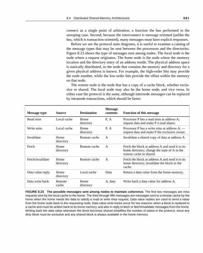
8.4 Distributed Shared-Memory Architectures 681
thelike thenses.
log ofctories.
y spacefor avideory
xclu-sa. Inplaced
.
s
s
connect as a single point of arbitration, a function the bus performed insnooping case. Second, because the interconnect is message oriented (unbus, which is transaction oriented), many messages must have explicit respo
Before we see the protocol state diagrams, it is useful to examine a catathe message types that may be sent between the processors and the direFigure 8.23 shows the type of messages sent among nodes. The local node is thenode where a request originates. The home node is the node where the memorlocation and the directory entry of an address reside. The physical addressis statically distributed, so the node that contains the memory and directory given physical address is known. For example, the high-order bits may prothe node number, while the low-order bits provide the offset within the memon that node.
The remote node is the node that has a copy of a cache block, whether esive or shared. The local node may also be the home node, and vice vereither case the protocol is the same, although internode messages can be reby intranode transactions, which should be faster.
Message type Source DestinationMessage contents Function of this message
Read miss Local cache Home directory
P, A Processor P has a read miss at address A; request data and make P a read sharer.
Write miss Local cache Home directory
P, A Processor P has a write miss at address A; —request data and make P the exclusive owner.
Invalidate Home directory
Remote cache A Invalidate a shared copy of data at address A
Fetch Home directory
Remote cache A Fetch the block at address A and send it to ithome directory; change the state of A in the remote cache to shared.
Fetch/invalidate Home directory
Remote cache A Fetch the block at address A and send it to ithome directory; invalidate the block in the cache.
Data value reply Home directory
Local cache Data Return a data value from the home memory.
Data write back Remote cache
Home directory
A, data Write back a data value for address A.
FIGURE 8.23 The possible messages sent among nodes to maintain coherence. The first two messages are missrequests sent by the local cache to the home. The third through fifth messages are messages sent to a remote cache by thehome when the home needs the data to satisfy a read or write miss request. Data value replies are used to send a valuefrom the home node back to the requesting node. Data value write backs occur for two reasons: when a block is replaced ina cache and must be written back to its home memory, and also in reply to fetch or fetch/invalidate messages from the home.Writing back the data value whenever the block becomes shared simplifies the number of states in the protocol, since anydirty block must be exclusive and any shared block is always available in the home memory.
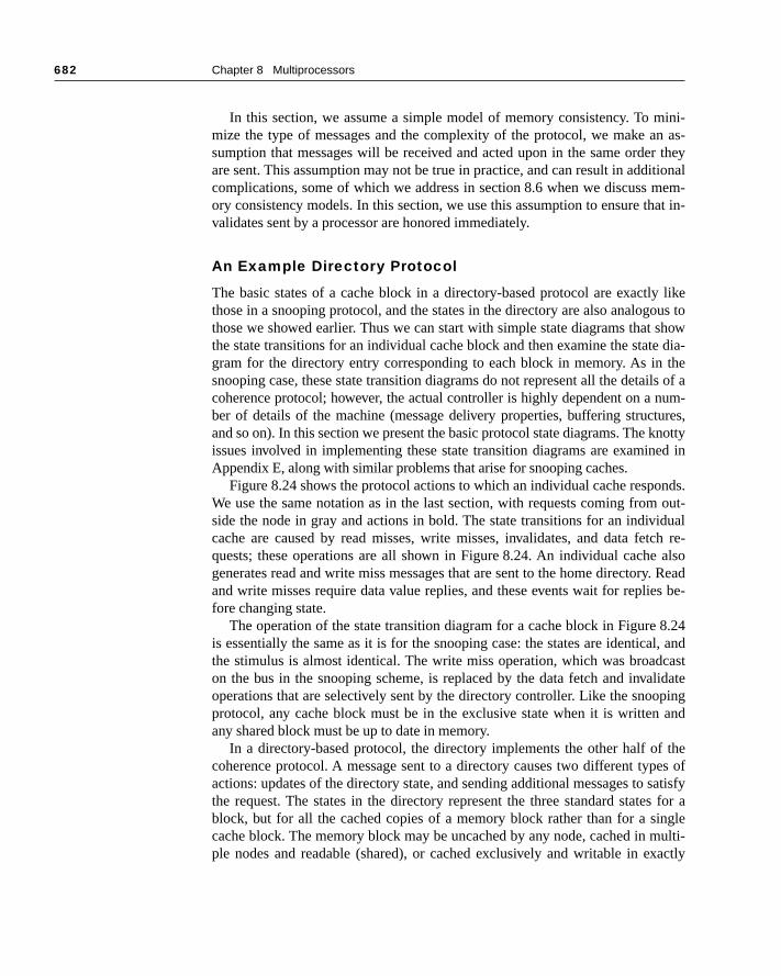
682 Chapter 8 Multiprocessors
ini-n as-r they
itionalem-
at in-
y likeous to showe dia- theils of anum-ures,knottyed in
nds. out-
idualtch re- alsoy. Reads be-
8.24al, andcastlidateping and
thees of
satisfys for angle
ulti-actly
In this section, we assume a simple model of memory consistency. To mmize the type of messages and the complexity of the protocol, we make asumption that messages will be received and acted upon in the same ordeare sent. This assumption may not be true in practice, and can result in addcomplications, some of which we address in section 8.6 when we discuss mory consistency models. In this section, we use this assumption to ensure thvalidates sent by a processor are honored immediately.
An Example Directory Protocol
The basic states of a cache block in a directory-based protocol are exactlthose in a snooping protocol, and the states in the directory are also analogthose we showed earlier. Thus we can start with simple state diagrams thatthe state transitions for an individual cache block and then examine the statgram for the directory entry corresponding to each block in memory. As insnooping case, these state transition diagrams do not represent all the detacoherence protocol; however, the actual controller is highly dependent on a ber of details of the machine (message delivery properties, buffering structand so on). In this section we present the basic protocol state diagrams. The issues involved in implementing these state transition diagrams are examinAppendix E, along with similar problems that arise for snooping caches.
Figure 8.24 shows the protocol actions to which an individual cache respoWe use the same notation as in the last section, with requests coming fromside the node in gray and actions in bold. The state transitions for an indivcache are caused by read misses, write misses, invalidates, and data fequests; these operations are all shown in Figure 8.24. An individual cachegenerates read and write miss messages that are sent to the home directorand write misses require data value replies, and these events wait for repliefore changing state.
The operation of the state transition diagram for a cache block in Figure is essentially the same as it is for the snooping case: the states are identicthe stimulus is almost identical. The write miss operation, which was broadon the bus in the snooping scheme, is replaced by the data fetch and invaoperations that are selectively sent by the directory controller. Like the snooprotocol, any cache block must be in the exclusive state when it is writtenany shared block must be up to date in memory.
In a directory-based protocol, the directory implements the other half ofcoherence protocol. A message sent to a directory causes two different typactions: updates of the directory state, and sending additional messages to the request. The states in the directory represent the three standard stateblock, but for all the cached copies of a memory block rather than for a sicache block. The memory block may be uncached by any node, cached in mple nodes and readable (shared), or cached exclusively and writable in ex
8.4 Distributed Shared-Memory Architectures 683
set of
itcises, the set
sagesmiss,
one node. In addition to the state of each block, the directory must track the processors that have a copy of a block; we use a set called Sharers to perform thisfunction. In small-scale machines (≤ 128 nodes), this set is typically kept as a bvector. In larger machines, other techniques, which we discuss in the Exerare needed. Directory requests need to update the set Sharers and also readto perform invalidations.
Figure 8.25 shows the actions taken at the directory in response to mesreceived. The directory receives three different requests: read miss, write
FIGURE 8.24 State transition diagram for an individual cache block in a directory-based system. Requests by the local processor are shown in black and those from the homedirectory are shown in gray. The states are identical to those in the snooping case, and thetransactions are very similar, with explicit invalidate and write-back requests replacing thewrite misses that were formerly broadcast on the bus. As we did for the snooping controller,we assume that an attempt to write a shared cache block is treated as a miss; in practice,such a transaction can be treated as an ownership request or upgrade request and can de-liver ownership without requiring that the cache block be fetched.
Exclusive(read/write)
CPU write hitCPU read hit
Fetchinvalidate
CPU write
Sen
d w
rite
mis
s m
essa
ge
Fetch
CPU read
miss
Data w
rite-
back
Send w
rite m
iss m
essa
geCPU w
rite
Send read miss message
Read miss
CPU read
CPU read hit
CPU write miss
Data write-backWrite miss
CPUreadmiss
Invalid
Invalidate
Data w
rite-
back;
read
miss
Shared(read only)
Dat
a w
rite
-bac
k

684 Chapter 8 Multiprocessors
own ine alllified
ue andtion. eivedopy in
mory made
and data write back. The messages sent in response by the directory are shbold, while the updating of the set Sharers is shown in bold italics. Becausthe stimulus messages are external, all actions are shown in gray. Our simpprotocol assumes that some actions are atomic, such as requesting a valsending it to another node; a realistic implementation cannot use this assump
To understand these directory operations, let’s examine the requests recand actions taken state by state. When a block is in the uncached state the cmemory is the current value, so the only possible requests for that block are
■ Read miss—The requesting processor is sent the requested data from meand the requestor is made the only sharing node. The state of the block isshared.
FIGURE 8.25 The state transition diagram for the directory has the same states andstructure as the transition diagram for an individual cache. All actions are in gray be-cause they are all externally caused. Bold indicates the action taken by the directory in re-sponse to the request. Bold italics indicate an action that updates the sharing set, Sharers,as opposed to sending a message.
Exclusive(read/write)
Datawrite-back
Write miss
Dat
a va
lue
rep
ly;
Sh
arer
s={P
}
Sh
arer
s={}
Inva
lidat
e; S
harer
s={P
}; dat
a valu
e rep
ly
Read miss
Data value replySharers=Sharers+{P}
Data value reply; Sharers={P}
Writemiss
Fetch/invalidateData value replySharers={P}
Readmiss
Uncached
Fetch
; dat
a valu
e rep
ly; S
harer
s=Shar
ers+
{P}
Read
miss
Writ
e m
iss
Shared(read only)
8.4 Distributed Shared-Memory Architectures 685
Shar-y is
same
mory
thetain theive.
ld inre are
useses the sentsor isr that
orectoryrer set
nerich its is setve.
s insincedix E
onalcursomeiginalown-ck tothey
■ Write miss—The requesting processor is sent the value and becomes the ing node. The block is made exclusive to indicate that the only valid copcached. Sharers indicates the identity of the owner.
When the block is in the shared state the memory value is up to date, so thetwo requests can occur:
■ Read miss—The requesting processor is sent the requested data from meand the requesting processor is added to the sharing set.
■ Write miss—The requesting processor is sent the value. All processors inset Sharers are sent invalidate messages, and the Sharers set is to conidentity of the requesting processor. The state of the block is made exclus
When the block is in the exclusive state the current value of the block is hethe cache of the processor identified by the set sharers (the owner), so thethree possible directory requests:
■ Read miss—The owner processor is sent a data fetch message, which cathe state of the block in the owner’s cache to transition to shared and causowner to send the data to the directory, where it is written to memory andback to the requesting processor. The identity of the requesting procesadded to the set sharers, which still contains the identity of the processowas the owner (since it still has a readable copy).
■ Data write-back—The owner processor is replacing the block and therefmust write it back. This makes the memory copy up to date (the home direessentially becomes the owner), the block is now uncached, and the shais empty.
■ Write miss—The block has a new owner. A message is sent to the old owcausing the cache to send the value of the block to the directory, from whis sent to the requesting processor, which becomes the new owner. Sharerto the identity of the new owner, and the state of the block remains exclusi
This state transition diagram in Figure 8.25 is a simplification, just as it wathe snooping cache case. In the directory case it is a larger simplification, our assumption that bus transactions are atomic no longer applies. Appenexplores these issues in depth.
In addition, the directory protocols used in real machines contain additioptimizations. In particular, in our protocol here when a read or write miss ocfor a block that is exclusive, the block is first sent to the directory at the hnode. From there it is stored into the home memory and also sent to the orrequesting node. Many protocols in real machines forward the data from the er node to the requesting node directly (as well as performing the write bathe home). Such optimizations may not add complexity to the protocol, but often move the complexity from one part of the design to another.
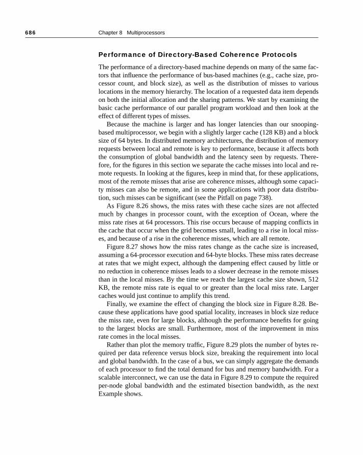
686 Chapter 8 Multiprocessors
e fac-e, pro-riousends thet the
ping-lockory
s bothhere-nd re-tions,capaci-tribu-
fectede theicts inmiss-
eased,crease
tle ormissesn, 512arger
Be-educegoingmiss
s re- local
andsFor aquired next
Performance of Directory-Based Coherence Protocols
The performance of a directory-based machine depends on many of the samtors that influence the performance of bus-based machines (e.g., cache sizcessor count, and block size), as well as the distribution of misses to valocations in the memory hierarchy. The location of a requested data item depon both the initial allocation and the sharing patterns. We start by examiningbasic cache performance of our parallel program workload and then look aeffect of different types of misses.
Because the machine is larger and has longer latencies than our snoobased multiprocessor, we begin with a slightly larger cache (128 KB) and a bsize of 64 bytes. In distributed memory architectures, the distribution of memrequests between local and remote is key to performance, because it affectthe consumption of global bandwidth and the latency seen by requests. Tfore, for the figures in this section we separate the cache misses into local amote requests. In looking at the figures, keep in mind that, for these applicamost of the remote misses that arise are coherence misses, although some ty misses can also be remote, and in some applications with poor data distion, such misses can be significant (see the Pitfall on page 738).
As Figure 8.26 shows, the miss rates with these cache sizes are not afmuch by changes in processor count, with the exception of Ocean, whermiss rate rises at 64 processors. This rise occurs because of mapping conflthe cache that occur when the grid becomes small, leading to a rise in local es, and because of a rise in the coherence misses, which are all remote.
Figure 8.27 shows how the miss rates change as the cache size is incrassuming a 64-processor execution and 64-byte blocks. These miss rates deat rates that we might expect, although the dampening effect caused by litno reduction in coherence misses leads to a slower decrease in the remote than in the local misses. By the time we reach the largest cache size showKB, the remote miss rate is equal to or greater than the local miss rate. Lcaches would just continue to amplify this trend.
Finally, we examine the effect of changing the block size in Figure 8.28. cause these applications have good spatial locality, increases in block size rthe miss rate, even for large blocks, although the performance benefits for to the largest blocks are small. Furthermore, most of the improvement in rate comes in the local misses.
Rather than plot the memory traffic, Figure 8.29 plots the number of bytequired per data reference versus block size, breaking the requirement intoand global bandwidth. In the case of a bus, we can simply aggregate the demof each processor to find the total demand for bus and memory bandwidth. scalable interconnect, we can use the data in Figure 8.29 to compute the reper-node global bandwidth and the estimated bisection bandwidth, as theExample shows.
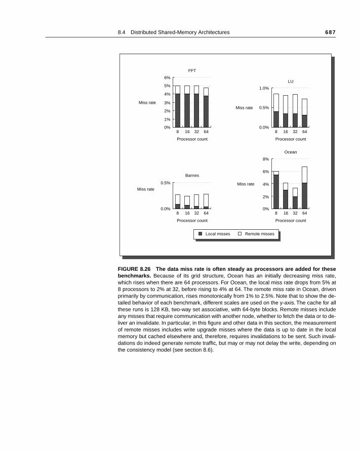
8.4 Distributed Shared-Memory Architectures 687
FIGURE 8.26 The data miss rate is often steady as processors are added for thesebenchmarks. Because of its grid structure, Ocean has an initially decreasing miss rate,which rises when there are 64 processors. For Ocean, the local miss rate drops from 5% at8 processors to 2% at 32, before rising to 4% at 64. The remote miss rate in Ocean, drivenprimarily by communication, rises monotonically from 1% to 2.5%. Note that to show the de-tailed behavior of each benchmark, different scales are used on the y-axis. The cache for allthese runs is 128 KB, two-way set associative, with 64-byte blocks. Remote misses includeany misses that require communication with another node, whether to fetch the data or to de-liver an invalidate. In particular, in this figure and other data in this section, the measurementof remote misses includes write upgrade misses where the data is up to date in the localmemory but cached elsewhere and, therefore, requires invalidations to be sent. Such invali-dations do indeed generate remote traffic, but may or may not delay the write, depending onthe consistency model (see section 8.6).
Miss rate
0%
3%
2%
1%
8 16 32
Processor count
FFT
64
6%
4%
5%
Miss rate
0.0%
0.5%
8 16 32
Processor count
LU
64
1.0%
Miss rate
0%
4%
2%
8 16 32
Processor count
Ocean
64
8%
6%
Miss rate
0.0%8 16 32
Processor count
Barnes
64
0.5%
Local misses Remote misses
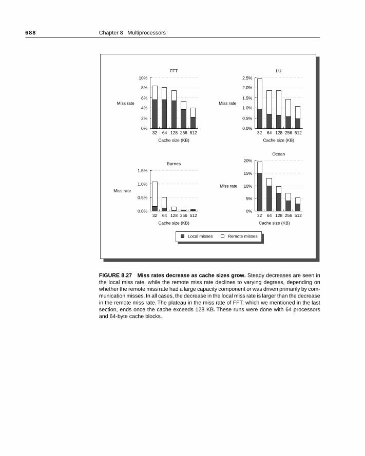
688 Chapter 8 Multiprocessors
FIGURE 8.27 Miss rates decrease as cache sizes grow. Steady decreases are seen inthe local miss rate, while the remote miss rate declines to varying degrees, depending onwhether the remote miss rate had a large capacity component or was driven primarily by com-munication misses. In all cases, the decrease in the local miss rate is larger than the decreasein the remote miss rate. The plateau in the miss rate of FFT, which we mentioned in the lastsection, ends once the cache exceeds 128 KB. These runs were done with 64 processorsand 64-byte cache blocks.
Miss rate
0%
4%
2%
32 64 128
Cache size (KB)
FFT
256 512
10%
6%
8%
Miss rate
0.0%
1.0%
0.5%
32 64 128
Cache size (KB)
LU
Ocean
256 512
2.5%
1.5%
2.0%
Miss rate
0.0%
0.5%
32 64 128
Cache size (KB)
Barnes
256 512
1.5%
1.0% Miss rate
0%
10%
5%
32 64 128
Cache size (KB)
256 512
20%
15%
Local misses Remote misses
8.4 Distributed Shared-Memory Architectures 689
E X A M P L E Assume a multiprocessor with 64 200-MHz processors that sustains one memory reference per clock. For a 64-byte block size, the remote miss rate is 0.7%. Find the per-node and estimated bisection bandwidth for FFT. Assume that the processor does not stall for remote memory re-quests; this might be true if, for example, all remote data were prefetched. How do these bandwidth requirements compare to various interconnec-tion technologies?
FIGURE 8.28 Data miss rate versus block size assuming a 128-KB cache and 64 pro-cessors in total. Although difficult to see, the coherence miss rate in Barnes actually risesfor the largest block size, just as in the last section.
Miss rate
0%
4%
6%
2%
16 32 64
Block size (bytes)
FFT
128
12%
8%
10%
Miss rate
0%
2%
1%
16 32 64
Block size (bytes)
LU
128
4%
3%
Miss rate
0%
5%
10%
16 32 64
Block size (bytes)
Ocean
128
15%
Miss rate
0.0%
0.1%
16 32 64
Block size (bytes)
Barnes
128
0.3%
0.2%
Local misses Remote misses

690 Chapter 8 Multiprocessors
A N S W E R The per-node bandwidth is simply the number of data bytes per reference times the reference rate: 0.7% × 200 × 64 = 90 MB/sec. This rate is about half the bandwidth of the fastest scalable MPP interconnects available in 1995. The FFT per-node bandwidth demand exceeds the fastest ATM in-terconnects available in 1995 by about a factor of 5, and slightly exceeds next-generation ATM.
FFT performs all-to-all communication, so the bisection bandwidth is equal to 32 times the per-node bandwidth, or 2880 MB/sec. For a 64-pro-cessor machine arranged in a 2D mesh, the bisection bandwidth grows as the square root of the number of processors. Thus for 64 processors
FIGURE 8.29 The number of bytes per data reference climbs steadily as block size isincreased. These data can be used to determine the bandwidth required per node both in-ternally and globally. The data assumes a 128-KB cache for each of 64 processors.
Bytes per datareference
Bytes per datareference
Bytes per datareference
Bytes per datareference
0.0
2.0
3.0
1.0
16 32 64
Block size (bytes)
FFT
128
6.0
4.0
5.0
0.0
0.2
0.3
0.1
16 32 64
Block size (bytes)
LU
128
0.6
0.4
0.5
0.0
2.0
4.0
6.0
5.0
3.0
1.0
16 32 64
Block size (bytes)
Ocean
128
7.0
0.0
0.1
16 32 64
Block size (bytes)
Barnes
128
0.4
0.3
0.2
Local Global
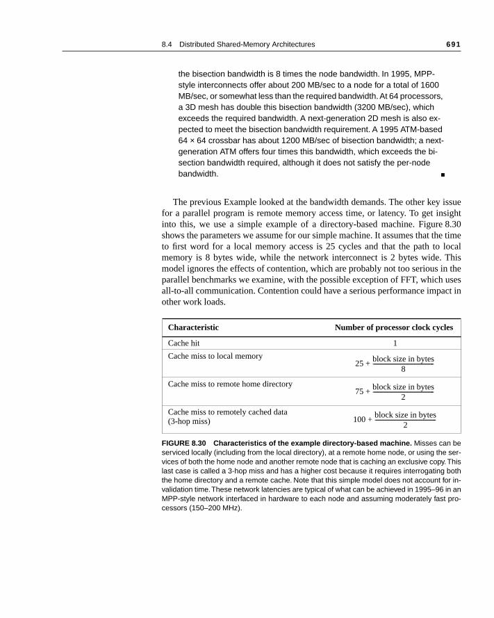
8.4 Distributed Shared-Memory Architectures 691
issuesight 8.30e timelocalhis
n theusesct in
the bisection bandwidth is 8 times the node bandwidth. In 1995, MPP-style interconnects offer about 200 MB/sec to a node for a total of 1600 MB/sec, or somewhat less than the required bandwidth. At 64 processors, a 3D mesh has double this bisection bandwidth (3200 MB/sec), which exceeds the required bandwidth. A next-generation 2D mesh is also ex-pected to meet the bisection bandwidth requirement. A 1995 ATM-based 64 × 64 crossbar has about 1200 MB/sec of bisection bandwidth; a next-generation ATM offers four times this bandwidth, which exceeds the bi-section bandwidth required, although it does not satisfy the per-node bandwidth. ■
The previous Example looked at the bandwidth demands. The other key for a parallel program is remote memory access time, or latency. To get ininto this, we use a simple example of a directory-based machine. Figureshows the parameters we assume for our simple machine. It assumes that thto first word for a local memory access is 25 cycles and that the path to memory is 8 bytes wide, while the network interconnect is 2 bytes wide. Tmodel ignores the effects of contention, which are probably not too serious iparallel benchmarks we examine, with the possible exception of FFT, which all-to-all communication. Contention could have a serious performance impaother work loads.
Characteristic Number of processor clock cycles
Cache hit 1
Cache miss to local memory
Cache miss to remote home directory
Cache miss to remotely cached data (3-hop miss)
FIGURE 8.30 Characteristics of the example directory-based machine. Misses can beserviced locally (including from the local directory), at a remote home node, or using the ser-vices of both the home node and another remote node that is caching an exclusive copy. Thislast case is called a 3-hop miss and has a higher cost because it requires interrogating boththe home directory and a remote cache. Note that this simple model does not account for in-validation time. These network latencies are typical of what can be achieved in 1995–96 in anMPP-style network interfaced in hardware to each node and assuming moderately fast pro-cessors (150–200 MHz).
25block size in bytes
8--------------------------------------------+
75block size in bytes
2--------------------------------------------+
100block size in bytes
2--------------------------------------------+

692 Chapter 8 Multiprocessors
, as- types, re- totalhe lo-s fair-easingte in- also. inant
oulds the ac-
al sim-ies:era-ce ofuces
ate a andes inroto-
hendader, arele. Itas theries.
ning
Figure 8.31 shows the cost in cycles for the average memory referencesuming the parameters in Figure 8.30. Only the latencies for each referenceare counted. Each bar indicates the contribution from cache hits, local missemote misses, and 3-hop remote misses. The cost is influenced by thefrequency of cache misses and upgrades, as well as by the distribution of tcation where the miss is satisfied. The cost for a remote memory reference ily steady as the processor count is increased, except for Ocean. The incrmiss rate in Ocean for 64 processors is clear in Figure 8.26. As the miss racreases, we should expect the time spent on memory references to increase
Although Figure 8.31 shows the memory access cost, which is the dommultiprocessor cost in these benchmarks, a complete performance model wneed to consider the effect of contention in the memory system, as well alosses arising from synchronization delays. In section 8.8 we will look at thetual performance of the SGI Challenge system on these benchmarks.
The coherence protocols that we have discussed so far have made severplifying assumptions. In practice, real protocols must deal with two realitnonatomicity of operations and finite buffering. We have seen why certain options (such as a write miss) cannot be atomic. In DSM machines the presenonly a finite number of buffers to hold message requests and replies introdadditional possibilities for deadlock. The challenge for the designer is to creprotocol that works correctly and without deadlock, using nonatomic actionsfinite buffers as the building blocks. These factors are fundamental challengall parallel machines, and the solutions are applicable to a wide variety of pcol design environments, both in hardware and in software.
Because this material is extremely complex and not necessary to comprethe rest of the chapter, we have placed it in Appendix E. For the interested reAppendix E shows how the specific problems in our coherence protocolssolved and illustrates the general principles that are more globally applicabdescribes the problems arising in snooping cache implementations, as well more complex problems that arise in more distributed systems using directoIf you want to understand how these machines really work and why desigthem is such a challenge, go read Appendix E!
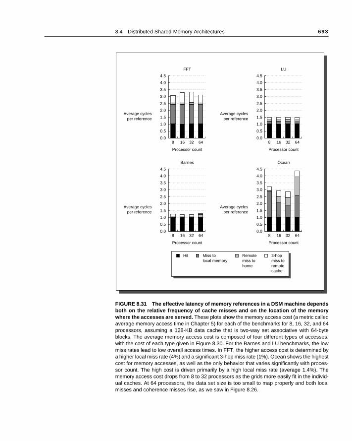
8.4 Distributed Shared-Memory Architectures 693
FIGURE 8.31 The effective latency of memory references in a DSM machine dependsboth on the relative frequency of cache misses and on the location of the memorywhere the accesses are served. These plots show the memory access cost (a metric calledaverage memory access time in Chapter 5) for each of the benchmarks for 8, 16, 32, and 64processors, assuming a 128-KB data cache that is two-way set associative with 64-byteblocks. The average memory access cost is composed of four different types of accesses,with the cost of each type given in Figure 8.30. For the Barnes and LU benchmarks, the lowmiss rates lead to low overall access times. In FFT, the higher access cost is determined bya higher local miss rate (4%) and a significant 3-hop miss rate (1%). Ocean shows the highestcost for memory accesses, as well as the only behavior that varies significantly with proces-sor count. The high cost is driven primarily by a high local miss rate (average 1.4%). Thememory access cost drops from 8 to 32 processors as the grids more easily fit in the individ-ual caches. At 64 processors, the data set size is too small to map properly and both localmisses and coherence misses rise, as we saw in Figure 8.26.
Average cyclesper reference
0.0
1.5
1.0
2.0
0.5
8 16 32
Processor count
FFT
64
4.5
2.5
3.0
3.5
4.0
Average cyclesper reference
0.0
1.5
1.0
2.0
0.5
8 16 32
Processor count
LU
64
4.5
2.5
3.0
3.5
4.0
Average cyclesper reference
0.0
1.5
1.0
2.0
0.5
8 16 32
Processor count
Barnes
64
4.5
2.5
3.0
3.5
4.0
Average cyclesper reference
0.0
1.5
1.0
2.0
0.5
8 16 32
Processor count
Ocean
64
4.5
2.5
3.0
3.5
4.0
Hit Miss tolocal memory
Remotemiss tohome
3-hopmiss toremotecache
694 Chapter 8 Multiprocessors
inesma-ter-anded us- be
enceniza- addi-. We
evel syn-
veralfor-
is am-
tionses.ives,heresee va- anddwareram-icky.build
see want freeet theresss 1 if
Synchronization mechanisms are typically built with user-level software routthat rely on hardware-supplied synchronization instructions. For smaller chines or low-contention situations, the key hardware capability is an uninruptible instruction or instruction sequence capable of atomically retrieving changing a value. Software synchronization mechanisms are then constructing this capability. For example, we will see how very efficient spin locks canbuilt using a simple hardware synchronization instruction and the cohermechanism. In larger-scale machines or high-contention situations, synchrotion can become a performance bottleneck, because contention introducestional delays and because latency is potentially greater in such a machinewill see how contention can arise in implementing some common user-lsynchronization operations and examine more powerful hardware-supportedchronization primitives that can reduce contention as well as latency.
We begin by examining the basic hardware primitives, then construct sewell-known synchronization routines with the primitives, and then turn to permance problems in larger machines and solutions for those problems.
Basic Hardware Primitives
The key ability we require to implement synchronization in a multiprocessorset of hardware primitives with the ability to atomically read and modify a meory location. Without such a capability, the cost of building basic synchronizaprimitives will be too high and will increase as the processor count increaThere are a number of alternative formulations of the basic hardware primitall of which provide the ability to atomically read and modify a location, togetwith some way to tell if the read and write were performed atomically. Thhardware primitives are the basic building blocks that are used to build a widriety of user-level synchronization operations, including things such as locksbarriers. In general, architects do not expect users to employ the basic harprimitives, but instead expect that the primitives will be used by system progmers to build a synchronization library, a process that is often complex and trLet’s start with one such hardware primitive and show how it can be used to some basic synchronization operations.
One typical operation for building synchronization operations is the atomicexchange, which interchanges a value in a register for a value in memory. Tohow to use this to build a basic synchronization operation, assume that weto build a simple lock where the value 0 is used to indicate that the lock isand a 1 is used to indicate that the lock is unavailable. A processor tries to slock by doing an exchange of 1, which is in a register, with the memory addcorresponding to the lock.The value returned from the exchange instruction i
8.5 Synchronization
8.5 Synchronization 695
lattere from
imul-formen itple-
sibleech-vari-
mentmem- exe-
couldd in aiza-
nroni-d ex-h we
era-mem- readple-ns be-
n re- wasearsppearother
dnkeden theo in-ed to loadeds
some other processor had already claimed access and 0 otherwise. In thecase, the value is also changed to be 1, preventing any competing exchangalso retrieving a 0.
For example, consider two processors that each try to do the exchange staneously: This race is broken since exactly one of the processors will perthe exchange first, returning 0, and the second processor will return 1 whdoes the exchange. The key to using the exchange (or swap) primitive to imment synchronization is that the operation is atomic: the exchange is indiviand two simultaneous exchanges will be ordered by the write serialization manisms. It is impossible for two processors trying to set the synchronization able in this manner to both think they have simultaneously set the variable.
There are a number of other atomic primitives that can be used to implesynchronization. They all have the key property that they read and update a ory value in such a manner that we can tell whether or not the two operationscuted atomically. One operation present in many older machines is test-and-set,which tests a value and sets it if the value passes the test. For example, wedefine an operation that tested for 0 and set the value to 1, which can be usefashion similar to how we used atomic exchange. Another atomic synchrontion primitive is fetch-and-increment: it returns the value of a memory locatioand atomically increments it. By using the value 0 to indicate that the synchzation variable is unclaimed, we can use fetch-and-increment, just as we usechange. There are other uses of operations like fetch-and-increment, whicwill see shortly.
A slightly different approach to providing this atomic read-and-update option has been used in some recent machines. Implementing a single atomic ory operation introduces some challenges, since it requires both a memoryand a write in a single, uninterruptible instruction. This complicates the immentation of coherence, since the hardware cannot allow any other operatiotween the read and the write, and yet must not deadlock.
An alternative is to have a pair of instructions where the second instructioturns a value from which it can be deduced whether the pair of instructionsexecuted as if the instructions were atomic. The pair of instructions appatomic if it appears as if all other operations executed by any processor abefore or after the pair. Thus when an instruction pair appears atomic, no processor can change the value between the instruction pair.
The pair of instructions includes a special load called a load linked or loadlocked and a special store called a store conditional. These instructions are usein sequence: If the contents of the memory location specified by the load liare changed before the store conditional to the same address occurs, thstore conditional fails. If the processor does a context switch between the twstructions, then the store conditional also fails. The store conditional is definreturn a value indicating whether or not the store was successful. Since thelinked returns the initial value and the store conditional returns 1 if it succe
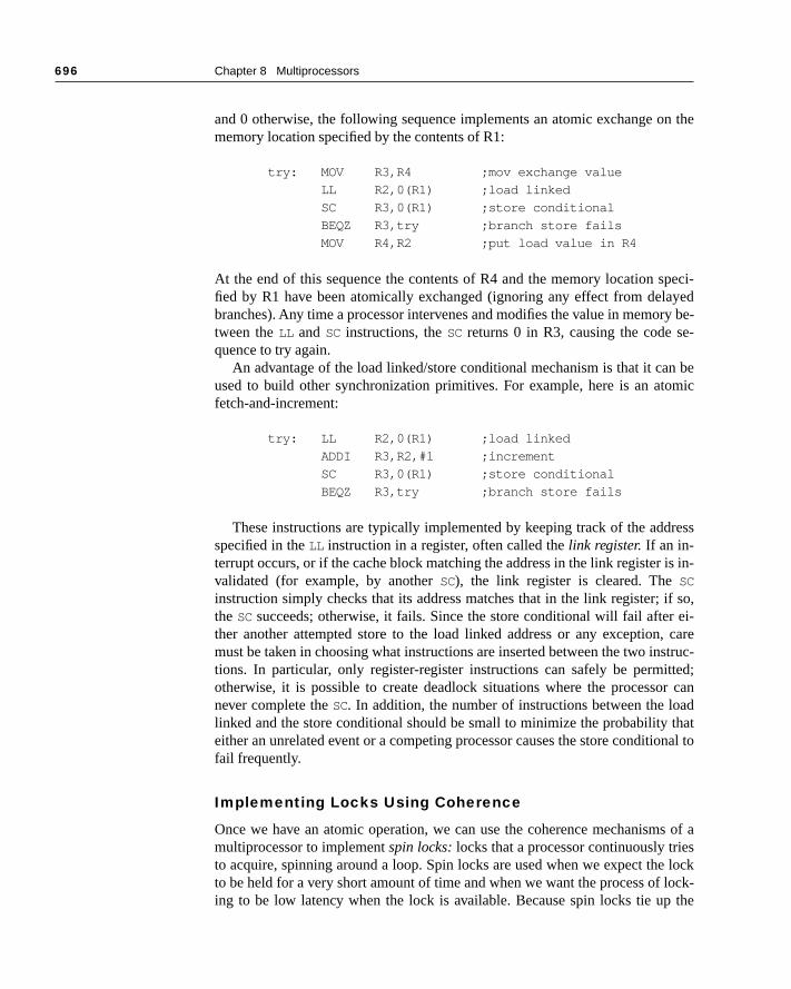
696 Chapter 8 Multiprocessors
n the
peci-yed
ry be-e-
n bemic
ress
is in-
if so, ei-, carestruc-ted;r canadthatonal to
s of as locklock- the
and 0 otherwise, the following sequence implements an atomic exchange omemory location specified by the contents of R1:
try: MOV R3,R4 ;mov exchange value
LL R2,0(R1) ;load linked
SC R3,0(R1) ;store conditional
BEQZ R3,try ;branch store fails
MOV R4,R2 ;put load value in R4
At the end of this sequence the contents of R4 and the memory location sfied by R1 have been atomically exchanged (ignoring any effect from delabranches). Any time a processor intervenes and modifies the value in memotween the LL and SC instructions, the SC returns 0 in R3, causing the code squence to try again.
An advantage of the load linked/store conditional mechanism is that it caused to build other synchronization primitives. For example, here is an atofetch-and-increment:
try: LL R2,0(R1) ;load linked
ADDI R3,R2,#1 ;increment
SC R3,0(R1) ;store conditional
BEQZ R3,try ;branch store fails
These instructions are typically implemented by keeping track of the addspecified in the LL instruction in a register, often called the link register. If an in-terrupt occurs, or if the cache block matching the address in the link register validated (for example, by another SC), the link register is cleared. The SC
instruction simply checks that its address matches that in the link register; the SC succeeds; otherwise, it fails. Since the store conditional will fail afterther another attempted store to the load linked address or any exceptionmust be taken in choosing what instructions are inserted between the two intions. In particular, only register-register instructions can safely be permitotherwise, it is possible to create deadlock situations where the processonever complete the SC. In addition, the number of instructions between the lolinked and the store conditional should be small to minimize the probability either an unrelated event or a competing processor causes the store conditifail frequently.
Implementing Locks Using Coherence
Once we have an atomic operation, we can use the coherence mechanismmultiprocessor to implement spin locks: locks that a processor continuously trieto acquire, spinning around a loop. Spin locks are used when we expect theto be held for a very short amount of time and when we want the process of ing to be low latency when the lock is available. Because spin locks tie up

8.5 Synchronization 697
te in
co-uallyether
simplywhose
he co-van-ing
copy lock.lity in in theroces-
atheruires
op di-g toriteusive
adsble.r firstg until races locke andsers
o setssor vari-de to
processor, waiting in a loop for the lock to become free, they are inappropriasome circumstances.
The simplest implementation, which we would use if there were no cacheherence, would keep the lock variables in memory. A processor could contintry to acquire the lock using an atomic operation, say exchange, and test whthe exchange returned the lock as free. To release the lock, the processor stores the value 0 to the lock. Here is the code sequence to lock a spin lock address is in R1 using an atomic exchange:
LI R2,#1
lockit: EXCH R2,0(R1) ;atomic exchange
BNEZ R2,lockit ;already locked?
If our machine supports cache coherence, we can cache the locks using therence mechanism to maintain the lock value coherently. This has two adtages. First, it allows an implementation where the process of “spinning” (tryto test and acquire the lock in a tight loop) could be done on a local cachedrather than requiring a global memory access on each attempt to acquire theThe second advantage comes from the observation that there is often localock accesses: that is, the processor that used the lock last will use it againnear future. In such cases, the lock value may reside in the cache of that psor, greatly reducing the time to acquire the lock.
To obtain the first advantage—being able to spin on a local cached copy rthan generating a memory request for each attempt to acquire the lock—reqa change in our simple spin procedure. Each attempt to exchange in the lorectly above requires a write operation. If multiple processors are attemptinget the lock, each will generate the write. Most of these writes will lead to wmisses, since each processor is trying to obtain the lock variable in an exclstate.
Thus we should modify our spin-lock procedure so that it spins by doing reon a local copy of the lock until it successfully sees that the lock is availaThen it attempts to acquire the lock by doing a swap operation. A processoreads the lock variable to test its state. A processor keeps reading and testinthe value of the read indicates that the lock is unlocked. The processor thenagainst all other processes that were similarly “spin waiting” to see who canthe variable first. All processes use a swap instruction that reads the old valustores a 1 into the lock variable. The single winner will see the 0, and the lowill see a 1 that was placed there by the winner. (The losers will continue tthe variable to the locked value, but that doesn’t matter.) The winning proceexecutes the code after the lock and, when finished, stores a 0 into the lockable to release the lock, which starts the race all over again. Here is the coperform this spin lock (remember that 0 is unlocked and 1 is locked):
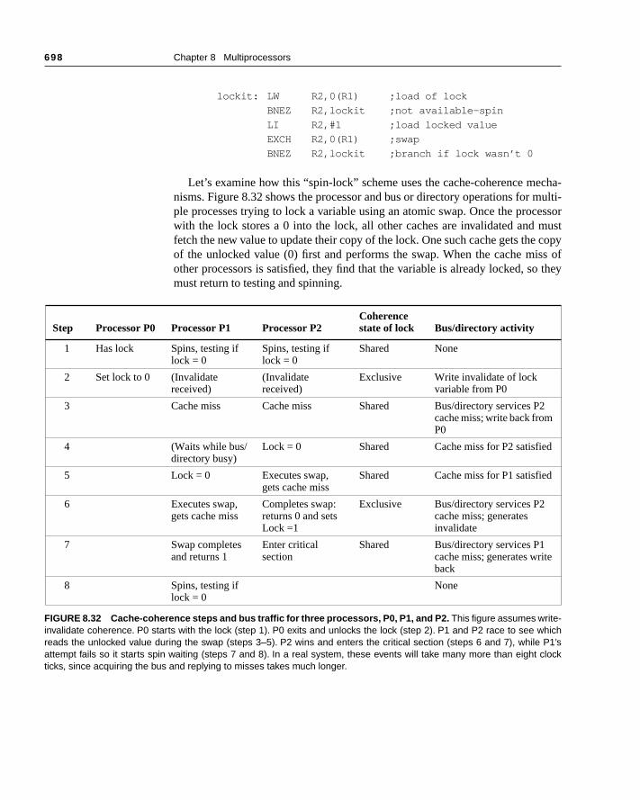
698 Chapter 8 Multiprocessors
cha-multi-essormust copyss of they
lockit: LW R2,0(R1) ;load of lock
BNEZ R2,lockit ;not available-spin
LI R2,#1 ;load locked value
EXCH R2,0(R1) ;swap
BNEZ R2,lockit ;branch if lock wasn’t 0
Let’s examine how this “spin-lock” scheme uses the cache-coherence menisms. Figure 8.32 shows the processor and bus or directory operations for ple processes trying to lock a variable using an atomic swap. Once the procwith the lock stores a 0 into the lock, all other caches are invalidated and fetch the new value to update their copy of the lock. One such cache gets theof the unlocked value (0) first and performs the swap. When the cache miother processors is satisfied, they find that the variable is already locked, somust return to testing and spinning.
Step Processor P0 Processor P1 Processor P2Coherence state of lock Bus/directory activity
1 Has lock Spins, testing if lock = 0
Spins, testing if lock = 0
Shared None
2 Set lock to 0 (Invalidate received)
(Invalidate received)
Exclusive Write invalidate of lock variable from P0
3 Cache miss Cache miss Shared Bus/directory services P2cache miss; write back from P0
4 (Waits while bus/directory busy)
Lock = 0 Shared Cache miss for P2 satisfied
5 Lock = 0 Executes swap, gets cache miss
Shared Cache miss for P1 satisfied
6 Executes swap, gets cache miss
Completes swap: returns 0 and sets Lock =1
Exclusive Bus/directory services P2 cache miss; generates invalidate
7 Swap completes and returns 1
Enter critical section
Shared Bus/directory services P1 cache miss; generates write back
8 Spins, testing if lock = 0
None
FIGURE 8.32 Cache-coherence steps and bus traffic for three processors, P0, P1, and P2. This figure assumes write-invalidate coherence. P0 starts with the lock (step 1). P0 exits and unlocks the lock (step 2). P1 and P2 race to see whichreads the unlocked value during the swap (steps 3–5). P2 wins and enters the critical section (steps 6 and 7), while P1’sattempt fails so it starts spin waiting (steps 7 and 8). In a real system, these events will take many more than eight clockticks, since acquiring the bus and replying to misses takes much longer.
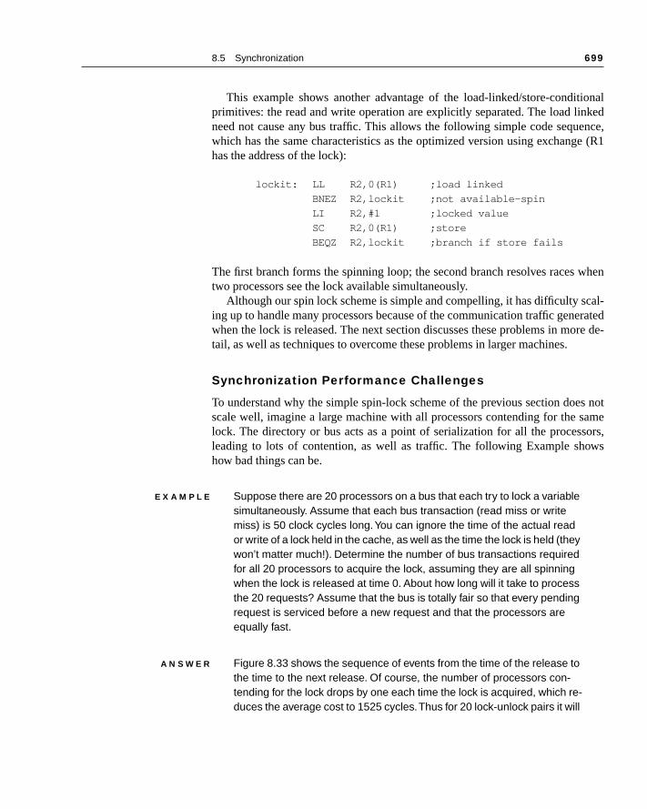
8.5 Synchronization 699
ionalked
ence,e (R1
when
cal-ratedre de-
s notsamesors,ws
This example shows another advantage of the load-linked/store-conditprimitives: the read and write operation are explicitly separated. The load linneed not cause any bus traffic. This allows the following simple code sequwhich has the same characteristics as the optimized version using exchanghas the address of the lock):
lockit: LL R2,0(R1) ;load linked
BNEZ R2,lockit ;not available-spin
LI R2,#1 ;locked value
SC R2,0(R1) ;store
BEQZ R2,lockit ;branch if store fails
The first branch forms the spinning loop; the second branch resolves racestwo processors see the lock available simultaneously.
Although our spin lock scheme is simple and compelling, it has difficulty sing up to handle many processors because of the communication traffic genewhen the lock is released. The next section discusses these problems in motail, as well as techniques to overcome these problems in larger machines.
Synchronization Performance Challenges
To understand why the simple spin-lock scheme of the previous section doescale well, imagine a large machine with all processors contending for the lock. The directory or bus acts as a point of serialization for all the procesleading to lots of contention, as well as traffic. The following Example shohow bad things can be.
E X A M P L E Suppose there are 20 processors on a bus that each try to lock a variable simultaneously. Assume that each bus transaction (read miss or write miss) is 50 clock cycles long. You can ignore the time of the actual read or write of a lock held in the cache, as well as the time the lock is held (they won’t matter much!). Determine the number of bus transactions required for all 20 processors to acquire the lock, assuming they are all spinning when the lock is released at time 0. About how long will it take to process the 20 requests? Assume that the bus is totally fair so that every pending request is serviced before a new request and that the processors are equally fast.
A N S W E R Figure 8.33 shows the sequence of events from the time of the release to the time to the next release. Of course, the number of processors con-tending for the lock drops by one each time the lock is acquired, which re-duces the average cost to 1525 cycles. Thus for 20 lock-unlock pairs it will
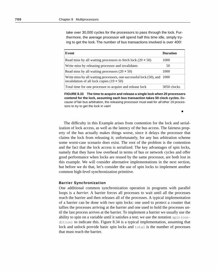
700 Chapter 8 Multiprocessors
ial- prop-r thatmentionlocks,offer lost intion,other
allelsestationr thates un-e the
thats
take over 30,000 cycles for the processors to pass through the lock. Fur-thermore, the average processor will spend half this time idle, simply try-ing to get the lock. The number of bus transactions involved is over 400!
■
The difficulty in this Example arises from contention for the lock and serization of lock access, as well as the latency of the bus access. The fairnesserty of the bus actually makes things worse, since it delays the processoclaims the lock from releasing it; unfortunately, for any bus arbitration schesome worst-case scenario does exist. The root of the problem is the conteand the fact that the lock access is serialized. The key advantages of spin namely that they have low overhead in terms of bus or network cycles and good performance when locks are reused by the same processor, are boththis example. We will consider alternative implementations in the next secbut before we do that, let’s consider the use of spin locks to implement ancommon high-level synchronization primitive.
Barrier SynchronizationOne additional common synchronization operation in programs with parloops is a barrier. A barrier forces all processes to wait until all the procesreach the barrier and then releases all of the processes. A typical implemenof a barrier can be done with two spin locks: one used to protect a countetallies the processes arriving at the barrier and one used to hold the processtil the last process arrives at the barrier. To implement a barrier we usually usability to spin on a variable until it satisfies a test; we use the notation spin(con-
dition) to indicate this. Figure 8.34 is a typical implementation, assuming lock and unlock provide basic spin locks and total is the number of processethat must reach the barrier.
Event Duration
Read miss by all waiting processors to fetch lock (20 × 50) 1000
Write miss by releasing processor and invalidates 50
Read miss by all waiting processors (20 × 50) 1000
Write miss by all waiting processors, one successful lock (50), and invalidation of all lock copies (19 × 50)
1000
Total time for one processor to acquire and release lock 3050 clocks
FIGURE 8.33 The time to acquire and release a single lock when 20 processorscontend for the lock, assuming each bus transaction takes 50 clock cycles. Be-cause of fair bus arbitration, the releasing processor must wait for all other 19 proces-sors to try to get the lock in vain!
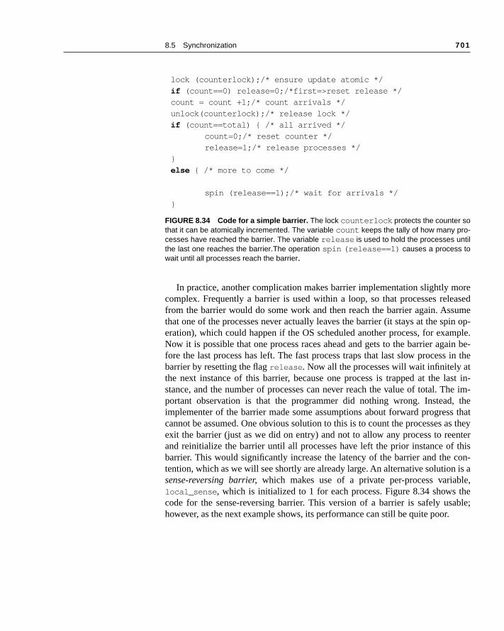
8.5 Synchronization 701
oreeasedumein op-
mple.ain be- in thetast in-he im- thes thats they
enter thiscon- is ale,theable;
In practice, another complication makes barrier implementation slightly mcomplex. Frequently a barrier is used within a loop, so that processes relfrom the barrier would do some work and then reach the barrier again. Assthat one of the processes never actually leaves the barrier (it stays at the speration), which could happen if the OS scheduled another process, for exaNow it is possible that one process races ahead and gets to the barrier agfore the last process has left. The fast process traps that last slow processbarrier by resetting the flag release . Now all the processes will wait infinitely athe next instance of this barrier, because one process is trapped at the lstance, and the number of processes can never reach the value of total. Tportant observation is that the programmer did nothing wrong. Instead,implementer of the barrier made some assumptions about forward progrescannot be assumed. One obvious solution to this is to count the processes aexit the barrier (just as we did on entry) and not to allow any process to reand reinitialize the barrier until all processes have left the prior instance ofbarrier. This would significantly increase the latency of the barrier and the tention, which as we will see shortly are already large. An alternative solutionsense-reversing barrier, which makes use of a private per-process variablocal_sense , which is initialized to 1 for each process. Figure 8.34 shows code for the sense-reversing barrier. This version of a barrier is safely ushowever, as the next example shows, its performance can still be quite poor.
lock (counterlock);/* ensure update atomic */
if (count==0) release=0;/*first=>reset release */
count = count +1;/* count arrivals */
unlock(counterlock);/* release lock */
if (count==total) { /* all arrived */
count=0;/* reset counter */
release=1;/* release processes */
}
else { /* more to come */
spin (release==1);/* wait for arrivals */
}
FIGURE 8.34 Code for a simple barrier. The lock counterlock protects the counter sothat it can be atomically incremented. The variable count keeps the tally of how many pro-cesses have reached the barrier. The variable release is used to hold the processes untilthe last one reaches the barrier.The operation spin (release==1) causes a process towait until all processes reach the barrier.
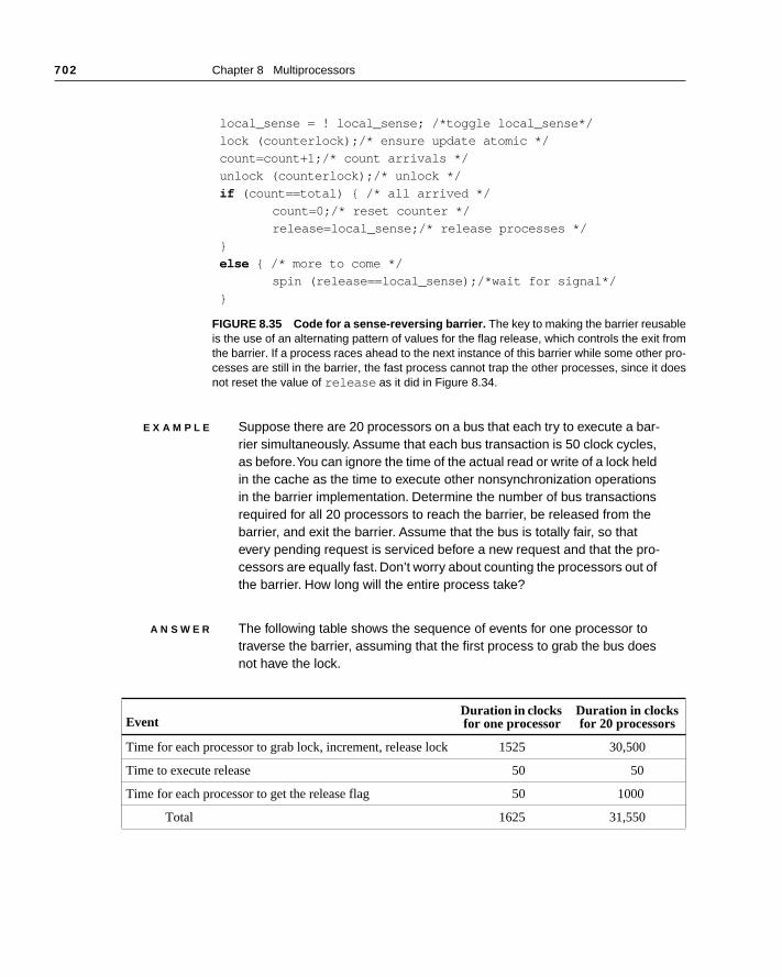
702 Chapter 8 Multiprocessors
E X A M P L E Suppose there are 20 processors on a bus that each try to execute a bar-rier simultaneously. Assume that each bus transaction is 50 clock cycles, as before. You can ignore the time of the actual read or write of a lock held in the cache as the time to execute other nonsynchronization operations in the barrier implementation. Determine the number of bus transactions required for all 20 processors to reach the barrier, be released from the barrier, and exit the barrier. Assume that the bus is totally fair, so that every pending request is serviced before a new request and that the pro-cessors are equally fast. Don’t worry about counting the processors out of the barrier. How long will the entire process take?
A N S W E R The following table shows the sequence of events for one processor to traverse the barrier, assuming that the first process to grab the bus does not have the lock.
local_sense = ! local_sense; /*toggle local_sense*/
lock (counterlock);/* ensure update atomic */
count=count+1;/* count arrivals */
unlock (counterlock);/* unlock */
if (count==total) { /* all arrived */
count=0;/* reset counter */
release=local_sense;/* release processes */
}
else { /* more to come */
spin (release==local_sense);/*wait for signal*/
}
FIGURE 8.35 Code for a sense-reversing barrier. The key to making the barrier reusableis the use of an alternating pattern of values for the flag release, which controls the exit fromthe barrier. If a process races ahead to the next instance of this barrier while some other pro-cesses are still in the barrier, the fast process cannot trap the other processes, since it doesnot reset the value of release as it did in Figure 8.34.
EventDuration in clocks for one processor
Duration in clocks for 20 processors
Time for each processor to grab lock, increment, release lock 1525 30,500
Time to execute release 50 50
Time for each processor to get the release flag 50 1000
Total 1625 31,550
8.5 Synchronization 703
be asses.t, wet is,tion.eadvari-f thee, it
ouldad asin the
pro-blemte theandthen itoper-zationuld beer the
un-tion is the two.
on-artifi-ying. Theer the
Our barrier operation takes a little longer than the 20-processor lock-unlock sequence we considered earlier. The total number of bus trans-actions is about 440. ■
As we can see from these examples, synchronization performance canreal bottleneck when there is substantial contention among multiple proceWhen there is little contention and synchronization operations are infrequenare primarily concerned about the latency of a synchronization primitive—thahow long it takes an individual process to complete a synchronization operaOur basic spin-lock operation can do this in two bus cycles: one to initially rthe lock and one to write it. We could improve this to a single bus cycle by a ety of methods. For example, we could simply spin on the swap operation. Ilock were almost always free, this could be better, but if the lock were not frewould lead to lots of bus traffic, since each attempt to lock the variable wlead to a bus cycle. In practice, the latency of our spin lock is not quite as bwe have seen in this example, since the write miss for a data item present cache is treated as an upgrade and will be cheaper than a true read miss.
The more serious problem in these examples is the serialization of eachcess’s attempt to complete the synchronization. This serialization is a prowhen there is contention, because it greatly increases the time to complesynchronization operation. For example, if the time to complete all 20 lock unlock operations depended only on the latency in the uncontended case, would take 2000 rather than 40,000 cycles to complete the synchronization ations. The use of a bus interconnect exacerbates this problem, but serialicould be just as serious in a directory-based machine, where the latency wolarge. The next section presents some solutions that are useful when eithcontention is high or the processor count is large.
Synchronization Mechanisms for Larger-Scale Machines
What we would like are synchronization mechanisms that have low latency incontended cases and that minimize serialization in the case where contensignificant. We begin by showing how software implementations can improveperformance of locks and barriers when contention is high; we then explorebasic hardware primitives that reduce serialization while keeping latency low
Software ImplementationsThe major difficulty with our spin-lock implementation is the delay due to ctention when many processes are spinning on the lock. One solution is to cially delay processes when they fail to acquire the lock. This is done by delaattempts to reacquire the lock whenever the store-conditional operation failsbest performance is obtained by increasing the delay exponentially whenev

704 Chapter 8 Multiprocessors
forks andtencyat if their
resultsses
howwareercise for
ause it much. We
an be leave
attempt to acquire the lock fails. Figure 8.36 shows how a spin lock with expo-nential back-off is implemented. Exponential back-off is a common techniquereducing contention in shared resources, including access to shared networbuses (see section 7.7). This implementation still attempts to preserve low lawhen contention is small by not delaying the initial spin loop. The result is thmany processes are waiting, the back-off does not affect the processes onfirst attempt to acquire the lock. We could also delay that process, but the would be poorer performance when the lock was in use by only two proceand the first one happened to find it locked.
Another technique for implementing locks is to use queuing locks. We show this works in the next section using a hardware implementation, but softimplementations using arrays can achieve most of the same benefits (see Ex8.24). Before we look at hardware primitives, let’s look at a better mechanismbarriers.
Our barrier implementation suffers from contention both during the gatherstage, when we must atomically update the count, and at the release stage, whenall the processes must read the release flag. The former is more serious becrequires exclusive access to the synchronization variable and thus createsmore serialization; in comparison, the latter generates only read contentioncan reduce the contention by using a combining tree, a structure where multiplerequests are locally combined in tree fashion. The same combining tree cused to implement the release process, reducing the contention there; wethe last step for the Exercises.
LI R3,#1 ;R3 = initial delay
lockit: LL R2,0(R1) ;load linked
BNEZ R2,lockit ;not available-spin
ADDI R2,R2,#1 ;get locked value
SC R2,0(R1) ;store conditional
BNEZ R2,gotit ;branch if store succeeds
SLL R3,R3,#1 ;increase delay by factor of 2
PAUSE R3 ;delays by value in R3
J lockit
gotit: use data protected by lock
FIGURE 8.36 A spin lock with exponential back-off. When the store conditional fails, theprocess delays itself by the value in R3. The delay can be implemented by decrementing R3until it reaches 0. The exact timing of the delay is machine dependent, although it should startwith a value that is approximately the time to perform the critical section and release the lock.The statement pause R3 should cause a delay of R3 of these time units. The value in R3 isincreased by a factor of 2 every time the store conditional fails, which causes the process towait twice as long before trying to acquire the lock again.
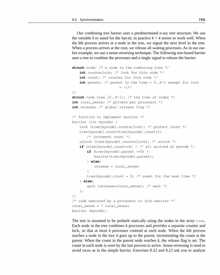
8.5 Synchronization 705
tree.ur ear-arrierr.
and
at the
sed toalyze
Our combining tree barrier uses a predetermined n-ary tree structure. We usethe variable k to stand for the fan-in; in practice k = 4 seems to work well. Whenthe kth process arrives at a node in the tree, we signal the next level in theWhen a process arrives at the root, we release all waiting processes. As in olier example, we use a sense-reversing technique. The following tree-based buses a tree to combine the processes and a single signal to release the barrie
struct node{ /* a node in the combining tree */
int counterlock; /* lock for this node */
int count; /* counter for this node */
int parent; /* parent in the tree = 0..P–1 except for root
= –1*/
};
struct node tree [0..P–1]; /* the tree of nodes */
int local_sense; /* private per processor */
int release; /* global release flag */
/* function to implement barrier */
barrier (int mynode) {
lock (tree[mynode].counterlock); /* protect count */
tree[mynode].count=tree[mynode].count+1;
/* increment count */
unlock (tree[mynode].counterlock); /* unlock */
if (tree[mynode].count==k) { /* all arrived at mynode */
if (tree[mynode].parent >=0) {
barrier(tree[mynode].parent);
} else {
release = local_sense;
}
tree[mynode].count = 0; /* reset for the next time */
} else {
spin (release==local_sense); /* wait */
};
};
/* code executed by a processor to join barrier */
local_sense = ! local_sense;
barrier (mynode);
The tree is assumed to be prebuilt statically using the nodes in the array tree .Each node in the tree combines k processes and provides a separate counter lock, so that at most k processes contend at each node. When the kth processreaches a node in the tree it goes up to the parent, incrementing the countparent. When the count in the parent node reaches k, the release flag is set. Thecount in each node is reset by the last process to arrive. Sense-reversing is uavoid races as in the simple barrier. Exercises 8.22 and 8.23 ask you to an

706 Chapter 8 Multiprocessors
PPs, but
firster ofs. Indenti-scal-
eseasedroces-ch of
and-ingf the
This
array eitherwhere a soft-essorlock
missory
k istrol-ds the
ns on.he listected fetch
the time for the combining barrier versus the noncombining version. Some M(e.g., the T3D and CM-5) have also included hardware support for barrierswhether such facilities will be included in future machines is unclear.
Hardware Primitives In this section we look at two hardware synchronization primitives. The primitive deals with locks, while the second is useful for barriers and a numbother user-level operations that require counting or supplying distinct indiceboth cases we can create a hardware primitive where latency is essentially ical to our earlier version, but with much less serialization, leading to better ing when there is contention.
The major problem with our original lock implementation is that it introduca large amount of unneeded contention. For example, when the lock is relall processors generate both a read and a write miss, although at most one psor can successfully get the lock in the unlocked state. This happens on eathe 20 lock/unlock sequences. We can improve this situation by explicitly hing the lock from one waiting processor to the next. Rather than simply allowall processors to compete every time the lock is released, we keep a list owaiting processors and hand the lock to one explicitly, when its turn comes.sort of mechanism has been called a queuing lock. Queuing locks can be imple-mented either in hardware, which we describe here, or in software using an to keep track of the waiting processes. The basic concepts are the same incase. Our hardware implementation assumes a directory-based machine the individual processor caches are addressable. In a bus-based machine,ware implementation would be more appropriate and would have each procusing a different address for the lock, permitting the explicit transfer of the from one process to another.
How does a queuing lock work? On the first miss to the lock variable, the is sent to a synchronization controller, which may be integrated with the memcontroller (in a bus-based system) or with the directory controller. If the locfree, it is simply returned to the processor. If the lock is unavailable, the conler creates a record of the node’s request (such as a bit in a vector) and senprocessor back a locked value for the variable, which the processor then spiWhen the lock is freed, the controller selects a processor to go ahead from tof waiting processors. It can then either update the lock variable in the selprocessor’s cache or invalidate the copy, causing the processor to miss andan available copy of the lock.
E X A M P L E How many bus transaction and how long does it take to have 20 proces-sors lock and unlock the variable using a queuing lock that updates the lock on a miss? Make the other assumptions about the system the same as before.
8.5 Synchronization 707
apa-o werovideented
to the and
pared beenor.
pera-uces seri-singing
incre-can
ode-
A N S W E R Each processor misses once on the lock initially and once to free the lock, so it takes only 40 bus cycles. The first 20 initial misses take 1000 cycles, followed by a 50-cycle delay for each of the 20 releases. This is a total of 2050 cycles—significantly better than the case with conventional coher-ence-based spin locks. ■
There are a couple of key insights in implementing such a queuing lock cbility. First, we need to be able to distinguish the initial access to the lock, scan perform the queuing operation, and also the lock release, so we can pthe lock to another processor. The queue of waiting processes can be implemby a variety of mechanisms. In a directory-based machine, this queue is akin sharing set, and similar hardware can be used to implement the directoryqueuing lock operations. One complication is that the hardware must be preto reclaim such locks, since the process that requested the lock may havecontext-switched and may not even be scheduled again on the same process
Queuing locks can be used to improve the performance of our barrier otion (see Exercise 8.15). Alternatively, we can introduce a primitive that redthe amount of time needed to increment the barrier count, thus reducing thealization at this bottleneck, which should yield comparable performance to uqueuing locks. One primitive that has been introduced for this and for buildother synchronization operations is fetch-and-increment, which atomically fetch-es a variable and increments its value. The returned value can be either themented value or the fetched value. Using fetch-and-increment we dramatically improve our barrier implementation, compared to the simple csensing barrier.
E X A M P L E Write the code for the barrier using fetch-and-increment. Making the same assumptions as in our earlier example and also assuming that a fetch-and-increment operation takes 50 clock cycles, determine the time for 20 processors to traverse the barrier. How many bus cycles are required?
A N S W E R Figure 8.37 shows the code for the barrier. This implementation requires 20 fetch-and-increment operations and 20 cache misses for the release operation. This is a total time of 2000 cycles and 40 bus/interconnect op-erations versus an earlier implementation that took over 15 times longer and 10 times more bus operations to complete the barrier. Of course, fetch-and-increment can also be used in implementing the combining tree barrier, reducing the serialization at each node in the tree.
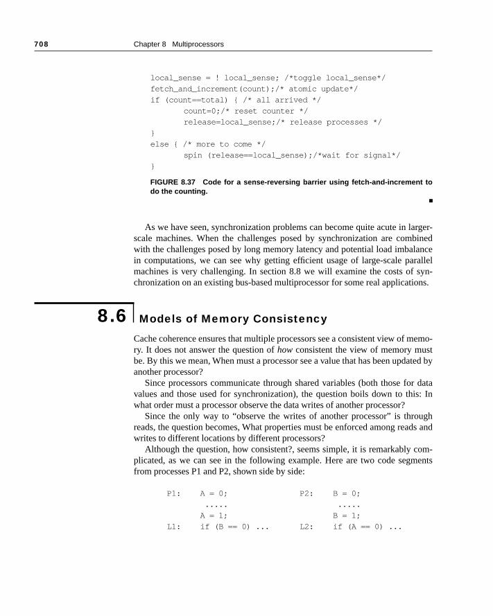
708 Chapter 8 Multiprocessors
arger-binedancerallelsyn-ons.
memo-tated by
r datais: In
ughds and
om-ents
■
As we have seen, synchronization problems can become quite acute in lscale machines. When the challenges posed by synchronization are comwith the challenges posed by long memory latency and potential load imbalin computations, we can see why getting efficient usage of large-scale pamachines is very challenging. In section 8.8 we will examine the costs of chronization on an existing bus-based multiprocessor for some real applicati
Cache coherence ensures that multiple processors see a consistent view of ry. It does not answer the question of how consistent the view of memory musbe. By this we mean, When must a processor see a value that has been updanother processor?
Since processors communicate through shared variables (both those fovalues and those used for synchronization), the question boils down to thwhat order must a processor observe the data writes of another processor?
Since the only way to “observe the writes of another processor” is throreads, the question becomes, What properties must be enforced among reawrites to different locations by different processors?
Although the question, how consistent?, seems simple, it is remarkably cplicated, as we can see in the following example. Here are two code segmfrom processes P1 and P2, shown side by side:
P1: A = 0; P2: B = 0;
..... .....
A = 1; B = 1;
L1: if (B == 0) ... L2: if (A == 0) ...
local_sense = ! local_sense; /*toggle local_sense*/
fetch_and_increment(count);/* atomic update*/
if (count==total) { /* all arrived */
count=0;/* reset counter */
release=local_sense;/* release processes */
}
else { /* more to come */
spin (release==local_sense);/*wait for signal*/
}
FIGURE 8.37 Code for a sense-reversing barrier using fetch-and-increment todo the counting.
8.6 Models of Memory Consistency
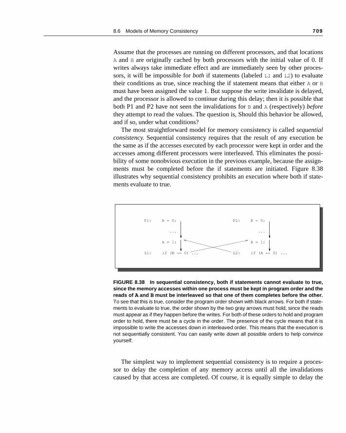
8.6 Models of Memory Consistency 709
ations. Ifoces-
layed, that
wed,
n be and thepossi-sign-8.38tate-
ces-ionsay the
Assume that the processes are running on different processors, and that locA and B are originally cached by both processors with the initial value of 0writes always take immediate effect and are immediately seen by other prsors, it will be impossible for both if statements (labeled L1 and L2) to evaluatetheir conditions as true, since reaching the if statement means that either A or Bmust have been assigned the value 1. But suppose the write invalidate is deand the processor is allowed to continue during this delay; then it is possibleboth P1 and P2 have not seen the invalidations for B and A (respectively) beforethey attempt to read the values. The question is, Should this behavior be alloand if so, under what conditions?
The most straightforward model for memory consistency is called sequentialconsistency. Sequential consistency requires that the result of any executiothe same as if the accesses executed by each processor were kept in orderaccesses among different processors were interleaved. This eliminates the bility of some nonobvious execution in the previous example, because the asments must be completed before the if statements are initiated. Figure illustrates why sequential consistency prohibits an execution where both if sments evaluate to true.
The simplest way to implement sequential consistency is to require a prosor to delay the completion of any memory access until all the invalidatcaused by that access are completed. Of course, it is equally simple to del
FIGURE 8.38 In sequential consistency, both if statements cannot evaluate to true,since the memory accesses within one process must be kept in program order and thereads of A and B must be interleaved so that one of them completes before the other.To see that this is true, consider the program order shown with black arrows. For both if state-ments to evaluate to true, the order shown by the two gray arrows must hold, since the readsmust appear as if they happen before the writes. For both of these orders to hold and programorder to hold, there must be a cycle in the order. The presence of the cycle means that it isimpossible to write the accesses down in interleaved order. This means that the execution isnot sequentially consistent. You can easily write down all possible orders to help convinceyourself.
P1:
L1:
A = 0;
...
A = 1;
if (B == 0) ...
P2:
L2:
B = 0;
...
B = 1;
if (A == 0) ...

710 Chapter 8 Multiprocessors
morys that, we-plyntialntial long
mem-ffecttrictive
tage,Theet al-t al-s ared by
next memory access until the previous one is completed. Remember that meconsistency involves operations among different variables: the two accessemust be ordered are actually to different memory locations. In our examplemust delay the read of A or B (A==0 or B==0) until the previous write has completed (B=1 or A=1). Under sequential consistency, we cannot, for example, simplace the write in a write buffer and continue with the read. Although sequeconsistency presents a simple programming paradigm, it reduces poteperformance, especially in a machine with a large number of processors, orinterconnect delays, as we can see in the following Example.
E X A M P L E Suppose we have a processor where a write miss takes 40 cycles to es-tablish ownership, 10 cycles to issue each invalidate after ownership is established, and 50 cycles for an invalidate to complete and be acknowl-edged once it is issued. Assuming that four other processors share a cache block, how long does a write miss stall the writing processor if the processor is sequentially consistent? Assume that the invalidates must be explicitly acknowledged before the directory controller knows they are completed. Suppose we could continue executing after obtaining owner-ship for the write miss without waiting for the invalidates; how long would the write take?
A N S W E R When we wait for invalidates, each write takes the sum of the ownership time plus the time to complete the invalidates. Since the invalidates can overlap, we need only worry about the last one, which starts 10 + 10 + 10 + 10 = 40 cycles after ownership is established. Hence the total time is 40 + 40 + 50 = 130 cycles. In comparison, the ownership time is only 40 cycles. With appropriate write-buffer implementations it is even possible to continue before ownership is established. ■
To provide better performance, designers have developed less restrictive ory consistency models that allow for faster hardware. Such models do ahow the programmer sees the machine, so before we discuss these less resmodels, let’s look at what the programmer expects.
The Programmer’s View
Although the sequential consistency model has a performance disadvanfrom the viewpoint of the programmer it has the advantage of simplicity. challenge is to develop a programming model that is simple to explain and ylows a high performance implementation. One such programming model thalows us to have a more efficient implementation is to assume that programsynchronized. A program is synchronized if all access to shared data is ordere
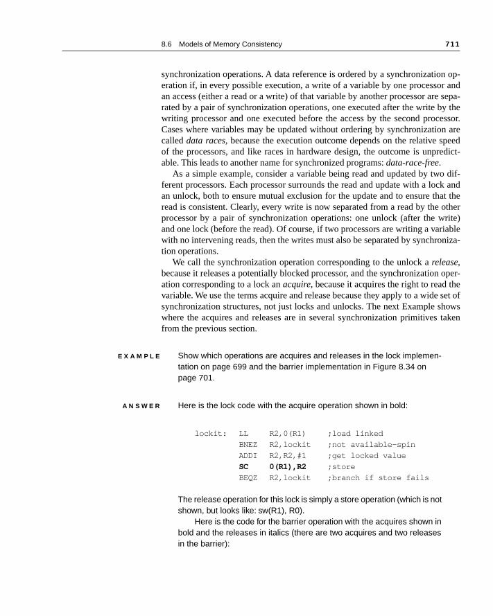
8.6 Models of Memory Consistency 711
n op-r and sepa-y thecessor.n arepeededict-
o dif-ck andat theotherrite)iableniza-
oper-e set of
howstaken
synchronization operations. A data reference is ordered by a synchronizatioeration if, in every possible execution, a write of a variable by one processoan access (either a read or a write) of that variable by another processor arerated by a pair of synchronization operations, one executed after the write bwriting processor and one executed before the access by the second proCases where variables may be updated without ordering by synchronizatiocalled data races, because the execution outcome depends on the relative sof the processors, and like races in hardware design, the outcome is unprable. This leads to another name for synchronized programs: data-race-free.
As a simple example, consider a variable being read and updated by twferent processors. Each processor surrounds the read and update with a loan unlock, both to ensure mutual exclusion for the update and to ensure thread is consistent. Clearly, every write is now separated from a read by the processor by a pair of synchronization operations: one unlock (after the wand one lock (before the read). Of course, if two processors are writing a varwith no intervening reads, then the writes must also be separated by synchrotion operations.
We call the synchronization operation corresponding to the unlock a release,because it releases a potentially blocked processor, and the synchronizationation corresponding to a lock an acquire, because it acquires the right to read thvariable. We use the terms acquire and release because they apply to a widesynchronization structures, not just locks and unlocks. The next Example swhere the acquires and releases are in several synchronization primitives from the previous section.
E X A M P L E Show which operations are acquires and releases in the lock implemen-tation on page 699 and the barrier implementation in Figure 8.34 on page 701.
A N S W E R Here is the lock code with the acquire operation shown in bold:
lockit: LL R2,0(R1) ;load linked
BNEZ R2,lockit ;not available-spin
ADDI R2,R2,#1 ;get locked value
SC 0(R1),R2 ;store
BEQZ R2,lockit ;branch if store fails
The release operation for this lock is simply a store operation (which is not shown, but looks like: sw(R1), R0).
Here is the code for the barrier operation with the acquires shown in bold and the releases in italics (there are two acquires and two releases in the barrier):

712 Chapter 8 Multiprocessors
eleas-bysor con-
am is by syn-
. Thisd, thepeedaffectbout
rder-ely
rally,tead, cor-dard
■
We can now define when a program is synchronized using acquires and res. A program is synchronized if every execution sequence containing a write a processor and a subsequent access of the same data by another procestains the following sequence of events:
write (x)
...
release (s)
...
acquire (s)
...
access(x)
It is easy to see that if all such execution sequences look like this, the progrsynchronized in the sense that accesses to shared data are always orderedchronization and that data races are impossible.
It is a broadly accepted observation that most programs are synchronizedobservation is true primarily because if the accesses were unsynchronizebehavior of the program would be quite difficult to determine because the sof execution would determine which processor won a data race and thus the results of the program. Even with sequential consistency, reasoning asuch programs is very difficult. Programmers could attempt to guarantee oing by constructing their own synchronization mechanisms, but this is extremtricky, can lead to buggy programs, and may not be supported architectumeaning that they may not work in future generations of the machine. Insalmost all programmers will choose to use synchronization libraries that arerect and optimized for the machine and the type of synchronization. A stan
lock (counterlock) ;/* ensure update atomic */
if (count==0) release=0;/*first=>reset release */
count=count+1;/* count arrivals */
unlock(counterlock) ;/* release lock */
if (count==total) { /* all arrived */
count=0;/* reset counter */
release=1; /* release processes */
}
else{ /* more to come */
spin (release==1) ;/* wait for arrivals */
}
8.6 Models of Memory Consistency 713
n in in the
avoidory.rn anrrectshion,
ng of
thatcuted
com-
writeorder
s asbound-ence. that
Thusuntilated
ointarliest
nce.sses.d, so
e po-ces.inary
synchronization library can classify the operations used for synchronizatiothe library as releases or acquires, or sometimes as both, as, for example,case of a barrier.
The major use of unsynchronized accesses is in programs that want to synchronization cost and are willing to accept an inconsistent view of memFor example, in a stochastic program we may be willing to have a read retuold value of a data item, because the program will still converge on the coanswer. In such cases we still require the system to behave in a coherent fabut we do not need to rely on a well-defined consistency model.
Beyond the synchronization operations, we also need to define the orderimemory operations. There are two types of restrictions on memory orders: writefences and read fences. Fences are fixed points in a computation that ensure no read or write is moved across the fence. For example, a write fence exeby processor P ensures that
■ all writes by P that occur before P executed the write fence operation havepleted, and
■ no writes that occur after the fence in P are initiated before the fence.
In sequential consistency, all reads are read fences and all writes are fences. This limits the ability of the hardware to optimize accesses, since must be strictly maintained.
From a performance viewpoint, the processor would like to execute readearly as possible and complete writes as late as possible. Fences act as aries, forcing the processor to order reads and writes with respect to the fAlthough a write fence is a two-way blockade, it is most often used to ensurewrites have completed, since the processor wants to delay write completion.the typical effect of a write fence is to cause the program execution to stall all outstanding writes have completed, including the delivery of any associinvalidations.
A read fence is also a two-way blockade, marking the earliest or latest pthat a read may be executed. Most often a read fence is used to mark the epoint that a read may be executed.
A memory fence is an operation that acts as both a read and a write feMemory fences enforce ordering among the accesses of different proceWithin a single process we require that program order always be preservereads and writes of the same location cannot be interchanged.
The weaker consistency models discussed in the next section provide thtential for hiding read and write latency by defining fewer read and write fenIn particular, synchronization accesses act as the fences rather than ordaccesses.
714 Chapter 8 Multiprocessors
model thatpro-f re-
of a a se-on-traints
impli-s of
ons
to
to
r pro-dence, A se-nd islizesy bar-
uted
writelida-ed but
. In-lcribed,ta- be
Relaxed Models for Memory Consistency
Since most programs are synchronized and since a sequential consistency imposes major inefficiencies, we would like to define a more relaxed modelallows higher performance implementations and still preserves a simple gramming model for synchronized programs. In fact, there are a number olaxed models that all maintain the property that the execution semanticssynchronized program is the same under the model as it would be underquential consistency model. The relaxed models vary in how tightly they cstrain the set of possible execution sequences, and thus in how many consthey impose on the implementation.
To understand the variations among the relaxed models and the possible cations for an implementation, it is simplest if we define the models in termwhat orderings among reads and writes performed by a single processor are pre-served by each model. There are four such orderings:
1. R → R: a read followed by a read.
2. R → W: a read followed by a write, which is always preserved if the operatiare to the same address, since this is an antidependence.
3. W → W: a write followed by a write, which is always preserved if they arethe same address, since this is an output dependence.
4. W → R: a write followed by a read, which is always preserved if they arethe same address, since this is a true dependence.
If there is a dependence between the read and the write, then uniprocessogram semantics demand that the operations be ordered. If there is no depenthe memory consistency model determines what orders must be preserved.quential consistency model requires that all four orderings be preserved athus equivalent to assuming a single centralized memory module that seriaall processor operations, or to assuming that all reads and writes are memorriers.
When an order is relaxed, it simply means that we allow an operation execlater by the processor to complete first. For example, relaxing the ordering W→Rmeans that we allow a read that is later than a write to complete before thehas completed. Remember that a write does not complete until all its invations complete, so letting the read occur after the write miss has been handlbefore the invalidations are done does not preserve the ordering.
A consistency model does not, in reality, restrict the ordering of eventsstead, it says what possible orderings can be observed. For example, in sequentiaconsistency, the system must appear to preserve the four orderings just desalthough in practice it can allow reordering. This subtlety allows implementions to use tricks that reorder events without allowing the reordering to
8.6 Models of Memory Consistency 715
le, al-ted, earli- pre-y to
syn-. When syn-odels,
cess-plestIf weh the
other
read
ss-d be-
all the of a
lica-chro-
ead isttern
s
d thisum-
show
by
orleteation
g:
observed. Under sequential consistency an implementation can, for examplow a processor, P, to initiate another write before an earlier write is compleas long as P does not allow the value of the later write to be seen before theer write has completed. For simplicity, we discuss what orderings must beserved, with the understanding that the implementation has the flexibilitpreserve fewer orderings if only the preserved orderings are visible.
The consistency model must also define the orderings imposed betweenchronization variable accesses, which act as fences, and all other accessesa machine implements sequential consistency, all reads and writes, includingchronization accesses, are fences and are thus kept in order. For weaker mwe need to specify the ordering restrictions imposed by synchronization aces, as well as the ordering restrictions involving ordinary variables. The simordering restriction is that every synchronization access is a memory fence. let S stand for a synchronization variable access, we could also write this witordering notation just shown as S→W, S→R, W→S, and R→S. Remember that asynchronization access is also an R or a W and its ordering is affected by synchronization accesses, which means there is an implied ordering S→S.
The first model we examine relaxes the ordering between a write and a(to a different address), eliminating the order W→R; this model was first used inthe IBM 370 architecture. Such models allow the buffering of writes with bypaing by reads, which occurs whenever the processor allows a read to proceefore it guarantees that an earlier write by that processor has been seen by other processors. This model allows a machine to hide some of the latencywrite operation. Furthermore, by relaxing only this one ordering, many apptions, even those that are unsynchronized, operate correctly, although a synnization operation is necessary to ensure that a write completes before a rdone. If a synchronization operation is executed before the read (i.e. a paW...S...R), then the orderings W→S and S→R ensure that the write completebefore the read. Processor consistency and total store ordering (TSO) have beenused as names for this model, and many machines have implicitly selectemodel. This model is equivalent to making the writes be write fences. We smarize all the models, showing the orderings imposed, in Figure 8.39 and an example in Figure 8.40.
If we also allow nonconflicting writes to potentially complete out of order, relaxing the W →W ordering, we arrive at a model that has been called partialstore ordering (PSO). From an implementation viewpoint, it allows pipelining overlapping of write operations, rather than forcing one operation to compbefore another. A write operation need only cause a stall when a synchronizoperation, which causes a write fence, is encountered.
The third major class of relaxed models eliminates the R → R and R → W or-derings, in addition to the other two orders. This model, which is called weak or-dering, does not preserve ordering among references, except for the followin
716 Chapter 8 Multiprocessors
ed in
rites
cre-
has or-
Eventainsthe Rfor theal, theten-
Thisa-
Sms ann mustquire.
thatread ors that in ringsgs tosessses.nder
easily con-ire orically barri-alent to
■ A read or write is completed before any synchronization operation executprogram order by the processor after the read or write.
■ A synchronization operation is always completed before any reads or wthat occur in program order after the operation.
As Figure 8.39 shows, the only orderings imposed in weak order are thoseated by synchronization operations. Although we have eliminated the R → R andR → W orderings, the processor can only take advantage of this if it nonblocking reads. Otherwise the processor implicitly implements these twoders, since no further instructions can be executed until the R is completed.with nonblocking reads, the processor may be limited in the advantage it obfrom relaxing the read orderings, since the primary advantage occurs when causes a cache miss and the processor is unlikely to be able to keep busy tens to hundreds of cycles that handling the cache miss may take. In genermajor advantage of all weaker consistency models comes in hiding write lacies rather than read latencies.
A more relaxed model can be obtained by extending weak ordering. model, called release consistency, distinguishes between synchronization opertions that are used to acquire access to a shared variable (denoted SA) and thosethat release an object to allow another processor to acquire access (denotedR).Release consistency is based on the observation that in synchronized prograacquire operation must precede a use of shared data, and a release operatiofollow any updates to shared data and also precede the time of the next acThis allows us to slightly relax the ordering by observing that a read or writeprecedes an acquire need not complete before the acquire, and also that a write that follows a release need not wait for the release. Thus the orderingare preserved involve only SA and SR , as shown in Figure 8.39; as the exampleFigure 8.40 shows, this model imposes the fewest orders of the five models.
To compare release consistency to weak ordering, consider what ordewould be needed for weak ordering, if we decompose each S in the orderinSA and SR. This would lead to eight orderings involving synchronization accesand ordinary accesses plus four orderings involving only synchronization acceWith such a description, we can see that four of the orderings required uweak ordering are not imposed under release consistency: W → SA, R→ SA,SR → R, and SR → W.
Release consistency provides one of the least restrictive models that is checkable, and ensures that synchronized programs will see a sequentiallysistent execution. While most synchronization operations are either an acqua release (an acquire normally reads a synchronization variable and atomupdates it, while a release usually just writes it), some operations, such as aer, act as both an acquire and a release and cause the ordering to be equivweak ordering.
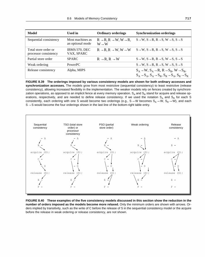
8.6 Models of Memory Consistency 717
Model Used in Ordinary orderings Synchronization orderings
Sequential consistency Most machines as an optional mode
R →R, R →W, W→R, W→W
S→W, S→R, R→S, W→S, S→S
Total store order or processor consistency
IBMS/370, DEC VAX, SPARC
R →R, R →W, W→W S→W, S→R, R→S, W→S, S→S
Partial store order SPARC R →R, R →W S→W, S→R, R→S, W→S, S→S
Weak ordering PowerPC S→W, S→R, R→S, W→S, S→S
Release consistency Alpha, MIPS SA→W, SA→R, R→SR, W→SR,SA→SA, SA→SR, SR→SA, SR→SR
FIGURE 8.39 The orderings imposed by various consistency models are shown for both ordinary accesses andsynchronization accesses. The models grow from most restrictive (sequential consistency) to least restrictive (releaseconsistency), allowing increased flexibility in the implementation. The weaker models rely on fences created by synchroni-zation operations, as opposed to an implicit fence at every memory operation. SA and SR stand for acquire and release op-erations, respectively, and are needed to define release consistency. If we used the notation SA and SR for each Sconsistently, each ordering with one S would become two orderings (e.g., S→W becomes SA→W, SR→W), and eachS→S would become the four orderings shown in the last line of the bottom-right table entry.
FIGURE 8.40 These examples of the five consistency models discussed in this section show the reduction in thenumber of orders imposed as the models become more relaxed. Only the minimum orders are shown with arrows. Or-ders implied by transitivity, such as the write of C before the release of S in the sequential consistency model or the acquirebefore the release in weak ordering or release consistency, are not shown.
= A
B =
acquire (S);
C =
= D
release (S);
E =
F =
Sequentialconsistency
= A
B =
acquire (S);
C =
= D
release (S);
E =
F =
TSO (total storeorder) or
processorconsistency
= A
B =
acquire (S);
C =
= D
release (S);
E =
F =
PSO (partialstore order)
= A
B =
acquire (S);
C =
= D
release (S);
E =
F =
Weak ordering Releaseconsistency
= A
B =
acquire (S);
C =
= D
release (S);
E =
F =
718 Chapter 8 Multiprocessors
leaseniza-s be
, wer syn-tively
ple,er or-
onalectmoryssor,tely,ding
con- con-
tion is to a
eadeter- readt twoalita-is that
f the also.
allowrites.r asrting
data con-r thedingunt
It is also possible to consider even weaker orderings. For example, in reconsistency we do not associate memory locations with particular synchrotion variables. If we required that the same synchronization variable, V, alwayacquired before accessing a particular memory location, M, for examplecould relax the ordering of access to M and acquires and releases of all othechronization variables other than V. The orderings discussed so far are relastraightforward to implement. Weaker orderings, such as the previous examare harder to implement, and it is unclear whether the advantages of weakderings would justify their implementation.
Implementation of Relaxed Models
Relaxed models of consistency can usually be implemented with little additihardware. Most of the complexity lies in implementing memory or interconnsystems that can take advantage of a relaxed model. For example, if the meor interconnect does not allow multiple outstanding accesses from a procethen the benefits of the more ambitious relaxed models will be small. Fortunamost of the benefit can be obtained by having a small number of outstanwrites and one outstanding read.
In this section we describe straightforward implementations of processor sistency and release consistency. Our directory protocols already satisfy thestraints of sequential consistency, since the processor stalls until an operacomplete and the directory first invalidates all sharers before respondingwrite miss.
Processor consistency (or TSO) is typically implemented by allowing rmisses to bypass pending writes. A write buffer that can support a check to dmine whether any pending write in the buffer is to the same address as amiss, together with a memory and interconnection system that can supporoutstanding references per node, is sufficient to implement this scheme. Qutively, the advantage of processor consistency over sequential consistency it allows the latency of write misses to be hidden.
Release consistency allows additional write latency to be hidden, and iprocessor supports nonblocking reads, allows the read latency to be hiddenTo allow write latency to be hidden as much as possible, the processor mustmultiple outstanding writes and allow read misses to bypass outstanding wTo maximize performance, writes should complete and clear the write buffeearly as possible, which allows any dependent reads to go forward. Suppoearly completion of writes requires allowing a write to complete as soon asare available and before all pending invalidations are completed (since oursistency model allows this). To implement this scheme, either the directory ooriginal requester can keep track of the invalidation count for each outstanwrite. After each invalidation is acknowledged, the pending invalidation co
8.6 Models of Memory Consistency 719
l out-mplyse isdingat it
eads;s arepen-n of per-oces-hidecutes cy-
on, itationmi-
cles,ited,
tency
both per-envi-rties:
r dy-
ard-
for that write is decreased. We must ensure that all pending invalidates to alstanding writes complete before we allow a release to complete, so we sicheck the pending invalidation counts on any outstanding write when a releaexecuted. The release is held up until all such invalidations for all outstanwrites complete. In practice, we limit the number of outstanding writes, so this easy to track the writes and pending invalidates.
To hide read latency we must have a machine that has nonblocking rotherwise, when the processor blocks, little progress will be made. If readnonblocking we can simply allow them to execute, knowing that the data dedences will preserve correct execution. It is unlikely, however, that the additiononblocking reads to a relaxed consistency model will substantially enhanceformance. The limited gain occurs because the read miss times in a multiprsor are likely to be large and the processor can provide only limited ability to this latency. For example, if the reads are nonblocking but the processor exein order, then the processor will almost certainly block for the read after a fewcles. If the processor supports nonblocking reads and out-of-order executiwill block as soon as any of its buffers, such as the reorder buffer or reservstations, are full. (See Chapter 4 for a discussion of full buffer stalls in dynacally scheduled machines.) This is likely to happen in at most tens of cywhile a miss may cost a hundred cycles. Thus, although the gain may be limthere is a positive synergy between nonblocking loads and relaxed consismodels.
Performance of Relaxed Models
The performance potential of a more relaxed consistency model depends onthe capabilities of the machine and the particular application. To examine theformance of a memory consistency model, we must first define a hardware ronment. The hardware configurations we consider have the following prope
■ The pipeline issues one instruction per clock cycle and is either statically onamically scheduled. All functional unit latencies are one cycle.
■ Cache misses take 50 clock cycles.
■ The CPU includes a write buffer of depth 16.
■ The caches are 64 KB and have 16-byte blocks.
To give a flavor of the tradeoffs and performance potential with different hware capabilities, we consider four hardware models:
1. SSBR (statically scheduled with blocking reads)—The processor is staticallyscheduled and reads that miss in the cache immediately block.
720 Chapter 8 Multiprocessors
do
out-s.
out-rge
ramerenterfor-enta-ancer miss Fig-ld in-ing toratetions.
nsis-nd al-ationram-pro-the
as oftesttim- ma-moteand ass non-ing a
high
2. SS (statically scheduled)—The processor is statically scheduled but readsnot cause the processor to block until the result is used.
3. DS16 (dynamically scheduled with a 16-entry reorder buffer)—The proces-sor is dynamically scheduled and has a reorder buffer that allows up to 16standing instructions of any type, including 16 memory access instruction
4. DS64 (dynamically scheduled with a 64-entry reorder buffer)—The proces-sor is dynamically scheduled and has a reorder buffer that allows up to 64standing instructions of any type. This reorder buffer is potentially laenough to hide the total cache miss latency of 50 cycles.
Figure 8.41 shows the relative performance for two of the parallel progbenchmarks, LU and Ocean, for these four hardware models and for two diffconsistency models: total store order (TSO) and release consistency. The pmance is shown relative to the performance under a straightforward implemtion of sequential consistency. Relaxed models offer a much larger performgain on Ocean than on LU. This is simply because Ocean has a much higherate and has a significant fraction of write misses. In interpreting the data inure 8.41, remember that the caches are fairly small. Most designers woucrease the cache size before including nonblocking reads or even beginnthink about dynamic scheduling. This would dramatically reduce the miss and the possible advantage from the relaxed model at least for these applica
Final Remarks on Consistency Models
At the present time, most machines being built support some sort of weak cotency model, varying from processor consistency to release consistency, amost all also support sequential consistency as an option. Since synchronizis highly machine specific and error prone, the expectation is that most progmers will use standard synchronization libraries and will write synchronized grams, making the choice of a weak consistency model invisible to programmer and yielding higher performance. Yet to be developed are idehow to deal with nondeterministic programs that do not rely on getting the lavalues. One possibility is that programmers will not need to rely at all on the ing of updates to variables in such programs; the other possibility is thatchine-specific models of update behavior will be needed and used. As reaccess latencies continue to increase relative to processor performance, features that increase the potential advantage of relaxed models, such ablocking caches, are included in more processors, the importance of choosconsistency model that delivers both a convenient programming model andperformance will increase.
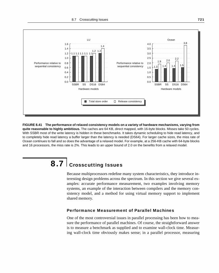
8.7 Crosscutting Issues 721
ce in-ral ex-mory con-ent
mea-swerasur-ring
Because multiprocessors redefine many system characteristics, they introduteresting design problems across the spectrum. In this section we give seveamples: accurate performance measurement, two examples involving mesystems, an example of the interaction between compilers and the memorysistency model, and a method for using virtual memory support to implemshared memory.
Performance Measurement of Parallel Machines
One of the most controversial issues in parallel processing has been how tosure the performance of parallel machines. Of course, the straightforward anis to measure a benchmark as supplied and to examine wall-clock time. Meing wall-clock time obviously makes sense; in a parallel processor, measu
FIGURE 8.41 The performance of relaxed consistency models on a variety of hardware mechanisms, varying fromquite reasonable to highly ambitious. The caches are 64 KB, direct mapped, with 16-byte blocks. Misses take 50 cycles.With SSBR most of the write latency is hidden in these benchmarks. It takes dynamic scheduling to hide read latency, andto completely hide read latency a buffer larger than the latency is needed (DS64). For larger cache sizes, the miss rate ofOcean continues to fall and so does the advantage of a relaxed model. For example, at a 256-KB cache with 64-byte blocksand 16 processors, the miss rate is 2%. This leads to an upper bound of 2.0 on the benefits from a relaxed model.
8.7 Crosscutting Issues
Performance relative tosequential consistency
0.0
0.6
0.4
0.2
SSBR SS DS16 DS64
Hardware models Hardware models
LU
1.6
0.8
1.4
1.2 1.1 1.1 1.1 1.1 1.11.2 1.2
1.4
1.0
Performance relative tosequential consistency
0.0
1.5
1.0
0.5
SSBR SS DS16 DS64
Ocean
4.0
2.0
3.5
3.0
1.3
1.9
1.4
2.0
1.4
2.2
1.5
3.8
2.5
Total store order Release consistency
722 Chapter 8 Multiprocessors
ailable
ma- per-ense toffects re-ill beup as
of thes. Thevoidnder-is dis-
markench-rob-ng thecalled
e theation
times
CPU time can be misleading because the processors may be idle but unavfor other uses.
Users and designers are often interested in knowing not just how well achine performs with a certain fixed number of processors, but also how theformance scales as more processors are added. In many cases, it makes sscale the application or benchmark, since if the benchmark is unscaled, earising from limited parallelism and increases in communication can lead tosults that are pessimistic when the expectation is that more processors wused to solve larger problems. Thus it is often useful to measure the speedprocessors are added both for a fixed-size problem and for a scaled versionproblem, providing an unscaled and a scaled version of the speedup curvechoice of how to measure the uniprocessor algorithm is also important to aanomalous results, since using the parallel version of the benchmark may ustate the uniprocessor performance and thus overstate the speedup. This cussed with an example in section 8.9.
Once we have decided to measure scaled speedup, the question is how to scalethe application. Let’s assume that we have determined that running a benchof size n on p processors makes sense. The question is how to scale the bmark to run on m × p processors. There are two obvious ways to scale the plem: keeping the amount of memory used per processor constant; and keepitotal execution time, assuming perfect speedup, constant. The first method, memory-constrained scaling, specifies running a problem of size m × n on m × pprocessors. The second method, called time-constrained scaling, requires that weknow the relationship between the running time and the problem size, sincformer is kept constant. For example, suppose the running time of the applicwith data size n on p processors is proportional to n2/p. Then with time-constrained scaling, the problem to run is the problem whose ideal runningon m × p processors is still n2/p. The problem with this ideal running time hasize .
E X A M P L E Suppose we have a problem whose execution time for a problem of size n is proportional to n3. Suppose the actual running time on a 10-processor machine is 1 hour. Under the time-constrained and memory-constrained scaling models, find the size of the problem to run and the effective run-ning time for a 100-processor machine.
A N S W E R For the time-constrained problem, the ideal running time is the same, 1 hour, so the problem size is . For memory-constrained scaling, the size of the problem is 10n and the ideal execution time is 103/10, or 100 hours! Since most users will be reluctant to run a problem on an order of magnitude more processors for 100 times longer, this size problem is probably unrealistic. ■
m n×
103 n×
8.7 Crosscutting Issues 723
pro-of theena,
hangeffect in- more, the
indi-of ther inl to
-
ds a-tors,a intionize.
ing thet onlyed as
he de-ucess. Inpactssor
de-e alsoheturec, as
In addition to the scaling methodology, there are questions as to how thegram should be scaled when increasing the problem size affects the quality result. Since many parallel programs are simulations of physical phenomchanging the problem size changes the quality of the result, and we must cthe application to deal with this effect. As a simple example, consider the eof time to convergence for solving a differential equation. This time typicallycreases as the problem size increases, since, for example, we often requireiterations for the larger problem. Thus when we increase the problem sizetotal running time may scale faster than the basic algorithmic scaling would cate. For example, suppose that the number of iterations grows as the log problem size. Then for a problem whose algorithmic running time is lineathe size of the problem, the effective running time actually grows proportionan log n. If we scaled from a problem of size m on 10 processors, purely algorithmic scaling would allow us to run a problem of size 10 m on 100 processors. Ac-counting for the increase in iterations means that a problem of size k × m, wherek log k = 10, will have the same running time on 100 processors. This yielscaling of 5.72 m, rather than 10 m. In practice, scaling to deal with error requires a good understanding of the application and may involve other facsuch as error tolerances (for example, it affects the cell-opening criteriBarnes-Hut). In turn, such effects often significantly affect the communicaor parallelism properties of the application as well as the choice of problem s
Scaled speedup is not the same as unscaled (or true) speedup; confustwo has led to erroneous claims. Scaled speedup has an important role, buwhen the scaling methodology is sound and the results are clearly reportusing a scaled version of the application.
Memory System Issues
As we have seen in this chapter, memory system issues are at the core of tsign of shared-memory multiprocessors. Indeed, multiprocessing introdmany new memory system complications that do not exist in uniprocessorthis section we look at two implementation issues that have a significant imon the design and implementation of a memory system in a multiprocecontext.
Inclusion and Its ImplementationMany multiprocessors use multilevel cache hierarchies to reduce both themand on the global interconnect and the latency of cache misses. If the cachprovides multilevel inclusion—every level of cache hierarchy is a subset of tlevel further away from the processor—then we can use the multilevel structo reduce the contention between coherence traffic and processor traffi
724 Chapter 8 Multiprocessors
the
ial.es aateted,
rent.rger
wantnclu- L1,le L1iss
led
lev-e thathes.n in-inclu-vels
explained earlier. Thus most multiprocessors with multilevel caches enforceinclusion property. This restriction is also called the subset property, becauseeach cache is a subset of the cache below it in the hierarchy.
At first glance, preserving the multilevel inclusion property seems trivConsider a two-level example: any miss in L1 either hits in L2 or generatmiss in L2, causing it to be brought into both L1 and L2. Likewise, any invalidthat hits in L2 must be sent to L1, where it will cause the block to be invalidaif it exists.
The catch is what happens when the block size of L1 and L2 are diffeChoosing different block sizes is quite reasonable, since L2 will be much laand have a much longer latency component in its miss penalty, and thus willto use a larger block size. What happens to our “automatic” enforcement of ision when the block sizes differ? A block in L2 represents multiple blocks inand a miss in L2 causes the replacement of data that is equivalent to multipblocks. For example, if the block size of L2 is four times that of L1, then a min L2 will replace the equivalent of four L1 blocks. Let’s consider a detaiexample.
E X A M P L E Assume that L2 has a block size four times that of L1. Show how a miss for an address that causes a replacement in L1 and L2 can lead to viola-tion of the inclusion property.
A N S W E R Assume that L1 and L2 are direct mapped and that the block size of L1 is b bytes and the block size of L2 is 4b bytes. Suppose L1 contains blocks with starting addresses x and x + b and that x mod 4b = 0, meaning that x also is the starting address of a block in L2. That single block in L2 con-tains the L1 blocks x, x + b, x + 2b, and x + 3b. Suppose the processor generates a reference to block y that maps to the block containing x in both caches and hence misses. Since L2 missed, it fetches 4b bytes and replaces the block containing x, x + b, x + 2b, and x + 3b, while L1 takes b bytes and replaces the block containing x. Since L1 still contains x + b, but L2 does not, the inclusion property no longer holds. ■
To maintain inclusion with multiple block sizes, we must probe the higher els of the hierarchy when a replacement is done at the lower level to ensurany words replaced in the lower level are invalidated in the higher-level cacMost systems chose this solution rather than the alternative of not relying oclusion and snooping the higher-level caches. In the Exercises we explore sion further and show that similar problems exist if the associativity of the leis different.
8.7 Crosscutting Issues 725
e then and
case.morerger,nding
tencyuires
ntinuershiper re-ge ofmicels to
ch-ipro-r 5 we pro-hout
thed val-
ction,r ther vari-s that most
t, a sincecoher-rties
egis-
e: a con-
e pro-e old
is in-h is
Nonblocking Caches and Latency Hiding We saw the idea of nonblocking or lockup-free caches in Chapter 5, wherconcept was used to reduce cache misses by overlapping them with executioby pipelining misses. There are additional benefits in the multiprocessor The first is that the miss penalties are likely to be larger, meaning there is latency to hide, and the opportunity for pipelining misses is also probably lasince the memory and interconnect system can often handle multiple outstamemory references.
A machine needs nonblocking caches to take advantage of weak consismodels. For example, to implement a model like processor consistency reqthat writes be nonblocking with respect to reads so that a processor can coeither immediately, by buffering the write, or as soon as it establishes owneof the block and updates the cache. Relaxed consistency models allow furthordering of misses, but nonblocking caches are needed to take full advantathis flexibility. With the more extensive use of nonblocking caches and dynascheduling, we can expect the potential benefits of relaxed consistency modincrease. Finally, nonblocking support is critical to implementing prefetching. Prefeting, which we also discussed in Chapter 5, is even more important in multcessors than in uniprocessors, due to longer memory latencies. In Chaptedescribed why it is important that prefetches not affect the semantics of thegram, since this allows them to be inserted anywhere in the program witchanging the results of the computation.
In a multiprocessor, maintaining the absence of any semantic impact fromuse of prefetches requires that prefetched data be kept coherent. A prefetcheue is kept coherent if, when the value is actually accessed by a load instruthe most recently written value is returned, even if that value was written afteprefetch. This is exactly the property that cache coherence gives us for otheables in memory. A prefetch that brings a data value closer, and guaranteeon the actual memory access to the data (a load of the prefetched value) therecent value of the data item is obtained, is called nonbinding, since the data val-ue is not bound to a local copy, which would be incoherent. By contrasprefetch that moves a data value into a general-purpose register is binding,the register value is a new variable, as opposed to a cache block, which is a ent copy of a variable. A nonbinding prefetch maintains the coherence propeof any other value in memory, while a binding prefetch appears more like a rter load, since it removes the data from the coherent address space.
Why is nonbinding prefetch critical? Consider a simple but typical exampldata value written by one processor and used by another. In this case, thesumer would like to prefetch the value as early as possible; but suppose thducing process is delayed for some reason. Then the prefetch may fetch thvalue of the data item. If the prefetch is nonbinding, the copy of the old data validated when the value is written, maintaining coherence. If the prefetc

726 Chapter 8 Multiprocessors
the needim to
oher-
-freecauses
since han-f the
sued a leadriteping
t thewaitallingpro-
theIn ex-nedd andht af-iza-
usuallyple,yn-rise.
orksta-echa-This
binding, however, then the old, incoherent value of the data is used byprefetching process. Because of the long memory latencies, a prefetch mayto be placed a hundred or more instructions earlier than the data use, if we ahide the entire latency. This makes the nonbinding property vital to ensure cent usage of the prefetch in multiprocessors.
Implementing prefetch requires the same sort of support that a lockupcache needs, since there are multiple outstanding memory accesses. This several complications:
1. A local node will need to keep track of the multiple outstanding accesses, the replies may return in a different order than they were sent. This can bedled by adding tags to the requests, or by incorporating the address omemory block in the reply.
2. Before issuing a request, the node must ensure that it has not already isrequest for the same block, since two requests for the same block couldto incorrect operation of the protocol. In particular, if the node issues a wmiss to a block, while it has such a write miss outstanding both our snooprotocol and directory protocol fail to operate properly.
3. Our implementation of the directory and snooping controllers assumes thaprocessor stalls on a miss. Stalling allows the cache controller to simply for a reply when it has generated a request. With a nonblocking cache, stis not possible and the actual implementation must deal with additional cessor requests.
Compiler Optimization and the Consistency Model
Another reason for defining a model for memory consistency is to specifyrange of legal compiler optimizations that can be performed on shared data. plicitly parallel programs, unless the synchronization points are clearly defiand the programs are synchronized, the compiler could not interchange a reaa write of two different shared data items, because such transformations migfect the semantics of the program. This prevents even relatively simple optimtions, such as register allocation of shared data, because such a process interchanges reads and writes. In implicitly parallelized programs—for examthose written in High Performance FORTRAN (HPF)—programs must be schronized and the synchronization points are known, so this issue does not a
Using Virtual Memory Support to Build Shared Memory
Suppose we wanted to support a shared address space among a group of wtions connected to a network. One approach is to use the virtual memory mnism and operating system (OS) support to provide shared memory.
8.7 Crosscutting Issues 727
d
bilityg. Bytem to the dis-
. Theemo-writeroces-
request- has ale for
mory.are isncesigger falsetimes
rithms
e anses theuredeti-as therams
rtual
. Bet- the
se ofntag-orted
h tech-n us-r inuted
approach, which was first explored more than 10 years ago, has been calledis-tributed virtual memory (DVM) or shared virtual memory (SVM). The key obser-vation that this idea builds on is that the virtual memory hardware has the ato control access to portions of the address space for both reading and writinusing the hardware to check and intercept accesses and the operating sysensure coherence, we can create a coherent, shared address space acrosstributed memory of multiple processors.
In SVM, pages become the units of coherence, rather than cache blocksOS can allow pages to be replicated in read-only fashion, using the virtual mry support to protect the pages from writing. When a process attempts to such a page, it traps to the operating system. The operating system on that psor can then send messages to the OS on each node that shares the page,ing that the page be invalidated. Just as in a directory system, each pagehome node, and the operating system running in that node is responsibtracking who has copies of the page.
The mechanisms are quite similar to those at work in coherent shared meThe key differences are that the unit of coherence is a page and that softwused to implement the coherence algorithms. It is exactly these two differethat lead to the major performance differences. A page is considerably bthan a cache block, and the possibilities for poor usage of a page and forsharing are very high. This leads to much less stable performance and someeven lower performance than a uniprocessor. Because the coherence algoare implemented in software, they have much higher overhead.
The result of this combination is that shared virtual memory has becomacceptable substitute for loosely coupled message passing, since in both cafrequency of communication must be low, and communication that is structin larger blocks is favored. Distributed virtual memory is not currently comptive with schemes that have hardware-supported, coherent memory, such distributed shared-memory schemes we examined in section 8.4: Most progwritten for coherent shared memory cannot be run efficiently on shared vimemory.
Several factors could change the attractiveness of shared virtual memoryter implementation and small amounts of hardware support could reduceoverhead in the operating system. Compiler technology, as well as the usmaller or multiple page sizes, could allow the system to reduce the disadvaes of coherence at a page-level granularity. The concept of software-suppshared memory remains an important and active area of research, and sucniques may play an important role in improving the hardware mechanisms; iing more loosely coupled machines, such as networks of workstations; oallowing coherent shared memory to be extended to larger or more distribmachines possibly built with DSM clusters.
728 Chapter 8 Multiprocessors
phicsdesignssors
ory.(TFP) pro-iscus-
t, and
), 50-con-ence.
singrepre-e pro-etail.in theoces- to bef thishen aun-ill of-
sses toular,essor,in thee theate ac-
eightwrite
pera- to tag
In this section we examine the design and performance of the Silicon GraChallenge multiprocessor. The Challenge is a bus-based, cache-coherent with a wide, high-speed bus, capable of holding up to 36 MIPS R4400 procewith 4 processors on a board, and up to 16 GB of eight-way interleaved memThe Power Challenge design uses the much higher performance R8000 microprocessors but with the same bus, memory, and I/O system; with twocessors per board a Power Challenge can hold up to 18 processors. Our dsion will focus on the bus, coherence hardware, and synchronization supporour measurements use a 150-MHz R4400-based Challenge system.
The Challenge System Bus (POWERpath-2)
The core of the Challenge design is a wide (256 data bits; 40 address bitsMHz bus (using reduced voltage swing) called POWERpath-2. This bus internects all the major system components and provides support for coherFigure 8.42 is a diagram of the system configuration.
The POWERpath-2 implements a write-invalidate coherence scheme ufour states: the three states we saw in section 8.3 and an additional state senting a block that is clean but exclusive in one cache. The basic coherenctocol is a slight extension over the three-state protocol we examined in dWhen a block that is not shared by any cache is read, the block is placed clean exclusive state. Additional read misses of the same block by other prsors change the block to the shared state. A write miss causes the blocktransferred to the exclusive (dirty exclusive) state. The major advantage oprotocol is that there is no need to generate a write miss, or an invalidate, wblock is upgraded from clean exclusive to dirty exclusive. Although this is likely to be a large effect for accesses to truly shared data (since such data wten be in some processor’s cache), it does improve the performance of acceprivate data and to data that are potentially but not actually shared. In particdata that are not actually shared behave as if the machine were a uniprocwhere a cache miss would not be needed to write a block already resident cache. Implementing the clean exclusive state is straightforward, becausprocessor sees any attempt to read or write the block and can change the stcordingly.
The POWERpath-2 bus supports split transactions and can have up to pending memory reads outstanding, including reads needed to satisfy a miss. All pending reads are tracked at each processor board, and resource identifi-ers, unique numbers between 0 and 7 (since there are eight outstanding otions), are assigned to reads as they arrive. The resource identifiers are used
8.8 Putting It All Together: The SGI Challenge Multiprocessor
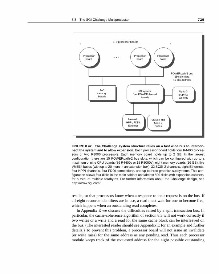
8.8 The SGI Challenge Multiprocessor 729
bus. If free,
. Inly ifed onurtheridatecessornding
results, so that processors know when a response to their request is on theall eight resource identifiers are in use, a read must wait for one to becomewhich happens when an outstanding read completes.
In Appendix E we discuss the difficulties raised by a split transaction busparticular, the cache-coherence algorithm of section 8.3 will not work correcttwo writes or a write and a read for the same cache block can be interleavthe bus. (The interested reader should see Appendix E for an example and fdetails.) To prevent this problem, a processor board will not issue an inval(or write miss) for the same address as any pending read. Thus each promodule keeps track of the requested address for the eight possible outsta
FIGURE 8.42 The Challenge system structure relies on a fast wide bus to intercon-nect the system and to allow expansion. Each processor board holds four R4400 proces-sors or two R8000 processors. Each memory board holds up to 2 GB. In the largestconfiguration there are 15 POWERpath-2 bus slots, which can be configured with up to amaximum of nine CPU boards (36 R4400s or 18 R8000s), eight memory boards (16 GB), fiveVME64 buses (with up to 20 more in an extension box), 32 SCSI-2 channels, eight Ethernets,four HPPI channels, four FDDI connections, and up to three graphics subsystems. This con-figuration allows four disks in the main cabinet and almost 500 disks with expansion cabinets,for a total of multiple terabytes. For further information about the Challenge design, seehttp://www.sgi.com/.
Processorboard
Processorboard
Processorboard
1–9 processor boards
POWERpath-2 bus256 bits data
40 bits address
1–8memory boards
I/O system:1–4 POWERchannel
boards
Network:HPPI, FDDI,
Ethernet
VME64 andSCSI-2buses
Up to 3graphicssystems

730 Chapter 8 Multiprocessors
d andss forhen
D), thes. to in-ps cand ther re-If thek in ae in-
pies and
uest-case,rst- orta, thisster
ack re-ate andbitratedad re-
eachoard.ledge.On thetrans-
576-gleter-time bus
reads. If a write miss occurs for a read that is pending, the processor is stallethe write is delayed. If a processor board receives a read miss for an addrewhich a read is pending, the later read can “piggyback” on the earlier read. Wthe response to the earlier read appears (tagged with the correct resource Ibus interface simply grabs the data and uses it to satisfy the later cache mis
For each of the eight read resources there is an inhibit line, which is used dicate that a read request should not be responded to by the memory. Snootake variable amounts of time, depending on the state of the processor anblock, so this signal is critical to implementing coherence. When a processoceives a snoop request, it asserts the inhibit line until it completes its snoop. snoop either finds that the cache does not have the block or finds the blocclean state, the processor drops the inhibit line. If all the processors drop thhibit line, the memory will respond, since it knows that all the processor coare clean. If a processor finds a dirty copy of the block, it requests the busplaces the data on the bus, after which it drops the inhibit line. Both the reqing processor and the memory receive the data and write it. In this latter since there are separate tags for snooping, and retrieving a value from the fisecond-level cache takes much longer than detecting the presence of the dasolution of letting memory respond when its copy is valid is considerably fathan always intervening.
The data and address buses are separately arbitrated and used. Write-bquests use both buses, read responses use only the data bus, and invalidread requests use only the address bus. Since the buses are separately arand assigned, the combined pair of buses can simultaneously carry a new request and a response to an earlier request.
On POWERpath-2, each bus transaction consists of five bus clock cycles,20 ns in length, that are executed in parallel by the bus controllers on each bThese five cycles are arbitration, resolution, address, decode, and acknowOn the address bus, one address is sent in the five-cycle bus transaction. data bus, four 256-bit data transfers are performed during the five-cycle bus action. Thus the sustained bus transfer rate is
(256/8) bytes/transfer × (1000/20) bus cycles/microsecond
× (4/5) transfers/bus cycle = 1.28 GB/sec
To obtain high bandwidth from memory, each memory board provides a bit path to the DRAMs (512 bits of data and 64 bits of ECC), allowing a sinmemory cycle to provide the data for two bus transfers. Thus with two-way inleaving a single memory board can support the full bus bandwidth.The total to satisfy a read miss for a 128-byte cache block with no contention is 22clock cycles:
1. The initial read request is one bus transaction of five bus clock cycles.
2. The latency until memory is ready to transfer is 12 bus clock cycles.
8.8 The SGI Challenge Multiprocessor 731
ans-
s, as-e replynsac-
he la-essor
ory a misscessdress
clock
takes
ntire. Theal bus the
ary
clocksoces-. This ac-
oces- theseessorsion.nder-execu-
3. The reply transfers all 128 bytes in one reply transaction (four 256-bit trfers), taking five bus clock cycles.
Thus, latency of the access from the processor viewpoint is 22 bus clock cyclesuming that the memory access can start when the address is received and thtransaction can start immediately after the data is available. The bus is split tration, so other requests and replies can occur during the memory access time.
Thus to calculate the secondary cache miss time, we need to compute ttency of each step from the point a memory address is issued until the procis restarted after the miss:
1. The first step is the initial detection of the miss and generation of the memrequest by the processor. This process consists of three steps: detectingin the primary on-chip cache; initiating a secondary (off-chip) cache acand detecting a miss in the secondary cache; and driving the complete adoff-chip through the system bus. This process takes about 40 processorcycles.
2. The next step is the bus and memory system component, which we know22 bus clock cycles.
3. The next step is reloading the cache line. The R4400 is stalled until the ecache block is reloaded, so the reload time is added into the miss timememory interface on the processor is 64 bits and operates at the externtiming of 50 MHz, which is the same as the bus timing. Thus reloading128-byte cache block takes 16 bus clock cycles.
4. Finally, 10 additional processor clock cycles are used to reload the primcache and restart the pipeline.
The total miss penalty for a secondary cache miss consists of 50 processor plus 38 bus clocks. For a 150-MHz R4400, each bus clock (20 ns) is three prsor clocks (6.67 ns), so the miss time is 164 processor clocks, or 1093 nsnumber is considerably larger than it would be for a uniprocessor memorycess, as we discuss in section 8.9. The next section discusses performance.
Performance of the Parallel Program Workload on Challenge
Figure 8.43 shows the speedup for our applications running on up to 16 prsors. The speedups for 16 processors vary from 10.5 to 15.0. Becausebenchmarks have been tuned to improve memory behavior, the uniprocversion of the parallel benchmark is better than the original uniprocessor verThus we report speedup relative to the uniprocessor parallel version. To ustand what’s behind the speedups, we can examine the components of the tion time.

732 Chapter 8 Multiprocessors
po-ime. pro-
by theop-off mostroni-sents fixedmindses andors arearly,
Figure 8.44 shows how the total execution time is composed of three comnents: CPU time, memory overhead or stall time, and synchronization wait tWith the data in Figure 8.44, we can explain the speedup behavior of thesegrams. For example, FFT shows the most linear speedup, as can be seennearly constant processor utilization. Both Barnes and Ocean have some drin speedup due to slight increases in synchronization overhead. LU has thesignificant loss of speedup, which arises from a significant increase in synchzation overhead. Interestingly, this synchronization overhead actually repreload imbalance, which becomes a serious problem as the ratio between aproblem size and the number of processors decreases. Figure 8.44 also reus that speedup is a dangerous measure to use by itself. For example, BarnOcean have nearly identical speedup at 16 processors, but the 16 processbusy 70% of the time in Barnes and only 43% of the time in Ocean. CleBarnes makes much more effective use of the Challenge multiprocessor.
FIGURE 8.43 The speedups for the parallel benchmarks are shown versus processorcount for a 150-MHz R4400 Challenge system. The superlinear speedup for Ocean run-ning on two processors occurs because of the doubling of the available cache.
Speed-up
0
4
8
14
12
10
6
2
FFT
12.0
3.9
7.8
15.0
LU Barnes
Benchmarks
Ocean
16
11.9
3.5
6.4
10.5
11.9
3.7
6.9
13.5
12.1
4.4
8.6
13.7
1 2 4 8 16

8.8 The SGI Challenge Multiprocessor 733
FIGURE 8.44 The components of execution time for the four parallel benchmarks running on a Challenge multi-processor with 1 to 16 150-MHz R4400. Although memory stalls are a problem with all processor counts, synchronizationstalls become more severe as the processor count is increased. Synchronization stalls often result from load balancing, asin LU, or from contention arising when synchronization becomes very frequent, as in Ocean. These applications have beentuned to have good locality and low miss rates, which keep memory stalls from becoming an increasing problem with largerprocessor counts.
Percentage oftotal execution time
0%
30%
20%
10%
1 2 4
Processor count
FFT
8 16
100%
40%
70%
90%
80%
60%
50% Percentage oftotal execution time
0%
30%
20%
10%
1 2 4
Processor count
LU
8 16
100%
40%
70%
90%
80%
60%
50%
Percentage oftotal execution time
0%
30%
20%
10%
1 2 4
Processor count
Barnes
8 16
100%
40%
70%
90%
80%
60%
50% Percentage oftotal execution time
0%
30%
20%
10%
1 2 4
Processor count
Ocean
8 16
100%
40%
70%
90%
80%
60%
50%
CPU busy time Memory overhead Synchronization
734 Chapter 8 Multiprocessors
are un-ulti-have
sus
ow-ed to paral- therfor- on a
ess- col-
lgo- may thanlgo-ntiallent
ir, al-ncoun-cache.rickyines ma-icky, valid
(seeever,
Given the lack of maturity in our understanding of parallel computing, theremany hidden pitfalls that will be uncovered either by careful designers or byfortunate ones. Given the large amount of hype that often surrounds mprocessors, especially at the high end, common fallacies abound. We included a selection of these.
Pitfall: Measuring performance of multiprocessors by linear speedup verexecution time.
“Mortar shot” graphs—plotting performance versus number of processors shing linear speedup, a plateau, and then a falling off—have long been usjudge the success of parallel processors. Although speedup is one facet of alel program, it is not a direct measure of performance. The first question ispower of the processors being scaled: A program that linearly improves pemance to equal 100 Intel 8080s may be slower than the sequential versionworkstation. Be especially careful of floating-point-intensive programs; procing elements without hardware assist may scale wonderfully but have poorlective performance.
Comparing execution times is fair only if you are comparing the best arithms on each machine. Comparing the identical code on two machinesseem fair, but it is not; the parallel program may be slower on a uniprocessora sequential version. Developing a parallel program will sometimes lead to arithmic improvements, so that comparing the previously best-known sequeprogram with the parallel code—which seems fair—will not compare equivaalgorithms. To reflect this issue, the terms relative speedup (same program) andtrue speedup (best program) are sometimes used. Results that suggest super-linear performance, when a program on n processors is more than n times fasterthan the equivalent uniprocessor, may indicate that the comparison is unfathough there are instances where “real” superlinear speedups have been etered. For example, when Ocean is run on two processors, the combined produces a small superlinear speedup (2.1 vs. 2.0), as shown in Figure 8.43
In summary, comparing performance by comparing speedups is at best tand at worst misleading. Comparing the speedups for two different machdoes not necessarily tell us anything about the relative performance of thechines. Even comparing two different algorithms on the same machine is trsince we must use true speedup, rather than relative speedup, to obtain acomparison.
Fallacy: Amdahl’s Law doesn’t apply to parallel computers.
In 1987, the head of a research organization claimed that Amdahl’s Law section 1.6) had been broken by an MIMD machine. This hardly meant, how
8.9 Fallacies and Pitfalls
8.9 Fallacies and Pitfalls 735
on of re-
ex-om-me
st besay
n of
s thedata setxecu-ntiald the
s truecan
st is,e canllarsgners
h noel ofeimpleem-roces-
bus.andces-400cessor
esignf-the- they
that the law has been overturned for parallel computers; the neglected portithe program will still limit performance. To understand the basis of the mediaports, let’s see what Amdahl [1967] originally said:
A fairly obvious conclusion which can be drawn at this point is that the effortpended on achieving high parallel processing rates is wasted unless it is accpanied by achievements in sequential processing rates of very nearly the samagnitude. [p. 483]
One interpretation of the law was that since portions of every program musequential, there is a limit to the useful economic number of processors—100. By showing linear speedup with 1000 processors, this interpretatioAmdahl’s Law was disproved.
The basis for the statement that Amdahl’s Law had been “overcome” wause of scaled speedup.The researchers scaled the benchmark to have a size that is 1000 times larger and compared the uniprocessor and parallel etion times of the scaled benchmark. For this particular algorithm the sequeportion of the program was constant independent of the size of the input, anrest was fully parallel—hence, linear speedup with 1000 processors.
We have already described the dangers of relating scaled speedup aspeedup. Additional problems with this sort of scaling methodology, which result in unrealistic running times, were examined in section 8.7.
Fallacy: Multiprocessors are “free.”
This fallacy has two different interpretations, and both are erroneous. The firgiven that modern microprocessors contain support for snooping caches, wbuild small-scale, bus-based multiprocessors for no additional cost in do(other than the microprocessor cost) or sacrifice of performance. Many desibelieved this to be true and have even tried to build machines to prove it.
To understand why this doesn’t work, you need to compare a design witmultiprocessing extensibility against a design that allows for a moderate levmultiprocessing (say 2–4 processors). The 2–4 processor design requires somsort of bus and a coherence controller that is more complicated than the smemory controller required for the uniprocessor design. Furthermore, the mory access time is almost always faster in the uniprocessor case, since the psor can be directly connected to memory with only a simple single-masterThus the strictly uniprocessor solution typically has better performance lower cost than the 1-processor configuration of even a very small multiprosor. For example, a typical Silicon Graphics workstation using 150-MHz R4has a miss penalty that is under 80 processor clocks versus the 164 proclocks seen on a Challenge.
It also became popular in the 1980s to believe that the multiprocessor dwas free in the sense that an MP could be quickly constructed from state-oart microprocessors and then quickly updated using newer processors as
736 Chapter 8 Multiprocessors
andhichoft-ed for
earch mid- aom a thatnvest- net-
ca-th of
e bi-bus- bus-
ch asle tol ma-ires auser. The with
can in-ses.)uses.a bus-
hatcon- pro-mall
may
r, a
became available. This viewpoint ignores the complexity of cache coherencethe challenge of designing high-bandwidth, low-latency memory systems, wfor modern processors is extremely difficult. Moreover, there is additional sware effort: compilers, operating systems, and debuggers all must be adapta parallel system. The next two fallacies are closely related to this one.
Fallacy: Scalability is almost free.
The goal of scalable parallel computing has been a focus of much of the resand a significant segment of the high-end machine development since the1980s. Until recently, it was widely held that you could build scalability intomultiprocessor and then simply offer the machine at any point on the scale frsmall number of processors to a large number. The difficulty with this view ismachines that scale to larger processor counts require substantially more iment (in both dollars and design time) in the interprocessor communicationwork, as well as in aspects such as reliability and reconfigurability.
As an example, consider the CM-5. It provides an interconnection networkpable of scaling to 4000 processors, where it can deliver a bisection bandwid20 GB/sec. At a more typical 32- to 64-processor configuration, however, thsection bandwidth is only 160–320 MB/sec, which is less than what most based systems provide. Furthermore, the cost per CPU is higher than in abased system in this range.
The cost of scalability can be seen even in more limited design ranges, suvery small MP systems (2–8 processors) versus bus-based systems that sca16–32 processors. Although a fast 64-bit bus might be adequate for a smalchine with fewer than four processors, a larger number of processors requwider, higher bandwidth bus (for example, the 256-bit Challenge bus). The who buys the large system pays for the cost of this high-performance busSPARCCenter 2000 design addresses this by using a multiple bus designnarrower buses. In a small system, only one bus is needed; a larger system clude two buses. (In fact, a version of this design from Cray can have four buInterleaved memory allows transfers to be done simultaneously on both bEven in this case, scalability still has a cost, since each processor requires snooping ASIC for each bus in the system.
Scalability is also not free in software: To build software applications tscale requires significantly more attention to load balance, locality, potential tention for shared resources, and the serial (or partly parallel) portions of thegram. Obtaining scalability for real applications, as opposed to toys or skernels, across factors of more than 10 in processor count, is a major challenge.In the future, better compiler technology and performance analysis tools help with this critical problem.
Pitfall: Not developing the software to take advantage of, or optimize fomultiprocessor architecture.
8.9 Fallacies and Pitfalls 737
ma-mpleslop-le to from
em-ldingulti-
ess re-h theuesory
cationlocalnd aing.
localgners
whenment.singles notme a
t usesstat- pro-e pagel thatllo-tion
haseckaral-roces-
at oneue to
lockce isugs soft-
There is a long history of software lagging behind on massively parallel chines, possibly because the software problems are much harder. Two exafrom mainstream, bus-based multiprocessors illustrate the difficulty of deveing software for new multiprocessors. The first has to do with not being abtake advantage of a potential architectural capability, and the second arisesthe need to optimize the software for a multiprocessor.
The SUN SPARCCenter is a bus-based machine with one or two buses. Mory is distributed on the boards with the processors to create a simple buiblock consisting of processor, cache, and memory. With this structure, the mprocessor could also have a fast local access and use the bus only to accmote memory. The SUN operating system, however, was not able to deal witNUMA (non-uniform memory access) aspect of memory, including such issas controlling where memory was allocated (local versus global). If mempages were allocated randomly, then successive runs of the same applicould have substantially different performance, and the benefits of fast access might be small or nonexistent. In addition, providing both a remote alocal access path to memory slightly complicated the design because of timSince the software would not have been able to take advantage of fastermemory and the design was believed to be more complicated, the desidecided to require all requests to go over the bus.
Our second example shows the subtle kinds of problems that can arise software designed for a uniprocessor is adapted to a multiprocessor environThe SGI operating system protects the page table data structure with a lock, assuming that page allocation is infrequent. In a uniprocessor this doerepresent a performance problem. In a multiprocessor situation, it can becomajor performance bottleneck for some programs. Consider a program thaa large number of pages that are initialized at start-up, which UNIX does for ically allocated pages. Suppose the program is parallelized so that multiplecesses allocate the pages. Because page allocation requires the use of thtable data structure, which is locked whenever it is in use, even an OS kerneallows multiple threads in the OS will be serialized if the processes all try to acate their pages at once (which is exactly what we might expect at initializatime!).
This page table serialization eliminates parallelism in initialization and significant impact on overall parallel performance. This performance bottlenpersists even under multiprogramming. For example, suppose we split the plel program apart into separate processes and run them, one process per psor, so that there is no sharing between the processes. (This is exactly whuser did, since he reasonably believed that the performance problem was dunintended sharing or interference in his application.) Unfortunately, the still serializes all the processes—so even the multiprogramming performanpoor. This pitfall indicates the kind of subtle but significant performance bthat can arise when software runs on multiprocessors. Like many other key

738 Chapter 8 Multiprocessors
ht in affec-
e.
re. Ased for% of miss-
e localverage
tion be re-ote CPIs, the
o not the wasodes
.
s tohow-s uni-ys that
ssors,st de-ssor.
ssording useletee unitssor8.8.
ware components, the OS algorithms and data structures must be rethougmultiprocessor context. Placing locks on smaller portions of the page table etively eliminates the problem.
Pitfall: Neglecting data distribution in a distributed shared-memory machin
Consider the Ocean benchmark running on a 32-processor DSM architectuFigure 8.26 (page 687) shows, the miss rate is 3.1%. Because the grid usthe calculation is allocated in a tiled fashion (as described on page 654), 2.5the accesses are local capacity misses and 0.6% are remote communicationes needed to access data at the boundary of each grid. Assuming a 30-cyclmemory access cost and a 100-cycle remote memory access cost, the amiss has a cost of 43.5 cycles.
If the grid was allocated in a straightforward fashion by round-robin allocaof the pages, we could expect 1/32 of the misses to be local and the rest tomote. This would lead to local miss rate of and a remmiss rate of 3.0%, for an average miss cost of 96.8 cycles. If the averagewithout cache misses is 1.5, and 45% of the instructions are data referenceversion with tiled allocation is
This analysis only considers latency, and assumes that contention effects dlead to increased latency, which is very optimistic. Round-robin is also notworst possible data allocation: if the grid fit in a subset of the memory andallocated to only a subset of the nodes, contention for memory at those ncould easily lead to a difference in performance of more than a factor of 2.
Fallacy: Linear speedups are needed to make multiprocessors cost-effective
It is widely recognized that one of the major benefits of parallel computing ioffer a “shorter time to solution” than the fastest uniprocessor. Many people, ever, also hold the view that parallel processors cannot be as cost-effective aprocessors unless they can achieve perfect linear speedup. This argument sabecause the cost of the machine is a linear function of the number of proceanything less than linear speedup means that the ratio of performance/cocreases, making a parallel processor less cost-effective than using a uniproce
The problem with this argument is that cost is not only a function of procecount, but also depends on memory (as well as I/O). The effect of inclumemory in the system cost was pointed out by Wood and Hill [1995], and wean example from their article to demonstrate the effect of looking at a compsystem. They compare a uniprocessor server, the Challenge DM (a desksidwith one processor and up to 6 GB of memory), against a multiproceChallenge XL, the rack-mounted multiprocessor we examined in section
3.1% 1 32⁄× 0.1%=
1.5 45% 3.1%× 96.8×+1.5 45% 3.1%× 43.5×+------------------------------------------------------------- 1.5 1.35+
1.5 0.61+------------------------ 2.85
2.11---------- 1.35 times faster= = =

8.9 Fallacies and Pitfalls 739
MHz
n the0 +dups
XL isedup
roces-
dup of cost
ead,e. Ifle theds toeds tost ef-or ex-B of
XLrs. o in-nce ispari-
(The XL also has faster processors than those of the Challenge DM—150 versus 100 MHz—but we will ignore this difference.)
First, Wood and Hill introduce a cost function: cost (p, m), which equals thelist price of a machine with p processors and m megabytes of memory. For theChallenge DM:
For the Challenge XL:
Suppose our computation requires 1 GB of memory on either machine. Thecost of the DM is $138,400, while the cost of the Challenge XL is $181,60$20,000 × p. For different numbers of processors, we can compute what speeare necessary to make the use of parallel processing on the XL more cost effec-tive than that of the uniprocessor. For example, the cost of an 8-processor $341,600, which is about 2.5 times higher than the DM, so if we have a speon 8 processors of more than 2.5, the multiprocessor is actually more cost effec-tive than the uniprocessor. If we are able to achieve linear speedup, the 8-psor XL system is actually more than three times more cost effective! Things getbetter with more processors: On 16 processors, we need to achieve a speeonly 3.6, or less than 25% parallel efficiency, to make the multiprocessor aseffective as the uniprocessor.
The use of a multiprocessor may involve some additional memory overhalthough this number is likely to be small for a shared-memory architecturwe assume an extremely conservative number of 100% overhead (i.e., doubmemory is required on the multiprocessor), the 8-processor machine neeachieve a speedup of 3.2 to break even, and the 16-processor machine neachieve a speedup of 4.3 to break even. Surprisingly, the XL can even be cofective when compared against a headless workstation used as a server. Fample, the cost function for a Challenge S, which can have at most 256 Mmemory, is
For problems small enough to fit in 256 MB of memory on both machines, thebreaks even with a speedup of 6.3 on 8 processors and 10.1 on 16 processo
In comparing the cost/performance of two computers, we must be sure tclude accurate assessments of both total system cost and what performaachievable. For many applications with larger memory demands, such a comson can dramatically increase the attractiveness of using a multiprocessor.
tcos 1 m,( ) $38,400 $100 m×+=
tcos p m,( ) $81,600 $20,000 p× $100 m×+ +=
tcos 1 m,( ) $16,600 $100 m×+=
740 Chapter 8 Multiprocessors
of a be
r as idity
been andte of pro-rove
er, in-m-
andec-hitec-ry of
ds toulti-
t this
tood.pu-
pu-ism.en foruch
e andnsivet re-ccesseveralcuss
terscro-
For over a decade prophets have voiced the contention that the organizationsingle computer has reached its limits and that truly significant advances canmade only by interconnection of a multiplicity of computers in such a manneto permit cooperative solution. …Demonstration is made of the continued valof the single processor approach. … [p. 483]
Amdahl [1967]
The dream of building computers by simply aggregating processors has around since the earliest days of computing. However, progress in buildingusing effective and efficient parallel processors has been slow. This raprogress has been limited by difficult software problems as well as by a longcess of evolving architecture of multiprocessors to enhance usability and impefficiency. We have discussed many of the software challenges in this chaptcluding the difficulty of writing programs that obtain good speedup due to Adahl’s law, dealing with long remote access or communication latencies,minimizing the impact of synchronization. The wide variety of different archittural approaches and the limited success and short life of many of the arctures to date has compounded the software difficulties. We discuss the histothe development of these machines in section 8.11.
Despite this long and checkered past, progress in the last 10 years leasome reasons to be optimistic about the future of parallel processing and mprocessors. This optimism is based on a number of observations abouprogress and the long-term technology directions:
1. The use of parallel processing in some domains is beginning to be undersProbably first among these is the domain of scientific and engineering comtation. This application domain has an almost limitless thirst for more comtation. It also has many applications that have lots of natural parallelNonetheless, it has not been easy: programming parallel processors evthese applications remains very challenging. Another important, and mlarger (in terms of market size), application area is large-scale data bastransaction processing systems. This application domain also has extenatural parallelism available through parallel processing of independenquests, but its needs for large-scale computation, as opposed to purely ato large-scale storage systems, are less well understood. There are also scontending architectural approaches that may be viable—a point we disshortly.
2. It is now widely held that one of the most effective ways to build computhat offer more performance than that achieved with a single-chip mi
8.10 Concluding Remarks
8.10 Concluding Remarks 741
rice/ely to
arevers,re, forrces,
large OSom-
ulti-ularlyively
ng as
)
melyic forr moreaddi-d onost-uchts of
omi-resent
ill bemar-d for
processor is by building a multiprocessor that leverages the significant pperformance advantages of mass-produced microprocessors. This is likbecome more true in the future.
3. Multiprocessors are highly effective for multiprogrammed workloads thatoften the dominant use of mainframes and large servers, including file serwhich handle a restricted type of multiprogrammed workload. In the futusuch workloads may well constitute a large portion of the market needhigher-performance machines. When the workload wants to share resousuch as file storage, or can efficiently timeshare a resource, such as amemory, a multiprocessor can be a very efficient host. Furthermore, thesoftware needed to efficiently execute multiprogrammed workloads is becing commonplace.
While there is reason to be optimistic about the growing importance of mprocessors, many areas of parallel architecture remain unclear. Two particimportant questions are, How will the largest-scale multiprocessors (the massparallel processors, or MPPs) be built? and What is the role of multiprocessia long-term alternative to higher-performance uniprocessors?
The Future of MPP Architecture
Hennessy and Patterson should move MPPs to Chapter 11.
Jim Gray, when asked about coverage of MPPsin the second edition of this book, alludes to Chapter 11 bankruptcy protection in U.S. law (1995
Small-scale multiprocessors built using snooping-bus schemes are extrecost-effective. Recent microprocessors have even included much of the logcache coherence in the processor chip, and several allow the buses of two oprocessors to be directly connected—implementing a coherent bus with no tional logic. With modern integration levels, multiple processors can be placea board, or even on a single multi-chip module (MCM), resulting in a highly ceffective multiprocessor. Using DSM technology it is possible to configure s2–4 processor nodes into a coherent structure with relatively small amounadditional hardware. It is premature to predict that such architectures will dnate the middle range of processor counts (16–64), but it appears at the pthat this approach is the most attractive.
What is totally unclear at the present is how the very largest machines wconstructed. The difficulties that designers face include the relatively small ket for very large machines (> 64 nodes and often > $5 million) and the nee

742 Chapter 8 Multiprocessors
ive at thecale
nter- thatssagee co-ma-is notmpat-ma-
withsuchse of
turalr fits thatram-r to a
hichential ma-
net-hichcon-al.
stom of thee dis-sageents
cost ma-xam-
etech-nter-n the). Of
machines that scale to larger processor counts to be extremely cost-effectthe lower processor counts where most of the machines will be sold. Atpresent there appear to be four slightly different alternatives for large-smachines:
1. Large-scale machines that simply scale up naturally, using proprietary iconnect and communications controller technology. This is the approachhas been followed so far in machines like the Intel Paragon, using a mepassing approach, and Cray T3D, using a shared memory without cachherence. There are two primary difficulties with such designs. First, the chines are not cost-effective at small scales, where the cost of scalability valued. Second, these machines have programming models that are incoible, in varying degrees, with the mainstream of smaller and midrange chines.
2. Large-scale machines constructed from clusters of mid range machinescombinations of proprietary and standard technologies to interconnect machines. This cluster approach gets its cost-effectiveness through the ucost-optimized building blocks. In some approaches, the basic architecmodel (e.g., coherent shared memory) is extended. The Convex Exemplain this class. The disadvantage of trying to build this extended machine ismore custom design and interconnect are needed. Alternatively, the progming model can be changed from shared memory to message passing odifferent variation on shared memory, such as shared virtual memory, wmay be totally transparent. The disadvantage of such designs is the potchange in the programming model; the advantage is that the large-scalechine can make use of more off-the-shelf technology, including standardworks. Another example of such a machine is the SGI Challenge array, wis built from SGI Challenge machines and uses standard HPPI for its internect. Overall, this class of machine, while attractive, remains experiment
3. Designing machines that use off-the-shelf uniprocessor nodes and a cuinterconnect. The advantage of such a machine is the cost-effectivenessstandard uniprocessor node, which is often a repackaged workstation; thadvantage is that the programming model will probably need to be mespassing even at very small node counts. In some application environmwhere little or no sharing occurs, this may be acceptable. In addition, theof the interconnect, because it is custom, can be significant, making thechine costly, especially at small node counts. The IBM SP-2 is the best eple of this approach today.
4. Designing a machine using all off-the-shelf components, which promises thlowest cost. The leverage in this approach lies in the use of commodity nology everywhere: in the processors (PC or workstation nodes), in the iconnect (high-speed local area network technology, such as ATM), and isoftware (standard operating systems and programming languages

8.10 Concluding Remarks 743
likelyigns.and-ost-ch to pro- thesesta-uc-ion-nes.
impor-icationer-s may
diza-hes.
to try the in a in- forentsim-
in thest 10eas-ill
y. havexter-t yet
n thecerns
o notgle-
ancehe
course, such machines will use message passing, and communication isto have higher latency and lower bandwidth than in the alternative desLike the previous class of designs, for applications that do not need high bwidth or low-latency communication, this approach can be extremely ceffective. Databases and file servers, for example, may be a good matthese machines. Also, for multiprogrammed workloads, where each usercess is independent of the others, this approach is very attractive. Todaymachines are built as workstation clusters or as NOWs (networks of worktions) or COWs (clusters of workstations). The VAXCluster approach scessfully used this organization for multiprogrammed and transactoriented workloads, albeit with minicomputers rather than desktop machi
Each of these approaches has advantages and disadvantages, and thetance of the shortcomings of any one approach are dependent on the applclass. In 1995 it is unclear which if any of these models will win out for largscale machines. For some classes of applications, one of these approacheeven become dominant for small to midrange machines. Finally, some hybrition of these ideas may emerge, given the similarity in several of the approac
The Future of Microprocessor Architecture
As we saw in Chapter 4, architects are using ever more complex techniquesto exploit more instruction-level parallelism. As we also saw in that chapter,prospects for finding ever-increasing amounts of instruction-level parallelismmanner that is efficient to exploit are somewhat limited. Likewise, there arecreasingly difficult problems to be overcome in building memory hierarchieshigh-performance processors. Of course, continued technology improvemwill allow us to continue to advance clock rate. But the use of technology provements that allow a faster gate speed alone is not sufficient to maintaincredible growth of performance that the industry has experienced in the payears. Maintaining a rapid rate of performance growth will depend to an incring extent on exploiting the dramatic growth in effective silicon area, which wcontinue to grow much faster than the basic speed of the process technolog
Unfortunately, for the past five or more years, increases in performance come at the cost of ever-increasing inefficiencies in the use of silicon area, enal connections, and power. This diminishing-returns phenomenon has noslowed the growth of performance in the mid 1990s, but we cannot sustairapid rate of performance improvements without addressing these conthrough new innovations in computer architecture.
Unlike the prophets quoted at the beginning of the chapter, your authors dbelieve that we are about to “hit a brick wall” in our attempts to improve sinprocessor performance. Instead, we may see a gradual slowdown in performgrowth, with the eventual growth being limited primarily by improvements in t

744 Chapter 8 Multiprocessors
rd toch a an-
h inrowthd an!be a di-per-singmorysses.used
user evo-tures whost in-
s, but of an
hes,. Theo 10havehinesmul-f ma-
posehe ex-possi- the soft-rallel
ry.
speed of the technology. When these limitation will become serious is hasay, but possibly as early as the beginning of the next century. Even if suslowdown were to occur, performance might well be expected to grow at thenual rate of 1.35 that we saw prior to 1985.
Furthermore, we do not want to rule out the possibility of a breakthrouguniprocessor design. In the early 1980s, many people predicted the end of gin uniprocessor performance, only to see the arrival of RISC technology anunprecedented 10-year growth in performance averaging 1.6 times per year
With this in mind, we cautiously ask whether the long-term direction will to use increased silicon to build multiple processors on a single chip. Suchrection is appealing from the architecture viewpoint—it offers a way to scale formance without increasing complexity. It also offers an approach to easome of the challenges in memory-system design, since a distributed mecan be used to scale bandwidth while maintaining low latency for local acceThe challenge lies in software and in what architecture innovations may be to make the software easier.
Evolution Versus Revolution and the Challenges to Paradigm Shifts in the Computer Industry
Figure 8.45 shows what we mean by the evolution-revolution spectrum of com-puter architecture innovation. To the left are ideas that are invisible to the (presumably excepting better cost, better performance, or both). This is thelutionary end of the spectrum. At the other end are revolutionary architecideas. These are the ideas that require new applications from programmermust learn new programming languages and models of computation, and muvent new data structures and algorithms.
Revolutionary ideas are easier to get excited about than evolutionary ideato be adopted they must have a much higher payoff. Caches are an exampleevolutionary improvement. Within 5 years after the first publication about cacalmost every computer company was designing a machine with a cacheRISC ideas were nearer to the middle of the spectrum, for it took closer tyears for most companies to have a RISC product. Most multiprocessors tended to the revolutionary end of the spectrum, with the largest-scale mac(MPPs) being more revolutionary than others. Most programs written to use tiprocessors as parallel engines have been written especially for that class ochines, if not for the specific architecture.
The challenge for both hardware and software designers that would prothat multiprocessors and parallel processing become the norm, rather than tception, is the disruption to the established base of programs. There are two ble ways this paradigm shift could be facilitated: if parallel processing offersonly alternative to enhance performance, and if advances in hardware andware technology can construct a gentle ramp that allows the movement to paprocessing, at least with small numbers of processors, to be more evolutiona
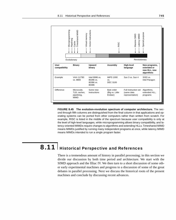
8.11 Historical Perspective and References 745
n we the oth- greatesent
There is a tremendous amount of history in parallel processing; in this sectiodivide our discussion by both time period and architecture. We start withSIMD approach and the Illiac IV. We then turn to a short discussion of someer early experimental machines and progress to a discussion of some of thedebates in parallel processing. Next we discuss the historical roots of the prmachines and conclude by discussing recent advances.
FIGURE 8.45 The evolution-revolution spectrum of computer architecture. The sec-ond through fifth columns are distinguished from the final column in that applications and op-erating systems can be ported from other computers rather than written from scratch. Forexample, RISC is listed in the middle of the spectrum because user compatibility is only atthe level of high-level languages, while microprogramming allows binary compatibility, and la-tency-oriented MIMDs require changes to algorithms and extending HLLs. Timeshared MIMDmeans MIMDs justified by running many independent programs at once, while latency MIMDmeans MIMDs intended to run a single program faster.
8.11 Historical Perspective and References
SISD vs. Intel Paragon
Algorithms,extended HLL,programs
High-levellanguage
Sun 3 vs. Sun 4
Full instruction set(same datarepresentation)
Assembly
MIPS 1000vs.DEC 3100
Byte order(Big vs. LittleEndian)
Upwardbinary
Intel 8086 vs.80286 vs.80386 vs.80486
Some new instructions
Binary
VAX-11/780vs. 8800
Microcode,TLB, caches,pipelining,MIMD
Usercompatibility
Example
Difference
New programs,extended ornew HLL, newalgorithms
RevolutionaryEvolutionary
Spe
cial
pur
pose
Late
ncy
MIM
D
Mas
sive
SIM
D
RIS
C
Vec
tor
inst
ruct
ions
Virt
ual m
emor
y
Tim
esha
red
MIM
DC
ache
Pip
elin
ing
Mic
ropr
ogra
mm
ing
746 Chapter 8 Multiprocessors
n op-ding
ne of
tingthat that
lot- ba-ects.laterte inthenitialtoneer-nnyad
ons.nd ad-s ares. Forn.m-
op-f da-achwhatt the
rsusllelism, for 64
The Rise and Fall of SIMD Computers
The cost of a general multiprocessor is, however, very high and further desigtions were considered which would decrease the cost without seriously degrathe power or efficiency of the system. The options consist of recentralizing othe three major components.... Centralizing the [control unit] gives rise to thebasic organization of [an]... array processor such as the Illiac IV.
Bouknight et al. [1972]
The SIMD model was one of the earliest models of parallel computing, daback to the first large-scale multiprocessor, the Illiac IV. The key idea in machine, as in more recent SIMD machines, is to have a single instructionoperates on many data items at once, using many functional units.
The earliest ideas on SIMD-style computers are from Unger [1958] and Snick, Borck, and McReynolds [1962]. Slotnick’s Solomon design formed thesis of the Illiac IV, perhaps the most infamous of the supercomputer projWhile successful in pushing several technologies that proved useful in projects, it failed as a computer. Costs escalated from the $8 million estima1966 to $31 million by 1972, despite construction of only a quarter of planned machine. Actual performance was at best 15 MFLOPS, versus ipredictions of 1000 MFLOPS for the full system [Hord 1982]. Delivered NASA Ames Research in 1972, the computer took three more years of engiing before it was usable. These events slowed investigation of SIMD, with DaHillis [1985] resuscitating this style in the Connection Machine, which h65,636 1-bit processors.
Real SIMD computers need to have a mixture of SISD and SIMD instructiThere is an SISD host computer to perform operations such as branches adress calculations that do not need parallel operation. The SIMD instructionbroadcast to all the execution units, each of which has its own set of registerflexibility, individual execution units can be disabled during a SIMD instructioIn addition, massively parallel SIMD machines rely on interconnection or comunication networks to exchange data between processing elements.
SIMD works best in dealing with arrays in for-loops. Hence, to have the portunity for massive parallelism in SIMD there must be massive amounts ota, or data parallelism. SIMD is at its weakest in case statements, where eexecution unit must perform a different operation on its data, depending on data it has. The execution units with the wrong data are disabled so thaproper units can continue. Such situations essentially run at 1/nth performance,where n is the number of cases.
The basic trade-off in SIMD machines is performance of a processor venumber of processors. Recent machines emphasize a large degree of paraover performance of the individual processors. The Connection Machine 2example, offered 65,536 single bit-wide processors, while the Illiac IV had64-bit processors.
8.11 Historical Perspective and References 747
byrpose. Aarchi-IMDerna-e and low-rs for
rposeial-
equirertainnits.
ut- im-rs. n theandctedsors
mod-espe-ster-time.cement de-hesemuch
aban-eply the
After being resurrected in the 1980s, first by Thinking Machines and thenMasPar, the SIMD model has once again been put to bed as a general-pumultiprocessor architecture, for two main reasons. First, it is too inflexiblenumber of important problems cannot use such a style of machine, and the tecture does not scale down in a competitive fashion; that is, small-scale Smachines often have worse cost/performance compared with that of the alttives. Second, SIMD cannot take advantage of the tremendous performanccost advantages of microprocessor technology. Instead of leveraging thiscost technology, designers of SIMD machines must build custom processotheir machines.
Although SIMD computers have departed from the scene as general-pualternatives, this style of architecture will continue to have a role in specpurpose designs. Many special-purpose tasks are highly data parallel and ra limited set of functional units. Thus designers can build in support for ceoperations, as well as hardwire interconnection paths among functional uSuch organizations are often called array processors, and they are useful fortasks like image and signal processing.
Other Early Experiments
It is difficult to distinguish the first multiprocessor. Surprisingly, the first comper from the Eckert-Mauchly Corporation, for example, had duplicate units toprove availability. Holland [1959] gave early arguments for multiple processo
Two of the best-documented multiprocessor projects were undertaken i1970s at Carnegie Mellon University. The first of these was C.mmp [Wulf Bell 1972; Wulf and Harbison 1978], which consisted of 16 PDP-11s conneby a crossbar switch to 16 memory units. It was among the first multiproceswith more than a few processors, and it had a shared-memory programmingel. Much of the focus of the research in the C.mmp project was on software, cially in the OS area. A later machine, Cm* [Swan et al. 1977], was a clubased multiprocessor with a distributed memory and a nonuniform access The absence of caches and a long remote access latency made data placritical. This machine and a number of application experiments are wellscribed by Gehringer, Siewiorek, and Segall [1987]. Many of the ideas in tmachines would be reused in the 1980s when the microprocessor made it cheaper to build multiprocessors.
Great Debates in Parallel Processing
The quotes at the beginning of this chapter give the classic arguments for doning the current form of computing, and Amdahl [1967] gave the classic rin support of continued focus on the IBM 370 architecture. Arguments for
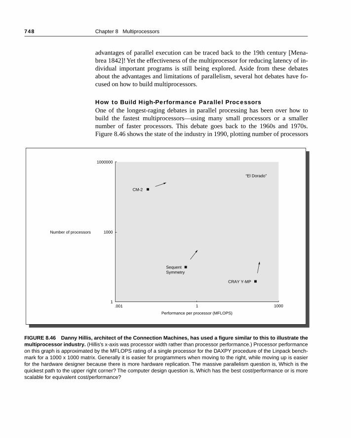
748 Chapter 8 Multiprocessors
ena-f in-atesve fo-
ow toaller
1970s.ssors
advantages of parallel execution can be traced back to the 19th century [Mbrea 1842]! Yet the effectiveness of the multiprocessor for reducing latency odividual important programs is still being explored. Aside from these debabout the advantages and limitations of parallelism, several hot debates hacused on how to build multiprocessors.
How to Build High-Performance Parallel ProcessorsOne of the longest-raging debates in parallel processing has been over hbuild the fastest multiprocessors—using many small processors or a smnumber of faster processors. This debate goes back to the 1960s and Figure 8.46 shows the state of the industry in 1990, plotting number of proce
FIGURE 8.46 Danny Hillis, architect of the Connection Machines, has used a figure similar to this to illustrate themultiprocessor industry. (Hillis’s x-axis was processor width rather than processor performance.) Processor performanceon this graph is approximated by the MFLOPS rating of a single processor for the DAXPY procedure of the Linpack bench-mark for a 1000 x 1000 matrix. Generally it is easier for programmers when moving to the right, while moving up is easierfor the hardware designer because there is more hardware replication. The massive parallelism question is, Which is thequickest path to the upper right corner? The computer design question is, Which has the best cost/performance or is morescalable for equivalent cost/performance?
1000000
Number of processors
“El Dorado”
CM-2
SequentSymmetry
CRAY Y-MP
Performance per processor (MFLOPS)
.001 1 10001
1000
8.11 Historical Perspective and References 749
stion El
ch of be thenge ishun-ds that
ction. roadntin-cture.
for out-th an
illion toentsrizehigh-n at
wouldm toPS
. This
e theould994 timesear
ighta se-fore
uper-uterschinesf theore
versus performance of an individual processor. The massive parallelism queis whether taking the high road or the low road in Figure 8.46 will get us toDorado—the highest-performance multiprocessor. In the last few years, muthis debate has subsided. Microprocessor-based machines are assumed tobasis for the highest-performance multiprocessors. Perhaps the biggest chathe perception that machines built from microprocessors will probably have dreds and perhaps a few thousand processors, but not the tens of thousanhad been predicted earlier.
In the last five years, the middle road has emerged as the most viable direIt combines moderate numbers of high-performance microprocessors. Thisrelies on advances in our ability to program parallel machines as well as on coued progress in microprocessor performance and advances in parallel archite
Predictions of the FutureIt’s hard to predict the future, yet in 1989 Gordon Bell made two predictions1995. We included these predictions in the first edition of the book, when thecome was completely unclear. We discuss them in this section, together wiassessment of the accuracy of the prediction.
The first is that a computer capable of sustaining a teraFLOPS—one mMFLOPS—will be constructed by 1995, either using a multicomputer with 4K32K nodes or a Connection Machine with several million processing elem[Bell 1989]. To put this prediction in perspective, each year the Gordon Bell Packnowledges advances in parallelism, including the fastest real program (est MFLOPS). In 1989 the winner used an eight-processor Cray Y-MP to ru1680 MFLOPS. On the basis of these numbers, machines and programs have to have improved by a factor of 3.6 each year for the fastest prograachieve 1 TFLOPS in 1995. In 1994, the winner achieved 140,000 MFLO(0.14 TFLOPS) using a 1904-node Paragon, which contains 3808 processorsrepresents a year-to-year improvement of 2.4, which is still quite impressive.
What has become recognized since 1989 is that although we may havtechnology to build a teraFLOPS machine, it is not clear either that anyone cafford it or that it would be cost-effective. For example, based on the 1winner, a sustained teraFLOPS would require a machine that is about sevenlarger and would likely cost close to $100 million. If factors of 2 in year-to-yperformance improvement can be sustained, the price of a teraFLOPS mreach a reasonable level in 1997 or 1998. Gordon Bell argued this point in ries of articles and lectures in 1992–93, using the motto “No teraFLOPS beits time.”
The second Bell prediction concerns the number of data streams in scomputers shipped in 1995. Danny Hillis believed that although supercompwith a small number of data streams may be the best sellers, the biggest mawill be machines with many data streams, and these will perform the bulk ocomputations. Bell bet Hillis that in the last quarter of calendar year 1995 msustained MFLOPS will be shipped in machines using few data streams (≤100)
750 Chapter 8 Multiprocessors
rs,lica-ointerur
Al-liclywithter ofat
useber of
therorsnd a fur-day’s
the Bellowedorta-d the
to
apsers tocom-phicsSe-n in
Baeriginal
rather than many data streams (≥1000). This bet concerns only supercomputedefined as machines costing more than $1 million and used for scientific apptions. Sustained MFLOPS is defined for this bet as the number of floating-poperations per month, so availability of machines affects their rating. The losmust write and publish an article explaining why his prediction failed; yoauthors will act as judge and jury.
In 1989, when this bet was made, it was totally unclear who would win.though it is a little too early to convene the court, a survey of the current pubknown supercomputers shows only six machines in existence in the world more than 1000 data streams. It is quite possible that during the last quar1995, no machines with ≥1000 data streams will ship. In fact, it appears thmuch smaller microprocessor-based machines (≤ 20 programs) are becomingdominant. A recent survey of the 500 highest-performance machines in(based on Linpack ratings), called the Top 500, showed that the largest nummachines were bus-based shared-memory multiprocessors!
More Recent Advances and Developments
With the exception of the parallel vector machines (see Appendix B), all orecent MIMD computers have been built from off-the-shelf microprocessusing a bus and logically central memory or an interconnection network adistributed memory. A number of experimental machines built in the 1980sther refined and enhanced the concepts that form the basis for many of tomultiprocessors.
The Development of Bus-Based Coherent MachinesAlthough very large mainframes were built with multiple processors in 1970s, multiprocessors did not become highly successful until the 1980s.[1985] suggests the key was that the smaller size of the microprocessor allthe memory bus to replace the interconnection network hardware, and that pble operating systems meant that multiprocessor projects no longer requireinvention of a new operating system. In this paper, Bell defines the terms multi-processor and multicomputer and sets the stage for two different approachesbuilding larger-scale machines.
The first bus-based multiprocessor with snooping caches was the SynN+1 described by Frank [1984]. Goodman [1983] wrote one of the first papedescribe snooping caches. The late 1980s saw the introduction of many mercial bus-based, snooping-cache architectures, including the Silicon Gra4D/240 [Baskett et al. 1988], the Encore Multimax [Wilson 1987], and the quent Symmetry [Lovett and Thakkar 1988]. The mid 1980s saw an explosiothe development of alternative coherence protocols, and Archibald and [1986] provide a good survey and analysis, as well as references to the orpapers.
8.11 Historical Perspective and References 751
eremulti-yper-bringIt in-stan-uteraseded net-lso
houghputa-
off-videdvinghe art
lude80;3], al.em-ated
as innces
o bens ofed ad-ped in
donerenceche-] andcto-ries
(nowt al.noski992]ry. It
Toward Large-Scale MultiprocessorsIn the effort to build large-scale multiprocessors, two different directions wexplored: message passing multicomputers and scalable shared-memory processors. Although there had been many attempts to build mesh and hcube-connected multiprocessors, one of the first machines to successfully together all the pieces was the Cosmic Cube built at Caltech [Seitz 1985]. troduced important advances in routing and interconnect technology and subtially reduced the cost of the interconnect, which helped make the multicompviable. The Intel iPSC 860, a hypercube-connected collection of i860s, was bon these ideas. More recent machines, such as the Intel Paragon, have usworks with lower dimensionality and higher individual links. The Paragon aemployed a separate i860 as a communications controller in each node, alta number of users have found it better to use both i860 processors for comtion as well as communication. The Thinking Machines CM-5 made use ofthe-shelf microprocessors and a fat tree interconnect (see Chapter 7). It prouser-level access to the communication channel, thus significantly improcommunication latency. In 1995, these two machines represent the state of tin message-passing multicomputers.
Early attempts at building a scalable shared-memory multiprocessor incthe IBM RP3 [Pfister et al. 1985], the NYU Ultracomputer [Schwartz 19Elder et al. 1985], the University of Illinois Cedar project [Gajksi et al. 198and the BBN Butterfly and Monarch [BBN Laboratories 1986; Rettberg et1990]. These machines all provided variations on a nonuniform distributed-mory model, but did not support cache coherence, which substantially complicprogramming. The RP3 and Ultracomputer projects both explored new idesynchronization (fetch-and-operate) as well as the idea of combining referein the network. In all four machines, the interconnect networks turned out tmore costly than the processing nodes, raising problems for smaller versiothe machine. The Cray T3D builds on these ideas, using a noncoherent shardress space but building on the advances in interconnect technology develothe multicomputer domain.
Extending the shared-memory model with scalable cache coherence wasby combining a number of ideas. Directory-based techniques for cache cohewere actually known before snooping cache techniques. In fact, the first cacoherence protocols actually used directories, as described by Tang [1976implemented in the IBM 3081. Censier and Feautrier [1978] described a direry coherence scheme with tags in memory. The idea of distributing directowith the memories to obtain a scalable implementation of cache coherencecalled distributed shared memory, or DSM) was first described by Agarwal e[1988] and served as the basis for the Stanford DASH multiprocessor (see Leet al. [1990, 1992]). The Kendall Square Research KSR-1 [Burkhardt et al.1was the first commercial implementation of scalable coherent shared memo
752 Chapter 8 Multiprocessors
bedaredod-
dules,
red-ver-es,
otherks,
hatriggsve
con-is col-n the
andppearpapersnc-
rchi- book
paral-SA con-gra-AQ.nows thatst not
extended the basic DSM approach to implement a concept called COMA (cache-only memory architecture), which makes the main memory a cache, as descriin Exercise 8.13. The Convex Exemplar implements scalable coherent shmemory using a two-level architecture: at the lowest level eight-processor mules are built using a crossbar. A ring can then connect up to 32 of these mofor a total of 256 processors.
Developments in Synchronization and Consistency Models A wide variety of synchronization primitives have been proposed for shamemory multiprocessors. Mellor-Crummey and Scott [1991] provide an oview of the issues as well as efficient implementations of important primitivsuch as locks and barriers. An extensive bibliography supplies references toimportant contributions, including developments in spin locks, queuing locand barriers.
Lamport [1979] introduced the concept of sequential consistency and wcorrect execution of parallel programs means. Dubois, Scheurich, and B[1988] introduced the idea of weak ordering (originally in 1986). In 1990, Adand Hill provided a better definition of weak ordering and also defined the cept of data-race-free; at the same conference, Gharachorloo [1990] and hleagues introduced release consistency and provided the first data operformance of relaxed consistency models.
Other References
There is an almost unbounded amount of information on multiprocessorsmulticomputers: Conferences, journal papers, and even books seem to afaster than any single person can absorb the ideas. No doubt many of these will go unnoticed—not unlike the past. Most of the major architecture conferees contain papers on multiprocessors. An annual conference, Supercomputing XY(where X and Y are the last two digits of the year), brings together users, atects, software developers, and vendors and publishes the proceedings inand CD-ROM form. Two major journals, Journal of Parallel and DistributedComputing and the IEEE Transactions on Parallel and Distributed Systems, con-tain papers on all aspects of parallel processing. Several books focusing on lel processing are included in the following references. Eugene Miya of NAAmes has collected an online bibliography of parallel-processing papers thattains more than 10,000 entries. To get information about receiving the bibliophy, see http://unix.hensa.ac.uk/parallel/bibliographies/parallelism-biblos-FAlso see [Miya 1985]. In addition to documenting the discovery of concepts used in practice, these references also provide descriptions of many ideahave been explored and found wanting, as well as ideas whose time has juyet come.
8.11 Historical Perspective and References 753
e
ale
es-
:
.
s-
t
/501
ter
References
ADVE, S. V. AND M. D. HILL [1990]. “Weak ordering—A new definition,” Proc. 17th Int’l Sympo-sium on Computer Architecture (June), Seattle, 2–14.
AGARWAL, A., J. L. HENNESSY, R. SIMONI, AND M.A. HOROWITZ [1988]. “An evaluation of direc-tory schemes for cache coherence,” Proc. 15th Int’l Symposium on Computer Architectur(June), 280–289.
ALMASI, G. S. AND A. GOTTLIEB [1989]. Highly Parallel Computing, Benjamin/Cummings, Red-wood City, Calif.
AMDAHL , G. M. [1967]. “Validity of the single processor approach to achieving large sccomputing capabilities,” Proc. AFIPS Spring Joint Computer Conf. 30, Atlantic City, N.J. (April),483–485.
ARCHIBALD, J. AND J.-L. BAER [1986]. “Cache coherence protocols: Evaluation using a multiprocsor simulation model,” ACM Trans. on Computer Systems 4:4 (November), 273–298.
BASKETT, F., T. JERMOLUK, AND D. SOLOMON [1988]. “The 4D-MP graphics superworkstationComputing + graphics = 40 MIPS + 40 MFLOPS and 10,000 lighted polygons per second,” Proc.COMPCON Spring, San Francisco, 468–471.
BBN LABORATORIES [1986]. “Butterfly parallel processor overview,” Tech. Rep. 6148, BBN Labo-ratories, Cambridge, Mass.
BELL, C. G. [1985]. “Multis: A new class of multiprocessor computers,” Science 228 (April 26), 462–467.
BELL, C. G. [1989]. “The future of high performance computers in science and engineering,” Comm.ACM 32:9 (September), 1091–1101.
BOUKNIGHT, W. J, S. A. DENEBERG, D. E. MCINTYRE, J. M. RANDALL , A. H. SAMEH, AND D. L.SLOTNICK [1972]. “The Illiac IV system,” Proc. IEEE 60:4, 369–379. Also appears in D. PSiewiorek, C. G. Bell, and A. Newell, Computer Structures: Principles and Examples, McGraw-Hill, New York (1982), 306–316.
BURKHARDT, H. III, S. FRANK, B. KNOBE, AND J. ROTHNIE [1992]. “Overview of the KSR1 computersystem,” Tech. Rep. KSR-TR-9202001, Kendall Square Research, Boston (February).
CENSIER, L. AND P. FEAUTRIER [1978]. “A new solution to coherence problems in multicache sytems,” IEEE Trans. on Computers C-27:12 (December), 1112–1118.
DUBOIS, M., C. SCHEURICH, AND F. BRIGGS [1988]. “Synchronization, coherence, and evenordering,” IEEE Computer 9-21 (February).
EGGERS, S. [1989]. Simulation Analysis of Data Sharing in Shared Memory Multiprocessors, Ph.D.Thesis, Univ. of California, Berkeley. Computer Science Division Tech. Rep. UCB/CSD 89(April).
ELDER, J., A. GOTTLIEB, C. K. KRUSKAL, K. P. MCAULIFFE, L. RANDOLPH, M. SNIR, P. TELLER, AND
J. WILSON [1985]. “Issues related to MIMD shared-memory computers: The NYU Ultracompuapproach,” Proc. 12th Int’l Symposium on Computer Architecture (June), Boston, 126–135.
FLYNN, M. J. [1966]. “Very high-speed computing systems,” Proc. IEEE 54:12 (December), 1901–1909.
FRANK, S. J. [1984] “Tightly coupled multiprocessor systems speed memory access time,” Electron-ics 57:1 (January), 164–169.
GAJSKI, D., D. KUCK, D. LAWRIE, AND A. SAMEH [1983]. “CEDAR—A large scale multiprocessor,”Proc. Int’l Conf. on Parallel Processing (August), 524–529.
GEHRINGER, E. F., D. P. SIEWIOREK, AND Z. SEGALL [1987]. Parallel Processing: The Cm* Experi-ence, Digital Press, Bedford, Mass.
GHARACHORLOO, K., D. LENOSKI, J. LAUDON, P. GIBBONS, A. GUPTA, AND J. L. HENNESSY [1990].“Memory consistency and event ordering in scalable shared-memory multiprocessors,” Proc. 17thInt’l Symposium on Computer Architecture (June), Seattle, 15–26.
754 Chapter 8 Multiprocessors
pro-
cess
io-
r-
s
GOODMAN, J. R. [1983]. “Using cache memory to reduce processor memory traffic,” Proc. 10th Int’lSymposium on Computer Architecture (June), Stockholm, Sweden, 124–131.
HILLIS, W. D. [1985]. The Connection Machine, MIT Press, Cambridge, Mass.
HOCKNEY, R. W. AND C. R. JESSHOPE [1988]. Parallel Computers-2, Architectures, Programmingand Algorithms, Adam Hilger Ltd., Bristol, England.
HOLLAND, J. H. [1959]. “A universal computer capable of executing an arbitrary number of subgrams simultaneously,” Proc. East Joint Computer Conf. 16, 108–113.
HORD, R. M. [1982]. The Illiac-IV, The First Supercomputer, Computer Science Press, Rockville, Md.
HWANG, K. [1993]. Advanced Computer Architecture and Parallel Programming, McGraw-Hill,New York.
LAMPORT, L. [1979]. “How to make a multiprocessor computer that correctly executes multiproprograms,” IEEE Trans. on Computers C-28:9 (September), 241–248.
LENOSKI, D., J. LAUDON, K. GHARACHORLOO, A. GUPTA, AND J. L. HENNESSY [1990]. “The Stan-ford DASH multiprocessor,” Proc. 17th Int’l Symposium on Computer Architecture (June), Seattle,148–159.
LENOSKI, D., J. LAUDON, K. GHARACHORLOO, W.-D. WEBER, A. GUPTA, J. L. HENNESSY, M. A.HOROWITZ, AND M. LAM [1992]. “The Stanford DASH multiprocessor,” IEEE Computer 25:3(March).
LOVETT, T. AND S. THAKKAR [1988]. “The Symmetry multiprocessor system,” Proc. 1988 Int’l Conf.of Parallel Processing, University Park, Penn., 303–310.
MELLOR-CRUMMEY, J. M. AND M. L. SCOTT [1991]. “Algorithms for scalable synchronization onshared-memory multiprocessors,” ACM Trans. on Computer Systems 9:1 (February), 21–65.
MENABREA, L. F. [1842]. “Sketch of the analytical engine invented by Charles Babbage,” Bibthèque Universelle de Genève (October).
MITCHELL, D. [1989]. “The Transputer: The time is now,” Computer Design (RISC supplement), 40–41.
MIYA , E. N. [1985]. “Multiprocessor/distributed processing bibliography,” Computer ArchitectureNews (ACM SIGARCH) 13:1, 27–29.
PFISTER, G. F., W. C. BRANTLEY, D. A. GEORGE, S. L. HARVEY, W. J. KLEINFEKDER, K. P. MCAU-
LIFFE, E. A. MELTON, V. A. NORTON, AND J. WEISS [1985]. “The IBM research parallel processoprototype (RP3): Introduction and architecture,” Proc. 12th Int’l Symposium on Computer Architecture (June), Boston, 764–771.
RETTBERG, R. D., W. R. CROWTHER, P. P. CARVEY, AND R. S. TOWLINSON [1990]. “The Monarchparallel processor hardware design,” IEEE Computer 23:4 (April).
ROSENBLUM, M., S. A. HERROD, E. WITCHEL, AND A. GUTPA [1995]. “Complete computer simula-tion: The SimOS approach,” to appear in IEEE Parallel and Distributed Technology 3:4 (fall).
SCHWARTZ, J. T. [1980]. “Ultracomputers,” ACM Trans. on Programming Languages and System4:2, 484–521.
SEITZ, C. [1985]. “The Cosmic Cube,” Comm. ACM 28:1 (January), 22–31.
SLOTNICK, D. L., W. C. BORCK, AND R. C. MCREYNOLDS [1962]. “The Solomon computer,” Proc.Fall Joint Computer Conf. (December), Philadelphia, 97–107.
STONE, H. [1991]. High Performance Computers, Addison-Wesley, New York.
SWAN, R. J., A. BECHTOLSHEIM, K. W. LAI, AND J. K. OUSTERHOUT [1977]. “The implementation ofthe Cm* multi-microprocessor,” Proc. AFIPS National Computing Conf., 645–654.
SWAN, R. J., S. H. FULLER, AND D. P. SIEWIOREK [1977]. “Cm*—A modular, multi-microproces-sor,” Proc. AFIPS National Computer Conf. 46, 637–644.

Exercises 755
es-
ort
ssors serialent in
timesotocol. can be ma-ith a
tocol
d bithout
hilere in-bility
TANG, C. K. [1976]. “Cache design in the tightly coupled multiprocessor system,” Proc. AFIPSNational Computer Conf., New York (June), 749–753.
UNGER, S. H. [1958]. “A computer oriented towards spatial problems,” Proc. Institute of RadioEnginers 46:10 (October), 1744–1750.
WILSON, A. W., JR. [1987]. “Hierarchical cache/bus architecture for shared-memory multiprocsors,” Proc. 14th Int’l Symposium on Computer Architecture (June), Pittsburgh, 244–252.
WOOD, D. A. AND M. D. HILL [1995]. “Cost-effective parallel computing,” IEEE Computer 28:2(February).
WULF, W. AND C. G. BELL [1972]. “C.mmp—A multi-mini-processor,” Proc. AFIPS Fall JointComputing Conf. 41, part 2, 765–777.
WULF, W. AND S. P. HARBISON [1978]. “Reflections in a pool of processors—An experience repon C.mmp/Hydra,” Proc. AFIPS 1978 National Computing Conf. 48 (June), Anaheim, Calif., 939–951.
E X E R C I S E S
8.1 [10] <8.1> Suppose we have an application that runs in three modes: all proceused, half the processors in use, and serial mode. Assume that 0.02% of the time ismode, and there are 100 processors in total. Find the maximum time that can be spthe mode when half the processors are used, if our goal is a speedup of 80.
8.2 [15] <8.1> Assume that we have a function for an application of the form F(i,p), whichgives the fraction of time that exactly i processors are usable given that a total of p proces-sors are available. This means that
Assume that when i processors are in use, the application runs i times faster. RewriteAmdahl’s Law so that it gives the speedup as a function of p for some application.
8.3 [15] <8.3> In small bus-based multiprocessors, write-through caches are someused. One reason is that a write-through cache has a slightly simpler coherence prShow how the basic snooping cache coherence protocol of Figure 8.12 on page 665changed for a write-through cache. From the viewpoint of an implementor, what is thejor hardware functionality that is not needed with a write-through cache compared wwrite-back cache?
8.4 [20] <8.3> Add a clean private state to the basic snooping cache-coherence pro(Figure 8.12 on page 665). Show the protocol in the format of Figure 8.12.
8.5 [15] <8.3> One proposed solution for the problem of false sharing is to add a valiper word (or even for each byte). This would allow the protocol to invalidate a word witremoving the entire block, allowing a cache to keep a portion of a block in its cache wanother processor wrote a different portion of the block. What extra complications atroduced into the basic snooping cache coherency protocol (Figure 8.12) if this capais included? Remember to consider all possible protocol actions.
F i,p( ) 1=
i 1=
p
∑
756 Chapter 8 Multiprocessors
atery sys-
ncesk much
n up-
date and
utedaches,e, and
f locals traf-
es, as-ps andnge bus.rency used 25 bus
k run6 one using
e canedi-
uregures.
ner-plete clockfor theon 32
nectses in
8.6 [12/10/15] <8.3> The performance differences for write invalidate and write updschemes can arise from both bandwidth consumption and latency. Assume a memotem with 64-byte cache blocks. Ignore the effects of contention.
a. [12] <8.3> Write two parallel code sequences to illustrate the bandwidth differebetween invalidate and update schemes. One sequence should make update loobetter and the other should make invalidate look much better.
b. [10] <8.3> Write a parallel code sequence to illustrate the latency advantage of adate scheme versus an invalidate scheme.
c. [15] <8.3> Show, by example, that when contention is included, the latency of upmay actually be worse. Assume a bus-based machine with 50-cycle memorysnoop transactions.
8.7 [15/15] <8.3–8.4> One possible approach to achieving the scalability of distribshared memory and the cost-effectiveness of a bus design is to combine the two approusing a set of nodes with memories at each node, a hybrid cache-coherence scheminterconnected with a bus. The argument in favor of such a design is that the use omemories and a coherence scheme with limited broadcast results in a reduction in bufic, allowing the bus to be used for a larger number of processors. For these Exercissume the same parameters as for the Challenge bus. Assume that remote snoomemory accesses take the same number of cycles as a memory access on the ChalleIgnore the directory processing time for these Exercises. Assume that the cohescheme works as follows on a miss: If the data are up-to-date in the local memory, it isthere. Otherwise, the bus is used to snoop for the data. Assume that local misses takeclocks.
a. [15] <8.3–8.4> Find the time for a read or write miss to data that are remote.
b. [15] <8.3–8.4> Ignoring contention and using the data from the Ocean benchmaron 16 processors for the frequency of local and remote misses (Figure 8.2page 687), estimate the average memory access time versus that for a Challengthe same total miss rate.
8.8 [20/15] <8.4> If an architecture allows a relaxed consistency model, the hardwarimprove the performance of write misses by allowing the write miss to proceed immately, buffering the write data until ownership is obtained.
a. [20] <8.4> Modify the directory protocol in Figure 8.24 on page 683 and in Fig8.25 on page 684 to do this. Show the protocol in the same format as these two fi
b. [15] <8.4> Assume that the write buffer is large enough to hold the write until owship is granted, and that write ownership and any required invalidates always combefore a release is reached. If the extra time to complete a write is 100 processorcycles and writes generate 40% of the misses, find the performance advantage relaxed consistency machines versus the original protocol using the FFT data processors (Figure 8.26 on page 687).
8.9 [12/15] <8.3,8.4,8.8> Although it is widely believed that buses are the ideal interconfor small-scale multiprocessors, this may not always be the case. For example, increa
Exercises 757
imple- the busmory
ce on
cachea mem-cessor
bits. As- mes- Findmoteaction
y ac-
riess asr
nt. In32 tomple,ory isoblemis pro-rcises.
ma-nd di-e rootmoryte thes, as-bothodes.
of 50ached. for aench-
ses oc-crossies?
processor performance are lowering the processor count at which a more distributed mentation becomes attractive. Because a standard bus-based implementation usesboth for access to memory and for interprocessor coherency traffic, it has a uniform meaccess time for both. In comparison, a distributed memory implementation may sacrifiremote memory access, but it can have a much better local memory access time.
Consider the design of a DSM multiprocessor with 16 processors. Assume the R4400miss overheads shown for the Challenge design (see pages 730–731). Assume that ory access takes 150 ns from the time the address is available from either the local proor a remote processor until the first word is delivered.
a. [12] <8.3,8.4,8.8> How much faster is a local access than on the Challenge?
b. [15] <8.3,8.4,8.8> Assume that the interconnect is a 2D grid with links that are 16wide and clocked at 100 MHz, with a start-up time of five cycles for a messagesume one clock cycle between nodes in the network, and ignore overhead in thesages and contention (i.e., assume that the network bandwidth is not the limit).the average remote memory access time, assuming a uniform distribution of rerequests. How does this compare to the Challenge case? What is the largest frof remote misses for which the DSM machine will have a lower average memorcess time than that of the Challenge machine?
8.10 [20/15/30] <8.4> One downside of a straightforward implementation of directousing fully populated bit vectors is that the total size of the directory information scalethe product: Processor count × Memory blocks. If memory is grown linearly with processocount, then the total size of the directory grows quadratically in the processor coupractice, because the directory needs only 1 bit per memory block (which is typically 128 bytes), this problem is not serious for small to moderate processor counts. For exaassuming a 128-byte block, the amount of directory storage compared to main memProcessor count/1024, or about 10% additional storage with 100 processors. This prcan be avoided by observing that we only need to keep an amount of information that portional to the cache size of each processor. We explore some solutions in these Exe
a. [20] <8.4> One method to obtain a scalable directory protocol is to organize thechine as a logical hierarchy with the processors at the leaves of the hierarchy arectories positioned at the root of each subtree. The directory at each subtrerecords which descendents cache which memory blocks, as well as which meblocks with a home in that subtree are cached outside of the subtree. Compuamount of storage needed to record the processor information for the directoriesuming that each directory is fully associative. Your answer should incorporate the number of nodes at each level of the hierarchy as well as the total number of n
b. [15] <8.4> Assume that each level of the hierarchy in part (a) has a lookup cost cycles plus a cost to access the data or cache of 50 cycles, when the point is reWe want to compute the AMAT (average memory access time—see Chapter 5)64-processor machine with four-node subtrees. Use the data from the Ocean bmark run on 64 processors (Figure 8.26) and assume that all noncoherence miscur within a subtree node and that coherence misses are uniformly distributed athe machine. Find the AMAT for this machine. What does this say about hierarch
758 Chapter 8 Multiprocessors
ple-es ther. Us- four-
areectoryy hass the fieldhichior ofto focushe di-
toler-ed initch
d pro-arallel
s to an-dled.
igurete ac-ake 120t affect
ine. sig-
ces-ity as
ts. This) orry ar-a in
us, ahitec-hard-entuallycture.
c. [30] <8.4> An alternative approach to implementing directory schemes is to imment bit vectors that are not dense. There are two such strategies: one reducnumber of bit vectors needed and the other reduces the number of bits per vectoing traces, you can compare these schemes. First, implement the directory as away set-associative cache storing full bit vectors, but only for the blocks thatcached outside of the home node. If a directory cache miss occurs, choose a direntry and invalidate the entry. Second, implement the directory so that every entr8 bits. If a block is cached in only one node outside of its home, this field containnode number. If the block is cached in more than one node outside its home, thisis a bit vector with each bit indicating a group of eight processors, at least one of wcaches the block. Using traces of 64-processor execution, simulate the behavthese two schemes. Assume a perfect cache for nonshared references, so as on coherency behavior. Determine the number of extraneous invalidations as trectory cache size is increased.
8.11 [25/40] <8.7> Prefetching and relaxed consistency models are two methods of ating the latency of longer access in multiprocessors. Another scheme, originally usthe HEP multiprocessor and incorporated in the MIT Alewife multiprocessor, is to swto another activity when a long-latency event occurs. This idea, called multiple context ormultithreading, works as follows:
■ The processor has several register files and maintains several PCs (and relategram states). Each register file and PC holds the program state for a separate pthread.
■ When a long-latency event occurs, such as a cache miss, the processor switcheother thread, executing instructions from that thread while the miss is being han
a. [25] <8.7> Using the data for the Ocean benchmark running on 64 processors (F8.26), determine how many contexts are needed to hide all the latency of remocesses. Assume that local cache misses take 40 cycles and that remote misses tcycles. Assume that the increased demands due to a higher request rate do noeither the latency or the bandwidth of communications.
b. [40] <8.7> Implement a simulator for a multiple-context directory-based machUse the simulator to evaluate the performance gains from multiple context. Hownificant are contention and the added bandwidth demands in limiting the gains?
8.12 [25] <8.7> Prove that in a two-level cache hierarchy, where L1 is closer to the prosor, inclusion is maintained with no extra action if L2 has at least as much associativL1, both caches use LRU replacement, and both caches have the same block size.
8.13 [20] <8.4,8.9> As we saw in Fallacies and Pitfalls, data distribution can be importanwhen an application has a nontrivial private data miss rate caused by capacity misseproblem can be attacked with compiler technology (distributing the data in blocksthrough architectural support. One architectural technique is called cache-only memochitecture (COMA), a version of which was implemented in the KSR-1. The basic ideCOMA is to make the distributed memories into caches, so that blocks can be replicatedand migrated at the memory level of the hierarchy, as well as in higher levels. ThCOMA architecture can change what would be remote capacity misses on a DSM arcture into local capacity misses, by creating copies of data in the local memory. This ware capability allows the software to ignore the initial distribution of data to differmemories. The hardware required to implement a cache in the local memory will uslead to a slight increase in the memory access time of the memory on a COMA archite
Exercises 759
es areMA
issesng theon the
otocole spin
cks.
cre-
e with
sis-partialu havet, be-
gs al-
n de- hier-ncy ofsee if.
s for, and tontroller8.4 to
llows
As-
ier.
tem.ors to
Assume that we have a DSM and a COMA machine where remote coherence missuniformly distributed and take 100 clocks. Assume that all capacity misses on the COmachine hit in the local memory and require 50 clock cycles. Assume that capacity mtake 40 cycles when they are local on the DSM machine and 75 cycles otherwise. UsiOcean data for 32 processors (Figure 8.13), find what fraction of the capacity misses DSM machine must be local if the performance of the two machines is identical.
8.14 [15] <8.5> Some machines have implemented a special broadcast coherence prjust for locks, sometimes even using a different bus. Evaluate the performance of thlock in the Example on page 699 assuming a write broadcast protocol.
8.15 [15] <8.5> Implement the barrier in Figure 8.34 on page 701, using queuing loCompare the performance to the spin-lock barrier.
8.16 [15] <8.5> Implement the barrier in Figure 8.34 on page 701, using fetch-and-inment. Compare the performance to the spin-lock barrier.
8.17 [15] <8.5> Implement the barrier on page 705, so that barrier release is also dona combining tree.
8.18 [28] <8.6> Write a set of programs so that you can distinguish the following contency models: sequential consistency, processor consistency or total store order, store order, weak ordering, and release consistency. Using multiprocessors that yoaccess to, determine what consistency model different machines support. Note thacause of timing, you may need to try accesses multiple times to uncover all orderinlowed by a machine.
8.19 [30] <8.3–8.5> Using an available shared-memory multiprocessor, see if you catermine the organization and latencies of its memory hierarchy. For each level of thearchy, you can look at the total size, block size, and associativity, as well as the lateeach level of the hierarchy. If the machine uses a nonbus interconnection network, you can discover the topology, latency, and bandwidth characteristics of the network
8.20 [20] <8.4> As we discussed earlier, the directory controller can send invalidatelines that have been replaced by the local cache controller. To avoid such messageskeep the directory consistent, replacement hints are used. Such messages tell the cothat a block has been replaced. Modify the directory coherence protocol of section use such replacement hints.
8.21 [25] <8.6> Prove that for synchronized programs, a release consistency model aonly the same results as sequential consistency.
8.22 [15] <8.5> Find the time for n processes to synchronize using a standard barrier. sume that the time for a single process to update the count and release the lock is c.
8.23 [15] <8.5> Find the time for n processes to synchronize using a combining tree barrAssume that the time for a single process to update the count and release the lock is c.
8.24 [25] <8.5> Implement a software version of the queuing lock for a bus-based sysUsing the model in the Example on page 699, how long does it take for 20 processacquire and release the lock? You need only count bus cycles.
760 Chapter 8 Multiprocessors
ea offavor and
ciseal ma-
ansfer0 cy- over-MA
for
or in-nlyster??
re—
0% of
ingrojectsolutehanges What
that also resultorse
nce
worsethe mul-r thanat give
lbeitation.
uni- What
ulti-
8.25 [20/30] <8.2–8.5> Both researchers and industry designers have explored the idhaving the capability to explicitly transfer data between memories. The argument in of such facilities is that the programmer can achieve better overlap of computationcommunication by explicitly moving data when it is available. The first part of this exerexplores the potential on paper; the second explores the use of such facilities on rechines.
a. [20] <8.2–8.5> Assume that cache misses stall the processor, and that block troccurs into the local memory of a DSM node. Assume that remote misses cost 10cles and that local misses cost 40 cycles. Assume that each DMA transfer has anhead of 10 cycles. Assuming that all the coherence traffic can be replaced with Dinto main memory followed by a cache miss, find the potential improvementOcean running on 64 processors (Figure 8.26).
b. [30] <8.2–8.5> Find a machine that implements both shared memory (coherent coherent) and a simple DMA facility. Implement a blocked matrix multiply using oshared memory and using the DMA facilities with shared memory. Is the latter faHow much? What factors make the use of a block data transfer facility attractive
8.26 [Discussion] <8.8> Construct a scenario whereby a truly revolutionary architectupick your favorite candidate—will play a significant role. Significant is defined as 10% ofthe computers sold, 10% of the users, 10% of the money spent on computers, or 1some other figure of merit.
8.27 [40] <8.2,8.7,8.9> A multiprocessor or multicomputer is typically marketed usprograms that can scale performance linearly with the number of processors. The phere is to port programs written for one machine to the others and to measure their abperformance and how it changes as you change the number of processors. What cneed to be made to improve performance of the ported programs on each machine?is the ratio of processor performance according to each program?
8.28 [35] <8.2,8.7,8.9> Instead of trying to create fair benchmarks, invent programsmake one multiprocessor or multicomputer look terrible compared with the others, andprograms that always make one look better than the others. It would be an interestingif you couldn’t find a program that made one multiprocessor or multicomputer look wthan the others. What are the key performance characteristics of each organization?
8.29 [40] <8.2,8.7,8.9> Multiprocessors and multicomputers usually show performaincreases as you increase the number of processors, with the ideal being n times speedupfor n processors. The goal of this biased benchmark is to make a program that getsperformance as you add processors. For example, this means that one processor on tiprocessor or multicomputer runs the program fastest, two are slower, four are slowetwo, and so on. What are the key performance characteristics for each organization thinverse linear speedup?
8.30 [50] <8.2,8.7,8.9> Networked workstations can be considered multicomputers, awith somewhat slower, though perhaps cheaper, communication relative to computPort multicomputer benchmarks to a network using remote procedure calls for commcation. How well do the benchmarks scale on the network versus the multicomputer?are the practical differences between networked workstations and a commercial mcomputer?

Blank