Embed Size (px)
Citation preview
1
Hierarchical Checking of Multiprocessors UsingWatchdog Processors
I. Majzik++, A. Pataricza+,++, M. Dal Cin+, W. Hohl+, J. Hönig +,V. Sieh +
+ Universität Erlangen-Nürnberg, IMMD III, Germany++ Technical University of Budapest, BME MMT, Hungary
Abstract. A new control flow checking scheme, based on assigned-signaturechecking by a watchdog processor, is presented. This scheme is suitable for amultitasking, multiprocessor environment. The hardware overhead is compara-tively low because of three reasons: first, hierarchically structured, the schemeuses only a single watchdog processor to monitor multiple processes or proces-sors. Second, as an assigned-signature scheme it does not require monitoring theinstruction bus of the processors. Third, the run-time and reference signatures areembedded into the checked program; thus, in the watchdog processor neither areference database nor a time-consuming search and compare engine is required.
1 Introduction
Massively parallel computing systems running computing intensive applications de-mand a high degree of fault-tolerance. Fault-tolerance techniques require error detec-tion mechanisms with high coverage and low latency. As the majority of failures resultsfrom transient faults, concurrent fault detection is of utmost interest. However, with theincreasing number of processing units and parallel processes, concurrent fault detectionbecomes more and more difficult.
Since the majority of transient processor faults results in control-flow disturbances,a widely used concurrent error detection method is concurrent control flow checking us-ing a watchdog processor (WP). A WP is a relatively simple coprocessor that comparesthe actual control flow - represented by run-time signatures - with the previously com-puted reference control flow. WPs can be used to perform other checks as well [7], likeassertions on the data. The coprocessor-approach offers a possibility to connect a singleWP to multiple processors, reducing the hardware overhead.
Most of the WP implementations presented in the literature check single processors.They can be grouped according to the way run-time signatures are generated and thesource of reference. Some typical methods are presented in Table 1. The methods usingderived run-time signatures monitor and compact the state of the processor bus. As-signed run-time signatures are computed and inserted into the program source by a pre-compiler; they are transferred to the WP by the checked processor itself. The referenceis either a stored database of the admissible signature sequences or a special WP pro-gram of signature evaluation instructions.(In [6] the main processor itself emulates thesignature checker by utilizing unused resources). A further possibility is to transfer thereference signatures to the WP at run-time explicitly, using special instructions embed-ded into the program of the checked processor.
Additionally, different approaches to integrate watchdog processors into multipro-
In: Proc. Dependable Computing-EDCC-1, Berlin, Germany, October 4-6, 1994Springer LNCS 852, 1994, S.386-403

2
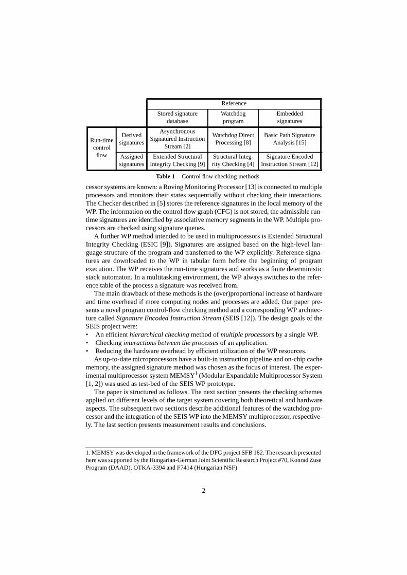
cessor systems are known: a Roving Monitoring Processor [13] is connected to multipleprocessors and monitors their states sequentially without checking their interactions.The Checker described in [5] stores the reference signatures in the local memory of theWP. The information on the control flow graph (CFG) is not stored, the admissible run-time signatures are identified by associative memory segments in the WP. Multiple pro-cessors are checked using signature queues.
A further WP method intended to be used in multiprocessors is Extended StructuralIntegrity Checking (ESIC [9]). Signatures are assigned based on the high-level lan-guage structure of the program and transferred to the WP explicitly. Reference signa-tures are downloaded to the WP in tabular form before the beginning of programexecution. The WP receives the run-time signatures and works as a finite deterministicstack automaton. In a multitasking environment, the WP always switches to the refer-ence table of the process a signature was received from.
The main drawback of these methods is the (over)proportional increase of hardwareand time overhead if more computing nodes and processes are added. Our paper pre-sents a novel program control-flow checking method and a corresponding WP architec-ture called Signature Encoded Instruction Stream (SEIS [12]). The design goals of theSEIS project were:• An efficient hierarchical checking method of multiple processors by a single WP.• Checking interactions between the processes of an application.• Reducing the hardware overhead by efficient utilization of the WP resources.
As up-to-date microprocessors have a built-in instruction pipeline and on-chip cachememory, the assigned signature method was chosen as the focus of interest. The exper-imental multiprocessor system MEMSY1 (Modular Expandable Multiprocessor System[1, 2]) was used as test-bed of the SEIS WP prototype.
The paper is structured as follows. The next section presents the checking schemesapplied on different levels of the target system covering both theoretical and hardwareaspects. The subsequent two sections describe additional features of the watchdog pro-cessor and the integration of the SEIS WP into the MEMSY multiprocessor, respective-ly. The last section presents measurement results and conclusions.
1. MEMSY was developed in the framework of the DFG project SFB 182. The research presentedhere was supported by the Hungarian-German Joint Scientific Research Project #70, Konrad ZuseProgram (DAAD), OTKA-3394 and F7414 (Hungarian NSF)
Reference
Stored signaturedatabase
Watchdogprogram
Embeddedsignatures
Run-timecontrol
flow
Derivedsignatures
AsynchronousSignatured Instruction
Stream [2]
Watchdog DirectProcessing [8]
Basic Path SignatureAnalysis [15]
Assignedsignatures
Extended StructuralIntegrity Checking [9]
Structural Integ-rity Checking [4]
Signature EncodedInstruction Stream [12]
Table 1 Control flow checking methods
3
2 Levels of Concurrent Error Detection
Our method is intended for use in multiprocessors with a UNIX-like operating system,widely used in massively parallel multiprocessors for scientific computations. An ap-plication consists of processes running the application program written in a proceduralprogramming language (e.g. C, Pascal). Programs contain procedures composed ofstatements. At each level (process, procedure and statement) a different checking meth-od and WP module is used.
2.1 Statement Level Checking
The execution sequence of statements in a program can be associated with a programcontrol flow graph (CFG). Vertices represent branch-free statement sequences, edgesrepresent the syntactically correct control flow between them. The CFG can be extract-ed by syntax analysis of the program source. Interrupts, data dependencies in condition-al branches, and procedure calls referenced by pointers raise special problems.Conditional branches allow typically two outgoing edges from a vertex, procedure callsmay call any other procedure, and interrupts, resulting in a call to an interrupt handlingprocedure, may occur at any time. The latter two problems belong to the procedure leveland are covered in the next subsection.
The statement level WP module checks the correct execution order of statements bycomparison with the corresponding paths in the CFG. In order to identify the state ofprogram execution, statement labels are assigned to the vertices of the CFG. These la-bels are explicitly transferred to the WP. The transfer instructions and the label valuesare inserted into the high level source text by a precompiler.
Statement labels identify not only the CFG vertices but their (syntactically) validsuccessor vertices as well. Thus, checking of the statement label sequence is based onlyon the presently checked label and its predecessor. This eliminates the need of a WP ref-erence database. Hence, the evaluation of the correctness of program flow is a simplecombinatorial task without any time consuming database search, allowing high speedprocessing. The label assignment algorithm of the precompiler is as follows (for a moreformal description see [11]):
1. The CFG of the procedure is extracted. The basic control structures form sub-graphs of the CFG. These subgraphs are identified according to the requirements ofthe encoding algorithm: that is, the number of successors of a vertex is limited inorder to reduce the information to be encoded in the label identifying them. Thesubgraphs are composed to form the CFG of a procedure.
2. The edges of the CFG are collected into an edge trail. The problem of edge collec-tion can be solved by well-known methods of Eulerian circuit generation.
3. A cyclic ordering of label values is defined and the edge trail is encoded. Adjacentvertices of the CFG are encoded by subsequent label values and different trails areseparated by unused sublabels. After encoding the trail, all labels corresponding tothe same vertex (called sublabels) are concatenated defining the statement label. In

4
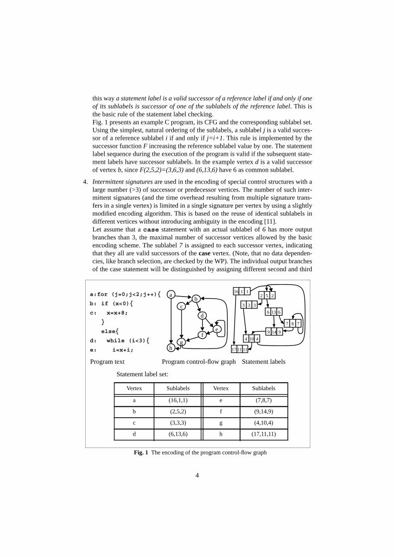
this way a statement label is a valid successor of a reference label if and only if oneof its sublabels is successor of one of the sublabels of the reference label. This isthe basic rule of the statement label checking.Fig. 1 presents an example C program, its CFG and the corresponding sublabel set.Using the simplest, natural ordering of the sublabels, a sublabel j is a valid succes-sor of a reference sublabel i if and only if j=i+1. This rule is implemented by thesuccessor function F increasing the reference sublabel value by one. The statementlabel sequence during the execution of the program is valid if the subsequent state-ment labels have successor sublabels. In the example vertex d is a valid successorof vertex b, since F(2,5,2)=(3,6,3) and (6,13,6) have 6 as common sublabel.
4. Intermittent signatures are used in the encoding of special control structures with alarge number (>3) of successor or predecessor vertices. The number of such inter-mittent signatures (and the time overhead resulting from multiple signature trans-fers in a single vertex) is limited in a single signature per vertex by using a slightlymodified encoding algorithm. This is based on the reuse of identical sublabels indifferent vertices without introducing ambiguity in the encoding [11].Let assume that a case statement with an actual sublabel of 6 has more outputbranches than 3, the maximal number of successor vertices allowed by the basicencoding scheme. The sublabel 7 is assigned to each successor vertex, indicatingthat they all are valid successors of the case vertex. (Note, that no data dependen-cies, like branch selection, are checked by the WP). The individual output branchesof the case statement will be distinguished by assigning different second and third
a:for (j=0;j<2;j++){
b: if (x<0){
c: x=x+8;
}
else{
d: while (i<3){
e: i=x+i;
b
Program text Program control-flow graph Statement labels
Statement label set:
Vertex Sublabels Vertex Sublabels
a (16,1,1) e (7,8,7)
b (2,5,2) f (9,14,9)
c (3,3,3) g (4,10,4)
d (6,13,6) h (17,11,11)
Fig. 1 The encoding of the program control-flow graph
4104
787
1116
333
6136
9149
111117
252
d
a
c
fe
gh
5
sublabels to the vertices.
In order to keep the memory and time overhead at an acceptable level, the numberof statement labels in a procedure can be reduced. This reduction is performed on theCFG before the encoding step. It can be either static or dynamic.
Static reduction decreases the number of vertices in the CFG and thus the signaturetransfer instructions in the program code by merging multiple statements into a singlevertex and correspondingly into a single signature. A user-defined static reduction fac-tor controls the number of statements merged. Higher numbers result in fewer checks,increase error latency, and reduce the probability of error detection, yet on the otherhand result in a shorter execution time and program size overhead. Static reduction mayremove small branches in the CFG.
Removal of cycles in the CFG is not allowed, because otherwise the program mayrun within loops for extended periods of time without any checks. Hence, each loop hasto contain at least one statement label. Overhead measurements (described in Section 5)have shown a very high bus traffic due to short loops inducing burst-like transfers ofmany signatures. Dynamic reduction has proved efficient to avoid this effect. Instead oftransferring a signature, only a counter variable is incremented. If the signature counterexceeds the user-defined dynamic reduction factor, the counter is reset and a signatureis transferred to the WP. A similar reduction can be achieved for a predefined reductionfactor by loop unrolling followed by a static reduction phase.
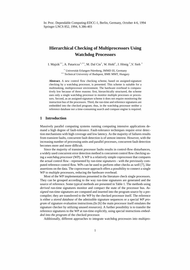
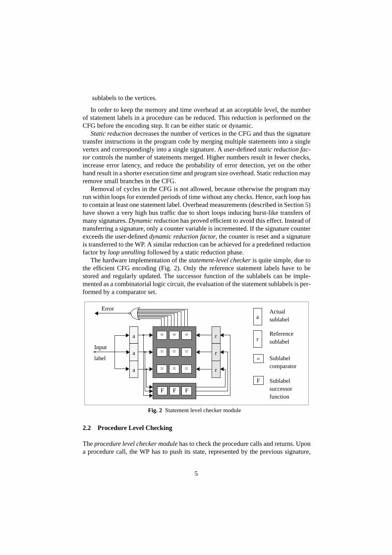
The hardware implementation of the statement-level checker is quite simple, due tothe efficient CFG encoding (Fig. 2). Only the reference statement labels have to bestored and regularly updated. The successor function of the sublabels can be imple-mented as a combinatorial logic circuit, the evaluation of the statement sublabels is per-formed by a comparator set.
2.2 Procedure Level Checking
The procedure level checker module has to check the procedure calls and returns. Upona procedure call, the WP has to push its state, represented by the previous signature,
F F F
= =
=
=
= =
=
= =
a
a
a
r
r
r
=
Error
F Sublabelsuccessorfunction
Sublabelcomparator
aActualsublabel
Referencesublabelr
Fig. 2 Statement level checker module
Input
label

6
onto its stack (called the signature stack), upon return, the latest signature has to bepopped from the stack.
Procedure calls are potentially data-dependent (e.g. procedure calls through vari-ables) in high level languages. Neither the location of the procedure call nor the calledprocedure can be identified by the precompiler in the CFG extraction step. Hence pro-cedure calls are allowed at any location of the program, independently of the actual in-struction structure. This way function calls embedded into arithmetic expressions andinterrupt handler routines can be checked in the same way as procedure calls. The dis-advantage is that only the returns from procedures can be checked, i.e. a wrong proce-dure call will be detected only after a long latency. Nonetheless, procedure calls areallowed to start only at an entry point of a procedure, so only an erroneous jump to thestarting point of a procedure can not be detected immediately.
The first and last statement labels of the procedures are marked by flags: Start of Pro-cedure (SOP) and End of Procedure (EOP), respectively. SOP means that the WP hasto push the actual reference onto the stack and the actual statement label is valid as thefirst reference of the called procedure. In case of EOP the statement label has to be val-idated by the statement label checker and the next reference has to be popped from thestack (the reference of the calling procedure).
The procedures of a program are numbered and their identifiers are embedded intothe signatures, together with the statement labels. Procedure IDs are allowed to changeonly if the SOP flag is set.
In a multi-tasking environment the WP and the signature stack storage is shared be-tween different processes. Signature stack areas can be either statically or dynamicallyallocated. Static allocation is uneconomical if there are “hyperactive” (e.g. recursive)processes needing more stack space, while others hardly use the stack. In the case of thedynamical allocation strategy the individual stacks are parts of a single global stack areaimplemented as a linked list. Each process stack is defined by a pointer as a header of alinked list. Cells of a stack can be linked to and from a global free list consisting of thewhole unused area. Thus, the stack area of a single process is limited only by the globalnumber of free cells and the activity of the other processes.
The procedure-level hardware checker module consists of the comparator for proce-dure IDs and the stack maintenance control. The size of the signature stack storage de-pends on the number of admissible embedded procedure calls. In the case of a stackoverflow its content is stored into its virtual extension in the main memory or in a stablestorage, from where the stack can be reloaded after becoming empty.
2.3 Process Level Checking
The process level module checks the scheduling of application processes running on thesame processor and the interaction of different processes, i.e. synchronization. Signa-ture transfer times are monitored by a timer and can be used to detect a hung system.
Checking of Process Scheduling. A unique ID is assigned to each application process.A processor-process database is established in the process level checker module of theWP: each processor has a record in this database storing the ID of the presently running

7
process. If the operating system schedules a new process on a processor then the corre-sponding record is replaced by the new process ID. The process and processor IDs areembedded into the signature; thus, the WP can compare them with the record in the pro-cessor-process database, allowing only correctly scheduled processes to be active.
Signature transfers are monitored process-wise by separate logical time-out checkersin the WP activated by the scheduler. All time-out checks share the same physical timerof the WP.
Checking of Process Interaction. One major goal of the research was the extension ofcontrol flow checking to the level of interprocess cooperation. Such checks allow theblocking of the dissemination of error effects from a faulty process to the other ones. Inthis way the error latency and losses in computation time can be drastically reduced. Forthis reason a skeleton-like description of the communication and synchronization struc-ture is required. Synchronization of application processes can be described e.g. by usinga simple CCS-like process algebra [14], (Appendix).
The basic idea will be illustrated by the simplest case, the synchronous communica-tion between two processes. This kind of communication is valid, if the sender processcloses it after the receiver process has accepted the data, and the receiver can not getdata before the sender begins the communication. An error is detected if one of the part-ner processes has already finished the communication and the other partner has not evenstarted it. Similarly to the lower levels checks, the WP will be notified on the status ofthe interprocess control flow by special signatures. Reference labels are assigned to thedifferent phases of the individual processes in order to make their state in the controlflow during the interaction observable for the WP. Such a reference label should changeonly after a synchronization in order to distinguish the different phases during the co-operation. (It can be shown that only the synchronization statements must be guardedby special signatures).
The informal description of the checking mechanism is as follows: during the syn-chronisation of two processes two special signatures are sent by each process.
1. The first, initializing signature before the execution of the synchronization notifiesthe WP, with which partner process the synchronization is intended. In case oferror-free operation, the other process will send a similar signature referring to thefirst process prior of the synchronization. Based on the initialization signatures ofthe participating processes the WP internally generates a common reference signa-ture for both of them.
2. The second signature is sent during the synchronization itself by each participatingprocess. It contains the reference signature for the partners, computed at compila-tion time in the same way as the WP handles the initialization signatures. This sec-ond signature is valid only if the partner processes coincide with the expected ones,and both processes have already initialized the synchronization, otherwise an erroris detected.
A register (called reference register) is reserved for each process internally in theWP. The synchronization checker module executes two operations depending on the ac-tually received guard signature:

8
1. Initialization. The initializing signatures before the statement of synchronizationcontain the ID of the presently running process and the ID of the intended partnerfor communication. When receiving this type of signature, the WP checker moduleexamines the reference register of the partner process. If the reference register doesnot contain the ID of the running process, than the process is the one beginning thesynchronization and the partner is uninitialized. To indicate this, the checker mod-ule stores the ID of the partner in the reference register of the running process (uni-directional, actual → partner process initialization).However, if the reference register of the partner already contains the ID of the run-ning process, the partner is ready for the synchronization due to the processing of aprevious signature. The initialization can be finished. The WP stores in both refer-ence registers the same reference label identifying the pair of partner processes(e.g. by some function of the process ID bits). This indicates that the communica-tion is allowed and the partners are ready for it.
2. Checking: The second guard signature (after the synchronization statement) trans-fers the synchronization label, which was computed by the precompiler using thesame function as the one used internally in the WP for the generation of the refer-ence label. The WP checker module compares this label with the content of the ref-erence register computed during the initialization step. Upon a mismatch an errorexception is raised.
In order to support the checking mechanism above, the precompiler has to parse theprogram text to identify the processes to be synchronized at a given statement, generatethe initializing signatures and the synchronization labels.
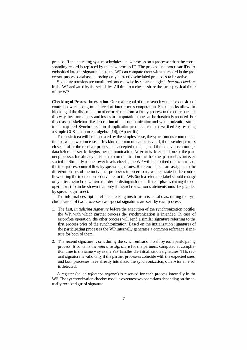
The examples in Table 2 present the insertion of guard signatures for synchronouscommunication (the sender has to wait for the receiver) and fork-join structures. The
Example Checked process systema Remark
Communication(synchronization) I(A,B).data.C(A⊗B).Ps |
I(B,A).data.C(B⊗A).Pr
A, B: process IDs
Ps: sender (cont’d)
Pr: receiver (cont’d)Sender Receiver
data.Ps data.Pr
Single fork (without join)I(A,B).fork.Pp |
fork.I(B,A).C(A⊗B).Pc
A,B: defined values
Pp: parent (cont’d)
Pc: child activities
Parent Child
fork.Pp fork.Pc
Fork-join structureI(A,B).fork.exit.I(A,B).C(A⊗B).Pp |fork.I(B,A).C(B⊗A).Pc.I(B,A).exit.0
A,B: defined values
Pp: parent (cont’d)
Pc: child activities
Parent Child
fork.exit.Pp fork.Pc.exit.0
a I(A,B) means that the process initializes the checking with A as actual and B as partnerlabel.C(A⊗B) means the initialization of the checking of label A⊗B using the reference label.
Table 2 Checking of the synchronization
9
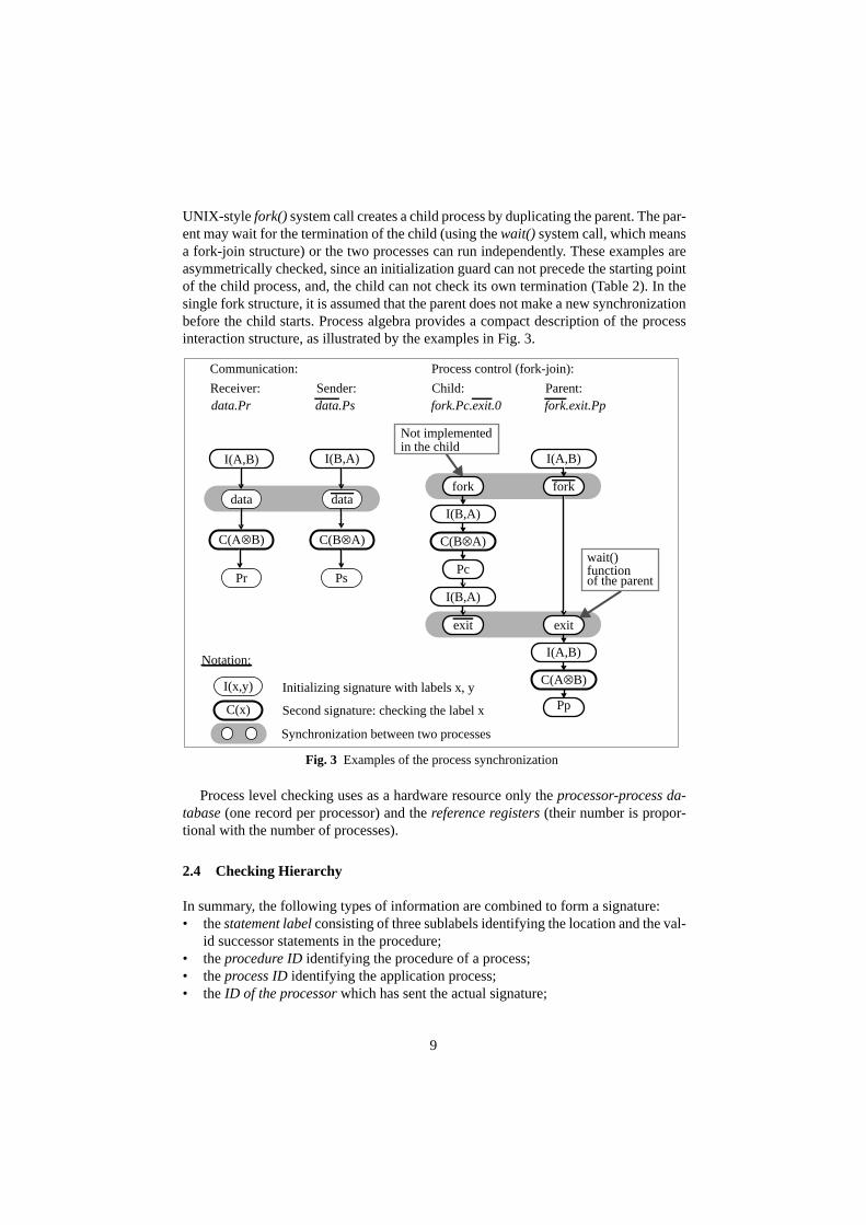
UNIX-style fork() system call creates a child process by duplicating the parent. The par-ent may wait for the termination of the child (using the wait() system call, which meansa fork-join structure) or the two processes can run independently. These examples areasymmetrically checked, since an initialization guard can not precede the starting pointof the child process, and, the child can not check its own termination (Table 2). In thesingle fork structure, it is assumed that the parent does not make a new synchronizationbefore the child starts. Process algebra provides a compact description of the processinteraction structure, as illustrated by the examples in Fig. 3.
Process level checking uses as a hardware resource only the processor-process da-tabase (one record per processor) and the reference registers (their number is propor-tional with the number of processes).
2.4 Checking Hierarchy
In summary, the following types of information are combined to form a signature:• the statement label consisting of three sublabels identifying the location and the val-
id successor statements in the procedure;• the procedure ID identifying the procedure of a process;• the process ID identifying the application process;• the ID of the processor which has sent the actual signature;
Fig. 3 Examples of the process synchronization
Notation:
I(x,y) Initializing signature with labels x, y
Synchronization between two processes
Communication:
C(x) Second signature: checking the label x
I(A,B) I(B,A)
C(Α⊗B) C(B⊗A)
data
data.Pr data.Ps
data
I(A,B)
exitexit
fork.Pc.exit.0 fork.exit.PpReceiver: Sender: Child: Parent:
Process control (fork-join):
fork
Pp
C(A⊗B)
I(A,B)
I(B,A)
C(B⊗A)
I(B,A)
Pcwait()
of the parentfunction
Not implementedin the child
Pr Ps
fork

10
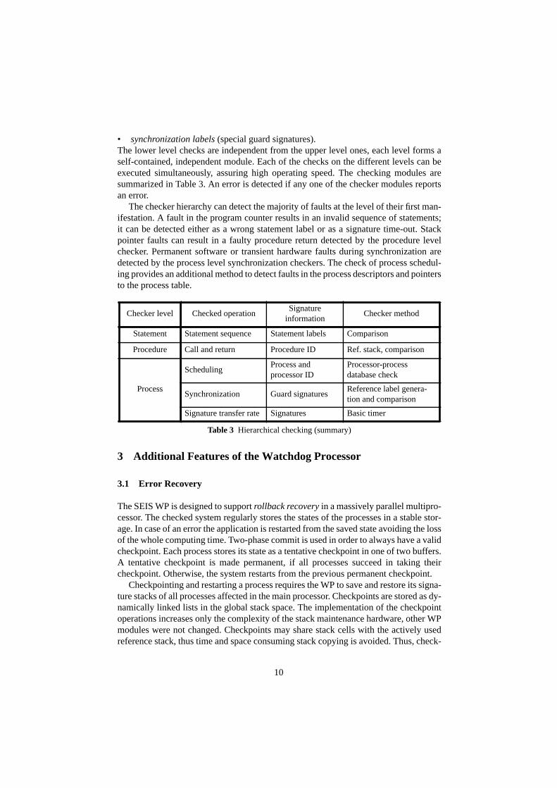
• synchronization labels (special guard signatures).The lower level checks are independent from the upper level ones, each level forms aself-contained, independent module. Each of the checks on the different levels can beexecuted simultaneously, assuring high operating speed. The checking modules aresummarized in Table 3. An error is detected if any one of the checker modules reportsan error.
The checker hierarchy can detect the majority of faults at the level of their first man-ifestation. A fault in the program counter results in an invalid sequence of statements;it can be detected either as a wrong statement label or as a signature time-out. Stackpointer faults can result in a faulty procedure return detected by the procedure levelchecker. Permanent software or transient hardware faults during synchronization aredetected by the process level synchronization checkers. The check of process schedul-ing provides an additional method to detect faults in the process descriptors and pointersto the process table.
3 Additional Features of the Watchdog Processor
3.1 Error Recovery
The SEIS WP is designed to support rollback recovery in a massively parallel multipro-cessor. The checked system regularly stores the states of the processes in a stable stor-age. In case of an error the application is restarted from the saved state avoiding the lossof the whole computing time. Two-phase commit is used in order to always have a validcheckpoint. Each process stores its state as a tentative checkpoint in one of two buffers.A tentative checkpoint is made permanent, if all processes succeed in taking theircheckpoint. Otherwise, the system restarts from the previous permanent checkpoint.
Checkpointing and restarting a process requires the WP to save and restore its signa-ture stacks of all processes affected in the main processor. Checkpoints are stored as dy-namically linked lists in the global stack space. The implementation of the checkpointoperations increases only the complexity of the stack maintenance hardware, other WPmodules were not changed. Checkpoints may share stack cells with the actively usedreference stack, thus time and space consuming stack copying is avoided. Thus, check-
Checker level Checked operationSignature
informationChecker method
Statement Statement sequence Statement labels Comparison
Procedure Call and return Procedure ID Ref. stack, comparison
Process
SchedulingProcess andprocessor ID
Processor-processdatabase check
Synchronization Guard signaturesReference label genera-tion and comparison
Signature transfer rate Signatures Basic timer
Table 3 Hierarchical checking (summary)
11
pointing only requires saving the operational stack pointer, and write-protecting the ref-erence stack. After an EOP signature labelling a return statement from a subroutine, awrite-protected stack cell is not linked to the free list, but remains part of the checkpointspace. Thus, the internal checkpoint operations of the WP can be executed in a pre-defined time independent from the stack depth of the process. The following operationsare supported:• Generation of a tentative checkpoint: The previous tentative checkpoint in the WP
is replaced by the actual reference signature stack of the process.• Commitment: The tentative checkpoint in the WP is made permanent.• Roll-back recovery: The operational reference signature stack of the process is re-
placed by the permanent checkpoint.The WP executes these operations internally initiated by corresponding special com-
mands embedded in the signature flow.
3.2 Error Notification
If an error is detected by a checker module of the WP, an error status word is generatedand the checked system is alarmed by an interrupt. The error status word is the concat-enation of the results of the different checker modules. An internal status FIFO is usedin the WP in order to avoid error signal overruns.
4 Integration of an Experimental SEIS WP into a Multiprocessor
4.1 The MEMSY Multiprocessor
The MEMSY multiprocessor developed at the University of Erlangen-Nürnberg has a2-level hierarchical, scalable regular structure with distributed locally shared commu-nication memory. The processing nodes at each level form a four-neighbor toroidalmesh coupled by multiport memories. Locally shared memory modules allow commu-nication of two neighboring nodes with the help of an interrupt network. This commu-nication memory is mapped into the address range of the processors and interfacedthrough dedicated buses.The basic building block of the MEMSY architecture is an el-ementary pyramid consisting of one higher level node supervising four lower levelnodes. Each computing node is a multiprocessor itself, containing four MC88100 RISCprocessors with the corresponding cache and MMU chips. The processor modules areoff-the-shelf highly integrated boards; so the instruction bus of the processors is not ob-servable for the purposes of derived signature generation without drastic hardwaremodifications.
Each basic pyramid of MEMSY is checked by a single WP in order to reduce thehardware overhead. Thus, the WP is able to check simultaneously 5 computing nodesconsisting of a total of 20 processors and running a maximum of 1280 processes [10].

12
4.2 Signature Transfer
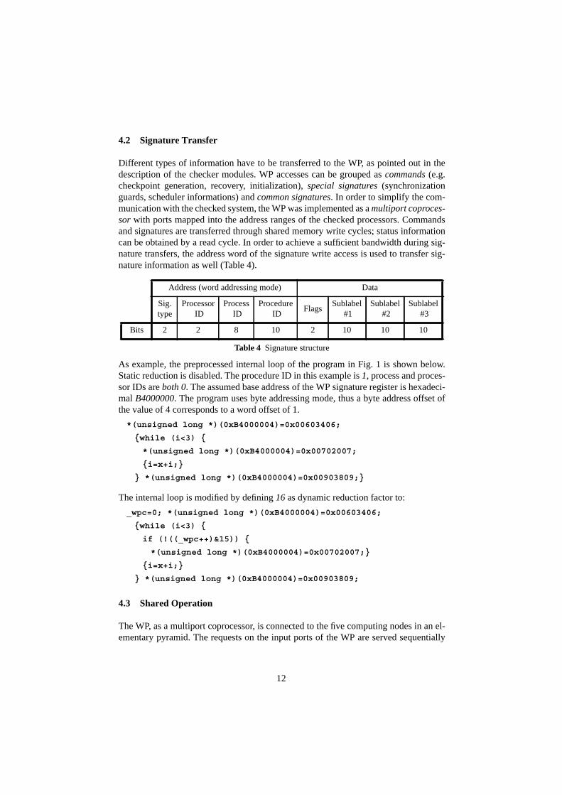
Different types of information have to be transferred to the WP, as pointed out in thedescription of the checker modules. WP accesses can be grouped as commands (e.g.checkpoint generation, recovery, initialization), special signatures (synchronizationguards, scheduler informations) and common signatures. In order to simplify the com-munication with the checked system, the WP was implemented as a multiport coproces-sor with ports mapped into the address ranges of the checked processors. Commandsand signatures are transferred through shared memory write cycles; status informationcan be obtained by a read cycle. In order to achieve a sufficient bandwidth during sig-nature transfers, the address word of the signature write access is used to transfer sig-nature information as well (Table 4).
As example, the preprocessed internal loop of the program in Fig. 1 is shown below.Static reduction is disabled. The procedure ID in this example is 1, process and proces-sor IDs are both 0. The assumed base address of the WP signature register is hexadeci-mal B4000000. The program uses byte addressing mode, thus a byte address offset ofthe value of 4 corresponds to a word offset of 1.
*(unsigned long *)(0xB4000004)=0x00603406;
{while (i<3) {
*(unsigned long *)(0xB4000004)=0x00702007;
{i=x+i;}
} *(unsigned long *)(0xB4000004)=0x00903809;}
The internal loop is modified by defining 16 as dynamic reduction factor to:
_wpc=0; *(unsigned long *)(0xB4000004)=0x00603406;
{while (i<3) {
if (!((_wpc++)&15)) {
*(unsigned long *)(0xB4000004)=0x00702007;}
{i=x+i;}
} *(unsigned long *)(0xB4000004)=0x00903809;
4.3 Shared Operation
The WP, as a multiport coprocessor, is connected to the five computing nodes in an el-ementary pyramid. The requests on the input ports of the WP are served sequentially
Address (word addressing mode) Data
Sig.type
Processor ID
Process ID
Procedure ID
FlagsSublabel
#1Sublabel
#2Sublabel
#3
Bits 2 2 8 10 2 10 10 10
Table 4 Signature structure
13
using a round-robin priority scheme. Signature checking is executed within a singlecommunication memory cycle. An input FIFO is used to smooth out the time overheadof the relatively complicated checkpoint operations and to avoid delays due to the time-shared use of the WP. Control operations, like initialization etc., are performed by thehigher level main processor node in an elementary MEMSY pyramid. All error reportsgenerated in the WP are copied to the higher level node, forming an error log of the en-tire basic pyramid.
4.4 MMU Utilization
As described earlier, the process ID field is embedded into the part of the signaturetransferred via the address bus. During preprocessing and compiling, the same constantvalues are assigned to all process ID fields in the statement labels, because these IDs areunavailable at compilation time. At run-time, depending on the process ID, the samevirtual address ranges are mapped by the MMU to different physical address ranges ofthe WP. Thus, the unrestricted use of shared code and shared libraries is supported.
In the MMU WP address sub-ranges can be defined as nonexistent or write-protect-ed. Only a single page corresponding to the process ID is visible in the user addressspace of a process preventing illegal accesses to the address range of other processes.Additionally, WP commands (e.g. checkpointing and recovery) are privileged, avoid-ing, for example, an accidental checkpoint overwrite.
4.5 Implementation Details
SEIS Precompiler. The current precompiler processes programs written in C language.The precompiler itself was written in C too, so it is fully portable to different platforms.For parsing bison is used, the encoding algorithm is a linear one.WP Hardware. The WP was implemented as a 16MHz coprocessor board on the VMEbus of the higher level node with interfaces to the four computing nodes on the lowerlevel identical with those used for the communication memory. WP operations (arbitra-tion, signature evaluation, stack handling and checkpointing) are controlled by 6MACH230 PLDs (3600 gate equivalent per device). The signature stack is in a 256KRAM block which proved to be oversized if no recursive programs were running. Syn-chronization checks were not used in the experimental version of the WP. Worst casesignature transfer and evaluation time is even in this moderate speed experimental ver-sion as low as 300-600 ns depending on the signature type and number of simultaneousrequests. Tentative checkpoint generation is executed in 2.3 microseconds.Operating System Modifications. The operating system of the checked computers wasonly slightly modified. Interrupt handlers serving the WP (e.g. detected error, saturationof the WP stack) have to be added to the system. The creation or scheduling of a newprocess requires the initialization of the internal WP processor-process database and theinitialization of the address translation tables in the MMU.

14
5 Measurement results
Standard benchmarks (like dhrystone, whetstone, linpack etc.) and scientific calcu-lation programs representing the expected typical MEMSY user profile (like a multigridbased solver of Poisson differential equations) were used for verification. Compilationwas done using gcc version 2.2.2 generating a highly optimized code. The followingcharacteristics were measured for each reduction strategy:• static code length;• fault coverage by injecting single bit transient errors into the program counter at a
single random phase of the program execution (5000 experiments were performedfor each individual case. The fault coverage was estimated with a relative error lessthan ±5% at a confidence level of 99%);
• program run times, using the system timer of MEMSY with a resolution of 10 msec;• number of signatures sent to the WP;• distribution of time between subsequent signature transfers in terms of number of
instructions executed by tracing the program in single-step mode.Naturally, the resulting characteristics show a dependency on the benchmark and on
the reduction method applied. However, the basic trends were essentially identical.Therefore, the following analysis of the measurement results is illustrated by the de-tailed results of the multigrid solver. The experiences with other benchmarks will bepresented as accumulated intervals.The overhead in code length varied between 20% and 85% in the general case depend-ing on the benchmark and static reduction factor. Results of the multigrid applicationare shown in Fig. 4. The number of signatures depends on the program size only ap-proximately linearly with a moderate coefficient. This overhead is affordable even forlarge programs in the Mbyte range. The efficiency of the static reduction rapidly dropswith a growing reduction factor. Our benchmark program consists typically of short
-----------Static reduction factor-------
0
50
100
150
200
250
Cod
e le
ngth
%
Original programLoop unrolling
Withoutsignatures
1 2 5 10
100%=4592 Bytes
Fig. 4 Static code length overhead
15
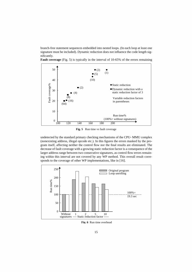
branch-free statement sequences embedded into nested loops. (In each loop at least onesignature must be included). Dynamic reduction does not influence the code length sig-nificantly.Fault coverage (Fig. 5) is typically in the interval of 10-65% of the errors remaining
undetected by the standard primary checking mechanisms of the CPU- MMU complex(nonexisting address, illegal opcode etc.). In this figures the errors masked by the pro-gram itself, affecting neither the control flow nor the final results are eliminated. Thedecrease of fault coverage with a growing static reduction factor is a consequence of thelarger address range between two consecutive signatures, as control flow errors remain-ing within this interval are not covered by any WP method. This overall result corre-sponds to the coverage of other WP implementations, like in [16].
Fig. 5 Run time vs fault coverage
100 120 140 160 180 200
Run time%
Faul
t cov
erag
e%
Dynamic reduction with a
Static reduction
static reduction factor of 3
Variable reduction factorsin parentheses
(1)(2)
(5)
(10)
(2)
(4)
(8)(16)
(64)
(100%= without signatures)0
10
20
30
40
50
100%=19.3 sec
0
50
100
150
200
250
Run
tim
e%
Original programLoop unrolling
signatures1 2 5 10Without
Fig. 6 Run time overhead
---- Static reduction factor -----

16
The run-time overhead increases drastically when using a small reduction factor, evento a level of 100% indicating a cumulative effect of multiple disadvantageous factors(Fig. 6). External bus cycles, like those required for signature transfer are by a factor of4 to 10 slower than a cache access [17]. If there are too few statements to execute be-tween two consecutive signatures, bus saturation can occur. In this case the CPU has towait for the end of the transfer inactivating its internal speedup mechanisms (instructionprefetch, pipelining). For a more detailed analysis the integrated distribution of time pe-riods between subsequent signature transfers was measured (Fig. 7).
In the ideal case, all signatures should be transferred within the same time period,defined by the user as a compromise between fault coverage and performance loss. Thefirst peak in the density function (Fig. 8) after only 3 instructions results in a lesser ex-tent from the unavoidable use of intermittent signatures in complex control structures.The dominating cause are overtested short loops, as a costly check is performed afteronly a few machine instructions. Dynamic reduction or loop unrolling with a subse-
0
10
20
30
40
50
60
70
80
0 5 10 15 20 25 30 35 40 45 50
Num
ber
of s
igna
ture
s (1
03 )
Without reduction
Dynamic: 2 + static: 3Unrolling + static: 5
Static: 10
Unrolling + static: 10
Dynamic: 16 +static: 3
Time (number of instructions)
Fig. 7 Integrated number of signature transfers
0
5
10
15
20
25
0 5 10 15 20 25 30
Num
ber
of s
igna
ture
s
Time (number of instructions)
Loop unrolling + static reduction by a factor of 5Original program
Fig. 8 Frequency density function of the time between signatures
17
quent static reduction (both puncturing signature transfers to each kth execution of theloop body) result in a radical reduction in run-time overhead without a drastic decreasein fault coverage. Undertesting can occur, even in the case of a single statement suchsimple as a=b, if a and b are complex data types involving a long copy operation.
Conclusion
The advantages and possible use of an assigned signature watchdog processor in mul-tiprocessor and multitasking environments were discussed. Main idea of the proposedSEIS method is the redundant encoding of the program CFG. In this way, only the lastsignature of each program block has to be stored as reference. The evaluation of the ac-tual signature is a simple combinatorial task. The advantages of the proposed methodsare the low hardware cost, the high processing speed and the easy integration into ex-isting systems. First experiments with the MEMSY multiprocessor yielded encouragingresults.
However, the traditional views on WPs based on high-level preprocessing, whichoriginate in the very first publications on this topic, must be revised in the light of themeasurement results. Beyond question, this approach remains attractive due to its out-standing advantages, like portability or compatibility with compiler-made automaticoptimization. Fault coverage corresponds approximately to the known methods at theassembly level. On the other hand, the rough granularity of individual statements doesnot allow a sufficiently fine tuning of the distribution of signature transfers in time. Thecurrent development aims at going deeper in the syntax hierarchy down to the elemen-tary operation level, where a similarly structured, but significantly more detailed CFGcan be built as at the instruction level. When weighting the edges of this CFG with theoperation execution times, the dynamic distribution of signature transfers reduces to aknown optimization problem. The WP can be further used without any modificationthanks to the very general and flexible nature of the encoding algorithm.
Appendix
The elements of the process algebra are defined as follows:• P,Q,... agents (representing the processes);• a,b,...∈L labels (representing observable operations e.g. receive a and send a, re-
spectively; 0 represents the end of the process);• α,β,...∈Act, (Act=L∪{τ}) actions (e.g. send, receive and the internal synchroniza-
tion τ).The expressions are composed with the help of three operators as prefix (., sequencingof actions), summation (+, non-deterministic choice) and composition (|, parallel exe-cution): P::=0α.PP+PP|P.

18
References
1 M. Dal Cin et al.: Fault Tolerance in Distributed Shared Memory Multiprocessors,in: A. Bode, M.Dal Cin (eds.), Parallel Computer Architectures, Lecture Notes inComputer Science 732, Berlin: Springer, pp. 31-48, 1993
2 J.B. Eifert, J.P. Shen: Processor Monitoring Using Asynchronous Signatured In-struction Streams. Proc. FTCS-14, 394-399 (1984)
3 F. Hofmann et al.: MEMSY - A Modular Expandable Multiprocessor System. In:A. Bode, M. Dal Cin (eds): Parallel Computer Architectures. Lecture Notes inComputer Science 732, Berlin: Springer, 1993, pp. 15-30
4 D.J. Lu: Watchdog Processors and Structural Integrity Checking. IEEE Trans. onComp. 31, 681-685 (1982)
5 H. Madeira et al.: A Watchdog Processor for Concurrent Error Detection in Multi-ple Processor Systems. Microprocessors and Microsystems 15, 123-131 (1991).
6 M. Schutte, J.P. Shen: Exploiting Instruction Level Resource Parallelism for Trans-parent Integrated Control-Flow Monitoring. Proc. FTCS-21, 318-325 (1991)
7 A. Mahmood, E.J. McCluskey.: Concurrent Error Detection Using Watchdog Proc-essors - A Survey. IEEE Transactions on Computers 37, 160-174 (1988)
8 T. Michel, R. Leveugle, G. Saucier: A New Approach to Control Flow CheckingWithout Program Modification. Proc. FTCS-21, 334-341 (1991)
9 E. Michel, W. Hohl: Concurrent Error Detection Using Watchdog Processors in theMultiprocessor System MEMSY. In: M. Dal Cin (ed): Fault Tolerant ComputingSystems. Informatik-Fachberichte 283. Berlin: Springer 1991, pp. 54-64
10 I. Majzik: Fault detection in the MEMSY multiprocessor using a SEIS watchdog-processor. Internal report 10/1993 of the IMMD3, Universität Erlangen, 1993
11 I. Majzik: SEIS: A program control-flow graph encoding algorithm for control flowchecking. Internal report, Technical University of Budapest, 1994 (in Press)
12 A. Pataricza, I. Majzik, W. Hohl, J. Hönig: Watchdog Processors in Parallel Sys-tems. Microprocessing and Microprogramming 39, 69-74 (1993)
13 J.P. Shen, S.P. Tomas: A Roving Monitoring Processor for Detection of ControlFlow Errors in Multiple Processor Systems. Microprocessing and Microprogram-ming 20, 249-269 (1987)
14 R. Milner: Communication and Concurrency. New York: Prentice Hall, 1989
15 T. Sridhar, S.M. Thatte: Concurrent Checking of Program Flow in VLSI Proces-sors. Proc. 1982 Int. Test Conf., 191-199 (1982)
16 G. Miremadi et al.: Two Software Techniques for On-Line Error Detection, ProcFTCS-22, 328-335 (1992)
17 J. Handy: The Cache Memory Handbook. San Diego: Academic Press 1993.

1
Hierarchical Checking of Multiprocessors UsingWatchdog Processors
I. Majzik++, A. Pataricza+,++, M. Dal Cin+, W. Hohl+, J. Hönig +,V. Sieh +
+ Universität Erlangen-Nürnberg, IMMD III, Germany++ Technical University of Budapest, BME MMT, Hungary
Abstract. A new control flow checking scheme, based on assigned-signaturechecking by a watchdog processor, is presented. This scheme is suitable for amultitasking, multiprocessor environment. The hardware overhead is compara-tively low because of three reasons: first, hierarchically structured, the schemeuses only a single watchdog processor to monitor multiple processes or proces-sors. Second, as an assigned-signature scheme it does not require monitoring theinstruction bus of the processors. Third, the run-time and reference signatures areembedded into the checked program; thus, in the watchdog processor neither areference database nor a time-consuming search and compare engine is required.
1 Introduction
Massively parallel computing systems running computing intensive applications de-mand a high degree of fault-tolerance. Fault-tolerance techniques require error detec-tion mechanisms with high coverage and low latency. As the majority of failures resultsfrom transient faults, concurrent fault detection is of utmost interest. However, with theincreasing number of processing units and parallel processes, concurrent fault detectionbecomes more and more difficult.
Since the majority of transient processor faults results in control-flow disturbances,a widely used concurrent error detection method is concurrent control flow checking us-ing a watchdog processor (WP). A WP is a relatively simple coprocessor that comparesthe actual control flow - represented by run-time signatures - with the previously com-puted reference control flow. WPs can be used to perform other checks as well [7], likeassertions on the data. The coprocessor-approach offers a possibility to connect a singleWP to multiple processors, reducing the hardware overhead.
Most of the WP implementations presented in the literature check single processors.They can be grouped according to the way run-time signatures are generated and thesource of reference. Some typical methods are presented in Table 1. The methods usingderived run-time signatures monitor and compact the state of the processor bus. As-signed run-time signatures are computed and inserted into the program source by a pre-compiler; they are transferred to the WP by the checked processor itself. The referenceis either a stored database of the admissible signature sequences or a special WP pro-gram of signature evaluation instructions.(In [6] the main processor itself emulates thesignature checker by utilizing unused resources). A further possibility is to transfer thereference signatures to the WP at run-time explicitly, using special instructions embed-ded into the program of the checked processor.
Additionally, different approaches to integrate watchdog processors into multipro-
In: Proc. Dependable Computing-EDCC-1, Berlin, Germany, October 4-6, 1994Springer LNCS 852, 1994, S.386-403
2
cessor systems are known: a Roving Monitoring Processor [13] is connected to multipleprocessors and monitors their states sequentially without checking their interactions.The Checker described in [5] stores the reference signatures in the local memory of theWP. The information on the control flow graph (CFG) is not stored, the admissible run-time signatures are identified by associative memory segments in the WP. Multiple pro-cessors are checked using signature queues.
A further WP method intended to be used in multiprocessors is Extended StructuralIntegrity Checking (ESIC [9]). Signatures are assigned based on the high-level lan-guage structure of the program and transferred to the WP explicitly. Reference signa-tures are downloaded to the WP in tabular form before the beginning of programexecution. The WP receives the run-time signatures and works as a finite deterministicstack automaton. In a multitasking environment, the WP always switches to the refer-ence table of the process a signature was received from.
The main drawback of these methods is the (over)proportional increase of hardwareand time overhead if more computing nodes and processes are added. Our paper pre-sents a novel program control-flow checking method and a corresponding WP architec-ture called Signature Encoded Instruction Stream (SEIS [12]). The design goals of theSEIS project were:• An efficient hierarchical checking method of multiple processors by a single WP.• Checking interactions between the processes of an application.• Reducing the hardware overhead by efficient utilization of the WP resources.
As up-to-date microprocessors have a built-in instruction pipeline and on-chip cachememory, the assigned signature method was chosen as the focus of interest. The exper-imental multiprocessor system MEMSY1 (Modular Expandable Multiprocessor System[1, 2]) was used as test-bed of the SEIS WP prototype.
The paper is structured as follows. The next section presents the checking schemesapplied on different levels of the target system covering both theoretical and hardwareaspects. The subsequent two sections describe additional features of the watchdog pro-cessor and the integration of the SEIS WP into the MEMSY multiprocessor, respective-ly. The last section presents measurement results and conclusions.
1. MEMSY was developed in the framework of the DFG project SFB 182. The research presentedhere was supported by the Hungarian-German Joint Scientific Research Project #70, Konrad ZuseProgram (DAAD), OTKA-3394 and F7414 (Hungarian NSF)
Reference
Stored signaturedatabase
Watchdogprogram
Embeddedsignatures
Run-timecontrol
flow
Derivedsignatures
AsynchronousSignatured Instruction
Stream [2]
Watchdog DirectProcessing [8]
Basic Path SignatureAnalysis [15]
Assignedsignatures
Extended StructuralIntegrity Checking [9]
Structural Integ-rity Checking [4]
Signature EncodedInstruction Stream [12]
Table 1 Control flow checking methods

3
2 Levels of Concurrent Error Detection
Our method is intended for use in multiprocessors with a UNIX-like operating system,widely used in massively parallel multiprocessors for scientific computations. An ap-plication consists of processes running the application program written in a proceduralprogramming language (e.g. C, Pascal). Programs contain procedures composed ofstatements. At each level (process, procedure and statement) a different checking meth-od and WP module is used.
2.1 Statement Level Checking
The execution sequence of statements in a program can be associated with a programcontrol flow graph (CFG). Vertices represent branch-free statement sequences, edgesrepresent the syntactically correct control flow between them. The CFG can be extract-ed by syntax analysis of the program source. Interrupts, data dependencies in condition-al branches, and procedure calls referenced by pointers raise special problems.Conditional branches allow typically two outgoing edges from a vertex, procedure callsmay call any other procedure, and interrupts, resulting in a call to an interrupt handlingprocedure, may occur at any time. The latter two problems belong to the procedure leveland are covered in the next subsection.
The statement level WP module checks the correct execution order of statements bycomparison with the corresponding paths in the CFG. In order to identify the state ofprogram execution, statement labels are assigned to the vertices of the CFG. These la-bels are explicitly transferred to the WP. The transfer instructions and the label valuesare inserted into the high level source text by a precompiler.
Statement labels identify not only the CFG vertices but their (syntactically) validsuccessor vertices as well. Thus, checking of the statement label sequence is based onlyon the presently checked label and its predecessor. This eliminates the need of a WP ref-erence database. Hence, the evaluation of the correctness of program flow is a simplecombinatorial task without any time consuming database search, allowing high speedprocessing. The label assignment algorithm of the precompiler is as follows (for a moreformal description see [11]):
1. The CFG of the procedure is extracted. The basic control structures form sub-graphs of the CFG. These subgraphs are identified according to the requirements ofthe encoding algorithm: that is, the number of successors of a vertex is limited inorder to reduce the information to be encoded in the label identifying them. Thesubgraphs are composed to form the CFG of a procedure.
2. The edges of the CFG are collected into an edge trail. The problem of edge collec-tion can be solved by well-known methods of Eulerian circuit generation.
3. A cyclic ordering of label values is defined and the edge trail is encoded. Adjacentvertices of the CFG are encoded by subsequent label values and different trails areseparated by unused sublabels. After encoding the trail, all labels corresponding tothe same vertex (called sublabels) are concatenated defining the statement label. In
4
this way a statement label is a valid successor of a reference label if and only if oneof its sublabels is successor of one of the sublabels of the reference label. This isthe basic rule of the statement label checking.Fig. 1 presents an example C program, its CFG and the corresponding sublabel set.Using the simplest, natural ordering of the sublabels, a sublabel j is a valid succes-sor of a reference sublabel i if and only if j=i+1. This rule is implemented by thesuccessor function F increasing the reference sublabel value by one. The statementlabel sequence during the execution of the program is valid if the subsequent state-ment labels have successor sublabels. In the example vertex d is a valid successorof vertex b, since F(2,5,2)=(3,6,3) and (6,13,6) have 6 as common sublabel.
4. Intermittent signatures are used in the encoding of special control structures with alarge number (>3) of successor or predecessor vertices. The number of such inter-mittent signatures (and the time overhead resulting from multiple signature trans-fers in a single vertex) is limited in a single signature per vertex by using a slightlymodified encoding algorithm. This is based on the reuse of identical sublabels indifferent vertices without introducing ambiguity in the encoding [11].Let assume that a case statement with an actual sublabel of 6 has more outputbranches than 3, the maximal number of successor vertices allowed by the basicencoding scheme. The sublabel 7 is assigned to each successor vertex, indicatingthat they all are valid successors of the case vertex. (Note, that no data dependen-cies, like branch selection, are checked by the WP). The individual output branchesof the case statement will be distinguished by assigning different second and third
a:for (j=0;j<2;j++){
b: if (x<0){
c: x=x+8;
}
else{
d: while (i<3){
e: i=x+i;
b
Program text Program control-flow graph Statement labels
Statement label set:
Vertex Sublabels Vertex Sublabels
a (16,1,1) e (7,8,7)
b (2,5,2) f (9,14,9)
c (3,3,3) g (4,10,4)
d (6,13,6) h (17,11,11)
Fig. 1 The encoding of the program control-flow graph
4104
787
1116
333
6136
9149
111117
252
d
a
c
fe
gh

5
sublabels to the vertices.
In order to keep the memory and time overhead at an acceptable level, the numberof statement labels in a procedure can be reduced. This reduction is performed on theCFG before the encoding step. It can be either static or dynamic.
Static reduction decreases the number of vertices in the CFG and thus the signaturetransfer instructions in the program code by merging multiple statements into a singlevertex and correspondingly into a single signature. A user-defined static reduction fac-tor controls the number of statements merged. Higher numbers result in fewer checks,increase error latency, and reduce the probability of error detection, yet on the otherhand result in a shorter execution time and program size overhead. Static reduction mayremove small branches in the CFG.
Removal of cycles in the CFG is not allowed, because otherwise the program mayrun within loops for extended periods of time without any checks. Hence, each loop hasto contain at least one statement label. Overhead measurements (described in Section 5)have shown a very high bus traffic due to short loops inducing burst-like transfers ofmany signatures. Dynamic reduction has proved efficient to avoid this effect. Instead oftransferring a signature, only a counter variable is incremented. If the signature counterexceeds the user-defined dynamic reduction factor, the counter is reset and a signatureis transferred to the WP. A similar reduction can be achieved for a predefined reductionfactor by loop unrolling followed by a static reduction phase.
The hardware implementation of the statement-level checker is quite simple, due tothe efficient CFG encoding (Fig. 2). Only the reference statement labels have to bestored and regularly updated. The successor function of the sublabels can be imple-mented as a combinatorial logic circuit, the evaluation of the statement sublabels is per-formed by a comparator set.
2.2 Procedure Level Checking
The procedure level checker module has to check the procedure calls and returns. Upona procedure call, the WP has to push its state, represented by the previous signature,
F F F
= =
=
=
= =
=
= =
a
a
a
r
r
r
=
Error
F Sublabelsuccessorfunction
Sublabelcomparator
aActualsublabel
Referencesublabelr
Fig. 2 Statement level checker module
Input
label
6
onto its stack (called the signature stack), upon return, the latest signature has to bepopped from the stack.
Procedure calls are potentially data-dependent (e.g. procedure calls through vari-ables) in high level languages. Neither the location of the procedure call nor the calledprocedure can be identified by the precompiler in the CFG extraction step. Hence pro-cedure calls are allowed at any location of the program, independently of the actual in-struction structure. This way function calls embedded into arithmetic expressions andinterrupt handler routines can be checked in the same way as procedure calls. The dis-advantage is that only the returns from procedures can be checked, i.e. a wrong proce-dure call will be detected only after a long latency. Nonetheless, procedure calls areallowed to start only at an entry point of a procedure, so only an erroneous jump to thestarting point of a procedure can not be detected immediately.
The first and last statement labels of the procedures are marked by flags: Start of Pro-cedure (SOP) and End of Procedure (EOP), respectively. SOP means that the WP hasto push the actual reference onto the stack and the actual statement label is valid as thefirst reference of the called procedure. In case of EOP the statement label has to be val-idated by the statement label checker and the next reference has to be popped from thestack (the reference of the calling procedure).
The procedures of a program are numbered and their identifiers are embedded intothe signatures, together with the statement labels. Procedure IDs are allowed to changeonly if the SOP flag is set.
In a multi-tasking environment the WP and the signature stack storage is shared be-tween different processes. Signature stack areas can be either statically or dynamicallyallocated. Static allocation is uneconomical if there are “hyperactive” (e.g. recursive)processes needing more stack space, while others hardly use the stack. In the case of thedynamical allocation strategy the individual stacks are parts of a single global stack areaimplemented as a linked list. Each process stack is defined by a pointer as a header of alinked list. Cells of a stack can be linked to and from a global free list consisting of thewhole unused area. Thus, the stack area of a single process is limited only by the globalnumber of free cells and the activity of the other processes.
The procedure-level hardware checker module consists of the comparator for proce-dure IDs and the stack maintenance control. The size of the signature stack storage de-pends on the number of admissible embedded procedure calls. In the case of a stackoverflow its content is stored into its virtual extension in the main memory or in a stablestorage, from where the stack can be reloaded after becoming empty.
2.3 Process Level Checking
The process level module checks the scheduling of application processes running on thesame processor and the interaction of different processes, i.e. synchronization. Signa-ture transfer times are monitored by a timer and can be used to detect a hung system.
Checking of Process Scheduling. A unique ID is assigned to each application process.A processor-process database is established in the process level checker module of theWP: each processor has a record in this database storing the ID of the presently running
7
process. If the operating system schedules a new process on a processor then the corre-sponding record is replaced by the new process ID. The process and processor IDs areembedded into the signature; thus, the WP can compare them with the record in the pro-cessor-process database, allowing only correctly scheduled processes to be active.
Signature transfers are monitored process-wise by separate logical time-out checkersin the WP activated by the scheduler. All time-out checks share the same physical timerof the WP.
Checking of Process Interaction. One major goal of the research was the extension ofcontrol flow checking to the level of interprocess cooperation. Such checks allow theblocking of the dissemination of error effects from a faulty process to the other ones. Inthis way the error latency and losses in computation time can be drastically reduced. Forthis reason a skeleton-like description of the communication and synchronization struc-ture is required. Synchronization of application processes can be described e.g. by usinga simple CCS-like process algebra [14], (Appendix).
The basic idea will be illustrated by the simplest case, the synchronous communica-tion between two processes. This kind of communication is valid, if the sender processcloses it after the receiver process has accepted the data, and the receiver can not getdata before the sender begins the communication. An error is detected if one of the part-ner processes has already finished the communication and the other partner has not evenstarted it. Similarly to the lower levels checks, the WP will be notified on the status ofthe interprocess control flow by special signatures. Reference labels are assigned to thedifferent phases of the individual processes in order to make their state in the controlflow during the interaction observable for the WP. Such a reference label should changeonly after a synchronization in order to distinguish the different phases during the co-operation. (It can be shown that only the synchronization statements must be guardedby special signatures).
The informal description of the checking mechanism is as follows: during the syn-chronisation of two processes two special signatures are sent by each process.
1. The first, initializing signature before the execution of the synchronization notifiesthe WP, with which partner process the synchronization is intended. In case oferror-free operation, the other process will send a similar signature referring to thefirst process prior of the synchronization. Based on the initialization signatures ofthe participating processes the WP internally generates a common reference signa-ture for both of them.
2. The second signature is sent during the synchronization itself by each participatingprocess. It contains the reference signature for the partners, computed at compila-tion time in the same way as the WP handles the initialization signatures. This sec-ond signature is valid only if the partner processes coincide with the expected ones,and both processes have already initialized the synchronization, otherwise an erroris detected.
A register (called reference register) is reserved for each process internally in theWP. The synchronization checker module executes two operations depending on the ac-tually received guard signature:
8
1. Initialization. The initializing signatures before the statement of synchronizationcontain the ID of the presently running process and the ID of the intended partnerfor communication. When receiving this type of signature, the WP checker moduleexamines the reference register of the partner process. If the reference register doesnot contain the ID of the running process, than the process is the one beginning thesynchronization and the partner is uninitialized. To indicate this, the checker mod-ule stores the ID of the partner in the reference register of the running process (uni-directional, actual → partner process initialization).However, if the reference register of the partner already contains the ID of the run-ning process, the partner is ready for the synchronization due to the processing of aprevious signature. The initialization can be finished. The WP stores in both refer-ence registers the same reference label identifying the pair of partner processes(e.g. by some function of the process ID bits). This indicates that the communica-tion is allowed and the partners are ready for it.
2. Checking: The second guard signature (after the synchronization statement) trans-fers the synchronization label, which was computed by the precompiler using thesame function as the one used internally in the WP for the generation of the refer-ence label. The WP checker module compares this label with the content of the ref-erence register computed during the initialization step. Upon a mismatch an errorexception is raised.
In order to support the checking mechanism above, the precompiler has to parse theprogram text to identify the processes to be synchronized at a given statement, generatethe initializing signatures and the synchronization labels.
The examples in Table 2 present the insertion of guard signatures for synchronouscommunication (the sender has to wait for the receiver) and fork-join structures. The
Example Checked process systema Remark
Communication(synchronization) I(A,B).data.C(A⊗B).Ps |
I(B,A).data.C(B⊗A).Pr
A, B: process IDs
Ps: sender (cont’d)
Pr: receiver (cont’d)Sender Receiver
data.Ps data.Pr
Single fork (without join)I(A,B).fork.Pp |
fork.I(B,A).C(A⊗B).Pc
A,B: defined values
Pp: parent (cont’d)
Pc: child activities
Parent Child
fork.Pp fork.Pc
Fork-join structureI(A,B).fork.exit.I(A,B).C(A⊗B).Pp |fork.I(B,A).C(B⊗A).Pc.I(B,A).exit.0
A,B: defined values
Pp: parent (cont’d)
Pc: child activities
Parent Child
fork.exit.Pp fork.Pc.exit.0
a I(A,B) means that the process initializes the checking with A as actual and B as partnerlabel.C(A⊗B) means the initialization of the checking of label A⊗B using the reference label.
Table 2 Checking of the synchronization

9
UNIX-style fork() system call creates a child process by duplicating the parent. The par-ent may wait for the termination of the child (using the wait() system call, which meansa fork-join structure) or the two processes can run independently. These examples areasymmetrically checked, since an initialization guard can not precede the starting pointof the child process, and, the child can not check its own termination (Table 2). In thesingle fork structure, it is assumed that the parent does not make a new synchronizationbefore the child starts. Process algebra provides a compact description of the processinteraction structure, as illustrated by the examples in Fig. 3.
Process level checking uses as a hardware resource only the processor-process da-tabase (one record per processor) and the reference registers (their number is propor-tional with the number of processes).
2.4 Checking Hierarchy
In summary, the following types of information are combined to form a signature:• the statement label consisting of three sublabels identifying the location and the val-
id successor statements in the procedure;• the procedure ID identifying the procedure of a process;• the process ID identifying the application process;• the ID of the processor which has sent the actual signature;
Fig. 3 Examples of the process synchronization
Notation:
I(x,y) Initializing signature with labels x, y
Synchronization between two processes
Communication:
C(x) Second signature: checking the label x
I(A,B) I(B,A)
C(Α⊗B) C(B⊗A)
data
data.Pr data.Ps
data
I(A,B)
exitexit
fork.Pc.exit.0 fork.exit.PpReceiver: Sender: Child: Parent:
Process control (fork-join):
fork
Pp
C(A⊗B)
I(A,B)
I(B,A)
C(B⊗A)
I(B,A)
Pcwait()
of the parentfunction
Not implementedin the child
Pr Ps
fork
10
• synchronization labels (special guard signatures).The lower level checks are independent from the upper level ones, each level forms aself-contained, independent module. Each of the checks on the different levels can beexecuted simultaneously, assuring high operating speed. The checking modules aresummarized in Table 3. An error is detected if any one of the checker modules reportsan error.
The checker hierarchy can detect the majority of faults at the level of their first man-ifestation. A fault in the program counter results in an invalid sequence of statements;it can be detected either as a wrong statement label or as a signature time-out. Stackpointer faults can result in a faulty procedure return detected by the procedure levelchecker. Permanent software or transient hardware faults during synchronization aredetected by the process level synchronization checkers. The check of process schedul-ing provides an additional method to detect faults in the process descriptors and pointersto the process table.
3 Additional Features of the Watchdog Processor
3.1 Error Recovery
The SEIS WP is designed to support rollback recovery in a massively parallel multipro-cessor. The checked system regularly stores the states of the processes in a stable stor-age. In case of an error the application is restarted from the saved state avoiding the lossof the whole computing time. Two-phase commit is used in order to always have a validcheckpoint. Each process stores its state as a tentative checkpoint in one of two buffers.A tentative checkpoint is made permanent, if all processes succeed in taking theircheckpoint. Otherwise, the system restarts from the previous permanent checkpoint.
Checkpointing and restarting a process requires the WP to save and restore its signa-ture stacks of all processes affected in the main processor. Checkpoints are stored as dy-namically linked lists in the global stack space. The implementation of the checkpointoperations increases only the complexity of the stack maintenance hardware, other WPmodules were not changed. Checkpoints may share stack cells with the actively usedreference stack, thus time and space consuming stack copying is avoided. Thus, check-
Checker level Checked operationSignature
informationChecker method
Statement Statement sequence Statement labels Comparison
Procedure Call and return Procedure ID Ref. stack, comparison
Process
SchedulingProcess andprocessor ID
Processor-processdatabase check
Synchronization Guard signaturesReference label genera-tion and comparison
Signature transfer rate Signatures Basic timer
Table 3 Hierarchical checking (summary)

11
pointing only requires saving the operational stack pointer, and write-protecting the ref-erence stack. After an EOP signature labelling a return statement from a subroutine, awrite-protected stack cell is not linked to the free list, but remains part of the checkpointspace. Thus, the internal checkpoint operations of the WP can be executed in a pre-defined time independent from the stack depth of the process. The following operationsare supported:• Generation of a tentative checkpoint: The previous tentative checkpoint in the WP
is replaced by the actual reference signature stack of the process.• Commitment: The tentative checkpoint in the WP is made permanent.• Roll-back recovery: The operational reference signature stack of the process is re-
placed by the permanent checkpoint.The WP executes these operations internally initiated by corresponding special com-
mands embedded in the signature flow.
3.2 Error Notification
If an error is detected by a checker module of the WP, an error status word is generatedand the checked system is alarmed by an interrupt. The error status word is the concat-enation of the results of the different checker modules. An internal status FIFO is usedin the WP in order to avoid error signal overruns.
4 Integration of an Experimental SEIS WP into a Multiprocessor
4.1 The MEMSY Multiprocessor
The MEMSY multiprocessor developed at the University of Erlangen-Nürnberg has a2-level hierarchical, scalable regular structure with distributed locally shared commu-nication memory. The processing nodes at each level form a four-neighbor toroidalmesh coupled by multiport memories. Locally shared memory modules allow commu-nication of two neighboring nodes with the help of an interrupt network. This commu-nication memory is mapped into the address range of the processors and interfacedthrough dedicated buses.The basic building block of the MEMSY architecture is an el-ementary pyramid consisting of one higher level node supervising four lower levelnodes. Each computing node is a multiprocessor itself, containing four MC88100 RISCprocessors with the corresponding cache and MMU chips. The processor modules areoff-the-shelf highly integrated boards; so the instruction bus of the processors is not ob-servable for the purposes of derived signature generation without drastic hardwaremodifications.
Each basic pyramid of MEMSY is checked by a single WP in order to reduce thehardware overhead. Thus, the WP is able to check simultaneously 5 computing nodesconsisting of a total of 20 processors and running a maximum of 1280 processes [10].
12
4.2 Signature Transfer
Different types of information have to be transferred to the WP, as pointed out in thedescription of the checker modules. WP accesses can be grouped as commands (e.g.checkpoint generation, recovery, initialization), special signatures (synchronizationguards, scheduler informations) and common signatures. In order to simplify the com-munication with the checked system, the WP was implemented as a multiport coproces-sor with ports mapped into the address ranges of the checked processors. Commandsand signatures are transferred through shared memory write cycles; status informationcan be obtained by a read cycle. In order to achieve a sufficient bandwidth during sig-nature transfers, the address word of the signature write access is used to transfer sig-nature information as well (Table 4).
As example, the preprocessed internal loop of the program in Fig. 1 is shown below.Static reduction is disabled. The procedure ID in this example is 1, process and proces-sor IDs are both 0. The assumed base address of the WP signature register is hexadeci-mal B4000000. The program uses byte addressing mode, thus a byte address offset ofthe value of 4 corresponds to a word offset of 1.
*(unsigned long *)(0xB4000004)=0x00603406;
{while (i<3) {
*(unsigned long *)(0xB4000004)=0x00702007;
{i=x+i;}
} *(unsigned long *)(0xB4000004)=0x00903809;}
The internal loop is modified by defining 16 as dynamic reduction factor to:
_wpc=0; *(unsigned long *)(0xB4000004)=0x00603406;
{while (i<3) {
if (!((_wpc++)&15)) {
*(unsigned long *)(0xB4000004)=0x00702007;}
{i=x+i;}
} *(unsigned long *)(0xB4000004)=0x00903809;
4.3 Shared Operation
The WP, as a multiport coprocessor, is connected to the five computing nodes in an el-ementary pyramid. The requests on the input ports of the WP are served sequentially
Address (word addressing mode) Data
Sig.type
Processor ID
Process ID
Procedure ID
FlagsSublabel
#1Sublabel
#2Sublabel
#3
Bits 2 2 8 10 2 10 10 10
Table 4 Signature structure

13
using a round-robin priority scheme. Signature checking is executed within a singlecommunication memory cycle. An input FIFO is used to smooth out the time overheadof the relatively complicated checkpoint operations and to avoid delays due to the time-shared use of the WP. Control operations, like initialization etc., are performed by thehigher level main processor node in an elementary MEMSY pyramid. All error reportsgenerated in the WP are copied to the higher level node, forming an error log of the en-tire basic pyramid.
4.4 MMU Utilization
As described earlier, the process ID field is embedded into the part of the signaturetransferred via the address bus. During preprocessing and compiling, the same constantvalues are assigned to all process ID fields in the statement labels, because these IDs areunavailable at compilation time. At run-time, depending on the process ID, the samevirtual address ranges are mapped by the MMU to different physical address ranges ofthe WP. Thus, the unrestricted use of shared code and shared libraries is supported.
In the MMU WP address sub-ranges can be defined as nonexistent or write-protect-ed. Only a single page corresponding to the process ID is visible in the user addressspace of a process preventing illegal accesses to the address range of other processes.Additionally, WP commands (e.g. checkpointing and recovery) are privileged, avoid-ing, for example, an accidental checkpoint overwrite.
4.5 Implementation Details
SEIS Precompiler. The current precompiler processes programs written in C language.The precompiler itself was written in C too, so it is fully portable to different platforms.For parsing bison is used, the encoding algorithm is a linear one.WP Hardware. The WP was implemented as a 16MHz coprocessor board on the VMEbus of the higher level node with interfaces to the four computing nodes on the lowerlevel identical with those used for the communication memory. WP operations (arbitra-tion, signature evaluation, stack handling and checkpointing) are controlled by 6MACH230 PLDs (3600 gate equivalent per device). The signature stack is in a 256KRAM block which proved to be oversized if no recursive programs were running. Syn-chronization checks were not used in the experimental version of the WP. Worst casesignature transfer and evaluation time is even in this moderate speed experimental ver-sion as low as 300-600 ns depending on the signature type and number of simultaneousrequests. Tentative checkpoint generation is executed in 2.3 microseconds.Operating System Modifications. The operating system of the checked computers wasonly slightly modified. Interrupt handlers serving the WP (e.g. detected error, saturationof the WP stack) have to be added to the system. The creation or scheduling of a newprocess requires the initialization of the internal WP processor-process database and theinitialization of the address translation tables in the MMU.
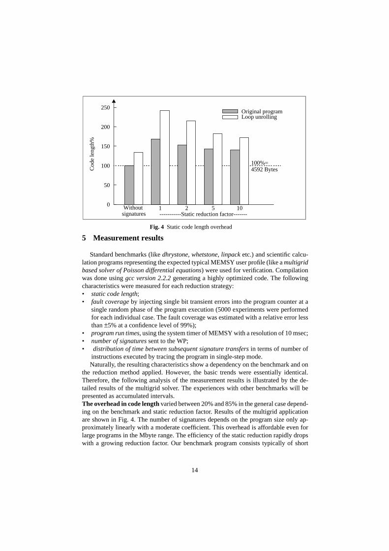
14
5 Measurement results
Standard benchmarks (like dhrystone, whetstone, linpack etc.) and scientific calcu-lation programs representing the expected typical MEMSY user profile (like a multigridbased solver of Poisson differential equations) were used for verification. Compilationwas done using gcc version 2.2.2 generating a highly optimized code. The followingcharacteristics were measured for each reduction strategy:• static code length;• fault coverage by injecting single bit transient errors into the program counter at a
single random phase of the program execution (5000 experiments were performedfor each individual case. The fault coverage was estimated with a relative error lessthan ±5% at a confidence level of 99%);
• program run times, using the system timer of MEMSY with a resolution of 10 msec;• number of signatures sent to the WP;• distribution of time between subsequent signature transfers in terms of number of
instructions executed by tracing the program in single-step mode.Naturally, the resulting characteristics show a dependency on the benchmark and on
the reduction method applied. However, the basic trends were essentially identical.Therefore, the following analysis of the measurement results is illustrated by the de-tailed results of the multigrid solver. The experiences with other benchmarks will bepresented as accumulated intervals.The overhead in code length varied between 20% and 85% in the general case depend-ing on the benchmark and static reduction factor. Results of the multigrid applicationare shown in Fig. 4. The number of signatures depends on the program size only ap-proximately linearly with a moderate coefficient. This overhead is affordable even forlarge programs in the Mbyte range. The efficiency of the static reduction rapidly dropswith a growing reduction factor. Our benchmark program consists typically of short
-----------Static reduction factor-------
0
50
100
150
200
250
Cod
e le
ngth
%
Original programLoop unrolling
Withoutsignatures
1 2 5 10
100%=4592 Bytes
Fig. 4 Static code length overhead

15
branch-free statement sequences embedded into nested loops. (In each loop at least onesignature must be included). Dynamic reduction does not influence the code length sig-nificantly.Fault coverage (Fig. 5) is typically in the interval of 10-65% of the errors remaining
undetected by the standard primary checking mechanisms of the CPU- MMU complex(nonexisting address, illegal opcode etc.). In this figures the errors masked by the pro-gram itself, affecting neither the control flow nor the final results are eliminated. Thedecrease of fault coverage with a growing static reduction factor is a consequence of thelarger address range between two consecutive signatures, as control flow errors remain-ing within this interval are not covered by any WP method. This overall result corre-sponds to the coverage of other WP implementations, like in [16].
Fig. 5 Run time vs fault coverage
100 120 140 160 180 200
Run time%
Faul
t cov
erag
e%
Dynamic reduction with a
Static reduction
static reduction factor of 3
Variable reduction factorsin parentheses
(1)(2)
(5)
(10)
(2)
(4)
(8)(16)
(64)
(100%= without signatures)0
10
20
30
40
50
100%=19.3 sec
0
50
100
150
200
250
Run
tim
e%
Original programLoop unrolling
signatures1 2 5 10Without
Fig. 6 Run time overhead
---- Static reduction factor -----
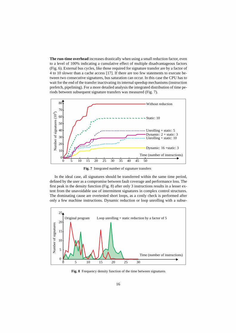
16
The run-time overhead increases drastically when using a small reduction factor, evento a level of 100% indicating a cumulative effect of multiple disadvantageous factors(Fig. 6). External bus cycles, like those required for signature transfer are by a factor of4 to 10 slower than a cache access [17]. If there are too few statements to execute be-tween two consecutive signatures, bus saturation can occur. In this case the CPU has towait for the end of the transfer inactivating its internal speedup mechanisms (instructionprefetch, pipelining). For a more detailed analysis the integrated distribution of time pe-riods between subsequent signature transfers was measured (Fig. 7).
In the ideal case, all signatures should be transferred within the same time period,defined by the user as a compromise between fault coverage and performance loss. Thefirst peak in the density function (Fig. 8) after only 3 instructions results in a lesser ex-tent from the unavoidable use of intermittent signatures in complex control structures.The dominating cause are overtested short loops, as a costly check is performed afteronly a few machine instructions. Dynamic reduction or loop unrolling with a subse-
0
10
20
30
40
50
60
70
80
0 5 10 15 20 25 30 35 40 45 50
Num
ber
of s
igna
ture
s (1
03 )
Without reduction
Dynamic: 2 + static: 3Unrolling + static: 5
Static: 10
Unrolling + static: 10
Dynamic: 16 +static: 3
Time (number of instructions)
Fig. 7 Integrated number of signature transfers
0
5
10
15
20
25
0 5 10 15 20 25 30
Num
ber
of s
igna
ture
s
Time (number of instructions)
Loop unrolling + static reduction by a factor of 5Original program
Fig. 8 Frequency density function of the time between signatures

17
quent static reduction (both puncturing signature transfers to each kth execution of theloop body) result in a radical reduction in run-time overhead without a drastic decreasein fault coverage. Undertesting can occur, even in the case of a single statement suchsimple as a=b, if a and b are complex data types involving a long copy operation.
Conclusion
The advantages and possible use of an assigned signature watchdog processor in mul-tiprocessor and multitasking environments were discussed. Main idea of the proposedSEIS method is the redundant encoding of the program CFG. In this way, only the lastsignature of each program block has to be stored as reference. The evaluation of the ac-tual signature is a simple combinatorial task. The advantages of the proposed methodsare the low hardware cost, the high processing speed and the easy integration into ex-isting systems. First experiments with the MEMSY multiprocessor yielded encouragingresults.
However, the traditional views on WPs based on high-level preprocessing, whichoriginate in the very first publications on this topic, must be revised in the light of themeasurement results. Beyond question, this approach remains attractive due to its out-standing advantages, like portability or compatibility with compiler-made automaticoptimization. Fault coverage corresponds approximately to the known methods at theassembly level. On the other hand, the rough granularity of individual statements doesnot allow a sufficiently fine tuning of the distribution of signature transfers in time. Thecurrent development aims at going deeper in the syntax hierarchy down to the elemen-tary operation level, where a similarly structured, but significantly more detailed CFGcan be built as at the instruction level. When weighting the edges of this CFG with theoperation execution times, the dynamic distribution of signature transfers reduces to aknown optimization problem. The WP can be further used without any modificationthanks to the very general and flexible nature of the encoding algorithm.
Appendix
The elements of the process algebra are defined as follows:• P,Q,... agents (representing the processes);• a,b,...∈L labels (representing observable operations e.g. receive a and send a, re-
spectively; 0 represents the end of the process);• α,β,...∈Act, (Act=L∪{τ}) actions (e.g. send, receive and the internal synchroniza-
tion τ).The expressions are composed with the help of three operators as prefix (., sequencingof actions), summation (+, non-deterministic choice) and composition (|, parallel exe-cution): P::=0α.PP+PP|P.
18
References
1 M. Dal Cin et al.: Fault Tolerance in Distributed Shared Memory Multiprocessors,in: A. Bode, M.Dal Cin (eds.), Parallel Computer Architectures, Lecture Notes inComputer Science 732, Berlin: Springer, pp. 31-48, 1993
2 J.B. Eifert, J.P. Shen: Processor Monitoring Using Asynchronous Signatured In-struction Streams. Proc. FTCS-14, 394-399 (1984)
3 F. Hofmann et al.: MEMSY - A Modular Expandable Multiprocessor System. In:A. Bode, M. Dal Cin (eds): Parallel Computer Architectures. Lecture Notes inComputer Science 732, Berlin: Springer, 1993, pp. 15-30
4 D.J. Lu: Watchdog Processors and Structural Integrity Checking. IEEE Trans. onComp. 31, 681-685 (1982)
5 H. Madeira et al.: A Watchdog Processor for Concurrent Error Detection in Multi-ple Processor Systems. Microprocessors and Microsystems 15, 123-131 (1991).
6 M. Schutte, J.P. Shen: Exploiting Instruction Level Resource Parallelism for Trans-parent Integrated Control-Flow Monitoring. Proc. FTCS-21, 318-325 (1991)
7 A. Mahmood, E.J. McCluskey.: Concurrent Error Detection Using Watchdog Proc-essors - A Survey. IEEE Transactions on Computers 37, 160-174 (1988)
8 T. Michel, R. Leveugle, G. Saucier: A New Approach to Control Flow CheckingWithout Program Modification. Proc. FTCS-21, 334-341 (1991)
9 E. Michel, W. Hohl: Concurrent Error Detection Using Watchdog Processors in theMultiprocessor System MEMSY. In: M. Dal Cin (ed): Fault Tolerant ComputingSystems. Informatik-Fachberichte 283. Berlin: Springer 1991, pp. 54-64
10 I. Majzik: Fault detection in the MEMSY multiprocessor using a SEIS watchdog-processor. Internal report 10/1993 of the IMMD3, Universität Erlangen, 1993
11 I. Majzik: SEIS: A program control-flow graph encoding algorithm for control flowchecking. Internal report, Technical University of Budapest, 1994 (in Press)
12 A. Pataricza, I. Majzik, W. Hohl, J. Hönig: Watchdog Processors in Parallel Sys-tems. Microprocessing and Microprogramming 39, 69-74 (1993)
13 J.P. Shen, S.P. Tomas: A Roving Monitoring Processor for Detection of ControlFlow Errors in Multiple Processor Systems. Microprocessing and Microprogram-ming 20, 249-269 (1987)
14 R. Milner: Communication and Concurrency. New York: Prentice Hall, 1989
15 T. Sridhar, S.M. Thatte: Concurrent Checking of Program Flow in VLSI Proces-sors. Proc. 1982 Int. Test Conf., 191-199 (1982)
16 G. Miremadi et al.: Two Software Techniques for On-Line Error Detection, ProcFTCS-22, 328-335 (1992)
17 J. Handy: The Cache Memory Handbook. San Diego: Academic Press 1993.