Embed Size (px)
Citation preview

Multipoint Probes to MitigateStratification
CEMTEK Users Meeting
September 28th, 2016

US HeadquartersVentura, CA
New Product Development Center Reno, NV
.
M&C Technology Group—Embracing Challenge
M&C supplies World Class Custom Designed Probes, Manifold Systems, Sample Tubes, Coolers, Analyzers, Samplers, Smart Controllers, Custom Sample Conditioning Panels, and Multipoint Probes for over 30 years.
This image cannot currently be displayed.
Presentation Overview
• Why Use a Multipoint Probe
• Regulatory History
• Gas Laws
• Probe Selection Criteria
• Anatomy of a Multi Point Probe
• Performance Testing, QA, Maintenance

Typical CEMS Power Plant Monitoring Points

Why Use a Multipoint Probe?Top 10 Reasons
10.
9.
8.
7.
6.

Why Use a Multipoint Probe?Top Ten Reasons
5.
4.
3.
2.
1.

#10 Multipoint Probe 4 Point Stack
Cross Stack Example with 4Insertion Points

# 9 Changing SCR Conditions

#8 Square Stack with Multipoint Array

#7 SCR & NOx Failure
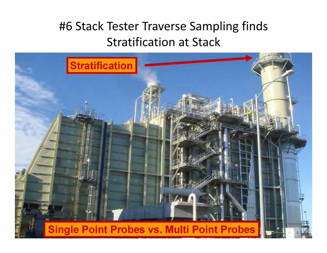
#6 Stack Tester Traverse Sampling findsStratification at Stack

#5 CO Catalyst Issues

#4 Aging Plant ‐‐Stack Characteristics Change

#3 Proactive Plant Policy‐Avoiding Excess Emissions Events

#2 It’s in Your Permit• TITLE V OPERATING PERMIT APCD2006‐TVP‐XXXXX • Issued To: • Solar Turbines Inc.
Site ID: APCD1976‐SITE‐xxxxx • Site Address • 100 Anywhere Road San Diego, CA 92123 • Mailing Address • P.O. Box 60609 San Diego CA 92186• Responsible Official: John Wayne, President; Paul Mc Cartney, Director
Packaging Systems • Facility Contact: Marilyn Monroe, Manager EHS Permit Information
Contact: Sharon Osbourne• Issued by the San Diego County Air Pollution Control District on This Title V
Operating Permit expires on . • Signed by:
John doe, P.E., Chief of Engineering

#1 You Fail Your RATA

Regulatory History
EMTIC GD‐031Allowed for Different sized holes that are only balanced at tested flow rate/ambient conditions (temperature) and would behave differently while in service in some cases. One of Reference Meters specified in test protocol Required Very High Pressure Drop and would interfere with as built conditions on standard CEM System Flow Rates SCAQMD Supplemental GuidelinesAllowed for alternate flow meters to allow test apparatus to not interfere with standard CEM System Flow Rates Required Array Sample Line to be assembled, hot and utilized.
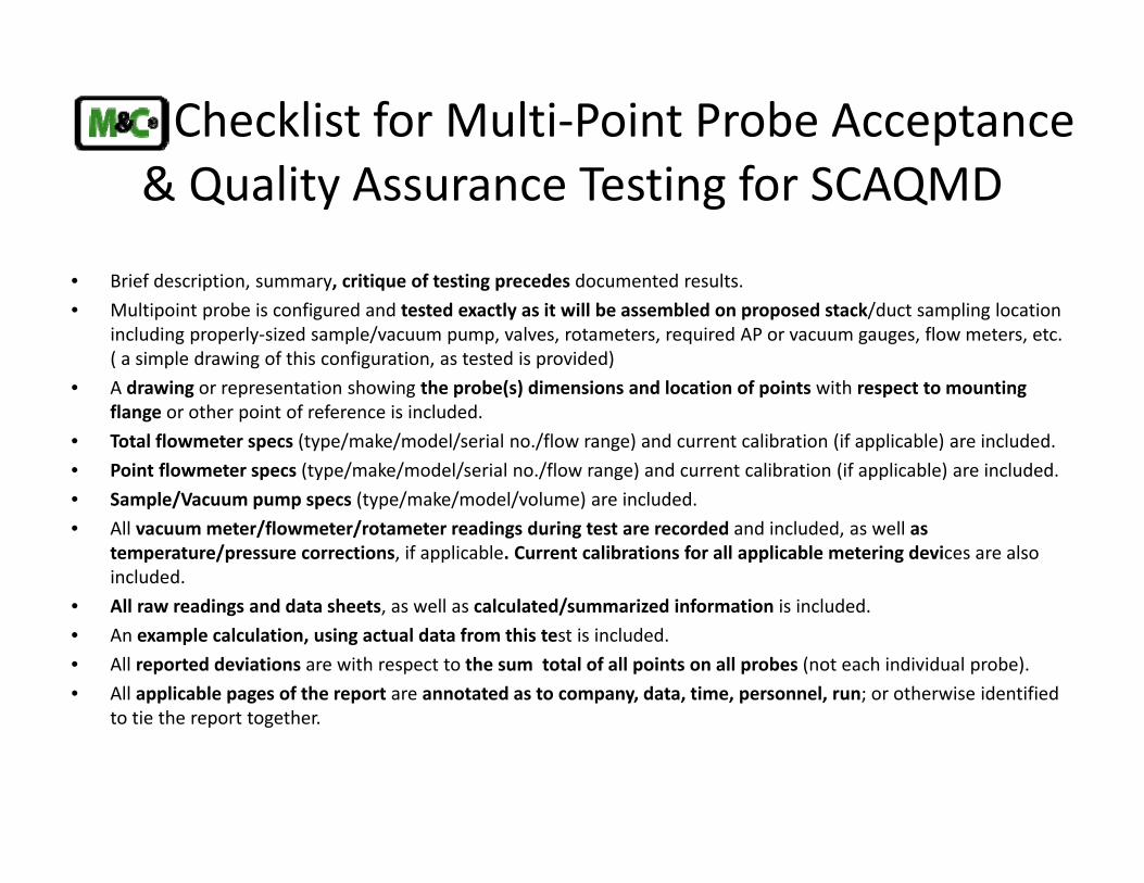
Checklist for Multi‐Point Probe Acceptance & Quality Assurance Testing for SCAQMD
• Brief description, summary, critique of testing precedes documented results.• Multipoint probe is configured and tested exactly as it will be assembled on proposed stack/duct sampling location
including properly‐sized sample/vacuum pump, valves, rotameters, required AP or vacuum gauges, flow meters, etc. ( a simple drawing of this configuration, as tested is provided)
• A drawing or representation showing the probe(s) dimensions and location of points with respect to mounting flange or other point of reference is included.
• Total flowmeter specs (type/make/model/serial no./flow range) and current calibration (if applicable) are included.• Point flowmeter specs (type/make/model/serial no./flow range) and current calibration (if applicable) are included.• Sample/Vacuum pump specs (type/make/model/volume) are included.• All vacuum meter/flowmeter/rotameter readings during test are recorded and included, as well as
temperature/pressure corrections, if applicable. Current calibrations for all applicable metering devices are also included.
• All raw readings and data sheets, as well as calculated/summarized information is included.• An example calculation, using actual data from this test is included.• All reported deviations are with respect to the sum total of all points on all probes (not each individual probe).• All applicable pages of the report are annotated as to company, data, time, personnel, run; or otherwise identified
to tie the report together.

Gas Laws‐How Emissions are Affected
Standard Temperature and Pressure (STP) and Ideal Gas LawsFluid flow rates and the volumes of liquids and gases are highly dependent on Temperature and Pressure.Standard Ambient Temperature (25C‐77F) and Pressure (1 atm) are utilized with gas analyzersGases are made up of molecules in constant random motionPressure—is a result of gases colliding and hitting walls of stack, which are perfectly elastic (no loss of kinetic energy)Temperature—proportional to the average kinetic energy of gases
Gas LawsIdeal Gas LawPV = nr T Boyle’s Law –assumes constant temperatureCharles Law‐assumes constant pressureGuy‐Lussac’s Law‐assumes constant volumeor“Real” Gas Law PV=ZnRTAllows for the compressibilty of gasAnalyzer companies allow for this compressibility factors whendeveloping the programs and factors to calculate results

Flow Related Forces from Gas Flow

Analyzer Bias’s from Pressure
Analyzers are sensitive to the pressure of the gas in the measurement cell.In calibration mode, a high gas flow rate from the calibration gas cylinder can pressurize the cell and lead to subsequent sample measurement biases. In spectroscopic absorption instruments, (NDIR) the gas concentration measured is related to the number of molecules in the light path. If the pressure is increased, the density of the sample gas is increased. The number of molecules in the light path increases correspondingly, even though their true concentration remains the same. Gas flow rate into the measurement cell must be the same in both calibration and sampling modes. Most gas manifolds are maintained to exhaust at a fixed pressure, the flow rates in both the calibration and sampling modes should be set so that this pressure is not exceeded. https://www.epa.gov/sites/production/files/2015‐05/documents/chapter_6_sources_of_bias_in_the_gas_analyzer.pdf

What Causes Stratification in a Stack

Probe Selection Criteria
• What are the characteristics of the stack‐height, size, interior, dimensions, sample locations, area classification?
• Any temporal variations (stratification) in the stack?
• Sample residence time?
From this information the type of probe‐traditional, dilution or multipoint can be selected. The correct engineered probe will be designed for your application.
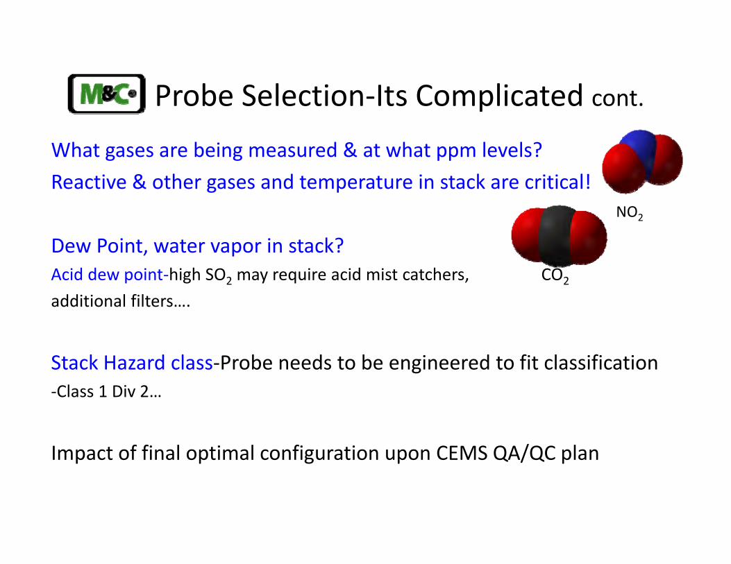
Probe Selection‐Its Complicated cont.What gases are being measured & at what ppm levels?Reactive & other gases and temperature in stack are critical!
Dew Point, water vapor in stack?Acid dew point‐high SO2 may require acid mist catchers, CO2
additional filters….
Stack Hazard class‐Probe needs to be engineered to fit classification‐Class 1 Div 2…
Impact of final optimal configuration upon CEMS QA/QC plan
NO2

Multipoint Design Criteria• Probe design is based on stack dimensions and conditions
• Stacks that are < 80 feet typically have flow disturbances in close proximity to sampling range (silencer can cause issues)
• Shorter stacks commonly have temporal variation
• Shorter stacks make the engineering of a multipoint probe more challenging due to shorter residence time, and shearing stress on the sample tubes
• M&C has engineered multipoint probes for stacks <80 feet

Probe Selection Criteria
• Is the sample gas “dirty”, with particulates, oil, or other contaminants ?
• How wet is the sample (dew point)?
• What temperature is the stack where gas will be sampled?
• What gases are being measured and at what ppm?
• What other gases/acids will be present, which may cause sampling & measurement issues or require additional components….. Filters?

Multi Point Probe Design‐Its Complicated
Stack coordinates, round or square, height (upstream/downstream distance from flow disturbances (method 1)
The stack temperature, flow, pressure and residence time are critical in designing the correct probe for your application.‐Mechanical Strength of probe required for high velocity and temperature.‐Prepare the correct flow rates and residence time and submit test procedure for approval from district
What fuel is used‐oil, coal, natural gas, waste, biofuels, Biomass, Digester Gas, trash, tires…‐The fuel contaminants & Particulates/dust loading will also effect the probe design in selecting the correct filters, shields, separators, acid mist catchers, blow back….

Using the Correct Probe is Critical
NOx measurement at sub 5 ppm is challengingSample Extraction is the Key to Good Measurement
The probe is the most critical component that can be controlled, in getting a representative sample.
Multipoint Probes ensure a representative sample due to theirdesign to sample across the stack at multiple points. More samplepoints mean a better sample of the gases to be measured evenwhen the sample conditioning vary.

Typical Multi‐Point Probe ConfigurationBasic & Required Components
Auxiliary Sample Port

Multipoint Probe 2 Point Stack
Cross Stack Example with 2 Probe Insertion Points
Each multipoint probe is custom engineered based on the individual stack characteristics.

Anatomy of a Multipoint Probe
• Probe Tubes or barrel
• Heated /unheated filters
• Probe controller
• Accumulator tank for blow back
• Mixing chamber
• Probe housing dependent on area classification
• Flange

Sample Tubes for Various Applications
Gas sampling requires an extension tube to properly extract sample from a specificpoint in the gas stream. The correct configuration of tubes and material is critical.
Examples:Screw‐in TubesFlange‐Welded TubesMultipoint TubesStainless HastelloySilcoat or SulfinertTeflonSintered Tubes
The sample tube material is based on the application. Temperature of sample,actual gas sampled, other gases present, width of stack, stratification, all playa critical role in tube or array design.

Cantilever Probe Tube

Sample Tube Material Choices
Options for Low dust loading <2 g/m3
SP2000/SS stainless steel up to 600oCSP2000/T teflon up to 160oCSP200/TI titanium up to 400oCSP2000/HC hastelloy up to 900oC

Factors to Consider for Filter Selection
Corrosive or Aggressive Sample ConstituentsHeated Or Unheated FilterWhat Gases Are To Be Monitored?Downstream Component Operating Temperature, Filter Heater Downstream Component Operating Pressure, Pressure Regulator and/or Relief Valve Required Sample Dewpoint (Acid, Hydrocarbon, or other), Separator and/or MembraneRequiredSpectral Interference In Sample, Adsorption MaterialArea ClassificationFlow Requirement
Probe tube prefilterHeated filter

Accumulator Tank
Accumulator Tank
Accumulator Tank in Uninsulatedprobe housing

Mixing Chamber

Probe Housing
Insulated Housing Uninsulated Housing

Flanges

Filters, Separators, Shields
Shield Heated Filter
ShieldSeparators

Multipoint Probe with Mixing Manifold

Multi Point Probes/Arrays/ManifoldsArrays are custom designed for stacks with gaseous stratification, or a variation in contaminant and/or diluent gas concentration with temporal variation (inconsistent stack flow). SCAQMD has been requesting multi point arrays for new applications.
The array consists of a number of sample extraction points or holes on one or more probes, configured to equally cover the proposed stack or duct cross sectional area of interest.The probe(s) are manifolded together to a high volume, positive displacement sample pump, must have flow and vacuum meters to monitor probe performance, as well as an audit Port.
Stream selection Manifold for SCR tuning in stratified flow
Arrays are common in applications <10 ppm NOx, in SCAQMD

Probe Placement in Stack is CriticalMethod 1— Sample and Velocity Traverses for Stationary Sources
Method 1 will provide guidance for the selection of sampling ports and traverse points at which sampling for air pollutants will be performed. Two procedures are provided a simplified and alternate. Acceptable for gas streams flowing in ducts, stacks or flues.
Not Applicable for conditions where:‐the flow is cyclonic or swirling ‐a stack is smaller than 12 in. in diameter, or 113 in.2 in cross‐sectional area

Probe Placement in Stack is Critical
Simplified ProcedureSampling or flow velocity site located at least eight stack or duct diameters downstream and two diameters upstream from any flow disturbance (bends, expansion or contractions in the stack or visible flame)
‐12 traverse points required circular/rectangular >24 inch stacks
‐8 traverse points required circular 12 to 24 inch stacks‐9 traverse points required rectangular 12 to 24 inch
stacks

EPA Method 1 Calculation

Performance Testing Criteria
With flow being critical to the operation of a multi‐point probe, the total flow rate of which the probe is certified or will be the minimum allowable volumetric flow rate for the CEMS to operate.
Performance Criteria for Acceptable Operation is Dictated by Statistical Criteria Specified in EMTIC GD‐031
Array Differential Pressure is also recorded during test procedure and the as tested differential pressure can be monitored on a periodic basis to insure that the multi‐point probe is operating in a balanced flow condition during field operations.

Performance TestingBench Testing is required in accordance with EPA/EMTIC Guidance Document (GD)‐031 Evaluation Procedures for Multi‐Hole Sample Probes
Assures that high‐volume sample pumps can provide constant & equal flow to all points of the probe arrayTest Measures Total & Individual Point Flow with:‐each individual sample point being within 10% of the overall flow average‐the sum of all individual point flows must be within 10% of the overall flow
Formal notification of CEMS initial approval or Probe recertification must be received by AQMD before the multi‐point probe is installed.

Probes: Correct Design is Necessary
Probe Filter is not correct for application‐too much particulate
Probe has cold spots, poor temperature controller –results in moisture in sampled gas and loss of sample gas in moisture
Probe Mounted Incorrectly or installed in wrong place in stack‐does not meet method 1 requirements, non representative sample
Blowback not setup correct‐need properly sized tank
Stratification in stack causes poor sampling‐need multipoint probe
Array setup incorrectly‐various configurations custom engineered

Quality AssuranceThe following must be addressed in the QA document for the Multi‐point probe1. Periodic system Blowback2. Visual inspection for corrosion, plugging, leaking3. Periodic Pump/Conditioning system PM (by vendor, or visual problems see 2)4. Total flow & vacuum readings must be periodically recorded5. Periodic AQMD audit of probe performance (by AQMD or 3rd party)
Multi‐point probes with reference method audit ports can not be used as a QARM CEMS/ Audit tube can not be used to validate performance of the probe to acquire a representative gas sample, since any errors (leaks, point bias) would be Mirrored by both CEMS

Good Maintenance Practices
• Check probe prefilter, if plugged replace
• Check probe temperature
• Check flow through to the sample
• Confirm CEMS operation by daily calibration
• Check Calibration and zero gas cylinders, pressure >200lbs.

The M&C Difference• M&C Tech Group has worked with SCAQMD when Multi Point Probes were
originally designed to meet the correct sampling guidelines.
• Design for each Multpoint Probe is custom to users application.
• M&C communicates and supports customers every step of the process from design to RATA .
• Over 15 years experience with every Multi Point Probe units, with all passing their RATA.
• Multi Point Probe support continues after certification.

Bernadette ShahinM&C Technology Group North America
805‐256‐5818bshahin@mac‐products.com
Thanks for ListeningQuestions ?
M&C Technology Group—Embracing Challenge