Embed Size (px)
Citation preview
MultiplexersXOR gates

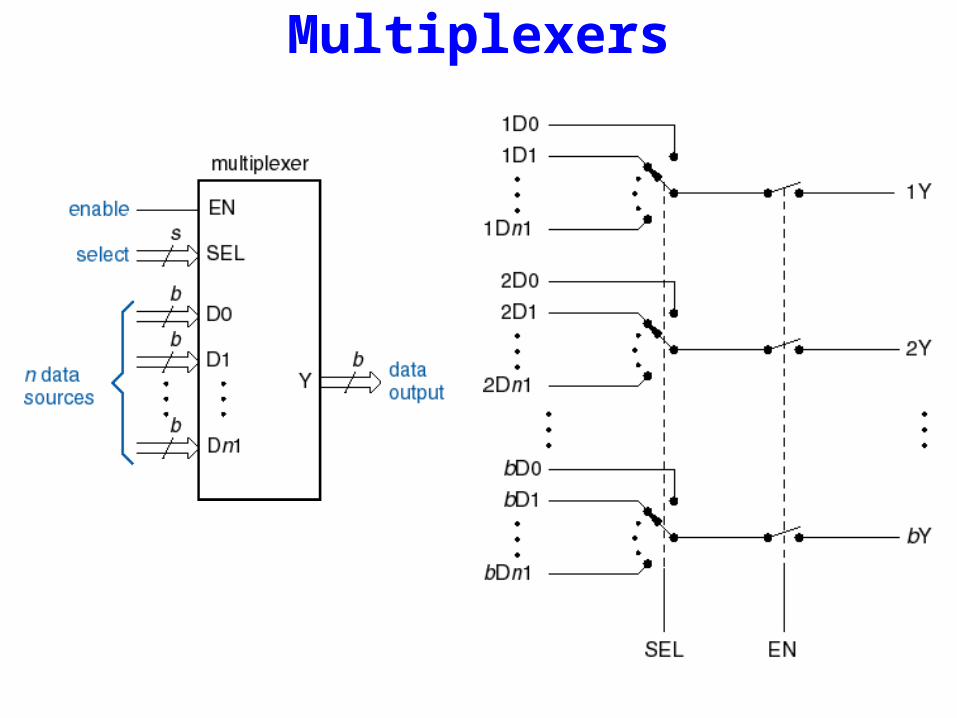
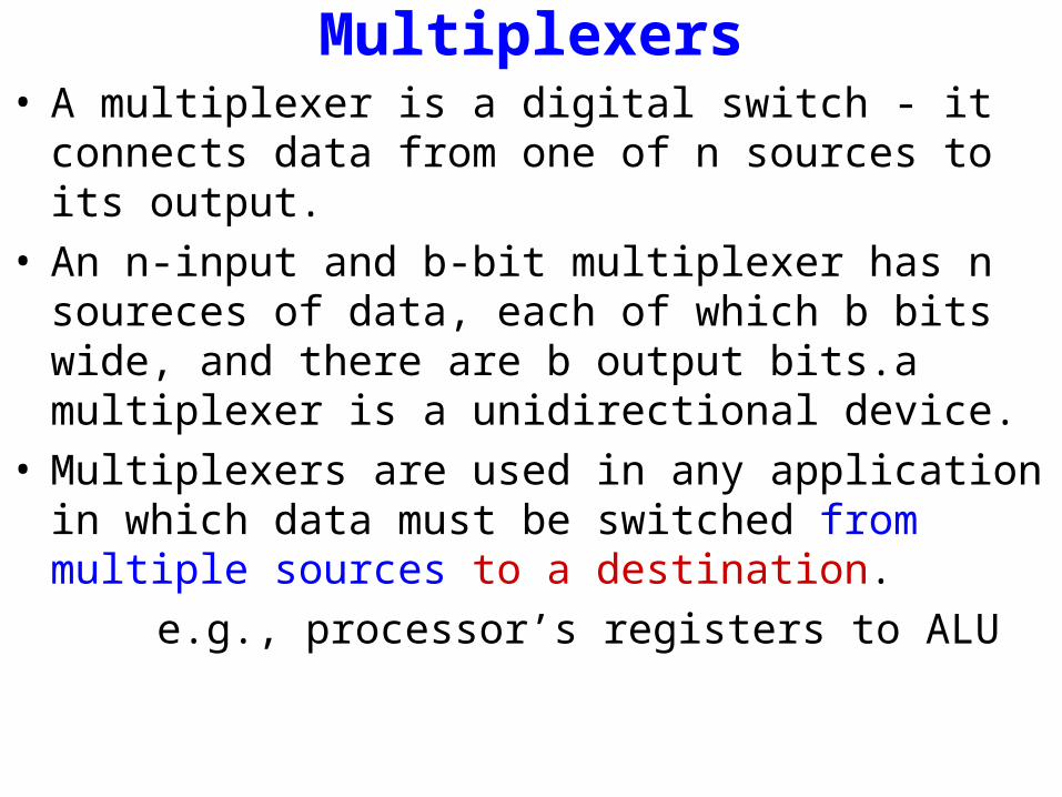
Multiplexers• A multiplexer is a digital switch - it connects data from one
of n sources to its output.• An n-input and b-bit multiplexer has n soureces of data,
each of which b bits wide, and there are b output bits.a multiplexer is a unidirectional device.
• Multiplexers are used in any application in which data must be switched from multiple sources to a destination.
e.g., processor’s registers to ALU
Multiplexers
Multiplexers• A multiplexer is a digital switch - it connects data from one
of n sources to its output.• An n-input and b-bit multiplexer has n soureces of data,
each of which b bits wide, and there are b output bits.a multiplexer is a unidirectional device.
• Multiplexers are used in any application in which data must be switched from multiple sources to a destination.
e.g., processor’s registers to ALU
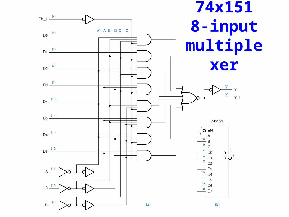
74x1518-input
multiplexer
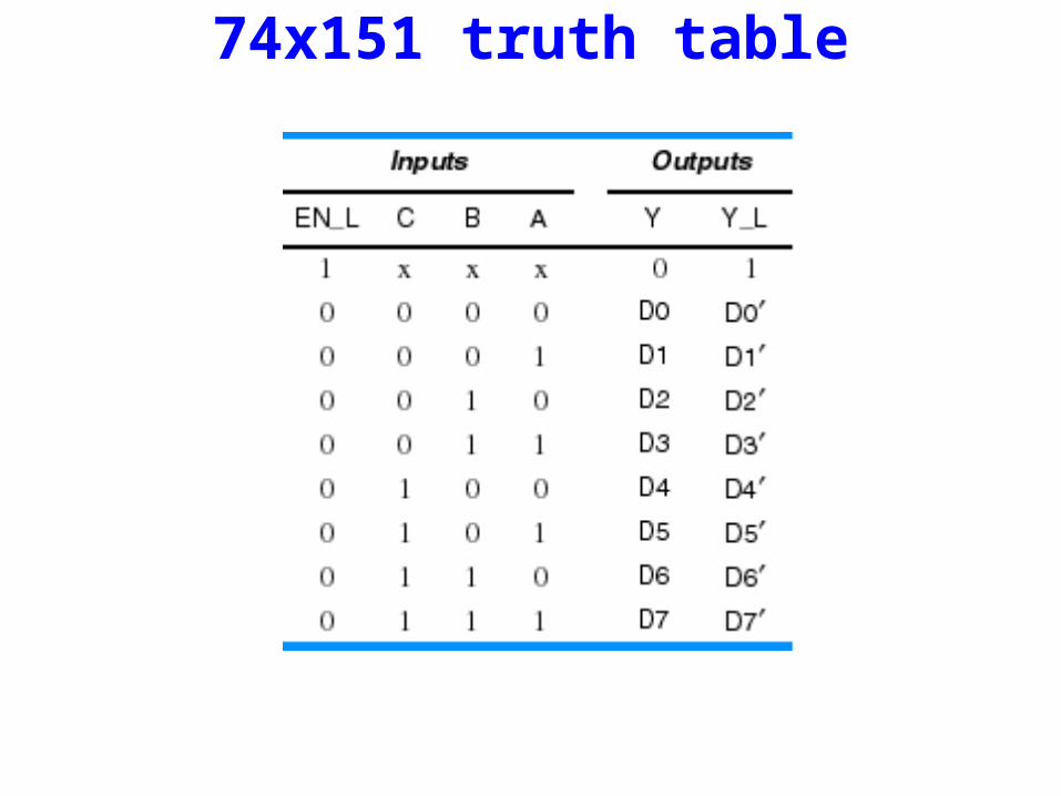
74x151 truth table
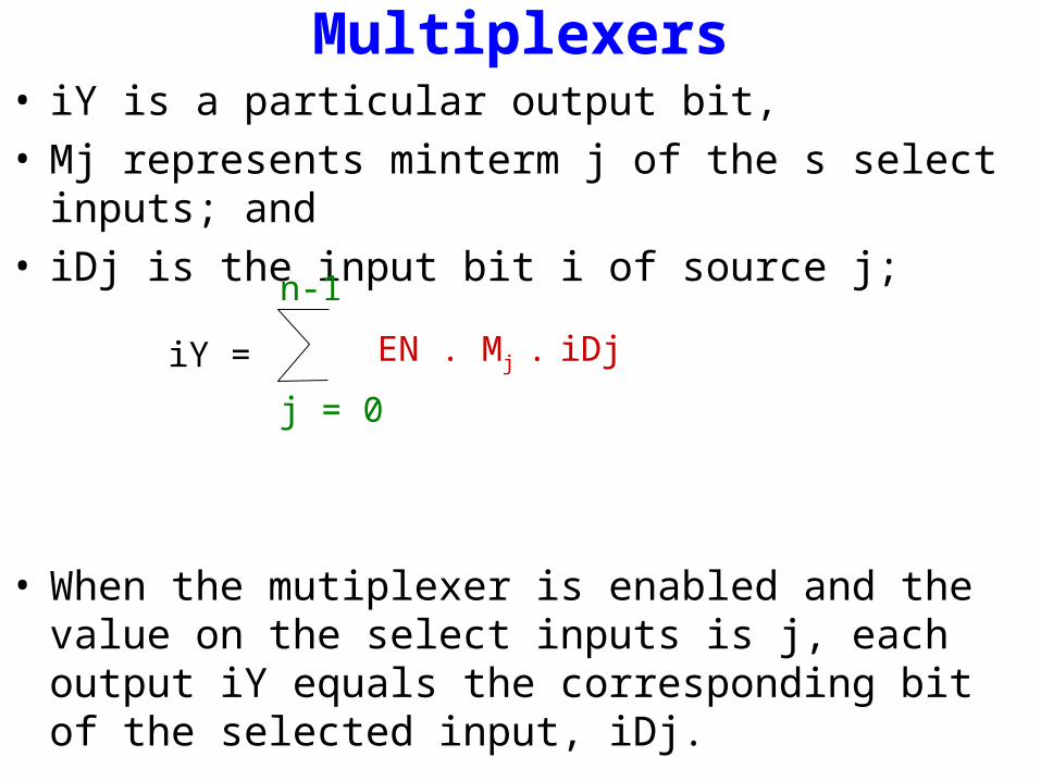
Multiplexers• iY is a particular output bit, • Mj represents minterm j of the s select inputs; and • iDj is the input bit i of source j;
• When the mutiplexer is enabled and the value on the select inputs is j, each output iY equals the corresponding bit of the selected input, iDj.
n-1
j = 0
EN . Mj . iDjiY =
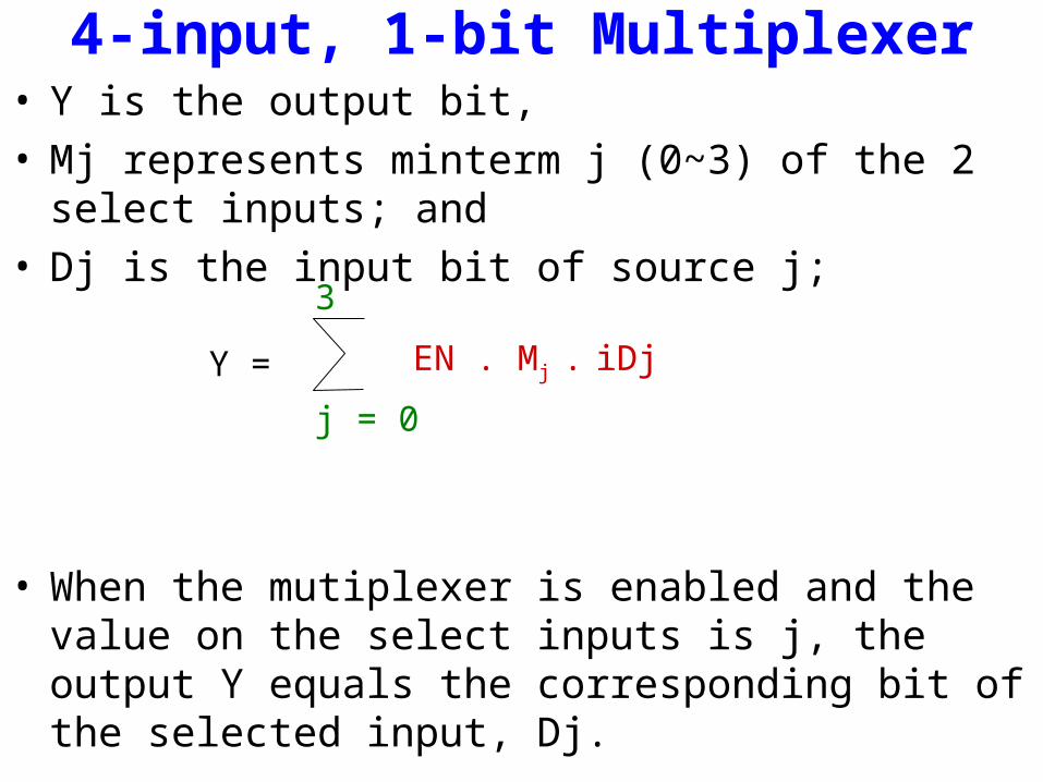
4-input, 1-bit Multiplexer• Y is the output bit, • Mj represents minterm j (0~3) of the 2 select inputs; and • Dj is the input bit of source j;
• When the mutiplexer is enabled and the value on the select inputs is j, the output Y equals the corresponding bit of the selected input, Dj.
3
j = 0
EN . Mj . iDjY =
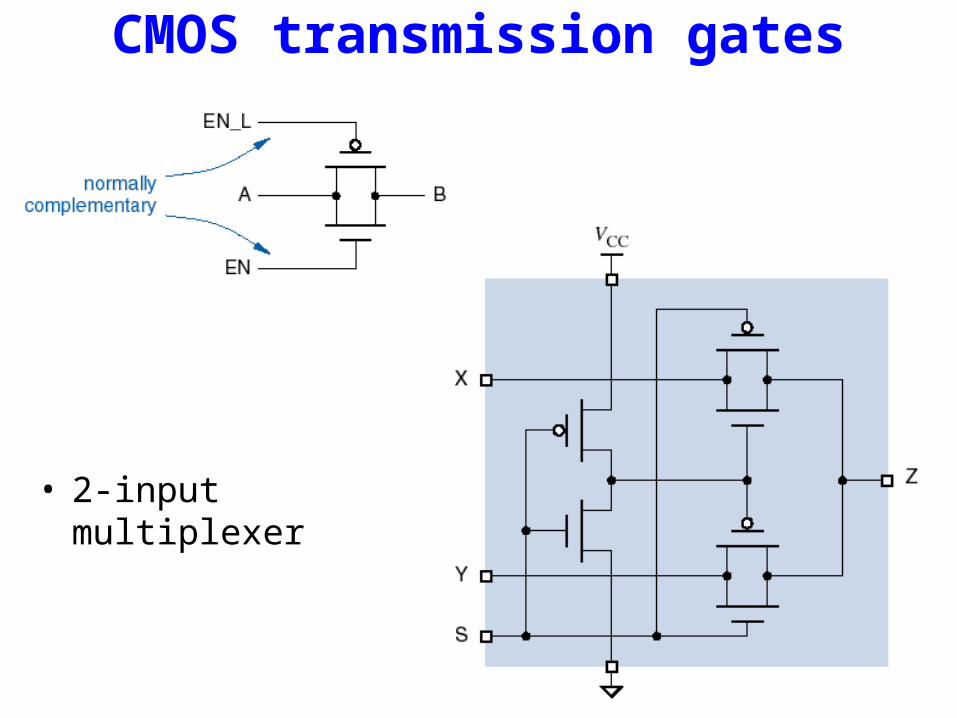
CMOS transmission gates
• 2-input multiplexer
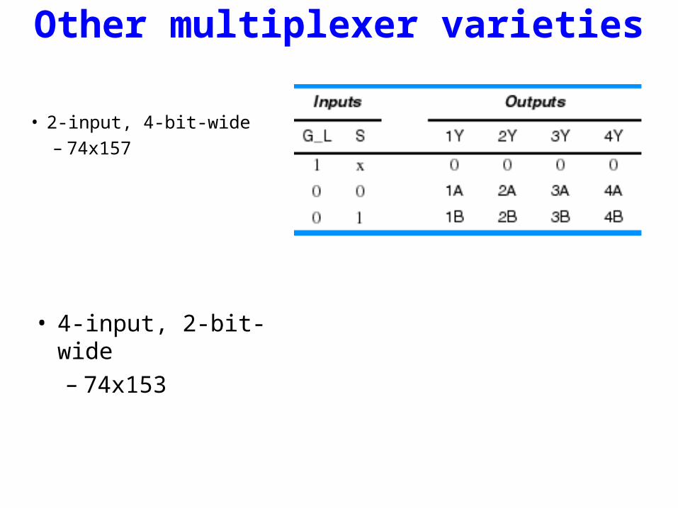
Other multiplexer varieties
• 2-input, 4-bit-wide– 74x157
• 4-input, 2-bit-wide– 74x153
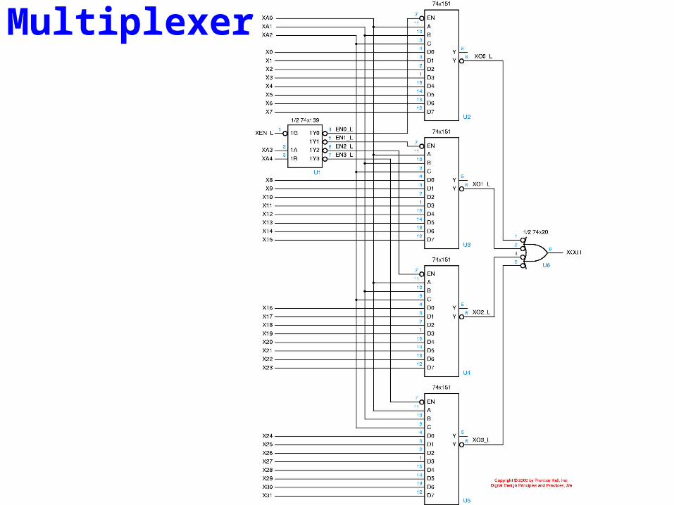
Multiplexers

ABEL code for 74x153-like mux
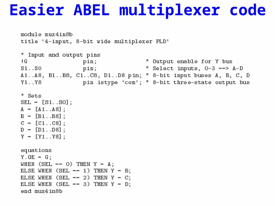
Easier ABEL multiplexer code

Barrel shifter design example• n data inputs, n data outputs• Control inputs specify number of positions to rotate or shift
data inputs• Example: n = 16
– DIN[15:0], DOUT[15:0], S[3:0] (shift amount)• Many possible solutions, all based on multiplexers
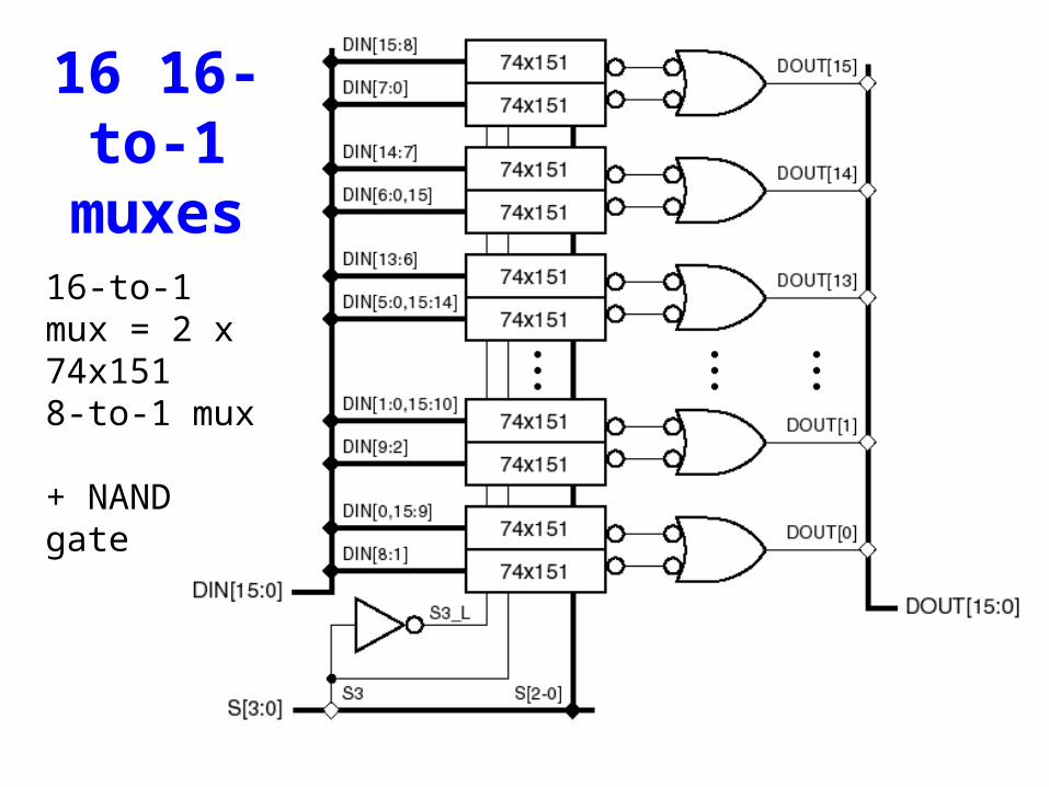
16 16-to-1 muxes
16-to-1 mux = 2 x 74x151 8-to-1 mux + NAND gate
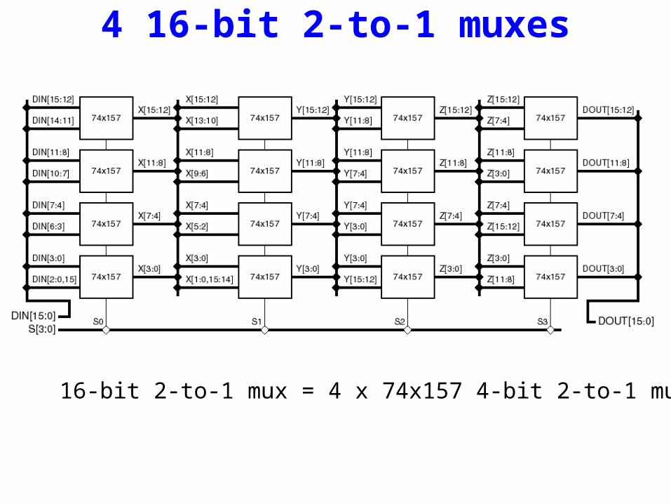
4 16-bit 2-to-1 muxes
16-bit 2-to-1 mux = 4 x 74x157 4-bit 2-to-1 mux
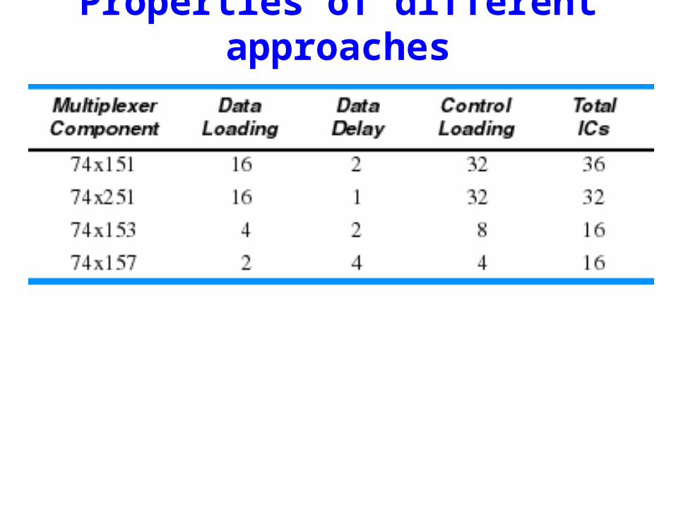
Properties of different approaches
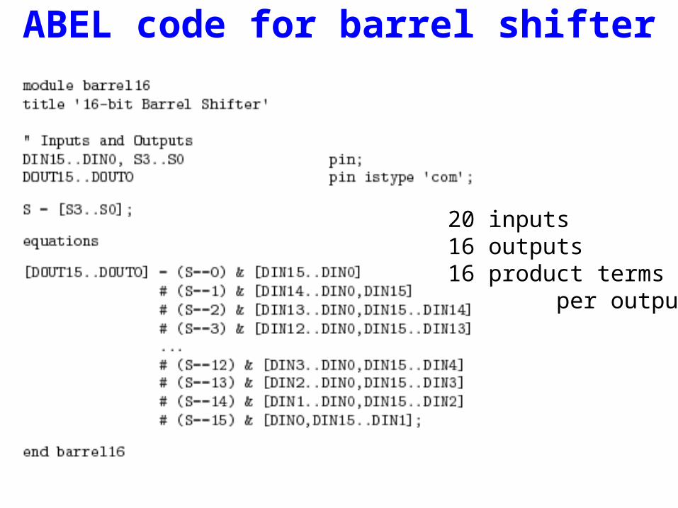
ABEL code for barrel shifter
20 inputs16 outputs16 product terms per output
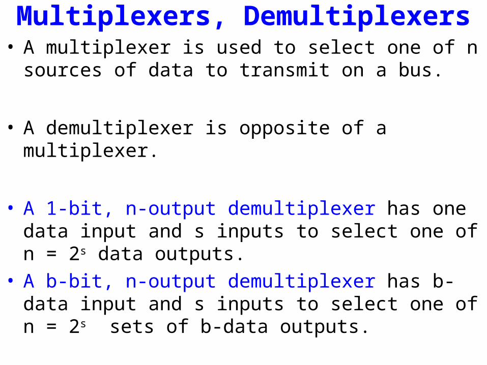
Multiplexers, Demultiplexers• A multiplexer is used to select one of n sources of data to
transmit on a bus.
• A demultiplexer is opposite of a multiplexer.
• A 1-bit, n-output demultiplexer has one data input and s inputs to select one of n = 2s data outputs.
• A b-bit, n-output demultiplexer has b-data input and s inputs to select one of n = 2s sets of b-data outputs.
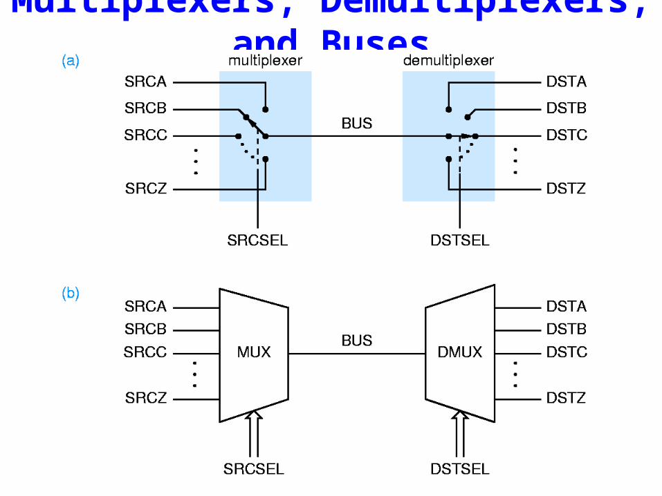
Multiplexers, Demultiplexers, and Buses

Multiplexers, Demultiplexers, and Buses• A multiplexer can be used to select one of n sources of data
to transmit on a bus.• A demultiplexer can be used to route the bus data to one of
m destinations.
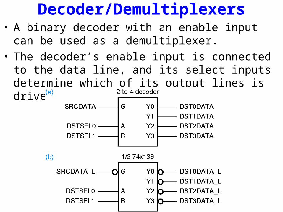
Decoder/Demultiplexers• A binary decoder with an enable input can be used as a
demultiplexer.• The decoder’s enable input is connected to the data line, and
its select inputs determine which of its output lines is driven with the data bit.
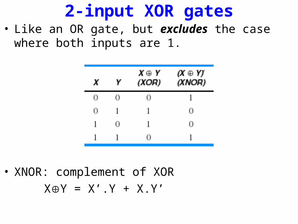
2-input XOR gates• Like an OR gate, but excludes the case where both inputs
are 1.
• XNOR: complement of XOR
XY = X’.Y + X.Y’

2-input XOR gatesXY = X’.Y + X.Y’
Commercial chip• 74x86• has four XOR gates
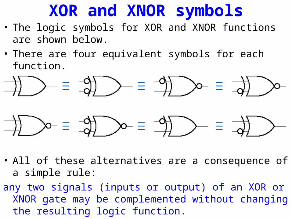
XOR and XNOR symbols• The logic symbols for XOR and XNOR functions are shown
below. • There are four equivalent symbols for each function.
• All of these alternatives are a consequence of a simple rule:
any two signals (inputs or output) of an XOR or XNOR gate may be complemented without changing the resulting logic function.
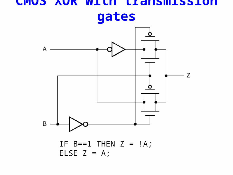
CMOS XOR with transmission gates
IF B==1 THEN Z = !A;ELSE Z = A;
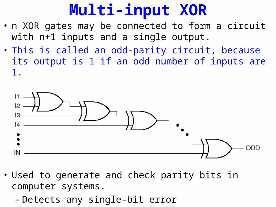
Multi-input XOR• n XOR gates may be connected to form a circuit with n+1
inputs and a single output.• This is called an odd-parity circuit, because its output is 1 if
an odd number of inputs are 1.
• Used to generate and check parity bits in computer systems.– Detects any single-bit error
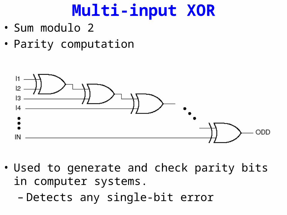
Multi-input XOR• Sum modulo 2• Parity computation
• Used to generate and check parity bits in computer systems.– Detects any single-bit error
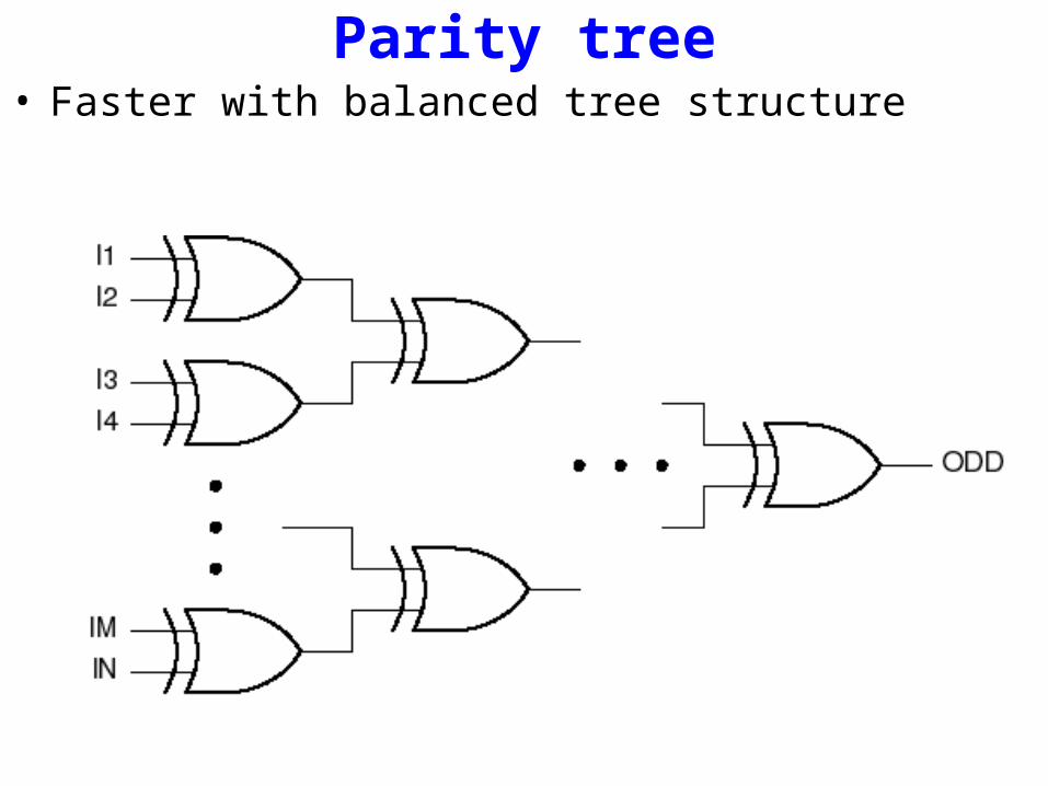
Parity tree• Faster with balanced tree structure
Next time• Comparators• Adders• Multipliers• Read-only memories (ROMs)