Embed Size (px)
Citation preview
MULTIPACTOR SIMULATIONS IN 325 MHz SUPERCONDUCTING
SPOKE CAVITY FOR AN ELECTRON ACCELERATOR∗
T. Kubo†, T. Saeki, KEK, High Energy Accelerator Research Organization, Tsukuba, Ibaraki, Japan
E. Cenni, Y. Iwashita, H. Tongu, Kyoto University, Uji, Kyoto, Japan
R. Hajima, M. Sawamura, Japan Atomic Energy Agency, JAEA, Tokai, Ibaraki, Japan
Abstract
To realize a compact industrial-use X-ray source with
the laser-Compton scattering, a 325MHz superconducting
spoke cavity for an electron accelerator operated at 4K is
under development. Design-optimizations of the first pro-
totype cavity were finished. Multipactor simulations were
carried out as parts of optimization efforts. In this paper,
procedures of multipactor simulations by using CST studio
suite are briefly introduced. Then results of simulations and
analyses to extract an optimum geometry are presented. A
relation between a cavity geometry and an intensity of mul-
tipactor is also commented.
INTRODUCTION
In order to realize an industrial-use laser-Compton scat-
tering compact X-ray source [1, 2], a superconducting cavity
for electron acceleration is currently under develop-
ment [3, 4]. We adopted a 325 MHz superconducting spoke
cavity. The spoke cavity [5] has a small diameter around
half the wavelength, namely, half a diameter of the elliptic
cavity, and make it possible to reduce RF frequency, fRF,
with keeping its compactness. By setting fRF = 325 MHz,
Bardeen-Cooper-Schrieffer (BCS) resistance (∝ f 2RF
) is sig-
nificantly reduced, and a cavity dissipation at 4 K nearly
equals to that of 1.3 GHz elliptic cavity at 2 K.
The genetic algorithm (GA) known as a method of multi-
objective optimization was used to design a spoke cavity by
Sawamura et al [3, 4]. Cavities with minimized Epk/Eacc
and Bpk/Eacc were generated, from which geometries that
maximize the achievable Eacc were extracted, where Eacc,
Epk and Bpk are the accelerating field, the peak electric-
field and the peak magnetic-field, respectively. There are
still degrees of freedom in the detailed design: corner radii
of the end-plate and the spoke-base, and so on. Fig. 1 shows
examples of geometries optimized by GA, which have sim-
ilar RF characteristics, but each has different corner radius
of the end-plate.
In order to finalize the detailed design, we carried out
MP simulations of cavities optimized by GA and extract a
model that may suppress a risk of MP as small as possible
[6, 7]. In this paper, procedures and results of MP sim-
ulations are briefly summarized. Relations between cavity
geometries and averaged secondary electron emission yield
are also commented.
∗ The work is supported by Photon and Quantum Basic Research
Coordinated Development Program from the Ministry of Education,
Culture, Sports, Science and Technology, Japan.† [email protected]
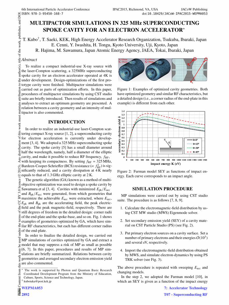
Figure 1: Examples of optimized cavity geometries. Both
have optimized geometry and similar RF characteristics, but
a detailed design (i.e., a corner radius of the end-plate in this
example) is different from each other.
Figure 2: Furman model SEY as functions of impact en-
ergy. Each curve corresponds to an impact angle.
SIMULATION PROCEDURE
MP simulations were carried out by using CST studio
suite. The procedure is as follows [7, 8, 9].
1. Calculate the electromagnetic-field distribution by us-
ing CST MW studio (MWS) Eigenmode solver.
2. Set secondary emission yield (SEY) of a cavity mate-
rial on CST Particle Studio (PS) (see Fig. 2).
3. Put primary electron sources on a cavity surface. Set a
number of primary electrons and their energiesO(103)
and several eV, respectively.
4. Import the electromagnetic-field distribution obtained
by MWS, and simulate electron-dynamics by using PS
TRK solver (see Fig. 3).
The above procedure is repeated with sweeping Eacc and
changing models.
In the step 2, we adopted the Furman model [10], in
which an SEY is given as a function of the impact energy
6th International Particle Accelerator Conference IPAC2015, Richmond, VA, USA JACoW PublishingISBN: 978-3-95450-168-7 doi:10.18429/JACoW-IPAC2015-WEPMA053
WEPMA0532892
Cont
entf
rom
this
wor
km
aybe
used
unde
rthe
term
soft
heCC
BY3.
0lic
ence
(©20
15).
Any
distr
ibut
ion
ofth
isw
ork
mus
tmai
ntai
nat
tribu
tion
toth
eau
thor
(s),
title
ofth
ew
ork,
publ
isher
,and
DO
I.
7: Accelerator TechnologyT07 - Superconducting RF
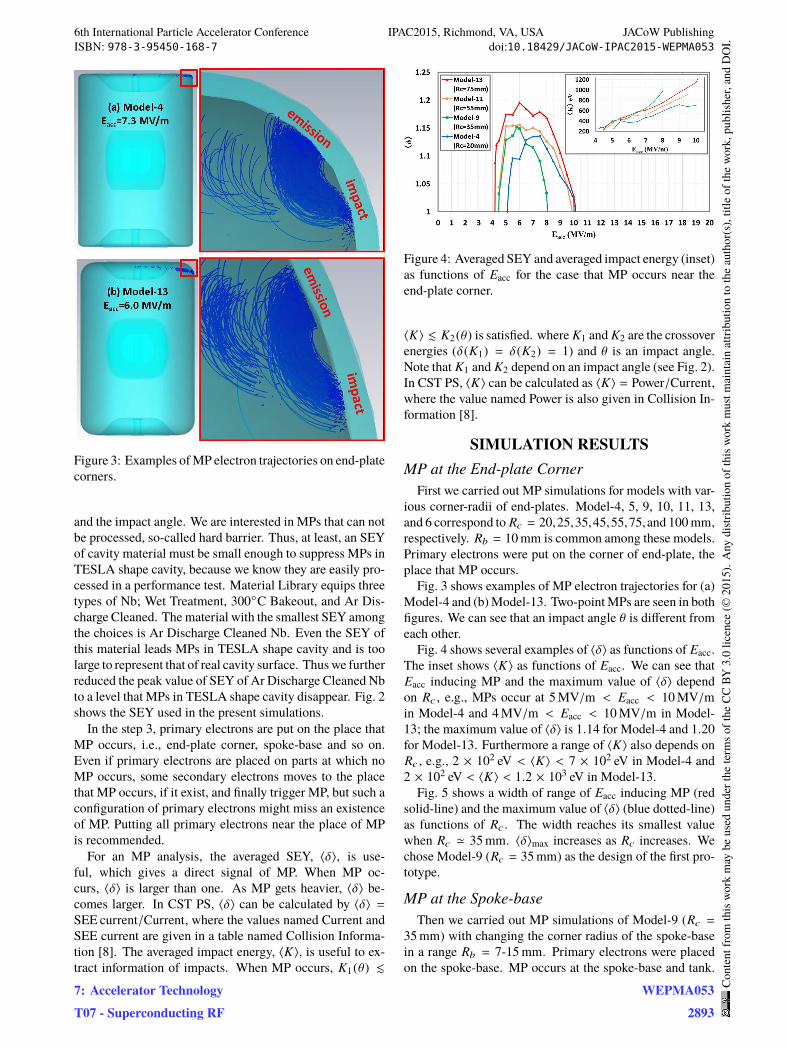
Figure 3: Examples of MP electron trajectories on end-plate
corners.
and the impact angle. We are interested in MPs that can not
be processed, so-called hard barrier. Thus, at least, an SEY
of cavity material must be small enough to suppress MPs in
TESLA shape cavity, because we know they are easily pro-
cessed in a performance test. Material Library equips three
types of Nb; Wet Treatment, 300◦C Bakeout, and Ar Dis-
charge Cleaned. The material with the smallest SEY among
the choices is Ar Discharge Cleaned Nb. Even the SEY of
this material leads MPs in TESLA shape cavity and is too
large to represent that of real cavity surface. Thus we further
reduced the peak value of SEY of Ar Discharge Cleaned Nb
to a level that MPs in TESLA shape cavity disappear. Fig. 2
shows the SEY used in the present simulations.
In the step 3, primary electrons are put on the place that
MP occurs, i.e., end-plate corner, spoke-base and so on.
Even if primary electrons are placed on parts at which no
MP occurs, some secondary electrons moves to the place
that MP occurs, if it exist, and finally trigger MP, but such a
configuration of primary electrons might miss an existence
of MP. Putting all primary electrons near the place of MP
is recommended.
For an MP analysis, the averaged SEY, ⟨δ⟩, is use-
ful, which gives a direct signal of MP. When MP oc-
curs, ⟨δ⟩ is larger than one. As MP gets heavier, ⟨δ⟩ be-
comes larger. In CST PS, ⟨δ⟩ can be calculated by ⟨δ⟩ =
SEE current/Current, where the values named Current and
SEE current are given in a table named Collision Informa-
tion [8]. The averaged impact energy, ⟨K⟩, is useful to ex-
tract information of impacts. When MP occurs, K1(θ) ≲
Figure 4: Averaged SEY and averaged impact energy (inset)
as functions of Eacc for the case that MP occurs near the
end-plate corner.
⟨K⟩ ≲ K2(θ) is satisfied. where K1 and K2 are the crossover
energies (δ(K1) = δ(K2) = 1) and θ is an impact angle.
Note that K1 and K2 depend on an impact angle (see Fig. 2).
In CST PS, ⟨K⟩ can be calculated as ⟨K⟩ = Power/Current,
where the value named Power is also given in Collision In-
formation [8].
SIMULATION RESULTS
MP at the E
First we carried out MP simulations for models with var-
ious corner-radii of end-plates. Model-4, 5, 9, 10, 11, 13,
and 6 correspond to Rc = 20,25,35,45,55,75,and 100 mm,
respectively. Rb = 10 mm is common among these models.
Primary electrons were put on the corner of end-plate, the
place that MP occurs.
Fig. 3 shows examples of MP electron trajectories for (a)
Model-4 and (b) Model-13. Two-point MPs are seen in both
figures. We can see that an impact angle θ is different from
each other.
Fig. 4 shows several examples of ⟨δ⟩ as functions of Eacc.
The inset shows ⟨K⟩ as functions of Eacc. We can see that
Eacc inducing MP and the maximum value of ⟨δ⟩ depend
on Rc , e.g., MPs occur at 5 MV/m < Eacc < 10 MV/m
in Model-4 and 4 MV/m < Eacc < 10 MV/m in Model-
13; the maximum value of ⟨δ⟩ is 1.14 for Model-4 and 1.20
for Model-13. Furthermore a range of ⟨K⟩ also depends on
Rc , e.g., 2 × 10² eV < ⟨K⟩ < 7 × 10² eV in Model-4 and
2 × 10² eV < ⟨K⟩ < 1.2 × 10³ eV in Model-13.
Fig. 5 shows a width of range of Eacc inducing MP (red
solid-line) and the maximum value of ⟨δ⟩ (blue dotted-line)
as functions of Rc . The width reaches its smallest value
when Rc ≃ 35 mm. ⟨δ⟩max increases as Rc increases. We
chose Model-9 (Rc = 35 mm) as the design of the first pro-
totype.
MP at the Spoke-base
Then we carried out MP simulations of Model-9 (Rc =
35 mm) with changing the corner radius of the spoke-base
in a range Rb = 7-15 mm. Primary electrons were placed
on the spoke-base. MP occurs at the spoke-base and tank.
EEnd-plate Corner
6th International Particle Accelerator Conference IPAC2015, Richmond, VA, USA JACoW PublishingISBN: 978-3-95450-168-7 doi:10.18429/JACoW-IPAC2015-WEPMA053
7: Accelerator TechnologyT07 - Superconducting RF
WEPMA0532893
Cont
entf
rom
this
wor
km
aybe
used
unde
rthe
term
soft
heCC
BY3.
0lic
ence
(©20
15).
Any
distr
ibut
ion
ofth
isw
ork
mus
tmai
ntai
nat
tribu
tion
toth
eau
thor
(s),
title
ofth
ew
ork,
publ
isher
,and
DO
I.
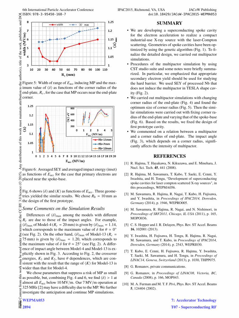
Figure 5: Width of range of Eacc inducing MP and the max-
imum value of ⟨δ⟩ as functions of the corner radius of the
end-plate, Rc , for the case that MP occurs near the end-plate
corner.
Figure 6: Averaged SEY and averaged impact energy (inset)
as functions of Eacc for the case that primary electrons are
placed near the spoke-base.
Fig. 6 shows ⟨δ⟩ and ⟨K⟩ as functions of Eacc. Three geome-
tries yielded the similar results. We chose Rb = 10 mm as
the design of the first prototype.
Some Comments on the Simulation Results
Differences of ⟨δ⟩max among the models with different
Rc are due to those of the impact angles. For example,
⟨δ⟩max of Model-4 (Rc = 20 mm) is given by ⟨δ⟩max = 1.14,
which corresponds to the maximum value of δ for θ ≃ 0◦
(see Fig. 2). On the other hand, ⟨δ⟩max of Model-13 (Rc =
75 mm) is given by ⟨δ⟩max = 1.20, which corresponds to
the maximum value of δ for θ ≃ 25◦ (see Fig. 2). A differ-
ence of impact angle between Model-4 and Model-13 is ex-
plicitly shown in Fig. 3. According to Fig. 2, the crossover
energies, K1 and K2, have θ dependences, which are con-
sistent with the result that the range of ⟨K⟩ for Model-13 is
wider than that for Model-4.
We chose parameters that suppress a risk of MP as small
as possible, but, combining Fig. 4 and 6, we find ⟨δ⟩ > 1 at
almost all Eacc below 10 MV/m. Our 7 MV/m operation at
325 MHz [2] may have a difficulty due to the MP. We further
investigate the anticipation and continue MP simulations.
SUMMARY
• We are developing a superconducting spoke cavity
for the electron acceleration to realize a compact
industrial-use X-ray source with the laser-Compton
scattering. Geometries of spoke cavities have been op-
timized by using the genetic algorithm (Fig. 1). To fi-
nalize the detailed design, we carried out multipactor
simulations.
• Procedures of the multipactor simulation by using
CST studio suite and some notes were briefly summa-
rized. In particular, we emphasized that appropriate
secondary electron yield should be used for studying
the hard barrier. We used SEY of processed Nb that
does not induce the multipactor in TESLA shape cav-
ity (Fig. 2).
• We carried out multipactor simulations with changing
corner radius of the end-plate (Fig. 4) and found the
optimum size of corner radius (Fig. 5). Then the simi-
lar simulations were carried out with fixing corner ra-
dius of the end-plate and varying that of the spoke-base
(Fig. 6). Based on the results, we fixed the design of
first prototype cavity.
• We commented on a relation between a multipactor
and a corner radius of end-plate. The impact angle
(Fig. 3), which depends on a corner radius, signifi-
cantly affects the intensity of multipactor.
REFERENCES
[1] R. Hajima, T. Hayakawa, N. Kikuzawa, and E. Minehara, J.
Nucl. Sci. Tech. 45, 441 (2008).
[2] R. Hajima, M. Sawamura, T. Kubo, T. Saeki, E. Cenni, Y.
Iwashita, and H. Tongu, “Development of superconducting
spoke cavities for laser compton scattered X-ray sources", in
this proceedings, WEPMA056.
[3] M. Sawamura, R. Hajima, R. Nagai, T. Kubo, H. Fujisawa,
and Y. Iwashita, in Proceedings of IPAC2014, Doresden,
Germany (2014), p. 1946, WEPRO005.
[4] M. Sawamura, R. Hajima, R. Nagai, and N. Nishimori, in
Proceedings of SRF2011, Chicago, IL USA (2011), p. 165,
MOPO036.
[5] C. S. Hopper and J. R. Delayen, Phys. Rev. ST Accel. Beams
16, 102001 (2013).
[6] Y. Iwashita, H. Fujisawa, H. Tongu, R. Hajima, R. Nagai,
M. Sawamura, and T. Kubo, in Proceedings of IPAC2014,
Doresden, Germany (2014), p. 2543, WEPRI030.
[7] T. Kubo, E. Cenni, H. Fujisawa, R. Hajima, Y. Iwashita,
T. Saeki, M. Sawamura, and H. Tongu, in Proceedings of
LINAC14, Geneva, Switzerland (2013), p. 1030, THPP075.
[8] G. Romanov, private communications.
[9] G. Romanov, in Proceedings of LINAC08, Victoria, BC,
Canada (2008), p. 166, MOP043.
[10] M. A. Furman and M. T. F. Pivi, Phys. Rev. ST Accel. Beams
5, 124404 (2002).
6th International Particle Accelerator Conference IPAC2015, Richmond, VA, USA JACoW PublishingISBN: 978-3-95450-168-7 doi:10.18429/JACoW-IPAC2015-WEPMA053
WEPMA0532894
Cont
entf
rom
this
wor
km
aybe
used
unde
rthe
term
soft
heCC
BY3.
0lic
ence
(©20
15).
Any
distr
ibut
ion
ofth
isw
ork
mus
tmai
ntai
nat
tribu
tion
toth
eau
thor
(s),
title
ofth
ew
ork,
publ
isher
,and
DO
I.
7: Accelerator TechnologyT07 - Superconducting RF