Embed Size (px)
Citation preview
JOURNAL OF LATEX CLASS FILES, VOL. 14, NO. 8, AUGUST 2015 1
Experimental Study of the Multipactor Effect in aPartially Dielectric-Loaded Rectangular Waveguide
Andres Berenguer, Angela Coves, Senior Member, IEEE Benito Gimeno, Member, IEEE,Enrique Bronchalo, and Vicente E. Boria, Fellow
Abstract—This letter presents the experimental study of themultipactor threshold in a partially dielectric-loaded rectangularwaveguide, whose results validate a multipactor model recentlydeveloped by the authors, which includes the charge distributionappearing on the dielectric surface during the multipactordischarge. First, the variation of the multipactor RF voltagethreshold has been theoretically analyzed in different waveguideconfigurations: in an empty waveguide, and also in the casesof a one-sided and two-sided dielectric-loaded waveguides. Toreach this aim, an in-house Monte-Carlo simulation tool has beendeveloped. The Secondary Electron Yield (SEY) of the metallicand dielectric materials used in the numerical simulations havebeen measured experimentally. Finally, an aluminum WR-75symmetric E-plane rectangular waveguide transformer has beendesigned and fabricated, in which several multipaction testshave been carried out to validate the in-house software tool,demonstrating an excellent agreement between the simulationresults and the experimental data.
Index Terms—Multipactor effect, RF breakdown, dielectric,rectangular waveguide, waveguide transformer, Secondary Elec-tron Yield (SEY).
I. INTRODUCTION
MULTIPACTOR is a well-known and undesired high-power effect affecting microwave components oper-
ating under high-vacuum conditions [1]. Such multipactor-affected components are present in a wide range of differentscenarios, such as passive components of satellite communica-tion payloads, klystrons, and particle accelerators. Multipactorconsists of a generation of an electron avalanche that mightresult in a resonant discharge with harmful consequences forthe involved device. Among these negative effects, it is worthmentioning the degradation of the component, detuning ofresonant cavities, power dissipation, and a significant increaseof noise in communications. Multipactor has been deeplyinvestigated in several types of microwave waveguides withsimple geometries, such as parallel-plate [1], rectangular [2]–[4], circular [5], elliptical [6], and coaxial waveguides [7],[8]. However, there are few contributions to the study of themultipactor effect in partially dielectric-loaded waveguides inthe scenario of RF systems for space applications [9]–[12],and most of them use the parallel-plate waveguide approach.In a recent work of the authors [13], the multipactor effect in
A. Berenguer, A. Coves and E. Bronchalo are with the Departmentof Communications Engineering, Universidad Miguel Hernandez de Elche,Elche, Spain (e-mail: [email protected]).
B. Gimeno is with the Department of Applied Physics andElectromagnetism-IFIC, Universidad de Valencia, Burjasot, Spain.
V. E. Boria is with the Departamento de Comunicaciones-ITEAM, Univer-sitat Politecnica de Valencia, Valencia, Spain.
a partially dielectric-loaded rectangular waveguide has beenanalyzed from a theoretical point of view for the first time,considering both the RF fields inside the waveguide and thecharge distribution appearing on the dielectric surface duringthe multipactor discharge. In order to validate the numericalmethod presented in [13] with experimental data, in this letterwe present the multipactor threshold results on an aluminumWR-75 symmetric E-plane rectangular waveguide transformer,partially filled with a thin dielectric layer, specially designedfor this experiment. The Secondary Emission Yield (SEY)properties of the different materials employed in this experi-ment have been measured and used in the numerical simula-tions. The variation of the multipactor RF voltage thresholdhas been theoretically analyzed for this waveguide with andwithout dielectric material, and its high power behaviour hasbeen measured, demonstrating an excellent agreement betweenthe simulated results and the experimental data.
II. SIMULATION MODEL AND SEY MEASUREMENTS
In this work, the multipactor effect in a non-standardaluminum rectangular waveguide of width a = 19.05mmand heigth b = 0.4mm, which is partially filled with athin dielectric layer and corresponds to the central waveguidesection of a symmetric E-plane waveguide transformer, hasbeen analyzed and measured. To study the multipactor effectin this waveguide, a multipactor simulation code based on theMonte-Carlo method has been developed [13], which is anextension of previous studies of multipactor on a partiallydielectric-loaded parallel-plate waveguide [9], [10]. In theemployed multipactor code, both the RF and DC fields insidethe waveguide have been rigorously considered, the last onebeing associated to the charge distribution appearing on thedielectric surface during the multipactor discharge. In order todetermine this DC field, the electrostatic potential due to a unitpoint charge inside the waveguide has been first calculated bymeans of very efficient numerical summation and integrationtechniques [13]. Then, using the superposition principle, theelectrostatic potential in the waveguide due to the set ofcharges on the dielectric surface can be obtained rigorously byadding the individual contribution of each charge, and finallythe Edc field is obtained by numerical differentiation. Thechosen dielectric film is DuPont Teflon R⃝ Fluorinated EthylenePropylene (FEP) Fluoroplastic Film Type C [14], which iscommonly used in space applications, with ϵr = 2.1 and avery small thickness h = 0.025mm. Therefore, the electricalperformance of the waveguide transformer will scarcely be
JOURNAL OF LATEX CLASS FILES, VOL. 14, NO. 8, AUGUST 2015 2
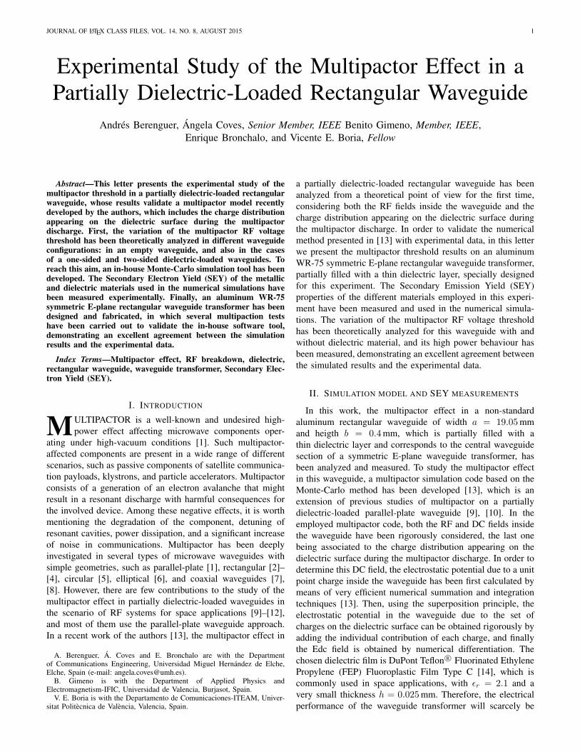
Fig. 1. SEY measured curves for the materials employed in this work.
modified when adding the dielectric film. It is well knownthat the SEY depends on material, primary electron kineticenergy, incident angle and surface state (surface composition,morphology of the structure, porosity and roughness) [15],[16]. The SEY properties of the metallic and dielectric mate-rials employed in this experiment have been measured at theVSC/ESA laboratory, Valencia (Spain) [17], and they havebeen used in the multipactor simulations shown in the nextsection. For these materials, SEY at normal incidence wasdetermined as a function of primary electron kinetic energyin the range 5-1000 eV, by measuring the sample current toground when bombarded by a calibrated continuous primaryelectron beam of about 5 nA in the case of aluminum. Inthe case of teflon, the measurement of the secondary electronemission was done by using an electron gun configured inpulsed mode for sending a single electron dose of less than106 e/cm2. After each dose, and before varying the primaryelectron energy, the sample was electrically neutralized.
Fig. 1 shows the measured SEY curves for aluminum andTeflon R⃝. It is worth mentioning that the maximum SEY of2.8 measured for teflon is quite similar to the maximum SEYmeasured for aluminum (2.6). On the other hand, aluminumshows a lower first cross-over energy for the SEY curve (W1 =15 eV) than the measured first cross-over value in teflon (W1 =36 eV). These features are going to condition the multipactorresults shown next.
III. NUMERICAL AND EXPERIMENTAL RESULTS
We have used the experimental SEY curves shown in Fig. 1to compute the RF multipactor threshold voltage Vth in thealuminum rectangular waveguide of width a = 19.05mm andheigth b = 0.4mm under study, considering three differentconfigurations: 1: without dielectric material; 2: covering thebottom surface of the waveguide with a thin film of teflon(which has thickness h = 0.025mm and ϵr = 2.1); 3: coveringthe top and bottom surfaces of the waveguide with teflon.Thus, the empty gap waveguide in the vertical dimensiond = b − h where the electrons can travel in each casewill take values of 0.4, 0.375 and 0.35 mm, respectively. Inorder to compute the multipactor RF Vth at a given f × dpoint, the same procedure used in [13] has been followed: for
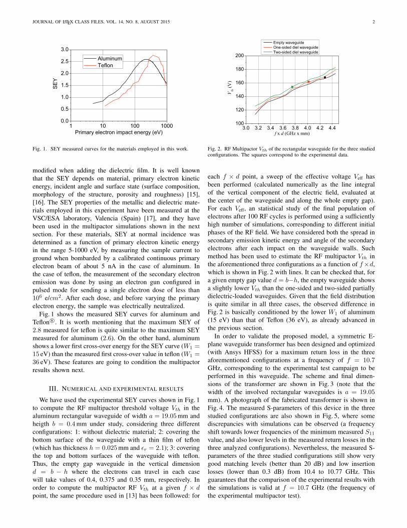
Fig. 2. RF Multipactor Vth of the rectangular waveguide for the three studiedconfigurations. The squares correspond to the experimental data.
each f × d point, a sweep of the effective voltage Veff hasbeen performed (calculated numerically as the line integralof the vertical component of the electric field, evaluated atthe center of the waveguide and along the whole empty gap).For each Veff, an statistical study of the final population ofelectrons after 100 RF cycles is performed using a sufficientlyhigh number of simulations, corresponding to different initialphases of the RF field. We have considered both the spread insecondary emission kinetic energy and angle of the secondaryelectrons after each impact on the waveguide walls. Suchmethod has been used to estimate the RF multipactor Vth inthe aforementioned three configurations as a function of f×d,which is shown in Fig. 2 with lines. It can be checked that, fora given empty gap value d = b−h, the empty waveguide showsa slightly lower Vth than the one-sided and two-sided partiallydielectric-loaded waveguides. Given that the field distributionis quite similar in all three cases, the observed difference inFig. 2 is basically conditioned by the lower W1 of aluminum(15 eV) than that of Teflon (36 eV), as already advanced inthe previous section.
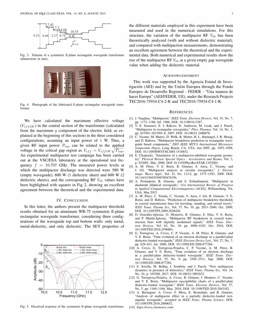
In order to validate the proposed model, a symmetric E-plane waveguide transformer has been designed and optimized(with Ansys HFSS) for a maximum return loss in the threeaforementioned configurations at a frequency of f = 10.7GHz, corresponding to the experimental test campaign to beperformed in this waveguide. The scheme and final dimen-sions of the transformer are shown in Fig. 3 (note that thewidth of the involved rectangular waveguides is a = 19.05mm). A photograph of the fabricated transformer is shown inFig. 4. The measured S-parameters of this device in the threestudied configurations are also shown in Fig. 5, where somediscrepancies with simulations can be observed (a frequencyshift towards lower frequencies of the minimum measured S11
value, and also lower levels in the measured return losses in thethree analyzed configurations). Nevertheless, the measured S-parameters of the three studied configurations still show verygood matching levels (better than 20 dB) and low insertionlosses (lower than 0.3 dB) from 10.4 to 10.77 GHz. Thisguarantees that the comparison of the experimental results withthe simulations is valid at f = 10.7 GHz (the frequency ofthe experimental multipactor test).
JOURNAL OF LATEX CLASS FILES, VOL. 14, NO. 8, AUGUST 2015 3
Fig. 3. Scheme of a symmetric E-plane rectangular waveguide transformer(dimensions in mm).
Fig. 4. Photograph of the fabricated E-plane rectangular waveguide trans-former.
We have calculated the maximum effective voltage(Veff1W ) in the central section of the transformer (calculatedfrom the maximum y component of the electric field, as ex-plained at the beginning of this section) in the three consideredconfigurations, assuming an input power of 1 W. Thus, agiven RF input power Pinp can be related to the appliedvoltage in the critical gap region as Veff = Veff1W
√Pinp.
An experimental multipactor test campaign has been carriedout at the VSC/ESA laboratory at the operational test fre-quency f = 10.707 GHz. The measured power levels atwhich the multipactor discharge was detected were 580 W(empty waveguide), 600 W (1 dielectric sheet) and 600 W (2dielectric sheets), and the corresponding RF Vth values havebeen highlighted with squares in Fig. 2, showing an excellentagreement between the theoretical and the experimental data.
IV. CONCLUSION
In this letter, the authors present the multipactor thresholdresults obtained for an aluminum WR-75 symmetric E-planerectangular waveguide transformer, considering three config-urations of the waveguide top and bottom walls: only metal,metal-dielectric, and only dielectric. The SEY properties of
Fig. 5. Electrical response of the symmetric E-plane waveguide transformer.
the different materials employed in this experiment have beenmeasured and used in the numerical simulations. For thisstructure, the variation of the multipactor RF Vth has beentheoretically analyzed (with and without dielectric material),and compared with multipaction measurements, demonstratingan excellent agreement between the theoretical and the experi-mental data. Both numerical and experimental results show therise of the multipactor RF Vth at a given empty gap waveguidevalue when adding the dielectric material.
ACKNOWLEDGMENT
This work was supported by the Agencia Estatal de Inves-tigacion (AEI) and by the Union Europea through the FondoEuropeo de Desarrollo Regional - FEDER - “Una manera dehacer Europa” (AEI/FEDER, UE), under the Research ProjectsTEC2016-75934-C4-2-R and TEC2016-75934-C4-1-R.
REFERENCES
[1] J. Vaughan, “Multipactor,” IEEE Trans. Electron Devices, Vol. 35, No. 7,pp. 1172–1180, Jul. 1988, DOI: 10.1109/16.3387.
[2] V. E. Semenov, E. I. Rakova, D. Anderson, M. Lisak, and J. Puech,“Multipactor in rectangular waveguides,” Phys. Plasmas, Vol. 14, No. 3,pp. 033501-1033501-8, 2007, DOI: 10.1063/1.2480678.
[3] C. Vicente, M. Mattes, D. Wolk, B. Mottet, H. L. Hartnagel, J. R. Mosig,and D. Raboso, “Multipactor breakdown prediction in rectangular wave-guide based components,” 2005 IEEE MTT-S International MicrowaveSymposium Digest, Long Beach, CA, USA, Jun. 2005, pp. 1055–1058,DOI: 10.1109/MWSYM.2005.1516852.
[4] E. Chojnacki, “Simulation of a multipactor-inhibited waveguide geome-try,” Physical Review Special Topics - Accelerators and Beams, Vol. 3,p. 032001, Mar. 2000, DOI 10.1103/PhysRevSTAB.3.032001.
[5] A. M. Perez, V. E. Boria, B. Gimeno, S. Anza, C. Vicente, andJ. Gil, “Multipactor analysis in circular waveguides,” J. Electro-magn. Waves Appl., Vol. 23, No. 11/12, pp. 1575–1583, 2009, DOI:10.1163/156939309789476356.
[6] A. Frotanpour, B. Gimeno, and S. Esfandiarpour, “Multipactor indualmode elliptical waveguide,” 31st International Review of Progressin Applied Computational Electromagnetics (ACES), Williamsburg, VA,USA, May 2015.
[7] A. M. Perez, C. Tienda, C. Vicente, S. Anza, J. Gil, B. Gimeno, V. E.Boria, and D. Raboso, “Prediction of multipactor breakdown thresholdsin coaxial transmission lines for traveling, standing, and mixed waves,”IEEE Trans. Plasma Sci., Vol. 37, No. 10, pp. 2031–2040, Oct. 2009,DOI: 10.1109/TPS.2009.2028428.
[8] D. Gonzalez-Iglesias, O. Monerris, B. Gimeno, E. Dıaz, V. E. Boria,and P. Martın-Iglesias, “Multipactor RF breakdown in coaxial trans-mission lines with digitally modulated signals,” IEEE Trans. Elec-tron Devices, Vol. 63, No. 10, pp. 4096–4103, Oct. 2016, DOI:10.1109/TED.2016.2596801.
[9] G. Torregrosa, A. Coves, C. P. Vicente, A. M. Perez, B. Gimeno, andV. E. Boria, “Time evolution of an electron discharge in a parallel-platedielectric-loaded waveguide,” IEEE Electron Device Lett., Vol. 27, No. 7,pp. 629–631, Jul. 2006, DOI: 10.1109/LED.2006.877284.
[10] A. Coves, G. Torregrosa-Penalva, C. P. Vicente, A. M. Perez, B.Gimeno, and V. E. Boria, “Time evolution of an electron dischargein a parallel-plate dielectric-loaded waveguide,” IEEE Trans. Elec-tron Devices, Vol. 55, No. 9, pp. 2505–2511, Sep. 2008, DOI:10.1109/LED.2006.877284.
[11] E. Sorolla, M. Belhaj, J. Sombrin, and J. Puech, “New multipactordynamics in presence of dielectrics,” IEEE Trans. Plasma Sci., Vol. 24,No. 10, p. 103508, 2017, DOI: 10.1063/1.5001832.
[12] G. Torregrosa-Penalva, A. Coves, B. Gimeno, I. Montero, C. Vicente,and V. E. Boria, “Multipactor susceptibility charts of a parallel-platedielectric-loaded waveguide,” IEEE Trans. Electron Devices, Vol. 57,No. 5, pp. 1160–1166, May. 2010, DOI: 10.1109/TED.2010.2043182.
[13] A. Berenguer, A. Coves, F. Mesa, E. Bronchalo, and B. Gimeno,“Analysis of multipactor effect in a partially dielectric-loaded rect-angular waveguide,” accepted in IEEE Trans. Plasma Science, DOI:10.1109/TPS.2018.2880652.
[14] https://www.chemours.com/.

JOURNAL OF LATEX CLASS FILES, VOL. 14, NO. 8, AUGUST 2015 4
[15] K. Nishimura, T. Itotani, and K. Ohya, “Influence of surface roughnesson secondary electron emission and electron backscattering from metalsurface,” Jpn. J. Appl. Phys, Vol. 33, No. 8, pp. 4727–4734, Aug. 1994.
[16] E. Bronchalo, A. Coves, B. Gimeno, I. Montero, L. Galan, V. E. Boria.L. Mercade, and Esteban Sanchıs, “Secondary electron emission of Pt:experimental study and comparison with models in the multipactor energyrange,” IEEE Trans. Electron Devices, Vol. 63, No. 8, pp. 3270–3277,Aug. 2016, DOI: 10.1109/TED.2016.2580199.
[17] https://www.val-space.com/.