Embed Size (px)
Citation preview

Multilateral-Horizontal Wells lncrease Rate and Lower Cost Per Barrel in the Zuat;~ Field, Faja, Venezuela J o i n L. Stalder, SPE. Gregory D. York. S P E , Robert J. Kopper, Carl M. Curtis. a n d Tony L. Cole, 'etrozuata, C. A ,
JeYrey H. Copley, Kupecz-Copley Associates
Coo ,righl 2001. Souciy 01 Pclrolcum Erginccn Inc. tlic wcstcrii portioii of ihc Faja d:I Oriiioco i i i Vttnc;:ucl:i -bis oaper was prepared lor presentatan al ihe 2001 SPE lnternalnnat Therrnal Operatjons (Figure 1). Built froni tlie ground up in less tlian thri:e )can. ano ieavv 011 Symposium held in Poriamar. Margarita Island. Venezunla. 12-14 March 2001
Peirozuata has drilled ovcr 306 horizontal latcrals fix 7his paper was sebc1c:d for prcsenlatan by an SPE Pmgram Conmillee iollowlng rnvicw ol informtion contained in an absiracl submilled by lhe aulhor(s). Contenls ol lhe paper. as presmted. have no1 been revewed by Ihe Sociely o1 Polmleum Eng~neen and c e subjecl lo cornriron by Ihe aulhor(s). The malerial. as presenled. does no1 necessarlly reRec1 any posrion of Ihe Souely o1 Pctrolcum Ergineers. its onicen. or memben. Papen prcsenled al SPE meelings ate sublec! lo publicalion review by Editorial Comminees of lhe Socely ol Peirrileum Engineen. Elcclronc reproduction. distribulion. or norage o1 any par! o1 lhffi papcr for c?mmercial p u r p m s wnhoul Ihe writlen comen1 ol lhe Socieiy ol Pelmleum Engtneen is proh blted. Permission lo r e p r o d w e in prinl is restricled lo an absiracl of ml mre Iban 3W worcs: ~ I I u s ~ a l ~ ~ n s may no1 be copied. Thc abstracl musl contain mnsp lmus ackn3wledgmenl o1 vhxe and by whom ihe papcr was presenled. Wriie Librarian. SPE, P.O. Box 333836. R~hardson. TX 75083-3836, USA.. la% 01-972-952-9435
Abstract Pcirozuata. C.X is a joiiit veiiturc (JV) coiiipaiiy bctwceii Coloco Orinoco Inc. and PDVSA. This IV is developing cxt-a hcavy crude in a 74.000-acrc block in thc Zuata ficld in ~Iie western porrion of tlie Faja del Orinoco i i i Venezuela.
Aftcr thc initial single latcral wclls wcrc brought on production an opportunity was identiíied io change the dc~elopment program to multilatcral wells in ordcr to increase productioii ratcs. Tlie geometry of niultilatcral wclls is designed to f i t the actual sand distribution and depositional c i i ~ ironment t11at ranges from subarial fluvial to marine tidal sysyems. Tlie various forins of multilateral wclls drilled by the JV include srcickerl duul larerul. .sracked triple larrral. giil[wiizg clr~ul lurc~rul. g97rllil~iizg triple ldrei-u1 or ci-oii.'.~ foor. an( pirclzfbi-k tllrril lurei-al wells. In additioii a ,/islihoizr mir'1ilureru1 coiiccpt coiisistiiig of a "spine" or niaui lateral wit i liner comiccted to many rihsorfislihoizes wiihout liners has becn used in single lateral and multilatcral configurations. Th(: geologic cind geographical reasoiis for drilliiig these difierent types of rnul tilateral wells are rcviea.ed. Tlie result lias been aii iiicrease in productioii rate per wcll tliar is nearly proportional to tlic ct'fcctivc lateral Iciigtli coiiiicctcd tu tlic wcll bore at a I«\vcr cost tliaii possible wiih single lateral wells t)Stlie equivalciii Iciigtli.
Int:-oduction Pet -ozuata. C.A. is a joint veniwe company betwcen Conuco Orinoco Iiic. aiid PDVSA and is referred to as ihe Compaiiy or tlie Opt'rator iii tliis documcnt. Tlic Cornpaiiy is dcvelopin; e'tri.a lieavy crude in a 74.000-acre block in the Zuata field in
productioii aiid 137 vcrtical wcils for informati3ii. Oil production lias excectlcd 100 MROI'D with plans to ri:acli 120 MHOPD iii 2001. I i is tlic wcrld's largest ni~ltil;iteral devcloprncnt. Eacli Iiorizontal wcll is custom dcsipicd :iiiJ peosteercd to assurc efficient re:.ervoir access brsed 3D scisrnic, vertical stratigrapliic wcll control and detailcd geologic facies maps.
111 1996 tlie Conipiiny tinalized t'ie basic developrent plaii to prirnarily use singlt: lateral horizcntal wells under depl,:tioii drivc with no tliermal stimulatioii 3r otlier prcssure support techniques to ;.roducc 130 MBOPD for 35 years. Thi prqcc:r has an early production period prior to the 35 year plateau period to allow developing the 120 MBOPD produc:tion capacity wliilc a dclaycd coking upzradcr is construcicd ncnr Jose on t1.e northern coast of Venezuela (Figure 2) .
Tlie basic well layout in ihis plan is to centcr horiz31it:il laterals of 1200 metcrs lengtli witliiii dninage rcctan ;le: AOO ineters wide by lb00 mcters long ( F i p r e s 3 & 3). SLncc: tlie reservoir consists of iiiultiplc sand tlodies that may bc loc:ally isolated but are gener:illy interconnected on a íicld-witlc sc;ile. Iiorizontal wells are placed vertic:.lly above cack citlier as needed to develop [he stacked sand bodies within l<ic;il drainage rectanglcs. Generally Elc:iric Suhinersiblc Piiiiips (ESPs) are used 'niiially aiid Progressivc Cavity P ~ n i p \ (PCPs) are planned as well n ies decline. Downhde :ind surfacc dilutioii witli a light crude oil. or iiaplitha .etunic:l froiii thc upzradcr. i> uhed to iiiiprovc \.iscos iy :1ii.1 deliydrar ioii.
Aftcr iiliootiiig 3D scisniic iii 1096 3iid IY97. the C2ml~;tii\ startcd drilling i i i n-id 1997. Firi.t oil productioii stnrie:l .4uiysi 1 . 1998 aiid. \viih [he drilling of additioii~l \arcll:, during the early productioii phase. production rarnped up io over 90 b1BOPD by mid-year 2000. Tlie project should c:ritcr ilic 120 iLlBOPD 35-ycar platcau in 1001 aftcr tlic upgradcr i:; fully fuiictional.
Thc íirst 95 wells were drillcc accordinf to th: i i i i i iz i l
dcsign advaiicing thc learning c:unlc for drilluig Icn:; liorizontal wells ui tliis rather co!nplex fluvial d o n h a r e ~ l geologic settirig. During the earlk productioii rnoi-tlis the

2 JOHN L. STALDER, GREGORY D. YORK. ROBERT J. KOPPER. CARL M. CURTIS. TONY L. COLE. JEFFF:EY H. COPLEY S3E (39700 -
Conipaiiy rccogiiized tliat ilic dcvclopiiiciit progriiin coiild bc iinl)roved by accclcratiiig tlic use of multilatcral ~vclls. Tliis would increase oil ratc per well. iiicreasc ultiniatc rccovcry per wc l. aiid decrcasc cost pcr barre1 ol'oil dcvclopcd siiicc ihc ratc: and recovcry advaiitages o~itwcigli the incrcase in well CO!I.
Geologic Overview lic:;ioiially. Zuata is on ilie southeni flank of tlie east-west ireiidinc Eastern Vcnezuela siructural basin with scdirnciits - dipping 3-4 degrces to tlic nortli. Scdimciits raiigc in agc froiii PrcCambrian igneous-metamorpliics of thc Gunyana Shield. to I<el:ent (Las Piedras-Mesa ~ormations) ' . l'he iiiaiii oil bearing rcs:rvoir coinpriscs Lower Mioceiie sands of tlie Oficiiia t'oimation. The Oticina Formation in Zuata ficld was iniiially cliaracterized as having high net-to-gross sands with higli lateral pcrrncahility. conncctivity and KvtKh ratios. Thc main rescrvoir iiirerval was initially interpreted as being deposited by large high-nct-lo-gross fluvial river systenis tliat intersect each other and amalgamate to form continuous sheet sands. I i i
thi:. geologic cnviroiimcnt. lateral accrctionary point bars charactenze the many sinuous channel systerns and are typified by highly ordered. relatively constant thickness d c ~ osits. Clianiicl belts coniprised of inultiple episodcs of point bar deposition. fluvial erosion and rc-deposition resulted in the multistory. amalgamated sand bodics which were tlioughi to dominatc the dcpositional setting in the Zuata area.
Bascd on this rnodcl onc 1200-meter long horizontal well c o ~ l d drain a 1600-meter by 600-meter rectangular area asslming that the sand target would be relatively continuous acr.)ss this clraiiiagc area (Figure 5). On average a well would typically encounter 80% sand over its entire length but the sand itself would be continuous in the sense tliat the well mi;:lit cross discoritiiiuous bafflcs. silt lenses. or inakc minor dnlling excursions into the silt above or below the drilling obj-ctive. Figure 6 illustrates such a conceptual geological rnolel' along sidc of- ., pliotograph of ihc rnodern Orinoco Rii er.
Developmeiit drilling and production testing iii 1998 and 1909 produced a less continuous picture'of the sand deposits. Wbile some Iiorizontal wells cncountered a significaiit percenrage of net sand in the wellbore (Figure 7). many otlier Iiorizontals eiicountered significant intervals ot' silt atid occasional sliale breaks (Figure 8). Linear nct-to-gross ratios in thc horizontal laterals averaced 7S06 with a mode of ap~roxiinately 90%. Althougli thc net-to-gros3 \ve11 lo2 iiifi)rmation was iioi greatly diffcreiii froiii ilie oripiiial asslmptions. tlie narure o!' ilie non-saiid portionz iook uii a clie'crent rneaniiig suggesting more extensive non-pay features Linc cenerally a more "chopped-up" pay scctiori.
1i i late 1908 an exterisive data acquisiiioii prograiri was lauiched to better charactenze tlie resernoir. Witliiii two years 13: vertical straticraphic wells had been drilled in addition to 12 zxploratory wclls PDVSA liad drilled in tlie project arca in tlic earlv 1980's. I'liree full cores and over 2000 sidewall cores wci-c collected and uscd for sedimentological. biostratigraphic. ;er chemical and petrophysical studies. Image logs werc
acquircd i i i tlircc ot' ilic wclls froin which whole coics ucrc takcn. aiid i i i tlircc of tlic otlicr vi:rtical stratigraph c w~:lls. Tliese logs wcrc u x d as part cf the ongoing reservoir cliaractcrizaiioii work. in particular in the evaluation of vtliicli portioiis o f tlie rescrvoir could most benefit from t1.e uiilization of ilie fisliioiic typc well. Checkshot s u n c y :itid VSPs wcrc coiiihiiictl with tlic syiithetics generatcd fo - cacli of tlie vcrtical wclls aiid matclicd to iIie 3D seismic, tlic*ii crc~s,- corrclated to geiicraic tinie-depth pairs for each ve11 cind providc a robusi and accuraie deptk. model for the ficld. Yhe scismic data voliinic Iias bccn improved froiii the originnl volumc ovcr thc coiirsc of a fcw iterations. The currciir voluinc has benefiird froiii specti-al balancing to incrcasc bandwidtli. a niore cffcctivc siatics adjustment to correci wavelet distortion wiihiri the stacketl trace, and a dip inoveoiit corrcction (DbIO) wliich also "sharpens" the stacked tiace.
Tlic cnsuing rcscmoir chai~cterimtion indicated a inorc complcx depositioiial scciiario. As compared to the hasi5 of design. tliere are fcwcr sands tlucker than 50 feet (15 meters) and the sands are generally lcss interconnected. The ~;eolo=ic model was inodificd lioni wliat \vas dominantly a hig 1 nc:t -to- gross relatively predictable fluvial d(:positional enviroruneni to a more complex i~iodel contairing a mix of fliivial. distributary and tidal cstuarine cliannel deposits. F.epc:atcd base leve1 cycles arc crbscrned as ep.sodes of chamei ncisioii. progadation. paleosol developnent and sutsequent transgression. In soinc portions of the reservoir. a mor(: m;iriiic influence is indicated by bioiurbation and tidal m d \v;irc dominated sed¡rfIentdrY structurcs ~resent in the fu 1 corei. Sand deposited in tliis proximal marine environrnent Iias variable net-io-gross rciiio aiid lower Kv/Kh coni~rctivity.
The fluvial svstein in the Zuata area trends fi.oin the souihwest to the nortlieast (Figure 9). Petrozuata g-nerally drills its wells in an east-west direction. This layoit of'tcii results in laterals cutting across multiple depositional channels providing a better drainage paihway between the sand anti the wellbore. Without tlii ' wellbore intci-connection some 3orions of the sand would have to drain thr3ugh a more-leng. Iiy patli rel-ring exclusively on sand body intersections out ;ide the locally defined draina:;e area for a given pad.
The average chaiuiel belt ranges from 1 to 8 km wicie 1.1
the Zuata area with an alerage bed thickness of aboui 30 feet ( 9 meters). blost of tlie oil is in beds that are betweer 20 :ind 40 fcct (6 - 12 mctcrs) tliick. Tliickness-to-width aspe :t rltio. for thc chaniiel systenis curreiitly targeted in this staee of tiie lield developmrnt r;iiise lioni 1: 17 to 1:30. The channi:l bystems appear to r~~i ige froiii 60,) to 1100 feet ( 18C-335 nleters) wide i r i ilus arc'9.
Each lateral is geosteered usirig 3D seismic, geolo~i~: interpretation and rn:ipping io ma.uimize sand contrnt nnd opiimize lateral placerneiii. Tlie well planning and geo-stec:ring methodology is based on the accurate conversion of the seismrr: data to dcpth. Tlie velocity model icorporates data fror? ncarl-i. 150 vertical \vells whcrc time-depth relationshps ni-: dctermined through correlation of the log response vitk thc seismic data. Tlicsc rcsults are further enhanced by ctiecl:sict surveys at 2096 of tlic locations. Tlie second key pait o C ihe
SPII 69700 MULTILATERAL-HORIZONTAL WELLS INCREASE RATF AND I VE \IEZUELA 3
-0WER COST PER BARREL IN THE ZUATA FIELD. FAJA,
prccess is thc iiitcrpretation of major gcologic boundarics. which wcrc idcntificd in thc data and corrclatcd bciween wcll 10:s. Finally tlic dcpositional facies modcl i s uscd as aii indication of the cxpcctcd iict pay and its arcliitccturc. Latcrals are plaiined ii i partncrship by a team of geological. drilling. rcs:rvoir and complctioii represeiiiatives. During drilling. ilic litliologic iiifonnatioii is plotted on tlic seisinic. aiid t l i i h
inlbnnation is uscd !o rcfine the calibration of tlie seismic /
litliologic intcrpretatioii. Tliis is important bccausc tlic seisiriic rcc~gnition of saiid is no always straightfonvard aiid tlie local cal bration at thc dnll bit is the final critica1 information. If clicnge in ihe original drilling plan warrants. niodificaiioiis i i i
tlie wcll path may be iiiade. in rcal time. to optiiuizc tlic ainouilt of iand drillcd.
Rcsults from drilling some 321 horizontal laicrals showed iha.. on !he average. a lateral encounters four 1100 fect (335 me crs) wide. oil-bcaring sand bodies Iiaving reservoir quality. Sarid bodies in this context are defined as having more or less cor tinuous rcsistivity greater tlian 20 olun-meters. Kcsistivity breaks that fall hclow 20 ohm-metcrs along the drillcd patli are takm to be non-coiitinuous silt or shale baffies whcn less tlian 10(1 feet (30 meters) in length. Silt or shale sections greater thai 100 fcct (30 meters) along the drillcd paih dcnote a boi~ndary bctwecii sand bodies.
On average laterals encounter 73% net oil ovcr an averagc latcnl length OS 1441 metcrs. Witli 600-mcicr well spacing. aii lveragc lateral connccts to aii cstiinatcd 14.6 niillion STH oforiginal oil in place (Figure 10).
Sirigle Lateral Well Des ign Tht: initial dcsign of !he wclls called for 150 meters of 13-318 inci casing set vcrtically. The build section of the well was drilled with a 12%-inch bit. Dogleg sevcrity was limited to 8°,'!00 feei (SC,'30 meters) abovc the pump tangent and 6 - 10CllOO feet (6-10O130 meters) below the tangent. The 12%- iiic 1 Iiole was landcd 370 meters due east or due west of the pad. At that point 800 meters of 9-518 inch casing was ruii and cemented with the casing shoe approximately horizontal. Tlic:n the 8%-inch horizoiital section was drilled and coiiipleted witli 1200-1500 mctcrs of 5.5-incli or 7-iiicli slotted lii;-r (Figure 1 1 ).
S i r g l e Lateral P e r f o r m a n c e Suigle lateral production perfomimcc showed tlidt generally weils witli longer effectivc lengtli produced at higher rates thai shorter wells (Figure 12). "Effectivc lengtli" is delincd her: as thc horizontal sectioii lcngth that esliibiis sreater tliaii 20-uluii-meter resistivity. Altliough this should be no great wn~rise. effective Icngth seems !o be more sigiiilicant than any orher sinylc parameter that diffcrentiate. onc well froni ancther in this project. Sand thickness measured at the vertical strctigraphic wrll for each drilling pad \vas expecied to be a verd significant determinant of well performance. but seems Ics: consistent as an indicator o i production performance as sliown in Figure 13. Localized variation in oil gravity froni 8.4 to 10 "API. viscosity. or temperaiure seemed inuch less
infiueiitial than tlic cffcctivc lc.igth paranictcr. Gciicral rcscrvoir propcrtics arc surnniarized in Figure 14. Tlic. WS4A sand Iias a lowcr protluciivity tlian thc otlier membci.~ of tlie rcscrvoir as a rcsult o i a inorc .nariiie iiiíluciicetl fluvial sctiing. but witliin tliis sand effective leiigth largel? deiernii!irs wcll productivi[y as i i i otlier parts of th: rescrvoir.
Froiii a practica1 drilliiig pcrspcc:tivc. tlie Coinpary f,,iiiid diminishing returii oii trying to exieiid tlie Iiorizontnl lengtli niucli bcyoiid 1850 nicters duc to tlic sliallow deptli (230C. lkct or 610 mcicrs TVV). tlic uiicorisolidaicd sand. iiid tlic difficulty of running Iincrs to grcater horizontal distanzes. -1ic longest 7-iiich slotted lincr ruii to dale in tliis opcratioii is ti004 fcct (7013 rnetcrs) as mcasured froiii thc lincr slioe 11 tlic C - 518-inch casiiig shoe. Even without drilling limifs on': ~voul~ l cxpect friction drop .~long very lolg horizontal sectioiis to rcsult in a diminishing advantage for increasing well Icngtli.
Multilateral Drilling C o n c e p t s Tlic Compaiiy startec drilling mul~ilateral wclls to d e ~ e l o p portions of ilic rcservoir that could be reached froni i sin;;lc surface location so as to increase well rates while mai itaining manageable lateral Iciigth. Several tiifferent well des gn:. ;lr: used to f i t thc particular geologic and geographic fc:tur,:: ct cacli wcll pad. Each inultilateral wl:ll is custoin designed to effectively connect and develop tlie reservoir in an cffective and economical mai1nc.r.
Stacked Dual Lateral Wells. The first design changc: w;is t.> implernent a stacked dual lateral wcll (Figure 15). 1-ike thc singlc lateral design. 3-518 inch casing is landcd 370 mt:trrs due east or due west of the pad anc. tlie lateral is dri led ;inl lined with 7-inch slotted liiier. Thcn a window is cut i n the 9- 518 inch casing abovc the first latcrril nnd a sccond 1;iterll i,r drilled. Seven-inch slotted liner is tied back into tht. cgslng string above the first lateral. Deperiding on tlie true vestic:il depth of the upper sand target. the pump tangent se:tion i:j either located abovc or below thc window exit aiid liner tieback. The current design keeps the tangent r~ct ioi- for the artificial lift less thaii 50 meters TVE) above the lower aterzl.
Fishbone Wells. The second desigi innovation is callec. thi fishbone well. The first fishbone wells were drilled dul: east c3r due west OS the pad as single lateral wells witli 5 , o '> lislibones or "ribs" dr;lled ofl' tlie ">.pincW of thc la lcr~l . I'h: ribs are away froin thc spinc and gencrally cxt~.ncl npproxiniately 300 iilcters away froin tlie spine. .4t tlie sanlls t i~nc rhe ribs cui vertically 7 to 30 rr~eiers tluougli tlie sectiori. The ribs are designetl to penetrate laminatcd flow sar ierr witliin sands and to bsiicr contact l ~ c a l l y disconnect4:d :;anti Icnses. Thc ribs Iiavc iio lincr, but the spine has 7-inck slotreii liiier as used in most of the other ivells. As thc dcsign mil development plan has progressed thc fishbone con:ept. a1 tiines. has been used in combination with al1 the otlier well dcsigns discussed here. Figure 16 s h ~ w s fishbones usel wiih a stacked dual laten1 well.
4 JOHN L. STALDER, GREGORY D. YORK, ROBERT J. KOPPER. CARL M. CURTIS. TONY L. COLE. JEFFliEY H. COPLEY CPE 697.30
Tlic fisliboiic conccpt Iias mcrii i i i homogeiieous sands i i i
tlic sense that vcry viscous oil has a shorter distance to travel io a rib than Iiaving to ílow througli tlie sand to reach the spine. Tliis aílvaiitage primarily yields an accelcraiioii of retovery. A greater advantage occurs in non-homogeneous salid having barricrs. baffles or pcrmeability restrictions. Ii i
tlicsc instaiic*.~ thc ribs actually providc a dircct ~onnection to a ~ o r t i o n of 11ic rcscrvoir tliat would otherwisc llave to follow a t ~r tuous or rcstrictcd pathway to the producer. The concept caii also be used to access limited sand bodies that could not justify a separatc well or conventional lateral whcn these bo,lies are separated from the body containing the spine.
CL Ilwing klultilateral Wells. The Company's third niultilateral well design is the gullwing well. T h s concept was de:igned to dcvelop the 600 meter by 1600 meter drainagc rcctangles duc North and due South of existing pads without ha.!ing to construct new well pads centered in thosc rectaiigles (Figure 17). This well design alone is expected to save 50 to 70 surface pads over the life of tlie development.
Thc gullwiiig well follows the same basic casing design cx(,ept the build section of the well is drilled in the due north or .lue south direction. Thc horizontal sections of tlie well are still targeted to begin 370 rneters due east or due west of thc patl center. The first lateral is drilled due cast or west and the second lateral is dnllcd in the opposite direction out of a wiiidow section with the liner tied back to the 9-518 inch stnng. The rridius of the turn to bring tlie well path in thc east or west direction has bcen accomplished with doglegs iip to 20'11 00 feet 120°/30 meters).
T r ple Lateral Wells. After gai~iing experience drilling and cornpleting the stacked dual, gullwing and fishbone type multilateral wells, tlie pro;ression lcd lo triple lateral wells. Thcre are several variations of the triple lateral well being dri led at the current time. Each of the well types mentioned above c ~ n havc a third lateral addcd. Currently therc are stacked triple laterals in two dimensions and in three diniensions. One triple lateral design that serves two distiqct purposes is the crow's foot triple lateral well.
Cr<)w's Foot Triple Lateral Well. The crow's-foot well coribines the concept of draining adjoining 600 by 1600- rnc:er drainage rectangles witli a gullwing well and accelerating the production from under an adjacent pad. In thc c o ~ r s e of drilling a standard pad configuration with wells landed 370 meters due cast and west of the pad. thcre is a 740- mcrcr \.vide strip under the pad lhal does not drairi uiiiiormly with tlie rest of the area feeding the wells. By drilling a crow's foot triple lateral well. the gullwing a n i n s the adjacent areis aiid the central third lateral under the adjacent pad accelerates the production from the 740-meter wide fairway. TIiis concept is illustrated in figure IR.
Pit:hfork Dual Lateral Well. The pitchfork well design has twci parallel latcrals at the same stratigrapliic depth heading in the same :eneral direction to drain adjacent arcas oí' the
rcscwoir. Tliis dcsigii is lcss coninion but fills a ccrt;iiii iiiclic wlicn stacked duals rind gullwings are not a good fit fclr tlic local geologic picturc.
Well Des ign Fitting T h e Geolosgy Using a conibinatioii of wcll typcs. a dcsign can be t:iilorrd io acccss tlic oil i i i scvix-al adjaccnt areas wiili kwcr ~ ~ a d , ; aiid wells thaii tlic original design would Iiave rcquired. figurc 1 Y shows Pctrozuata's rnultilateral tfevelopnient of dra;na:;e rcctaiigles L 16 - L20 and M1 6 - M20. The two well clus;ers are centercd bct\vccn L17 and M17 and L1Y and MI9 respectfully. Thc rcctangles conta~ning the surface ~ a d s are developcd witli stacked multilatcral wells and on: s i i g c lateral well. Tlie adjacciii rcctaiigles are ¿-.veloycd \v i i l i
gullwing. gullwing with fislibones ind a triple lateral crow's foot .
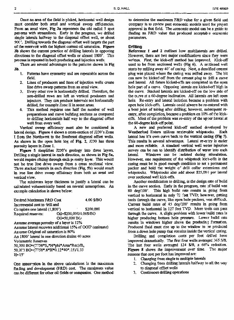
Multilateral Well C o s t Effect iveness The relative cost of tlrilliiig and ccmpleting a Y-rib -ishbone well is 1.18 times the cost of a single lateral well. Thc relative costs for otlicr wclls arc: stacked cual lateral 1.58. I :ul l \ \ i r~ dual lateral 1.67. antl the more ccimplex crow's f o ~ t triple lateral 2.54 times a single lateral v/ell. Petromata h:is found that tlie production rates gained witli these various de!;i~ns make thc investment worthwhile. 111 a general sense thi:; can be seen i i i Figurc 20 comparing sinale lateral and mL 1til:itcral well rates.
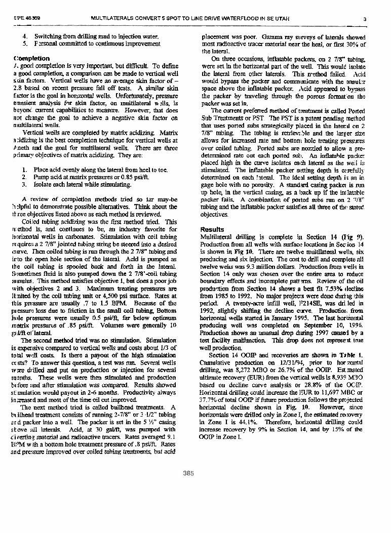
A similar result is apprirent for fishbone wclls as stiowri i i i
Figurc 21. The two earliest WS34 fishbone singl,: I:itcr.~l wells show improveti productivity relative to the othrr 14 WS3A single lateral wells. These hvo iislibone wells zppear to bave accelented recovery and still show enhanced productivity after 12 montlis of operation.
Multilaterals Allow G r e a t e r Depletion One advantage of rnultilateral wells is that the reservo r c:in be depleted to a greater extciit than single lateral well; would allow. For example. wppose that a single lateral well kis rin economic limit rate of 50 BOPD. That same Lateril vlien combined in a dual lateral configuration with an ideiitic.ll lateral in aiiother sand target might effectively produi:e cowii to 25 BOtD before reaching a 50 BOPD economic im.t for the dual lateral well. A triple 1ater:il well should allow e-ieii grcatcr rccovery.
Multilateral R i s k s Of course tliere can be risks witli multilateral wclls ri.latctl to e.xposurc to water or :ice gas. In su,:h a casc orie braiich niay jeopardize the entire well and remetiial action may be necdetf. Fortunately water is relatively predictable in this porticln of the Faja and generally can be avoided. blost free gas in .he area occurs in thin. discontinuous sand packages often sihiated adjacent to coa1 beds. Typically sucb. gas is not detectable \vitli scismic. but has occasionally showii up in limited se( ti0715 o f some horizontal and vertical wells. Operations to date indicatc that limited gas pockets of this type :)re not much conc:m.
:;['E 697.10 MULTllATERAL-HORIZONTAL WELLS INCREASE RATE AND LOWER COST PER BARREL IN THE ZUATA FIELD. FAJA. \/i:NEZUELA 5
I.lic ineclianically inore coiiiples iiiullilatcral wcll also i i i ~ y rccluirc more cxpcnsivc rcpair proccdiircs i i i ilic Iuturc. ';:iiid coiitrol 31 tlic jiiiictioiis i i i inultilatcral wclls coiild he iiiorc d.Síicult tliaii iii single lateral \vclls. but tlic Coiiipaii> Ii:is Iiac relaiivcly fe\v problcins in tliis regard :is jiiiiciioi; tl~:sigiis Iiavc e\-olvcd. l'liis by itself would he a topic Sor ri
%.t pnrait, tccliiiic:il pripci FincIIy tlie niuliilateral coiiccpt may rcsull in iiiiiial puiiip
.\< iiiiigs Iiiglicr above ilic produciioii in icn~al Ior soinc poriioiis * j ' \ tacíed iiiiiliilaicr;il wclls. .l'liis iiicrcnscd brickpi-cssurc 3:~)uld I init productiviiy o r ultiiiiatc rcccivcry lo soiiic cxlciii. ' l~\r,c\-~:r. iiiost oPtlic wclls drillcd i i i ihis opcratioii Ii:ivc iioi .~if'fcrc~! a puiiip sctiiiig clcvnlioii iiicrcnsc diic lo tlic i ultila eral desigii. For the Tcw ilirii Iiavc this protllciii, i i
,liould bc possihlc to coinpcnsate by moviiig purnps decpcr if Iicn r\ tcs are lo\\ ciiougli to sct snialler puiiips helow Llic : iizciil scctioiis.
C.oncl ~s ions l . '/arious nililiil:iicr:il well dcsiyiis liavc iiicrca\cd \veti
produc iviiy. incrcased cstimaicd uliimate rccovery pcr wcll. .i:id d<.creascd coi1 per barre1 of oil dcvclopcd iii thc I'clrozi ata opcratioii.
2 . - ' \ le lislihoiie u.cll desigii sliows proiuise of incrcasiii; I+)ng-tcriii productiviiy iii hoiiiogciieous saiids ancl inci-casiii: i.liiinaíc recovcry :iiid rate i i i Iietcro~ericous sands a,licn ribs i ross I~arricrs lo iap ~cci io i is of tlic i-cscnzoir iliai \i,olilcl ( thenvise draiii [nore slowly i fa t all.
3 . lul~iltilaieral cind íisliboiie wclls arc cxpccicd lo yicld :i
l iylicr rccovcry frictor tliaii siiiglc lateral dcvclopiiicrit by t oinbiiiiiig late lile dccliiiiiig ratcs Sroiii muliiplc iarpcts thus l c c p i n ~ ilie \vclls ahovc aii ccoiioiiiic limif ratc fnr ioiigcr l c r iod , .
4. 1-hc multilriisnil dc~.clopniciii. cspeci:illy ilic ~u l lwi i ig 11cll. r,:duces tlic ovcrall nuriibcr o f pads io draiii ihe a\.ailahlc :crea::. .l'liis reduces cosi per harrcl and cnviroiiineiiilil Iiiipaci Sor tlic proicel.
rlckni,wledgement 'i'lic a itliors a.isli !o iliaiik Pciroziiaia, ('..A. niid i i \ parciii t.onipaiiics. Coiioco Iiic. and PDVSA. for thc opporiuiiiiy to he nvolv-d in tliis pr(!ject dcvelopnieiii aiid to publisli iliis papcr.
i-'~-cdit Sor tlic iiiiiovations and produciioii rcsults prcsciitcd >cloiii, to tlie eiitirc Pct ro~uala teclitiical 2nd 111aiiayc111~11t stal'l' .atlicr tliaii thc Tcw oi'us listed as autliors.
ieferences --
l . Cla icv, 'Thoniris I'.: tielly, C.A.; Duque, Luis: "Concentric Coilcd Tjhing Wcll \'ac.uuming Technology for Coniplex I f<irizontal V'clls in E:istcrn Vcnczucla" SPE Pancr hOhOh, prcscr~icd at ttic 2000 SPF./lc(ilZ Coilcci Yuhing I<ounclt;ihlc, Iloustc,~i. 'I-'; 5-6 A pril 7000 .
2.Ciallt1way; \V. E. :irid Iloh<l;iy, O. kl., 'lcrrircnouh Clnsric I:euositionnl S\stcriis. Sprinpcr-\'crl;ig. Ic)Oli

C JOHN L. STALDER, GREGORY D. YORK, ROBERT J. KOWER. CARL M. CURllS, TONY L. COLE. JEFFREY P COPLEY SPE 6<700 --- -.
r- 7 .. . . 1
G: 1 - '~>jm? 1::~ .tGicv~, 111 ./II;~I;I r i ~ - , ; < v i ot'\ + II~:,.II,!~:I!I <\--m< c,! ! 3 , 4 [ . Tig. 2 - lntegrated operations dwmg 35-year pmject to producc and upgrade 120 MBOPD extra hea\ y mude oi l.
- -. . 1200 mete: 1200 meter
l '¡p. 3 - k i c drainape arca for two 12heter horizontal wells drilled fram a ixntralized d a c c pad
Tig. 4 - 71,Oo acre pmjtxl; TW dividcd into ~m-rnc~m hy l t w m Ter
drama@ rectanglm.
C
'S> ,'
...... F.- ~ - ~ - _ < _-. ..%.O*-" (m . -
'YJT TO ! CILE . * S : ~ . . . . ... . . 'r ,--:----m ' . . . . . . . . . . . . . . ; . , ' . " - , . ' j . , i . . ; ' & Fi?. 5 - Wcll patls, stntigraphic and horizontal wclls. and IMIO x 600 Fill. ( 3 -- !),.jr~.irio:~,d l?:i;. ici 1.: 1 )ri~.<ici~ I<ivc.t ;ii>t! c«ncqturil hl<w : rn~.tcr lrainngc rec-t;ing!rx s ~ [ ~ r i n i p o s c d on :I typicnl geoloyic setting. 111cdc.1 ~ I ' ; U I I I 51~:. litl.iol(~p! L~:vi Iog rcsp~is ,* I 'clr 3 horl/o!?Ld T!?' .

SF'E 69"OO MULTILATERAL-HORIZONTAL WELLS INCREASE RATE AND LOWER COST PER BARREL IY THE ZUATA FIELD, FAJA, I ENEZIJEU 7 -- --
Ranc:show zones of 70.30.50. and 100+ ohm-meter res~stivily G m - non-pay si. or sh:de: resistivity 4 10 ohm-meter
\ Red = ne< oil: resistivity > 20 ohrn-merm -- ---p.--- p.--.------ --- L
Vi,!. 7 - Sonw ~rcl ls <-I-cou:iier sery Iiiph quil i~y oiI hcminp. salid ,)ve1 ir~sl o':hc dnllcii scciio:~ ;is shoxvn hy 1S?7-3 hori7oiit1I 1xt.11 lo.!
l ( i ~ e n r m-pay .;¡Ir or sha e on gainiiia ra;: lo.:
Fig. S - OLi~cr wells cncounicr sliortcr iiiicrvnls >foil k ~ r i n p w ~ ~ d iv.::i
sigiiificant <ilt scctioiis as sht1.b~ hhy horizontal ncll lops froiii 1J274
N 111 - '.l.C! ?!'/ST3
' ean 14.0 '.?hLiTB
*. 1 . ,. -1 ' , . , l ... % . . x .' l!-c...i 1. B i;:i..i.;:,,rly in -;i.~. ,!c: :.; ,-í1:.,.iL. T . .,;.. Fig. IO - Distrihution ofOi l In P acc connectcd lo 1200 rnttcr latcri.~s Ir .<p; Iinp wel! con:r )I alloas accuratc: dc;h).;i~ioii.!l iiir~rpi ~~il i i i i i . with 600-meter by 1600-meter sincing.
- .
&S P e t r o w a Slngh Lateral Wdh: , /' . Cum Oil -n Effocüva bngth
Synchronloid iim. Mh Yortlm
big. 1 - Basic single lateral well with 7-inch cllotied liner, possihle Fig. 12 - Effwtive horizontal length strorgly infliiences oil productior downt ole diluent %&tip. .md ESP or PCP lift. bawd on production from 86 sin*:le laten1 wells.

3 JOHN L. STALDER. GREGORY D. YORK. ROBERT J. KOWER. CARL M. CURTIS. TONY L. COLE. JEFFREY ti. COPLEY SPE e ,7011
'ic. 13 - Vertical well 1% pay tbickness is not a consisimt iFdicaror of ioimnal well @uc:ivity bsed on 82 single laeral wells.
STA< K I D HIILTII.ATERAL WI[L.L SCHEHATlC
'IF ,y:
depth P-iV permeability temperature gravity gas oil ratio viscosity..dead vismsity..live sand character compressibility initial pressure
Fig. 14 - Reservoir pmpemes :m spical of shallom unconsolid;ited heavy oil san& in the Faja and elsewhere.
. . . - I 4.T am-xiii n í.'ümi L i . r
.. . ... .3mk"-' - z
, ~ - .. ,. m Fir. 15 -Thc ~Lackcd i'ul laknl wcll has an w r latccal uldcd Lhrwgh Fig. 16 - Thc fishbonc wcl1.i i i ' r i inlr.ri>\; pri~~ii.c: vity with highcr 3 windt>w cut in the %Si8 inchcasing of a single lamal desip. capacity cnnduiis nnd by cmirii!: tlow han1c.s n,id baniers.
l : Step @ t i ' !--:iva'opn
. . . ~ . ~ L. . - - . - .
i 6- t ig. 17 The gullwinl: u-cll accesses the dninnge rcct;in~Jes :icijacent 1:: Fig. 18 -Tliecrou '\ f~w! \fi:ct ,!(id\ a ~ c n ! r d la eril 10 a yullt.r-i i g t i ) *!io.;e crntainin? the vvll pnd saving the cost of n<l<iition;d wcll pad~i. acce.is the 730 ineter faim:~!. w w w n 1it.zls of wrlls on a ~ i : I C ~ : c ~ i i t 1 .d
:;"E 69700 MULTILATER4L-HORIZONTAL WELLS INCREASE RATE AND LOWER COST PER BARREL IN THE ZUATA FltTLD, FAJA. ' . f i N U L ELA 9
-- =' ------ I
$-
: & " i 1 I : "i : ,m;
.m;
m 1 " i
,. , , i 3 % 87
-.m, -,mi
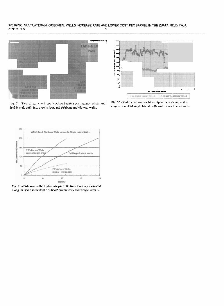
:ir,, 1'. . :t <,j; ici:rit .,::, [S are <'itz.l;~on <.,,! ith :1 <.,,:-,; n;lt,,,il i:ke<l Fig. 20 - Multilatcral wclls achi<.vc highcr ratcs s5own in ~ h i s
lunl In cnl, g~lla~ng, crow's foot, antl tishbcinc multilürcrai wells. compansoii of 9.1 single lateral ivells wirli 19 mu t i1 itrnl v.ell. .
Fig. !I - Fishbone wells' higher rate per 1000 feet of ner pay m e a s d alonl; the spine shows that ribs bmst pductivity over singlc laterals.

!Jlultilaterais Convert 5 Spgt to Line Dnve Waterffooa in SE Utah Smtt t i . HaU, SPE. Texaco North Amencan Producing West
Th!a ppn vrir pnpMd br ~~ at ~ I O 1189 8 lIn(an8ümri Cniusnu ind Ex W h l Iri Uimp hdd m Wkg. China. 2 8 N m a m h 1888.
T h . s p p e r r s r s & c ü d b ~ bymSPEPmgmfnBnnithablbwngnviewd bfiwmüon mntained in an c b m h d by he avmoii ). cmbmk tho ppa. ts ~ n s a t s d . l a s nci bwn reviavsd by ths SxieQ d Psbaleum En.3insers and are ruL-jd to cmradia, Iq ha heor(s]. The mmtuial, as pleaonted. dma mt m n l y mñeS sny ~ u ~ i ü m a t i h e ~ o i P e b d e u m E n g i w e r r , L ~ w ~ R p e i a ~ P t E F E m e d l i ~ u r J u b p d h > , p i ~ ~ & E d i h < i d C o m m d t . . . d ( h . ~ o f F a m m Iñgine~. Eisc(mivc mpoductiai. dmiion, a .bong. d any pad d (tli pppar Pxoommidpurpprwiihwithwittmamssn<of the SocldydPsbdmurnEn(l-tr ~ f f hibaed 20- t~ ropmduw in plnt is resbkhd b an abrtact d no(: m m h n 3M1 vard3; rn6hhtk7 msy noc b. c+ed Th. nhtn.3 mvst mnWn cu!+xus a c ~ ! m a t r 4 - . n d b y * h a n t h p i p s i . 4 1 p n m t s d . ~ L l ~ S P E P . o . t b n E 3 Q f l . Wdurrtrrn.TX-. U.SA.fiaO14724624435 -- - r l bstra.ct 1-lon.7~1ital technology has i n m e d rapidIy since the late :!!180's. Most horizontai wells drillcd in the U.S.A. have been ir. prianary recovery applications. However, horizontal leduiol~gy can be modified and appüed to secondary recovery ol~ernti(ms to -ve sweep efficiency and recovery over 7, :.rtical wells.
Thi:; case history reviews four y m of a mdtilateraí 1ic)rizontal drilling program at the Aneth Unit and updates Ref :l and ;:. Multiiateial drillig has amverte. parts of the Aneth iJnit film 5-spot to line drive waterfiood palienis. Drilling I~~~tizoniai in both producing and injection wells with laterals p.uallel to each otha may improve oil recovery by 15% of the C0iP in the zones horizontaliy ctrüled at the Aneth Unit :!Iowever, not al1 zones and not aii parts of the field are :.xnonuc for horizontal drilling. Fmm late 1994 h u g h ~zuiy 1998, 143 laterals were drilled and. compieted as re- citries h m 43 vert id wells (23 produchg and 20 injection). 'Those 43 wells were drilled 214,000 fed from kick-off to total .Irpth, Of the 214,000 feet drilled, 180,000 feet was pay. Ail 3 79 prwious vertical wells drilied only 26.000 feet of pay. t:orizontal drilling exposes IMg~tudeS more of the pay zone to the ~vdbore.
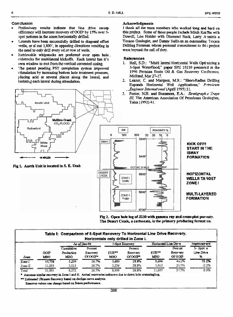
Iiittoduction Pseth unit is locateti in souiheast Utah (Fig 1). Prior io horizo~itai drilling, Aneth Unit oil recovery as of December 1994 vvas 300/a of thc original oii in place (GOiP) and ihe projecird uiiimaie oil recovery was 35% of WIP. Mast productioo comes fmm the Pexmsyivanh Desert Creeh Formaion The Desert Creek is a murti-layered carbonate rservctir. A typical open hole garrnna ray and porosity log is s hown in Fig 2.
The D e . Creek is divided into two separate prtidui:ing horizons dled Zone 1 and Zone 11. Zone ii was deposited primady as phyloid alp l moimds. Permeability in ;!one 11 varies from .1 md to-ayer 5- md Zcne ii produces hir* ililiti volumes at low oil cuts due to high pmeabiIlty anii waterfloodhg sin- 1962. Zone ii i.i currcntly produ ;tive iii isolated b&ns
Zone 1 has iower permeabilíty resuiting in higher aumt oii sahrration than Zone Ii. Zone 1 WIS deposited as ar oclitic limestane &al, like ihe beaches ar mnd the Bahamas, Zone I t& to have udimi but low pameability r tswv3irs
Additional geoiogic datñ can be founrl in Ref. 3. The werage effective permeabiiity tn Zone 1 is 1 md. Zone 1 is slill producbive everywhere in h e field
Zone 1 contains 65% of the OOCP and Zone ii conlains 35% of the OOiP. Recovay and injcAion from mch zme oxi o d y be esiimated because production and mjecton are commingled down hole. Because of the higher airrcn? oil satination, laterals have only been driUed urto Zone L
Aaeth has typical light oil properiies. Wscosity of the 41" API gravity oil is 0.53 cp at a bubble point pressure tf 1,739 psi. The soiution gas oil ratio is 64:; CF/BO at bubble pciint pressure. Current reservoir pressures v i q cue t~ watdooding bui the average is 2,700 psi.
Desig n Design started with pidgng an area of !he field to hori ~ontally drill. Tbe two primary caiteria consirlered were OOP ¡n ;'me 1 and curruit oil recovay as a percel of O I P High COIP and low recovery was preferred. Baiied on the above cxii&a, an area around Section 14 was pickei and horizoníaiiy milled first Results of Section 14 are presexited later m this piger.
AFter Sedion 14, an area a-ound Section :!G was horizontally drilled. Section 26 5s lower Zone 1 03E' bid higher current oil SHmtion based on lower oil nmr-r. Early resub, shown below, indicate recovery may-be ino1.e important tiian OOIP. The m o i i in Seciion 26 has lmt!r permeability ihan Section 14. However, í n d recovay b m horizontal weiís ia Section 26 t a n not y d be det&ed due to the limited pradiiction history.
Zone 1 OOP Current Rec. Avg. HO& [P Arca MBOIWeil _ % of OOP BOPDIBWIISZ .
Sec. 14 1,232 27% 2741930 Sec. 26 930 lP! 433/454
2 S. D. HALL SPE 46- - --- Once an arca of the field is pickcd, horizontal weil design
mun consider both ared ami verti01 sweep effíciencies. Fmm an areal view, Fig 3a repments the old radial 5 spot p a n s with stradhes. M y in the program, we Mled <mide lataais h a h a y to the diagonal oiiset well, or about 90Cr'. W i n g towards the riiagonai offset weU targcts the part of the reservo& with the highest current oii saturadon. Figure 3b shows the current practice of driiiing laíerais in opposiag dindons to the diagonal offset w e h or almost 1800'. This process is repeated m both producing and injection weüs.
Thm are severa1 &antages to the pattcms shown in Fig 3b.
1. Patterns have symmetry and m repeatable amss the field.
2. Lines of producers and bes of injection welis create line drive sweep patlems ñom an areal view.
3. Evay other row 1s horfiontaiiy drllled. Therefore, the non-drilled rows are left as vertical producers and injectors. They can produce intervals not horizontally driiled, for example Zone II in som areas.
4. This metñod requires one half the d e r of well preparations and curve building sections as compared to dRlling hoiizontals haif way lo the diagonal offset well h m every well.
Vd& sweep aciency musí also be considered in lateral desiga Figure 4 shows a cross-section of J2307s Zone 1 ñom the Norih~vest tu the Southeast diagonal offsel weh . As shown in the open hole iog of Fig. 2. J230 has three porosity layers inZone 1.
Pignrc 5 cimplifies J230's geology mto . h e layeis. DrjUUig a súigie lateral in each direction, as shown in Fig Sa, wodd require sücing through each pc:rosity laya. This would not be tm lme drive sweep from a m s s sectional view. Thiw siacked !aterals in each direction (Fig. 5b) would result in me h e drive sweeg efficiency from both an areai and verticai view.
The mjnimum laya thiches to justify a lateral can be caí13ulaíed volumetricaiiy based on several asmnptiolls An a m p l e calailation is shown below:
De- Maximrun F&D Cost 4.00 $/BO Incrementai cost to .Irill and Co nplete one lateral (1,800') %200,OOO Ret~uired reserves: Oil=$200,000/4.00$iB0
Oi=50,000 BC, h m e average porosity of a layer is 12% Asume lateral recovers additional 15% of OOIP (eshate) &,ame Origmai oil satination is 80% An 1800' lamd in one direction drains 40 acres Vo 1umeh-k Resaves 50,000 BO=(7758*S,*H*phi*Area*Rec)/BD 50,OC3 B0=(7758*.8*H*O. 12*40*. 15Y1.33 H= 15'
One assumtion in the above caiculaíions is the maimum fíu~iing and development (F&D) cost The mauMum vaiue mi be diffe~em for other oil fidds or companies. One method
to detumine the maxhum F&i> value for a given field imd company b lo review past econc~mic models useif fm pmject approval in that field. The cconomic model can be a pide: to fin* an FgtD value that plixiuccd acceptab e rxo~noimc parameters.
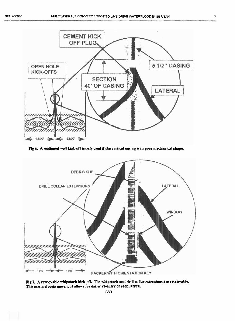
Drilling Referentx 1 aad 2 outlines how multilaterals m drilled. Howwer, there are two major modifxatioris since tky were wr-tten F i i the kickaff method has improved. Kick.off used to be fiom sectiooed weiis (Fig ó). A se3ticned vreU síarts by milling away 40' of cxng. Next, a densified menl plug was placed where the casing was milled añay. The bit can now be kickd-off fiom the cemait plug to Mi a curve and l a t a Aii fuhm kicked-offs are completed in the qíen hole part of a m e . Opposing aterals are kicketi-off higti in the curve. Stacked laterals are Iricked-off on the low side. of the nrve at a óOdegree inciiit:on. Aii lateds :m lefl o lm hole. Re-entry and lateral isolzition became a problem with open hole kick-oík Latffals could always be re-entcseri ~ i i h a bent joint of tubing af ta dnlling, howevq subsequmt re- mny, after mmpletioo, became a pmblem on 10% of t k kick- offs. Most of ihe problem was re-entry of the upxr 1;atml at the 60degree kick-aff point.
A new aod preferred kicl:-off method dcveloped by Weatherford Entera utiiizes rerrievabie whipstccks. E d lateral has it's own nave back lo the vertical (Fig 7). This resuits m sevaal advantages. Lateral reatxy is =Ser and more ~Eable. A standard vertical well water injedion survey can be nm to identify dküibution of m e r "mto elch i a t d Wrndows can be isolated during stimdatlon However, one reqilirement of tiie whipstock kic'c-offs is the casing m s t be m good enough condition to set a pennanent packer and hold the weight e' dril1 collar extenaions :md whipstocks. Whipstocks also add about $25,001) per i a t t d over sedioned well kick-offs.
Another modificarion to drillmg, is tlie design rmc: of bidd in the a w e section Eariy in tlie prograta, rate 3 f l d d liras 80 deg/10OY. This high build rate res& in gobg h m vertical to horizontal m only 7; W, however, gating tools through túe curve, like opcm hole packers, \vias c!iíEcdt Current build rates of 45 deg/100' results in going fiom vertical to horizontal in 127 feet TVD. More taols can j!ass through the curve. A siight prot)lem with lower lniild mes is higher producing bottom hole pressure. Lowtr buM late results in wmdows higher above the producin : formation Produced fluid miist rise up to the window to 3e produced from a down hole pump that rernains inside the verticat mng.
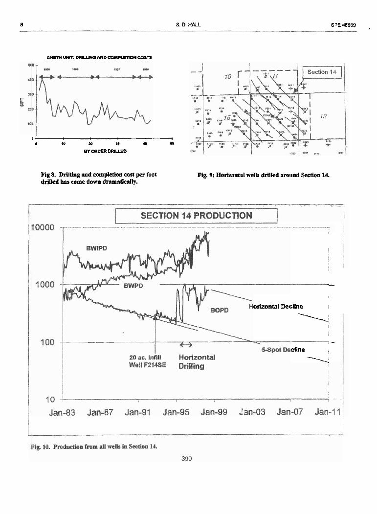
Drilling and completion costs per foot tiriíled hwe impruved dramatimlly. The fm! four wells averaged 365 YJR The last fonr wells averaged 124 S/% a 66% icchiction Figure 8 shows the improven~ent over time. The mijor reasons that coa per foot has iny~roved are-
l . Chaaging h r n single to dtq>le l a t d s 2. Changing From driilhg laterais halfway B) al1 the ivay
to diagod, offset wells 3. Continuous drilling opaations
E PE 48 389 MULTILATERALS CONVERT 5 SPOT TO UNE DRlVE WATERFLOOD IPI SE UTAH 3 -- --
4. Swit&ing h m driiüng mud tc~ injection water. 5. F xsonai committed to continwus improverni=nt
C:ampletion 1, gootl completion is vety imponan~, but diñicull. To define a good wmpletion, a cornparison can be made to vertical weii isin fkctors. Vnticai wciis have an average s h factor of - 2.8 baied on recent pressure fa11 off tests. A similar skin fiiaor is the goal in homntal wells. Unfomnateiy, presnire bansiaa analysis fm skin factor, on multiiatenl ñ :Us, is beyoni m t crpabilities to measure. However, tbat does not chmge the goal to xhieve a negaüve skin factor on n idtila temi w d s .
Vaticaí wells are compleied by matrix acidizing Mauix a 1dizi11g is the best completion technique for vertical weUs at Pneth and ihe goal for muidíaleral weUs There are t h e p r i w r objedñres of mairix acidiz'ig They are;
1. Place acid cvenly along the lateral h m hcel to loe. 2. Pump acid at d x pressures or 0.85 psüft 3. Isolate each lateral while stimuiating.
A itview of completion rnelhods tñed so lar may-be lit:lpful to demonsúaie possible altematives. lñink about tbe lfree 01)jedíves Iisted above as each method is reviewed.
Coiled tubing acidizing was the ñrst method tried. This ixethod is, and continues to be, an industry favorite for Iiorimntd wells in carbonates. Stimulation with coi1 tubmg rcquhz; a 2 7/8" jointed tubing &g be steered into a desired ame. Iben coiled hibing is m through the 2 718" tubing and ia to h e open hole section of the latemí. Acid is pumped as the coi1 tubing is spooled back and forth in the lateral. tE)metiines fluid is also pumped down the 2 7B'coil tubiig ;uunilus. Thj.s method satísfies objedive 1, bnt does a poor job with ol,jectives 2 and 3. Maximnm treating p m m e s are lkzifted by the coii W i g unit or 4,500 psi smfáce. Rates at ibis pnssure are u d y .7 to 1.5 BPM Because of iiie plessun: loss duc to fiiction in the sman coíI tub i i Botlom holc presmes wat usually 0.5 psitff far below optimum inatrix pressurcs of .8S psim Volumes were generally 10 g ~ i l í f t oi'laterai.
The second method tried was no stimdation. Stimulaton is expexwe corupared to vertical w e b and costs about 1/3 of tohi w19i costs. 1s thm a payout of the high s h u h i a n cr'sts? 'To answer this question, a test was nm. Several wells nxe diüled and put on production w injection for several roonths. These weils were then Shdated and producdon titfore imd after stimulaiion was mmpared. Results sliowed stimulation would payout in 2 6 months. Productivity always i n ¿rmse d and most of thc time oil cut impmvd
The next method bid is called builhead treatments. A hilihea<l treatment consists of nmning 7-718" or 3 Y2" tnbing es d packer into a weil. l ñ e packer is seí in the S %" casing ~tove ílll i a t d . Acid, at 30 was pumped with c i vertin 5 rnatenal and lrdioadive tracers Rates avemged 9.1 BPM w ith a bottom hole matment pressure of .8 psüR Rates and p r e : m improved over coiled tubing tre3tmenb. bu1 a ~ d
placement was poor. G a . ray nirveys of laterais choweii most xadioactive mcer material near the h e 4 or ñrst 3006 of the lateral. On three occasions, ir-tEiatabIe packexs. on 2 718" tnMnp,
were set m the horizontal part of the weil. lhis woulc isolatc &e lataal from other laterals. This rlretbod failed Acid would bypm the padca and commiaiicatc with thc uznulir space above the inflatable packer. Acid appeared to b p , the packer by traveling b u & the porous formaton thi: packer was set in
The current p r e f d method of treatment is callad Ported Sub Tredments or PST ?he PST is a patent pending melhod that uses ported subs smegically placed in the latemi on 2 718" lubing. The tubing is retriev¿3le and the larga size allows for m m e d xate and bottoni hole treating p r e s s ~ ~ wer coiled tubhg. Ported subs are n d e d to aiiow a DE-
detcrmincd nte out each ported suti. An inflatahle patker placed high in the curve isolates ea& lateral as the weil is stimulated. The infiawble padcer s15ting depth is auefully detennined on each '%eral. The ided i i g depth i s a11 ie gage hole with w poro*. A standmi casing packa is m up hole, m the vertical casing, as a I~ack up if the imlatltrle packer fails. A cambination of ported subs nm on 2 '7/8' ' tubing and the inflatable packer satisfies al1 tlJree of the stuird objectives.
Resuits Multilatcral dnlling is complexe u1 Section 14 @'ig 9). Production from aü wells with d a c e locations in Secion 14 is shown in Fig 10. There are twelve multilatd weiis, six producing and six injection The cost to dril1 and wmp lete al1 twelve wehs was 9.3 m¿%m dollars. I'Jrochction h m vrell3 i . Section 14 only was diosen over the entire area to reduce bounáary effeds and incomplete patt m. Review of the oil produ.ticm fmm Sedon 14 shows a best fit 7.53% tiec]:he fmm 1985 to 1992. No major projecs werc done dini.= i-his period. A twenty-acre infiii wd, 1?214SE, was driJed io 1992, sl@Uy shifting the dacliuc ctme. Producfio~i h m horizontal weih statted in January 1995. The last hor&iztal producing well was completed on September 10, 1996. Production sbows an unusual drop di* 1997 causei by a test f- rnalfunctíon This dmp does not represeit tnie weii production
Section 14 OOIP and recoveries are shown in Tsbk 1. C d a t í v e prodncfíon m 12BIf95, prior to horz~iüal ciriiiing. was 8272 MBO or 26.7% of the 00iP. Estmated ultimate recovery (EUR) h r n the vertical welis is 8,939 M30 based on deciine m e analysis or 28.8% of the OCiP. Horizontal driiling could increase the 13JR to 11,697 MBC or 3 7.794 of total OOlP if fnhne producti~m follows the prr$ectd horizontal decline shown in Fig. 18. Howeva, suice horimntals were driiied oniy in Zone 1, the estimated mx)very in Zone 1 is 34.1% nierefore. horizontal dñiling codd increase recovery by 9% in Section 14, and by 15% of h e OOP in Zone 1
4 S. D. HALL SPE 48B(j9 - --- Con clusion Acknowledpments
I'reliminary rcsults indicate that liue drive sweq 1 thank al1 thc teani rncmbas who workd long and hard on ~Sciency will i n m e recovery of OOIP by 15% wer 5- this pmjea. Some of h s e peaple ixhck Mitcii KniSm wi"h :pot pattems in the mes horizoniaiiy drilled Dowell, Lou Holder wüh Diarnonri Back, Lany Anateis a Initerals have been successfuíiy Qilled to diagonai offset Teyaco Geologist, and Darmy Sulliwn an outstandin~ Tcxacx, wells, or al out 1,800', in opposing directions mdting in Drilhg Foreman whoe pexsonai o~mmitment to thi ; project Ihe need to only dril1 every 0 t h row of wek. want beyond the cal1 of duty. lletrievable wbipstocks an p r e f d over opai hole . (idetradcs for multilateral kickoffs. Each l a t d has it's References (m wi&w to exIf ñom the vertical cemented casing. l. Hall, S.D.: "Muiti lateral Horizontal Weils Optinizing a 'íñe patent peoding PST completion system iraproved 5-Spot Waterflood," peper SP13 35210 presented at die !;timuiation by mcrcasing bottom hole treaímen! pressmre, 1996 Permian Basin Oil & Gas Rewvery Corference, placing acid at several places along the laterai, and Midiand, Mar 27-27. isolating ea& lateral during stimuiation 2. Leazer, C. and Matquez, M.R.: "Sha-Radius Diillirig
Expcpands Horizontal Weil Applicatioa~" P~~hoIcarn . .figineer lntemaPonaI (April 1!)95) 2 1.
3. Foster. NH. and Bealtmont, E.A.: Shfigraph c 5"raps
P UI, The American Associalion Oí Petroleurn Geologists, Tdsa (1992) 41.
M c E h C r r k
KlCK OFFS START 1N 1'HEi ISMAY - iomuis - FORMATION
Fig 1. Aaeth Unit u lo~eted in S. E. Utab
HOFIZONTAL WULS TA'3G ET ZONE l
MULTI-LAYERED FORMATIOM
Fig 2. Open bole log a l J230 witb gamma rag and cmss-plot porimdy. The Desert Creek, a cubanate, u the primary pmducing format oin.
1 Table 1: Companson of SSpot Recovery To Horizontal Line Drive Recof~ery. 1
t Hoñzontals only drilled in Zone l. I
As of Dec-94 S-Spot Recovcry Horiwd Lim Dri*re - Irrqnworront Cumulmive P m t R m t ~ a n r 5 Spot 7
OOP Producben Rccovery EURm* Recovay ELR** Reto-fory Line Dh e Zoae - MBO MBO OfOOlP M E 0 Of 00P MBO OfO3IP -- %
Zonc I 19,708 5259 26.7% 5,683 28.8% 8,684 41.1% 15 2%'
ABsrmia similar m v a y m Zona 1 and 11. Aciuai rccoveries unkwwn dw to down hole commingling. ** E s t i 4 Ultimde Rscoveiy bPssd oa dsciins curvs Prulysk.
Raerves valvcs can cbsnge b a d on fvain @m-. --. 386

3 ' r E -9 MULTIIAERALS CONVERTS SPOT TO UNE DRlVE WATERFLOOD 1N SE UTAH 5 -- - --
TYPiCAL SECTION 40 ACqE WEU-
SPAC ' 10
Fig 3a. The old way with 80 acre 5-spot prtterna Fig 3b. Horizoataiiy drilled line drive pattenu from 5-spots Lme chive patterna that could Impmve movery by 15% oí* 001' in the zoma h o h n t a l i y drilled. Ndice tfilt only every ot&r row is horhntaiiy drilled
Fig 4. Aneth Unit J230's cmrm-sectioa sbowing thrte layen of pay in Zone L CroJs-section goes from diagonal offsed H125 to -0.

6 S. D. HALL ;PE llSES36ci - ---- .
DEPTH
5,500'
1,866' 1,866' -- Fig Sa. Oae lateral M e d in each diredon would not be Iíae drive sweep efficiency from a cross section vi-.
Fig 5b. T h m stackcd lateral~ ia each direction provide trw line drive sweep eíííckncy in eacb vertical layer.
388
SFE 488690 MULTTLATERALS CONVERT5 SPOT TO LlNE DRlVE WATERFLOOD IN SE UTAH 7
Fig 6. A sectioned well kickaff is oaly used Xthe vertical casing is in poor mechaoieal shape
Fig 7. A rctrievabk wbipstock Irick-ofí. The whipsioek and driU coiiar extemions are retrkvabk. Thii method cosa more, but d o w s for easier re-enby of ea& MeraL
389
8 S. D. HALL S'E4-5869 ,
ANETH U W W N a AND CQSTS
1 4 I
O 10 20 m 10 W
BY ORDW DWUED
Fig 8. D m g and completion cost per foot Fíg. 9: Horizontal wdls drilled anuind Section 14. driJied has come down dramaticaüy.
I
' ! [
L
1
orizontal Dedine ,
1; ! 1 I
i -
cline !
\!