Embed Size (px)
Citation preview
2CD
C 2
51 0
62 V
0011
Data sheet
Multifunctional three-phase monitoring relays CM-MPNCM-MPN.52, CM-MPN.62 and CM-MPN.72
The three-phase monitoring relays CM-MPN.x2
monitor the phase parameters phase sequence,
phase failure, over- and undervoltage as well as
phase unbalance.
All devices are available with two different terminal
versions. You can choose between the proven
screw connection technology (double-chamber
cage connection terminals) and the completely
tool-free Easy Connect Technology (push-in
terminals).
Characteristics – Monitoring of three-phase mains for phase sequence (can be switched off), phase failure, over- and undervoltage as well
as phase unbalance – TRMS measuring principle – Automatic phase sequence correction configurable – Threshold values for over- and undervoltage as well as phase unbalance are adjustable as absolute values – Tripping delay Tv can be adjusted or switched off by means of a logarithmic scale (0 s; 0,1-30 s) – ON-delayed or OFF-delayed tripping delay selectable – Powered by the measuring circuit – Precise adjustment by front-face operating controls – Screw connection technology or Easy Connect Technology available – Housing material for highest fire protection classification UL 94 V-0 – Tool-free mounting on DIN rail as well as demounting – 1 x 2 or 2 x 1 c/o (SPDT) contacts configurable – 45 mm (1.78 in) width – 3 LEDs for the indication of operational states
2 - Multifunctional three-phase monitoring relays CM-MPN | Data sheet
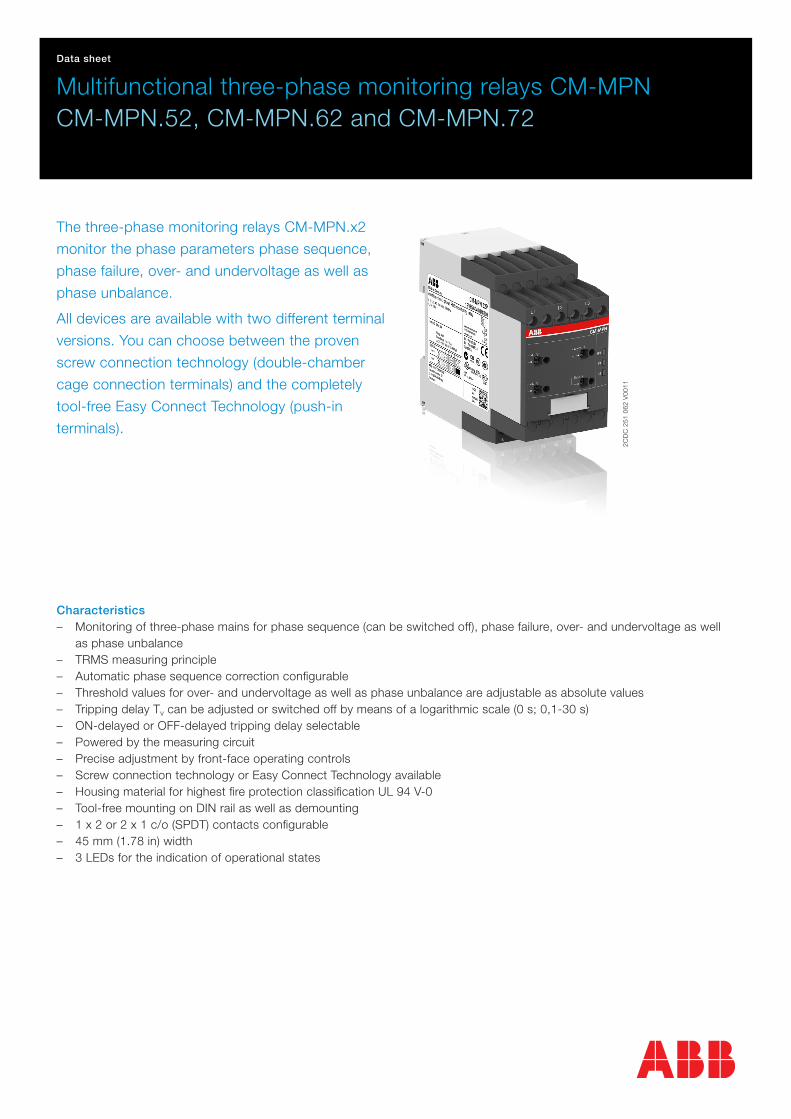
Order data
Three-phase monitoring relays
Type Rated control supply voltage = measuring voltage Connection technology Order code
CM-MPN.52P 3 x 350-580 V AC Push-in terminals 1SVR760487R8300
CM-MPN.52S Screw terminals 1SVR750487R8300
CM-MPN.62P 3 x 450-720 V AC Push-in terminals 1SVR760488R8300
CM-MPN.62S Screw terminals 1SVR750488R8300
CM-MPN.72P 3 x 530-820 V AC Push-in terminals 1SVR760489R8300
CM-MPN.72S Screw terminals 1SVR750489R8300
Accessories
Type Description Order code
ADP.02 Adapter für Schraubbefestigung 1SVR440029R0100
MAR.12 Beschriftungsschild für Geräte mit DIP-Schalter 1SVR730006R0000
COV.12 Plombierbare Klarsichtabdeckung 1SVR750005R0100
Data sheet | Multifunctional three-phase monitoring relays CM-MPN - 3
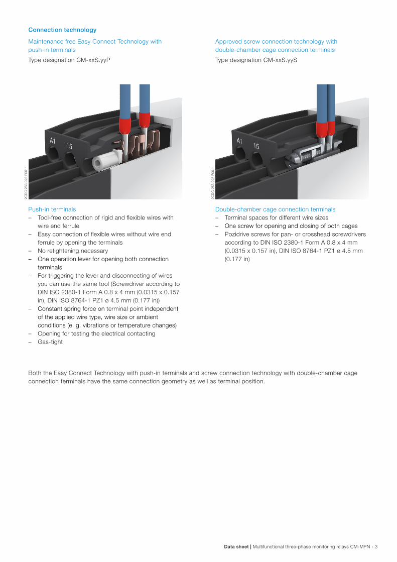
Connection technology
Maintenance free Easy Connect Technology with push-in terminals
Type designation CM-xxS.yyP
Approved screw connection technology with double-chamber cage connection terminals
Type designation CM-xxS.yyS
Push-in terminals – Tool-free connection of rigid and flexible wires with
wire end ferrule – Easy connection of flexible wires without wire end
ferrule by opening the terminals – No retightening necessary – One operation lever for opening both connection
terminals – For triggering the lever and disconnecting of wires
you can use the same tool (Screwdriver according to DIN ISO 2380-1 Form A 0.8 x 4 mm (0.0315 x 0.157 in), DIN ISO 8764-1 PZ1 ø 4.5 mm (0.177 in))
– Constant spring force on terminal point independent of the applied wire type, wire size or ambient conditions (e. g. vibrations or temperature changes)
– Opening for testing the electrical contacting – Gas-tight
Double-chamber cage connection terminals – Terminal spaces for different wire sizes – One screw for opening and closing of both cages – Pozidrive screws for pan- or crosshead screwdrivers
according to DIN ISO 2380-1 Form A 0.8 x 4 mm (0.0315 x 0.157 in), DIN ISO 8764-1 PZ1 ø 4.5 mm (0.177 in)
Both the Easy Connect Technology with push-in terminals and screw connection technology with double-chamber cage connection terminals have the same connection geometry as well as terminal position.
2CD
C 2
53 0
25 F
0011
2CD
C 2
53 0
26 F
0011
4 - Multifunctional three-phase monitoring relays CM-MPN | Data sheet
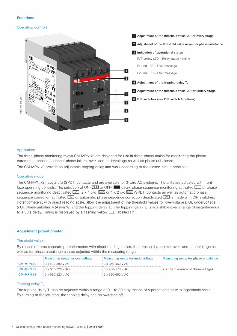
Functions
Operating controls
2CD
C 2
51 0
62 V
0011
1 Adjustment of the threshold value >U for overvoltage
2 Adjustment of the threshold value Asym. for phase unbalance
3 Indication of operational states
R/T: yellow LED – Relay status / timing
F1: red LED – Fault message
F2: red LED – Fault message
4 Adjustment of the tripping delay Tv
5 Adjustment of the threshold value <U for undervoltage
6 DIP switches (see DIP switch functions)
Application
The three-phase monitoring relays CM-MPN.x2 are designed for use in three-phase mains for monitoring the phase parameters phase sequence, phase failure, over- and undervoltage as well as phase unbalance.
The CM-MPN.x2 provide an adjustable tripping delay and work according to the closed-circuit principle.
Operating mode
The CM-MPN.x2 have 2 c/o (SPDT) contacts and are available for 3-wire AC systems. The units are adjusted with front-face operating controls. The selection of ON- A or OFF- B delay, phase sequence monitoring activated k or phase sequence monitoring deactivated l, 2 x 1 c/o i or 1 x 2 c/o j (SPDT) contacts as well as automatic phase sequence correction activated m or automatic phase sequence correction deactivated n is made with DIP switches. Potentiometers, with direct reading scale, allow the adjustment of the threshold values for overvoltage (>U), undervoltage (<U), phase unbalance (Asym %) and the tripping delay Tv. The tripping delay Tv is adjustable over a range of instantaneous to a 30 s delay. Timing is displayed by a flashing yellow LED labelled R/T.
Adjustment potentiometer
Threshold values
By means of three separate potentiometers with direct reading scales, the threshold values for over- and undervoltage as well as for phase unbalance can be adjusted within the measuring range.
Measuring range for overvoltage Measuring range for undervoltage Measuring range for phase unbalance
CM-MPN.52 3 x 480-580 V AC 3 x 350-460 V AC
2-25 % of average of phase voltagesCM-MPN.62 3 x 600-720 V AC 3 x 450-570 V AC
CM-MPN.72 3 x 690-820 V AC 3 x 530-660 V AC
Tripping delay Tv
The tripping delay Tv can be adjusted within a range of 0.1 to 30 s by means of a potentiometer with logarithmic scale. By turning to the left stop, the tripping delay can be switched off.
1
3
2
4
5
6
Data sheet | Multifunctional three-phase monitoring relays CM-MPN - 5
Indication of operational states
LEDs, status information and fault messages
Operational state R/T: LED yellow F1: LED red F2: LED red
Control supply voltage applied,
output relay energizedV - -
Tripping delay Tv active W - -
Phase failure - V W
Phase sequence - W alternating
Overvoltage - V -
Undervoltage - - V
Phase unbalance - V V
Adjustment error 1) W W W
1) Possible misadjustments of the front-face operating controls:Overlapping of the threshold values: The threshold value for overvoltage is set to a smaller value than the threshold value for undervoltage.DIP switch 3 = OFF and DIP switch 4 = ON: Automatic phase sequence correction is activated and selected operating mode is 1 x 2 c/o (SPDT) contacts.DIP switch 2 and 4 = ON: Phase sequence detection is deactivated and the automatic phase sequence correction is actived.
Function descriptions / diagrams
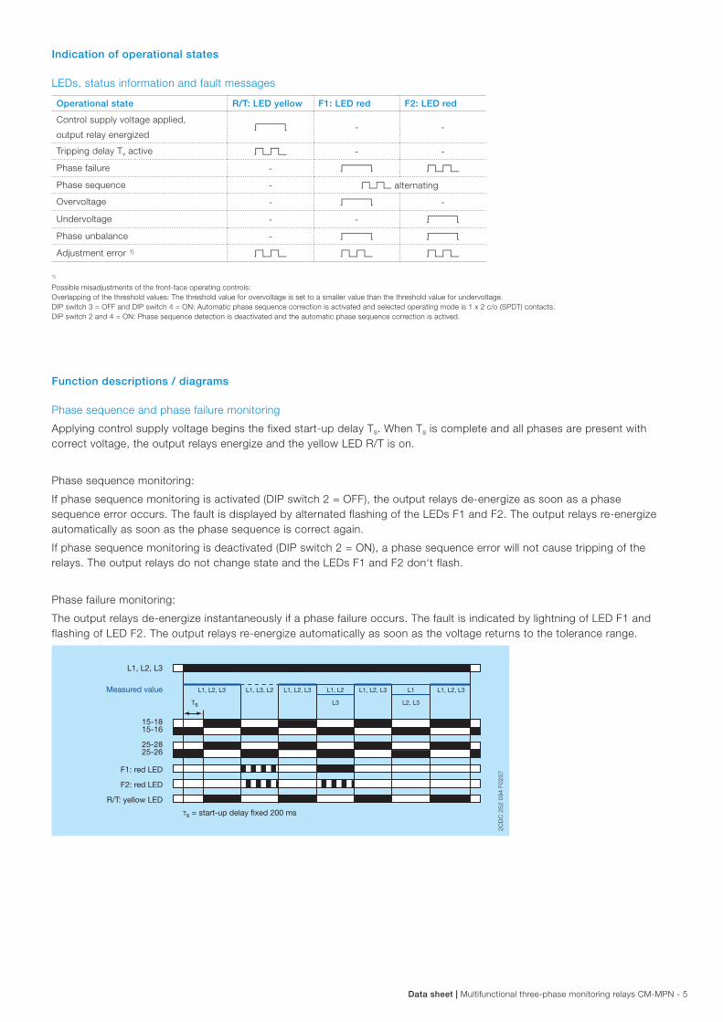
Phase sequence and phase failure monitoring
Applying control supply voltage begins the fixed start-up delay Ts. When Ts is complete and all phases are present with correct voltage, the output relays energize and the yellow LED R/T is on.
Phase sequence monitoring:
If phase sequence monitoring is activated (DIP switch 2 = OFF), the output relays de-energize as soon as a phase sequence error occurs. The fault is displayed by alternated flashing of the LEDs F1 and F2. The output relays re-energize automatically as soon as the phase sequence is correct again.
If phase sequence monitoring is deactivated (DIP switch 2 = ON), a phase sequence error will not cause tripping of the relays. The output relays do not change state and the LEDs F1 and F2 don‘t flash.
Phase failure monitoring:
The output relays de-energize instantaneously if a phase failure occurs. The fault is indicated by lightning of LED F1 and flashing of LED F2. The output relays re-energize automatically as soon as the voltage returns to the tolerance range.
25-2625-28
L1, L2, L3
15-1615-18
L1, L2, L3 L1, L2, L3 L1, L2, L3 L1, L2, L3L1, L3, L2 L1, L2 L1
L3 L2, L3Ts
2CD
C 2
52 0
94 F
0207
F1: red LED
F2: red LED
R/T: yellow LED
Measured value
Ts = start-up delay fixed 200 ms
2CD
C 2
52 0
94 F
0207
6 - Multifunctional three-phase monitoring relays CM-MPN | Data sheet
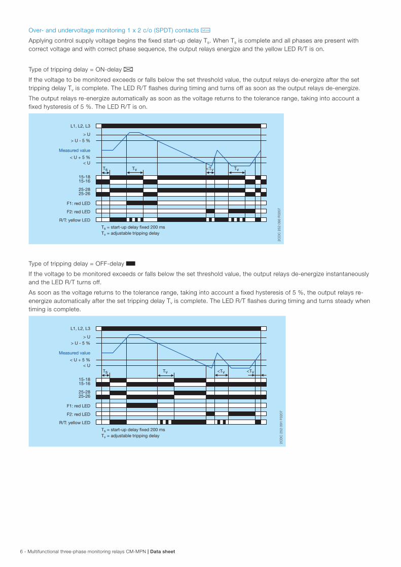
Over- and undervoltage monitoring 1 x 2 c/o (SPDT) contacts j
Applying control supply voltage begins the fixed start-up delay Ts. When Ts is complete and all phases are present with correct voltage and with correct phase sequence, the output relays energize and the yellow LED R/T is on.
Type of tripping delay = ON-delay A
If the voltage to be monitored exceeds or falls below the set threshold value, the output relays de-energize after the set tripping delay Tv is complete. The LED R/T flashes during timing and turns off as soon as the output relays de-energize.
The output relays re-energize automatically as soon as the voltage returns to the tolerance range, taking into account a fixed hysteresis of 5 %. The LED R/T is on.
L1, L2, L3
15-1615-18
> U> U - 5 %
< U + 5 %< U
Ts Tv Tv<Tv
25-2625-28
2CD
C 2
52 0
90 F
0207
F1: red LED
F2: red LED
R/T: yellow LED
Measured value
Ts = start-up delay fixed 200 msTv = adjustable tripping delay
2CD
C 2
52 0
90 F
0207
Type of tripping delay = OFF-delay B
If the voltage to be monitored exceeds or falls below the set threshold value, the output relays de-energize instantaneously and the LED R/T turns off.
As soon as the voltage returns to the tolerance range, taking into account a fixed hysteresis of 5 %, the output relays re-energize automatically after the set tripping delay Tv is complete. The LED R/T flashes during timing and turns steady when timing is complete.
25-2625-28
L1, L2, L3
15-1615-18
> U> U - 5 %
< U + 5 %< U
Ts <Tv<TvTv
2CD
C 2
52 0
91 F
0207
F1: red LED
F2: red LED
R/T: yellow LED
Measured value
Ts = start-up delay fixed 200 msTv = adjustable tripping delay
2CD
C 2
52 0
91 F
0207
Data sheet | Multifunctional three-phase monitoring relays CM-MPN - 7
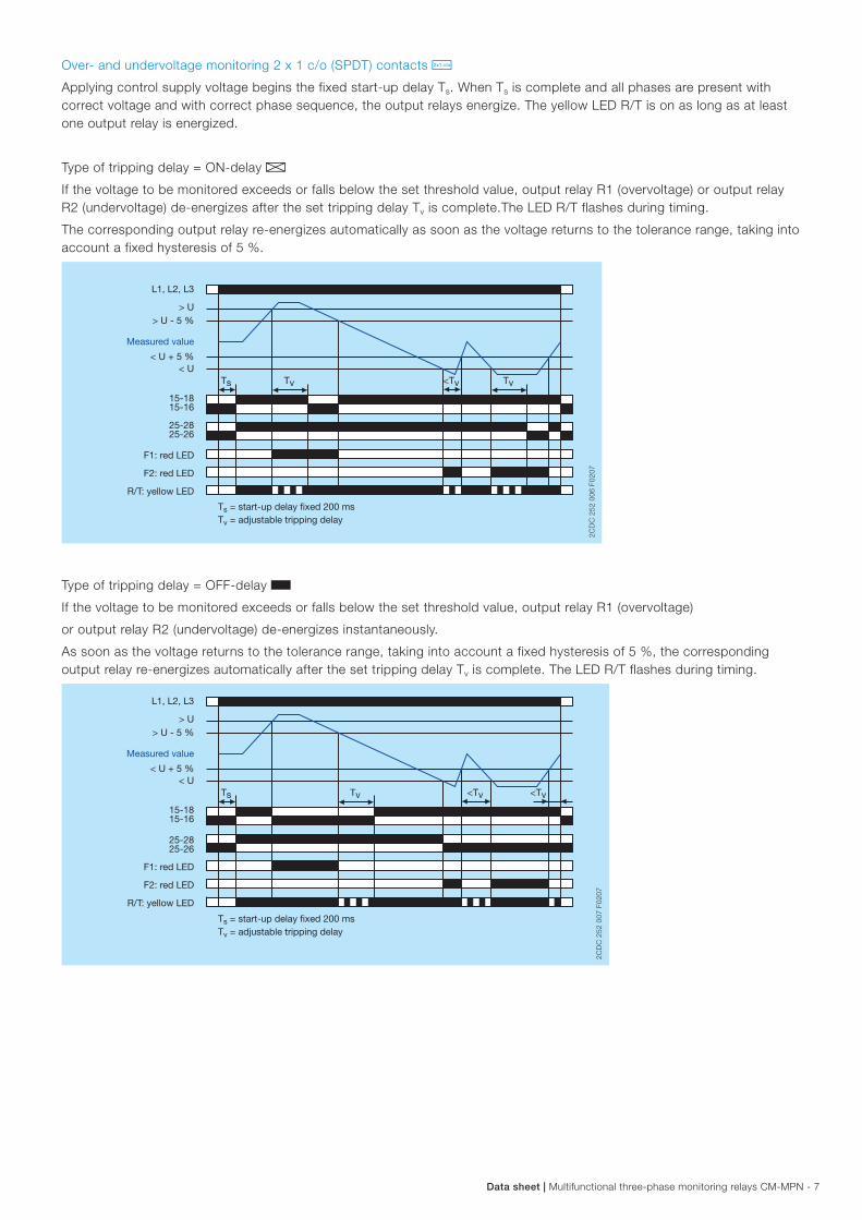
Over- and undervoltage monitoring 2 x 1 c/o (SPDT) contacts i
Applying control supply voltage begins the fixed start-up delay Ts. When Ts is complete and all phases are present with correct voltage and with correct phase sequence, the output relays energize. The yellow LED R/T is on as long as at least one output relay is energized.
Type of tripping delay = ON-delay A
If the voltage to be monitored exceeds or falls below the set threshold value, output relay R1 (overvoltage) or output relay R2 (undervoltage) de-energizes after the set tripping delay Tv is complete.The LED R/T flashes during timing.
The corresponding output relay re-energizes automatically as soon as the voltage returns to the tolerance range, taking into account a fixed hysteresis of 5 %.
L1, L2, L3
15-1615-18
25-2625-28
> U> U - 5 %
< U + 5 %< U
Ts Tv Tv<Tv
2CD
C 2
52 0
06 F
0207
F1: red LED
F2: red LED
R/T: yellow LED
Measured value
Ts = start-up delay fixed 200 msTv = adjustable tripping delay
2CD
C 2
52 0
06 F
0207
Type of tripping delay = OFF-delay B
If the voltage to be monitored exceeds or falls below the set threshold value, output relay R1 (overvoltage)
or output relay R2 (undervoltage) de-energizes instantaneously.
As soon as the voltage returns to the tolerance range, taking into account a fixed hysteresis of 5 %, the corresponding output relay re-energizes automatically after the set tripping delay Tv is complete. The LED R/T flashes during timing.
L1, L2, L3
15-1615-18
25-2625-28
> U> U - 5 %
< U + 5 %< U
Ts <Tv<TvTv
2CD
C 2
52 0
07 F
0207
F1: red LED
F2: red LED
R/T: yellow LED
Measured value
Ts = start-up delay fixed 200 msTv = adjustable tripping delay
2CD
C 2
52 0
07 F
0207
8 - Multifunctional three-phase monitoring relays CM-MPN | Data sheet
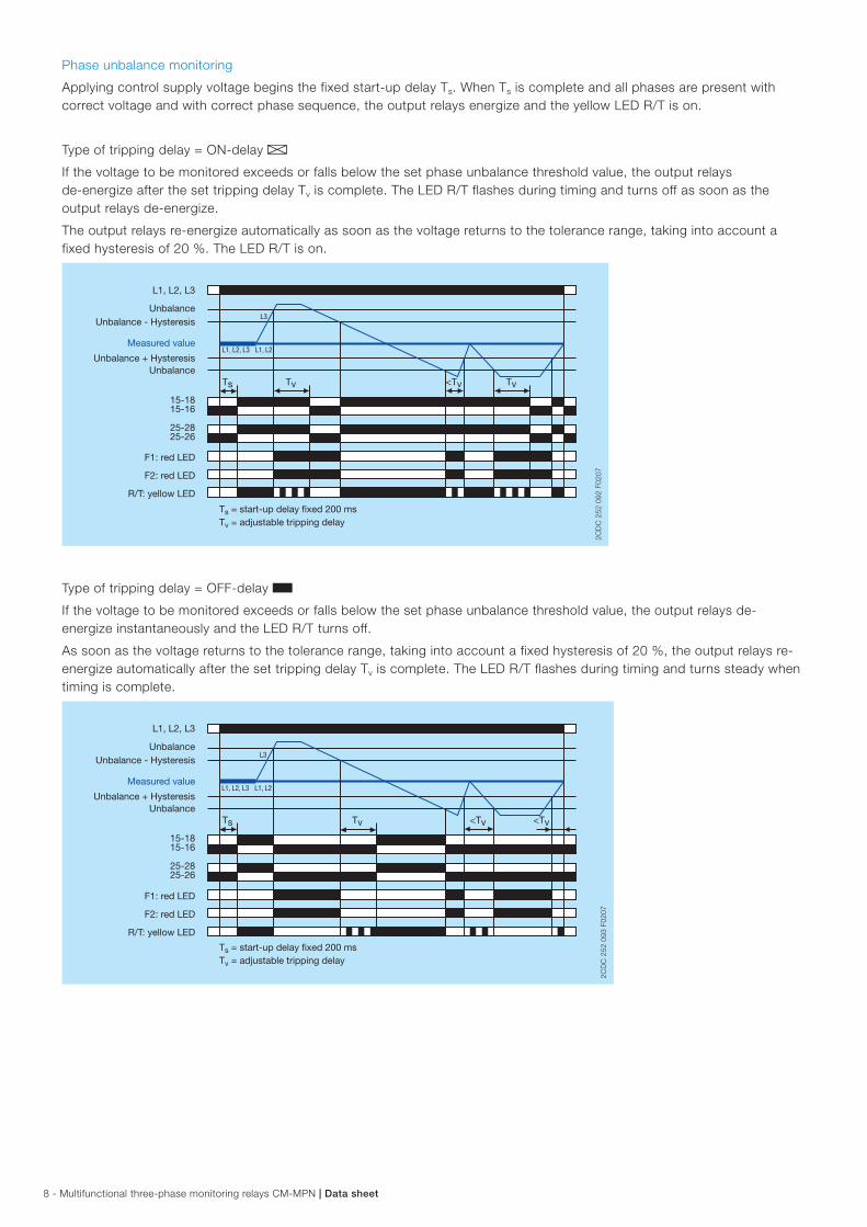
Phase unbalance monitoring
Applying control supply voltage begins the fixed start-up delay Ts. When Ts is complete and all phases are present with correct voltage and with correct phase sequence, the output relays energize and the yellow LED R/T is on.
Type of tripping delay = ON-delay A
If the voltage to be monitored exceeds or falls below the set phase unbalance threshold value, the output relays de-energize after the set tripping delay Tv is complete. The LED R/T flashes during timing and turns off as soon as the output relays de-energize.
The output relays re-energize automatically as soon as the voltage returns to the tolerance range, taking into account a fixed hysteresis of 20 %. The LED R/T is on.
L1, L2, L3
15-1615-18
L1, L2, L3 L1, L2
L3
Ts Tv Tv<Tv
25-2625-28
2CD
C 2
52 0
92 F
0207
F1: red LED
F2: red LED
R/T: yellow LED
Measured value
UnbalanceUnbalance - Hysteresis
Unbalance + HysteresisUnbalance
Ts = start-up delay fixed 200 msTv = adjustable tripping delay
2CD
C 2
52 0
92 F
0207
Type of tripping delay = OFF-delay B
If the voltage to be monitored exceeds or falls below the set phase unbalance threshold value, the output relays de-energize instantaneously and the LED R/T turns off.
As soon as the voltage returns to the tolerance range, taking into account a fixed hysteresis of 20 %, the output relays re-energize automatically after the set tripping delay Tv is complete. The LED R/T flashes during timing and turns steady when timing is complete.
25-2625-28
L1, L2, L3
15-1615-18
Ts <Tv<TvTv
L1, L2, L3 L1, L2
L3
2CD
C 2
52 0
93 F
0207
F1: red LED
F2: red LED
R/T: yellow LED
Measured value
UnbalanceUnbalance - Hysteresis
Unbalance + HysteresisUnbalance
Ts = start-up delay fixed 200 msTv = adjustable tripping delay
2CD
C 2
52 0
93 F
0207
Data sheet | Multifunctional three-phase monitoring relays CM-MPN - 9
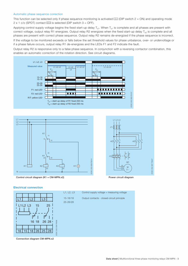
Automatic phase sequence correction
This function can be selected only if phase sequence monitoring is activated k (DIP switch 2 = ON) and operating mode 2 x 1 c/o (SPDT) contact j is selected (DIP switch 3 = OFF).
Applying control supply voltage begins the fixed start-up delay Ts1. When Ts1 is complete and all phases are present with correct voltage, output relay R1 energizes. Output relay R2 energizes when the fixed start-up delay Ts2 is complete and all phases are present with correct phase sequence. Output relay R2 remains de-energized if the phase sequence is incorrect.
If the voltage to be monitored exceeds or falls below the set threshold values for phase unbalance, over- or undervoltage or if a phase failure occurs, output relay R1 de-energizes and the LEDs F1 and F2 indicate the fault.
Output relay R2 is responsive only to a false phase sequence. In conjunction with a reversing contactor combination, this enables an automatic correction of the rotation direction. See circuit diagrams.
L1, L2, L3
15-1615-18
Ts2
Ts1 Ts1
L1, L2, L3L1, L2, L3 L1, L3, L2L1, L2
L3
25-2625-28
Ts2
F1: red LED
F2: red LED
R/T: yellow LED
Measured value
Ts1 = start-up delay of R1 fixed 250 msTs2 = start-up delay of R2 fixed 200 ms
2CD
C 2
52 0
85 F
0107
K1
K1
K1
K3 H1
L1L2L3
N
16
28
A1
25
26
15
18
K2A2
A1
A2
2CD
C 2
53 0
09 F
0014
-K3
L1
-F11
2
95
96
97
98
L2
3
4
L3
5
6
1
2
3
4
5
6-K2
-F2
1
2
3
4
5
6
1
3
5
2
4
6
M3 ~
W1V1U1
-M1
2CD
C 2
52 0
87 F
0b07
Control circuit diagram (K1 = CM-MPN.x2) Power circuit diagram
Electrical connection
L1 L2
282615 25
L3
L3 15
16 18 26 28
25L2L1
16 18
2CD
C 2
52 0
38 F
0008
L1, L2, L3 Control supply voltage = measuring voltage
15-16/18
25-26/28
Output contacts - closed-circuit principle
Connection diagram CM-MPN.x2
10 - Multifunctional three-phase monitoring relays CM-MPN | Data sheet
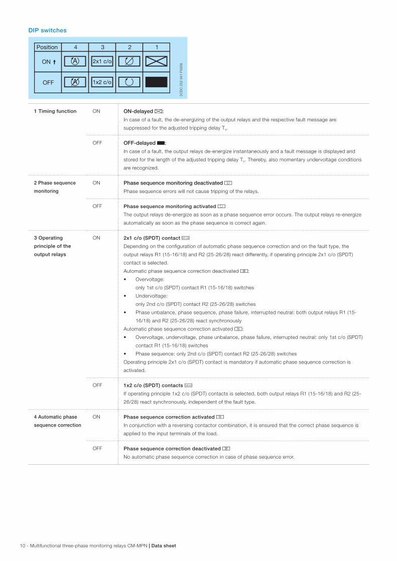
DIP switches
Position 4 1 2 3
ON
OFF
2CD
C 2
52 0
41 F
0008
1 Timing function ON ON-delayed A:
In case of a fault, the de-energizing of the output relays and the respective fault message are
suppressed for the adjusted tripping delay Tv.
OFF OFF-delayed B:
In case of a fault, the output relays de-energize instantaneously and a fault message is displayed and
stored for the length of the adjusted tripping delay Tv. Thereby, also momentary undervoltage conditions
are recognized.
2 Phase sequence
monitoring
ON Phase sequence monitoring deactivated l
Phase sequence errors will not cause tripping of the relays.
OFF Phase sequence monitoring activated k
The output relays de- energize as soon as a phase sequence error occurs. The output relays re- energize
automatically as soon as the phase sequence is correct again.
3 Operating
principle of the
output relays
ON 2x1 c/o (SPDT) contact i
Depending on the configuration of automatic phase sequence correction and on the fault type, the
output relays R1 (15-16/18) and R2 (25-26/28) react differently, if operating principle 2x1 c/o (SPDT)
contact is selected.
Automatic phase sequence correction deactivated n:
• Overvoltage:
only 1st c/o (SPDT) contact R1 (15-16/18) switches
• Undervoltage:
only 2nd c/o (SPDT) contact R2 (25-26/28) switches
• Phase unbalance, phase sequence, phase failure, interrupted neutral: both output relays R1 (15-
16/18) and R2 (25-26/28) react synchronously
Automatic phase sequence correction activated m:
• Overvoltage, undervoltage, phase unbalance, phase failure, interrupted neutral: only 1st c/o (SPDT)
contact R1 (15-16/18) switches
• Phase sequence: only 2nd c/o (SPDT) contact R2 (25-26/28) switches
Operating principle 2x1 c/o (SPDT) contact is mandatory if automatic phase sequence correction is
activated.
OFF 1x2 c/o (SPDT) contacts j
If operating principle 1x2 c/o (SPDT) contacts is selected, both output relays R1 (15-16/18) and R2 (25-
26/28) react synchronously, independent of the fault type.
4 Automatic phase
sequence correction
ON Phase sequence correction activated m
In conjunction with a reversing contactor combination, it is ensured that the correct phase sequence is
applied to the input terminals of the load.
OFF Phase sequence correction deactivated n
No automatic phase sequence correction in case of phase sequence error.
Data sheet | Multifunctional three-phase monitoring relays CM-MPN - 11
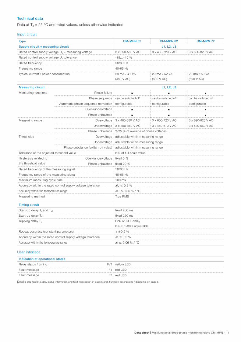
Technical data
Data at Ta = 25 °C and rated values, unless otherwise indicated
Input circuit
Type CM-MPN.52 CM-MPN.62 CM-MPN.72
Supply circuit = measuring circuit L1, L2, L3
Rated control supply voltage Us = measuring voltage 3 x 350-580 V AC 3 x 450-720 V AC 3 x 530-820 V AC
Rated control supply voltage Us tolerance -15...+10 %
Rated frequency 50/60 Hz
Frequency range 45-65 Hz
Typical current / power consumption 29 mA / 41 VA
(480 V AC)
29 mA / 52 VA
(600 V AC)
29 mA / 59 VA
(690 V AC)
Measuring circuit L1, L2, L3
Monitoring functions Phase failure J J J
Phase sequence can be switched off can be switched off can be switched off
Automatic phase sequence correction configurable configurable configurable
Over-/undervoltage J J J
Phase unbalance J J J
Measuring range Overvoltage 3 x 480-580 V AC 3 x 600-720 V AC 3 x 690-820 V AC
Undervoltage 3 x 350-460 V AC 3 x 450-570 V AC 3 x 530-660 V AC
Phase unbalance 2-25 % of average of phase voltages
Thresholds Overvoltage adjustable within measuring range
Undervoltage adjustable within measuring range
Phase unbalance (switch-off value) adjustable within measuring range
Tolerance of the adjusted threshold value 6 % of full-scale value
Hysteresis related to
the threshold value
Over-/undervoltage fixed 5 %
Phase unbalance fixed 20 %
Rated frequency of the measuring signal 50/60 Hz
Frequency range of the measuring signal 45-65 Hz
Maximum measuring cycle time 100 ms
Accuracy within the rated control supply voltage tolerance DU 0.5 %
Accuracy within the temperature range DU 0.06 % / °C
Measuring method True RMS
Timing circuit
Start-up delay Ts and Ts2 fixed 200 ms
Start-up delay Ts1 fixed 250 ms
Tripping delay Tv ON- or OFF-delay
0 s; 0.1-30 s adjustable
Repeat accuracy (constant parameters) < w0.2 %
Accuracy within the rated control supply voltage tolerance Dt 0.5 %
Accuracy within the temperature range Dt 0.06 % / °C
User interface
Indication of operational states
Relay status / timing R/T yellow LED
Fault message F1 red LED
Fault message F2 red LED
Details see table ‚LEDs, status information and fault messages‘ on page 5 and ‚Function descriptions / diagrams‘ on page 5.

12 - Multifunctional three-phase monitoring relays CM-MPN | Data sheet
Output circuits
Kind of output 15-16/18
25-26/28relays, 1 x 2 or 2 x 1 (SPDT) contact(s) configurable
Operating principle closed-circuit principle 1)
Contact material AgNi alloy, Cd free
Rated operational voltage Ue 250 V
Minimum switching voltage / Minimum switchting current 24 V / 10 mA
Maximum switchting voltage / Maximum switching current see load limit curves
Rated operational current Ie AC-12 (resistive) at 230 V 4 A
AC-15 (inductive) at 230 V 3 A
DC-12 (resistive) at 24 V 4 A
DC-13 (inductive) at 24 V 2 A
AC rating (UL 508) Utilization category
(Control Circuit Rating Code)B 300
max. rated operational voltage 300 V AC
max. continuous thermal current at B 300 5 A
max. making/breaking apparent power
at B 3003600/360 VA
Mechanical lifetime 30 x 106 switching cycles
Electrical lifetime AC-12, 230 V, 4 A 0.1 x 10⁶ switching cycles
Maximum fuse rating to achieve
short-circuit protection
n/c contact 10 A fast-acting
n/o contact 10 A fast-acting
General data
MTBF on request
Duty time 100 %
Dimensions see ‘Dimensional drawings’
Weight Screw connection technology Easy Connect Technology (push-in)
net weight CM-MPN.52 0.230 kg (0.507 lb) 0.226 kg (0.498 lb)
CM-MPN.62 0.229 kg (0.504 lb) 0.224 kg (0.494 lb)
CM-MPN.72 0.224 kg (0.494 lb) 0.220 kg (0.485 lb)
gross weight CM-MPN.52 0.255 kg (0.562 lb) 0.251 kg (0.553 lb)
CM-MPN.62 0.254 kg (0.560 lb) 0.250 kg (0.551 lb)
CM-MPN.72 0.249 kg (0.549 lb) 0.245 kg (0.540 lb)
Mounting DIN rail (IEC/EN 60715), snap-on mounting without any tool
Mounting position any
Minimum distance to other units not necessary
Material of housing UL 94 V-0
Degree of protection housing IP50
terminals IP20
1) Closed-circuit principle: Output relay(s) de-energize(s) if measured value exceeds or falls below the adjusted threshold value.
Data sheet | Multifunctional three-phase monitoring relays CM-MPN - 13
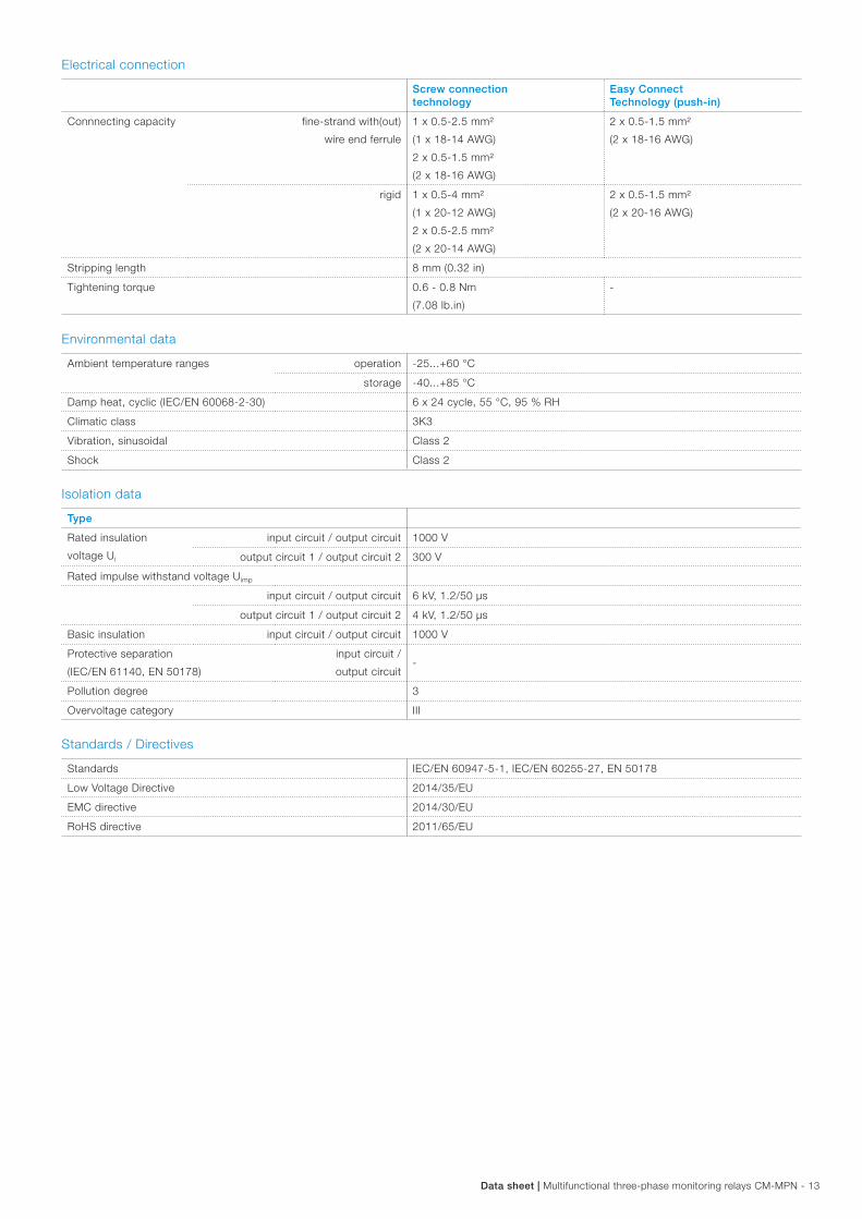
Electrical connection
Screw connection technology
Easy Connect Technology (push-in)
Connnecting capacity fine-strand with(out)
wire end ferrule
1 x 0.5-2.5 mm²
(1 x 18-14 AWG)
2 x 0.5-1.5 mm²
(2 x 18-16 AWG)
2 x 0.5-1.5 mm²
(2 x 18-16 AWG)
rigid 1 x 0.5-4 mm²
(1 x 20-12 AWG)
2 x 0.5-2.5 mm²
(2 x 20-14 AWG)
2 x 0.5-1.5 mm²
(2 x 20-16 AWG)
Stripping length 8 mm (0.32 in)
Tightening torque 0.6 - 0.8 Nm
(7.08 lb.in)
-
Environmental data
Ambient temperature ranges operation -25...+60 °C
storage -40...+85 °C
Damp heat, cyclic (IEC/EN 60068-2-30) 6 x 24 cycle, 55 °C, 95 % RH
Climatic class 3K3
Vibration, sinusoidal Class 2
Shock Class 2
Isolation data
Type
Rated insulation
voltage Ui
input circuit / output circuit 1000 V
output circuit 1 / output circuit 2 300 V
Rated impulse withstand voltage Uimp
input circuit / output circuit 6 kV, 1.2/50 µs
output circuit 1 / output circuit 2 4 kV, 1.2/50 µs
Basic insulation input circuit / output circuit 1000 V
Protective separation
(IEC/EN 61140, EN 50178)
input circuit /
output circuit-
Pollution degree 3
Overvoltage category III
Standards / Directives
Standards IEC/EN 60947-5-1, IEC/EN 60255-27, EN 50178
Low Voltage Directive 2014/35/EU
EMC directive 2014/30/EU
RoHS directive 2011/65/EU
14 - Multifunctional three-phase monitoring relays CM-MPN | Data sheet
Electromagnetic compatibility
Type
Interference immunity to IEC/EN 61000-6-2
electrostatic discharge IEC/EN 61000-4-2 Level 3 (6 kV / 8 kV)
radiated, radio-frequency,
electromagnetic field
IEC/EN 61000-4-3 Level 3 (10 V/m)
electrical fast transient / burst IEC/EN 61000-4-4 Level 3 (2 kV / 2 kHz)
surge IEC/EN 61000-4-5 Level 4 (2 kV L-L)
conducted disturbances, induced by
radio-frequency fields
IEC/EN 61000-4-6 Level 3 (10 V)
harmonics and interharmonics IEC/EN 61000-4-13 Class 3
Interference emission IEC/EN 61000-6-3
high-frequency radiated IEC/CISPR 22,
EN 55022
Class B
high-frequency conducted IEC/CISPR 22,
EN 55022
Class B
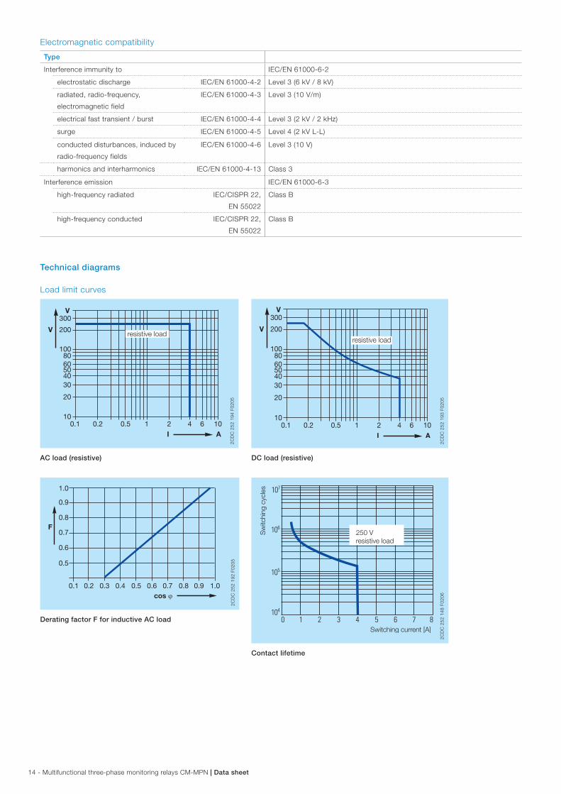
Technical diagrams
Load limit curves
300
200
1008060504030
20
101 2 4 6 10
I A
V
V
0.1 0.2 0.5
resistive load
2CD
C 2
52 1
94 F
0205
AC load (resistive)
300
200
100 80 60 50 40 30
20
10 1 2 4 6 10
I A
V
V
0.1 0.2 0.5
resistive load
2CD
C 2
52 1
93 F
0205
DC load (resistive)
cos ϕ
F
0.5
0.1 0.2 0.3 0.4 0.5 0.6 0.7 0.8 0.9 1.0
0.6
0.7
0.8
0.9
1.0
2CD
C 2
52 1
92 F
0205
Derating factor F for inductive AC load
Switching current [A]
Sw
itchi
ng c
ycle
s
250 Vresistive load
2CD
C 2
52 1
48 F
0206
Contact lifetime
Data sheet | Multifunctional three-phase monitoring relays CM-MPN - 15
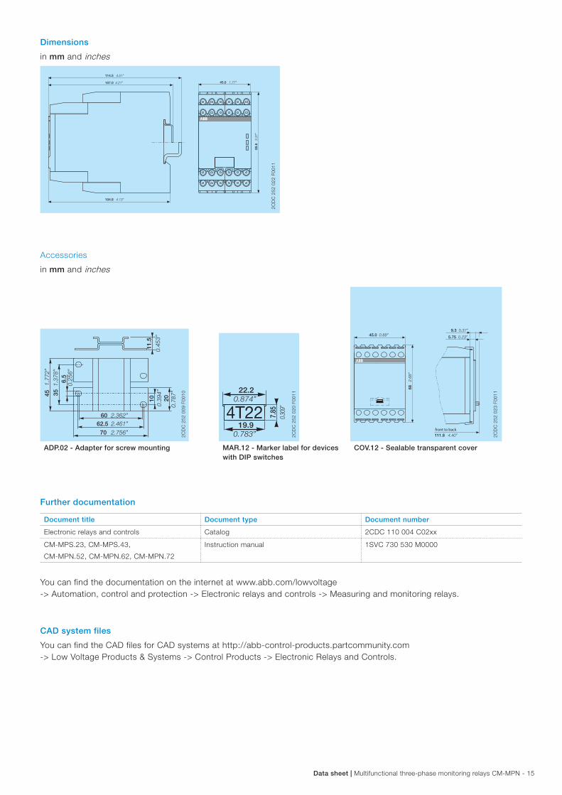
Dimensions
in mm and inches
114.5 4.51”
45.0 1.77”
85.6
3.37
”
104.8 4.13”
107.0 4.21”
2CD
C 2
52 0
22 F
0011
Accessories
in mm and inches
45.0 0.89”
68 2.68
”
111.8 4.40”
9.3 0.37”
5.75 0.23”
front to back
2CD
C 2
52 0
23 F
0011
6.5
62.560
1011
.5
20
0.25
6”
351.37
8”
451.77
2”
2.461”
70 2.756”
2.362”
0.39
4”
0.78
7”
0.45
3”
2CD
C 2
52 0
09 F
0010
19.94T22 7.
850.30
9”
0.783”
22.20.874”
2CD
C 2
52 0
20 F
0011
ADP.02 - Adapter for screw mounting MAR.12 - Marker label for devices with DIP switches
COV.12 - Sealable transparent cover
Further documentation
Document title Document type Document number
Electronic relays and controls Catalog 2CDC 110 004 C02xx
CM-MPS.23, CM-MPS.43,
CM-MPN.52, CM-MPN.62, CM-MPN.72
Instruction manual 1SVC 730 530 M0000
You can find the documentation on the internet at www.abb.com/lowvoltage -> Automation, control and protection -> Electronic relays and controls -> Measuring and monitoring relays.
CAD system files
You can find the CAD files for CAD systems at http://abb-control-products.partcommunity.com -> Low Voltage Products & Systems -> Control Products -> Electronic Relays and Controls.
ABB STOTZ-KONTAKT GmbHP. O. Box 10 16 8069006 Heidelberg, GermanyPhone: +49 (0) 6221 7 01-0Fax: +49 (0) 6221 7 01-13 25E-mail: [email protected]
You can find the address of your local sales organisation on the ABB home pagehttp://www.abb.com/contacts -> Low Voltage Products and Systems
Contact us
Note:We reserve the right to make technical changes or modify the contents of this document without prior notice. With regard to purchase orders, the agreed particulars shall prevail. ABB AG does not accept any responsibility whatsoever for potential errors or possible lack of information in this document.
We reserve all rights in this document and in the subject matter and illustrations contained therein. Any reproduction, disclosure to third parties or utilization of its contents – in whole or in parts – is forbidden without prior written consent of ABB AG.
Copyright© 2017 ABB All rights reserved
Do
cum
ent
num
ber
2C
DC
112
177
D02
01 (0
3.20
17)