Embed Size (px)
Citation preview

Multiframe
Windows Version 10
Automation Manual
© Formation Design Systems Pty Ltd 1984 – 2007


iii
License & Copyright Multiframe Program © 1985-2007 Formation Design Systems Multiframe is copyrighted and all rights are reserved. The license for use is granted to the purchaser by Formation Design Systems. As a single user license and does not permit the program to be used on more than one machine at one time. Copying of the program to other media is permitted for back-up purposes as long as all copies remain in the possession of the purchaser. Multiframe User Manual © 1985-2007 Formation Design Systems All rights reserved. No part of this publication may be reproduced, transmitted, transcribed, stored in a retrieval system, or translated into any language in any form or by any means, without the written permission of Formation Design Systems. Formation Design Systems, reserve the right to revise this publication from time to time and to make changes to the contents without obligation to notify any person or organization of such changes. DISCLAIMER OF WARRANTY Neither Formation Design Systems, nor the author of this program and documentation are liable or responsible to the purchaser or user for loss or damage caused, or alleged to be caused, directly or indirectly by the software and its attendant documentation, including (but not limited to) interruption on service, loss of business, or anticipatory profits. No Formation Design Systems distributor, or agent, or employee is authorized to make any modification, extension, or addition to this warranty.

v
Table of Contents License & Copyright .........................................................................................................iii Table of Contents ............................................................................................................... v About this Manual .............................................................................................................. 7 Chapter 1 Introduction........................................................................................................ 9
Automation ....................................................................................................9 VBA...............................................................................................................9 Object Models..............................................................................................10 Uses of Automation .....................................................................................10 What can’t I automate? ................................................................................10 Terminology.................................................................................................11 Speed............................................................................................................11 Code Samples ..............................................................................................11 Early and Late Binding ................................................................................12 Object Browser ............................................................................................13 Further Reading ...........................................................................................13
Chapter 2 The Multiframe Object Model ......................................................................... 15 Collections, Objects and Lists......................................................................15 Application Object .......................................................................................17 Preferences Object .......................................................................................17 Sections Library Object ...............................................................................17 Frame Object................................................................................................18 Nodes and Elements.....................................................................................19 Members ......................................................................................................19 Springs, Restraints and NodeMasses ...........................................................19 NodeLinkGroups .........................................................................................20 LoadCases and the Loading objects.............................................................20 GroupSets and Groups .................................................................................20 ProjectInfo ...................................................................................................21 The Analysis Objects ...................................................................................21 Results Hierarchy.........................................................................................21 Indices, Numbers and ID’s ..........................................................................22 Common Properties and Methods................................................................22 Arrays ..........................................................................................................24 Variant Parameters in Methods....................................................................24
Chapter 3 Getting Started ................................................................................................. 27 A Simple Macro...........................................................................................27 A Basic Multiframe Script ...........................................................................27 Creating a Portal Frame ...............................................................................28 Applying Loads............................................................................................31 Running an Analysis ....................................................................................32 Units.............................................................................................................33 The Final Script ...........................................................................................33
Chapter 4 Modelling the Frame........................................................................................ 35 Frame Object................................................................................................35 Nodes ...........................................................................................................38 Elements.......................................................................................................43 Restraints .....................................................................................................53 Springs .........................................................................................................55 Node Linking ...............................................................................................57 Node Masses ................................................................................................60

vi
GroupSets.....................................................................................................63 Groups..........................................................................................................64 Members ......................................................................................................67 Project Details..............................................................................................71 Improving performance with lists ................................................................72
Chapter 5 The Load Objects............................................................................................. 75 Load Cases...................................................................................................75 Node Loads ..................................................................................................78 Prescribed Displacements ............................................................................80 Element loads...............................................................................................81 Thermal Loads .............................................................................................85 Deleting Loads.............................................................................................87 Expression Parsing and Variants .................................................................88
Chapter 6 Automating Analysis ....................................................................................... 89 Linear Static Analysis ..................................................................................90 Non-linear Static Analysis ...........................................................................90 Modal Analysis ............................................................................................92 Time History Analysis .................................................................................93
Chapter 7 Results Objects ................................................................................................ 95 The Results Object.......................................................................................95 Result Cases.................................................................................................96 Linear and Non-linear Results .....................................................................97 Modal Results ..............................................................................................98 Nodal Results ...............................................................................................99 Element Results .........................................................................................101 Member Results .........................................................................................107
Chapter 8 Sections Library............................................................................................. 109 SectionsLibrary Object ..............................................................................109 SectionGroup Object..................................................................................111 Sections Object ..........................................................................................113
Chapter 9 Preferences and Units .................................................................................... 119 Sign Conventions.......................................................................................119 Units...........................................................................................................119
Chapter 10 Collections and Lists.................................................................................... 121 Collections .................................................................................................121 Lists............................................................................................................122 The Find Method .......................................................................................126
Chapter 11 User Interface............................................................................................... 127 Selection Object .........................................................................................127
Chapter 12 Examples...................................................................................................... 131 Reproducing Multiframes Data Window in Excel.....................................131 Reproducing Multiframes Result Window in Excel ..................................137 Customised Reporting using Word............................................................137
Appendix A Object Model Summary............................................................................. 141 Objects .......................................................................................................141 Enumerated Types .....................................................................................142
Index............................................................................................................................... 147

About this manual
Page 7
About this Manual This manual describes the Multiframe automation interface which lets you write macros, scripts and programs to access data from Multiframe or to create and analyse models in Multiframe. The manual provides a description of the objects, properties and methods contained in the Multiframe Automation Interface. VBA code examples have been used throughout the manual to demonstrate how best to use these objects. Chapter 1 Introduction; This chapter provides an introduction to automation and many of the general concepts needed to get started using VBA. It describes what can and can’t be automated and provides a list of other resources that you may find useful in writing your own macros and scripts. Chapter 2 The Multiframe Object Model; Presents an overview of the Multiframe Object model by describing each of the objects used within the model. Chapter 3 Getting Started; Gets you started writing a simple script to automate Multiframe. It is a simple series of exercises designed to introduce you to many of the objects within the Multiframe object model. Chapter 4 Modelling the Frame; Presents a detailed description of the objects used in modelling the structure. This includes objects describing joints, elements, restraints, joint linking and design members. Chapter 5 The Load Objects; In this chapter the objects used for loading a structure are discussed. Objects used for describing load cases and each of the individual loads are all described in detail. Chapter 6 Automating Analysis; This chapter describes the objects used to control and execute and analysis. Chapter 7 Results Objects; The results of analyses are available via the Multiframe Object model and are accessed via a hierarchy of objects that are described in this chapter. Chapter 8 Sections Library; Describes the objects that represent sections, groups and the sections library. Chapter 9 Preferences and Units; Provides a description of the objects that control the settings and units used within Multiframe. Chapter 10 Collections and Lists; This chapter outlines the use of collections and lists to manage groups of objects. Chapter 11 User Interface; This chapter describes which items in the Multiframe user interface can be controlled using Automation. Chapter 12 Examples; A number of examples are presented that demonstrate using Microsoft Word and Excel to control the Multiframe Automation Interface.


Chapter 1 Introduction
Page 9
Chapter 1 Introduction This chapter provides an introduction to automation, VBA and object models and their use in writing macros for Multiframe. It discusses the applications that can be used to access and control Multiframe and presents examples on how this can be done.
Automation Automation is a term used to describe the ability of one application to control or access data from another. Automation is a common feature in many Microsoft applications such as Word and Excel. In fact, the macros in each of these applications are written using automation. The automation interface in these applications gives a user access to a range of objects that can be used to control the application and its data. For example, Microsoft Word contains paragraph, word and font objects. In a similar way, Multiframe’s automation interface contains node, element and load objects amongst others. Multiframe provides support for automation via an interface that allows the user to create a frame, perform an analysis and examine the results. While the Multiframe application does not incorporate a facility for directly writing or recording macros, the automation interface will allow users to develop macros for Multiframe in other applications. Multiframe’s automation interface enables it to interact with many other applications that support automation. This is very easily achieved in applications that provide a suitable VBA macro-programming environment such as
• Microsoft Excel
• Microsoft Word
• Microsoft Access
• AutoCAD 2000
• MathCAD Automation can also be used via many modern programming languages such as Visual Basic, Visual C++, Java and even Compaq Visual Fortran. It is even supported by the Windows Scripting Host, which can be used to automate applications directly from the Windows environment.
For the technically inclined… The core technology behind Multiframe is COM, Microsoft’s Common Object Model. If you are familiar with COM you can use Multiframe’s COM interface as you would the COM interface of any other program. It can be accessed using VB, C++, C, Java or any other COM compatible language.
VBA Visual Basic for Applications, or simply VBA, is Microsoft’s application scripting language. It is the language used to write macros within the entire Microsoft Office suite and in other Microsoft products. It is also used within applications written by other vendors such as AutoCAD and MathCAD. If you have experience in writing macros within any of these products then you should be able to quickly adapt to writing macros for Multiframe.

Chapter 1 Introduction
Page 10
VBA is the most readily available platform in which to write Multiframe macros as most engineers have access to Microsoft Excel or Microsoft Word. It is also a relatively easy environment in which to develop scripts, macros or small programs that exploit automation. As such, this manual will concentrate of the use of VBA for the development of macros for Multiframe. All examples presented in the manual will be coded using VBA.
Object Models The key to the use of VBA within all these different applications is that VBA is simply a language for manipulating objects. Each application that uses VBA for scripting has its own object model that is a unique set of objects that can be manipulated by the language. If you are familiar with VBA then learning to write macros for another application only involves learning that application’s object model. By mastering the use of VBA for writing Multiframe macros you will also be able to quickly adapt to writing macros in many other products.
Uses of Automation Automation is a powerful tool that can be used to write anything from a simple macro to a full windows application. In fact this is the technology that allows Multiframe to directly generate reports in Microsoft word. Some examples of how this technology could be employed are:
• A macro to manipulate the geometry of a selection in the Frame Window, for example a mirror function.
• Generating customised reports in Microsoft Word
• Generating HTML reports using Microsoft Word
• Exporting data to a Microsoft Access database that could be used to manage fabrication or perform a costing
• Writing a VB program to import or export a structure to other file formats or programs
• Writing a script to find members with particular properties
• Writing Excel macros to automatically access design data from Multiframe
• Batch processing of analyses overnight using Windows Scripting Each of these examples could be designed as a simple macro or with a sophisticated user interface. Once familiar with VBA, it is an easy task to add dialogs and menus to your automation scripts.
What can’t I automate? The following parts of the Multiframe application and data structures can not be accessed using the current Multiframe object model. This may change in future.
Chapter 1 Introduction
Page 11
• Time History load cases and results.
• Design data and results.
• The Multiframe user interface (i.e. Windows, menus, toolbars etc.) except for selections in the individual windows.
Terminology The terminology used in the automation interface is slightly different to that used in the Multiframe user program. Each nodal point in the structure is referred to as a Joint in the program but as a Node in the automation interface. In addition, a Member in the program is called an Element in the automation interface while a Member in the automation interface is a Design Member in the program. Another significant difference in the terminology is used to describe the Master-Slave relationships. In the automation interface the Master Slave groups are referred to as Node Link groups.
Speed An important issue in automation programming is speed; automated scripts or macros can be relatively slow when they require making calls between applications. There are a number of techniques for helping to improve their performance, the most important of which is to minimize the number of calls between applications. The Multiframe automation interface has been designed to provide the advanced user with a number of techniques for minimizing the number of calls across the interface. This includes using collections and lists to add or modify a group of objects at once and the exchange of data using arrays contained within VARIANT data types. Examples of these are given in Chapter 10 Collections and Lists and in Chapter 12 Examples.
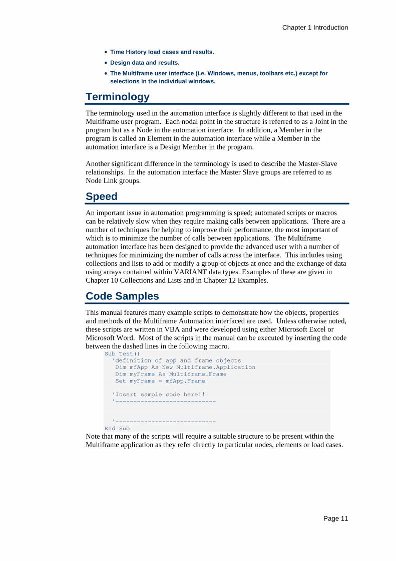
Code Samples This manual features many example scripts to demonstrate how the objects, properties and methods of the Multiframe Automation interfaced are used. Unless otherwise noted, these scripts are written in VBA and were developed using either Microsoft Excel or Microsoft Word. Most of the scripts in the manual can be executed by inserting the code between the dashed lines in the following macro.
Sub Test() 'definition of app and frame objects Dim mfApp As New Multiframe.Application Dim myFrame As Multiframe.Frame Set myFrame = mfApp.Frame 'Insert sample code here!!! '---------------------------- '---------------------------- End Sub
Note that many of the scripts will require a suitable structure to be present within the Multiframe application as they refer directly to particular nodes, elements or load cases.
Chapter 1 Introduction
Page 12
All the example code presented in this manual was written using the VBA editor provided within Microsoft Office 2000. This code uses some features not available in the version of VBA provided with earlier versions of Microsoft Office. One significant difference is that the older version of VBA does not support the use of enumerated data types which have been used throughout the Multiframe Object model. For this reason we recommend the use of Microsoft Office 2000 products when writing VBA scripts. However, scripts can still be written using Office 97 in which case enumerated values must be replaced by their integer value. All the enumerated types, and their values, used by the Multiframe Automation Model are listed in Appendix A of this document.
Early and Late Binding To manipulate Multiframe using VBA scripting in another application it is necessary to first create an instance of Multiframe Application object. This can be done using either Early Binding or Late Binding. Late binding uses the CreateObject method to create an instance of the Application object. For example, to create a new instance of Multiframe using late binding:
Dim mfApp As Object Set mfApp = CreateObject("Multiframe.Application")
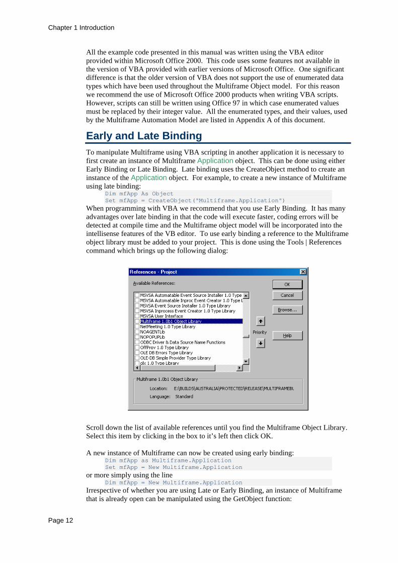
When programming with VBA we recommend that you use Early Binding. It has many advantages over late binding in that the code will execute faster, coding errors will be detected at compile time and the Multiframe object model will be incorporated into the intellisense features of the VB editor. To use early binding a reference to the Multiframe object library must be added to your project. This is done using the Tools | References command which brings up the following dialog:
Scroll down the list of available references until you find the Multiframe Object Library. Select this item by clicking in the box to it’s left then click OK. A new instance of Multiframe can now be created using early binding:
Dim mfApp as Multiframe.Application Set mfApp = New Multiframe.Application
or more simply using the line Dim mfApp = New Multiframe.Application
Irrespective of whether you are using Late or Early Binding, an instance of Multiframe that is already open can be manipulated using the GetObject function:

Chapter 1 Introduction
Page 13
Dim mfApp As Object Set mfApp = GetObject(, "Multiframe.Application")
or preferably using Dim mfApp As Multiframe.Application Set mfApp = GetObject(, "Multiframe.Application")
Object Browser Another advantage of using Early Binding is that you can use the Object Browser (View | Object Browser), shown below, to examine the names, properties and methods of the objects in the Multiframe Object library.
Further Reading This aim of this manual is to describe the Multiframe automation interface and its use. The manual does not aim to teach the reader how to program in VBA or any other language. It is assumed that the reader is familiar with Visual Basic or VBA programming or that you have access to materials on this topic. There are many books available on VBA, particularly in relation to the Microsoft Office suite of products. Some references and other resources that may be useful in helping you to learn VBA and automation are:
• “Microsoft Excel 2000 Power Programming with VBA” by John Walkenbach, IDG Books Worldwide, 1999
• A range of reference books on VBA programming with Word 2000, Excel 200 and AutoCAD 2000 is published by Wrox Press, www.wrox.com
• http://msdn.microsoft.com/office/default.asp
• www.mvps.org
• News groups microsoft.public.word.vba.beginners microsoft.public.word.vba.general microsoft.public.office.developer.vba


Chapter 2 The Multiframe Object Model
Page 15
Chapter 2 The Multiframe Object Model The Multiframe object model is a hierarchy that represents the underlying data and functions used in Multiframe. Most of the objects within the object model are used to describe the structural model or frame. Other objects represent the structure of the Sections Library and its associated groups and sections, or control the appearance of the Multiframe user interface. This chapter provides an overview of the Multiframe object model describing its structure and the purpose of each object within the model.
Collections, Objects and Lists When programming using VBA you manipulate objects that represent different aspects of an application as defined by its object model. A schematic diagram of the entire Multiframe object model is displayed in the diagram on the next page. It divides the Multiframe application and the structural model into many distinct objects. These objects may represent a single component of a model such a node, element or a load case. Other objects within the model do not represent a physical part of the model but are used to store settings or data such as the settings for a modal analysis or the results from an analysis for a particular node. Each Object contains Properties and Methods. The Properties are a number of variables which store properties of the object such as name, length, weight etc. The actual type and name of the properties are specific to each type of object. Methods are functions that you can use to manipulate the object. These might include methods to Add, Delete or modify values of the object. A special type of object is a collection which is a container storing an ordered set of objects of the same type. For example, the Elements collection in the Frame object contains all of the Elements in the frame. Collections within the Multiframe object model are named as the plural of the objects they contain. Most collections in Multiframe are initially empty. The exception is the LoadCases collection that initially contains a single object. All of the collections in Multiframe are 1-based i.e. the first item in the list has an index of 1. Some care must be taken when programming in VBA as it can use zero based collections and arrays in which the first item in the list has an index of zero.

Chapter 2 The Multiframe Object Model
Page 16
Application
Frame
Nodes (Node)
Elements (Element)
Loadcases (Loadcase)
Restraints (Restraint)
NodeMasses (NodeMass)
NodeLinkGroups (NodeLinkGroup)
Springs (Spring)
NodeLoads (NodeLoad)
NodePreDisps (NodePreDisp)
ThermalLoads (thermalLoad)
ElementLoads (ElementLoad)
Members (Member)
SectionsLibrary
SectionGroups (SectionGroup)
Sections (Section)
Materials (Material)
Results
Resultcases (ResultCase)
LinearResults
NonlinearResults
ModalResults
NodeResults
ElementResults
MemberResults
Preferences
LinearSettings
Analysis
NonlinearSettings
ModalSettings
ProjectInfo

Chapter 2 The Multiframe Object Model
Page 17
Application Object The root of the Multiframe object model is the Application object. All other objects within the object model can be accessed either directly or indirectly via this object. The application object provides direct access to three Multiframe objects as shown below. Application
Frame
SectionsLibrary
Preferences The Application object contains a number of shortcuts to objects contained within the frame. Both the load cases and results object for the current frame can be obtained directly from the application.
Preferences Object The preferences object provides access to settings within the Multiframe application that control how data is presented. This includes the sign conventions used to display forces and numerous methods for manipulating and accessing the units of measure. An important method of the Preferences object is the GetUnit function that returns a string containing the units name (e.g. mm, kN, ft) of a specified unit type. This is very useful when presenting data or requesting input from a user as the units of measure can easily be displayed. Note that all methods and properties in Multiframe automation use the current units.
Sections Library Object The section library that is currently open within the Multiframe application is available via the SectionsLibrary object. As shown in the diagram below, it contains collections of objects representing the groups, sections and materials contained in the library. These objects can be used to add, delete or modify the section property data stored within the library.
SectionsLibrary
SectionGroups (SectionGroup)
Materials (Material)
Sections (Section)
Chapter 2 The Multiframe Object Model
Page 18
This sections library object is accessed directly from the Application object using the SectionsLibrary property. The SectionsLibrary object contains a collection of SectionGroup objects. Each SectionGroup object in the collection corresponds directly to a group of sections in the sections library. It contains the properties associated with a group of sections as well as a collection of Section objects, each of which represents a section stored within the group. A useful property of the SectionGroup object is the SectionNames property. It returns a list of names of all the sections contained within the group. It can be used to construct a user form or dialog containing a list of sections from which the user may choose. This is much faster than individually accessing the name of each section within the group Each SectionGroup object contains a collection of Section objects representing each section in the group. The Section object provides an interface to the properties of section such as its name, dimensions, area, moments of area and section moduli. Rather than navigating the hierarchy of the SectionsLibrary object, a more direct method of accessing a section has been provided in the SectionsLibrary object. The GetSection function takes two parameters that identify the group and section. These parameters may be specified as either indices or names or even objects. The SectionsLibrary object also contains a collection of Material objects that provides a means for adding, deleting or editing materials in the library.
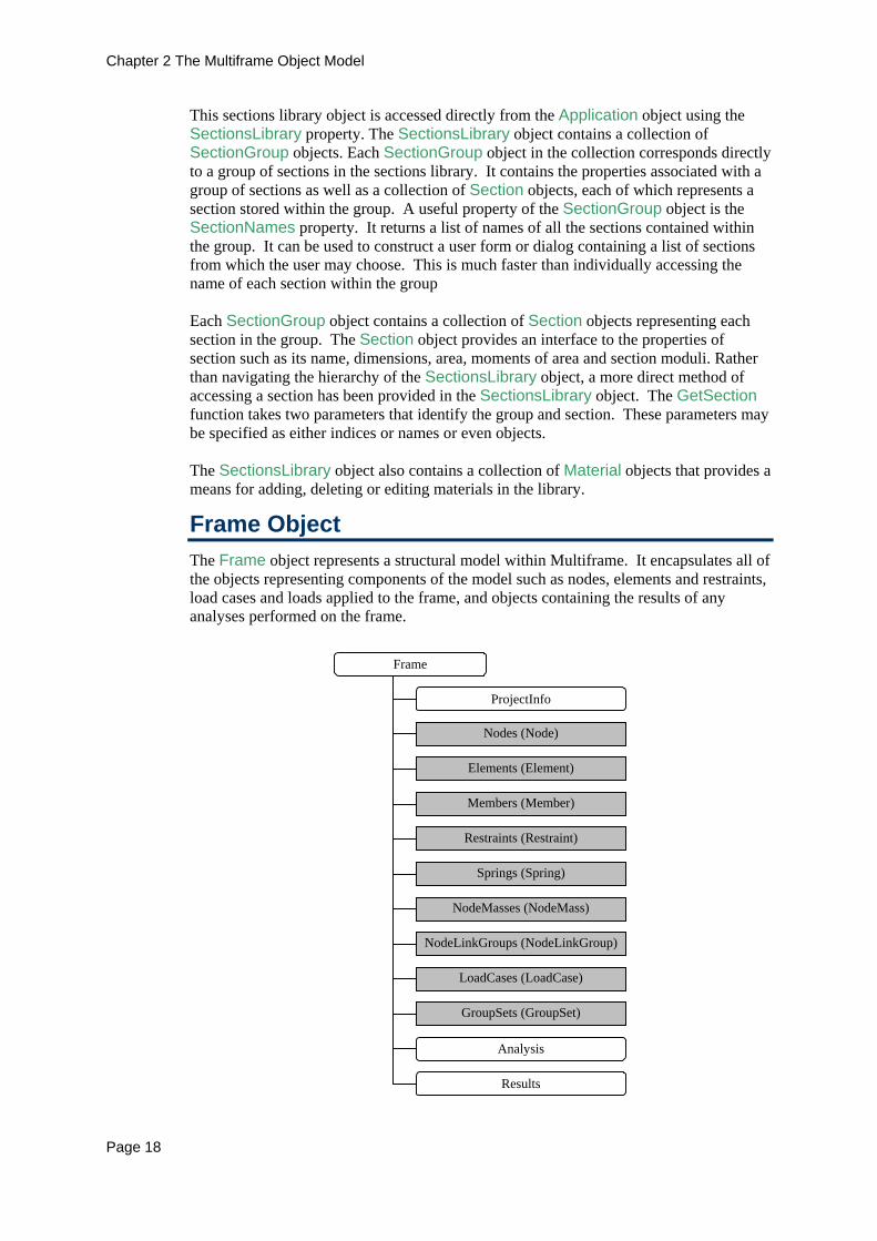
Frame Object The Frame object represents a structural model within Multiframe. It encapsulates all of the objects representing components of the model such as nodes, elements and restraints, load cases and loads applied to the frame, and objects containing the results of any analyses performed on the frame.
Frame
Nodes (Node)
Members (Member)
Elements (Element)
Restraints (Restraint)
NodeMasses (NodeMass)
Springs (Spring)
NodeLinkGroups (NodeLinkGroup)
LoadCases (LoadCase)
ProjectInfo
Analysis
Results
GroupSets (GroupSet)

Chapter 2 The Multiframe Object Model
Page 19
This object can be accessed using the Frame property of the Application object, for example:
Dim objFrame as Multiframe.Frame … Set objFrame = mfApp.Frame
The Frame object also contains the methods for Opening, Closing and Saving the frame to disk.
Nodes and Elements The geometry of a structure is defined by the position of its nodes and how they are connected by elements. The nodes and elements in a frame can be accessed via the Nodes and Elements collections of the Frame object. These collections contain Node and Element objects representing each node and element within the structure. The Node object contains the data that describes a joint in the frame. This includes its position, orientation, label and whether it is pinned or rigid. The node object also provides methods to return lists of objects associated with the node. For example, the Springs method returns a list of all springs attached to a node. The Element object provides access to data describing an individual element in a frame such as its label, section, orientation, rigid end offsets and the nodes used to define its ends. Other read only properties provide other information about the element such as its length, slope, and the coordinates of its ends. The Element object also provides functions that return lists of objects associated with an element such as all loads applied to the element. Methods are also provided with both the Node and Element objects to transform values from their local coordinate system to the global coordinate system and vice versa.
Members The Member object represents a single entity for the purpose of design. This may be a single element or a group of elements linked together to form a single design member. This object provides methods and properties for grouping or removing elements from a design member, setting the section and orientation of the member, as well as properties for describing the position, slope and length of the member.
Springs, Restraints and NodeMasses A joint restraint applied to a model is described in the Multiframe Automation interface as the Restraint object. Similarly, a joint spring and a joint mass are described within the interface using the Spring and NodeMass objects. These objects contain the properties of the different items in a frame such as the node to which the spring/restraint/mass is applied or its index within the parent collection contained by the Frame object. Each of these objects includes a Label property that may be used to identify the item or contain a string of user-defined information. This property is only available via the automation interface and cannot be edited or viewed via the user interface of the current version of Multiframe.
Chapter 2 The Multiframe Object Model
Page 20
NodeLinkGroups The Master-Slave facility in Multiframe is described in the Multiframe automation interface using node link groups. Each Master-Slave grouping is encapsulated within the NodeLinkGroup object which provides a mechanism by which to control the name of the group, nodes contained within the group, the master node and which degrees of freedom are linked by the group.
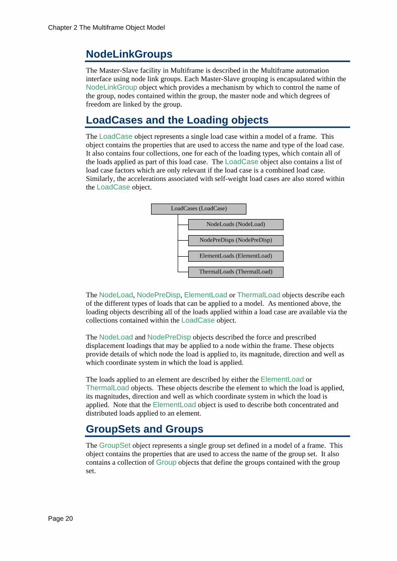
LoadCases and the Loading objects The LoadCase object represents a single load case within a model of a frame. This object contains the properties that are used to access the name and type of the load case. It also contains four collections, one for each of the loading types, which contain all of the loads applied as part of this load case. The LoadCase object also contains a list of load case factors which are only relevant if the load case is a combined load case. Similarly, the accelerations associated with self-weight load cases are also stored within the LoadCase object.
LoadCases (LoadCase)
NodeLoads (NodeLoad)
ElementLoads (ElementLoad)
NodePreDisps (NodePreDisp)
ThermalLoads (ThermalLoad)
The NodeLoad, NodePreDisp, ElementLoad or ThermalLoad objects describe each of the different types of loads that can be applied to a model. As mentioned above, the loading objects describing all of the loads applied within a load case are available via the collections contained within the LoadCase object. The NodeLoad and NodePreDisp objects described the force and prescribed displacement loadings that may be applied to a node within the frame. These objects provide details of which node the load is applied to, its magnitude, direction and well as which coordinate system in which the load is applied. The loads applied to an element are described by either the ElementLoad or ThermalLoad objects. These objects describe the element to which the load is applied, its magnitudes, direction and well as which coordinate system in which the load is applied. Note that the ElementLoad object is used to describe both concentrated and distributed loads applied to an element.
GroupSets and Groups The GroupSet object represents a single group set defined in a model of a frame. This object contains the properties that are used to access the name of the group set. It also contains a collection of Group objects that define the groups contained with the group set.

Chapter 2 The Multiframe Object Model
Page 21
GroupSets (GroupSet)
Groups (Group)
The Group object represents a single group contained within a group set. This object has properties to access the name and colour associated with the group as well as the lists of the elements and nodes that define the group.
ProjectInfo The ProjectInfo object contains properties for accessing details of the project and designer such as the project title, project description, job ID, designers name, a version number and the date the frame was last modified. This is the same data set by the Properties dialog in Multiframe’s File menu.
The Analysis Objects The analysis features of Multiframe are available via the Analysis object. This object contains the flags indicating which analyses are to be performed, the settings for each of the analyses and of course a method to perform the actual analysis.
Analysis
LinearSettings
NonlinearSettings
ModalSettings
The settings associated with each type of analysis that Multiframe can perform are contained in separate objects. The LinearSettings object contains the setting required by the linear analysis. However, this object has only been provided for consistency at there are no setting required by the linear analysis at this stage. All the settings associated with a nonlinear analysis are stored within the NonlinearSettings object, while the parameters required to perform a modal or time history analysis are specified using the ModalSettings and TimeHistorySettings objects. Note that while a time history analysis can be performed via the automation interface, the time history loading and results of time history analyses are not yet available.
Results Hierarchy The results of analyses are stored in a hierarchy with the Results object at the top. As shown below, this hierarchy divides the results from each type of analysis into separate objects. The results from the linear analysis are contained within the LinearResults object that in turn contains a collection of ResultCase objects, each of which corresponds to the results for a particular load case. Each ResultCase object contains a collection of NodeResult, ElementResult and MemberResult objects that provide an interface to the results for each node, element or member in the frame. Similarly, the results of nonlinear analyses are interfaced via the NonlinearResults object which also contains a collection of ResultCases which correspond to each load case applied to the frame. Note that each ResultCase exists irrespective of whether the case has been analysed or not. If a case has been analysed then the Solved property of the ResultCase object returns a value of true.

Chapter 2 The Multiframe Object Model
Page 22
Results
ResultCases (ResultCase)
NodeResults (NodeResult)
LinearResults
NonlinearResults
ElementResults(ElementResult)
MemberResults(MemberResult)
ModalResults
The results of a modal analysis are accessible via the ModalResults object. It contains a collection of ResultCase objects representing each mode shape in the solution. The ModalResults object also provides access to period and frequency of each mode shape. No interface is currently available for the results from time history analyses. The results for each node, element and member may be obtained directly by navigating the hierarchy described above. An alternative technique is to use the GetResults method of the respective Node, Element and Member objects.
Indices, Numbers and ID’s Any object within the Multiframe automation model that is stored within a collection will have an Index and a Number property. The index of the object represents the position of the object in its parent collection. As the collections are ordered in the same way items are numbered within Multiframe, the index is in fact the same as the number of the object in the Multiframe user interface. If items are deleted from a frame, the index of an object will always be updated accordingly. The Number property of an object currently returns the number of the object as used within Multiframes user interface. As this is the same as the items index, the Number and Index property return the same value. Future versions of Multiframe may allow the user to define the number of an item in which case the number need not be unique or part of a continuous numbering scheme. For this reason it is suggest that the Number properties is used when generating output such as reports.
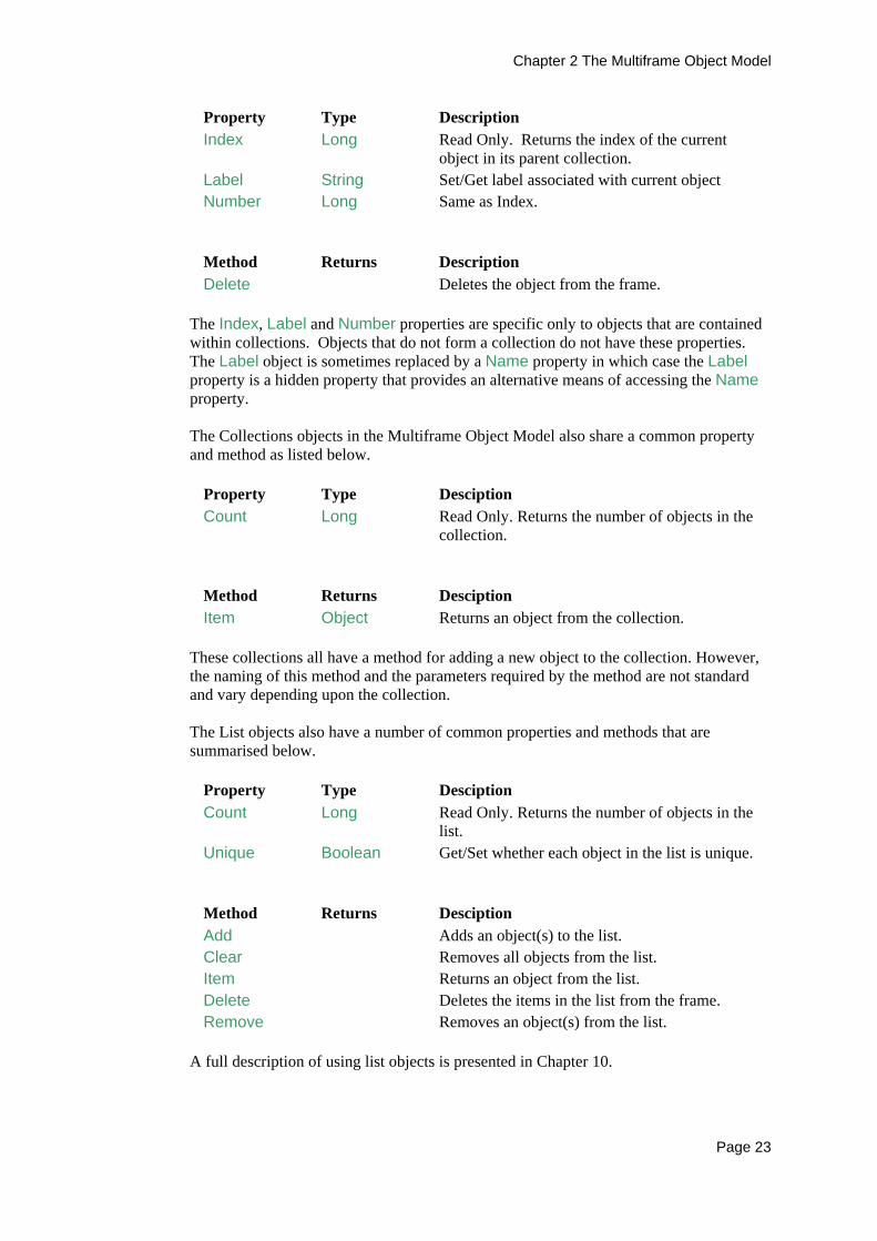
Common Properties and Methods A number of properties and methods of objects within the Multiframe Object Model are common to many of the objects within the library. To avoid unnecessary repetition within the manual, these common properties and methods are described below. All of the objects that are used to model a structure, including the loading, share a number of common properties and methods. These are summarized in the following tables.
Property Type Description Application Application Read Only. Returns a reference to the parent
application of the current object. Frame Frame Read Only. Returns a reference to the Frame
containing the current object.
Chapter 2 The Multiframe Object Model
Page 23
Property Type Description Index Long Read Only. Returns the index of the current
object in its parent collection. Label String Set/Get label associated with current object Number Long Same as Index.
Method Returns Description Delete Deletes the object from the frame.
The Index, Label and Number properties are specific only to objects that are contained within collections. Objects that do not form a collection do not have these properties. The Label object is sometimes replaced by a Name property in which case the Label property is a hidden property that provides an alternative means of accessing the Name property. The Collections objects in the Multiframe Object Model also share a common property and method as listed below.
Property Type Desciption Count Long Read Only. Returns the number of objects in the
collection.
Method Returns Desciption Item Object Returns an object from the collection.
These collections all have a method for adding a new object to the collection. However, the naming of this method and the parameters required by the method are not standard and vary depending upon the collection. The List objects also have a number of common properties and methods that are summarised below.
Property Type Desciption Count Long Read Only. Returns the number of objects in the
list. Unique Boolean Get/Set whether each object in the list is unique.
Method Returns Desciption Add Adds an object(s) to the list. Clear Removes all objects from the list. Item Returns an object from the list. Delete Deletes the items in the list from the frame. Remove Removes an object(s) from the list.
A full description of using list objects is presented in Chapter 10.
Chapter 2 The Multiframe Object Model
Page 24
Arrays All arrays used within the Multiframe automation interface are passed across the interface as variants. This provides a lot of flexibility when passing an array to a method or property as the array may be declared as either an array or a variant. However, when an array of values is returned from a property or method of an object it is returned as a variant. This means that the variable receiving the results must be declared as a variant.
Variant Parameters in Methods Many methods in the Multiframe automation interface have parameters that are of variant data type. In many cases these parameters are often used to pass arrays of values such as an array of six boolean values representing the restrained degrees of freedom at a node. In other cases they allow an object or a list of objects to be identified in many different ways. A variant parameter identifying a single object will accept the integer index of the item or the actual object. A common example is a variant parameter representing a node. This parameter will accept an integer value of the nodes index or a Node object. For example, the first parameter of the AddSpring method is a variant specifying the node to which the spring is attached. This could be coded as
Dim mySpring as Multiframe.Spring … ’Add spring to node 5 (by Index) Set mySpring = myFrame.Spring.AddSpring(5,mfDOFx,12.5)
or Dim mySpring as Multiframe.Spring Dim myNode as Multiframe.Node … ’Add spring to node 5 (by Object) Set myNode = myFrame.Nodes(5) Set mySpring = myFrame.Spring.AddSpring(myNode,mfDOFx,12.5)
A variant parameter representing a list of items will accept many different data types that identify the list of objects. This may be a single integer index, an object, a list object or even a collection of objects. A string containing a comma-delimited list of indices is also valid and may include ranges specified with a dash (e.g. “1,2,5-7”). For example, when a list of nodes is to be passed to a method, the variant parameter will accept a single integer index, a Node object, a NodeList object, a Nodes collections, an array of integer values of the nodes indices, or a string with a comma delimited list of nodes. For example, the Loads method of the Nodes object returns all the nodal force loads applied to the node. The Loads method has a single variant parameter specifying which load cases are to be considered. The following code demonstrates the many different parameters that may be passed to this function.

Chapter 2 The Multiframe Object Model
Page 25
Dim myLoads as Multiframe.NodeLoadList Dim myLCs as New Multiframe.LoadCaseList … ’Get all node loads on node 3 applied in the first load case Set myLoads = myFrame.Nodes(3).Loads(1) ’Get all node loads on node 3 applied in the third load case Set myLoads = myFrame.Nodes(3).Loads(myFrame.LoadCases(3)) ’Get all node loads on node 3 in load cases 5 and 6 (using array) Set myLoads = myFrame.Nodes(3).Loads(Array(5,6)) ’Get all node loads on node 3 in load cases 5 and 6 (using list) MyLCs.Add 5 MyLCs.Add 6 Set myLoads = myFrame.Nodes(3).Loads(MyLCs) ’Get all node loads on node 3 in any load case Set myLoads = myFrame.Nodes(3).Loads(myFrame.LoadCases)

Chapter 3 Getting Started
Page 27
Chapter 3 Getting Started This chapter presents a simple tutorial that provides an introduction to writing VBA scripts that interact with Multiframe. It develops a script for generating a simple portal frame, creating the loading on the frame and performing a linear analysis. The intention of this example is to provide a simple overview of how to automate Multiframe and introduce some of the commonly used objects in the Multiframe object library.
A Simple Macro It is not the aim of this manual to teach you how to write VBA scripts or macros. This can be learnt from many texts available on VBA, or on many of the core Microsoft Office products. Some assistance is also available from the online help provided with applications supporting a VBA scripting environment. However, to help you on your way we give a brief description of how to write a simple macro. To begin writing a macro you must first open the VBA development environment. In the Microsoft Office products this is generally performed via the Tools | Macro | Visual Basic Editor command. Add the following text to the content of a file open within this window.
Sub Hello() MsgBox "Hello World" End Sub
To run this macro, locate the cursor within the code and select the command Run | Run Sub/Userform from the main menu. You should see a simple dialog saying “Hello World”.
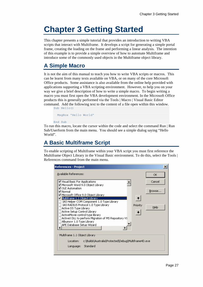
A Basic Multiframe Script To enable scripting of Multiframe within your VBA script you must first reference the Multiframe Object Library in the Visual Basic environment. To do this, select the Tools | References command from the main menu.
Chapter 3 Getting Started
Page 28
Search the list of items displayed in the resulting dialog and find the Multiframe 1.1 Object Library entry. To enable Multiframe simply click in the check box to its left and then press OK to exit the dialog. If the reference is set up correctly you should get the benefits of automatic assistance in the editor as you write your macros or scripts. Amongst other things, this will automatically list the properties and methods of objects as you write VBA code. The VBA subroutine listed below is a simple script that uses Multiframe automation. Type this script into the VBA programming environment.
Sub MyScript() Dim mfApp As New Multiframe.Application Dim myFrame As Multiframe.Frame Set myFrame = mfApp.Frame MsgBox myFrame.Name End Sub
Before running this script, make sure Multiframe is running and a frame has been loaded from disk. Now run this script from the VBA environment, it will display a dialog containing the name of the file open in Multiframe.
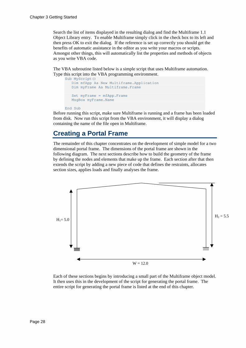
Creating a Portal Frame The remainder of this chapter concentrates on the development of simple model for a two dimensional portal frame. The dimensions of the portal frame are shown in the following diagram. The next sections describe how to build the geometry of the frame by defining the nodes and elements that make up the frame. Each section after that then extends the script by adding a new piece of code that defines the restraints, allocates section sizes, applies loads and finally analyses the frame.
W = 12.0
H1= 5.0 H2 = 5.5
Each of these sections begins by introducing a small part of the Multiframe object model. It then uses this in the development of the script for generating the portal frame. The entire script for generating the portal frame is listed at the end of this chapter.

Chapter 3 Getting Started
Page 29
Adding Nodes and Elements The geometry of a frame is constructed by adding new nodes and elements to the frame. These are created using the AddNode and AddElement methods of the Nodes and Elements collections. The script shown below uses these methods and objects to create the portal frame described above.
Sub CreatePortal() Dim mfApp As New Multiframe.Application Dim myFrame As Multiframe.Frame Dim myNode as Multiframe.Node Dim myEl as Multiframe.Element ‘Add nodes to frame Set myNode = myFrame.Nodes.AddNode(0.0,0.0,0.0) Set myNode = myFrame.Nodes.AddNode(0.0,5.0,0.0) Set myNode = myFrame.Nodes.AddNode(6.0,5.5,0.0) Set myNode = myFrame.Nodes.AddNode(12.0,5.0,0.0) Set myNode = myFrame.Nodes.AddNode(12.0,0.0,0.0) ’Add Elements by joining nodes Set myEl = myFrame.Elements.AddElement(1,2) Set myEl = myFrame.Elements.AddElement(2,3) Set myEl = myFrame.Elements.AddElement(3,4) Set myEl = myFrame.Elements.AddElement(4,5) End Sub
After the declaration of variables, the script creates the five nodes required to define the portal frame. Each node is created via a single call to the AddNode method which returns a reference to the object that represents the new node. This reference is assigned to the myNode variable that is declared at the start of the script as a Node object. After the nodes have been created, each of the elements representing the members of the portal frame are created by calling the AddElement method, which, like the AddNode method, returns a reference to the object representing the new element. This code assumes that the new nodes are the only nodes in the frame as it requires the nodes be numbered from 1 to 5. It is not always necessary to create the nodes and then add elements as elements can be created directly by specifying the coordinates at each end of the element. Hence, the piece of code above could be refined to
Sub CreatePortal() Dim mfApp As New Multiframe.Application Dim myFrame As Multiframe.Frame Dim myEl as Multiframe.Element ‘Create elements Set myEl=myFrame.Elements.AddElement(0.0,0.0,0.0,0.0,5.0,0.) Set myEl=myFrame.Elements.AddElement(0.0,5.0,0.0,6.0,5.5,0.) Set myEl=myFrame.Elements.AddElement(6.0,5.5,0.,12.0,5.0,0.) Set myEl=myFrame.Elements.AddElement(12.0,5.0,0.,12.0,0.,0.) End Sub
which is far more efficient as it reduces the number of subroutine calls made to Multiframe. When creating elements in this way, Multiframe determines if a node already exists at the specified points and connects the element to the existing node. Otherwise a new node is created to define the end of the element.

Chapter 3 Getting Started
Page 30
Properties of Elements Each element within a structure is represented by an Element object. This object can be used to modify the attributes of an element such as its label, end releases or section size. All the Element objects representing the elements of a frame are contained within an Elements collection in the Frame. The Elements collection is arranged in numerical order such that element number 4 is the 4th element in the collection. A reference to the object representing this element would be obtained from the collection as follows
Dim myEl as Multiframe.Element Set myEl = mfApp.Frame.Elements(4)
All attributes of this element that can be set in Multiframe can also be accessed and modified using the Element object. For example, the orientation and label of the element could be set using the following two lines of code.
myEl.Orientation = 45 ‘Set orientation to 45 degrees myEl.Label = ”Beam B2” ‘Set label
The section type associated with an element is set using the SetSection method of the Element object. This method can take a number of different parameters that are used to specify a section from the current sections library. The first and simplest method is to specify the section by the number of the group and the number of the section within the group. The section can also be specified by name, in which case the entire sections library is searched in order to match the name of the section. Examples of each of these methods are
Call myEl.SetSection(1,2) Call myEl.SetSection(“310UB40”) ‘Australia Call myEl.SetSection(“W40x480”) ‘United States Call myEl.SetSection(“150x150x7x10”) ‘Japan
For the portal frame created above, the following piece of code is used to set the section size of each element.
‘Set section size of each element With mfApp.Frame Call .Elements(1).SetSection(1, 1) Call .Elements(2).SetSection(2, 1) Call .Elements(3).SetSection(2, 1) Call .Elements(4).SetSection(1, 1) End With
In this code fragment, the section size is set by specifying the index of the group and section. This allows the script to work with any sections library.
Applying Restraints In Multiframe, restraints are not implemented as properties of a node. Instead, they are considered as a separate entity that is associated with a particular node. In this way, several restraints can be applied to a single node. This is reflected in the Multiframe automation model in which each restraint applied to a node is represented by a separate Restraint object. The object contains the attributes of a restraint such as the node to which is applied and the degrees of freedom it restrains. All the restraints within a structure are stored in the Restraints collection in the Frame object.

Chapter 3 Getting Started
Page 31
A new restraint can be applied to a structure by adding a new object to the Restraints collection using the AddRestraint method. This method takes two parameters; the first parameter specifies the node at which the restraint is to be applied. The second parameter specifies the degrees of freedom to be restrained. This parameter can take many forms but the simplest means of identifying the restrained freedoms is using constants representing common type of restrains. For the portal frame we are developing in the example, we need to apply rigid restraints at the 1st and 5th node in the frame. These restraints are added to the model using the following code.
Dim myRestraint as Multiframe.Restraint With mfApp.Frame.restraints Set myRestraint = .AddRestraint(1, mfRestraintFixed) Set myRestraint = .AddRestraint(5, mfRestraintFixed) End With
VBA and Office 97 The VBA language provided in Microsoft Office 2000 contains a number of improvements to the version used within the Office 97 suite of products. A significant difference is in the use of enumerated types. The Multiframe automation interface uses many enumerated types to make programming scripts much simpler when using the latest versions of VBA. However, when programming using an older version of VBA, such as used in Office 97, the use of enumerated types is not supported and the enumerated constants must be replaced with their integer value. The enumerated types and their values are summarised in Appendix A of this document. If you were using Office 97, the above script would need to be programmed using a value of 2 instead of enumerated constant mfRestraintFixed. You can also import the list of types from the Types module contained in the Office 97 examples provided with Multiframe.
Applying Loads A load case applied to a frame is represented within the Multiframe object model using the Loadcase object. This object contains the attributes of a load case such as its name, type, etc. It also contains several collections containing the loads applied in the load case. All the load cases applied to a structure are stored in a Loadcases collection that is contained within the Frame object. A new load case is added to a frame using the AddCase method of this collection. This method takes two parameters that specify the type and name of the load case. The following code fragment is used in the portal frame script to define three load cases, a self weight case, a live load case and a factored case that combines the first two cases.
Dim myLC as Multiframe.Loadcase 'Add load cases to frame With mfApp.Frame.LoadCases Call .Item(1).Delete Set myLC = .AddCase(mflcSelfWeight, "Self Weight") Set myLC = .AddCase(mflcStatic, "Live Load") Set myLC = .AddCase(mflcCombined, "DL + 1.25*LL") End With

Chapter 3 Getting Started
Page 32
Loads applied to elements within a model are represented by an ElementLoad object. This object has properties representing the magnitude of the load and its position along the element. All the element loads applied in a load case are contained in an ElementLoads collection that is stored in the Loadcase object. New loads are added to a load case by adding an item to this collection using the AddLoad method.
Dim myLoad as Multiframe.ElementLoad 'Define live loads With mfApp.Frame.LoadCases(2) .ElementLoads Set myload=.AddLoad(2,mfDOFy,mfLoadshapeUniform,-3.5,0,-3.5,0,False) Set myload=.AddLoad(3,mfDOFy,mfLoadshapeLinear,-3.5,0,-1.5,0, False) End With
A similar syntax is used to add other loads such as thermal, joint loads or prescribed displacements. The load case factors used to define a combined load case are also stored as properties of the Loadcase object. They can be set using the Factor property of this object which, unlike many properties, takes a single parameter that identifies the index of the load case for which the load case factor is being set. In our portal frame example, this property is used as follows.
'Set factors for combined load case With mfApp.Frame.LoadCases(3) .Factor(1) = 1# .Factor(2) = 1.25 End With
This snippet of code defines the factors for the 3rd load case that is a combination of the 1st load case and 1.25 time the 2nd load case.
Running an Analysis The frame currently open in Multiframe can be analysed using the Analysis object. This object manages the setting for each of the different analyses, records which analyses are to be performed, and executes the analysis. The following code fragment is used to perform a linear analysis of the portal frame.
'Perform linear analysis With mfApp.Frame.Analysis .Linear = True .Nonlinear = False .Analyse End With
This code accesses the Linear and Nonlinear properties of the Analysis object to set which analyses are to be performed. The analysis is then executed within Multiframe by calling the Analyse method.

Chapter 3 Getting Started
Page 33
Units In this example we have so far avoided the mention of which units we are using to construct the frame. This has been deliberate as the units used when scripting the VBA can be any unit supported within Multiframe. In fact, when working with the automation interface, all values are specified using the current units set that is been used within the application. The units may be interrogated or manipulated using the Preferences object. The Units property of the Preferences object specifies the current unit set. This may be set to one of predefined sets of units (Australian, Japanese, American, etc.) by setting it to an enumerated value of type mfUnitSets. For example, the Japanese unit set may be specified by setting
mfApp.Preferences.UnitSet = mfUnitsetJapanese
The specific units used with a unit set can be manipulated via the SetUnit method of the Preferences object. This method takes two parameters; the first is an enumerated value identifying the type of units (length, force, angle, etc) to be set. The second parameter is a string that specifies the name of the units to be used. For example, to change the units for length to feet would require the code
mfApp.Preferences.SetUnits(mfUnitLength,”ft”) Allowable values of the unit names are those listed in Multiframe’s Units dialog for each of the units types. For the portal frame script, metric units have been adopted. This is done by inserting the following piece of code at the start of the script following the declaration of variables.
'Set units With mfApp.Preferences .UnitSet = mfUnitsetAustralian Call .SetUnit(mfUnitLength, "m") Call .SetUnit(mfUnitForce, "kN") End With
This short piece of code specifies to use the Australian unit set and then ensures that the length and force units are set to metres and kilonewtons respectively.
The Final Script In the preceding sections a script was developed for generating a simple portal frame. Each section developed a separate piece of the script. All of these pieces combine into a single script that is listed below.
Public Sub CreatePortal() 'Declare variables Dim mfApp As New Multiframe.Application Dim myLC As Multiframe.LoadCase Dim myEl As Multiframe.Element Dim myLoad As Multiframe.ElementLoad Dim myRest As Multiframe.Restraint 'Set units With mfApp.Preferences .UnitSet = mfUnitsetAustralian Call .SetUnit(mfUnitLength, "m") Call .SetUnit(mfUnitForce, "kN")

Chapter 3 Getting Started
Page 34
End With 'Create elements forming portal frame With mfApp.Frame.Elements Set myEl = .AddElement(0#, 0#, 0#, 0#, 4#, 0#) Set myEl = .AddElement(0#, 4#, 0#, 6#, 5.25, 0#) Set myEl = .AddElement(6#, 5.25, 0#, 12#, 4#, 0#) Set myEl = .AddElement(12#, 4#, 0#, 12#, 0#, 0#) End With 'Set section type of each element With mfApp.Frame Call .Elements(1).SetSection(1, 1) Call .Elements(2).SetSection(2, 1) Call .Elements(3).SetSection(2, 1) Call .Elements(4).SetSection(1, 1) End With 'Apply restraints to base of columns With mfApp.Frame.restraints Set myRest = .AddRestraint(1, mfRestraintFixed) Set myRest = .AddRestraint(5, mfRestraintFixed) End With 'Add load cases to frame With mfApp.Frame.LoadCases Call .Item(1).Delete Set myLC = .AddCase(mflcSelfWeight, "Self Weight") Set myLC = .AddCase(mflcStatic, "Live Load") Set myLC = .AddCase(mflcCombined, "DL + 1.25*LL") End With 'Define live loads With mfApp.Frame.LoadCases(2).ElementLoads Set myLoad = .AddLoad(2, mfDOFy, mfLoadshapeUniform, -3.5, 0, -3.5, 0, False) Set myLoad = .AddLoad(3, mfDOFy, mfLoadshapeLinear, -3.5, 0, -1.5, 0, True) End With 'Set factors for combined load case With mfApp.Frame.LoadCases(3) .Factor(1) = 1# .Factor(2) = 1.25 End With 'Perform linear analysis With mfApp.Frame.Analysis .Linear = True .Nonlinear = False .Analyse End With End Sub

Chapter 4 Modelling the Frame
Page 35
Chapter 4 Modelling the Frame This chapter describes the objects that are used to develop the structural model. These include objects describing nodes, elements, restraints and springs. These object form part of a hierarchy contained within the Frame object that encapsulates the objects describing an entire structural model and its associated properties. This chapter does not cover the objects for applying loads to the structural model which are described in Chapter 5.
Frame Object The Frame object is a very important object as it contains all the objects and collects which describe the frame currently open within the Multiframe application. This includes all elements used to model the geometry of the frame, the loading and the results of analyses performed on the frame. The frame object is also responsible for managing the storage and retrieval of the frame to file. Frame
Nodes (Node)
Elements (Element)
Loadcases (Loadcase)
Restraints (Restraint)
NodeMasses (NodeMass)
NodeLinkGroups (NodeLinkGroup)
Springs (Spring)
Members (Member)
Results
Analysis
ProjectInfo
A summary of all the properties and methods of a Frame object are listed in the table below.
Property Type Description ActiveLoadcase LoadCase Get / Set the load case currently displayed
in the Multiframe application. Analysis Analysis Read Only. Returns an object that manages
the analysis of the frame. Application Application Read Only. Returns a reference to the
parent application.

Chapter 4 Modelling the Frame
Page 36
Property Type Description Elements Elements Read Only. Returns a collection of all
elements in the frame. FullName String Read Only. Returns the name and path of
the file to which the frame is saved. LoadCases LoadCases Read Only. Returns a collection of all load
cases applied to the frame. GroupSets GroupSets Read Only. Returns a collection of all
group sets defined within frame. Members Members Read Only. Returns a collection of all the
frames design members. Modified Boolean Read Only. Returns true if the sections
library has been modified and the changes have not been saved to disk.
Name String Read Only. Returns the name of the file in which the frame is saved.
NodeLinkGroups
NodeLinkGroups Read Only. Returns a collection of all the node link groups applied to the frame.
NodeMasses NodeMasses Read Only. Returns a collection of all the node masses applied to the frame.
Nodes Nodes Read Only. Returns a collection of all the nodes in the frame.
Path String Read Only. Returns the directory path of the file to which the frame is saved.
ProjectInfo ProjectInfo Read Only. Returns an object containing the user definable properties of the frame.
Restraints Restraints Read Only. Returns a collection of all the restraints in the frame.
Results Results Read Only. Returns an object that encapsulates the results from the analysis of the frame.
Selection Selection Read Only. Returns the selection is a specified window.
Springs Springs Read Only. Returns a collection of all the springs in the frame.
Method Returns Description Close Close the frame currently open within the
application. New Close the frame currently open within the
application. Open Loads a frame from file. Save Saves the frame to its original file. SaveAs Saves the frame to a specified file. SetSelection Set the selection in the specified window.

Chapter 4 Modelling the Frame
Page 37
Properties The geometry and topology of a structural model is defined by its nodes and elements. All the nodes and elements in a frame are stored as collections of Node and Element objects. These collections are referenced via the Nodes and Elements properties of the Frame object. Boundary conditions are applied to the model in the form of springs, restraints and the linking of nodal degrees of freedom. These are represented within the object model as Spring, Restraint and NodeLinkGroup objects respectively. The boundary conditions applied to frame are stored in collections of each of these objects which are referenced via the Springs, Restraints and NodeLinkGroups properties of the Frame object. A joint mass attached to the model is defined by the NodeMass object. The NodeMasses collection stores all the node masses applied to a frame. In Multiframe4D, this collection can be referenced from the Frame object using the NodeMasses property. An error message will be returned when trying to access this collection in other versions of Multiframe. The application of Node, Spring, Element, NodeLinkGroup and NodeMass objects in the modelling of a frame are described in detail later in this chapter. The loading applied to the frame is defined by the collection of LoadCases objects associated with the frame. This collection, which is available via the LoadCases property of the Frame object, defines each of the load cases applied to the frame. The application of loads are described in detail in Chapter 5. The Analysis property of the Frame object returns a reference to an Analysis object that is responsible for the analysis of the frame. It stores the settings to be used in the analysis, controls which analyses are to be conducted and performs the actual analysis of the frame. A detailed description of this object is presented in Chapter 6. The results of analyses are stored within the Results object. This is stored as part of the Frame object and can be referenced via the Results property of this object. Chapter 7 describes the Results object which contains a hierarchy of objects for accessing the results at each node, element or design member within the frame. The definition of a design member within the Multiframe object model is stored within a Member object. All the design members within a frame are stored within a collection of Member objects. This collection if referenced via the Members property of the Frame object. The use of design members is described later in this chapter. The Modified property is used to determine if the frame has been changed and needs to be saved. This property returns a value of true if the frame has been altered. It will most commonly be used conjunction with the methods to open and save the frame. The details of the frame such as it title, description and name of the client are stored in a ProjectInfo object. This object may be referenced via the ProjectInfo property of the Frame object. The three properties FullName, Name, and Path describe the location of the file to which the frame is saved. The Path property contains the disk path of the file; the Name property returns just the name of the file while the FullName property returns the name of the file including the path.

Chapter 4 Modelling the Frame
Page 38
The Selection property of the Frame object returns the selection within one of Multiframes windows. This is a read only property that takes a single parameter that identifies the window containing the desired selection. If no window is specified, the selection in the window which is currently active within Multiframe is returned. The selection is returned as a Selection object that is discussed in Chapter 10. The ActiveLoadCase property provides a means of interacting with the Multiframe user interface. This property references the load case that is displayed within Multiframes windows.
Methods A new frame is loaded into Multiframe using the Open method of the Frame object. The following script demonstrates how to open a new frame using VBA and Microsoft Excel. In this example the user is prompted to select the file to be opened via the File Open dialog.
Dim Filename As String 'name of file to open Dim Filter As String ‘filter for section library files ’Display open file dialog so user can pick new frame Filter = "Sections Library (*.mfb),*.mfb” With Application Filename =.GetOpenFilename(Filter,, "Open Frame",,False) End With If Filename <> False ThenCall mfApp.Frame.Open(Filename) End If
In Microsoft Word this script would be slightly different as a different function is used to display the File Open dialog.
’Display open file dialog so user can pick new frame With Application.Dialogs(wdDialogFileOpen) .Name = "*.mfb" If (.Display = -1) Then ’Open new sections frame Call mfApp.Frame.Open(.name,true) End If End With
The frame may be saved to file using the Save or SaveAs methods. The Save method saves the frame using it’s current file name and path. The SaveAs method saves the frame as a new file. It would be implemented within a script in a similar was to the examples shown above for opening a frame. The frame currently opened within Multiframe can be closed and a new frame created using with the Close or New methods. Both these methods take a single Boolean parameter that specifies if the existing frame is to be saved. Finally, the SetSelection method sets the selection within a specified window. This method is discussed in detail in Chapter 10.
Nodes A node within a structure is represented by the Node object. This object encapsulates all the properties of a node such as its position and orientation of the local axes. All the nodes that form a structure are contained within the Nodes collection that is stored as part of the Frame object.

Chapter 4 Modelling the Frame
Page 39
Frame
Nodes (Node)
A summary of all the properties and methods of the Node object are listed in the table below.
Property Type Description Elements ElementList Read Only. Returns a list of all elements
connected to the node. Masses NodeMassLi
st Read Only. Returns a list of all node masses attached to the node.
Orientation Variant Get/Set the orientation of the local nodal axes. OrientX Double Get/Set the rotation about the x-axes that
specifies the orientation of the nodes local axes. OrientY Double Get/Set the rotation about the y-axes that
specifies the orientation of the nodes local axes. OrientZ Double Get/Set the rotation about the z-axes that
specifies the orientation of the nodes local axes. Pinned Boolean Get/Set the whether the node is pinned or rigid. Restraints RestraintList Read Only. Returns a list of all restraints applied
to the node. Springs SpringList Read Only. Returns a list of all springs attached
to the node. XYZ Variant Get/Set the position of the node. X Double Get/Set the x-coordinate of the nodes position. Y Double Get/Set the y-coordinate of the nodes position. Z Double Get/Set the z-coordinate of the nodes position. UserData Variant Get/Set user defined value stored with the node. UserDataUnits
mfUnitType Get/Set the units of the user defined value stored with the node.
Method Returns Description GlobalToLocal Variant Transforms a vector of values from
global to local nodal coordinates. Loads NodeLoadList Returns the loads applied to the node by
specified load cases. LocalToGlobal Variant Transforms a vector of values from local
nodal coordinates to global coordinates. PreDisps NodePreDispList Returns the prescribed displacements
applied to the node by specified load cases.
Results NodeResult Returns the results at the node for a specific analysis and load case.
GetUserData Variant Returns variant arrays containing the values and units of the specified user data fields.
Chapter 4 Modelling the Frame
Page 40
Method Returns Description SetUserData Variant Sets the values and units of the specified
user data fields. The Application, Frame, Number, Label and Index properties in addition to the Delete method are common to many objects and are described in Chapter 2.
Creating Nodes A node is added to a frame using the AddNode method of the Nodes collection. This method has three parameters that specify the x, y and z coordinates of the node in the global coordinate system. The y and z parameters are optional values and have a default value of 0.0. The position of the node will be set using the current units of length that are set within the Multiframe application. For example, the following demonstrates how to add a node to a structure.
Dim myNode as Multiframe.Node Dim xVar,yVar as Variant ’Set units to metres Call mfApp.Preferences.SetUnit(mfUnitLength, "m") ’Add node at x=1,y=4,z=5 Set myNode = myFrame.Nodes.AddNode(1.0, 4.0, 5.0)
In this example, the script sets the unit lengths to metres before adding the node. Adding nodes one by one can be tedious and very time consuming using automation. A virtually unlimited number of nodes can be created using the AddNodes method of the Nodes collection. This method also has three parameters corresponding the coordinates in the global x, y and z directions, and returns a NodeList object containing each of the nodes added to the structure. Each of the parameters to this method may be an array of values, containing a value for each of the new nodes, or a single value that will be applied to each of the new nodes. The parameters for the y and z parameters are optional and have a default value of 0.0. This is very convenient when working on a 2D structure or even a continuous beam as the redundant direction can be ignored. Some examples of using the AddNodes method follow.
Dim myNodeList as New Multiframe.NodeList Dim xVar,yVar as Variant ’Set units to metres Call mfApp.Preferences.SetUnit(mfUnitLength, "m") 'Add nodes for a 3 element continuous beam 12 units long Set myNodeList = myFrame.Nodes.AddNodes(Array(0.0, 4.0, 8.0, 12.0)) 'Add nodes for a portal frame, 12 m wide, 4m/5.25m high xVar = Array(0.0,0.0,6.0,12.0,12.0) ‘x coords yVar = Array(0.0,4.0,5.25,4.0,0.0) ‘y coords Set myNodeList = myFrame.Nodes.AddNodes(xVar, yVar)
A feature of Multiframe is that only a single node can exist at any point in space. When adding a node to the structure, Multiframe will test for the existence of a node at the specified location. If such a node exists, a new node will not be created, and the existing node will be returned to the user instead.
Chapter 4 Modelling the Frame
Page 41
Automatically create nodes when adding Elements. When creating the geometry of a frame it is not necessary to specify the individual nodes and then add elements by connecting the individual nodes. A simpler method is to directly create elements by specifying the location of its ends. In this case, nodes will automatically be added to the frame if a node does not already exist at the specified location.
Properties The Node object encapsulates the data describing a joint within a structural model. These properties described the position of the node, the orientation of the nodes local axes and if the node is pinned or rigid. The Node object also provides several other properties that provide information about other items that are connected or associated with the node such as springs, restraints and joint masses. The position of a node in global space is specified using the x, y or z properties of the Node object. These properties, which give the location of the node in each of the global directions, are expressed in terms of the length units currently in use within the Multiframe application. The coordinates of the node may also be referenced using the xyz property that returns the position of the node as a variant containing an array of three values.
Dim myNode as Multiframe.Node ’Get reference to node Set myNode = myFrame.Nodes(21) ’Scale x coord of node by 4 times myNode.x = myNode.x * 4.0 ’Set position of node myNode.xyz = Array(10.0,2.0,1.0)
The orientation of a node is controlled by the OrientX, OrientY, OrientZ properties of the Node object. They define the rotations of the global axes that are combined to give the orientation of the local nodal axes. To complement these three properties, the Orientation property provides access to the same information as an array of three values. The Pinned property of the Node object defines if a node as pinned or rigid. This Boolean valued property is equal to true when the node is a pinned node. A list of the springs attached to a node can be obtained using the Springs property of the Node object. This read only property returns a SpringList object which references each spring applied to the node. The springs attached to several nodes within a structure can be determined using the Springs property of the NodeList object which returns a SpringList object containing all the springs connected to any node contained within the list of nodes.

Chapter 4 Modelling the Frame
Page 42
Dim myNodeList as New Multiframe.NodeList Dim mySpringList as New Multiframe.SpringList ’Get all nodes connected to node 15 Set mySpringList = myFrame.Nodes(15).Springs ’Get all springs connected to nodes 1,2 and nodes 5 to 10 myNodeList.Add “1,2,5-10” Set mySpringList = myNodeList.Springs ’Get all springs in frame myNodeList.Clear myNodeList.Add myFrame.Nodes Set mySpringList = myNodeList.Springs
Similarly the Restraints and Masses properties return list of any restraints or node masses attached to a node. The UserData and UserDataUnits properties enable values other than those defined within Multiframe to be stored with each node. These properties take a single parameter identifying separate values to be stored with the node thus allowing any number of values to be stored with each node. Furthermore, each value is stored as a variant data type so that strings, numbers or even arrays may be stored with each user data entry. To provide compatability of the user data with the handling of units within Multiframe the type of units associated with each user data entry may be set using the UserDataUnits property. By default each user data value is assumed to be dimensionless. A simple example demonstrating these properties if shown below
Dim myNode as Multiframe.Node ’Get reference to node Set myNode = myFrame.Nodes(21) ’Store user data values myNode.UserData(1) = 12.5 ‘ number myNode.UserData(2) = “ABC” ‘ string myNode.UserData(3) = 6.0 ‘ Length value myNode.UserDataUnits(3) = mfUnitsLength msgbox “User Data 1 = ”+ myNode.UserData(1) msgbox “User Data 2 = ”+ myNode.UserData(2) msgbox “User Data 3 = ”+ myNode.UserData(3)
Note units conversions will only be applied to user data values represented as numbers.
Methods A list of loads applied to a node can be obtained using the Loads and PreDisps methods of the Nodes object. These methods take a single parameter identifying the load cases that are to be considered when compiling the list of loads. This parameter is optional, and, if omitted, this method will return all the loads applied to the node as part of any load case within the frame. The Loads and PreDisps methods return the list of loads as NodeLoadList or NodePreDispList objects respectively. The flexibility of these methods is demonstrated below

Chapter 4 Modelling the Frame
Page 43
Dim myNode As Multiframe.Node Dim myLoadList As New Multiframe.NodeLoadList Dim myDispList As New Multiframe.NodePreDispList 'Get reference to node 5 Set myNode = myFrame.Nodes(5) 'Get all loads applied to node 5 in load case 1 Set myLoadList = myNode.Loads(1) 'Get all prescribed disps applied to node 5 in load case 3 Set myDispList = myNode.PreDisps(myFrame.LoadCases(3)) 'Get all loads applied to node 5 in load cases 1 to 3 and 5 Set myLoadList = myNode.Loads("1-3,5") 'Get all loads applied to node 5 (all load cases) Set myLoadList = myNode.Loads(myFrame.LoadCases)
The Results method of the Node object provides a means of directly accessing the results at a node from a particular analysis, without navigating through the hierarchy of the Results object. This method takes three parameters; the first is a variant parameter identifying the load case for which the results are required, the second identifies the type of analysis. The third parameter is redundant and has been included for future expansion of the automation interface. The Results method returns a NodeResult object that encapsulates access to the displacements and reactions at the node. This object is described in detail in Chapter 7. The Node object also provides two methods for transforming an array of values between global and local nodal coordinates. These methods can transform arrays containing either 3 or 6 values. The GlobalToLocal method, as the name suggests, transforms values from the global coordinate system to the local nodal coordinates as defined by the nodal orientation. Conversely, the LocalToGlobal method transforms values expressed in the local nodal coordinates back to global coordinates. A typical application of transforming values between coordinate systems is in transforming the reactions (expressed in global coordinates) at a node with an inclined restraint to determine the reactions normal to the restraint.
Dim myNode As Multiframe.Node Dim r As Variant Set myNode = myFrame.Nodes(1) ’Get vector of nodal reactions wrt global axes r = myNode.Results(1, mfAnalysisStatic).Reactions ’Tranform reactions to local nodal axes r = myNode.GlobalToLocal(r)
Elements The Element object represents an element within a structure. This object encapsulates all the properties of an element such as its position, section type, end releases and orientation of the local axes. All the elements that form a structure are contained within the Elements collection that is stored as part of the Frame object.
Frame
Elements (Element)

Chapter 4 Modelling the Frame
Page 44
A summary of all the properties and methods of the Element object are listed in the table below.
Properties Type Description FlipSectionXX Boolean Get/Set whether the elements
section is flipped about its x-axis. FlipSectionYY Boolean Get/Set whether the elements
section is flipped about its y-axis. Length Double Read Only. Returns the length of
the element. Member Member Read Only. Get the design member
to which the element is part of. Node* Node/Variant Get/Set the node at a specified end
of the element. Nodes NodeList Read Only. Returns a list of all
nodes connected to the element. Offset* Variant Get/Set the rigid offsets at a
specified end of the element. OffsetsLocal Boolean Get/Set whether the end offsets are
defined in local or global coordinates.
Orientation Double Get/Set the orientation of the element.
Releases* Variant Get/Set the releases at the ends of the element.
Section Section/Variant Get/Set the section. Slope Double Read Only. Get the slope of the
element. SlopeXY Double Read Only. Get the slope of the
element in the X-Y plane. SlopeZX Double Read Only. Get the slope of the
element in the Z-X plane. SlopeZY Double Read Only. Get the slope of the
element in the Z-Y plane. Type mfElementTyp
e Get/Set the type of the element.
UseDynamicSelfWeight
Boolean Get/Set whether the self-weight of the element is to be considered in dynamic analyses.
UseShearAreaY Boolean Get/Set whether the shear deflection in the local y-axis is to be considered in an analysis.
UseShearAreaZ Boolean Get/Set whether the shear deflection in the local z-axis is to be considered in an analysis.
UseStaticSelfWeight Boolean Get/Set whether the self-weight of the element is to be considered in static analyses.
XYZ* Variant Read only. Returns the position of

Chapter 4 Modelling the Frame
Page 45
Properties Type Description a specified end of the element.
X* Double Read only. Returns the x-coordinate of a specified end of the element.
Y* Double Read only. Returns the y-coordinate of a specified end of the element.
Z* Double Read only. Returns the z-coordinate of a specified end of the element.
UserData Variant Get/Set user defined value stored with the element.
UserDataUnits mfUnitType Get/Set the units of the user defined value stored with the element.
*Denotes a property that takes a parameter specifying an end of the element.
Method Returns Description GlobalToLocal Variant Transforms a vector of values from global
to local element coordinates. Loads NodeLoadList Returns the loads applied to the element by
specified load cases. LocalToGlobal Variant Transforms a vector of values from local
element coordinates to global coordinates. Results ElementResult Returns the results at the element for a
specific analysis and load case. SetSection Sets the section type of the element. Subdivide ElementList Subdivides the element and returns a list of
the elements that form the original element.
ThermalLoads ThermalLoadList
Returns the thermal loads applied to the element by specified load cases.
GetUserData Variant Returns variant arrays containing the values and units of the specified user data fields.
SetUserData Variant Sets the values and units of the specified user data fields.
The Application, Frame, Number, Label and Index properties as well as the Delete method are common to many objects and are described in Chapter 2.
Chapter 4 Modelling the Frame
Page 46
A note on Properties The properties of an object are most commonly used without any parameters. However, properties may be defined to accept a parameter in much the same way that a method accepts parameters. Unlike methods, these properties can be directly set equal to a value. These types of properties have been used in the Multiframe automation interface to provide a simple means of accessing some properties. A common use is for the properties of an element that pertain to a particular end of the element. These are accessed via a single property of the Element object that accepts a single parameter identifying an end of the element. One such example is the rigid offsets at the end of an element; the offset at the first node can be set using the following code
MyFrame.Elements(1).Offset(1)=Array(1.0,0.0,0.0)
Adding Elements A new element is added to the frame using the AddElement method of the Elements collection. This method accepts up to six parameters that specify either the nodes at each end of the element or the x, y and z coordinates of the ends in the global coordinate system. When adding the element via it’s end coordinates the position of the element will be set using current units of length that are set within the Multiframe application. If a node already exists at one or both of the specified end points, the element will automatically be connected to the existing nodes. If an end point does not exist, a new node will be created at that position. The coordinates of the ends can be specified in three ways; the first uses only the first parameter of the AddElement method and specifies the coordinates as an array of six values. The second method uses two parameters and specifies the coordinates of each end as an array of three values. The final method uses all six parameters and specifies each component of the end coordinates separately. For example, the following demonstrates the different methods for adding an element to a structure by specifying the coordinates at the end of the element.
Dim myEl as Multiframe.Element ’Set units to metres Call mfApp.Preferences.SetUnit(mfUnitLength, "m") With myFrame.Elements ‘Add element between (1,3,0) and (1,8,0) Set myEl =.AddElement(1,3,0,1,8,0) ‘Add element between (1,8,0) and (7,9,0) Set myEl =.AddElement(Array(1,8,0), Array(7,9,0)) ‘Add element between (7,9,0) and (12,3,0) Set myEl =.AddElement(Array(7,9,0,12,3,0)) End With
When adding an element between two nodes there are also a number of variations on how the nodes are specified. In this case, the first two parameters can be any combination of variant values representing a node within the model (i.e. the nodes index or the nodes object). This is demonstrated in the following code.

Chapter 4 Modelling the Frame
Page 47
Dim myEl as Multiframe.Element ’Set units to metres Call mfApp.Preferences.SetUnit(mfUnitLength, "m") With myFrame.Elements ’Add element between nodes 1 and 4 Set myEl =.AddElement(myFrame.Nodes(1), myFrame.Nodes(4)) ’Add element between nodes 2 and 6 Set myEl =.AddElement(2,6) End With
A number of elements can be created using the AddElements method of the Elements collection. This method accepts up to six parameters which have the same meaning as the parameters used by the AddElement method. However, each of these parameters may be an array of values for each of the new elements, or a single value that will be applied to each of the new elements.
Dim myElList as New Multiframe.ElementList Dim xVar,yVar as variant xVar = Array(0,0,0,-1,1,0,2,1,0) yVar = Array(5,0,0,4,1,0,7,1,0) With myFrame.Elements ‘Add element between (1,3,0) and (1,8,0) Set myEl =.AddElements(xVar, yVar) ‘Add element between (1,8,0) and (7,9,0) Set myEl =.AddElements(Array(1,8,0), Array(7,9,0)) ‘Add element between points (7,9,0) and (12,3,0) Set myEl =.AddElements(Array(7,9,0,12,3,0)) ’Add element between nodes 1 & 4, 2 & 3, and 3 & 4 Set myEl =.AddElements(Array(1,2,3), Array(2,3,4)) ’Add elements between nodes 1,2,3 and node 5 Set myEl =.AddElements(Array(1,2,3),myFrame.Nodes(5)) End With
In Multiframe only a single element can exist between two specific nodes. When adding an element to the structure, Multiframe will test for the existence of an element between the specified nodes and, if such an element exists, a new element will not be created. Instead the existing element will be returned to the user by the AddElement or AddElements methods.
Chapter 4 Modelling the Frame
Page 48
Properties The section type and orientation of an element are referenced via the Section, Orientation, FlipSectionXX, and FlipSectionYY properties of the Element object. The Section property identifies the Section object that represents the section currently allocated to the element. When setting the Section property, the new section can be specified using a Section object or by its name. In this case Multiframe will search the section library to locate a matching section. Additional functionality for setting the section type is provided by the SetSection method described in the next section. The orientation of the section, expressed in the current angle units, is controlled via the Orientation property. For sections that are not double symmetric, the orientation method is complemented by the FlipSectionXX, and FlipSectionYY properties that provide a means of correctly positioning the section in relation to the element. When these properties are set true, the orientation of the section will be flipped about the specified axis. A simple example setting the section type and orientation of an element is shown below.
Dim myEl as Multiframe.Element Dim s as string ’Get reference to element 12 Set myEl = myFrame.Elements(12) ’Set section type using two different methods myEl.Section = mfApp.SectionsLibrary.Groups(1).Sections(3) myEl.Section = “610UB101” ’Set section orientation myEl.Orientation = 45.0 myEl.FlipSectionXX = true myEl.FlipSectionYY = false ’Notify user of elements section type s = "Element: "+Str(myEl.Index)+” has section type ”+myEl.Section.Name MsgBox s, vbOKOnly, "Multiframe"
The Type property of the Element object in an enumerated value of type mfElementType. It controls the type of the element that may be set as standard (mfEltypeStandard), tension only (mfEltypeTensionOnly), or compression only (mfEltypeCompressionOnly).
Dim myEl as Multiframe.Element ’Set element at tension only myFrame.Elements(6).Type = mfEltypeTensionOnly ’Set element at compression only myFrame.Elements(8).Type = mfEltypeCompressionOnly
The length and slope of an element can be determined from the read-only properties Length, Slope, SlopeXY, SlopeZX, and SlopeZY. The Length property returns the length of the member in the current length units. Note the length of the member is measured between end points defined by the end offsets and is NOT the distance between the nodes defining the element. The four methods for returning the slope of the member return a value in terms of the current angular units set within Multiframe. The Slope method returns the slope of the member in the X-Y plane and corresponds the slope of the elements displayed in the user interface. The other three slope methods return the slope of the element in a specific plane. The SlopeXY returns the slope of the member in the XY plane that is measured from the X to the Y-axes. Similar the SlopeZX and SlopeZY properties return the slope of the element in the ZX and ZY plane respectively, with the angle measured from the Z axis.

Chapter 4 Modelling the Frame
Page 49
Dim myEl as Multiframe.Element Dim s as string ’Get reference to element 10 Set myEl = myFrame.Elements(10) ’Notify user of elements slope in XY plane s = "Slope of Element in XY plane is: "+Str(myEl.SlopeXY) MsgBox s, vbOKOnly, "Element "+Str(myEl.Index) ’Notify user of elements slope in ZX plane s = "Slope of Element in ZX plane is: "+Str(myEl.SlopeZX) MsgBox s, vbOKOnly, "Element "+Str(myEl.Index)
Four properties of the Element object are flags used to control the analysis of the element. The UseDynamicSelfWeight and UseStaticSelfWeight properties are boolean properties controlling the inclusion of an elements mass in an analysis. When UseStaticSelfWeight is set equal to true, the elements self-weight will be accounted for in any self-weight load cases. Similarly, when the UseDynamicSelfWeight property is set true, the elements mass will be considered when performing a modal or time history analysis. The UseShearAreaY and UseShearAreaZ properties control whether or not an elements shear deformation, about a particular axis, is to be accounted for in an analysis. When set true, these properties indicate that an elements shear stiffness will be considered in a static analysis of the structural model. The moment releases at the end of an element are controlled using the Releases property or the Element object. This property takes a single parameter that specifies an end of the member and returns an array of six boolean values representing the release of the end action in the direction of each degree of freedom. When a value in this array is set true, a release is applied to the corresponding degree of freedom. As Multiframe only supports the release of end moments, only the 3rd, 4th and 6th elements of this array are significant. An example on using end releases follows.
Dim myEl as Multiframe.Element ’Get reference to element 9 Set myEl = myFrame.Elements(9) ’Set pinned ends at both ends of element myEl.Releases(1)=Array(false,false,false,true.true,false) myEl.Releases(2)=Array(false,false,false,true.true,false)
The rigid end offsets at the end of a member are encapsulated by Offset property of the Element object. This property also takes a single parameter that specifies an end of the member and returns an array of three values representing the offsets in each direction of the axis system. The axis system in which the offset is applied is specified by the OffsetsLocal property of the Element object. When this property is equal to true, the offsets will be measured in the elements local coordinate system. Otherwise the offsets are computed in the global coordinate system. Each component of the offsets is measured in the current units of length set within Multiframe.

Chapter 4 Modelling the Frame
Page 50
Dim myEl as Multiframe.Element With myFrame ’Apply offsets to both ends element 2 ’Offsets applied 1 unit along length of member .Elements(2).Offset(1) = Array(1.0,0,0) ‘start offset .Elements(2).Offset(2) = Array(-1.0,0,0) ‘end offset .Elements(2).OffsetsLocal = true ’Apply offsets to start element 3 ’Offset applied 1 unit in both global x and y directions .Elements(3).Offset(1) = Array(1.0,1.0,0) ‘start offset .Elements(3).OffsetsLocal = false End With
The node at an end of an element is referenced by the Node property of the Element object. This property takes a single parameter identifying an end of the element. This property returns the Node object corresponding to the node, however a number of alternative values can be used to set this property to a new value. In fact, this property can be set using any variant value that can be interpreted as a node. This includes a Node object, a nodes index within the frame or even it position. To complement the Node property, the Nodes property returns a NodeList object containing all the nodes that define the element.
Dim myEl as Multiframe.Element Dim myNode1, mynode2 as Multiframe.Node ’Get reference to element 12 Set myEl = myFrame.Elements(12) ’Get reference to nodes at each end of member Set myNode1 = myEl.Node(1) ‘Node at start of element Set myNode2 = myEl.Node(2) ‘Node at end of element ’Move end of element lie between nodes 4 and 5 myEl.Node(1) = 4 myEl.Node(2) = 5 ’Move node at element end to position (1.5,2.0,0.0) myEl.Node(1) = Array(1.5,2.0,0.0)
Note when specifying a new end node by its coordinates, Multiframe will search for an existing node and connect the element to that node. If a node does not exist at the specified location, a new node will automatically be created. The position of an elements end can be determined using the X, Y and Z properties of the Element object which each return a single component of the ends position in global coordinates. The XYZ property provides a faster method of accessing all three components of an end position and returns the coordinates as an array of three values. As with the Node property, each of the methods takes a single parameter identifying an end of the element. The UserData and UserDataUnits properties enable values other than those defined within Multiframe to be stored with each element. These properties take a single parameter identifying separate values to be stored with the element thus allowing any number of values to be stored with each Element. Furthermore, each value is stored as a variant data type so that strings, numbers or even arrays may be stored with each user data entry. To provide compatability of the user data with the handling of units within Multiframe the type of units associated with each user data entry may be set using the UserDataUnits property. By default each user data value is assumed to be dimensionless. A simple example demonstrating these properties if shown below
Chapter 4 Modelling the Frame
Page 51
Dim myElement as Multiframe.Element ’Get reference to Element Set myElement = myFrame.Elements(21) ’Store user data values myElement.UserData(1) = 12.5 ‘ number myElement.UserData(2) = “ABC” ‘ string myElement.UserData(3) = 6.0 ‘ Length value myElement.UserDataUnits(3) = mfUnitsLength msgbox “User Data 1 = ”+ myElement.UserData(1) msgbox “User Data 2 = ”+ myElement.UserData(2) msgbox “User Data 3 = ”+ myElement.UserData(3)
Note units conversions will only be applied to user data values represented as numbers. Finally, the Member property returns the Member object corresponding to the design member of which the element is a part.
Methods The SetSection method of the Element object is used to specify the section type of an element. This method takes up to two parameters that specify the section and optionally the group in which it is contained. The section can be identified in a number of ways; the first is simply by the index of the section and the group in which it is contained. In this case the group can be specified by its index within the sections library, its name or by passing a SectionGroup object. The second method of setting the section is to use it’s name. In this case no group is required and Multiframe will search the entire sections library to locate the sections. The final way of setting the section type is to pass a Section object. Some typical uses of this method are shown in the following code.
Dim myEl As Multiframe.Element Dim mySection as Multiframe.Section ’Get reference to element 5 Set myEl = myFrame.Elements(5) 'Set section to the fourth section in the second group Call myEl.SetSection(4,2) 'Set section to sixth section in the group named UB Call myEl.SetSection(6,”UB”) 'Set section to section named 610UB101 Call myEl.SetSection(“610UB101”) 'Set section to fifth section in fourth group using section object. Set mySection = mfApp.SectionsLibrary.groups(4).Sections(5) Call myEl.SetSection(mySection)
As the name suggests, the Subdivide method can be used to split an element into a number of smaller elements. The method takes a single a single parameter that specifies the proportions into which the element will be split. This parameter can be used in two ways; if a single integer value is passed the element will be split into the specified number of elements of equal length. Alternatively, the element may be split into arbitrary size elements by passing an array containing the relative size of each of the subdivided elements. For example;

Chapter 4 Modelling the Frame
Page 52
Dim myEllist As Multiframe.ElementList ’Split element 5 into 4 equal size elements Set myEllist = myFrame.Elements(5).Subdivide(4) ’Split element 3 into 3 elements ’End quarters of the element will be made into separate elements. Set myEllist = myFrame.Elements(3).Subdivide(Array(1,2,1))
The Subdivide method returns an ElementList object containing the elements into which the original element was split. A list of loads applied to an element can be obtained using the Loads and ThermalLoads methods of the Element object. These methods take a single parameter identifying the load cases that are to be considered when compiling the list of loads. This parameter is optional, and, if omitted, this method will return all the loads applied to the element as part of any load case within the frame. The Loads and ThermalLoads methods return the list of loads as ElementLoadList or ThermalLoadList objects respectively. The flexibility of these methods is demonstrated below
Dim myEl As Multiframe.Element Dim myLoadList As New Multiframe.ElementLoadList Dim myThermLoadList As New Multiframe.ThermalLoadList 'Get reference to element 5 Set myEl = myFrame.Elements(5) 'Get all loads applied to element 5 in load case 1 Set myLoadList = myEl.Loads(1) Add to list the loads applied in the load case named “Live Loads” myLoadlist.Add myEl.Loads(“Live Loads”) 'Get all thermal loads applied to element 5 in load case 3 Set myThermLoadList = myNode.PreDisps(myFrame.LoadCases(3)) 'Get all loads applied to element 5 in load cases 1 to 3 and 5 Set myLoadList = myNode.Loads("1-3,5") 'Get all loads applied to element 5 (all load cases) Set myLoadList = myNode.Loads(myFrame.LoadCases)
The Results method of the Element object provides a means of directly accessing the results at a element from a particular analysis, without navigating through the hierarchy of the Results object. This method takes three parameters; the first is a variant parameter identifying the load case for which the results are required, the second identifies the type of analysis. The third parameter is currently redundant and has been included for future expansion of the automation interface. The Results method returns an ElementResult object that encapsulates access to the elements actions and displacements. This object is described in detail in Chapter 7. The Element object also provides two methods for transforming an array of values between global and local coordinates. These methods can transform arrays containing either 6 or 12 values. The GlobalToLocal method, as the name suggests, transforms values from the global coordinate system to the elements local coordinates as defined by the its orientation. Conversely, the LocalToGlobal method transforms values expressed in the elements local coordinates back to global coordinates. A typical application of transforming values between coordinate systems is in transforming the displacements (expressed in global coordinates) at a node to values expressed in terms of an elements local coordinate system.

Chapter 4 Modelling the Frame
Page 53
Dim myEl As Multiframe.Element Dim r As Variant ’Get reference to element 1 Set myEl = myFrame.Elements(1) ’Get vector of nodal displacements wrt global axes r = myEl.Node(1).Results(1, mfAnalysisStatic).Disps ’Tranform reactions to local element axes r = myEl.GlobalToLocal(r)
Restraints Each restraint applied to a node within a Multiframe structural model is represented by a Restraint object. All of the restraints applied to the structural model are listed within a Restraints collection that is stored as part of the Frame object.
Frame
Restraints (Restraint)
A summary of all the properties and methods of the Restraint object are listed in the table below.
Property Type Description Code Variant Read Only. Returns an array of values identifying
the restrained degrees of freedom applied by the restraint.
DOF Boolean Get/Set whether a specific degree of freedom in restrained.
Global Boolean Get/Set whether the restraint is applied in the global or local nodal coordinate system.
Kind String Get/Set the kind of the element. Node Node/Variant Get/Set the node to which the restraint is applied. Type mfRestraintTyp
e Get/Set the type of restraint.
The Application, Frame, Number, Label and Index properties and the Delete method are common to many objects and are described in Chapter 2.

Chapter 4 Modelling the Frame
Page 54
Restraining Nodes A new spring can be attached to a node by calling the AddRestraint method of the Restraints collection. This method has two parameters that specify the node to which the restraint is to be attached and the degrees of freedom to be restrained. The node to which the restraint is applied is passed as a variant parameter and so the node can be identified using either its index or by using a Node object. The degrees of freedom to be restrained at a node can be described in three ways. The simplest method is by name, which allows standard restraints such as rollers, pinned, or rigid restraints to be applied very easily. Standard restraints can also be identified by an enumerated value of type mfRestraintType. The last technique allows each degree of freedom to be individually restrained. The names and enumerated values describing the standard type of restraints are described later in this section. The following code demonstrates the different parameters that can be used when adding a restraint to a node.
Dim myRest As Multiframe.Restraint With = myFrame.Restraints ’Add pinned restraint to node 1 Set myRest =.AddRestraint(1,Array(True,True,True,False,False,False)) ’Add roller restraint to node 2 Set myRest =.AddRestraint(2,mfRestraintPinnedxRoller) ’Add rigid restraint to node 3 Set myRest = .AddRestraint(3, "Rigid") End With
Properties The Node property of the Restraint object identifies the node to which the restraint is attached. This property, which provides a reference to a Node object, may also be used to change the node to which the restraint is applied. This property may be set equal to any variant value that represents a node. The degrees of freedom restrained by a restraint are specified via the Code property of the Restraint object. This property is an array of six Boolean values, each value corresponding to a degree of freedom at the node to be restrained. When an entry in the array is set true, the corresponding degree of freedom will be restrained. A degree of freedom can also be restrained via the DOF property. This property has a single parameter of type mfDOF that specifies a degree of freedom and has a Boolean value of true if that degree of freedom is restrained. A number of standard restraints may be identified using an enumerated value of type mfRestraintType or by name. These standard types of restraints are listed in the table below. The Type property of the Restraint object is used to specify the type of restraint using the enumerated value. This is complemented by the Kind property that specifies the type of the restraint by name. Both of these properties may be used to set the type of restraint.
Restraint Name mfRestraintType Value Pinned mfRestraintPinned 1 Rigid mfRestraintFixed 2 x Roller mfRestraintPinnedxRoller 3 y Roller mfRestraintPinnedyRoller 4 z Roller mfRestraintPinnedzRoller 5

Chapter 4 Modelling the Frame
Page 55
x Guide mfRestraintRigidxRoller 6 y Guide mfRestraintRigidyRoller 7 z Guide mfRestraintRigidzRoller 8 mfRestraintRotational 9 mfRestraintUnknown 0
The Global property of a restraint determines if the restraint is applied in the global coordinate system of the local coordinate system of the node to which the restraint is applied. All nodes added within Multiframe are by default added in the local coordinate system and it is advisable not to change this property from the value set by Multiframe.
Finding all the Restraints at a Node All the restraints at a node can easily be obtained using the Restraints property of the Node object. This property returns a RestraintList object that contains a reference to every restraint applied to that node. The Restraints property of a NodeList object extends this functionality and returns a RestraintList containing all the restraints attached to any of the nodes in the list. This technique can be applied to determine the associate between many other objects within the model.
Springs A spring attached to a node within a structure is represented by a Spring object. This object encapsulates all the properties of the spring such as its direction and stiffness. All the springs utilised in a structural model are contained within the Springs collection which can be referenced directly from the Frame object using the property of the same name.
Frame
Springs (Spring)
A summary of the properties of the Spring object are listed in the table below.
Property Type Description DOF mfDOF Get/Set the degree of freedom in which the spring
acts. Global Boolean Get/Set whether the spring is directed in the
global or local nodal coordinate system. Kind String Get/Set the kind of the spring. Node Node/Variant Get/Set node to which the spring is attached. Value mfRestraintTyp
e Get/Set the stiffness of the spring.
Chapter 4 Modelling the Frame
Page 56
The Application, Frame, Number, Label and Index properties and the Delete method are common to many objects and are described in Chapter 2.
Adding a Spring A new spring can be attached to a node by calling the AddSpring method of the Springs collection. This method has three parameters that specify the node to which the spring is to be attached, the direction in which the spring acts and its stiffness. The node to which the spring is attached is passed as a variant parameter and so the node can be identified using either its index or by using a Node object. The second parameter is an enumerated value of type mfDOF that identifies the degree of freedom in which the spring acts. The final parameter specifies the stiffness of the spring in terms of the current units of spring stiffness that are set within the Multiframe application. For example, the following code demonstrates how springs may be added to a structure.
Dim mySpring as Multiframe.Spring ’Get springs collection With myFrame.Springs ’Add vertical spring at node 2 Set mySpring = .AddSpring(2,mfDOFy,10.5) ’Add torsional spring at node 5 Set mySpring = .AddSpring(myFrame.Nodes(5), mfDOFthetaz,0.25) End With
A number of springs can be added in a single call to the automation interface using the AddSprings method of the Springs collection. This method takes three parameters that have the same meaning as those passed to the AddSpring method. However, each of the parameters may be an array of values, containing a value corresponding to each new spring, or a single value that will be applied to each of the new springs. Some examples of how this method may be used are shown in the following script.
Dim mySpringList as New Multiframe.SpringList Dim myNodeList as New Multiframe.NodeList Dim stiffness as Variant const DtoR = 3.14159/180.0 ‘Factor to convert degrees to radians With myFrame.Springs 'Add horizontal spring to node 5 Set mySpringList = .AddSprings(5,mfDOFx,5.75) 'Add springs to nodes 1 representing spring inclined at 60 degrees stiffness= Array(5.0*cos(60*DtoR),5.0*sin(60*DtoR)) Set mySpringList = .AddSprings(1,Array(mfDOFx,mfDOFy),stiffness) 'Add springs to nodes 1 to 10 and nodes 15 and 20 Set mySpringList = .AddSprings(“1-10,15,20”,mfDOFthetaZ,6.5) End With
Properties The Spring object encapsulates the data describing a joint spring within a Multiframe structural model. This data, which includes information describing the node to which the spring is attached, the direction of the spring and its stiffness, can be access via the properties of this object.
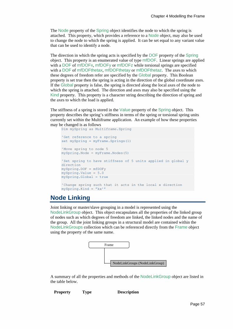
Chapter 4 Modelling the Frame
Page 57
The Node property of the Spring object identifies the node to which the spring is attached. This property, which provides a reference to a Node object, may also be used to change the node to which the spring is applied. It can be set equal to any variant value that can be used to identify a node. The direction in which the spring acts is specified by the DOF property of the Spring object. This property is an enumerated value of type mfDOF. Linear springs are applied with a DOF of mfDOFx, mfDOFy or mfDOFz while torsional springs are specified with a DOF of mfDOFthetax, mfDOFthetay or mfDOFthetaz. The axes to which these degrees of freedom refer are specified by the Global property. This Boolean property is set true then the spring is acting in the direction of the global coordinate axes. If the Global property is false, the spring is directed along the local axes of the node to which the spring is attached. The direction and axes may also be specified using the Kind property. This property is a character string describing the direction of spring and the axes to which the load is applied. The stiffness of a spring is stored in the Value property of the Spring object. This property describes the spring’s stiffness in terms of the spring or torsional spring units currently set within the Multiframe application. An example of how these properties may be changed is as follows
Dim mySpring as Multiframe.Spring ’Get reference to a spring set mySpring = myFrame.Springs(1) ’Move spring to node 5 mySpring.Node = myFrame.Nodes(5) ’Set spring to have stiffness of 5 units applied in global y direction mySpring.DOF = mfDOFy mySpring.Value = 5.0 mySpring.Global = true ’Change spring such that it acts in the local x direction mySpring.Kind = ”kx’”
Node Linking Joint linking or master/slave grouping in a model is represented using the NodeLinkGroup object. This object encapsulates all the properties of the linked group of nodes such as which degrees of freedom are linked, the linked nodes and the name of the group. All the joint linking groups in a structural model are contained within the NodeLinkGroups collection which can be referenced directly from the Frame object using the property of the same name.
Frame
NodeLinkGroups (NodeLinkGroup)
A summary of all the properties and methods of the NodeLinkGroup object are listed in the table below.
Property Type Description

Chapter 4 Modelling the Frame
Page 58
Property Type Description DOF Boolean Get/Set whether a specific degree of freedom is
slaved. Label String Get/Set name of the group. MasterNode
Boolean Get/Set the master node.
Nodes NodeList/Variant
Get/Set the list of the linked nodes.
LinkedDOF Variant Get/Set the slaved degrees of freedom.
Method Returns Description AddNodes Adds nodes to the group. RemoveNodes
Removes nodes from the group
In addition, the Application, Frame, Number and Index properties as well as the Delete method are common to many objects and are described in Chapter 2.
Creating a linked group of Nodes A new master/slave grouping is added to a frame using the AddGroup method of the NodeLinkGroups collection. This method requires four parameters that specify the name of the group, the nodes to be linked in the group, the master node and which degrees of freedom are linked together by the group. The nodes in the group are specified using a variant parameter and so any value representing a group of nodes can be used to specify this list. Typically this will be either an array of indices or a NodeList object. Similarly, the master node is also specified as a variant and as such can be identified by any value representing a single node. The final parameter identifying the slaved degrees of freedom is also a variant parameter but it must contain an array of six Boolean values that correspond to each of the degrees of freedom. The entries in this array should be set as true if the corresponding degree of freedom is to be restrained. The AddGroup method returns the NodeLinkGroup object referencing the new group added to the frame. The following code demonstrates how to add a group of linked nodes to the frame. In this example, all the nodes at y=4.5 are linked together to form a floor with rigid in-plane behaviour.
Chapter 4 Modelling the Frame
Page 59
Dim myGroup As Multiframe.NodeLinkGroup Dim myNodeList As New Multiframe.NodeList Dim dof(1 To 6) As Boolean dof(1) = True dof(2) = False dof(3) = True dof(4) = False dof(5) = True dof(6) = False ' Select all nodes in first floor which is at y=4.5 ' by finding all nodes lying between y=4 and y=5 Set myNodeList = myFrame.Nodes.Find("y", 4, 5) ’ Create the linked group ’ The first node in the list is used as the master node With myFrame.NodeLinkGroups Set myGroup = .AddGroup("Floor 1", myNodeList, myNodeList(1), dof) End With
In this example to Find method of the Nodes collection is used to select the list of nodes to be linked. The Find method is common to most collections and lists in the Multiframe Object Model. It is used to find all the items in the collection or list with a property that meets a specified criterion. In this instance, this method has been used to find all the nodes with a y-coordinate lying between 4 and 5. The Find method is described in detail in Chapter 10.
Properties The Nodes property of the NodeLinkGroup object returns a NodeList object containing each of the nodes in the linked group. This property can also be used to set the nodes in the group and can be set equal to any value that represents one or more nodes such as a NodeList object. The master node for the linked group is identified via the MasterNode property. This property returns the Node object representing the master node. This property can be used to set the master node and can be set equal to any value used to represent a single node such as it’s index or a Node object.
Dim myGroup As Multiframe.NodeLinkGroup Dim myNodeList As New Multiframe.NodeList ' Find all nodes in second floor which is at y=6.5 Set myNodeList = myFrame.Nodes.Find("y", 6.4, 6.6) ’ Reset nodes in the group myFrame.NodeLinkGroups(“Floor 2”).Nodes = myNodeList myFrame.NodeLinkGroups(“Floor 2”).MasterNode = myNodeList(1)
The degrees of freedom linked by the group can be identified via two properties of the NodeLinkGroup object. The DOF property accepts a single parameter identifying a nodal degree of freedom and returns true if that degree of freedom is linked. The SlavedDOF property returns an array of six (6) Boolean values corresponding to each of the nodal degrees of freedom. The entires in this array are set true if the corresponding degree of freedom is linked by the group.

Chapter 4 Modelling the Frame
Page 60
Dim myGroup As Multiframe.NodeLinkGroup Dim myNodeList As New Multiframe.NodeList ’ Reset nodes in group 2 to form rigid wall in XY plane myFrame.NodeLinkGroups(2).DOF(1) = true myFrame.NodeLinkGroups(2).DOF(2) = true myFrame.NodeLinkGroups(2).DOF(3) = false myFrame.NodeLinkGroups(2).DOF(4) = false myFrame.NodeLinkGroups(2).DOF(5) = false myFrame.NodeLinkGroups(2).DOF(6) = true ’ Set linked DOF in group named “Floor 2” myFrame.NodeLinkGroups(“Floor 2”).LinkedDOF = Array(1,0,1,0,1,0)
The name of the group is referenced via the Label property of the NodeLinkGroup object.
Methods Nodes may be added or removed from the linked group using the AddNodes and RemoveNodes methods of the NodeLinkGroup object. These methods take a single variant parameter that specifies the nodes to be added or removed from the group. A simple example demonstrating the various parameters that can be passed to these methods is shown below.
Dim mylist As New Multiframe.NodeList mylist.Add "20-30" With mfApp.Frame.nodeLinkGroups(1) ’Add nodes to linked group Call .AddNodes(1) 'Add node by index Call .AddNodes("2-9,12") 'Add nodes listed by index Call .AddNodes(mfApp.Frame.Nodes(10)) 'Add node using node object Call .AddNodes(mylist) ‘Add nodes using list ‘Remove nodes from linked group Call .RemoveNodes(1) 'By index Call .RemoveNodes("2-9,12") Call .RemoveNodes(mylist) 'Using a list of nodes End With
Node Masses In Multiframe4D, a joint mass attached to a node within a structure is represented by a NodeMass object. This object encapsulates all the properties of the mass such the node to which it is attached and the mass associated with each degree of freedom. All the nodal masses in a structural model are contained within the NodeMasses collection that can be referenced directly from the Frame object using the property of the same name.
Frame
NodeMasses (NodeMass)
A summary of all the properties and methods of the NodeMass object are listed in the table below.
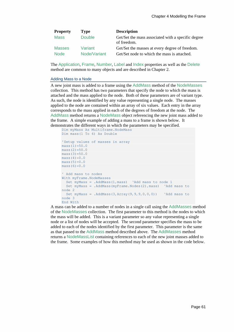
Chapter 4 Modelling the Frame
Page 61
Property Type Description Mass Double Get/Set the mass associated with a specific degree
of freedom. Masses Variant Get/Set the masses at every degree of freedom. Node Node/Variant Get/Set node to which the mass is attached.
The Application, Frame, Number, Label and Index properties as well as the Delete method are common to many objects and are described in Chapter 2.
Adding Mass to a Node A new joint mass is added to a frame using the AddMass method of the NodeMasses collection. This method has two parameters that specify the node to which the mass is attached and the mass applied to the node. Both of these parameters are of variant type. As such, the node is identified by any value representing a single node. The masses applied to the node are contained within an array of six values. Each entry in the array corresponds to the mass applied in each of the degrees of freedom at the node. The AddMass method returns a NodeMass object referencing the new joint mass added to the frame. A simple example of adding a mass to a frame is shown below. It demonstrates the different ways in which the parameters may be specified.
Dim myMass As Multiframe.NodeMass Dim mass(1 To 6) As Double ’Setup values of masses in array mass(1)=50.0 mass(2)=50.0 mass(3)=50.0 mass(4)=0.0 mass(5)=0.0 mass(6)=0.0 ’ Add mass to nodes With myFrame.NodeMasses Set myMass = .AddMass(1,mass) ‘Add mass to node 1 Set myMass = .AddMass(myFrame.Nodes(2),mass) ‘Add mass to node 2 Set myMass = .AddMass(3,Array(9,9,9,0,0,0)) ‘Add mass to node 3 End With
A mass can be added to a number of nodes in a single call using the AddMasses method of the NodeMasses collection. The first parameter to this method is the nodes to which the mass will be added. This is a variant parameter so any value representing a single node or a list of nodes will be accepted. The second parameter specifies the mass to be added to each of the nodes identified by the first parameter. This parameter is the same as that passed to the AddMass method described above. The AddMasses method returns a NodeMassList containing references to each of the new joint masses added to the frame. Some examples of how this method may be used as shown in the code below.

Chapter 4 Modelling the Frame
Page 62
Dim myMassList As New Multiframe.NodeMassList Dim myNodeList As New Multiframe.NodeList Dim mass(1 To 6) As Double ’Setup values of masses in array mass(1)=25.0 mass(2)=25.0 mass(3)=25.0 mass(4)=0.0 mass(5)=0.0 mass(6)=0.0 ’ Add mass to nodes With myFrame.NodeMasses ‘Add mass to a single node Set myMassList=.AddMasses(1,mass) Set myMassList=.AddMasses(myFrame.Nodes(2),mass) ‘Add masses to several nodes Set myMassList=.AddMasses(“3-5”,mass) ‘Nodes 3 to 5 myNodeList.Add “6-8” Set myMassList=.AddMasses(myNodeList,mass) ‘Nodes 6 to 8 ’Delete all node masses myMassList.Clear myMassList.Add myFrame.NodeMasses myMassList.Delete ’ Add masses to all nodes in structure Set myMassList=.AddMasses(myFrame.Nodes,mass) End With
In this example, the Delete method of the NodeMassList object is used to remove all node masses from the frame. In general this will be much faster than deleting each of the individual node masses as only a maximum of three calls across the Multiframe automation interface are required. Properties The Node property of the NodeMass object identifies the node to which the mass is applied. This property, which provides a reference to a Node object, may also be used to change the node to which the mass is attached. The magnitude of the mass applied to a node can be referenced via two properties of the NodeMass object. The Mass property accepts a single parameter identifying a nodal degree of freedom and returns the magnitude of the mass associated with the specified degree of freedom. The Masses property returns an array of six (6) values; each entry in the array corresponds to the mass acting in each of the nodal degrees of freedom. An example of how these properties would be used is shown in the following script.
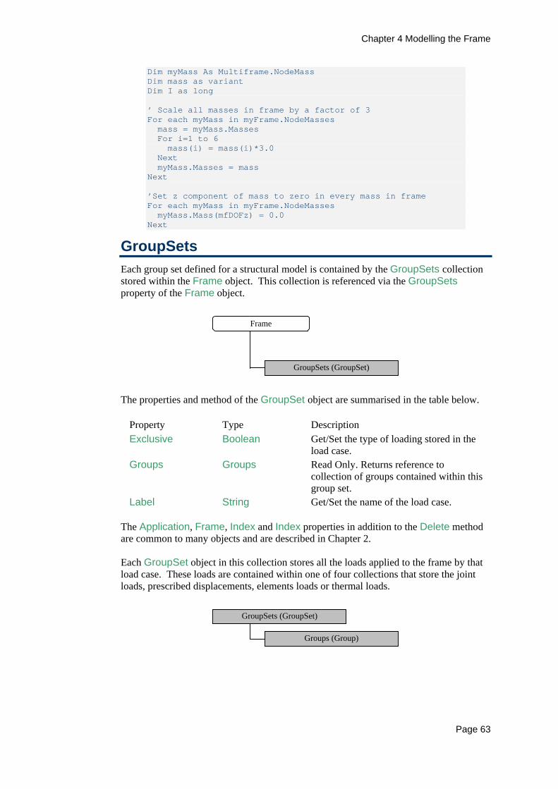
Chapter 4 Modelling the Frame
Page 63
Dim myMass As Multiframe.NodeMass Dim mass as variant Dim I as long ’ Scale all masses in frame by a factor of 3 For each myMass in myFrame.NodeMasses mass = myMass.Masses For i=1 to 6 mass(i) = mass(i)*3.0 Next myMass.Masses = mass Next ’Set z component of mass to zero in every mass in frame For each myMass in myFrame.NodeMasses myMass.Mass(mfDOFz) = 0.0 Next
GroupSets Each group set defined for a structural model is contained by the GroupSets collection stored within the Frame object. This collection is referenced via the GroupSets property of the Frame object.
Frame
GroupSets (GroupSet)
The properties and method of the GroupSet object are summarised in the table below.
Property Type Description Exclusive Boolean Get/Set the type of loading stored in the
load case. Groups Groups Read Only. Returns reference to
collection of groups contained within this group set.
Label String Get/Set the name of the load case. The Application, Frame, Index and Index properties in addition to the Delete method are common to many objects and are described in Chapter 2. Each GroupSet object in this collection stores all the loads applied to the frame by that load case. These loads are contained within one of four collections that store the joint loads, prescribed displacements, elements loads or thermal loads.
GroupSets (GroupSet)
Groups (Group)
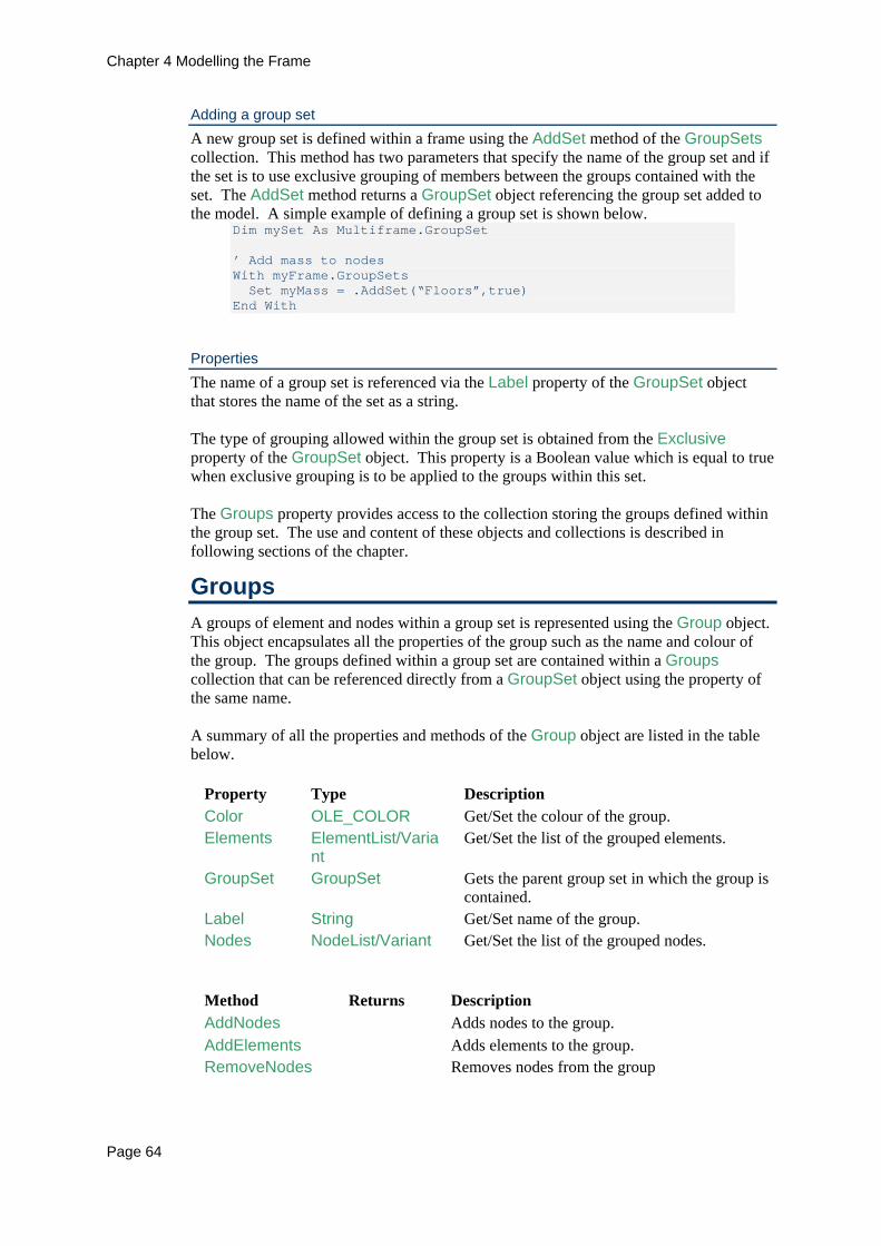
Chapter 4 Modelling the Frame
Page 64
Adding a group set A new group set is defined within a frame using the AddSet method of the GroupSets collection. This method has two parameters that specify the name of the group set and if the set is to use exclusive grouping of members between the groups contained with the set. The AddSet method returns a GroupSet object referencing the group set added to the model. A simple example of defining a group set is shown below.
Dim mySet As Multiframe.GroupSet ’ Add mass to nodes With myFrame.GroupSets Set myMass = .AddSet(“Floors”,true) End With
Properties The name of a group set is referenced via the Label property of the GroupSet object that stores the name of the set as a string. The type of grouping allowed within the group set is obtained from the Exclusive property of the GroupSet object. This property is a Boolean value which is equal to true when exclusive grouping is to be applied to the groups within this set. The Groups property provides access to the collection storing the groups defined within the group set. The use and content of these objects and collections is described in following sections of the chapter.
Groups A groups of element and nodes within a group set is represented using the Group object. This object encapsulates all the properties of the group such as the name and colour of the group. The groups defined within a group set are contained within a Groups collection that can be referenced directly from a GroupSet object using the property of the same name. A summary of all the properties and methods of the Group object are listed in the table below.
Property Type Description Color OLE_COLOR Get/Set the colour of the group. Elements ElementList/Varia
nt Get/Set the list of the grouped elements.
GroupSet GroupSet Gets the parent group set in which the group is contained.
Label String Get/Set name of the group. Nodes NodeList/Variant Get/Set the list of the grouped nodes.
Method Returns Description AddNodes Adds nodes to the group. AddElements Adds elements to the group. RemoveNodes Removes nodes from the group

Chapter 4 Modelling the Frame
Page 65
Method Returns Description RemoveElements
Removes element from the group
In addition, the Application, Frame, Number and Index properties as well as the Delete method are common to many objects and are described in Chapter 2.
Creating a Group A new group is added to a group set using the AddGroup method of the Groups collection. This method accepts three parameters that specify the name of the group, the grouped nodes and the grouped elements. The nodes and elements in the group are specified using a variant parameter and so any value representing a group of nodes or group of elements can be used to specify these lists. Typically this will be either an array of indices or a list object or can be omitted if the group is to be created with no content. The AddGroup method returns the Group object referencing the new group added to the frame. The following code demonstrates how to add a group to the frame. In this example, elements 1 to 5 are grouped together to
Dim myGroup As Multiframe.Group ’ Create the group in the floors group set With myFrame.GroupSets(“Floors”) Set myGroup = .AddGroup("Floor 1", ,“1-5”) End With
Properties The Nodes property of the Group object returns a NodeList object containing each of the nodes in the group. This property can also be used to set the nodes in the group and can be set equal to any value that represents one or more nodes such as a NodeList object.
Dim myNodeList As New Multiframe.NodeList ' Find all nodes in second floor which is at y=6.5 Set myNodeList = myFrame.Nodes.Find("y", 6.4, 6.6) With myFrame.GroupSets(“Floors”) ’ Reset nodes in the group .Group(”Floor 1”).Nodes = myNodeList ’ Reset elements in the group .Group(”Floor 1”).Elements = “1-6” End With
Similarly, the Elements property of the Group object returns a ElementList object containing each of the elements in the group. This property can also be used to set the elements in the group and can be set equal to any value that represents one or more elements such as a ElementList object.
With myFrame.GroupSets(“Floors”) ’ Reset elements in the group .Group(”Floor 1”).Elements = “1-6” End With
The colour of a group is referenced via the Color property of the Group object. The property is of type OLE_COLOR.

Chapter 4 Modelling the Frame
Page 66
With myFrame.GroupSets(“Floors”) .Group(”Floor 1”).Colour = 255 ‘red .Group(”Floor 2”).Colour = 16711680 ‘blue .Group(”Floor 3”).Colour = 65280 ‘green End With
The name of the group is referenced via the Label property of the Group object.
OLE_COLOR The OLE_COLOR data type represents a colour as a BGR (Blue, Green, Red) value. The OLE_COLOR value of a colour specified by its red, green and blue components (each of which has a value from 0 - 255) is determined using the following expression: OLE_COLOR value = red + (green * 256) + (blue * 65536)
The OLE_COLOUR values of some common colours are as follows:
Black 0
Dark Grey 4210752
Grey 8421504
Light Grey 12632256
White 16777215
Red 255
Green 65280
Blue 16711680
Magenta 16711935
Cyan 16776960
Methods Nodes may be added or removed from the group using the AddNodes and RemoveNodes methods of the Group object. These methods take a single variant parameter that specifies the nodes to be added or removed from the group. A simple example demonstrating the various parameters that can be passed to these methods is shown below.
Dim mylist As New Multiframe.NodeList mylist.Add "20-30"

Chapter 4 Modelling the Frame
Page 67
With mfApp.Frame.GroupSets(“Floors”).Group(1) ’Add nodes to linked group Call .AddNodes(1) 'Add node by index Call .AddNodes("2-9,12") 'Add nodes listed by index Call .AddNodes(mfApp.Frame.Nodes(10)) 'Add node using node object Call .AddNodes(mylist) 'Add nodes using list ‘Remove nodes from linked group Call .RemoveNodes(1) 'By index Call .RemoveNodes("2-9,12") Call .RemoveNodes(mylist) 'Using a list of nodes End With
The manipulation of elements in a group in handled in a similar manner. Elements may be added or removed from the group using the AddElements and RemoveElements methods of the Group object. These methods take a single variant parameter that specifies the elements to be added or removed from the group. A simple example demonstrating the various parameters that can be passed to these methods is shown below.
Dim mylist As New Multiframe.ElementList mylist.Add "20-30" With mfApp.Frame.GroupSets(“Floors”).Group(“Floor 1”) ’Add Elements to linked group Call .AddElements(1) 'Add Element by index Call .AddElements("2-9,12") 'Add Elements listed by index Call .AddElements(mylist) 'Add Elements using list ‘Remove Elements from linked group Call .RemoveElements(1) 'By index Call .RemoveElements("2-9,12") Call .RemoveElements(mylist) 'Using a list of elements End With
Members The Member object represents a design member within a structure. This object encapsulates all the properties of a design member such as its position, length, slope, section and orientation. All the members that are defined within a structure are contained within the Members collection that is stored as part of the Frame object.
Frame
Members (Member)
A summary of all the properties and methods of the Member object are listed in the table below.
Properties Type Description Elements ElementList Get the list of elements that make
up the member.

Chapter 4 Modelling the Frame
Page 68
Properties Type Description FlipSectionXX Boolean Get/Set whether the members
section is flipped about its x-axis. FlipSectionYY Boolean Get/Set whether the members
section is flipped about its y-axis. Length Double Read Only. Returns the length of
the member. Node* Node/Variant Read Only. Returns the node at a
specified end of the member. Nodes NodeList Read Only. Returns a list of all
nodes along the member. Orientation Double Get/Set the orientation of the
member. Section Section/Variant Get/Set the section. Slope Double Read Only. Get the slope of the
member. SlopeXY Double Read Only. Get the slope of the
member in the X-Y plane. SlopeZX Double Read Only. Get the slope of the
member in the Z-X plane. SlopeZY Double Read Only. Get the slope of the
member in the Z-Y plane. XYZ* Variant Read only. Returns the position of
a specified end of the member. X* Double Read only. Returns the x-
coordinate of a specified end of the member.
Y* Double Read only. Returns the y-coordinate of a specified end of the member.
Z* Double Read only. Returns the z-coordinate of a specified end of the member.
*Denotes a property that takes a parameter specifying an end of the member.
Method Returns Description GlobalToLocal
Variant Transforms a vector of values from global to local member coordinates.
LocalToGlobal
Variant Transforms a vector of values from local member coordinates to global coordinates.
Results MemberResult Returns the results at the member for a specific analysis and load case.
SetSection Sets the section type of the member. Ungroup Ungroups the elements forming the design
member. In addition, the Application, Frame, Number, Label and Index properties as well as the Delete method are common to many objects and are described in Chapter 2.

Chapter 4 Modelling the Frame
Page 69
Creating Members A design member in Multiframe is a single element or a group of collinear connected elements. Elements can be grouped together to form a design member using the Group method of the Members object. This method requires a single parameter that specifies the elements to be linked together. This is a variant parameter and so any value identifying a list of elements will be acceptable such as an array of elements indices or an ElementList object. A simple example demonstrating this method is shown below. This example subdivides an element and then groups the resulting elements into a single member.
Dim myElList As New Multiframe.ElementList Dim myMbr As Multiframe.Member ’ Subdivide element Set myElList = myFrame.Elements(1).Subdivide(5) ’Create design member from new elements forming the original element Call myFrame.Members.Group(myElList)
Properties The section and its orientation within a member are referenced via the Section, Orientation, FlipSectionXX, FlipSectionYY properties of the Member object. The Section property identifies the Section object that represents the section currently allocated to the member. When setting the Section property, the new section can be specified using a Section object or by its name. In this case, Multiframe will search the section library to locate a matching section. Additional functionality for setting the section type is provided by the SetSection method described in the next section. The orientation of the section, expressed in the current angle units, is controlled via the Orientation property. For sections that are not double symmetric, the orientation method is complemented by the FlipSectionXX, FlipSectionYY properties that provide a means of correctly positioning the section in relation to the member. When these properties are set true, the orientation of the section will be flipped about the specified axis. An example on setting the section type and orientation is shown below.
Dim myMbr as Multiframe.Member Dim s as string ’Get reference to member 12 Set myMbr = myFrame.Members(12) ’Set section type using two different methods myMbr.Section = mfApp.SectionsLibrary.Groups(1).Sections(3) myMbr.Section = “610UB101” ’Set section orientation myMbr.Orientation= 45.0 myMbr.FlipSectionXX = true myMbr.FlipSectionYY = false ’Notify user of elements section type s = "Member "+Str(myMbr.Index)+” has section type ”+myMbr.Section.Name MsgBox s, vbOKOnly, "Multiframe"
The position of a members end can be determined using the X, Y and Z properties of the Member object which each return a single component of the ends position in global coordinates. The XYZ property provides a faster method of accessing all three components of an end position and returns the coordinates as array of three values. Each of the methods takes a single parameter identifying an end of the member.

Chapter 4 Modelling the Frame
Page 70
The length and slope of a member can be determined from the read-only properties Length, Slope, SlopeXY, SlopeZX, SlopeZY. The Length property returns the length of the member in the current length units. Note the length of the member is measured between end points defined by the end offsets and is NOT the distance between the nodes defining the member. The four methods for returning the slope of the member return a value in terms of the current angular units set within Multiframe. The Slope method returns the slope of the member in the X-Y plane and corresponds the slope of the member displayed in the user interface. The other three slope methods return the slope of the member in a specific plane. The SlopeXY returns the slope of the member in the XY plane that is measured from the X to the Y-axes. Similar the SlopeZX and SlopeZY properties return the slope of the member in the ZX and ZY plane respectively, with the angle measured from the Z axis.
Dim myMbr as Multiframe.Member Dim s as string ’Get reference to member 10 Set myMbr = myFrame.Members(10) ’Notify user of members slope in XY plane s = "Slope of Member in XY plane is: "+Str(myMbr.SlopeXY) MsgBox s, vbOKOnly, "Member "+Str(myMbr.Index) ’Notify user of members slope in ZX plane s = "Slope of Member in ZX plane is: "+Str(myMbr.SlopeZX) MsgBox s, vbOKOnly, "Member "+Str(myMbr.Index)
The elements that form a design member are referenced via the Elements property of the Member object. This property returns an ElementList object that contains each of the elements forming the member. Similarly, the Nodes property of the Member object returns a list of all the nodes along the member.
Methods The SetSection method of the Member object is used to specify the section type of a member. This method takes up to two parameters that specify the section and optionally the group in which it is contained. The section can be identified in a number of ways; the first is simply by the index of the section and the group in which it is contained. In this case the group can be specified by its index within the sections library, its name or by passing a SectionGroup object. The second method of setting the section is to use its name. In this case no group is required and Multiframe will search the entire sections library to locate the sections. The final way of setting the section type is to pass a Section object. Some typical uses of this method are shown in the following code.
Dim myMbr As Multiframe.Member Dim mySection as Multiframe.Section ’Get reference to member 5 Set myMbr = myFrame.Members(5) 'Set section to the fourth section in the second group Call myMbr.SetSection(4,2) 'Set section to sixth section in the group named UB Call myMbr.SetSection(6,”UB”) 'Set section to section named 610UB101 Call myMbr.SetSection(“610UB101”) 'Set section to fifth section in fourth group using section object Set mySection = mfApp.SectionsLibrary.groups(4).Sections(5) Call myMbr.SetSection(mySection)
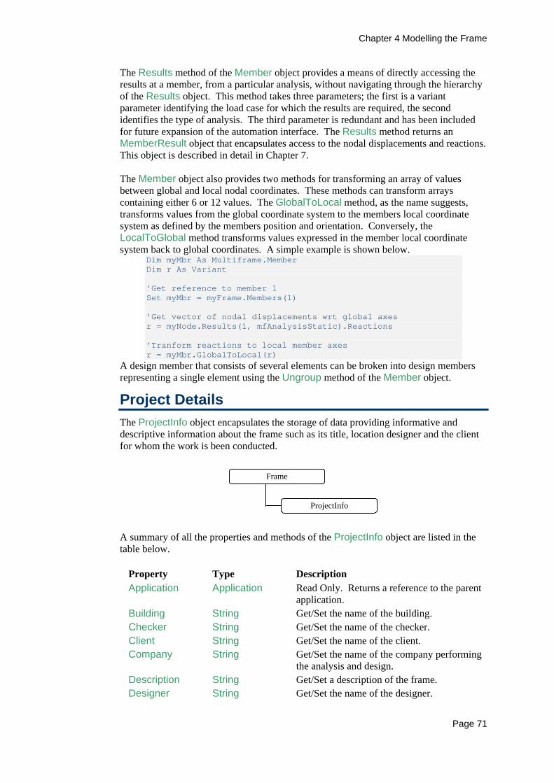
Chapter 4 Modelling the Frame
Page 71
The Results method of the Member object provides a means of directly accessing the results at a member, from a particular analysis, without navigating through the hierarchy of the Results object. This method takes three parameters; the first is a variant parameter identifying the load case for which the results are required, the second identifies the type of analysis. The third parameter is redundant and has been included for future expansion of the automation interface. The Results method returns an MemberResult object that encapsulates access to the nodal displacements and reactions. This object is described in detail in Chapter 7. The Member object also provides two methods for transforming an array of values between global and local nodal coordinates. These methods can transform arrays containing either 6 or 12 values. The GlobalToLocal method, as the name suggests, transforms values from the global coordinate system to the members local coordinate system as defined by the members position and orientation. Conversely, the LocalToGlobal method transforms values expressed in the member local coordinate system back to global coordinates. A simple example is shown below.
Dim myMbr As Multiframe.Member Dim r As Variant ’Get reference to member 1 Set myMbr = myFrame.Members(1) ’Get vector of nodal displacements wrt global axes r = myNode.Results(1, mfAnalysisStatic).Reactions ’Tranform reactions to local member axes r = myMbr.GlobalToLocal(r)
A design member that consists of several elements can be broken into design members representing a single element using the Ungroup method of the Member object.
Project Details The ProjectInfo object encapsulates the storage of data providing informative and descriptive information about the frame such as its title, location designer and the client for whom the work is been conducted.
Frame
ProjectInfo
A summary of all the properties and methods of the ProjectInfo object are listed in the table below.
Property Type Description Application Application Read Only. Returns a reference to the parent
application. Building String Get/Set the name of the building. Checker String Get/Set the name of the checker. Client String Get/Set the name of the client. Company String Get/Set the name of the company performing
the analysis and design. Description String Get/Set a description of the frame. Designer String Get/Set the name of the designer.

Chapter 4 Modelling the Frame
Page 72
Property Type Description Frame String Read Only. Returns a reference to the parent
frame object. JobID String Get/Set the ID of the job. Keywords String Get/Set keywords describing the frame. LastModifiedBy
String Read Only. Returns the user name of who last modified the file.
Notes String Get/Set any notes about the frame. Revision Long Read Only. Revision of the frame. Site String Get/Set the name of the site. Title String Get/Set the title of the frame. Version String Get/Set the user definable version of the
frame.
Properties Most of the properties of the ProjectInfo object are user definable fields describing the project and the people/organisations involved in the project. A simple example of how to modify the project details is shown below.
With myFrame.ProjectInfo .Company = "John Smith Design" .Designer = "John Smith" .Checker = "John Smith Jr" .Title = "My Steel Building" .JobID = "2001/196" End With
Improving performance with lists To improve the speed of your scripts, more than a single node or element can be added to the frame at a time using the AddNodes and AddElements methods of the Nodes and Elements collections. These methods can take arrays of parameters describing each of the items to be added to the frame and return a list of the items added to the frame. For example, the two nodes could be created with a single call to the Multiframe application as follows
Dim myNodeList as New Multiframe.NodeList With mfFrame.Nodes Set myNodeList = .AddNodes(Array(0.0,5.0),Array(2.5,5.0),0) End With
or Dim objNodeList as New Multiframe.NodeList Dim xArray(1 to 2) as double Dim yArray(1 to 2) as double Set objNodeList = myFrame.Nodes.AddNodes(xArray,yArray,0.0)
The first two parameters specify the x and y coordinates of the two nodes that will be added to the frame. Note that the third parameter contains only a single scalar value for the z coordinate; this value will be applied to all nodes added to the frame. A further benefit of using lists is that the properties of the items can be set much more readily. For example, if all the nodes added by the above code were to be pinned, then this could be done using the line of code
myNodeList.Pinned = true
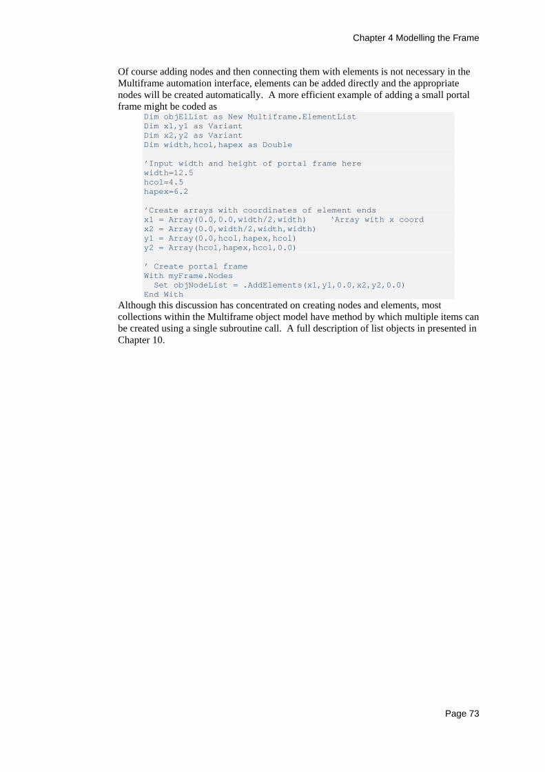
Chapter 4 Modelling the Frame
Page 73
Of course adding nodes and then connecting them with elements is not necessary in the Multiframe automation interface, elements can be added directly and the appropriate nodes will be created automatically. A more efficient example of adding a small portal frame might be coded as
Dim objElList as New Multiframe.ElementList Dim x1,y1 as Variant Dim x2,y2 as Variant Dim width,hcol,hapex as Double ’Input width and height of portal frame here width=12.5 hcol=4.5 hapex=6.2 ’Create arrays with coordinates of element ends x1 = Array(0.0,0.0,width/2,width) ‘Array with x coord x2 = Array(0.0,width/2,width,width) y1 = Array(0.0,hcol,hapex,hcol) y2 = Array(hcol,hapex,hcol,0.0) ’ Create portal frame With myFrame.Nodes Set objNodeList = .AddElements(x1,y1,0.0,x2,y2,0.0) End With
Although this discussion has concentrated on creating nodes and elements, most collections within the Multiframe object model have method by which multiple items can be created using a single subroutine call. A full description of list objects in presented in Chapter 10.


Chapter 5 The Load Objects
Page 75
Chapter 5 The Load Objects This chapter describes the object hierarchy used to describe the loads applied to the structure. This includes the objects and collections describing the individual loads applied to nodes and elements as well as the load cases into which the loads are grouped.
Load Cases Each load case applied to a structural model is contained by the LoadCases collection stored within the Frame object. This collection is referenced via the LoadCases property of the Frame object. Alternatively, this collection can be accessed directly from the Multiframe Application object via its LoadCases property. The properties and method of the LoadCase object are summarised in the table below.
Property Type Description Acceleration Double Get/Set component of acceleration.
(Self weight load cases only) Accelerations Variant Get/Set vector of accelerations.
(Self weight load cases only) ElementLoads ElementLoads Read Only. Returns reference to
collection of element loads contained within this load case.
Factor Double Get/Set factor for particular load case. (Combined load cases only)
Factors Variant Get/Set load case factors. (Combined load cases only)
LoadType mfLoadType Get/Set the type of loading stored in the load case.
Name String Get/Set the name of the load case. NodeLoads NodeLoads Read Only. Returns reference to
collection of nodal loads contained within this load case.
PrescribedDisps NodePreDisps Read Only. Returns reference to collection of prescribed displacements contained within this load case.
ThermalLoads ThermalLoads Read Only. Returns reference to collection of thermal loads contained within this load case.
Type mfLoadCaseType
Get/Set the type of load case.
The Application, Frame, Index and Index properties in addition to the Delete method are common to many objects and are described in Chapter 2. Load cases are categorized as static, combined or self-weight. While each of these is defined by slightly different information, the LoadCase object is used to describe all three types of cases. The type of a load case is defined when it is created and cannot be changed. If the user accesses a property of the LoadCase object that is not relevant to the type of the load case, an error will be returned.
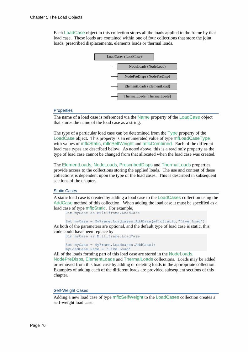
Chapter 5 The Load Objects
Page 76
Each LoadCase object in this collection stores all the loads applied to the frame by that load case. These loads are contained within one of four collections that store the joint loads, prescribed displacements, elements loads or thermal loads.
LoadCases (LoadCase)
NodeLoads (NodeLoad)
ElementLoads (ElementLoad)
NodePreDisps (NodePreDisp)
ThermalLoads (ThermalLoads)
Properties The name of a load case is referenced via the Name property of the LoadCase object that stores the name of the load case as a string. The type of a particular load case can be determined from the Type property of the LoadCase object. This property is an enumerated value of type mfLoadCaseType with values of mflcStatic, mflcSelfWeight and mflcCombined. Each of the different load case types are described below. As noted above, this is a read only property as the type of load case cannot be changed from that allocated when the load case was created. The ElementLoads, NodeLoads, PrescribedDisps and ThermalLoads properties provide access to the collections storing the applied loads. The use and content of these collections is dependent upon the type of the load cases. This is described in subsequent sections of the chapter.
Static Cases A static load case is created by adding a load case to the LoadCases collection using the AddCase method of this collection. When adding the load case it must be specified as a load case of type mflcStatic. For example,
Dim myCase as Multiframe.LoadCase Set myCase = MyFrame.Loadcases.AddCase(mflcStatic,”Live Load”)
As both of the parameters are optional, and the default type of load case is static, this code could have been replace by
Dim myCase as Multiframe.LoadCase Set myCase = MyFrame.Loadcases.AddCase() myLoadCase.Name = “Live Load”
All of the loads forming part of this load case are stored in the NodeLoads, NodePreDisps, ElementLoads and ThermalLoads collections. Loads may be added or removed from this load case by adding or deleting loads in the appropriate collection. Examples of adding each of the different loads are provided subsequent sections of this chapter.
Self-Weight Cases Adding a new load case of type mflcSelfWeight to the LoadCases collection creates a self-weight load case.

Chapter 5 The Load Objects
Page 77
Dim myCase as Multiframe.LoadCase Set myCase = myFrame.Loadcases.AddCase(mflcSelfWeight,”Self Weight”)
A self-weight load cases is defined by the accelerations applied in each of the global directions. These values may be accessed via either the Acceleration or Accelerations properties. The Acceleration property takes a single parameter identifying the global direction and provides access to each of the individual components. For example
Dim accel as Double ‘Setting accelerations myLoadCase.Acceleration(1) = 0.0 ‘Set x-component myLoadCase.Acceleration(mfDOFy) = 0.0 ‘Set x-component ’ Accessing loadcase factors accel = myLoadCase.Acceleration(3) ‘Get z-component
Alternatively the accelerations may be accessed via the Accelerations property which is a variant property containing an array of 3 doubles, each value representing a component of the acceleration.
Dim myAccels as Variant ’Set components of acceleration myFrame.LoadCases(4).Accelerations = Array(0.0,-9.81,0.0) ’Get acceleration components myAccels = myFrame.LoadCases(4).Accelerations
The ElementLoads collection of a self-weight load case contains the distributed loads representing the self-weight of each element in the frame to which the self-weight is applied. This collection is managed by the Multiframe application and is automatically updated as the structure is changed. As such, loads cannot be added or removed from this collection. In fact, no loads may be added to the other loading collections in this type of load case and these will always remain empty.
Combined Cases Adding a new LoadCase object of type mflcCombined to the LoadCases collection creates a combined or factored load case.
Dim myLoadCase as Multiframe.LoadCase Set myLoadCase = MyFrame.Loadcases.AddCase(mflcCombined,”DL + LL”)
The factors for each of the static or self-weight load cases that are combined to define this load case are specified using the Factor property of the LoadCase object. This property takes a single variant parameter that identifies the load case to which the factor is to be applied. This variant may be either the index of the load case, the name of the load case or even another LoadCase object as demonstrated below
Dim factor as Double ’ Setting loadcase factors myLoadCase.Factor(2) = 0.8 ‘By index myLoadCase.Factor(“Live Load”) = 1.5 ‘By name myLoadCase.Factor(myFrame.LoadCases(2)) = 1.5 ‘By LoadCase object ’ Accessing loadcase factors factor = myLoadCase.Factor(2) ‘ By index factor = myLoadCase.Factor(“Live Load”) ‘ By name factor = myLoadCase.Factor(myFrame.LoadCases(2)) ‘ By object

Chapter 5 The Load Objects
Page 78
The load case factors may also be accessed via the Factors property of the LoadCase object. This variant property returns an array of values representing the factors applied to each load case contained within the frame. For example;
Dim myFactors as Variant myFactors = myFrame.LoadCases(4).Factors ‘Get factors myFrame.LoadCases(4).Factors = Array(1.0,1.0,1.5) ‘Set factors
The NodeLoads, NodePreDisps, ElementLoads and ThermalLoads collections of a combined load case contain the factored loads from each of the load cases contributing to the combined case. These collections are maintained by the Multiframe application with loads been automatically updated when loading in one of the base load cases is changed. As such, loads cannot be added or removed from these collections.
Node Loads A NodeLoad object represents a force or moment load applied to a node within the structure. All the nodal loads applied in a particular load case are stored in a NodeLoads collection. These loads can be accessed via the NodeLoads property of the LoadCase object. The properties and methods of the Node object are listed below.
Property Type Description DOF mfDOF Get/Set the degree of freedom identifying the
direction in which the load is applied. Global Boolean Get/Set whether the load is applied in global or
local axes. Kind String Set/Get the direction and axes in which the load
is applied. LoadCase LoadCase Read Only. Returns a reference to the load case
in which the load is applied. Node Node/Variant Get/Set the node to which the load is applied. Value Double Get/Set the magnitude of the load.
The Application, Frame, Number, Label and Index properties as well as the Delete method are common to many objects and are described in Chapter 2.
Creating a Node Load A nodal force loading is added to a load case using the AddLoad method of the NodeLoads collection. The first parameter of this method accepts a variant value that specifies the node at which the load is to be applied. This parameter may specify the node by either its integer index or by using a Node object. The next two parameters are optional and specify the direction of the load and it’s magnitude, which is set using the current force or moment units set within the Multiframe application. The AddLoad method returns a NodeLoad object that references the new load added to the structure. For example, the following demonstrates how to add node loads to a structure.

Chapter 5 The Load Objects
Page 79
Dim myLoad as Multiframe.NodeLoad With myFrame.LoadCases(1) ’Add load of magnitude 10.5 units to node 12 in the x direction set myLoad = .NodeLoads.AddLoad(12,mfDOFx,10.5) ’Add load of magnitude 4.5 units to node 7 in the y direction set myLoad =.NodeLoads.AddLoad(myFrame.Nodes(7),2,4.5) End With
The AddLoad method can also take an extra optional parameter that specifies if the load is to be applied in the global or the local nodal coordinate system. By default, all node loads are added in the local nodal coordinate system. Groups of nodal forces can be created using the AddLoads method of the NodeLoads collection. This method returns a NodeLoadList containing each of the loads added to the frame. The parameters of this method correspond to the parameters of the AddLoad method except that each parameter may be either an array, containing values for each of the new loads, or a single value that will be applied to each of the new loads. Several examples of how this method may be used are as follows:
Dim myLoads as New Multiframe.NodeLoadList Dim myNodeLoads as Multiframe.NodeLoads Dim myVar as Variant ’Get reference to node loads collection set myNodeLoads = myFrame.LoadCases(1).NodeLoads ’Add a single load set myLoads = myNodeLoads.AddLoads(12,mfDOFx,10.5) ’Add the same load at nodes 1,2 and 5 set myLoads = myNodeLoads.AddLoads(Array(1,2,5),mfDOFx,10.5) ’Add two loads at node 12 myVar=Array(mfDOFx, mfDOFy) set myLoads = myNodeLoads.AddLoads(12,myVar,Array(7.5,5.5)) ’Add two loads set myLoads = myNodeLoads.AddLoads(Array(4,5),myVar,Array(7.5,5.5)) ’Add a single load to each node in frame set myLoads = myNodeLoads.AddLoads(myFrame.Nodes,mfDOFx,2.75)
The first parameter of the AddLoads method is a variant parameter identifying the nodes to which the loads are to be applied. This parameter may specify the nodes by an integer index, an array of integer indices, a Node object, a NodeList, or a Nodes collection.
NodeLoad Properties A nodal load can be modified via the NodeLoad object. This object has properties describing the node to which the load is applied, the direction, magnitude and the axis to which the loading is orientated. The node at which the load is applied is identified by the Node property of the NodeLoad object. This property returns the Node object corresponding the node at which the load is applied. This property may be set to a new value using any variant value representing a node.
Chapter 5 The Load Objects
Page 80
The DOF property controls the direction in which the load is applied. The property is an enumerated value of type mfDOF. Nodal force loads are applied with a DOF set to mfDOFx, mfDOFy or mfDOFz that describes the direction in which the load is applied. Nodal moment loads are specified with a DOF of mfDOFthetax, mfDOFthetay or mfDOFthetaz. The axes to which these degrees of freedom refer are specified by the Global property. If this Boolean property is true then the load is applied in the direction of the global coordinate axes. If the Global property is false, the load is directed along the local nodal axes that are specified by the nodal orientation. The direction and axes of the loading may also be specified using the Kind property. This property is a character string describing the direction of loading and the axes to which the load is applied. The magnitude of the load is stored in the Value property of the NodeLoad object. The value of this property describes the magnitude in terms of the force or moment units currently set within the Multiframe application. An example of how these properties may be changed is as follows
Dim myLoad as Multiframe.NodeLoad ’Get reference to node load set myLoad = myFrame.LoadCases(1).NodeLoads(4) ’Change load to 10.5 unit load applied in global z direction myLoad.DOF = mfDOFz myLoad.Value = 10.5 myLoad.Global = true ’Change direction such that load applied in local x direction myLoad.Kind = ”Px’”
Prescribed Displacements The NodePreDisp object represents a prescribed displacement applied to a node as part of a load case. All the prescribed displacements applied in a particular load case are stored in a NodePreDisps collection. These displacements can be accessed via the PrescribedDisps property of the LoadCase object. The NodePreDisp object is identical to the NodeLoad object except that the Value property of the NodePreDisp object returns a displacement or rotation instead of a force or a moment. The value of the displacement is specified in the current displacement or angular displacement units. Similarly, new displacements are added to a load case using the AddDisp or AddDisps methods of the NodePreDisps collection and these methods have the same syntax as the AddLoad and AddLoads methods of the NodeLoads collection. For example, the following code adds two prescribed displacements to the first load case.
Dim myLoad as Multiframe.NodePreDisp Dim myNode as Multiframe.Node With myFrame.LoadCases(1) ’Add prescribed displacement of magnitude 7.5 units to node 12 set myLoad = .PrescribedDisps.AddDisp(12,mfDOFx,7.5) ’Add prescribed rotation of magnitude 0.5 about the z-axis to node 7 set myNode = myFrame.Nodes(7) set myLoad = .PrescribedDisps.AddDisp(myNode,6,0.5) End With
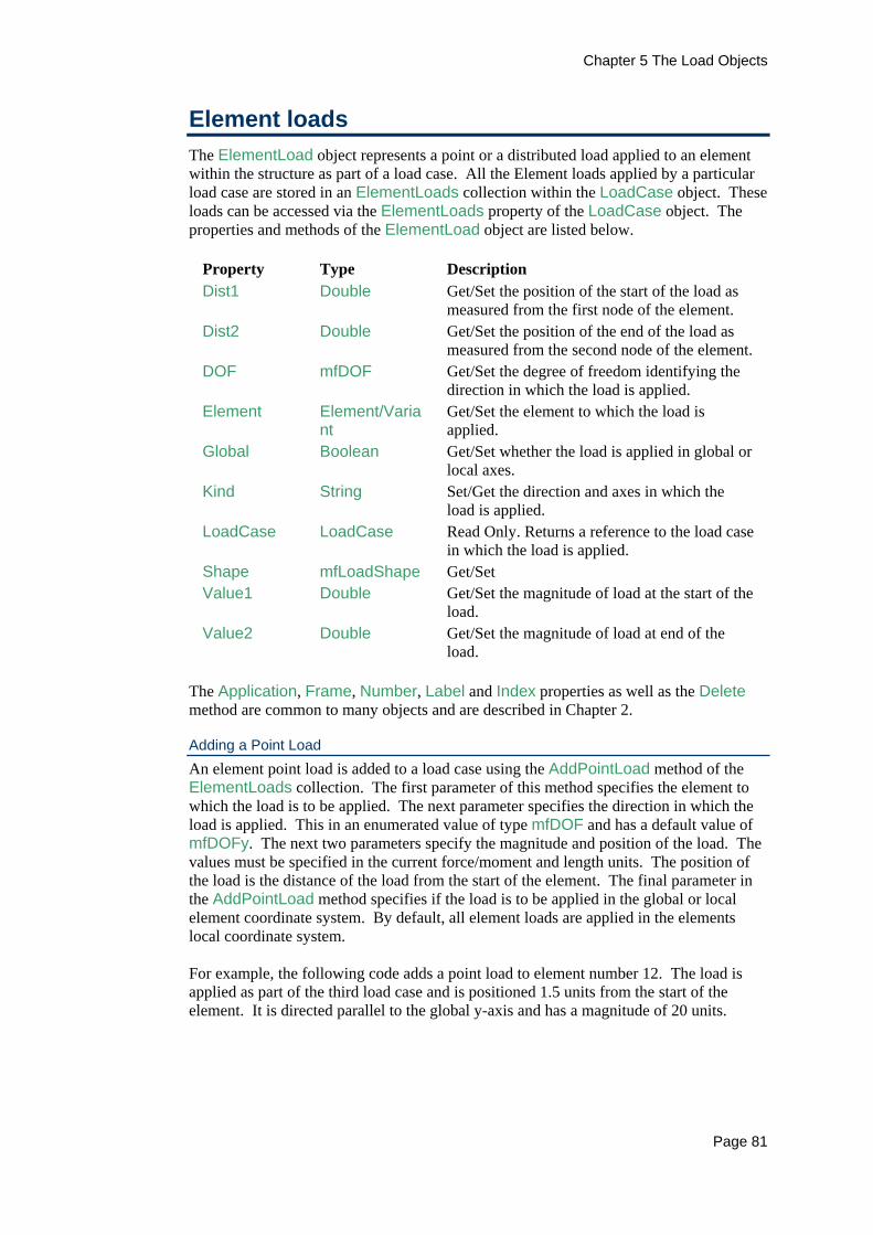
Chapter 5 The Load Objects
Page 81
Element loads The ElementLoad object represents a point or a distributed load applied to an element within the structure as part of a load case. All the Element loads applied by a particular load case are stored in an ElementLoads collection within the LoadCase object. These loads can be accessed via the ElementLoads property of the LoadCase object. The properties and methods of the ElementLoad object are listed below.
Property Type Description Dist1 Double Get/Set the position of the start of the load as
measured from the first node of the element. Dist2 Double Get/Set the position of the end of the load as
measured from the second node of the element. DOF mfDOF Get/Set the degree of freedom identifying the
direction in which the load is applied. Element Element/Varia
nt Get/Set the element to which the load is applied.
Global Boolean Get/Set whether the load is applied in global or local axes.
Kind String Set/Get the direction and axes in which the load is applied.
LoadCase LoadCase Read Only. Returns a reference to the load case in which the load is applied.
Shape mfLoadShape Get/Set Value1 Double Get/Set the magnitude of load at the start of the
load. Value2 Double Get/Set the magnitude of load at end of the
load. The Application, Frame, Number, Label and Index properties as well as the Delete method are common to many objects and are described in Chapter 2.
Adding a Point Load An element point load is added to a load case using the AddPointLoad method of the ElementLoads collection. The first parameter of this method specifies the element to which the load is to be applied. The next parameter specifies the direction in which the load is applied. This in an enumerated value of type mfDOF and has a default value of mfDOFy. The next two parameters specify the magnitude and position of the load. The values must be specified in the current force/moment and length units. The position of the load is the distance of the load from the start of the element. The final parameter in the AddPointLoad method specifies if the load is to be applied in the global or local element coordinate system. By default, all element loads are applied in the elements local coordinate system. For example, the following code adds a point load to element number 12. The load is applied as part of the third load case and is positioned 1.5 units from the start of the element. It is directed parallel to the global y-axis and has a magnitude of 20 units.
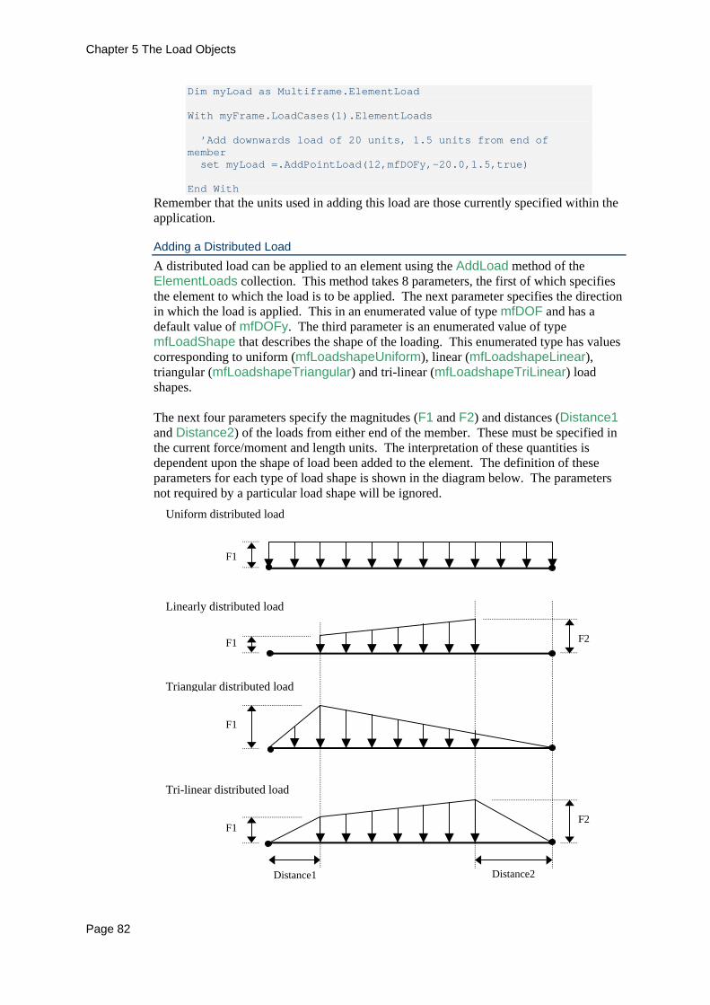
Chapter 5 The Load Objects
Page 82
Dim myLoad as Multiframe.ElementLoad With myFrame.LoadCases(1).ElementLoads ’Add downwards load of 20 units, 1.5 units from end of member set myLoad =.AddPointLoad(12,mfDOFy,-20.0,1.5,true) End With
Remember that the units used in adding this load are those currently specified within the application.
Adding a Distributed Load A distributed load can be applied to an element using the AddLoad method of the ElementLoads collection. This method takes 8 parameters, the first of which specifies the element to which the load is to be applied. The next parameter specifies the direction in which the load is applied. This in an enumerated value of type mfDOF and has a default value of mfDOFy. The third parameter is an enumerated value of type mfLoadShape that describes the shape of the loading. This enumerated type has values corresponding to uniform (mfLoadshapeUniform), linear (mfLoadshapeLinear), triangular (mfLoadshapeTriangular) and tri-linear (mfLoadshapeTriLinear) load shapes. The next four parameters specify the magnitudes (F1 and F2) and distances (Distance1 and Distance2) of the loads from either end of the member. These must be specified in the current force/moment and length units. The interpretation of these quantities is dependent upon the shape of load been added to the element. The definition of these parameters for each type of load shape is shown in the diagram below. The parameters not required by a particular load shape will be ignored.
F2
F2
F1
F1
F1
Distance2 Distance1
F1
Uniform distributed load
Linearly distributed load
Triangular distributed load
Tri-linear distributed load
Chapter 5 The Load Objects
Page 83
The final parameter of the AddLoad method specifies if the load is to be applied in the global or local element coordinate system. By default, all element loads are applied in the elements local coordinate system. The small script shown below demonstrates how the AddLoad method may be used to add the different types of loads.
Dim myLoad as Multiframe.ElementLoad Dim myElLoads as Multiframe.ElementLoads Dim L as double ’Get reference to element loads collection set myElLoads = myFrame.LoadCases(1).ElementLoads With myElLoads ’Add uniformly distributed load set myLoad =.AddLoad(12,mfDOFy,mfLoadshapeUniform,1.5,bGlobal:=true) ’Add linearly varying distributed load set myLoad =.AddLoad(12,3,mfLoadshapeLinear,1.5,0.5,2.5,0.5) ’Add triangular load L = myFrame.Elements(5).Length set myLoad =.AddLoad(5,2,mfLoadshapeTriangular,1.5,0.5*L,true) ’Add tri-linear load set myLoad=.AddLoad(5,2,mfLoadshapeTriLinear,1.5,0.3*L,1.5,0.3*L) End With
The AddLoad method can also be used to add a point load to an element by specifying the shape of the load as mfLoadshapePoint. In this case, the magnitude is specified by the parameter F1 while the loads position along the element is set using the Distance1 parameter. A simple example follows.
Dim load as Multiframe.ElementLoad Dim myLoads as Multiframe.ElementLoads Dim L as double ’Get reference to element loads collection With myFrame.LoadCases(1).ElementLoads ’Add a global point load at mid point of element L = myFrame.Elements(5).Length set load =.AddLoad(5,mfDOFz,mfLoadshapePoint,1.5,L/2,bGlobal:=true) End With
Adding multiple loads Multiple element loads can be created using either the AddPointLoads or AddLoads methods of the ElementLoads collection. These methods return an ElementLoadList containing each of the loads added to the collection. The parameters of these methods correspond to the parameters of the AddPointLoad or AddLoad methods except that each parameter may be either an array, containing values for each of the new loads, or a single value that will be applied to each of the new loads. Several examples of how this method may be used are as follows:

Chapter 5 The Load Objects
Page 84
Dim myList as New Multiframe.ElementLoadList Dim myElLoads as Multiframe.ElementLoads Dim myVar as Variant Dim L as Double ’Get reference to Element loads collection set myElLoads = myFrame.LoadCases(1).ElementLoads With myElLoads ’Add a single load set myList =.AddPointLoads(12,mfDOFy,-20.0,1.5,true) ’Add the same point load to elements 1,2 and 5 set myList =. AddPointLoads (Array(1,2,5), mfDOFz,-5.0,2.0) ’Add two loads at node 12 myVar = Array(mfDOFx, mfDOFy) set myList =.AddLoad(12,myVar,mfLoadshapeLinear,1.5,0.5,2.5,0.5) End With
The first parameter of the AddPointLoads and AddLoads methods is a variant parameter identifying the element to which the loads are to be applied. This parameter may specify the elements by using an integer index, an array of integer indices, an Element object, an Element List, or an Elements collection.
Element Load Properties An element load can be modified via the ElementLoad object. This object has properties describing the element to which the load is applied, the direction of the load, the magnitude and the position of the load. The element to which the load is applied is identified by the Element property of the ElementLoad object. This property returns the Element object corresponding the element at which the load is applied. The DOF property controls the direction in which the load is applied. The property is an enumerated value of type mfDOF. The axes to which these degrees of freedom refer are specified by the Global property. If this Boolean property is true then the load is applied in the direction of the global coordinate axes. If the Global property is false, the load is directed along the local element axes that are specified by the direction and orientation of the element. The direction and axes of the loading may also be specified using the Kind property. This property is a character string describing the direction of loading and the axes to which the load is applied. The shape of an element load is specified by the Shape property of the element load that is an enumerated value of type mfLoadShape. This enumerated type has values corresponding to uniform, linearly varying, triangular and tri-linear distributed loads as well as a value representing a concentrated point load. The magnitudes of the loads that describe this shape of load are referenced by the Value1 and Value2 properties of the ElementLoad object. Similarly, the two distances that may be used to describe a particular shape of load as contained by the Dist1 and Dist2 properties the ElementLoad object. The values of these properties are specified in terms of the current force units (Value1, Value2) and in the current length units (Dist1, Dist2) as set within the Multiframe application. An example of how these properties may be changed is as follows
Chapter 5 The Load Objects
Page 85
Dim myLoad as Multiframe.ElementLoad ’Get reference to node load set myLoad = myFrame.LoadCases(1).ElementLoads(4) ’Change load to global distributed load applied in y-direction myLoad.DOF = mfDOFy myLoad.Shape = mfLoadshapeTriangular myLoad.Value1 = 10.5 myLoad.Dist1 = myLoad.Element.Length/2.0 myLoad.Global = true ’Change direction such that load applied in local z direction myLoad.Kind = ”Wz’”
The LoadCase, Frame and Application properties of the Element load object identify its parent objects. These properties cannot be modified.
Thermal Loads The ThermalLoad object represents a thermal load applied to the structure. All the thermal loads applied in a particular load case are stored in a ThermalLoads collection within the LoadCase object. These loads can be accessed via the ThermalLoads property of the LoadCase object. The methods and properties of the ThermalLoad object are summarised in the following table.
Property Type Description Depth Double Get/Set the depth over which the temperature
gradient is applied. DOF mfDOF Get/Set the degree of freedom identifying the
direction in which the load is applied. Element Element/Varia
nt Get/Set the element to which the load is applied.
Kind String Set/Get the direction and axes in which the load is applied.
LoadCase LoadCase Read Only. Returns a reference to the load case in which the load is applied.
Tbottom mfLoadShape Get/Set the temperature at the bottom of the element.
ThermalCoeff
Double Get/Set the thermal coefficient.
Ttop Double Get/Set the temperature at the top of the element.
The Application, Frame, Number, Label and Index properties as well as the Delete method are common to many objects and are described in Chapter 2.
Chapter 5 The Load Objects
Page 86
Creating a Thermal Load A thermal loading is added to a load case using the AddLoad method of the ThermalLoads collection. This first parameter of this method specifies the element to which the load is to be applied. The next parameter specifies the direction of the thermal gradient and takes an enumerated value of type mfDOF. Although this enumerated type has six values, thermal loads can only be applied using the mfDOFy and mfDOFz directions. The next two parameters are optional and specify the temperatures to be applied at the top and bottom of the element. These values are set using the temperature units set within the Multiframe application. The final two parameters are also optional and specify the depth and thermal coefficient to be used for the load. If omitted, these values default to the depth of the elements section and a thermal coefficient 11.7μc. For example, the following code adds a thermal load to the first load case. The load applies a temperature gradient in the direction of the elements local y-axis, with temperatures of 25 and 150 units at the top and bottom of the element.
Dim myLoad as Multiframe.ThermalLoad ’Add load of magnitude 10.5 units to node 12 set myLoad=myFrame.LoadCases(1).ThermalLoads.AddLoad(12,mfDOFy,25,150)
The AddLoad method can also take an extra optional parameter that specifies if the load is to be applied in the global or the local nodal coordinate system. By default, all Thermal Loads are added in the local nodal coordinate system. Multiple thermal loads can be created using the AddLoads method of the ThermalLoads collection. This method returns a ThermalLoadList containing each of the loads added to the specified load case. Each parameter in the AddLoads method may be either an array, containing values for each of the new load, or a single value that will be applied to each new load. Several examples of how this method may be used are as follows:
Dim myLoads as New Multiframe.ThermalLoadList Dim myVar as Variant ’Get reference to thermal loads collection With myFrame.LoadCases(1).ThermalLoads ’Add a single load set myLoads =.AddLoads(12,mfDOFy,10.5,20.5) ’Add the same load at nodes 1,2 and 5 set myLoads =.AddLoads(Array(1,2,5),mfDOFy,-10,10) ’Add two loads at node 12 myVar=Array(mfDOFy, mfDOFz) set myLoads =.AddLoads(12,myVar,Array(7.5,5.5),120.0) ’Add two loads myVar=Array(4, 5) set myLoads=.AddLoads(myVar,myVar,Array(7.0,5.5),Array(9.5,5.6)) ’Add a single load to each node in frame set myLoads =.AddLoads(myFrame.Elements,2,-50,50,250,12.3) End With
The first parameter of the AddLoads method is a variant parameter identifying the element to which the loads are to be applied. This parameter may specify the elements by an integer index, an array of integer indices, an Element object, an Element List, or an Elements collection.

Chapter 5 The Load Objects
Page 87
Thermal Load Properties A thermal load can be modified via the ThermalLoad object. This object has properties describing the element to which the load is applied, the direction ft the temperature gradient, and the magnitude of the temperatures at each face of the element. The element at which the load is applied is identified by the Element property of the ThermalLoad object. This property returns the Element object corresponding the element at which the load is applied. The DOF property controls the direction in which the temperature gradient is applied. The property is an enumerated value of type mfDOF. Although this enumerated type has six permissible values, thermal loads may only be specified with values of mfDOFy or mfDOFz that correspond to a temperature gradient applied in the directions of the elements local y and z axes. The direction of the thermal loading may also be specified using the Kind property. This property is a character string describing the direction in which the load is applied. The magnitudes of the temperatures at each face of the element are referenced by the Ttop and Tbottom properties of the ThermalLoad object. The Ttop property specifies the temperature on the face of the element lying in the positive plane of the local element axis in which the thermal load is applied. Conversely, Tbottom is the temperature at the face in the negative plane. The values of these properties are specified in terms of temperature units currently set within the Multiframe application. The Depth property of the ThermalLoad object specifies the depth over which temperature gradient is applied. This is described using the current displacement units. The thermal coefficient used to model the material in the thermal load is referenced via the Coeff property that is expressed using the current units of thermal expansion The LoadCase, Frame and Application properties of the thermal load object identify its parent objects. These properties cannot be modified.
Deleting Loads A load is deleted from the model by calling the Delete method of the object that represents that load. For example
‘Delete a node load MyFrame.LoadCases(1).NodeLoads(2).Delete ’Delete a prescribed displacement MyFrame.LoadCases(2).PrescribedDisps(1).Delete ’Delete an element load MyFrame.LoadCases(1).ElementLoads(5).Delete ’Delete a thermal load MyFrame.LoadCases(1).ThermalLoads(2).Delete
Groups of loads may also be deleted from a frame using the Delete method of the list objects associated with each of the different loading objects. The following example uses the NodeLoadList object to delete all the loads attached to a particular node.
Dim myLoadList as New Multiframe.NodeLoadList Dim myNode as Multiframe.Node ‘Delete all loads attached to node 6 Set myNode = MyFrame.Nodes(6) Set myLoadList = myNode.Loads myLoadList.Delete
Chapter 5 The Load Objects
Page 88
In this code, the Loads properties of the Node object return lists of all the loads applied to node 6. The code is this example is unnecessarily long and can be reduced to a single line as there is no real need to declare the NodeLoadList object. An improved example that deletes all the loads applied to a specified node and element is as follows
‘Delete all loads attached to node 6 MyFrame.Nodes(6).Loads.Delete MyFrame.Nodes(6).PreDisps.Delete ’Delete an loads applied to element 10 MyFrame.Elements(10).Loads.Delete MyFrame.Elements(10).ThermalLoads.Delete
Note that loads will automatically be deleted from the frame when their parent node or element is deleted.
Expression Parsing and Variants The properties of the load objects that are real number values can sometimes be specified using a string expression. This can occur when the value is set as a variant value such as when setting the property of a list object or as a parameter in the AddLoads methods. The expressions are evaluated using the same expression handling supported with many of Multiframes dialogs. For the nodal loads objects, the expression evaluation will support the additional variables describing the location of a node. Similarly, the element load objects can evaluate expressions containing variables describing the properties of the element to which they are applied. Some examples of how these expressions may be used are as follows
Dim mylist as New Multiframe.NodeLoadList With myFrame.LoadCases(1).NodeLoads ‘Add load proportional to height of node Set mylist = .AddLoads(Array(1,4,7,10),mfDOFx,”2.5*Y”)) End With ’Set magnitude to be proportion to square root of nodes height mylist.Value = ” 2.5*sqrt(Y)”
Refer to the Multiframe User Manual for a description of the expressions and variables that can be evaluated by Multiframe.

Chapter 6 Automating Analysis
Page 89
Chapter 6 Automating Analysis The analysis of a structure is performed using the Analysis object that is referenced as a property of the Frame object. This object manages the setting for each of the different analyses, records which analyses are to be performed, and executes the analysis. A summary of the properties of the Analysis object is listed below.
Property Type Description Linear Boolean Get/Set whether a linear analysis is
to be performed. LinearSettings LinearSettings Read Only. Returns reference to
object containing settings for linear analysis.
Modal Boolean Get/Set whether a modal analysis is to be performed.
ModalSettings ModalSettings Read Only. Returns reference to object containing settings for modal analysis.
Nonlinear Boolean Get/Set whether a non-linear analysis is to be performed.
NonlinearSettings NonlinearSettings Read Only. Returns reference to object containing settings for non -linear analysis.
TimeHistory Boolean Get/Set whether a time history analysis is to be performed.
TimeHistorySettings
TimeHistorySettings
Read Only. Returns reference to object containing settings for time history analysis.
Method Returns Description Analyse Performs the analysis of the frame.
The Application and Frame properties are common to many objects and are described in Chapter 2 of this manual. The settings for each analysis are stored in the four objects; LinearSettings, NonlinearSettings, ModalSettings and TimeHistorySettings, which are all accessible from the Analysis object via properties of the same names.
Analysis
LinearSettings
NonlinearSettings
ModalSettings

Chapter 6 Automating Analysis
Page 90
The analyses to be performed are specified by the Linear, Nonlinear, Modal and TimeHistory properties of the Analysis object. Each of the selected analyses will be performed when the Analyse method is called.
Call MyFrame.Analysis.Analyse() This method takes a single optional parameter to specify if the analysis is to perform a three dimensional analysis. If this parameter is not specified or set equal to false, Multiframe will automatically determine if the frame is suitable for a two dimensional analysis and perform the analysis of the frame as a two dimensional structure. The Application object also features an Analyse method that performs an analysis with the current analysis settings.
Call mfApp.Analyse()
Linear Static Analysis The settings for a linear static analysis are stored in the LinearSettings object. This object is redundant, as it contains no methods or properties other than the Frame and Application methods that identify its parent objects. The LinearSettings object has been provided in the automation interface so that the objects and behaviour of the linear static analysis are consistent with those for each of the other types of analysis. To perform a static linear analysis of a structure, the Linear property of the Analysis object must be set equal to true. If this property is not set true, a linear static analysis will not be performed when the analysis is executed
myFrame.Analysis.Linear = true Call myFrame.Analysis.Analyse()
Non-linear Static Analysis The NonlinearSettings object encapsulates all the settings for a non-linear analysis including which non-linear effects are to be considered, iteration tolerances and limits, and which load cases are to be analysed. The properties of this object are summarised below.
Property Type Description AxialShortening
Boolean Get/Set whether axial shortening is to be considered in the analysis.
Increments Long Get/Set the number of load increments to be used in the analysis.
LoadCases LoadCaseList/Variant Get/Set the load cases to be considered by the non-linear analysis.
MaxIterations Long Get/Set the maximum number of iteration to be performed in each load increment.
MinIterations Long Get/Set the minimum number of iteration to be performed in each load increment.
Norm mfConvergenceNorms
Get/Set the norm to be used to measure convergence during the analysis.
pBigDelta Boolean Get/Set whether P-Δ effects are to be considered in the analysis.

Chapter 6 Automating Analysis
Page 91
Property Type Description pLittleDelta Boolean Get/Set whether P-δ effects are to be
considered in the analysis. Reporting mfReportLevels Get/Set level of reporting. TensionOnly Boolean Get/Set whether tension/compression
only members are to be considered in the analysis.
Tolerance Double Get/Set iteration tolerance. The Application and Frame properties are common to many objects and are described in Chapter 2. The non-linear effects to be considered in an analysis are set using a number of Boolean properties that are set equal to true if the non-linear effect is to be modelled in the analysis. Axial shortening effects are controlled using the AxialShortening property while the P-δ and P-Δ effects are set using the pLittleDelta and pBigDelta properties respectively. Tension and Compression only effect are activated using the TensionOnly property. The number of loading increments to be used in the analysis of a load case is specified by the Increments property of the NonlinearSettings object. For each increment, the minimum and maximum number of iterations is limited by the values of the MinIterations and MaxIterations properties. The Tolerance property stores the convergence tolerance to be used in the analysis that is tested using the convergence norm identified by the Norm property. This property is an enumerated value of type mfConvergenceNorms with values of mfConvergenceForce (1), mfConvergenceDisplacememt (2) and mfConvergenceBoth (3). The level of reporting is also specified by an enumerated property, Reporting, which is of type mfReportLevels. This has values of mfReportingNone (1), mfReportingBrief (2), mfReportingDetailed(3) and mfReportingFull(4). The load cases to be analysed as part of the nonlinear analysis are specified using the LoadCases property of the NonlinearSettings object. While this property returns a LoadCaseList object listing the load cases to be analysed, it can be set using a variant value representing a list of load cases. A non-linear static analysis is performed by calling the Analyse method of either the Analysis or Application objects provided the NonLinear property of the Analysis object is set equal to true. As an example, consider the following code to perform a nonlinear analysis.

Chapter 6 Automating Analysis
Page 92
Dim mySettings as Multiframe.NonlinearSettings ’Get reference to nonlinear analysis settings Set mySettings = myFrame.Analysis.NonlinearSettings ’Specify nonlinear effect to be considered by analysis mySettings.AxialShortening=false mySettings.pLittleDelta=true mySettings.pBigDelta=true ’Set parameters for nonlinear analysis mySettings.Increments=10 mySettings.MinIterations = 1 mySettings.MaxIterations = 25 mySettings.Tolerance=0.001 mySettings.Norm=mfConvergenceBoth 'Select load cases to analyse mySettings.LoadCases = myFrame.LoadCases ’Do the analysis myFrame.Analysis.Nonlinear = true Call myFrame.Analysis.Analyse()
For speed and efficiency, the above code starts by declaring a NonlinearSettings object and then obtaining a reference to the settings for the current frame. The script then sets the analysis to be performed using only the P-δ and P-Δ effects. The next block of code then instructs the analysis to use 10 load increments, with a minimum of 1 and a maximum of 25 iterations per increment. Each increment will be iterated to a tolerance of 0.001 that is tested using both the force and displacement norms. The final line of code executes the analysis of the frame.
Modal Analysis A modal analysis is performed by setting the Modal property of the Analysis object equal to true and then calling the Analyse method. The settings for a modal analysis are contained within the ModalSettings object. This object has five properties that control the analysis which are listed in the following table.
Property Type Description DistributedMass
Boolean Get/Set whether distributed masses are to be used in the analysis.
LumpedMass Boolean Get/Set whether lumped masses are to be used in the analysis.
MaxIterations Long Get/Set the maximum number of iterations to be performed in each load increment.
Modes Long Get/Set the number of modes to be computed by the analysis.
Scaling mfModalScaling Get/Set method used to scale modal displacements. (Added in Version 1.1)
Solver mfModalSolver Get/Set type of solver used to perform modal analysis. (Add in Version 1.1)
Tolerance Double Get/Set iteration tolerance.

Chapter 6 Automating Analysis
Page 93
The Application and Frame properties, which are common to many objects in the Multiframe Object model, are described in Chapter 2. The Modes property is used to control the number of mode shapes determined by the analysis. Each mode shape will be computed using a maximum number of iterations specified by the MaxIterations property. The iteration of each load increment in the analysis will be performed to the convergence tolerance set by the Tolerance property. The other two properties of the ModalSettings object control the type of mass distribution used in the analysis. If a lumped mass formulation is required, the LumpedMass property must be set true, else a distributed mass formulation can be employed by setting the DistributedMass property to true. Note that these two properties are mutually exclusive, setting one of them equal to true will automatically set the other property to false. The following script demonstrates how to perform a modal analysis.
Dim mySettings as Multiframe.ModalSettings ’Get reference to modal analysis settings Set mySettings = myFrame.Analysis.ModalSettings ’Specify settings for analysis mySettings.Modes = 5 mySettings.Tolerance = 0.0001 mySettings.MaxIterations = 25 mySettings.LumpedMass = true ’Perform the analysis myFrame.Analysis.Modal = true Call myFrame.Analysis.Analyse
As in the previous example, the script obtains a reference to the object containing the analysis settings that, in this case, is a ModalSettings object. The analysis is then set up to compute 5 modes shapes, to a tolerance of 0.0001, using a maximum of 25 iterations to compute each mode. A lumped mass formulation is selected for computing the mass matrix for each element in the structure.
Time History Analysis The support for Time history analyses via Multiframes automation interface is limited to performing analyses. A time history analysis can be performed by setting the TimeHistory property of the Analysis object to true. The settings for this analysis are contained within the TimeHistorySettings object. This object contains only two properties, as most parameters controlling a time history analysis are stored with each Time history load case.
Property Type Description DistributedMass
Boolean Get/Set whether distributed masses are to be used in the analysis.
LumpedMass Boolean Get/Set whether lumped masses are to be used in the analysis.
The Application and Frame properties, which reference the parent objects, are common to most objects in Multiframe and are described in Chapter 2.
Chapter 6 Automating Analysis
Page 94
These two properties control the type of formulation to be used in computing the element mass matrices. If a lumped mass formulation is required, the LumpedMass property must be set true, else a distributed mass formulation can be employed by setting the DistributedMass property to true. As with the modal settings, these properties are mutually exclusive. The following script demonstrates how to perform a time history analysis.
Dim mySettings as Multiframe.TimeHistorySettings ’Get reference to modal analysis settings Set mySettings = myFrame.Analysis.TimeHistorySettings ’Specify settings for analysis mySettings.DistributedMass = true ’Perform the analysis myFrame.Analysis.TimeHistory = true Call myFrame.Analysis.Analyse
Once again, the analysis settings are specified by firstly obtaining a reference to the object containing the analysis settings. A distributed mass formulation is specified for computing the mass matrix of each element in the structure.
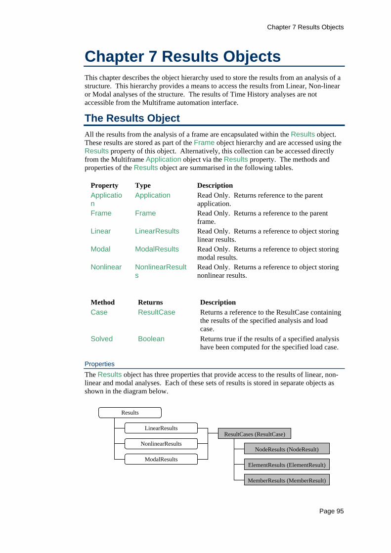
Chapter 7 Results Objects
Page 95
Chapter 7 Results Objects This chapter describes the object hierarchy used to store the results from an analysis of a structure. This hierarchy provides a means to access the results from Linear, Non-linear or Modal analyses of the structure. The results of Time History analyses are not accessible from the Multiframe automation interface.
The Results Object All the results from the analysis of a frame are encapsulated within the Results object. These results are stored as part of the Frame object hierarchy and are accessed using the Results property of this object. Alternatively, this collection can be accessed directly from the Multiframe Application object via the Results property. The methods and properties of the Results object are summarised in the following tables.
Property Type Description Application
Application Read Only. Returns reference to the parent application.
Frame Frame Read Only. Returns a reference to the parent frame.
Linear LinearResults Read Only. Returns a reference to object storing linear results.
Modal ModalResults Read Only. Returns a reference to object storing modal results.
Nonlinear NonlinearResults
Read Only. Returns a reference to object storing nonlinear results.
Method Returns Description Case ResultCase Returns a reference to the ResultCase containing
the results of the specified analysis and load case.
Solved Boolean Returns true if the results of a specified analysis have been computed for the specified load case.
Properties The Results object has three properties that provide access to the results of linear, non-linear and modal analyses. Each of these sets of results is stored in separate objects as shown in the diagram below.
Results
ResultCases (ResultCase)
NodeResults (NodeResult)
LinearResults
NonlinearResults
ElementResults (ElementResult)
MemberResults (MemberResult)
ModalResults

Chapter 7 Results Objects
Page 96
Each of the objects storing the results from the different types of analyses contains a collection of ResultCase objects. Each ResultCase object stores the results for a single load case or, in the case of the modal analysis, the results for a single mode shape.
Methods The Case method of the Results object provides a means of obtaining the results for a particular analysis without having to navigate the object hierarchy. This method takes two parameters; the first is a variant parameter identifying the load case. For modal analyses, this parameter identifies the index of the mode shape. The second parameter in an enumerated value of type mfAnalysisType, that specifies the analysis for which the results are required. This method returns a reference to a ResultCase object containing the desired information.
Dim myResults As Multiframe.ResultCase With myFrame.Results 'Get results for linear analysis of load case 3 Set myResults = .Case(3) 'Get modal results using Case method Set myResults = .Case(3, mfAnalysisModal) End With
The Results object provides another method to complement the Case method that determines if the results for a particular case have been computed by an analysis. The Solved method takes the same parameters as the Case method and returns a value of true if the specified analysis has been performed. The above example could be recoded as
Dim myResults As Multiframe.ResultCase With myFrame.Results 'Get results for linear analysis of load case 3 If (.Solved(3)) then Set myResults = .Case(3) End If If (.Solved(3, mfAnalysisModal)) then 'Get modal results using Case method Set myResults = .Case(3, mfAnalysisModal) End If End With
Result Cases For any of the analyses performed by Multiframe, the ResultCase object encapsulates a single set of data describing the displacements of a frame and the resulting actions within its members. For a linear or non-linear static analysis, the ResultCase object contains the results for the analysis of a single load case. A collection of ResultCase objects is stored by each of the LinearResults and NonlinearResults objects, each item in these collections corresponds directly to the results from the analysis of each load case applied to the model. The modal analysis results, stored in the ModalAnalysis object, are also contained within a ResultCases object. In this case, each item in the collection corresponds to a single mode. The properties of the ResultCase object are listed below.
Property Type Description Analysis mfAnalysisTyp
e Read Only. Returns the type of analysis used to generate the results.

Chapter 7 Results Objects
Page 97
Property Type Description Application Application Read Only. Returns a reference to the
parent application. ElementResults
ElementResults
Read Only. Returns a reference to the object that contains the results for the elements in the frame.
Frame Frame Read Only. Returns a reference to the parent frame object.
Index Long Read Only. Returns the index of the case. MemberResults
MemberResults
Read Only. Returns a reference to the object that contains the results for the members in the frame.
Name String Read Only. Returns the name of the case. NodeResults NodeResults Read Only. Returns a reference to the
object that contains the results for the nodes in the frame.
Number Long Read Only. Same as Index property. Solved Boolean Read Only. Returns true if the results for
this case have been solved for. The results at each node in the frame are stored as a collection of NodeResult object. Similarly the results for each element and member are stored in collections of ElementResult and MemberResult objects. These three collections are reference from the ResultCase object via the properties NodeResults, ElementResults and MemberResults. The Solved property of the ResultCase object is a Boolean property that returns true if the results of this case have been computed.
Linear and Non-linear Results The results of static linear analyses are accessed via the Linear property of the Results object. This property returns a reference to a LinearResults object that contains the results for the linear analysis of each load case. These results are stored in a ResultCases collection object, with each item in the collection corresponding directly to a load case applied to the structural model.
Property Type Description Application
Application Read Only. Returns a reference to the parent application.
Cases ResultCases
Read Only. Returns a reference to the object that contains results at the nodes, elements and members in the frame.
Frame Frame Read Only. Returns a reference to the parent frame object.
An identical structure is provided to access the results of non-linear static analyses. The Nonlinear property of the Results object returns a reference of a NonlinearResults object that contains a collection of ResultCase objects, each corresponding directly to the load cases applied to the frame.
Chapter 7 Results Objects
Page 98
Dim myResults As Multiframe.ResultCase With myFrame.Results 'Get results for linear analysis of load case 3 Set myResults = .Linear.Cases(3) 'Get same results using Case method Set myResults = .Case(3, mfAnalysisStatic) 'Get nonlinear results for load case named "DL + LL Set myResults=.Case("DL + LL", mfAnalysisStaticNonlinear) End With
A ResultCase object for either a linear of non-linear analysis will exist for each load case in the model irrespective of whether the case has been analysed. The Solved property of the ResultCase object returns a value of true if the particular case has been analysed and the results are available.
Modal Results The results of a modal analysis are accessed via the Modal property of the Results object. This property returns a reference to a ModalResults object that contains the results for all the mode shapes computed by the analysis. The properties of the ModalResults object are outlined in the table below.
Property Type Description Application Application Read Only. Returns a reference to the parent
application. Cases ResultCase
s Read Only. Returns a reference to the object that contains results at the nodes, elements and members in the frame.
Frame Frame Read Only. Returns a reference to the parent frame object.
Frequencies Variant Read Only. Returns an array containing the natural frequencies computed by the modal analysis.
Frequency Double Read Only. Returns the natural frequency of the specified mode shape.
ModalMass Double Read Only. Returns the modal mass of the specified mode shape.
NoOfModes Long Read Only. Returns the number of modes computed by the modal analysis.
ParticipationFactor
Double Read Only. Returns the participation factor of the specified mode shape for the specified degree of freedom.
ParticipationRatio Double Read Only. Returns the participating mass ratio of the specified mode shape for the specified degree of freedom.
The modal displacements are stored in a ResultCases collection object; each item in the collection corresponds to a single mode shape computed by the analysis. These results are referenced as follows.
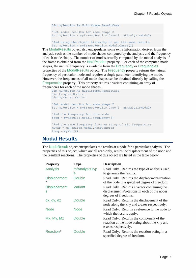
Chapter 7 Results Objects
Page 99
Dim myResults As Multiframe.ResultCase 'Get modal results for mode shape 2 Set myResults = myFrame.Results.Case(2, mfAnalysisModal) 'And using the object hierarchy to get the same results Set myResults = myFrame.Results.Modal.Cases(2)
The ModalResults object also encapsulates some extra information derived from the analysis such as the number of mode shapes computed by the analysis and the frequency of each mode shape. The number of modes actually computed by the modal analysis of the frame is obtained from the NoOfModes property. For each of the computed mode shapes, the natural frequency is available from the Frequency or Frequencies properties of the ModalResults object. The Frequency property returns the natural frequency of particular mode and requires a single parameter identifying the mode. However, the frequencies of all mode shapes can be obtained directly by calling the Frequencies property. This property returns a variant containing an array of frequencies for each of the mode shapes.
Dim myResults As Multiframe.ResultCase Dim freq as Double Dim myVar as Variant 'Get modal results for mode shape 2 Set myResults = myFrame.Results.Case(2, mfAnalysisModal) 'And the frequency for this mode freq = myResults.Modal.Frequency(2) ’And the same frequency from an array of all frequencies myVar = myResults.Modal.Frequencies freq = myVar(2)
Nodal Results The NodeResult object encapsulates the results at a node for a particular analysis. The properties of this object, which are all read-only, return the displacement of the node and the resultant reactions. The properties of this object are listed in the table below.
Property Type Description Analysis mfAnalysisTyp
e Read Only. Returns the type of analysis used to generate the results.
Displacement*
Double Read Only. Returns the displacement/rotation of the node in a specified degree of freedom.
Displacements
Variant Read Only. Returns a vector containing the displacements/rotations in each of the nodes degrees of freedoms.
dx, dy, dz Double Read Only. Returns the displacement of the node along the x, y and z-axes respectively.
Node Node Read Only. Returns a reference to the node to which the results apply.
Mx, My, Mz Double Read Only. Returns the component of the reaction at the node acting about the x, y and z-axes respectively.
Reaction* Double Read Only. Returns the reaction acting in a specified degree of freedom.

Chapter 7 Results Objects
Page 100
Property Type Description Reactions Variant Read Only. Returns a vector containing the
reactions acting in each of the nodes degrees of freedoms.
ResultCase ResultCase Read Only. Returns a reference to the parent Results Case containing these results.
Rx, Ry, Rz Double Read Only. Returns the component of the reaction at the node acting along the x, y and z-axes respectively.
Solved Boolean Read Only. Returns true if the results for this case has been computed.
Thetax Double Read Only. Returns the rotation of the node about the x-axis.
Thetay Double Read Only. Returns the rotation of the node about the y-axis.
Theta Double Read Only. Returns the rotation of the node about the z-axis.
*Denotes a property that takes a parameter specifying a nodal degree of freedom. The Application and Frame properties are common to many objects and are described in Chapter 2. The NodeResult object has no methods. The NodeResult object can be obtained for a node even if the specified analysis has not been performed. As such, the Solved property has been provided to determine if the results are available. This property returns true if the results for the node are available for the associated type of analysis. Trying to access many other properties of this object will return and error if the results have not been solved for. As such, it is good programming practice to determine if the results are available prior to accessing the other properties of the NodeResult object. The displacements at a node can be obtained in three different ways using the properties of the NodeResult object. The appropriate means of access if often dependent upon the script in which the values are used. The first technique for accessing the displacements is via the individual properties representing the displacement in each degree of freedom. The translation of the node is obtained via the properties dx, dy and dz while the rotational displacements are specified by the properties thetax, thetay, thetaz. These properties all return the displacement of the node in terms of the global coordinate system. The second method of accessing the displacements at a node is using the Displacement property of the NodeResult object. This property returns the displacement for a specified degree of freedom. The distinction of this member as a property and not a method is purely academic since it is read only. However, it is a special type of property that takes a single enumerated parameter identifying the degree of freedom.

Chapter 7 Results Objects
Page 101
The final means of accessing the displacements is using the Displacements property. This property returns a variant containing an array of six real numbers that are the displacements for each degree of freedom at the node. This property is the fastest method of accessing all the displacements at a node, as it only requires a single call to the automation interface. The displacements returned by any of these properties is specified in terms of either the displacement or rotation units currently in use by the Multiframe application. The following example demonstrates the use of all three techniques of accessing the displacements in determining the total distance moved by a node.
Dim myResult As Multiframe.NodeResult Dim dist As Double Dim i As Long Dim myVar As Variant ’Get results at Node 5 for linear analysis of load case 1 Set myResult = myFrame.Results.Case(1,mfAnalysisStatic).NodeResults(5) ’Test if results are solved If (myResult.Solved) then '(1)Compute distance moved by node dist = myResult.dx ^ 2 + myResult.dy ^ 2 + myResult.dz ^ 2 dist = Sqr(dist) '(2)Compute distance moved by node dist = 0# For i = 1 To 3 dist = dist + myResult.Displacement(i) ^ 2 Next dist = Sqr(dist) '(3)Compute distance moved by node myVar = myResult.Displacements dist = myVar(1) ^ 2 + myVar(2) ^ 2 + myVar(3) ^ 2 dist = Sqr(dist) Endif
A similar interface is also provided to access the reactions at a node. The properties, Rx, Ry, Rz and Mx, My, Mz return the reactions in each degree of freedom. Alternatively the Reaction property returns the reaction for a specified degree of freedom while the Reactions method returns an array of the reactions at the node. The values returned by each of these properties is specified in terms of either the force or moment units currently in use by the Multiframe application. The Node property of the NodeResult object returns a reference to a Node object that identifies the node to which the results apply. The analysis used to generate the results can be determined from the Analysis property of the NodeResult object. This property returns an enumerated value of type mfAnalysisType.
Element Results The actions and displacement of a single element resulting from an analysis are represented in the automation interface by the ElementResult object. The properties of this object, which are all read-only, are listed in the table below. The object also provides methods for accessing the actions at any position along the element and for constructing diagrams of the distribution of actions along the element. These properties and methods are as follows;
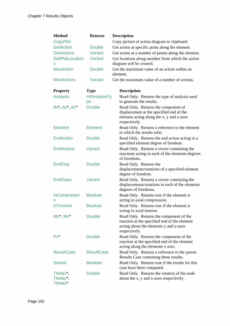
Chapter 7 Results Objects
Page 102
Method Returns Description CopyPlot Copy picture of action diagram to clipboard. GetAction Double Get action at specific point along the element. GetActions Variant Get action at a number of points along the element. GetPlotLocations
Variant Get locations along member from which the action diagram will be created.
MaxAction Double Get the maximum value of an action within an element.
MaxActions Variant Get the maximum value of a number of actions.
Property Type Description Analysis mfAnalysisTy
pe Read Only. Returns the type of analysis used to generate the results.
dx*, dy*, dz* Double Read Only. Returns the component of displacement at the specified end of the element acting along the x, y and z-axes respectively.
Element Element Read Only. Returns a reference to the element to which the results refer.
EndAction Double Read Only. Returns the end action acting in a specified element degree of freedom.
EndActions Variant Read Only. Returns a vector containing the reactions acting in each of the elements degrees of freedoms.
EndDisp Double Read Only. Returns the displacements/rotations of a specified element degree of freedom.
EndDisps Variant Read Only. Returns a vector containing the displacements/rotations in each of the elements degrees of freedoms.
InCompression
Boolean Read Only. Returns true if the element is acting in axial compression.
InTension Boolean Read Only. Returns true if the element is acting in axial tension.
My*, Mz* Double Read Only. Returns the component of the reaction at the specified end of the element acting about the elements y and z-axes respectively.
Px* Double Read Only. Returns the component of the reaction at the specified end of the element acting along the elements x-axis.
ResultCase ResultCase Read Only. Returns a reference to the parent Results Case containing these results.
Solved Boolean Read Only. Returns true if the results for this case have been computed.
Thetax*, Thetay*, Thetaz*
Double Read Only. Returns the rotation of the node about the x, y and z-axes respectively.
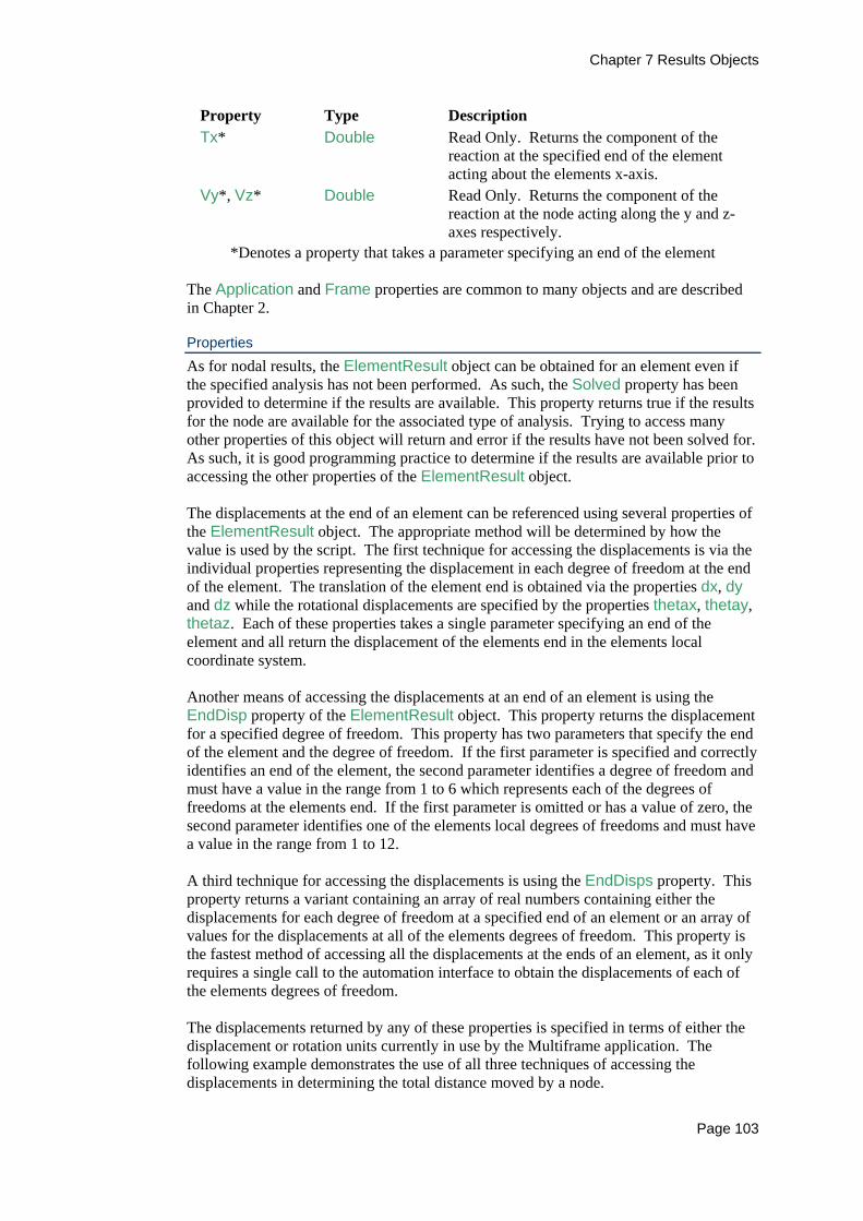
Chapter 7 Results Objects
Page 103
Property Type Description Tx* Double Read Only. Returns the component of the
reaction at the specified end of the element acting about the elements x-axis.
Vy*, Vz* Double Read Only. Returns the component of the reaction at the node acting along the y and z-axes respectively.
*Denotes a property that takes a parameter specifying an end of the element The Application and Frame properties are common to many objects and are described in Chapter 2.
Properties As for nodal results, the ElementResult object can be obtained for an element even if the specified analysis has not been performed. As such, the Solved property has been provided to determine if the results are available. This property returns true if the results for the node are available for the associated type of analysis. Trying to access many other properties of this object will return and error if the results have not been solved for. As such, it is good programming practice to determine if the results are available prior to accessing the other properties of the ElementResult object. The displacements at the end of an element can be referenced using several properties of the ElementResult object. The appropriate method will be determined by how the value is used by the script. The first technique for accessing the displacements is via the individual properties representing the displacement in each degree of freedom at the end of the element. The translation of the element end is obtained via the properties dx, dy and dz while the rotational displacements are specified by the properties thetax, thetay, thetaz. Each of these properties takes a single parameter specifying an end of the element and all return the displacement of the elements end in the elements local coordinate system. Another means of accessing the displacements at an end of an element is using the EndDisp property of the ElementResult object. This property returns the displacement for a specified degree of freedom. This property has two parameters that specify the end of the element and the degree of freedom. If the first parameter is specified and correctly identifies an end of the element, the second parameter identifies a degree of freedom and must have a value in the range from 1 to 6 which represents each of the degrees of freedoms at the elements end. If the first parameter is omitted or has a value of zero, the second parameter identifies one of the elements local degrees of freedoms and must have a value in the range from 1 to 12. A third technique for accessing the displacements is using the EndDisps property. This property returns a variant containing an array of real numbers containing either the displacements for each degree of freedom at a specified end of an element or an array of values for the displacements at all of the elements degrees of freedom. This property is the fastest method of accessing all the displacements at the ends of an element, as it only requires a single call to the automation interface to obtain the displacements of each of the elements degrees of freedom. The displacements returned by any of these properties is specified in terms of either the displacement or rotation units currently in use by the Multiframe application. The following example demonstrates the use of all three techniques of accessing the displacements in determining the total distance moved by a node.

Chapter 7 Results Objects
Page 104
Dim myResult As Multiframe.NodeResult Dim dist As Double Dim i As Long Dim myVar As Variant ’Get results at Node 5 for linear analysis of load case 1 Set myResult = myFrame.Results.Case(1,mfAnalysisStatic).NodeResults(5) ’Test if results are solved If (myResult.Solved) then '(1)Compute distance moved by node dist = myResult.dx ^ 2 + myResult.dy ^ 2 + myResult.dz ^ 2 dist = Sqr(dist) '(2)Compute distance moved by node dist = 0# For i = 1 To 3 dist = dist + myResult.Displacement(i) ^ 2 Next dist = Sqr(dist) '(3)Compute distance moved by node myVar = myResult.Displacements dist = myVar(1) ^ 2 + myVar(2) ^ 2 + myVar(3) ^ 2 dist = Sqr(dist) Endif
A similar interface is also provided to access the actions at the ends of the element. The properties, Px, Vy, Vz and Tx, My, Mz return the actions at each end of the member. These may also be returned by referencing a particular degree of freedom using the EndActions property while the EndActions method returns an array of the end action at a specified end of the element or an array of values for all of the elements degrees of freedom. The values returned by each of these properties is specified in terms of either the force or moment units currently in use by the Multiframe application. Two properties of the ElementResult object allow the user to quickly determine if the element is in tension or compression without worrying about sign conventions. The InTension property will return true if the element is in axial tension while the InCompression property returns a value of true if the element is in axial compression. The Element property of the ElementResult object returns a reference to an Element object that identifies the elements to which the results apply. The analysis used to generate the results can also be determined using the Analysis property of the ElementResult object, which returns an enumerated value of type mfAnalysisType.
Methods The GetAction and GetActions methods of the ElementResult object provide access to the displacements and actions along an element. The GetAction method returns the value of a specified action or displacement at a specified location along the member. The GetActions method extends this functionality and returns an array of values for the action at a number of specified locations. For example, the following code demonstrates how to determine the moments at quarter points along an element.

Chapter 7 Results Objects
Page 105
Dim myResult As Multiframe.ElementResult Dim myVar As Variant Dim M1,M2,M3 as Double ’Get results for element 5 (linear analysis of load case 1) Set myResult = myFrame.Elements(5).Results(1,mfAnalysisStatic) ’Test if results are solved If (myResult.Solved) then 'Get actions at quarter points M1 = myResult.GetAction(mfActionMz,0.25) M2 = myResult.GetAction(mfActionMz,0.5) M3 = myResult.GetAction(mfActionMz,0.75) 'Alternatively get actions at quarter points using single call myVar = myResult.GetActions(mfActionMz,Array(0.25,0.5,0.75)) M1 = myVar[1] M2 = myVar[2] M3 = myVar[2] Endif
The maximum values of an action or displacement along an element can be obtained using the MaxAction and MaxActions properties of the ElementResult object. The MaxAction method returns the maximum value for a single action while the MaxActions method is used to compute the maximum value of a list of actions. The methods each take two parameters; the first specifies the action or actions to be considered. The second parameter in an enumerated value of type mfSign that identifies whether to maximum negative, positive or absolute value of the action is to be computed. The following example demonstrates using these methods to compute the design actions for an element
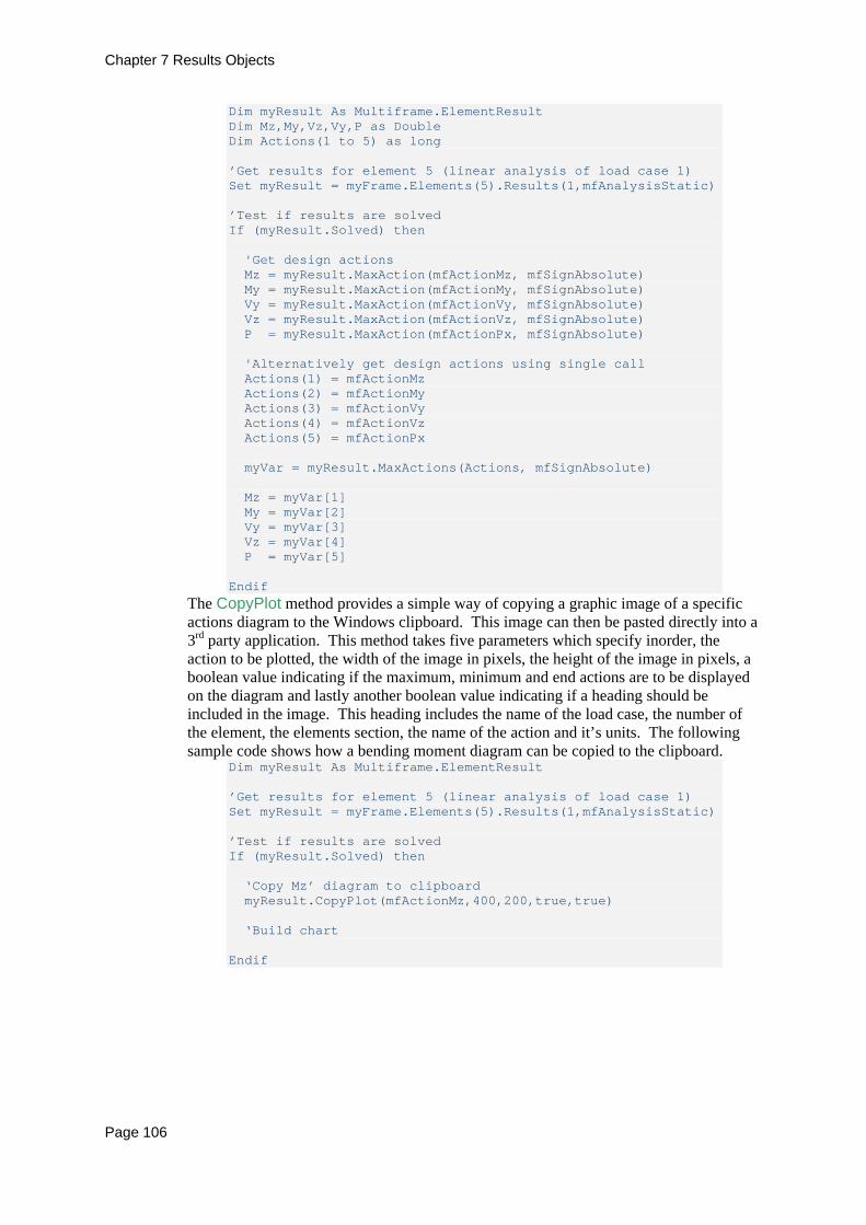
Chapter 7 Results Objects
Page 106
Dim myResult As Multiframe.ElementResult Dim Mz,My,Vz,Vy,P as Double Dim Actions(1 to 5) as long ’Get results for element 5 (linear analysis of load case 1) Set myResult = myFrame.Elements(5).Results(1,mfAnalysisStatic) ’Test if results are solved If (myResult.Solved) then 'Get design actions Mz = myResult.MaxAction(mfActionMz, mfSignAbsolute) My = myResult.MaxAction(mfActionMy, mfSignAbsolute) Vy = myResult.MaxAction(mfActionVy, mfSignAbsolute) Vz = myResult.MaxAction(mfActionVz, mfSignAbsolute) P = myResult.MaxAction(mfActionPx, mfSignAbsolute) 'Alternatively get design actions using single call Actions(1) = mfActionMz Actions(2) = mfActionMy Actions(3) = mfActionVy Actions(4) = mfActionVz Actions(5) = mfActionPx myVar = myResult.MaxActions(Actions, mfSignAbsolute) Mz = myVar[1] My = myVar[2] Vy = myVar[3] Vz = myVar[4] P = myVar[5] Endif
The CopyPlot method provides a simple way of copying a graphic image of a specific actions diagram to the Windows clipboard. This image can then be pasted directly into a 3rd party application. This method takes five parameters which specify inorder, the action to be plotted, the width of the image in pixels, the height of the image in pixels, a boolean value indicating if the maximum, minimum and end actions are to be displayed on the diagram and lastly another boolean value indicating if a heading should be included in the image. This heading includes the name of the load case, the number of the element, the elements section, the name of the action and it’s units. The following sample code shows how a bending moment diagram can be copied to the clipboard.
Dim myResult As Multiframe.ElementResult ’Get results for element 5 (linear analysis of load case 1) Set myResult = myFrame.Elements(5).Results(1,mfAnalysisStatic) ’Test if results are solved If (myResult.Solved) then ‘Copy Mz’ diagram to clipboard myResult.CopyPlot(mfActionMz,400,200,true,true) ‘Build chart Endif
Chapter 7 Results Objects
Page 107
The locations of actions along the element used to construct a plot of an action such as a bending moment or shear diagram can be obtained using the GetPlotLocations method of the Element object. This function takes single parameter that specifies the action to be plotted and returns an array containing the distances along the member at which the action needs to be computed to construct the diagram of the specified action. This array can be passed directly to the GetActions method to obtain to values of the actions at each location in the plot. This information can then be used to construct a custom plot of the data. The example that follows demonstrates how to construct a chart that plots the bending moments along the major axis of an element.
Dim myResult As Multiframe.ElementResult Dim Mz,My,Vz,Vy,P as Double Dim vLocations as Variant ’Get results for element 5 (linear analysis of load case 1) Set myResult = myFrame.Elements(5).Results(1,mfAnalysisStatic) ’Test if results are solved If (myResult.Solved) then 'Get plot locations and actions vLocations= myResult.GetPlotLocations(mfActionMz) My = myResult.GetAction(mfActionMy, vLocations) ‘Build chart Endif
Member Results When designing members it is necessary to determine the actions acting upon the member. Rather that require the actions be determined for the elements forming the member, the automation interface provides a direct interface to the actions within a design member via the MemberResult object. The properties and methods of this object are the same as those for the ElementResult object except that the results apply to a specific design member rather than element.


Chapter 8 Sections Library
Page 109
Chapter 8 Sections Library The Section, SectionGroup and SectionsLibrary objects and their associated lists and collections represent the hierarchy of the sections library and assist in the manipulation of this data. Each group of sections within the sections library is represented by a SectionGroup object. The sections within each of the groups are stored as a collection of Section objects. This object encapsulates and the information about a single section such as its names and section properties. The sections library itself is managed via the SectionsLibrary object that is responsible not only for storing the data but also for the opening and saving a sections library within Multiframe. SectionsLibrary
SectionGroups (SectionGroup)
Materials (Material)
Sections (Section)
SectionsLibrary Object The sections library open within Multiframe is represented via the SectionsLibrary object. This object contains a hierarchy of objects representing the groups, sections and materials stored within the library. In addition, this object is responsible for managing the loading and saving of the sections library to disk. The following tables list the properties and methods of the SectionsLibrary object.
Property Type Description Application Application Read Only. Returns a reference to the
parent application. FullName String Read Only. Returns the file name and path
of the sections library. Groups SectionGroups Read Only. Returns a reference to
collection of section groups stored in the library.
Materials Materials Read Only. Returns a reference to collection of materials contained in the library.
Modified Boolean Read Only. Returns true if the sections library has been modified and the changes have not been saved to disk.
Name String Read Only. Returns the file name of the sections library.
Path String Read Only. Returns the directory path of the sections library.
Method Returns Description GetSection Section Returns a reference to a specified section. Open Loads a sections library from file.

Chapter 8 Sections Library
Page 110
Method Returns Description Save Saves the sections library to its original
file. SaveAs Saves the sections library to a specified
file.
Properties The three methods FullName, Name, and Path describe the location of the sections library file. The Path property contains the disk path of the file, the Name property returns the name of the file while the FullName property returns the name of the file including the path. The Modified property is used to determine if the library has been changed and needs to be saved. This property returns a value of true if the sections library has been altered. It will most commonly be used conjunction with the methods to open and save the library. The SectionGroups and Materials properties return collections containing the groups and material stored within the sections library.
Methods A new library is loaded into Multiframe using the Open method of the SectionsLibrary object. The following script demonstrates how to open a new sections library using VBA and Microsoft Excel. In this example the user is prompted to select the library to be opened via the File Open dialog.
Dim Filename As String 'name of file to open Dim Filter As String ‘filter for section library files ’Display open file dialog so user can pick new library Filter = "Sections Library (*.slb),*.slb” With Application Filename =.GetOpenFilename(Filter,, "Open Sections Library",,False) End With If Filename <> False ThenCall mfApp.SectionsLibrary.Open(Filename) End If
In Microsoft Word this script would be slightly different as a different function is used to display the File Open dialog.
’Display open file dialog so user can pick new library With Application.Dialogs(wdDialogFileOpen) .Name = "*.slb" If (.Display = -1) Then ’Open new sections libray Call mfApp.SectionsLibrary.Open(.name,true) End If End With
The sections library may be saved to file using the Save or SaveAs methods. The Save method saves the library using it’s current file name and path. The SaveAs method saves the library as a new file. It would be implemented within a script in a similar was to the examples shown above for opening a library.
Chapter 8 Sections Library
Page 111
The simplest way to access a section within the sections library is using the GetSection method. This method provides a means of accessing a particular section without having to navigate the object hierarchy of the sections library. This method can take up to two parameters that identify the section and returns the Section object corresponding to the specified section. The first parameter is generally used to identify the group containing the section. This can be any variant value used to represent a group such as its number, name or a SectionGroup object. The second parameter is also a variant value and is used to identify the section. This may be the index of the section within the group, or it’s name. The GetSection object may also be used with only a single parameter that specifies the name of the section. In this case, the entire library will be searched to find a section with a matching name. The many ways in which the GetSection method may be used are demonstrated in the following code.
Dim mySection as Multiframe.Section Dim myGroup as Multiframe.SectionGroup Set mySection = mfApp.SectionsLibrary.GetSection(2,4) Set mySection = mfApp.SectionsLibrary.GetSection(“UB”,4) Set mySection = mfApp.SectionsLibrary.GetSection(“310UB40”) Set mySection = mfApp.SectionsLibrary.GetSection(“UB”,“310UB40”) Set myGroup = mfApp.SectionsLibrary.SectionGroups(“UB”) Set mySection = mfApp.SectionsLibrary.GetSection(myGroup,2)
SectionGroup Object The SectionGroup object encapsulates a group of sections within the sections library. These sections are stored within the SectionGroup object as a collection of Section objects. The properties and methods of the SectionGroup object are listed below.
Property Type Description Application Application Read Only. Returns a reference to the
parent application. Index Long Read Only. Returns the index of the
group within the sections library. Locked Boolean Read Only. Returns true if the group is
locked. Name String Read Only. Returns the name of group. Number Long Read Only. Same as Index. SectionNames Variant Read Only. Returns an array containing
the names of all the sections in the group. Sections Sections Read Only. Returns a reference to the
collection of the section in the group. SectionsLibrary
SectionsLibrary Read Only. Returns a reference to the parent sections library object.

Chapter 8 Sections Library
Page 112
Creating a new group A new section group is added to a sections library using the AddGroup method of the SectionGroups collection. This method accepts three parameters that specify the name of the group, the shape of sections to be stored within the group and a Boolean parameter that specifies if the default property fields for the specified shape are to be automatically constructed by Multiframe. As property fields cannot be created or modified via the automation interface, this last parameter should always be set equal to true. The shape of the section to be contained within the group is specified as an enumerated value of type mfSectionShape that has values for all of standard shapes supported within Multiframe.
Dim myGroup as Multiframe.SectionGroup Dim myGroups as Multiframe.SectionGroups Dim Name as String ’Get reference to collection of section groups Set myGroups = mfApp.SectionsLibrary.Groups ' Prompt user to enter name for group. Name = InputBox(“Enter name of group”,“Multiframe”,“New Group”) ’ If name is valid than add new group to contain I-sections ’ Default property fields for I-sections will be created If (Len(Name)>0) then Set myGroup = myGroups.AddGroup(Name,mfSectionI,true) End If
The InputBox function is a VBA function that displays a dialog in which the user is prompted to enter a text string.
Properties The name of the group is interfaced via the Name property of the SectionGroup object. This property is a string that can be up to 31 characters long. To be consistent with the other Multiframe objects, the name of the group can also be referenced via the hidden Label property of the SectionGroup object The Locked property of a SectionGroup is a Boolean value that is set equal to true if the group is locked and cannot be modified. This also excludes the modification of any sections contained within the group. The sections contained within this group are stored within a collection of Section objects that is accessed via the Sections property of the SectionGroup object. A useful property of the SectionGroup object is the SectionsNames property. It returns a list of names of all the sections contained within the group. The names of the sections are listed in the order in which they appear within the Sections collection contained within this group. This method can be used to rapidly provide data to a user form or dialog containing a list of groups from which the user may choose a section. The SectionsLibrary and Application objects return the parent objects containing this SectionGroup object.
Chapter 8 Sections Library
Page 113
Sections Object The Section object stores the data describing a single section within the sections library. Most of the properties in this object provide access to all of the geometric properties of the section that are used for analysis and design. Other properties store the sections name, its shape and details of it symmetry. The properties of the Section object are listed in the four tables shown below. The first two tables lists all the properties and method of the Section object that do not directly access the section properties of the section. The next table lists properties of the Section object that reference the dimensions of the section while the final table lists the properties for accessing the derived section properties of the section such as it’s area and moments of area.
Property Type Description Application Application Read Only. Returns a reference to the
parent application. Index Long Read Only. Returns the index of the section
in its parent group. Name String Gets/Sets the name of the section. Number Long Read Only. Same as Index. SectionGroup SectionGroup Read Only. Returns a reference to the
parent group object. SectionsLibrary
SectionsLibrary Read Only. Returns a reference to the parent sections library object.
Shape mfSectionShape Read Only. Returns the shape of the section.
SymmetricXX Boolean Read Only. Returns true if the section is symmetric about the x axis.
SymmetricYY Boolean Read Only. Returns true if the section is symmetric about the y axis.
Method Returns Description Compute Computes the properties of the section
from its dimensions. Delete Deletes the section from the library. GetProperty Double Gets a section property. SetProperty Sets a section property.
Property Description Enumerated Constant B Width MfSectionPropB b1 Secondary width MfSectionPropB1 b2 Tertiary width MfSectionPropB2 D Depth MfSectionPropD d1 Secondary depth MfSectionPropD1 d2 Tertiary depth MfSectionPropD2 r1 Primary Radius mfSectionPropR1 r2 Secondary Radius mfSectionPropR2 taper Taper angle mfSectionPropTaper tf Flange thickness mfSectionPropTf tw Web thickness mfSectionPropTw

Chapter 8 Sections Library
Page 114
Property Description Enumerated Constant t1 Additional thickness MfSectionPropT1 t2 Additional thickness MfSectionPropT2
Property Description Enumerated Constant Area Gross area mfSectionPropArea Asx Shear area in x-plane MfSectionPropAsx Asy Shear area in y-plane MfSectionPropAsy C Torsion Modulus mfSectionPropC E Young’s Modulus mfSectionPropE G Shear Modulus mfSectionPropG H LRFD Polar property mfSectionPropH Iu Moment of inertia about major
principle axis MfSectionPropIu
Iv Moment of inertia about minor principle axis
mfSectionPropIv
Ix Moment of inertia about major axis
mfSectionPropIx
Ixy Product of inertia mfSectionPropIxy Iy Moment of inertia about minor
axis mfSectionPropIy
J Polar moment of Inertia MfSectionPropJ Mass Nominal Mass mfSectionPropMass Perimeter Length of perimeter mfSectionPropPerimeter ru Radius of gyration about major
principle axis mfSectionPropRu
rv Radius of gyration about minor principle axis
mfSectionPropRv
rx Radius of gyration about major axis
mfSectionPropRx
ry Radius of gyration about minor axis
mfSectionPropRy
R0 Polar radius of inertia about shear centre
MfSectionPropR0
Sx Plastic Modulus about xx axis mfSectionPropSy Sy Plastic Modulus about yy axis mfSectionPropSy Su Plastic Modulus about major
axis mfSectionPropSu
Sv Plastic Modulus about minor axis
mfSectionPropSv
TanTheta Tangent of angle between principle axes and section axes
mfSectionPropTanTheta
Theta Angle between principle axes and section axes
mfSectionPropTheta
User1 User specified value MfSectionPropUser1 User2 User specified value MfSectionPropUser2 User3 User specified value MfSectionPropUser3 User4 User specified value MfSectionPropUser4
Chapter 8 Sections Library
Page 115
Property Description Enumerated Constant User5 User specified value MfSectionPropUser5 xc Position of centroid mfSectionPropXc xp Position of plastic axis mfSectionPropXp xs Position of shear centre mfSectionPropXs yc Position of centroid mfSectionPropYc yp Position of plastic axis mfSectionPropYp ys Position of shear centre mfSectionPropYs Zu1 Elastic modulus about the major
principle axis for portion of the section in the positive v direction
MfSectionPropZu1
Zu2 Elastic modulus about the major principle axis for portion of the section in the negative v direction
MfSectionPropZu2
Zv1 Elastic modulus about the minor principle axis for portion of the section in the positive u direction
MfSectionPropZv1
Zv2 Elastic modulus about the minor principle axis for portion of the section in the negative u direction
MfSectionPropZv2
Zxb Elastic modulus about the major axis for the bottom portion of the section
MfSectionPropZxb
Zxt Elastic modulus about the major axis for the top portion of the section
MfSectionPropZxt
Zyl Elastic modulus about the minor axis for the left hand portion of the section
MfSectionPropZyl
Zyr Elastic modulus about the minor axis for the right hand portion of the section
MfSectionPropZyr
Note that the naming convention for the elastic and plastic section modulii do not follow the naming convention generally adopted in the United States. In the Multiframe automation interface, the elastic plastic modulus is denoted using a Z while the plastic section modulus is denoted using an S.
Adding a new section A new section may be added to a group using the AddSection method of the Sections collection. This method takes up to ten parameters that specify the shape, name and dimensions of the sections. The last four parameters are optional and specify additional dimensions of the section that are only required by the more complicated section shapes. An example of adding a new I section to the Frame group of the sections library is demonstrated in the following code.
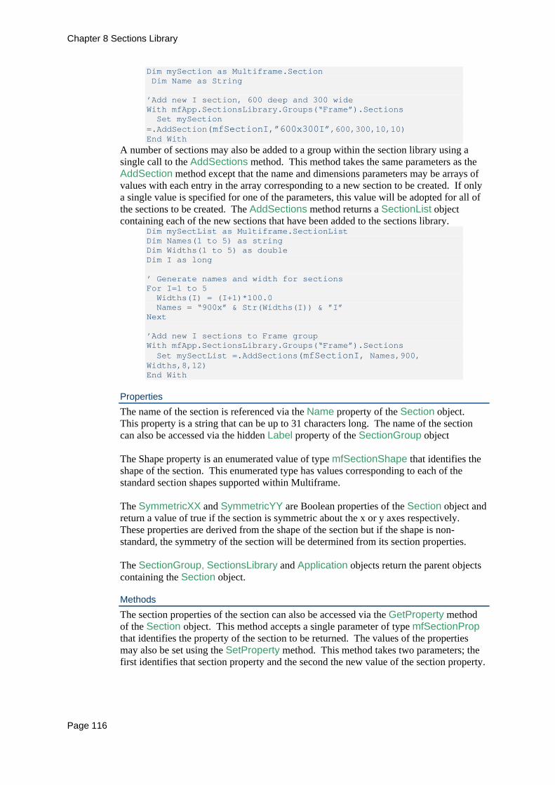
Chapter 8 Sections Library
Page 116
Dim mySection as Multiframe.Section Dim Name as String ’Add new I section, 600 deep and 300 wide With mfApp.SectionsLibrary.Groups(“Frame”).Sections Set mySection =.AddSection(mfSectionI,”600x300I”,600,300,10,10) End With
A number of sections may also be added to a group within the section library using a single call to the AddSections method. This method takes the same parameters as the AddSection method except that the name and dimensions parameters may be arrays of values with each entry in the array corresponding to a new section to be created. If only a single value is specified for one of the parameters, this value will be adopted for all of the sections to be created. The AddSections method returns a SectionList object containing each of the new sections that have been added to the sections library.
Dim mySectList as Multiframe.SectionList Dim Names(1 to 5) as string Dim Widths(1 to 5) as double Dim I as long ’ Generate names and width for sections For I=1 to 5 Widths(I) = (I+1)*100.0 Names = “900x” & Str(Widths(I)) & ”I” Next ’Add new I sections to Frame group With mfApp.SectionsLibrary.Groups(“Frame”).Sections Set mySectList =.AddSections(mfSectionI, Names,900, Widths,8,12) End With
Properties The name of the section is referenced via the Name property of the Section object. This property is a string that can be up to 31 characters long. The name of the section can also be accessed via the hidden Label property of the SectionGroup object The Shape property is an enumerated value of type mfSectionShape that identifies the shape of the section. This enumerated type has values corresponding to each of the standard section shapes supported within Multiframe. The SymmetricXX and SymmetricYY are Boolean properties of the Section object and return a value of true if the section is symmetric about the x or y axes respectively. These properties are derived from the shape of the section but if the shape is non-standard, the symmetry of the section will be determined from its section properties. The SectionGroup, SectionsLibrary and Application objects return the parent objects containing the Section object.
Methods The section properties of the section can also be accessed via the GetProperty method of the Section object. This method accepts a single parameter of type mfSectionProp that identifies the property of the section to be returned. The values of the properties may also be set using the SetProperty method. This method takes two parameters; the first identifies that section property and the second the new value of the section property.
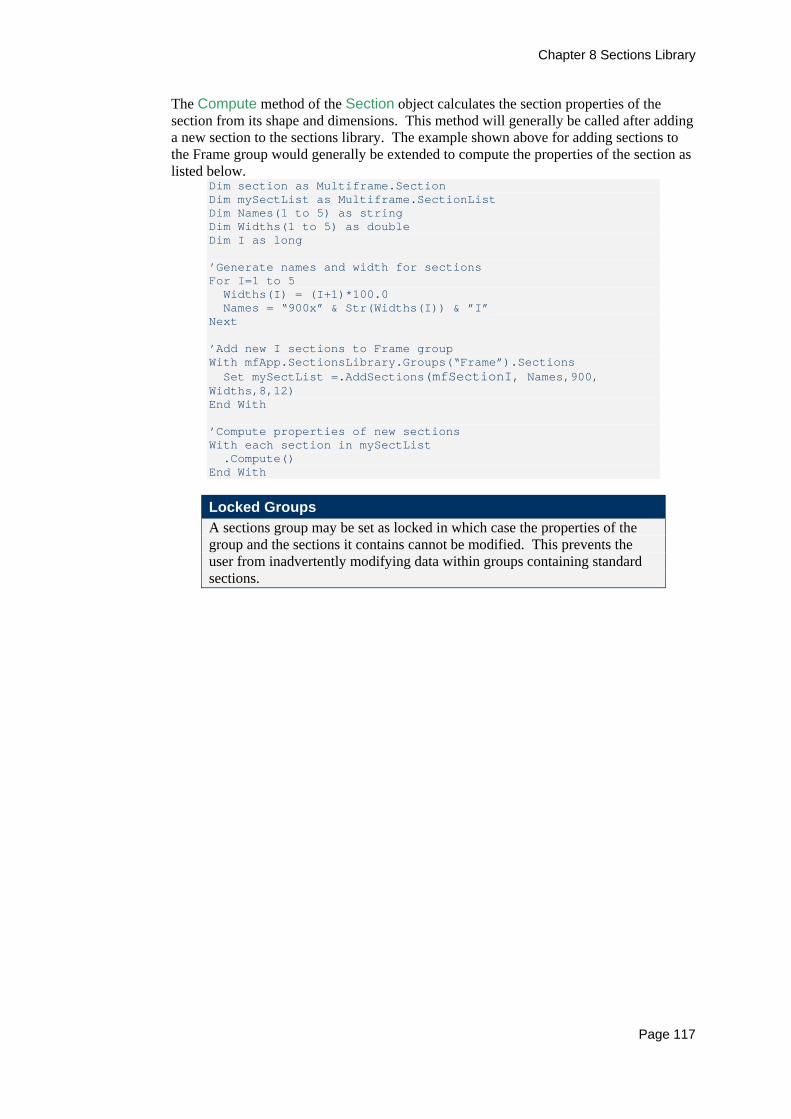
Chapter 8 Sections Library
Page 117
The Compute method of the Section object calculates the section properties of the section from its shape and dimensions. This method will generally be called after adding a new section to the sections library. The example shown above for adding sections to the Frame group would generally be extended to compute the properties of the section as listed below.
Dim section as Multiframe.Section Dim mySectList as Multiframe.SectionList Dim Names(1 to 5) as string Dim Widths(1 to 5) as double Dim I as long ’Generate names and width for sections For I=1 to 5 Widths(I) = (I+1)*100.0 Names = “900x” & Str(Widths(I)) & ”I” Next ’Add new I sections to Frame group With mfApp.SectionsLibrary.Groups(“Frame”).Sections Set mySectList =.AddSections(mfSectionI, Names,900, Widths,8,12) End With ’Compute properties of new sections With each section in mySectList .Compute() End With
Locked Groups A sections group may be set as locked in which case the properties of the group and the sections it contains cannot be modified. This prevents the user from inadvertently modifying data within groups containing standard sections.


Chapter 9 Preferences and Units
Page 119
Chapter 9 Preferences and Units The Preferences object provides access to settings that control the sign conventions and units used to display and input quantities into the Multiframe user interface. These settings also control the sign convention used within Multiframes automation interface and so it is important when automating Multiframe to ensure that any input is expressed with the current sign conventions and in the correct units. The properties and methods of the preference object are summarised in the two tables that follow.
Property Type Description Application Application Read Only. Returns a reference to the parent
application. TensionPositive
Boolean Get/Set whether distributed masses are to be used in the analysis.
UnitSet mfUnitSets Get/Set whether lumped masses are to be used in the analysis.
Method Returns Description GetUnit String Returns the name of the specified unit. SetUnit Sets the specified unit.
Sign Conventions The sign convention for axial forces used within Multiframe application is identified by the TensionPositive property of the Preferences object. When this property is set true, all axial forces within the Multiframe user interface, and the automation interface, will be displayed such that tensile forces have positive values and compressive forces negative values.
Units The Multiframe user interface allows the user to customise the units used to display and input quantities into the application. The same units settings also govern the input and output of values from the automation interface. The Preferences object provides several methods and properties for working with units. The unit set used within Multiframe to display quantities is specified by the UnitSet property. This is an enumerated value of type mfUnitSets that has values corresponding to one of predefined sets of units (Australian, Japanese, American, etc.). To use the American unit set, the following line would be added to a script
mfApp.Preferences.UnitSet = mfUnitsetAmerican The individual units within the unit set selected within the application may be determined using the GetUnit method. This method is very useful in constructing VBA forms or fields for inputting information as it provides a means of communicating the current units of measure. The GetUnit method returns a string containing the abbreviated name of the unit as specified by the single parameter of the method that identifies the type of unit (length, force, angle, etc). The individual units of measure are identified using an enumerated value of type mfUnitType. As an example, a string containing the name of the current units of length would be obtained as follows
Dim s As String s = mfApp.Preferences.GetUnit (Multiframe.mfUnitLength)

Chapter 9 Preferences and Units
Page 120
The units used within the current unit set can be changed using the SetUnit method of the Preferences object. This method takes two parameters; the first is an enumerated value of type mfUnitType that identifies the units to be changed. The second parameter is a string that specifies the name of the units to be used. For example, to change the units of length to feet would require the following line of code
mfApp.Preferences.SetUnits(mfUnitLength,”ft”) Allowable values of the unit names for each of the unit types are those listed in Multiframes Units dialog. A summary of the different units of measurement that can be set within Multiframe is listed in the table below. Unit Constant Value Dimensionless value mfUnitNone 0 Length mfUnitLength 1 Angle mfUnitAngle 2 Displacement mfUnitDisplacement 3 Angular Displacement mfUnitAngularDisplacement 4 Force mfUnitForce 5 Moment mfUnitMoment 6 Force Per Unit Length mfUnitUdl 7 Stress mfUnitStress 8 Mass mfUnitMass 9 Mass Per Unit Length mfUnitMassPerLength 10 Area mfUnitArea 11 Moment of Inertia mfUnitInertia 12 Density mfUnitDensity 13 Elastic Modulus mfUnitModulus 14 Spring stiffness mfUnitSpring 15 Torsional Spring Stiffness
mfUnitTorsionSpring 16
Temperature mfUnitTemperature 17 Coefficient of Thermal Expansion
mfUnitTemperatureCoeff 18
Rotational Mass mfUnitRotationalMass 19 Velocity mfUnitVelocity 20 Acceleration mfUnitAcceleration 21 Warping Constant mfUnitWarping 22
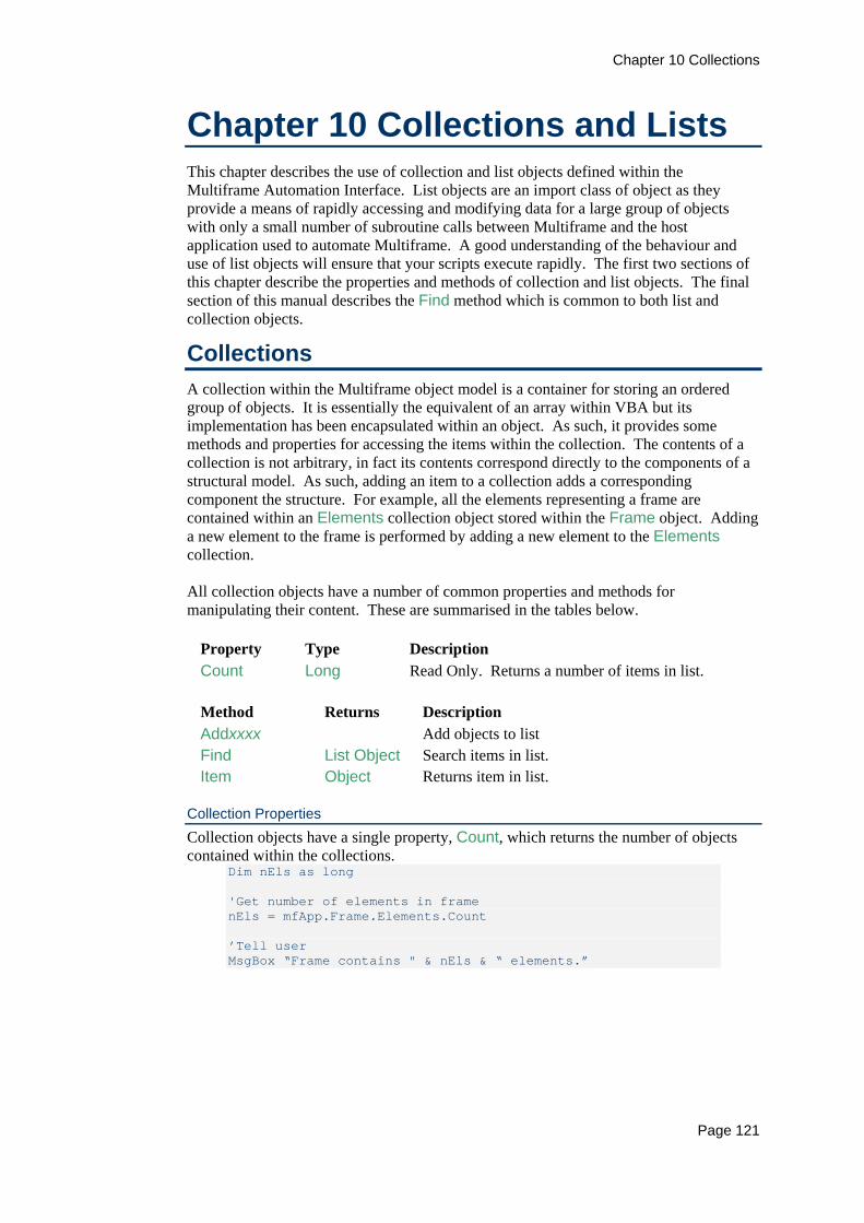
Chapter 10 Collections
Page 121
Chapter 10 Collections and Lists This chapter describes the use of collection and list objects defined within the Multiframe Automation Interface. List objects are an import class of object as they provide a means of rapidly accessing and modifying data for a large group of objects with only a small number of subroutine calls between Multiframe and the host application used to automate Multiframe. A good understanding of the behaviour and use of list objects will ensure that your scripts execute rapidly. The first two sections of this chapter describe the properties and methods of collection and list objects. The final section of this manual describes the Find method which is common to both list and collection objects.
Collections A collection within the Multiframe object model is a container for storing an ordered group of objects. It is essentially the equivalent of an array within VBA but its implementation has been encapsulated within an object. As such, it provides some methods and properties for accessing the items within the collection. The contents of a collection is not arbitrary, in fact its contents correspond directly to the components of a structural model. As such, adding an item to a collection adds a corresponding component the structure. For example, all the elements representing a frame are contained within an Elements collection object stored within the Frame object. Adding a new element to the frame is performed by adding a new element to the Elements collection. All collection objects have a number of common properties and methods for manipulating their content. These are summarised in the tables below.
Property Type Description Count Long Read Only. Returns a number of items in list.
Method Returns Description Addxxxx Add objects to list Find List Object Search items in list. Item Object Returns item in list.
Collection Properties Collection objects have a single property, Count, which returns the number of objects contained within the collections.
Dim nEls as long 'Get number of elements in frame nEls = mfApp.Frame.Elements.Count ’Tell user MsgBox “Frame contains " & nEls & “ elements.”

Chapter 10 Collections
Page 122
Collection Methods Each collection object has a method for adding new items to the frame. The name of this method will vary from collection to collection but it will always begin with the word Add. For example, a new spring is added to the frame using the AddSpring method of the Springs collection. Most collections will also feature a method for adding multiple objects to the frame. These methods are named as the plural of the method for adding a single object to the frame. Continuing the previous example, a number of springs can be added to a frame using the AddSprings method of the Springs collection. The add methods associated with each collection are described earlier in this manual in the section associated with the objects contained by the collection. An object within the collection is returned via the Item method.
Dim nEls as long 'Get number of elements in frame With mfApp.Frame.Elements .Item(1).Orientation = 45 End With
The Find method of a collection object is used to search the items in the collection for objects with properties matching a specified criterion. This method returns a list object containing the items meeting the criteria. This last section of this chapter describes this method in detail.
Lists A drawback of using automation is that calls between the applications are relatively slow. To ensure that your scripts run quickly it is important to reduce the number of calls between the applications. In Multiframe we have introduced list objects that provide a means of accessing and manipulating the properties a number of objects in a single statement. List objects are similar to collections in that they store a number of objects in an array. However, list objects can store an arbitrary group of objects while collections store all the instances of a particular type of object. For example, the Nodes collection provides a reference to all the nodes in a frame. An arbitrary subset of these nodes can be stored using the NodeList object. Each collection of objects in Multiframe has a corresponding list object that may be used to store an arbitrary list of objects. All list objects have a number of common properties and methods for manipulating their content. These are summarised in the tables below.
Property Type Description Count Long Read Only. Returns a number of items in list. Unique Boolean Get/Set whether an item can only appear in the list
once..
Method Returns Description Add Add items to the list. Clear Remove all items from the list. Delete Delete all items in the list from the frame. Find List Object Search items in list.
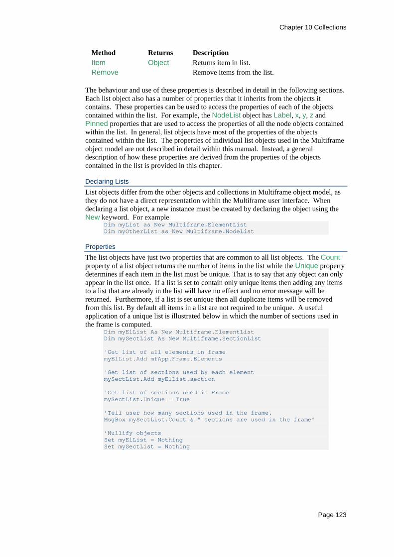
Chapter 10 Collections
Page 123
Method Returns Description Item Object Returns item in list. Remove Remove items from the list.
The behaviour and use of these properties is described in detail in the following sections. Each list object also has a number of properties that it inherits from the objects it contains. These properties can be used to access the properties of each of the objects contained within the list. For example, the NodeList object has Label, x, y, z and Pinned properties that are used to access the properties of all the node objects contained within the list. In general, list objects have most of the properties of the objects contained within the list. The properties of individual list objects used in the Multiframe object model are not described in detail within this manual. Instead, a general description of how these properties are derived from the properties of the objects contained in the list is provided in this chapter.
Declaring Lists List objects differ from the other objects and collections in Multiframe object model, as they do not have a direct representation within the Multiframe user interface. When declaring a list object, a new instance must be created by declaring the object using the New keyword. For example
Dim myList as New Multiframe.ElementList Dim myOtherList as New Multiframe.NodeList
Properties The list objects have just two properties that are common to all list objects. The Count property of a list object returns the number of items in the list while the Unique property determines if each item in the list must be unique. That is to say that any object can only appear in the list once. If a list is set to contain only unique items then adding any items to a list that are already in the list will have no effect and no error message will be returned. Furthermore, if a list is set unique then all duplicate items will be removed from this list. By default all items in a list are not required to be unique. A useful application of a unique list is illustrated below in which the number of sections used in the frame is computed.
Dim myElList As New Multiframe.ElementList Dim mySectList As New Multiframe.SectionList 'Get list of all elements in frame myElList.Add mfApp.Frame.Elements 'Get list of sections used by each element mySectList.Add myElList.section 'Get list of sections used in Frame mySectList.Unique = True ’Tell user how many sections used in the frame. MsgBox mySectList.Count & " sections are used in the frame" ’Nullify objects Set myElList = Nothing Set mySectList = Nothing

Chapter 10 Collections
Page 124
In addition to the properties common to all lists, each list object has many of the same properties as the objects it contains. However, these properties do not return a single value but a variant containing an array of values, each array entry corresponding to the value of the property for each item within the list. For example, the NodeList object has x, y and z properties describing the location of the nodes in the list. Each property returns an array of real number values representing the position of each node in the list. The properties of a list may also be used to set the values of properties of objects referenced by the list. In this case the property of the list can be set equal to a single value, in which case the same value will be applied to all items within the list, or the property can be set equal to an array of values that specifies a separate value for each item in the list. In the following example, the x-coordinate of all nodes in a frame are scales by a factor of 2.5. The script firstly extracts all the x-coordinates of each node into an array. The values in this array are then multiplied by a factor of 2.5. This array is then used to set the x-coordinates of the nodes in the list. The final line of the script then sets the z-coordinate of all the nodes in the list to zero.
Dim myNodeList as New Multiframe.NodeList Dim myVar as Variant ’Add all nodes in frame to a list of nodes myNodeList.Add mfApp.Frame.Nodes ’Get x coordinates of nodes myVar = myNodeList.x ’Scale x coords of nodes by factor of 2.5 For i=1 to Ubound(myVar) myVar(i)= myVar(i)*2.5 Next ’Set coordinates of nodes myNodeList.x = myVar myNodeList.z = 0.0
This script execute much faster than one that loops over each node in the frame and sets each coordinate separately as it significantly reduces the number of subroutine calls made between Multiframe and the host application. This script requires only three (3) inter application calls to retrieve and set the coordinates of the node. When compared to the three (3) calls per node required when looping over the individual nodes in the frame the savings in time are significant.
Methods An item is added to a list using the Add method. By adding an item to a list we are adding a reference to that item to the list. This should not be confused with the Add methods of the collection objects that create new items within the frame. To complement this method, the Remove method is used to remove items from the list. These methods take one or more variant parameters that specify the items to be added to the list. List of nodes, elements and other objects modelling the frame require only a single parameter that identifies the items to be added or removed from the list. As it is a variant value any value representing a single object or a number of objects contained by the list would be valid. For example, the contents of an ElementList object could be specified in any of the following ways

Chapter 10 Collections
Page 125
Dim myElList as New Multiframe.ElementList Dim myOtherList as New Multiframe.ElementList ’Add items to lists myElList.Add 6 ‘Add element 6 to list myElList.Add mfApp.Frame.Elements(2) ‘Add element using element object myOtherList.Add “1,2,5-10” ‘Add list of elements to list myElList.Add myOtherList ‘Add another list myElList.Clear ’Remove all elements from list myElList.Add mfApp.Frame.Elements ‘Add entire collection ’Nullify objects Set myElList = nothing Set myOtherList = nothing
This example uses the Clear method of the list object. This method, which is common to all list objects, removes all items from the list. List of items such as loads or sections allow for two parameters to be used as part of the Add method in order to specify the items to be added to the list. In these cases, the objects to be referenced by the list cannot be referenced by only their index or number and require a second parameter to specify a load case, section group or result type. The following code demonstrates how to create list of element loads.
Dim myList as New Multiframe.ElementLoadList With mfApp.Frame ’Add items to lists using loads index within a load case myList.Add 6,2 ‘Add load 6 from load case 2 myList.Add “1-5”,2 ‘Add loads 1 to 5 from case 2 myList.Add “6-10”,”DL + LL” ‘Add loads from “DL+LL” case myList.Add “1,5,9”,.LoadCases(1) ’Add loads from 1st case ’Add loads using objects myList.Add .LoadCases(1).ElementLoads(2) ‘Add load using load object myList.Add .LoadCases(1).ElementLoads ‘Add collection of loads End With
All of the items in a list can be deleted from a frame using the Delete method of a list object. Do not confuse this method with the Remove method that only removes a reference to an object from the list. The following code uses list objects to delete all the loads applied to a group of elements.
Dim myElList as New Multiframe.ElementList Dim myLoadList as New Multiframe.ElementLoadList ’Create list of elements myElList.Add “1-10” ’Get list of all loads applied to these elements Set myLoadList = myElList.Loads ’Delete these loads myLoadList.Delete
The Find method of a list object is used to search the items in the list for objects with properties matching a specified criterion. This fianl section of the manual is dedicated to this method.

Chapter 10 Collections
Page 126
The Find Method The Find method is common to most collection and list objects available via the Multiframe Object Model. This method takes 3 parameters which identify the property to be Example – Find pinned nodes
Dim myNodeList As New Multiframe.NodeList 'Find all pinned nodes myNodeList.Add mfApp.Frame.Nodes.Find("Pinned", True) Find all nodes with labels starting with ‘abc’ myNodeList.Clear myNodeList.Add mfApp.Frame.Nodes.Find("Label", "abc*")
A slight more sophisticated script is shown below in which all the elements at a particular height are obtained by firstly searching all the elements within a frame to find those with the first end position at the specified height. The results from this query, stored as an ElementList object, are then searched to find all elements that have their second end positioned at the correct height. All the elements in the resulting list of elements are then labelled as “Floor 1”.
Dim myElList As New Multiframe.ElementList 'Select all elements in first floor which is at y=5.0 Set myElList = myFrame.Elements.Find("y(1)", 4.9, 5.1) Set myElList = myElList.Find("y(2)", 4.9, 5.1) myElList.Label = “Floor 1” ’myEllist.Members.Label = “Floor 1”
Find using results Dim myList As New Multiframe.MemberResultList 'Select all elements in first floor which is at y=5.0 With mfApp.Results.Case() Set myList =.Find("y(1)", 4.9, 5.1) Set myElList = myElList.Find("y(2)", 4.9, 5.1) myElList.Label = “Floor 1” End with ’myEllist.Members.Label = “Floor 1”

Chapter 11 User Interface
Page 127
Chapter 11 User Interface Multiframes automation interface also provides a small number of objects, properties and methods for interacting with Multiframes user interface. This allows the user to interact with the selections in each of Multiframes windows and to specify the load case that is currently displayed within Multiframe. This chapter describes the objects used to interact with Multiframes user interface. The small number of properties and methods of objects used for modelling the frame that provide interaction with the user interface are described elsewhere in this manual.
Selection Object The automation interface can interact with the selection in any of Multiframes windows. The selection is stored within a Selection object that encapsulates lists of the selected items. For instance, the nodes contained within a selection are stored in a NodeList object that is returned by the Nodes property of the Selection object. Similarly the Elements property of the Selection object returns an ElementList containing each of the selected elements. The properties and methods of the Selection object are summarised in the tables below.
Property Type Description Application Application Read Only. Returns a reference to the parent
application. Elements Elementlist Get/Set list of elements contained in the selection. Frame Frame Read Only. Returns a reference to the parent frame. Members Memberlist Get/Set list of members contained in the selection.. Nodes NodeList Get/Set list of nodes contained in the selection.
Method Returns Description Clear Deselects all items in the selection. IsEmpty Boolean Returns true if no items are selected.
Using Selections The implementation of selections within the automation interface is significantly different to the other objects as a Selection object does not correspond directly to a selection within Multiframe and, as such, is not represented within object hierarchy. The advantage of this implementation is that many selections can be created, stored and manipulated without any restrictions imposed by the Multiframe application. However, the disadvantage is that a selection in a window is not automatically updated as items are added or removed from lists within a Selection object. To use a selection object, a new instance must first be created by declaring the selection using the New keyword.
Dim mySelection as New Multiframe.Selection

Chapter 11 User Interface
Page 128
The current selection in one of Multiframes windows can be obtained using the Selection property of the Frame object. This property has a single parameter that identifies the window containing the desired selection. The Selection property is read-only and so a selection can only be set using the SetSelection method of the Frame object. The methods takes up to three parameters that specify the selection, a window in which the selection is to be set, and an optional parameter specifying if the current selection in the window is to be extended. By default the SetSelection will replace any existing selection with the new selection. As an example of using the Selection object, the following code demonstrates how to set the selection in the load window to be the same as the selection in the Frame window
Dim mySelection as New Multiframe.Selection ’Get selection from Frame window Set mySelection = myFrame.Selection(mfWinFrame) ’Set selection in Load window Call myFrame.SetSelection(mySelection,mfWinLoad)
Properties The Elements property of the Selection object returns an ElementList object containing references to each of the elements in the selection. This property can be set equal to any variant value representing either a single node or a list of nodes. The following script illustrates many of the ways in which this property can be accessed.
Dim mySelection as New Multiframe.Selection Dim myEllist as New Multiframe.ElementList ’Compose list of elements to be selected myElList.Add “1-20” ’Set selection mySelection.Elements = 1 mySelection.Elements = myEllist mySelection.Elements = mfApp.Frame.Elements mySelection.Elements = “1,3,5,7” ’Select nodes at end of elements Set mySelection.Nodes = mySelection.Elements.Nodes ’Set selection in Frame window Call myFrame.SetSelection(mySelection ,mfWinFrame)
In the Multiframe user interface, the selection of nodes and elements is synchronised such that the nodes at the end of an element will automatically be selected when the element is selected. This relationship is not enforced via the Selection object and must be performed manually. The Members and Nodes properties of the Selection object returns list objects that contain references to each of the selected nodes and members. These properties behave in the same way as the Element property and can be set equal to any variant values representing a single or a group of nodes or members. A further example demonstrating the use of the Selection object and the Nodes properties is listed below.

Chapter 11 User Interface
Page 129
Dim mySelection as New Multiframe.Selection Dim myNodeList as New Multiframe.Nodelist Dim myNode as Multiframe.Node ’Get selection from Frame window Set mySelection = myFrame.Selection(mfWinFrame) ’Get list of node contained in selection myNodeList.Add (mySelection.Nodes) ’Refine selection to include only nodes that are pinned For each myNode in myNodeList.Nodes If (myNode.Pinned) myNodeList.Remove myNode Next Next ’Set selection in Frame window Call myFrame.SetSelection(mySelection ,mfWinFrame)
Methods The Clear method of the Selection object removes all items from the selection. The IsEmpty method returns true if the selection empty and contains no selected items.
Dim mySelection as New Multiframe.Selection ’Get selection from Frame window Set mySelection = myFrame.Selection(mfWinFrame) Test if anything is selected If (mySelection.IsEmpty) Then msgbox “Nothing is selected in Frame window”,,”MF Script” End If

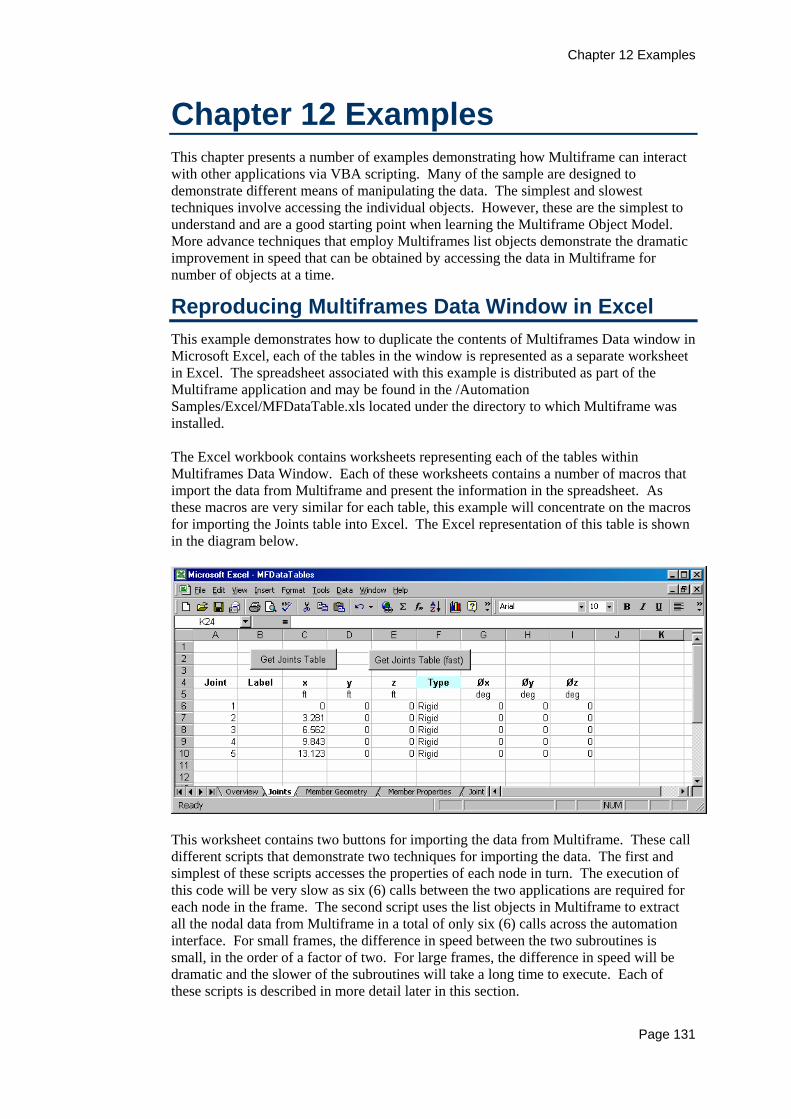
Chapter 12 Examples
Page 131
Chapter 12 Examples This chapter presents a number of examples demonstrating how Multiframe can interact with other applications via VBA scripting. Many of the sample are designed to demonstrate different means of manipulating the data. The simplest and slowest techniques involve accessing the individual objects. However, these are the simplest to understand and are a good starting point when learning the Multiframe Object Model. More advance techniques that employ Multiframes list objects demonstrate the dramatic improvement in speed that can be obtained by accessing the data in Multiframe for number of objects at a time.
Reproducing Multiframes Data Window in Excel This example demonstrates how to duplicate the contents of Multiframes Data window in Microsoft Excel, each of the tables in the window is represented as a separate worksheet in Excel. The spreadsheet associated with this example is distributed as part of the Multiframe application and may be found in the /Automation Samples/Excel/MFDataTable.xls located under the directory to which Multiframe was installed. The Excel workbook contains worksheets representing each of the tables within Multiframes Data Window. Each of these worksheets contains a number of macros that import the data from Multiframe and present the information in the spreadsheet. As these macros are very similar for each table, this example will concentrate on the macros for importing the Joints table into Excel. The Excel representation of this table is shown in the diagram below.
This worksheet contains two buttons for importing the data from Multiframe. These call different scripts that demonstrate two techniques for importing the data. The first and simplest of these scripts accesses the properties of each node in turn. The execution of this code will be very slow as six (6) calls between the two applications are required for each node in the frame. The second script uses the list objects in Multiframe to extract all the nodal data from Multiframe in a total of only six (6) calls across the automation interface. For small frames, the difference in speed between the two subroutines is small, in the order of a factor of two. For large frames, the difference in speed will be dramatic and the slower of the subroutines will take a long time to execute. Each of these scripts is described in more detail later in this section.

Chapter 12 Examples
Page 132
The Joints worksheet contains 5 subroutines; the first two subroutines are command handlers for the two buttons that appear in that worksheet. The next subroutine stored with the Joints worksheet is the SetupUnits subroutine. This subroutine is responsible for setting the unit names displayed at the top of the table in row 5 of the spreadsheet.
'Set units in title of table Private Sub SetupUnits(mfApp As Multiframe.Application) Dim s As String ' Update Units in x,y,x columns s = mfApp.Preferences.GetUnit(Multiframe.mfUnitLength) Range("JointData").offset(0, 2).Value = s Range("JointData").offset(0, 3).Value = s Range("JointData").offset(0, 4).Value = s 'Update Units in orientation columns s = mfApp.Preferences.GetUnit(Multiframe.mfUnitAngle) Range("JointData").offset(0, 6).Value = s Range("JointData").offset(0, 7).Value = s Range("JointData").offset(0, 8).Value = s End Sub
In this subroutine, the names of the length and angle units are obtained by calling the GetUnit method of the Multiframe Preferences object. These values are used to set the unit names in row 5 of the worksheet. The offset method of the Range object is used to identify a cell, relative to the JointData range, into which each value is inserted. The JointData range is a named range in the excel spreadsheet which contains the single cell A5. The subroutine GetNodalData_Slow, which is listed below, performs the insertion of the nodal data from Multiframe into Excel.

Chapter 12 Examples
Page 133
' Get Joints table Public Sub GetNodalData_Slow() Dim mfApp As Multiframe.Application Dim Node As Multiframe.Node Dim i As Long Dim s As String Dim orient As Variant 'Capture errors elegantly On Error GoTo ErrorHandler ' Get current Multiframe application Set mfApp = New Multiframe.Application 'Erase old data and set units in title ClearTable ("JointData") Call SetupUnits(mfApp) ' Write data to worksheet i = 0 For Each Node In mfApp.Frame.nodes i = i + 1 Range("JointData").offset(i, 0).Value = Node.Number Range("JointData").offset(i, 1).Value = Node.label Range("JointData").offset(i, 2).Value = Node.x Range("JointData").offset(i, 3).Value = Node.xyz(2) Range("JointData").offset(i, 4).Value = Node.z If (Node.pinned) Then s = "Pinned" Else s = "Rigid" End If Range("JointData").offset(i, 5).Value = s orient = Node.Orientation Range("JointData").offset(i, 6).Value = orient(1) Range("JointData").offset(i, 7).Value = orient(2) Range("JointData").offset(i, 8).Value = orient(3) Next 'Set format of cells With Range("JointData") Range(.offset(1, 2), .offset(i, 8)).NumberFormat = gFormat End With ErrorHandler: If (Err <> 0) Then MsgBox Err.Description End If End Sub
The first executable line of this subroutine defines the mechanism for reacting to any errors that may arise during the execution of the script. The next statements call subroutines that firstly clear the table of any existing data and then update the names of the units in the heading rows of the table using the SetupUnits subroutine described above. The ClearTable subroutine, which is defined in Module1 of the VBA project, takes a single parameter specifying a named range within the worksheet. It uses this range to construct a region to be erased by firstly selecting the column beneath this range down to the first empty cell. This selection is used to construct a range that contains the first 20 columns of the worksheet which is then is cleared of it content.
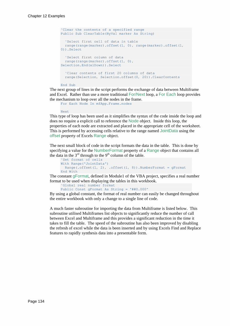
Chapter 12 Examples
Page 134
'Clear the contents of a specified range Public Sub ClearTable(ByVal marker As String) 'Select first cell of data in table range(range(marker).offset(1, 0), range(marker).offset(1, 0)).Select 'Select first column of data range(range(marker).offset(1, 0), Selection.End(xlDown)).Select 'Clear contents of first 20 columns of data range(Selection, Selection.offset(0, 20)).ClearContents End Sub
The next group of lines in the script performs the exchange of data between Multiframe and Excel. Rather than use a more traditional For/Next loop, a For Each loop provides the mechanism to loop over all the nodes in the frame.
For Each Node In mfApp.Frame.nodes Next
This type of loop has been used as it simplifies the syntax of the code inside the loop and does no require a explicit call to reference the Node object. Inside this loop, the properties of each node are extracted and placed in the appropriate cell of the worksheet. This is performed by accessing cells relative to the range named JointData using the offset property of Excels Range object. The next small block of code in the script formats the data in the table. This is done by specifying a value for the NumberFormat property of a Range object that contains all the data in the 3rd through to the 9th column of the table.
'Set format of cells With Range("JointData") Range(.offset(1, 2), .offset(i, 8)).NumberFormat = gFormat End With
The constant gFormat, defined in Module1 of the VBA project, specifies a real number format to be used when displaying the tables in this workbook.
'Global real number format Public Const gFormat As String = "##0.000"
By using a global constant, the format of real number can easily be changed throughout the entire workbook with only a change to a single line of code. A much faster subroutine for importing the data from Multiframe is listed below. This subroutine utilised Multiframes list objects to significantly reduce the number of call between Excel and Multiframe and this provides a significant reduction in the time it takes to fill the table. The speed of the subroutine has also been improved by disabling the refresh of excel while the data is been inserted and by using Excels Find and Replace features to rapidly synthesis data into a presentable form.
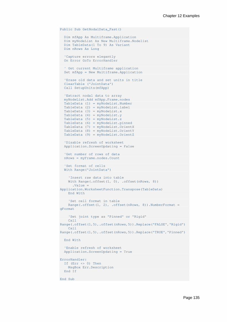
Chapter 12 Examples
Page 135
Public Sub GetNodalData_Fast() Dim mfApp As Multiframe.Application Dim myNodeList As New Multiframe.Nodelist Dim TableData(1 To 9) As Variant Dim nRows As Long 'Capture errors elegantly On Error GoTo ErrorHandler ' Get current Multiframe application Set mfApp = New Multiframe.Application 'Erase old data and set units in title ClearTable ("JointData") Call SetupUnits(mfApp) 'Extract nodal data to array myNodeList.Add mfApp.Frame.nodes TableData (1) = myNodeList.Number TableData (2) = myNodeList.label TableData (3) = myNodeList.x TableData (4) = myNodeList.y TableData (5) = myNodeList.z TableData (6) = myNodeList.pinned TableData (7) = myNodeList.OrientX TableData (8) = myNodeList.OrientY TableData (9) = myNodeList.OrientZ 'Disable refresh of worksheet Application.ScreenUpdating = False 'Get number of rows of data nRows = myFrame.nodes.Count 'Set format of cells With Range("JointData") 'Insert raw data into table With Range(.offset(1, 0), .offset(nRows, 8)) .Value = Application.WorksheetFunction.Transpose(TableData) End With 'Set cell format in table Range(.offset(1, 2), .offset(nRows, 8)).NumberFormat = gFormat 'Set joint type as "Pinned" or "Rigid" Call Range(.offset(1,5),.offset(nRows,5)).Replace("FALSE","Rigid") Call Range(.offset(1,5),.offset(nRows,5)).Replace("TRUE","Pinned") End With 'Enable refresh of worksheet Application.ScreenUpdating = True ErrorHandler: If (Err <> 0) Then MsgBox Err.Description End If End Sub
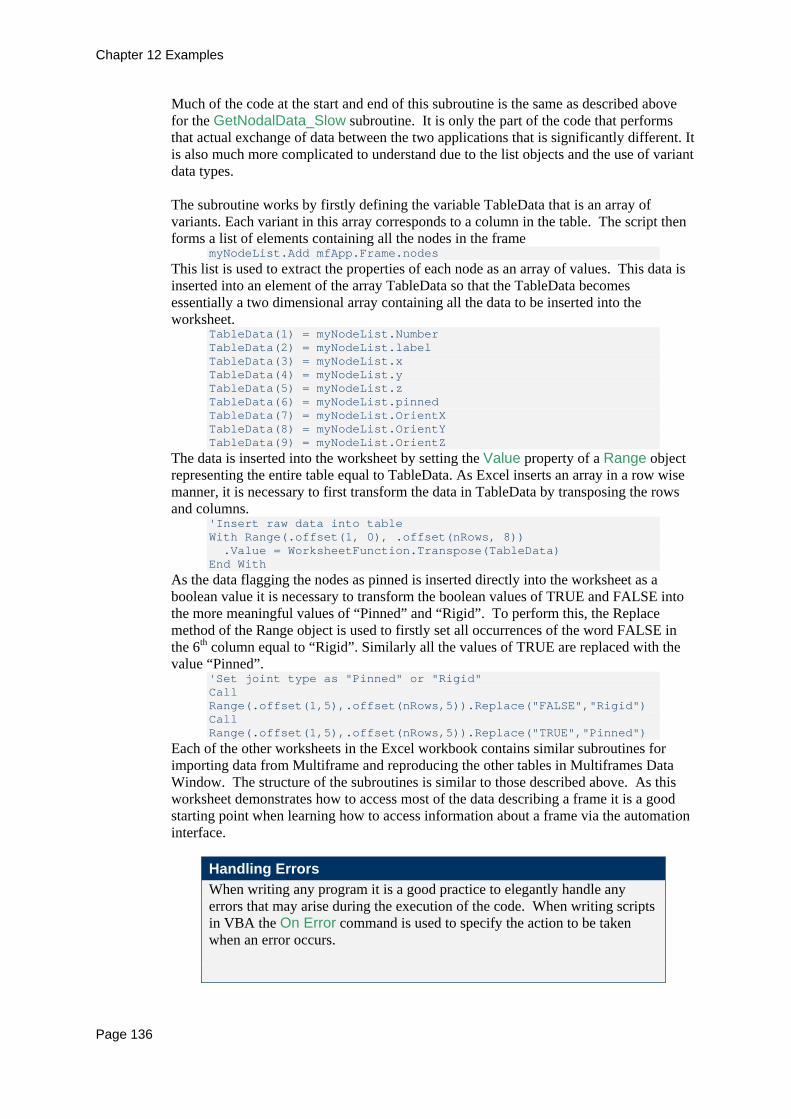
Chapter 12 Examples
Page 136
Much of the code at the start and end of this subroutine is the same as described above for the GetNodalData_Slow subroutine. It is only the part of the code that performs that actual exchange of data between the two applications that is significantly different. It is also much more complicated to understand due to the list objects and the use of variant data types. The subroutine works by firstly defining the variable TableData that is an array of variants. Each variant in this array corresponds to a column in the table. The script then forms a list of elements containing all the nodes in the frame
myNodeList.Add mfApp.Frame.nodes This list is used to extract the properties of each node as an array of values. This data is inserted into an element of the array TableData so that the TableData becomes essentially a two dimensional array containing all the data to be inserted into the worksheet.
TableData(1) = myNodeList.Number TableData(2) = myNodeList.label TableData(3) = myNodeList.x TableData(4) = myNodeList.y TableData(5) = myNodeList.z TableData(6) = myNodeList.pinned TableData(7) = myNodeList.OrientX TableData(8) = myNodeList.OrientY TableData(9) = myNodeList.OrientZ
The data is inserted into the worksheet by setting the Value property of a Range object representing the entire table equal to TableData. As Excel inserts an array in a row wise manner, it is necessary to first transform the data in TableData by transposing the rows and columns.
'Insert raw data into table With Range(.offset(1, 0), .offset(nRows, 8)) .Value = WorksheetFunction.Transpose(TableData) End With
As the data flagging the nodes as pinned is inserted directly into the worksheet as a boolean value it is necessary to transform the boolean values of TRUE and FALSE into the more meaningful values of “Pinned” and “Rigid”. To perform this, the Replace method of the Range object is used to firstly set all occurrences of the word FALSE in the 6th column equal to “Rigid”. Similarly all the values of TRUE are replaced with the value “Pinned”.
'Set joint type as "Pinned" or "Rigid" Call Range(.offset(1,5),.offset(nRows,5)).Replace("FALSE","Rigid") Call Range(.offset(1,5),.offset(nRows,5)).Replace("TRUE","Pinned")
Each of the other worksheets in the Excel workbook contains similar subroutines for importing data from Multiframe and reproducing the other tables in Multiframes Data Window. The structure of the subroutines is similar to those described above. As this worksheet demonstrates how to access most of the data describing a frame it is a good starting point when learning how to access information about a frame via the automation interface.
Handling Errors When writing any program it is a good practice to elegantly handle any errors that may arise during the execution of the code. When writing scripts in VBA the On Error command is used to specify the action to be taken when an error occurs.
Chapter 12 Examples
Page 137
In the subroutines presented above, the On Error command is used to specify that in the event of an error, execution of the script will be redirect to the label ErrorHandler. This label is at the very bottom of the subroutines and is followed by three lines of code that firstly determine if an error occurred and then report the error message to the user using the standard message box dialog. It is important to test for an error, as these three lines will be executed whenever the subroutines are executed irrespective of whether and error occurred or not.
Reproducing Multiframes Result Window in Excel Following on from the previous example, this example demonstrates how to duplicate the contents of Multiframes Result window in Microsoft Excel. Each of the tables in this window is represented as a separate worksheet in Excel. The spreadsheet associated with this example is distributed as part of the Multiframe application and may be found in the /Automation Samples/Excel/MFResultTable.xls located under the directory to which Multiframe was installed. The structure of the subroutines in this workbook is the same as those used in the previous example. For a description of the VBA scripts you should refer to that example.
Customised Reporting using Word In this example, Microsoft Word is used to construct a printed report describing the frame currently opened within Multiframe. The example is contained in the file MFReport.doc which is distributed with Multiframe and can be found in the /Automation Samples/Word directory under the file path to which Multiframe was installed. The report is generated as a series of tables describing the elements of the structure, the loading and, if available, the results. Each table in the report is generated by a separate subroutine. These have been grouped into 4 modules within the VBA project. The FrameTables module contains the subroutines for generating the tables describing the structure, the LoadTables module contains those for reporting loads and the ResultTable module encapsulates all the subroutines for outputting the results. The 4th module, named Utilities, contains some utility subroutines used to create tables and format the report. The MFReport.doc document contains two buttons. The Generate Report button is used to run the Generate Report The GenerateReport subroutine is the main routine for compiling the report. It calls all the subroutines for generating the individual tables within the report and is responsible for creating the titles to the various sections of the report. This subroutine is also used to set the values of some global variables that store the names of some commonly used units, and for setting the contents of the headers and footers in the report.

Chapter 12 Examples
Page 138
All of the subroutines for generating a table within the report have the same structure and use the same techniques for extracting the data from Multiframe and creating a table containing that information. The InsertMbrGeomTable() subroutine, which is listed below, is a typical example of these subroutines. This subroutine inserts a table containing the properties of elements within the frame. It is written to minimise the number of calls between Word and Multiframe by using the ElementList object. By adding all the elements in the frame to an ElementList, the value of a single element property can be obtained for each element in the frame in a single call to Multiframe. These values are stored in a variant variable that contains an array of values, each value corresponding to an element within the frame. The subroutine begins by obtaining all of the data to be presented in the table and storing this data as in arrays declared as variants.

Chapter 12 Examples
Page 139
Sub InsertMbrGeomTable() Dim nEls As Long Dim element, node1, node2 As Variant Dim length, slope, orient As Variant Dim SectionName, GroupName As Variant Dim list As New Multiframe.ElementList Dim myTable As Table Dim i As Long nEls = mfApp.Frame.Elements.Count If (nEls > 0) Then 'Import data from Multfframe list.Add mfApp.Frame.Elements element = list.Number node1 = list.NodeIndex(1) node2 = list.NodeIndex(2) SectionName = list.Section.Name GroupName = list.Section.SectionGroup.Name length = list.length slope = list.slope orient = list.Orientation 'Create new paragraph and insert headings for table Call StartTable("Member", "Joint 1", "Joint 2", "Group", _ "Section", "Orientation", "Length", "Slope") 'Insert tab delimited text that will form table For i = 1 To nEls Selection.InsertAfter element(i) & vbTab & _ Str(node1(i)) & vbTab & _ Str(node2(i)) & vbTab & _ GroupName(i) & vbTab & _ SectionName(i) & vbTab & _ Format(orient(i), gFormat) & vbTab & _ Format(length(i), gFormat) & vbTab & _ Format(slope(i), gFormat) & vbCr Next 'Create table from tabbed text and set default style Call CreateTable(myTable, 1) 'Add units to header row With myTable.Rows(1) .Cells(6).Range.InsertAfter vbVerticalTab + sAngle .Cells(7).Range.InsertAfter vbVerticalTab + sLength .Cells(8).Range.InsertAfter vbVerticalTab + sAngle End With Else Call EmptyTableMessage("Members") End If End Sub
Rather than insert a table and set the contents of each cell in the table, the data is inserted into the document as tab delimited text. This delimited text is then converted into a table.
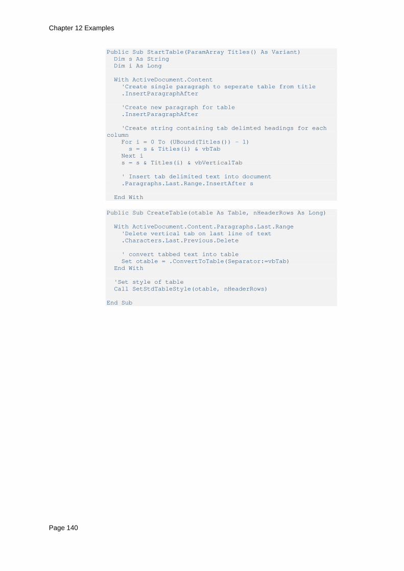
Chapter 12 Examples
Page 140
Public Sub StartTable(ParamArray Titles() As Variant) Dim s As String Dim i As Long With ActiveDocument.Content 'Create single paragraph to seperate table from title .InsertParagraphAfter 'Create new paragraph for table .InsertParagraphAfter 'Create string containing tab delimted headings for each column For i = 0 To (UBound(Titles()) - 1) s = s & Titles(i) & vbTab Next i s = s & Titles(i) & vbVerticalTab ' Insert tab delimited text into document .Paragraphs.Last.Range.InsertAfter s End With
Public Sub CreateTable(otable As Table, nHeaderRows As Long) With ActiveDocument.Content.Paragraphs.Last.Range 'Delete vertical tab on last line of text .Characters.Last.Previous.Delete ' convert tabbed text into table Set otable = .ConvertToTable(Separator:=vbTab) End With 'Set style of table Call SetStdTableStyle(otable, nHeaderRows) End Sub
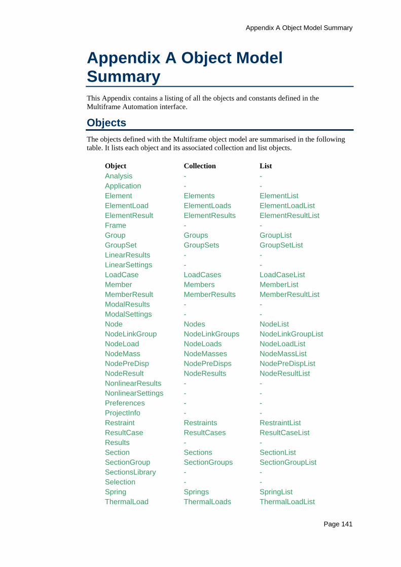
Appendix A Object Model Summary
Page 141
Appendix A Object Model Summary This Appendix contains a listing of all the objects and constants defined in the Multiframe Automation interface.
Objects The objects defined with the Multiframe object model are summarised in the following table. It lists each object and its associated collection and list objects.
Object Collection List Analysis - - Application - - Element Elements ElementList ElementLoad ElementLoads ElementLoadList ElementResult ElementResults ElementResultList Frame - - Group Groups GroupList GroupSet GroupSets GroupSetList LinearResults - - LinearSettings - - LoadCase LoadCases LoadCaseList Member Members MemberList MemberResult MemberResults MemberResultList ModalResults - - ModalSettings - - Node Nodes NodeList NodeLinkGroup NodeLinkGroups NodeLinkGroupList NodeLoad NodeLoads NodeLoadList NodeMass NodeMasses NodeMassList NodePreDisp NodePreDisps NodePreDispList NodeResult NodeResults NodeResultList NonlinearResults - - NonlinearSettings - - Preferences - - ProjectInfo - - Restraint Restraints RestraintList ResultCase ResultCases ResultCaseList Results - - Section Sections SectionList SectionGroup SectionGroups SectionGroupList SectionsLibrary - - Selection - - Spring Springs SpringList ThermalLoad ThermalLoads ThermalLoadList
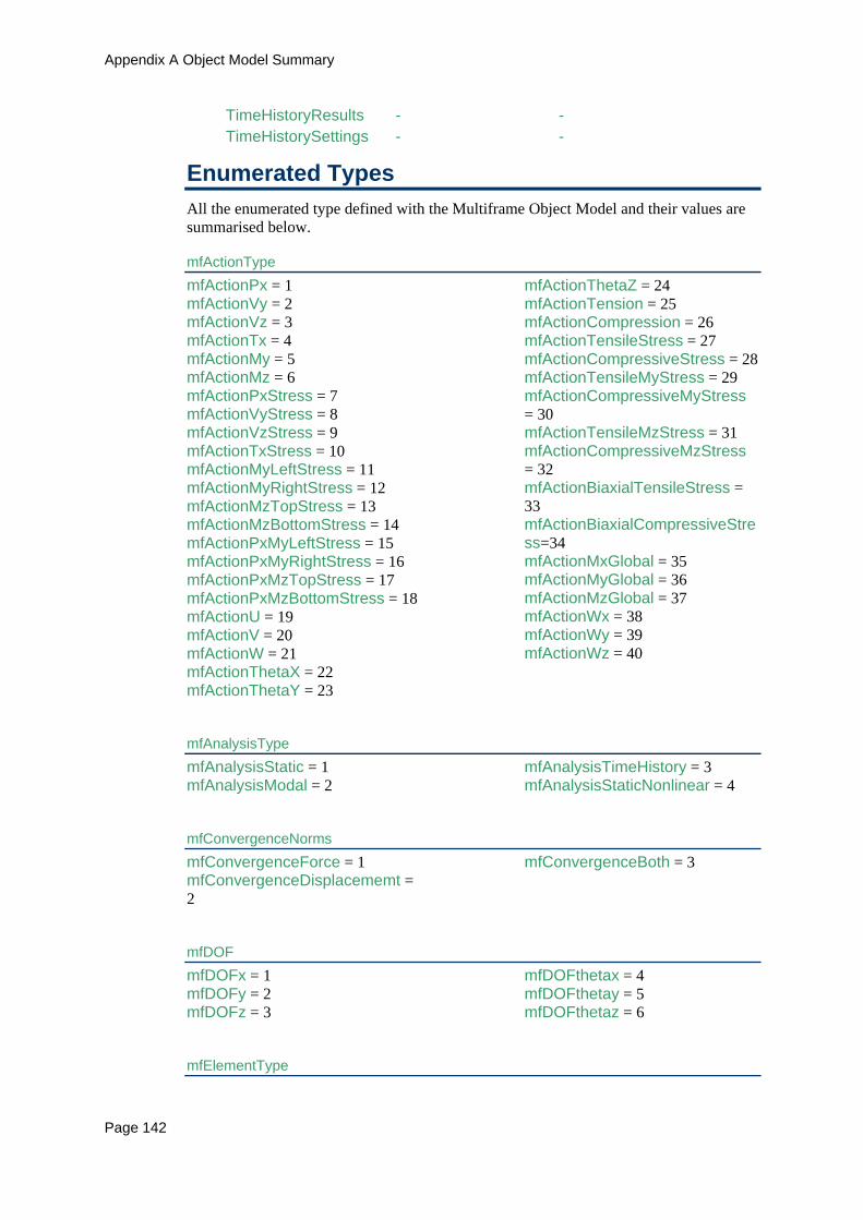
Appendix A Object Model Summary
Page 142
TimeHistoryResults - - TimeHistorySettings - -
Enumerated Types All the enumerated type defined with the Multiframe Object Model and their values are summarised below.
mfActionType mfActionPx = 1 mfActionVy = 2 mfActionVz = 3 mfActionTx = 4 mfActionMy = 5 mfActionMz = 6 mfActionPxStress = 7 mfActionVyStress = 8 mfActionVzStress = 9 mfActionTxStress = 10 mfActionMyLeftStress = 11 mfActionMyRightStress = 12 mfActionMzTopStress = 13 mfActionMzBottomStress = 14 mfActionPxMyLeftStress = 15 mfActionPxMyRightStress = 16 mfActionPxMzTopStress = 17 mfActionPxMzBottomStress = 18 mfActionU = 19 mfActionV = 20 mfActionW = 21 mfActionThetaX = 22 mfActionThetaY = 23
mfActionThetaZ = 24 mfActionTension = 25 mfActionCompression = 26 mfActionTensileStress = 27 mfActionCompressiveStress = 28 mfActionTensileMyStress = 29 mfActionCompressiveMyStress = 30 mfActionTensileMzStress = 31 mfActionCompressiveMzStress = 32 mfActionBiaxialTensileStress = 33 mfActionBiaxialCompressiveStress=34 mfActionMxGlobal = 35 mfActionMyGlobal = 36 mfActionMzGlobal = 37 mfActionWx = 38 mfActionWy = 39 mfActionWz = 40
mfAnalysisType mfAnalysisStatic = 1 mfAnalysisModal = 2
mfAnalysisTimeHistory = 3 mfAnalysisStaticNonlinear = 4
mfConvergenceNorms mfConvergenceForce = 1 mfConvergenceDisplacememt = 2
mfConvergenceBoth = 3
mfDOF mfDOFx = 1 mfDOFy = 2 mfDOFz = 3
mfDOFthetax = 4 mfDOFthetay = 5 mfDOFthetaz = 6
mfElementType
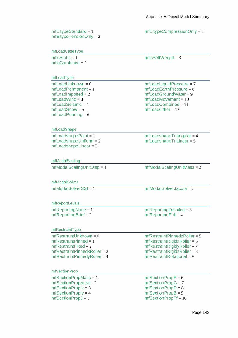
Appendix A Object Model Summary
Page 143
mfEltypeStandard = 1 mfEltypeTensionOnly = 2
mfEltypeCompressionOnly = 3
mfLoadCaseType mflcStatic = 1 mflcCombined = 2
mflcSelfWeight = 3
mfLoadType mfLoadUnknown = 0 mfLoadPermanent = 1 mfLoadImposed = 2 mfLoadWind = 3 mfLoadSeismic = 4 mfLoadSnow = 5 mfLoadPonding = 6
mfLoadLiquidPressure = 7 mfLoadEarthPressure = 8 mfLoadGroundWater = 9 mfLoadMovement = 10 mfLoadCombined = 11 mfLoadOther = 12
mfLoadShape mfLoadshapePoint = 1 mfLoadshapeUniform = 2 mfLoadshapeLinear = 3
mfLoadshapeTriangular = 4 mfLoadshapeTriLinear = 5
mfModalScaling mfModalScalingUnitDisp = 1 mfModalScalingUnitMass = 2
mfModalSolver mfModalSolverSSI = 1 mfModalSolverJacobi = 2
mfReportLevels mfReportingNone = 1 mfReportingBrief = 2
mfReportingDetailed = 3 mfReportingFull = 4
mfRestraintType mfRestraintUnknown = 0 mfRestraintPinned = 1 mfRestraintFixed = 2 mfRestraintPinnedxRoller = 3 mfRestraintPinnedyRoller = 4
mfRestraintPinnedzRoller = 5 mfRestraintRigidxRoller = 6 mfRestraintRigidyRoller = 7 mfRestraintRigidzRoller = 8 mfRestraintRotational = 9
mfSectionProp mfSectionPropMass = 1 mfSectionPropArea = 2 mfSectionPropIx = 3 mfSectionPropIy = 4 mfSectionPropJ = 5
mfSectionPropE = 6 mfSectionPropG = 7 mfSectionPropD = 8 mfSectionPropB = 9 mfSectionPropTf = 10
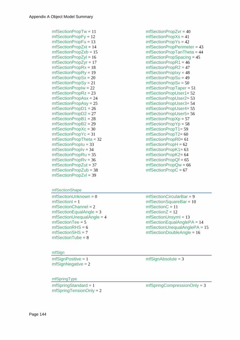
Appendix A Object Model Summary
Page 144
mfSectionPropTw = 11 mfSectionPropFy = 12 mfSectionPropFu = 13 mfSectionPropZxt = 14 mfSectionPropZxb = 15 mfSectionPropZyl = 16 mfSectionPropZyr = 17 mfSectionPropRx = 18 mfSectionPropRy = 19 mfSectionPropSx = 20 mfSectionPropSy = 21 mfSectionPropIw = 22 mfSectionPropRz = 23 mfSectionPropAsx = 24 mfSectionPropAsy = 25 mfSectionPropD1 = 26 mfSectionPropD2 = 27 mfSectionPropB1 = 28 mfSectionPropB2 = 29 mfSectionPropXc = 30 mfSectionPropYc = 31 mfSectionPropTheta = 32 mfSectionPropIu = 33 mfSectionPropIv = 34 mfSectionPropRu = 35 mfSectionPropRv = 36 mfSectionPropZut = 37 mfSectionPropZub = 38 mfSectionPropZvl = 39
mfSectionPropZvr = 40 mfSectionPropXs = 41 mfSectionPropYs = 42 mfSectionPropPerimeter = 43 mfSectionPropTanTheta = 44 mfSectionPropSpacing = 45 mfSectionPropR1 = 46 mfSectionPropR2 = 47 mfSectionPropIxy = 48 mfSectionPropSu = 49 mfSectionPropSv = 50 mfSectionPropTaper = 51 mfSectionPropUser1= 52 mfSectionPropUser2= 53 mfSectionPropUser3= 54 mfSectionPropUser4= 55 mfSectionPropUser5= 56 mfSectionPropXp = 57 mfSectionPropYp = 58 mfSectionPropT1= 59 mfSectionPropT2= 60 mfSectionPropR0= 61 mfSectionPropH = 62 mfSectionPropK1= 63 mfSectionPropK2= 64 mfSectionPropQf = 65 mfSectionPropQw = 66 mfSectionPropC = 67
mfSectionShape mfSectionUnknown = 0 mfSectionI = 1 mfSectionChannel = 2 mfSectionEqualAngle = 3 mfSectionUnequalAngle = 4 mfSectionTee = 5 mfSectionRHS = 6 mfSectionSHS = 7 mfSectionTube = 8
mfSectionCircularBar = 9 mfSectionSquareBar = 10 mfSectionC = 11 mfSectionZ = 12 mfSectionUnsymI = 13 mfSectionEqualAnglePA = 14 mfSectionUnequalAnglePA = 15 mfSectionDoubleAngle = 16
mfSign mfSignPositive = 1 mfSignNegative = 2
mfSignAbsolute = 3
mfSpringType mfSpringStandard = 1 mfSpringTensionOnly = 2
mfSpringCompressionOnly = 3

Appendix A Object Model Summary
Page 145
mfUnitSets mfUnitsetAmerican = 1 mfUnitsetAustralian = 2 mfUnitsetBritish = 3
mfUnitsetCanadian = 4 mfUnitsetEuropean = 5 mfUnitsetJapanese = 6
mfUnitType mfUnitNone = 0 mfUnitLength = 1 mfUnitAngle = 2 mfUnitDisplacement = 3 mfUnitAngularDisplacement = 4 mfUnitForce = 5 mfUnitMoment = 6 mfUnitUdl = 7 mfUnitStress = 8 mfUnitMass = 9 mfUnitMassPerLength = 10 mfUnitArea = 11
mfUnitInertia = 12 mfUnitDensity = 13 mfUnitModulus = 14 mfUnitSpring = 15 mfUnitTorsionSpring = 16 mfUnitTemperature = 17 mfUnitTemperatureCoeff = 18 mfUnitRotationalMass = 19 mfUnitVelocity = 20 mfUnitAcceleration = 21 mfUnitWarping = 22
mfWindow mfWinActive = 0 mfWinFrame = 1 mfWinData = 2 mfWinLoad = 3
mfWinResults = 4 mfWinPlot = 5 mfWinCalcsheet = 6 mfWinReport = 7

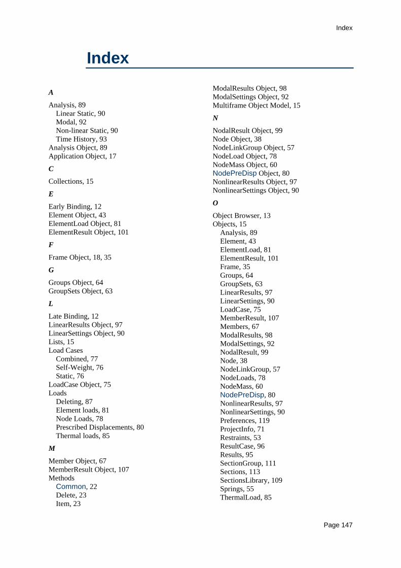
Index
Page 147
Index
A
Analysis, 89 Linear Static, 90 Modal, 92 Non-linear Static, 90 Time History, 93
Analysis Object, 89 Application Object, 17
C
Collections, 15
E
Early Binding, 12 Element Object, 43 ElementLoad Object, 81 ElementResult Object, 101
F
Frame Object, 18, 35
G
Groups Object, 64 GroupSets Object, 63
L
Late Binding, 12 LinearResults Object, 97 LinearSettings Object, 90 Lists, 15 Load Cases
Combined, 77 Self-Weight, 76 Static, 76
LoadCase Object, 75 Loads
Deleting, 87 Element loads, 81 Node Loads, 78 Prescribed Displacements, 80 Thermal loads, 85
M
Member Object, 67 MemberResult Object, 107 Methods
Common, 22 Delete, 23 Item, 23
ModalResults Object, 98 ModalSettings Object, 92 Multiframe Object Model, 15
N
NodalResult Object, 99 Node Object, 38 NodeLinkGroup Object, 57 NodeLoad Object, 78 NodeMass Object, 60 NodePreDisp Object, 80 NonlinearResults Object, 97 NonlinearSettings Object, 90
O
Object Browser, 13 Objects, 15
Analysis, 89 Element, 43 ElementLoad, 81 ElementResult, 101 Frame, 35 Groups, 64 GroupSets, 63 LinearResults, 97 LinearSettings, 90 LoadCase, 75 MemberResult, 107 Members, 67 ModalResults, 98 ModalSettings, 92 NodalResult, 99 Node, 38 NodeLinkGroup, 57 NodeLoads, 78 NodeMass, 60 NodePreDisp, 80 NonlinearResults, 97 NonlinearSettings, 90 Preferences, 119 ProjectInfo, 71 Restraints, 53 ResultCase, 96 Results, 95 SectionGroup, 111 Sections, 113 SectionsLibrary, 109 Springs, 55 ThermalLoad, 85

Index
Page 148
TimeHistorySettings, 93 OLE_COLOR, 66
P
Preferences Object, 17, 119 ProjectInfo Object, 71 Properties
Count, 23 Unique, 23
Properties Application, 22 Common, 22 Frame, 22 Index, 22 Label, 22 Number, 22
R
Restraint Object, 53 ResultCase Object, 96 Results, 95
Results Object, 95
S
SectionGroup Object, 111 Sections Object, 113 SectionsLibrary object, 17 SectionsLibrary Object, 109 Sign Conventions, 119 Spring Object, 55
T
ThermalLoad Object, 85 TimeHistorySettings
Objects, 93
U
Units, 119
V
VBA, 9