Embed Size (px)
Citation preview
Multiframe Steel Codes
Windows Version 16
User Manual
© Bentley Systems, Incorporated 2013

iii
License & Copyright
Multiframe Steel Codes software & User Manual © 2013 Bentley Systems, Incorporated

v
Table of Contents
License & Copyright ........................................................................................................ iii Table of Contents ............................................................................................................... v About this manual .............................................................................................................. 1 Chapter 1 Getting Started .................................................................................................. 3
About Multiframe Steel Codes ................................................................................ 3 Design Codes ........................................................................................................... 3 Installing Multiframe Steel Codes ........................................................................... 4
Starting Multiframe Steel Codes ................................................................... 4 Adding or Removing Steel Design Codes ..................................................... 4
Design Overview ...................................................................................................... 4 Design Members ............................................................................................ 4 Bending Checks ............................................................................................. 4 Tension Checks .............................................................................................. 4 Compression Checks...................................................................................... 5 Combined Checks .......................................................................................... 5 Serviceability Checks .................................................................................... 5 Seismic Checks .............................................................................................. 5 Checking a member ....................................................................................... 5 Designing a member ...................................................................................... 5 Reporting ....................................................................................................... 5
Windows .................................................................................................................. 6 Frame Window .............................................................................................. 6 Data Window ................................................................................................. 6 Result Window .............................................................................................. 6 Plot Window .................................................................................................. 6 Report Window .............................................................................................. 7
Design Members ...................................................................................................... 7 Viewing Results Using Design Members ................................................................ 8
Design Member Symbols ............................................................................... 8 Rendering Design Members .......................................................................... 9
Coordinate Systems.................................................................................................. 9 Properties for Design ............................................................................................... 9 Shear Area .............................................................................................................. 10
Chapter 2 Using Multiframe Steel Codes ....................................................................... 11 Design Procedure ................................................................................................... 11 Working with Design Members ............................................................................. 12 Setting Design Properties ....................................................................................... 12 Setting Design Properties ....................................................................................... 13 Setting Section Type .............................................................................................. 15 Setting Steel Grade ................................................................................................ 15 Setting Design Constraints ..................................................................................... 18 Setting Section Constraints .................................................................................... 18 Setting Frame Type ................................................................................................ 19 Setting Allowable Stresses ..................................................................................... 19 Setting Acceptance Ratio ....................................................................................... 20 Setting Capacity Factors ........................................................................................ 20 Checking a Frame .................................................................................................. 20
Displaying Efficiency .................................................................................. 22 Governing Load Cases ................................................................................. 22
Designing a Frame ................................................................................................. 23 Optimum Sections........................................................................................ 24 Tips On Optimisation .................................................................................. 25
vi
Finding Design Values ................................................................................ 25 Printing ................................................................................................................... 25
Printing the Report Window ........................................................................ 26 Saving your Work .................................................................................................. 26 Saving the report .................................................................................................... 26
Chapter 3 ASD and AIJ ................................................................................................... 27 Design Checks - ASD and AIJ ............................................................................... 27 Bending - ASD and AIJ ......................................................................................... 27
Design Constraints (AIJ) ............................................................................. 27 Unbraced Length - ASD and AIJ ................................................................. 27 Bending Coefficient (ASD) ......................................................................... 28 Web Stiffener Spacing - ASD and AIJ ........................................................ 28 Bending Dialog - ASD and AIJ ................................................................... 28
Tension - ASD and AIJ .......................................................................................... 28 Bolt Holes - ASD and AIJ ........................................................................... 29 Area Reduction - ASD and AIJ ................................................................... 29 Tension Dialog - ASD and AIJ .................................................................... 29
Compression - ASD and AIJ .................................................................................. 29 Compression Dialog - ASD and AIJ ............................................................ 30
Combined Actions - ASD and AIJ ......................................................................... 31 Default Design Properties - ASD and AIJ ............................................................. 31 Code Clauses Checked - ASD and AIJ .................................................................. 32
ASD Clauses Checked ................................................................................. 32 AIJ Clauses Checked ................................................................................... 33
Short Term Loads for AIJ ...................................................................................... 34 Chapter 4 AS4100 and NZS3404 .................................................................................... 35
Notation - AS4100 and NZS3404 .......................................................................... 35 Design Checks - AS4100 and NZS3404 ................................................................ 35 Bending - AS4100 and NZS3404 .......................................................................... 35
Lateral Restraints - AS4100 and NZS3404 ................................................. 36 Unbraced Length (le) and Bending Coefficient (m) - AS4100 and NZS3404 ..................................................................................................................... 37 Web Stiffener Spacing - AS4100 and NZS3404 ......................................... 37 Load Height - AS4100 and NZS3404 .......................................................... 37 Bending Dialog - AS4100 and NZS3404 .................................................... 37 Generate Lateral Restraints Dialog - AS4100 and NZS3404 ...................... 39
Tension - AS4100 and NZS3404 ........................................................................... 39 Bolt Holes - AS4100 and NZS3404 ............................................................ 40 Correction Factor - AS4100 and NZS3404 ................................................. 40 Tension Dialog - AS4100 and NZS3404 ..................................................... 40
Compression - AS4100 and NZS3404 ................................................................... 41 Unbraced Length - AS4100 and NZS3404 .................................................. 41 Compression Dialog - AS4100 and NZS3404 ............................................. 41
Combined Actions - AS4100 and NZS3404 .......................................................... 42 Serviceability - AS4100 and NZS3404 .................................................................. 42
Serviceability Dialog - AS4100 and NZS3404 ............................................ 42 Seismic (NZS3404) ................................................................................................ 43
NZS3404 Seismic Dialog ............................................................................ 43 Default Design Properties - AS4100 and NZS3404 .............................................. 44 Code Clauses Checked - AS4100 and NZS3404 ................................................... 45
AS4100 Clauses Checked ............................................................................ 45 NZS3404 Clauses Checked ......................................................................... 46
Chapter 5 LRFD .............................................................................................................. 49 Notation - LFRD .................................................................................................... 49
vii
Design Checks - LFRD .......................................................................................... 49 Bending - LFRD ..................................................................................................... 49
Lateral Restraints - LFRD ........................................................................... 50 Unbraced Length (Lb) and Bending Coefficient (Cb) - LFRD ..................... 51 Web Stiffener Spacing - LFRD ................................................................... 51 Bending Dialog - LFRD............................................................................... 51 Generate Lateral Restraints Dialog - LFRD ................................................ 52
Tension - LFRD ..................................................................................................... 53 Bolt Holes - LFRD ....................................................................................... 53 Reduction Coefficient - LFRD .................................................................... 54
Tension Dialog - LFRD ......................................................................................... 54 Compression - LFRD ............................................................................................. 54
Compression Dialog - LFRD ....................................................................... 55 Combined Actions - LFRD .................................................................................... 56 Serviceability - LFRD ............................................................................................ 56
Serviceability Dialog - LFRD ...................................................................... 56 Default Design Properties - LFRD......................................................................... 57 Code Clauses Checked - LFRD ............................................................................. 58
LRFD Clauses Checked ............................................................................... 58 LRFD SAM Clauses Checked ..................................................................... 59
Chapter 6 BS5950 ........................................................................................................... 61 Notation - BS5950 ................................................................................................. 61 Design Checks - BS5950 ....................................................................................... 61 Bending - BS5950 .................................................................................................. 62
Lateral and Torsional Restraints - BS5950.................................................. 63 Unbraced Length (Lb) and Bending Coefficient (mLT) - BS5950 ................ 63 Web Stiffener Spacing - BS5950 ................................................................. 64 Load Height - BS5950 ................................................................................. 64 Bending Dialog - BS5950 ............................................................................ 64 Generate Lateral Restraints Dialog - BS5950 ............................................. 65
Tension - BS5950................................................................................................... 66 Bolt Holes - BS5950 .................................................................................... 66 Area Reduction Coefficient - BS5950 ......................................................... 67 Tension Dialog - BS5950 ............................................................................ 67
Compression - BS5950 .......................................................................................... 68 Unbraced Lengths and Effective Length Factors - BS5950 ........................ 69 Column Segments - BS5950 ........................................................................ 69 Compression Dialog - BS5950 .................................................................... 69
Combined Actions - BS5950 ................................................................................. 71 Serviceability - BS5950 ......................................................................................... 72
Serviceability Dialog - BS5950 ................................................................... 72 Default Design Properties - BS5950 ...................................................................... 72 Code Clauses Checked - BS5950 ........................................................................... 73
Chapter 7 AS/NZS4600 ................................................................................................... 77 Setting Properties - AS/NZS4600 .......................................................................... 77 Bending - AS/NZS4600 ......................................................................................... 79 Tension - AS/NZS4600 .......................................................................................... 82
Compression - AS/NZS4600 ....................................................................... 83 Unbraced Length - AS/NZS4600................................................................. 83
Combined Actions - AS/NZS4600 ......................................................................... 84 Design Properties - AS/NZS4600 .......................................................................... 84 Steel Grade - AS/NZS4600 .................................................................................... 85 Code Checks - AS/NZS4600 ................................................................................. 86
Design Checking Procedure......................................................................... 86
viii
References - AS/NZS4600 ..................................................................................... 86 Chapter 8 AISI .................................................................................................................. 89
Setting Properties - AISI ........................................................................................ 89 Bending - AISI ....................................................................................................... 91 Tension - AISI ........................................................................................................ 94 Compression - AISI ................................................................................................ 95
Unbraced Length - AISI ............................................................................... 95 Combined Actions - AISI ....................................................................................... 96 Design Properties - AISI ........................................................................................ 96 Steel Grade - AISI .................................................................................................. 97 Code Checks - AISI ................................................................................................ 98
Design Checking Procedure......................................................................... 98 References - AISI ................................................................................................... 98
Chapter 9 AISC 2005/2010 ........................................................................................... 101 Notation – AISC 2005/2010 ................................................................................ 101 Design Checks - AISC 2005/2010 ....................................................................... 102 Bending - AISC 2005/2010 .................................................................................. 102
Lateral Restraints - AISC 2005/2010 ........................................................ 102 Unbraced Length (Lb) - AISC 2005/2010 .................................................. 103 Web Stiffener Spacing - AISC 2005/2010 ................................................ 103 Bending Dialog AISC 2005/2010 .............................................................. 103 Generate Lateral Restraints Dialog - AISC 2005/2010 ............................. 105
Tension - AISC 2005/2010 .................................................................................. 105 Bolt Holes - AISC 2005/2010 .................................................................... 106 Shear Lag Factor - AISC 2005/2010 ......................................................... 106 Tension Dialog - AISC 2005/2010 ............................................................ 106
Compression - AISC 2005/2010 .......................................................................... 107 Unbraced Length - AISC 2005/2010 ......................................................... 107 Compression Dialog – AISC 2005/2010 ................................................... 107
Combined Actions – AISC 2005/2010 ................................................................ 110 Serviceability - AISC 2005/2010 ......................................................................... 110
Serviceability Dialog – AISC 2005/2010 .................................................. 110 Default Design Properties – AISC 2005/2010 ..................................................... 110 Code Clauses Checked – AISC 2005/2010 .......................................................... 111
Chapter 10 Eurocode 3 ................................................................................................... 115 Notation – Eurocode 3 ......................................................................................... 115 Design Checks - Eurocode 3 ................................................................................ 115 Bending - Eurocode 3 .......................................................................................... 115
Lateral Restraints - Eurocode 3 ................................................................. 116 Unbraced Length (Lb) - Eurocode 3 .......................................................... 117 Web Stiffener Spacing - Eurocode 3 ......................................................... 117 Bending Dialog Eurocode 3 ....................................................................... 117 Generate Lateral Restraints Dialog - Eurocode 3 ...................................... 118
Tension - Eurocode 3 ........................................................................................... 119 Bolt Holes - Eurocode 3 ............................................................................ 119 Tension Dialog - Eurocode 3 ..................................................................... 119
Compression - Eurocode 3 ................................................................................... 120 Unbraced Length - Eurocode 3 .................................................................. 120 Compression Dialog – Eurocode 3 ............................................................ 121
Serviceability - Eurocode 3 .................................................................................. 123 Serviceability Dialog - Eurocode 3 ............................................................ 123
National Annex .................................................................................................... 123 National Annex Dialog – Eurocode 3 ........................................................ 123
Default Design Properties - Eurocode 3 .............................................................. 124
ix
Code Clauses Checked – Eurocode 3 .................................................................. 125 Chapter 11 User Code ................................................................................................... 127
User Codes - Concepts ......................................................................................... 127 User Code – Procedures ....................................................................................... 127
Chapter 12 Multiframe Steel Codes Reference ............................................................. 131 Windows .............................................................................................................. 131
Frame Window .......................................................................................... 131 Data Window ............................................................................................. 131 Load Window ............................................................................................ 131 Result Window .......................................................................................... 131 Plot Window .............................................................................................. 131 Report Window .......................................................................................... 132
Menus ................................................................................................................... 132 Group Menu ............................................................................................... 132 Design Menu .............................................................................................. 132 Code Submenu ........................................................................................... 134 Display Menu ............................................................................................. 135 Efficiency Submenu ................................................................................... 135 Help Menu ................................................................................................. 138
References ...................................................................................................................... 140 Index ............................................................................................................................... 141


About This Manual
Page 1
About this manual
This manual is about Multiframe Steel Codes, a structural steel design application for the Windows operating system. Multiframe Steel Codes is an add-on module to the Multiframe structural analysis software.
Chapter 1 ; provides an overview of Multiframe Steel Codes and it's capabilities. Once you are familiar with the basic concepts and knowledge required to use Multiframe Steel Codes, you may refer to the detailed instructions in Chapter two.
Chapter 2 Using Multiframe Steel Codes; gives step-by-step instructions of how to use Multiframe Steel Codes. It describes all the commands and functionality provided by Multiframe Steel Codes except for the details specific to each of the design codes. The following chapters provide the information particular to each design codes supported by Multiframe Steel Codes. Chapter 3 ASD and AIJ; describes the design checks, dialogs and design properties specific to the American ASD and Japanese AIJ allowable stress steel design codes.
Chapter 4 AS4100 and NZS3404; the design checks, capabilities and limitations, dialogs and design properties specific to the Australian AS4100 and New Zealand NZS3404 limit state steel design codes.
Chapter 5 LRFD; describes the design checks, capabilities and limitations, dialogs and design properties specific to the American LRFD limit state steel design code.
Chapter 6 BS5950; describes the design checks, capabilities and limitations, dialogs and design properties specific to the British BS5950 limit state steel design code.
Chapter 7 AS/NZS4600; describes the design checks, capabilities and limitations, dialogs and design properties specific to the AS/NZS4600 steel design code. Chapter 8 AISI; describes how the user can specify an alternative set of design rules that can be used by Multiframe Steel Codes when designing a frame. Chapter 9 AISC 2005; describes the design checks, capabilities and limitations, dialogs and design properties specific to the AISC 2005 LRFD and ASD steel design codes. Chapter 10 Eurocode 3, describes the design checks, capabilities and limitations, dialogs and design properties specific to the Eurocode 3 steel design code. Chapter 11 User Code; explains how to enter custom design rules.
About this manual
2
Chapter 12 Multiframe Steel Codes Reference, describes gives an overview of the windows and menus of Multiframe Steel Codes and a summary of the commands used.
Chapter One Introduction
Page 3
Chapter 1 Getting Started
This chapter provides an introduction to Multiframe Steel Codes. It outlines the basic concepts and knowledge needed to use the program as well as the additional functionality it introduces to the Multiframe user interface in the following sections:
About Multiframe Steel Codes
Design Codes
Installing Multiframe Steel Codes
Design Overview
Windows
Design Members
Coordinate Systems
Properties for Design
Shear Area
About Multiframe Steel Codes
Multiframe Steel Codes is an add-in module for Multiframe that is used for checking or designing a steel frame in accordance with various codes of practice. After analysing a frame in Multiframe you can use Multiframe Steel Codes to check the members in the structure for compliance with a design code. You can also use Multiframe Steel Codes to choose the lightest weight sections, which satisfy the design criteria.
A word of caution:
Multiframe Steel Codes is a very useful aid to the design of steel structures. It is NOT an automatic design tool and it should be used in conjunction with professional engineering judgment to produce well-designed frames.
Design Codes
Multiframe Steel Codes supports checking and designing of your structure in accordance with a range of design codes. At present, Multiframe Steel Codes allows you to use
AIJ (Architectural Institute of Japan 1979)
ASD (American Institute of Steel Construction Allowable Stress Design, 9th Ed
1989)
AS4100 (Australian Steel Design Code, Standards Australia, 1990)
LRFD (American Institute of Steel Construction Load and Resistance Factor
Design, December 27th 1999)
NZS 3404 (New Zealand Steel Design Code, Standards New Zealand, 1997)
BS5950 (British Steel Design Code, British Standards Institution, 2000)
AS/NZS4600 (Australian/New Zealand Steel Design Code, Australian Standards
Institution, 2005)
AISI (North American Specification for the Design of Cold-formed Steel Structural
Members ", AISI Standards, 2001 Edition)
A user definable allowable stress code
Other design codes will be supported in future releases of Multiframe Steel Codes.
Chapter One Introduction
4
Only design codes licensed by the user will be active in the Code menu. A detailed description of the design checks performed by Multiframe Steel Codes for each of the design codes is given in the following Chapters.
Installing Multiframe Steel Codes
Multiframe Steel Codes is installed as part of the Multiframe Suite installer. For instructions, please see: http://www.formsys.com/installation or the installation guide on the installation CD.
Starting Multiframe Steel Codes
Because Multiframe Steel Codes is an add-on to the Multiframe application and runs fully within the Multiframe application, you can not start Multiframe Steel Codes separately. After installing the required Multiframe Steel Codes code and starting the Multiframe application, you will see additional menu items appear. If this is not the case, you have to manually enable the Multiframe Steel Codes licenses from the Licensing tab from the Edit | Preferences dialog in Multiframe. Only installed design codes can be selected, others will be greyed out.
Adding or Removing Steel Design Codes
If you wish to add or remove Steel Design codes, you should run the original installer again and select Modify. See the Installation Guide, section Repairing or Modifying the installation for more information.
Design Overview
Multiframe Steel Codes is used to check the compliance of a member or design a member to a specific steel design code. Each of the steel design codes supported by Multiframe Steel Codes is divided into a number of design checks. The user can specify which of these checks are performed when a member is designed or checked. The design checks are grouped into the categories; Bending, Tension, Compression, Combined, and Seismic. However, not all codes have checks in each category and the design checks listed within each category vary according to the design code performed when a member is designed or checked.
Design Members
A design member is a single member or a group of co-linear members that are to be considered as a single member for the purposes of design. In this manual, the term member often refers to a design member when used in the context of design.
Bending Checks
Bending checks are usually used on members which resist the applied loads by flexural and shear actions. Typically the horizontal members in a frame will support the live and gravity loads in this way. A member may be subject to flexure and shear in either the major or minor axis directions (or both) depending the orientation of the section and the direction of the loading.
Tension Checks
Tension checks are performed on members that are subject to axial tension. This would include members such as bracing and members in trusses which are under tension.
Chapter One Introduction
Page 5
Compression Checks
Compression checks are used on members that support axial compression. Columns and bracing in frames and compression members in trusses are some of the types of members that are likely to be checked using this option. Some codes may also include a check on the slenderness of a member.
Combined Checks
When a member is subject to combined actions, generally bi-axial bending or a combination of axial tension or compression and bending, it is likely to be necessary to carry out a combined check on the member's performance.
Serviceability Checks
Serviceability checks allow the user to specify the maximum deflection of a member. For some codes the serviceability checks have been included with the Bending checks.
Seismic Checks
When a structure is located in a seismic region some additional design requirements are imposed by some design codes. This typically requires that certain members within a steel frame be designed for ductility.
Checking a member
Multiframe Steel Codes can be used to check the compliance of a member to a steel design code. When checking a member, Multiframe Steel Codes computes an efficiency for each of the active design checks. The efficiency is a measure of the member's design action, design stress or deflection expressed as a percentage of the allowable capacity as calculated using the design rules. That is, an ideal member is loaded or stressed to 100% of its allowable design capacity (or slightly less) and a member labelled as being 50% efficient is twice as strong as it needs to be. When checking a member, the user has the option to output the design calculations performed by Multiframe Steel Codes to the report window.
Designing a member
As well as helping to check a frame's compliance with the design rules, Multiframe Steel Codes can also help you to select the lightest weight section that satisfies the design rules. In this case, Multiframe Steel Codes iterates through the current group of sections until it finds the optimal section that satisfies the selected design checks. Multiframe Steel Codes also computes the efficiency of the optimal section for each of the active design checks.
Reporting
Multiframe Steel Codes can produce a detailed report of the design calculations it performs for each member. The level of reporting can be tailored by the user to reduce the amount of detail shown in the report. The design calculations produced by Multiframe Steel Codes are displayed in the Report Window. You can copy and paste from this window into other programs, save from it in RTF format, or directly print the contents of the window.
Chapter One Introduction
6
Alternatively you can choose to output the design calculations directly to Microsoft Word. This option can be specified in the Preferences Dialog. If this option is selected and Microsoft Word is installed on the computer, Multiframe will automatically run Word when it is required for reporting. The design report will be placed into a new document in Word. This method of reporting is very fast and gives you direct access to the advanced printing and formatting options of Microsoft Word.
Windows
When Multiframe Steel Codes is activated within Multiframe the content and/or the behaviour of the Frame, Plot, Data and Results windows is extended and the Report window is used to display a summary of the design checks made by Multiframe Steel Codes. You can also paste text and graphics into the report to help document your calculations. The following sections document the additional content and behaviour of the windows in Multiframe when Multiframe Steel Codes is activated.
Frame Window
When using Multiframe Steel Codes, the Frame window sets up the design properties for the members in the frame. You can do this by selecting members and then using the items in the Design menu to set the various design values. You can also change the design properties of a member by double clicking on it in the Frame window. This will produce an extended Member Properties dialog that contains separate tabs for setting many of the design options. The same dialog appears if you choose Design Details from the Design menu.
Data Window
The Data window includes an additional table named Design Details. You can display this table by choosing Design Details from the Data sub-menu under the Display menu. This table displays all of the design information required for each member so that Multiframe Steel Codes can carry out the design checks. You can change this data by clicking on the value you wish to change, typing in the new value, and typing Enter. You may also copy and paste data to and from the table. Numbers in this table that are displayed in Italics (in the Cb, Cmx and Cmy columns) will be calculated by Multiframe Steel Codes, you do not have to enter them. If you wish however, you can override the calculation of these values by typing in a value to be used. Any values you enter will be displayed in normal type. To revert to the automatic calculation of any value, type in a value of zero.
Result Window
In addition to the tables of results displayed in Multiframe, the Result Window contains an additional table named Design Efficiency. If a member was checked for its compliance to a code then this table displays the efficiency for each design check. If Multiframe Steel Codes was used to find the optimal section size then the table displays the optimal section as well as the efficiency of that section.
Plot Window
With Multiframe Steel Codes there is an additional display function in the Plot window that lets you display a graphical representation of the efficiency of the members relative to the design code requirements.
Chapter One Introduction
Page 7
You can display efficiency by choosing the required item from the Efficiency sub-menu under the Display menu. This displays the same information that is displayed numerically in the Efficiency table in the Result window. Multiframe Steel Codes uses a colour display to show the stress or deflection level in the member relative to its allowable value. The scale on the right hand side of the window indicates the relationship between the colours and the level of efficiency. Members that are more highly loaded, stressed or deflected than the level allowed by the code are shown in red. You can use the Symbols command from the Display menu to turn on the display of Plot values. When this option is on, the values of the efficiency will also be displayed on each member that has been checked.
Report Window
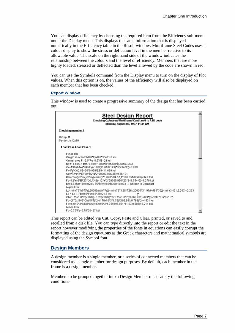
This window is used to create a progressive summary of the design that has been carried out.
This report can be edited via Cut, Copy, Paste and Clear, printed, or saved to and recalled from a disk file. You can type directly into the report or edit the text in the report however modifying the properties of the fonts in equations can easily corrupt the formatting of the design equations as the Greek characters and mathematical symbols are displayed using the Symbol font.
Design Members
A design member is a single member, or a series of connected members that can be considered as a single member for design purposes. By default, each member in the frame is a design member. Members to be grouped together into a Design Member must satisfy the following conditions-
Chapter One Introduction
8
All members must have the same section type
All members must have the same orientation
All members must be rigidly connected internally (ends may be released)
All members must be approximately co-linear
All members must be connected with the local x’ axis facing the same direction
Members may have rigid offsets at internal joints but the flexible portions of the
members must be continuous within the design group.
There must not be any restraints on the internal connecting nodes
Viewing Results Using Design Members
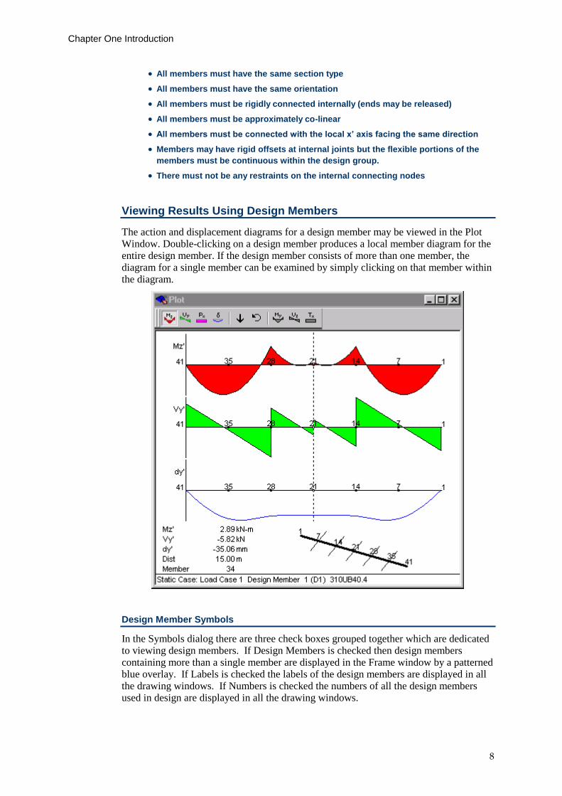
The action and displacement diagrams for a design member may be viewed in the Plot Window. Double-clicking on a design member produces a local member diagram for the entire design member. If the design member consists of more than one member, the diagram for a single member can be examined by simply clicking on that member within the diagram.
Design Member Symbols
In the Symbols dialog there are three check boxes grouped together which are dedicated to viewing design members. If Design Members is checked then design members containing more than a single member are displayed in the Frame window by a patterned blue overlay. If Labels is checked the labels of the design members are displayed in all the drawing windows. If Numbers is checked the numbers of all the design members used in design are displayed in all the drawing windows.
Chapter One Introduction
Page 9
Rendering Design Members
Design members are rendered in the Frame and Load windows as a single member.
Coordinate Systems
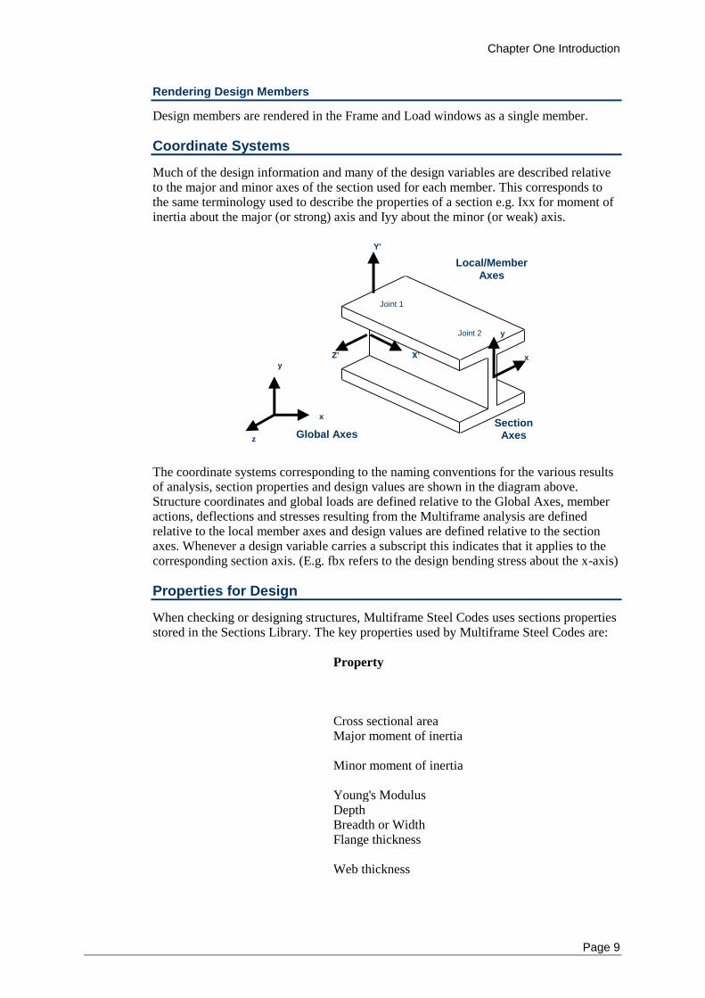
Much of the design information and many of the design variables are described relative to the major and minor axes of the section used for each member. This corresponds to the same terminology used to describe the properties of a section e.g. Ixx for moment of inertia about the major (or strong) axis and Iyy about the minor (or weak) axis.
X’
Y’
Z’
x
y
z Global Axes
Local/Member
Axes
Joint 1
Joint 2
Section Axes
x
y
The coordinate systems corresponding to the naming conventions for the various results of analysis, section properties and design values are shown in the diagram above. Structure coordinates and global loads are defined relative to the Global Axes, member actions, deflections and stresses resulting from the Multiframe analysis are defined relative to the local member axes and design values are defined relative to the section axes. Whenever a design variable carries a subscript this indicates that it applies to the corresponding section axis. (E.g. fbx refers to the design bending stress about the x-axis)
Properties for Design
When checking or designing structures, Multiframe Steel Codes uses sections properties stored in the Sections Library. The key properties used by Multiframe Steel Codes are:
N
a
m
e
Property
A Cross sectional area Ix
Major moment of inertia
Iy
Minor moment of inertia
E Young's Modulus D Depth B Breadth or Width tf
Flange thickness
tw
Web thickness
Chapter One Introduction
10
rx
Major radius of gyration
ry
Minor radius of gyration
rz
Radius of gyration about weakest axis
Sx
Plastic modulus about major axis
Sy
Plastic modulus about minor axis
When you add a section to the Sections Library you must ensure that all of the properties above are correctly entered and are all non-zero.
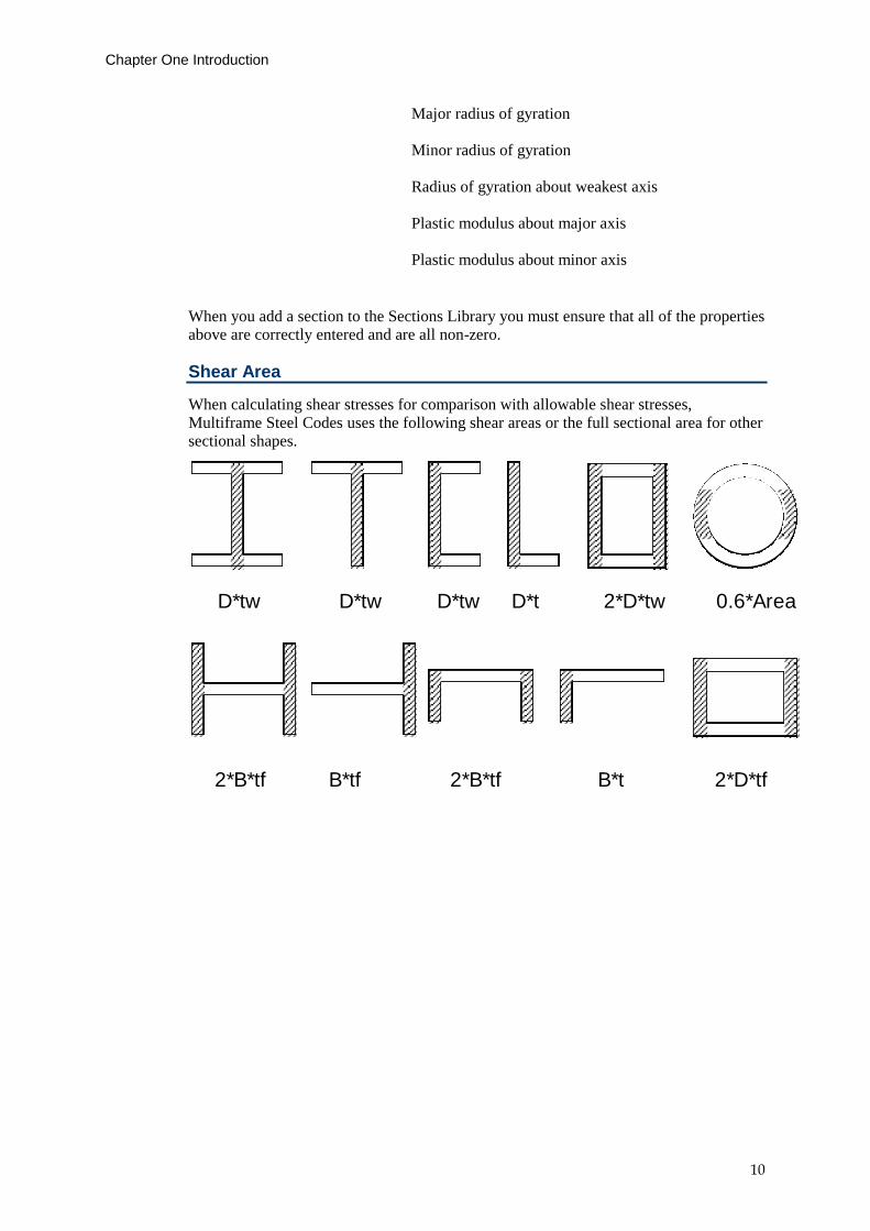
Shear Area
When calculating shear stresses for comparison with allowable shear stresses, Multiframe Steel Codes uses the following shear areas or the full sectional area for other sectional shapes.
D*tw D*tw D*tw D*t 2*D*tw 0.6*Area
2*B*tf B*tf 2*B*tf B*t 2*D*tf
Chapter Two Using Steel Designer
Page 11
Chapter 2 Using Multiframe Steel Codes
This chapter describes how to use Multiframe Steel Codes with step-by-step instructions on the basics of using the program in the following sections:
Design Procedure
Working with Design Members
Setting Design Properties
Setting Design Properties
Setting Section Type
Setting Steel Grade
Setting Design Constraints
Setting Section Constraints
Setting Frame Type
Setting Allowable Stresses
Setting Acceptance Ratio
Setting Capacity Factors
Checking a Frame
Designing a Frame
Printing
Saving your Work
Saving the report
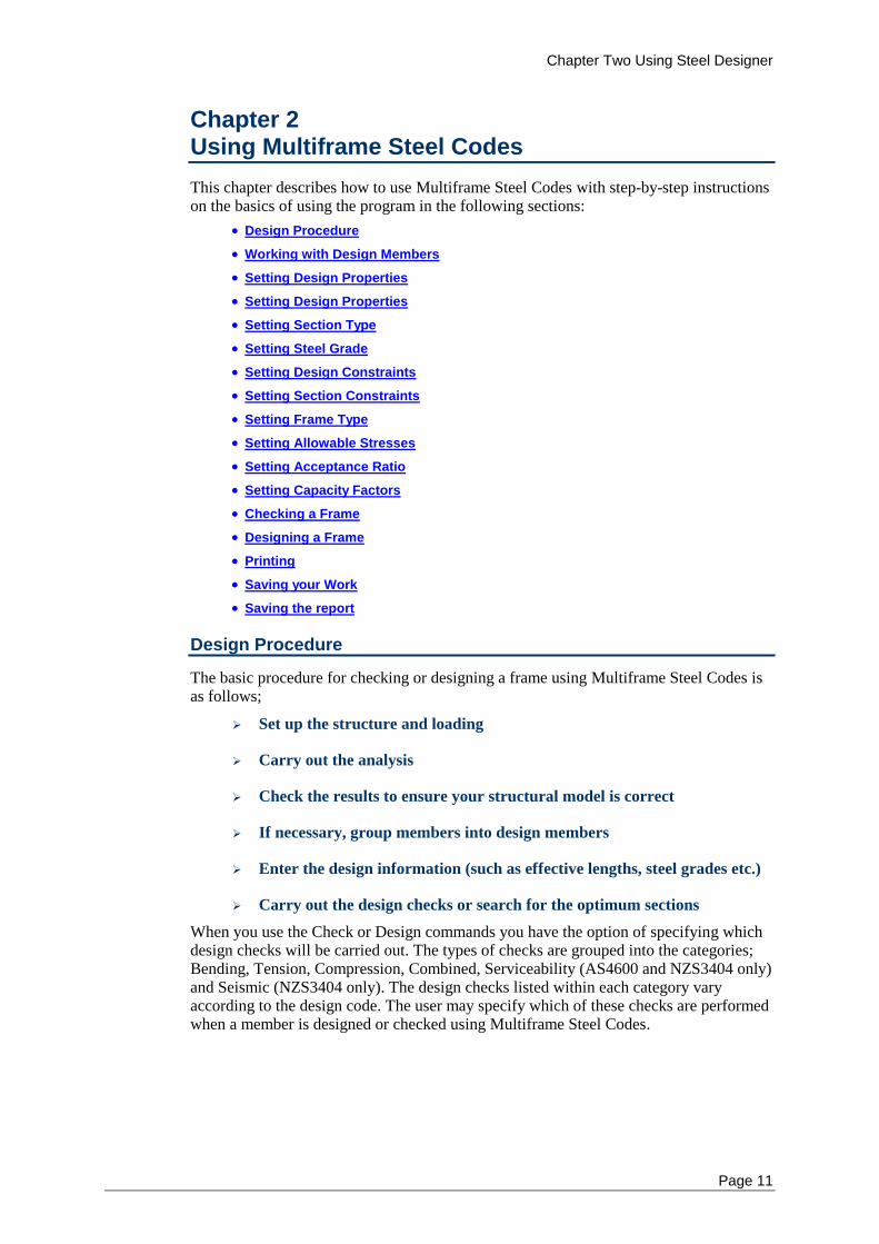
Design Procedure
The basic procedure for checking or designing a frame using Multiframe Steel Codes is as follows;
Set up the structure and loading
Carry out the analysis
Check the results to ensure your structural model is correct
If necessary, group members into design members
Enter the design information (such as effective lengths, steel grades etc.)
Carry out the design checks or search for the optimum sections
When you use the Check or Design commands you have the option of specifying which design checks will be carried out. The types of checks are grouped into the categories; Bending, Tension, Compression, Combined, Serviceability (AS4600 and NZS3404 only) and Seismic (NZS3404 only). The design checks listed within each category vary according to the design code. The user may specify which of these checks are performed when a member is designed or checked using Multiframe Steel Codes.
Chapter Two Using Steel Designer
12
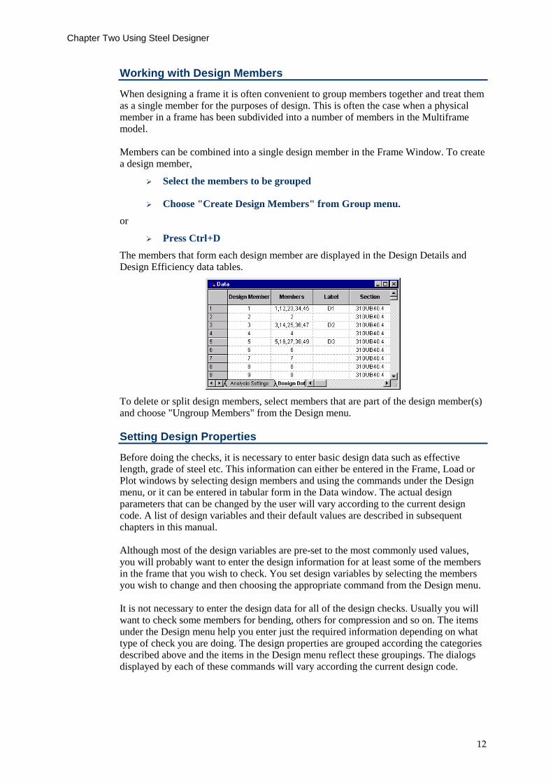
Working with Design Members
When designing a frame it is often convenient to group members together and treat them as a single member for the purposes of design. This is often the case when a physical member in a frame has been subdivided into a number of members in the Multiframe model. Members can be combined into a single design member in the Frame Window. To create a design member,
Select the members to be grouped
Choose "Create Design Members" from Group menu.
or
Press Ctrl+D
The members that form each design member are displayed in the Design Details and Design Efficiency data tables.
To delete or split design members, select members that are part of the design member(s) and choose "Ungroup Members" from the Design menu.
Setting Design Properties
Before doing the checks, it is necessary to enter basic design data such as effective length, grade of steel etc. This information can either be entered in the Frame, Load or Plot windows by selecting design members and using the commands under the Design menu, or it can be entered in tabular form in the Data window. The actual design parameters that can be changed by the user will vary according to the current design code. A list of design variables and their default values are described in subsequent chapters in this manual. Although most of the design variables are pre-set to the most commonly used values, you will probably want to enter the design information for at least some of the members in the frame that you wish to check. You set design variables by selecting the members you wish to change and then choosing the appropriate command from the Design menu. It is not necessary to enter the design data for all of the design checks. Usually you will want to check some members for bending, others for compression and so on. The items under the Design menu help you enter just the required information depending on what type of check you are doing. The design properties are grouped according the categories described above and the items in the Design menu reflect these groupings. The dialogs displayed by each of these commands will vary according the current design code.
Chapter Two Using Steel Designer
Page 13
Bending
When performing a bending check, you may need to specify a number of properties relating to the unbraced length, location and type of lateral restraints, and the stiffener spacing on the member.
Tension
Tension checks usually require the user to specify the area of holes in the cross section and a coefficient to account for the distribution of end forces or used to computing effective net area of the section.
Compression
When checking or designing members for compression, it is necessary to specify the effective length and unbraced length of the member.
Combined Actions
Some design codes require the user to specify a coefficient that accounts for the distribution of moments along a member.
Serviceability
With some design codes, it may be necessary to specify the deflection limits used in checking the serviceability of a member.
Seismic
Some design codes require a member to be categorised according to the required ductility of the member.
For some design codes, no design data is required for the design checks in a particular category and so the menu item will not be enabled. In other codes, there are no design checks performed within a particular category and the menu item will again be disabled.
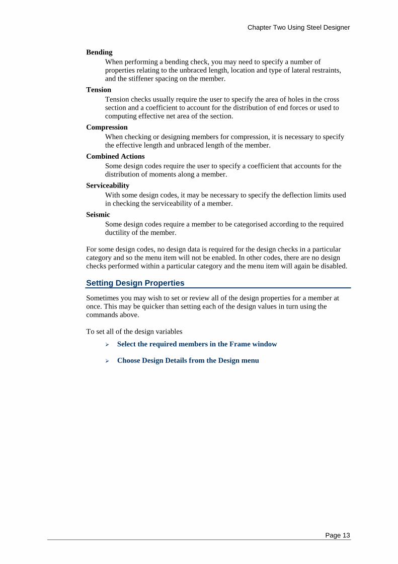
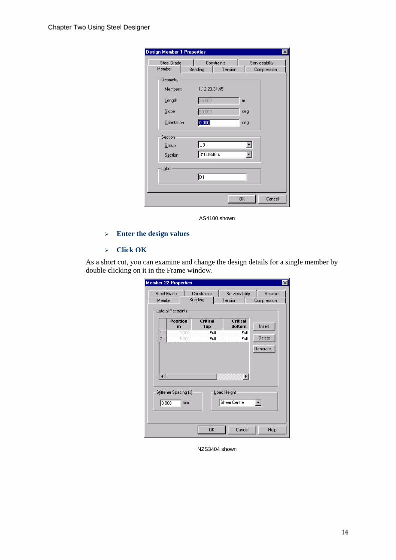
Setting Design Properties
Sometimes you may wish to set or review all of the design properties for a member at once. This may be quicker than setting each of the design values in turn using the commands above. To set all of the design variables
Select the required members in the Frame window
Choose Design Details from the Design menu
Chapter Two Using Steel Designer
14
AS4100 shown
Enter the design values
Click OK
As a short cut, you can examine and change the design details for a single member by double clicking on it in the Frame window.
NZS3404 shown
Chapter Two Using Steel Designer
Page 15
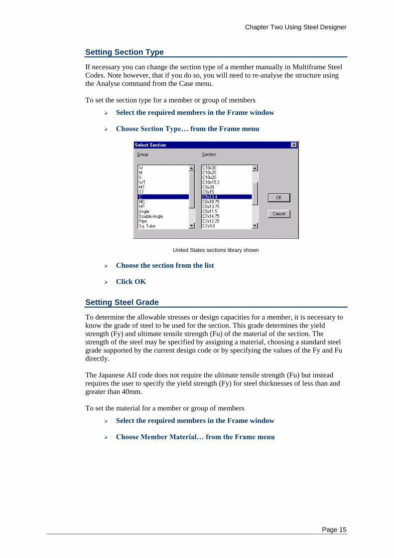
Setting Section Type
If necessary you can change the section type of a member manually in Multiframe Steel Codes. Note however, that if you do so, you will need to re-analyse the structure using the Analyse command from the Case menu. To set the section type for a member or group of members
Select the required members in the Frame window
Choose Section Type… from the Frame menu
United States sections library shown
Choose the section from the list
Click OK
Setting Steel Grade
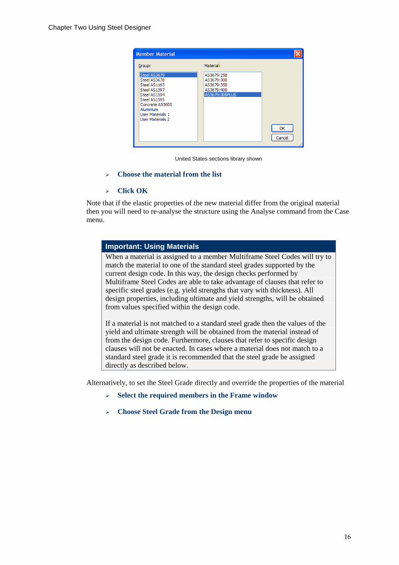
To determine the allowable stresses or design capacities for a member, it is necessary to know the grade of steel to be used for the section. This grade determines the yield strength (Fy) and ultimate tensile strength (Fu) of the material of the section. The strength of the steel may be specified by assigning a material, choosing a standard steel grade supported by the current design code or by specifying the values of the Fy and Fu directly. The Japanese AIJ code does not require the ultimate tensile strength (Fu) but instead requires the user to specify the yield strength (Fy) for steel thicknesses of less than and greater than 40mm. To set the material for a member or group of members
Select the required members in the Frame window
Choose Member Material… from the Frame menu
Chapter Two Using Steel Designer
16
United States sections library shown
Choose the material from the list
Click OK
Note that if the elastic properties of the new material differ from the original material then you will need to re-analyse the structure using the Analyse command from the Case menu.
Important: Using Materials
When a material is assigned to a member Multiframe Steel Codes will try to match the material to one of the standard steel grades supported by the current design code. In this way, the design checks performed by Multiframe Steel Codes are able to take advantage of clauses that refer to specific steel grades (e.g. yield strengths that vary with thickness). All design properties, including ultimate and yield strengths, will be obtained from values specified within the design code.
If a material is not matched to a standard steel grade then the values of the yield and ultimate strength will be obtained from the material instead of from the design code. Furthermore, clauses that refer to specific design clauses will not be enacted. In cases where a material does not match to a standard steel grade it is recommended that the steel grade be assigned directly as described below.
Alternatively, to set the Steel Grade directly and override the properties of the material
Select the required members in the Frame window
Choose Steel Grade from the Design menu
Chapter Two Using Steel Designer
Page 17
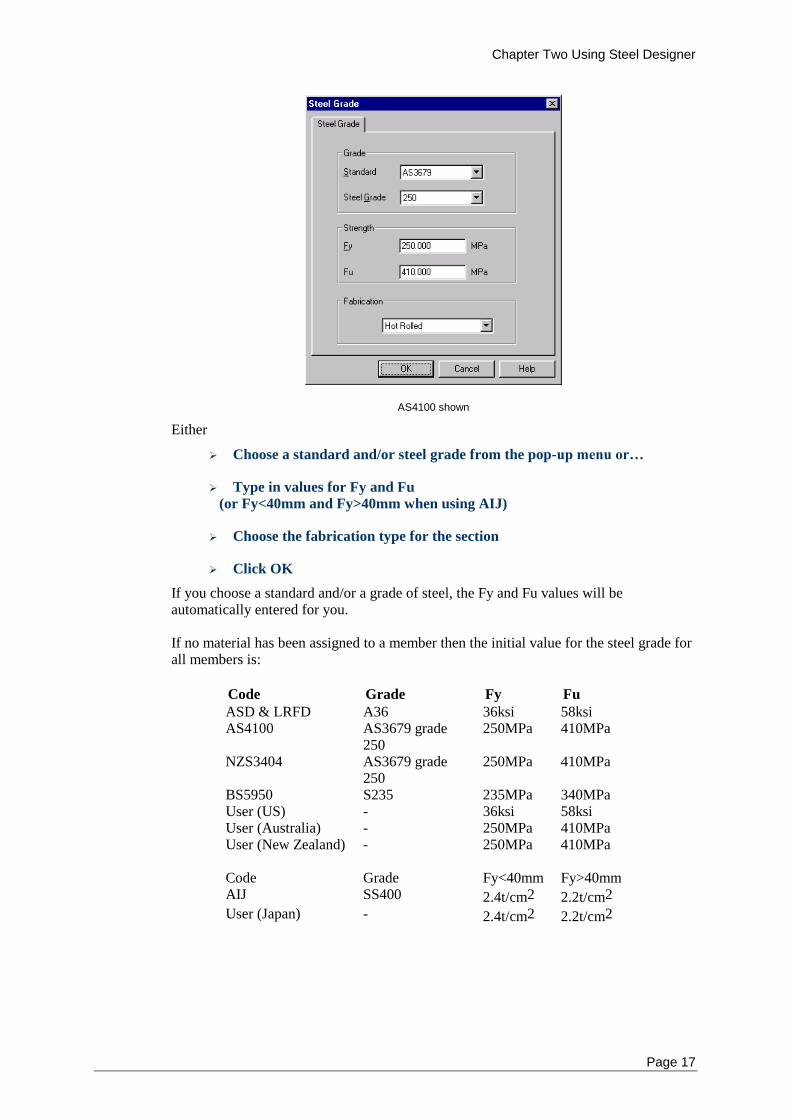
AS4100 shown
Either
Choose a standard and/or steel grade from the pop-up menu or…
Type in values for Fy and Fu
(or Fy<40mm and Fy>40mm when using AIJ)
Choose the fabrication type for the section
Click OK
If you choose a standard and/or a grade of steel, the Fy and Fu values will be automatically entered for you. If no material has been assigned to a member then the initial value for the steel grade for all members is:
Code Grade Fy Fu
ASD & LRFD A36 36ksi 58ksi AS4100 AS3679 grade
250 250MPa 410MPa
NZS3404 AS3679 grade 250
250MPa 410MPa
BS5950 S235 235MPa 340MPa User (US) - 36ksi 58ksi User (Australia) - 250MPa 410MPa User (New Zealand) - 250MPa 410MPa
Code Grade Fy<40mm Fy>40mm AIJ SS400 2.4t/cm2 2.2t/cm2
User (Japan) - 2.4t/cm2 2.2t/cm2
Chapter Two Using Steel Designer
18
Setting Design Constraints
Steel Design uses the concept of Design Constraints to describe any design requirements that are not dependent upon the design actions and can be tested independently of the load cases. Design Constraints include constraints that may be imposed by the designer upon the dimensions of a member as well as any constraints that may be imposed by various design checks. (i.e. a slenderness check that may be required as part of a bending design). Design Constraints are applied when Designing and Checking a member. The calculations associated with Design Constraints are output to the design report. These calculations are performed at the start of the design before considering the design checks for each load case. When using Brief Reporting, the calculations for failed design constraints are output to the report. With detailed or full reporting, the calculations for all Design Constraints are shown in the report. The status of Design Constraints which were tested when Designing or Checking a member are displayed in the "Constraints" column in the Design Efficiency table. If no constraints were checked for a particular member, a dash is shown is this column. Otherwise, this column displays the number of Design Constraints that were not satisfied as part of the design checks.
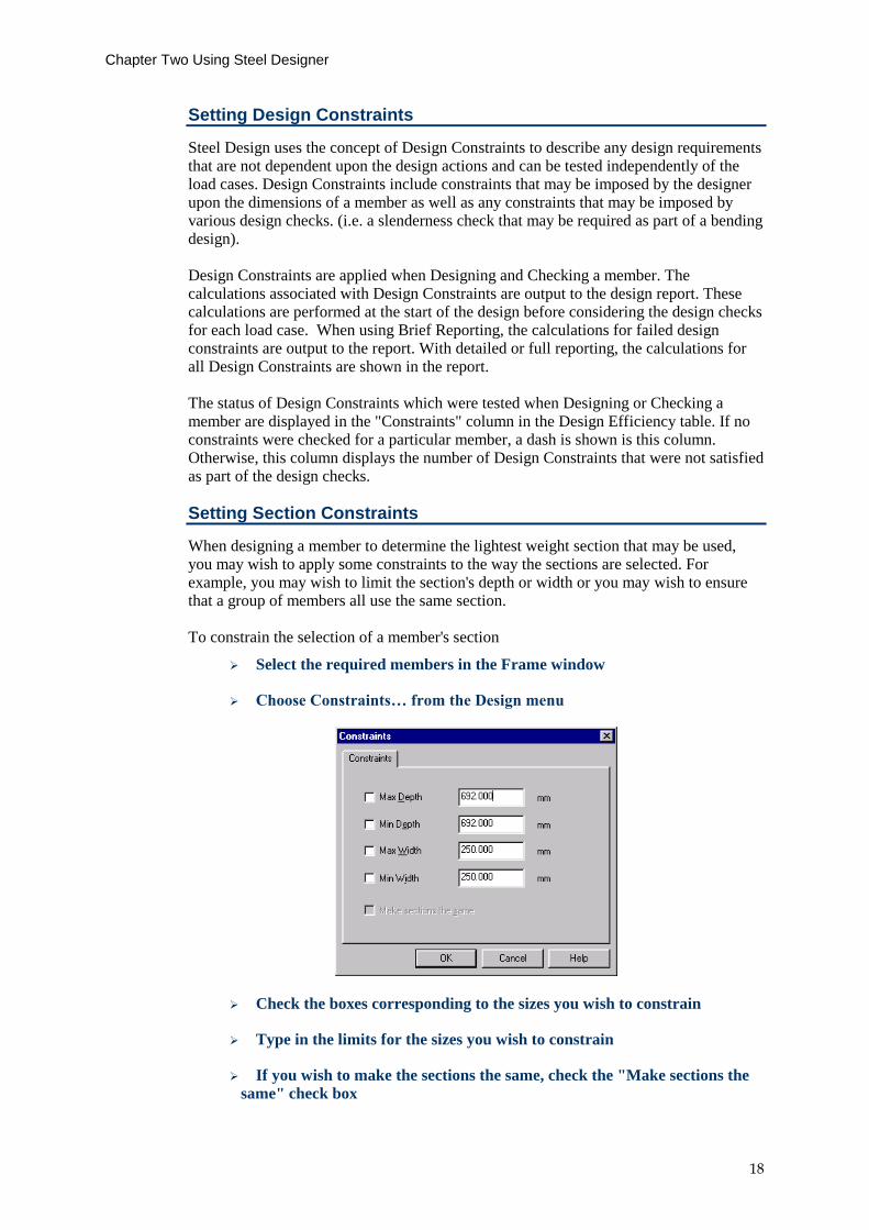
Setting Section Constraints
When designing a member to determine the lightest weight section that may be used, you may wish to apply some constraints to the way the sections are selected. For example, you may wish to limit the section's depth or width or you may wish to ensure that a group of members all use the same section. To constrain the selection of a member's section
Select the required members in the Frame window
Choose Constraints… from the Design menu
Check the boxes corresponding to the sizes you wish to constrain
Type in the limits for the sizes you wish to constrain
If you wish to make the sections the same, check the "Make sections the
same" check box
Chapter Two Using Steel Designer
Page 19
Click OK
The initial value of constraints is for no limits on the sizes of sections and all members are free to be designed using a different section.
Variable
Name
Description Default
Max Depth
The maximum depth of section which may be chosen when using the Design command
Depth of the initial section
Min Depth
The minimum depth of section which may be chosen when using the Design command
Depth of the initial section
Max Width
The maximum width of section which may be chosen when using the Design command
Width of the initial section
Min Width
The minimum width of section which may be chosen when using the Design command
Width of the initial section
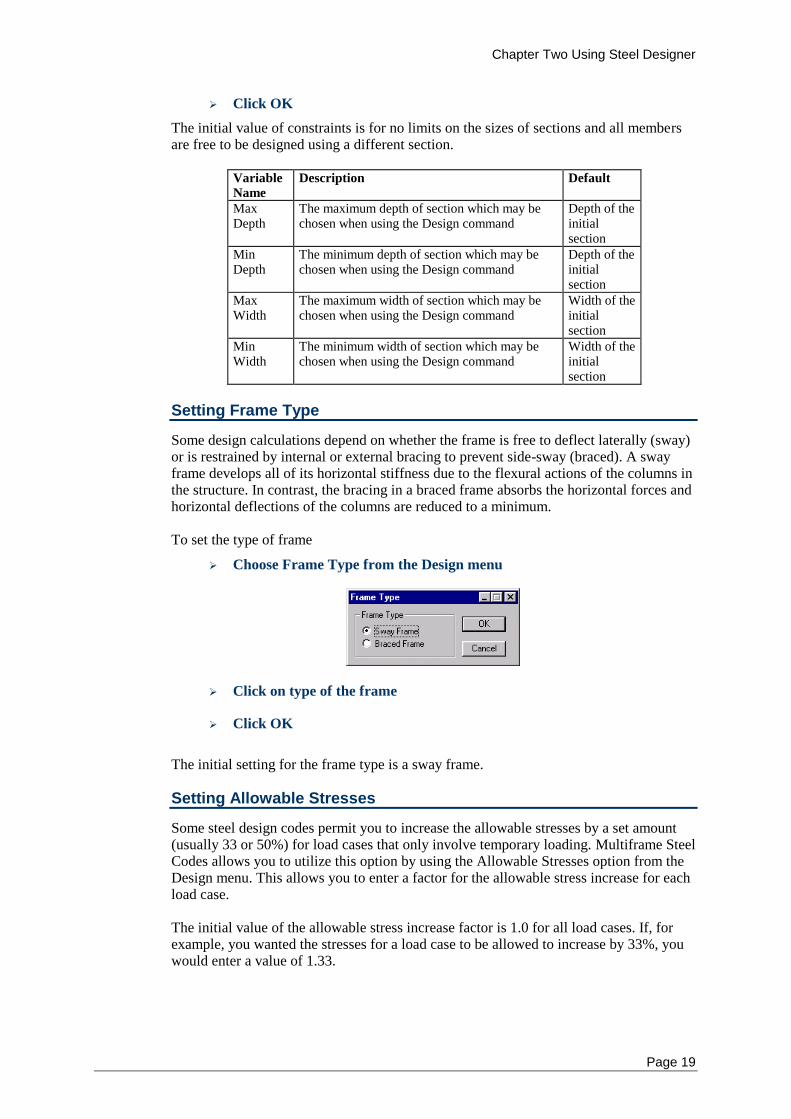
Setting Frame Type
Some design calculations depend on whether the frame is free to deflect laterally (sway) or is restrained by internal or external bracing to prevent side-sway (braced). A sway frame develops all of its horizontal stiffness due to the flexural actions of the columns in the structure. In contrast, the bracing in a braced frame absorbs the horizontal forces and horizontal deflections of the columns are reduced to a minimum. To set the type of frame
Choose Frame Type from the Design menu
Click on type of the frame
Click OK
The initial setting for the frame type is a sway frame.
Setting Allowable Stresses
Some steel design codes permit you to increase the allowable stresses by a set amount (usually 33 or 50%) for load cases that only involve temporary loading. Multiframe Steel Codes allows you to utilize this option by using the Allowable Stresses option from the Design menu. This allows you to enter a factor for the allowable stress increase for each load case. The initial value of the allowable stress increase factor is 1.0 for all load cases. If, for example, you wanted the stresses for a load case to be allowed to increase by 33%, you would enter a value of 1.33.
Chapter Two Using Steel Designer
20
Setting Acceptance Ratio
Some of the design codes within Multiframe Steel Codes allow the user to modify the value of the efficiency below which the design checks on a member have deemed to of passed. This value is known as the Acceptance Ratio. Any design check on the member for which the efficiency exceed this value will be marked as a failed check. The Acceptance ratio for a particular member is set via the Options command in the Design menu. The initial value of the Acceptance Ratio for all members is 100%.
Setting Capacity Factors
In limit state design the design capacity is obtained by multiplying the nominal capacity by the capacity factor. The capacity factor will vary depending upon the specific design check being considered. The design codes generally specify maximum values for the capacity factors. In some circumstances the user may wish to specify other values for the capacity. Multiframe Steel Codes allows you to do this by using the Capacity Factors option from the Design menu. A dialog is displayed which allows the user to change the capacity factors for each of the design checks for a strength limit state. The initial values of the capacity factors are the values specified by the design codes. In most likely that the capacity factors will never be modified by a user.
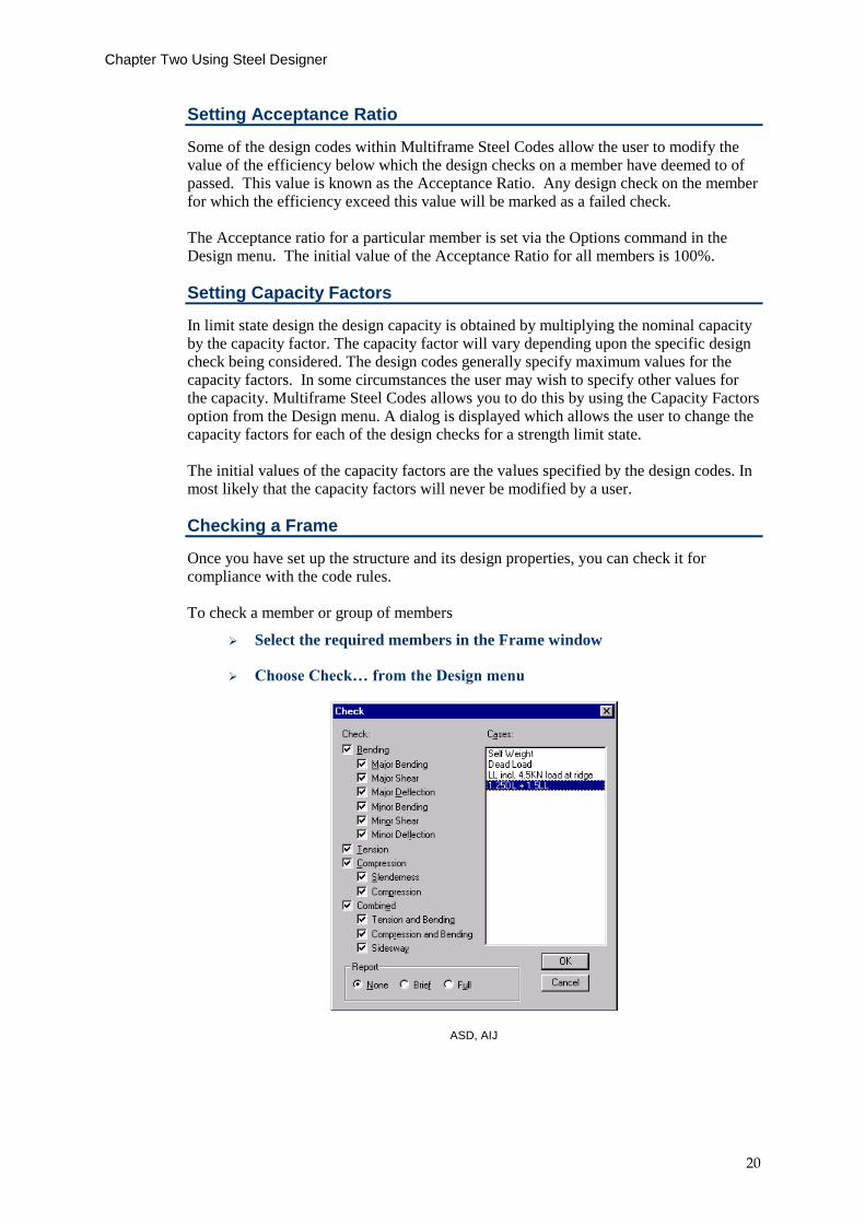
Checking a Frame
Once you have set up the structure and its design properties, you can check it for compliance with the code rules. To check a member or group of members
Select the required members in the Frame window
Choose Check… from the Design menu
ASD, AIJ
Chapter Two Using Steel Designer
Page 21
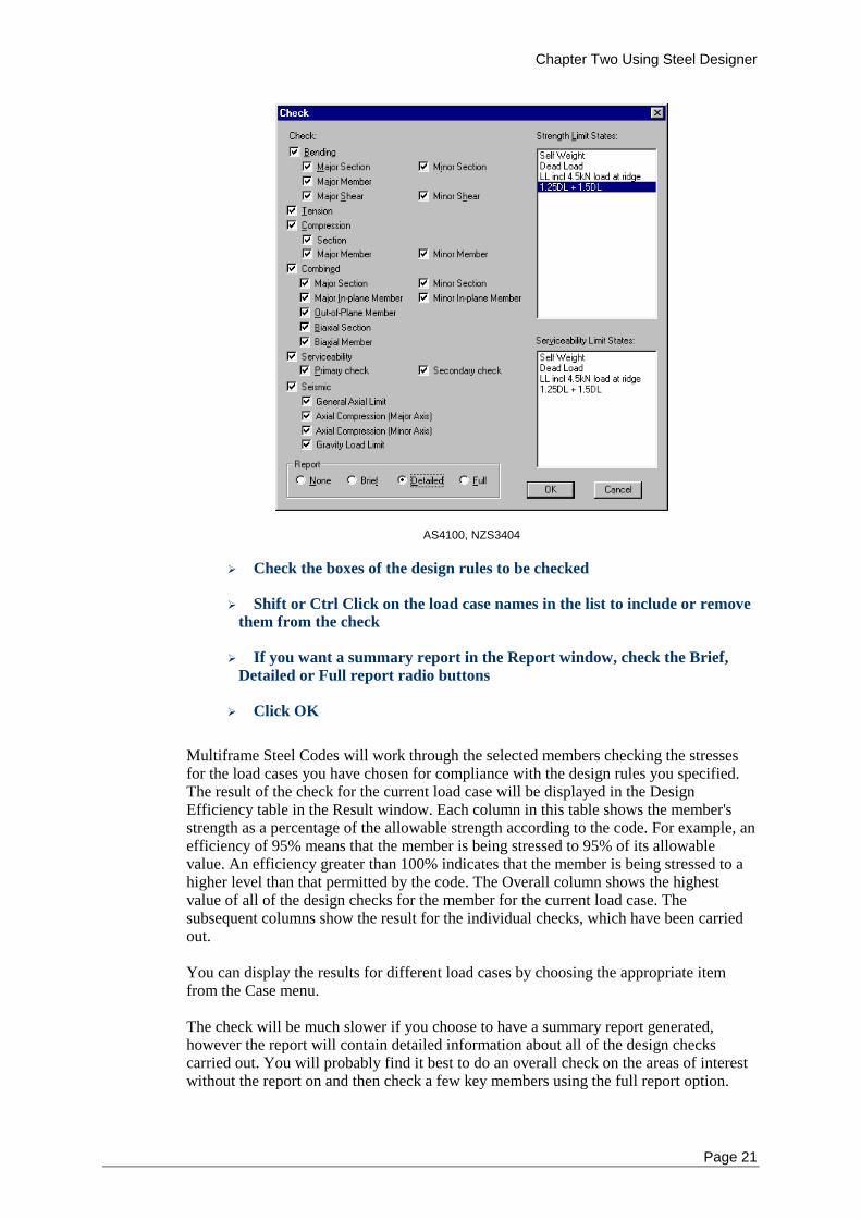
AS4100, NZS3404
Check the boxes of the design rules to be checked
Shift or Ctrl Click on the load case names in the list to include or remove
them from the check
If you want a summary report in the Report window, check the Brief,
Detailed or Full report radio buttons
Click OK
Multiframe Steel Codes will work through the selected members checking the stresses for the load cases you have chosen for compliance with the design rules you specified. The result of the check for the current load case will be displayed in the Design Efficiency table in the Result window. Each column in this table shows the member's strength as a percentage of the allowable strength according to the code. For example, an efficiency of 95% means that the member is being stressed to 95% of its allowable value. An efficiency greater than 100% indicates that the member is being stressed to a higher level than that permitted by the code. The Overall column shows the highest value of all of the design checks for the member for the current load case. The subsequent columns show the result for the individual checks, which have been carried out. You can display the results for different load cases by choosing the appropriate item from the Case menu. The check will be much slower if you choose to have a summary report generated, however the report will contain detailed information about all of the design checks carried out. You will probably find it best to do an overall check on the areas of interest without the report on and then check a few key members using the full report option.
Chapter Two Using Steel Designer
22
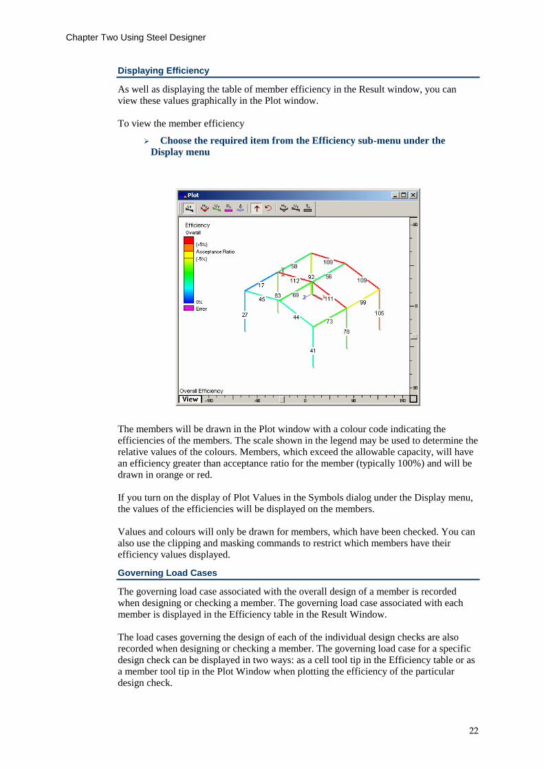
Displaying Efficiency
As well as displaying the table of member efficiency in the Result window, you can view these values graphically in the Plot window. To view the member efficiency
Choose the required item from the Efficiency sub-menu under the
Display menu
The members will be drawn in the Plot window with a colour code indicating the efficiencies of the members. The scale shown in the legend may be used to determine the relative values of the colours. Members, which exceed the allowable capacity, will have an efficiency greater than acceptance ratio for the member (typically 100%) and will be drawn in orange or red. If you turn on the display of Plot Values in the Symbols dialog under the Display menu, the values of the efficiencies will be displayed on the members. Values and colours will only be drawn for members, which have been checked. You can also use the clipping and masking commands to restrict which members have their efficiency values displayed.
Governing Load Cases
The governing load case associated with the overall design of a member is recorded when designing or checking a member. The governing load case associated with each member is displayed in the Efficiency table in the Result Window. The load cases governing the design of each of the individual design checks are also recorded when designing or checking a member. The governing load case for a specific design check can be displayed in two ways: as a cell tool tip in the Efficiency table or as a member tool tip in the Plot Window when plotting the efficiency of the particular design check.
Chapter Two Using Steel Designer
Page 23
Designing a Frame
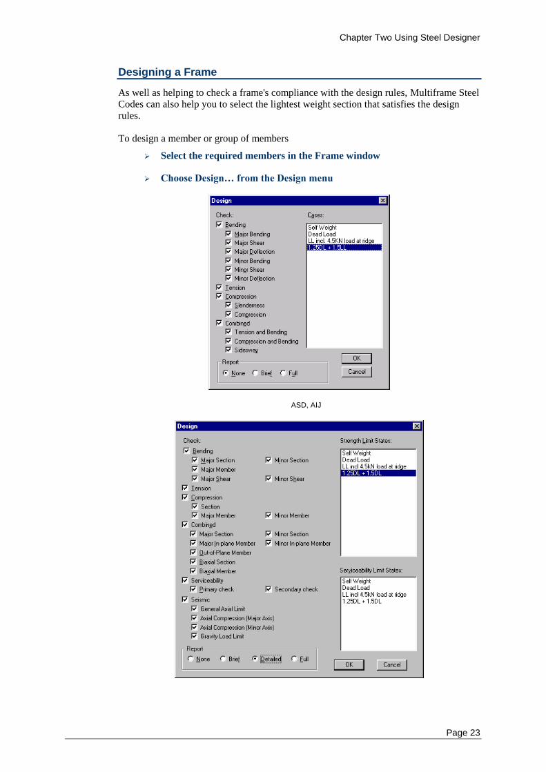
As well as helping to check a frame's compliance with the design rules, Multiframe Steel Codes can also help you to select the lightest weight section that satisfies the design rules. To design a member or group of members
Select the required members in the Frame window
Choose Design… from the Design menu
ASD, AIJ
Chapter Two Using Steel Designer
24
AS4100, NZS3404
Check the boxes of the design rules to be used when designing
Shift-Click on the load case names in the list to include or remove them
from the check
If you want a summary report in the Report window, check the Brief or
Full report radio buttons
Click OK
Multiframe Steel Codes will design each of the selected members; searching through the group of sections the member's original section comes from, to find the lightest section in this group that meets the design rule requirements. Once the design has finished, you can view the optimum section in the Best Section column in the Member Efficiency table in the Result window. If you want to automatically assign all of the optimum sections to their respective members, you can use the Use Best Sections command from the Design menu to do this. Because changing the sections will change the results of the analysis, you will have to re-analyse the structure after doing this. You may find it useful to wait until you have designed all of the members you wish to optimise before using the Use Best Sections command.
Optimum Sections
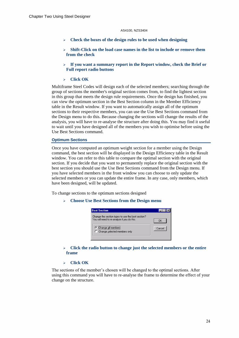
Once you have computed an optimum weight section for a member using the Design command, the best section will be displayed in the Design Efficiency table in the Result window. You can refer to this table to compare the optimal section with the original section. If you decide that you want to permanently replace the original section with the best section you should use the Use Best Sections command from the Design menu. If you have selected members in the front window you can choose to only update the selected members or you can update the entire frame. In any case, only members, which have been designed, will be updated. To change sections to the optimum sections designed
Choose Use Best Sections from the Design menu
Click the radio button to change just the selected members or the entire
frame
Click OK
The sections of the member’s chosen will be changed to the optimal sections. After using this command you will have to re-analyse the frame to determine the effect of your change on the structure.
Chapter Two Using Steel Designer
Page 25
The user can override the design and specify the optimal section for a member using the command from the Design menu in which case the select section dialog will be displayed. As this command does not invalidate the results of analyses it can be used to temporarily store the next section shape to be allocated to a member. In this way other members in the frame can be investigated before having to reanalyses the structure.
Tips On Optimisation
When you use the Design command, Multiframe Steel Codes will try to find the lightest weight section in a member's group, which will satisfy the design requirements. If there are a large number of sections in the group, this may take some time. If you use the options to constrain the width or depth of the optimum section, Multiframe Steel Codes will automatically skip the check for any sections, which don't satisfy these criteria. This means you can speed up the optimisation greatly by specifying constraints for the size of the section. For example, if you are selecting an optimum section from the W sections in the United States Section Library which contains a large number of sections, specifying an upper and lower bound for the depth will let Multiframe Steel Codes automatically skip most of the sections and quickly find one of the right size. Checking for sway when using the Design command is not recommended. It is unlikely that Multiframe Steel Codes will find an optimum size member because the amount of sway is likely due to the stiffness of other members (probably the columns in another part of the frame) rather than the member under consideration. These other members will not be changed while the current member is being checked.
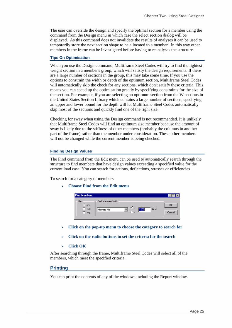
Finding Design Values
The Find command from the Edit menu can be used to automatically search through the structure to find members that have design values exceeding a specified value for the current load case. You can search for actions, deflections, stresses or efficiencies. To search for a category of members
Choose Find from the Edit menu
Click on the pop-up menu to choose the category to search for
Click on the radio buttons to set the criteria for the search
Click OK
After searching through the frame, Multiframe Steel Codes will select all of the members, which meet the specified criteria.
Printing
You can print the contents of any of the windows including the Report window.
Chapter Two Using Steel Designer
26
Printing the Report Window
To print the contents of the Report window
Ensure the Report window is in front
Choose Print Window from the File menu
As with the other windows in Multiframe, the user may review the output in the Print Preview before sending the output to the printer.
Saving your Work
You can save your design work at any time and then open the frame later to continue where you left off. To save the frame and its design information to disk
Choose Save from the File menu
The frame will be saved to disk complete with the design information you added to it.
Saving the report
You can also save the report to disk and recall it at a later date. To save the report to disk
Ensure the Report window is in front
Choose Save from the File menu
The report will be saved to disk. Use the Open command to read the report in again. If you need to transfer the data in the report to another program like Microsoft Word, use the Select All and Copy and Paste command to paste the data into the other program. Multiframe Steel Codes places the report data on the clipboard in the RTF (Rich Text) format.
Chapter Three ASD and AIJ
Page 27
Chapter 3 ASD and AIJ
This chapter describes the implementation of the ASD and AIJ steel design codes within Multiframe Steel Codes. It provides a step-by-step description of how to modify the design properties used by each code.
Design Checks
Bending
Tension
Compression
Combined Actions
Default Design Properties
Code Clauses Checked
Design Checks - ASD and AIJ
The design checks performed using the ASD and AIJ codes are grouped into the four categories; Bending, Tension, Compression, and Combined.
Bending - ASD and AIJ
There are six design checks grouped under the Bending category. These checks verify a member's capacity to resist bending moments and shear forces about the major and minor axes. Design checks for the deflection of the member are also included in this group. When performing a bending check, you need to specify a number of properties relating to the unbraced length and the spacing of stiffeners on the member. When using the ASD code, the user may also specify a bending coefficient.
Design Constraints (AIJ)
When checking or designing a member for bending, compression or combined bending and compression, a design constraint is automatically imposed by Multiframe Steel Codes. This constraint verifies that the member satisfies the requirements of AIJ for the Width to Thickness Ratio (b/t) of Plate Elements.
Unbraced Length - ASD and AIJ
To determine the critical buckling condition of a member, it is necessary to know the spacing of any bracing (if any) along the member. Purlins, girts or other structural elements that are not modelled in Multiframe could provide this bracing. Some bracing may only restrain lateral deflection in one direction. It is therefore necessary to enter unbraced lengths for both axes of the section, Lbx corresponding to the spacing of restraints preventing buckling about the x-x axis and Lby corresponding to the spacing of restraints preventing buckling about the y-y axis. The initial values of Lbx and Lby are the length of the member.
Chapter Three ASD and AIJ
Page 28
Bending Coefficient (ASD)
The ASD code requires a bending coefficient Cb that is either calculated by the program according to the rules in the code, or may be specified by the user. If you leave Cb unchanged, Multiframe Steel Codes will select a value for you, which will be displayed in Italics in the Design Details table in the Data window. This value is most commonly 1.0. If you type in a value, Multiframe Steel Codes will always use this value and display it in non-italic (i.e. standard) text in the Design Details table.
Web Stiffener Spacing - ASD and AIJ
When checking or designing a member for bending, you may need to specify the spacing of any stiffeners along the web of the member. This affects the member’s susceptibility to buckling due to bending. If there are no transverse stiffeners, you should leave the stiffener spacing set to zero.
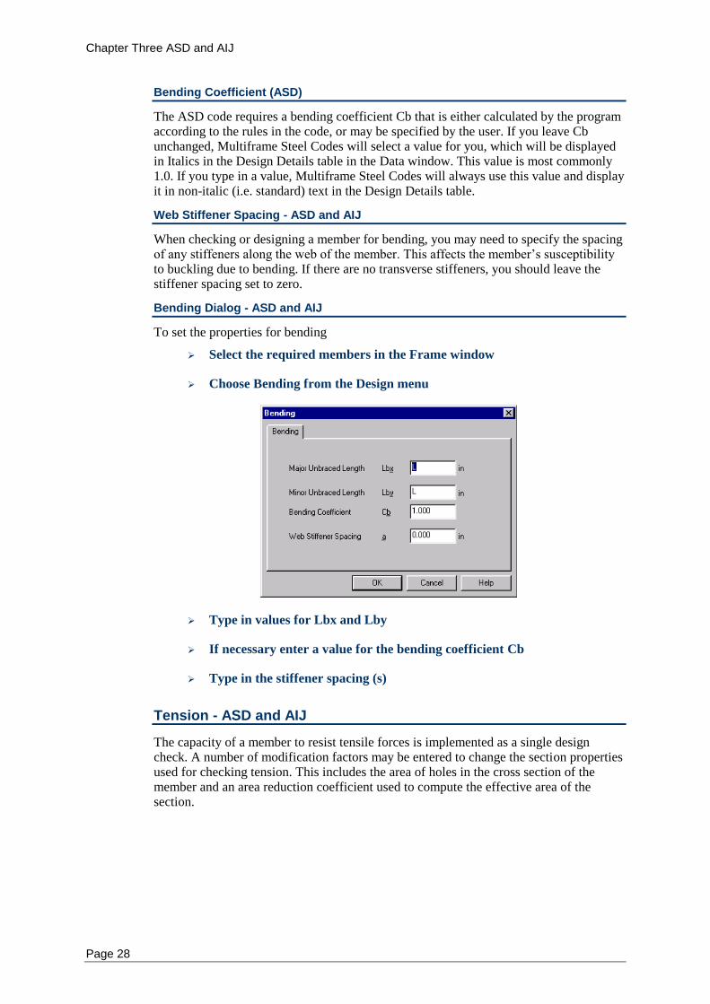
Bending Dialog - ASD and AIJ
To set the properties for bending
Select the required members in the Frame window
Choose Bending from the Design menu
Type in values for Lbx and Lby
If necessary enter a value for the bending coefficient Cb
Type in the stiffener spacing (s)
Tension - ASD and AIJ
The capacity of a member to resist tensile forces is implemented as a single design check. A number of modification factors may be entered to change the section properties used for checking tension. This includes the area of holes in the cross section of the member and an area reduction coefficient used to compute the effective area of the section.
Chapter Three ASD and AIJ
Page 29
Bolt Holes - ASD and AIJ
When checking or designing a member for tension, you need to specify any reduction in area due to boltholes or other reductions. If the members contain significant areas of boltholes, which need to be taken into account when determining the cross-sectional area of the section, you will need to enter the amount of cross-sectional area to be deducted to allow for these holes. The initial value for the area of boltholes is zero. The net area of the section is the gross area minus the combined area of boltholes in the flange and web.
Area Reduction - ASD and AIJ
The net area is multiplied by the area reduction coefficient, U, to give the effective net area of the section. The default value of U is 1.0, i.e. no reduction in area.
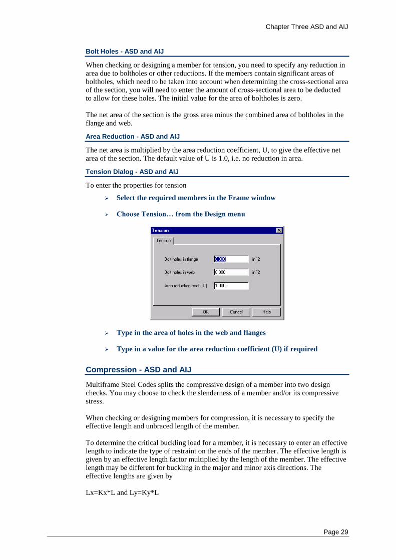
Tension Dialog - ASD and AIJ
To enter the properties for tension
Select the required members in the Frame window
Choose Tension… from the Design menu
Type in the area of holes in the web and flanges
Type in a value for the area reduction coefficient (U) if required
Compression - ASD and AIJ
Multiframe Steel Codes splits the compressive design of a member into two design checks. You may choose to check the slenderness of a member and/or its compressive stress. When checking or designing members for compression, it is necessary to specify the effective length and unbraced length of the member. To determine the critical buckling load for a member, it is necessary to enter an effective length to indicate the type of restraint on the ends of the member. The effective length is given by an effective length factor multiplied by the length of the member. The effective length may be different for buckling in the major and minor axis directions. The effective lengths are given by Lx=Kx*L and Ly=Ky*L
Chapter Three ASD and AIJ
Page 30
Where L is the length of the member and Kx and Ky are the two effective length factors for the major and minor axes respectively. The initial values of Kx and Ky are 1.0. The slenderness is measured as:
Kx*L/rx
Slenderness=Maximum of {
Ky*L/ry
See also: Unbraced Length
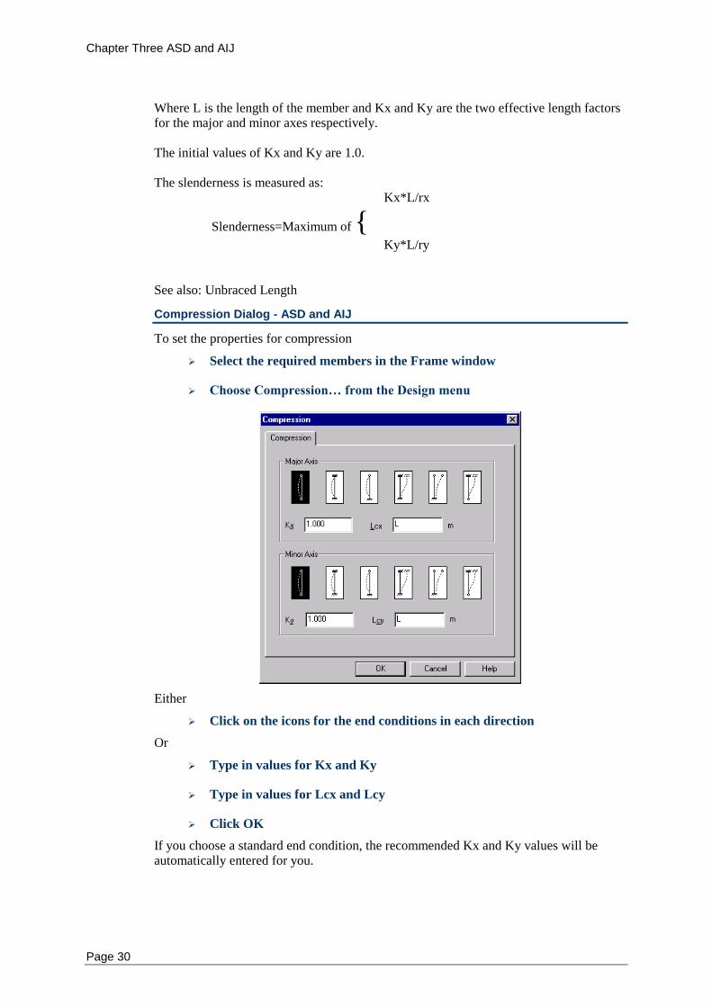
Compression Dialog - ASD and AIJ
To set the properties for compression
Select the required members in the Frame window
Choose Compression… from the Design menu
Either
Click on the icons for the end conditions in each direction
Or
Type in values for Kx and Ky
Type in values for Lcx and Lcy
Click OK
If you choose a standard end condition, the recommended Kx and Ky values will be automatically entered for you.
Chapter Three ASD and AIJ
Page 31
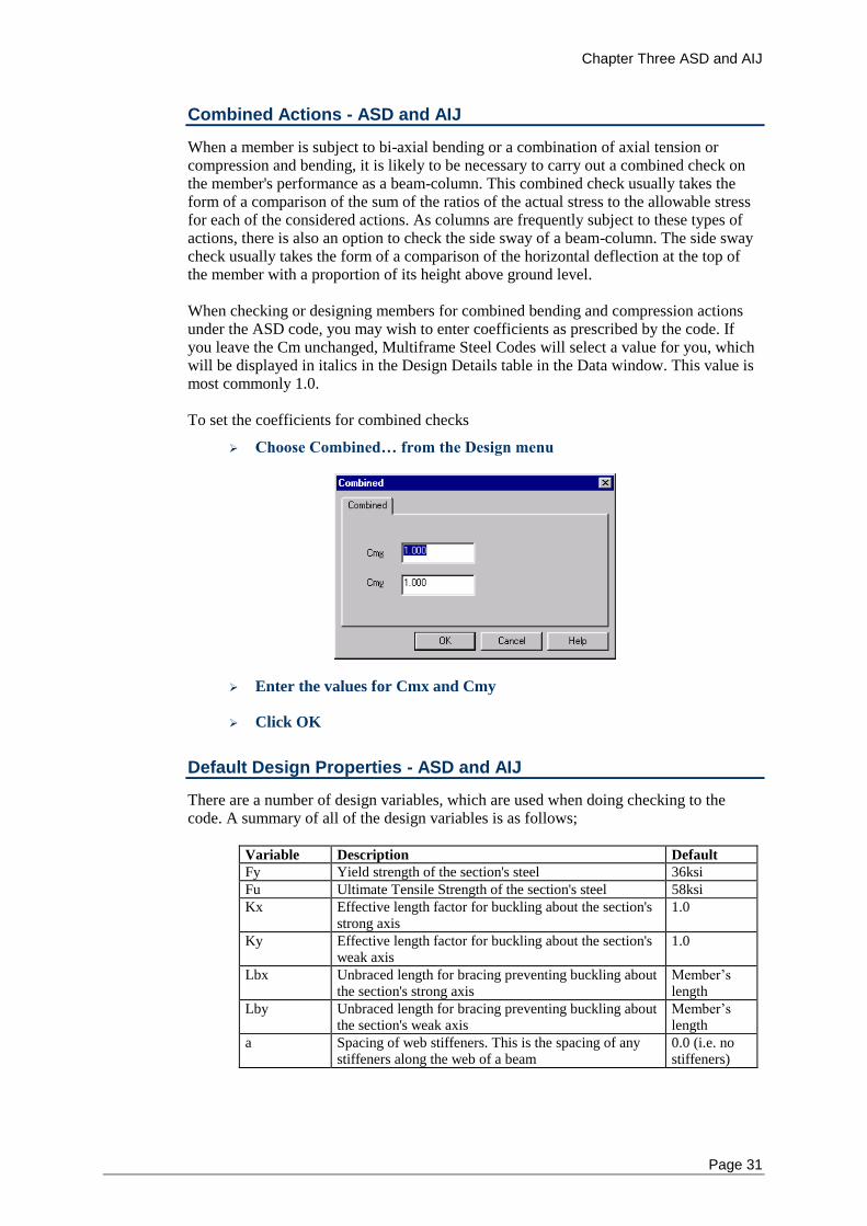
Combined Actions - ASD and AIJ
When a member is subject to bi-axial bending or a combination of axial tension or compression and bending, it is likely to be necessary to carry out a combined check on the member's performance as a beam-column. This combined check usually takes the form of a comparison of the sum of the ratios of the actual stress to the allowable stress for each of the considered actions. As columns are frequently subject to these types of actions, there is also an option to check the side sway of a beam-column. The side sway check usually takes the form of a comparison of the horizontal deflection at the top of the member with a proportion of its height above ground level. When checking or designing members for combined bending and compression actions under the ASD code, you may wish to enter coefficients as prescribed by the code. If you leave the Cm unchanged, Multiframe Steel Codes will select a value for you, which will be displayed in italics in the Design Details table in the Data window. This value is most commonly 1.0. To set the coefficients for combined checks
Choose Combined… from the Design menu
Enter the values for Cmx and Cmy
Click OK
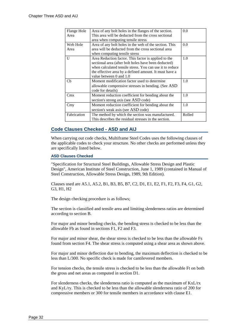
Default Design Properties - ASD and AIJ
There are a number of design variables, which are used when doing checking to the code. A summary of all of the design variables is as follows;
Variable Description Default
Fy Yield strength of the section's steel 36ksi
Fu Ultimate Tensile Strength of the section's steel 58ksi
Kx Effective length factor for buckling about the section's strong axis
1.0
Ky Effective length factor for buckling about the section's weak axis
1.0
Lbx Unbraced length for bracing preventing buckling about the section's strong axis
Member’s length
Lby Unbraced length for bracing preventing buckling about the section's weak axis
Member’s length
a Spacing of web stiffeners. This is the spacing of any stiffeners along the web of a beam
0.0 (i.e. no stiffeners)
Chapter Three ASD and AIJ
Page 32
Flange Hole Area
Area of any bolt holes in the flanges of the section. This area will be deducted from the cross sectional area when computing tensile stress
0.0
Web Hole Area
Area of any bolt holes in the web of the section. This area will be deducted from the cross sectional area when computing tensile stress
0.0
U Area Reduction factor. This factor is applied to the sectional area (after bolt holes have been deducted) when calculated tensile stress. You can use it to reduce the effective area by a defined amount. It must have a value between 0 and 1.0
1.0
Cb Moment modification factor used to determine
allowable compressive stresses in bending. (See ASD
code for details)
1.0
Cmx Moment reduction coefficient for bending about the
section's strong axis (see ASD code)
1.0
Cmy Moment reduction coefficient for bending about the
section's weak axis (see ASD code)
1.0
Fabrication The method by which the section was manufactured. This describes the residual stresses in the section.
Rolled
Code Clauses Checked - ASD and AIJ
When carrying out code checks, Multiframe Steel Codes uses the following clauses of the applicable codes to check your structure. No other checks are performed unless they are specifically listed below.
ASD Clauses Checked
"Specification for Structural Steel Buildings, Allowable Stress Design and Plastic Design", American Institute of Steel Construction, June 1, 1989 (contained in Manual of Steel Construction, Allowable Stress Design, 1989, 9th Edition). Clauses used are A5.1, A5.2, B1, B3, B5, B7, C2, D1, E1, E2, F1, F2, F3, F4, G1, G2, G3, H1, H2 The design checking procedure is as follows; The section is classified and tensile area and limiting slenderness ratios are determined according to section B. For major and minor bending checks, the bending stress is checked to be less than the allowable Fb as found in sections F1, F2 and F3. For major and minor shear, the shear stress is checked to be less than the allowable Fs found from section F4. The shear stress is computed using a shear area as shown above. For major and minor deflection due to bending, the maximum deflection is checked to be less than L/300. No specific check is made for cantilevered members. For tension checks, the tensile stress is checked to be less than the allowable Ft on both the gross and net areas as computed in section D1. For slenderness checks, the slenderness ratio is computed as the maximum of KxL/rx and KyL/ry. This is checked to be less than the allowable slenderness ratio of 200 for compressive members or 300 for tensile members in accordance with clause E1.
Chapter Three ASD and AIJ
Page 33
For compression checks, the compressive stress is checked to be less than the allowable Fa as computed in section E2. For combined compression and bending checks, the stresses are checked to be low enough to satisfy equations H1-1 to H1-3. For combined tension and bending checks, the stresses are checked to be low enough to satisfy equation H2-1. For sway checks, the horizontal deflection of the highest part of the member is checked to be less than Y/300 where Y is the height of the highest part of the member above the plane y=0. Checks are not carried out on hybrid members, composite members or tapered members.
AIJ Clauses Checked
"Design Standard for Steel Structures", Architectural Institute of Japan, March 1979. Clauses used are 5.1, 5.6, 6.1, 6.2, 8.1, 10.1, 11.1, 11.2, 11.3 The design checking procedure is as follows; Allowable stresses are determined from table 5.1 and according to equations 5.1, 5.2, 5.3, 5.4, 5.5, 5.6, 5.7 and 5.8 as appropriate. For major and minor bending checks, the width-thickness ratio of the section's elements are checked in accordance with equations 8.1, 8.2, 8.3, 8.5 and 8.6 as appropriate. The bending stress is checked to be less than the allowable fb as found in section 5.1.4. For major and minor shear, the shear stress is checked to be less than the allowable fs found from equation 5.2. The shear stress is computed using a shear area as shown above. For major and minor deflection due to bending, the maximum deflection is checked to be less than L/300 in accordance with clause 10.1. No specific check is made for cantilevered members. For tension checks, the tensile stress is checked to be less than the allowable ft as computed using equation 5.1. For slenderness checks, the slenderness ratio is computed as the maximum of KxL/rx and KyL/ry. This is checked to be less than the allowable slenderness ratio of 200 for vertical members or 250 for non-vertical members in accordance with clause 11.2 (A vertical member is assumed to be one which is within 100mm of vertical). For compression checks, the compressive stress is checked to be less than the allowable fc as computed in equation 5.3 or 5.4. For combined compression and bending checks, the stresses are checked to be low enough to satisfy equations 6.1 and 6.2.
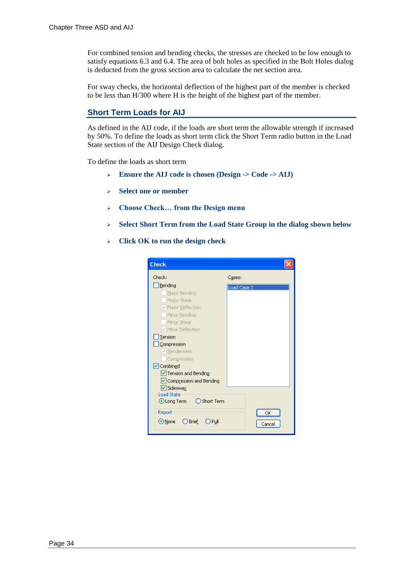
Chapter Three ASD and AIJ
Page 34
For combined tension and bending checks, the stresses are checked to be low enough to satisfy equations 6.3 and 6.4. The area of bolt holes as specified in the Bolt Holes dialog is deducted from the gross section area to calculate the net section area. For sway checks, the horizontal deflection of the highest part of the member is checked to be less than H/300 where H is the height of the highest part of the member.
Short Term Loads for AIJ
As defined in the AIJ code, if the loads are short term the allowable strength if increased by 50%. To define the loads as short term click the Short Term radio button in the Load State section of the AIJ Design Check dialog. To define the loads as short term
Ensure the AIJ code is chosen (Design -> Code -> AIJ)
Select one or member
Choose Check… from the Design menu
Select Short Term from the Load State Group in the dialog shown below
Click OK to run the design check
Chapter Four AS4100/NZS3404
Page 35
Chapter 4 AS4100 and NZS3404
This chapter describes the implementation of the Australian AS4100 and New Zealand NZS3404 steel design codes within Multiframe Steel Codes. It provides a step-by-step description of how to modify the design properties used by each code.
Notation
Design Checks
Bending
Tension
Compression
Combined Actions
Serviceability
Seismic (NZS3404)
Default Design Properties
Code Clauses Checked
Notation - AS4100 and NZS3404
The notation used in Multiframe Steel Codes generally follows that used in AS4100 and NZS3404. There are some minor differences that are noted below. In addition, some extra notation has been introduced to help clarify the different design quantities.
kte Correction factor for distribution of forces in a tension member (equivalent to kt in AS4100).
Ncx1 nominal member capacity in axial compression for buckling about the major principle axis computed using a maximum effective length factor (ke) of 1.0.
Ncy1 Nominal member capacity in axial compression for buckling about the minor principle axis computed using a maximum effective length factor (ke) of 1.0.
Design Checks - AS4100 and NZS3404
The types of checks are grouped into the categories; Bending, Tension, Compression, Combined, Serviceability and Seismic (NZS3404 only). The user may specify which of these checks are performed when a member is designed or checked using Multiframe Steel Codes.
Bending - AS4100 and NZS3404
The design of a member for bending consists of five design checks. These check the section capacity of the member about the major and minor axes, the shear capacity about both axes and the member, or buckling, capacity about the major axis. When performing a bending check it is necessary to specify how lateral buckling of the member is resisted. Restraint could be provided by other members, purlins, girts or by other structural elements that are not modelled in Multiframe such as concrete slabs. Multiframe Steel Codes provides three methods of specifying how a member is restrained against lateral buckling. The user may specify
Chapter Four AS4100/NZS3404
Page 36
That the member is fully restrained against lateral buckling in which case no lateral buckling checks will be performed. The location and type of lateral restraints applied to the member in which case Multiframe Steel Codes will appropriately divide the member into a number of spans and consider the capacity of each of these spans in determining the capacity of the member.
The laterally unbraced length (le) and moment modification factor (m). You may need to specify a number of properties relating to the location and type of lateral restraints and the stiffener spacing along the member
Lateral Restraints - AS4100 and NZS3404
To determine the moment member capacity of a member, it is necessary to know the spacing of any lateral restraints (if any) along the member. The restraints could be provided by purlins, girts or other structural elements, which are not modelled in Multiframe. Multiframe Steel Codes uses this information to determine the length of segments used in the design calculations. The lateral restraints acting at a particular section on a member are dependent upon which flange is the critical flange. For a member/segment restrained at both ends the critical flange is the flange under compression. For a cantilever or a segment with an unrestrained end, the critical flange is the tension flange. For each restraint on the member, the user must specify the type of restraint. As this depends upon which flange is the critical flange, the user must specify the type of lateral restraint that would be present at a section if i) The top flange were the critical flange, and ii) The bottom flange was the critical flange. Lateral restraints must always be specified at the ends of the beam and so the minimum number of lateral restraints is two. If no restraint exists at the end of a member then it should be specified as unrestrained. The initial lateral restraints applied to the member are full restraints at each end for either of the flanges being the critical flange. The different restraints acting on the member can be specified as;
Restraint Type Abbreviation
Fully restrained F
Partially restrained P
Laterally Restrained L
Unrestrained U
Continuous restraint C
Fully or partially restrained sections may also be specified as lateral rotational restraints using;
Restraint Type Abbreviation
Fully restrained and Rotationally restrained FR
Partial restrained and Rotationally restrained PR
The initial position of the loads is at the shear centre. If there are no transverse stiffeners, leave the stiffener spacing set to zero.
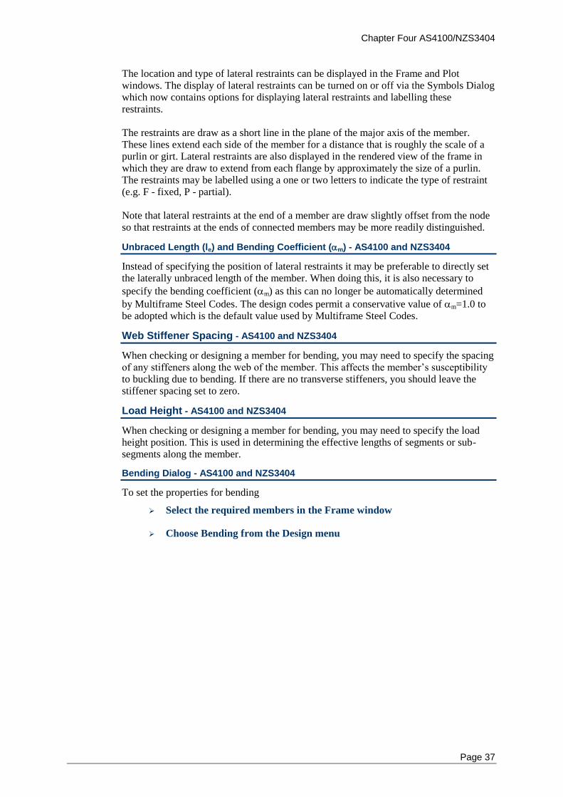
Chapter Four AS4100/NZS3404
Page 37
The location and type of lateral restraints can be displayed in the Frame and Plot windows. The display of lateral restraints can be turned on or off via the Symbols Dialog which now contains options for displaying lateral restraints and labelling these restraints. The restraints are draw as a short line in the plane of the major axis of the member. These lines extend each side of the member for a distance that is roughly the scale of a purlin or girt. Lateral restraints are also displayed in the rendered view of the frame in which they are draw to extend from each flange by approximately the size of a purlin. The restraints may be labelled using a one or two letters to indicate the type of restraint (e.g. F - fixed, P - partial). Note that lateral restraints at the end of a member are draw slightly offset from the node so that restraints at the ends of connected members may be more readily distinguished.
Unbraced Length (le) and Bending Coefficient (m) - AS4100 and NZS3404
Instead of specifying the position of lateral restraints it may be preferable to directly set the laterally unbraced length of the member. When doing this, it is also necessary to
specify the bending coefficient (m) as this can no longer be automatically determined
by Multiframe Steel Codes. The design codes permit a conservative value of m=1.0 to be adopted which is the default value used by Multiframe Steel Codes.
Web Stiffener Spacing - AS4100 and NZS3404
When checking or designing a member for bending, you may need to specify the spacing of any stiffeners along the web of the member. This affects the member’s susceptibility to buckling due to bending. If there are no transverse stiffeners, you should leave the stiffener spacing set to zero.
Load Height - AS4100 and NZS3404
When checking or designing a member for bending, you may need to specify the load height position. This is used in determining the effective lengths of segments or sub-segments along the member.
Bending Dialog - AS4100 and NZS3404
To set the properties for bending
Select the required members in the Frame window
Choose Bending from the Design menu
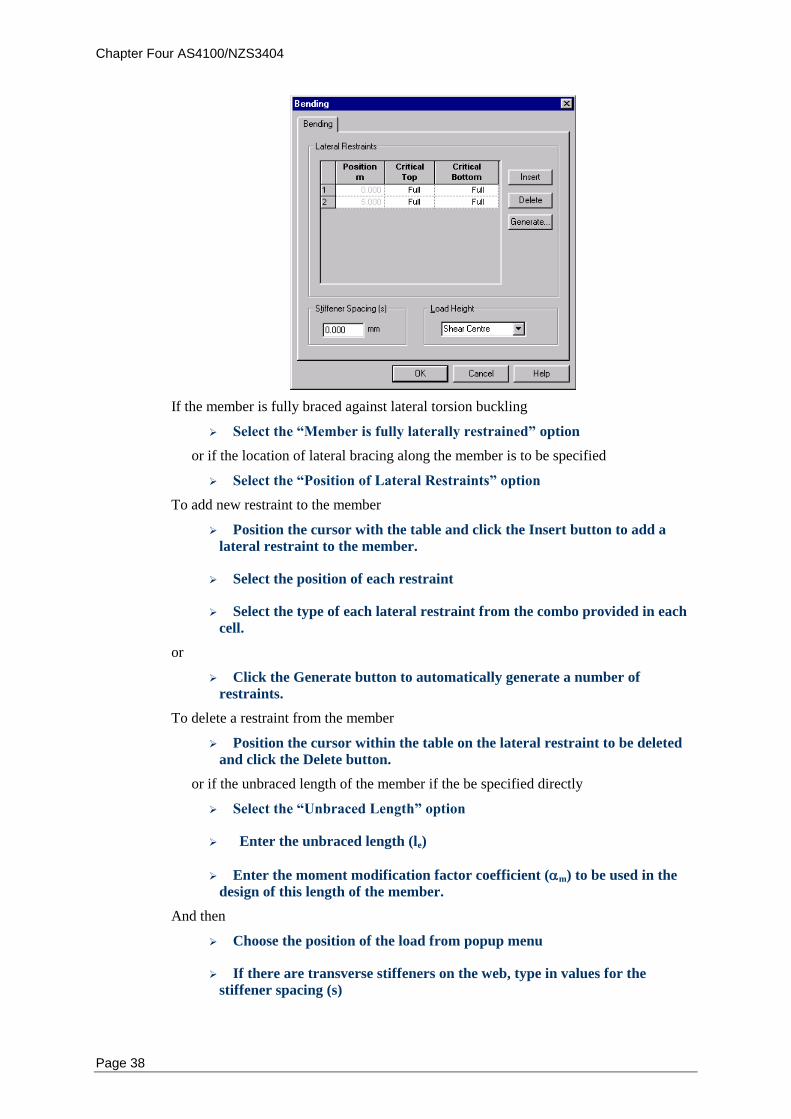
Chapter Four AS4100/NZS3404
Page 38
If the member is fully braced against lateral torsion buckling
Select the “Member is fully laterally restrained” option
or if the location of lateral bracing along the member is to be specified
Select the “Position of Lateral Restraints” option
To add new restraint to the member
Position the cursor with the table and click the Insert button to add a
lateral restraint to the member.
Select the position of each restraint
Select the type of each lateral restraint from the combo provided in each
cell.
or
Click the Generate button to automatically generate a number of
restraints.
To delete a restraint from the member
Position the cursor within the table on the lateral restraint to be deleted
and click the Delete button.
or if the unbraced length of the member if the be specified directly
Select the “Unbraced Length” option
Enter the unbraced length (le)
Enter the moment modification factor coefficient (m) to be used in the
design of this length of the member.
And then
Choose the position of the load from popup menu
If there are transverse stiffeners on the web, type in values for the
stiffener spacing (s)
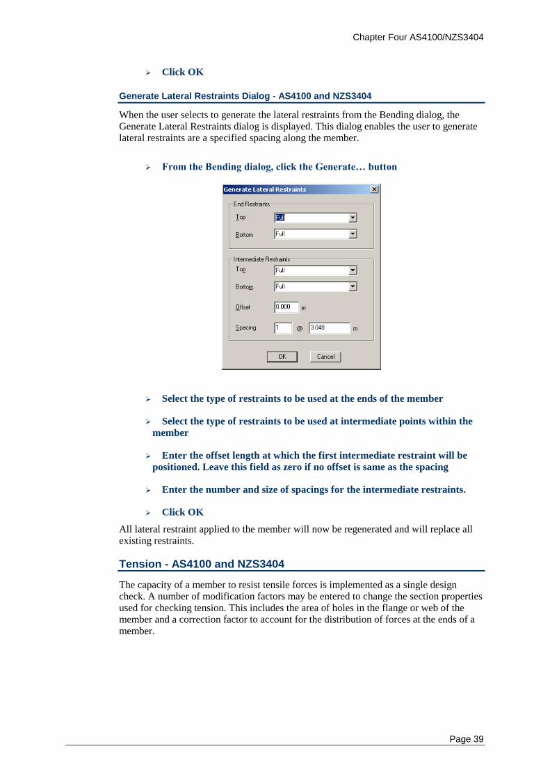
Chapter Four AS4100/NZS3404
Page 39
Click OK
Generate Lateral Restraints Dialog - AS4100 and NZS3404
When the user selects to generate the lateral restraints from the Bending dialog, the Generate Lateral Restraints dialog is displayed. This dialog enables the user to generate lateral restraints are a specified spacing along the member.
From the Bending dialog, click the Generate… button
Select the type of restraints to be used at the ends of the member
Select the type of restraints to be used at intermediate points within the
member
Enter the offset length at which the first intermediate restraint will be
positioned. Leave this field as zero if no offset is same as the spacing
Enter the number and size of spacings for the intermediate restraints.
Click OK
All lateral restraint applied to the member will now be regenerated and will replace all existing restraints.
Tension - AS4100 and NZS3404
The capacity of a member to resist tensile forces is implemented as a single design check. A number of modification factors may be entered to change the section properties used for checking tension. This includes the area of holes in the flange or web of the member and a correction factor to account for the distribution of forces at the ends of a member.
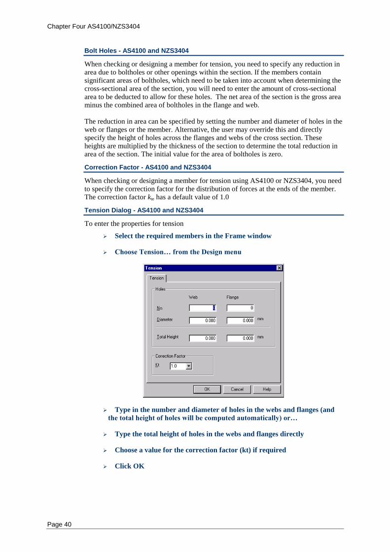
Chapter Four AS4100/NZS3404
Page 40
Bolt Holes - AS4100 and NZS3404
When checking or designing a member for tension, you need to specify any reduction in area due to boltholes or other openings within the section. If the members contain significant areas of boltholes, which need to be taken into account when determining the cross-sectional area of the section, you will need to enter the amount of cross-sectional area to be deducted to allow for these holes. The net area of the section is the gross area minus the combined area of boltholes in the flange and web. The reduction in area can be specified by setting the number and diameter of holes in the web or flanges or the member. Alternative, the user may override this and directly specify the height of holes across the flanges and webs of the cross section. These heights are multiplied by the thickness of the section to determine the total reduction in area of the section. The initial value for the area of boltholes is zero.
Correction Factor - AS4100 and NZS3404
When checking or designing a member for tension using AS4100 or NZS3404, you need to specify the correction factor for the distribution of forces at the ends of the member. The correction factor kte has a default value of 1.0
Tension Dialog - AS4100 and NZS3404
To enter the properties for tension
Select the required members in the Frame window
Choose Tension… from the Design menu
Type in the number and diameter of holes in the webs and flanges (and
the total height of holes will be computed automatically) or…
Type the total height of holes in the webs and flanges directly
Choose a value for the correction factor (kt) if required
Click OK
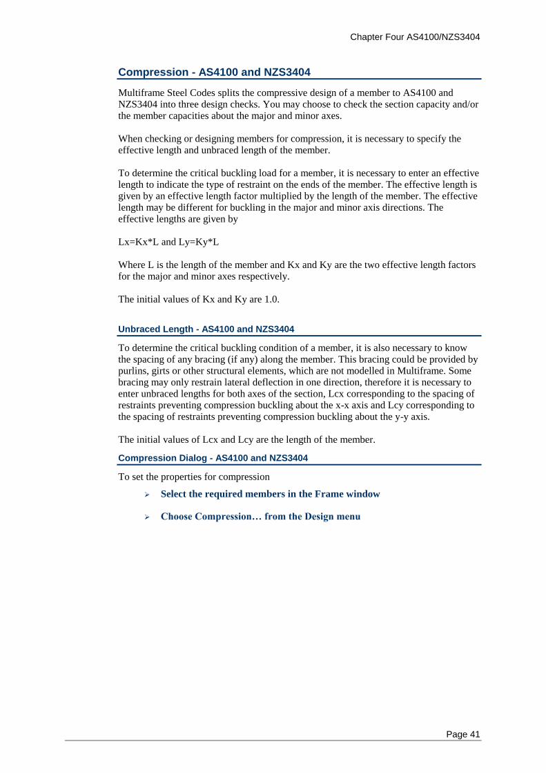
Chapter Four AS4100/NZS3404
Page 41
Compression - AS4100 and NZS3404
Multiframe Steel Codes splits the compressive design of a member to AS4100 and NZS3404 into three design checks. You may choose to check the section capacity and/or the member capacities about the major and minor axes. When checking or designing members for compression, it is necessary to specify the effective length and unbraced length of the member. To determine the critical buckling load for a member, it is necessary to enter an effective length to indicate the type of restraint on the ends of the member. The effective length is given by an effective length factor multiplied by the length of the member. The effective length may be different for buckling in the major and minor axis directions. The effective lengths are given by Lx=Kx*L and Ly=Ky*L Where L is the length of the member and Kx and Ky are the two effective length factors for the major and minor axes respectively. The initial values of Kx and Ky are 1.0.
Unbraced Length - AS4100 and NZS3404
To determine the critical buckling condition of a member, it is also necessary to know the spacing of any bracing (if any) along the member. This bracing could be provided by purlins, girts or other structural elements, which are not modelled in Multiframe. Some bracing may only restrain lateral deflection in one direction, therefore it is necessary to enter unbraced lengths for both axes of the section, Lcx corresponding to the spacing of restraints preventing compression buckling about the x-x axis and Lcy corresponding to the spacing of restraints preventing compression buckling about the y-y axis. The initial values of Lcx and Lcy are the length of the member.
Compression Dialog - AS4100 and NZS3404
To set the properties for compression
Select the required members in the Frame window
Choose Compression… from the Design menu
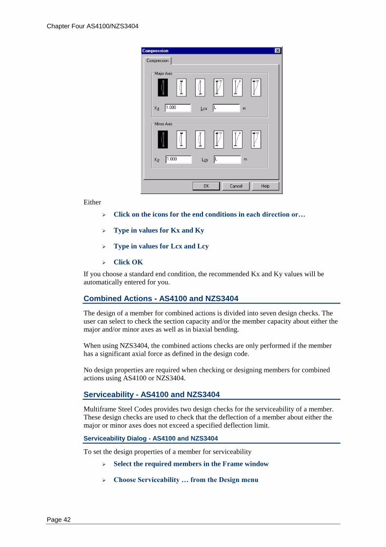
Chapter Four AS4100/NZS3404
Page 42
Either
Click on the icons for the end conditions in each direction or…
Type in values for Kx and Ky
Type in values for Lcx and Lcy
Click OK
If you choose a standard end condition, the recommended Kx and Ky values will be automatically entered for you.
Combined Actions - AS4100 and NZS3404
The design of a member for combined actions is divided into seven design checks. The user can select to check the section capacity and/or the member capacity about either the major and/or minor axes as well as in biaxial bending. When using NZS3404, the combined actions checks are only performed if the member has a significant axial force as defined in the design code. No design properties are required when checking or designing members for combined actions using AS4100 or NZS3404.
Serviceability - AS4100 and NZS3404
Multiframe Steel Codes provides two design checks for the serviceability of a member. These design checks are used to check that the deflection of a member about either the major or minor axes does not exceed a specified deflection limit.
Serviceability Dialog - AS4100 and NZS3404
To set the design properties of a member for serviceability
Select the required members in the Frame window
Choose Serviceability … from the Design menu
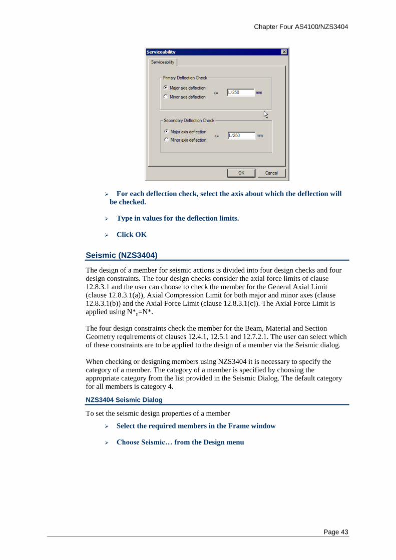
Chapter Four AS4100/NZS3404
Page 43
For each deflection check, select the axis about which the deflection will
be checked.
Type in values for the deflection limits.
Click OK
Seismic (NZS3404)
The design of a member for seismic actions is divided into four design checks and four design constraints. The four design checks consider the axial force limits of clause 12.8.3.1 and the user can choose to check the member for the General Axial Limit (clause 12.8.3.1(a)), Axial Compression Limit for both major and minor axes (clause 12.8.3.1(b)) and the Axial Force Limit (clause 12.8.3.1(c)). The Axial Force Limit is applied using N*g=N*. The four design constraints check the member for the Beam, Material and Section Geometry requirements of clauses 12.4.1, 12.5.1 and 12.7.2.1. The user can select which of these constraints are to be applied to the design of a member via the Seismic dialog. When checking or designing members using NZS3404 it is necessary to specify the category of a member. The category of a member is specified by choosing the appropriate category from the list provided in the Seismic Dialog. The default category for all members is category 4.
NZS3404 Seismic Dialog
To set the seismic design properties of a member
Select the required members in the Frame window
Choose Seismic… from the Design menu
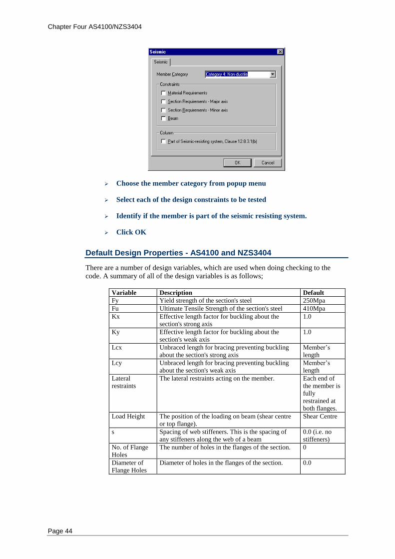
Chapter Four AS4100/NZS3404
Page 44
Choose the member category from popup menu
Select each of the design constraints to be tested
Identify if the member is part of the seismic resisting system.
Click OK
Default Design Properties - AS4100 and NZS3404
There are a number of design variables, which are used when doing checking to the code. A summary of all of the design variables is as follows;
Variable Description Default
Fy Yield strength of the section's steel 250Mpa
Fu Ultimate Tensile Strength of the section's steel 410Mpa
Kx Effective length factor for buckling about the section's strong axis
1.0
Ky Effective length factor for buckling about the section's weak axis
1.0
Lcx Unbraced length for bracing preventing buckling about the section's strong axis
Member’s length
Lcy Unbraced length for bracing preventing buckling about the section's weak axis
Member’s length
Lateral restraints
The lateral restraints acting on the member. Each end of the member is fully restrained at both flanges.
Load Height The position of the loading on beam (shear centre or top flange).
Shear Centre
s Spacing of web stiffeners. This is the spacing of any stiffeners along the web of a beam
0.0 (i.e. no stiffeners)
No. of Flange Holes
The number of holes in the flanges of the section. 0
Diameter of Flange Holes
Diameter of holes in the flanges of the section. 0.0
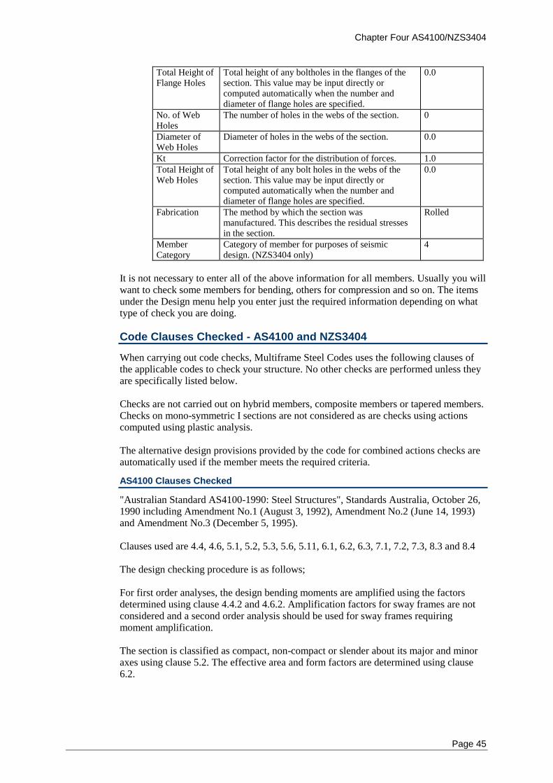
Chapter Four AS4100/NZS3404
Page 45
Total Height of Flange Holes
Total height of any boltholes in the flanges of the section. This value may be input directly or computed automatically when the number and diameter of flange holes are specified.
0.0
No. of Web Holes
The number of holes in the webs of the section. 0
Diameter of Web Holes
Diameter of holes in the webs of the section. 0.0
Kt Correction factor for the distribution of forces. 1.0
Total Height of Web Holes
Total height of any bolt holes in the webs of the section. This value may be input directly or computed automatically when the number and diameter of flange holes are specified.
0.0
Fabrication The method by which the section was manufactured. This describes the residual stresses in the section.
Rolled
Member Category
Category of member for purposes of seismic design. (NZS3404 only)
4
It is not necessary to enter all of the above information for all members. Usually you will want to check some members for bending, others for compression and so on. The items under the Design menu help you enter just the required information depending on what type of check you are doing.
Code Clauses Checked - AS4100 and NZS3404
When carrying out code checks, Multiframe Steel Codes uses the following clauses of the applicable codes to check your structure. No other checks are performed unless they are specifically listed below. Checks are not carried out on hybrid members, composite members or tapered members. Checks on mono-symmetric I sections are not considered as are checks using actions computed using plastic analysis. The alternative design provisions provided by the code for combined actions checks are automatically used if the member meets the required criteria.
AS4100 Clauses Checked
"Australian Standard AS4100-1990: Steel Structures", Standards Australia, October 26, 1990 including Amendment No.1 (August 3, 1992), Amendment No.2 (June 14, 1993) and Amendment No.3 (December 5, 1995). Clauses used are 4.4, 4.6, 5.1, 5.2, 5.3, 5.6, 5.11, 6.1, 6.2, 6.3, 7.1, 7.2, 7.3, 8.3 and 8.4 The design checking procedure is as follows; For first order analyses, the design bending moments are amplified using the factors determined using clause 4.4.2 and 4.6.2. Amplification factors for sway frames are not considered and a second order analysis should be used for sway frames requiring moment amplification. The section is classified as compact, non-compact or slender about its major and minor axes using clause 5.2. The effective area and form factors are determined using clause 6.2.
Chapter Four AS4100/NZS3404
Page 46
For major and minor bending section checks, the design bending moment is checked to be less than the nominal section moment design capacity as found using clause 5.2. For bending member checks, the design bending moment about the major principle axis is checked to be less than the nominal member moment design capacity as found using
clauses 5.3 and 5.6. Clause 5.6.3 and clause 5.6.4 are NOT considered. For major and minor shear checks, the design shear force is checked to be less than the
nominal shear capacity found from section 5.11. The flange restraint factor (f) of
clause 5.11.5.2 is always set to 1.0. For tension checks, the design axial tension force is checked to be less than the nominal section design capacity in tension as computed using clause 7.2. For compression section checks, the design axial compressive force is checked to be less than the nominal section design capacity in compression as computed using clause 6.2. For major and minor compression member checks, the design axial compressive force is checked to be less than the nominal member design capacity in compression as
computed using clause 6.3. Clause 6.3.4 is NOT considered. For all combined action section checks, the design axial force (N*) is the maximum axial force in the member, and the design bending moments (Mx*, and My*) are the
maximum bending moments in the member. For major and minor combined section checks, the design bending moment is checked to be less than the nominal section moment design capacity reduced by axial force (compression or tension) as computed using clause 8.3.2 and 8.3.3. For combined biaxial section checks, the design bending moments are checked to satisfy clause 8.3.4. For major and minor combined in-plane member checks, the design bending moment is checked to be less than the nominal in-plane member moment design capacity as
computed using clause 8.4.2. Clause 8.4.3 is NOT considered. For combined out-of-plane member checks, the design bending moment about the major axis is checked to be less than the nominal in-plane member moment design capacity as computed using clause 8.4.4. For combined biaxial member checks, the design bending moments are checked to satisfy clause 8.4.5.
Clause 8.4.6 is NOT considered.
NZS3404 Clauses Checked
"New Zealand Standard NZS3404-1997: Steel Structures", Standards New Zealand, 26th
June 1997, including Draft Amendment No.1 (August, 2000). Clauses used are 4.4, 4.8, 5.1, 5.2, 5.3, 5.6, 5.11, 6.1, 6.2, 6.3, 7.1, 7.2, 7.3, 8.1, 8.3, 8.3, 12.4, 12.5,12.7 and 12.8. The design checking procedure is as follows;
Chapter Four AS4100/NZS3404
Page 47
For first order analyses, the design bending moments are amplified using the factors determined using clause 4.4.2 and 4.8.2. Amplification factors for sway frames are not considered and a second order analysis should be used for sway frames requiring moment amplification. The section is classified as compact, non-compact or slender about its major and minor axes using clause 5.2. The effective area and form factors are determined using clause 6.2. The member is checked for compliance to clauses 12.4.1.1, 12.5.1.1 and 12.7.2.1. Compliance of clause 12.4.1.1 only considers the maximum yield stress and the maximum ratio of (fy/fu). For major and minor bending section checks, the design bending moment is checked to be less than the nominal section moment design capacity as found using clause 5.2. For bending member checks, the design bending moment about the major principle axis is checked to be less than the nominal member moment design capacity as found using
clauses 5.3 and 5.6. Clause 5.6.3 and clause 5.6.4 are NOT considered. For major and minor shear checks, the design shear force is checked to be less than the
nominal shear capacity found from section 5.11. The flange restraint factor (f) of
clause 5.11.5.2 is always set to 1.0. For tension checks, the design axial tension force is checked to be less than the nominal section design capacity in tension as computed using clause 7.2. For compression section checks, the design axial compressive force is checked to be less than the nominal section design capacity in compression as computed using clause 6.2. For major and minor compression member checks, the design axial compressive force is checked to be less than the nominal member design capacity in compression as
computed using clause 6.3. Clause 6.3.4 is NOT considered. For all combined action section checks, the design axial force (N*) is the maximum axial force in the member, and the design bending moments (Mx*, and My*) are the
maximum bending moments in the member. If any combined action checks are to be considered, the member is first checked to determine if it has a significant axial force in accordance with clause 8.1.4. For members without a significant axial force all combined action checks are skipped. The member is checked to see if the use of alternative design criteria is acceptable. This check is conducted to clause 8.1.5 but does not consider the plate slenderness limits of clause 8.1.5 (b)(i). Hence, alternative design provisions will only be used if the cross section is compact. For major and minor combined section checks, the design bending moment is checked to be less than the nominal section moment design capacity reduced by axial force (compression or tension) as computed using clause 8.3.2 and 8.3.3. For combined biaxial section checks, the design bending moments are checked to satisfy clause 8.3.4.
Chapter Four AS4100/NZS3404
Page 48
For major and minor combined in-plane member checks, the design bending moment is checked to be less than the nominal in-plane member moment design capacity as
computed using clause 8.4.2. Clause 8.4.3 is NOT considered. For combined out-of-plane member checks, the design bending moment about the major axis is checked to be less than the nominal in-plane member moment design capacity as computed using clause 8.4.4. For combined biaxial member checks, the design bending moments are checked to satisfy clause 8.4.5.
Clause 8.4.6 is NOT considered. For seismic member checks, the design axial force is checked to satisfy clauses 12.8.3.1(a), (b) and (c). Note that clause 12.8.3.1(c) is checked using N*g=N*.
Chapter Five LRFD code
Page 49
Chapter 5 LRFD
This chapter describes the implementation of the AISC “Load and Resistance Factor Design Specification for Structural Steel Buildings “ (LRFD) and “Load and Resistance Factor Design Specification for Single Angle Members” (LRFD SAM) steel design codes within Multiframe Steel Codes. It provides a step-by-step description of how to modify the design properties used by the code.
Notation
Design Checks
Bending
Tension
Tension Dialog
Compression
Combined Actions
Serviceability
Default Design Properties
Code Clauses Checked
Notation - LFRD
The notation used in Multiframe Steel Codes generally follows that used in the LRFD and LRFD SAM. Use has been made of subscripts to clarify the axis of the member to which a quantity refers. For example, the nominal flexural strengths about the X and Y axes are denoted Mnx and Mny respectively. The geometric axes of a member are denoted as the X and Y axes where X represented the horizontal axis of the member and Y the vertical axis of the member. For design to LRFD, it is assumed that the X axis is the major axis and Y is the minor axis. For most sections these corresponds to the principal axes but for some sections, such as angles, the geometric axes do not correspond to the principal axes. In this case, quantities pertaining to the major and minor principle axes are denoted using U and V respectively.
Design Checks - LFRD
The types of checks are grouped into the categories; Bending, Tension, Compression, Combined and Serviceability. The user may specify which of these checks are performed when a member is designed or checked using Multiframe Steel Codes.
Bending - LFRD
The design of a member for bending is divided into four design checks. These check the flexural and shear capacity of the member about the major and minor axes. Each of these checks may consider one or more limit states depending upon the section and the actions within the member. When performing a bending check it is necessary to specify how lateral buckling of the member is resisted. Restraint could be provided by other members, purlins, girts or by other structural elements that are not modelled in Multiframe such as concrete slabs. Multiframe Steel Codes provides three methods of specifying how a member is restrained against lateral buckling. The user may specify
Chapter Five LRFD
Page 50
That the member is fully restrained against lateral buckling in which case no lateral buckling checks will be performed. The location and type of lateral restraints applied to the member in which case Multiframe Steel Codes will appropriately divide the member into a number of spans and consider the capacity of each of these spans in determining the capacity of the member. The laterally unbraced length (Lb) and bending coefficient (Cb). You may need to specify a number of properties relating to the location and type of lateral restraints and the stiffener spacing along the member
Lateral Restraints - LFRD
If the spacing of lateral restraints along the member is specified, Multiframe Steel Codes uses this information to break the member up into a number of spans in order to determine lateral torsion buckling capacity of each span. In Multiframe Steel Codes, these spans are known as segments.
Each lateral restraint specified by the user is assumed to provide bracing against lateral displacement of the critical flange and/or prevent twist of the cross section. At any cross section, the critical flange is the flange that, in the absence of any restraint at that cross section, would deflect the furthest during buckling of the member. In most members the critical flange will be the compression flange. However for a cantilevered member, the critical flange is the tension flange. For each restraint located along a member, the user must specify the type of restraint. As this depends upon which flange is the critical flange, which is not know a priori, the user must specify the type of lateral restraint that would be present at a section if
The top flange was the critical flange, and
The bottom flange was the critical flange.
In LRFD no distinction is made between different types of lateral restraints. However, to be compatible with other design codes, Multiframe Steel Codes allows for lateral restraints at a cross section to be classified as follows
Full Restraint –supports the cross section against lateral displacement of the
critical flange and prevents twist of the cross section.
Partial Restraint – provides support against lateral displacement of the section at a
point other than the critical flange and prevents twist of the cross section.
Lateral Restraint – resists lateral displacement of the critical flange only.
For the purpose of design in LRFD, each of these restraint types is consider adequate to provide lateral support to the cross section at which they are applied. Lateral restraints must always be specified at the ends of the beam and so the minimum number of lateral restraints is two. If no restraint exists at the end of a member then it should be specified as unrestrained in which case the member would be regarded as a cantilever. The initial lateral restraints applied to the member are full restraints at each end for either of the flanges being the critical flange.
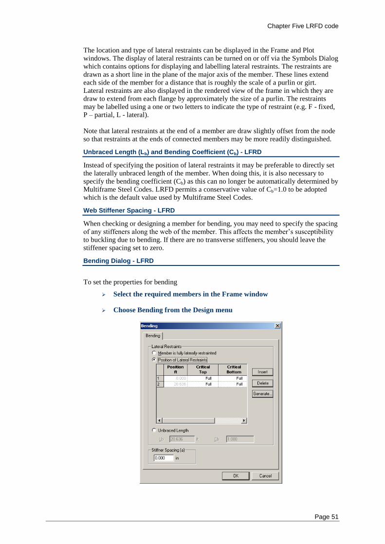
Chapter Five LRFD code
Page 51
The location and type of lateral restraints can be displayed in the Frame and Plot windows. The display of lateral restraints can be turned on or off via the Symbols Dialog which contains options for displaying and labelling lateral restraints. The restraints are drawn as a short line in the plane of the major axis of the member. These lines extend each side of the member for a distance that is roughly the scale of a purlin or girt. Lateral restraints are also displayed in the rendered view of the frame in which they are draw to extend from each flange by approximately the size of a purlin. The restraints may be labelled using a one or two letters to indicate the type of restraint (e.g. F - fixed, P – partial, L - lateral). Note that lateral restraints at the end of a member are draw slightly offset from the node so that restraints at the ends of connected members may be more readily distinguished.
Unbraced Length (Lb) and Bending Coefficient (Cb) - LFRD
Instead of specifying the position of lateral restraints it may be preferable to directly set the laterally unbraced length of the member. When doing this, it is also necessary to specify the bending coefficient (Cb) as this can no longer be automatically determined by Multiframe Steel Codes. LRFD permits a conservative value of Cb=1.0 to be adopted which is the default value used by Multiframe Steel Codes.
Web Stiffener Spacing - LFRD
When checking or designing a member for bending, you may need to specify the spacing of any stiffeners along the web of the member. This affects the member’s susceptibility to buckling due to bending. If there are no transverse stiffeners, you should leave the stiffener spacing set to zero.
Bending Dialog - LFRD
To set the properties for bending
Select the required members in the Frame window
Choose Bending from the Design menu
Chapter Five LRFD
Page 52
Select the “Member is fully laterally restrained” option, or
Select the “Position of Lateral Restraints” option, and then
To add new restraint to the member
Position the cursor with the table and click the Insert button to add a
lateral restraint to the member.
Select the position of each restraint
Select the type of each lateral restraint from the combo provided in each
cell.
or
Click the Generate button to automatically generate a number of
restraints.
To delete a restraint from the member
Position the cursor within the table on the lateral restraint to be deleted
and click the Delete button.
Or select the “Unbraced Length” option, and then
Enter the unbraced length (le)
Enter the moment modification factor coefficient (m) to be used in the
design of this length of the member.
Choose the position of the load from popup menu
If there are transverse stiffeners on the web, type in values for the
stiffener spacing (s)
Click OK
Generate Lateral Restraints Dialog - LFRD
When the user selects to generate the lateral restraints from the Bending dialog, the Generate Lateral Restraints dialog is displayed. This dialog enables the user to generate lateral restraints are a specified spacing along the member.
From the Bending dialog, click the Generate… button
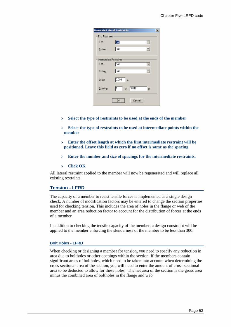
Chapter Five LRFD code
Page 53
Select the type of restraints to be used at the ends of the member
Select the type of restraints to be used at intermediate points within the
member
Enter the offset length at which the first intermediate restraint will be
positioned. Leave this field as zero if no offset is same as the spacing
Enter the number and size of spacings for the intermediate restraints.
Click OK
All lateral restraint applied to the member will now be regenerated and will replace all existing restraints.
Tension - LFRD
The capacity of a member to resist tensile forces is implemented as a single design check. A number of modification factors may be entered to change the section properties used for checking tension. This includes the area of holes in the flange or web of the member and an area reduction factor to account for the distribution of forces at the ends of a member. In addition to checking the tensile capacity of the member, a design constraint will be applied to the member enforcing the slenderness of the member to be less than 300.
Bolt Holes - LFRD
When checking or designing a member for tension, you need to specify any reduction in area due to boltholes or other openings within the section. If the members contain significant areas of boltholes, which need to be taken into account when determining the cross-sectional area of the section, you will need to enter the amount of cross-sectional area to be deducted to allow for these holes. The net area of the section is the gross area minus the combined area of boltholes in the flange and web.
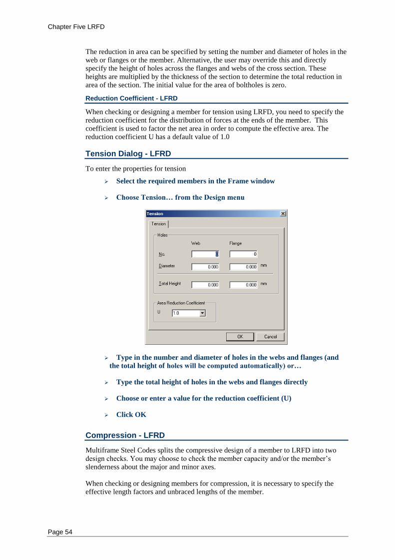
Chapter Five LRFD
Page 54
The reduction in area can be specified by setting the number and diameter of holes in the web or flanges or the member. Alternative, the user may override this and directly specify the height of holes across the flanges and webs of the cross section. These heights are multiplied by the thickness of the section to determine the total reduction in area of the section. The initial value for the area of boltholes is zero.
Reduction Coefficient - LFRD
When checking or designing a member for tension using LRFD, you need to specify the reduction coefficient for the distribution of forces at the ends of the member. This coefficient is used to factor the net area in order to compute the effective area. The reduction coefficient U has a default value of 1.0
Tension Dialog - LFRD
To enter the properties for tension
Select the required members in the Frame window
Choose Tension… from the Design menu
Type in the number and diameter of holes in the webs and flanges (and
the total height of holes will be computed automatically) or…
Type the total height of holes in the webs and flanges directly
Choose or enter a value for the reduction coefficient (U)
Click OK
Compression - LFRD
Multiframe Steel Codes splits the compressive design of a member to LRFD into two design checks. You may choose to check the member capacity and/or the member’s slenderness about the major and minor axes. When checking or designing members for compression, it is necessary to specify the effective length factors and unbraced lengths of the member.
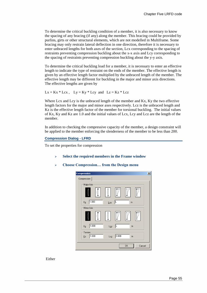
Chapter Five LRFD code
Page 55
To determine the critical buckling condition of a member, it is also necessary to know the spacing of any bracing (if any) along the member. This bracing could be provided by purlins, girts or other structural elements, which are not modelled in Multiframe. Some bracing may only restrain lateral deflection in one direction, therefore it is necessary to enter unbraced lengths for both axes of the section, Lcx corresponding to the spacing of restraints preventing compression buckling about the x-x axis and Lcy corresponding to the spacing of restraints preventing compression buckling about the y-y axis. To determine the critical buckling load for a member, it is necessary to enter an effective length to indicate the type of restraint on the ends of the member. The effective length is given by an effective length factor multiplied by the unbraced length of the member. The effective length may be different for buckling in the major and minor axis directions. The effective lengths are given by Lx = Kx * Lcx , Ly = Ky * Lcy and Lz = Kz * Lcz Where Lcx and Lcy is the unbraced length of the member and Kx, Ky the two effective length factors for the major and minor axes respectively. Lcz is the unbraced length and Kz is the effective length factor of the member for torsional buckling. The initial values of Kx, Ky and Kz are 1.0 and the initial values of Lcx, Lcy and Lcz are the length of the member. In addition to checking the compressive capacity of the member, a design constraint will be applied to the member enforcing the slenderness of the member to be less than 200.
Compression Dialog - LFRD
To set the properties for compression
Select the required members in the Frame window
Choose Compression… from the Design menu
Either
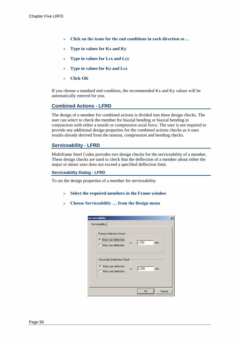
Chapter Five LRFD
Page 56
Click on the icons for the end conditions in each direction or…
Type in values for Kx and Ky
Type in values for Lcx and Lcy
Type in values for Kz and Lcz
Click OK
If you choose a standard end condition, the recommended Kx and Ky values will be automatically entered for you.
Combined Actions - LFRD
The design of a member for combined actions is divided into three design checks. The user can select to check the member for biaxial bending or biaxial bending in conjunction with either a tensile or compressive axial force. The user is not required to provide any additional design properties for the combined actions checks as it uses results already derived from the tension, compression and bending checks.
Serviceability - LFRD
Multiframe Steel Codes provides two design checks for the serviceability of a member. These design checks are used to check that the deflection of a member about either the major or minor axes does not exceed a specified deflection limit.
Serviceability Dialog - LFRD
To set the design properties of a member for serviceability
Select the required members in the Frame window
Choose Serviceability … from the Design menu
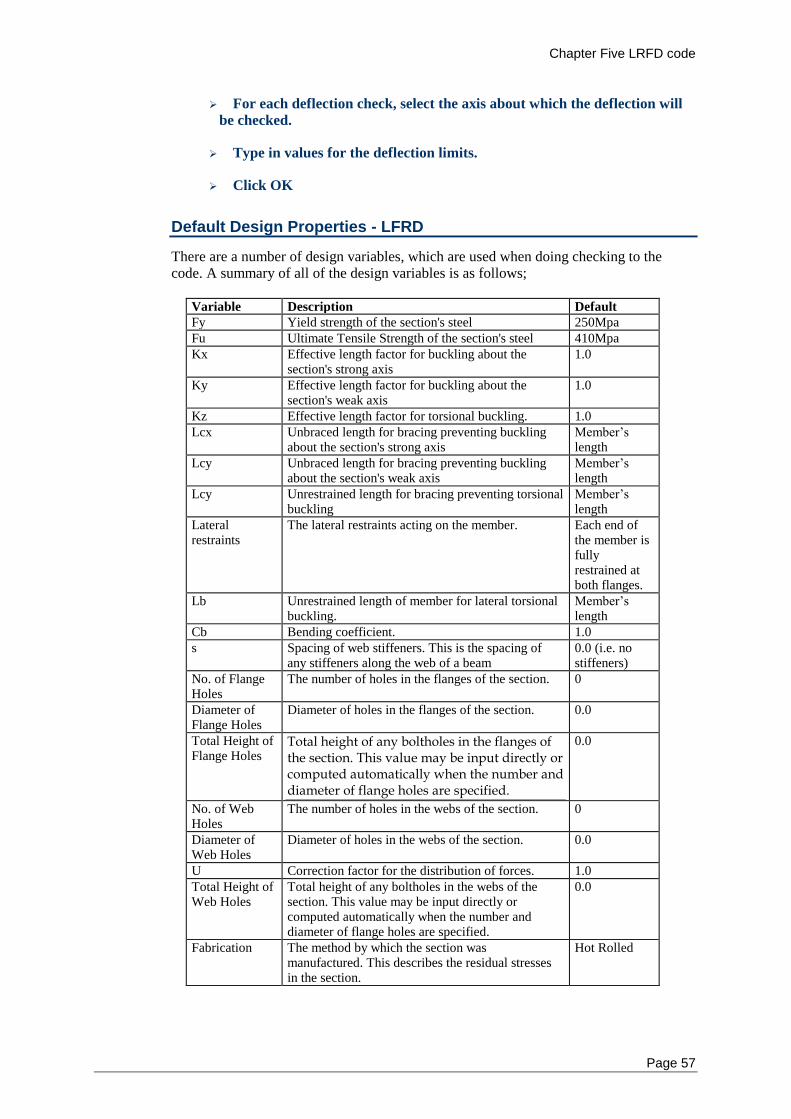
Chapter Five LRFD code
Page 57
For each deflection check, select the axis about which the deflection will
be checked.
Type in values for the deflection limits.
Click OK
Default Design Properties - LFRD
There are a number of design variables, which are used when doing checking to the code. A summary of all of the design variables is as follows;
Variable Description Default
Fy Yield strength of the section's steel 250Mpa
Fu Ultimate Tensile Strength of the section's steel 410Mpa
Kx Effective length factor for buckling about the section's strong axis
1.0
Ky Effective length factor for buckling about the section's weak axis
1.0
Kz Effective length factor for torsional buckling. 1.0
Lcx Unbraced length for bracing preventing buckling about the section's strong axis
Member’s length
Lcy Unbraced length for bracing preventing buckling about the section's weak axis
Member’s length
Lcy Unrestrained length for bracing preventing torsional buckling
Member’s length
Lateral restraints
The lateral restraints acting on the member. Each end of the member is fully restrained at both flanges.
Lb Unrestrained length of member for lateral torsional buckling.
Member’s length
Cb Bending coefficient. 1.0
s Spacing of web stiffeners. This is the spacing of any stiffeners along the web of a beam
0.0 (i.e. no stiffeners)
No. of Flange Holes
The number of holes in the flanges of the section. 0
Diameter of Flange Holes
Diameter of holes in the flanges of the section. 0.0
Total Height of Flange Holes
Total height of any boltholes in the flanges of the section. This value may be input directly or computed automatically when the number and diameter of flange holes are specified.
0.0
No. of Web Holes
The number of holes in the webs of the section. 0
Diameter of Web Holes
Diameter of holes in the webs of the section. 0.0
U Correction factor for the distribution of forces. 1.0
Total Height of Web Holes
Total height of any boltholes in the webs of the section. This value may be input directly or computed automatically when the number and diameter of flange holes are specified.
0.0
Fabrication The method by which the section was manufactured. This describes the residual stresses in the section.
Hot Rolled
Chapter Five LRFD
Page 58
It is not necessary to enter all of the above information for all members. Usually you will want to check some members for bending, others for compression and so on. The items under the Design menu help you enter just the required information depending on what type of check you are doing.
Code Clauses Checked - LFRD
When carrying out code checks, Multiframe Steel Codes uses the following clauses of the applicable codes to check your structure. No other checks are performed unless they are specifically listed below. Checks are not carried out on composite members or tapered members. Checks on mono-symmetric I sections are not considered as are checks using actions computed using plastic analysis.
LRFD
LRFD SAM
LRFD Clauses Checked
"Load and Resistance Factor Design Specification for Structural Steel Buildings”, American Institute of Steel Construction, December 27, 1999. The design checking procedure is as follows: The net area of the section is computed by subtracting the area of holes in the section. The effective area is then calculated as the net area (An) times the area reduction coefficient (U). If the member is been checked for tension of compression, the slenderness of the section is checked to ensure that it meets the limits set out in Section B7. For angle members, the slenderness about either of the geometric axes is determined using the minimum radius of gyration of the section. If the member is a plate web girder, the section is checked to determine is if meets the web slenderness limits specified in Appendix G1. For each serviceability load case: The maximum local displacement of the member is compared to the deflection limits specified deflection limits. For each load case representing a strength limit state, The design actions, or required strengths, of the member are determined as the maximum moment, shears and axial forces within the member. For first order analyses, the design bending moments are amplified using the factors determined using clause C2. Only moment amplification of braced frames is considered which corresponds to the situation in which no moments result from the lateral translation of the frame. As such, moment amplification is computed using only the first term of the right hand side of equation C1-1. Amplification factors for sway frames are not considered and a second order analysis should be used for sway frames requiring moment amplification.
Chapter Five LRFD code
Page 59
The plate elements of the section will be classified as Compact/Non-Compact/Slender as per the requirements of clause B5.1 and Table B5-1. These elements may also be classified as Very Slender if they exceed the limitations set out in Table A-F1.1. If the moments in the member are less than one ten thousandth of the yield moments the section is considered to be in pure compression and will be classified accordingly. If an element of the section is found to be slender, the stiffness reduction factors Q, Qa and Qs will be determined as set out in Appendix B. For tension checks, the capacity of the member is determined in accordance with section D1. For compression checks, the capacity of the member is firstly computed for the limit states of flexural buckling about the major and minor axis is accordance with clause E2. The capacity of the member for the limit state of flexural torsional-buckling is then computed using clauses E3 and Appendix E. The compressive capacity of the member is regarded as being the minimum capacity determined for these three limit states. For bending checks the provisions of Appendix F1 are used. For each of the failure modes, yielding, flange local buckling, web local buckling and lateral torsional buckling,
, p and r values are calculated. The values are based upon the section shape and the
axis of bending and are derived from Table A-F1.1. After the various values have been calculated they are then compared to find the appropriate equation to calculate Mn, Equ. A-F1-1 to 4. Each Mn value for the failure modes are then compared with the lowest value governing. Flange local bucking will only be considered for sections with non-compact flanges. Similarly, web local buckling will only be considered for sections with non-compact webs. The design for shear is carried out in accordance with clause F2 using the provisions of Appendix F2.2 when a stiffener spacing is specified. For plate girders with slender web
elements, the provisions of Appendix G3 will be utilised instead. No calculations are
conducted using Chapters K or J. For the biaxial bending check, interaction equations of Appendix H1 are evaluated
ignoring the axial force term. The expressions are computed using the maximum actions in the members. If this check fails, the user For the combined action check for flexure and compression, the member is checked in accordance with clause H1.1 using the design moments about the major and minor axes. A more refined
LRFD SAM Clauses Checked
"Load and Resistance Factor Design Specification for Single Angle Members”, American Institute of Steel Construction, November 10, 2000. The design checking procedure is the same as described above for LRFD except that: The section is classified using the limits set out in clause 4 of LRFD SAM. The same clause is used to compute the slenderness reduction factors and effective area of the section. Clause 2 of LRFD SAM is used to determine the tensile capacity of the member.
Chapter Five LRFD
Page 60
For the bending checks, the shear is determined using clause 3 of LRFD SAM while the flexural capacity is determined using clause 5 of LRFD SAM.
The lateral-torsional buckling capacity of the member for the limit state of lateral-
torsion buckling of unequal angle sections without lateral torsion restraint or
sections modelled about their principle is not yet supported. When such a section is
encountered, the member will have determined to have no flexural capacity. The capacity of a member under combined forces is computed using clause 6 of LRFD SAM in place of the provisions in clause H or LRFD.
Chapter Six BS5950
Page 61
Chapter 6 BS5950
This chapter describes the implementation of the British BS5950 steel design code within Multiframe Steel Codes. It provides a step-by-step description of how to modify the design properties used by the code.
Notation
Design Checks
Bending
Tension
Compression
Combined Actions
Serviceability
Default Design Properties
Code Clauses Checked
Notation - BS5950
The notation used in Multiframe Steel Codes generally follows that used in BS5950.
Design Checks - BS5950
The types of checks are grouped into the categories; Bending, Tension, Compression, Combined and Serviceability. In addition, a number of auxiliary combined action checks have been included that consider axial force and bending about a single axis only. The user may specify which of these checks are performed when a member is designed or checked using Multiframe Steel Codes.
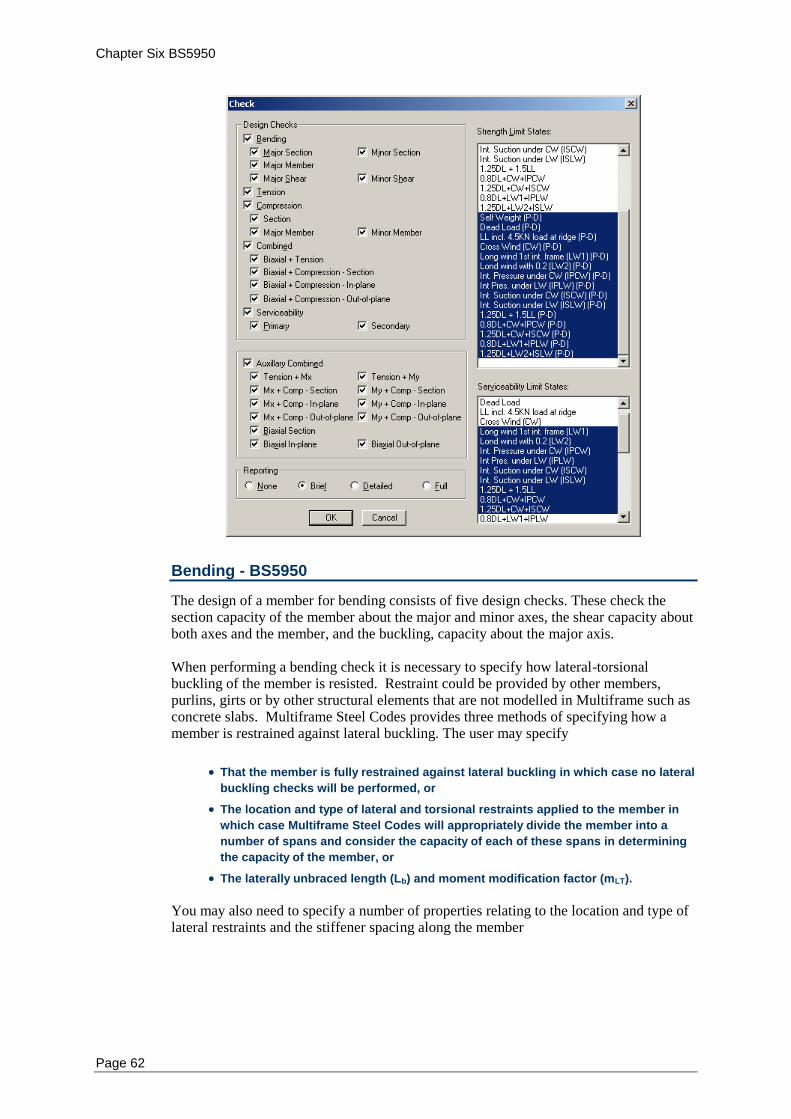
Chapter Six BS5950
Page 62
Bending - BS5950
The design of a member for bending consists of five design checks. These check the section capacity of the member about the major and minor axes, the shear capacity about both axes and the member, and the buckling, capacity about the major axis. When performing a bending check it is necessary to specify how lateral-torsional buckling of the member is resisted. Restraint could be provided by other members, purlins, girts or by other structural elements that are not modelled in Multiframe such as concrete slabs. Multiframe Steel Codes provides three methods of specifying how a member is restrained against lateral buckling. The user may specify
That the member is fully restrained against lateral buckling in which case no lateral
buckling checks will be performed, or
The location and type of lateral and torsional restraints applied to the member in
which case Multiframe Steel Codes will appropriately divide the member into a
number of spans and consider the capacity of each of these spans in determining
the capacity of the member, or
The laterally unbraced length (Lb) and moment modification factor (mLT).
You may also need to specify a number of properties relating to the location and type of lateral restraints and the stiffener spacing along the member
Chapter Six BS5950
Page 63
Lateral and Torsional Restraints - BS5950
To compute the buckling capacity of a member it is necessary to know the spacing of any lateral and torsional restraints (if any) along the member. The restraints could be provided by purlins, girts or other structural elements, which are not modelled in Multiframe. Multiframe Steel Codes uses this information to determine the length of segments used in the design calculations for lateral torsional buckling. In Multiframe Steel Codes, The restraint provided by a support is described by how it restraints the top and bottom flanges and how it restraints the cross-section of the member at that location against torsion. Restraints must always be specified at the ends of the member. If no actual restraint exists at the end of a member then it should be specified as unrestrained. Lateral restraints at the ends of a member may also be specified as providing either full or partial restraint against rotation on plan. By default, the ends of a member will be assumed to be laterally restraint at both the top and bottom flange but provide no resistance to on plan rotation of the member. Torsional restraints at the ends of a member may be specified as unrestrained, fully restrained, partially restrained or frictionally restrained. Partial restraints inhibit the rotation of the cross section by the connection of the bottom flange to the supports while frictional restraints resist rotation of the member about its longitudinal axis by only the pressure of the bottom flange onto its supports (Refer to Table 13 of BS5950). Intermediate restraints applied to the member may provide lateral and torsional restraint. No distinction is made for the on-plan rotational resistance that may be provided by lateral restraints. The location and type of lateral restraints can be displayed in the Frame and Plot windows. The display of lateral restraints can be turned on or off via the Symbols Dialog which now contains options for displaying lateral restraints and labelling these restraints. The restraints are draw as a short line in the plane of the major axis of the member. These lines extend each side of the member for a distance that is roughly the scale of a purlin or girt. Lateral restraints are also displayed in the rendered view of the frame in which they are draw to extend from each flange by approximately the size of a purlin. The restraints may be labelled using a one or two letters to indicate the type of restraint. Lateral are labelled using the following notation U – Unrestrained L – Lateral restraint LR – Lateral restraint with full restraint against rotation on plan LP – Lateral restraint with partial restraint against rotation on plan Note that lateral restraints at the end of a member are draw slightly offset from the node so that restraints at the ends of connected members may be more readily distinguished.
Unbraced Length (Lb) and Bending Coefficient (mLT) - BS5950
Instead of specifying the position of lateral restraints it may be preferable to directly set the laterally unbraced length of the member. When doing this, it is also necessary to specify the bending coefficient (mLT) as this can no longer be automatically determined by Multiframe Steel Codes. The design codes permit a conservative value of mLT =1.0 to be adopted which is the default value used by Multiframe Steel Codes.
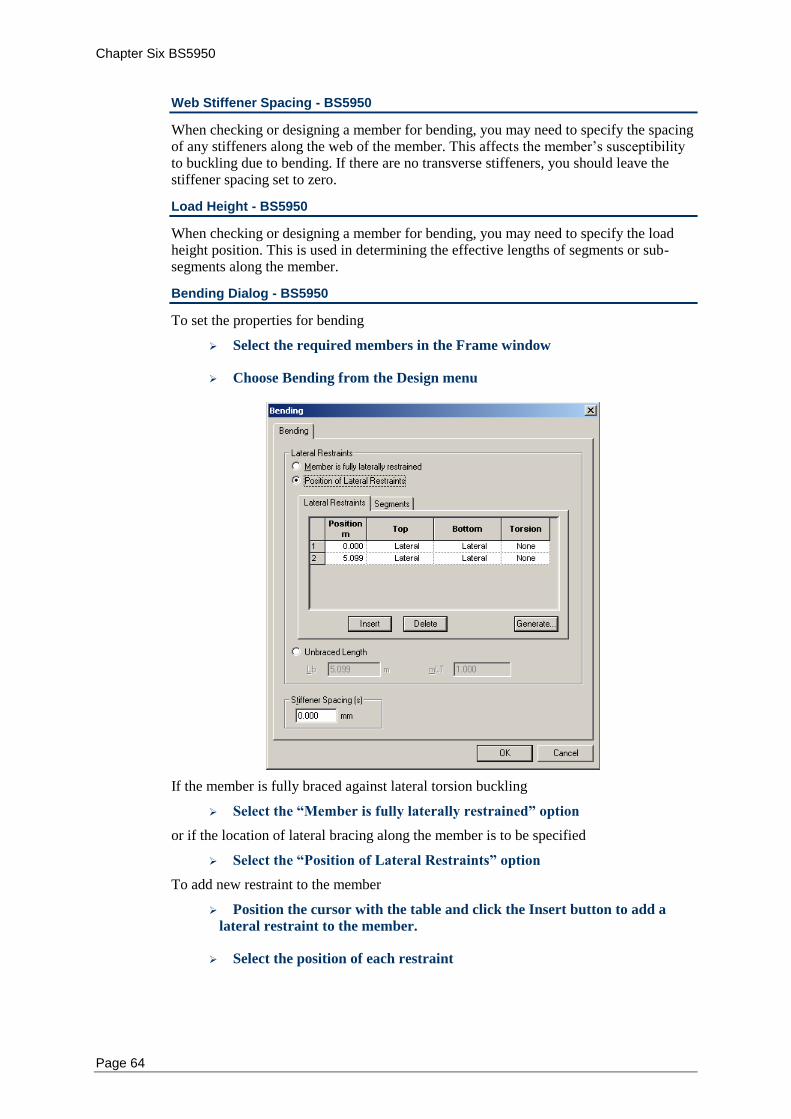
Chapter Six BS5950
Page 64
Web Stiffener Spacing - BS5950
When checking or designing a member for bending, you may need to specify the spacing of any stiffeners along the web of the member. This affects the member’s susceptibility to buckling due to bending. If there are no transverse stiffeners, you should leave the stiffener spacing set to zero.
Load Height - BS5950
When checking or designing a member for bending, you may need to specify the load height position. This is used in determining the effective lengths of segments or sub-segments along the member.
Bending Dialog - BS5950
To set the properties for bending
Select the required members in the Frame window
Choose Bending from the Design menu
If the member is fully braced against lateral torsion buckling
Select the “Member is fully laterally restrained” option
or if the location of lateral bracing along the member is to be specified
Select the “Position of Lateral Restraints” option
To add new restraint to the member
Position the cursor with the table and click the Insert button to add a
lateral restraint to the member.
Select the position of each restraint
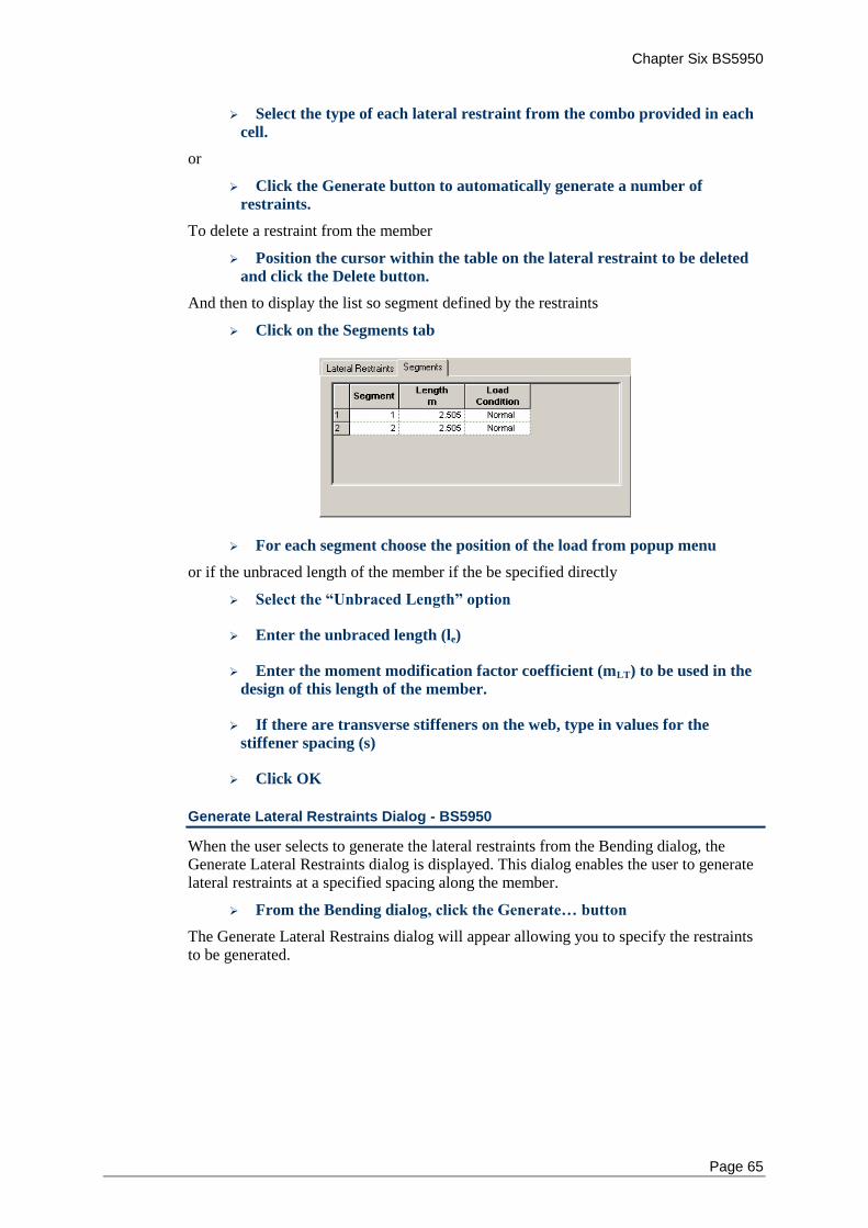
Chapter Six BS5950
Page 65
Select the type of each lateral restraint from the combo provided in each
cell.
or
Click the Generate button to automatically generate a number of
restraints.
To delete a restraint from the member
Position the cursor within the table on the lateral restraint to be deleted
and click the Delete button.
And then to display the list so segment defined by the restraints
Click on the Segments tab
For each segment choose the position of the load from popup menu
or if the unbraced length of the member if the be specified directly
Select the “Unbraced Length” option
Enter the unbraced length (le)
Enter the moment modification factor coefficient (mLT) to be used in the
design of this length of the member.
If there are transverse stiffeners on the web, type in values for the
stiffener spacing (s)
Click OK
Generate Lateral Restraints Dialog - BS5950
When the user selects to generate the lateral restraints from the Bending dialog, the Generate Lateral Restraints dialog is displayed. This dialog enables the user to generate lateral restraints at a specified spacing along the member.
From the Bending dialog, click the Generate… button
The Generate Lateral Restrains dialog will appear allowing you to specify the restraints to be generated.
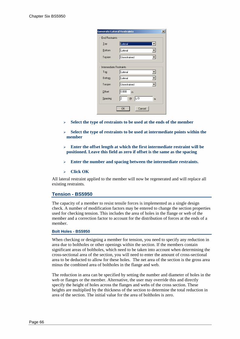
Chapter Six BS5950
Page 66
Select the type of restraints to be used at the ends of the member
Select the type of restraints to be used at intermediate points within the
member
Enter the offset length at which the first intermediate restraint will be
positioned. Leave this field as zero if offset is the same as the spacing
Enter the number and spacing between the intermediate restraints.
Click OK
All lateral restraint applied to the member will now be regenerated and will replace all existing restraints.
Tension - BS5950
The capacity of a member to resist tensile forces is implemented as a single design check. A number of modification factors may be entered to change the section properties used for checking tension. This includes the area of holes in the flange or web of the member and a correction factor to account for the distribution of forces at the ends of a member.
Bolt Holes - BS5950
When checking or designing a member for tension, you need to specify any reduction in area due to boltholes or other openings within the section. If the members contain significant areas of boltholes, which need to be taken into account when determining the cross-sectional area of the section, you will need to enter the amount of cross-sectional area to be deducted to allow for these holes. The net area of the section is the gross area minus the combined area of boltholes in the flange and web. The reduction in area can be specified by setting the number and diameter of holes in the web or flanges or the member. Alternative, the user may override this and directly specify the height of holes across the flanges and webs of the cross section. These heights are multiplied by the thickness of the section to determine the total reduction in area of the section. The initial value for the area of boltholes is zero.
Chapter Six BS5950
Page 67
Area Reduction Coefficient - BS5950
The reduced tensile capacity of members with eccentric connections is specified by clause 4.6.3 of BS5950. Multiframe Steel Codes does not use this clause but instead approximates the tensile capacity using a similar calculation to that specified by Clause 4.6.1 but which includes an extra factor to account for the reduction in area. As such that the tensile capacity is computed in Multiframe Steel Codes using the expression Pt = pyktAe in which kt represents an area reduction coefficient. While this method does not directly represent the calculation of clause 4.6.3.1 it provides a simple method by which to account for the reduced tensile capacity described in this clause. For the tensile capacity expressions of clause 4.6.3 is can be shown that minimum values of kt are
Clause 4.6.3.1 – bolted connections Pt = py(Ae-0.5a2) kt = 0.5
– welded connections Pt = py(Ag-0.3a2) kt = 0.7
Clause 4.6.3.2 – bolted connections Pt = py(Ae-0.25a2) kt = 0.75
– welded connections Pt = py(Ae-0.15a2) kt = 0.85 while less conservative values of kt based upon the gross area of the connected element taken as half the gross are of the section are as follows.
Clause 4.6.3.1 – bolted connections Pt = py(Ae-0.5a2) kt = 0.75
– welded connections Pt = py(Ae-0.3a2) kt = 0.85
Clause 4.6.3.2 – bolted connections Pt = py(Ae-0.25a2) kt = 0.875
– welded connections Pt = py(Ae-0.15a2) kt = 0.925
Tension Dialog - BS5950
To enter the properties for tension
Select the required members in the Frame window
Choose Tension… from the Design menu
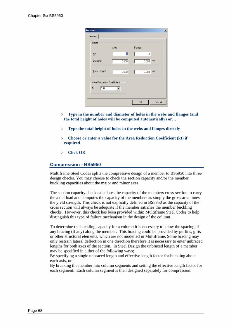
Chapter Six BS5950
Page 68
Type in the number and diameter of holes in the webs and flanges (and
the total height of holes will be computed automatically) or…
Type the total height of holes in the webs and flanges directly
Choose or enter a value for the Area Reduction Coefficient (kt) if
required
Click OK
Compression - BS5950
Multiframe Steel Codes splits the compressive design of a member to BS5950 into three design checks. You may choose to check the section capacity and/or the member buckling capacities about the major and minor axes. The section capacity check calculates the capacity of the members cross-section to carry the axial load and computes the capacity of the members as simply the gross area times the yield strength. This check is not explicitly defined in BS5950 as the capacity of the cross section will always be adequate if the member satisfies the member buckling checks. However, this check has been provided within Multiframe Steel Codes to help distinguish this type of failure mechanism in the design of the column. To determine the buckling capacity for a column it is necessary to know the spacing of any bracing (if any) along the member. This bracing could be provided by purlins, girts or other structural elements, which are not modelled in Multiframe. Some bracing may only restrain lateral deflection in one direction therefore it is necessary to enter unbraced lengths for both axes of the section. In Steel Design the unbraced length of a member may be specified in either of the following ways; By specifying a single unbraced length and effective length factor for buckling about each axis, or By breaking the member into column segments and setting the effective length factor for each segment. Each column segment is then designed separately for compression.
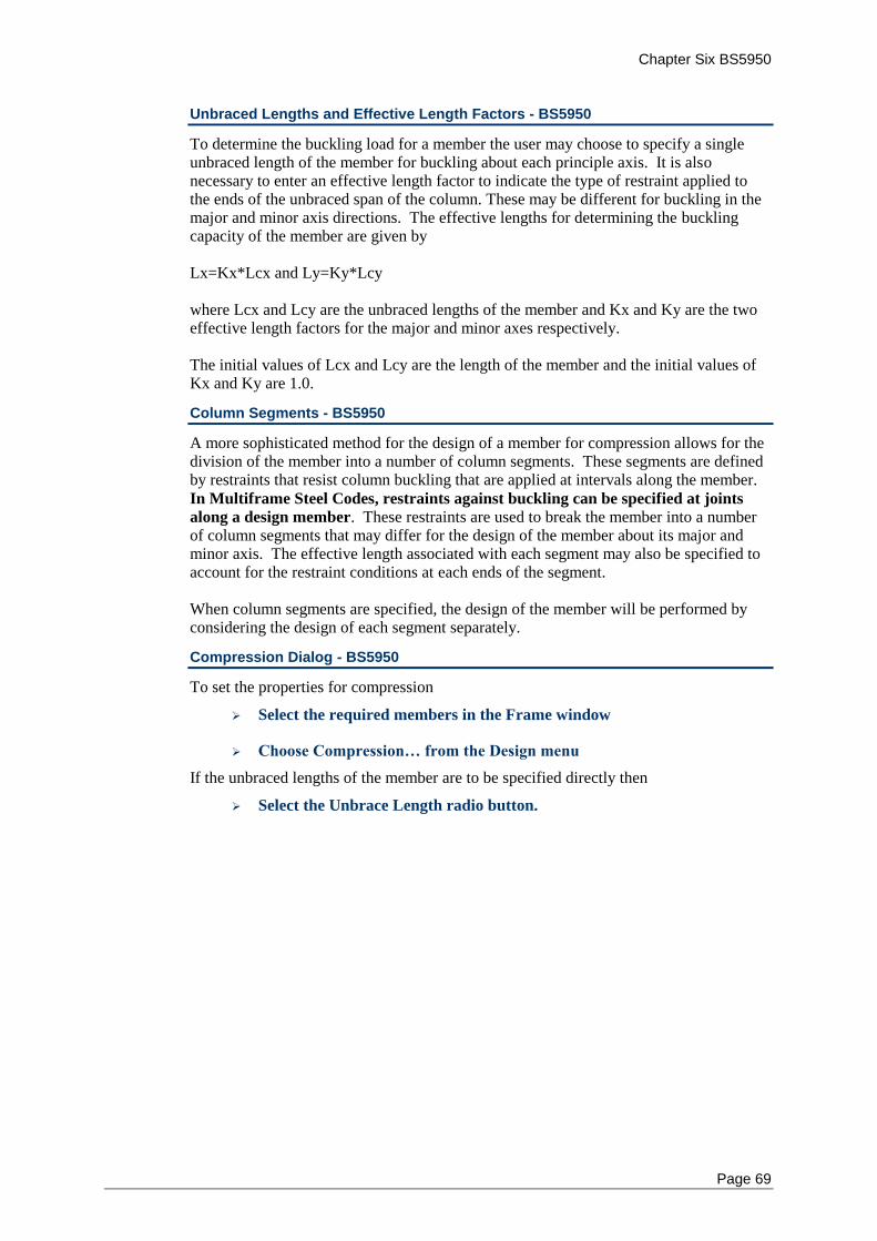
Chapter Six BS5950
Page 69
Unbraced Lengths and Effective Length Factors - BS5950
To determine the buckling load for a member the user may choose to specify a single unbraced length of the member for buckling about each principle axis. It is also necessary to enter an effective length factor to indicate the type of restraint applied to the ends of the unbraced span of the column. These may be different for buckling in the major and minor axis directions. The effective lengths for determining the buckling capacity of the member are given by Lx=Kx*Lcx and Ly=Ky*Lcy where Lcx and Lcy are the unbraced lengths of the member and Kx and Ky are the two effective length factors for the major and minor axes respectively. The initial values of Lcx and Lcy are the length of the member and the initial values of Kx and Ky are 1.0.
Column Segments - BS5950
A more sophisticated method for the design of a member for compression allows for the division of the member into a number of column segments. These segments are defined by restraints that resist column buckling that are applied at intervals along the member.
In Multiframe Steel Codes, restraints against buckling can be specified at joints
along a design member. These restraints are used to break the member into a number of column segments that may differ for the design of the member about its major and minor axis. The effective length associated with each segment may also be specified to account for the restraint conditions at each ends of the segment. When column segments are specified, the design of the member will be performed by considering the design of each segment separately.
Compression Dialog - BS5950
To set the properties for compression
Select the required members in the Frame window
Choose Compression… from the Design menu
If the unbraced lengths of the member are to be specified directly then
Select the Unbrace Length radio button.
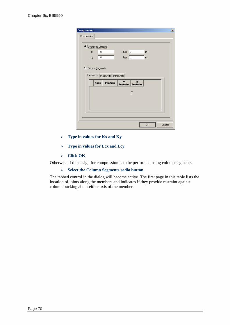
Chapter Six BS5950
Page 70
Type in values for Kx and Ky
Type in values for Lcx and Lcy
Click OK
Otherwise if the design for compression is to be performed using column segments.
Select the Column Segments radio button.
The tabbed control in the dialog will become active. The first page in this table lists the location of joints along the members and indicates if they provide restraint against column bucking about either axis of the member.
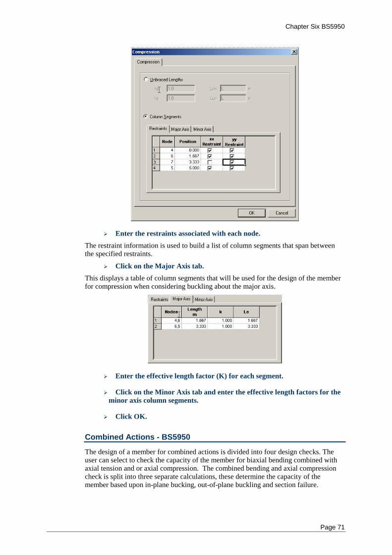
Chapter Six BS5950
Page 71
Enter the restraints associated with each node.
The restraint information is used to build a list of column segments that span between the specified restraints.
Click on the Major Axis tab.
This displays a table of column segments that will be used for the design of the member for compression when considering buckling about the major axis.
Enter the effective length factor (K) for each segment.
Click on the Minor Axis tab and enter the effective length factors for the
minor axis column segments.
Click OK.
Combined Actions - BS5950
The design of a member for combined actions is divided into four design checks. The user can select to check the capacity of the member for biaxial bending combined with axial tension and or axial compression. The combined bending and axial compression check is split into three separate calculations, these determine the capacity of the member based upon in-plane bucking, out-of-plane buckling and section failure.
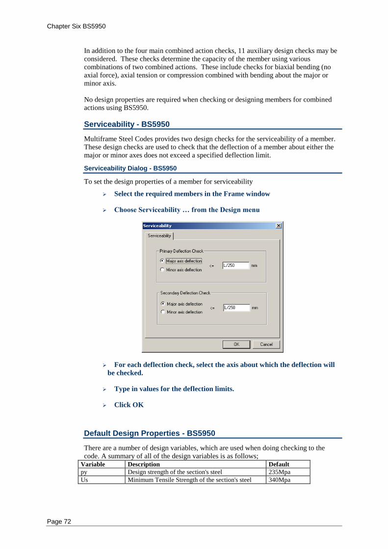
Chapter Six BS5950
Page 72
In addition to the four main combined action checks, 11 auxiliary design checks may be considered. These checks determine the capacity of the member using various combinations of two combined actions. These include checks for biaxial bending (no axial force), axial tension or compression combined with bending about the major or minor axis. No design properties are required when checking or designing members for combined actions using BS5950.
Serviceability - BS5950
Multiframe Steel Codes provides two design checks for the serviceability of a member. These design checks are used to check that the deflection of a member about either the major or minor axes does not exceed a specified deflection limit.
Serviceability Dialog - BS5950
To set the design properties of a member for serviceability
Select the required members in the Frame window
Choose Serviceability … from the Design menu
For each deflection check, select the axis about which the deflection will
be checked.
Type in values for the deflection limits.
Click OK
Default Design Properties - BS5950
There are a number of design variables, which are used when doing checking to the code. A summary of all of the design variables is as follows;
Variable Description Default
py Design strength of the section's steel 235Mpa
Us Minimum Tensile Strength of the section's steel 340Mpa
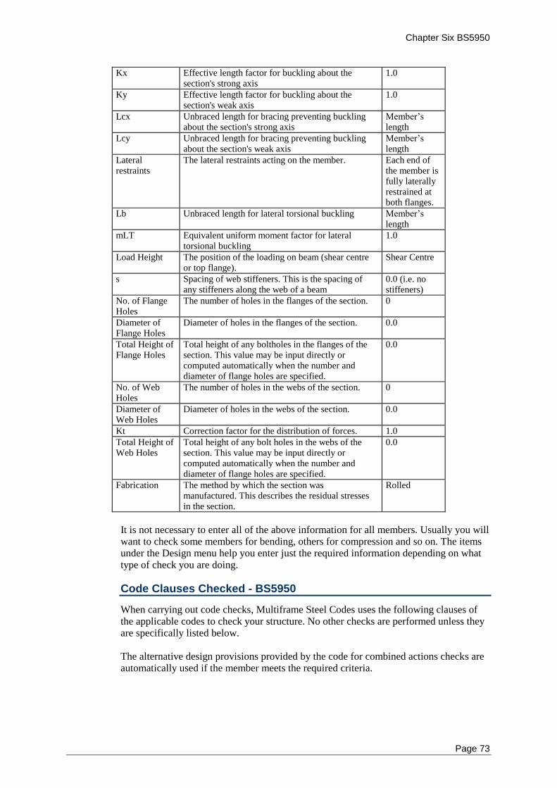
Chapter Six BS5950
Page 73
Kx Effective length factor for buckling about the section's strong axis
1.0
Ky Effective length factor for buckling about the section's weak axis
1.0
Lcx Unbraced length for bracing preventing buckling about the section's strong axis
Member’s length
Lcy Unbraced length for bracing preventing buckling about the section's weak axis
Member’s length
Lateral restraints
The lateral restraints acting on the member. Each end of the member is fully laterally restrained at both flanges.
Lb Unbraced length for lateral torsional buckling Member’s length
mLT Equivalent uniform moment factor for lateral torsional buckling
1.0
Load Height The position of the loading on beam (shear centre or top flange).
Shear Centre
s Spacing of web stiffeners. This is the spacing of any stiffeners along the web of a beam
0.0 (i.e. no stiffeners)
No. of Flange Holes
The number of holes in the flanges of the section. 0
Diameter of Flange Holes
Diameter of holes in the flanges of the section. 0.0
Total Height of Flange Holes
Total height of any boltholes in the flanges of the section. This value may be input directly or computed automatically when the number and diameter of flange holes are specified.
0.0
No. of Web Holes
The number of holes in the webs of the section. 0
Diameter of Web Holes
Diameter of holes in the webs of the section. 0.0
Kt Correction factor for the distribution of forces. 1.0
Total Height of Web Holes
Total height of any bolt holes in the webs of the section. This value may be input directly or computed automatically when the number and diameter of flange holes are specified.
0.0
Fabrication The method by which the section was manufactured. This describes the residual stresses in the section.
Rolled
It is not necessary to enter all of the above information for all members. Usually you will want to check some members for bending, others for compression and so on. The items under the Design menu help you enter just the required information depending on what type of check you are doing.
Code Clauses Checked - BS5950
When carrying out code checks, Multiframe Steel Codes uses the following clauses of the applicable codes to check your structure. No other checks are performed unless they are specifically listed below. The alternative design provisions provided by the code for combined actions checks are automatically used if the member meets the required criteria.
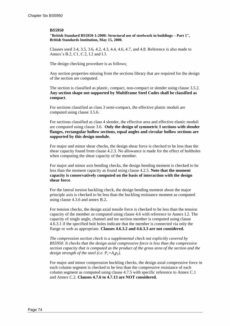
Chapter Six BS5950
Page 74
BS5950
"British Standard BS5950-1:2000: Structural use of steelwork in buildings – Part 1",
British Standards Institution, May 15, 2000.
Clauses used 3.4, 3.5, 3.6, 4.2, 4.3, 4.4, 4.6, 4.7, and 4.8. Reference is also made to Annex’s B.2, C1, C.2, I.2 and I.3. The design checking procedure is as follows; Any section properties missing from the sections library that are required for the design of the section are computed. The section is classified as plastic, compact, non-compact or slender using clause 3.5.2.
Any section shape not supported by Multiframe Steel Codes shall be classified as
compact. For sections classified as class 3 semi-compact, the effective plastic moduli are computed using clause 3.5.6. For sections classified as class 4 slender, the effective area and effective elastic moduli
are computed using clause 3.6. Only the design of symmetric I sections with slender
flanges, rectangular hollow sections, equal angles and circular hollow sections are
supported by this design module. For major and minor shear checks, the design shear force is checked to be less than the shear capacity found from clause 4.2.3. No allowance is made for the effect of boltholes when computing the shear capacity of the member. For major and minor axis bending checks, the design bending moment is checked to be
less than the moment capacity as found using clause 4.2.5. Note that the moment
capacity is conservatively computed on the basis of interaction with the design
shear force. For the lateral torsion buckling check, the design bending moment about the major principle axis is checked to be less than the buckling resistance moment as computed
using clause 4.3.6 and annex B.2. For tension checks, the design axial tensile force is checked to be less than the tension capacity of the member as computed using clause 4.6 with reference to Annex I.2. The capacity of single angle, channel and tee section member is computed using clause 4.6.3.1 if the specified bolt holes indicate that the member is connected via only the
flange or web as appropriate. Clauses 4.6.3.2 and 4.6.3.3 are not considered. The compression section check is a supplemental check not explicitly covered by BS5950. It checks that the design axial compressive force is less than the compressive section capacity that is computed as the product of the gross area of the section and the design strength of the steel (i.e. Pc=Agpy). For major and minor compression buckling checks, the design axial compressive force in each column segment is checked to be less than the compressive resistance of each column segment as computed using clause 4.7.5 with specific reference to Annex C.1
and Annex C.2. Clauses 4.7.6 to 4.7.13 are NOT considered.
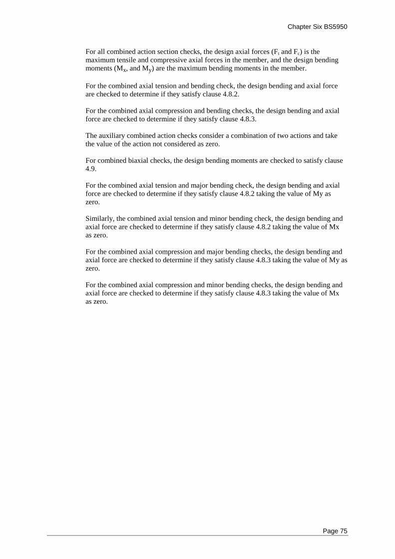
Chapter Six BS5950
Page 75
For all combined action section checks, the design axial forces (Ft and Fc) is the maximum tensile and compressive axial forces in the member, and the design bending moments (Mx, and My) are the maximum bending moments in the member.
For the combined axial tension and bending check, the design bending and axial force are checked to determine if they satisfy clause 4.8.2. For the combined axial compression and bending checks, the design bending and axial force are checked to determine if they satisfy clause 4.8.3. The auxiliary combined action checks consider a combination of two actions and take the value of the action not considered as zero. For combined biaxial checks, the design bending moments are checked to satisfy clause 4.9. For the combined axial tension and major bending check, the design bending and axial force are checked to determine if they satisfy clause 4.8.2 taking the value of My as zero. Similarly, the combined axial tension and minor bending check, the design bending and axial force are checked to determine if they satisfy clause 4.8.2 taking the value of Mx as zero. For the combined axial compression and major bending checks, the design bending and axial force are checked to determine if they satisfy clause 4.8.3 taking the value of My as zero. For the combined axial compression and minor bending checks, the design bending and axial force are checked to determine if they satisfy clause 4.8.3 taking the value of Mx as zero.

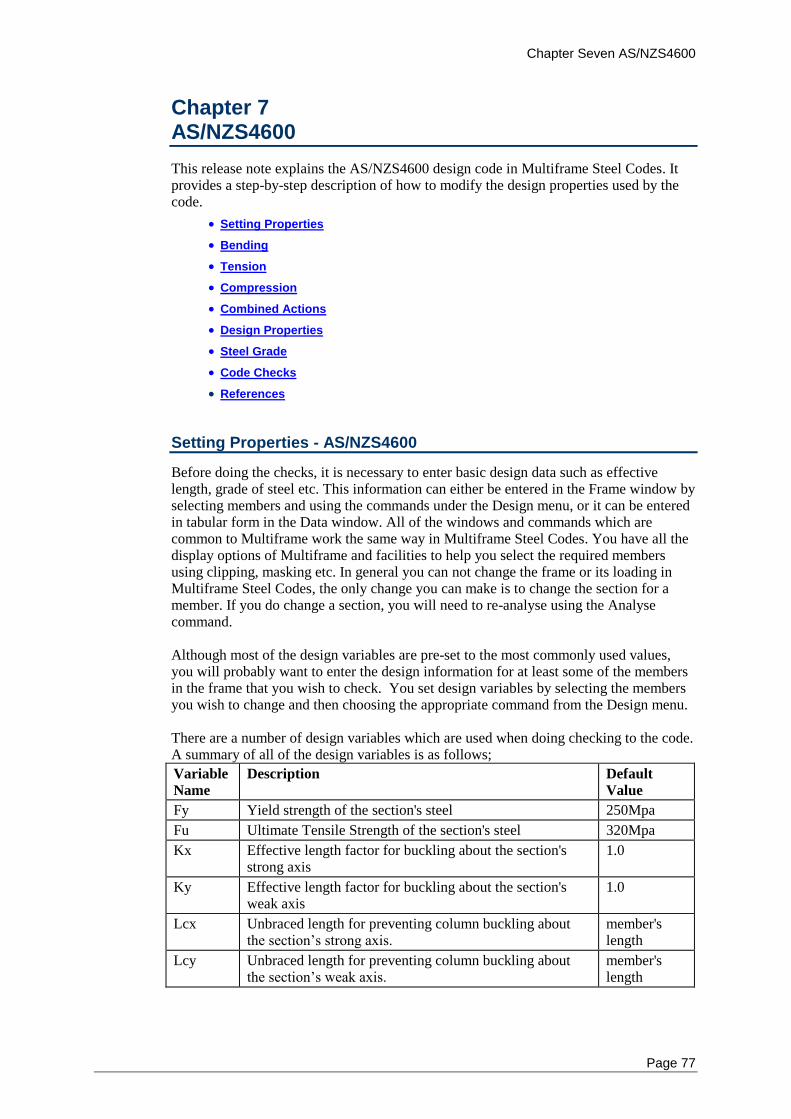
Chapter Seven AS/NZS4600
Page 77
Chapter 7 AS/NZS4600
This release note explains the AS/NZS4600 design code in Multiframe Steel Codes. It provides a step-by-step description of how to modify the design properties used by the code.
Setting Properties
Bending
Tension
Compression
Combined Actions
Design Properties
Steel Grade
Code Checks
References
Setting Properties - AS/NZS4600
Before doing the checks, it is necessary to enter basic design data such as effective length, grade of steel etc. This information can either be entered in the Frame window by selecting members and using the commands under the Design menu, or it can be entered in tabular form in the Data window. All of the windows and commands which are common to Multiframe work the same way in Multiframe Steel Codes. You have all the display options of Multiframe and facilities to help you select the required members using clipping, masking etc. In general you can not change the frame or its loading in Multiframe Steel Codes, the only change you can make is to change the section for a member. If you do change a section, you will need to re-analyse using the Analyse command. Although most of the design variables are pre-set to the most commonly used values, you will probably want to enter the design information for at least some of the members in the frame that you wish to check. You set design variables by selecting the members you wish to change and then choosing the appropriate command from the Design menu. There are a number of design variables which are used when doing checking to the code. A summary of all of the design variables is as follows;
Variable
Name
Description Default
Value
Fy Yield strength of the section's steel 250Mpa
Fu Ultimate Tensile Strength of the section's steel 320Mpa
Kx Effective length factor for buckling about the section's strong axis
1.0
Ky Effective length factor for buckling about the section's weak axis
1.0
Lcx Unbraced length for preventing column buckling about the section’s strong axis.
member's length
Lcy Unbraced length for preventing column buckling about the section’s weak axis.
member's length
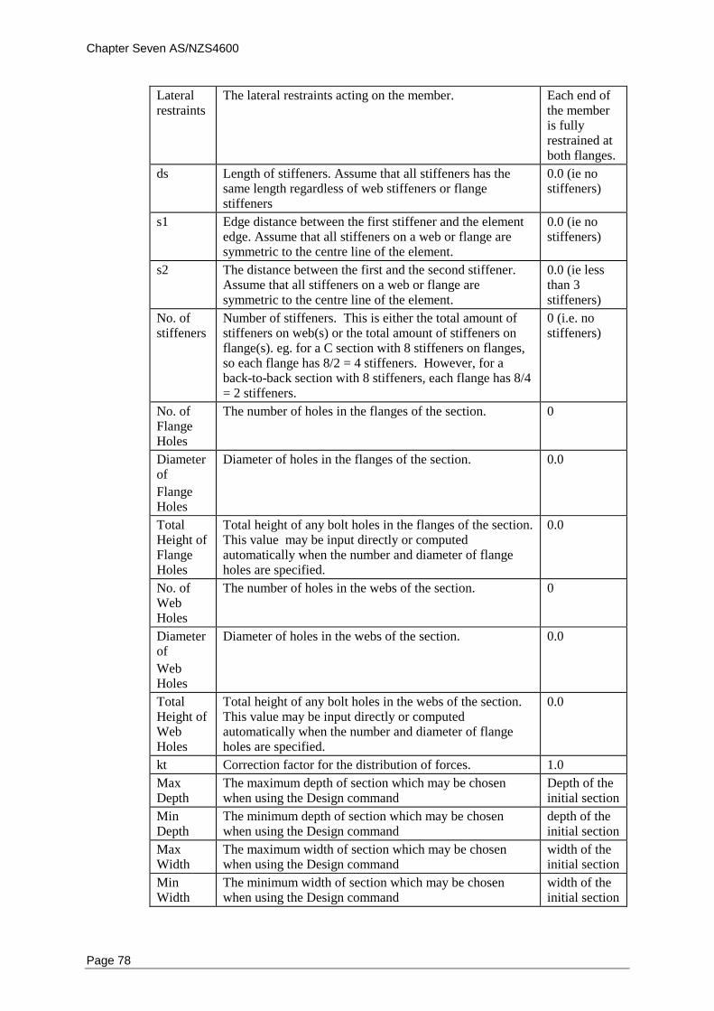
Chapter Seven AS/NZS4600
Page 78
Lateral restraints
The lateral restraints acting on the member. Each end of the member is fully restrained at both flanges.
ds Length of stiffeners. Assume that all stiffeners has the same length regardless of web stiffeners or flange stiffeners
0.0 (ie no stiffeners)
s1 Edge distance between the first stiffener and the element edge. Assume that all stiffeners on a web or flange are symmetric to the centre line of the element.
0.0 (ie no stiffeners)
s2 The distance between the first and the second stiffener. Assume that all stiffeners on a web or flange are symmetric to the centre line of the element.
0.0 (ie less than 3 stiffeners)
No. of stiffeners
Number of stiffeners. This is either the total amount of stiffeners on web(s) or the total amount of stiffeners on flange(s). eg. for a C section with 8 stiffeners on flanges, so each flange has 8/2 = 4 stiffeners. However, for a back-to-back section with 8 stiffeners, each flange has 8/4 = 2 stiffeners.
0 (i.e. no stiffeners)
No. of Flange Holes
The number of holes in the flanges of the section. 0
Diameter of
Flange Holes
Diameter of holes in the flanges of the section. 0.0
Total Height of Flange Holes
Total height of any bolt holes in the flanges of the section. This value may be input directly or computed automatically when the number and diameter of flange holes are specified.
0.0
No. of Web Holes
The number of holes in the webs of the section. 0
Diameter of
Web Holes
Diameter of holes in the webs of the section. 0.0
Total Height of Web Holes
Total height of any bolt holes in the webs of the section. This value may be input directly or computed automatically when the number and diameter of flange holes are specified.
0.0
kt Correction factor for the distribution of forces. 1.0
Max Depth
The maximum depth of section which may be chosen when using the Design command
Depth of the initial section
Min Depth
The minimum depth of section which may be chosen when using the Design command
depth of the initial section
Max Width
The maximum width of section which may be chosen when using the Design command
width of the initial section
Min Width
The minimum width of section which may be chosen when using the Design command
width of the initial section
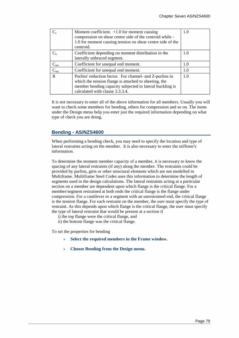
Chapter Seven AS/NZS4600
Page 79
Cs Moment coefficient. +1.0 for moment causing compression on shear centre side of the centroid while -1.0 for moment causing tension on shear centre side of the centroid.
1.0
Cb Coefficient depending on moment distribution in the laterally unbraced segment.
1.0
Cmx Coefficient for unequal end moment. 1.0
Cmy Coefficient for unequal end moment. 1.0
R Purlins' reduction factor. For channel- and Z-purlins in which the tension flange is attached to sheeting, the member bending capacity subjected to lateral buckling is calculated with clause 3.3.3.4.
1.0
It is not necessary to enter all of the above information for all members. Usually you will want to check some members for bending, others for compression and so on. The items under the Design menu help you enter just the required information depending on what type of check you are doing.
Bending - AS/NZS4600
When performing a bending check, you may need to specify the location and type of lateral restraints acting on the member. It is also necessary to enter the stiffener's information. To determine the moment member capacity of a member, it is necessary to know the spacing of any lateral restraints (if any) along the member. The restraints could be provided by purlins, girts or other structural elements which are not modelled in Multiframe. Multiframe Steel Codes uses this information to determine the length of segments used in the design calculations. The lateral restraints acting at a particular section on a member are dependent upon which flange is the critical flange. For a member/segment restrained at both ends the critical flange is the flange under compression. For a cantilever or a segment with an unrestrained end, the critical flange is the tension flange. For each restraint on the member, the user must specify the type of restraint. As this depends upon which flange is the critical flange, the user must specify the type of lateral restraint that would be present at a section if i) the top flange were the critical flange, and ii) the bottom flange was the critical flange.
To set the properties for bending
Select the required members in the Frame window.
Choose Bending from the Design menu.
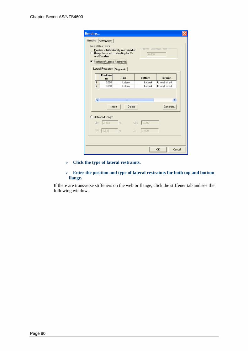
Chapter Seven AS/NZS4600
Page 80
Click the type of lateral restraints.
Enter the position and type of lateral restraints for both top and bottom
flange.
If there are transverse stiffeners on the web or flange, click the stiffener tab and see the following window.
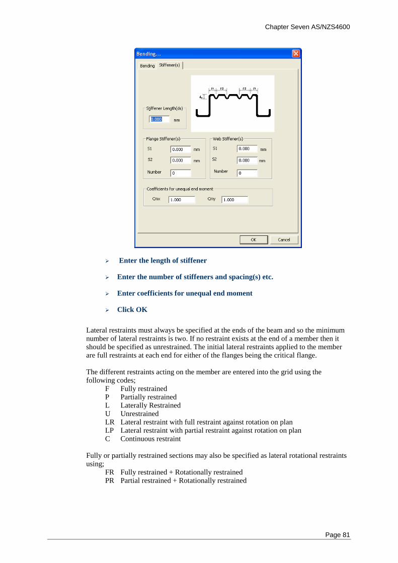
Chapter Seven AS/NZS4600
Page 81
Enter the length of stiffener
Enter the number of stiffeners and spacing(s) etc.
Enter coefficients for unequal end moment
Click OK
Lateral restraints must always be specified at the ends of the beam and so the minimum number of lateral restraints is two. If no restraint exists at the end of a member then it should be specified as unrestrained. The initial lateral restraints applied to the member are full restraints at each end for either of the flanges being the critical flange. The different restraints acting on the member are entered into the grid using the following codes;
F Fully restrained P Partially restrained L Laterally Restrained U Unrestrained LR Lateral restraint with full restraint against rotation on plan LP Lateral restraint with partial restraint against rotation on plan C Continuous restraint
Fully or partially restrained sections may also be specified as lateral rotational restraints using;
FR Fully restrained + Rotationally restrained PR Partial restrained + Rotationally restrained
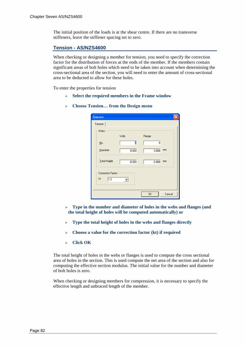
Chapter Seven AS/NZS4600
Page 82
The initial position of the loads is at the shear centre. If there are no transverse stiffeners, leave the stiffener spacing set to zero.
Tension - AS/NZS4600
When checking or designing a member for tension, you need to specify the correction factor for the distribution of forces at the ends of the member. If the members contain significant areas of bolt holes which need to be taken into account when determining the cross-sectional area of the section, you will need to enter the amount of cross-sectional area to be deducted to allow for these holes. To enter the properties for tension
Select the required members in the Frame window
Choose Tension… from the Design menu
Type in the number and diameter of holes in the webs and flanges (and
the total height of holes will be computed automatically) or
Type the total height of holes in the webs and flanges directly
Choose a value for the correction factor (kt) if required
Click OK
The total height of holes in the webs or flanges is used to compute the cross sectional area of holes in the section. This is used compute the net area of the section and also for computing the effective section modulus. The initial value for the number and diameter of bolt holes is zero. When checking or designing members for compression, it is necessary to specify the effective length and unbraced length of the member.
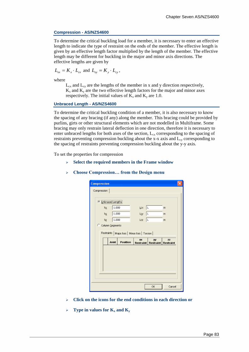
Chapter Seven AS/NZS4600
Page 83
Compression - AS/NZS4600
To determine the critical buckling load for a member, it is necessary to enter an effective length to indicate the type of restraint on the ends of the member. The effective length is given by an effective length factor multiplied by the length of the member. The effective length may be different for buckling in the major and minor axis directions. The effective lengths are given by
cxxex LKL and cyyey LKL ,
where Lcx and Lcy are the lengths of the member in x and y direction respectively, Kx and Ky are the two effective length factors for the major and minor axes respectively. The initial values of Kx and Ky are 1.0.
Unbraced Length - AS/NZS4600
To determine the critical buckling condition of a member, it is also necessary to know the spacing of any bracing (if any) along the member. This bracing could be provided by purlins, girts or other structural elements which are not modelled in Multiframe. Some bracing may only restrain lateral deflection in one direction, therefore it is necessary to enter unbraced lengths for both axes of the section, Lcx corresponding to the spacing of restraints preventing compression buckling about the x-x axis and Lcy corresponding to the spacing of restraints preventing compression buckling about the y-y axis. To set the properties for compression
Select the required members in the Frame window
Choose Compression… from the Design menu
Click on the icons for the end conditions in each direction or
Type in values for Kx and Ky
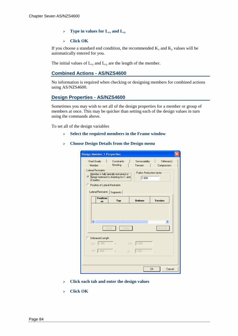
Chapter Seven AS/NZS4600
Page 84
Type in values for Lcx and Lcy
Click OK
If you choose a standard end condition, the recommended Kx and Ky values will be automatically entered for you. The initial values of Lcx and Lcy are the length of the member.
Combined Actions - AS/NZS4600
No information is required when checking or designing members for combined actions using AS/NZS4600.
Design Properties - AS/NZS4600
Sometimes you may wish to set all of the design properties for a member or group of members at once. This may be quicker than setting each of the design values in turn using the commands above. To set all of the design variables
Select the required members in the Frame window
Choose Design Details from the Design menu
Click each tab and enter the design values
Click OK
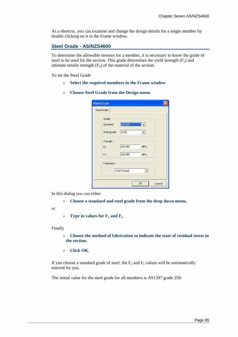
Chapter Seven AS/NZS4600
Page 85
As a shortcut, you can examine and change the design details for a single member by double clicking on it in the Frame window.
Steel Grade - AS/NZS4600
To determine the allowable stresses for a member, it is necessary to know the grade of steel to be used for the section. This grade determines the yield strength (Fy) and ultimate tensile strength (Fu) of the material of the section. To set the Steel Grade
Select the required members in the Frame window
Choose Steel Grade from the Design menu
In this dialog you can either
Choose a standard and steel grade from the drop down menu,
or
Type in values for Fy and Fu.
Finally
Choose the method of fabrication to indicate the state of residual stress in
the section.
Click OK.
If you choose a standard grade of steel, the Fy and Fu values will be automatically entered for you. The initial value for the steel grade for all members is AS1397 grade 250.
Chapter Seven AS/NZS4600
Page 86
Code Checks - AS/NZS4600
When carrying out code checks to AS/NZS4600, Multiframe Steel Codes uses the following clauses of to check your structure. No other checks are performed unless they are specifically listed below. AS/NZS 4600: "Australian/New Zealand Standard AS/NZS4600-2005: Cold-formed Steel
Structures", Standards Australia, 30 December, 2005.
Clauses used are 3.1~3.5.
Design Checking Procedure
The design checking procedure is as follows; The design actions are calculated through the first order analyses and a second order analysis should be used for sway frames. For major and minor bending section checks, the design bending moment is checked to be less than the nominal section moment design capacity as found using clause 3.3.2. For bending member checks, the design bending moment about the major principle axis is checked to be less than the nominal member moment design capacity as found using clause 3.3.3. For some section shapes, the bending of distortional buckling check may not be included: clause 3.3.3.3. For major and minor shear checks, the design shear force is checked to be less than the nominal shear capacity found from section 3.3.4. For tension checks, the design axial tension force is checked to be less than the nominal section design capacity in tension as computed using clause 3.2. For compression section checks, the design axial compressive force is checked to be less than the nominal section design capacity in compression as computed using clause 3.4.1. For major and minor compression member checks, the design axial compressive force is checked to be less than the nominal member design capacity in compression as computed using clause 3.4.2~3.4.5. For all combined action section checks, the design axial force (N*) is the maximum axial force in the member, and the design bending moments (Mx*, and My*) are the maximum bending moments in the member. For major and minor combined section checks, the design bending moment is checked to be less than the nominal section moment design capacity reduced by axial force (compression or tension) as computed using clause 3.5.1.
References - AS/NZS4600
You may find the following books useful to refer to if you need information on the methods used to check members in Multiframe Steel Codes. • Australian/New Zealand Standard AS/NZS 4600:2005, Cold-formed Steel Structures,
Australian Institute of Steel Construction, Sydney, 1998, 3rd Edition
Chapter Seven AS/NZS4600
Page 87
• Design of Cold-formed Steel Structures (to Australian/New Zealand Standard AS/NZS
4600:1996), J. Handcock, Australian Institute of Steel Construction, Sydney, 1998, 3rd
Edition
• Design of Cold-formed Steel Members, J. Rhodes, Department of Mechanical
Engineering, University of Strathclyde, Glasgow, UK, 1991
• Multiframe Steel Codess Handbook, B.Gorenc, R. Tinyou and A. Syam, UNSW Press,
Sydney, 1996, 6th Edition
• The Behaviour and Design of Steel Structures, N S Trahair and M A Bradford,
Chapman and Hall, London, 1988

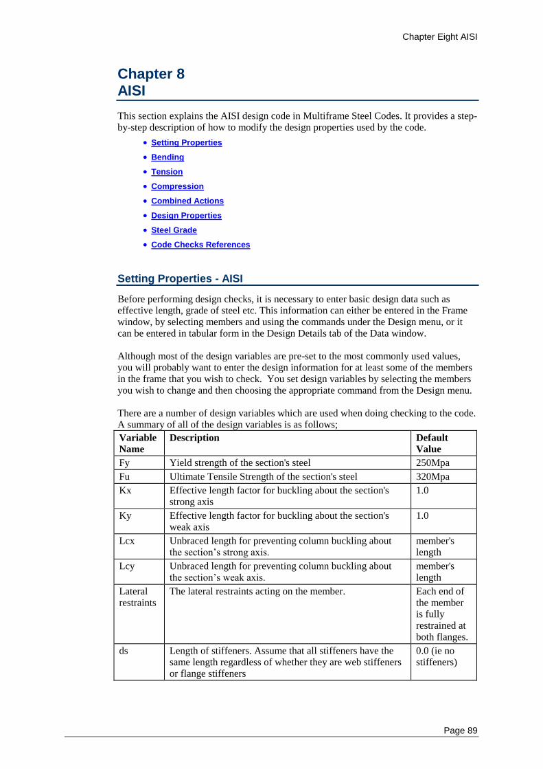
Chapter Eight AISI
Page 89
Chapter 8 AISI
This section explains the AISI design code in Multiframe Steel Codes. It provides a step-by-step description of how to modify the design properties used by the code.
Setting Properties
Bending
Tension
Compression
Combined Actions
Design Properties
Steel Grade
Code Checks References
Setting Properties - AISI
Before performing design checks, it is necessary to enter basic design data such as effective length, grade of steel etc. This information can either be entered in the Frame window, by selecting members and using the commands under the Design menu, or it can be entered in tabular form in the Design Details tab of the Data window. Although most of the design variables are pre-set to the most commonly used values, you will probably want to enter the design information for at least some of the members in the frame that you wish to check. You set design variables by selecting the members you wish to change and then choosing the appropriate command from the Design menu. There are a number of design variables which are used when doing checking to the code. A summary of all of the design variables is as follows;
Variable
Name
Description Default
Value
Fy Yield strength of the section's steel 250Mpa
Fu Ultimate Tensile Strength of the section's steel 320Mpa
Kx Effective length factor for buckling about the section's strong axis
1.0
Ky Effective length factor for buckling about the section's weak axis
1.0
Lcx Unbraced length for preventing column buckling about the section’s strong axis.
member's length
Lcy Unbraced length for preventing column buckling about the section’s weak axis.
member's length
Lateral restraints
The lateral restraints acting on the member. Each end of the member is fully restrained at both flanges.
ds Length of stiffeners. Assume that all stiffeners have the same length regardless of whether they are web stiffeners or flange stiffeners
0.0 (ie no stiffeners)
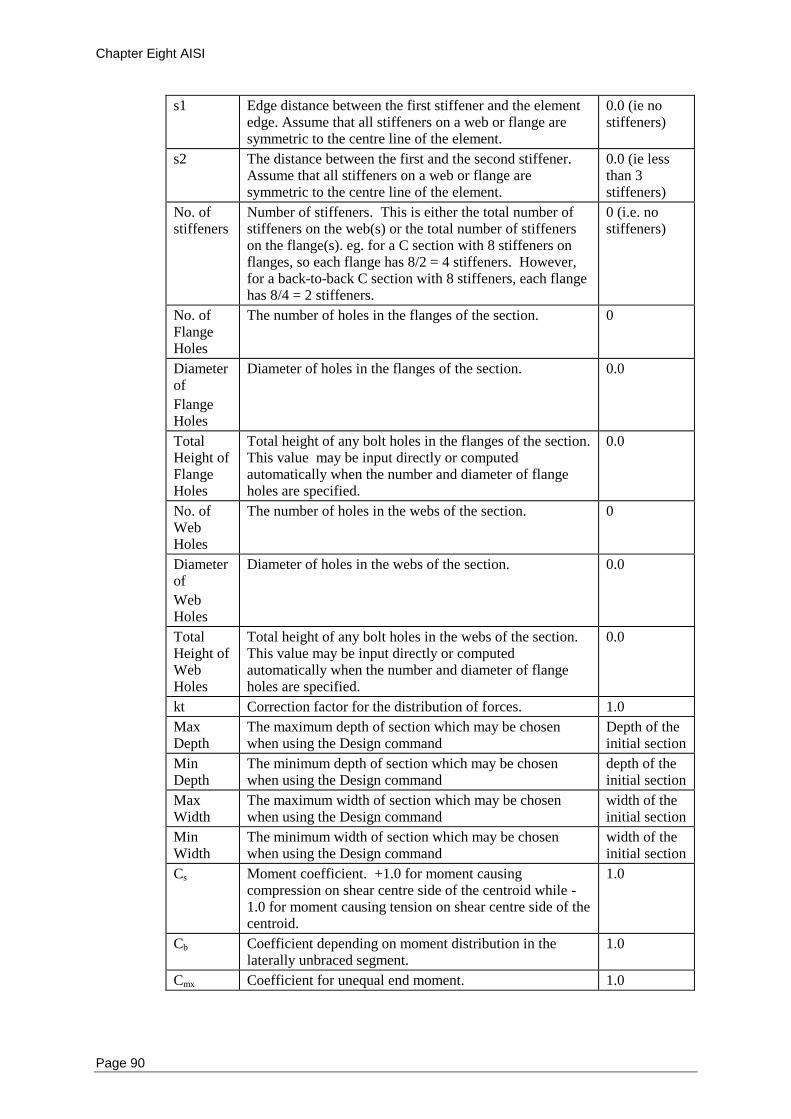
Chapter Eight AISI
Page 90
s1 Edge distance between the first stiffener and the element edge. Assume that all stiffeners on a web or flange are symmetric to the centre line of the element.
0.0 (ie no stiffeners)
s2 The distance between the first and the second stiffener. Assume that all stiffeners on a web or flange are symmetric to the centre line of the element.
0.0 (ie less than 3 stiffeners)
No. of stiffeners
Number of stiffeners. This is either the total number of stiffeners on the web(s) or the total number of stiffeners on the flange(s). eg. for a C section with 8 stiffeners on flanges, so each flange has 8/2 = 4 stiffeners. However, for a back-to-back C section with 8 stiffeners, each flange has 8/4 = 2 stiffeners.
0 (i.e. no stiffeners)
No. of Flange Holes
The number of holes in the flanges of the section. 0
Diameter of
Flange Holes
Diameter of holes in the flanges of the section. 0.0
Total Height of Flange Holes
Total height of any bolt holes in the flanges of the section. This value may be input directly or computed automatically when the number and diameter of flange holes are specified.
0.0
No. of Web Holes
The number of holes in the webs of the section. 0
Diameter of
Web Holes
Diameter of holes in the webs of the section. 0.0
Total Height of Web Holes
Total height of any bolt holes in the webs of the section. This value may be input directly or computed automatically when the number and diameter of flange holes are specified.
0.0
kt Correction factor for the distribution of forces. 1.0
Max Depth
The maximum depth of section which may be chosen when using the Design command
Depth of the initial section
Min Depth
The minimum depth of section which may be chosen when using the Design command
depth of the initial section
Max Width
The maximum width of section which may be chosen when using the Design command
width of the initial section
Min Width
The minimum width of section which may be chosen when using the Design command
width of the initial section
Cs Moment coefficient. +1.0 for moment causing compression on shear centre side of the centroid while -1.0 for moment causing tension on shear centre side of the centroid.
1.0
Cb Coefficient depending on moment distribution in the laterally unbraced segment.
1.0
Cmx Coefficient for unequal end moment. 1.0
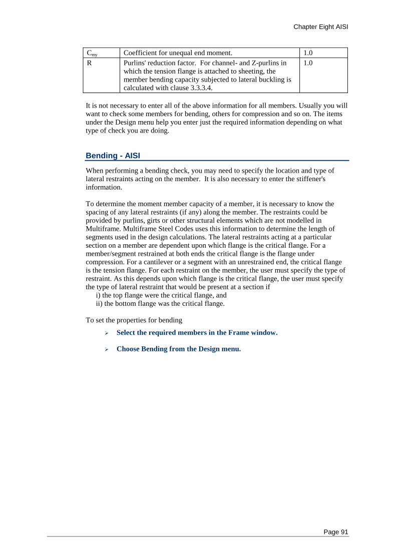
Chapter Eight AISI
Page 91
Cmy Coefficient for unequal end moment. 1.0
R Purlins' reduction factor. For channel- and Z-purlins in which the tension flange is attached to sheeting, the member bending capacity subjected to lateral buckling is calculated with clause 3.3.3.4.
1.0
It is not necessary to enter all of the above information for all members. Usually you will want to check some members for bending, others for compression and so on. The items under the Design menu help you enter just the required information depending on what type of check you are doing.
Bending - AISI
When performing a bending check, you may need to specify the location and type of lateral restraints acting on the member. It is also necessary to enter the stiffener's information. To determine the moment member capacity of a member, it is necessary to know the spacing of any lateral restraints (if any) along the member. The restraints could be provided by purlins, girts or other structural elements which are not modelled in Multiframe. Multiframe Steel Codes uses this information to determine the length of segments used in the design calculations. The lateral restraints acting at a particular section on a member are dependent upon which flange is the critical flange. For a member/segment restrained at both ends the critical flange is the flange under compression. For a cantilever or a segment with an unrestrained end, the critical flange is the tension flange. For each restraint on the member, the user must specify the type of restraint. As this depends upon which flange is the critical flange, the user must specify the type of lateral restraint that would be present at a section if i) the top flange were the critical flange, and ii) the bottom flange was the critical flange.
To set the properties for bending
Select the required members in the Frame window.
Choose Bending from the Design menu.
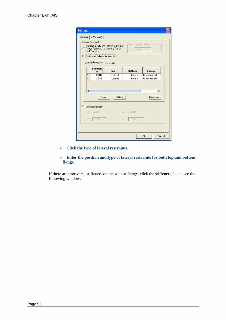
Chapter Eight AISI
Page 92
Click the type of lateral restraints.
Enter the position and type of lateral restraints for both top and bottom
flange.
If there are transverse stiffeners on the web or flange, click the stiffener tab and see the following window.
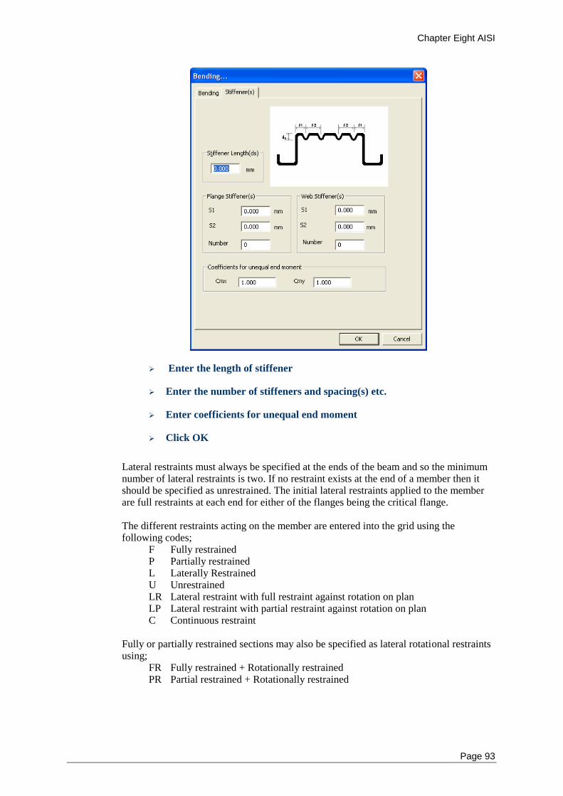
Chapter Eight AISI
Page 93
Enter the length of stiffener
Enter the number of stiffeners and spacing(s) etc.
Enter coefficients for unequal end moment
Click OK
Lateral restraints must always be specified at the ends of the beam and so the minimum number of lateral restraints is two. If no restraint exists at the end of a member then it should be specified as unrestrained. The initial lateral restraints applied to the member are full restraints at each end for either of the flanges being the critical flange. The different restraints acting on the member are entered into the grid using the following codes;
F Fully restrained P Partially restrained L Laterally Restrained U Unrestrained LR Lateral restraint with full restraint against rotation on plan LP Lateral restraint with partial restraint against rotation on plan C Continuous restraint
Fully or partially restrained sections may also be specified as lateral rotational restraints using;
FR Fully restrained + Rotationally restrained PR Partial restrained + Rotationally restrained
Chapter Eight AISI
Page 94
The initial position of the loads is at the shear centre. If there are no transverse stiffeners, leave the stiffener spacing set to zero.
Tension - AISI
When checking or designing a member for tension, you need to specify the correction factor for the distribution of forces at the ends of the member. If the members contain significant areas of bolt holes which need to be taken into account when determining the cross-sectional area of the section, you will need to enter the amount of cross-sectional area to be deducted to allow for these holes. To enter the properties for tension
Select the required members in the Frame window
Choose Tension… from the Design menu
Type in the number and diameter of holes in the webs and flanges (and
the total height of holes will be computed automatically) or
Type the total height of holes in the webs and flanges directly
Choose a value for the correction factor (kt) if required
Click OK
The total height of holes in the webs or flanges is used to compute the cross sectional area of holes in the section. This is used compute the net area of the section and also for computing the effective section modulus. The initial value for the number and diameter of bolt holes is zero. When checking or designing members for compression, it is necessary to specify the effective length and unbraced length of the member.
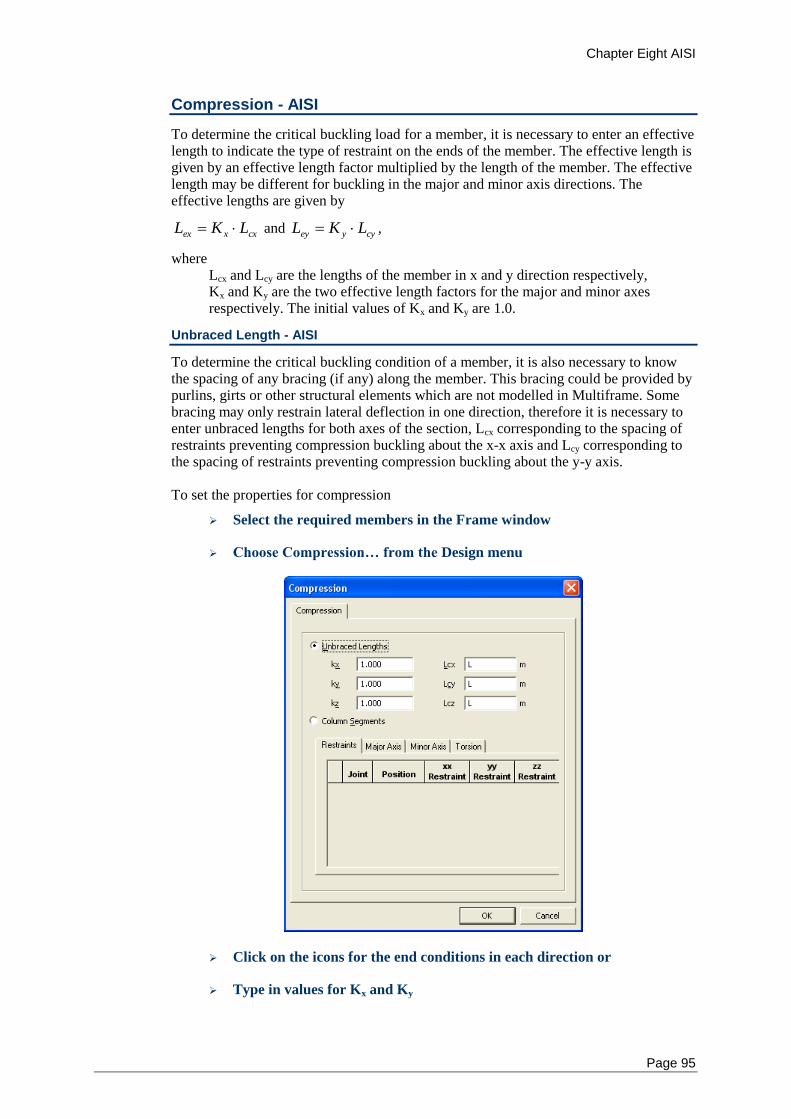
Chapter Eight AISI
Page 95
Compression - AISI
To determine the critical buckling load for a member, it is necessary to enter an effective length to indicate the type of restraint on the ends of the member. The effective length is given by an effective length factor multiplied by the length of the member. The effective length may be different for buckling in the major and minor axis directions. The effective lengths are given by
cxxex LKL and cyyey LKL ,
where Lcx and Lcy are the lengths of the member in x and y direction respectively, Kx and Ky are the two effective length factors for the major and minor axes respectively. The initial values of Kx and Ky are 1.0.
Unbraced Length - AISI
To determine the critical buckling condition of a member, it is also necessary to know the spacing of any bracing (if any) along the member. This bracing could be provided by purlins, girts or other structural elements which are not modelled in Multiframe. Some bracing may only restrain lateral deflection in one direction, therefore it is necessary to enter unbraced lengths for both axes of the section, Lcx corresponding to the spacing of restraints preventing compression buckling about the x-x axis and Lcy corresponding to the spacing of restraints preventing compression buckling about the y-y axis. To set the properties for compression
Select the required members in the Frame window
Choose Compression… from the Design menu
Click on the icons for the end conditions in each direction or
Type in values for Kx and Ky
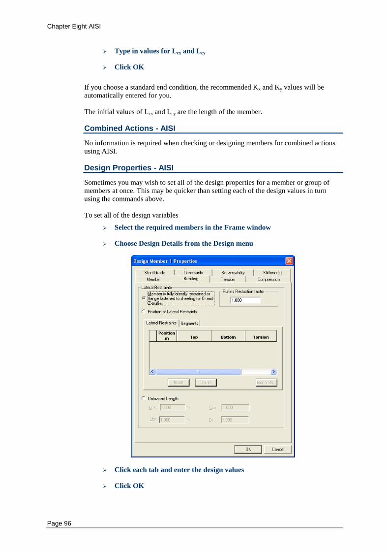
Chapter Eight AISI
Page 96
Type in values for Lcx and Lcy
Click OK
If you choose a standard end condition, the recommended Kx and Ky values will be automatically entered for you. The initial values of Lcx and Lcy are the length of the member.
Combined Actions - AISI
No information is required when checking or designing members for combined actions using AISI.
Design Properties - AISI
Sometimes you may wish to set all of the design properties for a member or group of members at once. This may be quicker than setting each of the design values in turn using the commands above. To set all of the design variables
Select the required members in the Frame window
Choose Design Details from the Design menu
Click each tab and enter the design values
Click OK
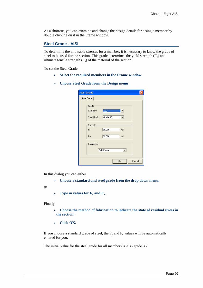
Chapter Eight AISI
Page 97
As a shortcut, you can examine and change the design details for a single member by double clicking on it in the Frame window.
Steel Grade - AISI
To determine the allowable stresses for a member, it is necessary to know the grade of steel to be used for the section. This grade determines the yield strength (Fy) and ultimate tensile strength (Fu) of the material of the section. To set the Steel Grade
Select the required members in the Frame window
Choose Steel Grade from the Design menu
In this dialog you can either
Choose a standard and steel grade from the drop down menu,
or
Type in values for Fy and Fu.
Finally
Choose the method of fabrication to indicate the state of residual stress in
the section.
Click OK.
If you choose a standard grade of steel, the Fy and Fu values will be automatically entered for you. The initial value for the steel grade for all members is A36 grade 36.
Chapter Eight AISI
Page 98
Code Checks - AISI
When carrying out code checks to AISI, Multiframe Steel Codes uses the following clauses of to check your structure. No other checks are performed unless they are specifically listed below. AISI: “North American Specification for the Design of Cold-formed Steel Structural
Members ", AISI Standards, 2001 Edition.
Clauses used are C2~C5.
Design Checking Procedure
The design checking procedure is as follows; The design actions are calculated through the first order analyses and a second order analysis should be used for sway frames. For major and minor bending section checks, the design bending moment is checked to be less than the nominal section moment design capacity as found using clause C3. For bending member checks, the design bending moment about the major principle axis is checked to be less than the nominal member moment design capacity as found using clause C3.1. For major and minor shear checks, the design shear force is checked to be less than the nominal shear capacity found from section C3.2. For tension checks, the design axial tension force is checked to be less than the nominal section design capacity in tension as computed using clause C2. For compression section checks, the design axial compressive force is checked to be less than the nominal section design capacity in compression as computed using clause C4. For major and minor compression member checks, the design axial compressive force is checked to be less than the nominal member design capacity in compression as computed using clause C4.1~C4.6. For all combined action section checks, the design axial force (P*) is the maximum axial force in the member, and the design bending moments (Mx*, and My*) are the maximum bending moments in the member. For major and minor combined section checks, the design bending moment is checked to be less than the nominal section moment design capacity reduced by axial force (compression or tension) as computed using clause C5.
References - AISI
You may find the following books useful to refer to if you need information on the methods used to check members in Multiframe Steel Codes. • Cold-formed Steel Design, Wei-Wen Yu, John Wiley & Sons, Inc., New York, 2000, 3rd
Edition
• Design of Cold-formed Steel Structures to the AISI Specification, Gregory J. Handcock,
Thomas M. Murray and Duane S. Ellifritt, Marcel Dekker, Inc., New York, 2001
Chapter Eight AISI
Page 99
• Design of Cold-formed Steel Members, J. Rhodes, Department of Mechanical
Engineering, University of Strathclyde, Glasgow, UK, 1991
• Multiframe Steel Codess Handbook, B.Gorenc, R. Tinyou and A. Syam, UNSW Press,
Sydney, 1996, 6th Edition
• The Behaviour and Design of Steel Structures, N S Trahair and M A Bradford,
Chapman and Hall, London, 1988

Chapter Five LRFD code
Page 101
Chapter 9 AISC 2005/2010
This chapter describes the implementation of the AISC “Specification for Structural Steel Buildings” within Multiframe Steel Codes. It provides a step-by-step description of how to modify the design properties used by the code. The AISC 2005 is a single, unified structural design code replacing the previously separate Load and Resistance Factor Design (LRFD) and Allowable Stress Design (ASD) codes. The only differences between the application of these two codes are in the use of design capacity factors and for the calculation of Cb for the use in calculation of resistance to biaxial bending combined with a axial force. The updated AISC 2010 code is also implemented. In the LRFD version of the code the allowable strength is given by
Pc = Pn
Where is the resistance factor (always less than 1.0) Pn the design strength For ASD calculations the allowable strength is given by
Pc = Pn /
Where is the safety factor (always greater than 1.0) Pn the design strength
Values for resistance factors ( – LRFD) and safety factors ( – ASD) for the various strength checks are set in Multiframe Steel Codes.
Notation
Design Checks
Bending
Tension
Compression
Combined Actions
Serviceability
Default Design Properties
Code Clauses Checked
Notation – AISC 2005/2010
The notation used in Multiframe Steel Codes generally follows that used in the AISC design code. Use has been made of subscripts to clarify the axis of the member to which a quantity refers. For example, the nominal flexural strengths about the X and Y axes are denoted Mnx and Mny respectively. The geometric axes of a member are denoted as the X and Y axes where X represented the horizontal axis of the member and Y the vertical axis of the member. For design to AISC 2005, it is assumed that the X axis is the major axis and Y is the minor axis.
Chapter Five LRFD
Page 102
Design Checks - AISC 2005/2010
The types of checks are grouped into the categories; Bending, Tension, Compression, Combined and Serviceability. The user may specify which of these checks are performed when a member is designed or checked using Multiframe Steel Codes.
Bending - AISC 2005/2010
The design of a member for bending is divided into four design checks. These check the flexural and shear capacity of the member about the major and minor axes. Each of these checks may consider one or more limit states depending upon the section and the actions within the member. When performing a bending check it is necessary to specify how lateral buckling of the member is resisted. Restraint could be provided by other members, purlins, girts or by other structural elements that are not modelled in Multiframe such as concrete slabs. Multiframe Steel Codes provides three methods of specifying how a member is restrained against lateral buckling. The user may specify That the member is fully restrained against lateral buckling in which case no lateral buckling checks will be performed. The location and type of lateral restraints applied to the member in which case Multiframe Steel Codes will appropriately divide the member into a number of spans and consider the capacity of each of these spans in determining the capacity of the member. Alternatively the laterally unbraced length (Lb) can be specified. You may need to specify a number of properties relating to the location and type of lateral restraints and the stiffener spacing along the member
Lateral Restraints - AISC 2005/2010
If the spacing of lateral restraints along the member is specified, Multiframe Steel Codes uses this information to break the member up into a number of spans in order to determine lateral torsion buckling capacity of each span. In Multiframe Steel Codes, these spans are known as segments.
Each lateral restraint specified by the user is assumed to provide bracing against lateral displacement of the critical flange and/or prevent twist of the cross section. At any cross section, the critical flange is the flange that, in the absence of any restraint at that cross section, would deflect the furthest during buckling of the member. In most members the critical flange will be the compression flange. However for a cantilevered member, the critical flange is the tension flange. For each restraint located along a member, the user must specify the type of restraint. As this depends upon which flange is the critical flange, which is not know a priori, the user must specify the type of lateral restraint that would be present at a section if
The top flange was the critical flange, and
The bottom flange was the critical flange.
In AISC 2005 no distinction is made between different types of lateral restraints. However, to be compatible with other design codes, Multiframe Steel Codes allows for lateral restraints at a cross section to be classified as follows
Chapter Five LRFD code
Page 103
Full Restraint –supports the cross section against lateral displacement of the
critical flange and prevents twist of the cross section.
Partial Restraint – provides support against lateral displacement of the section at a
point other than the critical flange and prevents twist of the cross section.
Lateral Restraint – resists lateral displacement of the critical flange only.
For the purpose of design in AISC 2005/2010, each of these restraint types is consider adequate to provide lateral support to the cross section at which they are applied. Lateral restraints must always be specified at the ends of the beam and so the minimum number of lateral restraints is two. If no restraint exists at the end of a member then it should be specified as unrestrained in which case the member would be regarded as a cantilever. The initial lateral restraints applied to the member are full restraints at each end for either of the flanges being the critical flange. The location and type of lateral restraints can be displayed in the Frame and Plot windows. The display of lateral restraints can be turned on or off via the Symbols Dialog which contains options for displaying and labelling lateral restraints. The restraints are drawn as a short line in the plane of the major axis of the member. These lines extend each side of the member for a distance that is roughly the scale of a purlin or girt. Lateral restraints are also displayed in the rendered view of the frame in which they are draw to extend from each flange by approximately the size of a purlin. The restraints may be labelled using a one or two letters to indicate the type of restraint (e.g. F - fixed, P – partial, L - lateral). Note that lateral restraints at the end of a member are draw slightly offset from the node so that restraints at the ends of connected members may be more readily distinguished.
Unbraced Length (Lb) - AISC 2005/2010
Instead of specifying the position of lateral restraints it may be preferable to directly set the laterally unbraced length of the member (Lb).
Web Stiffener Spacing - AISC 2005/2010
When checking or designing a member for bending, you may need to specify the spacing of any stiffeners along the web of the member. This affects the member’s susceptibility to buckling due to bending. If there are no transverse stiffeners, you should leave the stiffener spacing set to zero.
Bending Dialog AISC 2005/2010
To set the properties for bending
Select the required members in the Frame window
Choose Bending from the Design menu
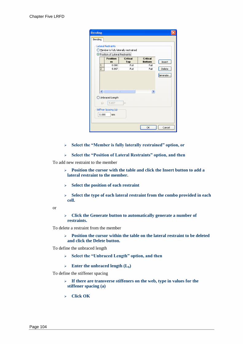
Chapter Five LRFD
Page 104
Select the “Member is fully laterally restrained” option, or
Select the “Position of Lateral Restraints” option, and then
To add new restraint to the member
Position the cursor with the table and click the Insert button to add a
lateral restraint to the member.
Select the position of each restraint
Select the type of each lateral restraint from the combo provided in each
cell.
or
Click the Generate button to automatically generate a number of
restraints.
To delete a restraint from the member
Position the cursor within the table on the lateral restraint to be deleted
and click the Delete button.
To define the unbraced length
Select the “Unbraced Length” option, and then
Enter the unbraced length (Lb)
To define the stiffener spacing
If there are transverse stiffeners on the web, type in values for the
stiffener spacing (a)
Click OK
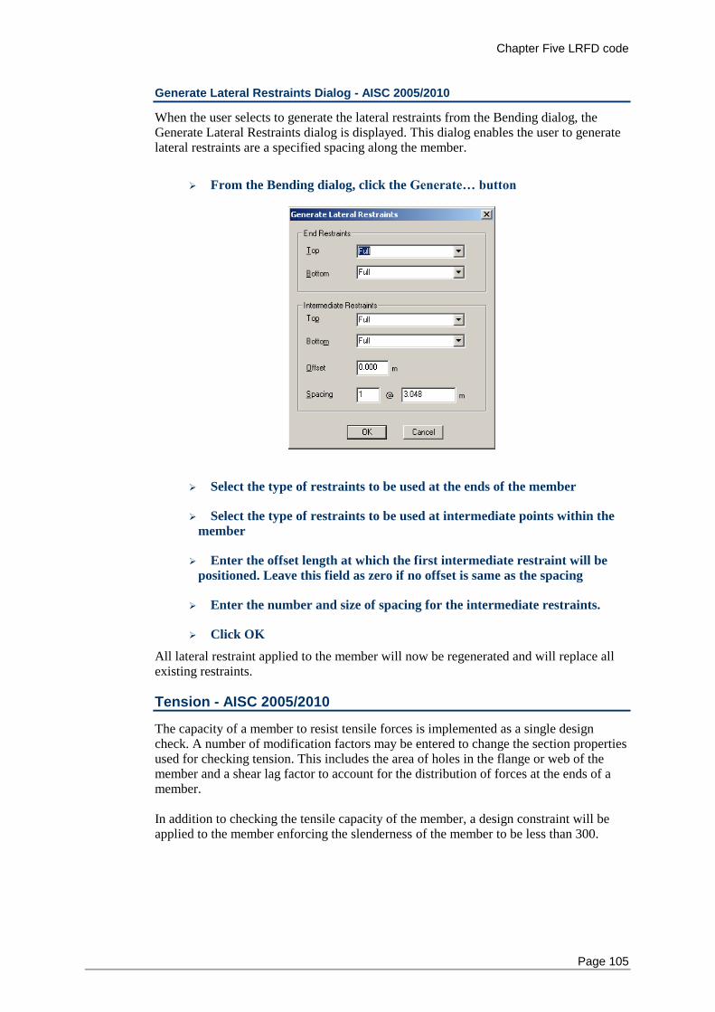
Chapter Five LRFD code
Page 105
Generate Lateral Restraints Dialog - AISC 2005/2010
When the user selects to generate the lateral restraints from the Bending dialog, the Generate Lateral Restraints dialog is displayed. This dialog enables the user to generate lateral restraints are a specified spacing along the member.
From the Bending dialog, click the Generate… button
Select the type of restraints to be used at the ends of the member
Select the type of restraints to be used at intermediate points within the
member
Enter the offset length at which the first intermediate restraint will be
positioned. Leave this field as zero if no offset is same as the spacing
Enter the number and size of spacing for the intermediate restraints.
Click OK
All lateral restraint applied to the member will now be regenerated and will replace all existing restraints.
Tension - AISC 2005/2010
The capacity of a member to resist tensile forces is implemented as a single design check. A number of modification factors may be entered to change the section properties used for checking tension. This includes the area of holes in the flange or web of the member and a shear lag factor to account for the distribution of forces at the ends of a member. In addition to checking the tensile capacity of the member, a design constraint will be applied to the member enforcing the slenderness of the member to be less than 300.
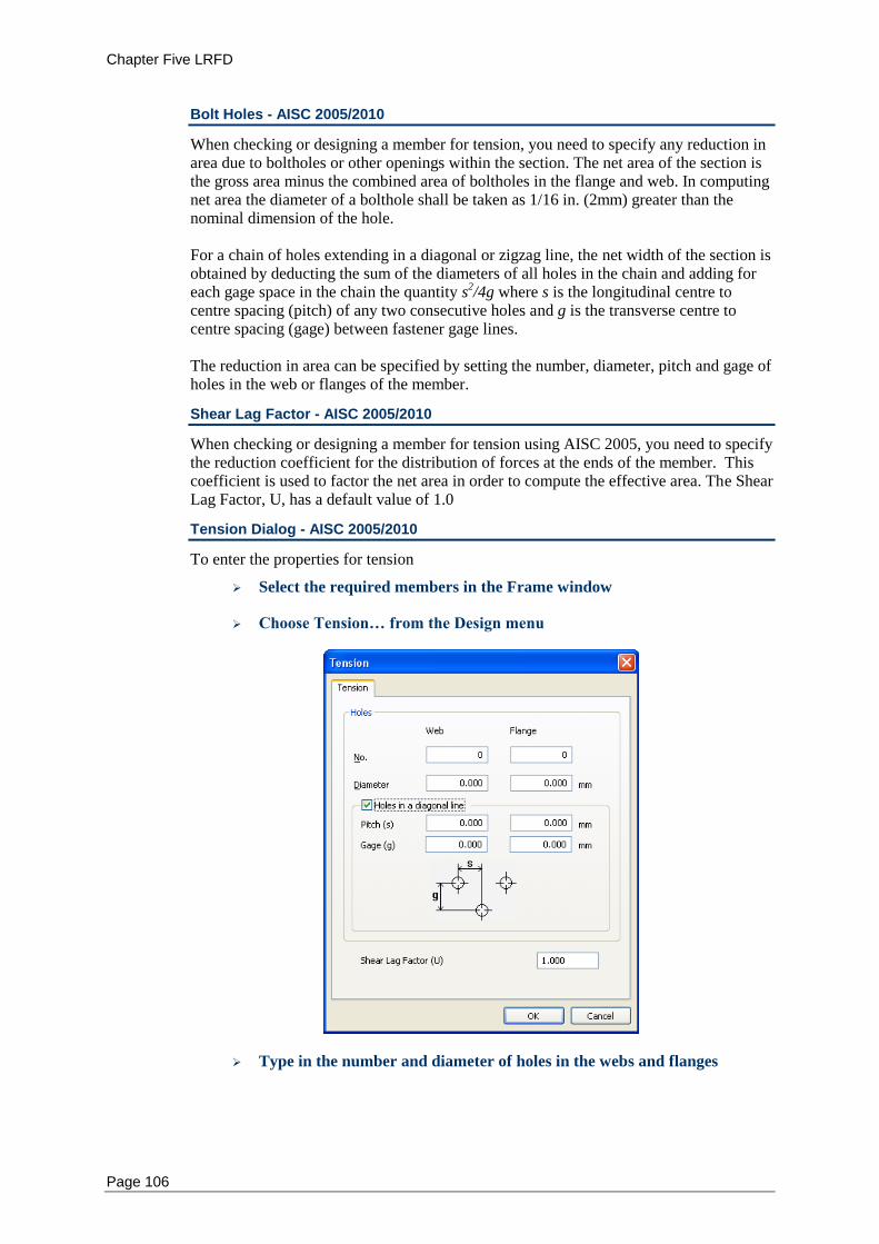
Chapter Five LRFD
Page 106
Bolt Holes - AISC 2005/2010
When checking or designing a member for tension, you need to specify any reduction in area due to boltholes or other openings within the section. The net area of the section is the gross area minus the combined area of boltholes in the flange and web. In computing net area the diameter of a bolthole shall be taken as 1/16 in. (2mm) greater than the nominal dimension of the hole. For a chain of holes extending in a diagonal or zigzag line, the net width of the section is obtained by deducting the sum of the diameters of all holes in the chain and adding for each gage space in the chain the quantity s
2/4g where s is the longitudinal centre to
centre spacing (pitch) of any two consecutive holes and g is the transverse centre to centre spacing (gage) between fastener gage lines. The reduction in area can be specified by setting the number, diameter, pitch and gage of holes in the web or flanges of the member.
Shear Lag Factor - AISC 2005/2010
When checking or designing a member for tension using AISC 2005, you need to specify the reduction coefficient for the distribution of forces at the ends of the member. This coefficient is used to factor the net area in order to compute the effective area. The Shear Lag Factor, U, has a default value of 1.0
Tension Dialog - AISC 2005/2010
To enter the properties for tension
Select the required members in the Frame window
Choose Tension… from the Design menu
Type in the number and diameter of holes in the webs and flanges
Chapter Five LRFD code
Page 107
If the holes extend in a diagonal or zigzag line check the Holes in
Diagonal Line box and enter the pitch and gage of holes in the webs and
flanges
Enter a value for the Shear Lag Factor (U)
Click OK
Compression - AISC 2005/2010
To determine the critical buckling load for a member, it is necessary to enter an effective length to indicate the type of restraint on the ends of the member. The effective length is given by an effective length factor multiplied by the length of the member. The effective length may be different for buckling in the major and minor axis directions. The effective lengths are given by
Lex = KxLcx, Ley = KyLcy and Lez = KzLcz
where Lcx and Lcy are the lengths of the member in x and y direction respectively, Kx and Ky are the two effective length factors for the major and minor axes respectively. Lcz and Kz are the effective length and effective length factors to resist torsional buckling. The initial values of Kx, Ky and Kz are 1.0.
Unbraced Length - AISC 2005/2010
To determine the critical buckling condition of a member, it is also necessary to know the spacing of any bracing (if any) along the member. This bracing could be provided by purlins, girts or other structural elements which are not modelled in Multiframe. Some bracing may only restrain lateral deflection in one direction, therefore it is necessary to enter unbraced lengths for both axes of the section, Lcx corresponding to the spacing of restraints preventing compression buckling about the x-x axis and Lcy corresponding to the spacing of restraints preventing compression buckling about the y-y axis. It is also possible to enter Lcz and Kz, used in the calculation of torsional buckling resistance, at this point.
Compression Dialog – AISC 2005/2010
To set the properties for compression
Select the required members in the Frame window
Choose Compression… from the Design menu
If the unbraced lengths of the member are to be specified directly then
Select the Unbrace Length radio button.
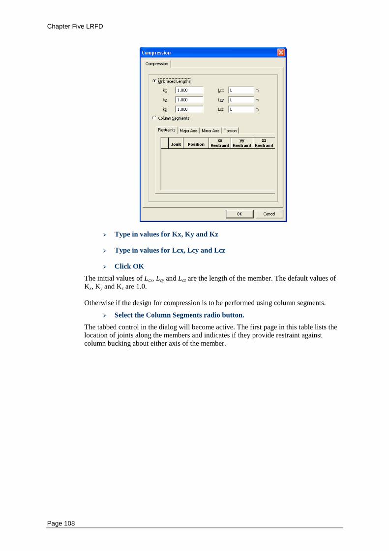
Chapter Five LRFD
Page 108
Type in values for Kx, Ky and Kz
Type in values for Lcx, Lcy and Lcz
Click OK
The initial values of Lcx, Lcy and Lcz are the length of the member. The default values of Kx, Ky and Kz are 1.0. Otherwise if the design for compression is to be performed using column segments.
Select the Column Segments radio button.
The tabbed control in the dialog will become active. The first page in this table lists the location of joints along the members and indicates if they provide restraint against column bucking about either axis of the member.
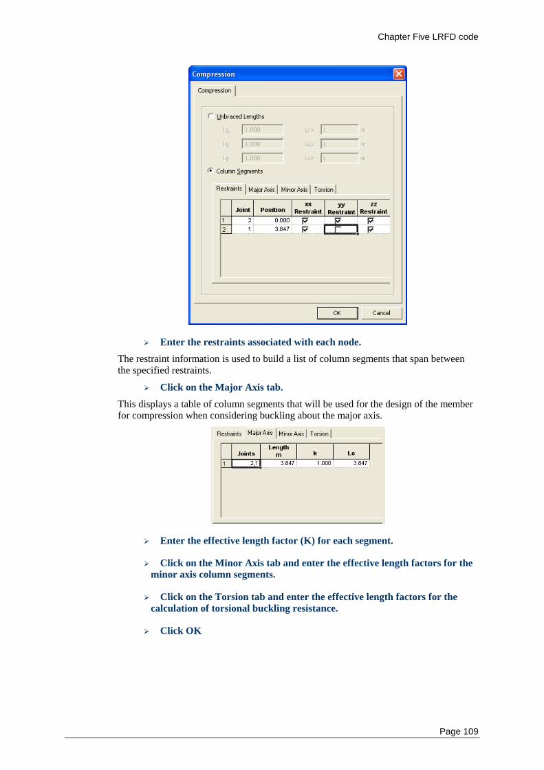
Chapter Five LRFD code
Page 109
Enter the restraints associated with each node.
The restraint information is used to build a list of column segments that span between the specified restraints.
Click on the Major Axis tab.
This displays a table of column segments that will be used for the design of the member for compression when considering buckling about the major axis.
Enter the effective length factor (K) for each segment.
Click on the Minor Axis tab and enter the effective length factors for the
minor axis column segments.
Click on the Torsion tab and enter the effective length factors for the
calculation of torsional buckling resistance.
Click OK
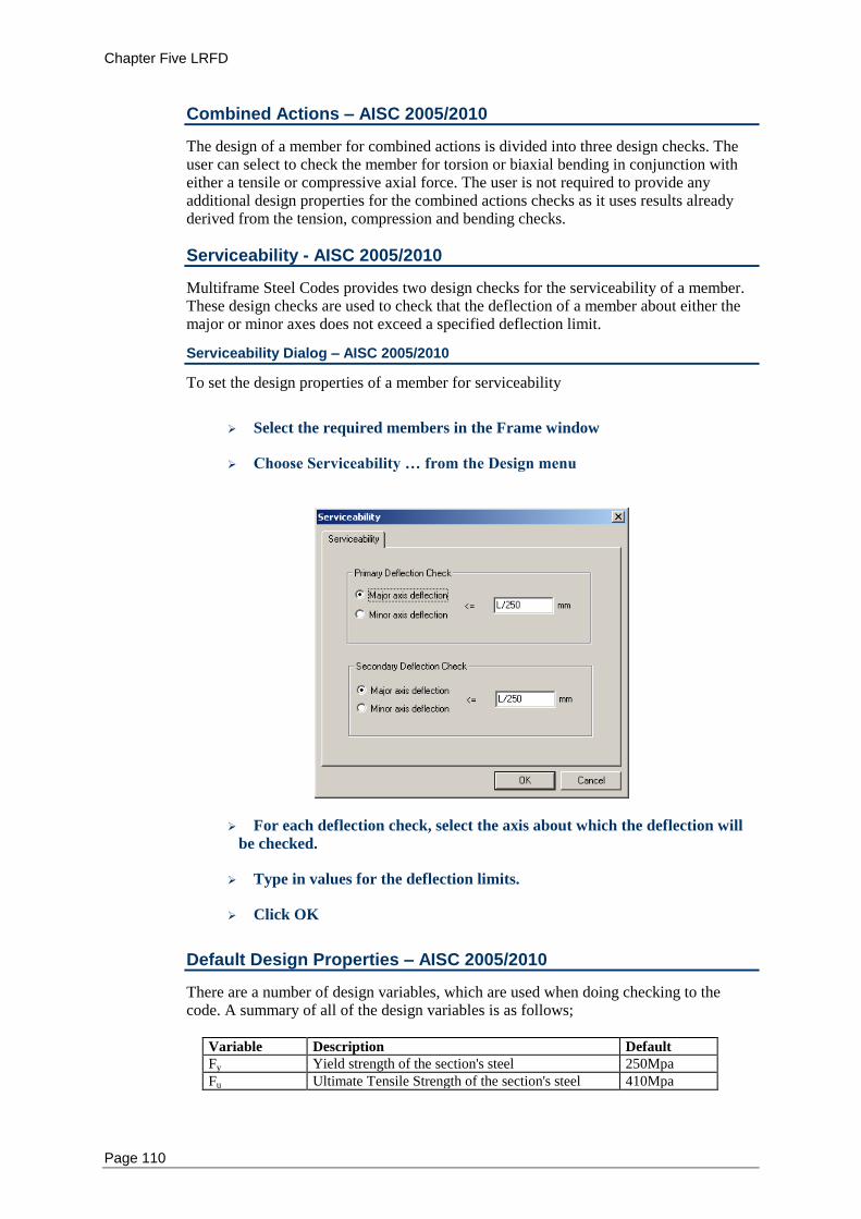
Chapter Five LRFD
Page 110
Combined Actions – AISC 2005/2010
The design of a member for combined actions is divided into three design checks. The user can select to check the member for torsion or biaxial bending in conjunction with either a tensile or compressive axial force. The user is not required to provide any additional design properties for the combined actions checks as it uses results already derived from the tension, compression and bending checks.
Serviceability - AISC 2005/2010
Multiframe Steel Codes provides two design checks for the serviceability of a member. These design checks are used to check that the deflection of a member about either the major or minor axes does not exceed a specified deflection limit.
Serviceability Dialog – AISC 2005/2010
To set the design properties of a member for serviceability
Select the required members in the Frame window
Choose Serviceability … from the Design menu
For each deflection check, select the axis about which the deflection will
be checked.
Type in values for the deflection limits.
Click OK
Default Design Properties – AISC 2005/2010
There are a number of design variables, which are used when doing checking to the code. A summary of all of the design variables is as follows;
Variable Description Default
Fy Yield strength of the section's steel 250Mpa
Fu Ultimate Tensile Strength of the section's steel 410Mpa
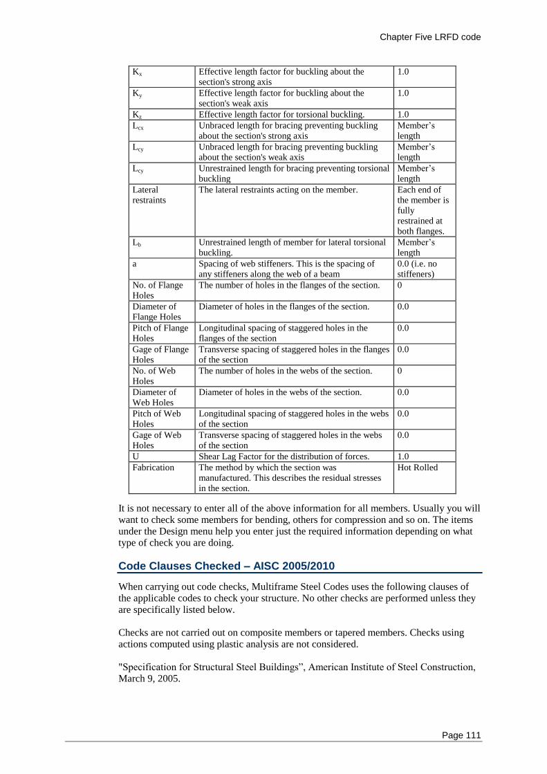
Chapter Five LRFD code
Page 111
Kx Effective length factor for buckling about the section's strong axis
1.0
Ky Effective length factor for buckling about the section's weak axis
1.0
Kz Effective length factor for torsional buckling. 1.0
Lcx Unbraced length for bracing preventing buckling about the section's strong axis
Member’s length
Lcy Unbraced length for bracing preventing buckling about the section's weak axis
Member’s length
Lcy Unrestrained length for bracing preventing torsional buckling
Member’s length
Lateral restraints
The lateral restraints acting on the member. Each end of the member is fully restrained at both flanges.
Lb Unrestrained length of member for lateral torsional buckling.
Member’s length
a Spacing of web stiffeners. This is the spacing of any stiffeners along the web of a beam
0.0 (i.e. no stiffeners)
No. of Flange Holes
The number of holes in the flanges of the section. 0
Diameter of Flange Holes
Diameter of holes in the flanges of the section. 0.0
Pitch of Flange Holes
Longitudinal spacing of staggered holes in the flanges of the section
0.0
Gage of Flange Holes
Transverse spacing of staggered holes in the flanges of the section
0.0
No. of Web Holes
The number of holes in the webs of the section. 0
Diameter of Web Holes
Diameter of holes in the webs of the section. 0.0
Pitch of Web Holes
Longitudinal spacing of staggered holes in the webs of the section
0.0
Gage of Web Holes
Transverse spacing of staggered holes in the webs of the section
0.0
U Shear Lag Factor for the distribution of forces. 1.0
Fabrication The method by which the section was manufactured. This describes the residual stresses in the section.
Hot Rolled
It is not necessary to enter all of the above information for all members. Usually you will want to check some members for bending, others for compression and so on. The items under the Design menu help you enter just the required information depending on what type of check you are doing.
Code Clauses Checked – AISC 2005/2010
When carrying out code checks, Multiframe Steel Codes uses the following clauses of the applicable codes to check your structure. No other checks are performed unless they are specifically listed below. Checks are not carried out on composite members or tapered members. Checks using actions computed using plastic analysis are not considered. "Specification for Structural Steel Buildings”, American Institute of Steel Construction, March 9, 2005.
Chapter Five LRFD
Page 112
The design checking procedure is as follows: The net area of the section is computed by subtracting the area of holes in the section. The effective area is then calculated as the net area (An) times the Shear Lag Factor (U). If the member is been checked for tension of compression, the slenderness of the section is checked. For angle members, the slenderness about either of the geometric axes is determined using the minimum radius of gyration of the section. For each serviceability load case: The maximum local displacement of the member is compared to the deflection limits specified deflection limits. For each load case representing a strength limit state, The design actions, or required strengths, of the member are determined as the maximum moment, shears and axial forces within the member. For first order analyses, the design bending moments are amplified using the moment amplification factors. Only moment amplification of braced frames is considered which corresponds to the situation in which no moments result from the lateral translation of the frame. Amplification factors for sway frames are not considered and a second order analysis should be used for sway frames requiring moment amplification. The plate elements of the section will be classified as Compact/Non-Compact/Slender as per the requirements of Clause B4 and Table B4-1. If the moments in the member are less than one ten thousandth of the yield moments the section is considered to be in pure compression and will be classified accordingly. If an element of the section is found to be slender, the stiffness reduction factors Q, Qa and Qs will be determined as set out in Clause E7. For Tension checks, the capacity of the member is determined in accordance with Chapter D. For Compression checks, the capacity of the member is firstly computed for the limit states of flexural buckling about the major and minor axis is accordance with clause E3. The capacity of the member for the limit state of flexural torsional-buckling is then computed using clauses E4. The compressive capacity of the member is regarded as being the minimum capacity determined for these three limit states. For Flexure checks the provisions of Chapter F are adhered to. Major and minor flexure checks are performed separately. The capacity of a member for the limit states of Yielding, Lateral-Torsional Buckling, Flange Local Buckling, Tension Flange Yielding, Flange Local Buckling and Web Local Buckling is computed. Not all limit states are applicable to every cross-section. These are detailed in Table F1.1. In addition flange local bucking will only be considered for sections with non-compact flanges. Similarly, web local buckling will only be considered for sections with non-compact webs. The design for Shear is carried out in accordance with Chapter G. Major and minor shear checks are performed separately. Specified stiffener spacings are accounted for.
Chapter Five LRFD code
Page 113
The combined cases of Torsion, Biaxial Bending and Axial loads are detailed in Chapter H. The resistance of a section to resistance torsional loading is calculated separately in accordance with Clause H3. Biaxial Bending and Axial loading capacity is a combination of the respective capacity checks carried out in previous chapters in accordance with Clause H1. For Doubly and Single Symmetric Members in Flexure and Tension the increase in the value of Cb varies between the LRFD and ASD versions of the code. This is detailed in Clause H1.2.

Chapter Nine User Code
Page 115
Chapter 10 Eurocode 3
This chapter describes the implementation of the EN 1-1-1993 “Specification for Structural Steel Buildings” within Multiframe Steel Codes. It provides a step-by-step description of how to modify the design properties used by the code.
Notation
Design Checks
Bending
Tension
Compression
Serviceability
National Annex
Default Design Properties
Code Clauses Checked
Notation – Eurocode 3
The notation used in Multiframe Steel Codes generally follows that used in the EC3 design code. Use has been made of subscripts to clarify the axis of the member to which a quantity refers. For example, the nominal flexural strengths about the Y and Z axes are denoted My,Rd and Mz,Rd respectively. The geometric axes of a member are denoted as the Y and Z axes where Y represented the horizontal axis of the member and Z the vertical axis of the member. For design to Eurocode 3, it is assumed that the Y axis is the major axis and Z is the minor axis.
Design Checks - Eurocode 3
The types of checks are grouped into the categories: Tension, Compression, Bending Torsion and Buckling. The user may specify which of these checks are performed when a member is designed or checked using Multiframe Steel Codes.
Bending - Eurocode 3
The design of a member for bending is divided into eight design checks. These check the flexural, shear and combined flexural-shear capacity of the member about the major and minor axes and the combined biaxial bending and axial force and the combined biaxial bending, shear and axial force. Each of these checks may consider one or more limit states depending upon the section and the actions within the member. When performing a bending check it is necessary to specify how lateral buckling of the member is resisted. Restraint could be provided by other members, purlins, girts or by other structural elements that are not modelled in Multiframe such as concrete slabs. Multiframe Steel Codes provides three methods of specifying how a member is restrained against lateral buckling. The user may specify that the member is fully restrained against lateral buckling in which case no lateral buckling checks will be performed.
Chapter Nine User Code
Page 116
The location and type of lateral restraints applied to the member in which case Multiframe Steel Codes will appropriately divide the member into a number of spans and consider the capacity of each of these spans in determining the capacity of the member. Alternatively the laterally unbraced length (Lb) can be specified. You may need to specify a number of properties relating to the location and type of lateral restraints and the stiffener spacing along the member
Lateral Restraints - Eurocode 3
If the spacing of lateral restraints along the member is specified, Multiframe Steel Codes uses this information to break the member up into a number of spans in order to determine lateral torsion buckling capacity of each span. In Multiframe Steel Codes, these spans are known as segments.
Each lateral restraint specified by the user is assumed to provide bracing against lateral displacement of the critical flange and/or prevent twist of the cross section. At any cross section, the critical flange is the flange that, in the absence of any restraint at that cross section, would deflect the furthest during buckling of the member. In most members the critical flange will be the compression flange. However for a cantilevered member, the critical flange is the tension flange. For each restraint located along a member, the user must specify the type of restraint. As this depends upon which flange is the critical flange, which is not know a priori, the user must specify the type of lateral restraint that would be present at a section if
The top flange was the critical flange, and
The bottom flange was the critical flange.
In Eurocode 3 no distinction is made between different types of lateral restraints. However, to be compatible with other design codes, Multiframe Steel Codes allows for lateral restraints at a cross section to be classified as follows
Full Restraint –supports the cross section against lateral displacement of the
critical flange and prevents twist of the cross section.
Partial Restraint – provides support against lateral displacement of the section at a
point other than the critical flange and prevents twist of the cross section.
Lateral Restraint – resists lateral displacement of the critical flange only.
For the purpose of design in Eurocode 3, each of these restraint types is consider adequate to provide lateral support to the cross section at which they are applied. Lateral restraints must always be specified at the ends of the beam and so the minimum number of lateral restraints is two. If no restraint exists at the end of a member then it should be specified as unrestrained in which case the member would be regarded as a cantilever. The initial lateral restraints applied to the member are full restraints at each end for either of the flanges being the critical flange.
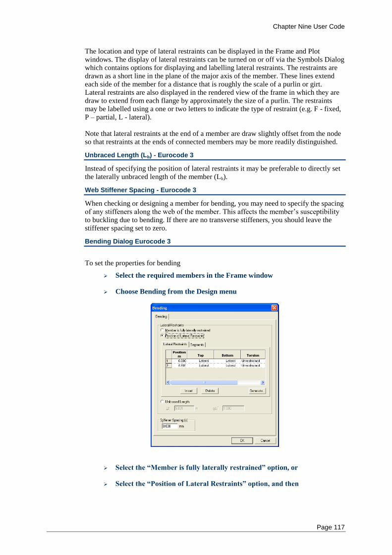
Chapter Nine User Code
Page 117
The location and type of lateral restraints can be displayed in the Frame and Plot windows. The display of lateral restraints can be turned on or off via the Symbols Dialog which contains options for displaying and labelling lateral restraints. The restraints are drawn as a short line in the plane of the major axis of the member. These lines extend each side of the member for a distance that is roughly the scale of a purlin or girt. Lateral restraints are also displayed in the rendered view of the frame in which they are draw to extend from each flange by approximately the size of a purlin. The restraints may be labelled using a one or two letters to indicate the type of restraint (e.g. F - fixed, P – partial, L - lateral). Note that lateral restraints at the end of a member are draw slightly offset from the node so that restraints at the ends of connected members may be more readily distinguished.
Unbraced Length (Lb) - Eurocode 3
Instead of specifying the position of lateral restraints it may be preferable to directly set the laterally unbraced length of the member (Lb).
Web Stiffener Spacing - Eurocode 3
When checking or designing a member for bending, you may need to specify the spacing of any stiffeners along the web of the member. This affects the member’s susceptibility to buckling due to bending. If there are no transverse stiffeners, you should leave the stiffener spacing set to zero.
Bending Dialog Eurocode 3
To set the properties for bending
Select the required members in the Frame window
Choose Bending from the Design menu
Select the “Member is fully laterally restrained” option, or
Select the “Position of Lateral Restraints” option, and then
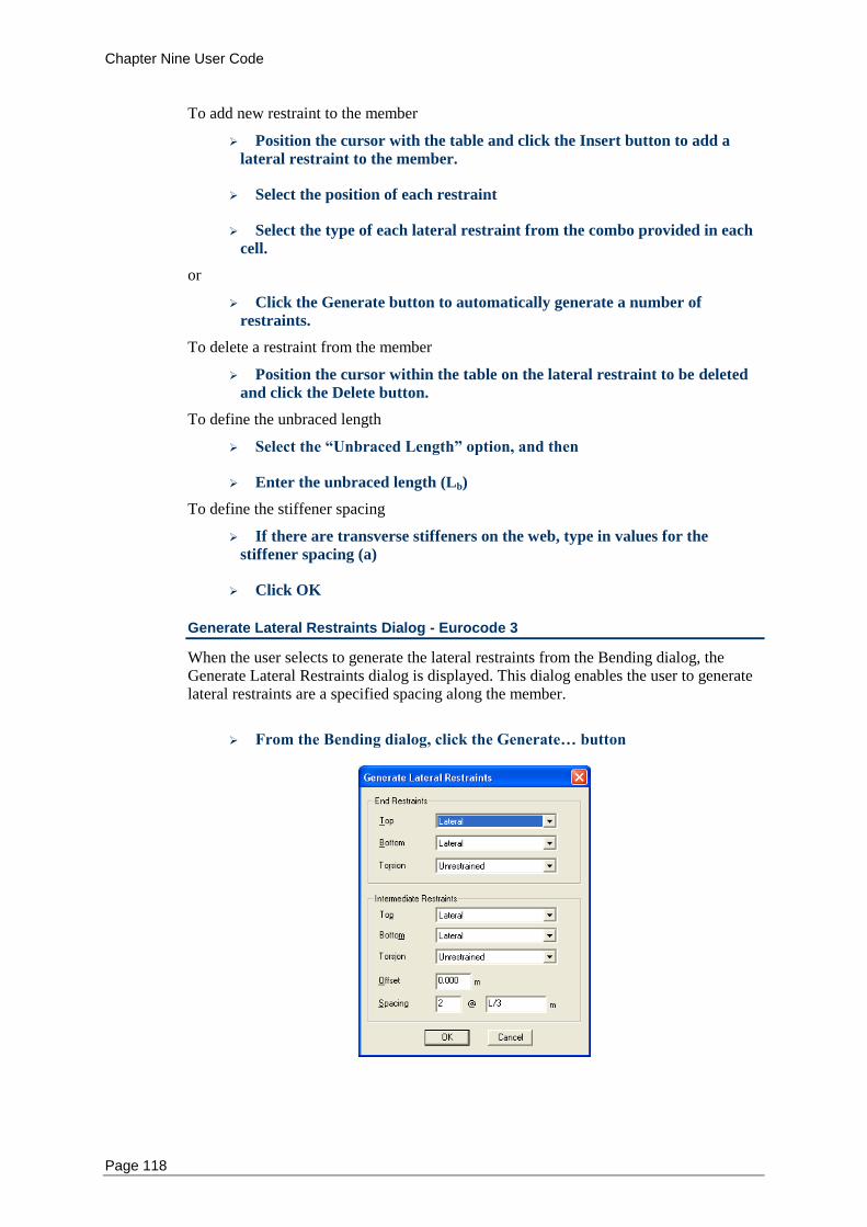
Chapter Nine User Code
Page 118
To add new restraint to the member
Position the cursor with the table and click the Insert button to add a
lateral restraint to the member.
Select the position of each restraint
Select the type of each lateral restraint from the combo provided in each
cell.
or
Click the Generate button to automatically generate a number of
restraints.
To delete a restraint from the member
Position the cursor within the table on the lateral restraint to be deleted
and click the Delete button.
To define the unbraced length
Select the “Unbraced Length” option, and then
Enter the unbraced length (Lb)
To define the stiffener spacing
If there are transverse stiffeners on the web, type in values for the
stiffener spacing (a)
Click OK
Generate Lateral Restraints Dialog - Eurocode 3
When the user selects to generate the lateral restraints from the Bending dialog, the Generate Lateral Restraints dialog is displayed. This dialog enables the user to generate lateral restraints are a specified spacing along the member.
From the Bending dialog, click the Generate… button
Chapter Nine User Code
Page 119
Select the type of restraints to be used at the ends of the member
Select the type of restraints to be used at intermediate points within the
member
Enter the offset length at which the first intermediate restraint will be
positioned. Leave this field as zero if no offset is same as the spacing
Enter the number and size of spacing for the intermediate restraints.
Click OK
All lateral restraint applied to the member will now be regenerated and will replace all existing restraints.
Tension - Eurocode 3
The capacity of a member to resist tensile forces is implemented as a single design check. A number of modification factors may be entered to change the section properties used for checking tension. This includes the area of holes in the flange or web of the member and a shear lag factor to account for the distribution of forces at the ends of a member. In addition to checking the tensile capacity of the member, a design constraint will be applied to the member enforcing the slenderness of the member to be less than 300.
Bolt Holes - Eurocode 3
When checking or designing a member for tension, you need to specify any reduction in area due to boltholes or other openings within the section. The net area of the section is the gross area minus the combined area of boltholes in the flange and web. For a chain of holes extending in a diagonal or zigzag line, the net width of the section is obtained by deducting the sum of the diameters of all holes in the chain and adding for each gage space in the chain the quantity s
2/4p where s is the longitudinal centre to
centre spacing of any two consecutive holes and p is the transverse centre to centre pitch between fastener gage lines. The reduction in area can be specified by setting the number, diameter, pitch and gage of holes in the web or flanges of the member.
Tension Dialog - Eurocode 3
To enter the properties for tension
Select the required members in the Frame window
Choose Tension… from the Design menu
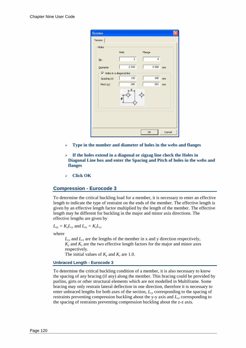
Chapter Nine User Code
Page 120
Type in the number and diameter of holes in the webs and flanges
If the holes extend in a diagonal or zigzag line check the Holes in
Diagonal Line box and enter the Spacing and Pitch of holes in the webs and
flanges
Click OK
Compression - Eurocode 3
To determine the critical buckling load for a member, it is necessary to enter an effective length to indicate the type of restraint on the ends of the member. The effective length is given by an effective length factor multiplied by the length of the member. The effective length may be different for buckling in the major and minor axis directions. The effective lengths are given by
Ley = KyLcy and Lez = KzLcz
where Lcy and Lcz are the lengths of the member in x and y direction respectively, Ky and Kz are the two effective length factors for the major and minor axes respectively. The initial values of Ky and Kz are 1.0.
Unbraced Length - Eurocode 3
To determine the critical buckling condition of a member, it is also necessary to know the spacing of any bracing (if any) along the member. This bracing could be provided by purlins, girts or other structural elements which are not modelled in Multiframe. Some bracing may only restrain lateral deflection in one direction, therefore it is necessary to enter unbraced lengths for both axes of the section, Lcy corresponding to the spacing of restraints preventing compression buckling about the y-y axis and Lcz corresponding to the spacing of restraints preventing compression buckling about the z-z axis.
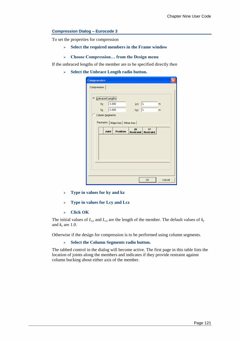
Chapter Nine User Code
Page 121
Compression Dialog – Eurocode 3
To set the properties for compression
Select the required members in the Frame window
Choose Compression… from the Design menu
If the unbraced lengths of the member are to be specified directly then
Select the Unbrace Length radio button.
Type in values for ky and kz
Type in values for Lcy and Lcz
Click OK
The initial values of Lcy and Lcz are the length of the member. The default values of ky and kz are 1.0. Otherwise if the design for compression is to be performed using column segments.
Select the Column Segments radio button.
The tabbed control in the dialog will become active. The first page in this table lists the location of joints along the members and indicates if they provide restraint against column bucking about either axis of the member.
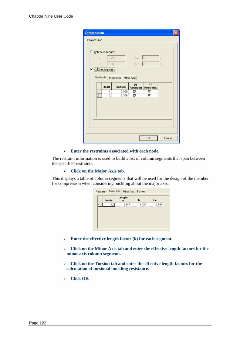
Chapter Nine User Code
Page 122
Enter the restraints associated with each node.
The restraint information is used to build a list of column segments that span between the specified restraints.
Click on the Major Axis tab.
This displays a table of column segments that will be used for the design of the member for compression when considering buckling about the major axis.
Enter the effective length factor (k) for each segment.
Click on the Minor Axis tab and enter the effective length factors for the
minor axis column segments.
Click on the Torsion tab and enter the effective length factors for the
calculation of torsional buckling resistance.
Click OK
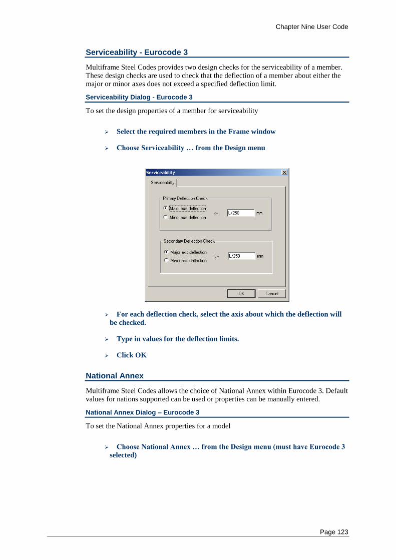
Chapter Nine User Code
Page 123
Serviceability - Eurocode 3
Multiframe Steel Codes provides two design checks for the serviceability of a member. These design checks are used to check that the deflection of a member about either the major or minor axes does not exceed a specified deflection limit.
Serviceability Dialog - Eurocode 3
To set the design properties of a member for serviceability
Select the required members in the Frame window
Choose Serviceability … from the Design menu
For each deflection check, select the axis about which the deflection will
be checked.
Type in values for the deflection limits.
Click OK
National Annex
Multiframe Steel Codes allows the choice of National Annex within Eurocode 3. Default values for nations supported can be used or properties can be manually entered.
National Annex Dialog – Eurocode 3
To set the National Annex properties for a model
Choose National Annex … from the Design menu (must have Eurocode 3
selected)
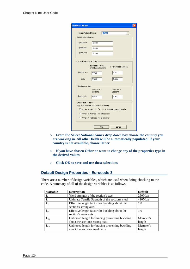
Chapter Nine User Code
Page 124
From the Select National Annex drop down box choose the country you
are working in. All other fields will be automatically populated. If your
country is not available, choose Other
If you have chosen Other or want to change any of the properties type in
the desired values
Click OK to save and use these selections
Default Design Properties - Eurocode 3
There are a number of design variables, which are used when doing checking to the code. A summary of all of the design variables is as follows;
Variable Description Default
fy Yield strength of the section's steel 250Mpa
fu Ultimate Tensile Strength of the section's steel 410Mpa
ky Effective length factor for buckling about the section's strong axis
1.0
ky Effective length factor for buckling about the section's weak axis
1.0
Lcy Unbraced length for bracing preventing buckling about the section's strong axis
Member’s length
Lcz Unbraced length for bracing preventing buckling about the section's weak axis
Member’s length
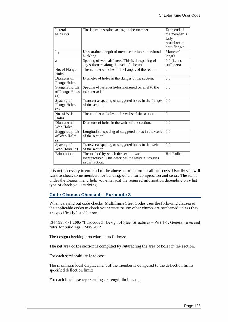
Chapter Nine User Code
Page 125
Lateral restraints
The lateral restraints acting on the member. Each end of the member is fully restrained at both flanges.
Lb Unrestrained length of member for lateral torsional buckling.
Member’s length
a Spacing of web stiffeners. This is the spacing of any stiffeners along the web of a beam
0.0 (i.e. no stiffeners)
No. of Flange Holes
The number of holes in the flanges of the section. 0
Diameter of Flange Holes
Diameter of holes in the flanges of the section. 0.0
Staggered pitch of Flange Holes (s)
Spacing of fastener holes measured parallel to the member axis
0.0
Spacing of Flange Holes (p)
Transverse spacing of staggered holes in the flanges of the section
0.0
No. of Web Holes
The number of holes in the webs of the section. 0
Diameter of Web Holes
Diameter of holes in the webs of the section. 0.0
Staggered pitch of Web Holes (s)
Longitudinal spacing of staggered holes in the webs of the section
0.0
Spacing of Web Holes (p)
Transverse spacing of staggered holes in the webs of the section
0.0
Fabrication The method by which the section was manufactured. This describes the residual stresses in the section.
Hot Rolled
It is not necessary to enter all of the above information for all members. Usually you will want to check some members for bending, others for compression and so on. The items under the Design menu help you enter just the required information depending on what type of check you are doing.
Code Clauses Checked – Eurocode 3
When carrying out code checks, Multiframe Steel Codes uses the following clauses of the applicable codes to check your structure. No other checks are performed unless they are specifically listed below. EN 1993-1-1:2005 “Eurocode 3: Design of Steel Structures – Part 1-1: General rules and rules for buildings”, May 2005 The design checking procedure is as follows: The net area of the section is computed by subtracting the area of holes in the section. For each serviceability load case: The maximum local displacement of the member is compared to the deflection limits specified deflection limits. For each load case representing a strength limit state,
Chapter Nine User Code
Page 126
The design actions, or required strengths, of the member are determined as the maximum moment, shears and axial forces within the member. For first order analyses, the design bending moments are amplified using the moment amplification factors. Only moment amplification of braced frames is considered which corresponds to the situation in which no moments result from the lateral translation of the frame. Amplification factors for sway frames are not considered and a second order analysis should be used for sway frames requiring moment amplification. The plate elements of the section will be classified as Class 1, 2, 3 or 4 as per the requirements of Section 5.5.2 and Table 5.2. In Class 4 cross sections effective widths are calculated to make the necessary allowances reductions in resistance to the effects of local buckling. For Tension checks, the capacity of the member is determined in accordance with Chapter 6.2.3. The smaller of the values for design plastic resistance without considering fastener holes and the ultimate resistance including fastener holes is used. For Compression checks, the capacity of the member is firstly computed using the area of the cross section for Class 1, 2 or 3 cross-sections. For Class 4 cross-sections the effective area is used. For Bending checks the provisions of Chapter 6.2.5is adhered to. Major and minor flexure checks are performed separately. For Class 1 and 2 cross-sections are designed to their elastic limit. Class 3 and 3 cross-sections to their plastic limit, with Class 4 cross-sections using a reduced effective Plastic Modulus. At present no allowance is made for fastener holes. The design for Shear is carried out in accordance with Chapter 6.2.6. Major and minor shear checks are performed separately. Where shear force is present is allowed for in the combined Bending and Shear check as described in Chapter 6.2.8. The combined cases of Bending and Axial force and Bending, Shear and Axial force are checked as described in Chapter 6.2.9. The Shear check is only included if present. Torsion is detailed in Chapter 6.2.7. The torsional strength is a combination of the uniform torsional section resistance and the biomoment section resistance as per “The Behaviour and Design of Steel Structures to EC3” by Trahair et al. The buckling cases of Compression Buckling, Lateral Torsional Buckling and Bending and Compression buckling are checked in accordance with Chapter 6.3. The Bending and Compression buckling interaction factors are calculated by either Method 1, detailed in EN 1993-1-1 Annex A or Method 2, detailed in EN 1993-1-1 Annex B. The decision as to which method to use depends on which National Annex is used or can be manually selected.
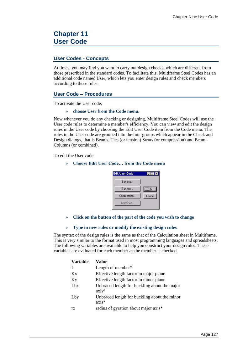
Chapter Nine User Code
Page 127
Chapter 11 User Code
User Codes - Concepts
At times, you may find you want to carry out design checks, which are different from those prescribed in the standard codes. To facilitate this, Multiframe Steel Codes has an additional code named User, which lets you enter design rules and check members according to these rules.
User Code – Procedures
To activate the User code,
choose User from the Code menu.
Now whenever you do any checking or designing, Multiframe Steel Codes will use the User code rules to determine a member's efficiency. You can view and edit the design rules in the User code by choosing the Edit User Code item from the Code menu. The rules in the User code are grouped into the four groups which appear in the Check and Design dialogs, that is Beams, Ties (or tension) Struts (or compression) and Beam-Columns (or combined). To edit the User code
Choose Edit User Code… from the Code menu
Click on the button of the part of the code you wish to change
Type in new rules or modify the existing design rules
The syntax of the design rules is the same as that of the Calculation sheet in Multiframe. This is very similar to the format used in most programming languages and spreadsheets. The following variables are available to help you construct your design rules. These variables are evaluated for each member as the member is checked.
Variable Value
L Length of member*
Kx Effective length factor in major plane
Ky Effective length factor in minor plane
Lbx Unbraced length for buckling about the major axis*
Lby Unbraced length for buckling about the minor axis*
rx radius of gyration about major axis*
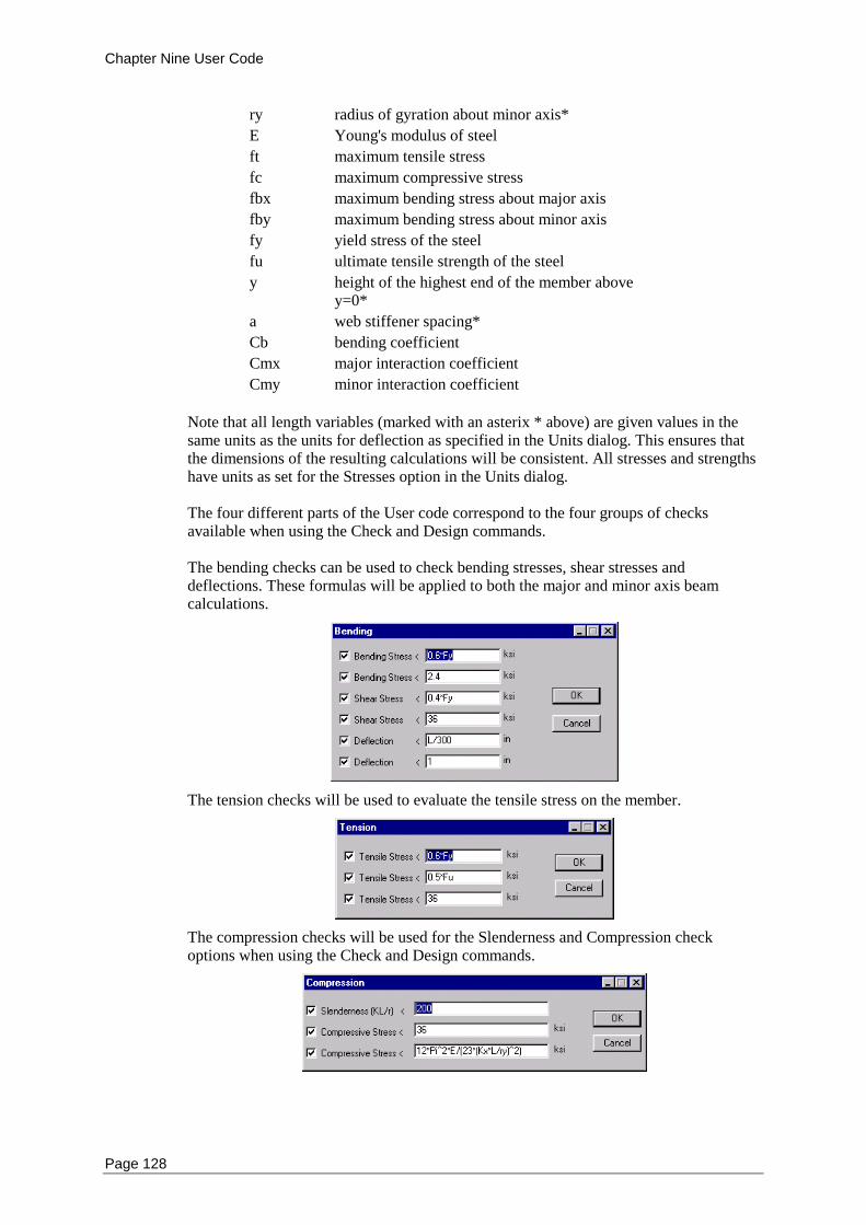
Chapter Nine User Code
Page 128
ry radius of gyration about minor axis*
E Young's modulus of steel
ft maximum tensile stress
fc maximum compressive stress
fbx maximum bending stress about major axis
fby maximum bending stress about minor axis
fy yield stress of the steel
fu ultimate tensile strength of the steel
y height of the highest end of the member above y=0*
a web stiffener spacing*
Cb bending coefficient
Cmx major interaction coefficient
Cmy minor interaction coefficient
Note that all length variables (marked with an asterix * above) are given values in the same units as the units for deflection as specified in the Units dialog. This ensures that the dimensions of the resulting calculations will be consistent. All stresses and strengths have units as set for the Stresses option in the Units dialog. The four different parts of the User code correspond to the four groups of checks available when using the Check and Design commands. The bending checks can be used to check bending stresses, shear stresses and deflections. These formulas will be applied to both the major and minor axis beam calculations.
The tension checks will be used to evaluate the tensile stress on the member.
The compression checks will be used for the Slenderness and Compression check options when using the Check and Design commands.
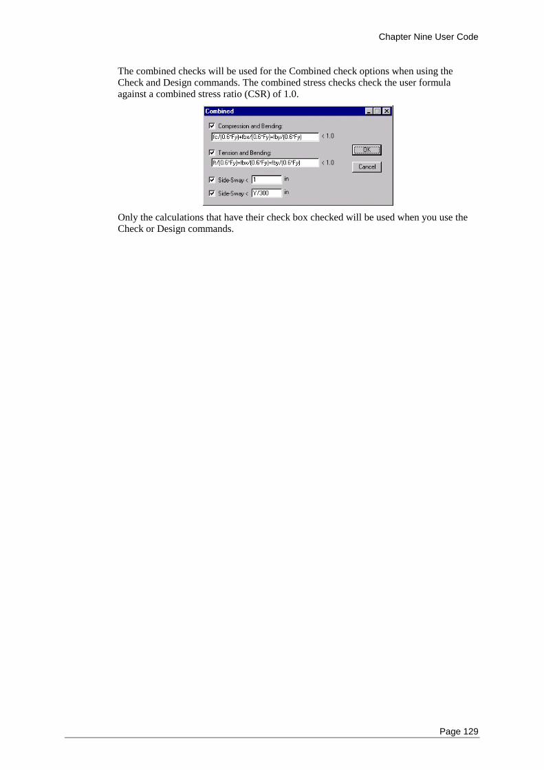
Chapter Nine User Code
Page 129
The combined checks will be used for the Combined check options when using the Check and Design commands. The combined stress checks check the user formula against a combined stress ratio (CSR) of 1.0.
Only the calculations that have their check box checked will be used when you use the Check or Design commands.

Chapter Ten Steel Designer Reference
Page 131
Chapter 12 Multiframe Steel Codes Reference
This chapter summarises the extended functionality of windows and the extra menu commands that are available in Multiframe when Multiframe Steel Codes is enabled.
Windows
Menus
Windows
Multiframe Steel Codes operates within the standard Multiframe windows and adds a Report window. The following windows are available:
Frame Window
Data Window
Load Window
Result Window
Plot Window
Report Window
Frame Window
This window is used for specifying the sections and design properties of the members in a frame.
Data Window
This window is used for viewing the data describing the geometry and loading of the frame and for displaying and editing the design properties of the structure.
Load Window
This window is used for viewing the loading applied to the frame. One load case at a time may be viewed in this window. You can choose which load case is displayed by choosing the appropriate item from the bottom of the Case menu.
Result Window
This window is used for viewing the results of the analysis and design calculations carried out on the frame. The results for one load case at a time may be viewed in this window. You can choose which load case is displayed by choosing the appropriate item from the bottom of the Case menu. You can also view the Design Efficiency table in this window.
Plot Window
This window is used for viewing diagrams of the results of the analysis carried out on the frame. The results for one load case at a time may be viewed in this window. You can choose which load case is displayed by choosing the appropriate item from the bottom of the Case menu. You can also view a colour plot of design efficiency in this window.
Chapter Ten Steel Designer Reference
Page 132
Report Window
This window is used for viewing a summary report of the design checks carried out on the frame. You can turn on or off the option to create a summary report when you use the Check or Design commands.
Menus
When the Multiframe Steel Codes module is active some extra menu items are displayed in the Multiframe menus. In addition, the function of some of the Multiframe menu items change in order to support the Report Window: The menu items with modified behaviour and the additional menu items are as follows:
Group Menu
Design Menu
Code Submenu
Display Menu
Efficiency Submenu
Help Menu
Group Menu
The Group menu provides commands for organising the members in the structural model into groups or assemblies. The entries in this menu relevant to design are list below.
Create Design Member
Group the selected members together to form a multi-member design member.
Remove Design Member
Delete or split the selected members from multi-member design member(s).
Design Menu
The Design menu provides commands for checking and optimising the members in your structure.
Code
See “Code Submenu”
Check
Check the selected members in the Frame window for their compliance with the current code. You may use the Check dialog to choose which design calculations should be carried out and which load cases should be checked.
Design
Select the lightest weight sections for the selected members in the Frame window that will satisfy the design criteria. You may use the Design dialog to choose which design calculations should be carried out and which load cases should be examined.
Chapter Ten Steel Designer Reference
Page 133
Bending
Specify the design parameters controlling bending checks. Enter the unbraced lengths for the selected members in the Frame window and specify any web stiffener spacing.
Tension
Specify the design parameters used for tension checks. Specify the area of any boltholes, which must be subtracted from the cross-sectional area of the section when doing design calculations.
Compression
Specify the design parameters controlling compression checks. Allows you to select the effective lengths and the unbraced lengths for the selected members in the Frame window.
Combined
Specify the design parameters controlling combined bending and compression checks.
Serviceability
The Serviceability command allows you to set design information regarding serviceability of the frame this is currently only used for the AS4100 and NZS3404 design codes.
Seismic
Specify the design parameters controlling seismic design checks. This is currently only used for the NZS3404 design code to specify the category of a member.
Design Details
This command allows you to set all of the design information for the members selected in the Frame window. As a short cut, you can double click on a member to bring up this design dialog for that member.
Steel Grade
Specify the grade of steel for the selected members in the Frame window. You can choose from a list of standard grades or enter custom values for the yield and ultimate tensile strength.
Constraints
Specify whether there are any constraints on the size of section, which may be chosen for the selected members. You can also specify if you require all of the selected members to be of the same section type.
Frame Type
Specify whether the current frame is able to sway or is braced against horizontal movement.
Chapter Ten Steel Designer Reference
Page 134
Allowable Stresses
This command allows you to specify the allowable stress increase for each load case on the structure. The allowable increase is entered as a factor (usually 1.33 or 1.5).
Capacity Factors
The Capacity Factors command allows you to modify the capacity factors for the frame. This is only used with limit state design codes.
Use Best Sections
Automatically replace the section type of each member with its lightest weight section as chosen using the design command.
Code Submenu
The code menu allows you to select the design code you wish to use for checking. The current code is indicated with a check mark beside the item. This determines which code is used when you do design calculations.
AS1250
Not currently implemented
AS 4100
Australian steel design code.
AS 4600
Australian/New Zealand steel design code.
NZS 3404
New Zealand steel design code
BS5 950
British steel design code.
CISC
Not currently implemented
Eurocode
Eurocode 3 steel design code.
AIJ
Current Japanese steel design code.
ASD
American ASD steel design code.
Chapter Ten Steel Designer Reference
Page 135
LRFD
American LRFD steel design code
User
Allows the user to set their own design criteria and checks.
Edit User Code
This command lets you edit the design calculations that will be used when you choose to check or design a frame using the User code. You can choose which checks should be performed and what calculations should be used for each check. You can type in your own equations
Display Menu
The Display menu lets you control what s displayed in each of the windows.
Data / Design Details
Display a table in the Data window of the design information for each of the members in the frame. The table includes steel grade, effective and unbraced lengths and limits on the size of the section for the member
Results / Member Efficiency
Display a table in the Results window of the computed efficiency for each of the members in the frame. The efficiency is the ratio of the design action or stress to the design strengths according to the current design code expressed as a percentage.
Efficiency
See “Efficiency Submenu”
Efficiency Submenu
The items in this menu may be used to control which type of efficiency diagram is displayed in the Plot window. The items listed in this menu change according to the current design code.
AS 4100 and NZS3404
The following items are available in the Efficiency submenu when using the Australian / International version of Multiframe Steel Codes.
Overall
Display the Overall efficiency as a colour on each member for the current load case in the Plot window.
Chapter Ten Steel Designer Reference
Page 136
Bending (Major Section)
Display the Major Bending/Major Section Bending efficiency as a colour on each member for the current load case in the Plot window.
Bending (Major Member)
Display the Major Member Bending efficiency as a colour on each member for the current load case in the Plot window.
Bending (Major Shear)
Display the Major Shear efficiency as a colour on each member for the current load case in the Plot window.
Bending (Minor Section)
Display the Minor Bending/ Minor Section Bending efficiency as a colour on each member for the current load case in the Plot window.
Bending (Minor Shear)
Display the Minor Shear/Bending (Minor Shear) efficiency as a colour on each member for the current load case in the Plot window.
Tension
Display the Tension efficiency as a colour on each member for the current load case in the Plot window.
Compression (Section)
Display the Compression/Section Compression efficiency as a colour on each member for the current load case in the Plot window.
Compression (Major Member)
Display the Major Member Compression efficiency as a colour on each member for the current load case in the Plot window.
Compression (Minor Member)
Display the Minor Member Compression efficiency as a colour on each member for the current load case in the Plot window.
Combined (Major Section)
Display the Combined (Major Section) efficiency as a colour on each member for the current load case in the Plot window.
Combined (Minor Section)
Display the Combined (Minor Section) efficiency as a colour on each member for the current load case in the Plot window.
Chapter Ten Steel Designer Reference
Page 137
Combined (Major In-Plane)
Display the Combined (Major In-Plane) efficiency as a colour on each member for the current load case in the Plot window.
Combined (Minor In-Plane)
Display the Combined (Minor In-Plane) efficiency as a colour on each member for the current load case in the Plot window.
Combined (Out-of-plane)
Display the Combined (Out-of-plane) efficiency as a colour on each member for the current load case in the Plot window.
Combined (Biaxial Section)
Display the Combined (Biaxial Section) efficiency as a colour on each member for the current load case in the Plot window.
Combined (Biaxial Member)
Display the Combined (Biaxial Member) efficiency as a colour on each member for the current load case in the Plot window.
Primary Deflection
Display the Primary Deflection efficiency as a colour on each member for the current load case in the Plot window.
Secondary Deflection
Display the Secondary Deflection efficiency as a colour on each member for the current load case in the Plot window.
ASD / AIJ
The following items are available in the Efficiency submenu when using USA and Japan versions of Multiframe Steel Codes.
Overall
Display the Overall efficiency as a colour on each member for the current load case in the Plot window.
Major Bending
Display the Major Bending/Major Section Bending efficiency as a colour on each member for the current load case in the Plot window.
Minor Shear
Display the Minor Shear/Bending (Minor Shear) efficiency as a colour on each member for the current load case in the Plot window.
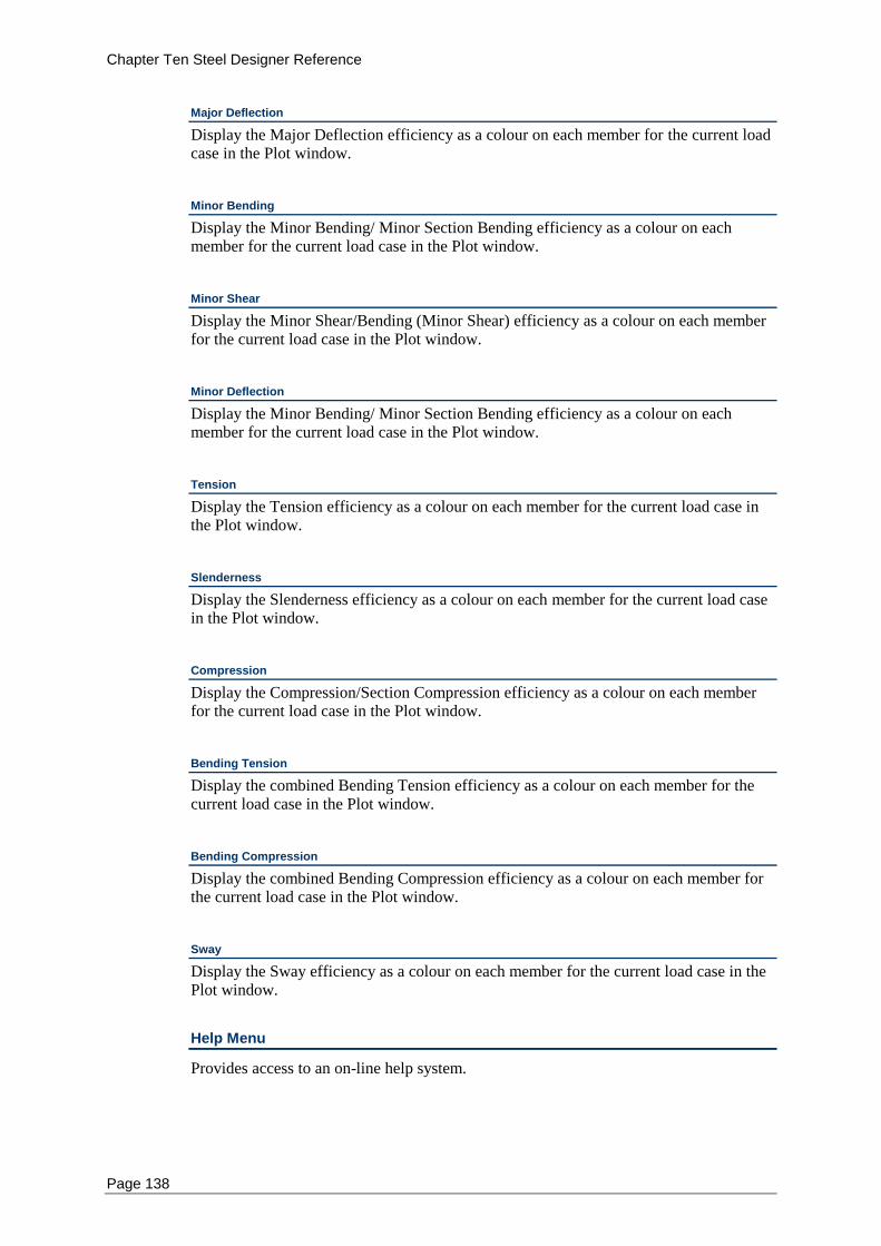
Chapter Ten Steel Designer Reference
Page 138
Major Deflection
Display the Major Deflection efficiency as a colour on each member for the current load case in the Plot window.
Minor Bending
Display the Minor Bending/ Minor Section Bending efficiency as a colour on each member for the current load case in the Plot window.
Minor Shear
Display the Minor Shear/Bending (Minor Shear) efficiency as a colour on each member for the current load case in the Plot window.
Minor Deflection
Display the Minor Bending/ Minor Section Bending efficiency as a colour on each member for the current load case in the Plot window.
Tension
Display the Tension efficiency as a colour on each member for the current load case in the Plot window.
Slenderness
Display the Slenderness efficiency as a colour on each member for the current load case in the Plot window.
Compression
Display the Compression/Section Compression efficiency as a colour on each member for the current load case in the Plot window.
Bending Tension
Display the combined Bending Tension efficiency as a colour on each member for the current load case in the Plot window.
Bending Compression
Display the combined Bending Compression efficiency as a colour on each member for the current load case in the Plot window.
Sway
Display the Sway efficiency as a colour on each member for the current load case in the Plot window.
Help Menu
Provides access to an on-line help system.
Chapter Ten Steel Designer Reference
Page 139
Multiframe Steel Codes Help
This command allows you to launch the table of contents of the Multiframe Steel Codes help file.
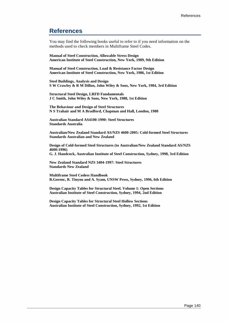
References
Page 140
References
You may find the following books useful to refer to if you need information on the methods used to check members in Multiframe Steel Codes. Manual of Steel Construction, Allowable Stress Design
American Institute of Steel Construction, New York, 1989, 9th Edition
Manual of Steel Construction, Load & Resistance Factor Design
American Institute of Steel Construction, New York, 1986, 1st Edition
Steel Buildings, Analysis and Design
S W Crawley & R M Dillon, John Wiley & Sons, New York, 1984, 3rd Edition
Structural Steel Design, LRFD Fundamentals
J C Smith, John Wiley & Sons, New York, 1988, 1st Edition
The Behaviour and Design of Steel Structures
N S Trahair and M A Bradford, Chapman and Hall, London, 1988
Australian Standard AS4100-1990: Steel Structures
Standards Australia
Australian/New Zealand Standard AS/NZS 4600-2005: Cold-formed Steel Structures
Standards Australian and New Zealand
Design of Cold-formed Steel Structures (to Australian/New Zealand Standard AS/NZS
4600:1996)
G. J. Handcock, Australian Institute of Steel Construction, Sydney, 1998, 3rd Edition
New Zealand Standard NZS 3404-1997: Steel Structures
Standards New Zealand
Multiframe Steel Codess Handbook
B.Gorenc, R. Tinyou and A. Syam, UNSW Press, Sydney, 1996, 6th Edition
Design Capacity Tables for Structural Steel. Volume 1: Open Sections
Australian Institute of Steel Construction, Sydney, 1994, 2nd Edition
Design Capacity Tables for Structural Steel Hollow Sections
Australian Institute of Steel Construction, Sydney, 1992, 1st Edition
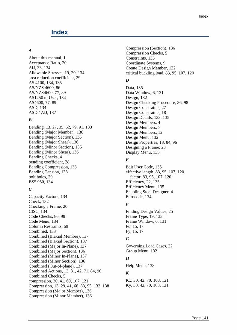
Index
Page 141
Index
A
About this manual, 1 Acceptance Ratio, 20 AIJ, 33, 134 Allowable Stresses, 19, 20, 134 area reduction coefficient, 29 AS 4100, 134, 135 AS/NZS 4600, 86 AS/NZS4600, 77, 89 AS1250 to User, 134 AS4600, 77, 89 ASD, 134 ASD / AIJ, 137
B
Bending, 13, 27, 35, 62, 79, 91, 133 Bending (Major Member), 136 Bending (Major Section), 136 Bending (Major Shear), 136 Bending (Minor Section), 136 Bending (Minor Shear), 136 Bending Checks, 4 bending coefficient, 28 Bending Compression, 138 Bending Tension, 138 bolt holes, 29 BS5 950, 134
C
Capacity Factors, 134 Check, 132 Checking a Frame, 20 CISC, 134 Code Checks, 86, 98 Code Menu, 134 Column Restraints, 69 Combined, 133 Combined (Biaxial Member), 137 Combined (Biaxial Section), 137 Combined (Major In-Plane), 137 Combined (Major Section), 136 Combined (Minor In-Plane), 137 Combined (Minor Section), 136 Combined (Out-of-plane), 137 Combined Actions, 13, 31, 42, 71, 84, 96 Combined Checks, 5 compression, 30, 41, 69, 107, 121 Compression, 13, 29, 41, 68, 83, 95, 133, 138 Compression (Major Member), 136 Compression (Minor Member), 136
Compression (Section), 136 Compression Checks, 5 Constraints, 133 Coordinate Systems, 9 Create Design Member, 132 critical buckling load, 83, 95, 107, 120
D
Data, 135 Data Window, 6, 131 Design, 132 Design Checking Procedure, 86, 98 Design Constraints, 27 Design Constraints, 18 Design Details, 133, 135 Design Members, 4 Design Members, 7 Design Members, 12 Design Menu, 132 Design Properties, 13, 84, 96 Designing a Frame, 23 Display Menu, 135
E
Edit User Code, 135 effective length, 83, 95, 107, 120
factor, 83, 95, 107, 120 Efficiency, 22, 135 Efficiency Menu, 135 Enabling Steel Designer, 4 Eurocode, 134
F
Finding Design Values, 25 Frame Type, 19, 133 Frame Window, 6, 131 Fu, 15, 17 Fy, 15, 17
G
Governing Load Cases, 22 Group Menu, 132
H
Help Menu, 138
K
Kx, 30, 42, 70, 108, 121 Ky, 30, 42, 70, 108, 121
Index
Page 142
L
Lbx, 27 Lby, 27 Lcx, 41 Load Window, 131 LRFD, 135
M
Major Bending, 137 Major Deflection, 138 Member Efficiency, 135 Menus, 132 Minor Bending, 138 Minor Deflection, 138 Minor Shear, 137, 138
N
NZS 3404, 134
O
Optimization, 25 Optimum Sections, 24 Overall, 135, 137
P
Plot Window, 6, 131 Primary Deflection, 137 Printing, 25
R
Remove Design Member, 132 Report Window, 7, 132 restraint, 83, 95, 107, 120 Result Window, 6, 131 Results, 135
S
Saving the report, 26 Saving your Work, 26 Secondary Deflection, 137 Section Constraints, 18 Section Type, 15 Seismic, 133 Seismic, 35, 43 Seismic Checks, 5 Serviceability, 42, 72, 133 Serviceability Checks, 5 Set Best Section, 25 Setting Properties, 12, 31, 44, 72, 77, 89 Shear Area, 10 Slenderness, 138 Starting Steel Designer, 4 Steel Designer Help, 139 Steel Grade, 15, 85, 97, 133 Sway, 138
T
Tension, 13, 28, 39, 66, 82, 94, 133, 136, 138 Tension Checks, 4
U
ultimate tensile strength, 15 Unbraced Length, 27, 30, 41, 83, 95 Unbraced Lengths, 69 Use Best Sections, 24, 134 User, 135
Y
yield strength, 15