Embed Size (px)
Citation preview
multiFiltrate
Technical Manual
Edition: 6/03.07
Part no. M28 003 1
Service Manual

Fresenius Medical Care multiFiltrate TM 6/03.07 0-1
Table of Contents
1 Important Information
1.1 Organization of the Technical Manual ..................................................................................... 1-1
1.2 How to Use the Technical Manual............................................................................................ 1-2
1.3 Precautions for Working on the System ................................................................................. 1-3
1.4 Addresses .................................................................................................................................. 1-4
2 Functional Description
2.1 Extracorporeal Circuit............................................................................................................... 2-12.1.1 Pumps ......................................................................................................................................... 2-1
2.1.2 Heaters ........................................................................................................................................ 2-2
2.1.3 Pressure Transducer ................................................................................................................... 2-2
2.1.4 Air Detector and Venous Clamp .................................................................................................. 2-2
2.1.5 Optical Detector (Non-Opaque/Opaque Fluid Detector).............................................................. 2-3
2.1.6 Blood Leak Detector .................................................................................................................... 2-3
2.1.7 Heparin Pump.............................................................................................................................. 2-3
2.2 Weighing Units .......................................................................................................................... 2-3
2.3 Ci-Ca Module (Option)............................................................................................................... 2-4
2.4 Functional Test (T1 Test) and Error Messages....................................................................... 2-42.4.1 Battery Test, Part 1...................................................................................................................... 2-5
2.4.2 Scales Test.................................................................................................................................. 2-5
2.4.3 Pump Test ................................................................................................................................... 2-6
2.4.4 Pressure Transducer ................................................................................................................... 2-8
2.4.5 Optical Detector........................................................................................................................... 2-9
2.4.6 Air Detector................................................................................................................................ 2-10
2.4.7 Blood Leak Detector .................................................................................................................. 2-11
2.4.8 Heater ........................................................................................................................................ 2-12
2.4.9 Battery Test, Part 2.................................................................................................................... 2-15
2.4.10 Audible Alarm ............................................................................................................................ 2-16
2.4.11 Heparin Pump............................................................................................................................ 2-17
2.4.12 multiDataLink ............................................................................................................................. 2-18
2.4.13 Ci-Ca Module (Option)............................................................................................................... 2-18
2.5 Error Messages........................................................................................................................ 2-202.5.1 Alarm Messages........................................................................................................................ 2-20
2.5.2 Warning Messages.................................................................................................................... 2-22
2.5.3 Fatal Errors................................................................................................................................ 2-30
2.5.4 Error Codes of �Scales� Lo-Level Routines ............................................................................... 2-33
2.5.5 Error Codes of �Pressures� Lo-Level Routines.......................................................................... 2-35
2.5.6 Error Codes of �Heparin Pump� Lo-Level Routines................................................................... 2-36
2.5.7 Error Codes of �Pumps� Lo-Level Routines............................................................................... 2-37
2.6 Overview of Display Identification Numbers ........................................................................ 2-37
0-2 Fresenius Medical Care multiFiltrate TM 6/03.07
3 Installation
3.1 Preface........................................................................................................................................ 3-1
3.2 Important Information on Initial Start-Up ................................................................................ 3-2
3.3 Initial Start-Up Report multiFiltrate .......................................................................................... 3-3
3.4 Explanations on the Initial Start-Up Report ............................................................................ 3-8
3.5 Installing the Ci-Ca Module (Option)...................................................................................... 3-16
4 TSC / TMC / Maintenance
4.1 Important Information Regarding the Procedure ................................................................... 4-1
4.2 TSC / MA Report multiFiltrate................................................................................................... 4-2
4.3 multiFiltrate TSC Report ........................................................................................................... 4-8
4.4 Explanations on the TSC / MA Report ................................................................................... 4-12
5 Adjustment Instructions and Tests
5.1 Service Tools ............................................................................................................................. 5-1
5.2 Service Program ........................................................................................................................ 5-25.2.1 Start ............................................................................................................................................. 5-2
5.2.2 Selecting the Language............................................................................................................... 5-3
5.2.3 System Messages ....................................................................................................................... 5-3
5.2.4 Deactivating and Activating the Heparin Pump ........................................................................... 5-3
5.2.5 Filtrate Bag Monitoring Limit ........................................................................................................ 5-4
5.2.6 Dialysate Tubing Arrangement .................................................................................................... 5-4
5.2.7 Option MultiDataLink (mDL) ........................................................................................................ 5-5
5.2.8 Taring and Calibrating the Scales................................................................................................ 5-7
5.2.9 Calibrating the Pressures ............................................................................................................ 5-8
5.2.10 Calibrating the Blood Leak Detector .......................................................................................... 5-10
5.2.11 Verifying the System Values...................................................................................................... 5-11
5.2.12 Events Memory.......................................................................................................................... 5-13
5.2.13 Program Treatment Modes........................................................................................................ 5-15
5.2.14 Programming the Ci-Ca Data (Option) ...................................................................................... 5-16
5.3 Extracorporeal Components .................................................................................................. 5-175.3.1 Tightness of the Venous Occlusion Clamp................................................................................ 5-17
5.3.2 Checking the Pressure Transducers ......................................................................................... 5-17
5.3.3 Venous Pressure Transducer (P.C.B. LP 450-3)....................................................................... 5-18
5.3.4 Air Detector (P.C.B. LP 450-3) .................................................................................................. 5-20
5.3.5 Optical Detector Sensing Opaque / Non-Opaque Fluid (P.C.B. LP 450-3) ............................... 5-21
5.3.6 Arterial / Filtrate / PHF Pressure Transducers (P.C.B. LP 343-1) ............................................. 5-21
5.3.7 Blood Leak Detector .................................................................................................................. 5-22
5.3.8 Setting the Heparin Pump.......................................................................................................... 5-23
5.4 Programming the Processors ................................................................................................ 5-255.4.1 Display Processor (DP) ............................................................................................................. 5-26
5.4.2 Operating and Safety Processors (OP and SP) ........................................................................ 5-26
5.4.3 Interchangeability of Safety and Operating Processor .............................................................. 5-30
5.5 Ci-Ca Module (Option)............................................................................................................. 5-31
Fresenius Medical Care multiFiltrate TM 6/03.07 0-3
5.5.1 Preparing the Functional Test ................................................................................................... 5-31
5.5.2 Functional Test of the Drip Counter........................................................................................... 5-32
5.5.3 Functional Test of the Hall Sensor ............................................................................................ 5-32
5.5.4 Functional Test of the Insertion Switch...................................................................................... 5-32
5.5.5 Functional Test of the Line Occlusion ....................................................................................... 5-33
6 PC Service Software MFT
6.1 Organization of the Quick Guide.............................................................................................. 6-1
6.2 General Information .................................................................................................................. 6-1
6.3 Preparation................................................................................................................................. 6-16.3.1 System Requirements ................................................................................................................. 6-1
6.3.2 Software Installation .................................................................................................................... 6-2
6.3.3 Hardware Installation................................................................................................................... 6-3
6.3.4 ServiceCard Description.............................................................................................................. 6-3
6.3.5 Starting the Software ................................................................................................................... 6-3
7 Block Diagrams and Component Layouts
7.1 Block Diagram ........................................................................................................................... 7-2
7.2 AC Wiring ................................................................................................................................... 7-3
7.3 P.C.B. LP 122 Heater Control ................................................................................................... 7-47.3.1 Block Diagram ............................................................................................................................. 7-4
7.3.2 Description................................................................................................................................... 7-4
7.3.3 Component Layout ...................................................................................................................... 7-5
7.4 P.C.B. LP 123 Pump Control..................................................................................................... 7-67.4.1 Description................................................................................................................................... 7-6
7.4.2 Component Layout ...................................................................................................................... 7-7
7.5 P.C.B. LP 124 Motherboard ...................................................................................................... 7-87.5.1 Description................................................................................................................................... 7-8
7.5.2 Component Layout ...................................................................................................................... 7-9
7.6 P.C.B. LP 125 Blood Leak Detector ....................................................................................... 7-107.6.1 Component Layout .................................................................................................................... 7-10
7.7 P.C.B. LP 127 Scales Board.................................................................................................... 7-117.7.1 Description................................................................................................................................. 7-11
7.7.2 Component Layout .................................................................................................................... 7-11
7.8 P.C.B. LP 128, Power Supply Unit.......................................................................................... 7-127.8.1 Block Diagram ........................................................................................................................... 7-12
7.8.2 Description................................................................................................................................. 7-12
7.8.3 Component Layout .................................................................................................................... 7-13
7.9 P.C.B. LP 129 User Interface .................................................................................................. 7-147.9.1 Component Layout .................................................................................................................... 7-14
7.10 P.C.B. LP 244 Operating and Safety Processors.................................................................. 7-157.10.1 Block Diagram ........................................................................................................................... 7-15
7.10.2 Jumper Description.................................................................................................................... 7-15
7.10.3 Component Layout .................................................................................................................... 7-17
0-4 Fresenius Medical Care multiFiltrate TM 6/03.07
7.11 P.C.B LP 343-4 Pressure Transducer .................................................................................... 7-187.11.1 Component Layout .................................................................................................................... 7-18
7.12 P.C.B. LP 450-3 multiFiltrate Air Detector Control ............................................................... 7-197.12.1 Component Layout .................................................................................................................... 7-19
7.13 P.C.B. LP 950, Control Board (Heparin Pump)...................................................................... 7-207.13.1 Component Layout .................................................................................................................... 7-20
7.14 Ci-Ca Module............................................................................................................................ 7-217.14.1 Block Diagram ........................................................................................................................... 7-21
7.14.2 Component Layout (P.C.B. LP MS 0407).................................................................................. 7-22
Chapter 1: Important Information
Fresenius Medical Care multiFiltrate TM 6/03.07 1-1
1 Important Information
1.1 Organization of the Technical Manual
Page identification Page number 1-3 is to be interpreted as: Chapter 1, page 3.
Editorial information The current edition of this Technical Manual is
6/03.07 = 5th edition, September 2006
In case of updates, the chapters concerned will be replaced.
Refer to the table below to verify that the Technical Manual is up-to-
date.
Changes Manual changes will be released as new editions and supplements. In
general - subject to change without notice.
Chapter Current version
1 6/03.07
2 6/03.07
3 6/03.07
4 6/03.07
5 6/03.07
6 6/03.07
7 6/03.07
Chapter 1: Important Information
1-2 Fresenius Medical Care multiFiltrate TM 6/03.07
1.2 How to Use the Technical Manual
Purpose This Technical Manual is intended for service technicians and is to be
used for first studies (to acquire a basic knowledge) and for reference
purposes (for TSC, maintenance and repair). The Technical Manual,
however, does not replace the training courses offered by the
manufacturer.
Requirements Knowledge of the current Operating Instructions for the respective
system.
Background experience in mechanics, electrical and medical
engineering.
Specifications For the specifications of the respective system, refer to the current
Operating Instructions.
Circuit diagrams and component layouts
The identification on the PCB permits the operator/technician to verify if
the circuit diagram/component layout matches the PCB actually
installed in the system.
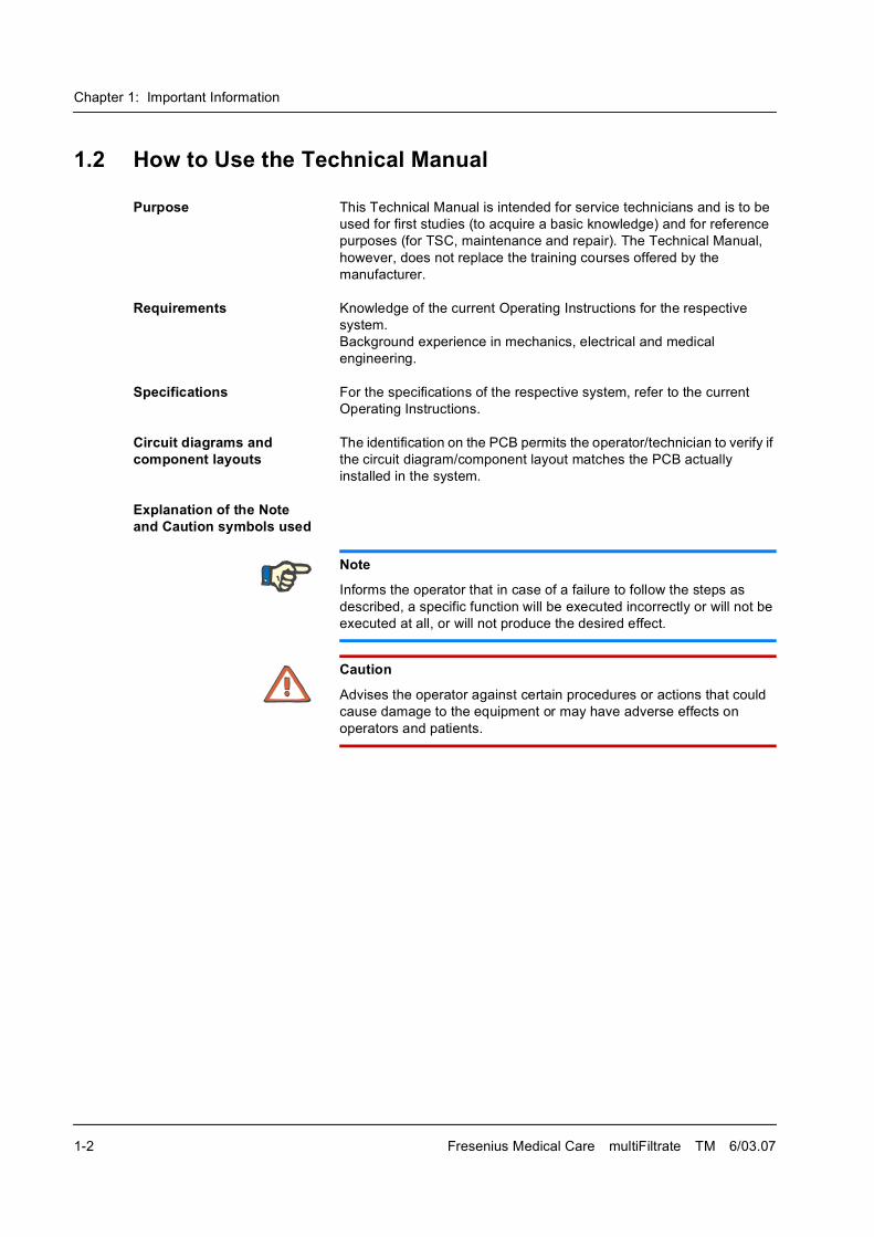
Explanation of the Note and Caution symbols used
Note
Informs the operator that in case of a failure to follow the steps as
described, a specific function will be executed incorrectly or will not be
executed at all, or will not produce the desired effect.
Caution
Advises the operator against certain procedures or actions that could
cause damage to the equipment or may have adverse effects on
operators and patients.
Chapter 1: Important Information
Fresenius Medical Care multiFiltrate TM 6/03.07 1-3
1.3 Precautions for Working on the System
Authorized persons Assembly, extensions, adjustments, modifications or repairs may only
be carried out by the manufacturer or persons authorized by him.
Test equipment and accessories
The activities described in the Technical Manual require the availability
of the necessary technical test equipment and accessories.
Precautions When working on the open system, the following precautions must be
respected:
� Protect the components against ingress of fluids.
� Do not touch live parts.
� All plugs, connections and components may only be disconnected or
connected if de-energized.
ESD precautions When repairing and when replacing spare parts, observe the applicable
ESD precautions (e.g. EN 100 015-1).
Chapter 1: Important Information
1-4 Fresenius Medical Care multiFiltrate TM 6/03.07
1.4 Addresses
Please address any inquiries to:
Manufacturer Fresenius Medical Care AG & Co. KGaA
D-61346 Bad Homburg
Germany
+49 (0)6172/609-0
www.fmc-ag.com
ServiceCentral Europe
Fresenius Medical Care
Deutschland GmbH
Geschäftsbereich Zentraleuropa
Kundendienst / Servicecenter
Steinmühlstrasse 24b
61352 Bad Homburg
Germany
Phone: +49 6172 609-7100
Fax: +49 6172 609-7102
E-mail: [email protected]
Internationalservice
Fresenius Medical Care
Deutschland GmbH
Service Support International
Hafenstrasse 9
D-97424 Schweinfurt
Germany
Phone: +49 9721 678-333 (hotline)
Fax: +49 9721 678-130
Local service
Chapter 2: Functional Description
Fresenius Medical Care multiFiltrate TM 6/03.07 2-1
2 Functional Description
2.1 Extracorporeal Circuit
The elements for maintaining and monitoring the extracorporeal circuit
of the multiFiltrate are as follows:
� Pumps
� Heaters
� Pressure transducer
� Air detector
� Venous clamp
� Non-opaque/opaque fluid detector
� Blood leak detector
� Heparin pump
2.1.1 Pumps
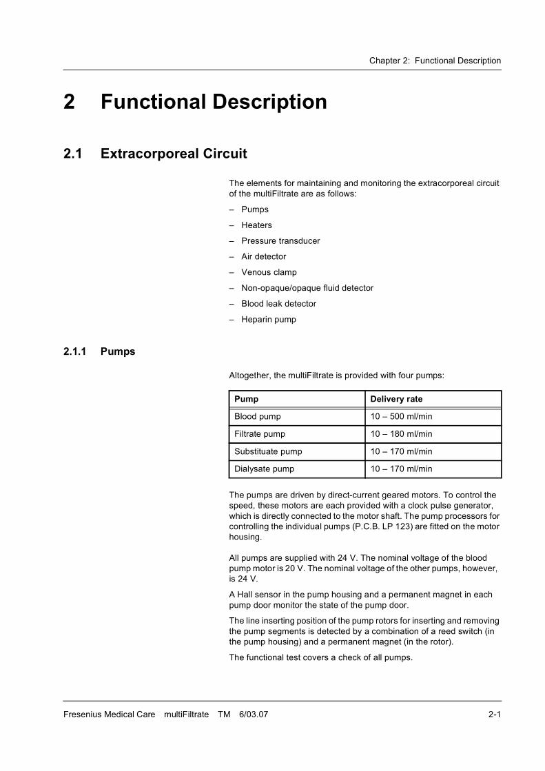
Altogether, the multiFiltrate is provided with four pumps:
The pumps are driven by direct-current geared motors. To control the
speed, these motors are each provided with a clock pulse generator,
which is directly connected to the motor shaft. The pump processors for
controlling the individual pumps (P.C.B. LP 123) are fitted on the motor
housing.
All pumps are supplied with 24 V. The nominal voltage of the blood
pump motor is 20 V. The nominal voltage of the other pumps, however,
is 24 V.
A Hall sensor in the pump housing and a permanent magnet in each
pump door monitor the state of the pump door.
The line inserting position of the pump rotors for inserting and removing
the pump segments is detected by a combination of a reed switch (in
the pump housing) and a permanent magnet (in the rotor).
The functional test covers a check of all pumps.
Pump Delivery rate
Blood pump 10 � 500 ml/min
Filtrate pump 10 � 180 ml/min
Substituate pump 10 � 170 ml/min
Dialysate pump 10 � 170 ml/min
Chapter 2: Functional Description
2-2 Fresenius Medical Care multiFiltrate TM 6/03.07
2.1.2 Heaters
To allow heating of replacement fluids, two heaters, which are activated
and monitored independently of each other, are installed in the
multiFiltrate.
The heater foil is applied to the outside of the heater rod and supplied
with approx. 28 V. The temperatures are controlled and monitored by
altogether four NTC sensors (two for the operating processor and two
for the safety processor). This is implemented on P.C.B. LP 122.
Both heaters are tested during the functional test.
2.1.3 Pressure Transducer
Four pressures are measured at the multiFiltrate:
� Arterial pressure,
Measuring transducer (P.C.B. LP 343-1) between the patient�s
arterial access and the blood pump
Measuring range: �280 � 300 mmHg
� Pre-hemofilter pressure
Measuring transducer (P.C.B. LP 343-1) between the blood pump
and the filter inlet
Measuring range: 0 � 750 mmHg
� Venous pressure,
Measuring transducer (P.C.B. LP 450-3) between the filter outlet
and the patient�s venous access,
Measuring range: �80 � 500 mmHg.
� Filtrate pressure or dialysate pressure
Measuring transducer (P.C.B. LP 343-1) between the filter
connector and the filtrate pump
Measuring range: �300 � 300mmHg.
All pressure transducers are subjected to the functional tests.
2.1.4 Air Detector and Venous Clamp
The air detector (P.C.B. LP 450-3) serves for the detection of air in the
extracorporeal blood circuit and operates on the ultrasound principle .
Both the transmitter and the receiver are integrated in the drip chamber
holder. Once the level in the venous drip chamber has fallen below a
certain threshold, the venous clamp is closed. This function is executed
independently of the operating or safety processor. The additional
board AD 28 increases the transmitter voltage during Preparation to
ensure that the level of saline solution is reliably detected.
The air detector is subjected to the functional test.
Chapter 2: Functional Description
Fresenius Medical Care multiFiltrate TM 6/03.07 2-3
2.1.5 Optical Detector (Non-Opaque/Opaque Fluid Detector)
The optical detector (P.C.B. LP 450-3) detects, according to the infrared
principle, whether saline solution or blood is present in the tubing
system.
The optical detector is subjected to the functional test.
2.1.6 Blood Leak Detector
The blood leak detector (P.C.B. LP 125) is provided for the detection of
a potential blood loss through the membrane. It is operated applying a
two-color measuring section. In the course of this, red and green light is
alternately transmitted to a reference receiver or, through the filtrate
line, to a measuring receiver.
Both the transmitter and the receiver are integrated in the line holder.
The blood leak detector is subjected to the functional test.
2.1.7 Heparin Pump
The heparin pump is used for continuous heparinization of the blood.
A syringe plunger is moved by means of a carriage bar. The carriage
bar is connected to a threaded spindle via a slide. A microprocessor-
controlled stepper motor causes the spindle to rotate. Depending on the
activation, the piston will move up or down.
One Hall sensor each signals when the piston has reached its upper
and lower end of travel. The safety system of the pump comprises a
speed monitoring device (slotted disc with optical sensor) and a motor
current monitoring function. The syringe types are set via a coding
switch (HEX switch).
2.2 Weighing Units
The weighing units are used for managing the fluid balance during
treatment.
The weighing cells are operated according to the strain gauge principle.
Signal conditioning, including analog-to-digital conversion, is achieved
per weighing cell on the P.C.B. LP 127. The actual weights are
produced by the operating processor.
Scale 1 and scale 2 each have a useful load of approx. 12 kg.
The scales are subjected to the functional test. To test the scales, a test
weight (ball) of defined value must be taken off each scale. Proper
functioning of the scales can be concluded from the correct difference
between the weights before and after lifting.
Chapter 2: Functional Description
2-4 Fresenius Medical Care multiFiltrate TM 6/03.07
2.3 Ci-Ca Module (Option)
The Ci-Ca module is intended for regional citrate anticoagulation in the
CVVHD treatment therapy.
Turning power on The Ci-Ca module requires a supply voltage of 24VDC. This voltage is
provided by the multiFiltrate system's power supply unit via the
connector in the lower IV pole support of the IV pole located on the right
of the system.
After the multiFiltrate system was turned on by pressing the power
switch on its rear, the supply voltage of the module is connected. The
operating processor of the Ci-Ca module switches into the standby
mode.
If the multiFiltrate systems is then turned on via the I/O key on the front
of the system, the operating processor of the Ci-Ca module will perform
an internal processor test. This test is performed simultaneously to the
processor test of the multiFiltrate system.
The Ci-Ca module communicates with the multiFiltrate basic system via
a serial interface.
Processor test If a test is not passed successfully, the module will not establish
communications with the multiFiltrate system. It is not possible to
perform a treatment with citrate anticoagulation. The multiFiltrate
system recognizes this problem and displays a message which
proposes to use an alternative anticoagulation equipment (e.g. heparin
pump) and which has to be confirmed by the operator.
T1 test The Ci-Ca module performs its own T1 test, independent of the T1 test
of the multiFiltrate system. This test will be started automatically and
simultaneously to the multiFiltrate T1 test after the prompt whether the
starting conditions are met was confirmed with [OK].
This test cannot be skipped or deselected.
System errors If it is still possible, system errors in the Ci-Ca module are shown on the
multiFiltrate display with the indication that citrate anticoagulation is not
available.
2.4 Functional Test (T1 Test) and Error Messages
After it has been turned on the rear and the [I/O] key has been pressed,
the system automatically starts the processor test. After completion of
the processor test, the display test will be performed. In this test, the
numerical characters are represented for 2 seconds in all of the three
fonts used. After this test, the functional test (T1 test) is started
automatically. Depending on the configuration in the SETUP (SETUP
automatic), the test is running in the background or (SETUP detailed)
the test steps are represented separately on the display.
Chapter 2: Functional Description
Fresenius Medical Care multiFiltrate TM 6/03.07 2-5
2.4.1 Battery Test, Part 1
At the beginning of the T1 test, the system assumes the terminal voltage
and loads the battery with a defined resistance over the entire test.
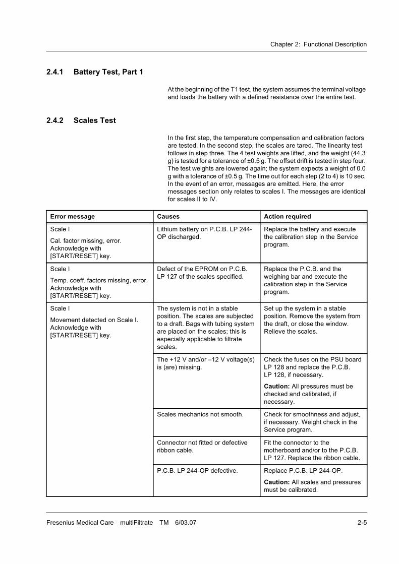
2.4.2 Scales Test
In the first step, the temperature compensation and calibration factors
are tested. In the second step, the scales are tared. The linearity test
follows in step three. The 4 test weights are lifted, and the weight (44.3
g) is tested for a tolerance of ±0.5 g. The offset drift is tested in step four.
The test weights are lowered again; the system expects a weight of 0.0
g with a tolerance of ±0.5 g. The time out for each step (2 to 4) is 10 sec.
In the event of an error, messages are emitted. Here, the error
messages section only relates to scales I. The messages are identical
for scales II to IV.
Error message Causes Action required
Scale I
Cal. factor missing, error.
Acknowledge with
[START/RESET] key.
Lithium battery on P.C.B. LP 244-
OP discharged.
Replace the battery and execute
the calibration step in the Service
program.
Scale I
Temp. coeff. factors missing, error.
Acknowledge with
[START/RESET] key.
Defect of the EPROM on P.C.B.
LP 127 of the scales specified.
Replace the P.C.B. and the
weighing bar and execute the
calibration step in the Service
program.
Scale I
Movement detected on Scale I.
Acknowledge with
[START/RESET] key.
The system is not in a stable
position. The scales are subjected
to a draft. Bags with tubing system
are placed on the scales; this is
especially applicable to filtrate
scales.
Set up the system in a stable
position. Remove the system from
the draft, or close the window.
Relieve the scales.
The +12 V and/or �12 V voltage(s)
is (are) missing.
Check the fuses on the PSU board
LP 128 and replace the P.C.B.
LP 128, if necessary.
Caution: All pressures must be
checked and calibrated, if
necessary.
Scales mechanics not smooth. Check for smoothness and adjust,
if necessary. Weight check in the
Service program.
Connector not fitted or defective
ribbon cable.
Fit the connector to the
motherboard and/or to the P.C.B.
LP 127. Replace the ribbon cable.
P.C.B. LP 244-OP defective. Replace P.C.B. LP 244-OP.
Caution: All scales and pressures
must be calibrated.
Chapter 2: Functional Description
2-6 Fresenius Medical Care multiFiltrate TM 6/03.07
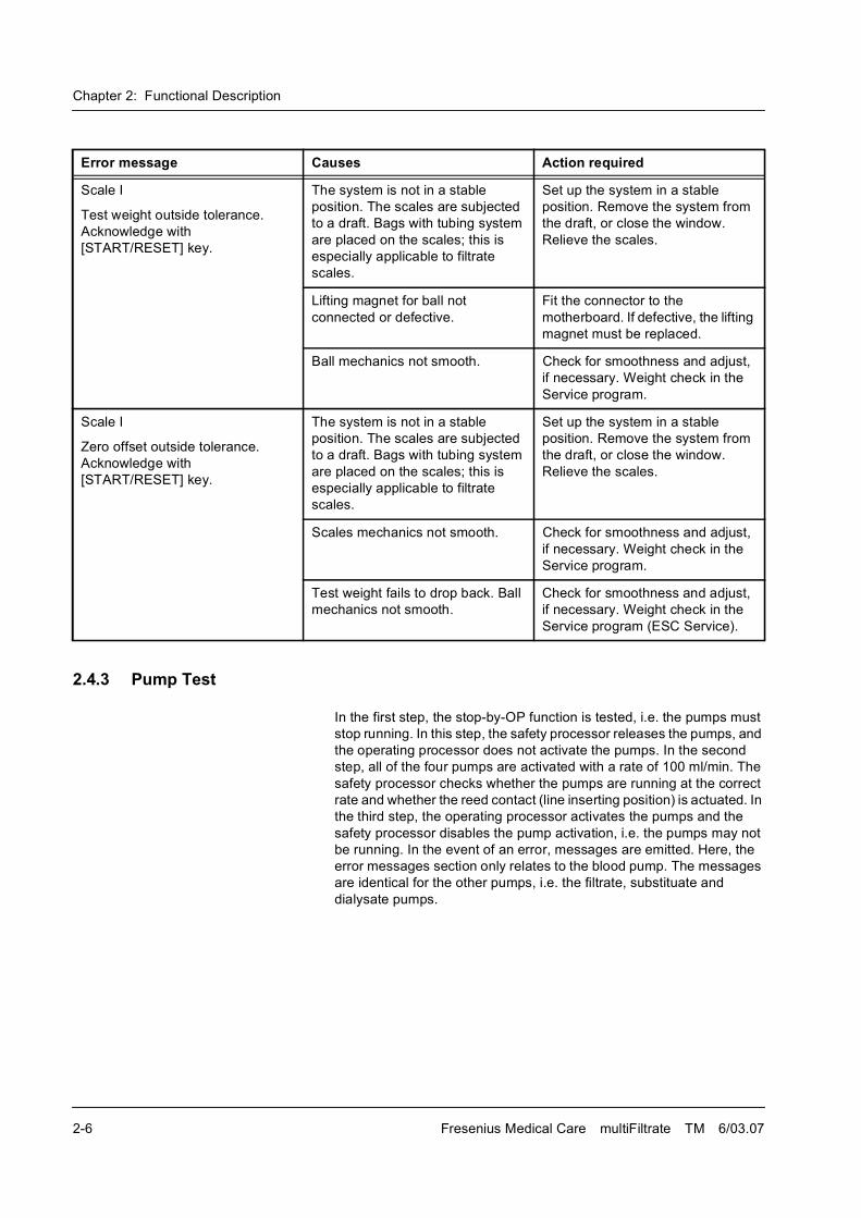
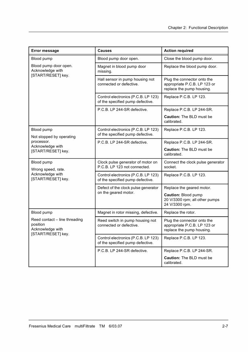
2.4.3 Pump Test
In the first step, the stop-by-OP function is tested, i.e. the pumps must
stop running. In this step, the safety processor releases the pumps, and
the operating processor does not activate the pumps. In the second
step, all of the four pumps are activated with a rate of 100 ml/min. The
safety processor checks whether the pumps are running at the correct
rate and whether the reed contact (line inserting position) is actuated. In
the third step, the operating processor activates the pumps and the
safety processor disables the pump activation, i.e. the pumps may not
be running. In the event of an error, messages are emitted. Here, the
error messages section only relates to the blood pump. The messages
are identical for the other pumps, i.e. the filtrate, substituate and
dialysate pumps.
Scale I
Test weight outside tolerance.
Acknowledge with
[START/RESET] key.
The system is not in a stable
position. The scales are subjected
to a draft. Bags with tubing system
are placed on the scales; this is
especially applicable to filtrate
scales.
Set up the system in a stable
position. Remove the system from
the draft, or close the window.
Relieve the scales.
Lifting magnet for ball not
connected or defective.
Fit the connector to the
motherboard. If defective, the lifting
magnet must be replaced.
Ball mechanics not smooth. Check for smoothness and adjust,
if necessary. Weight check in the
Service program.
Scale I
Zero offset outside tolerance.
Acknowledge with
[START/RESET] key.
The system is not in a stable
position. The scales are subjected
to a draft. Bags with tubing system
are placed on the scales; this is
especially applicable to filtrate
scales.
Set up the system in a stable
position. Remove the system from
the draft, or close the window.
Relieve the scales.
Scales mechanics not smooth. Check for smoothness and adjust,
if necessary. Weight check in the
Service program.
Test weight fails to drop back. Ball
mechanics not smooth.
Check for smoothness and adjust,
if necessary. Weight check in the
Service program (ESC Service).
Error message Causes Action required
Chapter 2: Functional Description
Fresenius Medical Care multiFiltrate TM 6/03.07 2-7
Error message Causes Action required
Blood pump
Blood pump door open.
Acknowledge with
[START/RESET] key.
Blood pump door open. Close the blood pump door.
Magnet in blood pump door
missing.
Replace the blood pump door.
Hall sensor in pump housing not
connected or defective.
Plug the connector onto the
appropriate P.C.B. LP 123 or
replace the pump housing.
Control electronics (P.C.B. LP 123)
of the specified pump defective.
Replace P.C.B. LP 123.
P.C.B. LP 244-SR defective. Replace P.C.B. LP 244-SR.
Caution: The BLD must be
calibrated.
Blood pump
Not stopped by operating
processor.
Acknowledge with
[START/RESET] key.
Control electronics (P.C.B. LP 123)
of the specified pump defective.
Replace P.C.B. LP 123.
P.C.B. LP 244-SR defective. Replace P.C.B. LP 244-SR.
Caution: The BLD must be
calibrated.
Blood pump
Wrong speed, rate.
Acknowledge with
[START/RESET] key.
Clock pulse generator of motor on
P.C.B. LP 123 not connected.
Connect the clock pulse generator
socket.
Control electronics (P.C.B. LP 123)
of the specified pump defective.
Replace P.C.B. LP 123.
Defect of the clock pulse generator
on the geared motor.
Replace the geared motor.
Caution: Blood pump
20 V/3300 rpm; all other pumps
24 V/3300 rpm.
Blood pump
Reed contact � line threading
position
Acknowledge with
[START/RESET] key.
Magnet in rotor missing, defective. Replace the rotor.
Reed switch in pump housing not
connected or defective.
Plug the connector onto the
appropriate P.C.B. LP 123 or
replace the pump housing.
Control electronics (P.C.B. LP 123)
of the specified pump defective.
Replace P.C.B. LP 123.
P.C.B. LP 244-SR defective. Replace P.C.B. LP 244-SR.
Caution: The BLD must be
calibrated.
Chapter 2: Functional Description
2-8 Fresenius Medical Care multiFiltrate TM 6/03.07
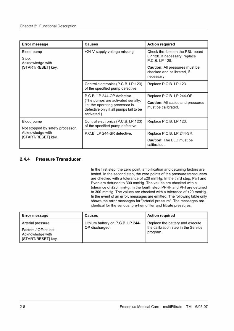
2.4.4 Pressure Transducer
In the first step, the zero point, amplification and detuning factors are
tested. In the second step, the zero points of the pressure transducers
are checked with a tolerance of ±20 mmHg. In the third step, Part and
Pven are detuned to 300 mmHg. The values are checked with a
tolerance of ±20 mmHg. In the fourth step, PPHF and PFil are detuned
to 300 mmHg. The values are checked with a tolerance of ±20 mmHg.
In the event of an error, messages are emitted. The following table only
shows the error messages for "arterial pressure". The messages are
identical for the venous, pre-hemofilter and filtrate pressures.
Blood pump
Stop.
Acknowledge with
[START/RESET] key.
+24-V supply voltage missing. Check the fuse on the PSU board
LP 128. If necessary, replace
P.C.B. LP 128.
Caution: All pressures must be
checked and calibrated, if
necessary.
Control electronics (P.C.B. LP 123)
of the specified pump defective.
Replace P.C.B. LP 123.
P.C.B. LP 244-OP defective.
(The pumps are activated serially,
i.e. the operating processor is
defective only if all pumps fail to be
activated.)
Replace P.C.B. LP 244-OP.
Caution: All scales and pressures
must be calibrated.
Blood pump
Not stopped by safety processor.
Acknowledge with
[START/RESET] key.
Control electronics (P.C.B. LP 123)
of the specified pump defective.
Replace P.C.B. LP 123.
P.C.B. LP 244-SR defective. Replace P.C.B. LP 244-SR.
Caution: The BLD must be
calibrated.
Error message Causes Action required
Error message Causes Action required
Arterial pressure
Factors / Offset lost.
Acknowledge with
[START/RESET] key.
Lithium battery on P.C.B. LP 244-
OP discharged.
Replace the battery and execute
the calibration step in the Service
program.
Chapter 2: Functional Description
Fresenius Medical Care multiFiltrate TM 6/03.07 2-9
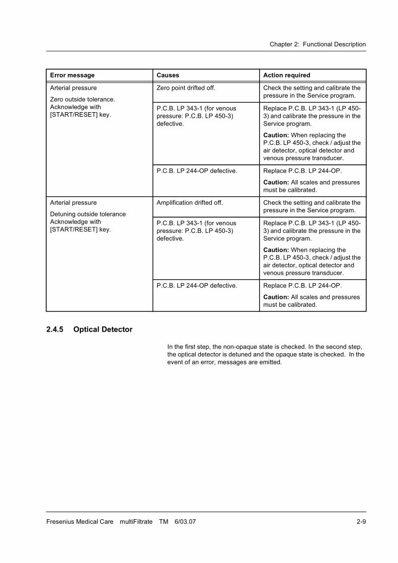
2.4.5 Optical Detector
In the first step, the non-opaque state is checked. In the second step,
the optical detector is detuned and the opaque state is checked. In the
event of an error, messages are emitted.
Arterial pressure
Zero outside tolerance.
Acknowledge with
[START/RESET] key.
Zero point drifted off. Check the setting and calibrate the
pressure in the Service program.
P.C.B. LP 343-1 (for venous
pressure: P.C.B. LP 450-3)
defective.
Replace P.C.B. LP 343-1 (LP 450-
3) and calibrate the pressure in the
Service program.
Caution: When replacing the
P.C.B. LP 450-3, check / adjust the
air detector, optical detector and
venous pressure transducer.
P.C.B. LP 244-OP defective. Replace P.C.B. LP 244-OP.
Caution: All scales and pressures
must be calibrated.
Arterial pressure
Detuning outside tolerance
Acknowledge with
[START/RESET] key.
Amplification drifted off. Check the setting and calibrate the
pressure in the Service program.
P.C.B. LP 343-1 (for venous
pressure: P.C.B. LP 450-3)
defective.
Replace P.C.B. LP 343-1 (LP 450-
3) and calibrate the pressure in the
Service program.
Caution: When replacing the
P.C.B. LP 450-3, check / adjust the
air detector, optical detector and
venous pressure transducer.
P.C.B. LP 244-OP defective. Replace P.C.B. LP 244-OP.
Caution: All scales and pressures
must be calibrated.
Error message Causes Action required
Chapter 2: Functional Description
2-10 Fresenius Medical Care multiFiltrate TM 6/03.07
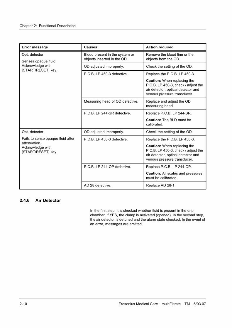
2.4.6 Air Detector
In the first step, it is checked whether fluid is present in the drip
chamber. if YES, the clamp is activated (opened). In the second step,
the air detector is detuned and the alarm state checked. In the event of
an error, messages are emitted.
Error message Causes Action required
Opt. detector
Senses opaque fluid.
Acknowledge with
[START/RESET] key.
Blood present in the system or
objects inserted in the OD.
Remove the blood line or the
objects from the OD.
OD adjusted improperly. Check the setting of the OD.
P.C.B. LP 450-3 defective. Replace the P.C.B. LP 450-3.
Caution: When replacing the
P.C.B. LP 450-3, check / adjust the
air detector, optical detector and
venous pressure transducer.
Measuring head of OD defective. Replace and adjust the OD
measuring head.
P.C.B. LP 244-SR defective. Replace P.C.B. LP 244-SR.
Caution: The BLD must be
calibrated.
Opt. detector
Fails to sense opaque fluid after
attenuation.
Acknowledge with
[START/RESET] key.
OD adjusted improperly. Check the setting of the OD.
P.C.B. LP 450-3 defective. Replace the P.C.B. LP 450-3.
Caution: When replacing the
P.C.B. LP 450-3, check / adjust the
air detector, optical detector and
venous pressure transducer.
P.C.B. LP 244-OP defective. Replace P.C.B. LP 244-OP.
Caution: All scales and pressures
must be calibrated.
AD 28 defective. Replace AD 28-1.
Chapter 2: Functional Description
Fresenius Medical Care multiFiltrate TM 6/03.07 2-11
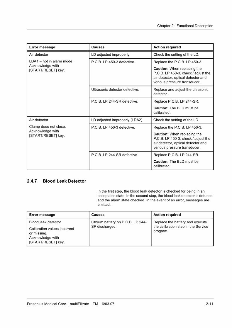
2.4.7 Blood Leak Detector
In the first step, the blood leak detector is checked for being in an
acceptable state. In the second step, the blood leak detector is detuned
and the alarm state checked. In the event of an error, messages are
emitted.
Error message Causes Action required
Air detector
LDA1 � not in alarm mode.
Acknowledge with
[START/RESET] key.
LD adjusted improperly. Check the setting of the LD.
P.C.B. LP 450-3 defective. Replace the P.C.B. LP 450-3.
Caution: When replacing the
P.C.B. LP 450-3, check / adjust the
air detector, optical detector and
venous pressure transducer.
Ultrasonic detector defective. Replace and adjust the ultrasonic
detector.
P.C.B. LP 244-SR defective. Replace P.C.B. LP 244-SR.
Caution: The BLD must be
calibrated.
Air detector
Clamp does not close.
Acknowledge with
[START/RESET] key.
LD adjusted improperly (LDA2). Check the setting of the LD.
P.C.B. LP 450-3 defective. Replace the P.C.B. LP 450-3.
Caution: When replacing the
P.C.B. LP 450-3, check / adjust the
air detector, optical detector and
venous pressure transducer.
P.C.B. LP 244-SR defective. Replace P.C.B. LP 244-SR.
Caution: The BLD must be
calibrated.
Error message Causes Action required
Blood leak detector
Calibration values incorrect
or missing.
Acknowledge with
[START/RESET] key.
Lithium battery on P.C.B. LP 244-
SP discharged.
Replace the battery and execute
the calibration step in the Service
program.
Chapter 2: Functional Description
2-12 Fresenius Medical Care multiFiltrate TM 6/03.07
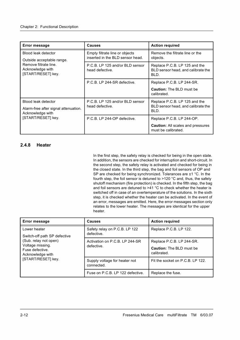
2.4.8 Heater
In the first step, the safety relay is checked for being in the open state.
In addition, the sensors are checked for interruption and short-circuit. In
the second step, the safety relay is activated and checked for being in
the closed state. In the third step, the bag and foil sensors of OP and
SP are checked for being synchronized. Tolerances are ±1 °C. In the
fourth step, the foil sensor is detuned to >120 °C and, thus, the safety
shutoff mechanism (fire protection) is checked. In the fifth step, the bag
and foil sensors are detuned to >41 °C to check whether the heater is
switched off in case of an overtemperature of the solutions. In the sixth
step, it is checked whether the heater can be activated. In the event of
an error, messages are emitted. Here, the error messages section only
relates to the lower heater. The messages are identical for the upper
heater.
Blood leak detector
Outside acceptable range.
Remove filtrate line.
Acknowledge with
[START/RESET] key.
Empty filtrate line or objects
inserted in the BLD sensor head.
Remove the filtrate line or the
objects.
P.C.B. LP 125 and/or BLD sensor
head defective.
Replace P.C.B. LP 125 and the
BLD sensor head, and calibrate the
BLD.
P.C.B. LP 244-SR defective. Replace P.C.B. LP 244-SR.
Caution: The BLD must be
calibrated.
Blood leak detector
Alarm-free after signal attenuation.
Acknowledge with
[START/RESET] key.
P.C.B. LP 125 and/or BLD sensor
head defective.
Replace P.C.B. LP 125 and the
BLD sensor head, and calibrate the
BLD.
P.C.B. LP 244-OP defective. Replace P.C.B. LP 244-OP.
Caution: All scales and pressures
must be calibrated.
Error message Causes Action required
Error message Causes Action required
Lower heater
Switch-off path SP defective
(Sub. relay not open)
Voltage missing.
Fuse defective.
Acknowledge with
[START/RESET] key.
Safety relay on P.C.B. LP 122
defective.
Replace P.C.B. LP 122.
Activation on P.C.B. LP 244-SR
defective.
Replace P.C.B. LP 244-SR.
Caution: The BLD must be
calibrated.
Supply voltage for heater not
connected.
Fit the socket on P.C.B. LP 122.
Fuse on P.C.B. LP 122 defective. Replace the fuse.
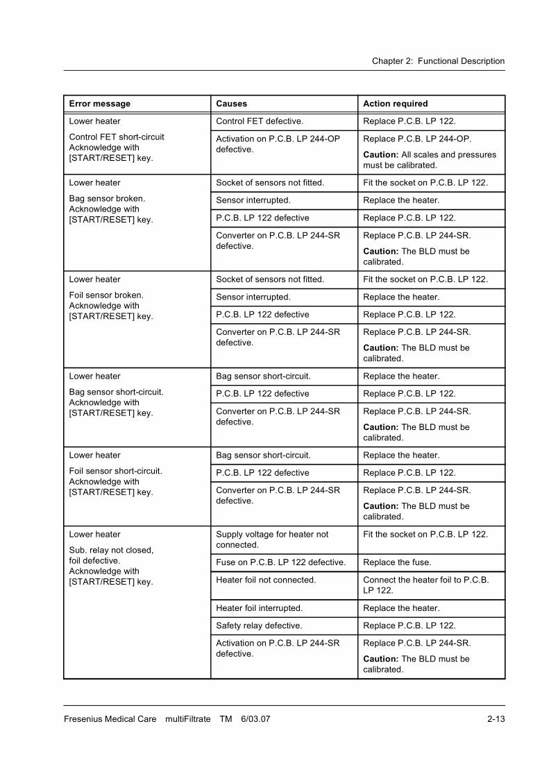
Chapter 2: Functional Description
Fresenius Medical Care multiFiltrate TM 6/03.07 2-13
Lower heater
Control FET short-circuit
Acknowledge with
[START/RESET] key.
Control FET defective. Replace P.C.B. LP 122.
Activation on P.C.B. LP 244-OP
defective.
Replace P.C.B. LP 244-OP.
Caution: All scales and pressures
must be calibrated.
Lower heater
Bag sensor broken.
Acknowledge with
[START/RESET] key.
Socket of sensors not fitted. Fit the socket on P.C.B. LP 122.
Sensor interrupted. Replace the heater.
P.C.B. LP 122 defective Replace P.C.B. LP 122.
Converter on P.C.B. LP 244-SR
defective.
Replace P.C.B. LP 244-SR.
Caution: The BLD must be
calibrated.
Lower heater
Foil sensor broken.
Acknowledge with
[START/RESET] key.
Socket of sensors not fitted. Fit the socket on P.C.B. LP 122.
Sensor interrupted. Replace the heater.
P.C.B. LP 122 defective Replace P.C.B. LP 122.
Converter on P.C.B. LP 244-SR
defective.
Replace P.C.B. LP 244-SR.
Caution: The BLD must be
calibrated.
Lower heater
Bag sensor short-circuit.
Acknowledge with
[START/RESET] key.
Bag sensor short-circuit. Replace the heater.
P.C.B. LP 122 defective Replace P.C.B. LP 122.
Converter on P.C.B. LP 244-SR
defective.
Replace P.C.B. LP 244-SR.
Caution: The BLD must be
calibrated.
Lower heater
Foil sensor short-circuit.
Acknowledge with
[START/RESET] key.
Bag sensor short-circuit. Replace the heater.
P.C.B. LP 122 defective Replace P.C.B. LP 122.
Converter on P.C.B. LP 244-SR
defective.
Replace P.C.B. LP 244-SR.
Caution: The BLD must be
calibrated.
Lower heater
Sub. relay not closed,
foil defective.
Acknowledge with
[START/RESET] key.
Supply voltage for heater not
connected.
Fit the socket on P.C.B. LP 122.
Fuse on P.C.B. LP 122 defective. Replace the fuse.
Heater foil not connected. Connect the heater foil to P.C.B.
LP 122.
Heater foil interrupted. Replace the heater.
Safety relay defective. Replace P.C.B. LP 122.
Activation on P.C.B. LP 244-SR
defective.
Replace P.C.B. LP 244-SR.
Caution: The BLD must be
calibrated.
Error message Causes Action required
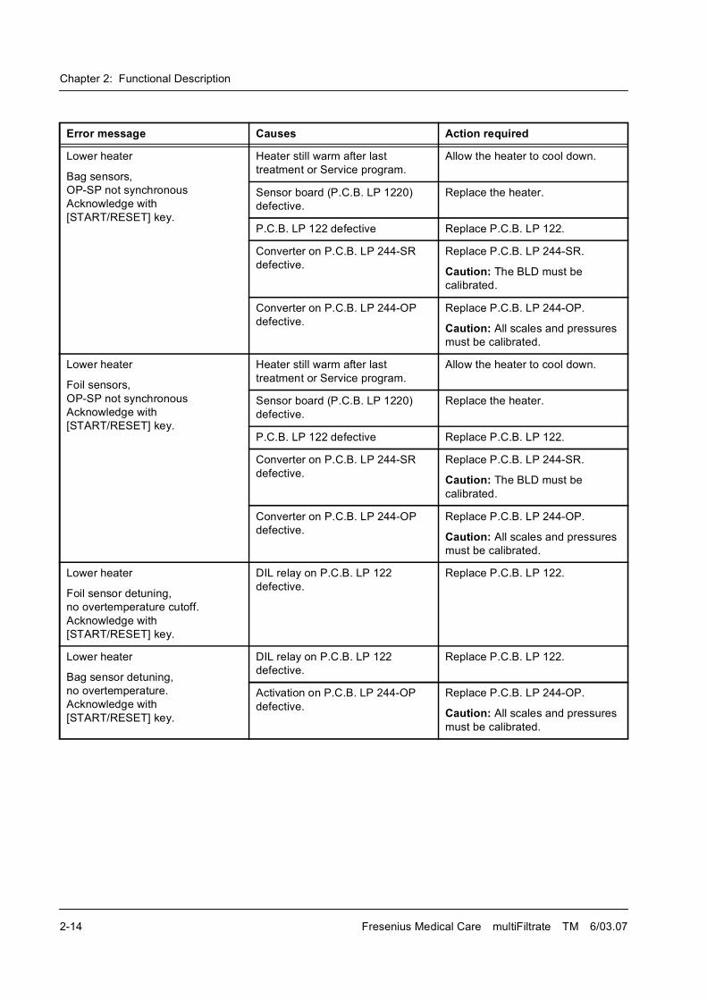
Chapter 2: Functional Description
2-14 Fresenius Medical Care multiFiltrate TM 6/03.07
Lower heater
Bag sensors,
OP-SP not synchronous
Acknowledge with
[START/RESET] key.
Heater still warm after last
treatment or Service program.
Allow the heater to cool down.
Sensor board (P.C.B. LP 1220)
defective.
Replace the heater.
P.C.B. LP 122 defective Replace P.C.B. LP 122.
Converter on P.C.B. LP 244-SR
defective.
Replace P.C.B. LP 244-SR.
Caution: The BLD must be
calibrated.
Converter on P.C.B. LP 244-OP
defective.
Replace P.C.B. LP 244-OP.
Caution: All scales and pressures
must be calibrated.
Lower heater
Foil sensors,
OP-SP not synchronous
Acknowledge with
[START/RESET] key.
Heater still warm after last
treatment or Service program.
Allow the heater to cool down.
Sensor board (P.C.B. LP 1220)
defective.
Replace the heater.
P.C.B. LP 122 defective Replace P.C.B. LP 122.
Converter on P.C.B. LP 244-SR
defective.
Replace P.C.B. LP 244-SR.
Caution: The BLD must be
calibrated.
Converter on P.C.B. LP 244-OP
defective.
Replace P.C.B. LP 244-OP.
Caution: All scales and pressures
must be calibrated.
Lower heater
Foil sensor detuning,
no overtemperature cutoff.
Acknowledge with
[START/RESET] key.
DIL relay on P.C.B. LP 122
defective.
Replace P.C.B. LP 122.
Lower heater
Bag sensor detuning,
no overtemperature.
Acknowledge with
[START/RESET] key.
DIL relay on P.C.B. LP 122
defective.
Replace P.C.B. LP 122.
Activation on P.C.B. LP 244-OP
defective.
Replace P.C.B. LP 244-OP.
Caution: All scales and pressures
must be calibrated.
Error message Causes Action required
Chapter 2: Functional Description
Fresenius Medical Care multiFiltrate TM 6/03.07 2-15
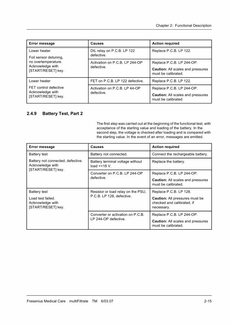
2.4.9 Battery Test, Part 2
The first step was carried out at the beginning of the functional test, with
acceptance of the starting value and loading of the battery. In the
second step, the voltage is checked after loading and is compared with
the starting value. In the event of an error, messages are emitted.
Lower heater
Foil sensor detuning,
no overtemperature.
Acknowledge with
[START/RESET] key.
DIL relay on P.C.B. LP 122
defective.
Replace P.C.B. LP 122.
Activation on P.C.B. LP 244-OP
defective.
Replace P.C.B. LP 244-OP.
Caution: All scales and pressures
must be calibrated.
Lower heater
FET control defective
Acknowledge with
[START/RESET] key.
FET on P.C.B. LP 122 defective. Replace P.C.B. LP 122.
Activation on P.C.B. LP 44-OP
defective.
Replace P.C.B. LP 244-OP.
Caution: All scales and pressures
must be calibrated.
Error message Causes Action required
Error message Causes Action required
Battery test
Battery not connected, defective.
Acknowledge with
[START/RESET] key.
Battery not connected. Connect the rechargeable battery.
Battery terminal voltage without
load <<18 V.
Replace the battery.
Converter on P.C.B. LP 244-OP
defective.
Replace P.C.B. LP 244-OP.
Caution: All scales and pressures
must be calibrated.
Battery test
Load test failed.
Acknowledge with
[START/RESET] key.
Resistor or load relay on the PSU,
P.C.B. LP 128, defective.
Replace P.C.B. LP 128.
Caution: All pressures must be
checked and calibrated, if
necessary.
Converter or activation on P.C.B.
LP 244-OP defective.
Replace P.C.B. LP 244-OP.
Caution: All scales and pressures
must be calibrated.
Chapter 2: Functional Description
2-16 Fresenius Medical Care multiFiltrate TM 6/03.07
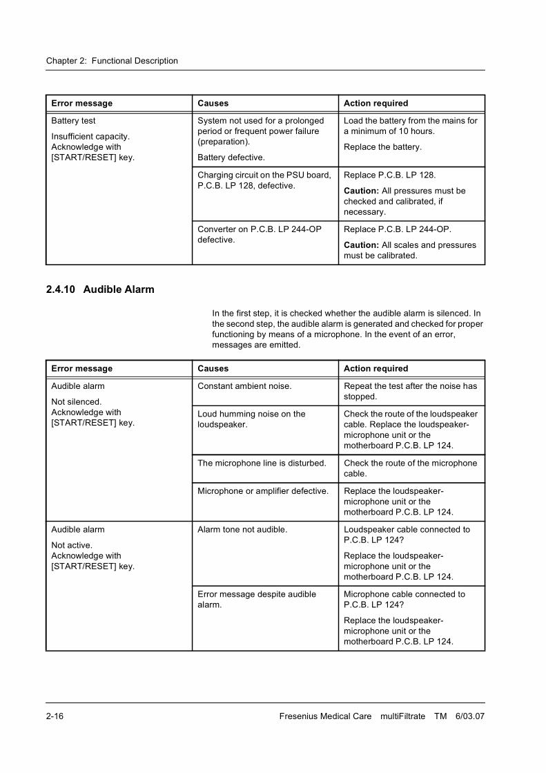
2.4.10 Audible Alarm
In the first step, it is checked whether the audible alarm is silenced. In
the second step, the audible alarm is generated and checked for proper
functioning by means of a microphone. In the event of an error,
messages are emitted.
Battery test
Insufficient capacity.
Acknowledge with
[START/RESET] key.
System not used for a prolonged
period or frequent power failure
(preparation).
Battery defective.
Load the battery from the mains for
a minimum of 10 hours.
Replace the battery.
Charging circuit on the PSU board,
P.C.B. LP 128, defective.
Replace P.C.B. LP 128.
Caution: All pressures must be
checked and calibrated, if
necessary.
Converter on P.C.B. LP 244-OP
defective.
Replace P.C.B. LP 244-OP.
Caution: All scales and pressures
must be calibrated.
Error message Causes Action required
Error message Causes Action required
Audible alarm
Not silenced.
Acknowledge with
[START/RESET] key.
Constant ambient noise. Repeat the test after the noise has
stopped.
Loud humming noise on the
loudspeaker.
Check the route of the loudspeaker
cable. Replace the loudspeaker-
microphone unit or the
motherboard P.C.B. LP 124.
The microphone line is disturbed. Check the route of the microphone
cable.
Microphone or amplifier defective. Replace the loudspeaker-
microphone unit or the
motherboard P.C.B. LP 124.
Audible alarm
Not active.
Acknowledge with
[START/RESET] key.
Alarm tone not audible. Loudspeaker cable connected to
P.C.B. LP 124?
Replace the loudspeaker-
microphone unit or the
motherboard P.C.B. LP 124.
Error message despite audible
alarm.
Microphone cable connected to
P.C.B. LP 124?
Replace the loudspeaker-
microphone unit or the
motherboard P.C.B. LP 124.
Chapter 2: Functional Description
Fresenius Medical Care multiFiltrate TM 6/03.07 2-17
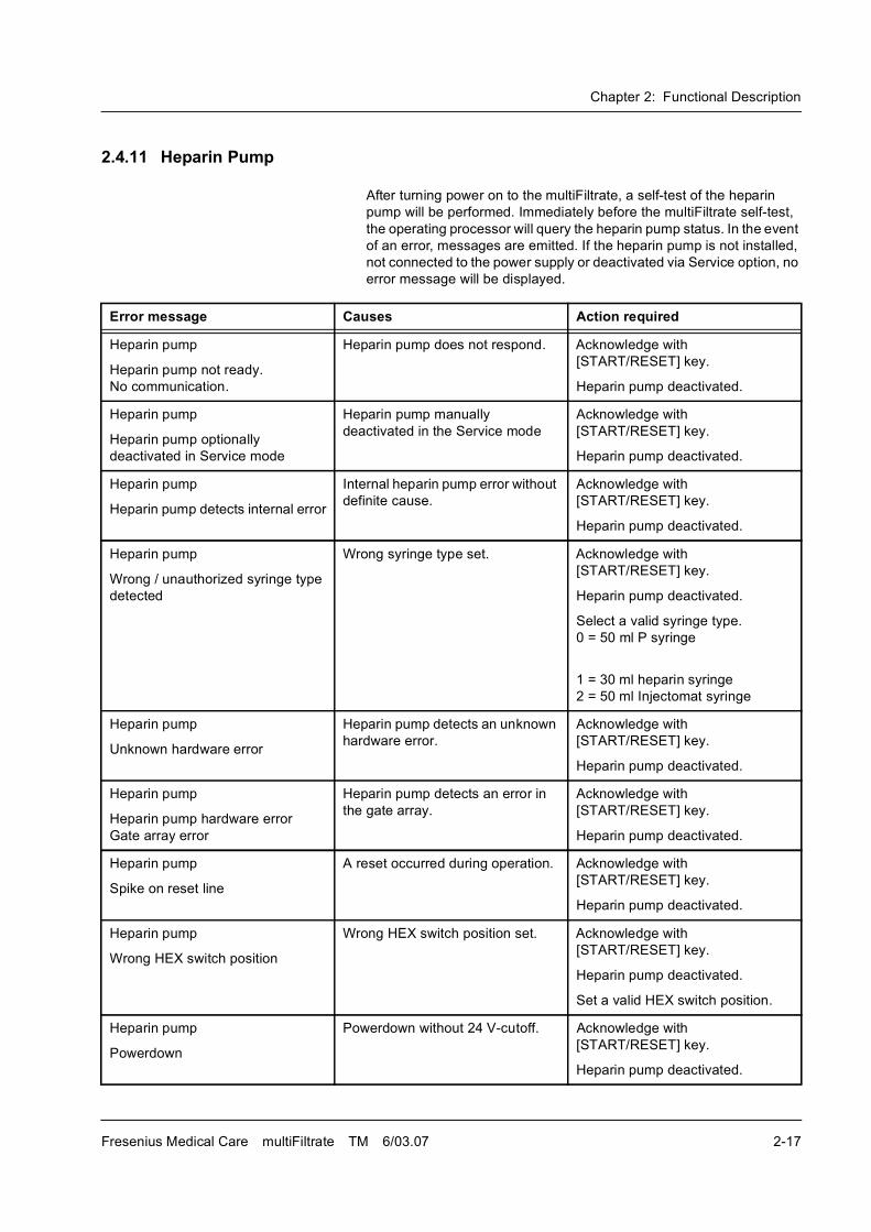
2.4.11 Heparin Pump
After turning power on to the multiFiltrate, a self-test of the heparin
pump will be performed. Immediately before the multiFiltrate self-test,
the operating processor will query the heparin pump status. In the event
of an error, messages are emitted. If the heparin pump is not installed,
not connected to the power supply or deactivated via Service option, no
error message will be displayed.
Error message Causes Action required
Heparin pump
Heparin pump not ready.
No communication.
Heparin pump does not respond. Acknowledge with
[START/RESET] key.
Heparin pump deactivated.
Heparin pump
Heparin pump optionally
deactivated in Service mode
Heparin pump manually
deactivated in the Service mode
Acknowledge with
[START/RESET] key.
Heparin pump deactivated.
Heparin pump
Heparin pump detects internal error
Internal heparin pump error without
definite cause.
Acknowledge with
[START/RESET] key.
Heparin pump deactivated.
Heparin pump
Wrong / unauthorized syringe type
detected
Wrong syringe type set. Acknowledge with
[START/RESET] key.
Heparin pump deactivated.
Select a valid syringe type.
0 = 50 ml P syringe
1 = 30 ml heparin syringe
2 = 50 ml Injectomat syringe
Heparin pump
Unknown hardware error
Heparin pump detects an unknown
hardware error.
Acknowledge with
[START/RESET] key.
Heparin pump deactivated.
Heparin pump
Heparin pump hardware error
Gate array error
Heparin pump detects an error in
the gate array.
Acknowledge with
[START/RESET] key.
Heparin pump deactivated.
Heparin pump
Spike on reset line
A reset occurred during operation. Acknowledge with
[START/RESET] key.
Heparin pump deactivated.
Heparin pump
Wrong HEX switch position
Wrong HEX switch position set. Acknowledge with
[START/RESET] key.
Heparin pump deactivated.
Set a valid HEX switch position.
Heparin pump
Powerdown
Powerdown without 24 V-cutoff. Acknowledge with
[START/RESET] key.
Heparin pump deactivated.
Chapter 2: Functional Description
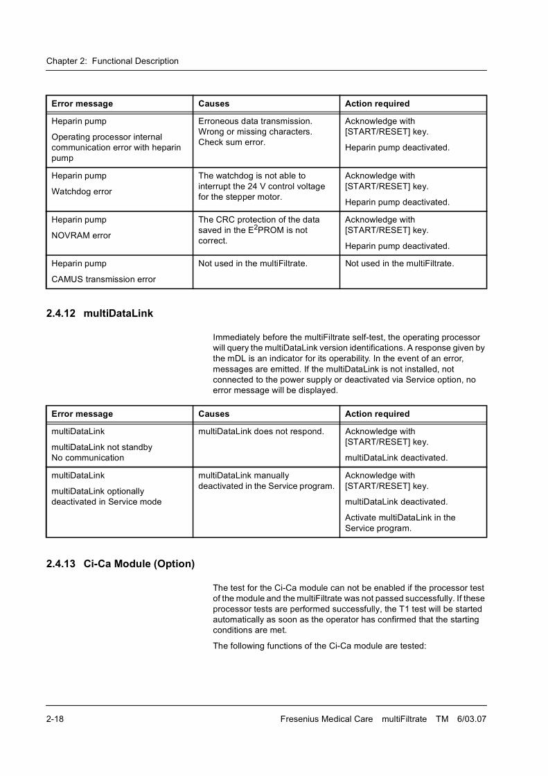
2-18 Fresenius Medical Care multiFiltrate TM 6/03.07
2.4.12 multiDataLink
Immediately before the multiFiltrate self-test, the operating processor
will query the multiDataLink version identifications. A response given by
the mDL is an indicator for its operability. In the event of an error,
messages are emitted. If the multiDataLink is not installed, not
connected to the power supply or deactivated via Service option, no
error message will be displayed.
2.4.13 Ci-Ca Module (Option)
The test for the Ci-Ca module can not be enabled if the processor test
of the module and the multiFiltrate was not passed successfully. If these
processor tests are performed successfully, the T1 test will be started
automatically as soon as the operator has confirmed that the starting
conditions are met.
The following functions of the Ci-Ca module are tested:
Heparin pump
Operating processor internal
communication error with heparin
pump
Erroneous data transmission.
Wrong or missing characters.
Check sum error.
Acknowledge with
[START/RESET] key.
Heparin pump deactivated.
Heparin pump
Watchdog error
The watchdog is not able to
interrupt the 24 V control voltage
for the stepper motor.
Acknowledge with
[START/RESET] key.
Heparin pump deactivated.
Heparin pump
NOVRAM error
The CRC protection of the data
saved in the E2PROM is not
correct.
Acknowledge with
[START/RESET] key.
Heparin pump deactivated.
Heparin pump
CAMUS transmission error
Not used in the multiFiltrate. Not used in the multiFiltrate.
Error message Causes Action required
Error message Causes Action required
multiDataLink
multiDataLink not standby
No communication
multiDataLink does not respond. Acknowledge with
[START/RESET] key.
multiDataLink deactivated.
multiDataLink
multiDataLink optionally
deactivated in Service mode
multiDataLink manually
deactivated in the Service program.
Acknowledge with
[START/RESET] key.
multiDataLink deactivated.
Activate multiDataLink in the
Service program.
Chapter 2: Functional Description
Fresenius Medical Care multiFiltrate TM 6/03.07 2-19
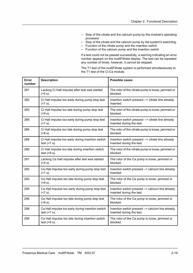
� Stop of the citrate and the calcium pump by the module's operating
processor
� Stop of the citrate and the calcium pump by the system's watchdog.
� Function of the citrate pump and the insertion switch
� Function of the calcium pump and the insertion switch
If a test could not be passed successfully, a warning indicating an error
number appears on the multiFiltrate display. The test can be repeated
any number of times, however, it cannot be skipped.
The T1 test of the multiFiltrate system is performed simultaneously to
the T1 test of the Ci-Ca module.
Error number
Description Possible cause
281 Lacking Ci Hall impulse after test was started
(>5 s).
The rotor of the citrate pump is loose, jammed or
blocked.
282 Ci Hall impulse too early during pump stop test
(<7 s).
Insertion switch pressed --> citrate line already
inserted.
283 Ci Hall impulse too late during pump stop test
(>9 s).
The rotor of the citrate pump is loose, jammed or
blocked.
285 Ci Hall impulse too early during pump stop test
(<7 s).
Insertion switch pressed --> citrate line already
inserted during the test.
286 Ci Hall impulse too late during pump stop test
(>9 s).
The rotor of the citrate pump is loose, jammed or
blocked.
288 Ci Hall impulse too early during insertion switch
test (<7 s).
Insertion switch pressed --> citrate line already
inserted during the test.
289 Ci Hall impulse too late during insertion switch
test (>9 s).
The rotor of the citrate pump is loose, jammed or
blocked.
291 Lacking Ca Hall impulse after test was started
(>5 s).
The rotor of the Ca pump is loose, jammed or
blocked.
292 Ca Hall impulse too early during pump stop test
(<7 s).
Insertion switch pressed --> calcium line already
inserted.
293 Ca Hall impulse too late during pump stop test
(>9 s).
The rotor of the Ca pump is loose, jammed or
blocked.
295 Ca Hall impulse too early during pump stop test
(<7 s).
Insertion switch pressed --> calcium line already
inserted during the test.
296 Ca Hall impulse too late during pump stop test
(>9 s).
The rotor of the Ca pump is loose, jammed or
blocked.
298 Ca Hall impulse too early during insertion switch
test (<7 s).
Insertion switch pressed --> calcium line already
inserted during the test.
299 Ca Hall impulse too late during insertion switch
test (>9 s).
The rotor of the Ca pump is loose, jammed or
blocked.
Chapter 2: Functional Description
2-20 Fresenius Medical Care multiFiltrate TM 6/03.07
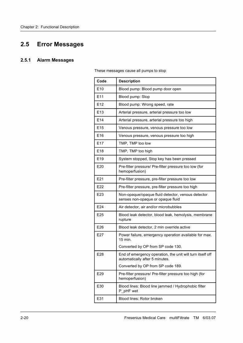
2.5 Error Messages
2.5.1 Alarm Messages
These messages cause all pumps to stop
Code Description
E10 Blood pump: Blood pump door open
E11 Blood pump: Stop
E12 Blood pump: Wrong speed, rate
E13 Arterial pressure, arterial pressure too low
E14 Arterial pressure, arterial pressure too high
E15 Venous pressure, venous pressure too low
E16 Venous pressure, venous pressure too high
E17 TMP, TMP too low
E18 TMP, TMP too high
E19 System stopped, Stop key has been pressed
E20 Pre-filter pressure/ Pre-filter pressure too low (for
hemoperfusion)
E21 Pre-filter pressure, pre-filter pressure too low
E22 Pre-filter pressure, pre-filter pressure too high
E23 Non-opaque/opaque fluid detector, venous detector
senses non-opaque or opaque fluid
E24 Air detector, air and/or microbubbles
E25 Blood leak detector, blood leak, hemolysis, membrane
rupture
E26 Blood leak detector, 2 min override active
E27 Power failure, emergency operation available for max.
15 min.
Converted by OP from SP code 130.
E28 End of emergency operation, the unit will turn itself off
automatically after 5 minutes.
Converted by OP from SP code 189.
E29 Pre-filter pressure/ Pre-filter pressure too high (for
hemoperfusion)
E30 Blood lines: Blood line jammed / Hydrophobic filter
P_pHF wet
E31 Blood lines: Rotor broken
Chapter 2: Functional Description
Fresenius Medical Care multiFiltrate TM 6/03.07 2-21
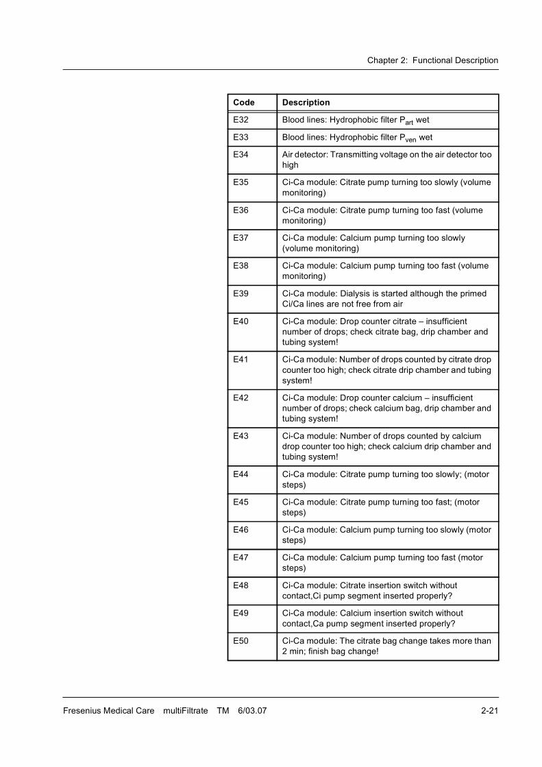
E32 Blood lines: Hydrophobic filter Part wet
E33 Blood lines: Hydrophobic filter Pven wet
E34 Air detector: Transmitting voltage on the air detector too
high
E35 Ci-Ca module: Citrate pump turning too slowly (volume
monitoring)
E36 Ci-Ca module: Citrate pump turning too fast (volume
monitoring)
E37 Ci-Ca module: Calcium pump turning too slowly
(volume monitoring)
E38 Ci-Ca module: Calcium pump turning too fast (volume
monitoring)
E39 Ci-Ca module: Dialysis is started although the primed
Ci/Ca lines are not free from air
E40 Ci-Ca module: Drop counter citrate � insufficient
number of drops; check citrate bag, drip chamber and
tubing system!
E41 Ci-Ca module: Number of drops counted by citrate drop
counter too high; check citrate drip chamber and tubing
system!
E42 Ci-Ca module: Drop counter calcium � insufficient
number of drops; check calcium bag, drip chamber and
tubing system!
E43 Ci-Ca module: Number of drops counted by calcium
drop counter too high; check calcium drip chamber and
tubing system!
E44 Ci-Ca module: Citrate pump turning too slowly; (motor
steps)
E45 Ci-Ca module: Citrate pump turning too fast; (motor
steps)
E46 Ci-Ca module: Calcium pump turning too slowly (motor
steps)
E47 Ci-Ca module: Calcium pump turning too fast (motor
steps)
E48 Ci-Ca module: Citrate insertion switch without
contact,Ci pump segment inserted properly?
E49 Ci-Ca module: Calcium insertion switch without
contact,Ca pump segment inserted properly?
E50 Ci-Ca module: The citrate bag change takes more than
2 min; finish bag change!
Code Description
Chapter 2: Functional Description
2-22 Fresenius Medical Care multiFiltrate TM 6/03.07
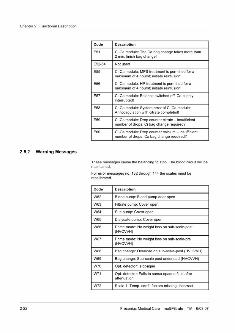
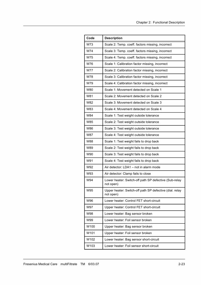
2.5.2 Warning Messages
These messages cause the balancing to stop. The blood circuit will be
maintained.
For error messages no. 132 through 144 the scales must be
recalibrated.
E51 Ci-Ca module: The Ca bag change takes more than
2 min; finish bag change!
E52-54 Not used
E55 Ci-Ca module: MPS treatment is permitted for a
maximum of 4 hours!; initiate reinfusion!
E56 Ci-Ca module: HP treatment is permitted for a
maximum of 4 hours!; initiate reinfusion!
E57 Ci-Ca module: Balance switched off; Ca supply
interrupted!
E58 Ci-Ca module: System error of Ci-Ca module:
Anitcoagulation with citrate completed!
E59 Ci-Ca module: Drop counter citrate � insufficient
number of drops; Ci bag change required?
E60 Ci-Ca module: Drop counter calcium � insufficient
number of drops; Ca bag change required?
Code Description
Code Description
W62 Blood pump: Blood pump door open
W63 Filtrate pump: Cover open
W64 Sub pump: Cover open
W65 Dialysate pump: Cover open
W66 Prime mode: No weight loss on sub-scale-post
(HVCVVH)
W67 Prime mode: No weight loss on sub-scale-pre
(HVCVVH)
W68 Bag change: Overload on sub-scale-post (HVCVVH)
W69 Bag change: Sub-scale post underload (HVCVVH)
W70 Opt. detector: is opaque
W71 Opt. detector: Fails to sense opaque fluid after
attenuation
W72 Scale 1: Temp. coeff. factors missing, incorrect
Chapter 2: Functional Description
Fresenius Medical Care multiFiltrate TM 6/03.07 2-23
W73 Scale 2: Temp. coeff. factors missing, incorrect
W74 Scale 3: Temp. coeff. factors missing, incorrect
W75 Scale 4: Temp. coeff. factors missing, incorrect
W76 Scale 1: Calibration factor missing, incorrect
W77 Scale 2: Calibration factor missing, incorrect
W78 Scale 3: Calibration factor missing, incorrect
W79 Scale 4: Calibration factor missing, incorrect
W80 Scale 1: Movement detected on Scale 1
W81 Scale 2: Movement detected on Scale 2
W82 Scale 3: Movement detected on Scale 3
W83 Scale 4: Movement detected on Scale 4
W84 Scale 1: Test weight outside tolerance
W85 Scale 2: Test weight outside tolerance
W86 Scale 3: Test weight outside tolerance
W87 Scale 4: Test weight outside tolerance
W88 Scale 1: Test weight fails to drop back
W89 Scale 2: Test weight fails to drop back
W90 Scale 3: Test weight fails to drop back
W91 Scale 4: Test weight fails to drop back
W92 Air detector: LDA1 � not in alarm mode
W93 Air detector: Clamp fails to close
W94 Lower heater: Switch-off path SP defective (Sub-relay
not open)
W95 Upper heater: Switch-off path SP defective (dial. relay
not open)
W96 Lower heater: Control FET short-circuit
W97 Upper heater: Control FET short-circuit
W98 Lower heater: Bag sensor broken
W99 Lower heater: Foil sensor broken
W100 Upper heater: Bag sensor broken
W101 Upper heater: Foil sensor broken
W102 Lower heater: Bag sensor short-circuit
W103 Lower heater: Foil sensor short-circuit
Code Description
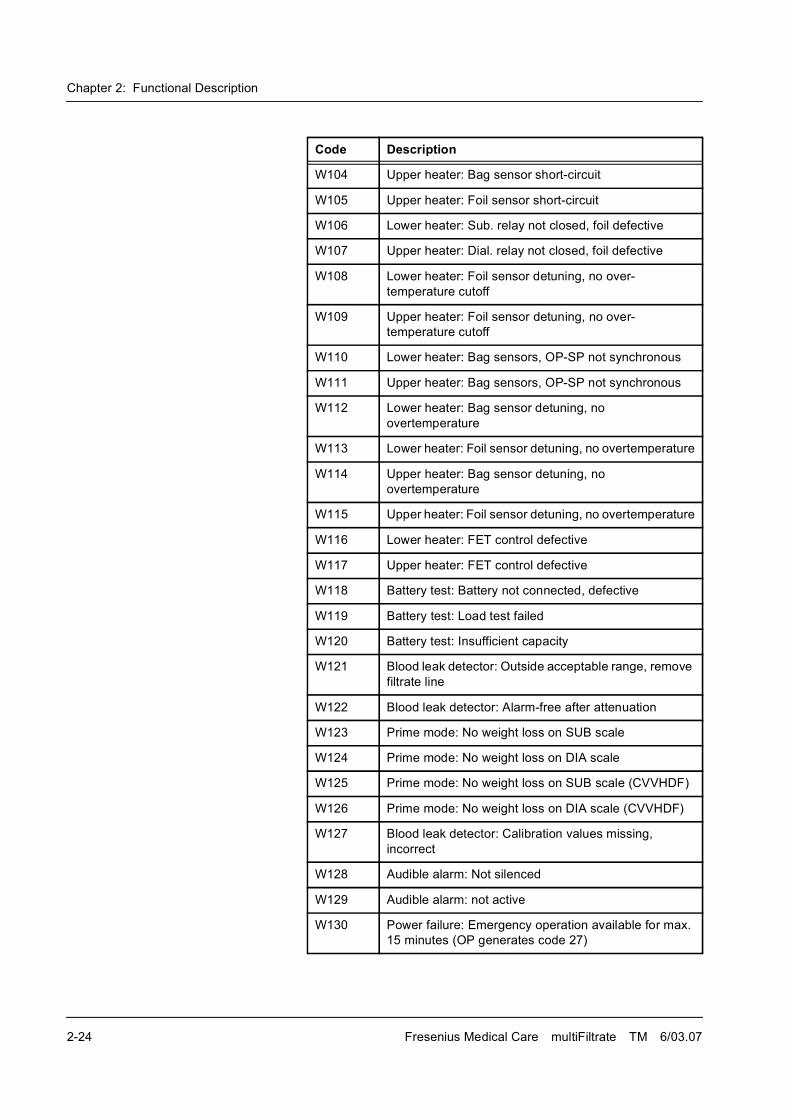
Chapter 2: Functional Description
2-24 Fresenius Medical Care multiFiltrate TM 6/03.07
W104 Upper heater: Bag sensor short-circuit
W105 Upper heater: Foil sensor short-circuit
W106 Lower heater: Sub. relay not closed, foil defective
W107 Upper heater: Dial. relay not closed, foil defective
W108 Lower heater: Foil sensor detuning, no over-
temperature cutoff
W109 Upper heater: Foil sensor detuning, no over-
temperature cutoff
W110 Lower heater: Bag sensors, OP-SP not synchronous
W111 Upper heater: Bag sensors, OP-SP not synchronous
W112 Lower heater: Bag sensor detuning, no
overtemperature
W113 Lower heater: Foil sensor detuning, no overtemperature
W114 Upper heater: Bag sensor detuning, no
overtemperature
W115 Upper heater: Foil sensor detuning, no overtemperature
W116 Lower heater: FET control defective
W117 Upper heater: FET control defective
W118 Battery test: Battery not connected, defective
W119 Battery test: Load test failed
W120 Battery test: Insufficient capacity
W121 Blood leak detector: Outside acceptable range, remove
filtrate line
W122 Blood leak detector: Alarm-free after attenuation
W123 Prime mode: No weight loss on SUB scale
W124 Prime mode: No weight loss on DIA scale
W125 Prime mode: No weight loss on SUB scale (CVVHDF)
W126 Prime mode: No weight loss on DIA scale (CVVHDF)
W127 Blood leak detector: Calibration values missing,
incorrect
W128 Audible alarm: Not silenced
W129 Audible alarm: not active
W130 Power failure: Emergency operation available for max.
15 minutes (OP generates code 27)
Code Description
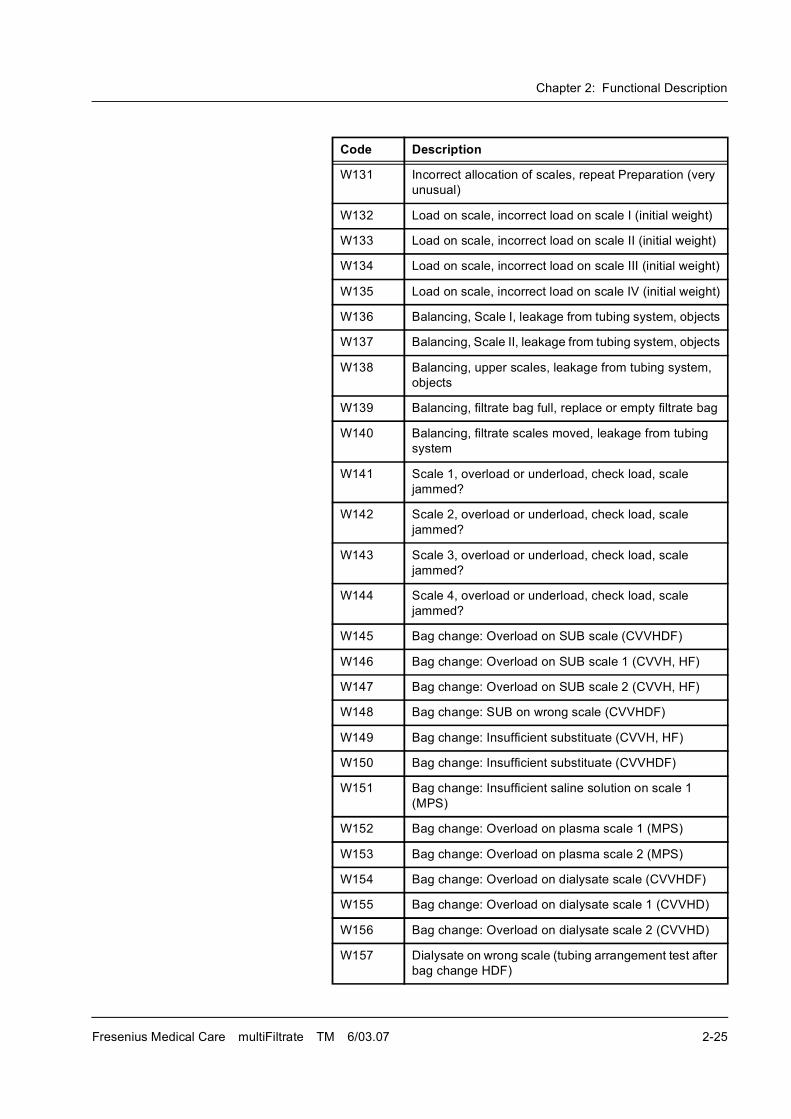
Chapter 2: Functional Description
Fresenius Medical Care multiFiltrate TM 6/03.07 2-25
W131 Incorrect allocation of scales, repeat Preparation (very
unusual)
W132 Load on scale, incorrect load on scale I (initial weight)
W133 Load on scale, incorrect load on scale II (initial weight)
W134 Load on scale, incorrect load on scale III (initial weight)
W135 Load on scale, incorrect load on scale IV (initial weight)
W136 Balancing, Scale I, leakage from tubing system, objects
W137 Balancing, Scale II, leakage from tubing system, objects
W138 Balancing, upper scales, leakage from tubing system,
objects
W139 Balancing, filtrate bag full, replace or empty filtrate bag
W140 Balancing, filtrate scales moved, leakage from tubing
system
W141 Scale 1, overload or underload, check load, scale
jammed?
W142 Scale 2, overload or underload, check load, scale
jammed?
W143 Scale 3, overload or underload, check load, scale
jammed?
W144 Scale 4, overload or underload, check load, scale
jammed?
W145 Bag change: Overload on SUB scale (CVVHDF)
W146 Bag change: Overload on SUB scale 1 (CVVH, HF)
W147 Bag change: Overload on SUB scale 2 (CVVH, HF)
W148 Bag change: SUB on wrong scale (CVVHDF)
W149 Bag change: Insufficient substituate (CVVH, HF)
W150 Bag change: Insufficient substituate (CVVHDF)
W151 Bag change: Insufficient saline solution on scale 1
(MPS)
W152 Bag change: Overload on plasma scale 1 (MPS)
W153 Bag change: Overload on plasma scale 2 (MPS)
W154 Bag change: Overload on dialysate scale (CVVHDF)
W155 Bag change: Overload on dialysate scale 1 (CVVHD)
W156 Bag change: Overload on dialysate scale 2 (CVVHD)
W157 Dialysate on wrong scale (tubing arrangement test after
bag change HDF)
Code Description
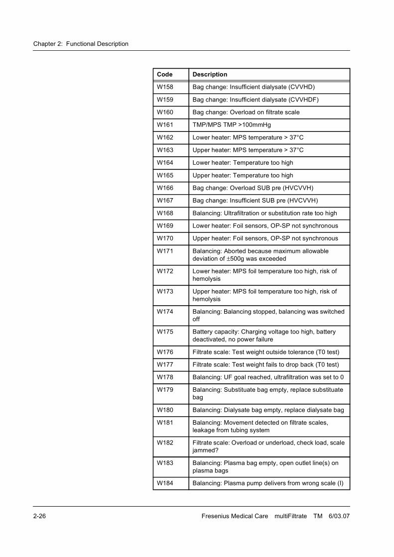
Chapter 2: Functional Description
2-26 Fresenius Medical Care multiFiltrate TM 6/03.07
W158 Bag change: Insufficient dialysate (CVVHD)
W159 Bag change: Insufficient dialysate (CVVHDF)
W160 Bag change: Overload on filtrate scale
W161 TMP/MPS TMP >100mmHg
W162 Lower heater: MPS temperature > 37°C
W163 Upper heater: MPS temperature > 37°C
W164 Lower heater: Temperature too high
W165 Upper heater: Temperature too high
W166 Bag change: Overload SUB pre (HVCVVH)
W167 Bag change: Insufficient SUB pre (HVCVVH)
W168 Balancing: Ultrafiltration or substitution rate too high
W169 Lower heater: Foil sensors, OP-SP not synchronous
W170 Upper heater: Foil sensors, OP-SP not synchronous
W171 Balancing: Aborted because maximum allowable
deviation of �500g was exceeded
W172 Lower heater: MPS foil temperature too high, risk of
hemolysis
W173 Upper heater: MPS foil temperature too high, risk of
hemolysis
W174 Balancing: Balancing stopped, balancing was switched
off
W175 Battery capacity: Charging voltage too high, battery
deactivated, no power failure
W176 Filtrate scale: Test weight outside tolerance (T0 test)
W177 Filtrate scale: Test weight fails to drop back (T0 test)
W178 Balancing: UF goal reached, ultrafiltration was set to 0
W179 Balancing: Substituate bag empty, replace substituate
bag
W180 Balancing: Dialysate bag empty, replace dialysate bag
W181 Balancing: Movement detected on filtrate scales,
leakage from tubing system
W182 Filtrate scale: Overload or underload, check load, scale
jammed?
W183 Balancing: Plasma bag empty, open outlet line(s) on
plasma bags
W184 Balancing: Plasma pump delivers from wrong scale (I)
Code Description
Chapter 2: Functional Description
Fresenius Medical Care multiFiltrate TM 6/03.07 2-27
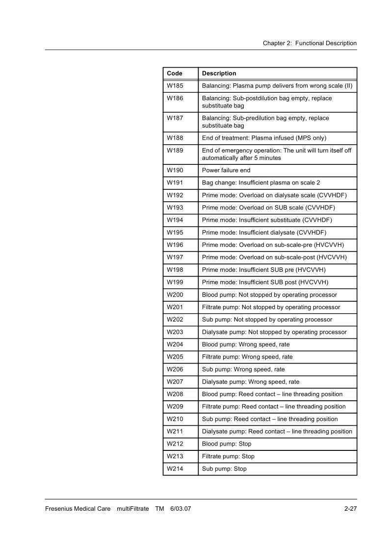
W185 Balancing: Plasma pump delivers from wrong scale (II)
W186 Balancing: Sub-postdilution bag empty, replace
substituate bag
W187 Balancing: Sub-predilution bag empty, replace
substituate bag
W188 End of treatment: Plasma infused (MPS only)
W189 End of emergency operation: The unit will turn itself off
automatically after 5 minutes
W190 Power failure end
W191 Bag change: Insufficient plasma on scale 2
W192 Prime mode: Overload on dialysate scale (CVVHDF)
W193 Prime mode: Overload on SUB scale (CVVHDF)
W194 Prime mode: Insufficient substituate (CVVHDF)
W195 Prime mode: Insufficient dialysate (CVVHDF)
W196 Prime mode: Overload on sub-scale-pre (HVCVVH)
W197 Prime mode: Overload on sub-scale-post (HVCVVH)
W198 Prime mode: Insufficient SUB pre (HVCVVH)
W199 Prime mode: Insufficient SUB post (HVCVVH)
W200 Blood pump: Not stopped by operating processor
W201 Filtrate pump: Not stopped by operating processor
W202 Sub pump: Not stopped by operating processor
W203 Dialysate pump: Not stopped by operating processor
W204 Blood pump: Wrong speed, rate
W205 Filtrate pump: Wrong speed, rate
W206 Sub pump: Wrong speed, rate
W207 Dialysate pump: Wrong speed, rate
W208 Blood pump: Reed contact � line threading position
W209 Filtrate pump: Reed contact � line threading position
W210 Sub pump: Reed contact � line threading position
W211 Dialysate pump: Reed contact � line threading position
W212 Blood pump: Stop
W213 Filtrate pump: Stop
W214 Sub pump: Stop
Code Description
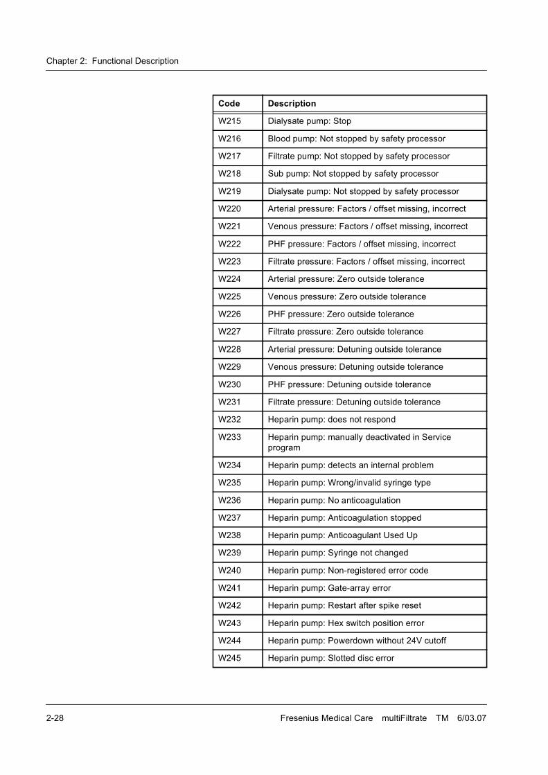
Chapter 2: Functional Description
2-28 Fresenius Medical Care multiFiltrate TM 6/03.07
W215 Dialysate pump: Stop
W216 Blood pump: Not stopped by safety processor
W217 Filtrate pump: Not stopped by safety processor
W218 Sub pump: Not stopped by safety processor
W219 Dialysate pump: Not stopped by safety processor
W220 Arterial pressure: Factors / offset missing, incorrect
W221 Venous pressure: Factors / offset missing, incorrect
W222 PHF pressure: Factors / offset missing, incorrect
W223 Filtrate pressure: Factors / offset missing, incorrect
W224 Arterial pressure: Zero outside tolerance
W225 Venous pressure: Zero outside tolerance
W226 PHF pressure: Zero outside tolerance
W227 Filtrate pressure: Zero outside tolerance
W228 Arterial pressure: Detuning outside tolerance
W229 Venous pressure: Detuning outside tolerance
W230 PHF pressure: Detuning outside tolerance
W231 Filtrate pressure: Detuning outside tolerance
W232 Heparin pump: does not respond
W233 Heparin pump: manually deactivated in Service
program
W234 Heparin pump: detects an internal problem
W235 Heparin pump: Wrong/invalid syringe type
W236 Heparin pump: No anticoagulation
W237 Heparin pump: Anticoagulation stopped
W238 Heparin pump: Anticoagulant Used Up
W239 Heparin pump: Syringe not changed
W240 Heparin pump: Non-registered error code
W241 Heparin pump: Gate-array error
W242 Heparin pump: Restart after spike reset
W243 Heparin pump: Hex switch position error
W244 Heparin pump: Powerdown without 24V cutoff
W245 Heparin pump: Slotted disc error
Code Description
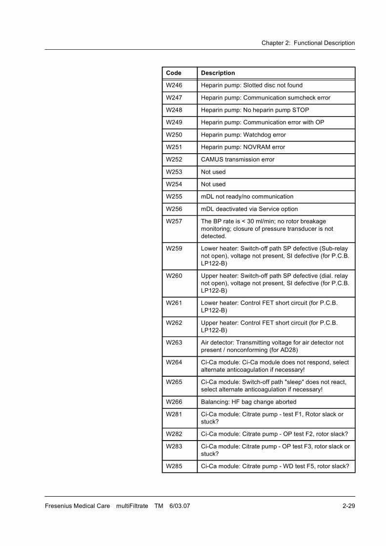
Chapter 2: Functional Description
Fresenius Medical Care multiFiltrate TM 6/03.07 2-29
W246 Heparin pump: Slotted disc not found
W247 Heparin pump: Communication sumcheck error
W248 Heparin pump: No heparin pump STOP
W249 Heparin pump: Communication error with OP
W250 Heparin pump: Watchdog error
W251 Heparin pump: NOVRAM error
W252 CAMUS transmission error
W253 Not used
W254 Not used
W255 mDL not ready/no communication
W256 mDL deactivated via Service option
W257 The BP rate is < 30 ml/min; no rotor breakage
monitoring; closure of pressure transducer is not
detected.
W259 Lower heater: Switch-off path SP defective (Sub-relay
not open), voltage not present, SI defective (for P.C.B.
LP122-B)
W260 Upper heater: Switch-off path SP defective (dial. relay
not open), voltage not present, SI defective (for P.C.B.
LP122-B)
W261 Lower heater: Control FET short circuit (for P.C.B.
LP122-B)
W262 Upper heater: Control FET short circuit (for P.C.B.
LP122-B)
W263 Air detector: Transmitting voltage for air detector not
present / nonconforming (for AD28)
W264 Ci-Ca module: Ci-Ca module does not respond, select
alternate anticoagulation if necessary!
W265 Ci-Ca module: Switch-off path "sleep" does not react,
select alternate anticoagulation if necessary!
W266 Balancing: HF bag change aborted
W281 Ci-Ca module: Citrate pump - test F1, Rotor slack or
stuck?
W282 Ci-Ca module: Citrate pump - OP test F2, rotor slack?
W283 Ci-Ca module: Citrate pump - OP test F3, rotor slack or
stuck?
W285 Ci-Ca module: Citrate pump - WD test F5, rotor slack?
Code Description
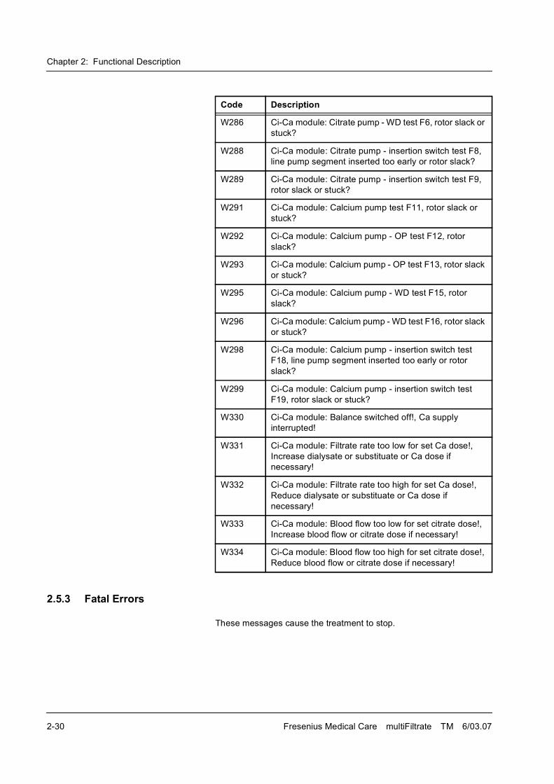
Chapter 2: Functional Description
2-30 Fresenius Medical Care multiFiltrate TM 6/03.07
2.5.3 Fatal Errors
These messages cause the treatment to stop.
W286 Ci-Ca module: Citrate pump - WD test F6, rotor slack or
stuck?
W288 Ci-Ca module: Citrate pump - insertion switch test F8,
line pump segment inserted too early or rotor slack?
W289 Ci-Ca module: Citrate pump - insertion switch test F9,
rotor slack or stuck?
W291 Ci-Ca module: Calcium pump test F11, rotor slack or
stuck?
W292 Ci-Ca module: Calcium pump - OP test F12, rotor
slack?
W293 Ci-Ca module: Calcium pump - OP test F13, rotor slack
or stuck?
W295 Ci-Ca module: Calcium pump - WD test F15, rotor
slack?
W296 Ci-Ca module: Calcium pump - WD test F16, rotor slack
or stuck?
W298 Ci-Ca module: Calcium pump - insertion switch test
F18, line pump segment inserted too early or rotor
slack?
W299 Ci-Ca module: Calcium pump - insertion switch test
F19, rotor slack or stuck?
W330 Ci-Ca module: Balance switched off!, Ca supply
interrupted!
W331 Ci-Ca module: Filtrate rate too low for set Ca dose!,
Increase dialysate or substituate or Ca dose if
necessary!
W332 Ci-Ca module: Filtrate rate too high for set Ca dose!,
Reduce dialysate or substituate or Ca dose if
necessary!
W333 Ci-Ca module: Blood flow too low for set citrate dose!,
Increase blood flow or citrate dose if necessary!
W334 Ci-Ca module: Blood flow too high for set citrate dose!,
Reduce blood flow or citrate dose if necessary!
Code Description
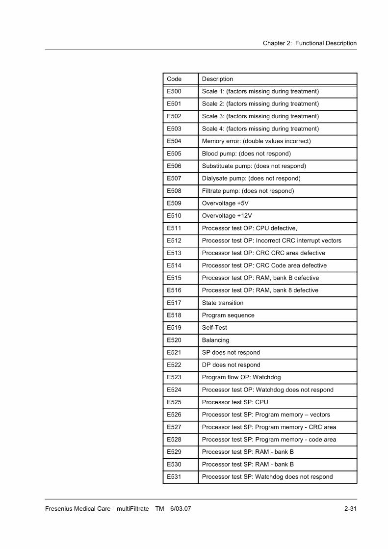
Chapter 2: Functional Description
Fresenius Medical Care multiFiltrate TM 6/03.07 2-31
Code Description
E500 Scale 1: (factors missing during treatment)
E501 Scale 2: (factors missing during treatment)
E502 Scale 3: (factors missing during treatment)
E503 Scale 4: (factors missing during treatment)
E504 Memory error: (double values incorrect)
E505 Blood pump: (does not respond)
E506 Substituate pump: (does not respond)
E507 Dialysate pump: (does not respond)
E508 Filtrate pump: (does not respond)
E509 Overvoltage +5V
E510 Overvoltage +12V
E511 Processor test OP: CPU defective,
E512 Processor test OP: Incorrect CRC interrupt vectors
E513 Processor test OP: CRC CRC area defective
E514 Processor test OP: CRC Code area defective
E515 Processor test OP: RAM, bank B defective
E516 Processor test OP: RAM, bank 8 defective
E517 State transition
E518 Program sequence
E519 Self-Test
E520 Balancing
E521 SP does not respond
E522 DP does not respond
E523 Program flow OP: Watchdog
E524 Processor test OP: Watchdog does not respond
E525 Processor test SP: CPU
E526 Processor test SP: Program memory � vectors
E527 Processor test SP: Program memory - CRC area
E528 Processor test SP: Program memory - code area
E529 Processor test SP: RAM - bank B
E530 Processor test SP: RAM - bank B
E531 Processor test SP: Watchdog does not respond
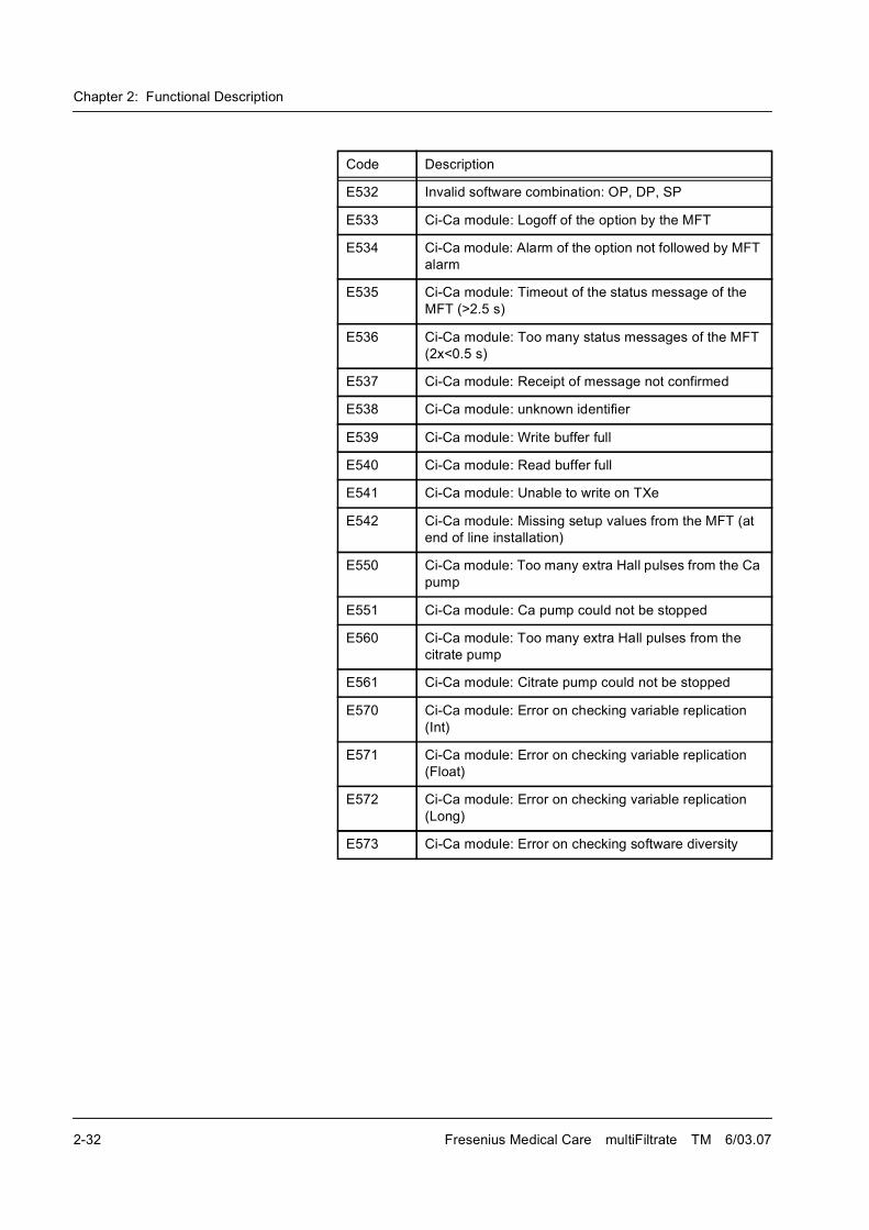
Chapter 2: Functional Description
2-32 Fresenius Medical Care multiFiltrate TM 6/03.07
E532 Invalid software combination: OP, DP, SP
E533 Ci-Ca module: Logoff of the option by the MFT
E534 Ci-Ca module: Alarm of the option not followed by MFT
alarm
E535 Ci-Ca module: Timeout of the status message of the
MFT (>2.5 s)
E536 Ci-Ca module: Too many status messages of the MFT
(2x<0.5 s)
E537 Ci-Ca module: Receipt of message not confirmed
E538 Ci-Ca module: unknown identifier
E539 Ci-Ca module: Write buffer full
E540 Ci-Ca module: Read buffer full
E541 Ci-Ca module: Unable to write on TXe
E542 Ci-Ca module: Missing setup values from the MFT (at
end of line installation)
E550 Ci-Ca module: Too many extra Hall pulses from the Ca
pump
E551 Ci-Ca module: Ca pump could not be stopped
E560 Ci-Ca module: Too many extra Hall pulses from the
citrate pump
E561 Ci-Ca module: Citrate pump could not be stopped
E570 Ci-Ca module: Error on checking variable replication
(Int)
E571 Ci-Ca module: Error on checking variable replication
(Float)
E572 Ci-Ca module: Error on checking variable replication
(Long)
E573 Ci-Ca module: Error on checking software diversity
Code Description
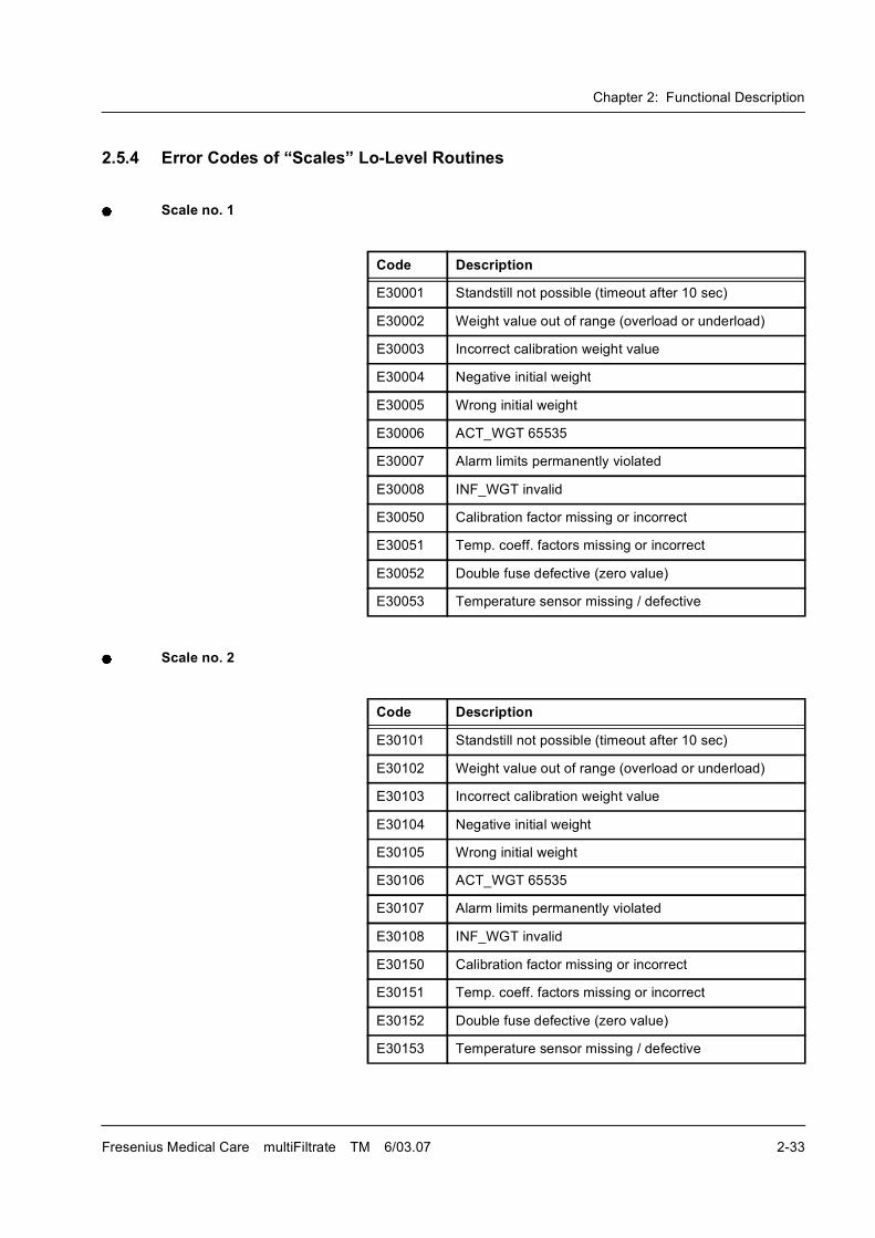
Chapter 2: Functional Description
Fresenius Medical Care multiFiltrate TM 6/03.07 2-33
2.5.4 Error Codes of �Scales� Lo-Level Routines
Scale no. 1
Scale no. 2
Code Description
E30001 Standstill not possible (timeout after 10 sec)
E30002 Weight value out of range (overload or underload)
E30003 Incorrect calibration weight value
E30004 Negative initial weight
E30005 Wrong initial weight
E30006 ACT_WGT 65535
E30007 Alarm limits permanently violated
E30008 INF_WGT invalid
E30050 Calibration factor missing or incorrect
E30051 Temp. coeff. factors missing or incorrect
E30052 Double fuse defective (zero value)
E30053 Temperature sensor missing / defective
Code Description
E30101 Standstill not possible (timeout after 10 sec)
E30102 Weight value out of range (overload or underload)
E30103 Incorrect calibration weight value
E30104 Negative initial weight
E30105 Wrong initial weight
E30106 ACT_WGT 65535
E30107 Alarm limits permanently violated
E30108 INF_WGT invalid
E30150 Calibration factor missing or incorrect
E30151 Temp. coeff. factors missing or incorrect
E30152 Double fuse defective (zero value)
E30153 Temperature sensor missing / defective
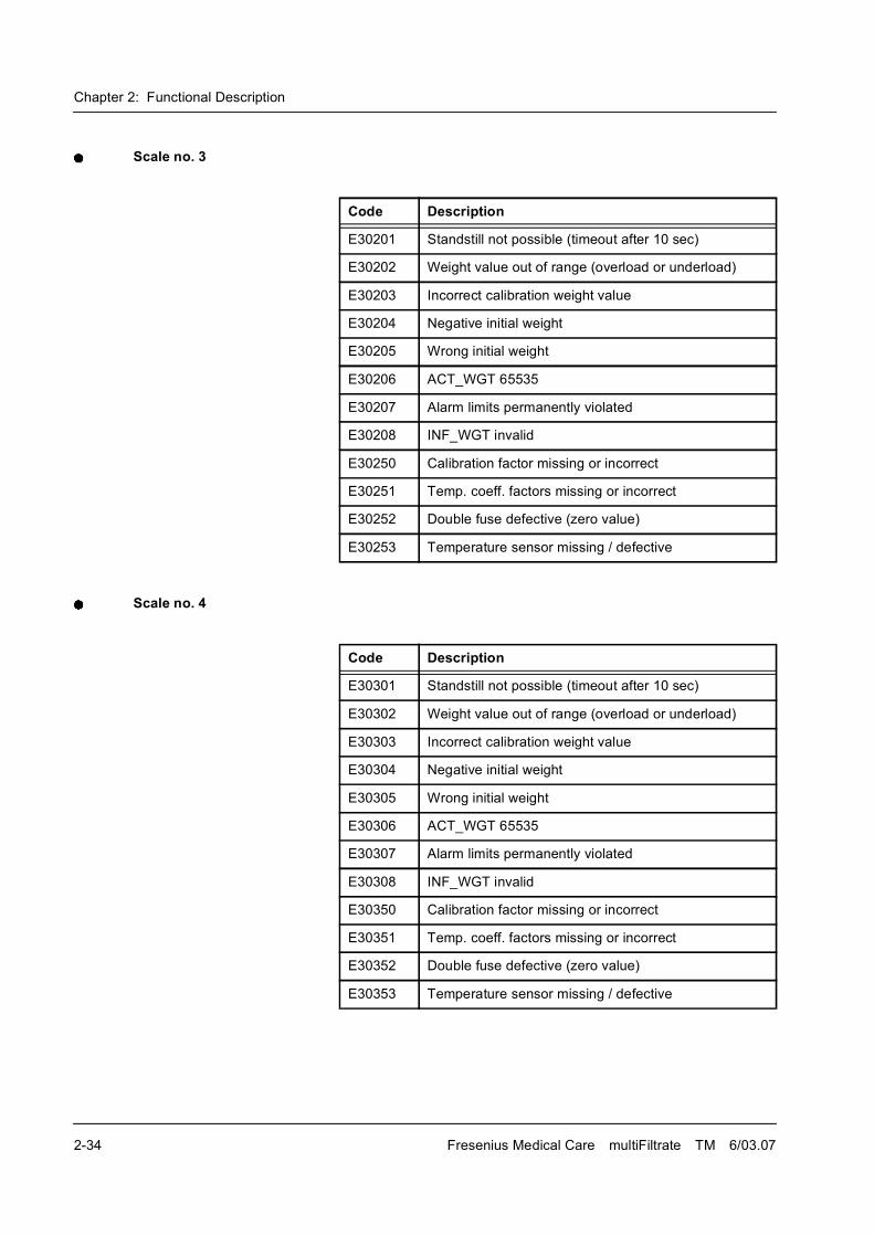
Chapter 2: Functional Description
2-34 Fresenius Medical Care multiFiltrate TM 6/03.07
Scale no. 3
Scale no. 4
Code Description
E30201 Standstill not possible (timeout after 10 sec)
E30202 Weight value out of range (overload or underload)
E30203 Incorrect calibration weight value
E30204 Negative initial weight
E30205 Wrong initial weight
E30206 ACT_WGT 65535
E30207 Alarm limits permanently violated
E30208 INF_WGT invalid
E30250 Calibration factor missing or incorrect
E30251 Temp. coeff. factors missing or incorrect
E30252 Double fuse defective (zero value)
E30253 Temperature sensor missing / defective
Code Description
E30301 Standstill not possible (timeout after 10 sec)
E30302 Weight value out of range (overload or underload)
E30303 Incorrect calibration weight value
E30304 Negative initial weight
E30305 Wrong initial weight
E30306 ACT_WGT 65535
E30307 Alarm limits permanently violated
E30308 INF_WGT invalid
E30350 Calibration factor missing or incorrect
E30351 Temp. coeff. factors missing or incorrect
E30352 Double fuse defective (zero value)
E30353 Temperature sensor missing / defective
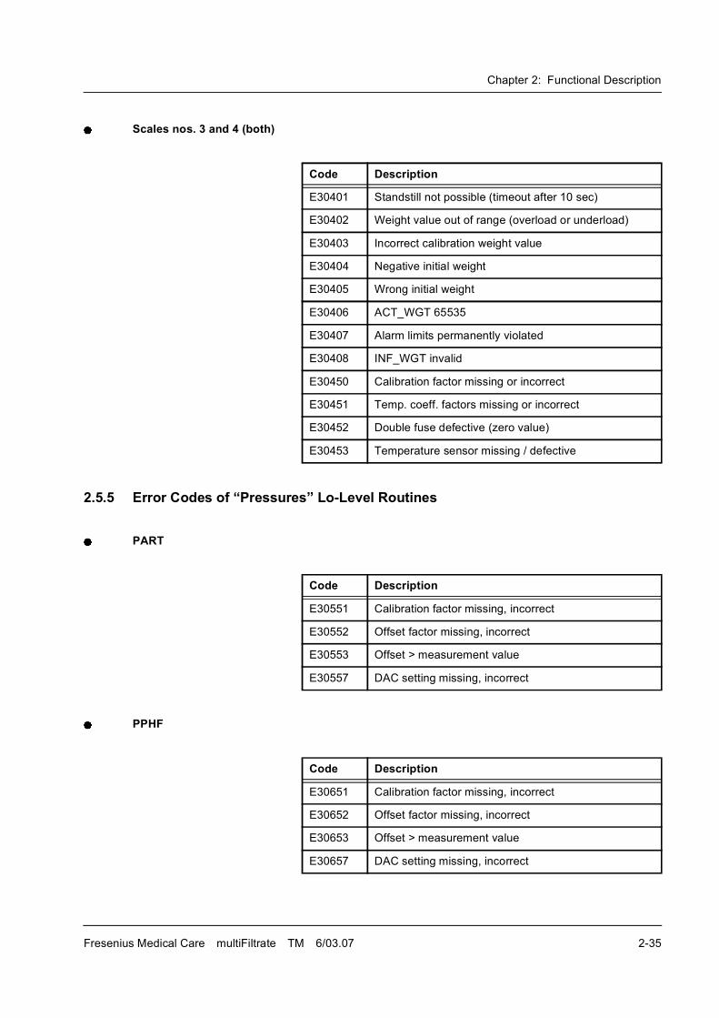
Chapter 2: Functional Description
Fresenius Medical Care multiFiltrate TM 6/03.07 2-35
Scales nos. 3 and 4 (both)
2.5.5 Error Codes of �Pressures� Lo-Level Routines
PART
PPHF
Code Description
E30401 Standstill not possible (timeout after 10 sec)
E30402 Weight value out of range (overload or underload)
E30403 Incorrect calibration weight value
E30404 Negative initial weight
E30405 Wrong initial weight
E30406 ACT_WGT 65535
E30407 Alarm limits permanently violated
E30408 INF_WGT invalid
E30450 Calibration factor missing or incorrect
E30451 Temp. coeff. factors missing or incorrect
E30452 Double fuse defective (zero value)
E30453 Temperature sensor missing / defective
Code Description
E30551 Calibration factor missing, incorrect
E30552 Offset factor missing, incorrect
E30553 Offset > measurement value
E30557 DAC setting missing, incorrect
Code Description
E30651 Calibration factor missing, incorrect
E30652 Offset factor missing, incorrect
E30653 Offset > measurement value
E30657 DAC setting missing, incorrect
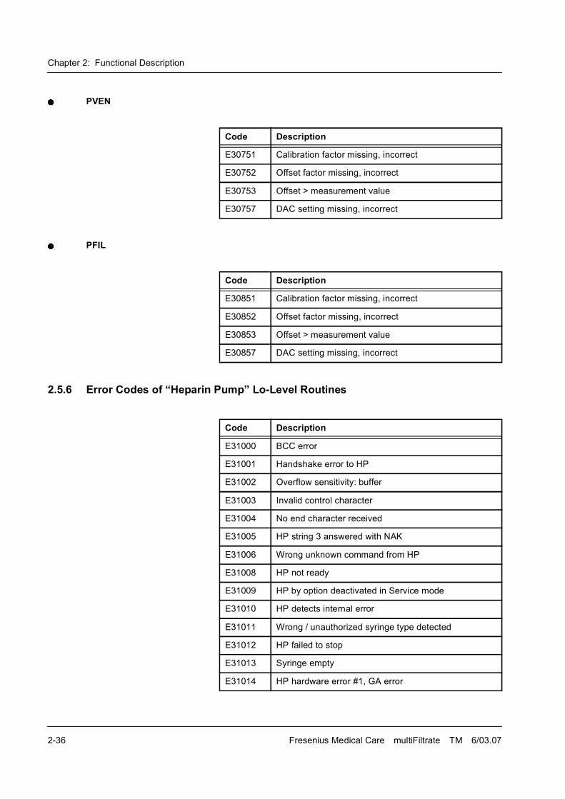
Chapter 2: Functional Description
2-36 Fresenius Medical Care multiFiltrate TM 6/03.07
PVEN
PFIL
2.5.6 Error Codes of �Heparin Pump� Lo-Level Routines
Code Description
E30751 Calibration factor missing, incorrect
E30752 Offset factor missing, incorrect
E30753 Offset > measurement value
E30757 DAC setting missing, incorrect
Code Description
E30851 Calibration factor missing, incorrect
E30852 Offset factor missing, incorrect
E30853 Offset > measurement value
E30857 DAC setting missing, incorrect
Code Description
E31000 BCC error
E31001 Handshake error to HP
E31002 Overflow sensitivity: buffer
E31003 Invalid control character
E31004 No end character received
E31005 HP string 3 answered with NAK
E31006 Wrong unknown command from HP
E31008 HP not ready
E31009 HP by option deactivated in Service mode
E31010 HP detects internal error
E31011 Wrong / unauthorized syringe type detected
E31012 HP failed to stop
E31013 Syringe empty
E31014 HP hardware error #1, GA error
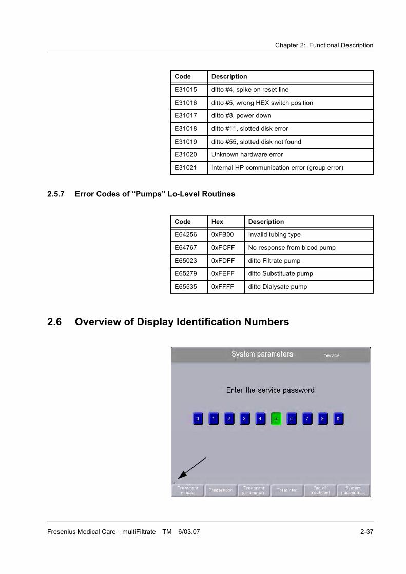
Chapter 2: Functional Description
Fresenius Medical Care multiFiltrate TM 6/03.07 2-37
2.5.7 Error Codes of �Pumps� Lo-Level Routines
2.6 Overview of Display Identification Numbers
E31015 ditto #4, spike on reset line
E31016 ditto #5, wrong HEX switch position
E31017 ditto #8, power down
E31018 ditto #11, slotted disk error
E31019 ditto #55, slotted disk not found
E31020 Unknown hardware error
E31021 Internal HP communication error (group error)
Code Description
Code Hex Description
E64256 0xFB00 Invalid tubing type
E64767 0xFCFF No response from blood pump
E65023 0xFDFF ditto Filtrate pump
E65279 0xFEFF ditto Substituate pump
E65535 0xFFFF ditto Dialysate pump
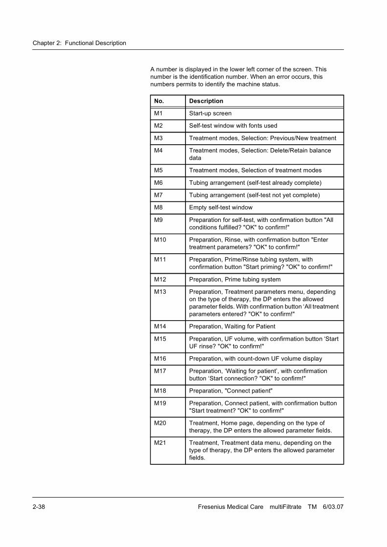
Chapter 2: Functional Description
2-38 Fresenius Medical Care multiFiltrate TM 6/03.07
A number is displayed in the lower left corner of the screen. This
number is the identification number. When an error occurs, this
numbers permits to identify the machine status.
No. Description
M1 Start-up screen
M2 Self-test window with fonts used
M3 Treatment modes, Selection: Previous/New treatment
M4 Treatment modes, Selection: Delete/Retain balance
data
M5 Treatment modes, Selection of treatment modes
M6 Tubing arrangement (self-test already complete)
M7 Tubing arrangement (self-test not yet complete)
M8 Empty self-test window
M9 Preparation for self-test, with confirmation button "All
conditions fulfilled? "OK" to confirm!"
M10 Preparation, Rinse, with confirmation button "Enter
treatment parameters? "OK" to confirm!"
M11 Preparation, Prime/Rinse tubing system, with
confirmation button "Start priming? "OK" to confirm!"
M12 Preparation, Prime tubing system
M13 Preparation, Treatment parameters menu, depending
on the type of therapy, the DP enters the allowed
parameter fields. With confirmation button �All treatment
parameters entered? "OK" to confirm!"
M14 Preparation, Waiting for Patient
M15 Preparation, UF volume, with confirmation button �Start
UF rinse? "OK" to confirm!"
M16 Preparation, with count-down UF volume display
M17 Preparation, �Waiting for patient�, with confirmation
button �Start connection? "OK" to confirm!"
M18 Preparation, "Connect patient"
M19 Preparation, Connect patient, with confirmation button
"Start treatment? "OK" to confirm!"
M20 Treatment, Home page, depending on the type of
therapy, the DP enters the allowed parameter fields.
M21 Treatment, Treatment data menu, depending on the
type of therapy, the DP enters the allowed parameter
fields.
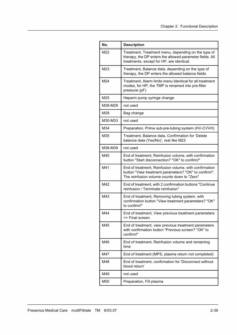
Chapter 2: Functional Description
Fresenius Medical Care multiFiltrate TM 6/03.07 2-39
M22 Treatment, Treatment menu, depending on the type of
therapy, the DP enters the allowed parameter fields. All
treatments, except for HP, are identical.
M23 Treatment, Balance data, depending on the type of
therapy, the DP enters the allowed balance fields.
M24 Treatment, Alarm limits menu Identical for all treatment
modes, for HP, the TMP is renamed into pre-filter
pressure (pF)
M25 Heparin pump syringe change
M26-M28 not used
M29 Bag change
M30-M33 not used
M34 Preparation, Prime sub-pre-tubing system (HV-CVVH)
M35 Treatment, Balance data, Confirmation for �Delete
balance data (Yes/No)�, rest like M23
M36-M39 not used
M40 End of treatment, Reinfusion volume, with confirmation
button "Start disconnection? "OK" to confirm!"
M41 End of treatment, Reinfusion volume, with confirmation
button "View treatment parameters? "OK" to confirm!".
The reinfusion volume counts down to "Zero"
M42 End of treatment, with 2 confirmation buttons "Continue
reinfusion / Terminate reinfusion"
M43 End of treatment, Removing tubing system, with
confirmation button "View treatment parameters? "OK"
to confirm!"
M44 End of treatment, View previous treatment parameters
=> Final screen.
M45 End of treatment, view previous treatment parameters
with confirmation button "Previous screen? "OK" to
confirm!"
M46 End of treatment, Reinfusion volume and remaining
time
M47 End of treatment (MPS, plasma return not completed)
M48 End of treatment, confirmation for 'Disconnect without
blood return'
M49 not used
M50 Preparation, Fill plasma
No. Description
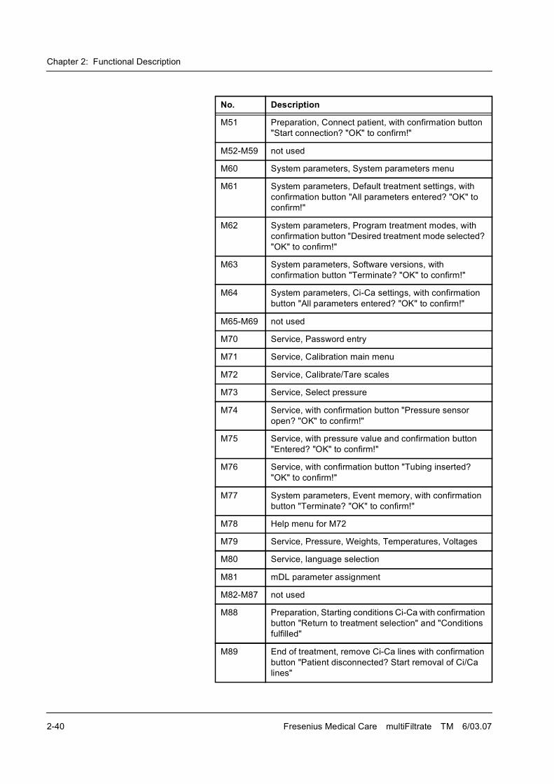
Chapter 2: Functional Description
2-40 Fresenius Medical Care multiFiltrate TM 6/03.07
M51 Preparation, Connect patient, with confirmation button
"Start connection? "OK" to confirm!"
M52-M59 not used
M60 System parameters, System parameters menu
M61 System parameters, Default treatment settings, with
confirmation button "All parameters entered? "OK" to
confirm!"
M62 System parameters, Program treatment modes, with
confirmation button "Desired treatment mode selected?
"OK" to confirm!"
M63 System parameters, Software versions, with
confirmation button "Terminate? "OK" to confirm!"
M64 System parameters, Ci-Ca settings, with confirmation
button "All parameters entered? "OK" to confirm!"
M65-M69 not used
M70 Service, Password entry
M71 Service, Calibration main menu
M72 Service, Calibrate/Tare scales
M73 Service, Select pressure
M74 Service, with confirmation button "Pressure sensor
open? "OK" to confirm!"
M75 Service, with pressure value and confirmation button
"Entered? "OK" to confirm!"
M76 Service, with confirmation button "Tubing inserted?
"OK" to confirm!"
M77 System parameters, Event memory, with confirmation
button "Terminate? "OK" to confirm!"
M78 Help menu for M72
M79 Service, Pressure, Weights, Temperatures, Voltages
M80 Service, language selection
M81 mDL parameter assignment
M82-M87 not used
M88 Preparation, Starting conditions Ci-Ca with confirmation
button "Return to treatment selection" and "Conditions
fulfilled"
M89 End of treatment, remove Ci-Ca lines with confirmation
button "Patient disconnected? Start removal of Ci/Ca
lines"
No. Description
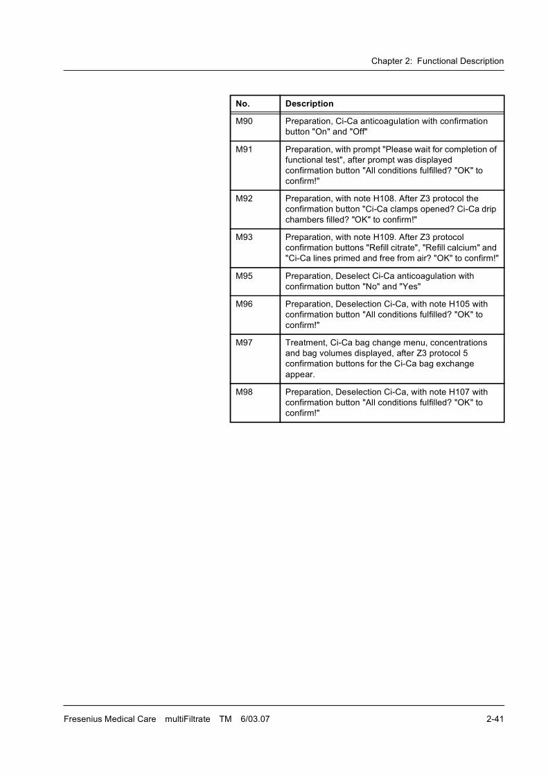
Chapter 2: Functional Description
Fresenius Medical Care multiFiltrate TM 6/03.07 2-41
M90 Preparation, Ci-Ca anticoagulation with confirmation
button "On" and "Off"
M91 Preparation, with prompt "Please wait for completion of
functional test", after prompt was displayed
confirmation button "All conditions fulfilled? "OK" to
confirm!"
M92 Preparation, with note H108. After Z3 protocol the
confirmation button "Ci-Ca clamps opened? Ci-Ca drip
chambers filled? "OK" to confirm!"
M93 Preparation, with note H109. After Z3 protocol
confirmation buttons "Refill citrate", "Refill calcium" and
"Ci-Ca lines primed and free from air? "OK" to confirm!"
M95 Preparation, Deselect Ci-Ca anticoagulation with
confirmation button "No" and "Yes"
M96 Preparation, Deselection Ci-Ca, with note H105 with
confirmation button "All conditions fulfilled? "OK" to
confirm!"
M97 Treatment, Ci-Ca bag change menu, concentrations
and bag volumes displayed, after Z3 protocol 5
confirmation buttons for the Ci-Ca bag exchange
appear.
M98 Preparation, Deselection Ci-Ca, with note H107 with
confirmation button "All conditions fulfilled? "OK" to
confirm!"
No. Description

Chapter 2: Functional Description
2-42 Fresenius Medical Care multiFiltrate TM 6/03.07
Chapter 3: Installation
Fresenius Medical Care multiFiltrate TM 6/03.07 3-1
3 Installation
3.1 Preface
Instructions for all technicians who are authorized to commission our systems.
We, as manufacturers, permanently aim at delivering systems of
highest quality.
To reach this aim, we need your support.
Please commission our systems uniformly using the enclosed "initial
start-up report" and enter the values determined in the columns
provided.
The following is applicable:Corrections are necessary only if the measured values are outside of the specified tolerances!
We will then evaluate the initial start-up reports, which will enable us to
monitor the quality of our systems on their delivery.
After initial start-up, please asap send � by mail or by fax � the
completed form (Initial Start-Up Report) back to the following address:
Thank you very much for your help!
ServiceCentral Europe
Fresenius Medical Care
Deutschland GmbH
Geschäftsbereich Zentraleuropa
Kundendienst / Servicecenter
Steinmühlstraße 24
61352 Bad Homburg
Germany
Phone: +49 6172 609-7100
Fax: +49 6172 609-7102
E-mail: [email protected]
Internationalservice
Responsible Regional Organization
(Technical Service)
Chapter 3: Installation
3-2 Fresenius Medical Care multiFiltrate TM 6/03.07
3.2 Important Information on Initial Start-Up
For initial start-up only This technical document is intended for initial start-up only. It is not
intended for restarting systems that have been shut down or have been
put out of service temporarily.
Tester's qualification The initial start-up must be performed by the Technical Service of
Fresenius Medical Care or a person authorized by them.
The initial start-up procedure may only be performed by persons who
are qualified to properly perform the specified checks owing to their
educational background and training, their knowledge and experience
gained in practice. Furthermore, the persons performing the tests must
not be bound by any directives when performing this activity.
Test equipment and accessories
The activities described in this technical document require the
availability of the necessary technical test equipment and accessories.
Any information on the specifications must be observed.
Environmental conditions Variations in temperature during transport may lead to condensation
water developing on live parts. In the event of major variations in
temperature, allow sufficient time for the system to adjust to the ambient
temperature before start-up.
TSC/TMC/MA intervals The TSC/TMC/MA procedures for this system are to be performed after
12 months.
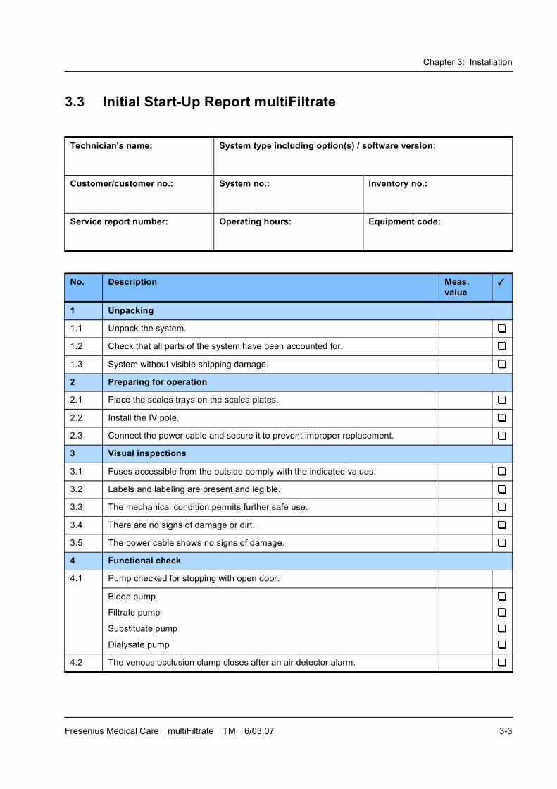
Chapter 3: Installation
Fresenius Medical Care multiFiltrate TM 6/03.07 3-3
3.3 Initial Start-Up Report multiFiltrate
Technician's name: System type including option(s) / software version:
Customer/customer no.: System no.: Inventory no.:
Service report number: Operating hours: Equipment code:
No. Description Meas. value
1 Unpacking
1.1 Unpack the system.
1.2 Check that all parts of the system have been accounted for.
1.3 System without visible shipping damage.
2 Preparing for operation
2.1 Place the scales trays on the scales plates.
2.2 Install the IV pole.
2.3 Connect the power cable and secure it to prevent improper replacement.
3 Visual inspections
3.1 Fuses accessible from the outside comply with the indicated values.
3.2 Labels and labeling are present and legible.
3.3 The mechanical condition permits further safe use.
3.4 There are no signs of damage or dirt.
3.5 The power cable shows no signs of damage.
4 Functional check
4.1 Pump checked for stopping with open door.
Blood pump
Filtrate pump
Substituate pump
Dialysate pump
4.2 The venous occlusion clamp closes after an air detector alarm.
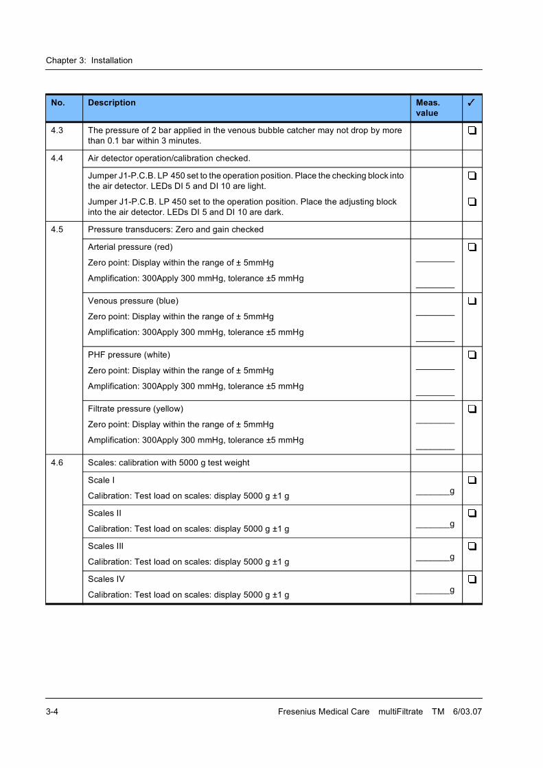
Chapter 3: Installation
3-4 Fresenius Medical Care multiFiltrate TM 6/03.07
4.3 The pressure of 2 bar applied in the venous bubble catcher may not drop by more
than 0.1 bar within 3 minutes.
4.4 Air detector operation/calibration checked.
Jumper J1-P.C.B. LP 450 set to the operation position. Place the checking block into
the air detector. LEDs DI 5 and DI 10 are light.
Jumper J1-P.C.B. LP 450 set to the operation position. Place the adjusting block
into the air detector. LEDs DI 5 and DI 10 are dark.
4.5 Pressure transducers: Zero and gain checked
Arterial pressure (red)
Zero point: Display within the range of ± 5mmHg
Amplification: 300Apply 300 mmHg, tolerance ±5 mmHg
________
________
Venous pressure (blue)
Zero point: Display within the range of ± 5mmHg
Amplification: 300Apply 300 mmHg, tolerance ±5 mmHg
________
________
PHF pressure (white)
Zero point: Display within the range of ± 5mmHg
Amplification: 300Apply 300 mmHg, tolerance ±5 mmHg
________
________
Filtrate pressure (yellow)
Zero point: Display within the range of ± 5mmHg
Amplification: 300Apply 300 mmHg, tolerance ±5 mmHg
________
________
4.6 Scales: calibration with 5000 g test weight
Scale I
Calibration: Test load on scales: display 5000 g ±1 g_______g
Scales II
Calibration: Test load on scales: display 5000 g ±1 g_______g
Scales III
Calibration: Test load on scales: display 5000 g ±1 g_______g
Scales IV
Calibration: Test load on scales: display 5000 g ±1 g_______g
No. Description Meas. value
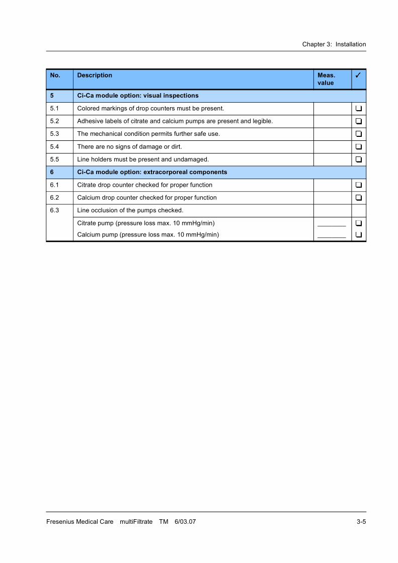
Chapter 3: Installation
Fresenius Medical Care multiFiltrate TM 6/03.07 3-5
5 Ci-Ca module option: visual inspections
5.1 Colored markings of drop counters must be present.
5.2 Adhesive labels of citrate and calcium pumps are present and legible.
5.3 The mechanical condition permits further safe use.
5.4 There are no signs of damage or dirt.
5.5 Line holders must be present and undamaged.
6 Ci-Ca module option: extracorporeal components
6.1 Citrate drop counter checked for proper function
6.2 Calcium drop counter checked for proper function
6.3 Line occlusion of the pumps checked.
Citrate pump (pressure loss max. 10 mmHg/min)
Calcium pump (pressure loss max. 10 mmHg/min)
________
________
No. Description Meas. value
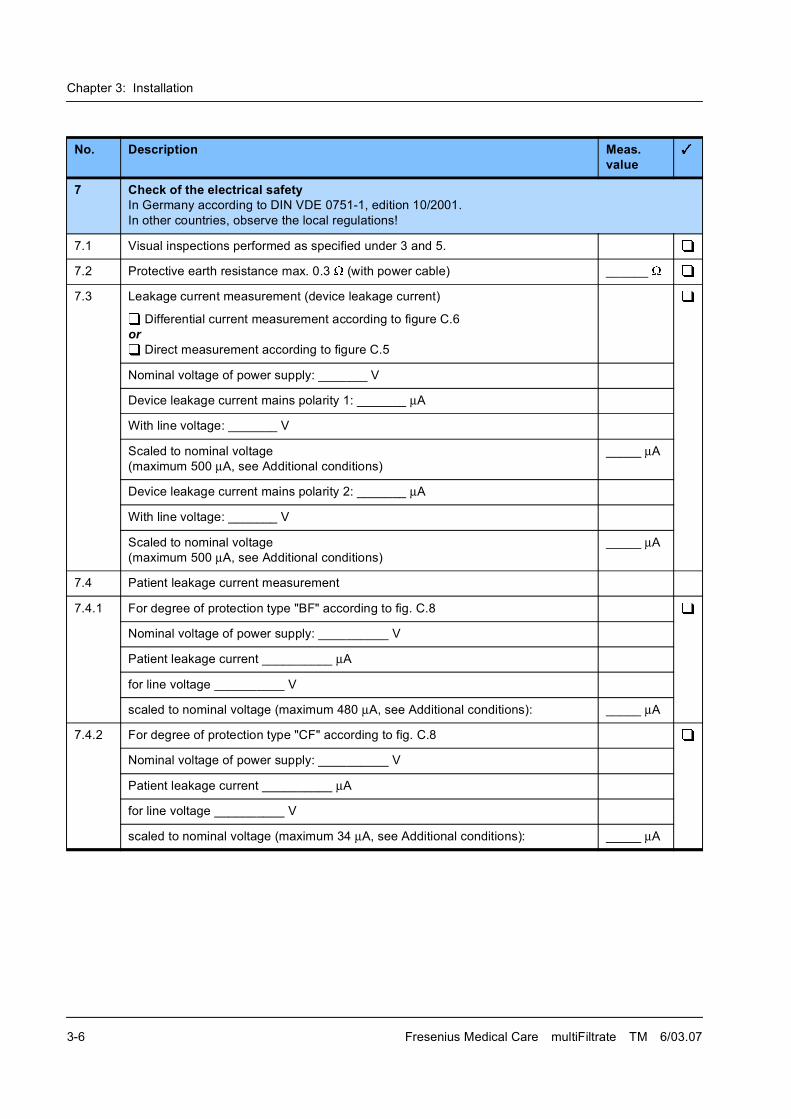
Chapter 3: Installation
3-6 Fresenius Medical Care multiFiltrate TM 6/03.07
7 Check of the electrical safety In Germany according to DIN VDE 0751-1, edition 10/2001.
In other countries, observe the local regulations!
7.1 Visual inspections performed as specified under 3 and 5.
7.2 Protective earth resistance max. 0.3 (with power cable) ______
7.3 Leakage current measurement (device leakage current)
Differential current measurement according to figure C.6
or
Direct measurement according to figure C.5
Nominal voltage of power supply: _______ V
Device leakage current mains polarity 1: _______ �A
With line voltage: _______ V
Scaled to nominal voltage
(maximum 500 �A, see Additional conditions)
_____ �A
Device leakage current mains polarity 2: _______ �A
With line voltage: _______ V
Scaled to nominal voltage
(maximum 500 �A, see Additional conditions)
_____ �A
7.4 Patient leakage current measurement
7.4.1 For degree of protection type "BF" according to fig. C.8
Nominal voltage of power supply: __________ V
Patient leakage current __________ �A
for line voltage __________ V
scaled to nominal voltage (maximum 480 �A, see Additional conditions): _____ �A
7.4.2 For degree of protection type "CF" according to fig. C.8
Nominal voltage of power supply: __________ V
Patient leakage current __________ �A
for line voltage __________ V
scaled to nominal voltage (maximum 34 �A, see Additional conditions): _____ �A
No. Description Meas. value
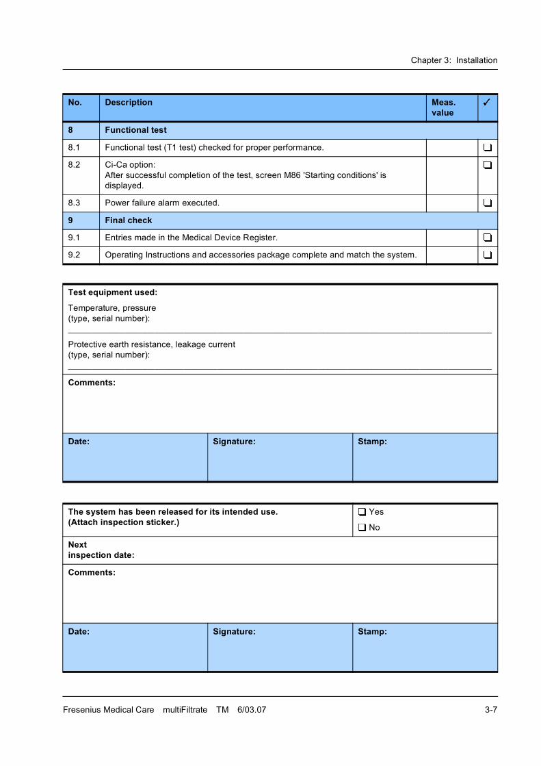
Chapter 3: Installation
Fresenius Medical Care multiFiltrate TM 6/03.07 3-7
8 Functional test
8.1 Functional test (T1 test) checked for proper performance.
8.2 Ci-Ca option:
After successful completion of the test, screen M86 'Starting conditions' is
displayed.
8.3 Power failure alarm executed.
9 Final check
9.1 Entries made in the Medical Device Register.
9.2 Operating Instructions and accessories package complete and match the system.
Test equipment used:
Temperature, pressure
(type, serial number):
________________________________________________________________________________________
Protective earth resistance, leakage current
(type, serial number):
________________________________________________________________________________________
Comments:
Date: Signature: Stamp:
The system has been released for its intended use.(Attach inspection sticker.)
Yes
No
Nextinspection date:
Comments:
Date: Signature: Stamp:
No. Description Meas. value
Chapter 3: Installation
3-8 Fresenius Medical Care multiFiltrate TM 6/03.07
3.4 Explanations on the Initial Start-Up Report
Identification
Technician's name:Technician's first name and surname.
Customer/customer no.:Number of the final customer.
Service report number:Number of the service call.
System type including option(s):System name with possible options and extras.
System no.:Serial number indicated on the type label.
Inventory no.:Inventory number assigned to the system.
Operating hours:Operating hours, if a time meter is installed.
Equipment code:Equipment code indicated on the system.
(e.g. EC xxx, E-code xxx)
Re: 1.1
Remove the system from its transport packaging and save the
packaging for possible future return shipments.
Re: 1.2
Check that all parts of the system have been accounted for. Inform your
contact at Fresenius immediately of any missing parts.
Re: 4 - Functional check
For detailed information refer to chapter 5 "Adjustment Instructions and
Tests"
Re: 5 - Check of the electrical safety
In Germany according to DIN VDE 0751-1, edition 10/2001.
In other countries, observe the local regulations!
(Use DIN VDE 0751-1, edition 10/2001, for medical products. Use DIN
VDE 0701-1 for electrical production equipment.)
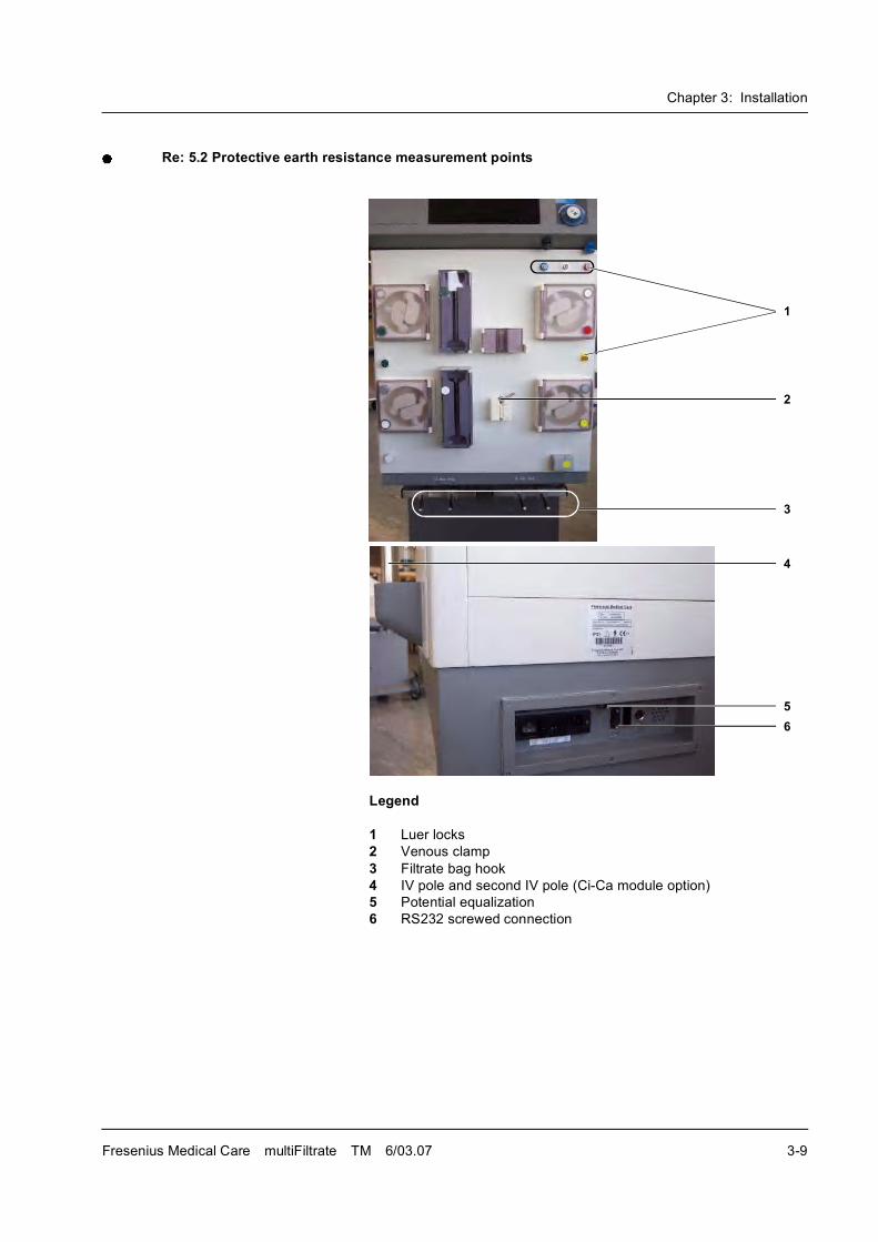
Chapter 3: Installation
Fresenius Medical Care multiFiltrate TM 6/03.07 3-9
Re: 5.2 Protective earth resistance measurement points
Legend
1 Luer locks
2 Venous clamp
3 Filtrate bag hook
4 IV pole and second IV pole (Ci-Ca module option)
5 Potential equalization
6 RS232 screwed connection
1
2
3
4
5
6

Chapter 3: Installation
3-10 Fresenius Medical Care multiFiltrate TM 6/03.07
Re: 5.3 Leakage current measurement (device leakage current)
Fig.: Differential current measurement according to fig. C.6
Fig.: Direct measurement according to fig. C.5
Basic requirements:
� Measurement of the protective earth resistance performed.
� The system is in standby operating mode (system connected to the
mains).
� The same measurement kit (M28 060 1) as for the patient leakage
current measurement is used for the measurement. Place the
measuring plates on both bag trays and insert the heater bags filled
with NaCl. Measurement setup, see appendix.
� When performing a direct measurement, the following precautions
also must be observed:
The system must be insulated when installed. All external
connections and the potential equalization must have been removed
from the system.
Chapter 3: Installation
Fresenius Medical Care multiFiltrate TM 6/03.07 3-11
Documentation covers the nominal voltage during the measurement
and the device leakage current at line voltage, scaled to the nominal line
voltage.Example:
Line voltage during measurement: 225 V
Device leakage current
for mains polarity 1: 38 µA
for mains polarity 2: 57 µA
Maximum value of both mains polarities: 57 µA
Nominal voltage of the power supply: 230 V
Scaled to nominal voltage: 58 µA
(58 µA: 225 V � 230 V = 58 µA)
Device leakage current < 500 µA: OK
Additional conditions:
If the device leakage current is higher than 90 % of the admissible alarm
limit (450 µA), the last measured value or the first measured value must
additionally be considered for the rating.
If the device leakage current considerably increased since the last
measurement or continuously increased since the first measurement
(creeping deterioration of the insulation), or if the sum composed of the
current value plus the difference since the last measurement is
> 500 µA, the measurement has not been passed.Example 1:
Leakage current: 470 µA
Last measured value: 450 A
470 + (470 � 450) = 470 + 20 = 490
OK
Example 2:
Leakage current: 470 µA
Last measured value: 390 µA
470 + (470 � 390) = 470 + 80 = 550
Not passed
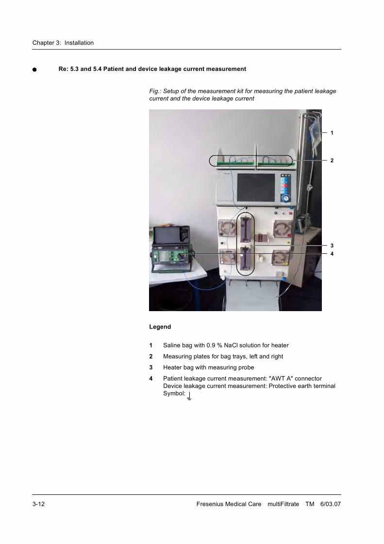
Chapter 3: Installation
3-12 Fresenius Medical Care multiFiltrate TM 6/03.07
Re: 5.3 and 5.4 Patient and device leakage current measurement
Fig.: Setup of the measurement kit for measuring the patient leakage
current and the device leakage current
Legend
1 Saline bag with 0.9 % NaCl solution for heater
2 Measuring plates for bag trays, left and right
3 Heater bag with measuring probe
4 Patient leakage current measurement: "AWT A" connector
Device leakage current measurement: Protective earth terminal
Symbol:
1
2
3
4
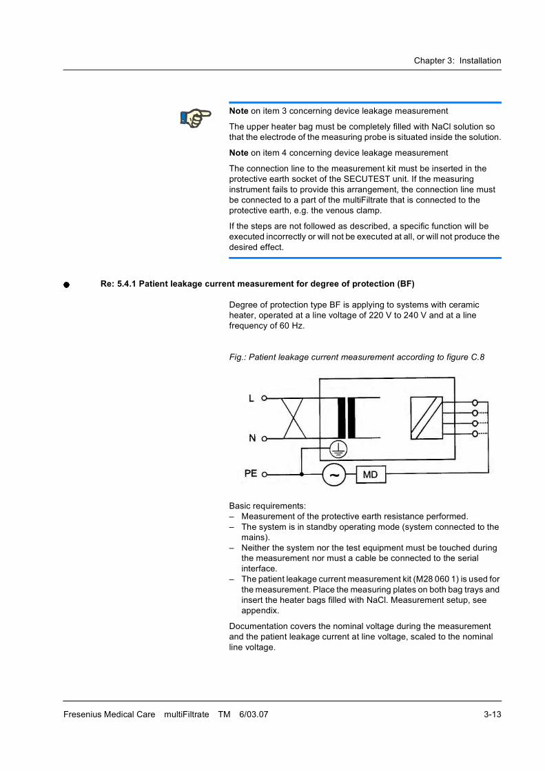
Chapter 3: Installation
Fresenius Medical Care multiFiltrate TM 6/03.07 3-13
Re: 5.4.1 Patient leakage current measurement for degree of protection (BF)
Degree of protection type BF is applying to systems with ceramic
heater, operated at a line voltage of 220 V to 240 V and at a line
frequency of 60 Hz.
Fig.: Patient leakage current measurement according to figure C.8
Basic requirements:
� Measurement of the protective earth resistance performed.
� The system is in standby operating mode (system connected to the
mains).
� Neither the system nor the test equipment must be touched during
the measurement nor must a cable be connected to the serial
interface.
� The patient leakage current measurement kit (M28 060 1) is used for
the measurement. Place the measuring plates on both bag trays and
insert the heater bags filled with NaCl. Measurement setup, see
appendix.
Documentation covers the nominal voltage during the measurement
and the patient leakage current at line voltage, scaled to the nominal
line voltage.
Note on item 3 concerning device leakage measurement
The upper heater bag must be completely filled with NaCl solution so
that the electrode of the measuring probe is situated inside the solution.
Note on item 4 concerning device leakage measurement
The connection line to the measurement kit must be inserted in the
protective earth socket of the SECUTEST unit. If the measuring
instrument fails to provide this arrangement, the connection line must
be connected to a part of the multiFiltrate that is connected to the
protective earth, e.g. the venous clamp.
If the steps are not followed as described, a specific function will be
executed incorrectly or will not be executed at all, or will not produce the
desired effect.
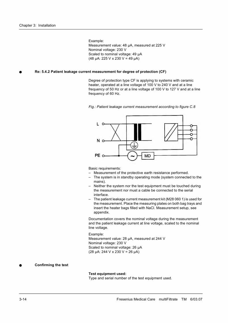
Chapter 3: Installation
3-14 Fresenius Medical Care multiFiltrate TM 6/03.07
Example:
Measurement value: 48 µA, measured at 225 V
Nominal voltage: 230 V
Scaled to nominal voltage: 49 µA
(48 µA: 225 V x 230 V = 49 µA)
Re: 5.4.2 Patient leakage current measurement for degree of protection (CF)
Degree of protection type CF is applying to systems with ceramic
heater, operated at a line voltage of 100 V to 240 V and at a line
frequency of 50 Hz or at a line voltage of 100 V to 127 V and at a line
frequency of 60 Hz.
Fig.: Patient leakage current measurement according to figure C.8
Basic requirements:
� Measurement of the protective earth resistance performed.
� The system is in standby operating mode (system connected to the
mains).
� Neither the system nor the test equipment must be touched during
the measurement nor must a cable be connected to the serial
interface.
� The patient leakage current measurement kit (M28 060 1) is used for
the measurement. Place the measuring plates on both bag trays and
insert the heater bags filled with NaCl. Measurement setup, see
appendix.
Documentation covers the nominal voltage during the measurement
and the patient leakage current at line voltage, scaled to the nominal
line voltage.
Example:
Measurement value: 28 µA, measured at 244 V
Nominal voltage: 230 V
Scaled to nominal voltage: 26 µA
(28 µA: 244 V x 230 V = 26 µA)
Confirming the test
Test equipment used:Type and serial number of the test equipment used.
Chapter 3: Installation
Fresenius Medical Care multiFiltrate TM 6/03.07 3-15
Comments:Irregularities encountered during the test will be recorded in this section.
Date, signature, stampPerformance of the test has to be confirmed by indicating date, tester's
signature and stamp.
Assessing the test
The system has been released for its intended use.(Attach inspection sticker.)
During the intended use of the system it must be ensured that the
system does not present a hazard to patients, employees or other third
parties.
Within the scope of the overall assessment, the tester must make a
definite decision whether the system may be used or not. The
responsible organization must immediately be informed of any defects
detected.
Next inspection date:The next inspection date has to be entered in the report.
The intervals specified by the manufacturer have to be respected!
Comments:Irregularities encountered during the assessment will be recorded in
this section.
Date, signature, stamp:Assessment of the initial start-up has to be confirmed by indicating date,
tester's signature and stamp.
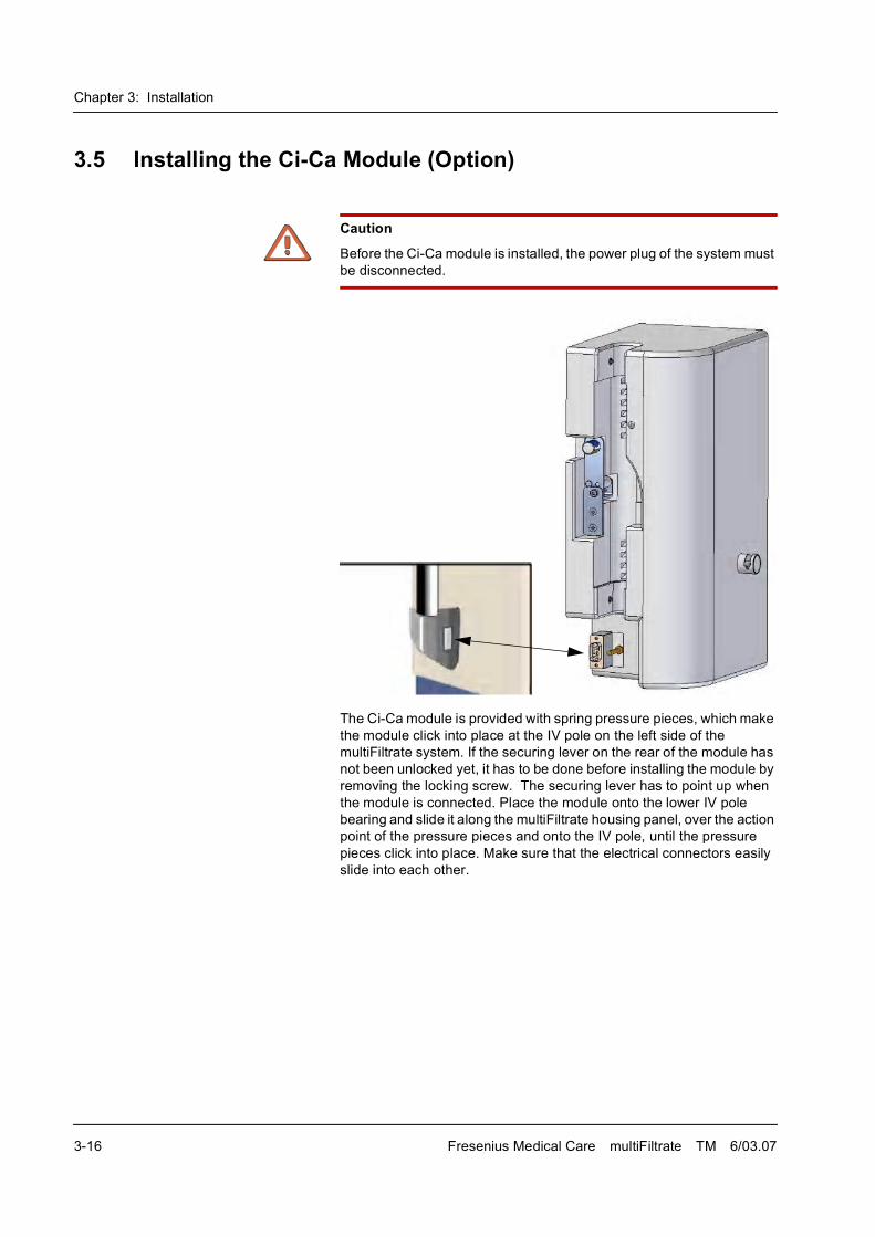
Chapter 3: Installation
3-16 Fresenius Medical Care multiFiltrate TM 6/03.07
3.5 Installing the Ci-Ca Module (Option)
The Ci-Ca module is provided with spring pressure pieces, which make
the module click into place at the IV pole on the left side of the
multiFiltrate system. If the securing lever on the rear of the module has
not been unlocked yet, it has to be done before installing the module by
removing the locking screw. The securing lever has to point up when
the module is connected. Place the module onto the lower IV pole
bearing and slide it along the multiFiltrate housing panel, over the action
point of the pressure pieces and onto the IV pole, until the pressure
pieces click into place. Make sure that the electrical connectors easily
slide into each other.
Caution
Before the Ci-Ca module is installed, the power plug of the system must
be disconnected.
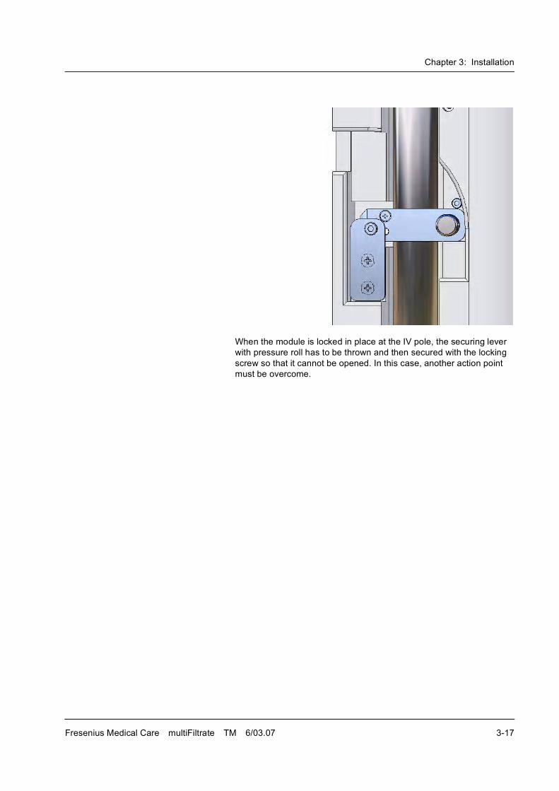
Chapter 3: Installation
Fresenius Medical Care multiFiltrate TM 6/03.07 3-17
When the module is locked in place at the IV pole, the securing lever
with pressure roll has to be thrown and then secured with the locking
screw so that it cannot be opened. In this case, another action point
must be overcome.

Chapter 3: Installation
3-18 Fresenius Medical Care multiFiltrate TM 6/03.07
Chapter 4: TSC / TMC / Maintenance
Fresenius Medical Care multiFiltrate TM 6/03.07 4-1
4 TSC / TMC / Maintenance
4.1 Important Information Regarding the Procedure
Tester's qualification The initial start-up must be performed by the Technical Service of
Fresenius Medical Care or a person authorized by them!
The tests may only be performed by persons who are qualified to
properly perform the specified checks owing to their educational
background and training, their knowledge and experience gained in
practice. Furthermore, the persons performing the tests must not be
bound by any directives when performing this activity.
Test equipment and accessories
The activities described in this technical document require the
availability of the necessary technical test equipment and accessories.
Any information on the specifications must be observed.
TSC/TMC/MA intervals The TSC/TMC/MA procedures for this system are to be performed after
12 months.
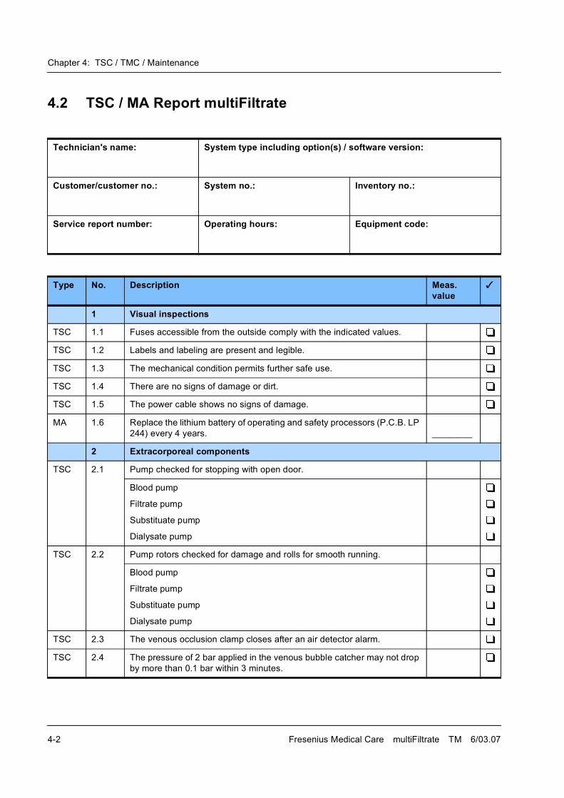
Chapter 4: TSC / TMC / Maintenance
4-2 Fresenius Medical Care multiFiltrate TM 6/03.07
4.2 TSC / MA Report multiFiltrate
Technician's name: System type including option(s) / software version:
Customer/customer no.: System no.: Inventory no.:
Service report number: Operating hours: Equipment code:
Type No. Description Meas. value
1 Visual inspections
TSC 1.1 Fuses accessible from the outside comply with the indicated values.
TSC 1.2 Labels and labeling are present and legible.
TSC 1.3 The mechanical condition permits further safe use.
TSC 1.4 There are no signs of damage or dirt.
TSC 1.5 The power cable shows no signs of damage.
MA 1.6 Replace the lithium battery of operating and safety processors (P.C.B. LP
244) every 4 years. ________
2 Extracorporeal components
TSC 2.1 Pump checked for stopping with open door.
Blood pump
Filtrate pump
Substituate pump
Dialysate pump
TSC 2.2 Pump rotors checked for damage and rolls for smooth running.
Blood pump
Filtrate pump
Substituate pump
Dialysate pump
TSC 2.3 The venous occlusion clamp closes after an air detector alarm.
TSC 2.4 The pressure of 2 bar applied in the venous bubble catcher may not drop
by more than 0.1 bar within 3 minutes.
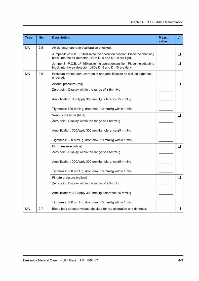
Chapter 4: TSC / TMC / Maintenance
Fresenius Medical Care multiFiltrate TM 6/03.07 4-3
MA 2.5 Air detector operation/calibration checked.
Jumper J1-P.C.B. LP 450 set to the operation position. Place the checking
block into the air detector. LEDs DI 5 and DI 10 are light.
Jumper J1-P.C.B. LP 450 set to the operation position. Place the adjusting
block into the air detector. LEDs DI 5 and DI 10 are dark.
MA 2.6 Pressure transducers: zero point and amplification as well as tightness
checked.
Arterial pressure (red)
Zero point: Display within the range of ± 5mmHg
Amplification: 300Apply 300 mmHg, tolerance ±5 mmHg
Tightness: 600 mmHg, drop max. 10 mmHg within 1 min
________
________
________
Venous pressure (blue)
Zero point: Display within the range of ± 5mmHg
Amplification: 300Apply 300 mmHg, tolerance ±5 mmHg
Tightness: 600 mmHg, drop max. 10 mmHg within 1 min
________
________
________
PHF pressure (white)
Zero point: Display within the range of ± 5mmHg
Amplification: 300Apply 300 mmHg, tolerance ±5 mmHg
Tightness: 600 mmHg, drop max. 10 mmHg within 1 min
________
________
________
Filtrate pressure (yellow)
Zero point: Display within the range of ± 5mmHg
Amplification: 300Apply 300 mmHg, tolerance ±5 mmHg
Tightness: 600 mmHg, drop max. 10 mmHg within 1 min
________
________
________
MA 2.7 Blood leak detector values checked for red coloration and dimness.
Type No. Description Meas. value
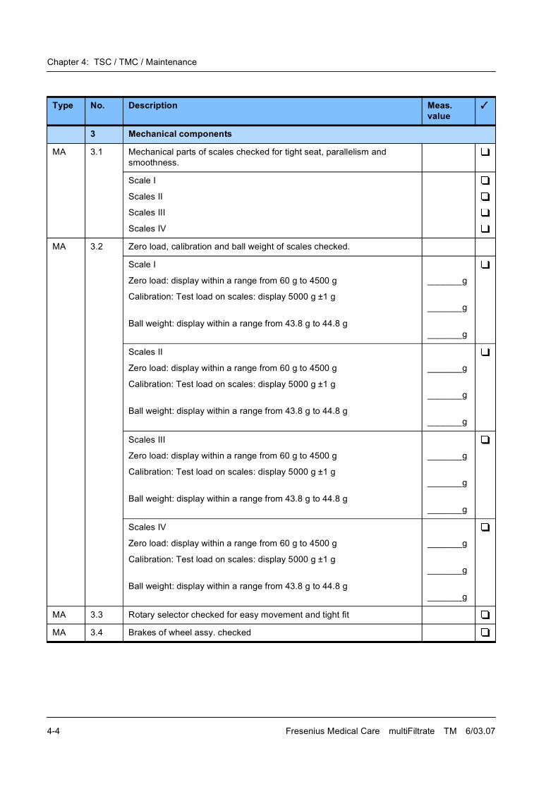
Chapter 4: TSC / TMC / Maintenance
4-4 Fresenius Medical Care multiFiltrate TM 6/03.07
3 Mechanical components
MA 3.1 Mechanical parts of scales checked for tight seat, parallelism and
smoothness.
Scale I
Scales II
Scales III
Scales IV
MA 3.2 Zero load, calibration and ball weight of scales checked.
Scale I
Zero load: display within a range from 60 g to 4500 g
Calibration: Test load on scales: display 5000 g ±1 g
Ball weight: display within a range from 43.8 g to 44.8 g
_______g
_______g
_______g
Scales II
Zero load: display within a range from 60 g to 4500 g
Calibration: Test load on scales: display 5000 g ±1 g
Ball weight: display within a range from 43.8 g to 44.8 g
_______g
_______g
_______g
Scales III
Zero load: display within a range from 60 g to 4500 g
Calibration: Test load on scales: display 5000 g ±1 g
Ball weight: display within a range from 43.8 g to 44.8 g
_______g
_______g
_______g
Scales IV
Zero load: display within a range from 60 g to 4500 g
Calibration: Test load on scales: display 5000 g ±1 g
Ball weight: display within a range from 43.8 g to 44.8 g
_______g
_______g
_______g
MA 3.3 Rotary selector checked for easy movement and tight fit
MA 3.4 Brakes of wheel assy. checked
Type No. Description Meas. value
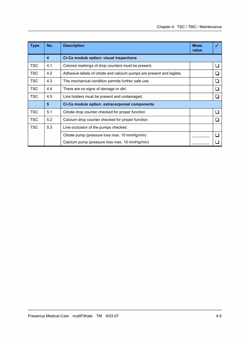
Chapter 4: TSC / TMC / Maintenance
Fresenius Medical Care multiFiltrate TM 6/03.07 4-5
4 Ci-Ca module option: visual inspections
TSC 4.1 Colored markings of drop counters must be present.
TSC 4.2 Adhesive labels of citrate and calcium pumps are present and legible.
TSC 4.3 The mechanical condition permits further safe use.
TSC 4.4 There are no signs of damage or dirt.
TSC 4.5 Line holders must be present and undamaged.
5 Ci-Ca module option: extracorporeal components
TSC 5.1 Citrate drop counter checked for proper function
TSC 5.2 Calcium drop counter checked for proper function
TSC 5.3 Line occlusion of the pumps checked.
Citrate pump (pressure loss max. 10 mmHg/min)
Calcium pump (pressure loss max. 10 mmHg/min)
________
________
Type No. Description Meas. value

Chapter 4: TSC / TMC / Maintenance
4-6 Fresenius Medical Care multiFiltrate TM 6/03.07
6 Check of the electrical safety In Germany according to DIN VDE 0751-1, edition 10/2001.
In other countries, observe the local regulations!
TSC 6.1 Visual inspections performed according to item 1.
TSC 6.2 Protective earth resistance max. 0.3 (with power cable) ______
TSC 6.3 Leakage current measurement (device leakage current)
Differential current measurement according to figure C.6
or
Direct measurement according to figure C.5
Nominal voltage of power supply: _______ V
Device leakage current mains polarity 1: _______ �A
With line voltage: _______ V
Scaled to nominal voltage
(maximum 500 �A, see Additional conditions)
_____ �A
Device leakage current mains polarity 2: _______ �A
With line voltage: _______ V
Scaled to nominal voltage
(maximum 500 �A, see Additional conditions)
_____ �A
TSC 6.4 Patient leakage current measurement
TSC 6.4.1 For degree of protection type "BF" according to fig. C.8
Nominal voltage of power supply: __________ V
Patient leakage current __________ �A
With line voltage: _______ V
scaled to nominal voltage (maximum 480 �A, see Additional conditions): _____ �A
TSC 6.4.2 For degree of protection type "CF" according to fig. C.8
Nominal voltage of power supply: __________ V
Patient leakage current __________ �A
With line voltage: _______ V
scaled to nominal voltage (maximum 34 �A, see Additional conditions): _____ �A
Type No. Description Meas. value
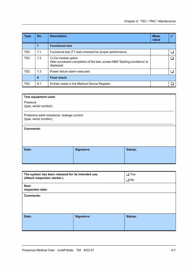
Chapter 4: TSC / TMC / Maintenance
Fresenius Medical Care multiFiltrate TM 6/03.07 4-7
7 Functional test
TSC 7.1 Functional test (T1 test) checked for proper performance.
TSC 7.2 Ci-Ca module option
After successful completion of the test, screen M86 'Starting conditions' is
displayed.
TSC 7.3 Power failure alarm executed.
8 Final check
TSC 8.1 Entries made in the Medical Device Register.
Test equipment used:
Pressure
(type, serial number):
________________________________________________________________________________________
Protective earth resistance, leakage current
(type, serial number):
________________________________________________________________________________________
Comments:
Date: Signature: Stamp:
The system has been released for its intended use.(Attach inspection sticker.)
Yes
No
Nextinspection date:
Comments:
Date: Signature: Stamp:
Type No. Description Meas. value
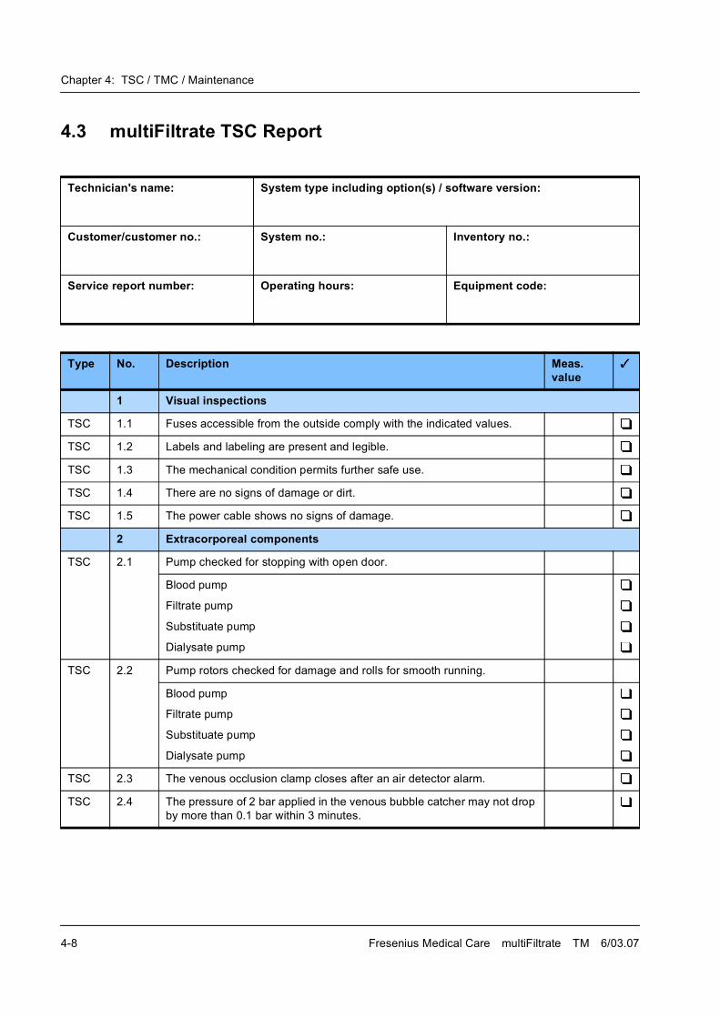
Chapter 4: TSC / TMC / Maintenance
4-8 Fresenius Medical Care multiFiltrate TM 6/03.07
4.3 multiFiltrate TSC Report
Technician's name: System type including option(s) / software version:
Customer/customer no.: System no.: Inventory no.:
Service report number: Operating hours: Equipment code:
Type No. Description Meas. value
1 Visual inspections
TSC 1.1 Fuses accessible from the outside comply with the indicated values.
TSC 1.2 Labels and labeling are present and legible.
TSC 1.3 The mechanical condition permits further safe use.
TSC 1.4 There are no signs of damage or dirt.
TSC 1.5 The power cable shows no signs of damage.
2 Extracorporeal components
TSC 2.1 Pump checked for stopping with open door.
Blood pump
Filtrate pump
Substituate pump
Dialysate pump
TSC 2.2 Pump rotors checked for damage and rolls for smooth running.
Blood pump
Filtrate pump
Substituate pump
Dialysate pump
TSC 2.3 The venous occlusion clamp closes after an air detector alarm.
TSC 2.4 The pressure of 2 bar applied in the venous bubble catcher may not drop
by more than 0.1 bar within 3 minutes.

Chapter 4: TSC / TMC / Maintenance
Fresenius Medical Care multiFiltrate TM 6/03.07 4-9
3 Ci-Ca module option: visual inspections
TSC 3.1 Colored markings of drop counters must be present.
TSC 3.2 Adhesive labels of citrate and calcium pumps are present and legible.
TSC 3.3 The mechanical condition permits further safe use.
TSC 3.4 There are no signs of damage or dirt.
TSC 3.5 Line holders must be present and undamaged.
4 Ci-Ca module option: extracorporeal components
TSC 4.1 Citrate drop counter checked for proper function
TSC 4.2 Calcium drop counter checked for proper function
TSC 4.3 Line occlusion of the pumps checked.
Citrate pump (pressure loss max. 10 mmHg/min)
Calcium pump (pressure loss max. 10 mmHg/min)
________
________
Type No. Description Meas. value
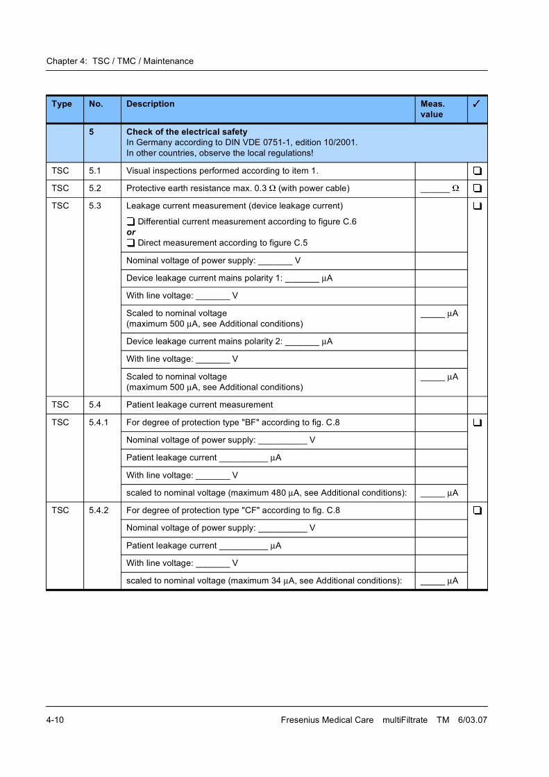
Chapter 4: TSC / TMC / Maintenance
4-10 Fresenius Medical Care multiFiltrate TM 6/03.07
5 Check of the electrical safety In Germany according to DIN VDE 0751-1, edition 10/2001.
In other countries, observe the local regulations!
TSC 5.1 Visual inspections performed according to item 1.
TSC 5.2 Protective earth resistance max. 0.3 (with power cable) ______
TSC 5.3 Leakage current measurement (device leakage current)
Differential current measurement according to figure C.6
or
Direct measurement according to figure C.5
Nominal voltage of power supply: _______ V
Device leakage current mains polarity 1: _______ �A
With line voltage: _______ V
Scaled to nominal voltage
(maximum 500 �A, see Additional conditions)
_____ �A
Device leakage current mains polarity 2: _______ �A
With line voltage: _______ V
Scaled to nominal voltage
(maximum 500 �A, see Additional conditions)
_____ �A
TSC 5.4 Patient leakage current measurement
TSC 5.4.1 For degree of protection type "BF" according to fig. C.8
Nominal voltage of power supply: __________ V
Patient leakage current __________ �A
With line voltage: _______ V
scaled to nominal voltage (maximum 480 �A, see Additional conditions): _____ �A
TSC 5.4.2 For degree of protection type "CF" according to fig. C.8
Nominal voltage of power supply: __________ V
Patient leakage current __________ �A
With line voltage: _______ V
scaled to nominal voltage (maximum 34 �A, see Additional conditions): _____ �A
Type No. Description Meas. value
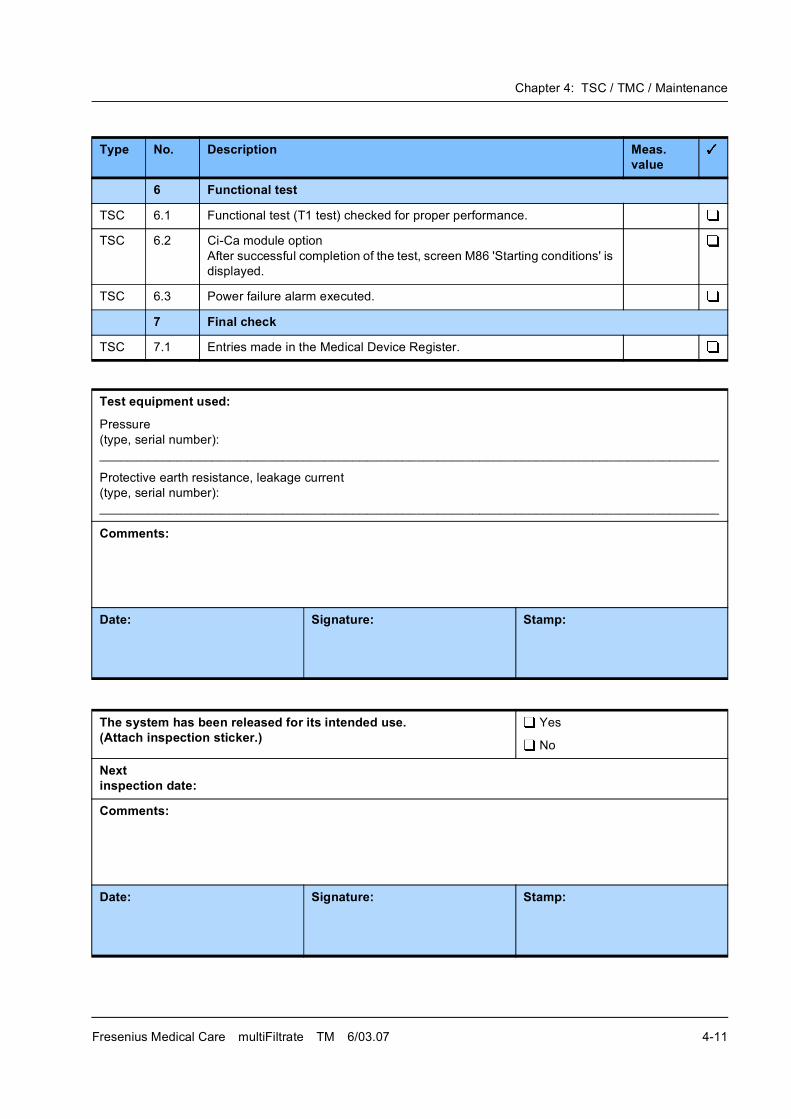
Chapter 4: TSC / TMC / Maintenance
Fresenius Medical Care multiFiltrate TM 6/03.07 4-11
6 Functional test
TSC 6.1 Functional test (T1 test) checked for proper performance.
TSC 6.2 Ci-Ca module option
After successful completion of the test, screen M86 'Starting conditions' is
displayed.
TSC 6.3 Power failure alarm executed.
7 Final check
TSC 7.1 Entries made in the Medical Device Register.
Test equipment used:
Pressure
(type, serial number):
________________________________________________________________________________________
Protective earth resistance, leakage current
(type, serial number):
________________________________________________________________________________________
Comments:
Date: Signature: Stamp:
The system has been released for its intended use.(Attach inspection sticker.)
Yes
No
Nextinspection date:
Comments:
Date: Signature: Stamp:
Type No. Description Meas. value
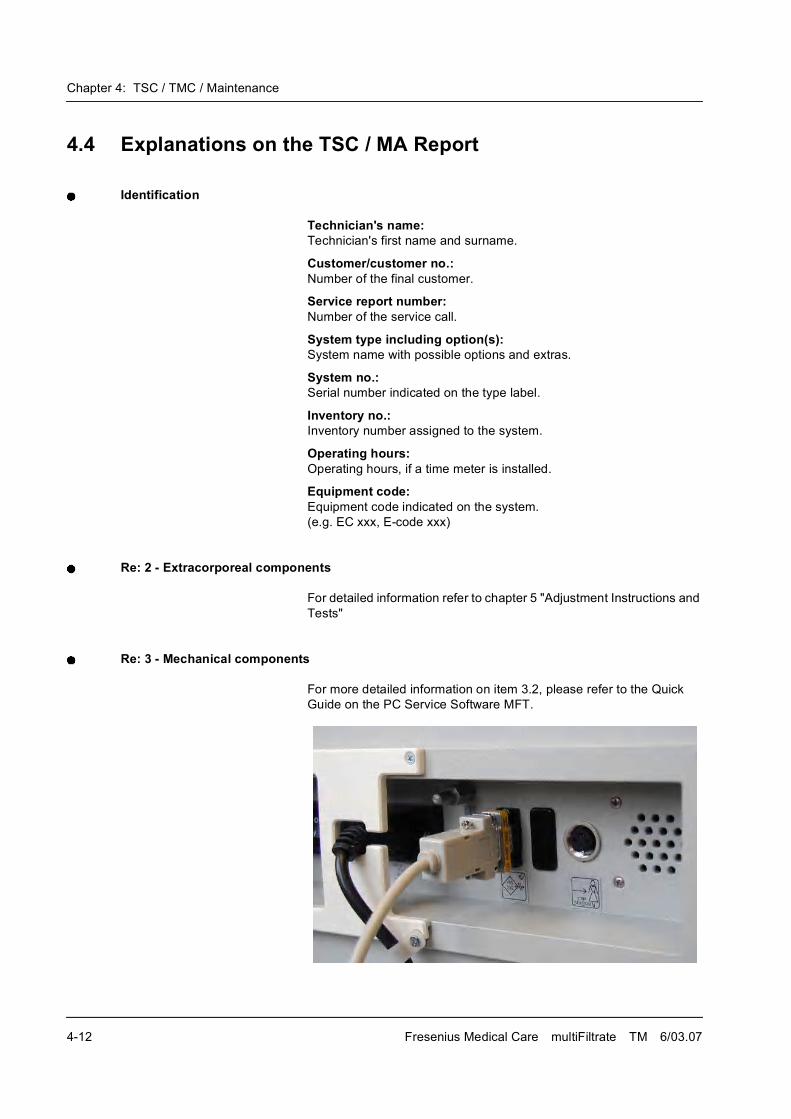
Chapter 4: TSC / TMC / Maintenance
4-12 Fresenius Medical Care multiFiltrate TM 6/03.07
4.4 Explanations on the TSC / MA Report
Identification
Technician's name:Technician's first name and surname.
Customer/customer no.:Number of the final customer.
Service report number:Number of the service call.
System type including option(s):System name with possible options and extras.
System no.:Serial number indicated on the type label.
Inventory no.:Inventory number assigned to the system.
Operating hours:Operating hours, if a time meter is installed.
Equipment code:Equipment code indicated on the system.
(e.g. EC xxx, E-code xxx)
Re: 2 - Extracorporeal components
For detailed information refer to chapter 5 "Adjustment Instructions and
Tests"
Re: 3 - Mechanical components
For more detailed information on item 3.2, please refer to the Quick
Guide on the PC Service Software MFT.
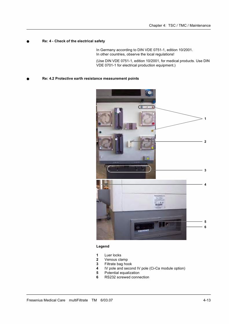
Chapter 4: TSC / TMC / Maintenance
Fresenius Medical Care multiFiltrate TM 6/03.07 4-13
Re: 4 - Check of the electrical safety
In Germany according to DIN VDE 0751-1, edition 10/2001.
In other countries, observe the local regulations!
(Use DIN VDE 0751-1, edition 10/2001, for medical products. Use DIN
VDE 0701-1 for electrical production equipment.)
Re: 4.2 Protective earth resistance measurement points
Legend
1 Luer locks
2 Venous clamp
3 Filtrate bag hook
4 IV pole and second IV pole (Ci-Ca module option)
5 Potential equalization
6 RS232 screwed connection
1
2
3
4
5
6
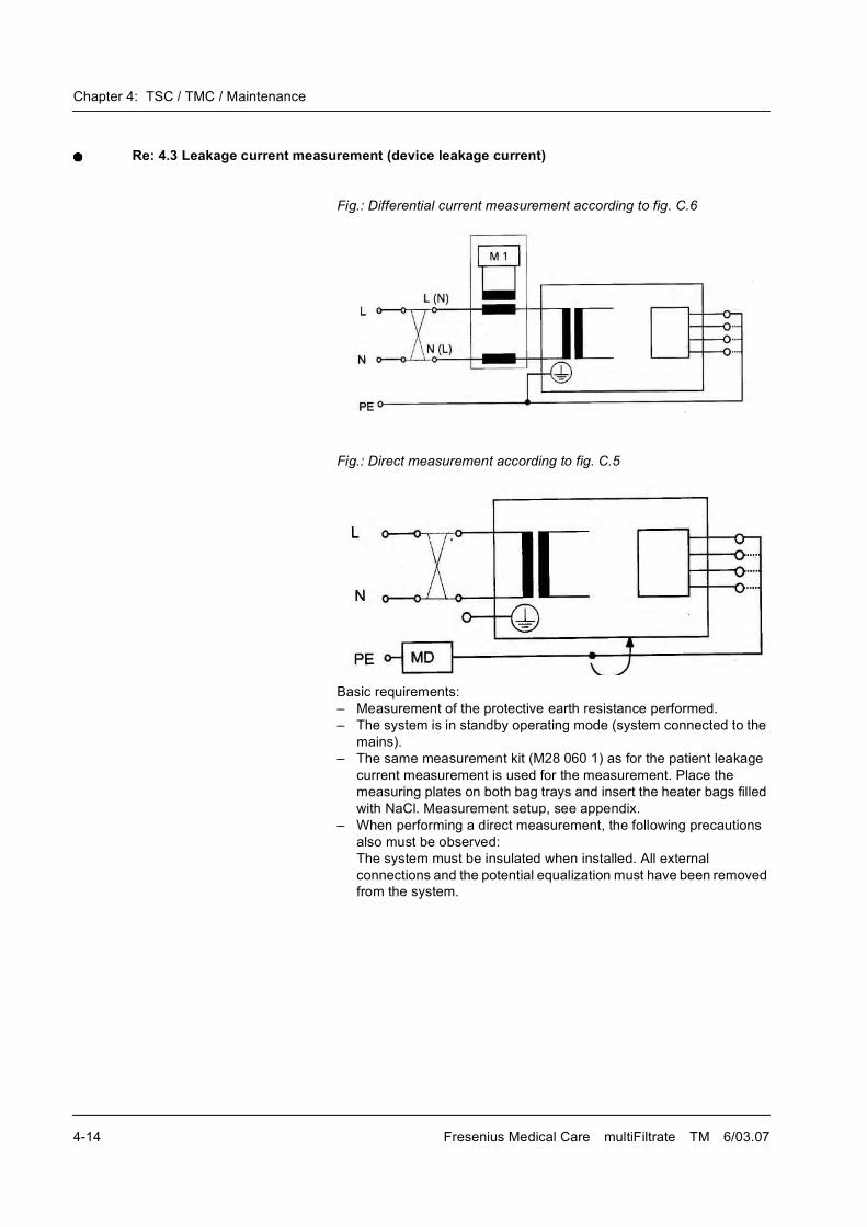
Chapter 4: TSC / TMC / Maintenance
4-14 Fresenius Medical Care multiFiltrate TM 6/03.07
Re: 4.3 Leakage current measurement (device leakage current)
Fig.: Differential current measurement according to fig. C.6
Fig.: Direct measurement according to fig. C.5
Basic requirements:
� Measurement of the protective earth resistance performed.
� The system is in standby operating mode (system connected to the
mains).
� The same measurement kit (M28 060 1) as for the patient leakage
current measurement is used for the measurement. Place the
measuring plates on both bag trays and insert the heater bags filled
with NaCl. Measurement setup, see appendix.
� When performing a direct measurement, the following precautions
also must be observed:
The system must be insulated when installed. All external
connections and the potential equalization must have been removed
from the system.
Chapter 4: TSC / TMC / Maintenance
Fresenius Medical Care multiFiltrate TM 6/03.07 4-15
Documentation covers the nominal voltage during the measurement
and the device leakage current at line voltage, scaled to the nominal line
voltage.Example:
Line voltage during measurement: 225 V
Device leakage current
for mains polarity 1: 38 µA
for mains polarity 2: 57 µA
Maximum value of both mains polarities: 57 µA
Nominal voltage of the power supply: 230 V
Scaled to nominal voltage: 58 µA
(58 µA: 225 V � 230 V = 58 µA)
Device leakage current < 500 µA: OK
Additional conditions:
If the device leakage current is higher than 90 % of the admissible alarm
limit (450 µA), the last measured value or the first measured value must
additionally be considered for the rating.
If the device leakage current considerably increased since the last
measurement or continuously increased since the first measurement
(creeping deterioration of the insulation), or if the sum composed of the
current value plus the difference since the last measurement is
> 500 µA, the measurement has not been passed.Example 1:
Leakage current: 470 µA
Last measured value: 450 A
470 + (470 � 450) = 470 + 20 = 490
OK
Example 2:
Leakage current: 470 µA
Last measured value: 390 µA
470 + (470 � 390) = 470 + 80 = 550
Not passed
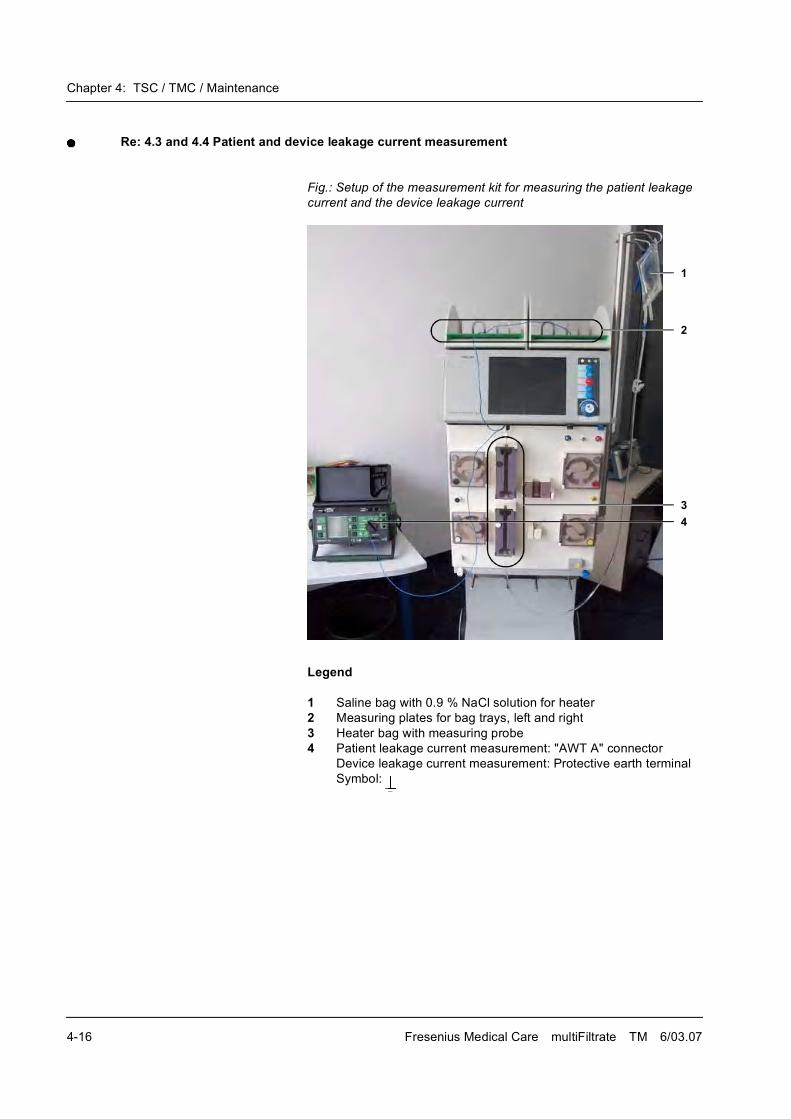
Chapter 4: TSC / TMC / Maintenance
4-16 Fresenius Medical Care multiFiltrate TM 6/03.07
Re: 4.3 and 4.4 Patient and device leakage current measurement
Fig.: Setup of the measurement kit for measuring the patient leakage
current and the device leakage current
Legend
1 Saline bag with 0.9 % NaCl solution for heater
2 Measuring plates for bag trays, left and right
3 Heater bag with measuring probe
4 Patient leakage current measurement: "AWT A" connector
Device leakage current measurement: Protective earth terminal
Symbol:
1
2
3
4

Chapter 4: TSC / TMC / Maintenance
Fresenius Medical Care multiFiltrate TM 6/03.07 4-17
Re: 4.4.1 - Patient leakage current measurement for degree of protection (BF)
Degree of protection type BF is applying to systems with ceramic
heater, operated at a line voltage of 220 V to 240 V and at a line
frequency of 60 Hz.
Fig.: Patient leakage current measurement according to figure C.8
Basic requirements:
� Measurement of the protective earth resistance performed.
� The system is in standby operating mode (system connected to the
mains).
� Neither the system nor the test equipment must be touched during
the measurement nor must a cable be connected to the serial
interface.
� The patient leakage current measurement kit (M28 060 1) is used for
the measurement. Place the measuring plates on both bag trays and
insert the heater bags filled with NaCl. Measurement setup, see
appendix.
Documentation covers the nominal voltage during the measurement
and the patient leakage current at line voltage, scaled to the nominal
line voltage.
Note on item 3 concerning device leakage measurement
The upper heater bag must be completely filled with NaCl solution so
that the electrode of the measuring probe is situated inside the solution.
Note on item 4 concerning device leakage measurement
The connection line to the measurement kit must be inserted in the
protective earth socket of the SECUTEST unit. If the measuring
instrument fails to provide this arrangement, the connection line must
be connected to a part of the multiFiltrate that is connected to the
protective earth, e.g. the venous clamp.
If the steps are not followed as described, a specific function will be
executed incorrectly or will not be executed at all, or will not produce the
desired effect.
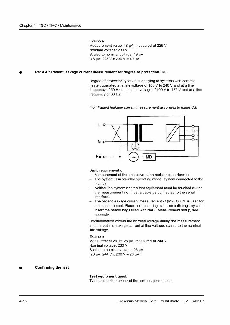
Chapter 4: TSC / TMC / Maintenance
4-18 Fresenius Medical Care multiFiltrate TM 6/03.07
Example:
Measurement value: 48 µA, measured at 225 V
Nominal voltage: 230 V
Scaled to nominal voltage: 49 µA
(48 µA: 225 V x 230 V = 49 µA)
Re: 4.4.2 Patient leakage current measurement for degree of protection (CF)
Degree of protection type CF is applying to systems with ceramic
heater, operated at a line voltage of 100 V to 240 V and at a line
frequency of 50 Hz or at a line voltage of 100 V to 127 V and at a line
frequency of 60 Hz.
Fig.: Patient leakage current measurement according to figure C.8
Basic requirements:
� Measurement of the protective earth resistance performed.
� The system is in standby operating mode (system connected to the
mains).
� Neither the system nor the test equipment must be touched during
the measurement nor must a cable be connected to the serial
interface.
� The patient leakage current measurement kit (M28 060 1) is used for
the measurement. Place the measuring plates on both bag trays and
insert the heater bags filled with NaCl. Measurement setup, see
appendix.
Documentation covers the nominal voltage during the measurement
and the patient leakage current at line voltage, scaled to the nominal
line voltage.
Example:
Measurement value: 28 µA, measured at 244 V
Nominal voltage: 230 V
Scaled to nominal voltage: 26 µA
(28 µA: 244 V x 230 V = 26 µA)
Confirming the test
Test equipment used:Type and serial number of the test equipment used.

Chapter 4: TSC / TMC / Maintenance
Fresenius Medical Care multiFiltrate TM 6/03.07 4-19
Comments:Irregularities encountered during the test will be recorded in this section.
Date, signature, stampPerformance of the test has to be confirmed by indicating date, tester's
signature and stamp.
Assessing the test
The system has been released for its intended use.(Attach inspection sticker.)
During the intended use of the system it must be ensured that the
system does not present a hazard to patients, employees or other third
parties.
Within the scope of the overall assessment, the tester must make a
definite decision whether the system may be used or not. The
responsible organization must immediately be informed of any defects
detected.
Next inspection date:The next inspection date has to be entered in the report.
The intervals specified by the manufacturer have to be respected!
Comments:Irregularities encountered during the assessment will be recorded in
this section.
Date, signature, stamp:Assessment of the initial start-up has to be confirmed by indicating date,
tester's signature and stamp.

Chapter 4: TSC / TMC / Maintenance
4-20 Fresenius Medical Care multiFiltrate TM 6/03.07
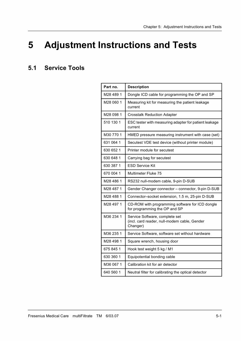
Chapter 5: Adjustment Instructions and Tests
Fresenius Medical Care multiFiltrate TM 6/03.07 5-1
5 Adjustment Instructions and Tests
5.1 Service Tools
Part no. Description
M28 489 1 Dongle ICD cable for programming the OP and SP
M28 060 1 Measuring kit for measuring the patient leakage
current
M28 098 1 Crosstalk Reduction Adapter
510 130 1 ESC tester with measuring adapter for patient leakage
current
M30 770 1 HMED pressure measuring instrument with case (set)
631 064 1 Secutest VDE test device (without printer module)
630 652 1 Printer module for secutest
630 648 1 Carrying bag for secutest
630 387 1 ESD Service Kit
670 004 1 Multimeter Fluke 75
M28 486 1 RS232 null-modem cable, 9-pin D-SUB
M28 487 1 Gender Changer connector � connector, 9-pin D-SUB
M28 488 1 Connector�socket extension, 1.5 m, 25-pin D-SUB
M28 497 1 CD-ROM with programming software for ICD dongle
for programming the OP and SP
M36 234 1 Service Software, complete set
(incl. card reader, null-modem cable, Gender
Changer)
M36 235 1 Service Software, software set without hardware
M28 498 1 Square wrench, housing door
675 845 1 Hook test weight 5 kg / M1
630 360 1 Equipotential bonding cable
M36 067 1 Calibration kit for air detector
640 560 1 Neutral filter for calibrating the optical detector
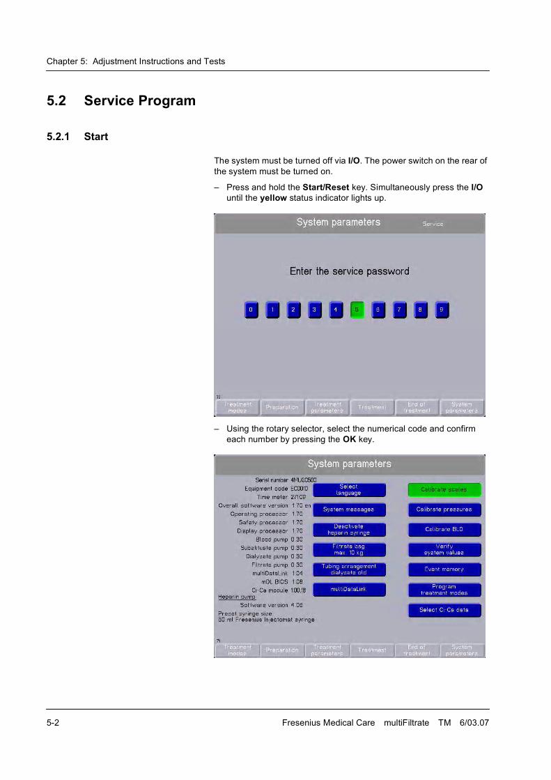
Chapter 5: Adjustment Instructions and Tests
5-2 Fresenius Medical Care multiFiltrate TM 6/03.07
5.2 Service Program
5.2.1 Start
The system must be turned off via I/O. The power switch on the rear of
the system must be turned on.
� Press and hold the Start/Reset key. Simultaneously press the I/O
until the yellow status indicator lights up.
� Using the rotary selector, select the numerical code and confirm
each number by pressing the OK key.
Chapter 5: Adjustment Instructions and Tests
Fresenius Medical Care multiFiltrate TM 6/03.07 5-3
After the password has been checked positively, all revisions are
displayed to the left of the screen. The menu fields of the Service
program are displayed to the right of the screen.
� Use the rotary selector to select the desired menu field and press
OK.
5.2.2 Selecting the Language
� Use the rotary selector to select the desired language and press OK.
� Turn off the system via the I/O key immediately thereafter.
� Once again turn on the system via the I/O key and restart the Service
program.
5.2.3 System Messages
Only the error messages (E XX) and warnings (W XX) of the previous
treatments are filtered out of the events memory (see below) and
displayed on the screen.
5.2.4 Deactivating and Activating the Heparin Pump
Permits activation and deactivation of the optional heparin syringe.
Screen display Machine status
Deactivate heparin syringe The heparin syringe is currently
active.
Activate heparin syringe The heparin syringe is currently
not active.
Note
If the system does not contain any installed heparin syringe, the
machine status should be set to Heparin syringe currently not active.
If the setting fails to reflect the proper machine status, a warning is
displayed during the T1 test.
Chapter 5: Adjustment Instructions and Tests
5-4 Fresenius Medical Care multiFiltrate TM 6/03.07
5.2.5 Filtrate Bag Monitoring Limit
Permits to set the monitoring limit to a value between 10 kg and 20 kg
on the filtrate scales.
5.2.6 Dialysate Tubing Arrangement
Permits to switch from old to "Fin" dialysate tubing arrangement and
vice versa in the preparation mode.
old Tubing system with heater bag downstream of the pump segment
"Fin" Tubing system with heater bag upstream of the pump segment
Screen display Machine status
Filtrate bag max. 5 kg Currently, the monitoring limit is
set to 5 kg.
Filtrate bag max. 10 kg Currently, the monitoring limit is
set to 10 kg.
Filtrate bag max. 20 kg Currently, the monitoring limit is
set to 20 kg.
Screen display Machine status
Tubing arrangement dialysate
old
Display of the old tubing
arrangement. Heater bag for
dialysate downstream of the
dialysate pump.
Tubing arrangement dialysate
"Fin"
Display of the new tubing
arrangement. Heater bag for
dialysate upstream of the
dialysate pump.
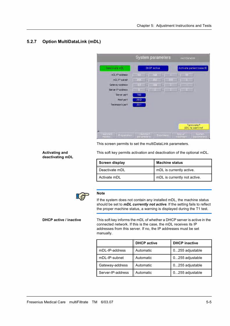
Chapter 5: Adjustment Instructions and Tests
Fresenius Medical Care multiFiltrate TM 6/03.07 5-5
5.2.7 Option MultiDataLink (mDL)
This screen permits to set the multiDataLink parameters.
Activating and deactivating mDL
This soft key permits activation and deactivation of the optional mDL.
DHCP active / inactive This soft key informs the mDL of whether a DHCP server is active in the
connected network. If this is the case, the mDL receives its IP
addresses from this server. If no, the IP addresses must be set
manually.
Screen display Machine status
Deactivate mDL mDL is currently active.
Activate mDL mDL is currently not active.
Note
If the system does not contain any installed mDL, the machine status
should be set to mDL currently not active. If the setting fails to reflect
the proper machine status, a warning is displayed during the T1 test.
DHCP active DHCP inactive
mDL-IP-address Automatic 0...255 adjustable
mDL-IP-subnet Automatic 0...255 adjustable
Gateway-address Automatic 0...255 adjustable
Server-IP-address Automatic 0...255 adjustable
Chapter 5: Adjustment Instructions and Tests
5-6 Fresenius Medical Care multiFiltrate TM 6/03.07
� Use the rotary selector to select the Terminate? [OK] to confirm! field and press OK.
Activating/deactivating the Patient/Case ID
This soft key permits activation and deactivation of the optional
patient/case ID.
Server-port 0...65535 adjustable
Default value: 700
0...65535 adjustable
Default value: 700
Host-port 0...65535 adjustable
Default value: 2512
0...65535 adjustable
Default value: 2512
Technician's port 0...65535 adjustable
Default value: 2511
0...65535 adjustable
Default value: 2511
DHCP active DHCP inactive
Note
Before setting the mDL parameters, please clarify with the responsible
hospital network administrator whether a DHCP server is available for
automatically assigning the IP addresses. If no, the administrator has to
specify defined addresses which will then have to be entered manually.
The port numbers depend on the application which further processes
the multiFiltrate data. The administrator of this software will have to
specify the appropriate values if these are different from default values.
Screen display Machine status
Deactivate patient/case ID The patient/case ID is currently
active
Activate patient/case ID The patient/case ID is currently
not active
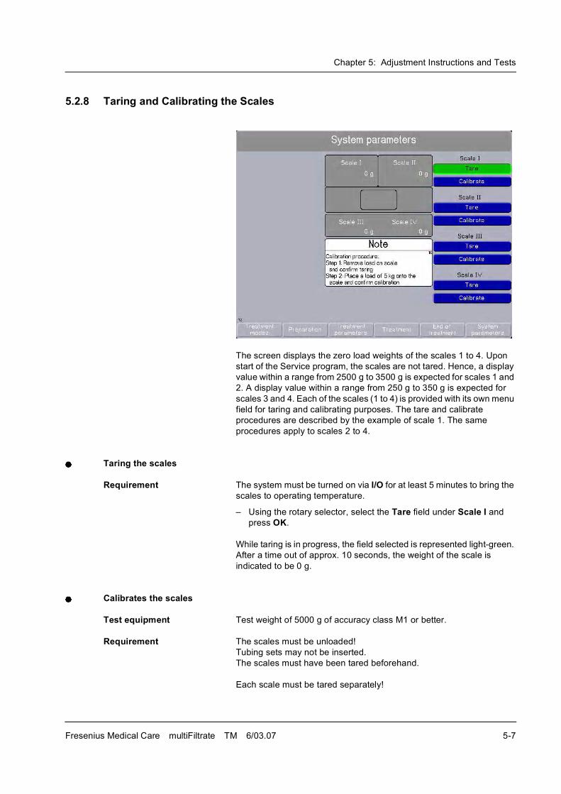
Chapter 5: Adjustment Instructions and Tests
Fresenius Medical Care multiFiltrate TM 6/03.07 5-7
5.2.8 Taring and Calibrating the Scales
The screen displays the zero load weights of the scales 1 to 4. Upon
start of the Service program, the scales are not tared. Hence, a display
value within a range from 2500 g to 3500 g is expected for scales 1 and
2. A display value within a range from 250 g to 350 g is expected for
scales 3 and 4. Each of the scales (1 to 4) is provided with its own menu
field for taring and calibrating purposes. The tare and calibrate
procedures are described by the example of scale 1. The same
procedures apply to scales 2 to 4.
Taring the scales
Requirement The system must be turned on via I/O for at least 5 minutes to bring the
scales to operating temperature.
� Using the rotary selector, select the Tare field under Scale I and
press OK.
While taring is in progress, the field selected is represented light-green.
After a time out of approx. 10 seconds, the weight of the scale is
indicated to be 0 g.
Calibrates the scales
Test equipment Test weight of 5000 g of accuracy class M1 or better.
Requirement The scales must be unloaded!
Tubing sets may not be inserted.
The scales must have been tared beforehand.
Each scale must be tared separately!
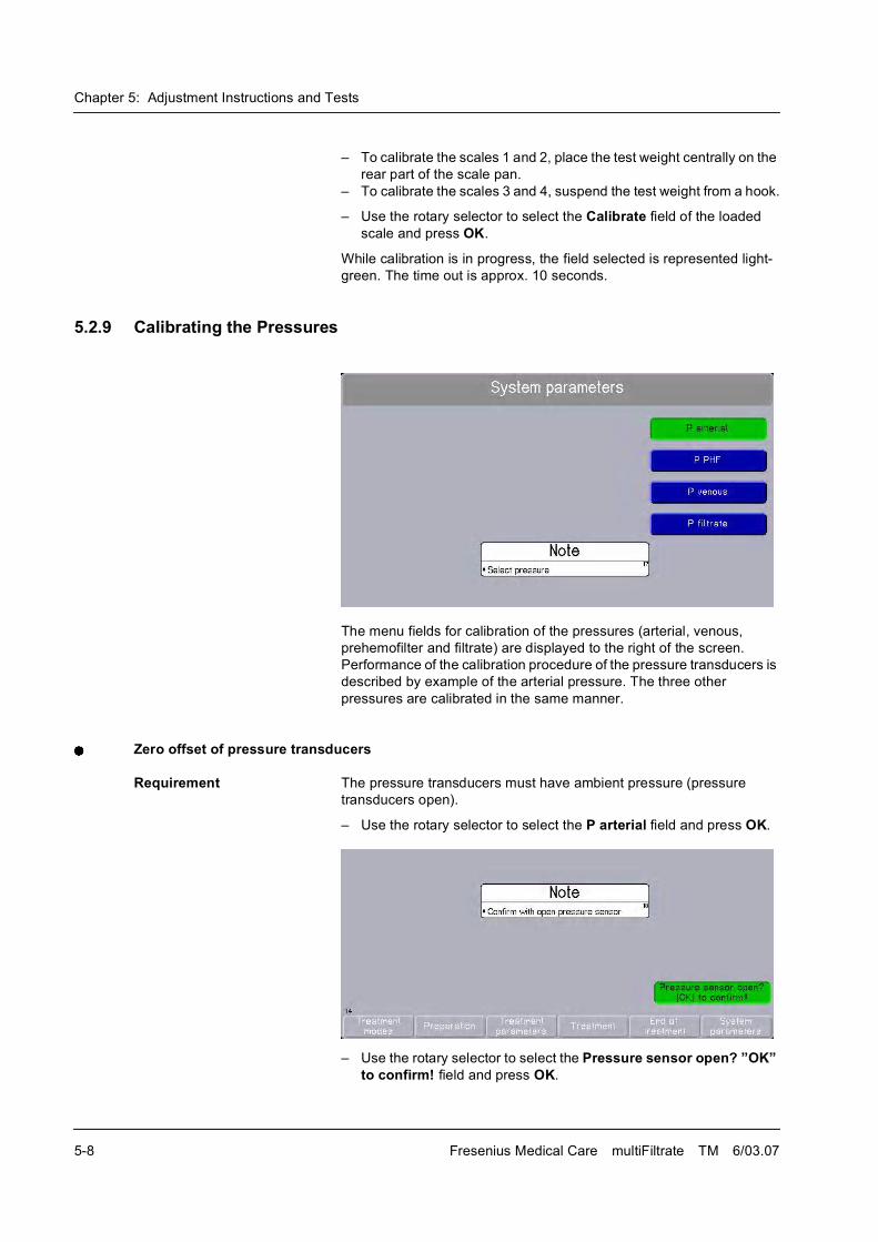
Chapter 5: Adjustment Instructions and Tests
5-8 Fresenius Medical Care multiFiltrate TM 6/03.07
� To calibrate the scales 1 and 2, place the test weight centrally on the
rear part of the scale pan.
� To calibrate the scales 3 and 4, suspend the test weight from a hook.
� Use the rotary selector to select the Calibrate field of the loaded
scale and press OK.
While calibration is in progress, the field selected is represented light-
green. The time out is approx. 10 seconds.
5.2.9 Calibrating the Pressures
The menu fields for calibration of the pressures (arterial, venous,
prehemofilter and filtrate) are displayed to the right of the screen.
Performance of the calibration procedure of the pressure transducers is
described by example of the arterial pressure. The three other
pressures are calibrated in the same manner.
Zero offset of pressure transducers
Requirement The pressure transducers must have ambient pressure (pressure
transducers open).
� Use the rotary selector to select the P arterial field and press OK.
� Use the rotary selector to select the Pressure sensor open? �OK� to confirm! field and press OK.
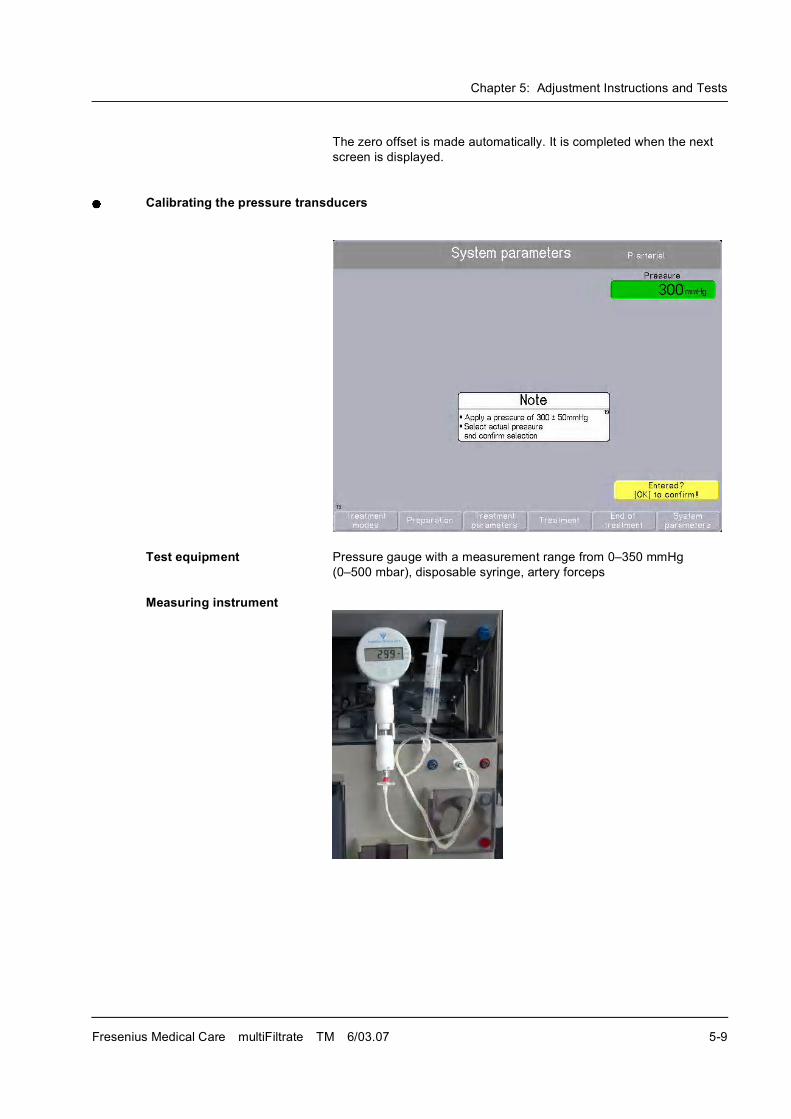
Chapter 5: Adjustment Instructions and Tests
Fresenius Medical Care multiFiltrate TM 6/03.07 5-9
The zero offset is made automatically. It is completed when the next
screen is displayed.
Calibrating the pressure transducers
Test equipment Pressure gauge with a measurement range from 0�350 mmHg
(0�500 mbar), disposable syringe, artery forceps
Measuring instrument
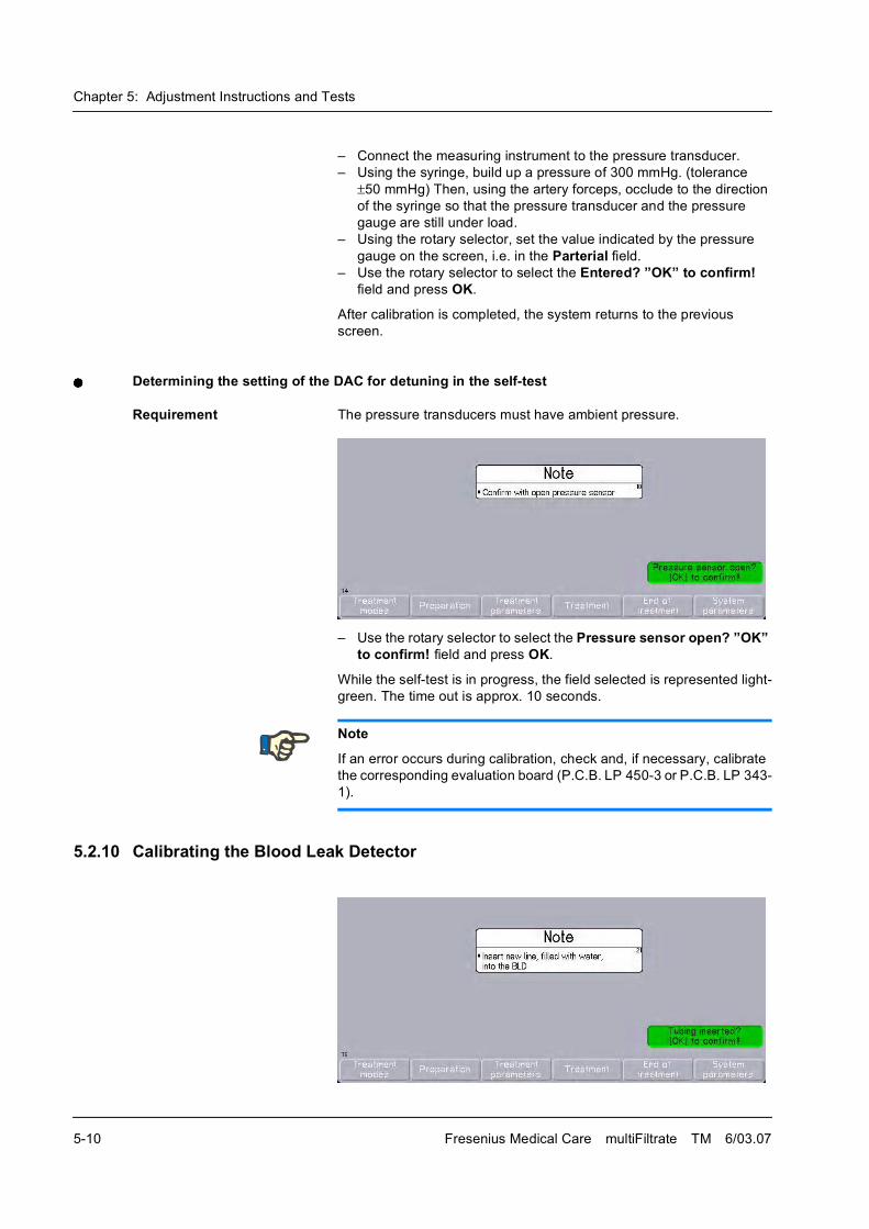
Chapter 5: Adjustment Instructions and Tests
5-10 Fresenius Medical Care multiFiltrate TM 6/03.07
� Connect the measuring instrument to the pressure transducer.
� Using the syringe, build up a pressure of 300 mmHg. (tolerance
�50 mmHg) Then, using the artery forceps, occlude to the direction
of the syringe so that the pressure transducer and the pressure
gauge are still under load.
� Using the rotary selector, set the value indicated by the pressure
gauge on the screen, i.e. in the Parterial field.
� Use the rotary selector to select the Entered? �OK� to confirm! field and press OK.
After calibration is completed, the system returns to the previous
screen.
Determining the setting of the DAC for detuning in the self-test
Requirement The pressure transducers must have ambient pressure.
� Use the rotary selector to select the Pressure sensor open? �OK� to confirm! field and press OK.
While the self-test is in progress, the field selected is represented light-
green. The time out is approx. 10 seconds.
5.2.10 Calibrating the Blood Leak Detector
Note
If an error occurs during calibration, check and, if necessary, calibrate
the corresponding evaluation board (P.C.B. LP 450-3 or P.C.B. LP 343-
1).
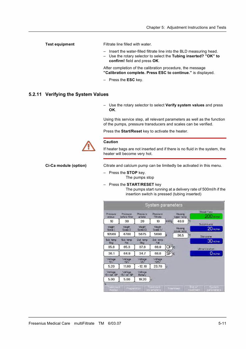
Chapter 5: Adjustment Instructions and Tests
Fresenius Medical Care multiFiltrate TM 6/03.07 5-11
Test equipment Filtrate line filled with water.
� Insert the water-filled filtrate line into the BLD measuring head.
� Use the rotary selector to select the Tubing inserted? �OK� to confirm! field and press OK.
After completion of the calibration procedure, the message
�Calibration complete. Press ESC to continue.� is displayed.
� Press the ESC key.
5.2.11 Verifying the System Values
� Use the rotary selector to select Verify system values and press
OK.
Using this service step, all relevant parameters as well as the function
of the pumps, pressure transducers and scales can be verified.
Press the Start/Reset key to activate the heater.
Ci-Ca module (option) Citrate and calcium pump can be limitedly be activated in this menu.
� Press the STOP key.
The pumps stop
� Press the START/RESET key
The pumps start running at a delivery rate of 500ml/h if the
insertion switch is pressed (tubing inserted)
Caution
If heater bags are not inserted and if there is no fluid in the system, the
heater will become very hot.
Chapter 5: Adjustment Instructions and Tests
5-12 Fresenius Medical Care multiFiltrate TM 6/03.07
Display of pressure values (venous, PHF, arterial, and filtrate);
resolution 1 mmHg. With open pressure transducers, the display must
show values within a range from � 5 mmHg to 5 mmHg.
Display of weights (scale 1, scale 2, scale 3, and scale 4); resolution
1 g.
Display of the temperatures of the heaters for the sensors of the
operating processor (OP) and the safety processor (SP).
Display of system voltages. This display is only intended for a rough
check of the system voltages. Owing to the hardware and software
conversions, the accuracy is within a range of ±5% only. Use a
calibrated multimeter to perform a check for the indicated range directly
on P.C.B. LP 124 or LP 244 SR/BR (SP/OP).
The housing temperatures are determined by means of the sensors of
the scales. These sensors transmit their values to the safety processor.
Screen Heater location
Sub. temp. Bag Lower heater, bag sensor
Sub. temp. Foil Lower heater, foil sensor
Dial. temp. Bag Upper heater, bag sensor
Dial. temp. Foil Upper heater, foil sensor
Screen Desired value Voltage
Voltage +5 V 5.0 - 5.3 V Logic voltage
Voltage
+12 V
11.5 - 12.3 V Supply voltage
Voltage -
12 V
-(11.2 - 12.3 V) Supply voltage
Voltage
+24 V
23.0 - 24.0 V Supply voltage
Voltage +5 V
ref. OS
5.05 - 4.95 V Supply voltage of the operating
processor for the A-D converter
Voltage +5 V
ref. SS
5.05 - 4.95 V Supply voltage of the safety
processor for the A-D converter
Battery
voltage
18.0 - 22.5 V Battery terminal voltage
Screen Temperature
Housing Upper temp. Mean value of the sensors of the
two upper scales
Housing Lower temp. Mean value of the sensors of the
two lower scales
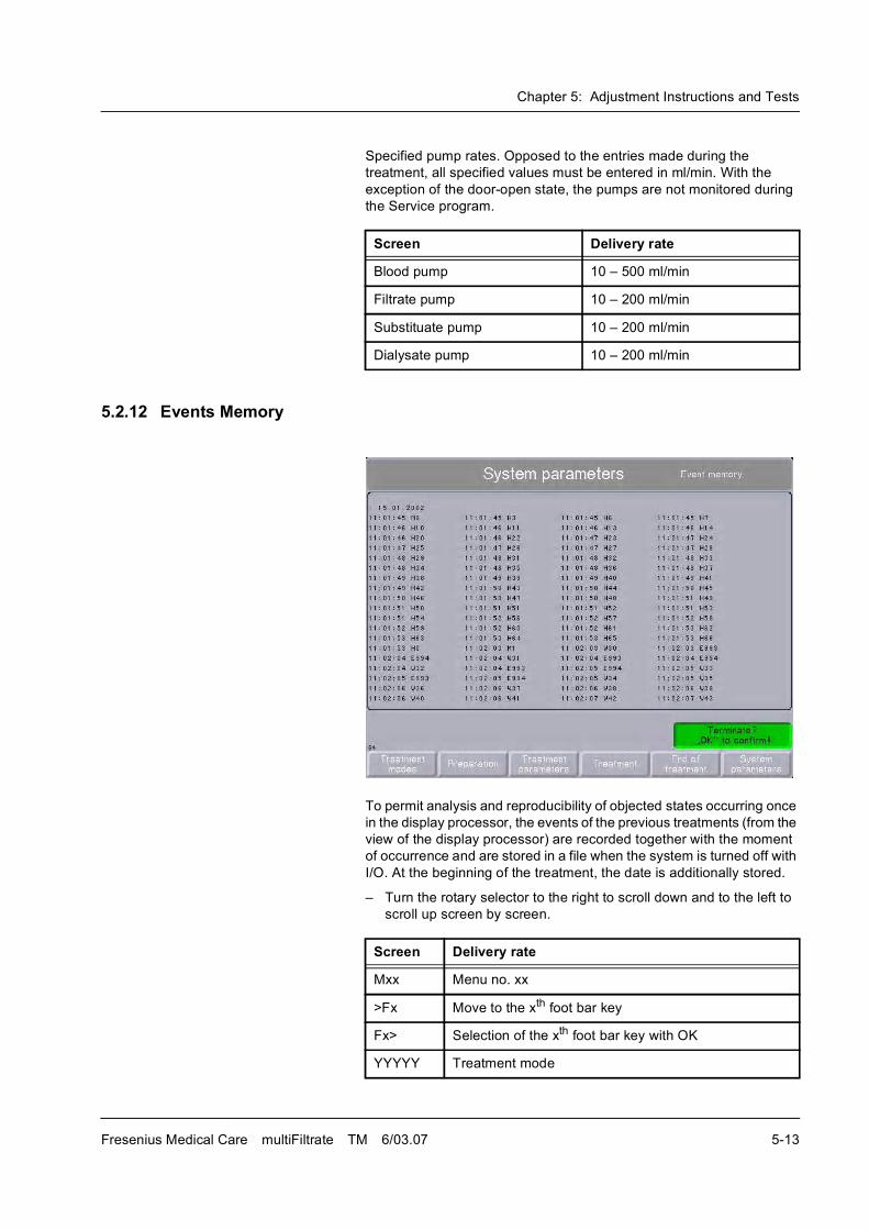
Chapter 5: Adjustment Instructions and Tests
Fresenius Medical Care multiFiltrate TM 6/03.07 5-13
Specified pump rates. Opposed to the entries made during the
treatment, all specified values must be entered in ml/min. With the
exception of the door-open state, the pumps are not monitored during
the Service program.
5.2.12 Events Memory
To permit analysis and reproducibility of objected states occurring once
in the display processor, the events of the previous treatments (from the
view of the display processor) are recorded together with the moment
of occurrence and are stored in a file when the system is turned off with
I/O. At the beginning of the treatment, the date is additionally stored.
� Turn the rotary selector to the right to scroll down and to the left to
scroll up screen by screen.
Screen Delivery rate
Blood pump 10 � 500 ml/min
Filtrate pump 10 � 200 ml/min
Substituate pump 10 � 200 ml/min
Dialysate pump 10 � 200 ml/min
Screen Delivery rate
Mxx Menu no. xx
>Fx Move to the xth foot bar key
Fx> Selection of the xth foot bar key with OK
YYYYY Treatment mode
Chapter 5: Adjustment Instructions and Tests
5-14 Fresenius Medical Care multiFiltrate TM 6/03.07
y Internal operating mode
Hxx Display of note no. xx
Wxxx Display of warning no. xxx
Exxx Display of error no. xxx
H0 Hiding of the respective display
->x Turn right by x steps before function key
<-4 Turn left by x steps before function key
.->x Turn by x steps took place before a preceding H, W or
F entry (in M61 only).
Oxx Internal options command
BRxx Blood flow in ml/min
ARxxxx Substituate rate in ml/h; plasma rate in ml/min
DRxxxx Dialysate rate in ml/h
SVxxxx Plasma volume in ml
EExxxx Ultrafiltration in ml/h
UZxxxx UF goal in ml/h
TSxx Temperature in 0.1 �C
ABxx Bolus anticoagulation in 0.1 ml
KA Continuous anticoagulation in 0.1 ml/h
SPVxxxx Rinse volume in ml
UFVxxxx UF volume in ml
RIVxxxx Reinfusion volume in ml
DHxxx Display brightness in %
LSxxx Volume of audible alarm in %
SCxxx Pressure in mmHg
AHxxx Upper arterial pressure limit in mmHg
ALxxx Lower arterial pressure limit in mmHg
VHxxx Upper venous pressure limit in mmHg
VLxxx Lower venous pressure limit in mmHg
THxxx Upper TMP/pF pressure limit in mmHg
Screen Delivery rate
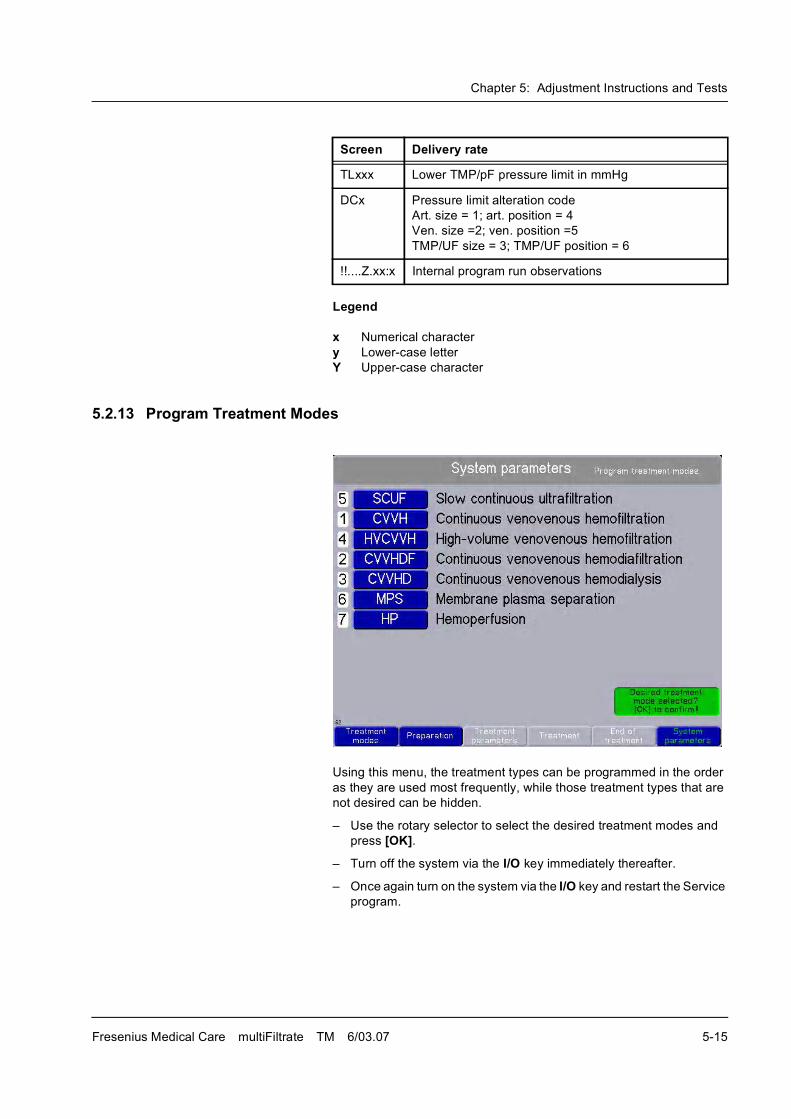
Chapter 5: Adjustment Instructions and Tests
Fresenius Medical Care multiFiltrate TM 6/03.07 5-15
Legend
x Numerical character
y Lower-case letter
Y Upper-case character
5.2.13 Program Treatment Modes
Using this menu, the treatment types can be programmed in the order
as they are used most frequently, while those treatment types that are
not desired can be hidden.
� Use the rotary selector to select the desired treatment modes and
press [OK].
� Turn off the system via the I/O key immediately thereafter.
� Once again turn on the system via the I/O key and restart the Service
program.
TLxxx Lower TMP/pF pressure limit in mmHg
DCx Pressure limit alteration code
Art. size = 1; art. position = 4
Ven. size =2; ven. position =5
TMP/UF size = 3; TMP/UF position = 6
!!....Z.xx:x Internal program run observations
Screen Delivery rate
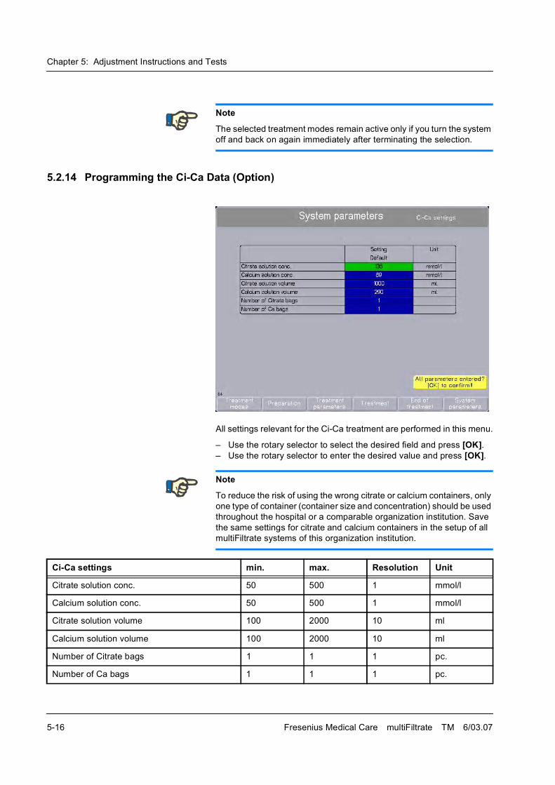
Chapter 5: Adjustment Instructions and Tests
5-16 Fresenius Medical Care multiFiltrate TM 6/03.07
5.2.14 Programming the Ci-Ca Data (Option)
All settings relevant for the Ci-Ca treatment are performed in this menu.
� Use the rotary selector to select the desired field and press [OK].� Use the rotary selector to enter the desired value and press [OK].
Note
The selected treatment modes remain active only if you turn the system
off and back on again immediately after terminating the selection.
Note
To reduce the risk of using the wrong citrate or calcium containers, only
one type of container (container size and concentration) should be used
throughout the hospital or a comparable organization institution. Save
the same settings for citrate and calcium containers in the setup of all
multiFiltrate systems of this organization institution.
Ci-Ca settings min. max. Resolution Unit
Citrate solution conc. 50 500 1 mmol/l
Calcium solution conc. 50 500 1 mmol/l
Citrate solution volume 100 2000 10 ml
Calcium solution volume 100 2000 10 ml
Number of Citrate bags 1 1 1 pc.
Number of Ca bags 1 1 1 pc.
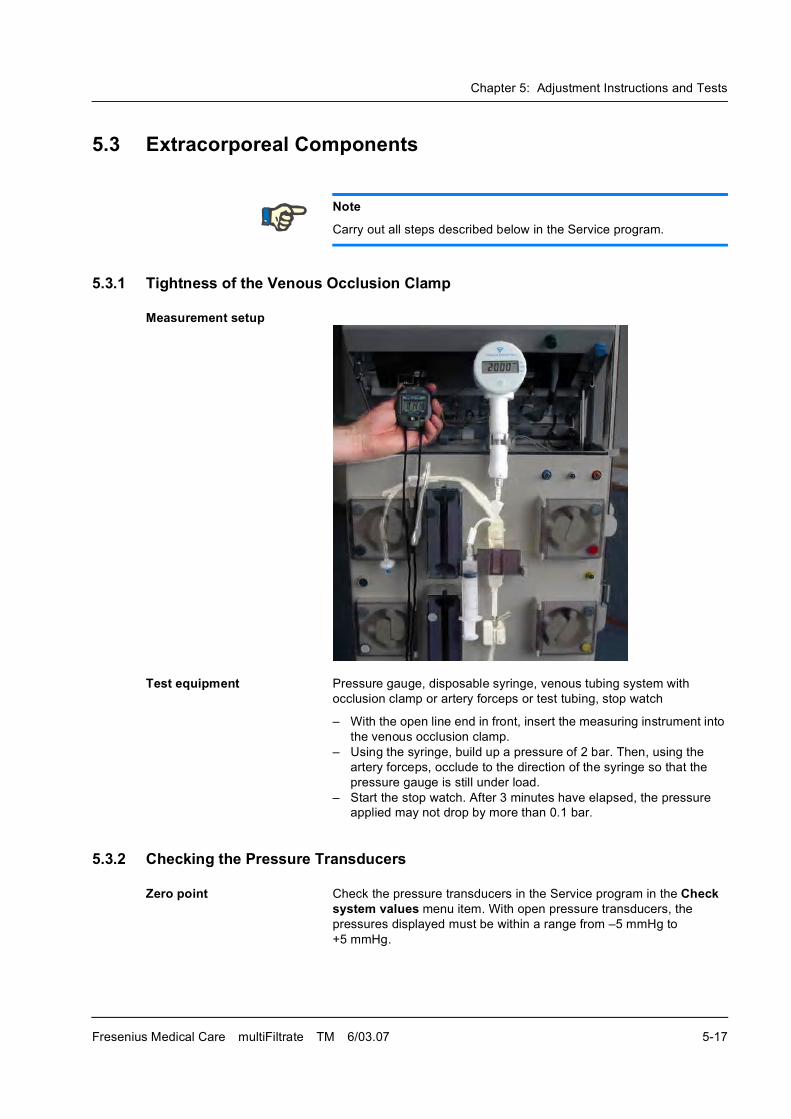
Chapter 5: Adjustment Instructions and Tests
Fresenius Medical Care multiFiltrate TM 6/03.07 5-17
5.3 Extracorporeal Components
5.3.1 Tightness of the Venous Occlusion Clamp
Measurement setup
Test equipment Pressure gauge, disposable syringe, venous tubing system with
occlusion clamp or artery forceps or test tubing, stop watch
� With the open line end in front, insert the measuring instrument into
the venous occlusion clamp.
� Using the syringe, build up a pressure of 2 bar. Then, using the
artery forceps, occlude to the direction of the syringe so that the
pressure gauge is still under load.
� Start the stop watch. After 3 minutes have elapsed, the pressure
applied may not drop by more than 0.1 bar.
5.3.2 Checking the Pressure Transducers
Zero point Check the pressure transducers in the Service program in the Check system values menu item. With open pressure transducers, the
pressures displayed must be within a range from �5 mmHg to
+5 mmHg.
Note
Carry out all steps described below in the Service program.
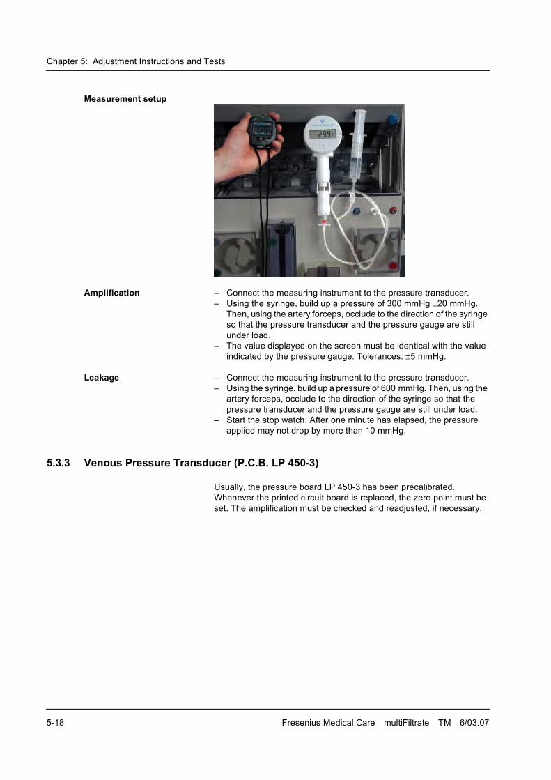
Chapter 5: Adjustment Instructions and Tests
5-18 Fresenius Medical Care multiFiltrate TM 6/03.07
Measurement setup
Amplification � Connect the measuring instrument to the pressure transducer.
� Using the syringe, build up a pressure of 300 mmHg �20 mmHg.
Then, using the artery forceps, occlude to the direction of the syringe
so that the pressure transducer and the pressure gauge are still
under load.
� The value displayed on the screen must be identical with the value
indicated by the pressure gauge. Tolerances: �5 mmHg.
Leakage � Connect the measuring instrument to the pressure transducer.
� Using the syringe, build up a pressure of 600 mmHg. Then, using the
artery forceps, occlude to the direction of the syringe so that the
pressure transducer and the pressure gauge are still under load.
� Start the stop watch. After one minute has elapsed, the pressure
applied may not drop by more than 10 mmHg.
5.3.3 Venous Pressure Transducer (P.C.B. LP 450-3)
Usually, the pressure board LP 450-3 has been precalibrated.
Whenever the printed circuit board is replaced, the zero point must be
set. The amplification must be checked and readjusted, if necessary.
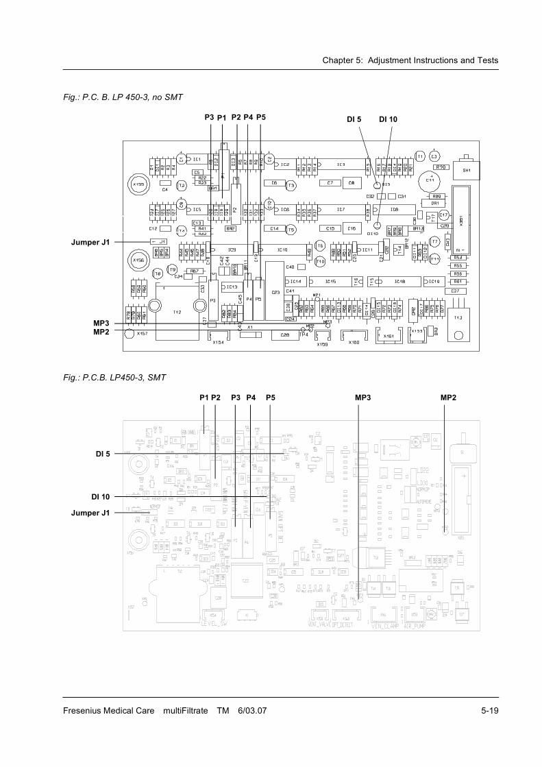
Chapter 5: Adjustment Instructions and Tests
Fresenius Medical Care multiFiltrate TM 6/03.07 5-19
Fig.: P.C. B. LP 450-3, no SMT
Fig.: P.C.B. LP450-3, SMT
Jumper J1
DI 10DI 5P1 P2P3 P4 P5
MP3MP2
Jumper J1
DI 10
DI 5
P1 P2 P3 P4 P5 MP3 MP2
Chapter 5: Adjustment Instructions and Tests
5-20 Fresenius Medical Care multiFiltrate TM 6/03.07
Setting the zero point Setting the zero point with open pressure transducers.
� Connect the negative pole of the multimeter to MP3 (0 V).
� Connect the positive pole of the multimeter to MP2.
� Use the potentiometer P3 to set the following voltage.
Setting the amplification For verification and setting purposes, apply a pressure of 300 mmHg
�20 mmHg to the pressure transducers.
� Use the potentiometer P4 to set the following voltage.
5.3.4 Air Detector (P.C.B. LP 450-3)
Test equipment Adjusting block and checking (reference) block M36 067 1
Check using the checking block (red)
� Set the jumper J1 / P.C.B. LP 450-3 to the �operation� position
(NORM OP).
� Fill the spherical recesses of the checking block with grease and
remove any excess grease so that only the recesses themselves will
be struck with grease.
� Place the greased checking block into the drip chamber holder. It
must be ensured that the ultrasonic sensors must correctly click into
place into the spherical recesses of the adjusting block. The block
must not touch the holder wall, but must hang freely between the
sensors.
Desired function: The LEDs DI 5 and DI 10 on the P.C.B. LP 450-3 are
light.
If the desired function fails to be fulfilled, the ultrasonic detector must be
set.
Check using the adjusting block (grey)
� Set the jumper J1 / P.C.B. LP 450-3 to the �operation� position
(NORM OP).
� Fill the spherical recesses of the adjusting block with grease and
remove any excess grease so that only the recesses themselves will
be struck with grease.
� Place the greased adjusting block into the drip chamber holder. It
must be ensured that the ultrasonic sensors must correctly click into
place into the spherical recesses of the adjusting block. The block
must not touch the holder wall, but must hang freely between the
sensors.
Pressure transducer Voltage
Venous 3 V �0.2 V
Pressure transducer Voltage
Venous 5.9 V �0.2 V
Note
Whenever the P.C.B. LP 450-3 is replaced, the air detector must be
recalibrated.
Chapter 5: Adjustment Instructions and Tests
Fresenius Medical Care multiFiltrate TM 6/03.07 5-21
Desired function: The LEDs DI 5 and DI 10 on the P.C.B. LP 450-3 are
dark.
If the desired function fails to be fulfilled, the ultrasonic detector must be
set.
� Take the adjusting block out of the drip chamber holder and
completely remove the grease from the drip chamber holder, only
using non-pilling fabric and disinfectants authorized for this purpose.
Calibration � Set the jumper J1 / P.C.B. LP 450-3 to the �calibration� position
(CALIB).
� Fill the spherical recesses of the adjusting block with grease and
remove any excess grease so that only the recesses themselves will
be struck with grease.
� Place the greased adjusting block into the drip chamber holder. It
must be ensured that the ultrasonic sensors must correctly click into
place into the spherical recesses of the adjusting block. The block
must not touch the holder wall, but must hang freely between the
sensors.
� Turn potentiometer 1 and then potentiometer 2 on P.C.B. LP 450-3
until the LEDs DI 5 and DI 10 on P.C.B. LP 450-3 are dark.
� Slowly (caution: time constant) turn potentiometer 1 / P.C.B. LP 450-
3 back until the LED DI 5 on P.C.B. LP 450-3 lights.
� Slowly (caution: time constant) turn potentiometer 2 / P.C.B. LP 450-
3 back until the LED DI 10 on P.C.B. LP 450-3 lights.
� Set the jumper J1 / P.C.B. LP 450-3 to the �operation� position
(NORM OP).
Desired function: The LEDs DI 5 and DI 10 on the P.C.B. LP 450-3 are
dark.
� Take the adjusting block out of the drip chamber holder and
completely remove the grease from the drip chamber holder, only
using non-pilling fabric and disinfectants authorized for this purpose.
5.3.5 Optical Detector Sensing Opaque / Non-Opaque Fluid (P.C.B. LP 450-3)
Calibration � Start the Service program and select "Verify system values".
� Hold the neutral filter (640 560 1) (to be used in 2 layers) into the
optical detector. Close the flap to minimize external light.
� Slowly turn the potentiometer P5 on P.C.B. LP 450-3 until the
audible signal turns silent.
� Slowly turn potentiometer P5 until the audible signal is sounded.
Then turn it for another half-revolution.
5.3.6 Arterial / Filtrate / PHF Pressure Transducers (P.C.B. LP 343-1)
Usually, the pressure boards LP 343-1 have been precalibrated.
Whenever the printed circuit boards are replaced, the zero point must
be set. The amplification must be checked and readjusted, if necessary.
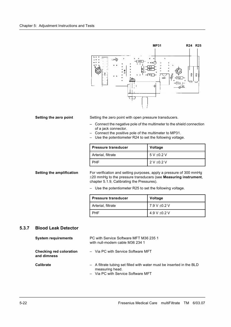
Chapter 5: Adjustment Instructions and Tests
5-22 Fresenius Medical Care multiFiltrate TM 6/03.07
Setting the zero point Setting the zero point with open pressure transducers.
� Connect the negative pole of the multimeter to the shield connection
of a jack connector.
� Connect the positive pole of the multimeter to MP31.
� Use the potentiometer R24 to set the following voltage.
Setting the amplification For verification and setting purposes, apply a pressure of 300 mmHg
�20 mmHg to the pressure transducers (see Measuring instrument, chapter 5.1.9, Calibrating the Pressures).
� Use the potentiometer R25 to set the following voltage.
5.3.7 Blood Leak Detector
System requirements PC with Service Software MFT M36 235 1
with null-modem cable M36 234 1
Checking red coloration and dimness
� Via PC with Service Software MFT
Calibrate � A filtrate tubing set filled with water must be inserted in the BLD
measuring head.
� Via PC with Service Software MFT
MP31 R24 R25
Pressure transducer Voltage
Arterial, filtrate 5 V �0.2 V
PHF 2 V �0.2 V
Pressure transducer Voltage
Arterial, filtrate 7.9 V �0.2 V
PHF 4.9 V �0.2 V
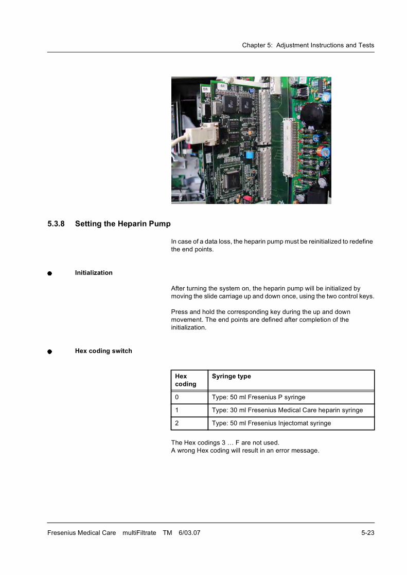
Chapter 5: Adjustment Instructions and Tests
Fresenius Medical Care multiFiltrate TM 6/03.07 5-23
5.3.8 Setting the Heparin Pump
In case of a data loss, the heparin pump must be reinitialized to redefine
the end points.
Initialization
After turning the system on, the heparin pump will be initialized by
moving the slide carriage up and down once, using the two control keys.
Press and hold the corresponding key during the up and down
movement. The end points are defined after completion of the
initialization.
Hex coding switch
The Hex codings 3 � F are not used.
A wrong Hex coding will result in an error message.
Hex coding
Syringe type
0 Type: 50 ml Fresenius P syringe
1 Type: 30 ml Fresenius Medical Care heparin syringe
2 Type: 50 ml Fresenius Injectomat syringe
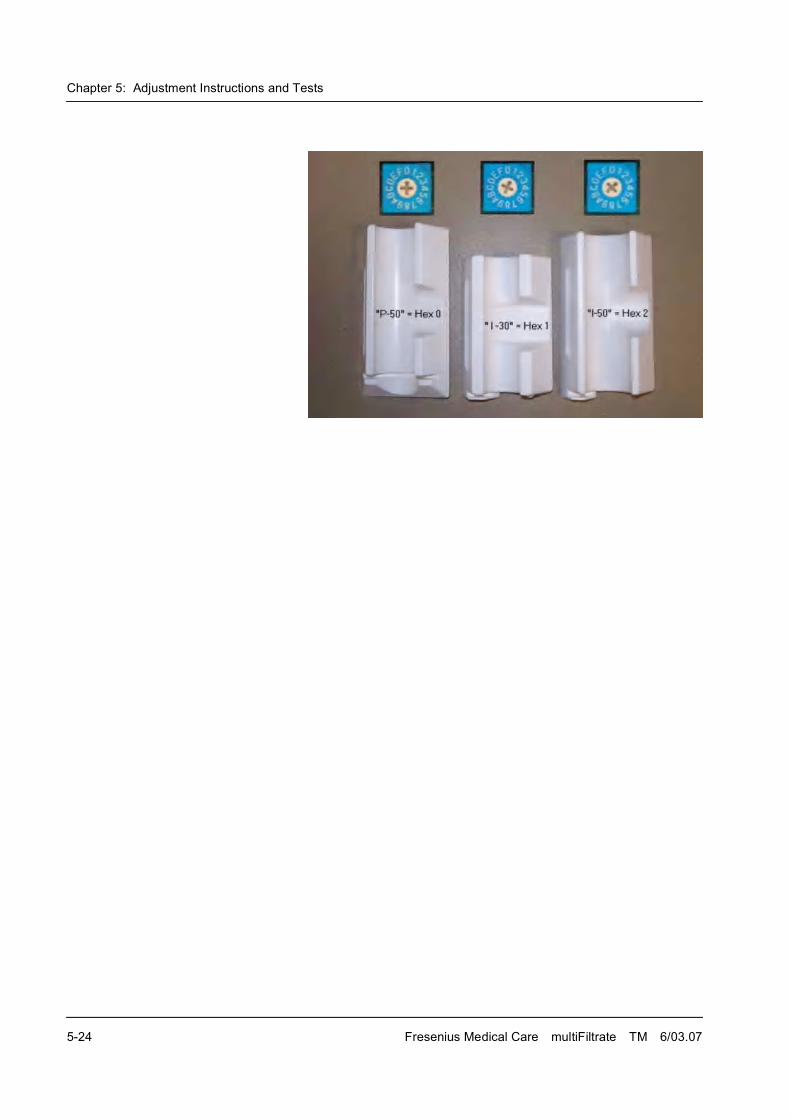
Chapter 5: Adjustment Instructions and Tests
5-24 Fresenius Medical Care multiFiltrate TM 6/03.07
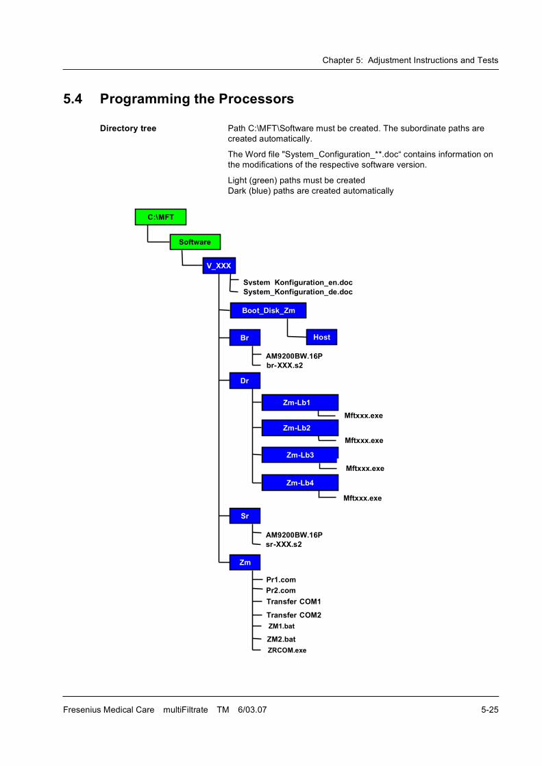
Chapter 5: Adjustment Instructions and Tests
Fresenius Medical Care multiFiltrate TM 6/03.07 5-25
5.4 Programming the Processors
Directory tree Path C:\MFT\Software must be created. The subordinate paths are
created automatically.
The Word file "System_Configuration_**.doc� contains information on
the modifications of the respective software version.
Light (green) paths must be created
Dark (blue) paths are created automatically
������
���� �
�����
�����������
����
�
�
������
������
������
�����
!�"�##�$%�&'
� ����%��
�(((%�(�
�(((%�(�
!�"�##�$%�&'
� ����%��
��
' �%)��
' �%)��
� �*�� �+��
� �*�� �+��
���%��
���%��
�,�+�%�(�
����
��������
�-����.�*�/0 ���*��*%1�)
�-����.�*�/0 ���*�1�%1�)
�(((%�(�
�(((%�(�
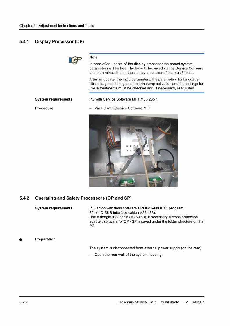
Chapter 5: Adjustment Instructions and Tests
5-26 Fresenius Medical Care multiFiltrate TM 6/03.07
5.4.1 Display Processor (DP)
System requirements PC with Service Software MFT M36 235 1
Procedure � Via PC with Service Software MFT
5.4.2 Operating and Safety Processors (OP and SP)
System requirements PC/laptop with flash software PROG16-68HC16 program,
25-pin D-SUB interface cable (M28 488),
Use a dongle ICD cable (M28 489), if necessary a cross protection
adapter; software for OP / SP is saved under the folder structure on the
PC.
Preparation
The system is disconnected from external power supply (on the rear).
� Open the rear wall of the system housing.
Note
In case of an update of the display processor the preset system
parameters will be lost. The have to be saved via the Service Software
and then reinstalled on the display processor of the multiFiltrate.
After an update, the mDL parameters, the parameters for language,
filtrate bag monitoring and heparin pump activation and the settings for
Ci-Ca treatments must be checked and, if necessary, readjusted.
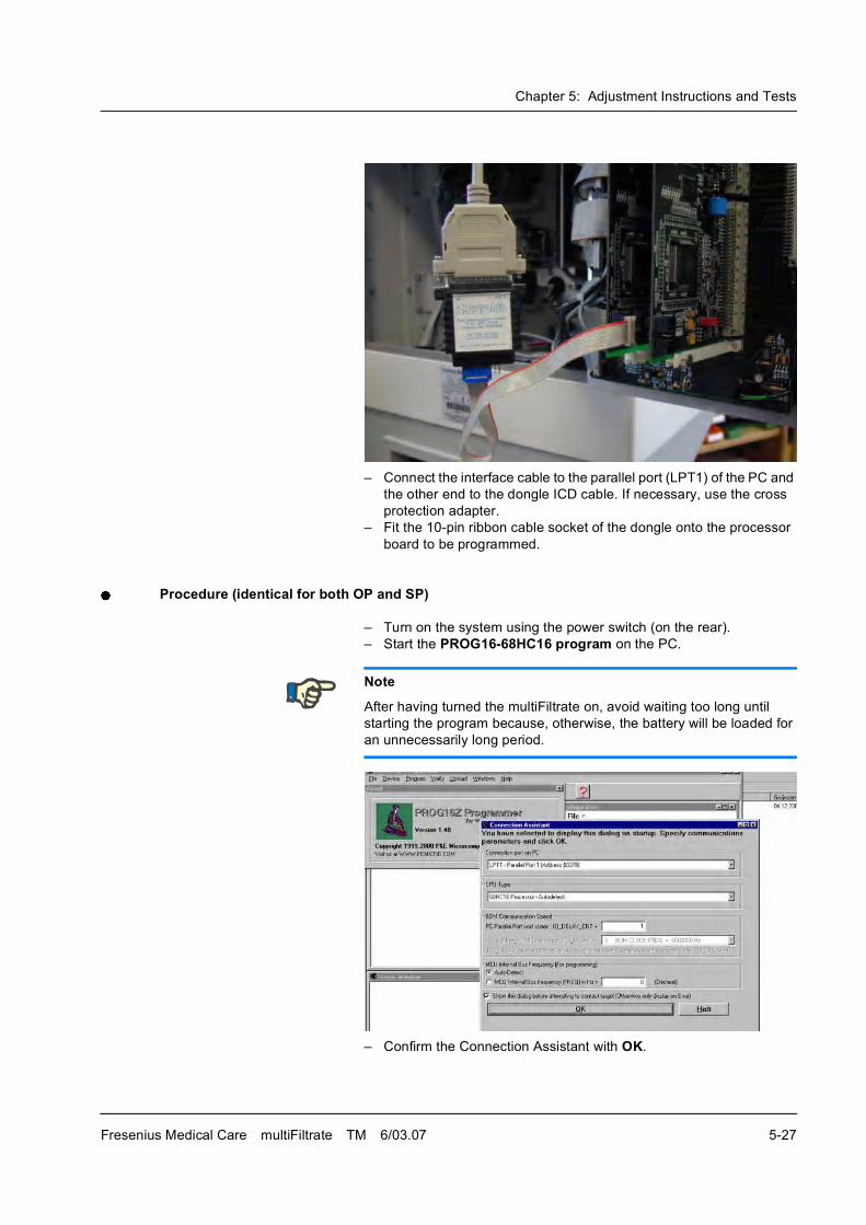
Chapter 5: Adjustment Instructions and Tests
Fresenius Medical Care multiFiltrate TM 6/03.07 5-27
� Connect the interface cable to the parallel port (LPT1) of the PC and
the other end to the dongle ICD cable. If necessary, use the cross
protection adapter.
� Fit the 10-pin ribbon cable socket of the dongle onto the processor
board to be programmed.
Procedure (identical for both OP and SP)
� Turn on the system using the power switch (on the rear).
� Start the PROG16-68HC16 program on the PC.
� Confirm the Connection Assistant with OK.
Note
After having turned the multiFiltrate on, avoid waiting too long until
starting the program because, otherwise, the battery will be loaded for
an unnecessarily long period.
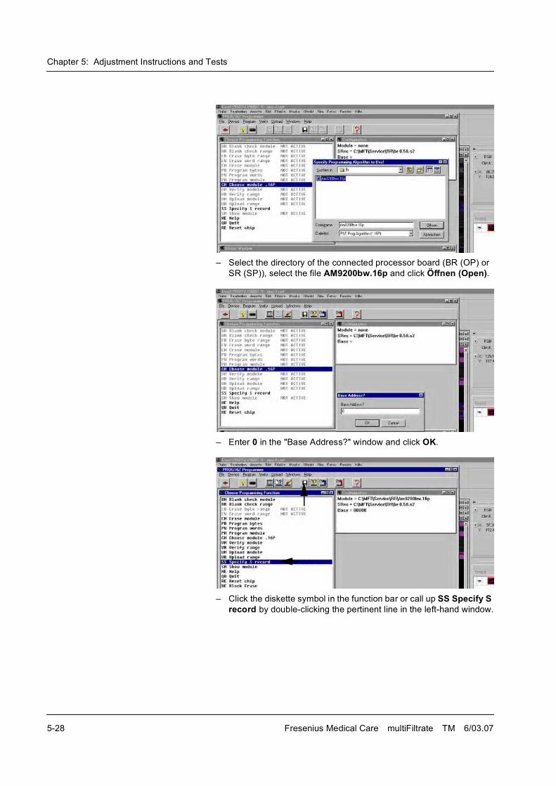
Chapter 5: Adjustment Instructions and Tests
5-28 Fresenius Medical Care multiFiltrate TM 6/03.07
� Select the directory of the connected processor board (BR (OP) or
SR (SP)), select the file AM9200bw.16p and click Öffnen (Open).
� Enter 0 in the "Base Address?" window and click OK.
� Click the diskette symbol in the function bar or call up SS Specify S record by double-clicking the pertinent line in the left-hand window.
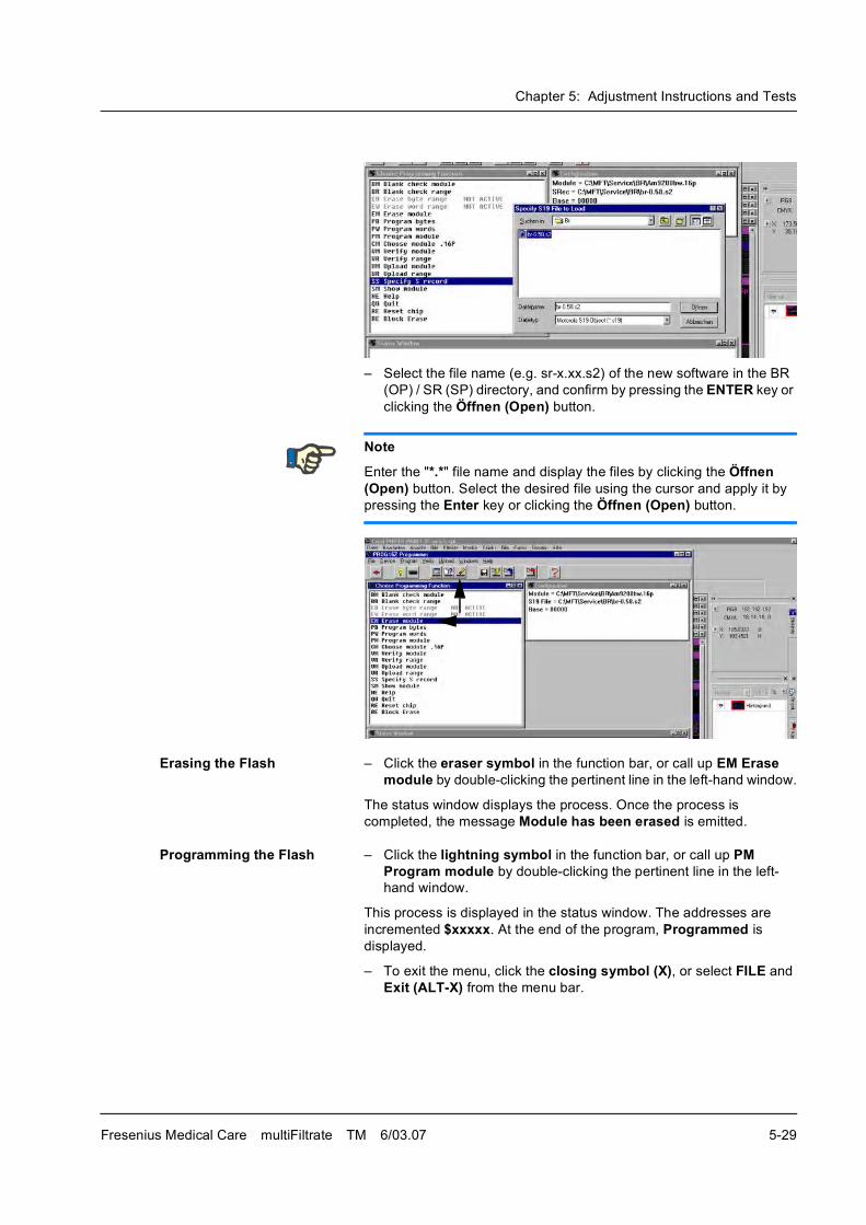
Chapter 5: Adjustment Instructions and Tests
Fresenius Medical Care multiFiltrate TM 6/03.07 5-29
� Select the file name (e.g. sr-x.xx.s2) of the new software in the BR
(OP) / SR (SP) directory, and confirm by pressing the ENTER key or
clicking the Öffnen (Open) button.
Erasing the Flash � Click the eraser symbol in the function bar, or call up EM Erase module by double-clicking the pertinent line in the left-hand window.
The status window displays the process. Once the process is
completed, the message Module has been erased is emitted.
Programming the Flash � Click the lightning symbol in the function bar, or call up PM Program module by double-clicking the pertinent line in the left-
hand window.
This process is displayed in the status window. The addresses are
incremented $xxxxx. At the end of the program, Programmed is
displayed.
� To exit the menu, click the closing symbol (X), or select FILE and
Exit (ALT-X) from the menu bar.
Note
Enter the "*.*" file name and display the files by clicking the Öffnen (Open) button. Select the desired file using the cursor and apply it by
pressing the Enter key or clicking the Öffnen (Open) button.
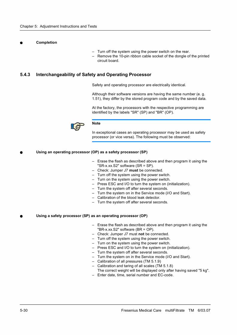
Chapter 5: Adjustment Instructions and Tests
5-30 Fresenius Medical Care multiFiltrate TM 6/03.07
Completion
� Turn off the system using the power switch on the rear.
� Remove the 10-pin ribbon cable socket of the dongle of the printed
circuit board.
5.4.3 Interchangeability of Safety and Operating Processor
Safety and operating processor are electrically identical.
Although their software versions are having the same number (e. g.
1.51), they differ by the stored program code and by the saved data.
At the factory, the processors with the respective programming are
identified by the labels "SR" (SP) and "BR" (OP).
Using an operating processor (OP) as a safety processor (SP)
� Erase the flash as described above and then program it using the
"SR-x.xx.S2" software (SR = SP).
� Check: Jumper J7 must be connected.
� Turn off the system using the power switch.
� Turn on the system using the power switch.
� Press ESC and I/O to turn the system on (initialization).
� Turn the system off after several seconds.
� Turn the system on in the Service mode (I/O and Start).
� Calibration of the blood leak detector.
� Turn the system off after several seconds.
Using a safety processor (SP) as an operating processor (OP)
� Erase the flash as described above and then program it using the
"BR-x.xx.S2" software (BR = OP).
� Check: Jumper J7 must not be connected.
� Turn off the system using the power switch.
� Turn on the system using the power switch.
� Press ESC and I/O to turn the system on (initialization).
� Turn the system off after several seconds.
� Turn the system on in the Service mode (I/O and Start).
� Calibration of all pressures (TM 5.1.9)
� Calibration and taring of all scales (TM 5.1.8)
The correct weight will be displayed only after having saved "5 kg".
� Enter date, time, serial number and EC-code.
Note
In exceptional cases an operating processor may be used as safety
processor (or vice versa). The following must be observed:
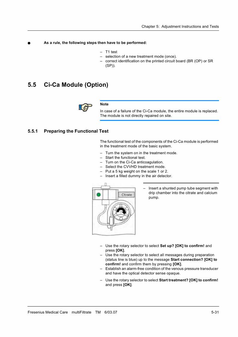
Chapter 5: Adjustment Instructions and Tests
Fresenius Medical Care multiFiltrate TM 6/03.07 5-31
As a rule, the following steps then have to be performed:
� T1 test
� selection of a new treatment mode (once).
� correct identification on the printed circuit board (BR (OP) or SR
(SP)).
5.5 Ci-Ca Module (Option)
5.5.1 Preparing the Functional Test
The functional test of the components of the Ci-Ca module is performed
in the treatment mode of the basic system.
� Turn the system on in the treatment mode.
� Start the functional test.
� Turn on the Ci-Ca anticoagulation.
� Select the CVVHD treatment mode.
� Put a 5 kg weight on the scale 1 or 2.
� Insert a filled dummy in the air detector.
� Use the rotary selector to select Set up? [OK] to confirm! and
press [OK].� Use the rotary selector to select all messages during preparation
(status line is blue) up to the message Start connection? [OK] to confirm! and confirm them by pressing [OK].
� Establish an alarm-free condition of the venous pressure transducer
and have the optical detector sense opaque.
� Use the rotary selector to select Start treatment? [OK] to confirm! and press [OK].
Note
In case of a failure of the Ci-Ca module, the entire module is replaced.
The module is not directly repaired on site.
� Insert a shunted pump tube segment with
drip chamber into the citrate and calcium
pump.
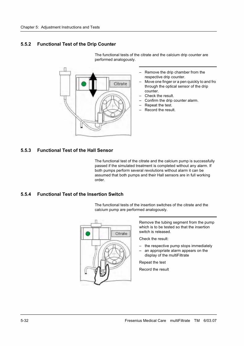
Chapter 5: Adjustment Instructions and Tests
5-32 Fresenius Medical Care multiFiltrate TM 6/03.07
5.5.2 Functional Test of the Drip Counter
The functional tests of the citrate and the calcium drip counter are
performed analogously.
5.5.3 Functional Test of the Hall Sensor
The functional test of the citrate and the calcium pump is successfully
passed if the simulated treatment is completed without any alarm. If
both pumps perform several revolutions without alarm it can be
assumed that both pumps and their Hall sensors are in full working
order.
5.5.4 Functional Test of the Insertion Switch
The functional tests of the insertion switches of the citrate and the
calcium pump are performed analogously.
� Remove the drip chamber from the
respective drip counter.
� Move one finger or a pen quickly to and fro
through the optical sensor of the drip
counter.
� Check the result.
� Confirm the drip counter alarm.
� Repeat the test.
� Record the result.
Remove the tubing segment from the pump
which is to be tested so that the insertion
switch is released.
Check the result:
� the respective pump stops immediately
� an appropriate alarm appears on the
display of the multiFiltrate
Repeat the test
Record the result
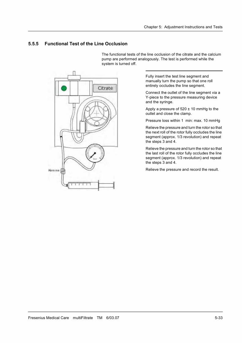
Chapter 5: Adjustment Instructions and Tests
Fresenius Medical Care multiFiltrate TM 6/03.07 5-33
5.5.5 Functional Test of the Line Occlusion
The functional tests of the line occlusion of the citrate and the calcium
pump are performed analogously. The test is performed while the
system is turned off.
Fully insert the test line segment and
manually turn the pump so that one roll
entirely occludes the line segment.
Connect the outlet of the line segment via a
Y-piece to the pressure measuring device
and the syringe.
Apply a pressure of 520 ± 10 mmHg to the
outlet and close the clamp.
Pressure loss within 1 min: max. 10 mmHg
Relieve the pressure and turn the rotor so that
the next roll of the rotor fully occludes the line
segment (approx. 1/3 revolution) and repeat
the steps 3 and 4.
Relieve the pressure and turn the rotor so that
the last roll of the rotor fully occludes the line
segment (approx. 1/3 revolution) and repeat
the steps 3 and 4.
Relieve the pressure and record the result.

Chapter 5: Adjustment Instructions and Tests
5-34 Fresenius Medical Care multiFiltrate TM 6/03.07
Chapter 6: PC Service Software MFT
Fresenius Medical Care multiFiltrate TM 6/03.07 6-1
6 PC Service Software MFT
6.1 Organization of the Quick Guide
Editorial information The Quick Guide is available as a separate document. It is subject to an
own updating cycle and is revised independently from the Technical
Manual. It may be enclosed to chapter 6.
6.2 General Information
6.3 Preparation
6.3.1 System Requirements
� PC with at least 10 MByte of free hard disk space
� Microsoft Windows 98, ME, 2000 or XP
� 32 MByte RAM
� 1 CD-ROM drive
� 1 free USB port (for SmartCardReader)
� 1 free RS232 interface (for communication with the Multifiltrate)
Caution
After each transmission of data from the service program to the dialysis
system, the operator of the service program must check the data at the
dialysis system for plausibility. The operator himself or herself is
responsible for the correctness of the data.
Caution
After each transmission of data from the service program to the dialysis
system, the dialysis system must be switched off and on again before a
patient treatment is started.
Caution
This service program is only intended for service purposes. Ensure that
the interface cable to the PC is not connected during patient treatment.
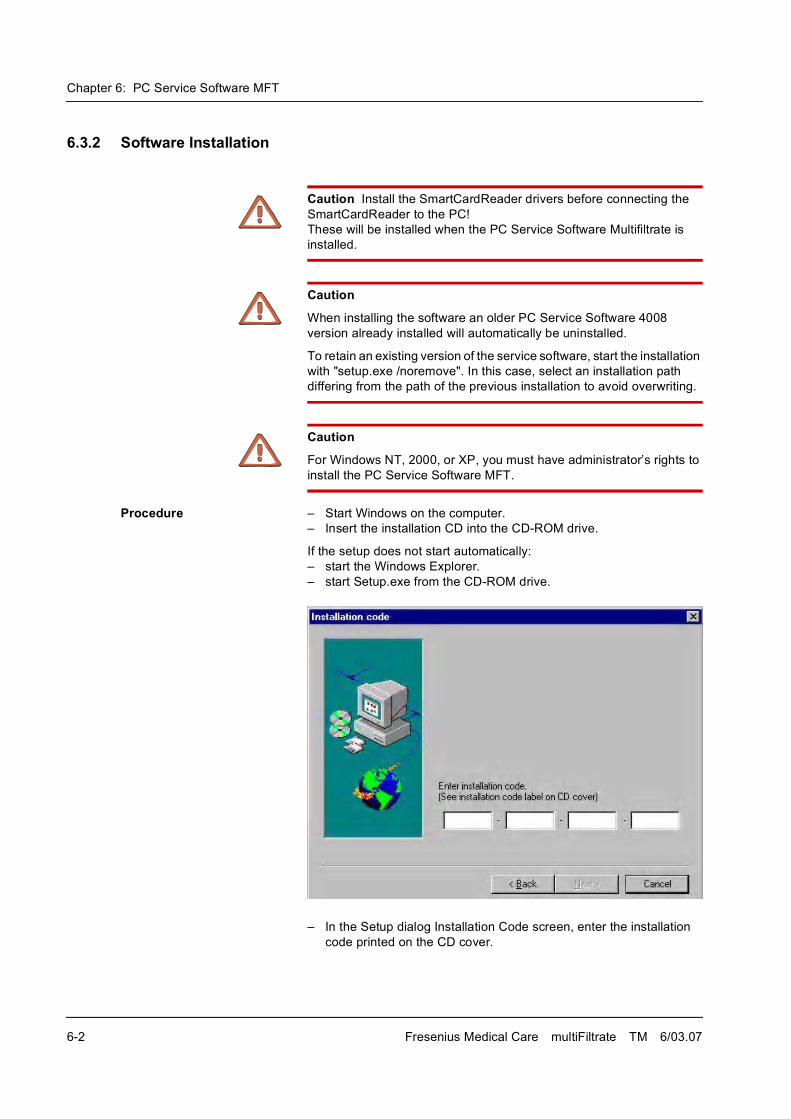
Chapter 6: PC Service Software MFT
6-2 Fresenius Medical Care multiFiltrate TM 6/03.07
6.3.2 Software Installation
Procedure � Start Windows on the computer.
� Insert the installation CD into the CD-ROM drive.
If the setup does not start automatically:
� start the Windows Explorer.
� start Setup.exe from the CD-ROM drive.
� In the Setup dialog Installation Code screen, enter the installation
code printed on the CD cover.
Caution Install the SmartCardReader drivers before connecting the
SmartCardReader to the PC!
These will be installed when the PC Service Software Multifiltrate is
installed.
Caution
When installing the software an older PC Service Software 4008
version already installed will automatically be uninstalled.
To retain an existing version of the service software, start the installation
with "setup.exe /noremove". In this case, select an installation path
differing from the path of the previous installation to avoid overwriting.
Caution
For Windows NT, 2000, or XP, you must have administrator�s rights to
install the PC Service Software MFT.
Chapter 6: PC Service Software MFT
Fresenius Medical Care multiFiltrate TM 6/03.07 6-3
When installing the SmartCard Reader driver under Windows XP a
message may be displayed informing you that the drivers failed to pass
the Windows Logo test.
� The software will be installed after clicking the "Continue Anyway"
button and then the "Finish" button.
The software installation is complete.
6.3.3 Hardware Installation
Connect the PC and the Multifiltrate via the supplied interface cable.
Connect the SmartCard Reader to a vacant USB port.
6.3.4 ServiceCard Description
The use of the PC Service Software Multifiltrate requires an appropriate
authorization. The PC Service Software Multifiltrate and the respective
ServiceCard will check your authorization.
The ServiceCard is read out via the SmartCard Reader.
� Connect the SmartCard Reader to a vacant USB port.
� Insert the ServiceCard into the SmartCard Reader.
The ServiceCard will be checked when starting the application and
while working with the software. If the card is not inserted or if it is
removed, an error message will be displayed.
Since the authorization is limited to a specific period of time, the
expiration date of the ServiceCard is checked by an operating time
monitoring function. Once this date is exceeded, the PC Service
Software Multifiltrate can no longer be accessed. In this case, the
expiration date must be adapted by an authorized body.
6.3.5 Starting the Software
The software can be started by selecting Start->All Programs-
>Fresenius->Service MFT->Service MFT.
Caution
This is not a standard cable. It is therefore imperative to use the
enclosed interface cable.
Caution
Install the SmartCardReader drivers before connecting the
SmartCardReader to the PC!
These will be installed when the PC Service Software Multifiltrate is
installed.

Chapter 6: PC Service Software MFT
6-4 Fresenius Medical Care multiFiltrate TM 6/03.07

Chapter 7: Block Diagrams and Component Layouts
Fresenius Medical Care multiFiltrate TM 6/03.07 7-1
7 Block Diagrams and Component Layouts
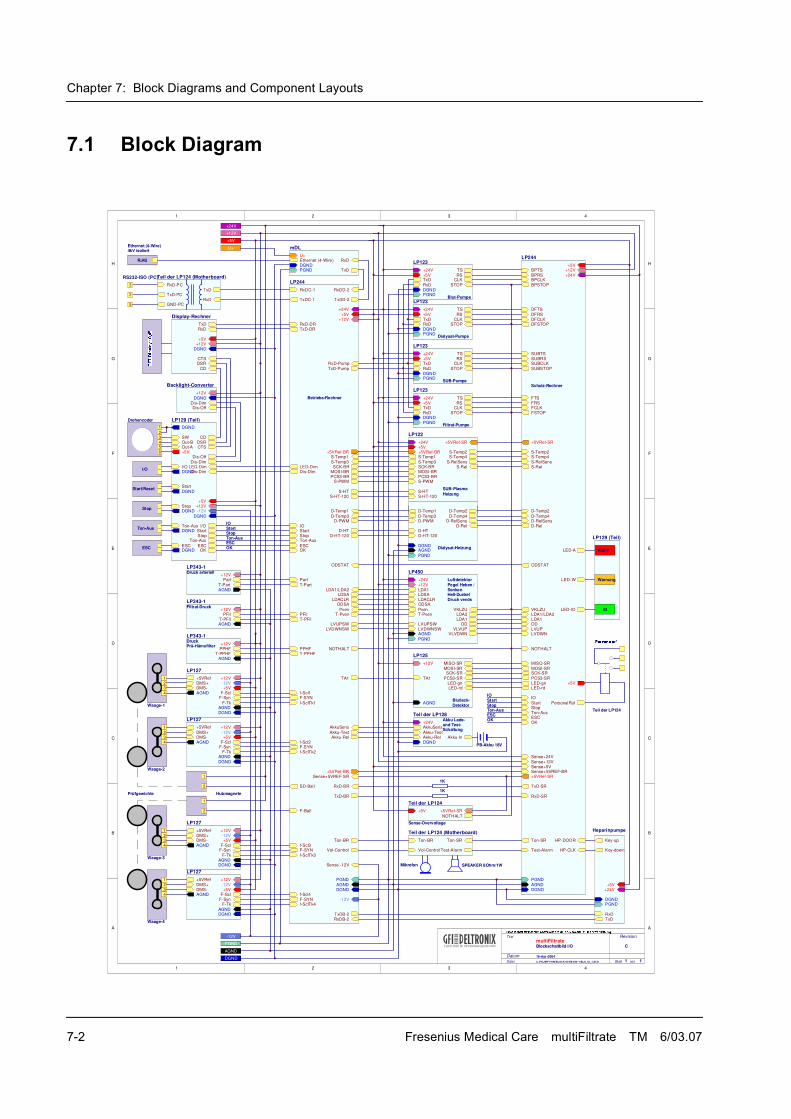
Chapter 7: Block Diagrams and Component Layouts
7-2 Fresenius Medical Care multiFiltrate TM 6/03.07
7.1 Block Diagram
1 2 3 4
A
B
C
D
E
F
G
H
4321
H
G
F
E
D
C
B
A
LP129 (Teil)
TS
RSCLK
STOPTxDRxD
+24V
+5V
DGNDPGND
LP123
C:\PRJ\MFT\HW\BLOCK-IO\REVISI~1\BLK_IO_3.SCH 1 116-Apr-2004
Blockschaltbild I/O C
Titel Revision
Datum
Datei Blatt von
S-Temp3
S-Temp1
SCK-BR
S-PWM
D-Temp3
D-Temp1
D-PWM
TxD-Pump
RxD-Pump
LDA1/LDA2LDSA
LDACLRODSA
PvenT-Pven
LVUPSW
TA1
AkkuSens
Akku-TestAkku-Rel
RxD-BR
TxD-BR
RxD-DRTxD-DR
IO
Ton-Aus
Part
T-Part
PFilT-PFil
PPHFT-PPHF
RxDC-1
TxDC-1
+24V
+5V
DGND
PGND
+5VRef-BR
AGND
+12V
Start
Sense+5VREF-SR+5VRef-BR
Stop
f-SclTk1
f-Scl1
f-Scl2
SD-Ball
F-Ball
f-Scl3
f-Scl4
OK
MOSI-BRPCS3-BR
F-SYN
f-SclTk3
F-SYN
F-SYN
F-SYNf-SclTk2
ESC
Dis-DimLED-Dim
Ton-BR
ODSTAT
LVDWNSW
S-HTS-HT-120
D-HT-120D-HT
Vol-Control
-12V
Sense -12V
NOTHALT
f-SclTk4
TxDB-2RxDB-2
TxDD-2
RxDD-2
LP244
BPTS
BPRSBPCLK
BPSTOP
DFTS
DFRSDFCLKDFSTOP
SUBTSSUBRSSUBCLK
SUBSTOP
FTSFRSFCLKFSTOP
S-Temp2
S-RelSensS-Rel
D-Temp2
D-RelSensD-Rel
D-Temp4
LDA1/LDA2
ODLVUPLVDWN
MISO-SR
TxD-SR
RxD-SR
+5VRef-SRSense+5VREF-BRSense+5VSense+12V
Sense+24V
PGND
AGNDDGND
+24V
+12V+5V
LED-A
LED-W
LED-IO
+5V
PersonalRuf
S-Temp4
OK
VKLZU
ODSTAT
+5VRef-SR
SCK-SR
PCS3-SRLED-gnLED-rd
MOSI-SR
Ton-SR
Test-Alarm
ESCTon-AusStopStart
IO
NOTHALT
HP-CLK
HP-DOOR
LDA1
LP244
TS
RSCLK
STOP
TxD
RxD
+24V
+5V
DGNDPGND
LP123
TSRS
CLKSTOP
TxDRxD
+24V+5V
DGNDPGND
LP123
TSRS
CLK
STOPRxD
TxD
+24V+5V
DGNDPGND
LP123
S-Temp3
S-Temp1
SCK-BR
S-PWM
S-HT
S-RelS-RelSens
S-Temp2
+24V+5V+5VRef-BR
S-Temp4
MOSI-BRPCS3-BR
+5VRef-SR
S-HT-120
LP122
D-Temp2
D-RelSensD-Rel
D-HT
D-PWM
D-Temp1
D-Temp3
DGNDAGND
PGND
D-Temp4
D-HT-120
T-Pven
LDA1LDSA
LDA2
ODVLVUP
VLVDWN
VKLZU
LDACLRODSA
Pven
LVUPSW
+24V
+12V
AGND
PGND
LVDWNSW
LDA1
LP450
TA1
MISO-SR+12V
AGND
MOSI-SRSCK-SR
PCS3-SRLED-gnLED-rd
LP125
AkkuSens
Akku-TestAkku-RelDGND
+24V
Akku-In
Teil der LP128
RxDTxD
CTSDSR
CD
+5V+12V
DGND
Display-Rechner
1
23456
Drehencoder
I/O
Part
T-Part
+12V
AGND
LP343-1
PFilT-PFil
+12V
AGND
LP343-1
T-PPHFPPHF
AGND
+12V
LP343-1
1
1234
1
234
2
1234
1
2
1
234
TxD
RxDTxD-PC
RxD-PC
GND-PC
Teil der LP124 (Motherboard)
SPEAKER 8Ohm/1W
Prüfgewichte
Waage-1
Waage-2
Waage-4
Waage-3
Hubmagnete
+24V
+5V
+12V
multiFiltrate
PB-Akku 18V
PGND
AGND
DGND
3
2
Start/Reset
Druck arteriell
Filtrat-Druck
Druck
Blut-Pumpe
Dialysat-Pumpe
SUB-Pumpe
Filtrat-Pumpe
SUB-Plasma
Dialysat-Heizung
Luftdetektor
Druck venösHell-Dunkel
Pegel Heben /
Blutleck-
Akku Lade-und Test-
Detektor
Schaltung
Senken
Stop
Prä-Hämofilter
Betriebs-Rechner
Schutz-Rechner
+5VRefDMS+DMS-AGND
AGND
F-Scl
-12V+12V
DGND
F-Syn
F-Tk
+5V
LP127
+5VRef
DMS+DMS-AGND
AGND
F-Scl
-12V
+12V
DGND
+5V
F-SynF-Tk
LP127
+5VRefDMS+DMS-AGND
AGND
F-Scl
-12V+12V
DGND
+5V
F-Syn
F-Tk
LP127
+5VRef
DMS+DMS-AGND
AGND
F-Scl
-12V
+12V
DGND
F-TkF-Syn
+5V
LP127
5
Warnung
IO
1K
1K
ESC
Ton-Aus
Ton-BR
Vol-Control Test-Alarm
Ton-SR
Teil der LP124 (Motherboard)
Mikrofon
-12V
+5VRef-SR
NOTHALT
+5V
Teil der LP124
Sense-Overvoltage
Heizung
IOStartStopTon-AusESCOK
RS232-ISO (PC)
CTSDSR
CD
+12V
DGND
+5V
Dis-Dim
Dis-Off
-12V
I/ODGND
Start
DGND
StopDGND
Ton-AusDGND
ESCDGND
I/OStartStop
Ton-Aus
ESCOK
DGND
SWOut-BOut-A+5V
LED-DimDis-Dim
LP129 (Teil)
Alarm
+12V
Dis-DimDGND
Dis-Off
Backlight-Converter
IOStartStopTon-AusESCOK
TxDRxD
PGNDDGND
Key-down
Key-up
+24V+5V
Heparinpumpe
PGNDDGNDEthernet (4-Wire)U+
TxD
RxD
mDLU+
RJ45
Ethernet (4-Wire)4kV isoliert
Teil der LP124
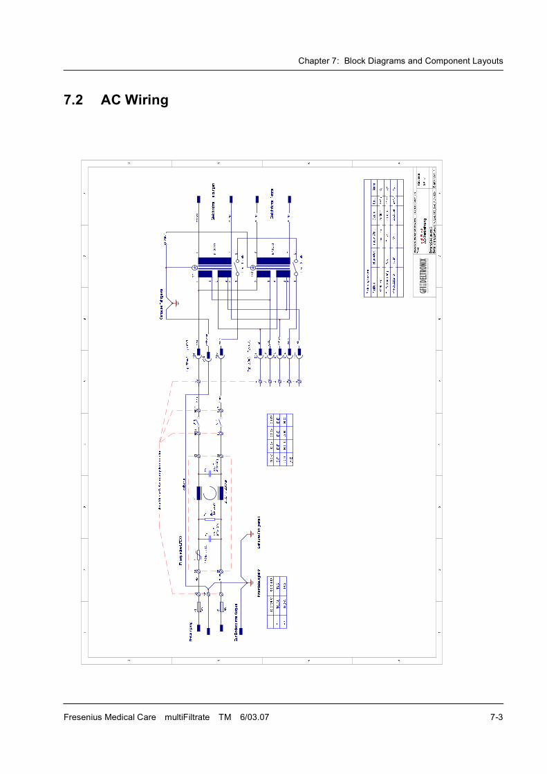
Chapter 7: Block Diagrams and Component Layouts
Fresenius Medical Care multiFiltrate TM 6/03.07 7-3
7.2 AC Wiring
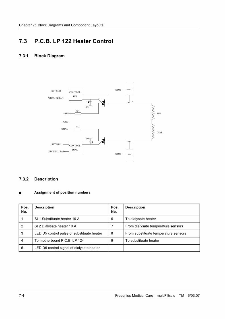
Chapter 7: Block Diagrams and Component Layouts
7-4 Fresenius Medical Care multiFiltrate TM 6/03.07
7.3 P.C.B. LP 122 Heater Control
7.3.1 Block Diagram
7.3.2 Description
Assignment of position numbers
�������
���������
����
�
����
� ��
���
���
����
�������
���
�������
��
���
��
���� ��
���� ����
�
�
Pos.No.
Description Pos. No.
Description
1 SI 1 Substituate heater 10 A 6 To dialysate heater
2 SI 2 Dialysate heater 10 A 7 From dialysate temperature sensors
3 LED D5 control pulse of substituate heater 8 From substituate temperature sensors
4 To motherboard P.C.B. LP 124 9 To substituate heater
5 LED D6 control signal of dialysate heater
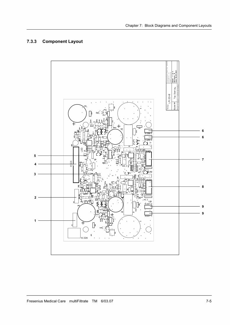
Chapter 7: Block Diagrams and Component Layouts
Fresenius Medical Care multiFiltrate TM 6/03.07 7-5
7.3.3 Component Layout
3
6
1
4
5
2
6
7
8
9
9
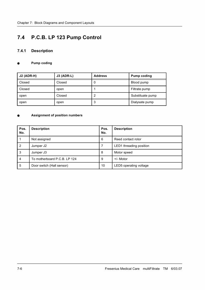
Chapter 7: Block Diagrams and Component Layouts
7-6 Fresenius Medical Care multiFiltrate TM 6/03.07
7.4 P.C.B. LP 123 Pump Control
7.4.1 Description
Pump coding
Assignment of position numbers
J2 (ADR-H) J3 (ADR-L) Address Pump coding
Closed Closed 0 Blood pump
Closed open 1 Filtrate pump
open Closed 2 Substituate pump
open open 3 Dialysate pump
Pos. No.
Description Pos. No.
Description
1 Not assigned 6 Reed contact rotor
2 Jumper J2 7 LED1 threading position
3 Jumper J3 8 Motor speed
4 To motherboard P.C.B. LP 124 9 +/- Motor
5 Door switch (Hall sensor) 10 LED5 operating voltage
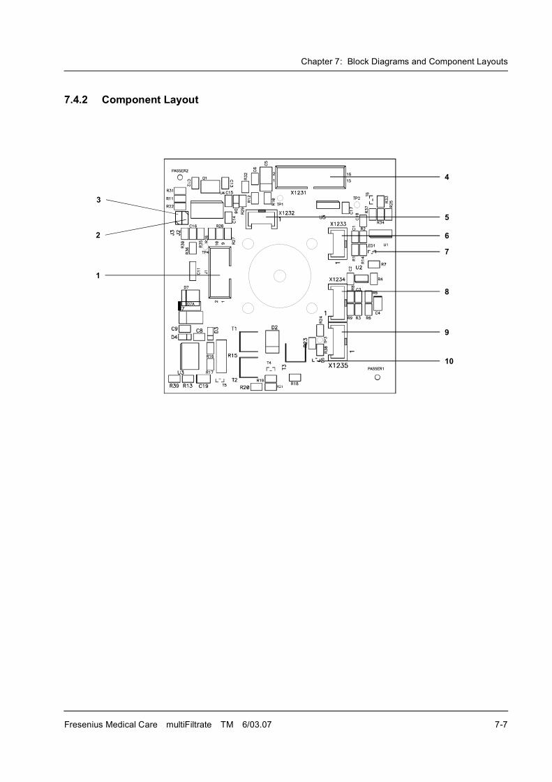
Chapter 7: Block Diagrams and Component Layouts
Fresenius Medical Care multiFiltrate TM 6/03.07 7-7
7.4.2 Component Layout
3
4
2
1
5
6
7
8
10
9
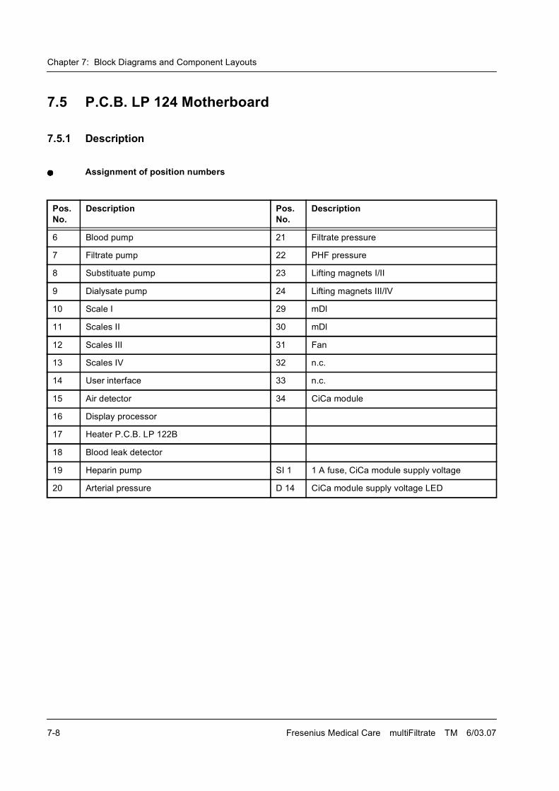
Chapter 7: Block Diagrams and Component Layouts
7-8 Fresenius Medical Care multiFiltrate TM 6/03.07
7.5 P.C.B. LP 124 Motherboard
7.5.1 Description
Assignment of position numbers
Pos. No.
Description Pos. No.
Description
6 Blood pump 21 Filtrate pressure
7 Filtrate pump 22 PHF pressure
8 Substituate pump 23 Lifting magnets I/II
9 Dialysate pump 24 Lifting magnets III/IV
10 Scale I 29 mDl
11 Scales II 30 mDl
12 Scales III 31 Fan
13 Scales IV 32 n.c.
14 User interface 33 n.c.
15 Air detector 34 CiCa module
16 Display processor
17 Heater P.C.B. LP 122B
18 Blood leak detector
19 Heparin pump SI 1 1 A fuse, CiCa module supply voltage
20 Arterial pressure D 14 CiCa module supply voltage LED
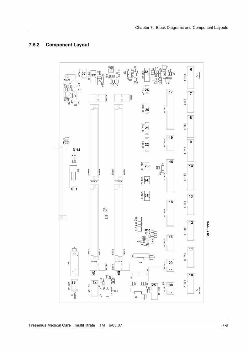
Chapter 7: Block Diagrams and Component Layouts
Fresenius Medical Care multiFiltrate TM 6/03.07 7-9
7.5.2 Component Layout
6
7
8
9
14
12
13
11
10
29
30
16
18
15
17
19
32
26
20
21
22
23
24
31
2528
3327
34
SI 1
D 14
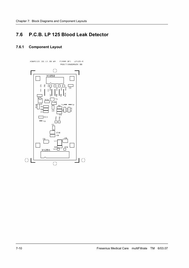
Chapter 7: Block Diagrams and Component Layouts
7-10 Fresenius Medical Care multiFiltrate TM 6/03.07
7.6 P.C.B. LP 125 Blood Leak Detector
7.6.1 Component Layout
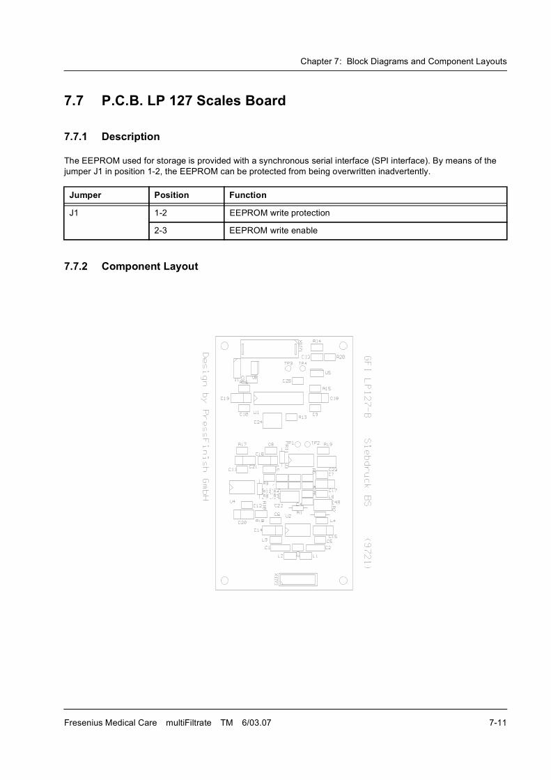
Chapter 7: Block Diagrams and Component Layouts
Fresenius Medical Care multiFiltrate TM 6/03.07 7-11
7.7 P.C.B. LP 127 Scales Board
7.7.1 Description
The EEPROM used for storage is provided with a synchronous serial interface (SPI interface). By means of the
jumper J1 in position 1-2, the EEPROM can be protected from being overwritten inadvertently.
7.7.2 Component Layout
Jumper Position Function
J1 1-2 EEPROM write protection
2-3 EEPROM write enable
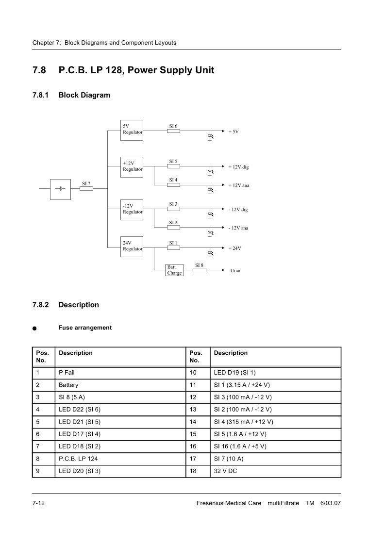
Chapter 7: Block Diagrams and Component Layouts
7-12 Fresenius Medical Care multiFiltrate TM 6/03.07
7.8 P.C.B. LP 128, Power Supply Unit
7.8.1 Block Diagram
7.8.2 Description
Fuse arrangement
���
���������
�����
���������
�����
���������
� ��
���������
��������
����� !"�
� ��� !"�
����
���
���#
����
����
���$
���%����
�&����
����� �'�
� ��� �'�
��� �
�����
Pos. No.
Description Pos. No.
Description
1 P Fail 10 LED D19 (SI 1)
2 Battery 11 SI 1 (3.15 A / +24 V)
3 SI 8 (5 A) 12 SI 3 (100 mA / -12 V)
4 LED D22 (SI 6) 13 SI 2 (100 mA / -12 V)
5 LED D21 (SI 5) 14 SI 4 (315 mA / +12 V)
6 LED D17 (SI 4) 15 SI 5 (1.6 A / +12 V)
7 LED D18 (SI 2) 16 SI 16 (1.6 A / +5 V)
8 P.C.B. LP 124 17 SI 7 (10 A)
9 LED D20 (SI 3) 18 32 V DC
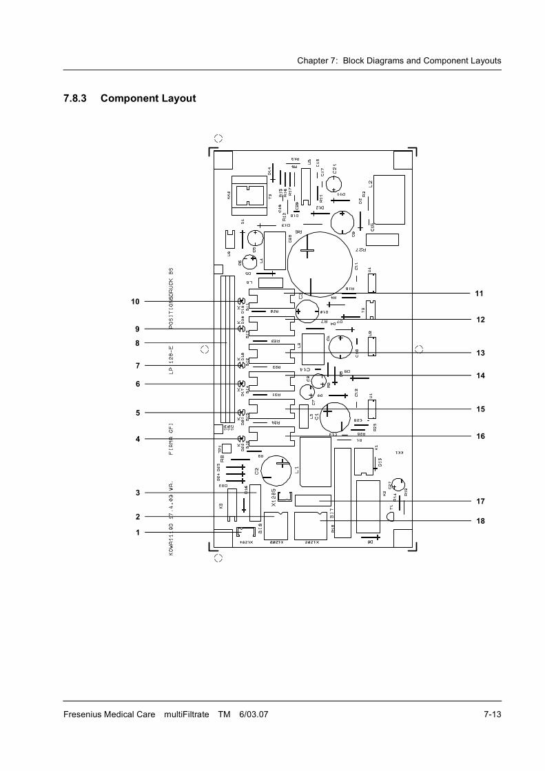
Chapter 7: Block Diagrams and Component Layouts
Fresenius Medical Care multiFiltrate TM 6/03.07 7-13
7.8.3 Component Layout
8
11
7
6
5
4
3
2
1
12
13
14
15
16
17
18
9
10
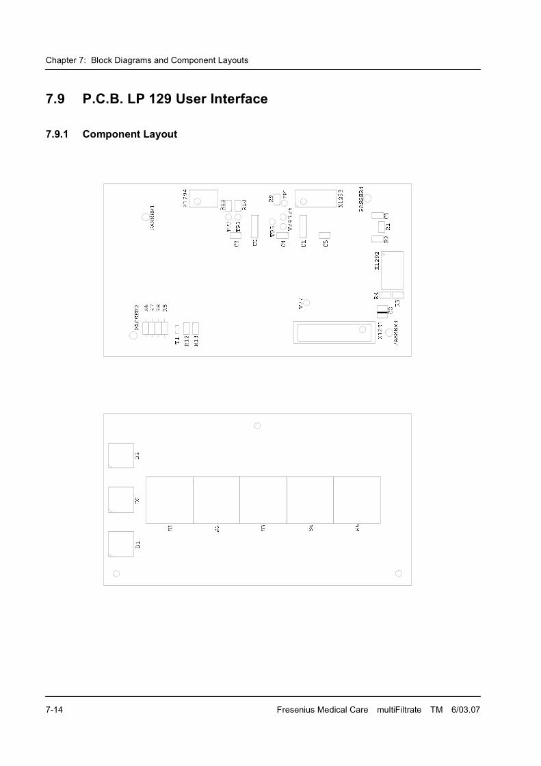
Chapter 7: Block Diagrams and Component Layouts
7-14 Fresenius Medical Care multiFiltrate TM 6/03.07
7.9 P.C.B. LP 129 User Interface
7.9.1 Component Layout
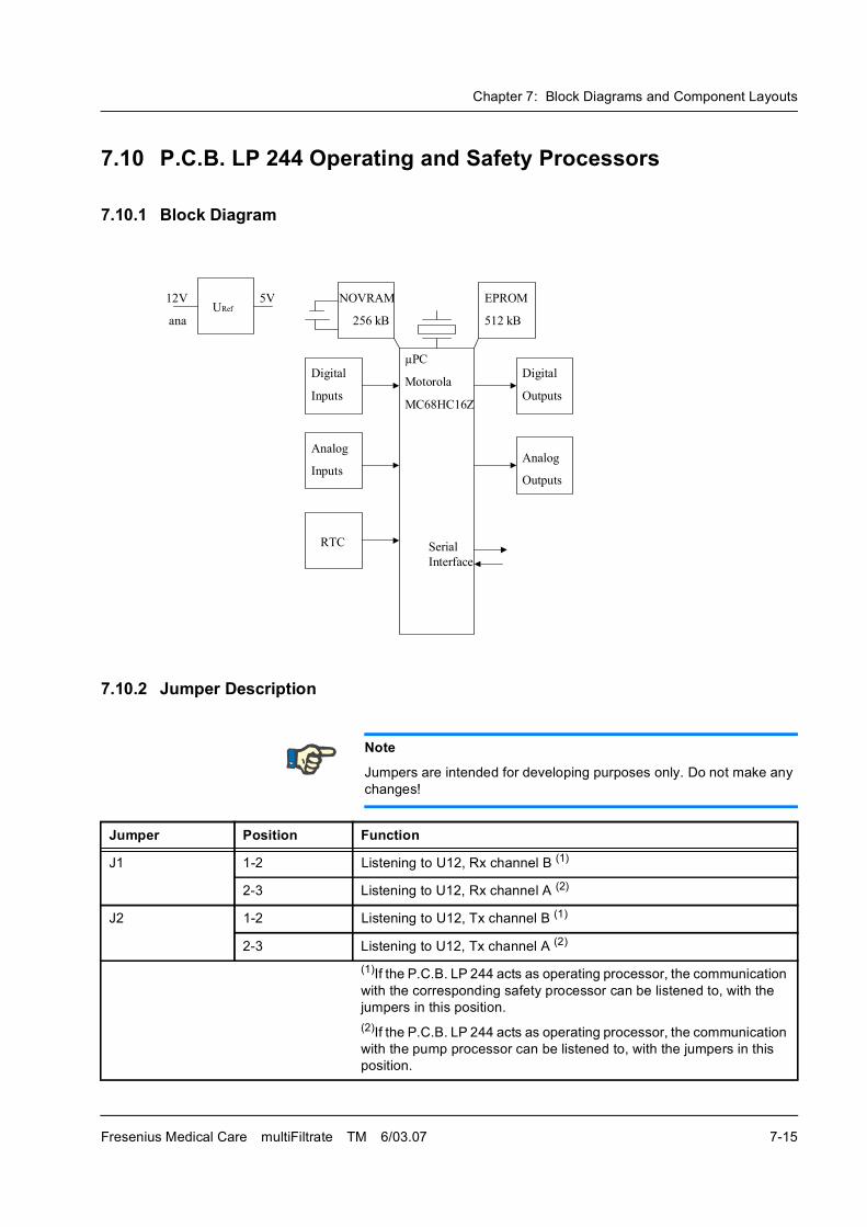
Chapter 7: Block Diagrams and Component Layouts
Fresenius Medical Care multiFiltrate TM 6/03.07 7-15
7.10 P.C.B. LP 244 Operating and Safety Processors
7.10.1 Block Diagram
7.10.2 Jumper Description
Note
Jumpers are intended for developing purposes only. Do not make any
changes!
Jumper Position Function
J1 1-2 Listening to U12, Rx channel B (1)
2-3 Listening to U12, Rx channel A (2)
J2 1-2 Listening to U12, Tx channel B (1)
2-3 Listening to U12, Tx channel A (2)
(1)If the P.C.B. LP 244 acts as operating processor, the communication
with the corresponding safety processor can be listened to, with the
jumpers in this position.
(2)If the P.C.B. LP 244 acts as operating processor, the communication
with the pump processor can be listened to, with the jumpers in this
position.
"�"���
���(��)
'����
���(��)
"�"���
�'(��)
'����
�'(��)
���
����*
����+�
����*
����+�
���"���
�'���,�-�
.��
*�������
*��%/���0
���,
�����
�'�
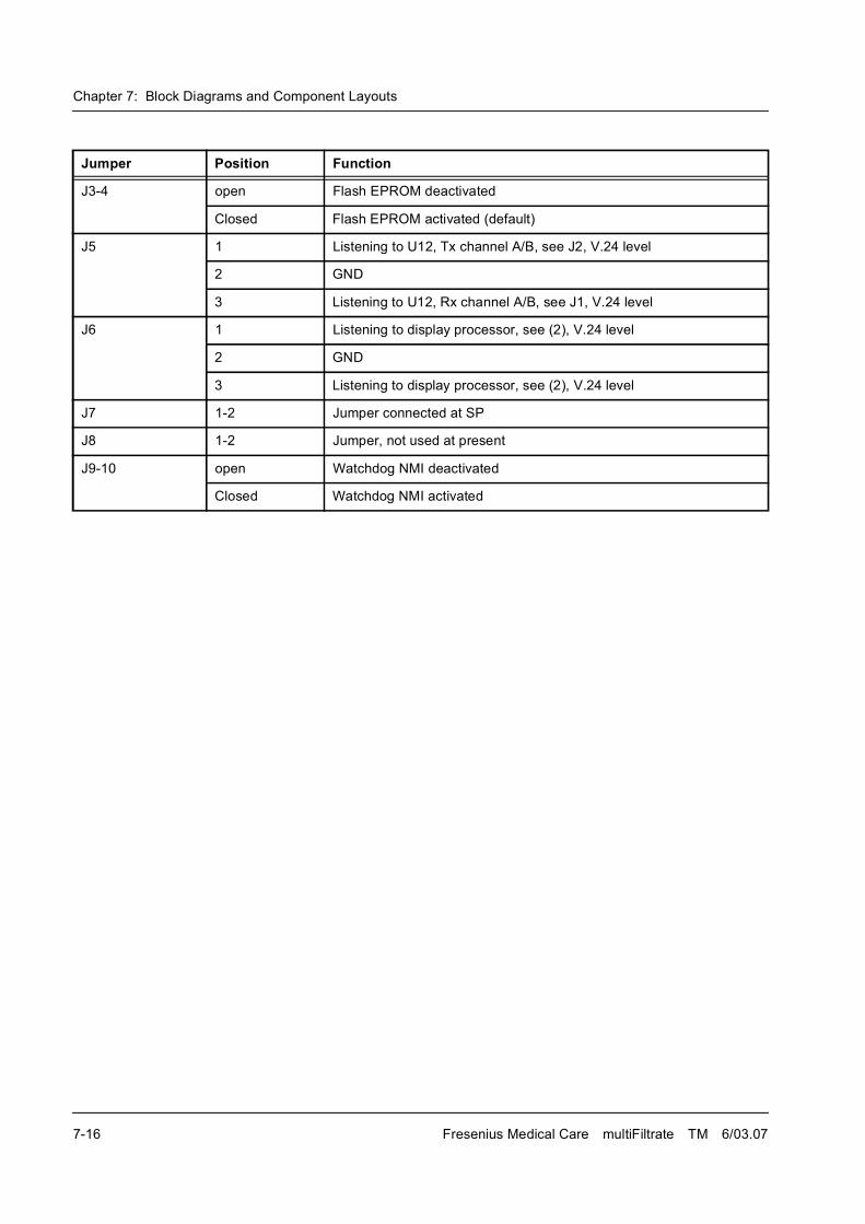
Chapter 7: Block Diagrams and Component Layouts
7-16 Fresenius Medical Care multiFiltrate TM 6/03.07
J3-4 open Flash EPROM deactivated
Closed Flash EPROM activated (default)
J5 1 Listening to U12, Tx channel A/B, see J2, V.24 level
2 GND
3 Listening to U12, Rx channel A/B, see J1, V.24 level
J6 1 Listening to display processor, see (2), V.24 level
2 GND
3 Listening to display processor, see (2), V.24 level
J7 1-2 Jumper connected at SP
J8 1-2 Jumper, not used at present
J9-10 open Watchdog NMI deactivated
Closed Watchdog NMI activated
Jumper Position Function
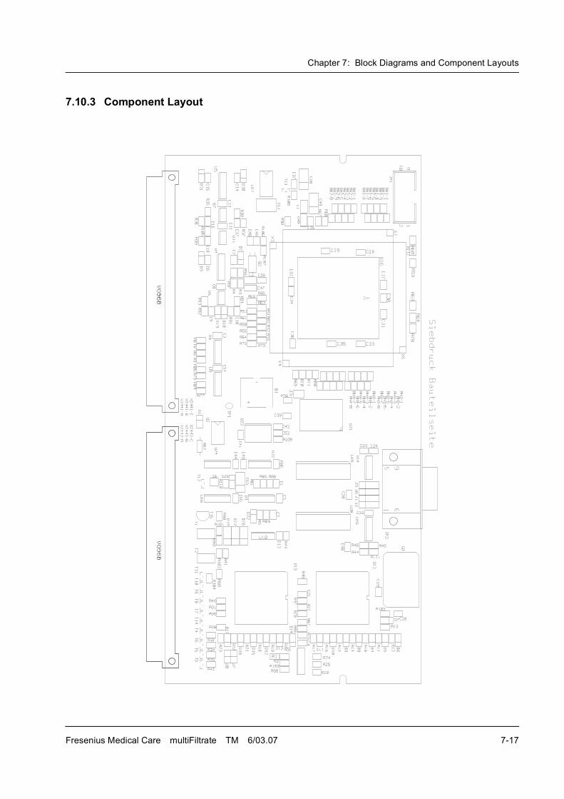
Chapter 7: Block Diagrams and Component Layouts
Fresenius Medical Care multiFiltrate TM 6/03.07 7-17
7.10.3 Component Layout
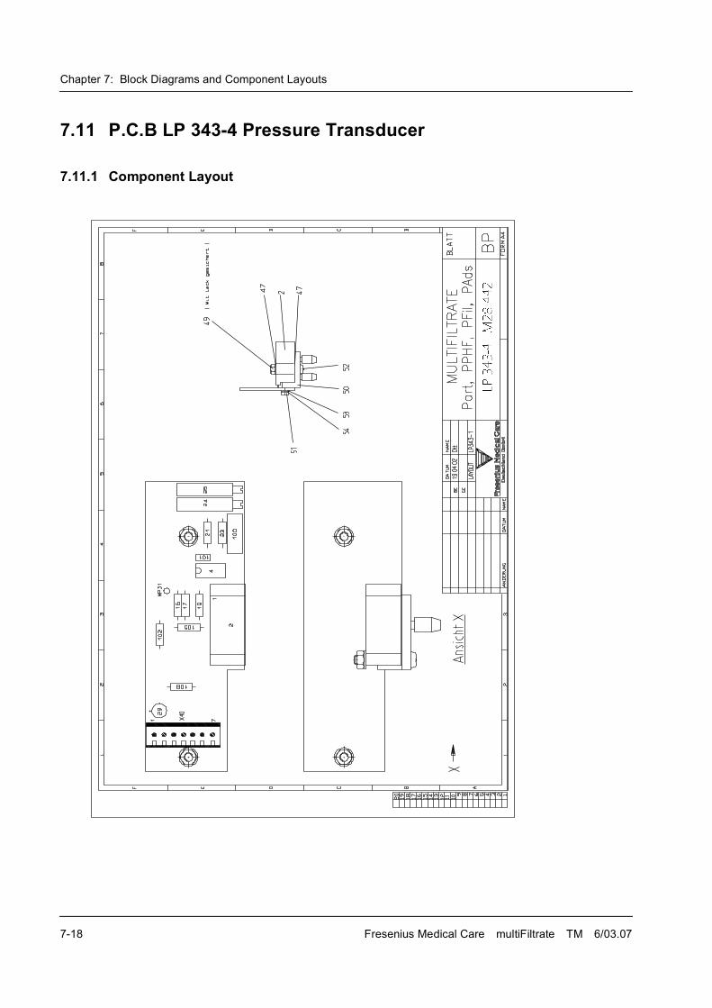
Chapter 7: Block Diagrams and Component Layouts
7-18 Fresenius Medical Care multiFiltrate TM 6/03.07
7.11 P.C.B LP 343-4 Pressure Transducer
7.11.1 Component Layout
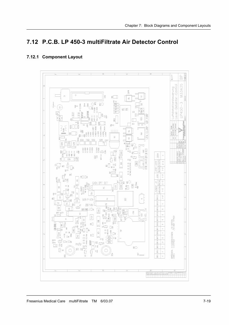
Chapter 7: Block Diagrams and Component Layouts
Fresenius Medical Care multiFiltrate TM 6/03.07 7-19
7.12 P.C.B. LP 450-3 multiFiltrate Air Detector Control
7.12.1 Component Layout
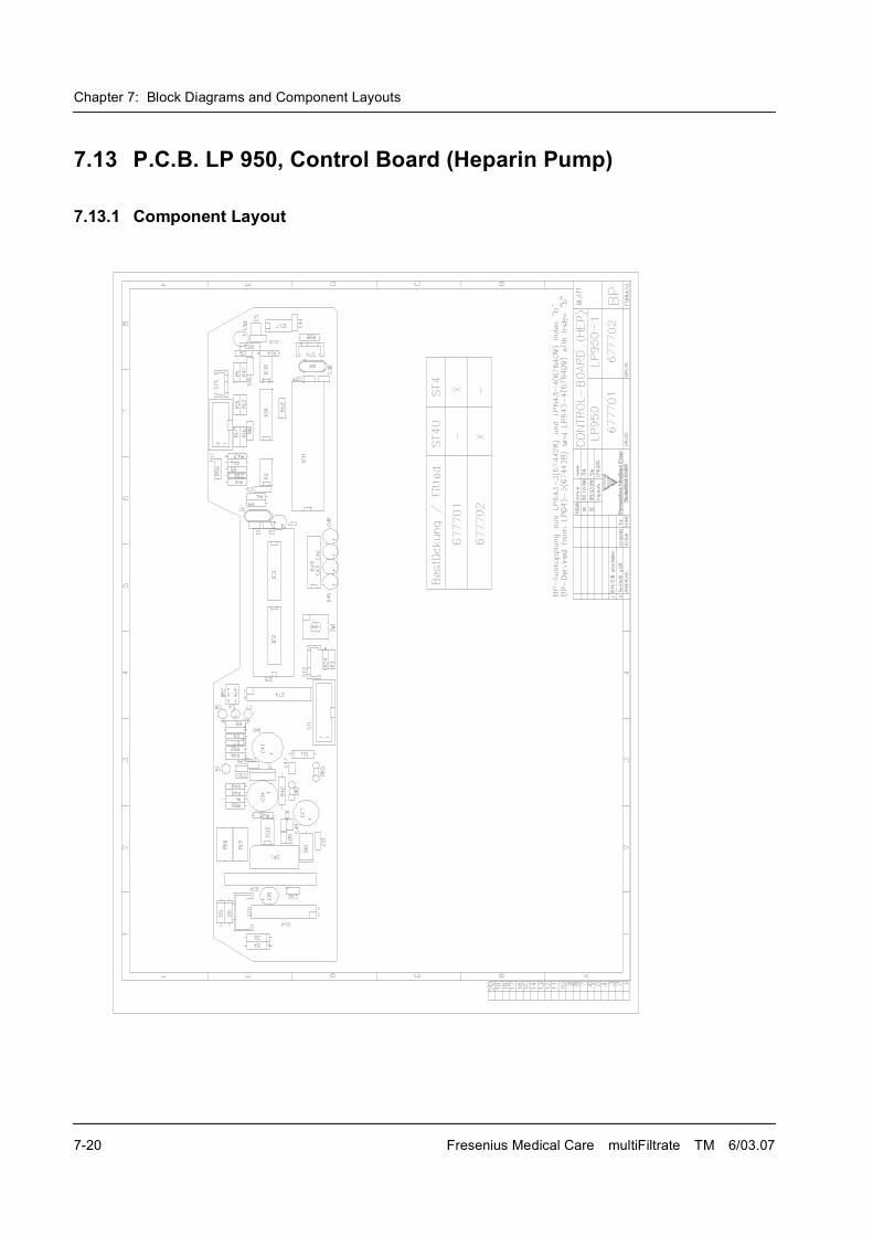
Chapter 7: Block Diagrams and Component Layouts
7-20 Fresenius Medical Care multiFiltrate TM 6/03.07
7.13 P.C.B. LP 950, Control Board (Heparin Pump)
7.13.1 Component Layout
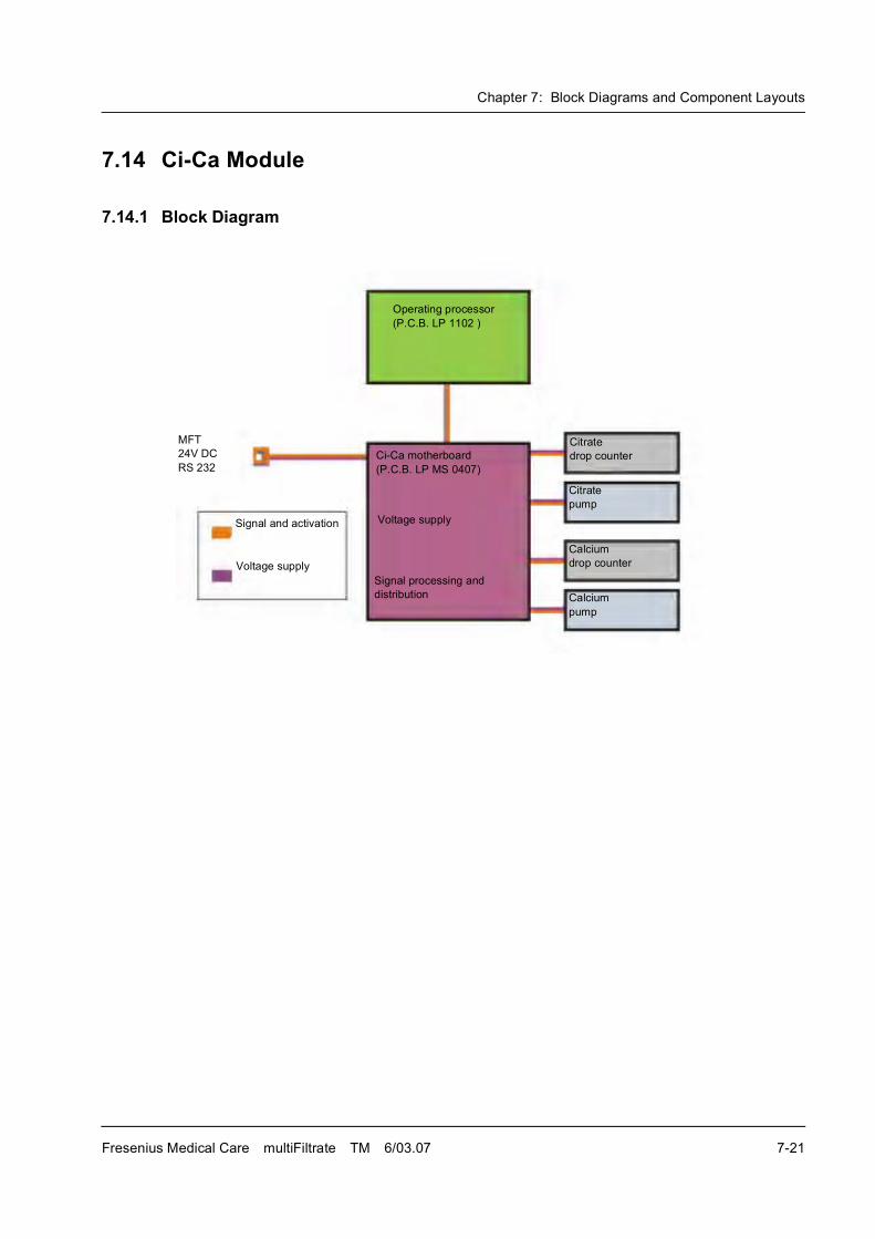
Chapter 7: Block Diagrams and Component Layouts
Fresenius Medical Care multiFiltrate TM 6/03.07 7-21
7.14 Ci-Ca Module
7.14.1 Block Diagram
Citrate
drop counter
Citrate
pump
Calcium
drop counter
Calcium
pump
Ci-Ca motherboard
(P.C.B. LP MS 0407)
Voltage supply
Signal processing and
distribution
Signal and activation
Voltage supply
MFT
24V DC
RS 232
Operating processor
(P.C.B. LP 1102 )
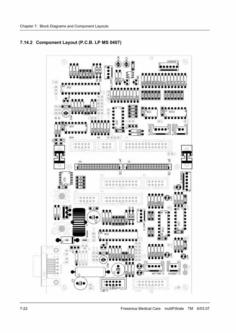
Chapter 7: Block Diagrams and Component Layouts
7-22 Fresenius Medical Care multiFiltrate TM 6/03.07
7.14.2 Component Layout (P.C.B. LP MS 0407)


![Ifm derivatives 01[1].03.07](https://img.pdfslide.us/doc/110x75/54bd573a4a7959df428b4652/ifm-derivatives-0110307.jpg)