Embed Size (px)
Citation preview
PRINCIPLE OF OPERATIONThe MLT-FD5/D electro-hydraulic proportional actuator has been
designed to shift a directional control valve spool either directly
(FL version) or by means of a servo-piston mechanically connected
to it (SP version). The internal closed
loop position control configuration
of the MLT-FD5/D makes the valve
spool achieve the desired position
with accuracy levels approaching
the performance of a servo-valve,
by continuously comparing the set-
point of a remote control device
(Potentiometer, Joystick, Machine
Management System) with the
feed-back signal generated by a
high-precision hall effect position
transducer.
FEATURESTwo Independent Proportional Valves
Control Configuration: bidirectional with MOTOR SPOOL center
position for fail-safe return to neutral in case of power loss.
Flow Rate: 0.2 to 0.5 lt/min. max. flow requirement under normal
conditions.
Work Pressure: 12 to 35 bar.
Built-in Electronics
MLT-FD5-D (digital): microprocessor-based actuator.
Choice between different types of control:
- Analog control (0 – 5V), with following auxiliary signals available:
✓ spool position feedback.
✓ 5V for external potentiometer or joystick.
- CANbus control (J1939 or CANopen protocols).
MLT-FD5-0 (on-off): 12 or 24V version.
APPLICATIONS• High performance proportional control of stackable or
monoblock directional control valves.
• Proportional control of variable displacement pumps and
motors.
• Engine governor RPM controls.
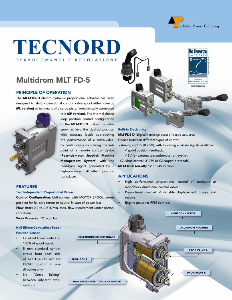
ELECTRONIC CIRCUIT BOARD
PROP. COILS
HALL EFFECT POSITION TRANSDUCER
4-PIN CONNECTOR
ALUMINUM HOUSING
PROP. VALVE A
PROP. VALVE B
Multidrom MLT FD-5
Hall Effect/Contactless Spool
Position Sensor
• Excellent linear control on
100% of spool travel.
• 8 mm standard control
stroke from each side
of NEUTRAL/13 mm for
FLOAT position in one
direction only.
• No “Cross Talking”
between adjacent work
sections.
Org
anis
mo
accr
edita
to d
a A
CC
RED
IA
UNI EN ISO 9001:2015UNI EN ISO 14001:2015
UNI EN ISO 9001:2015UNI EN ISO 14001:2015
SISTEMA DI GESTIONECERTIFICATO
Bod
y ac
cred
ited
by A
CC
RED
IA
CERTIFIEDMANAGEMENT SYSTEM
MLT-FD5 CL o s e D Lo o p pr o p o rT i o n a L aC T u aT o r
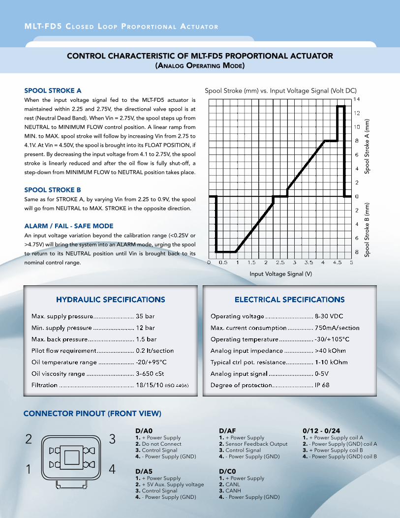
SPOOL STROKE A
When the input voltage signal fed to the MLT-FD5 actuator is
maintained within 2.25 and 2.75V, the directional valve spool is at
rest (Neutral Dead Band). When Vin = 2.75V, the spool steps up from
NEUTRAL to MINIMUM FLOW control position. A linear ramp from
MIN. to MAX. spool stroke will follow by increasing Vin from 2.75 to
4.1V. At Vin = 4.50V, the spool is brought into its FLOAT POSITION, if
present. By decreasing the input voltage from 4.1 to 2.75V, the spool
stroke is linearly reduced and after the oil flow is fully shut-off, a
step-down from MINIMUM FLOW to NEUTRAL position takes place.
SPOOL STROKE BSame as for STROKE A, by varying Vin from 2.25 to 0.9V, the spool
will go from NEUTRAL to MAX. STROKE in the opposite direction.
ALARM / FAIL - SAFE MODEAn input voltage variation beyond the calibration range (<0.25V or
>4.75V) will bring the system into an ALARM mode, urging the spool
to return to its NEUTRAL position until Vin is brought back to its
nominal control range.
Spool Stroke (mm) vs. Input Voltage Signal (Volt DC)
ConTroL CHaraCTerisTiC oF MLT-FD5 proporTionaL aCTuaTor (anaLog operaTing MoDe)
HYDRAULIC SPECIFICATIONS ELECTRICAL SPECIFICATIONS
CONNECTOR PINOUT (FRONT VIEW)
D/A01. + Power Supply2. Do not Connect3. Control Signal4. - Power Supply (GND)
D/A51. + Power Supply2. + 5V Aux. Supply voltage3. Control Signal4. - Power Supply (GND)
D/AF1. + Power Supply2. Sensor Feedback Output3. Control Signal4. - Power Supply (GND)
D/C01. + Power Supply2. CANL3. CANH4. - Power Supply (GND)
0/12 - 0/241. + Power Supply coil A2. - Power Supply (GND) coil A3. + Power Supply coil B4. - Power Supply (GND) coil B
2
1
3
4
Spoo
l Str
oke
A (m
m)
Spoo
l Str
oke
B (m
m)
Input Voltage Signal (V)
MLT-FD5 CL o s e D Lo o p pr o p o rT i o n a L aC T u aT o r
ACTUATORS SELECTION GUIDE
MLT/FD5 - X / X X
Actuator family Electronic circuit Type of control signal Auxiliary function
A= Analog VoltageC= CANbus
12=12V On/Off24=24V On/Off
D= Digital (microprocessor)0= On/Off
0= None5= 5V aux supplyF= Feedback
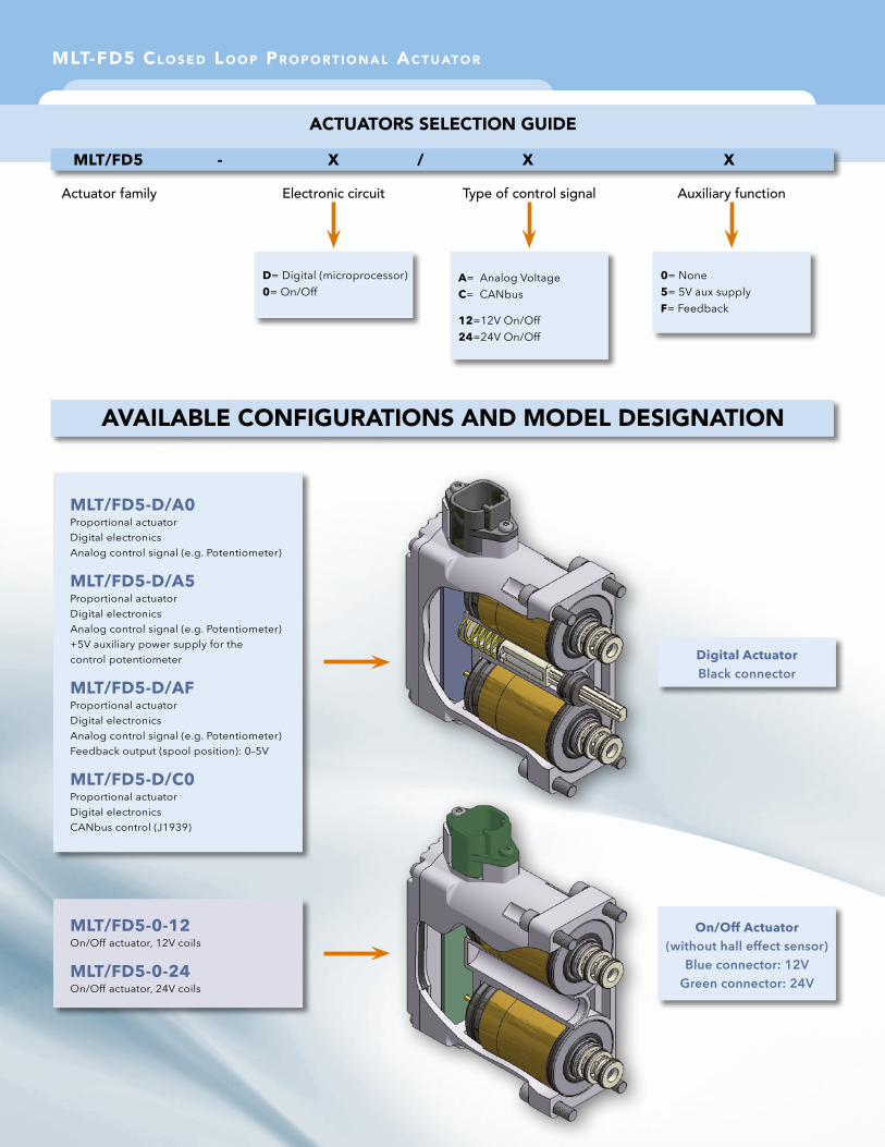
AVAILABLE CONFIGURATIONS AND MODEL DESIGNATION
MLT/FD5-D/A0Proportional actuatorDigital electronicsAnalog control signal (e.g. Potentiometer)
MLT/FD5-D/A5Proportional actuatorDigital electronicsAnalog control signal (e.g. Potentiometer)+5V auxiliary power supply for the control potentiometer
MLT/FD5-D/AFProportional actuatorDigital electronicsAnalog control signal (e.g. Potentiometer)Feedback output (spool position): 0–5V
MLT/FD5-D/C0Proportional actuatorDigital electronicsCANbus control (J1939)
MLT/FD5-0-12On/Off actuator, 12V coils
MLT/FD5-0-24On/Off actuator, 24V coils
Digital ActuatorBlack connector
On/Off Actuator(without hall effect sensor)
Blue connector: 12VGreen connector: 24V
Via Malavolti, 36 - 41122 Modena - Italy - Tel. +39 (059) 254895 - Fax +39 (059) 253512
[email protected] - www.tecnord.com
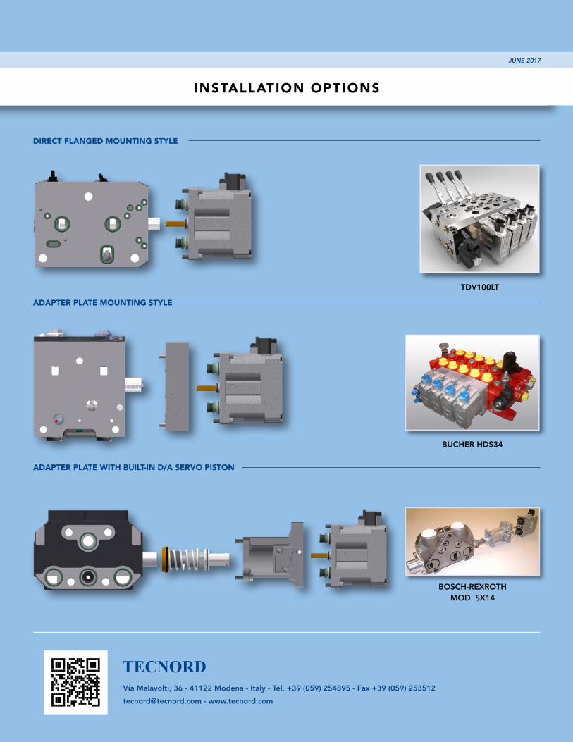
INSTALLATION OPTIONS
ADAPTER PLATE MOUNTING STYLE
BUCHER HDS34
DIRECT FLANGED MOUNTING STYLE
TDV100LT
ADAPTER PLATE WITH BUILT-IN D/A SERVO PISTON
BOSCH-REXROTH MOD. SX14
JUNE 2017