Embed Size (px)
Citation preview
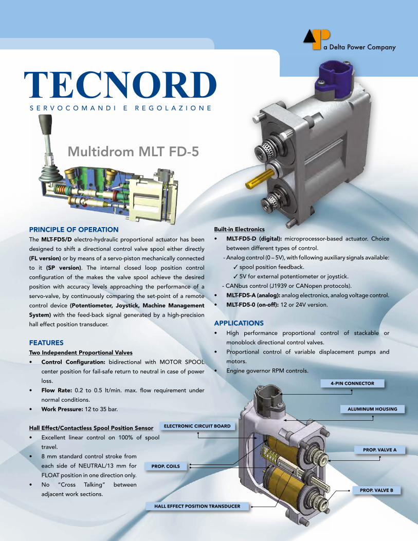
PRINCIPLE OF OPERATIONThe MLT-FD5/D electro-hydraulic proportional actuator has been
designed to shift a directional control valve spool either directly
(FL version) or by means of a servo-piston mechanically connected
to it (SP version). The internal closed loop position control
configuration of the makes the valve spool achieve the desired
position with accuracy levels approaching the performance of a
servo-valve, by continuously comparing the set-point of a remote
control device (Potentiometer, Joystick, Machine Management
System) with the feed-back signal generated by a high-precision
hall effect position transducer.
FEATURESTwo Independent Proportional Valves
• Control Configuration: bidirectional with MOTOR SPOOL
center position for fail-safe return to neutral in case of power
loss.
• Flow Rate: 0.2 to 0.5 lt/min. max. flow requirement under
normal conditions.
• Work Pressure: 12 to 35 bar.
Hall Effect/Contactless Spool Position Sensor
• Excellent linear control on 100% of spool
travel.
• 8 mm standard control stroke from
each side of NEUTRAL/13 mm for
FLOAT position in one direction only.
• No “Cross Talking” between
adjacent work sections.
Built-in Electronics
• MLT-FD5-D (digital): microprocessor-based actuator. Choice
between different types of control.
- Analog control (0 – 5V), with following auxiliary signals available:
✓ spool position feedback.
✓ 5V for external potentiometer or joystick.
- CANbus control (J1939 or CANopen protocols).
• MLT-FD5-A (analog): analog electronics, analog voltage control.
• MLT-FD5-0 (on-off): 12 or 24V version.
APPLICATIONS• High performance proportional control of stackable or
monoblock directional control valves.
• Proportional control of variable displacement pumps and
motors.
• Engine governor RPM controls.
Multidrom MLT FD-5
ELECTRONIC CIRCUIT BOARD
PROP. COILS
HALL EFFECT POSITION TRANSDUCER
4-PIN CONNECTOR
ALUMINUM HOUSING
PROP. VALVE A
PROP. VALVE B
MLT-FD5 CL o s e D Lo o p pr o p o rT i o n a L aC T u aT o r
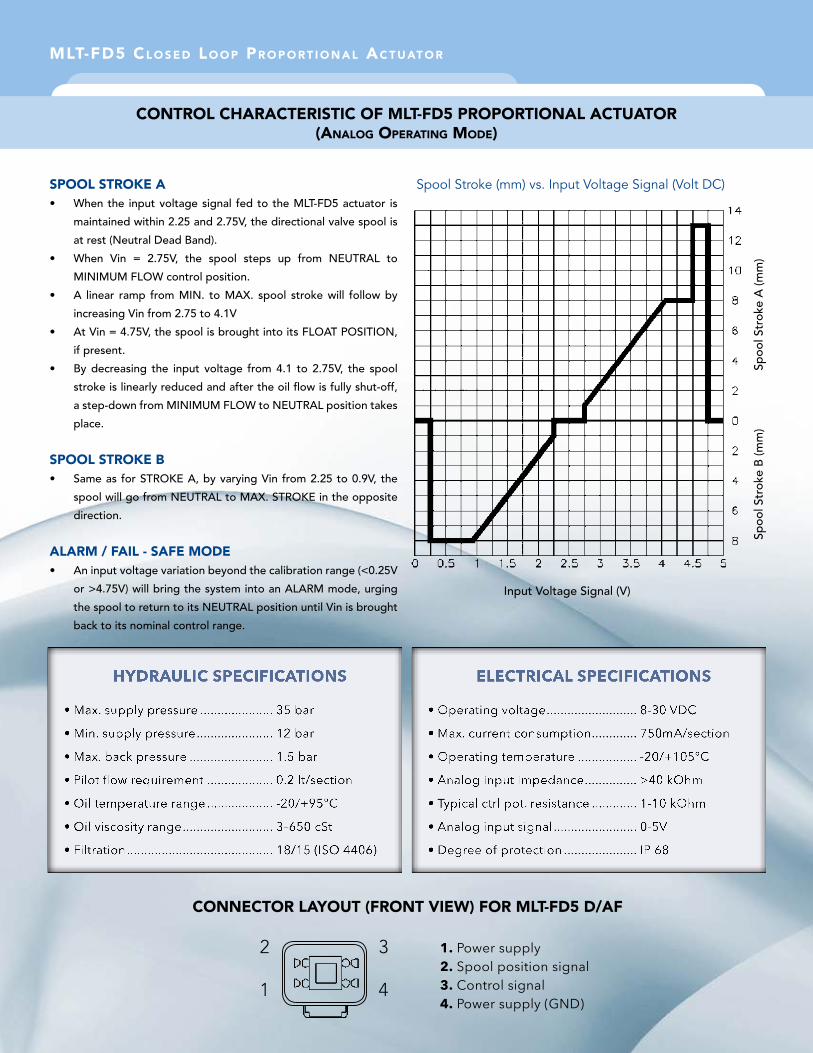
SPOOL STROKE A
• When the input voltage signal fed to the MLT-FD5 actuator is
maintained within 2.25 and 2.75V, the directional valve spool is
at rest (Neutral Dead Band).
• When Vin = 2.75V, the spool steps up from NEUTRAL to
MINIMUM FLOW control position.
• A linear ramp from MIN. to MAX. spool stroke will follow by
increasing Vin from 2.75 to 4.1V
• At Vin = 4.75V, the spool is brought into its FLOAT POSITION,
if present.
• By decreasing the input voltage from 4.1 to 2.75V, the spool
stroke is linearly reduced and after the oil flow is fully shut-off,
a step-down from MINIMUM FLOW to NEUTRAL position takes
place.
SPOOL STROKE B• Same as for STROKE A, by varying Vin from 2.25 to 0.9V, the
spool will go from NEUTRAL to MAX. STROKE in the opposite
direction.
ALARM / FAIL - SAFE MODE• An input voltage variation beyond the calibration range (<0.25V
or >4.75V) will bring the system into an ALARM mode, urging
the spool to return to its NEUTRAL position until Vin is brought
back to its nominal control range.
Spool Stroke (mm) vs. Input Voltage Signal (Volt DC)
ConTroL CHaraCTerisTiC oF MLT-FD5 proporTionaL aCTuaTor (anaLog operaTing MoDe)
HYDRAULIC SPECIFICATIONS ELECTRICAL SPECIFICATIONS
CONNECTOR LAYOUT (FRONT VIEW) FOR MLT-FD5 D/aF
1. Power supply2. Spool position signal3. Control signal4. Power supply (GND)
2
1
3
4
Spoo
l Str
oke
A (m
m)
Spoo
l Str
oke
B (m
m)
Input Voltage Signal (V)
MLT-FD5 CL o s e D Lo o p pr o p o rT i o n a L aC T u aT o r
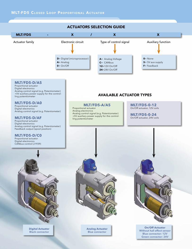
ACTUATORS SELECTION GUIDE
CONNECTOR LAYOUT (FRONT VIEW) FOR MLT-FD5 D/aF
MLT/FD5 - X / X X
Actuator family Electronic circuit Type of control signal Auxiliary function
A= Analog VoltageC= CANbus12=12V On/Off24=24V On/Off
D= Digital (microprocessor)A= Analog0= On/Off
0= None5= 5V aux supplyF= Feedback
AVAILABLE ACTUATOR TYPES
MLT/FD5-D/A5Proportional actuatorDigital electronicsAnalog control signal (e.g. Potentiometer)+5V auxiliary power supply for the control-ling potentiometer
MLT/FD5-D/A0Proportional actuatorDigital electronicsAnalog control signal (e.g. Potentiometer)
MLT/FD5-D/AFProportional actuatorDigital electronicsAnalog control signal (e.g. Potentiometer)Feedback output (spool position)
MLT/FD5-D/C0Proportional actuatorDigital electronicsCANbus control (J1939)
MLT/FD5-A/A5Proportional actuatorAnalog electronicsAnalog control signal (e.g. Potentiometer)+5V auxiliary power supply for the control-ling potentiometer
MLT/FD5-0-12On/Off actuator, 12V coils
MLT/FD5-0-24On/Off actuator, 24V coils
Digital ActuatorBlack connector
Analog ActuatorBlue connector
On/Off ActuatorWithout hall effect sensor
Blue connector: 12VGreen connector: 24V
Via Malavolti, 36 - 41122 Modena - Italy - Tel. +39-059-254895 - Fax +39-059-253512
[email protected] - www.tecnord.com
PRINTED ON JANUARY 2015
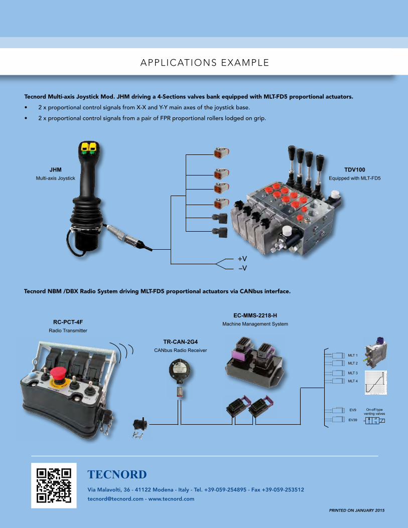
APPLICATIONS EXAMPLE
Tecnord Multi-axis Joystick Mod. JHM driving a 4-Sections valves bank equipped with MLT-FD5 proportional actuators.
• 2 x proportional control signals from X-X and Y-Y main axes of the joystick base.
• 2 x proportional control signals from a pair of FPR proportional rollers lodged on grip.
Tecnord NBM /DBX Radio System driving MLT-FD5 proportional actuators via CANbus interface.
EC-MMS-2218-H Machine Management System
TR-CAN-2G4CANbus Radio Receiver
RC-PCT-4FRadio Transmitter
+V–V
JHMMulti-axis Joystick
TDV100Equipped with MLT-FD5
RS232PC
ADAPTER
DB9FCONNECTOR
DEAD MANOn-off bidirectional valve
On-off bidirectional valve
On-off bidirectional valve
On-off bidirectional valve
On-off bidirectional valve
Proportional flow regulator
On-off typeventing valve
EV1A
EV1B
EV2A
EV2B
EV3A
EV3B
EV4A
EV4B
EV5A
EV5B
EVP
EV9
MLT 1
MLT 2
MLT 3
MLT 4
EV9
EV39
RS232PC
ADAPTER
DB9FCONNECTOR
DEAD MANOn-off bidirectional valve
On-off bidirectional valve
On-off bidirectional valve
On-off bidirectional valve
On-off bidirectional valve
Proportional flow regulator
On-off typeventing valve
EV1A
EV1B
EV2A
EV2B
EV3A
EV3B
EV4A
EV4B
EV5A
EV5B
EVP
EV9 On-off typeventing valves