Embed Size (px)
Citation preview
8. H.Y. Yang and N.G. Alexopoulos, Gain enhancement methods forprinted circuit antennas through multiple substrates, IEEE Trans An-tennas Propag AP-35 (1987), 860–863.
9. J. Bahl, P. Bhartia, and S.S. Stuchly, Design of microstrip antennascovered with a dielectric layer, IEEE Trans Antennas Propag AP-30(1982), 314–318.
10. Q. Lee, K.F. Lee, and J. Bobinchak, Characteristics of a two-layerelectromagnetically coupled rectangular patch antenna, Electron Lett23 (1987), 1070–1072.
11. R.Q. Lee and K.F. Lee, Effects of parasitic patch sizes on multi-layerelectromagnetically coupled patch antenna, Proc IEEE Int Symp An-tennas Propag Soc 2 (1989), 624–627.
12. C. You, M.M. Tentzeris, and W. Hwang, Multilayer effects on mi-crostrip antennas for their integration with mechanical structures,IEEE Trans Antennas Propag AP-55 (2007), 1051–1058.
13. U. Sangawa, T. Urabe, Y. Kudoh, A. Omote, and K. Takahashi, Astudy on a 60 GHz low profile dielectric lens antenna using high-permittivity ceramics—toward a low profile antenna, IEICE, Tokyo,Japan, Tech Rep MW2002–116, November 2002.
14. H. Legay and L. Shafai, A new stacked microstrip antenna withlarge bandwidth and high gain, Proc IEEE AP-S Int Symp (1993),948 –951.
15. S.D. Targonski, R.B. Waterhouse, and D.M. Pozar, Design of wide-band aperture-stacked patch microstrip antennas, IEEE Trans Anten-nas Propag 46 (1998), 1245–1251.
16. R.B. Waterhouse, Stacked patches using high and low dielectric con-stant material combinations, IEEE Trans Antennas Propag 47 (1999),1767–1771.
17. R. Li, G. Dejean, M. Maeng, K. Lim, S. Pinel, M.M. Tentzeris, and J.Laskar, Design of compact stacked-patch antennas in LTCC multilayerpackaging modules for wireless applications, IEEE Trans Adv Packag27 (2004), 581–589.
18. E. Nishiyama, M. Aikawa, and S. Egashira, Three-element stackedmicrostrip antenna with wide-band and high-gain performances, IntIEEE AP-S Symp Dig 2 (2003), 900–903.
19. R.Q. Lee and K.F. Lee, Experimental study of two layer electromag-netically coupled rectangular patch antenna, IEEE Trans AntennasPropag 38 (1990), 1298–1302.
20. S. Egashira and E. Nishiyama, Stacked microstrip antenna with widebandwidth and high gain, IEEE Trans Antennas Propag 44 (1996),1533–1534.
21. N. Hasebe, R. Hiramatsu, and N. Masuda, A disk coupled resonantantenna excited by a circular patch, Int IEEE AP-S Symp Dig (1985),122–125.
22. T. Seki, K. Nishikawa, and K. Cho, Multi-layer parasitic microstriparray antenna on LTCC substrate for millimeter- wave system-on-package, In: Proceedings of 33rd European Microwave Conference,Munich, Germany, October 2003, pp. 1393–1396.
23. T. Seki, N. Honma, K. Nishikawa, and K. Tsunekawa, High efficiencymultilayer parasitic microstrip array antenna on Teflon substrate, inProceedings of 34th European Microwave Conference, Amsterdam,Holland, October 2004, pp. 829–832.
24. T. Seki, N. Honma, K. Nishikawa, and K. Tsunekawa, Millimeter-wave high-efficiency multilayer parasitic microstrip antenna array onteflon substrate, IEEE Trans Microwave Theory Tech 53 (2005),2101–2106.
25. D.M. Pozar, S.D. Targonski, and H. Syrigos, Design of millimeterwave microstrip reflectarrays, IEEE Trans Antennas Propag AP-45(1997), 287–295.
26. R.D. Javor, X.D. Wu, and K. Chang, Design and performance of amicrostrip reflectarray antenna, IEEE Trans Antennas Propag AP-43(1995), 932–939.
27. J. Huang and R.J. Pogorzelski, A Ka band microstrip reflectarray withelements having variable rotation angles, IEEE Trans Antennas PropagAP46 (1998), 650–656.
28. W. Choi, Y.H. Cho, C. Pyo, and J. Choi, High gain microstrip patcharray antenna using a superstrate layer, ETRI J 25 (2003).
29. P.N. Chine and G. Kumar, Three dimensional, efficient, directivemicrostrip antenna arrays, IEEE International Symposium on Antennaand Propagation, Washington DC, July 2005.
30. R.K. Gupta and G. Kumar, High gain multilayered antenna for wire-less communication, Microwave Opt Technol Lett 50 (2008), 1923–1929.
31. IE3D release 12.0, Zeland software Inc., Fremont, CA, USA, 2006.
© 2009 Wiley Periodicals, Inc.
MULTIBAND INTERNAL MONOPOLEANTENNA FOR MOBILE PHONES
Rashid Ahmad Bhatti, Yun-Taek Im, Nguyen Ngoc Anh, andSeong-Ook ParkMA Lab, Information and Communications University (ICU), Daejeon,Korea; Corresponding author: [email protected]
Received 6 July 2008
ABSTRACT: A low-profile internal monopole antenna has been pro-posed for multistandard mobile phones. The proposed antenna operatesat GSM (880–960 MHz), DCS (1710–1880 MHz), PCS (1850–1990MHz), UMTS (1920–2170 MHz), WiBro (2300–2390 MHz), Bluetooth(2.42–2.48 GHz), S-DMB (2.630–2.655 GHz), and WLAN (5.1–5.37,5.75–5.9 GHz) frequency bands. Multiple resonators have been con-nected in parallel in a compact configuration to realize a miniaturizedinternal antenna for modern multistandard handsets. The proposedmonopole antenna has been designed within a volume of 0.43 cm3 (20mm � 14 mm � 1.5 mm) that makes it suitable for ultra-thin mobileterminals. Two prototype antennas have been fabricated and character-ized for return losses and radiation performances which are quite rea-sonable at all the targeted frequency bands. © 2009 Wiley Periodicals,Inc. Microwave Opt Technol Lett 51: 739–742, 2009; Published onlinein Wiley InterScience (www.interscience.wiley.com). DOI 10.1002/mop.24178
Key words: monopole; small antenna; multiband; handset
1. INTRODUCTION
Modern handsets are required to support various wireless stan-dards to provide location independent communication services likevoice, data, video, internet, and multimedia content while main-taining their weight, volume, and compactness [1]. Space availablefor antenna in the handset is getting reduced because of theimplementation of additional circuitry to support multiple globalstandards and services. Another emerging trend in the wirelesscommunication industry is to design slim handsets that need re-duced height antennas. New miniaturized antenna designs aretherefore needed to meet the emerging needs of the modern slimhandsets. Commonly used antennas for handset applications in-clude monopoles and planar inverted-F antennas (PIFA). PIFA canrespond to both vertically and horizontally polarized field compo-nents which is highly desirable in mobile communication applica-tions [2]. Many interesting multiband PIFA elements have beenreported in the literature [3–6]. Volume occupied by each of theseantennas ranges from 3.5 cm3 to 5 cm3 which is not attractive formodern slim mobile phones. Internal monopole antennas can alsobe realized in planar or printed form with reasonable electricalperformances. Various techniques such as meandering and reactiveloading are generally used to design compact monopole antennas.Multiple resonators can be arranged in an appropriate configura-tion to realize multiband internal monopole antennas. Widebandmonopole planar and printed antennas have been reported in the
DOI 10.1002/mop MICROWAVE AND OPTICAL TECHNOLOGY LETTERS / Vol. 51, No. 3, March 2009 739
literature [7–10]. Significant footprint of these antennas is a lim-itation for space-constrained multistandard handsets.
In this article, design of a multiresonator-based folded mono-pole antenna has been proposed for multifunctional mobile phones.The proposed monopole antenna can support the following fre-quency bands: GSM (Global System for Mobile Communications,880–960 MHz), DCS (Digital Communication System, 1710–1880 MHz), PCS (Personal Communication Services, 1850–1990MHz), UMTS (Universal Mobile Telecommunications System,
1920–2170 MHz), WiBro (2300–2390 MHz), Bluetooth (2.4–2.48 GHz), S-DMB (Satellite-Digital Multimedia Broadcasting,2.630–2.655 GHz), and WLAN (Wireless Local Area Network,5.1–5.9 GHz).
2. ANTENNA DESIGN METHODOLOGY
Figure 1 shows structural details of the proposed antenna andFigure 2 shows the simulated results. The antenna has been de-signed within a rectangular area of 20 mm � 14 mm with a heightof 1.5 mm (0.42 cm3) and located at the left top of FR-4 substrate(�r � 4.5) measuring 107 mm � 48 mm. A semiridged coaxial
Figure 1 Structural configuration of the proposed antenna (a) three-dimensional perspective (b) dimensional details of the lower and upperparts of the antenna
Frequency (GHz)
1 2 3 4 5 6 7
S11
(dB
)
-20
-15
-10
-5
0
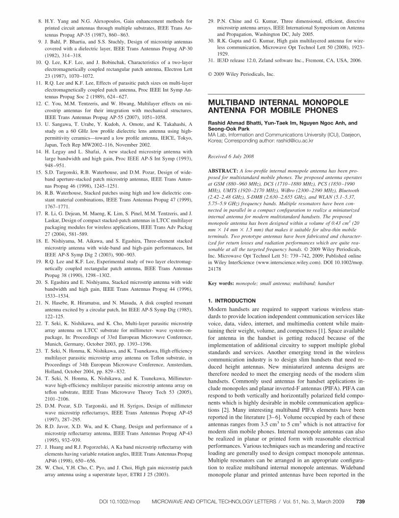
Folded Monopole OnlyMonopole + 1.8 GHz ResonatorMonopole + 1.8 GHz Resonator + 5.2 GHz Patch
Figure 2 Simulated return losses showing behavior of various resonatorsin the antenna structure
Phase Reversal
a
(a)
(b)
Phase
reversa
l
b
(c)
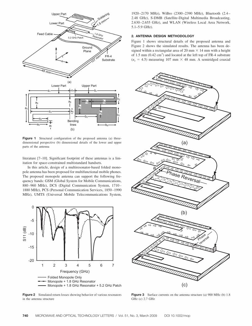
Figure 3 Surface currents on the antenna structure (a) 900 MHz (b) 1.8GHz (c) 2.7 GHz
740 MICROWAVE AND OPTICAL TECHNOLOGY LETTERS / Vol. 51, No. 3, March 2009 DOI 10.1002/mop
cable is used to feed the monopole antenna. Outer shield of thecoaxial cable has been soldered to the PCB ground plane. Theantenna design concept is based on parallel-connected multipleresonators operating at different frequencies. Primarily, the an-tenna consists of three quarter-wave resonators operating at 900MHz, 1.8 GHz, and 5.2 GHz, respectively. The three resonatorsare connected in parallel and arranged in a compact configurationin order to get a low profile antenna structure. The longest reso-nator has been folded while maintaining 1.5 mm height between itsupper and lower parts. It acts as a quarter-wave resonator at around900 MHz. Surface current distribution on the longest resonator at900 MHz is shown in Figure 3(a). At 900 MHz, there are negli-gible currents on the 1.8 GHz and 5.2 GHz resonators. To getwideband characteristics across 2 GHz, a quarter wave resonator of1.8 GHz is connected in parallel with the main antenna element.Length of 1.8 GHz resonator is 19 mm which is close to quarter-wavelength (19.4 mm) at 1.8 GHz on FR-4 substrate. Main an-tenna element operates as a 3�/4 resonator. Figures 3(b) and 3(c)show 3�/4 behavior of the longest resonator through surface cur-rent distributions and phase reversal points a and b, respectively.Addition of 1.8 GHz resonator in the antenna significantly im-proves the bandwidth across 2 GHz frequency covering most ofthe cellular bands. To cover WLAN frequency bands, a quarterwave resonator at 5.2 GHz is attached in parallel with the otherresonators at an appropriate location. It does not adversely affect
Frequency (GHz)
1 2 3 4 5 6 7
S11
(dB
)
-20
-15
-10
-5
0
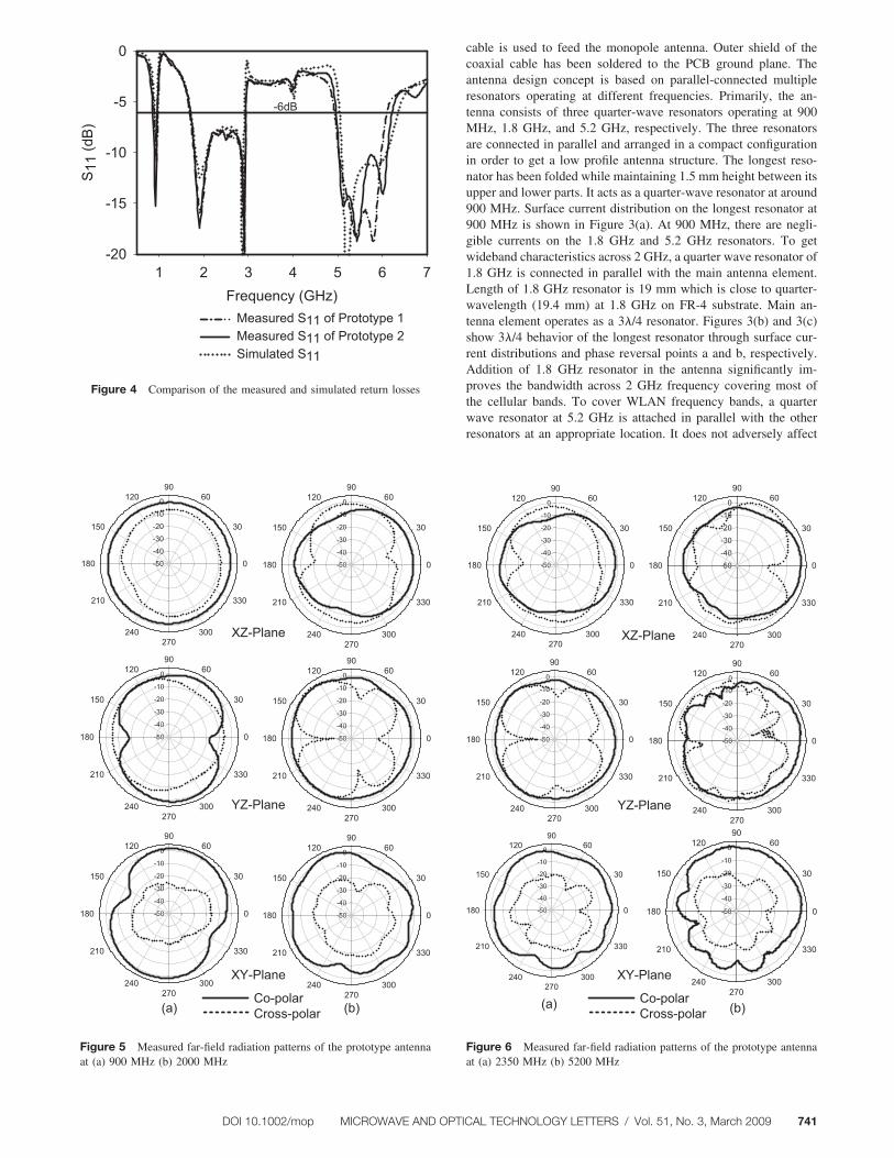
Measured S11 of Prototype 1Measured S11 of Prototype 2Simulated S11
-6dB
Figure 4 Comparison of the measured and simulated return losses
-50
-40
-30
-20
-10
0
0
30
6090
120
150
180
210
240270
300
330
-50
-40
-30
-20
-10
0
0
30
6090
120
150
180
210
240270
300
330
-50
-40
-30
-20
-10
0
0
30
6090
120
150
180
210
240270
300
330
-50
-40
-30
-20
-10
0
0
30
6090
120
150
180
210
240270
300
330
-50
-40
-30
-20
-10
0
0
30
6090
120
150
180
210
240270
300
330
-50
-40
-30
-20
-10
0
0
30
6090
120
150
180
210
240270
300
330
XZ-Plane
YZ-Plane
XY-Plane
)b()a(Co-polarCross-polar
Figure 5 Measured far-field radiation patterns of the prototype antennaat (a) 900 MHz (b) 2000 MHz
(a) (b)
-50
-40
-30
-20
-10
0
0
30
6090
120
150
180
210
240270
300
330
-50
-40
-30
-20
-10
0
0
30
6090
120
150
180
210
240270
300
330
XY-Plane
Co-polarCross-polar
-50
-40
-30
-20
-10
0
0
30
6090
120
150
180
210
240270
300
330
-50
-40
-30
-20
-10
0
0
30
6090
120
150
180
210
240270
300
330
YZ-Plane
-50
-40
-30
-20
-10
0
0
30
6090
120
150
180
210
240270
300
330
-50
-40
-30
-20
-10
0
0
30
6090
120
150
180
210
240270
300
330
XZ-Plane
Figure 6 Measured far-field radiation patterns of the prototype antennaat (a) 2350 MHz (b) 5200 MHz
DOI 10.1002/mop MICROWAVE AND OPTICAL TECHNOLOGY LETTERS / Vol. 51, No. 3, March 2009 741
the rest of the antenna performances and the antenna’s footprintremains the same. Behavior of the three resonators in the antennahas been explained in Figure 2. CST Microwave Studio is used forfull wave analysis and optimization of the monopole antennastructure. Perfect electric conductor (PEC) is assumed in the sim-ulation setup and the antenna structure is excited with an idealdiscrete port. Physical dimensions (in mm) of the proposed an-tenna are as follows: a1 � 20, a2 � 14, a3 � 19, a4 � 7.4, a5 �9.5, a6 � 5.5, a7 � 1, a8 � 1.5, a9 � 3.0, b1 � 20, b2 � 5, b3 �3.5, b4 � 7.5, b5 � 11, b6 � 9, b7 � 7.5, b8 � 1.5, b9 � 10, h �1.5.
3. TEST RESULTS
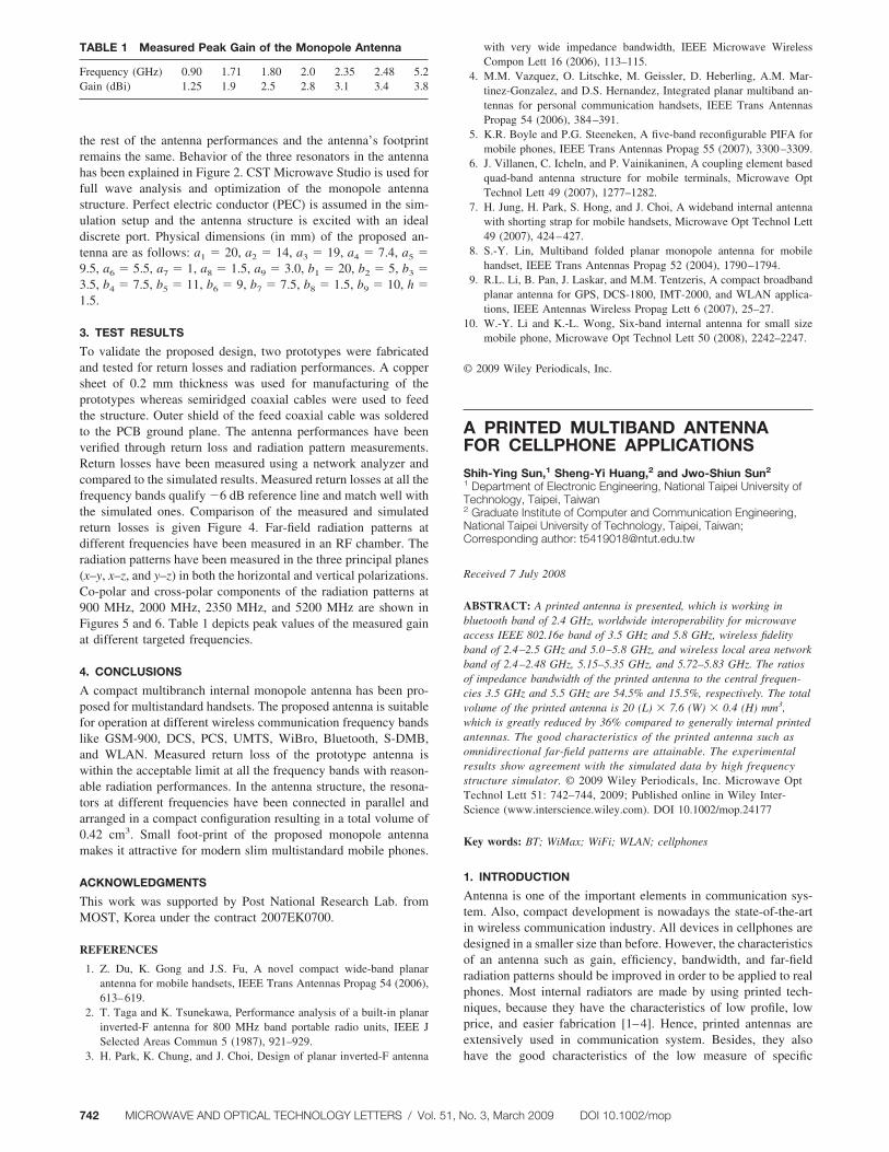
To validate the proposed design, two prototypes were fabricatedand tested for return losses and radiation performances. A coppersheet of 0.2 mm thickness was used for manufacturing of theprototypes whereas semiridged coaxial cables were used to feedthe structure. Outer shield of the feed coaxial cable was solderedto the PCB ground plane. The antenna performances have beenverified through return loss and radiation pattern measurements.Return losses have been measured using a network analyzer andcompared to the simulated results. Measured return losses at all thefrequency bands qualify �6 dB reference line and match well withthe simulated ones. Comparison of the measured and simulatedreturn losses is given Figure 4. Far-field radiation patterns atdifferent frequencies have been measured in an RF chamber. Theradiation patterns have been measured in the three principal planes(x–y, x–z, and y–z) in both the horizontal and vertical polarizations.Co-polar and cross-polar components of the radiation patterns at900 MHz, 2000 MHz, 2350 MHz, and 5200 MHz are shown inFigures 5 and 6. Table 1 depicts peak values of the measured gainat different targeted frequencies.
4. CONCLUSIONS
A compact multibranch internal monopole antenna has been pro-posed for multistandard handsets. The proposed antenna is suitablefor operation at different wireless communication frequency bandslike GSM-900, DCS, PCS, UMTS, WiBro, Bluetooth, S-DMB,and WLAN. Measured return loss of the prototype antenna iswithin the acceptable limit at all the frequency bands with reason-able radiation performances. In the antenna structure, the resona-tors at different frequencies have been connected in parallel andarranged in a compact configuration resulting in a total volume of0.42 cm3. Small foot-print of the proposed monopole antennamakes it attractive for modern slim multistandard mobile phones.
ACKNOWLEDGMENTS
This work was supported by Post National Research Lab. fromMOST, Korea under the contract 2007EK0700.
REFERENCES
1. Z. Du, K. Gong and J.S. Fu, A novel compact wide-band planarantenna for mobile handsets, IEEE Trans Antennas Propag 54 (2006),613–619.
2. T. Taga and K. Tsunekawa, Performance analysis of a built-in planarinverted-F antenna for 800 MHz band portable radio units, IEEE JSelected Areas Commun 5 (1987), 921–929.
3. H. Park, K. Chung, and J. Choi, Design of planar inverted-F antenna
with very wide impedance bandwidth, IEEE Microwave WirelessCompon Lett 16 (2006), 113–115.
4. M.M. Vazquez, O. Litschke, M. Geissler, D. Heberling, A.M. Mar-tinez-Gonzalez, and D.S. Hernandez, Integrated planar multiband an-tennas for personal communication handsets, IEEE Trans AntennasPropag 54 (2006), 384–391.
5. K.R. Boyle and P.G. Steeneken, A five-band reconfigurable PIFA formobile phones, IEEE Trans Antennas Propag 55 (2007), 3300–3309.
6. J. Villanen, C. Icheln, and P. Vainikaninen, A coupling element basedquad-band antenna structure for mobile terminals, Microwave OptTechnol Lett 49 (2007), 1277–1282.
7. H. Jung, H. Park, S. Hong, and J. Choi, A wideband internal antennawith shorting strap for mobile handsets, Microwave Opt Technol Lett49 (2007), 424–427.
8. S.-Y. Lin, Multiband folded planar monopole antenna for mobilehandset, IEEE Trans Antennas Propag 52 (2004), 1790–1794.
9. R.L. Li, B. Pan, J. Laskar, and M.M. Tentzeris, A compact broadbandplanar antenna for GPS, DCS-1800, IMT-2000, and WLAN applica-tions, IEEE Antennas Wireless Propag Lett 6 (2007), 25–27.
10. W.-Y. Li and K.-L. Wong, Six-band internal antenna for small sizemobile phone, Microwave Opt Technol Lett 50 (2008), 2242–2247.
© 2009 Wiley Periodicals, Inc.
A PRINTED MULTIBAND ANTENNAFOR CELLPHONE APPLICATIONS
Shih-Ying Sun,1 Sheng-Yi Huang,2 and Jwo-Shiun Sun2
1 Department of Electronic Engineering, National Taipei University ofTechnology, Taipei, Taiwan2 Graduate Institute of Computer and Communication Engineering,National Taipei University of Technology, Taipei, Taiwan;Corresponding author: [email protected]
Received 7 July 2008
ABSTRACT: A printed antenna is presented, which is working inbluetooth band of 2.4 GHz, worldwide interoperability for microwaveaccess IEEE 802.16e band of 3.5 GHz and 5.8 GHz, wireless fidelityband of 2.4–2.5 GHz and 5.0–5.8 GHz, and wireless local area networkband of 2.4–2.48 GHz, 5.15–5.35 GHz, and 5.72–5.83 GHz. The ratiosof impedance bandwidth of the printed antenna to the central frequen-cies 3.5 GHz and 5.5 GHz are 54.5% and 15.5%, respectively. The totalvolume of the printed antenna is 20 (L) � 7.6 (W) � 0.4 (H) mm3,which is greatly reduced by 36% compared to generally internal printedantennas. The good characteristics of the printed antenna such asomnidirectional far-field patterns are attainable. The experimentalresults show agreement with the simulated data by high frequencystructure simulator. © 2009 Wiley Periodicals, Inc. Microwave OptTechnol Lett 51: 742–744, 2009; Published online in Wiley Inter-Science (www.interscience.wiley.com). DOI 10.1002/mop.24177
Key words: BT; WiMax; WiFi; WLAN; cellphones
1. INTRODUCTION
Antenna is one of the important elements in communication sys-tem. Also, compact development is nowadays the state-of-the-artin wireless communication industry. All devices in cellphones aredesigned in a smaller size than before. However, the characteristicsof an antenna such as gain, efficiency, bandwidth, and far-fieldradiation patterns should be improved in order to be applied to realphones. Most internal radiators are made by using printed tech-niques, because they have the characteristics of low profile, lowprice, and easier fabrication [1–4]. Hence, printed antennas areextensively used in communication system. Besides, they alsohave the good characteristics of the low measure of specific
TABLE 1 Measured Peak Gain of the Monopole Antenna
Frequency (GHz) 0.90 1.71 1.80 2.0 2.35 2.48 5.2Gain (dBi) 1.25 1.9 2.5 2.8 3.1 3.4 3.8
742 MICROWAVE AND OPTICAL TECHNOLOGY LETTERS / Vol. 51, No. 3, March 2009 DOI 10.1002/mop


![Multiband Monopole Antenna with Sector-Nested Fractalfractal antennas in recent years include Sierpinski fractal antenna[8], Koch fractal antenna [9] and Minkowski antenna [10] . In](https://img.pdfslide.us/doc/110x75/5e76c468024e970eb01c097c/multiband-monopole-antenna-with-sector-nested-fractal-fractal-antennas-in-recent.jpg)