Embed Size (px)
Citation preview
ACC
MULTI-SERVICE TACTICS, TECHNIQUES, AND PROCEDURES FOR
AIR CONTROL COMMUNICATION
ATP 3-52.4 MCRP 3-20F.10
NTTP 6-02.9 AFTTP 3-2.8
FEBRUARY 2020
DISTRIBUTION STATEMENT A. Approved for public release; distribution is unlimited.
FOREWORD
This multi-Service tactics, techniques, and procedures (MTTP) publication is a product of the Air Land Sea Application (ALSA) Center in accordance with the memorandum of agreement between the Headquarters of the Army, Marine Corps, Navy, and Air Force doctrine commanders directing ALSA to develop MTTP publications to meet the immediate needs of the warfighter.
This MTTP publication has been prepared by ALSA under our direction for implementation by our respective commands and for use by other commands as appropriate.
DOUGLAS C. CRISSMAN W. F. MULLEN III Major General, US Army Major General, US Marine Corps Director Commanding General Mission Command Center of Excellence Training and Education Command
J. F. MEIER BRAD M. SULLIVAN Rear Admiral, US Navy Major General, US Air Force Commander Commander Navy Warfare Development Command Curtis E. Lemay Center for Doctrine
Development and Education
This publication is available through the following websites: ALSA (http://www.alsa.mil);
US Army (https://armypubs.army.mil); US Marine Corps
(https://homeport.usmc.mil/sites/mcdoctrine/SitePages/Home.aspx); US Navy at Navy Doctrine Library (https://doctrine.navy.mil);
US Air Force at US Air Force Center for Doctrine Development and Education (http://www.doctrine.af.mil/); and Joint Electronic Library Plus
(https://jdeis.js.mil/jdeis/index.jsp?pindex=0).
14 FEB 2020 ATP 3-52.4/MCRP 3-20F.10/NTTP 6-02.9/AFTTP 3-2.8 i
PREFACE
1. Purpose
This multi-Service tactics, techniques, and procedures (MTTP) publication establishes communications tactics, techniques, and procedures (TTP) for tactical command and control (TAC C2) to manage air operations and to control airspace and aircraft. It also establishes TTP for force packaging and direct air support coordination, air-to-air (A/A) communication, A/A intercept, threat A/A warning, threat surface-to-air warning, and air-to-surface communication.
2. Scope
This publication provides MTTP for the control and coordination of air operations in TAC C2 managed areas of responsibility (AORs).
3. Applicability
This MTTP publication applies to all TAC C2 airspace control elements and warfighters that conduct air operations in AORs managed by the joint force commander (JFC) and overseen by the airspace control authority (ACA) IAW the JFC signed airspace control plan (ACP) and airspace control order (ACO). Operational planners and exercise planners can use this publication to inform the airspace control plan, the airspace control order, the special instructions, the area air defense plan, and rules of engagement.
This publication addresses an avenue for the Services to tap into the intelligence, surveillance, and reconnaissance (ISR) constellation. It provides TTP to leverage current intelligence from platforms like RQ-4H; RC-135; E-8, Joint Surveillance Target Attack Radar System; U-2; unmanned aircraft systems (UASs); space; and cyberspace by contacting the TAC C2. The TAC C2 may be manned by the United States (US) Air Force, Navy, or Marine Corps. TAC C2 would provide the current, consolidated battlespace picture.
For example, a ground force commander ordered an Apache to conduct armed reconnaissance in US Army-controlled airspace. The primary targets are enemy air defense and artillery batteries. Unit intelligence briefed the known threat and target locations before departing for a mission, but the Apache has no organic ISR for updates to those locations. During the mission, the Apache would contact TAC C2 for ISR personnel’s updated intelligence on threat and target locations. This information would enhance situational awareness and mission effectiveness.
After attacking multiple targets, the aircrew were out of ordnance but there targets remained. The aircrew would leverage the TAC C2, again, for support. Passing grid locations to TAC C2 enhanced the battlespace picture and enabled re-tasking other assets to strike the targets and support the ground force commander’s objective.
4. Implementation Plan
Participating Service command offices of primary responsibility will review this publication; validate the information; and, where appropriate, use as a reference and incorporate it in Service manuals, regulations, and curricula as follows:
ii ATP 3-52.4/MCRP 3-20F.10/NTTP 6-02.9/AFTTP 3-2.8 14 FEB 2020
Army. Upon approval and authentication, this publication incorporates the TTP contained herein into the US Army Doctrine and Training Literature Program as directed by the Commander, US Army Training and Doctrine Command. Distribution is in accordance with applicable directives listed on the authentication page.
Marine Corps.1 The Marine Corps will incorporate the procedures in this publication in United States Marine Corps (USMC) doctrine publications as directed by the USMC, Training and Education Command (TECOM). Distribution is in accordance with the Marine Corps Publication Distribution System.
Navy. The Navy will incorporate these procedures in US Navy training and doctrine publications as directed by the Commander, Navy Warfare Development Command (NWDC) [N5]. Distribution is in accordance with MILSTRIP/MILSTRAP Desk Guide, Naval Supply Systems Command Publication 409.
Air Force. The Air Force will incorporate the procedures in this publication in accordance with applicable governing directives. Distribution is in accordance with Air Force Instruction 33-360, Publications and Forms Management.
5. User Information
a. US Army Combined Arms Center; USMC TECOM; NWDC; Curtis E. LeMayCenter for Doctrine Development and Education; and Air Land Sea Application(ALSA) Center developed this publication with the joint participation of the approvingService commands. ALSA will review and update this publication as necessary.
b. This publication reflects current joint and Service doctrine, command and controlorganizations, facilities, personnel, responsibilities, and procedures. Changes inService protocol are incorporated in revisions to this document.
c. We encourage recommended changes for improving this publication. Key yourcomments to the specific page and paragraph and provide a rationale for eachrecommendation. Send comments and recommendations directly to:
Army
Commander, US Army Combined Arms Center ATTN: ATZL-MCD Fort Leavenworth KS 66027-6900 DSN 552-4885 COMM (913) 684-4885 E-mail: [email protected]
Marine Corps
Commanding General, Training and Education Command Policy and Standards Division, Doctrine Branch ATTN: C466 Quantico VA 22134 DSN 278-8393 COMM (703) 432-8493 E-mail: [email protected]
1 Marine Corps PCN: 144 000285 00
14 FEB 2020 ATP 3-52.4/MCRP 3-20F.10/NTTP 6-02.9/AFTTP 3-2.8 iii
Navy
Commander, Navy Warfare Development Command ATTN: N5 1528 Piersey St, Building O-27 Norfolk VA 23511-2723 DSN 341-4185 COMM (757) 341-4185 E-mail: [email protected]
Air Force
Commander, Curtis E. LeMay Center for Doctrine Development and Education ATTN: DDJ 401 Chennault Circle Maxwell Air Force Base AL 36112-6428 DSN 493-7864/1681 COMM (334) 953-7864/1681 E-mail: [email protected]
ALSA
Director, ALSA Center 114 Andrews Street Joint Base Langley-Eustis VA 23665-2785 DSN 575-0902 COMM (757) 225-0902 E-mail: [email protected]

iv ATP 3-52.4/MCRP 3-20F.10/NTTP 6-02.9/AFTTP 3-2.8 14 FEB 2020
This page intentionally left blank.
DISTRIBUTION STATEMENT A. Approved for public release; distribution is unlimited.
ATP 3-52.4/MCRP 3-20F.10/NTTP 6-02.9/AFTTP 3-2.8 v
ATP 3-52.4 MCRP 3-20F.10
NTTP 6-02.9 AFTTP 3-2.8
ATP 3-52.4 US Army Training and Doctrine Command Joint Base Langley-Eustis, Virginia
US Army Combined Arms Center Fort Leavenworth, Kansas
MCRP 3-20F.10 USMC, Training and Education Command Quantico, Virginia
NTTP 6-02.9 Navy Warfare Development Command Norfolk, Virginia
AFTTP 3-2.8 Curtis E. LeMay Center for Doctrine Development and Education
Maxwell Air Force Base, Alabama
14 February 2020
ACC
MULTI-SERVICE TACTICS, TECHNIQUES, AND PROCEDURES FOR AIR CONTROL COMMUNICATION
EXECUTIVE SUMMARY ............................................................................................... ix
CHAPTER I OVERVIEW ................................................................................................. 1
1. Airspace Control ................................................................................................ 1
2. Tactical Command and Control (TAC C2) ......................................................... 1
3. Assumptions ...................................................................................................... 2
CHAPTER II TACTICAL ADMINISTRATION (TACADMIN) COMMUNICATION .......... 5
1. TACADMIN ........................................................................................................ 5
2. Communication Priorities ................................................................................... 5
3. NET Transmissions............................................................................................ 6
4. Check-In Procedure ........................................................................................... 6
5. Unable to make Contact on the Primary Check-in NET ..................................... 9
6. Link 16 Fidelity Checks ...................................................................................... 9
7. Link 16 ID Procedures ....................................................................................... 9
8. NEGATIVE JACKAL ........................................................................................ 11
9. WORDS Procedures ........................................................................................ 11
10. HAVE QUICK II Procedures .......................................................................... 12
11. In-flight Report ............................................................................................... 13
vi ATP 3-52.4/MCRP 3-20F.10/NTTP 6-02.9/AFTTP 3-2.8 14 FEB 2020
12. Return to Forces Phase ................................................................................. 13
13. Establishing Procedural Control ..................................................................... 14
CHAPTER III FORCE PACKAGING AND DIRECT AIR SUPPORT COORDINATION 15
1. Force Package Accountability and Roll Call .................................................... 15
2. LOWDOWN ..................................................................................................... 16
3. Timing Changes ............................................................................................... 17
4. CHATTERMARK Procedures .......................................................................... 17
5. Battlespace Handover Procedures .................................................................. 19
6. YELLOW and RED Statuses ........................................................................... 19
CHAPTER IV AIR-TO-AIR (A/A) COMMUNICATION FUNDAMENTALS ................... 21
1. COMMUNICATION FUNDAMENTALS ............................................................ 21
2. GROUP ............................................................................................................ 21
3. Core Information Format .................................................................................. 22
4. GROUP Location (i.e., BULLSEYE, BRAA, or GEOREF) ................................ 22
5. GROUP Altitude ............................................................................................... 23
6. Track Direction and Specific Aspect ................................................................ 24
7. Declaration ....................................................................................................... 25
8. Fill-in Information ............................................................................................. 25
9. PICTURE ......................................................................................................... 27
10. Anchoring a PICTURE ................................................................................... 29
11. Core Information Concerning a PICTURE ..................................................... 29
12. Traditional Labels for a PICTURE .................................................................. 30
13. Amplifying a Traditional Label for a PICTURE ............................................... 31
14. SINGLE GROUP/TWO GROUPs Traditional Label for a PICTURE .............. 34
15. THREE GROUPs or More Traditional PICTURE Labels ................................ 36
16. A LEADING EDGE PICTURE ........................................................................ 41
17. PACKAGE PICTURE Labeling ...................................................................... 42
18. NEW PICTURE .............................................................................................. 43
19. ADDITIONAL, POP-UP, and THREAT GROUPs .......................................... 43
CHAPTER V AIR-TO-AIR INTERCEPT COMMUNICATION ....................................... 45
1. Overview .......................................................................................................... 45
2. Communication Cadence by Intercept Phase .................................................. 45
3. COMMIT .......................................................................................................... 46
4. Tactical (TAC) Range Call ............................................................................... 47
ATP 3-52.4/MCRP 3-20F.10/NTTP 6-02.9/AFTTP 3-2.8 vii
5. Electronic Attack .............................................................................................. 47
6. CLEAN ............................................................................................................. 48
7. DECLARE ........................................................................................................ 48
8. HOSTILE Declaration During Shot Communication ......................................... 49
9. SHOOT ............................................................................................................ 50
10. GROUP Maneuvers ....................................................................................... 50
11. MERGE Phase .............................................................................................. 56
12. COLD Operations .......................................................................................... 57
13. SPIKE ............................................................................................................ 57
14. THREAT Call ................................................................................................. 57
15. BOGEY DOPE ............................................................................................... 58
16. FADED or VANISHED ................................................................................... 59
17. SNAPLOCK ................................................................................................... 61
18. LEAKER ......................................................................................................... 62
19. LANE CROSSERS and LANE RIDERS ......................................................... 62
20. JACKAL ......................................................................................................... 63
CHAPTER VI AIR-TO-SURFACE COMMUNICATION ................................................. 65
1. A/S Tasking Serialization ................................................................................. 65
2. A/S Tasking Format ......................................................................................... 65
3. Full Digital Taskings (J28.2 and J12.0 Tasking Against J3.X Track) ............... 66
4. Full Voice Taskings .......................................................................................... 67
5. Partial Digital Taskings (Voice and J12.0 Tasking Against J3.X Track) ........... 67
6. Read Backs ..................................................................................................... 67
7. Surface Threat Picture Communication ........................................................... 67
8. Threat Reaction Communication ..................................................................... 70
9. SEAD Contracts ............................................................................................... 71
10. Find, Fix, Track, Target, Engage, Assess (F2T2EA) Contracts ..................... 72
REFERENCES .............................................................................................................. 77
GLOSSARY .................................................................................................................. 79
List of Figures
Figure 1. TA and AA .................................................................................................. 25
Figure 2. Inner-GROUP Formations .......................................................................... 28 Figure 3. Pre-COMMIT Core Information ................................................................... 30 Figure 4. OPENING ................................................................................................... 31 Figure 5. CLOSING ................................................................................................... 32 Figure 6.
14 FEB 2020
VIC WEIGHTED NORTH ............................................................................ 33
viii ATP 3-52.4/MCRP 3-20F.10/NTTP 6-02.9/AFTTP 3-2.8 14 FEB 2020
Figure 7. RANGE with ECHELON ............................................................................. 34
Figure 8. AZIMUTH with ECHELON .......................................................................... 34
Figure 9. Two GROUPs AZIMUTH ............................................................................ 35 Figure 10. Two GROUPs RANGE ............................................................................... 36 Figure 11. Three GROUP WALL ................................................................................. 37 Figure 12. Five GROUP WALL .................................................................................... 38 Figure 13. CHAMPAGNE ............................................................................................ 39
Figure 14. VIC ............................................................................................................. 40 Figure 15. BOX ............................................................................................................ 40 Figure 16. Three GROUP LADDER ............................................................................. 41 Figure 17. LEADING EDGE ......................................................................................... 42 Figure 18. MANEUVER AZIMUTH .............................................................................. 51
Figure 19. MANEUVER RANGE.................................................................................. 52
Figure 20. MANEUVER RANGE AND AZIMUTH ........................................................ 52 Figure 21. MANEUVER AZIMUTH AND RANGE ........................................................ 53
Figure 22. PASSING .................................................................................................... 54
Figure 23. CROSSING ................................................................................................ 55 Figure 24. JOINED ...................................................................................................... 55 Figure 25. Cross-court THREAT Call ........................................................................... 59
Figure 26. FADED ....................................................................................................... 60 Figure 27. VANISHED ................................................................................................. 61
Figure 28. LANE RIDER .............................................................................................. 63
List of Tables
Table 1. Communication Priorities .................................................................................. 5
Table 2. Check-in Procedures ......................................................................................... 7
Table 3. Aircrew Check-In Brief with TAC C2 (MNPOPCA Format) ................................ 8 Table 4. J3.5 Track ID Plan ........................................................................................... 10 Table 5. J12.0 Mission Assignments by Aircraft ............................................................ 11
Table 6. In-flight Report Example .................................................................................. 13 Table 7. A/A Intercept Phases and Priority Communicators .......................................... 46
Table 8. TACREP Alphanumeric Designators ............................................................... 69
14 FEB 2020 ATP 3-52.4/MCRP 3-20F.10/NTTP 6-02.9/AFTTP 3-2.8 ix
EXECUTIVE SUMMARY
ACC
Multi-Service Tactics, Techniques, and Procedures (MTTP) for Air Coordination Communication (ACC) establishes tactics, techniques, and procedures (TTP) to describe the format for direct coordinating communication. Air assets can use these TTP to coordinate force packaging and air-to-air (A/A) and air-to-surface (A/S) missions with tactical command and control (TAC C2) agencies. TAC C2 agencies can use these TTP to control airspace that air assets use to accomplish A/A and A/S missions.
Chapter I Overview
Chapter I gives an overview of airspace control and describes TAC C2. A list of assumptions are provided for the warfighter to understand appropriate times to apply these TTP.
Chapter II Tactical Administration Communication
Chapter II defines tactical administration. It describes procedures for network transmissions, check in, WORDS, HAVE QUICK, in-flight reports, returning force accountability, and procedural control.
Chapter III Force Packaging and Direct Air Support Coordination
Chapter III describes TTP for roll calls, LOWDOWN, mission timing changes, CHATTERMARK procedures, battlespace handover procedures, and YELLOW/RED communication contracts.
Chapter IV GROUP and PICTURE Fundamentals
Chapter IV provides the fundamental ways fighters and TAC C2 agencies communicate about air entities. This lexicon and format for communication are critical for executing A/A intercepts.
Chapter V Air-to-air Intercept Communication
Chapter V establishes a communication format for A/A employment and air intercept control. It governs communication fundamentals, format, and integration between fighters and controllers, independent of mission design series (MDS) or type, model, and/or series (T/M/S). This chapter is the baseline for all A/A communication in training and combat. Service-specific differences are annotated.
Chapter VI Air-to-surface Communication
Chapter VI describes aircraft as any air assets executing an A/S mission under TAC C2. This chapter establishes a communication format for A/S employment. It governs communication fundamentals, format, and integration between aircraft and controllers, independent of MDS or T/M/S.
x ATP 3-52.4/MCRP 3-20F.10/NTTP 6-02.9/AFTTP 3-2.8 14 FEB 2020
PROGRAM PARTICIPANTS
The following commanders and agencies participated in creating this publication:
Joint
United States (US) Joint Staff, J7, Suffolk, Virginia
Army
US Army Aviation Center of Excellence, Fort Rucker, Alabama US Army Combined Arms Center, Fort Leavenworth, Kansas US Army Training and Doctrine Command, Joint Base Langley-Eustis, Virginia
Marine Corps
Marine Aviation Weapons and Tactics Squadron One, Marine Corp Air Station Yuma, Arizona
Marine Air-ground Task Force Training and Education Standards Division, Doctrine Branch, Quantico, Virginia
Training and Education Command, Quantico, Virginia
Navy
Naval Aviation Warfighting Development Center N7, Topgun, Fallon Naval Air Station, Nevada
Navy Warfare Development Command, Norfolk, Virginia
Air Force
422 Test and Evaluation Squadron, Nellis Air Force Base, Nevada Curtis E. LeMay Center for Doctrine Development and Education, Maxwell Air Force
Base, Alabama US Air Force Weapons School, Nellis Air Force Base, Nevada
14 FEB 2020 ATP 3-52.4/MCRP 3-20F.10/NTTP 6-02.9/AFTTP 3-2.8 1
Chapter I OVERVIEW
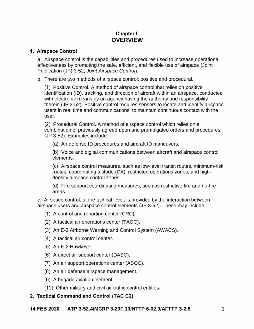
1. Airspace Control
a. Airspace control is the capabilities and procedures used to increase operationaleffectiveness by promoting the safe, efficient, and flexible use of airspace (JointPublication (JP) 3-52, Joint Airspace Control).
b. There are two methods of airspace control: positive and procedural.
Positive Control. A method of airspace control that relies on positiveidentification (ID), tracking, and direction of aircraft within an airspace, conductedwith electronic means by an agency having the authority and responsibilitytherein (JP 3-52). Positive control requires sensors to locate and identify airspaceusers in real time and communications, to maintain continuous contact with theuser.
Procedural Control. A method of airspace control which relies on acombination of previously agreed upon and promulgated orders and procedures(JP 3-52). Examples include:
(a) Air defense ID procedures and aircraft ID maneuvers.
(b) Voice and digital communications between aircraft and airspace controlelements.
(c) Airspace control measures, such as low-level transit routes, minimum-riskroutes, coordinating altitude (CA), restricted operations zones, and high-density airspace control zones.
(d) Fire support coordinating measures, such as restrictive fire and no-fireareas.
c. Airspace control, at the tactical level, is provided by the interaction betweenairspace users and airspace control elements (JP 3-52). These may include:
A control and reporting center (CRC).
A tactical air operations center (TAOC).
An E-3 Airborne Warning and Control System (AWACS).
A tactical air control center.
An E-2 Hawkeye.
A direct air support center (DASC).
An air support operations center (ASOC).
An air defense airspace management.
A brigade aviation element.
Other military and civil air traffic control entities.
2. Tactical Command and Control (TAC C2)
2 ATP 3-52.4/MCRP 3-20F.10/NTTP 6-02.9/AFTTP 3-2.8 14 FEB 2020
a. TAC C2. TAC C2 are airspace control elements under tactical control of the jointforce air component commander or joint force maritime component commander, orcomposite warfare commander (CWC) and use positive and procedural controlmethods to control airspace and manage air operations. Not all airspace controlelements are considered TAC C2.
b. TAC C2 should:
Enable the flow of forces to and from an objective area.
Provide threat warning information and maintain situational awareness (SA) to the primary objective.
Maintain SA of supporting asset status, threat information, and target area information.
Maintain air asset deconfliction to and from a working area.
c. The following are TAC C2-capable entities by Service.
Army. None.
Marine Corps. TAOC and early warning and control.
Navy. E-2 Hawkeye, Ticonderoga-class guided missile cruisers (CGs), Arleigh Burke-class guided missile destroyers (DDGs), Nimitz-class aircraft carriers, nuclear (CVNs), amphibious assault ships (general purpose) (LHAs), Wasp-class amphibious assault ships (multi-purpose) (LHDs), and the San Antonio-class amphibious transport docks (LPDs).
Air Force. AWACS; E-8, Joint Surveillance Target Attack Radar System; and CRC.
3. Assumptions
a. The functional/Service components will adhere to the joint force commander’s(JFC’s) guidance provided through the rules of engagement (ROE), airspace controlplan, airspace control order (ACO), area air defense plan, special instructions(SPINS), and operational tasking (message) (OPTASK).
b. The JFC has delegated commit, ID, and engagement authority to the componentcommanders and authorizes further delegation for mission accomplishment.
c. Component commanders have outlined unambiguous commit, ID, andengagement authority to battle managers through ROE.
d. When executing as a standalone entity, the carrier strike group’s CWC conceptwill independently fulfill the roles in paragraphs a.–c. The officer in tactical commandmay delegate authority to the CWC. Guidance outlined by the CWC will beimplemented by the following principle warfare commanders:
Air and missile warfare commander.
Sea combat commander.
Strike warfare commander.
14 FEB 2020 ATP 3-52.4/MCRP 3-20F.10/NTTP 6-02.9/AFTTP 3-2.8 3
Information operations warfare commander.
e. The ASOC or DASC is the airspace control element for air action short of the firesupport coordination line and below a CA. These volumes of airspace are commonlyreferred to as division assigned airspace or Marine air-ground task force assignedairspace, respectively.

4 ATP 3-52.4/MCRP 3-20F.10/NTTP 6-02.9/AFTTP 3-2.8 14 FEB 2020
This page intentionally left blank.
14 FEB 2020 ATP 3-52.4/MCRP 3-20F.10/NTTP 6-02.9/AFTTP 3-2.8 5
Chapter II TACTICAL ADMINISTRATION (TACADMIN) COMMUNICATION
Note: Information transmitted via a network (NET) (e.g., FRIENDLY, GROUP, or THREAT) and examples of NET transmissions are shown in all capital letters.
1. TACADMIN
a. TACADMIN consists of all processes and procedures that occur in the TAC C2area of responsibility (AOR). It relates to:
Interflight and intraflight procedures.
Airborne mission preparation that directly supports executing the tactical mission objective.
Examples that include: weapon arming, sensor management, personnel recovery package marshaling, and tactical communication checks.
b. TACADMIN does not refer to processes and procedures that coordinate airassets outside the managed AOR. Examples are:
Navigating in civil airspace under civilian air traffic control.
Operating aircraft in the terminal area under military tower or local area air traffic control.
Controlling air traffic to facilitate arrival to, or departure from, an operating base.
c. An example of an exception to 1.b. would be an aircraft launched under scrambleorders (e.g., an alert status) but operating in civil airspace.
2. Communication Priorities
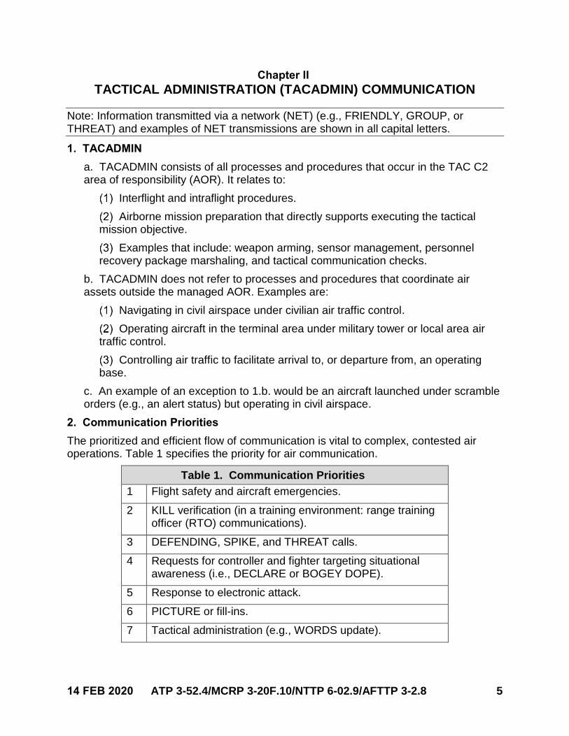
The prioritized and efficient flow of communication is vital to complex, contested air operations. Table 1 specifies the priority for air communication.
Table 1. Communication Priorities
1 Flight safety and aircraft emergencies.
2 KILL verification (in a training environment: range training officer (RTO) communications).
3 DEFENDING, SPIKE, and THREAT calls.
4 Requests for controller and fighter targeting situational awareness (i.e., DECLARE or BOGEY DOPE).
5 Response to electronic attack.
6 PICTURE or fill-ins.
7 Tactical administration (e.g., WORDS update).
6 ATP 3-52.4/MCRP 3-20F.10/NTTP 6-02.9/AFTTP 3-2.8 14 FEB 2020
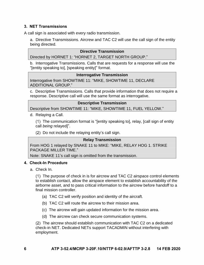
3. NET Transmissions
A call sign is associated with every radio transmission.
a. Directive Transmissions. Aircrew and TAC C2 will use the call sign of the entitybeing directed.
Directive Transmission
Directed by HORNET 1: “HORNET 2, TARGET NORTH GROUP.”
b. Interrogative Transmissions. Calls that are requests for a response will use the“[entity speaking to], [speaking entity]” format.
Interrogative Transmission
Interrogative from SHOWTIME 11: “MIKE, SHOWTIME 11, DECLARE ADDITIONAL GROUP.”
c. Descriptive Transmissions. Calls that provide information that does not require aresponse. Descriptive call will use the same format as interrogative.
Descriptive Transmission
Descriptive from SHOWTIME 11: “MIKE, SHOWTIME 11, FUEL YELLOW.”
d. Relaying a Call.
The communication format is “[entity speaking to], relay, [call sign of entity call being relayed]”.
Do not include the relaying entity’s call sign.
Relay Transmission
From HOG 1 relayed by SNAKE 11 to MIKE: “MIKE, RELAY HOG 1. STRIKE PACKAGE MILLER TIME.”
Note: SNAKE 11’s call sign is omitted from the transmission.
4. Check-In Procedure
a. Check In.
The purpose of check in is for aircrew and TAC C2 airspace control elements to establish contact, allow the airspace element to establish accountability of the airborne asset, and to pass critical information to the aircrew before handoff to a final mission controller.
(a) TAC C2 will verify position and identity of the aircraft.
(b) TAC C2 will route the aircrew to their mission area.
(c) The aircrew will gain updated information for the mission area.
(d) The aircrew can check secure communication systems.
The aircrew should establish communication with TAC C2 on a dedicated check-in NET. Dedicated NETs support TACADMIN without interfering with employment.
14 FEB 2020 ATP 3-52.4/MCRP 3-20F.10/NTTP 6-02.9/AFTTP 3-2.8 7
Once all tactical information has been relayed to the check-in aircraft, TAC C2 will switch the aircrew to the final controller tactical NET.
Note: When checking in with the final controller, the on-coming aircraft is assumed to be TACADMIN complete.
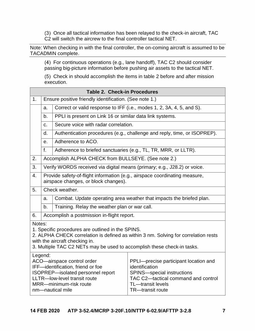
For continuous operations (e.g., lane handoff), TAC C2 should consider passing big-picture information before pushing air assets to the tactical NET.
Check in should accomplish the items in table 2 before and after mission execution.
Table 2. Check-in Procedures
1. Ensure positive friendly identification. (See note 1.)
a. Correct or valid response to IFF (i.e., modes 1, 2, 3A, 4, 5, and S).
b. PPLI is present on Link 16 or similar data link systems.
c. Secure voice with radar correlation.
d. Authentication procedures (e.g., challenge and reply, time, or ISOPREP).
e. Adherence to ACO.
f. Adherence to briefed sanctuaries (e.g., TL, TR, MRR, or LLTR).
2. Accomplish ALPHA CHECK from BULLSEYE. (See note 2.)
3. Verify WORDS received via digital means (primary; e.g., J28.2) or voice.
4. Provide safety-of-flight information (e.g., airspace coordinating measure, airspace changes, or block changes).
5. Check weather.
a. Combat. Update operating area weather that impacts the briefed plan.
b. Training. Relay the weather plan or war call.
6. Accomplish a postmission in-flight report.
Notes: 1. Specific procedures are outlined in the SPINS.2. ALPHA CHECK correlation is defined as within 3 nm. Solving for correlation restswith the aircraft checking in.3. Multiple TAC C2 NETs may be used to accomplish these check-in tasks.
Legend: ACO—airspace control order IFF—identification, friend or foe ISOPREP—isolated personnel report LLTR—low-level transit route MRR—minimum-risk route nm—nautical mile
PPLI—precise participant location and identification SPINS—special instructions TAC C2—tactical command and control TL—transit levels TR—transit route
8 ATP 3-52.4/MCRP 3-20F.10/NTTP 6-02.9/AFTTP 3-2.8 14 FEB 2020
b. Aircrew Check In with TAC C2.
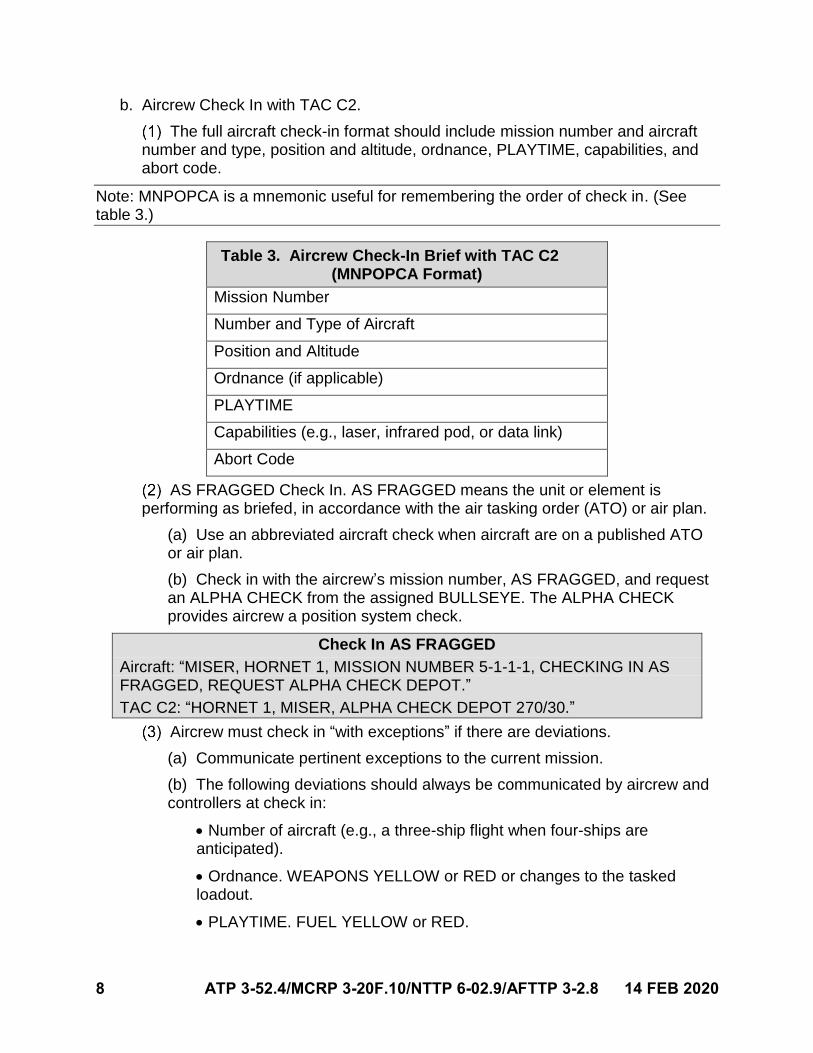
The full aircraft check-in format should include mission number and aircraftnumber and type, position and altitude, ordnance, PLAYTIME, capabilities, andabort code.
Note: MNPOPCA is a mnemonic useful for remembering the order of check in. (See table 3.)
Table 3. Aircrew Check-In Brief with TAC C2 (MNPOPCA Format)
Mission Number
Number and Type of Aircraft
Position and Altitude
Ordnance (if applicable)
PLAYTIME
Capabilities (e.g., laser, infrared pod, or data link)
Abort Code
AS FRAGGED Check In. AS FRAGGED means the unit or element is performing as briefed, in accordance with the air tasking order (ATO) or air plan.
(a) Use an abbreviated aircraft check when aircraft are on a published ATOor air plan.
(b) Check in with the aircrew’s mission number, AS FRAGGED, and requestan ALPHA CHECK from the assigned BULLSEYE. The ALPHA CHECKprovides aircrew a position system check.
Check In AS FRAGGED
Aircraft: “MISER, HORNET 1, MISSION NUMBER 5-1-1-1, CHECKING IN AS FRAGGED, REQUEST ALPHA CHECK DEPOT.”
TAC C2: “HORNET 1, MISER, ALPHA CHECK DEPOT 270/30.”
Aircrew must check in “with exceptions” if there are deviations.
(a) Communicate pertinent exceptions to the current mission.
(b) The following deviations should always be communicated by aircrew andcontrollers at check in:
Number of aircraft (e.g., a three-ship flight when four-ships areanticipated).
Ordnance. WEAPONS YELLOW or RED or changes to the taskedloadout.
PLAYTIME. FUEL YELLOW or RED.
14 FEB 2020 ATP 3-52.4/MCRP 3-20F.10/NTTP 6-02.9/AFTTP 3-2.8 9
Capabilities (e.g., TIMBER SOUR, NEGATIVE JACKAL, or GADGETBENT).
Other pertinent mission-specific exceptions (identify them duringmission planning).
(c) The following is an example of a check in with exceptions.
Example #1: Check In with Exceptions
Aircraft: “MISER, EXXON 1, MISSION NUMBER 6-1-1-1, CHECKING IN WITH EXCEPTIONS, REQUEST ALPHA CHECK BULLSEYE.”
TAC C2: “EXXON 1, MISER, ALPHA CHECK BULLSEYE 270/30, CONTINUE WITH CHECK IN.”
Aircraft: “EXXON 1, OFFLOAD, FRAG MINUS 30 K.”
(d) The following is an example of a check in with controller exceptions:
Example #2: Check-in with TAC C2 Exceptions
Aircraft: “MISER, HORNET 1, MISSION NUMBER 5-1-1-1, CHECKING IN AS FRAGGED, REQUEST ALPHA CHECK BULLSEYE.”
TAC C2: “HORNET 1, MISER, ALPHA CHECK BULLSEYE 270/30.”
Aircraft: “HORNET 1.”
TAC C2: “MISER, TIMBER SOUR.”
Aircraft: “HORNET 1.”
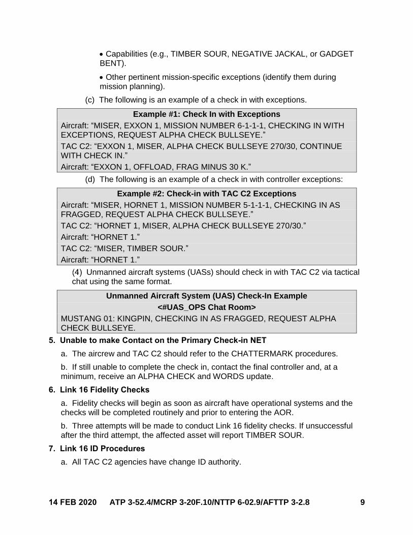
Unmanned aircraft systems (UASs) should check in with TAC C2 via tactical chat using the same format.
Unmanned Aircraft System (UAS) Check-In Example
<#UAS_OPS Chat Room>
MUSTANG 01: KINGPIN, CHECKING IN AS FRAGGED, REQUEST ALPHA CHECK BULLSEYE.
5. Unable to make Contact on the Primary Check-in NET
a. The aircrew and TAC C2 should refer to the CHATTERMARK procedures.
b. If still unable to complete the check in, contact the final controller and, at aminimum, receive an ALPHA CHECK and WORDS update.
6. Link 16 Fidelity Checks
a. Fidelity checks will begin as soon as aircraft have operational systems and thechecks will be completed routinely and prior to entering the AOR.
b. Three attempts will be made to conduct Link 16 fidelity checks. If unsuccessfulafter the third attempt, the affected asset will report TIMBER SOUR.
7. Link 16 ID Procedures
a. All TAC C2 agencies have change ID authority.
10 ATP 3-52.4/MCRP 3-20F.10/NTTP 6-02.9/AFTTP 3-2.8 14 FEB 2020
b. If an ID difference exists on an air track, coordination will be accomplished on thetrack supervision net to verify the correct ID, as in the following example.
Air Track ID Coordination
MOJO: “BARNYARD, MOJO, TRACK 0-1-2-3-3 HOSTILE, TAG FLANKER”
BARNYARD: “BARNYARD, TRACK 0-1-2-3-3 HOSTILE, FLANKER.”
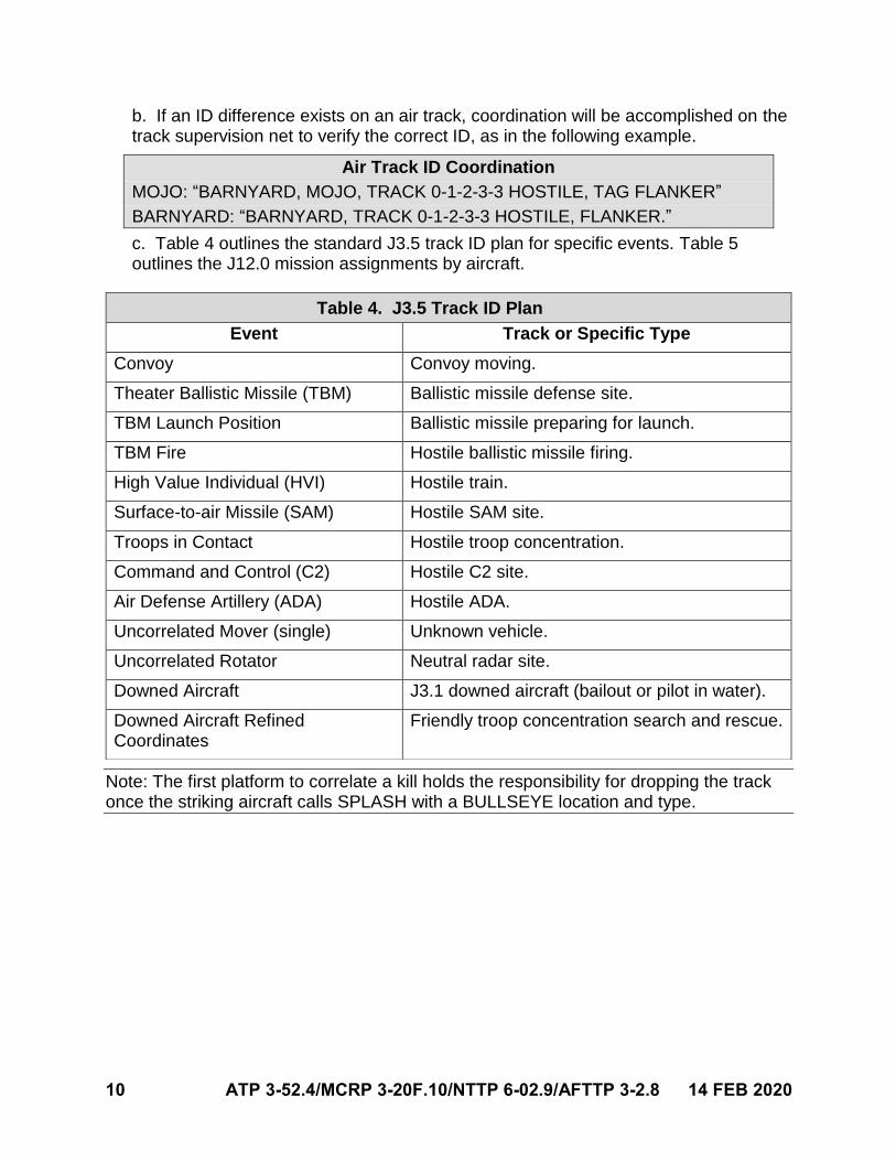
c. Table 4 outlines the standard J3.5 track ID plan for specific events. Table 5outlines the J12.0 mission assignments by aircraft.
Note: The first platform to correlate a kill holds the responsibility for dropping the track once the striking aircraft calls SPLASH with a BULLSEYE location and type.
Table 4. J3.5 Track ID Plan
Event Track or Specific Type
Convoy Convoy moving.
Theater Ballistic Missile (TBM) Ballistic missile defense site.
TBM Launch Position Ballistic missile preparing for launch.
TBM Fire Hostile ballistic missile firing.
High Value Individual (HVI) Hostile train.
Surface-to-air Missile (SAM) Hostile SAM site.
Troops in Contact Hostile troop concentration.
Command and Control (C2) Hostile C2 site.
Air Defense Artillery (ADA) Hostile ADA.
Uncorrelated Mover (single) Unknown vehicle.
Uncorrelated Rotator Neutral radar site.
Downed Aircraft J3.1 downed aircraft (bailout or pilot in water).
Downed Aircraft Refined Coordinates
Friendly troop concentration search and rescue.
14 FEB 2020 ATP 3-52.4/MCRP 3-20F.10/NTTP 6-02.9/AFTTP 3-2.8 11
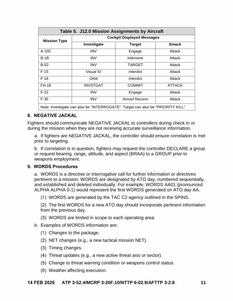
Table 5. J12.0 Mission Assignments by Aircraft
Mission Type Cockpit Displayed Messages
Investigate Target Smack
A-10C INV Engage Attack
B-1B INV Intervene Attack
B-52 INV TARGET Attack
F-15 Visual ID Interdict Attack
F-16 Orbit Interdict Attack
FA-18 INVSTGAT COMMIT ATTACK
F-22 INV Engage Attack
F-35 INV Armed Reconn Attack
Note: Investigate can also be “INTERROGATE”. Target can also be “PRIORITY KILL”.
8. NEGATIVE JACKAL
Fighters should communicate NEGATIVE JACKAL to controllers during check in or during the mission when they are not receiving accurate surveillance information.
a. If fighters are NEGATIVE JACKAL, the controller should ensure correlation is metprior to targeting.
b. If correlation is in question, fighters may request the controller DECLARE a groupor request bearing, range, altitude, and aspect (BRAA) to a GROUP prior toweapons employment.
9. WORDS Procedures
a. WORDS is a directive or interrogative call for further information or directivespertinent to a mission. WORDS are designated by ATO day, numbered sequentially,and established and deleted individually. For example, WORDS AA01 (pronouncedALPHA ALPHA 0-1) would represent the first WORDS generated on ATO day AA.
WORDS are generated by the TAC C2 agency outlined in the SPINS.
The first WORDS for a new ATO day should incorporate pertinent information from the previous day.
WORDS are limited in scope to each operating area.
b. Examples of WORDS information are:
Changes to the package.
NET changes (e.g., a new tactical mission NET).
Timing changes.
Threat updates (e.g., a new active threat axis or sector).
Change to threat warning condition or weapons control status.
Weather affecting execution.
12 ATP 3-52.4/MCRP 3-20F.10/NTTP 6-02.9/AFTTP 3-2.8 14 FEB 2020
c. TAC C2 will relay WORDS to all assets in the operating area, the joint airoperations center (JAOC), tactical air command center, and appropriate CWC.
New WORDS will be relayed by TAC C2.
TAC C2 will use digital means (e.g., J28.2), to the maximum extent possible, when passing WORDS to air assets.
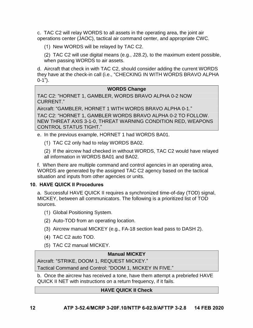
d. Aircraft that check in with TAC C2, should consider adding the current WORDSthey have at the check-in call (i.e., “CHECKING IN WITH WORDS BRAVO ALPHA0-1”).
WORDS Change
TAC C2: “HORNET 1, GAMBLER, WORDS BRAVO ALPHA 0-2 NOW CURRENT.”
Aircraft: “GAMBLER, HORNET 1 WITH WORDS BRAVO ALPHA 0-1.”
TAC C2: “HORNET 1, GAMBLER WORDS BRAVO ALPHA 0-2 TO FOLLOW. NEW THREAT AXIS 3-1-0, THREAT WARNING CONDITION RED, WEAPONS CONTROL STATUS TIGHT.”
e. In the previous example, HORNET 1 had WORDS BA01.
TAC C2 only had to relay WORDS BA02.
If the aircrew had checked in without WORDS, TAC C2 would have relayed all information in WORDS BA01 and BA02.
f. When there are multiple command and control agencies in an operating area,WORDS are generated by the assigned TAC C2 agency based on the tacticalsituation and inputs from other agencies or units.
10. HAVE QUICK II Procedures
a. Successful HAVE QUICK II requires a synchronized time-of-day (TOD) signal,MICKEY, between all communicators. The following is a prioritized list of TODsources.
Global Positioning System.
Auto-TOD from an operating location.
Aircrew manual MICKEY (e.g., FA-18 section lead pass to DASH 2).
TAC C2 auto TOD.
TAC C2 manual MICKEY.
Manual MICKEY
Aircraft: “STRIKE, DOOM 1, REQUEST MICKEY.”
Tactical Command and Control: “DOOM 1, MICKEY IN FIVE.”
b. Once the aircrew has received a tone, have them attempt a prebriefed HAVEQUICK II NET with instructions on a return frequency, if it fails.
HAVE QUICK II Check
14 FEB 2020 ATP 3-52.4/MCRP 3-20F.10/NTTP 6-02.9/AFTTP 3-2.8 13
Aircraft: “DOOM 1, GOOD MICKEY.”
TAC C2: “DOOM 1, STRIKE, PUSH ACTIVE TAD 57 POGO.”
Note: AWACS manual MICKEY is single tone only. Expect a multiple tone MICKEY from other TAC C2 agencies.
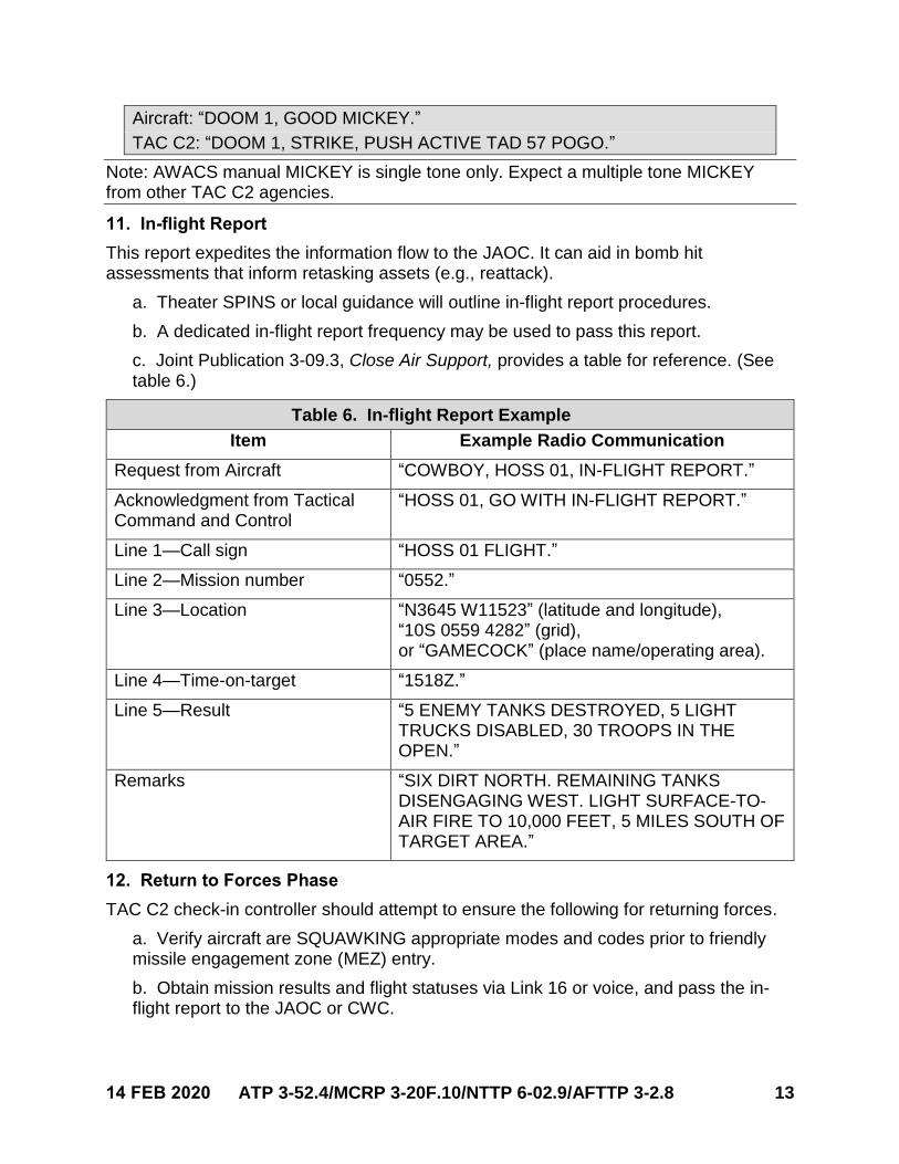
11. In-flight Report
This report expedites the information flow to the JAOC. It can aid in bomb hit assessments that inform retasking assets (e.g., reattack).
a. Theater SPINS or local guidance will outline in-flight report procedures.
b. A dedicated in-flight report frequency may be used to pass this report.
c. Joint Publication 3-09.3, Close Air Support, provides a table for reference. (Seetable 6.)
Table 6. In-flight Report Example
Item Example Radio Communication
Request from Aircraft “COWBOY, HOSS 01, IN-FLIGHT REPORT.”
Acknowledgment from Tactical Command and Control
“HOSS 01, GO WITH IN-FLIGHT REPORT.”
Line 1—Call sign “HOSS 01 FLIGHT.”
Line 2—Mission number “0552.”
Line 3—Location “N3645 W11523” (latitude and longitude), “10S 0559 4282” (grid), or “GAMECOCK” (place name/operating area).
Line 4—Time-on-target “1518Z.”
Line 5—Result “5 ENEMY TANKS DESTROYED, 5 LIGHT TRUCKS DISABLED, 30 TROOPS IN THE OPEN.”
Remarks “SIX DIRT NORTH. REMAINING TANKS DISENGAGING WEST. LIGHT SURFACE-TO-AIR FIRE TO 10,000 FEET, 5 MILES SOUTH OF TARGET AREA.”
12. Return to Forces Phase
TAC C2 check-in controller should attempt to ensure the following for returning forces.
a. Verify aircraft are SQUAWKING appropriate modes and codes prior to friendlymissile engagement zone (MEZ) entry.
b. Obtain mission results and flight statuses via Link 16 or voice, and pass the in-flight report to the JAOC or CWC.
14 ATP 3-52.4/MCRP 3-20F.10/NTTP 6-02.9/AFTTP 3-2.8 14 FEB 2020
c. Execute Wounded Bird, battle damage, or hung ordnance notification proceduresin accordance with theater directives.
FORCE TELL the track until directed by higher headquarters.
Obtain call sign, status, and track number of the aircraft.
Monitor and track the aircraft until it is out of radar coverage or until it is under recovery base approach control to ensure a safe return.
Prepare to coordinate combat search and rescue operations.
d. Pass information on HOME PLATE weather and operational status (e.g., runwayclosures or recovery procedures).
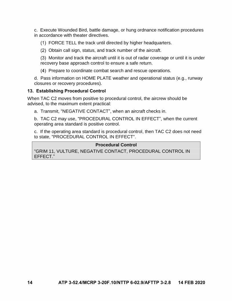
13. Establishing Procedural Control
When TAC C2 moves from positive to procedural control, the aircrew should be advised, to the maximum extent practical:
a. Transmit, “NEGATIVE CONTACT”, when an aircraft checks in.
b. TAC C2 may use, “PROCEDURAL CONTROL IN EFFECT”, when the currentoperating area standard is positive control.
c. If the operating area standard is procedural control, then TAC C2 does not needto state, “PROCEDURAL CONTROL IN EFFECT“.
Procedural Control
“GRIM 11, VULTURE, NEGATIVE CONTACT, PROCEDURAL CONTROL IN EFFECT.”
14 FEB 2020 ATP 3-52.4/MCRP 3-20F.10/NTTP 6-02.9/AFTTP 3-2.8 15
Chapter III
FORCE PACKAGING AND DIRECT AIR SUPPORT COORDINATION
Missions that involve a mission commander (MC) require extensive coordination to execute. The MC and TAC C2 should establish a plan to receive the LOWDOWN, obtain force package accountability before and after mission execution, establish backup communication plans, and establish air communication contracts. This section, and the following chapters, establish baseline tactics, techniques, and procedures for these items.
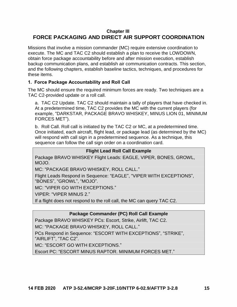
1. Force Package Accountability and Roll Call
The MC should ensure the required minimum forces are ready. Two techniques are a TAC C2-provided update or a roll call.
a. TAC C2 Update. TAC C2 should maintain a tally of players that have checked in.At a predetermined time, TAC C2 provides the MC with the current players (forexample, “DARKSTAR, PACKAGE BRAVO WHISKEY, MINUS LION 01, MINIMUMFORCES MET”).
b. Roll Call. Roll call is initiated by the TAC C2 or MC, at a predetermined time.Once initiated, each aircraft, flight lead, or package lead (as determined by the MC)will respond with call sign in a predetermined sequence. As a technique, thissequence can follow the call sign order on a coordination card.
Flight Lead Roll Call Example
Package BRAVO WHISKEY Flight Leads: EAGLE, VIPER, BONES, GROWL, MOJO.
MC: “PACKAGE BRAVO WHISKEY, ROLL CALL.”
Flight Leads Respond in Sequence: “EAGLE”, “VIPER WITH EXCEPTIONS”, “BONES”, “GROWL”, “MOJO”.
MC: “VIPER GO WITH EXCEPTIONS.”
VIPER: “VIPER MINUS 2.”
If a flight does not respond to the roll call, the MC can query TAC C2.
Package Commander (PC) Roll Call Example
Package BRAVO WHISKEY PCs: Escort, Strike, Airlift, TAC C2.
MC: “PACKAGE BRAVO WHISKEY, ROLL CALL.”
PCs Respond in Sequence: “ESCORT WITH EXCEPTIONS”, “STRIKE”, “AIRLIFT”, “TAC C2”.
MC: “ESCORT GO WITH EXCEPTIONS.”
Escort PC: “ESCORT MINUS RAPTOR. MINIMUM FORCES MET.”
16 ATP 3-52.4/MCRP 3-20F.10/NTTP 6-02.9/AFTTP 3-2.8 14 FEB 2020
c. Times to consider initiating a roll call.
Post LOWDOWN.
When there are updated WORDS.
When forces completed their mission and are returning.
When there is a suspected or known loss of an air asset.
When there is a timing change to the mission.
When the weather plan changes.
When there is key mission enabler fallout.
Post CHATTERMARK on a new NET.
2. LOWDOWN
LOWDOWN is a request for the tactical ground picture in an area of interest. TAC C2 should correlate all factor ground systems using the BULLSEYE format.
Note: When communicating with United States (US) Army or US Marine Corps rotary-wing and UAS, pass surface threat information in military grid reference system (MGRS), if known. Attempt to provide at least a 6-digit grid.
a. LOWDOWN is passed at a briefed time (e.g., 5 minutes prior to missionexecution) and is immediately followed by a roll call.
b. An aircrew may request LOWDOWN but should do so in accordance withcommunication priorities (allow 30 to 60 seconds for TAC C2 to compileLOWDOWN).
c. For aircraft not in the tactical NET during the initial LOWDOWN, it is passed uponinitial check in as part of the WORDS.
d. LOWDOWN may not be required for each mission set, such as when fighters areconducting a defensive counterair mission in a permissive environment.
e. LOWDOWN is passed digitally, via Link 16 and tactical chat, or verbally. In orderof priority (unless otherwise briefed), the LOWDOWN should include:
(a) Strategic surface-to-air missile (SAM) systems ACTIVE or AWAKE withinthe last 8 hours that were not a part of the briefed threat defensive missileorder of battle. Expect strategic SAMs references using mission planningnaming conventions.
(b) Tactical SAMs ACTIVE or AWAKE within the last hour (e.g., enemy navaltactical SAM).
(c) MOVERS/ROTATORS meeting briefed reporting criteria.
(d) Additional entities, events, or areas of interest applicable to the mission.
14 FEB 2020 ATP 3-52.4/MCRP 3-20F.10/NTTP 6-02.9/AFTTP 3-2.8 17
LOWDOWN Example
“GOLIATH, LOWDOWN. TWO ACTIVE BULLSEYE 090/10, EIGHT ACTIVE BULLSEYE 085/13, SIX AWAKE BULLSEYE 075/14, ROTATOR BULLSEYE 260/15. HOSTILE CONVOY BULLSEYE 270/10 TRACK EAST.”
f. For tactical SAMs and MOVERS, the order of dissemination is:
Closest MEZ to friendly forces.
Closest MEZ to friendly axis of attack or ingress routes.
Most lethal.
3. Timing Changes
a. ROLEX. Timeline adjustment in minutes; always referenced from originalpreplanned mission execution time.
ROLEX is used to adjust the mission timing as a whole.
PLUS is assumed.
If a time on target (TOT) window extension is required to adhere to the ROLEX, TAC C2 agencies should request approval and pass it to the affected flights.
ROLEX is made in 5-minute increments and is not additive.
ROLEX Example
Original package WHISKEY ALPHA mission start time: 1500Z.
“COWBOY, PACKAGE WHISKEY ALPHA, ROLEX 10.”
New mission start time: 1510Z.
“COWBOY, PACKAGE WHISKEY ALPHA, ROLEX 15.”
New mission start time: 1515Z.
b. SLIP. SLIP is time delay to individual flight or element event. SLIP is not additive.
SLIP Example
Original TOT: 1500Z.
“HARDROCK, HOSS 1, SLIP TOT 6 MINUTES.”
New TOT: 1506Z.
“HARDROCK, HOSS 1, SLIP TOT 9 MINUTES.”
New TOT: 1509Z.
c. For changes to training vulnerability times, MCs and TAC C2 should use plainlanguage to avoid confusion.
4. CHATTERMARK Procedures
a. CHATTERMARK procedures are established to transition from primary toalternate tactical NETs.
b. The CHATTERMARK plan should:
18 ATP 3-52.4/MCRP 3-20F.10/NTTP 6-02.9/AFTTP 3-2.8 14 FEB 2020
Provide alternate NETs, which reside in different frequency bands.
Prioritize secure, frequency-hopping forms of radio communication. (Tailor them based on threat communication jamming capabilities.)
Establish a “get well” NET, such as the TAC C2 check-in NET. If the aircrew are unsure of the current tactical NET, they can switch to the “get well” NET to receive direction from TAC C2.
Outline the criteria and authority for executing a CHATTERMARK. This resides with MC or a designated PC. Degradation on the primary tactical NET due to communications jamming or system limitations for the aircrew or controller (e.g., UNABLE HAVE QUICK) are the most common reasons to CHATTERMARK.
c. Request a CHATTERMARK via a “Request POGO [NET name in color andnumber]” (e.g., INDIGO 03).
d. If a CHATTERMARK is directed, all assets will switch to the planned alternateNET, in accordance with the CHATTERMARK plan, and await a roll call.
TAC C2 or MC will repeat CHATTERMARK three times on the primary tactical NET prior to switching to the alternate tactical NET and publish a digital message.
If able, TAC C2 will simulcast on the old, affected NET and the new NET.
TAC C2 simulcast will continue until force accountability is confirmed on the new NET.
Force Accountability on New NET.
(a) Flight leads or PCs, per mission plan, should communicate their call signon the new NET. TAC C2 should only acknowledge if communication timeallows, in accordance with communication priorities.
(b) TAC C2 should note accountability as players check in. TAC C2 willaccomplish a ROLL CALL if needed.
(c) TAC C2 should communicate “NET SWEET” on the new NET once allplayers have checked in.
CHATTERMARK Example
Primary NET degradation is noted by TAC C2.
Transmitting on the Old NET:
MISER (TAC C2): “CHATTERMARK, CHATTERMARK, CHATTERMARK.”
Transmitting on New NET:
Flight Leads: “EAGLE.” “RAPTOR.” “HORNET.” “GROWLER.”
MISER: “NET SWEET.”
14 FEB 2020 ATP 3-52.4/MCRP 3-20F.10/NTTP 6-02.9/AFTTP 3-2.8 19
5. Battlespace Handover Procedures
a. A positive handoff is required by the off-going and on-coming lane commander.
PUSH. On-coming aircraft may enter the operating area (e.g., defensivecounterair lane).
COMMIT. When directed by the off-going aircraft, this call transitionscommunication priority to the on-coming aircraft to take over as the lanecommander.
Lane Commander Transition. The off-going lane commander will get positive communication lane handoff to the on-coming lane commander.
Lane Handoff
Off-going Lane Commander: “HORNET 1, YOU HAVE THE LANE.”
On-coming Lane Commander: “HORNET 1, HAS THE LANE.”
b. The off-going lane commander will pass critical mission information to TAC C2 inaccordance with theater in-flight report procedures.
TAC C2 will use this information to update WORDS or LOWDOWN.
TAC C2 should pass big-picture information to the oncoming lane commander before pushing assets to the tactical frequency.
(a) Example. “TEN GROUPS, TWO PACKAGES, NORTH PACKAGETARGETED BY SWEEP. SOUTH PACKAGE TARGETED BY BIG STICK.”
(b) Example. “TWELVE GROUPS, LEADING EDGE FOUR GROUP WALLTARGETED BY RAPTOR.”
c. TAC C2 will relay critical information affecting off-going aircraft return-to-baseprocedures. Pass information on weather and airfield issues (e.g., runway closures).
d. Refer to other mission-specific publications for positive handoff of missioncommand roles (e.g., strike coordination and reconnaissance or close air support).
6. YELLOW and RED Statuses
a. Unless otherwise briefed, YELLOW and RED are defined as:
YELLOW: One engagement option available (per type, model, and/or series (T/M/S) or mission design series (MDS) specific primary mission set).
RED: No engagement option is available due to either a FUEL, WEAPON, or sensor limitation.
b. Aircraft must relay when they are YELLOW to TAC C2.
c. TAC C2 is responsible to coordinate on-station relief prior to the aircraftcommunicating RED on the primary NET.

20 ATP 3-52.4/MCRP 3-20F.10/NTTP 6-02.9/AFTTP 3-2.8 14 FEB 2020
This page intentionally left blank.
14 FEB 2020 ATP 3-52.4/MCRP 3-20F.10/NTTP 6-02.9/AFTTP 3-2.8 21
Chapter IV AIR-TO-AIR (A/A) COMMUNICATION FUNDAMENTALS
Note: For the purpose of this publication, controller is a general term used to define the individual providing tactical control of an intercept, or mission. The term “fighter” is used throughout this chapter. Fighter information applies to any aircraft capable of employing A/A ordnance. Controller and fighter are used independent of platform or Service.
1. COMMUNICATION FUNDAMENTALS
a. A GROUP is the way TAC C2 and aircraft describe other air assets, and is usedto describe unknown or enemy aircraft.
b. The PICTURE establishes a common tactical air image and describes the spatialrelationship of GROUPs.
2. GROUP
a. A GROUP is any number of air CONTACTs within 3 nautical miles (nm) inazimuth and range of each other.
CONTACT is an individual radar return within a GROUP.
SINGLE CONTACT is the assumed STRENGTH for all GROUPs. More CONTACTs are specified (e.g., SINGLE GROUP TWO CONTACTs).
Note: The controlling platform’s capabilities and limitations will determine if controllers will communicate the number of CONTACTs in a GROUP. If unable to determine the number of CONTACTs, but assessed to be three or more, controllers will only use the fill-in, HEAVY.
b. GROUPs are distinguished by either a unique name or unique position.
There are four unique naming conventions used:
(a) Cardinal Relationship (e.g., NORTH GROUP, SOUTH GROUP).
(b) Range Relationship. Relationship relative to a specific aircraft perspective(e.g. LEAD GROUP, TRAIL GROUP).
(c) Combined Cardinal and Range Relationship (e.g., NORTH LEADGROUP).
(d) Descriptive Name (e.g., SINGLE GROUP, ADDITIONAL GROUP, POP-UP GROUP).
Unique Position Reference. GROUPs can be distinguished using unique position names such as BULLSEYE, bearing, range, altitude, and aspect (BRAA), or geographic reference (GEOREF).
22 ATP 3-52.4/MCRP 3-20F.10/NTTP 6-02.9/AFTTP 3-2.8 14 FEB 2020
3. Core Information Format
Controllers and air assets will use the core information format to communicate GROUPs:
a. Total Number of GROUPs.
b. GROUP Location (i.e., BULLSEYE, BRAA, or GEOREF).
c. Altitude (rounded to the nearest thousands of feet).
d. Track direction or specific aspect (e.g., cardinal/sub-cardinal orHOT/FLANK/BEAM/DRAG).
e. Declaration.
f. Fill-ins (as appropriate).
4. GROUP Location (i.e., BULLSEYE, BRAA, or GEOREF)
a. BULLSEYE (Primary Method to Communicate the GROUP Location).
BULLSEYE is an established reference point from which the position of an object can be referred to by bearing (magnetic) and range (nm).
BULLSEYE information is rounded to the nearest degree and nm.
(a) For example, BULLSEYE 225/30 means 30 nm on a magnetic bearing of225 degrees from the BULLSEYE location.
(b) It is communicated “two-two-five thirty”.
(c) If an aircraft is within 5 nm of BULLSEYE, controllers may describe theGROUP as AT BULLSEYE unless that GROUP is to be targeted.
GROUP AT BULLSEYE Example
“SHOWTIME 11, LEAD GROUP, AT BULLSEYE, THIRTY-NINE THOUSAND, TRACK NORTH, HOSTILE.”
Use the code name for BULLSEYE when directed by SPINS.
BULLSEYE Code Name Example
BULLSEYE Code Name: ROCK.
“MIKE, SOUTH GROUP, ROCK 255/29, THIRTY-NINE THOUSAND, CAP, HOSTILE.”
BULLSEYE will not be truncated to “bull” to avoid it being misinterpreted as “BRAA”.
b. BRAA.
BRAA information for bearing and range are rounded to the nearest degree and nm.
(a) BRAA calls provide target bearing, range, altitude, and aspect relative tothe specified FRIENDLY aircraft.
14 FEB 2020 ATP 3-52.4/MCRP 3-20F.10/NTTP 6-02.9/AFTTP 3-2.8 23
For example, BRAA 225/10 means 10 nm on a magnetic bearing of 225degrees from the FRIENDLY aircraft.
It is communicated “two-two-five ten.”
Controllers should use the BRAA format if the information being communicated pertains only to one specific aircraft or if responding directly to the following fighter requests: BRAA, BOGEY DOPE, and SNAPLOCK.
Controllers will also use the BRAA format when providing a THREAT call to an aircraft.
THREAT Call Example
“SHOWTIME 11, LEAD GROUP, THREAT BRAA 270/55, THIRTY-NINE THOUSAND, FLANK NORTHEAST, HOSTILE.”
c. GEOREF Point.
The controller may use a GEOREF to provide the approximate location of a GROUP.
Examples of GEOREFS may be a prominent natural feature, such a mountain peak, or a prominent manmade structure, such as an airfield.
Geographic Reference Example
Prominent Enemy Airfield Code Name: DEPOT.
“SHOWTIME 11, LEAD GROUP, AT DEPOT, THIRTY-NINE THOUSAND, CAP, HOSTILE.”
5. GROUP Altitude
a. Fighters and controllers will round altitudes to the nearest thousand feet indicatedon their system.
b. Controllers will not use LOW or HIGH in place of the altitude and will use“ALTITUDE UNKNOWN” if the controlling platform is capable of determining altitude,but a solution is not available.
c. Controllers will omit altitude from the communication format if the controllingplatform is not capable of generating an altitude.
d. Altitude STACKS.
Altitude separation in a GROUP greater than or equal to 10,000 feet are voiced as a STACK stating the higher altitude first, then the lower altitude.
Altitude Stack Example
“SHOWTIME 11, NORTH GROUP BRAA 300/32, STACK THIRTY-TWO THOUSAND AND EIGHT THOUSAND, HOT, HOSTILE, TWO CONTACTS, FLANKER.”
If the STACK has two or more altitude separations of 10,000 feet within the group, then controllers may voice the number of CONTACTs HIGH/MEDIUM/LOW or at specific altitudes as fill-in information.
24 ATP 3-52.4/MCRP 3-20F.10/NTTP 6-02.9/AFTTP 3-2.8 14 FEB 2020
HIGH/MEDIUM/LOW Altitude Stack Example
“HARDROCK, NORTH GROUP UTAH 300/12, STACK THIRTY-FIVE THOUSAND and TWENTY-FOUR THOUSAND, TRACK WEST, HOSTILE, HEAVY, THREE CONTACTS, TWO HIGH, ONE LOW.”
Specific Altitude Example
“BARNYARD, ADDITIONAL GROUP PEAK 200/12, STACK THIRTY-FIVE THOUSAND, TWENTY-FOUR THOUSAND and TEN THOUSAND, TRACK WEST, HOSTILE, HEAVY, THREE CONTACTS.”
6. Track Direction and Specific Aspect
a. Track direction will always be used to communicate a GROUP via BULLSEYEand communicated with the cardinal or sub-cardinal direction (e.g., TRACKNORTHEAST, TRACK SOUTH).
b. PICTURE Exception.
If all GROUPs in a traditional PICTURE, LEADING EDGE, or PACKAGE are tracking the same direction, controllers should use the term TRACK with the cardinal direction following the PICTURE label.
GROUPs TRACK the Same Direction Example
“MIKE, TWO GROUPS RANGE 30, TRACK EAST. LEAD GROUP ROCK 145/60, THIRTY-FIVE THOUSAND, HOSTILE. TRAIL GROUP TWENTY THOUSAND, HOSTILE.”
If amplifying the PICTURE with TRACK direction, controllers should not provide a track direction for every GROUP in the picture.
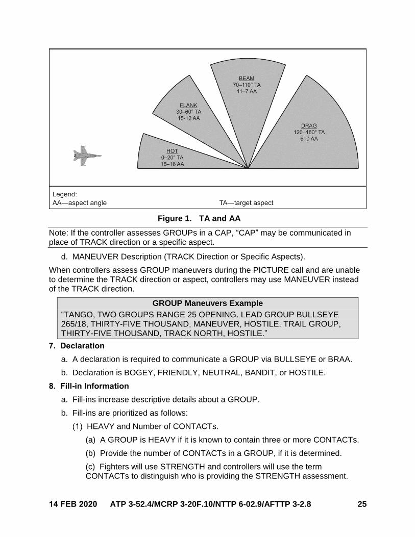
c. Specific aspects, as depicted in figure 1, are used when correlating a group to aspecific fighter and will be used when communicating with the BRAA format.
Specific aspects (i.e., HOT, FLANK, BEAM, and DRAG) are determined by the GROUP target aspect (TA) or aspect angle (AA) to the fighter.
FLANK, BEAM, DRAG are accompanied with a cardinal/sub-cardinal direction (e.g., DRAG WEST).
14 FEB 2020 ATP 3-52.4/MCRP 3-20F.10/NTTP 6-02.9/AFTTP 3-2.8 25
Figure 1. TA and AA
Note: If the controller assesses GROUPs in a CAP, “CAP” may be communicated in place of TRACK direction or a specific aspect.
d. MANEUVER Description (TRACK Direction or Specific Aspects).
When controllers assess GROUP maneuvers during the PICTURE call and are unable to determine the TRACK direction or aspect, controllers may use MANEUVER instead of the TRACK direction.
GROUP Maneuvers Example
“TANGO, TWO GROUPS RANGE 25 OPENING. LEAD GROUP BULLSEYE 265/18, THIRTY-FIVE THOUSAND, MANEUVER, HOSTILE. TRAIL GROUP, THIRTY-FIVE THOUSAND, TRACK NORTH, HOSTILE.”
7. Declaration
a. A declaration is required to communicate a GROUP via BULLSEYE or BRAA.
b. Declaration is BOGEY, FRIENDLY, NEUTRAL, BANDIT, or HOSTILE.
8. Fill-in Information
a. Fill-ins increase descriptive details about a GROUP.
b. Fill-ins are prioritized as follows:
HEAVY and Number of CONTACTs.
(a) A GROUP is HEAVY if it is known to contain three or more CONTACTs.
(b) Provide the number of CONTACTs in a GROUP, if it is determined.
(c) Fighters will use STRENGTH and controllers will use the termCONTACTs to distinguish who is providing the STRENGTH assessment.
26 ATP 3-52.4/MCRP 3-20F.10/NTTP 6-02.9/AFTTP 3-2.8 14 FEB 2020
CONTACTs versus STRENGTH Example
Controller: “CLUBHOUSE, WEST GROUP FOUR CONTACTS.”
Fighter: “SHOWTIME 12, EAST GROUP STRENGTH THREE.”
Platform/Type. Controllers will provide an aircraft platform (e.g., fighter or bomber) or type (e.g., MiG-29 or J-11B) with PICTURES and requests for SA to that GROUP.
HIGH. Contact is greater than 40,000 feet mean sea level. HIGH can be used as a fill-in.
FAST or VERY FAST. These definitions are provided as references.
(a) FAST. Target speed of 600–900 knots ground speed or 1.0–1.5 mach.
(b) VERY FAST. Target speed greater than 900 knots or 1.5 mach.
Fill-ins Example
“DRAGNET, NORTH GROUP, BULLSEYE 270/15, FORTY-TWO THOUSAND, TRACK WEST, HOSTILE, HIGH, VERY FAST.”
UNTARGETED.
(a) If a GROUP has not been targeted inside the briefed targeting range,then the controller should use the fill-in UNTARGETED. Tactics selection perthe fighter’s targeting game plan will determine the applicability ofUNTARGETED.
UNTARGETED Example
“DRAGNET, NORTH GROUP, BULLSEYE 270/15, TWENTY THOUSAND, TRACK WEST, HOSTILE, UNTARGETED.”
Note: US Navy assets will issue directive targeting to fighters who are inside the targeting range, if the controller assesses targeting that has not been issued or is not sound.
(b) UNTARGETED may be used as a fill-in to describe priority GROUPs thatare a risk to a mission or force (e.g., an enemy approaching the mission failline).
(c) If a fighter calls TARGETED or acknowledges directive targeting,contracts for UNTARGETED and THREAT calls are cancelled.
TARGETED BY, LEANING ON, THREAT TO.
(a) TARGETED BY provides SA that a GROUP is already TARGETED.
TARGETED BY Example
Fighter: “MIKE, EAGLE 11, DECLARE NORTH GROUP.”
Controller: “EAGLE 11, NORTH GROUP, BULLSEYE 285/35, TWENTY THOUSAND, TRACK EAST, HOSTILE, TARGETED BY HORNET 2.”
(b) LEANING ON aids in assessing which aircraft a THREAT is possiblytargeting.
14 FEB 2020 ATP 3-52.4/MCRP 3-20F.10/NTTP 6-02.9/AFTTP 3-2.8 27
Making an accurate LEANING ON assessment is increasingly difficultwith improved THREAT capabilities. For example, a FLANK or BEAMTHREAT could be employing ordnance while LEANING ON anotherfighter.
LEANING ON assessments are reserved for when fighters are in COLDoperations.
LEANING ON Example
“DARKLORD, SINGLE GROUP ROCK 256/49, THIRTY-NINE THOUSAND, TRACK EAST, HOSTILE, FLANKER, LEANING ON EAGLE 1.”
(c) THREAT TO is reserved for when fighters are in COLD operations and afighter does not meet the minimum recommit range.
THREAT TO Example
“MIKE, TWO GROUPS AZIMUTH 25. NORTH GROUP, ROCK 285/35, THIRTY-FIVE THOUSAND, TRACK EAST, HOSTILE, THREAT TO HORNET 1. SOUTH GROUP THIRTY THOUSAND, TRACK EAST, HOSTILE.”
IMPACT (PLUS Time of Flight).
(a) Controllers will add the IMPACT time to any FRIENDLY surface-to-air(S/A) fires when operating in a joint engagement zone or fighter engagementzone.
IMPACT Example 1
“GAMBLER, BIG STICK AWAY TRAIL GROUP, IMPACT 1 PLUS 15.”
(b) The IMPACT time is used to aid follow-on fighter targeting, decisionmaking, and ensure fires deconfliction.
(c) IMPACT time can be used as a PICTURE fill-in as well.
IMPACT Example 2
“GAMBLER, TRAIL GROUP ROCK 180/85, THIRTY THOUSAND, TRACK NORTH, HOSTILE, IMPACT 1 PLUS 15.”
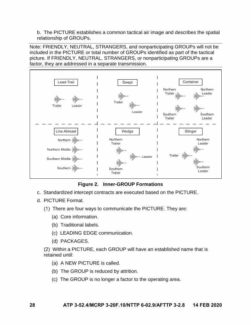
c. Inner GROUP Formations.
When describing an inner GROUP formation, controllers and fighters will use the terms described in Figure 2, Inner Group Formations.
Controllers and fighters should name the inner GROUP formation when this call will enhance fighter targeting or SA approaching the merge.
Inner GROUP formations should be used inside expected radar resolution ranges.
9. PICTURE
a. PICTURE is a request to provide information pertinent to the mission in aBULLSEYE format, unless briefed otherwise.
28 ATP 3-52.4/MCRP 3-20F.10/NTTP 6-02.9/AFTTP 3-2.8 14 FEB 2020
b. The PICTURE establishes a common tactical air image and describes the spatialrelationship of GROUPs.
Note: FRIENDLY, NEUTRAL, STRANGERS, and nonparticipating GROUPs will not be included in the PICTURE or total number of GROUPs identified as part of the tactical picture. If FRIENDLY, NEUTRAL, STRANGERS, or nonparticipating GROUPs are a factor, they are addressed in a separate transmission.
Figure 2. Inner-GROUP Formations
c. Standardized intercept contracts are executed based on the PICTURE.
d. PICTURE Format.
There are four ways to communicate the PICTURE. They are:
(a) Core information.
(b) Traditional labels.
(c) LEADING EDGE communication.
(d) PACKAGES.
Within a PICTURE, each GROUP will have an established name that is retained until:
(a) A NEW PICTURE is called.
(b) The GROUP is reduced by attrition.
(c) The GROUP is no longer a factor to the operating area.
14 FEB 2020 ATP 3-52.4/MCRP 3-20F.10/NTTP 6-02.9/AFTTP 3-2.8 29
10. Anchoring a PICTURE
The following are ways anchoring uses the same priorities as PICTURE.
a. Anchoring is prioritized communication of GROUPs.
An anchor is a BULLSEYE used to establish the PICTURE and aid in fighter targeting.
Outrigger GROUPs will be anchored with BULLSEYE if the GROUPs are outside 10 nm in azimuth.
Geographic boundaries and the targeting game plan will dictate the maximum GROUPs that are anchored (e.g., dual-lane defensive counterair with a fighter engagement zone that has a defined azimuth boundary).
b. Force and Mission Anchoring Priority.
Anchoring priorities can shift from the force (e.g., fighters) to the mission. Forexample, an enemy striker approaches a mission fail line and puts the mission atrisk. In this case, the enemy striker may be the anchoring priority.
Anchoring priority for risk to mission can take priority over risk to force.
c. When risk to force is a higher priority than risk to the mission, controllers willanchor GROUPs referring to the following priorities:
The threat that is closest to fighters.
The most capable threat (based on combat ID, declaration, aircraft type, flight profile).
HIGH GROUPs.
The largest GROUP STRENGTH.
11. Core Information Concerning a PICTURE
a. This label is primarily used:
Pre-COMMIT.
If the PICTURE does not meet a traditional or LEADING EDGE label.
If there are three GROUPs or fewer.
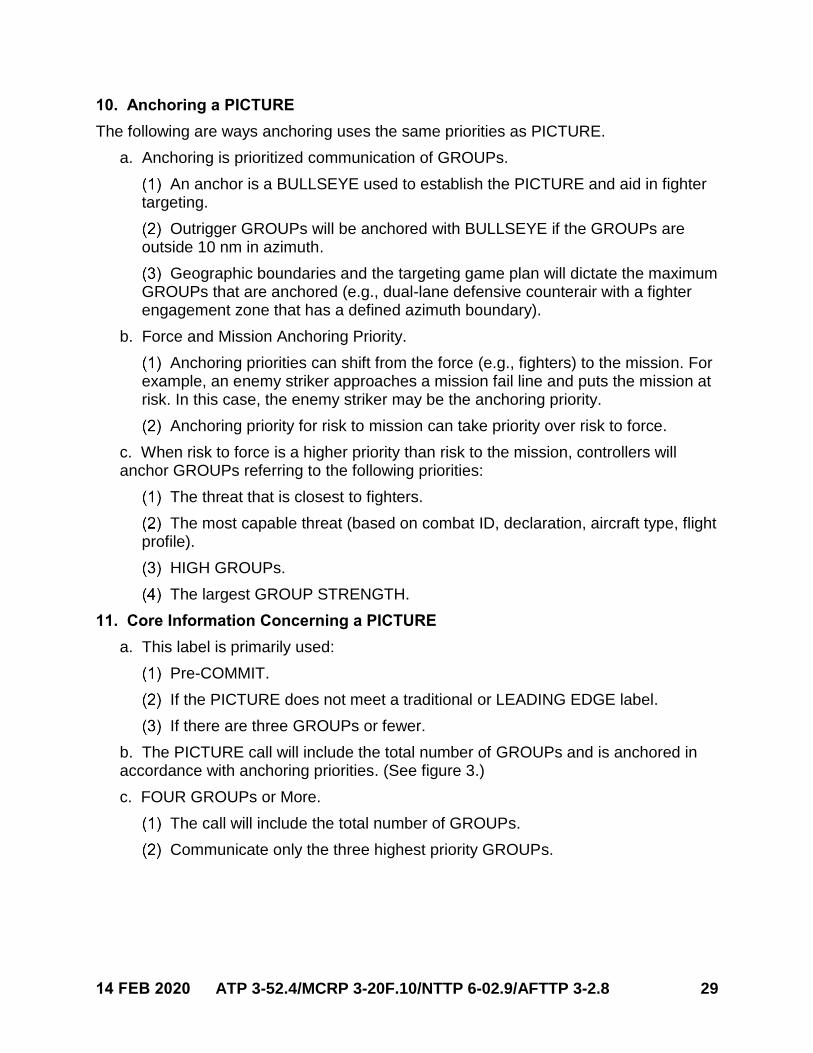
b. The PICTURE call will include the total number of GROUPs and is anchored inaccordance with anchoring priorities. (See figure 3.)
c. FOUR GROUPs or More.
The call will include the total number of GROUPs.
Communicate only the three highest priority GROUPs.
30 ATP 3-52.4/MCRP 3-20F.10/NTTP 6-02.9/AFTTP 3-2.8 14 FEB 2020
FOUR GROUPs or More Example
“DARKSTAR, TEN GROUPS. GROUP BULLSEYE 020/25, TWENTY-SEVEN THOUSAND, TRACK EAST, HOSTILE, HEAVY, THREE CONTACTS. GROUP BULLSEYE 270/25, FIFTEEN THOUSAND, TRACK WEST, HOSTILE. GROUP BULLSEYE 290/35, TEN THOUSAND, TRACK WEST, HOSTILE.”
12. Traditional Labels for a PICTURE
a. Controllers should use traditional labels and GROUP names with the followingcriteria:
COMMIT criteria has been met.
Threat formation is discernible and labeling a PICTURE will build SA and aid fighter targeting.
Figure 3. Pre-COMMIT Core Information
If a traditional label does not apply based on the threat presentation, controllers should use LEADING EDGE communication.
b. The standard labels used are: SINGLE GROUP, RANGE, AZIMUTH, VIC,CHAMPAGNE, WALL, LADDER, and BOX.
Note: FRIENDLY, NEUTRAL, STRANGERS, and nonparticipating GROUPs will not be included in the PICTURE or total number of GROUPs identified as part of the tactical picture. If FRIENDLY, NEUTRAL, STRANGERS, or nonparticipating GROUPs are a factor, they are addressed in a separate transmission.
14 FEB 2020 ATP 3-52.4/MCRP 3-20F.10/NTTP 6-02.9/AFTTP 3-2.8 31
13. Amplifying a Traditional Label for a PICTURE
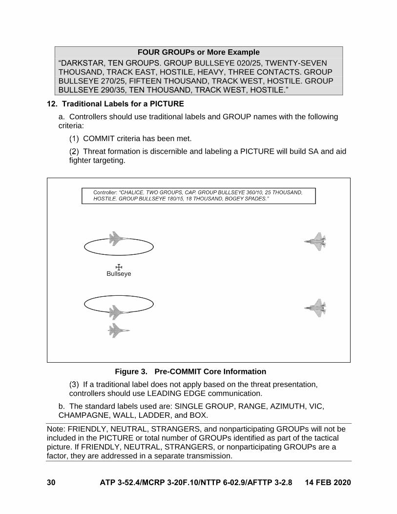
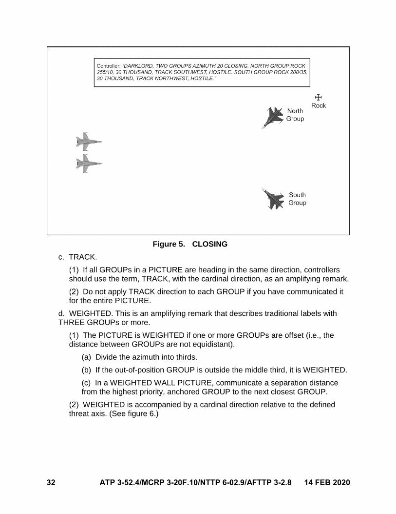
a. Amplifying remarks follow the dimensions of the traditional PICTURE.OPENING/CLOSING, TRACK, WEIGHTED, and ECHELON are the most commonamplifying remarks.
b. OPENING or CLOSING.
OPENING or CLOSING can be applied when the distance between GROUPs is increasing or decreasing and may impact the fighter intercept.
OPENING or CLOSING is placed following the PICTURE label and dimensions but in front of other amplifying remarks, such as ECHELON and TRACK. (See figures 4 and 5.)
Figure 4. OPENING
32 ATP 3-52.4/MCRP 3-20F.10/NTTP 6-02.9/AFTTP 3-2.8 14 FEB 2020
Figure 5. CLOSING
c. TRACK.
If all GROUPs in a PICTURE are heading in the same direction, controllersshould use the term, TRACK, with the cardinal direction, as an amplifying remark.
Do not apply TRACK direction to each GROUP if you have communicated itfor the entire PICTURE.
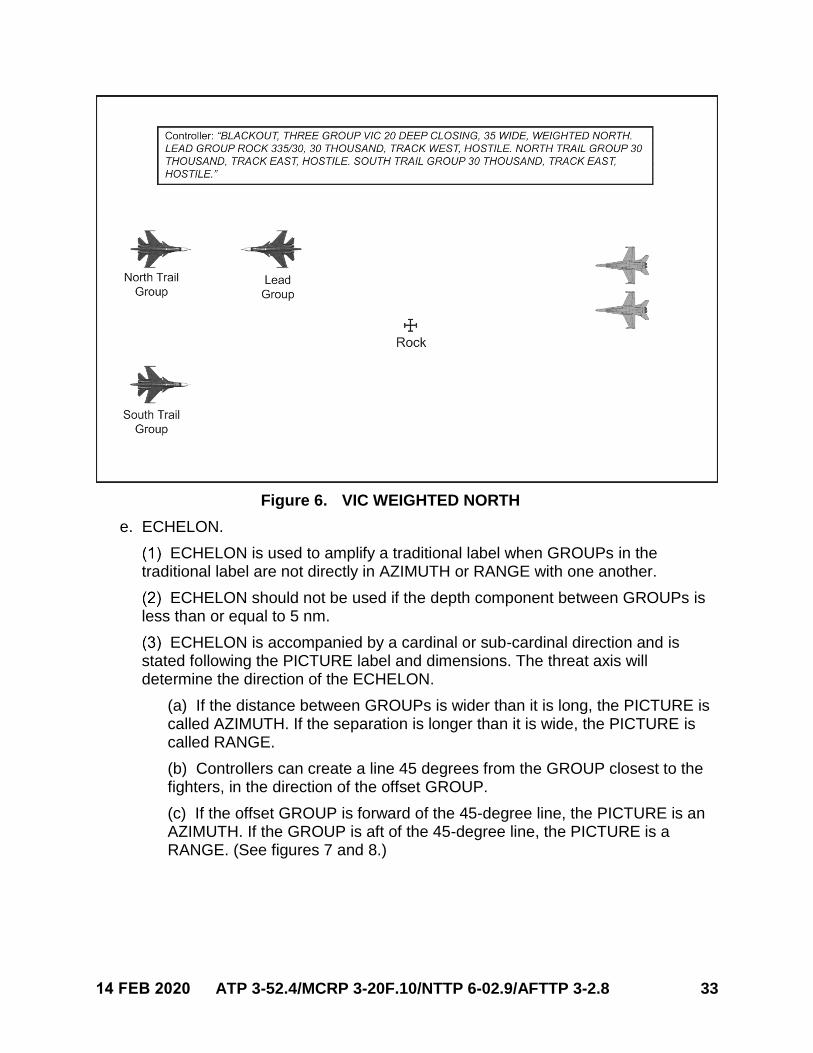
d. WEIGHTED. This is an amplifying remark that describes traditional labels withTHREE GROUPs or more.
The PICTURE is WEIGHTED if one or more GROUPs are offset (i.e., the distance between GROUPs are not equidistant).
(a) Divide the azimuth into thirds.
(b) If the out-of-position GROUP is outside the middle third, it is WEIGHTED.
(c) In a WEIGHTED WALL PICTURE, communicate a separation distancefrom the highest priority, anchored GROUP to the next closest GROUP.
WEIGHTED is accompanied by a cardinal direction relative to the defined threat axis. (See figure 6.)
14 FEB 2020 ATP 3-52.4/MCRP 3-20F.10/NTTP 6-02.9/AFTTP 3-2.8 33
Figure 6. VIC WEIGHTED NORTH
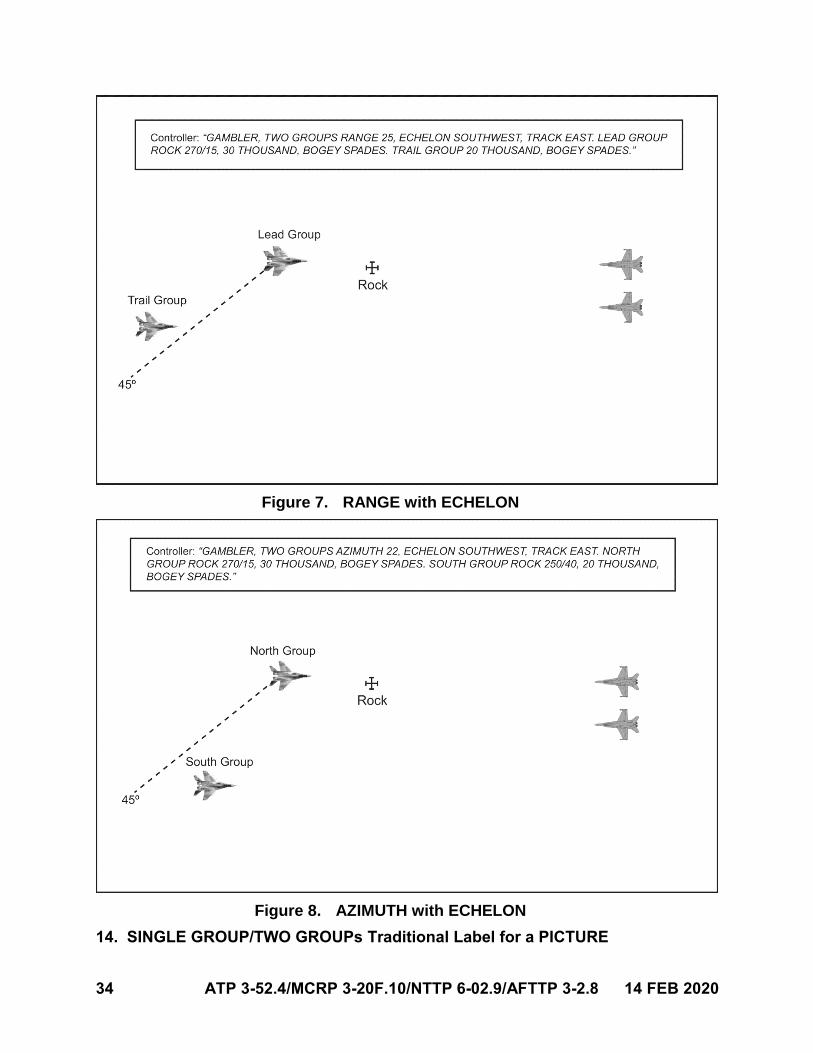
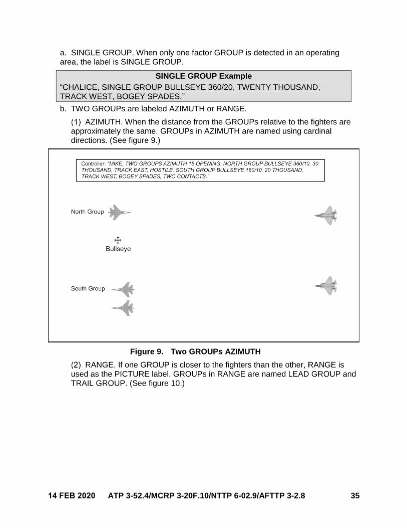
e. ECHELON.
ECHELON is used to amplify a traditional label when GROUPs in the traditional label are not directly in AZIMUTH or RANGE with one another.
ECHELON should not be used if the depth component between GROUPs is less than or equal to 5 nm.
ECHELON is accompanied by a cardinal or sub-cardinal direction and is stated following the PICTURE label and dimensions. The threat axis will determine the direction of the ECHELON.
(a) If the distance between GROUPs is wider than it is long, the PICTURE iscalled AZIMUTH. If the separation is longer than it is wide, the PICTURE iscalled RANGE.
(b) Controllers can create a line 45 degrees from the GROUP closest to thefighters, in the direction of the offset GROUP.
(c) If the offset GROUP is forward of the 45-degree line, the PICTURE is anAZIMUTH. If the GROUP is aft of the 45-degree line, the PICTURE is aRANGE. (See figures 7 and 8.)
34 ATP 3-52.4/MCRP 3-20F.10/NTTP 6-02.9/AFTTP 3-2.8 14 FEB 2020
Figure 7. RANGE with ECHELON
Figure 8. AZIMUTH with ECHELON
14. SINGLE GROUP/TWO GROUPs Traditional Label for a PICTURE
14 FEB 2020 ATP 3-52.4/MCRP 3-20F.10/NTTP 6-02.9/AFTTP 3-2.8 35
a. SINGLE GROUP. When only one factor GROUP is detected in an operatingarea, the label is SINGLE GROUP.
SINGLE GROUP Example
“CHALICE, SINGLE GROUP BULLSEYE 360/20, TWENTY THOUSAND, TRACK WEST, BOGEY SPADES.”
b. TWO GROUPs are labeled AZIMUTH or RANGE.
AZIMUTH. When the distance from the GROUPs relative to the fighters are approximately the same. GROUPs in AZIMUTH are named using cardinal directions. (See figure 9.)
Figure 9. Two GROUPs AZIMUTH
RANGE. If one GROUP is closer to the fighters than the other, RANGE is used as the PICTURE label. GROUPs in RANGE are named LEAD GROUP and TRAIL GROUP. (See figure 10.)
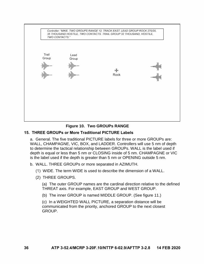
36 ATP 3-52.4/MCRP 3-20F.10/NTTP 6-02.9/AFTTP 3-2.8 14 FEB 2020
Figure 10. Two GROUPs RANGE
15. THREE GROUPs or More Traditional PICTURE Labels
a. General. The five traditional PICTURE labels for three or more GROUPs are:WALL, CHAMPAGNE, VIC, BOX, and LADDER. Controllers will use 5 nm of depthto determine the tactical relationship between GROUPs. WALL is the label used ifdepth is equal or less than 5 nm or CLOSING inside of 5 nm. CHAMPAGNE or VICis the label used if the depth is greater than 5 nm or OPENING outside 5 nm.
b. WALL. THREE GROUPs or more separated in AZIMUTH.
WIDE. The term WIDE is used to describe the dimension of a WALL.
THREE GROUPS.
(a) The outer GROUP names are the cardinal direction relative to the definedTHREAT axis. For example, EAST GROUP and WEST GROUP.
(b) The inner GROUP is named MIDDLE GROUP. (See figure 11.)
(c) In a WEIGHTED WALL PICTURE, a separation distance will becommunicated from the priority, anchored GROUP to the next closestGROUP.
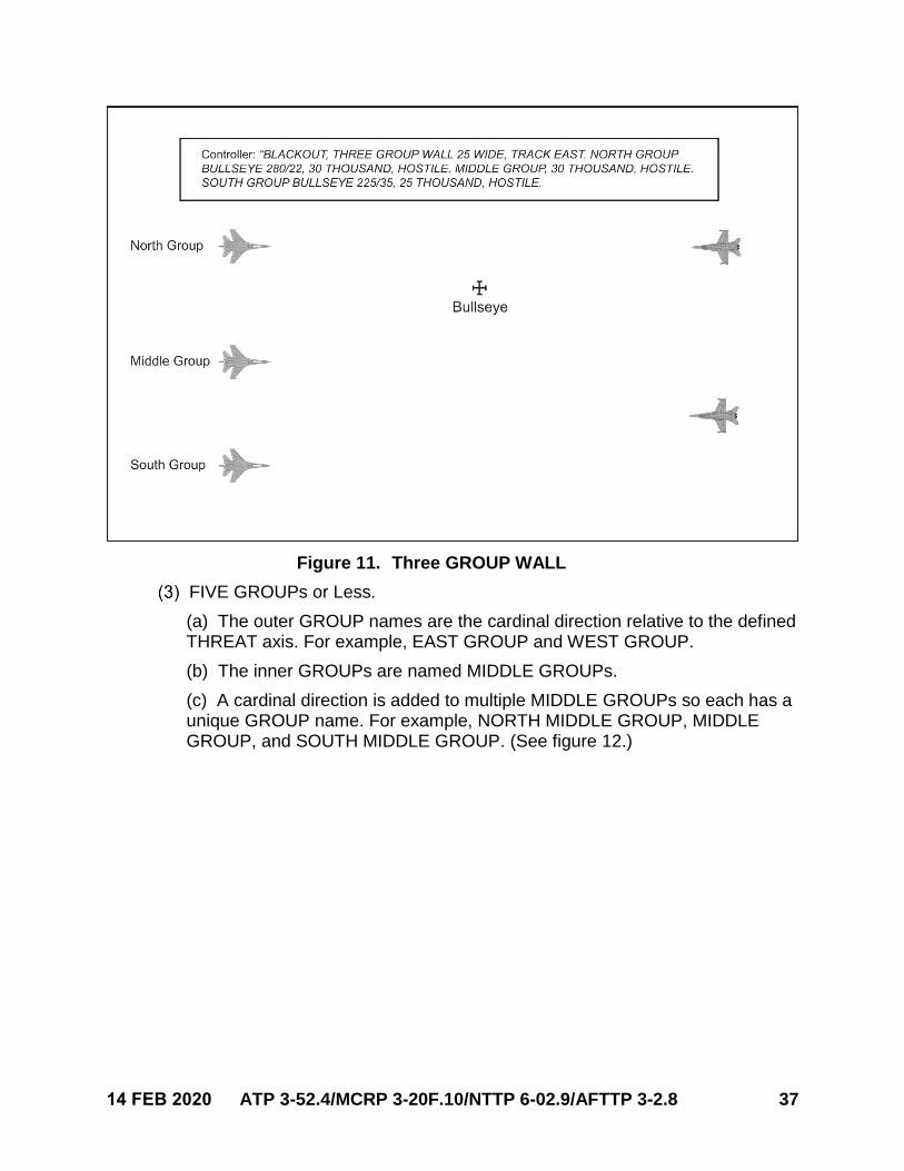
14 FEB 2020 ATP 3-52.4/MCRP 3-20F.10/NTTP 6-02.9/AFTTP 3-2.8 37
Figure 11. Three GROUP WALL
FIVE GROUPs or Less.
(a) The outer GROUP names are the cardinal direction relative to the definedTHREAT axis. For example, EAST GROUP and WEST GROUP.
(b) The inner GROUPs are named MIDDLE GROUPs.
(c) A cardinal direction is added to multiple MIDDLE GROUPs so each has aunique GROUP name. For example, NORTH MIDDLE GROUP, MIDDLEGROUP, and SOUTH MIDDLE GROUP. (See figure 12.)
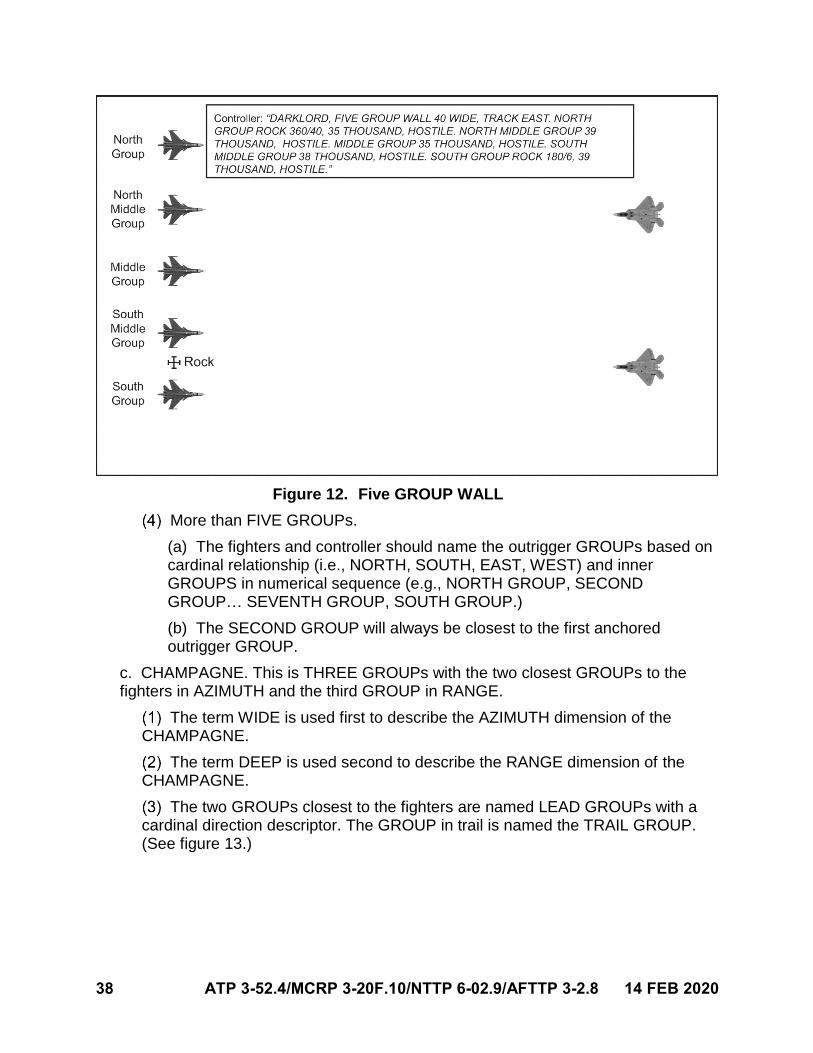
38 ATP 3-52.4/MCRP 3-20F.10/NTTP 6-02.9/AFTTP 3-2.8 14 FEB 2020
Figure 12. Five GROUP WALL
More than FIVE GROUPs.
(a) The fighters and controller should name the outrigger GROUPs based oncardinal relationship (i.e., NORTH, SOUTH, EAST, WEST) and innerGROUPS in numerical sequence (e.g., NORTH GROUP, SECONDGROUP… SEVENTH GROUP, SOUTH GROUP.)
(b) The SECOND GROUP will always be closest to the first anchoredoutrigger GROUP.
c. CHAMPAGNE. This is THREE GROUPs with the two closest GROUPs to thefighters in AZIMUTH and the third GROUP in RANGE.
The term WIDE is used first to describe the AZIMUTH dimension of the CHAMPAGNE.
The term DEEP is used second to describe the RANGE dimension of the CHAMPAGNE.
The two GROUPs closest to the fighters are named LEAD GROUPs with a cardinal direction descriptor. The GROUP in trail is named the TRAIL GROUP. (See figure 13.)
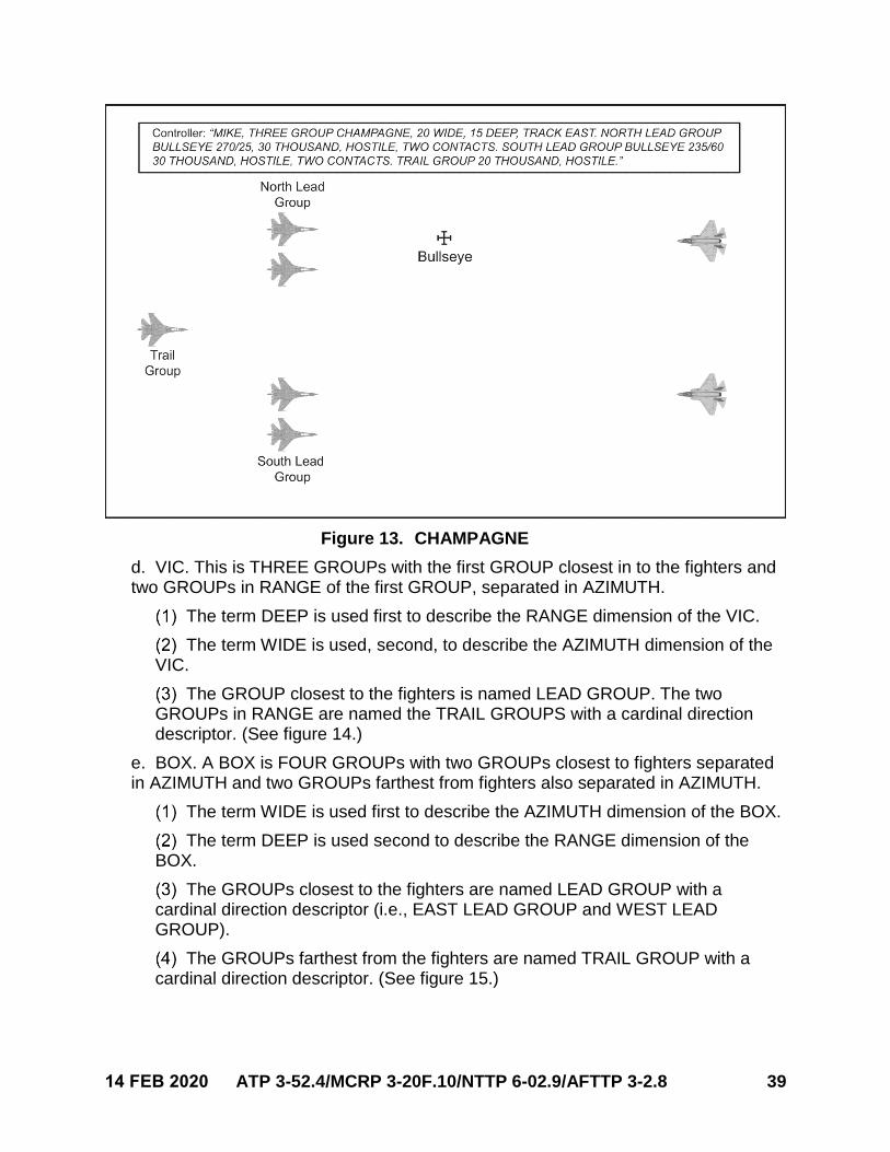
14 FEB 2020 ATP 3-52.4/MCRP 3-20F.10/NTTP 6-02.9/AFTTP 3-2.8 39
Figure 13. CHAMPAGNE
d. VIC. This is THREE GROUPs with the first GROUP closest in to the fighters andtwo GROUPs in RANGE of the first GROUP, separated in AZIMUTH.
The term DEEP is used first to describe the RANGE dimension of the VIC.
The term WIDE is used, second, to describe the AZIMUTH dimension of the VIC.
The GROUP closest to the fighters is named LEAD GROUP. The two GROUPs in RANGE are named the TRAIL GROUPS with a cardinal direction descriptor. (See figure 14.)
e. BOX. A BOX is FOUR GROUPs with two GROUPs closest to fighters separatedin AZIMUTH and two GROUPs farthest from fighters also separated in AZIMUTH.
The term WIDE is used first to describe the AZIMUTH dimension of the BOX.
The term DEEP is used second to describe the RANGE dimension of the BOX.
The GROUPs closest to the fighters are named LEAD GROUP with a cardinal direction descriptor (i.e., EAST LEAD GROUP and WEST LEAD GROUP).
The GROUPs farthest from the fighters are named TRAIL GROUP with a cardinal direction descriptor. (See figure 15.)
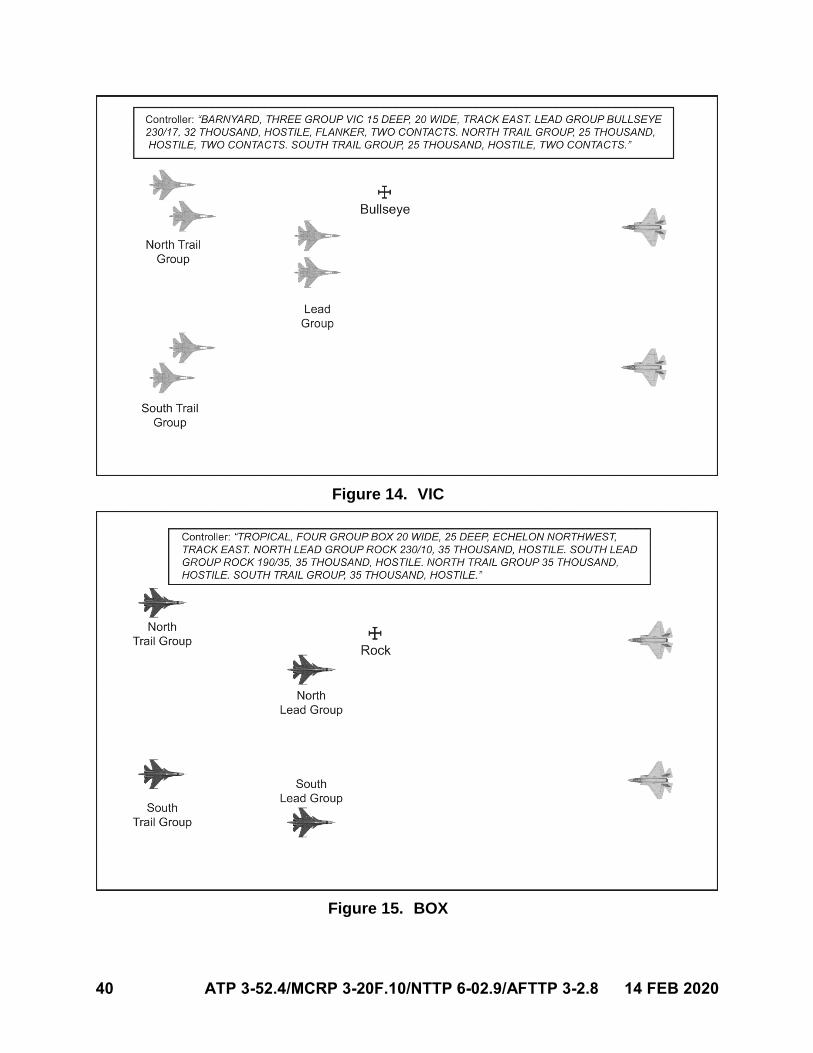
40 ATP 3-52.4/MCRP 3-20F.10/NTTP 6-02.9/AFTTP 3-2.8 14 FEB 2020
Figure 14. VIC
Figure 15. BOX
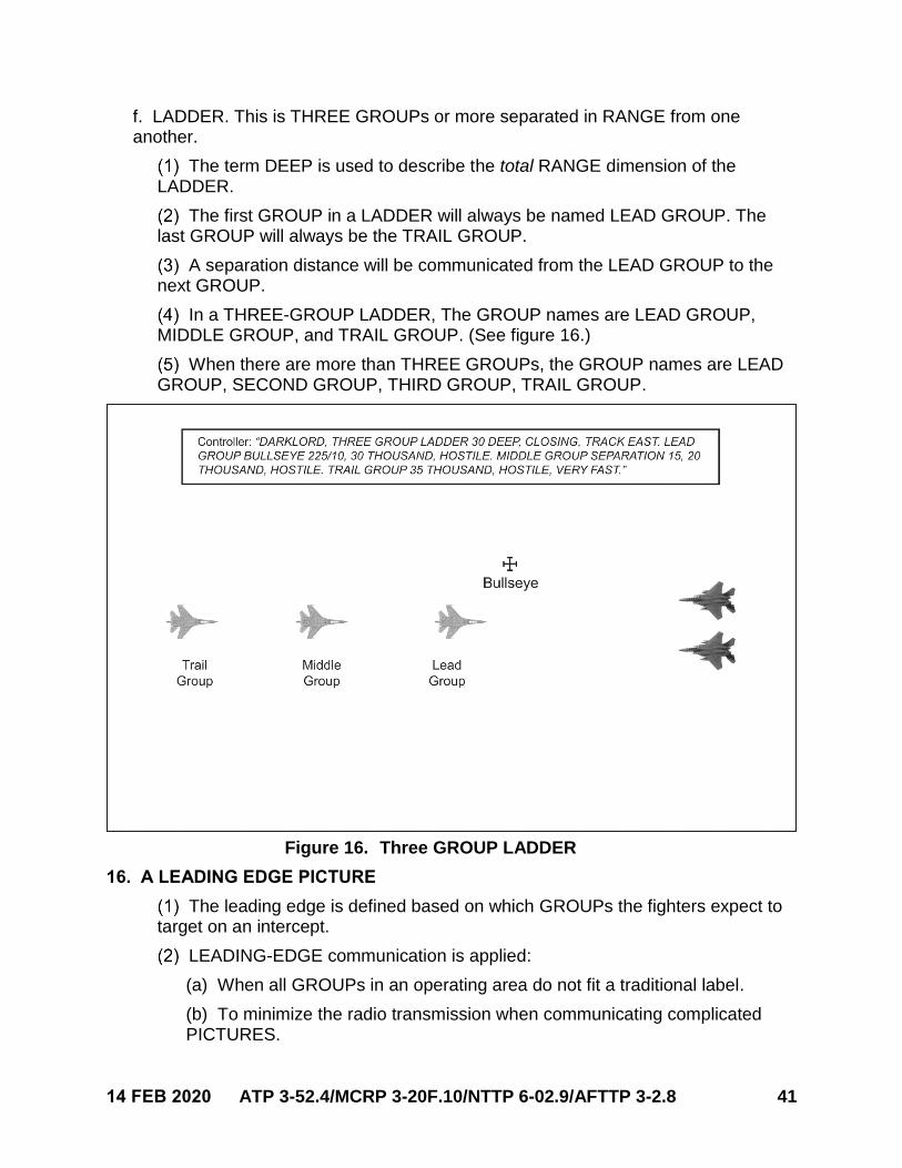
14 FEB 2020 ATP 3-52.4/MCRP 3-20F.10/NTTP 6-02.9/AFTTP 3-2.8 41
f. LADDER. This is THREE GROUPs or more separated in RANGE from oneanother.
The term DEEP is used to describe the total RANGE dimension of the LADDER.
The first GROUP in a LADDER will always be named LEAD GROUP. The last GROUP will always be the TRAIL GROUP.
A separation distance will be communicated from the LEAD GROUP to the next GROUP.
In a THREE-GROUP LADDER, The GROUP names are LEAD GROUP, MIDDLE GROUP, and TRAIL GROUP. (See figure 16.)
When there are more than THREE GROUPs, the GROUP names are LEAD GROUP, SECOND GROUP, THIRD GROUP, TRAIL GROUP.
Figure 16. Three GROUP LADDER
16. A LEADING EDGE PICTURE
The leading edge is defined based on which GROUPs the fighters expect to target on an intercept.
LEADING-EDGE communication is applied:
(a) When all GROUPs in an operating area do not fit a traditional label.
(b) To minimize the radio transmission when communicating complicatedPICTURES.
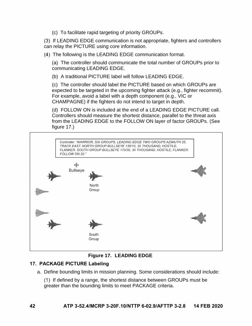
42 ATP 3-52.4/MCRP 3-20F.10/NTTP 6-02.9/AFTTP 3-2.8 14 FEB 2020
(c) To facilitate rapid targeting of priority GROUPs.
If LEADING EDGE communication is not appropriate, fighters and controllers can relay the PICTURE using core information.
The following is the LEADING EDGE communication format.
(a) The controller should communicate the total number of GROUPs prior tocommunicating LEADING EDGE.
(b) A traditional PICTURE label will follow LEADING EDGE.
(c) The controller should label the PICTURE based on which GROUPs areexpected to be targeted in the upcoming fighter attack (e.g., fighter recommit).For example, avoid a label with a depth component (e.g., VIC orCHAMPAGNE) if the fighters do not intend to target in depth.
(d) FOLLOW ON is included at the end of a LEADING EDGE PICTURE call.Controllers should measure the shortest distance, parallel to the threat axisfrom the LEADING EDGE to the FOLLOW ON layer of factor GROUPs. (Seefigure 17.)
Figure 17. LEADING EDGE
17. PACKAGE PICTURE Labeling
a. Define bounding limits in mission planning. Some considerations should include:
If defined by a range, the shortest distance between GROUPs must be greater than the bounding limits to meet PACKAGE criteria.
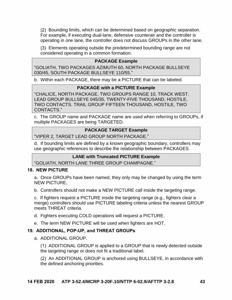
14 FEB 2020 ATP 3-52.4/MCRP 3-20F.10/NTTP 6-02.9/AFTTP 3-2.8 43
Bounding limits, which can be determined based on geographic separation. For example, if executing dual-lane, defensive counterair and the controller is operating in one lane, the controller does not discuss GROUPs in the other lane.
Elements operating outside the predetermined bounding range are not considered operating in a common formation.
PACKAGE Example
“GOLIATH, TWO PACKAGES AZIMUTH 60, NORTH PACKAGE BULLSEYE 030/45, SOUTH PACKAGE BULLSEYE 110/55.”
b. Within each PACKAGE, there may be a PICTURE that can be labeled.
PACKAGE with a PICTURE Example
“CHALICE, NORTH PACKAGE, TWO GROUPS RANGE 10, TRACK WEST. LEAD GROUP BULLSEYE 045/35, TWENTY-FIVE THOUSAND, HOSTILE, TWO CONTACTS. TRAIL GROUP FIFTEEN THOUSAND, HOSTILE, TWO CONTACTS.”
c. The GROUP name and PACKAGE name are used when referring to GROUPs, ifmultiple PACKAGES are being TARGETED.
PACKAGE TARGET Example
“VIPER 2, TARGET LEAD GROUP NORTH PACKAGE.”
d. If bounding limits are defined by a known geographic boundary, controllers mayuse geographic references to describe the relationship between PACKAGES.
LANE with Truncated PICTURE Example
“GOLIATH, NORTH LANE THREE GROUP CHAMPAGNE.”
18. NEW PICTURE
a. Once GROUPs have been named, they only may be changed by using the termNEW PICTURE.
b. Controllers should not make a NEW PICTURE call inside the targeting range.
c. If fighters request a PICTURE inside the targeting range (e.g., fighters clear amerge) controllers should use PICTURE labeling criteria unless the nearest GROUPmeets THREAT criteria.
d. Fighters executing COLD operations will request a PICTURE.
e. The term NEW PICTURE will be used when fighters are HOT.
19. ADDITIONAL, POP-UP, and THREAT GROUPs
a. ADDITIONAL GROUP.
ADDITIONAL GROUP is applied to a GROUP that is newly detected outside the targeting range or does not fit a traditional label.
An ADDITIONAL GROUP is anchored using BULLSEYE, in accordance with the defined anchoring priorities.
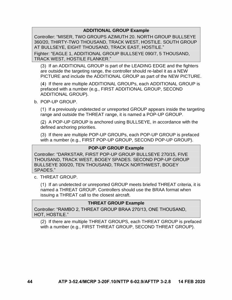
44 ATP 3-52.4/MCRP 3-20F.10/NTTP 6-02.9/AFTTP 3-2.8 14 FEB 2020
ADDITIONAL GROUP Example
Controller: “MISER, TWO GROUPS AZIMUTH 20. NORTH GROUP BULLSEYE 360/20, THIRTY-TWO THOUSAND, TRACK WEST, HOSTILE. SOUTH GROUP AT BULLSEYE, EIGHT THOUSAND, TRACK EAST, HOSTILE.”
Fighter: “EAGLE 1, ADDITIONAL GROUP BULLSEYE 090/7, 5 THOUSAND, TRACK WEST, HOSTILE FLANKER.”
If an ADDITIONAL GROUP is part of the LEADING EDGE and the fighters are outside the targeting range, the controller should re-label it as a NEW PICTURE and include the ADDITIONAL GROUP as part of the NEW PICTURE.
If there are multiple ADDITIONAL GROUPs, each ADDITIONAL GROUP is prefaced with a number (e.g., FIRST ADDITIONAL GROUP, SECOND ADDITIONAL GROUP).
b. POP-UP GROUP.
If a previously undetected or unreported GROUP appears inside the targeting range and outside the THREAT range, it is named a POP-UP GROUP.
A POP-UP GROUP is anchored using BULLSEYE, in accordance with the defined anchoring priorities.
If there are multiple POP-UP GROUPs, each POP-UP GROUP is prefaced with a number (e.g., FIRST POP-UP GROUP, SECOND POP-UP GROUP).
POP-UP GROUP Example
Controller: “DARKSTAR, FIRST POP-UP GROUP BULLSEYE 270/15, FIVE THOUSAND, TRACK WEST, BOGEY SPADES. SECOND POP-UP GROUP BULLSEYE 300/20, TEN THOUSAND, TRACK NORTHWEST, BOGEY SPADES.”
c. THREAT GROUP.
If an undetected or unreported GROUP meets briefed THREAT criteria, it is named a THREAT GROUP. Controllers should use the BRAA format when issuing a THREAT call to the closest aircraft.
THREAT GROUP Example
Controller: “RAMBO 2, THREAT GROUP BRAA 270/13, ONE THOUSAND, HOT, HOSTILE.”
If there are multiple THREAT GROUPS, each THREAT GROUP is prefaced with a number (e.g., FIRST THREAT GROUP, SECOND THREAT GROUP).
14 FEB 2020 ATP 3-52.4/MCRP 3-20F.10/NTTP 6-02.9/AFTTP 3-2.8 45
Chapter V AIR-TO-AIR INTERCEPT COMMUNICATION
1. Overview
This chapter establishes a communication format for A/A employment and air intercept control. It governs communication fundamentals, format, and integration between fighters and controllers, independent of MDS or T/M/S. This chapter is the baseline for all A/A communication in training and combat. Service-specific differences are annotated. Refer to the following weapons schools for Service-specific tactics and employment considerations:
a. United States Army Aviation Center of Excellence (USAACE), Fort Rucker,Alabama.
b. Marine Aviation Weapons and Tactics Squadron One (MAWTS-1), Marine CorpsAir Station, Yuma, Arizona.
c. Naval Aviation Warfighting Development Center (NAWDC) N7 (Topgun), FallonNaval Air Station, Nevada.
d. United States Air Force Weapons School (USAFWS), Nellis Air Force Base,Nevada.
Note: For the purpose of this publication, controller is a general term used to define the individual providing tactical control of an intercept, or mission. The term fighter is the example used throughout this chapter but this information applies to any aircraft capable of employing A/A ordnance. Controller and fighter are used independent of platform or Service.
2. Communication Cadence by Intercept Phase
a. The A/A communication cadence establishes the flow of information duringdifferent phases of a mission. It ensures fighters receive priority informationtransmitted by the controller.
Communication priorities shift between controllers and fighters during different phases of an intercept.
Priorities shift based on what asset has the most SA to communicate time-sensitive information.
b. Table 7 outlines the A/A intercept phases and the communication priorities.
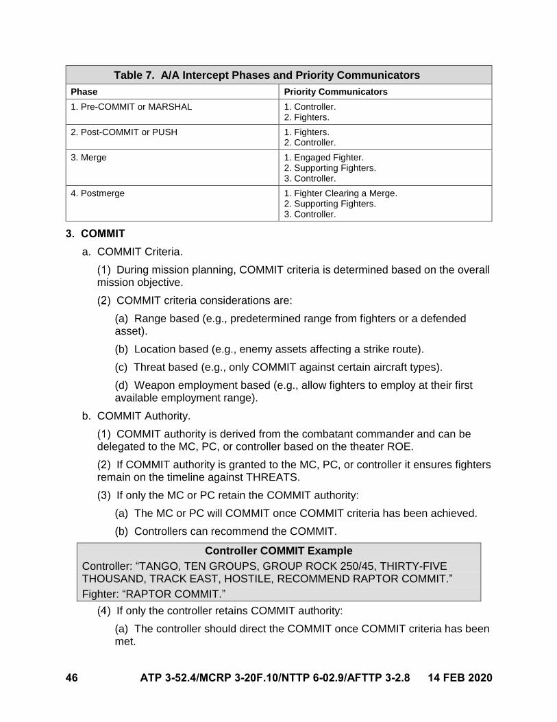
46 ATP 3-52.4/MCRP 3-20F.10/NTTP 6-02.9/AFTTP 3-2.8 14 FEB 2020
Table 7. A/A Intercept Phases and Priority Communicators
Phase Priority Communicators
1. Pre-COMMIT or MARSHAL 1. Controller.2. Fighters.
2. Post-COMMIT or PUSH 1. Fighters.2. Controller.
3. Merge 1. Engaged Fighter.2. Supporting Fighters.3. Controller.
4. Postmerge 1. Fighter Clearing a Merge.2. Supporting Fighters.3. Controller.
3. COMMIT
a. COMMIT Criteria.
During mission planning, COMMIT criteria is determined based on the overall mission objective.
COMMIT criteria considerations are:
(a) Range based (e.g., predetermined range from fighters or a defendedasset).
(b) Location based (e.g., enemy assets affecting a strike route).
(c) Threat based (e.g., only COMMIT against certain aircraft types).
(d) Weapon employment based (e.g., allow fighters to employ at their firstavailable employment range).
b. COMMIT Authority.
COMMIT authority is derived from the combatant commander and can be delegated to the MC, PC, or controller based on the theater ROE.
If COMMIT authority is granted to the MC, PC, or controller it ensures fighters remain on the timeline against THREATS.
If only the MC or PC retain the COMMIT authority:
(a) The MC or PC will COMMIT once COMMIT criteria has been achieved.
(b) Controllers can recommend the COMMIT.
Controller COMMIT Example
Controller: “TANGO, TEN GROUPS, GROUP ROCK 250/45, THIRTY-FIVE THOUSAND, TRACK EAST, HOSTILE, RECOMMEND RAPTOR COMMIT.”
Fighter: “RAPTOR COMMIT.”
If only the controller retains COMMIT authority:
(a) The controller should direct the COMMIT once COMMIT criteria has beenmet.
14 FEB 2020 ATP 3-52.4/MCRP 3-20F.10/NTTP 6-02.9/AFTTP 3-2.8 47
(b) The MC or PC may only recommend COMMIT.
Recommend COMMIT Example
Fighter: “RAPTOR 1, RECOMMEND COMMIT.”
Controller: “TANGO, TEN GROUPS, GROUP ROCK 250/45, THIRTY-FIVE THOUSAND, TRACK EAST, HOSTILE, RAPTOR COMMIT.”
Fighter: “RAPTOR 1.”
Two-way communication between the fighters and controller is required when a COMMIT is recommended or directed.
If a COMMIT is directed by the fighter, the controller will transition from pre-COMMIT communication standards to tactical control and traditional label or LEADING EDGE PICTURE communication.
Fighter COMMIT Example
Fighter: “RAPTOR COMMIT.”
Controller: “TANGO, TEN GROUPS, LEADING EDGE TWO GROUPS AZIMUTH 40, TRACK EAST. NORTH GROUP ROCK 300/15, THIRTY-FIVE THOUSAND, HOSTILE. SOUTH GROUP ROCK 230/20, THIRTY-FIVE THOUSAND HOSTILE. FOLLOW-ON GROUP 25.”
4. Tactical (TAC) Range Call
a. Fighters should prebrief the “TAC range” call with controllers.
b. A 45-nm separation from the closest fighter to the closest GROUP is a default.
c. The first to recognize the appropriate separation will make the “TAC range” callusing the closest fighter call sign and the closest GROUP name.
TAC Range Example
“SHOWTIME 11, NORTH GROUP 45 MILES.”
5. Electronic Attack
a. STROBE. Controllers will respond to STROBE calls with range, altitude, aspect,declaration, and GROUP name (if applicable) to the closest GROUP along that lineof bearing.
STROBE Example
Fighter: “RAMBO 1, STROBE 3-6-0” or “RAMBO 1, STROBE LEAD GROUP.”
Controller: “RAMBO 1, STROBE RANGE 37, TWENTY-FIVE THOUSAND, HOT, HOSTILE, LEAD GROUP.”
b. MUSIC.
MUSIC is an informative call that fighters are experiencing radar electronic deceptive jamming from a GROUP.
Controllers will respond to MUSIC calls by anchoring the GROUP off BULLSEYE and providing the altitude, track direction, declaration, and fill-ins.
MUSIC Example
48 ATP 3-52.4/MCRP 3-20F.10/NTTP 6-02.9/AFTTP 3-2.8 14 FEB 2020
Fighter: “HEAT 1, MUSIC EAST GROUP.”
Controller: “BARNYARD, EAST GROUP, BULLSEYE 210/15, TWENTY-FIVE THOUSAND, TRACK EAST, HOSTILE, 2 CONTACTS LINE ABREAST THREE.”
Note: If controllers cannot correlate STROBE or MUSIC to a GROUP, they should respond with CLEAN. This indicates the contact may be below the controller sensor coverage or may be a ground-based jammer.
c. METALLICA.
This is an informative call to communicate electronic attack is preventing fighter employment on a specific GROUP.
Controllers are not required to respond to METALLICA.
METALLICA does not alleviate fighter targeting responsibility for a GROUP.
METALLICA Example
Fighter: “PYTHON 2, METALLICA LEAD GROUP.”
6. CLEAN
a. If a fighter calls CLEAN on their targeting responsibility, controllers will provide afull positional update or respond with CLEAN, FADED, or VANISHED.
CLEAN Example
“MIKE, SHOWTIME 11 CLEAN NORTH GROUP.”
“MIKE, NORTH GROUP BULLSEYE 290/35, 3EIGHT THOUSAND, TRACK EAST, HOSTILE.”
b. If fighters are CLEAN to a GROUP and desire a GROUP location relative toownship, they should request a BRAA/BOGEY DOPE to the GROUP.
BRAA Request Example
“MIKE, SHOWTIME 11 BRAA NORTH GROUP.”
“SHOWTIME 11, NORTH GROUP BRAA 210/28, THIRTY EIGHT THOUSAND, HOT, HOSTILE.”
BOGEY DOPE Request Example
“MIKE, SHOWTIME 11 BOGEY DOPE NORTH GROUP.”
“SHOWTIME 11, NORTH GROUP BRAA 210/28, THIRTY EIGHT THOUSAND, HOT, HOSTILE.”
7. DECLARE
a. A DECLARE call is an interrogative call (i.e., request for information) made byeither the fighters or controller.
b. Use the following communication format.
Call sign of asset maintaining custody to the GROUP.
The requesting asset’s call sign.
14 FEB 2020 ATP 3-52.4/MCRP 3-20F.10/NTTP 6-02.9/AFTTP 3-2.8 49
“DECLARE BULLSEYE.”
Position of the group in the BULLSEYE format.
Altitude.
Track direction (only required to discriminate).
DECLARE Request Example 1
“DARKSTAR, VIPER 1, DECLARE BULLSEYE 230/12, 12 THOUSAND.”
c. When a declaration request is made after the tactical picture has been labeled,the GROUP name can be used instead of the BULLSEYE location.
DECLARE Request Example 2
“CHALICE, HORNET 1, DECLARE EAST GROUP.”
d. DECLARE Response.
Controllers will always respond to a DECLARE request with BULLSEYE,altitude, track direction, declaration, and fill-ins.
DECLARE responses may include: BOGEY, FRIENDLY, NEUTRAL,BANDIT, HOSTILE, FURBALL, UNABLE, or CLEAN (VANISHED can be used intraining).
DECLARE Response Example
“CHALICE, EAST GROUP BULLSEYE 273/27, 22 THOUSAND, TRACK EAST, BOGEY SPADES.”
8. HOSTILE Declaration During Shot Communication
a. If a fighter determines a GROUP HOSTILE, and engagement ROE has beenmet, the fighter may employ weapons against that GROUP.
b. Fighters should communicate GROUP BULLSEYE, altitude, and HOSTILE in theshot transmission so other fighters and the controller can correlate to each other.
c. Track direction is included only if it enhances SA.
Track Direction Example
“RAPTOR 1, FOX 3 LEAD GROUP BULLSEYE 125/27, 29 THOUSAND, TRACK NORTH, HOSTILE.”
d. Controllers can upgrade GROUPs declared BOGEY or BANDIT to HOSTILEwithout correlating to BULLSEYE if a correlated J12.6 and shot line are displayedwithin 3 nm of a surveillance track. A voice correlation with a J12.6 and shot line arenot mandatory for a controller declaration upgrade to HOSTILE.
Note: Not all controller platforms can correlate a J12.6 and shot line. Query the controlling platform during mission planning to evaluate this contract.
50 ATP 3-52.4/MCRP 3-20F.10/NTTP 6-02.9/AFTTP 3-2.8 14 FEB 2020
9. SHOOT
a. This is directive communication by fighters for missile employment against aspecific GROUP or CONTACT when fighters are targeting another GROUP. Thisdoes not imply BANZAI flow to the GROUP or CONTACT.
SHOOT Example
Fighter: “BOLT 4, SHOOT SOUTHERN SOUTH LEAD GROUP.”
b. Targeting responsibility is cancelled when the fighters communicate any of thefollowing: DROP (GROUP name), BLOW THROUGH, STIFF ARM, SPITTER, orexecutes an out.
10. GROUP Maneuvers
a. Controllers and fighters are responsible to communicate GROUP maneuvers.The three components to each maneuver are:
Recognizing the maneuver.
Communicating the relationship of the maneuver.
Updating GROUP names to aid in fighter targeting.
b. GROUPs maneuver into ARMS. ARMS maneuver into CONTACTs.
Once a maneuver is recognized, it is communicated using the term MANEUVER.
If a maneuver direction can be determined, the controller or fighter will update the maneuver using: own CALL SIGN, GROUP name, and type of maneuver (e.g., BEAM NORTH or DRAG EAST).
GROUP Maneuver Example 1
“DARKSTAR, LEAD GROUP BEAM NORTH.”
If a specific aspect is not applicable to all fighters, controllers and fighters should use the TRACK DIRECTION to describe the maneuver.
GROUP Maneuver Example 2
“DARKSTAR, LEAD GROUP TRACK NORTH.”
Note: Maneuvers can drive a NEW PICTURE if it is outside targeting range or during COLD operations.
c. AZIMUTH and RANGE Maneuvers.
The terms MANEUVER AZIMUTH or MANEUVER RANGE are used if a GROUP maneuvers outside GROUP criteria. (See figures 18–20.)
Communicate “MANEUVER RANGE AND AZIMUTH” if three or more CONTACTs maneuver in range and azimuth simultaneously while the CONTACT(S) remains FLANK/HOT.
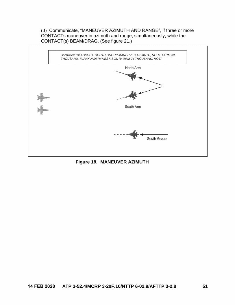
14 FEB 2020 ATP 3-52.4/MCRP 3-20F.10/NTTP 6-02.9/AFTTP 3-2.8 51
Communicate, “MANEUVER AZIMUTH AND RANGE”, if three or more CONTACTs maneuver in azimuth and range, simultaneously, while the CONTACT(s) BEAM/DRAG. (See figure 21.)
Figure 18. MANEUVER AZIMUTH
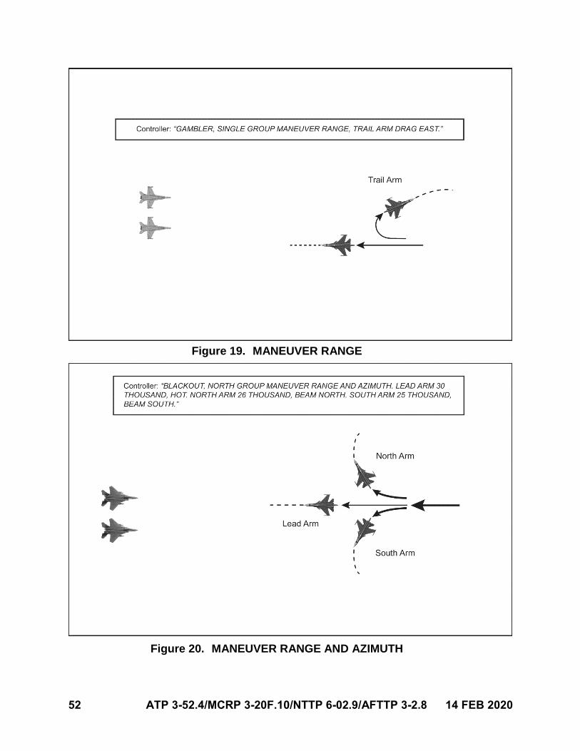
52 ATP 3-52.4/MCRP 3-20F.10/NTTP 6-02.9/AFTTP 3-2.8 14 FEB 2020
Figure 19. MANEUVER RANGE
Figure 20. MANEUVER RANGE AND AZIMUTH
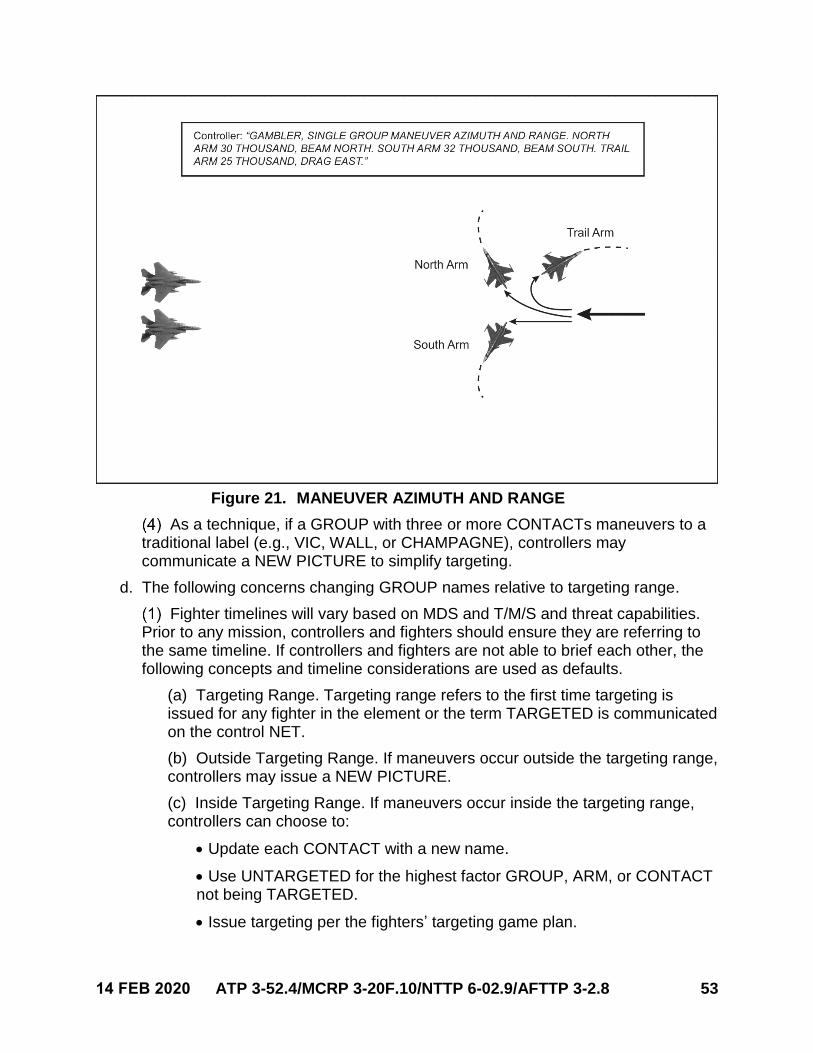
14 FEB 2020 ATP 3-52.4/MCRP 3-20F.10/NTTP 6-02.9/AFTTP 3-2.8 53
Figure 21. MANEUVER AZIMUTH AND RANGE
As a technique, if a GROUP with three or more CONTACTs maneuvers to a traditional label (e.g., VIC, WALL, or CHAMPAGNE), controllers may communicate a NEW PICTURE to simplify targeting.
d. The following concerns changing GROUP names relative to targeting range.
Fighter timelines will vary based on MDS and T/M/S and threat capabilities. Prior to any mission, controllers and fighters should ensure they are referring to the same timeline. If controllers and fighters are not able to brief each other, the following concepts and timeline considerations are used as defaults.
(a) Targeting Range. Targeting range refers to the first time targeting isissued for any fighter in the element or the term TARGETED is communicatedon the control NET.
(b) Outside Targeting Range. If maneuvers occur outside the targeting range,controllers may issue a NEW PICTURE.
(c) Inside Targeting Range. If maneuvers occur inside the targeting range,controllers can choose to:
Update each CONTACT with a new name.
Use UNTARGETED for the highest factor GROUP, ARM, or CONTACTnot being TARGETED.
Issue targeting per the fighters’ targeting game plan.
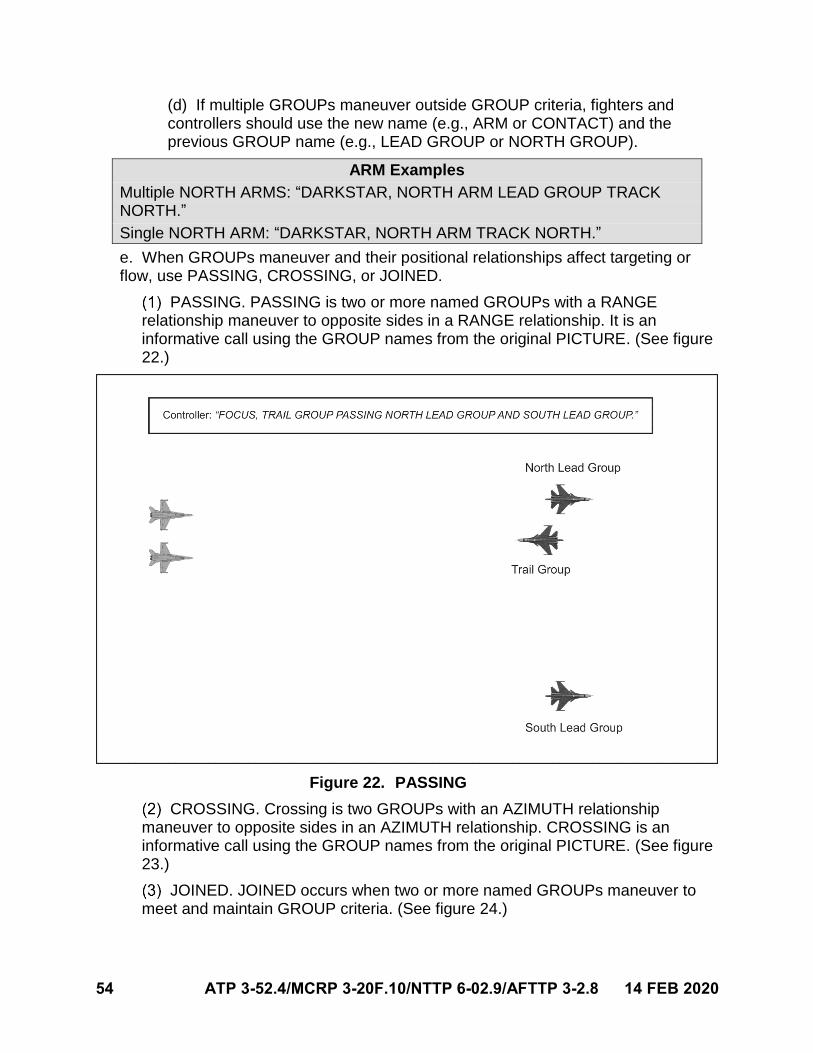
54 ATP 3-52.4/MCRP 3-20F.10/NTTP 6-02.9/AFTTP 3-2.8 14 FEB 2020
(d) If multiple GROUPs maneuver outside GROUP criteria, fighters andcontrollers should use the new name (e.g., ARM or CONTACT) and theprevious GROUP name (e.g., LEAD GROUP or NORTH GROUP).
ARM Examples
Multiple NORTH ARMS: “DARKSTAR, NORTH ARM LEAD GROUP TRACK NORTH.”
Single NORTH ARM: “DARKSTAR, NORTH ARM TRACK NORTH.”
e. When GROUPs maneuver and their positional relationships affect targeting orflow, use PASSING, CROSSING, or JOINED.
PASSING. PASSING is two or more named GROUPs with a RANGE relationship maneuver to opposite sides in a RANGE relationship. It is an informative call using the GROUP names from the original PICTURE. (See figure 22.)
Figure 22. PASSING
CROSSING. Crossing is two GROUPs with an AZIMUTH relationship maneuver to opposite sides in an AZIMUTH relationship. CROSSING is an informative call using the GROUP names from the original PICTURE. (See figure 23.)
JOINED. JOINED occurs when two or more named GROUPs maneuver to meet and maintain GROUP criteria. (See figure 24.)
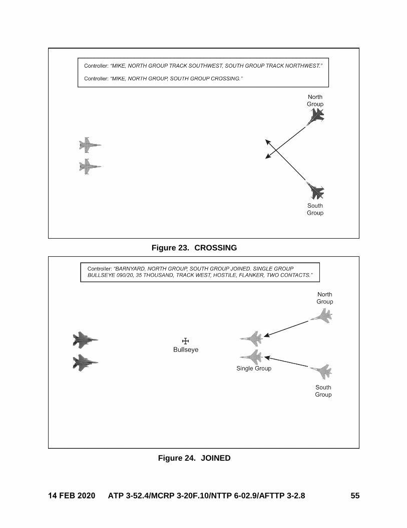
14 FEB 2020 ATP 3-52.4/MCRP 3-20F.10/NTTP 6-02.9/AFTTP 3-2.8 55
Figure 23. CROSSING
Figure 24. JOINED
56 ATP 3-52.4/MCRP 3-20F.10/NTTP 6-02.9/AFTTP 3-2.8 14 FEB 2020
11. MERGE Phase
a. Controllers should refer to fighters as MERGED when the resolution capabilitiesof the controller systems become limiting factors or when fighters are within 3–5 nmof a GROUP.
b. Controllers should talk to a MERGED fighter for:
Fighter requests.
THREAT calls.
TRESPASS calls.
STRENGTH disparity (e.g., comparative communication).
Update fighter flow direction to follow on GROUPs (if required).
c. Controllers should refer MERGE phase paragraph 11.b. if a fighter callsANCHORED (GROUP name) or STANDBY (GROUP name).
d. ANCHORED or STANDBY calls should include the BULLSEYE location, if theGROUP does not have a name.
ANCHORED Example
Fighter: “RAPTOR 1, STANDBY SOUTH GROUP” or “RAPTOR 1, ANCHORED BULLSEYE 170/50.”
e. SEPARATION.
SEPARATION is a request for distance (nm) between two GROUPs.
(a) It is used when a fighter is ANCHORED.
(b) SEPARATION request implies it is from the current ANCHORED GROUPto the requested GROUP, if not specified.
In the SEPARATION response, controllers should use their call sign followedby the follow-on GROUP’s SEPARATION, altitude, and fill-ins.
Controllers may use RANGE SEPARATION or AZIMUTH SEPARATION, if the tactical relationship between GROUPs changed and the controller did not have the ability to make a NEW PICTURE call.
SEPARATION Example
Fighter: “RAPTOR 1, ANCHORED SOUTH GROUP.”
Controller: “RAPTOR 1, CHALICE, SOUTH GROUP TWO CONTACTS.”
Fighter: “CHALICE, RAPTOR 1, SEPARATION NORTH GROUP.”
Controller: “RAPTOR 1, NORTH GROUP RANGE SEPARATION 10 OPENING, TWENTY-FIVE THOUSAND, DRAG WEST, HOSTILE.”
14 FEB 2020 ATP 3-52.4/MCRP 3-20F.10/NTTP 6-02.9/AFTTP 3-2.8 57
12. COLD Operations
a. Fighters should communicate COLD operations with either “FLOW COLD” orFLOW with a COLD heading.
FLOW Example
“SHOWTIME, FLOW COLD.” or “SHOWTIME, FLOW 0-9-0.”
b. Communication priorities are as follows:
SPIKES or THREATS within a stern weapon engagement zone.
FADED or POP-UP GROUPs inside the LEADING EDGE.
DELOUSE or directive targeting.
PICTURE.
Fighter targeting game plan.
13. SPIKE
a. Fighters call SPIKED with a bearing or cardinal/sub-cardinal direction.
The controller should correlate the SPIKE ±30 degrees of the bearing to a detected GROUP.
Respond with the range, altitude, aspect, declaration, GROUP name (if applicable), and fill-ins.
SPIKED Example 1
Fighter: “EAGLE 1, SPIKED 2-7-0.”
Controller: “EAGLE 1, SPIKE RANGE 17, THIRTY THOUSAND, HOT, HOSTILE EAST GROUP, TWO CONTACTS.”
b. If a controller cannot correlate a GROUP along the aircraft’s spike bearing orcardinal direction, controllers will respond with CLEAN and the bearing of the SPIKE.
SPIKED Example 2
Fighter: “EAGLE 1, SPIKED 2-7-0.”
Controller: “EAGLE 1, WARRIOR CLEAN 2-7-0.”
14. THREAT Call
a. If a fighter will pierce the THREAT range to an UNTARGETED GROUP, aTHREAT call is made using the GROUP name, bearing or cardinal/sub-cardinaldirection, range, altitude, and aspect, followed by declaration and fill-ins.
b. The THREAT call is completed no later than threat range.
c. THREAT criteria is defined during mission planning and relayed during the briefor check in with the controller.
Controllers should use 35 nm, independent of aspect, as a default THREAT criteria.
58 ATP 3-52.4/MCRP 3-20F.10/NTTP 6-02.9/AFTTP 3-2.8 14 FEB 2020
THREAT Example
Controller: “HEAT 31, ADDITIONAL GROUP THREAT BRAA 125/35, THIRTY-FIVE THOUSAND, HOT, HOSTILE.”
If the exact fighter location is not known, THREAT information may be provided using BULLSEYE.
(a) BULLSEYE will immediately follow the word THREAT.
(b) If a fighter receives a THREAT BULLSEYE call, the fighter shouldrespond with own call sign.
Note: When communicating with United States Army or United States Marine Corps rotary-wing aircraft and UASs, pass surface threat information in MGRS. Attempt to provide at least a six-digit grid.
THREAT with BULLSEYE Example
Controller: “COBRA 1, CHALICE, NORTH GROUP THREAT BULLSEYE 295/26, TWENTY THOUSAND, TRACK WEST, HOSTILE.”
When a THREAT is within 5 nm of FRIENDLY fighters, controllers may provide THREAT information using the cardinal direction, range, altitude, track direction, and declaration.
THREAT within 5 nm Example
Controller: “BOLT 1, THREAT NORTH THREE, TEN THOUSAND, TRACK SOUTH, HOSTILE.”
If a fighter calls TARGETED or acknowledges directive targeting, contracts for UNTARGETED and THREAT calls are cancelled.
d. Cross-court THREAT.
A cross-court THREAT is a GROUP that is TARGETED by one fighter, but meets THREAT criteria to another.
For example, when operating outside a visual formation, the controller may give a THREAT call to a GROUP that is TARGETED by another fighter within the element.
(a) Fighters may use the term HEADS UP to other flights or elements whenTARGETED GROUPs maneuver and appear to meet THREAT criteria to theother flight or element.
(b) Controllers may add TARGETED BY as fill-in information in the THREATcall, if applicable. (See figure 25.)
15. BOGEY DOPE
a. BOGEY DOPE is a request for information on an indicated GROUP or closestGROUP (if not indicated).
b. Controllers will respond using the BRAA format and add appropriate fill-ins.
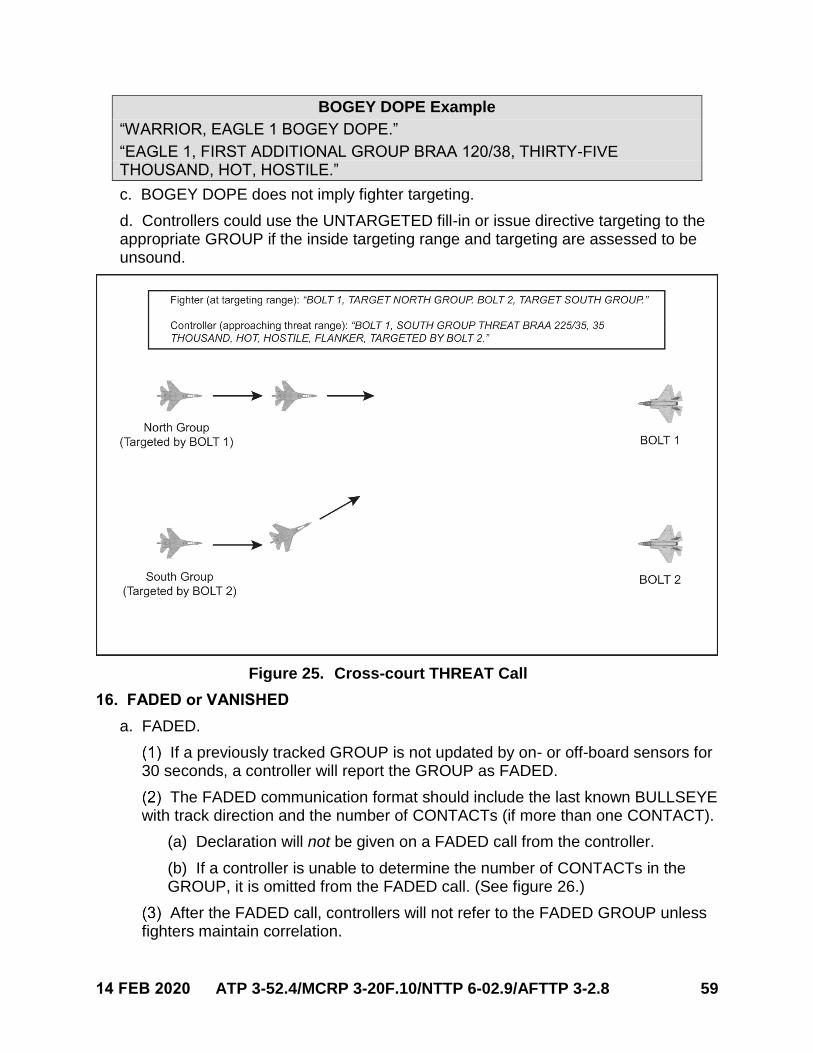
14 FEB 2020 ATP 3-52.4/MCRP 3-20F.10/NTTP 6-02.9/AFTTP 3-2.8 59
BOGEY DOPE Example
“WARRIOR, EAGLE 1 BOGEY DOPE.”
“EAGLE 1, FIRST ADDITIONAL GROUP BRAA 120/38, THIRTY-FIVE THOUSAND, HOT, HOSTILE.”
c. BOGEY DOPE does not imply fighter targeting.
d. Controllers could use the UNTARGETED fill-in or issue directive targeting to theappropriate GROUP if the inside targeting range and targeting are assessed to beunsound.
Figure 25. Cross-court THREAT Call
16. FADED or VANISHED
a. FADED.
If a previously tracked GROUP is not updated by on- or off-board sensors for 30 seconds, a controller will report the GROUP as FADED.
The FADED communication format should include the last known BULLSEYE with track direction and the number of CONTACTs (if more than one CONTACT).
(a) Declaration will not be given on a FADED call from the controller.
(b) If a controller is unable to determine the number of CONTACTs in theGROUP, it is omitted from the FADED call. (See figure 26.)
After the FADED call, controllers will not refer to the FADED GROUP unless fighters maintain correlation.
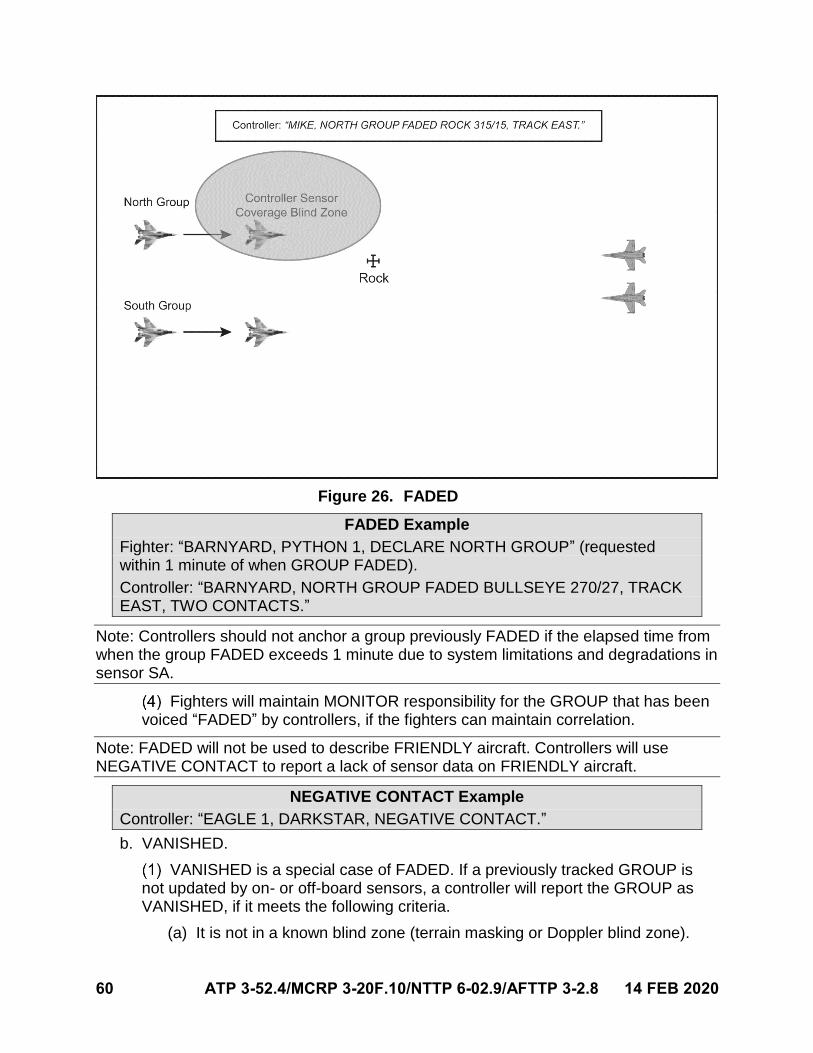
60 ATP 3-52.4/MCRP 3-20F.10/NTTP 6-02.9/AFTTP 3-2.8 14 FEB 2020
Figure 26. FADED
FADED Example
Fighter: “BARNYARD, PYTHON 1, DECLARE NORTH GROUP” (requested within 1 minute of when GROUP FADED).
Controller: “BARNYARD, NORTH GROUP FADED BULLSEYE 270/27, TRACK EAST, TWO CONTACTS.”
Note: Controllers should not anchor a group previously FADED if the elapsed time from when the group FADED exceeds 1 minute due to system limitations and degradations in sensor SA.
Fighters will maintain MONITOR responsibility for the GROUP that has been voiced “FADED” by controllers, if the fighters can maintain correlation.
Note: FADED will not be used to describe FRIENDLY aircraft. Controllers will use NEGATIVE CONTACT to report a lack of sensor data on FRIENDLY aircraft.
NEGATIVE CONTACT Example
Controller: “EAGLE 1, DARKSTAR, NEGATIVE CONTACT.”
b. VANISHED.
VANISHED is a special case of FADED. If a previously tracked GROUP isnot updated by on- or off-board sensors, a controller will report the GROUP asVANISHED, if it meets the following criteria.
(a) It is not in a known blind zone (terrain masking or Doppler blind zone).
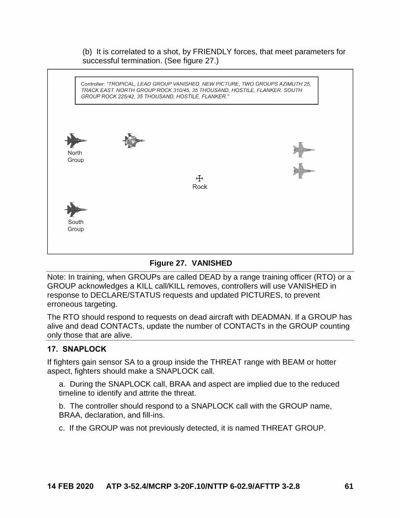
14 FEB 2020 ATP 3-52.4/MCRP 3-20F.10/NTTP 6-02.9/AFTTP 3-2.8 61
(b) It is correlated to a shot, by FRIENDLY forces, that meet parameters forsuccessful termination. (See figure 27.)
Figure 27. VANISHED
Note: In training, when GROUPs are called DEAD by a range training officer (RTO) or a GROUP acknowledges a KILL call/KILL removes, controllers will use VANISHED in response to DECLARE/STATUS requests and updated PICTURES, to prevent erroneous targeting.
The RTO should respond to requests on dead aircraft with DEADMAN. If a GROUP has alive and dead CONTACTs, update the number of CONTACTs in the GROUP counting only those that are alive.
17. SNAPLOCK
If fighters gain sensor SA to a group inside the THREAT range with BEAM or hotter aspect, fighters should make a SNAPLOCK call.
a. During the SNAPLOCK call, BRAA and aspect are implied due to the reducedtimeline to identify and attrite the threat.
b. The controller should respond to a SNAPLOCK call with the GROUP name,BRAA, declaration, and fill-ins.
c. If the GROUP was not previously detected, it is named THREAT GROUP.
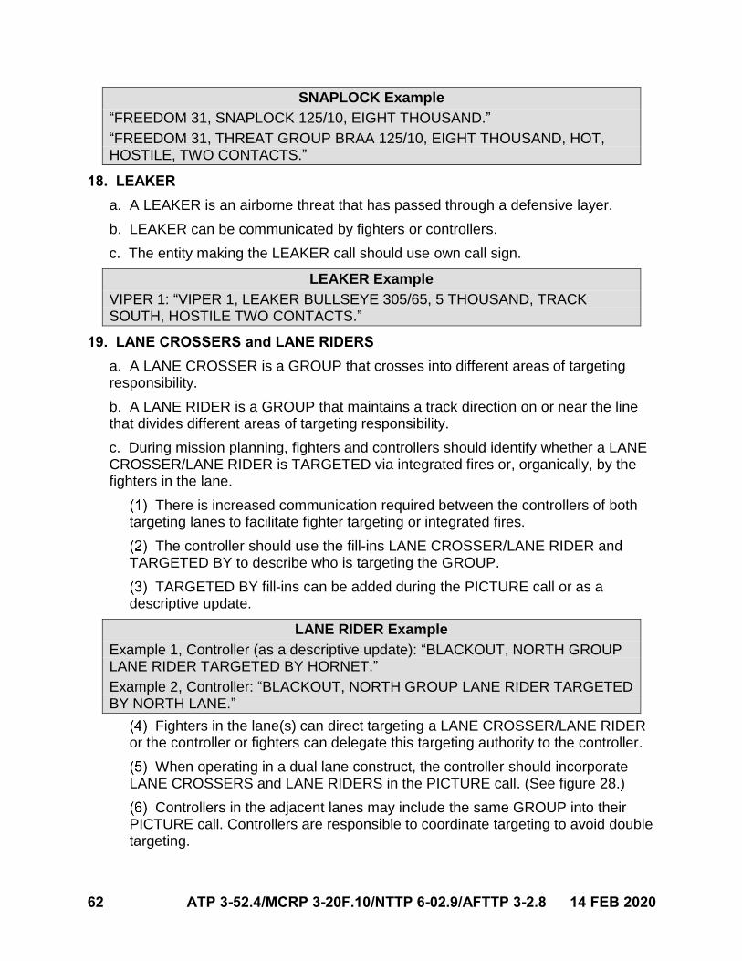
62 ATP 3-52.4/MCRP 3-20F.10/NTTP 6-02.9/AFTTP 3-2.8 14 FEB 2020
SNAPLOCK Example
“FREEDOM 31, SNAPLOCK 125/10, EIGHT THOUSAND.”
“FREEDOM 31, THREAT GROUP BRAA 125/10, EIGHT THOUSAND, HOT, HOSTILE, TWO CONTACTS.”
18. LEAKER
a. A LEAKER is an airborne threat that has passed through a defensive layer.
b. LEAKER can be communicated by fighters or controllers.
c. The entity making the LEAKER call should use own call sign.
LEAKER Example
VIPER 1: “VIPER 1, LEAKER BULLSEYE 305/65, 5 THOUSAND, TRACK SOUTH, HOSTILE TWO CONTACTS.”
19. LANE CROSSERS and LANE RIDERS
a. A LANE CROSSER is a GROUP that crosses into different areas of targetingresponsibility.
b. A LANE RIDER is a GROUP that maintains a track direction on or near the linethat divides different areas of targeting responsibility.
c. During mission planning, fighters and controllers should identify whether a LANECROSSER/LANE RIDER is TARGETED via integrated fires or, organically, by thefighters in the lane.
There is increased communication required between the controllers of both targeting lanes to facilitate fighter targeting or integrated fires.
The controller should use the fill-ins LANE CROSSER/LANE RIDER and TARGETED BY to describe who is targeting the GROUP.
TARGETED BY fill-ins can be added during the PICTURE call or as a descriptive update.
LANE RIDER Example
Example 1, Controller (as a descriptive update): “BLACKOUT, NORTH GROUP LANE RIDER TARGETED BY HORNET.”
Example 2, Controller: “BLACKOUT, NORTH GROUP LANE RIDER TARGETED BY NORTH LANE.”
Fighters in the lane(s) can direct targeting a LANE CROSSER/LANE RIDER or the controller or fighters can delegate this targeting authority to the controller.
When operating in a dual lane construct, the controller should incorporate LANE CROSSERS and LANE RIDERS in the PICTURE call. (See figure 28.)
Controllers in the adjacent lanes may include the same GROUP into their PICTURE call. Controllers are responsible to coordinate targeting to avoid double targeting.
14 FEB 2020 ATP 3-52.4/MCRP 3-20F.10/NTTP 6-02.9/AFTTP 3-2.8 63
Figure 28. LANE RIDER
20. JACKAL
a. JACKAL is not a substitute for fighters gaining sensor SA, but it does providefighters an understanding of where all GROUPs are located.
b. JACKAL allows fighters to loosen initial correlation and can alleviate the controllerfrom having to anchor each GROUP on an intercept.
c. If directive targeting is not to be issued by the controller, fighters can brief for thecontroller to only anchor one GROUP (e.g., NORTH GROUP of a THREE GROUPWALL).
d. The separation and fill-ins provided by the controller will allow fighters to correlatethe exact location of each GROUP even when they do not have sensor SA.
e. During all PICTURE calls, the controller should anchor all GROUPs to betargeted via BULLSEYE, unless otherwise briefed.

64 ATP 3-52.4/MCRP 3-20F.10/NTTP 6-02.9/AFTTP 3-2.8 14 FEB 2020
This page intentionally left blank.
14 FEB 2020 ATP 3-52.4/MCRP 3-20F.10/NTTP 6-02.9/AFTTP 3-2.8 65
Chapter VI
AIR-TO-SURFACE COMMUNICATION
This chapter establishes a communication format for A/S employment. It governs communication fundamentals, format, and integration between aircraft and controllers, independent of MDS or T/M/S. For interflight communication, refer to the appropriate MDS- or T/M/S-specific manual. For more Service-specific tactics and employment considerations, refer to the following weapons schools.
a. USAACE.
b. MAWTS-1.
c. NAWDC N7 (TOPGUN).
d. USAFWS.
Note: For the purpose of this publication, controller is a general term used to define the individual providing tactical control of an intercept or mission. The term aircraft is a general term for air assets executing an A/S mission. Controller and aircraft are used independent of platform or Service.
1. A/S Tasking Serialization
A/S taskings are passed from controllers to aircraft. During a high operation tempo, multiple A/S taskings may be passed. Therefore, it is advantageous to use serialization. Serialization is a system for assigning unique codes to simplify communication. It can use letters, numbers, or symbols to identify a large set of information. Serialization is applied to each task in the order of creation and does not imply priority or confidence.
a. Plan for the mission to include the A/S tasking serialization technique.
b. The labeling convention should use the ATO day and two-digit numericsequencing. For example:
AA01 is the first task of ATO day AA.
This designator should precede the tasking message.
Digital messages should end with “EOM” meaning “end of message”. This indicates receipt of all digital message data (e.g., “[aircraft call sign] AA01 [tasking message text] EOM”).
2. A/S Tasking Format
A/S taskings can be passed as full or partial digital, or voice.
a. Taskings should pass the minimum information required to safely and efficientlyaccomplish the mission.
b. Taskings should include the following information, when applicable.
Call sign of the asset being tasked.
Task type (e.g., TARGET, INVESTIGATE, or SMACK).
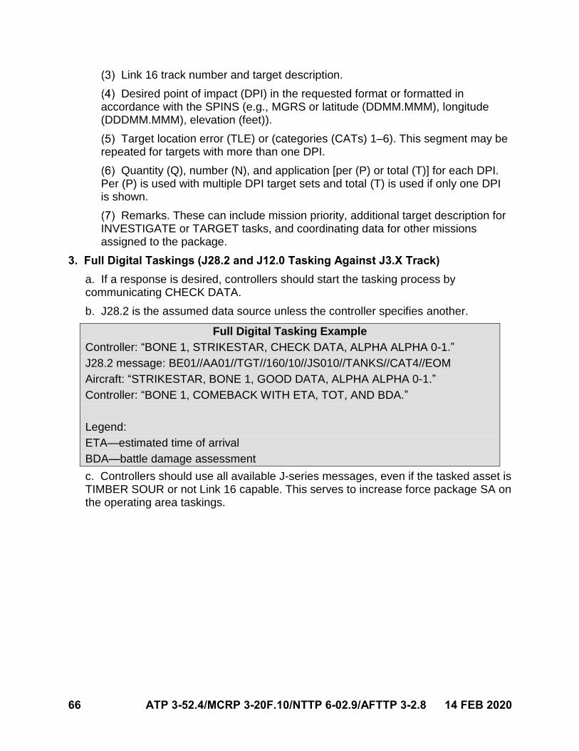
66 ATP 3-52.4/MCRP 3-20F.10/NTTP 6-02.9/AFTTP 3-2.8 14 FEB 2020
Link 16 track number and target description.
Desired point of impact (DPI) in the requested format or formatted in accordance with the SPINS (e.g., MGRS or latitude (DDMM.MMM), longitude (DDDMM.MMM), elevation (feet)).
Target location error (TLE) or (categories (CATs) 1–6). This segment may be repeated for targets with more than one DPI.
Quantity (Q), number (N), and application [per (P) or total (T)] for each DPI. Per (P) is used with multiple DPI target sets and total (T) is used if only one DPI is shown.
Remarks. These can include mission priority, additional target description for INVESTIGATE or TARGET tasks, and coordinating data for other missions assigned to the package.
3. Full Digital Taskings (J28.2 and J12.0 Tasking Against J3.X Track)
a. If a response is desired, controllers should start the tasking process bycommunicating CHECK DATA.
b. J28.2 is the assumed data source unless the controller specifies another.
Full Digital Tasking Example
Controller: “BONE 1, STRIKESTAR, CHECK DATA, ALPHA ALPHA 0-1.”
J28.2 message: BE01//AA01//TGT//160/10//JS010//TANKS//CAT4//EOM
Aircraft: “STRIKESTAR, BONE 1, GOOD DATA, ALPHA ALPHA 0-1.”
Controller: “BONE 1, COMEBACK WITH ETA, TOT, AND BDA.”
Legend:
ETA—estimated time of arrival
BDA—battle damage assessment
c. Controllers should use all available J-series messages, even if the tasked asset isTIMBER SOUR or not Link 16 capable. This serves to increase force package SA onthe operating area taskings.
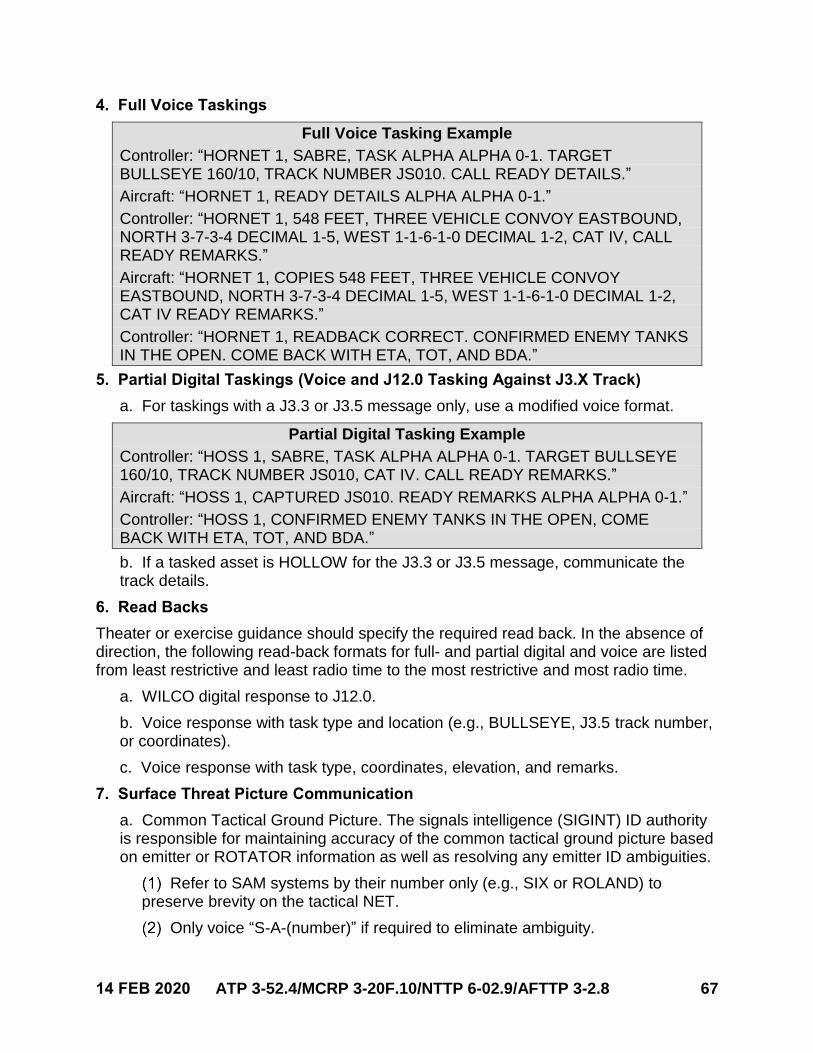
14 FEB 2020 ATP 3-52.4/MCRP 3-20F.10/NTTP 6-02.9/AFTTP 3-2.8 67
4. Full Voice Taskings
Full Voice Tasking Example
Controller: “HORNET 1, SABRE, TASK ALPHA ALPHA 0-1. TARGET BULLSEYE 160/10, TRACK NUMBER JS010. CALL READY DETAILS.”
Aircraft: “HORNET 1, READY DETAILS ALPHA ALPHA 0-1.”
Controller: “HORNET 1, 548 FEET, THREE VEHICLE CONVOY EASTBOUND, NORTH 3-7-3-4 DECIMAL 1-5, WEST 1-1-6-1-0 DECIMAL 1-2, CAT IV, CALL READY REMARKS.”
Aircraft: “HORNET 1, COPIES 548 FEET, THREE VEHICLE CONVOY EASTBOUND, NORTH 3-7-3-4 DECIMAL 1-5, WEST 1-1-6-1-0 DECIMAL 1-2, CAT IV READY REMARKS.”
Controller: “HORNET 1, READBACK CORRECT. CONFIRMED ENEMY TANKS IN THE OPEN. COME BACK WITH ETA, TOT, AND BDA.”
5. Partial Digital Taskings (Voice and J12.0 Tasking Against J3.X Track)
a. For taskings with a J3.3 or J3.5 message only, use a modified voice format.
Partial Digital Tasking Example
Controller: “HOSS 1, SABRE, TASK ALPHA ALPHA 0-1. TARGET BULLSEYE 160/10, TRACK NUMBER JS010, CAT IV. CALL READY REMARKS.”
Aircraft: “HOSS 1, CAPTURED JS010. READY REMARKS ALPHA ALPHA 0-1.”
Controller: “HOSS 1, CONFIRMED ENEMY TANKS IN THE OPEN, COME BACK WITH ETA, TOT, AND BDA.”
b. If a tasked asset is HOLLOW for the J3.3 or J3.5 message, communicate thetrack details.
6. Read Backs
Theater or exercise guidance should specify the required read back. In the absence of direction, the following read-back formats for full- and partial digital and voice are listed from least restrictive and least radio time to the most restrictive and most radio time.
a. WILCO digital response to J12.0.
b. Voice response with task type and location (e.g., BULLSEYE, J3.5 track number,or coordinates).
c. Voice response with task type, coordinates, elevation, and remarks.
7. Surface Threat Picture Communication
a. Common Tactical Ground Picture. The signals intelligence (SIGINT) ID authorityis responsible for maintaining accuracy of the common tactical ground picture basedon emitter or ROTATOR information as well as resolving any emitter ID ambiguities.
Refer to SAM systems by their number only (e.g., SIX or ROLAND) to preserve brevity on the tactical NET.
Only voice “S-A-(number)” if required to eliminate ambiguity.
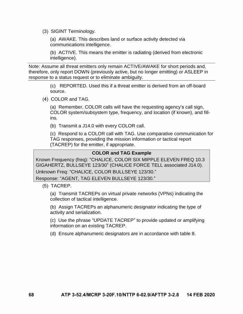
68 ATP 3-52.4/MCRP 3-20F.10/NTTP 6-02.9/AFTTP 3-2.8 14 FEB 2020
SIGINT Terminology.
(a) AWAKE. This describes land or surface activity detected viacommunications intelligence.
(b) ACTIVE. This means the emitter is radiating (derived from electronicintelligence).
Note: Assume all threat emitters only remain ACTIVE/AWAKE for short periods and, therefore, only report DOWN (previously active, but no longer emitting) or ASLEEP in response to a status request or to eliminate ambiguity.
(c) REPORTED. Used this if a threat emitter is derived from an off-boardsource.
COLOR and TAG.
(a) Remember, COLOR calls will have the requesting agency’s call sign,COLOR system/subsystem type, frequency, and location (if known), and fill-ins.
(b) Transmit a J14.0 with every COLOR call.
(c) Respond to a COLOR call with TAG. Use comparative communication forTAG responses, providing the mission information or tactical report(TACREP) for the emitter, if appropriate.
COLOR and TAG Example
Known Frequency (freq): “CHALICE, COLOR SIX MIPPLE ELEVEN FREQ 10.3 GIGAHERTZ, BULLSEYE 123/30” (CHALICE FORCE TELL associated J14.0).
Unknown Freq: “CHALICE, COLOR BULLSEYE 123/30.”
Response: “AGENT, TAG ELEVEN BULLSEYE 123/30.”
TACREP.
(a) Transmit TACREPs on virtual private networks (VPNs) indicating thecollection of tactical intelligence.
(b) Assign TACREPs an alphanumeric designator indicating the type ofactivity and serialization.
(c) Use the phrase “UPDATE TACREP” to provide updated or amplifyinginformation on an existing TACREP.
(d) Ensure alphanumeric designators are in accordance with table 8.
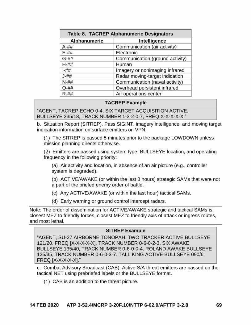
14 FEB 2020 ATP 3-52.4/MCRP 3-20F.10/NTTP 6-02.9/AFTTP 3-2.8 69
Table 8. TACREP Alphanumeric Designators
Alphanumeric Intelligence
A-## Communication (air activity)
E-## Electronic
G-## Communication (ground activity)
H-## Human
I-## Imagery or nonimaging infrared
J-## Radar moving-target indication
N-## Communication (naval activity)
O-## Overhead persistent infrared
R-## Air operations center
TACREP Example
“AGENT, TACREP ECHO 0-4, SIX TARGET ACQUISITION ACTIVE, BULLSEYE 235/18, TRACK NUMBER 1-3-2-0-7, FREQ X-X-X-X-X.”
b. Situation Report (SITREP). Pass SIGINT, imagery intelligence, and moving targetindication information on surface emitters on VPN.
The SITREP is passed 5 minutes prior to the package LOWDOWN unless mission planning directs otherwise.
Emitters are passed using system type, BULLSEYE location, and operating frequency in the following priority:
(a) Air activity and location, in absence of an air picture (e.g., controllersystem is degraded).
(b) ACTIVE/AWAKE (or within the last 8 hours) strategic SAMs that were nota part of the briefed enemy order of battle.
(c) Any ACTIVE/AWAKE (or within the last hour) tactical SAMs.
(d) Early warning or ground control intercept radars.
Note: The order of dissemination for ACTIVE/AWAKE strategic and tactical SAMs is: closest MEZ to friendly forces, closest MEZ to friendly axis of attack or ingress routes, and most lethal.
SITREP Example
“AGENT, SU-27 AIRBORNE TONOPAH. TWO TRACKER ACTIVE BULLSEYE 121/20, FREQ [X-X-X-X-X], TRACK NUMBER 0-6-0-2-3. SIX AWAKE BULLSEYE 135/40, TRACK NUMBER 0-6-0-0-4. ROLAND AWAKE BULLSEYE 125/35, TRACK NUMBER 0-6-0-3-7. TALL KING ACTIVE BULLSEYE 090/6 FREQ [X-X-X-X-X].”
c. Combat Advisory Broadcast (CAB). Active S/A threat emitters are passed on thetactical NET using prebriefed labels or the BULLSEYE format.
CAB is an addition to the threat picture.
70 ATP 3-52.4/MCRP 3-20F.10/NTTP 6-02.9/AFTTP 3-2.8 14 FEB 2020
Command and control agencies will relay CAB information received from VPN to the appropriate NETs.
CAB Example
CAB from BANDSAW on primary NET: “BANDSAW, TWO ACTIVE BULLSEYE 035/8” or “BANDSAW, NORTH TWO ACTIVE.”
d. Imminent Threat Warning (ITW). ITW is a S/A threat warning to a friendly asset.
An ITW is passed when a friendly aircraft is within 5 nm of the maximum intercept range of any ACTIVE, AWAKE, launching, or firing threat.
An ITW is prefaced with the aircraft call sign or the BULLSEYE position of the friendly aircraft and uses prebriefed labels or the BULLSEYE format for the threat description.
Note: When communicating with United States Army or United States Marine Corps rotary-wing aircraft and UASs, pass surface threat information in MGRS, if known. Attempt to provide at least a six-digit grid.
No ITW is required if an aircraft has reported MUD, DEFENDING, or SINGER to the specified threat.
ITW procedures are coordinated for low-observable assets during mission planning.
ITW Example
“EAGLE 1, AGENT, ELEVEN ACTIVE BULLSEYE 015/9.”
e. TRESPASS. Aircraft, controllers, and agencies will voice TRESPASS when anaircraft is within a not-previously-known SAM MEZ (e.g., a POP-UP SAM). If able,aircraft, controllers, or sensor operators, also, will voice the BULLSEYE location ofthe SAM.
TRESPASS Example
“RAMBO 1, TRESPASS FIFTEEN BULLSEYE 155/52.”
8. Threat Reaction Communication
a. Targeted aircraft should communicate S/A threat reactions on mission tacticalNETs:
If it enables, or aircraft requires, reactive suppression of enemy air defenses (SEAD).
To enhance the common tactical picture for other mission or package assets.
b. These transmissions should be in either a low- or high-fidelity format. Minimumaccuracy to consider a threat “high fidelity” is a 5 nm, semi-major ellipse, or asmission-planned.
14 FEB 2020 ATP 3-52.4/MCRP 3-20F.10/NTTP 6-02.9/AFTTP 3-2.8 71
Low-Fidelity Format
Call sign, radar warning receiver indication, bearing, DEFENDING with cardinal direction, ownship BULLSEYE.
Low-Fidelity Example
“HORNET 1, SINGER 11, BEARING 3-6-0, DEFENDING WEST, BULLSEYE 345/30.”
High Fidelity Format
Call sign, radar warning receiver indication, surface-to-air threat BULLSEYE/LOCATION, DEFENDING with cardinal direction.
High Fidelity Example
“BOLT 1, SINGER 11 BULLSEYE 360/32, DEFENDING WEST.”
9. SEAD Contracts
a. SEAD aircraft should provide one of four responses to a DEFENDING call:
HARM INBOUND. High-speed antiradiation missile (HARM) already employed.
MAGNUM. Launch of FRIENDLY antiradiation missile (ARM).
EMPTY. No emitters of interest detected.
ARIZONA. No ARM ordnance remaining.
b. SNIPER and SLAPSHOT Communication.
SNIPER.
(a) This is a directive call from the SEAD package/flight lead.
(b) It indicates a specific aircraft/element should employ an ARM against arange-known S/A threat.
SNIPER Example
Directive Call: “STORM, SNIPER 11 BULLSEYE 360/32.”
Response: “STORM 2, MAGNUM 11 BULLSEYE 360/32.”
SLAPSHOT.
(a) This is a directive call indicating an aircraft or element should immediatelyemploy the best-available ARM on the specified threat bearing.
(b) SLAPSHOT assumes the S/A threat range is unknown.
SLAPSHOT Example
Directive Call: “STORM, SLAPSHOT 15 BEARING 3-1-7.”
Response: “STORM 2, HARM INBOUND.”
72 ATP 3-52.4/MCRP 3-20F.10/NTTP 6-02.9/AFTTP 3-2.8 14 FEB 2020
SEAD players respond with HARM INBOUND, MAGNUM, EMPTY, or ARIZONA.
c. Electronic Attack (EA) Communication. Aircraft should direct or communicate EAusing the following terminology:
EA Examples
Directing EA: “BOLT 1, JAM 11, BULLSEYE 360/32.”
Informative EA: “BOLT 1, CANYON 11, BULLSEYE 360/32.”
Ceasing EA: “BOLT 1, CLAM 11, BULLSEYE 360/32”.
10. Find, Fix, Track, Target, Engage, Assess (F2T2EA) Contracts
a. Find. The MC is responsible to hold or delegate authority for aircraft or elementsearch contracts.
Find Example
MC: “BOLT, WORK 6 BULLSEYE 360/34.”
Aircraft: “BOLT 1, WORKING 6 BULLSEYE 360/34.”
MC: “HOSS, MAP 15 BULLSEYE 317/17.”
Aircraft: “HOSS 3, MAPPING 15 BULLSEYE 317/17.”
MC: “CONAN, INVESTIGATE TRACK NUMBER 1-2-3-4-5.”
Aircraft: “CONAN.”
b. Fix.
Locate the threat and pass TLE or ellipse (semi-major) quality with the FIXED call.
Use the following terms to delineate fix quality:
(a) Low Accuracy. Inside 1 nm.
Low Accuracy Example
“BOLT 1, 6 FIXED BULLSEYE 360/32, LOW ACCURACY.”
(b) High Accuracy. Inside 1,000 feet.
High Accuracy Example
“AGENT 6, FIXED BULLSEYE 360/32, HIGH ACCURACY, TRACK NUMBER 0-3-0-0-7.”
(c) TARGETABLE. CAT II low is assumed.
Any other TLE is added as a fill-in.
Controllers should populate a J3.5 over individual J12.6s once they arecalled TARGETABLE.
14 FEB 2020 ATP 3-52.4/MCRP 3-20F.10/NTTP 6-02.9/AFTTP 3-2.8 73
Targetable Examples
“HOSS 3, FIXED SCRUM HALF BULLSEYE 3-1-7/17, TARGETABLE.”
“AGENT, SCRUM HALF BULLSEYE 3-1-7/17, TARGETABLE, TRACK NUMBER 1-6-1-7-3.”
c. TRACK.
TRACKING is necessary for custody of a threat, SAM, high-value target, or other surface entity.
The MC, or PC, can direct an asset to TRACK, SCAN, or MONITOR an area or object.
(a) TRACK. This is a directive call assigning responsibility to maintainsensors or a visual on a defined object or area to an asset.
(b) MONITOR.
Maintain sensor awareness on a specified GROUP or object. It impliestactically significant changes are communicated.
For maritime operations, this means maintain contact or targetinginformation on a maritime surface contact.
(c) SCAN. Search the indicated sector and report any CONTACTs.
Assets can respond with OCCUPIED, TALLY, TRACKING, CAPTURED, or MONITORING, if able to TRACK.
TALLY Example
MC: “HOSS, TRACK THREE VEHICLE CONVOY BULLSEYE 300/45, MOVING WEST, TRACK NUMBER 3-4-3-4-5.”
Aircraft: “HOSS 1, TALLY.”
CAPTURED Example
MC: “SABRE, TRACK T-72 COLUMN BULLSEYE 050/55, MOVING NORTH.”
Aircraft: “SABRE, CAPTURED, TRACK NUMBER 2-2-2-2-2.”
MONITORING Example
MC: “WEASEL 51, MONITOR 11, TRACK NUMBER 1-1-1-1-1.”
Aircraft: “WEASEL 51, MONITORING 11, BULLSEYE 316/60.”
Assets can respond with NO JOY if they have not found the object.
d. TARGET and Attack Game Plan.
The purpose of the ATTACK game plan is to:
(a) Establish a SORT, especially across multiple formations.
(b) To establish weapon pairings.
74 ATP 3-52.4/MCRP 3-20F.10/NTTP 6-02.9/AFTTP 3-2.8 14 FEB 2020
(c) Reference locations (e.g., predetermined points, anchor references withdistance, or BULLSEYE).
(d) Time and deconfliction prior to PUSHING as a force package.
This game plan should also delineate responsibilities.
Note: The game plan can be communicated via Link 16, and each player needs only to acknowledge GOOD DATA.
Attack Game Plan Example
In the following example, RAMBO is the MC and escort PC, HORNET is the strike PC, BOLT is a strike flight lead, and PYTHON is the SEAD PC.
RAMBO (MC): “HORNET, BOLT, PYTHON, STANDBY GAME PLAN.”
Flight Leads: “HORNET.” “BOLT.” “PYTHON.”
RAMBO: “HORNET, TARGET AND SCAN ALPHA ALPHA 0-1, TWO VEHICLE
CONVOY BULLSEYE 275/69, MOVING SOUTH, BEST. PUSH AT
21:17 FROM RED OSCAR.”
“BOLT, COVER ALPHA ALPHA 0-1.”
“RAMBO ESCORT AND PYTHON SEAD PER BRIEF.”
Flight Leads: “HORNET.” “BOLT.” “PYTHON.”
e. Engage.
The aircraft executing the attack will call ATTACKING at the push, with a TOT, once all players have acknowledged the game plan.
Aircraft should call releases with time of flight and IMPACT, when able.
(a) If an aircraft has additional support requirements for the A/S weapon,provide this as a fill-in (e.g., LASING or SCANNING).
ATTACKING Example
“HORNET, CAPTURED ALPHA ALPHA 0-1. ATTACKING TOT 21:21:15.”
“HORNET 1, ONE WEAPON AWAY ALPHA ALPHA 0-1, 45 SECONDS,
LASING.”
“HORNET 1, SPLASH ALPHA ALPHA 0-1.”
f. Assess.
SCAN can be used to direct the weapon effects assessment.
(a) SCAN means to search the indicated sector and report any CONTACTs.
(b) Once the target or object has been acquired and is being tracked with anonboard sensor or visually, respond with CAPTURED or TALLY.
(c) If unable to find the target or object, relay VACANT, EMPTY, or NO JOY.
To describe the weapon results, use successful or unsuccessful.
14 FEB 2020 ATP 3-52.4/MCRP 3-20F.10/NTTP 6-02.9/AFTTP 3-2.8 75
(a) Successful. Desired weapon effects were achieved. DROPPING orDROP can be used to complete the F2T2EA chain.
DROPPING is an informative call from a tasked aircraft that the aircrewis no longer targeted to tasking.
Weapons Effects Achieved (DROPPING) Example
HORNET: “HORNET SPLASH ALPHA ALPHA 0-1 SUCCESSFUL. DROPPING
ALPHA ALPHA 0-1.”
DROP is a directive call to remove a ground target from the tacticalground picture.
Weapons Effects Achieved (DROP) Example
HORNET: “HORNET SPLASH ALPHA ALPHA 0-1 SUCCESSFUL.”
HORNET: “DARKSTAR DROP ALPHA ALPHA 0-1, T-N 5-2-3-4-2.”
(b) Unsuccessful. Desired weapon effects were not achieved.
Informative fill-ins can assist when relaying Unsuccessful.
“Unsuccessful CLEAN” (i.e., no visible battle damage) indicates thetarget sustained no damage or no weapon impact was noted.
“Unsuccessful HIT” indicates weapon impact was noted within a lethaldistance, but the effects were not achieved.
Weapons Effects Not Achieved Example
HORNET: “HORNET, SPLASH ALPHA ALPHA 0-1, UNSUCCESSFUL HIT.”
Reattack.
(a) Plan reattack options during mission planning, if an asset is capable of areal-time hit assessment.
(b) To facilitate rapid reattack, consider using SCAN with COVER.
COVER. This is a directive call to be ready for reattack or reengage, ifweapons effects are not achieved.
HOUNDDOG. This call is in response to COVER, indicating the directedaircraft is in a position to employ weapons.
Reattack Option Example
MC: “HORNET TARGET AND SCAN ALPHA ALPHA 0-1.
BOLT COVER ALPHA ALPHA 0-1.”
HORNET: “HORNET 1, ONE WEAPON AWAY ALPHA ALPHA 0-1,
45 SECONDS, LASING AND SCANNING.”
HORNET: “HORNET, SPLASH ALPHA ALPHA 0-1, UNSUCCESSFUL HIT.”
BOLT: “BOLT, HOUNDDOG ALPHA ALPHA 0-1.”
MC: “BOLT, REATTACK, ALPHA ALPHA 0-1.”

76 ATP 3-52.4/MCRP 3-20F.10/NTTP 6-02.9/AFTTP 3-2.8 14 FEB 2020
This page intentionally left blank.
14 FEB 2020 ATP 3-52.4/MCRP 3-20F.10/NTTP 6-02.9/AFTTP 3-2.8 77
REFERENCES
JOINT PUBLICATIONS
DOD Dictionary of Military Associated Terms, as of January 2020JP 1-0, Joint Personnel Support, 31 May 2016
JP 3-0, Joint Operations, 17 January 2017 (Incorporated Change 1, 22 October 2018)
JP 3-09.3, Close Air Support, 10 June 2019
JP 3-52, Joint Airspace Control, 13 November 2014

78 ATP 3-52.4/MCRP 3-20F.10/NTTP 6-02.9/AFTTP 3-2.8 14 FEB 2020
This page intentionally left blank.
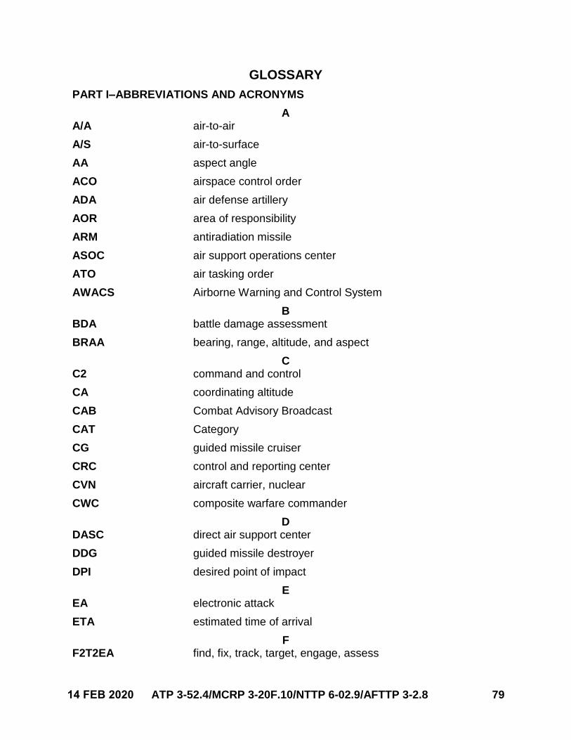
14 FEB 2020 ATP 3-52.4/MCRP 3-20F.10/NTTP 6-02.9/AFTTP 3-2.8 79
GLOSSARY
PART I–ABBREVIATIONS AND ACRONYMS
A A/A air-to-air
A/S air-to-surface
AA aspect angle
ACO airspace control order
ADA air defense artillery
AOR area of responsibility
ARM antiradiation missile
ASOC air support operations center
ATO air tasking order
AWACS Airborne Warning and Control System
B BDA battle damage assessment
BRAA bearing, range, altitude, and aspect
C C2 command and control
CA coordinating altitude
CAB Combat Advisory Broadcast
CAT Category
CG guided missile cruiser
CRC control and reporting center
CVN aircraft carrier, nuclear
CWC composite warfare commander
D DASC direct air support center
DDG guided missile destroyer
DPI desired point of impact
E EA electronic attack
ETA estimated time of arrival
F F2T2EA find, fix, track, target, engage, assess
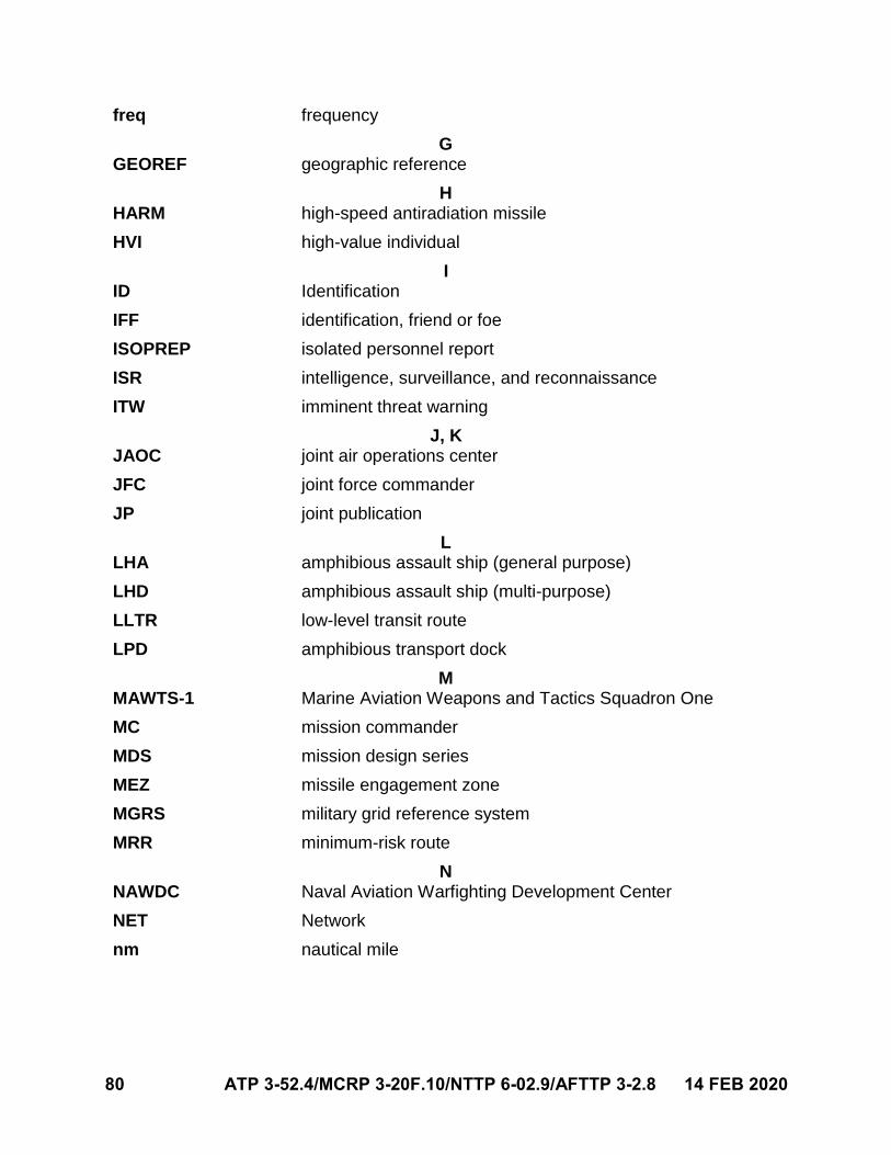
80 ATP 3-52.4/MCRP 3-20F.10/NTTP 6-02.9/AFTTP 3-2.8 14 FEB 2020
freq frequency
G GEOREF geographic reference
H HARM high-speed antiradiation missile
HVI high-value individual
I ID Identification
IFF identification, friend or foe
ISOPREP isolated personnel report
ISR intelligence, surveillance, and reconnaissance
ITW imminent threat warning
J, K JAOC joint air operations center
JFC joint force commander
JP joint publication
L LHA amphibious assault ship (general purpose)
LHD amphibious assault ship (multi-purpose)
LLTR low-level transit route
LPD amphibious transport dock
M MAWTS-1 Marine Aviation Weapons and Tactics Squadron One
MC mission commander
MDS mission design series
MEZ missile engagement zone
MGRS military grid reference system
MRR minimum-risk route
N NAWDC Naval Aviation Warfighting Development Center
NET Network
nm nautical mile
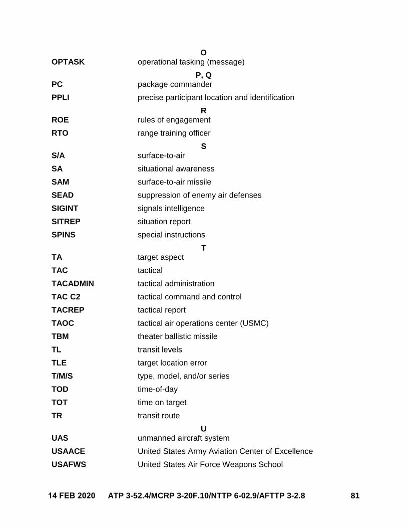
14 FEB 2020 ATP 3-52.4/MCRP 3-20F.10/NTTP 6-02.9/AFTTP 3-2.8 81
O OPTASK operational tasking (message)
P, Q PC package commander
PPLI precise participant location and identification
R ROE rules of engagement
RTO range training officer
S S/A surface-to-air
SA situational awareness
SAM surface-to-air missile
SEAD suppression of enemy air defenses
SIGINT signals intelligence
SITREP situation report
SPINS special instructions
T TA target aspect
TAC tactical
TACADMIN tactical administration
TAC C2 tactical command and control
TACREP tactical report
TAOC tactical air operations center (USMC)
TBM theater ballistic missile
TL transit levels
TLE target location error
T/M/S type, model, and/or series
TOD time-of-day
TOT time on target
TR transit route
U UAS unmanned aircraft system
USAACE United States Army Aviation Center of Excellence
USAFWS United States Air Force Weapons School
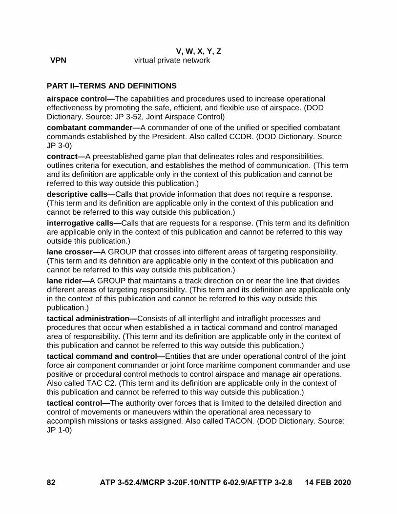
82 ATP 3-52.4/MCRP 3-20F.10/NTTP 6-02.9/AFTTP 3-2.8 14 FEB 2020
V, W, X, Y, Z VPN virtual private network
PART II–TERMS AND DEFINITIONS
airspace control—The capabilities and procedures used to increase operational effectiveness by promoting the safe, efficient, and flexible use of airspace. (DOD Dictionary. Source: JP 3-52, Joint Airspace Control)
combatant commander—A commander of one of the unified or specified combatant commands established by the President. Also called CCDR. (DOD Dictionary. Source JP 3-0)
contract—A preestablished game plan that delineates roles and responsibilities, outlines criteria for execution, and establishes the method of communication. (This term and its definition are applicable only in the context of this publication and cannot be referred to this way outside this publication.)
descriptive calls—Calls that provide information that does not require a response. (This term and its definition are applicable only in the context of this publication and cannot be referred to this way outside this publication.)
interrogative calls—Calls that are requests for a response. (This term and its definition are applicable only in the context of this publication and cannot be referred to this way outside this publication.)
lane crosser—A GROUP that crosses into different areas of targeting responsibility. (This term and its definition are applicable only in the context of this publication and cannot be referred to this way outside this publication.)
lane rider—A GROUP that maintains a track direction on or near the line that divides different areas of targeting responsibility. (This term and its definition are applicable only in the context of this publication and cannot be referred to this way outside this publication.)
tactical administration—Consists of all interflight and intraflight processes and procedures that occur when established a in tactical command and control managed area of responsibility. (This term and its definition are applicable only in the context of this publication and cannot be referred to this way outside this publication.)
tactical command and control—Entities that are under operational control of the joint force air component commander or joint force maritime component commander and use positive or procedural control methods to control airspace and manage air operations. Also called TAC C2. (This term and its definition are applicable only in the context of this publication and cannot be referred to this way outside this publication.)
tactical control—The authority over forces that is limited to the detailed direction and control of movements or maneuvers within the operational area necessary to accomplish missions or tasks assigned. Also called TACON. (DOD Dictionary. Source: JP 1-0)
14 FEB 2020 ATP 3-52.4/MCRP 3-20F.10/NTTP 6-02.9/AFTTP 3-2.8 83
ATP 3-52.4 MCRP 3-20F.10
NTTP 6-02.9 AFTTP 3-2.8
14 February 2020
DISTRIBUTION: Active Army, Army National Guard, and US Army Reserve: Not to be distributed. Electronic means only.
By Order of the Secretary of the Air Force
BRAD M. SULLIVAN Major General, USAF Commander Curtis E. LeMay Center for Doctrine Development and Education
ACCESSIBILITY: Publications and forms are available on the e-Publishing website at www.e-publishing.af.mil for downloading or ordering.
RELEASABILITY: Distribution approved for public release; distribution is unlimited.
2004307

MARINE CORPS PCN: 144 000285 00 PIN: 206304-000