Embed Size (px)
Citation preview
Multi-robot Mapping of Lava Tubes
X. Huang, J. Yang, M. Storrie-Lombardi, G. Lyzenga, C. M. Clark
Abstract Terrestrial planetary bodies such as Mars and the Moon are known to har-bor volcanic terrain with enclosed lava tube conduits and caves. The shielding fromcosmic radiation that they provide makes them a potentially hospitable habitat forlife. This motivates the need to explore such lava tubes and assess their potential aslocations for future human outposts. Such exploration will likely be conducted byautonomous mobile robots before humans, and this paper proposes a novel mecha-nism for constructing maps of lava tubes using a multi-robot platform. A key issuein mapping lava tubes is the presence of fine sand that can be found at the bottomof most tubes, as observed on earth. This fine sand makes robot odometry measure-ments highly prone to errors. To address this issue, this work leverages the abilityof a multi-robot system to measure the relative motion of robots using laser rangefinders. Mounted on each robot is a 2D laser range finder attached to a servo to en-able 3D scanning. The lead robot has an easily recognized target panel that allowsthe follower robot to measure both the relative distance and orientation betweenrobots. First, these measurements are used to enable 2D (SLAM) of a lava tube.Second, the 3D range measurements are fused with the 2D maps via ICP algorithmsto construct full 3D representations. This method of 3D mapping does not requireodometry measurements or fine-scale environment features. It was validated in abuilding hallway system, demonstrating successful loop closure and mapping errorson the order of 0.63 meters over a 79.64 meters long loop. Error growth modelswere determined experimentally that indicate the robot localization errors grow ata rate of 20 mm per meter travelled, although this is also dependent on the relativeorientation of robots localizing each other. Finally, the system was deployed in alava tube located at Pisgah Crater in the Mojave Desert, CA. Data was collectedto generate a full 3D map of the lava tube. Comparison with known measurementstaken between two ends of the lava tube indicates the mapping errors were on theorder of 1.03 m after the robot travelled 32 meters.
Xin Huang, Jingbin Yang, Michael Storrie-Lombardi, Gregory Lyzenga, Christopher M. ClarkHarvey Mudd College, Claremont, California 91711 e-mail: {xhuang, jyang, mstorrielombardi,lyzenga, clark}@hmc.edu
1
2 X. Huang, J. Yang, M. Storrie-Lombardi, G. Lyzenga, C. M. Clark
1 Introduction
It is understood that within our solar system, Mars shares an environment similarin many respects to that of Earth, and it is possible that there might exist traces oflife. The surface of Mars is relatively inhospitable and is constantly bombarded bycosmic radiation due to the thin atmosphere and lack of planetary magnetic field.Furthermore, the surface temperature ranges from 160 Kelvin to 215 Kelvin fromthe equator to the poles. The temperature also fluctuates greatly within a day. Theupper few kilometers of the lithosphere are likely to be frozen, with the exceptionof volcanically active areas. Despite these harsh conditions, many scientists pre-dict the existence of a saline groundwater system in the shallow subsurface of theplanet, and therefore the subsurface may provide or may have provided a suitableenvironment for life. NASA’s Astrobiology Roadmap objectives include investigat-ing biosignatures in subsurface rocks, modeling subsurface habitable environments,and developing robotic drilling systems to access subsurface environments on Mars[7].
Lava tubes on Mars have gained considerable interest in the astrobiological com-munity because they offer protection from the harsh conditions experienced on theplanet’s surface. There have been many attempts to characterize these lava tubes todetermine the best sites for future exploration and to study the geomicrobiology inlava tubes. To achieve these goals remote-sensing techniques are required [7]. Thelava tubes often have many openings, uneven terrain and variation in floor texture.Therefore, while radar instruments have already been used to drill to the subsurfaceto detect such characteristics, existing sensing methods often lack the resolutionnecessary to detect exact positions of interest in each individual lava tube.
These challenges motivate the goal of developing autonomous robots that canexplore lava tubes and conduct in-situ scientific measurements. Such robots wouldneed to construct 3D maps of the tubes to not only allow the robot to localize in-situsample measurements with respect to a coordinate frame fixed to the tube, but also toenable the robot to localize itself with respect to the tube and carry out autonomousrobot navigation.
Constructing 3D maps with robots has been well studied in the SimultaneousLocalization and Mapping (SLAM) community. Many SLAM strategies have used asingle robot that fuses odometry and range measurements via filtering algorithms tolocalize the robot and map the environment [1, 8]. While these methods are reliable,they are limited by the conditions of the exploration environment. The susceptibilityof the encoder odometry measurements to error resulting from the fine sand foundon the lava tube floor further challenges the SLAM problem.
Proposed here is a multi-robot mapping framework that allows robots to coop-eratively map lava tubes which a) have poor odometry measurements due to thefine sand of the tube floor, and b) lack fine-scale features that reduce dead reck-oning errors. Section 2 of this paper presents related work. A three-step solutioncalled Platoon SLAM is proposed in Section 3, where in the first two steps rangefinder measurements of the relative distance and bearing-angle orientations betweenrobots are used to update their positions, and in the last step these updated positions
Multi-robot Mapping of Lava Tubes 3
(a) (b)
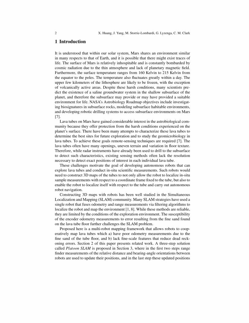
Fig. 1: Image of the Jaguar robot (a) at the entrance of a lava tube (b) on the sandyground
are used to seed ICP algorithm queries, that both localize the robot in 2D and con-struct maps in 3D. Implementation of these techniques are documented in Section 4,where results from hallway and lava tube mapping scenarios are presented. Finally,conclusions from these results are drawn in Section 5 and possible future work isproposed in 6.
2 Background
The problem of Simultaneous Localization and Mapping (SLAM) involves con-structing a map of an unknown environment while localizing the position of therobot. SLAM is a maturing research area, with work most related to this project in-cluding advancements made in the sub-disciplines of 3D SLAM, ICP, 3D mappingin tube like structures, and multi-robot 3D SLAM.
A variety of approaches to 3D mapping in SLAM have been implemented thatcombine different localization and mapping techniques. Initially, 3D maps werebuilt using multiple 2D scanners with different orientations to construct the 3D map.Thrun et. al. [11] used measurements from two laser scanners, oriented perpendic-ular with respect to each other to form 3D point clouds. However other methodsmentioned below give higher resolution of the generated 3D map, including visualSLAM using cameras or 3D range sensing methods are used in autonomous map-ping [3, 8, 14, 15, 24, 6]. One popular 3D scanning method uses a pair of cameraswith RGB-D cameras in 3D sensing [6]. This method is not well suited for the lowlighting environments and low power requirements encountered during the explo-ration. The more common sensing method is to use 3D laser range finders. Theselaser range finders are commonly made by spinning the 2D laser scanner to obtain3D data in the form of 3D point clouds [3, 8, 24, 14]. There are also several attemptsto combine a 3D sensor with a 6D localization method. Nuchter et. al. used a 3Dscanner in combination with 6DOF IMU data to produce an error-minimized map

4 X. Huang, J. Yang, M. Storrie-Lombardi, G. Lyzenga, C. M. Clark
[8]. Borrmann et al [2] provides a detailed summary of current advancements inSLAM using 2D and 3D scanning mechanisms and explores 6D SLAM with scanmatching.
There exist different techniques to register the point clouds into a 3D map, in-cluding 3D-FFT methods [21]. The registration currently used in this work, Itera-tive Closest Point (ICP), is one of the most common ways to register point clouds torepresent maps in 3D space. Developed by Besyl et al and Chen et al [22, 23], it hasbeen used in many occasions to register 3D maps [11, 8, 16]. There have also beenfindings on improvements for ICP in terms of processing, such as the 2D-NDT and3D-NDT method [17], where the data is stored after computing in normal distribu-tions. In addition, there are alternatives for ICP as described by Fischer et al [18]and Pathak et al [19] for pose registration which are not as commonly used.
Single robot 3D SLAM demonstrating successful loop closure in undergroundmine mapping started with Schedling [10]. These mines are similar to lava tubes inthat they are long, winding, and without line-of-sight to GPS satellites. Huber et al[15] used a high resolution 3D scanner on a cart to create an 3D map of an under-ground mine without additional sensors. Nuchter el. al. also used multiple 3D SICKscanners in a stop-and-go method on robots to localize the robot and create a mapof the environment through scan matching with ICP with point clouds [8]. Zlot etal used an iterative matching algorithm to first construct an open-loop map of themine tunnel, and then a closed loop model [14]. The method relies on pose measure-ment data and uses a global registration algorithm instead of landmark detection forlocalization.
Multi-robot systems offer increased spatio-temporal coverage which can beleveraged when exploring and mapping unknown environments [5]. For example,Burgard’s group had individual robots simultaneously explore different regions ofan unknown environment. The work employed a probabilistic approach for the co-ordination of multiple robots to reduce the overall exploration time. An algorithmfor multi-robot SLAM with sparse extended information filters was presented inThrun’s work [12]. The alignment of local maps into a single global maps wasachieved by a tree-based algorithm that searches for similar-looking local landmarkconfigurations. More relevant to this project is the work done by Rekleitis, where apair of robots observe each other, and act in concert to reduce odometry errors [9].However, this method relies on video camera observations, which is not suitable forunderground lava tubes mapping.
3 Platoon SLAM
The goal of this work is to map the 3D environment of a lava tube using two robotsequipped with 2D laser range finders. The lava tubes of interest are greater than 20meters in length, and range in height between 0.30 and 3.0 meters. The tube wallsare unpredictable, lacking sharp distinct corners. The tube floor consists of fine sandthat causes encoder measurements to be highly unreliable due to slipping. Low light

Multi-robot Mapping of Lava Tubes 5
conditions in the mapping environment cause image processing techniques to re-quire structured lighting that may increase payload weight and power consumption.Due to the shielding property of the lava tubes, no radiation communication suchas GPS can be established between the robots in the tubes and the outside world.Therefore, a local-based SLAM solution is required.
Our core approach to this problem, called Platoon SLAM, uses two robots tonavigate through the lava tube in a lead-follower formation. Each robot is equippedwith a 2D laser range finder mounted on a servo to enable 3D range scanning. Thelead robot will also have an easily observed target panel that can be detected by thefollower robot’s laser range finder. The primary role of the lead robot is to take 3Dscans of the environment. The role of the follower robot is to measure the relativeposition and orientation changes of the robots as they traverse the length of the tube.
Fig. 2: Three step sequence: 1)lead robot moves and its statechange is measured, 2) followerrobot moves and its state changeis measured, and 3) lead robottakes a 3D scan.
Fig. 3: Image of a two-robot system. The robotsare Dr. Robot Jaguar Liteplatforms. The lead robotis equipped with a targetpanel.
Fig. 4: A robot-obtained laser scantaken from the lavatube.
3.1 Platoon Actions
The two robots are tightly synchronized to repeat a sequence of 3 actions depictedin Fig. 2. In step 1, the lead robot moves forward a set distance and then the followerrobot takes a stationary laser scan to detect the target panel on the lead robot. Thisscan measures the relative position of the lead robot. In step 2, the follower robotmoves forward to a location just behind the lead robot. The follower robot againscans and detects the target panel to measure the relative position of the lead robot.In step 3, the lead robot takes a stationary 3D scan of the environment.

6 X. Huang, J. Yang, M. Storrie-Lombardi, G. Lyzenga, C. M. Clark
3.2 Robot Position Measurements
Steps 1 and 2 of the action sequence are used to obtain accurate measurements ofthe robots as they move forward to explore the lava tube. The follower robot obtainslaser scans similar to that depicted in Fig. 4. The target panel is easily recognizedin the center of this scan and is detected by an algorithm that searches for similarconsecutive range measurements. The output of this algorithm is a series of rangeand bearing tuples [ρi,αi] associated with reflections from the lead’s target panel.Here ρi represents the relative distance between the two robots and αi represents therelative bearing angle of the lead robot with respect to the follower robot, as shownin Fig. 5. Each [ρi,αi] tuple is taken with respect to the follower robot’s coordinateframe and can be converted to the relative position [∆xi,∆yi] within this local frame.The mean relative position [∆x, ∆y] can be calculated and used to determine a meanrelative range and bearing [ρ, α] from the follower to the lead robot.
To calculate the yaw angle θL of the lead robot in the global frame, the differencein bearing angles between the two robots φ must first be extracted as the arctangentof the slope of the line fit to the [∆xi,∆yi] tuples. Then, for the first step of the tth
action sequence, the lead robot’s state [xL yL θL]Tt can be updated from the follower
robot’s previous state [xF yF θF ]Tt−1:
β = α +θF −π
2(1) xL
yLθL
t
=
xFyFθF
t−1
+
ρ cosβ
ρ sinβ
φ
t
(2)
In Equations (1) and (2), β is the angle of the ray connecting the follower to thelead robot, as calculated with respect to the global coordinate frame. Fig. 5 depictsthe geometry of these calculations.
Fig. 5 Geometric representa-tions for steps 1 and 2 of onesequence

Multi-robot Mapping of Lava Tubes 7
For the second step of the tth action sequence, the follower robot’s state [xF yF θF ]Tt
can be updated after its forward movement using its detection of the lead robot’s tar-get. In this case, the target data produces similar measurements to the first step, butwe denote the second step measurements with ′, i.e. ρ ′, α ′,β ′,φ ′.
β′ = α
′+θL−π
2(3) xF
yFtF
t
=
xLyLtL
t
−
ρ ′ cosβ ′
ρ ′ sinβ ′
φ ′
(4)
The proposed solution assumes the lead robot’s target can always be detected bythe follower robot. This can be achieved by ensuring the lead robot takes relativelysmall steps forward and by subsequently modifying the pitch angle of the follower’s2D laser range finder until the target is detected within a 2D scan.
3.3 Robot Localization
Once the robot state updates are calculated using inter-robot range and bearings asdescribed in Equation (2) and Equation (4), the robot states are further refined usingenvironment range measurements. This refinement, or correction, is accomplishedusing a method called Iterative Closest Point (ICP). ICP attempts to find the relativetransformation between two data sets. In this case, each data set corresponds to asingle 3D scan taken by the lead robot during step 3. The scan consists of 3D pointsindicating the position of the lava tube contour with respect to the lead robot. Henceif the ICP algorithm is applied to two consecutive 3D scans taken by the lead robot,the algorithm will output a transformation that represents the lead robot’s movementbetween the consecutive scans.
To initialize the ICP algorithm, an estimate of the transformation between leadrobot scans is required. In this case, the relative movements calculated in Section3.2, e.g. xL,t − xL,t−1, are used to initialize the ICP algorithm. To reduce the runtime complexity, ICP is conducted only on the range data points that lie withinsome threshold of the horizontal plane that intersects with the robot sensor, as theelevation change between two consecutive scan positions is relatively small. To de-termine the horizontal plane, IMU data is used to calculate the roll and pitch anglesof the robot relative to the initial pose of the robot to which the origin of the globalcoordinate frame is anchored.
The effect of running the 2D ICP implementation is illustrated in Fig. 6a andFig. 6b, where the points clouds (blue) from two scans are plotted. The red andpink dots indicate the points determined to be within the 2D horizontal plane of twoconsecutive 3D scans. It is clear that running ICP to refine the position of the two3D scans in Fig. 6a improves the alignment of the two subsequent scans in Fig. 6b,with pink dots and red dots overlapping.

8 X. Huang, J. Yang, M. Storrie-Lombardi, G. Lyzenga, C. M. Clark
(a)
(b)
Fig. 6: Two consecutive point clouds (a) before registration (b) after registration
3.4 Lava Tube Mapping
As described in the previous two sections, the first two steps in the 3 step sequenceare used to estimate the lead robot’s state at every 3D scan location with respect to aglobal coordinate frame. In last step, where the lead robot obtains a 3D scan of theenvironment, data is collected for constructing the 3D map of the lava tube. Each3D scan produces a 3D point cloud that is added to the map to create a single globalpoint cloud map representing the entire lava tube. After each scan, the positions oftwo robots are updated according to point registration results by ICP.

Multi-robot Mapping of Lava Tubes 9
4 Experiments
In this section, experimental results are presented that validate the ability of PlatoonSLAM to demonstrate loop closure while mapping a hallway system of known di-mensions, allow for modeling error growth using the Platoon SLAM methodologyin environments with sandy terrain, and demonstrate the ability of a robot pair tomap a lava tube located at Pisgah Crater in the Mojave Desert, CA.
All experiments were conducted using two Dr. Robot Jaguar Lite platforms (seeFig. 3). The Jaguar Lite Platform is a differential drive tracked vehicle equippedwith a 5Hz GPS, wheel encoders, a color camera (640x480, 30fps), two headerlights, a 9DOF IMU from Razor and a Hokuyo laser scanner (20-4000mm with 3%error). The laser scanner is attached to a servo so that it could be tilted to obtain3D laser data. It is designed for both indoor and outdoor navigation and is ableto navigate through various terrains such as sand, rock, concrete, grass and gravel.Each platform is powered by a 6-cell LiPo battery with a maximum operating timeof 4 hours.
4.1 Structured Environment Mapping
The first set of experiments was used to assess mapping ability in a controlled andstructured environment. Two robots travelled around a rectangular hallway, the to-tal length of which is 79.64 meters with 21.96 meters in width and 17.86 meters inheight. The lead robot took a total of 85 scans, with approximately 1 meter trav-elled between consecutive scans, and returned to its starting point at the end of theexperiment. Sample maps produced with the logged data set are shown in Fig. 7a.After 80 meters’ travel, the error associated with the final lead robot position was ap-proximately 5 meters when ICP was not used to refine the state estimate. When theICP was applied to improve the localization error, the end position estimation errorwas reduced to 0.63 meters. The hallway map created by ICP has a mean estimatedwidth and height of 22.59 meters and 17.91 meters respectively. Image of the 2Dlocalization conducted with ICP is shown in Fig. 7b. It can be observed that usingICP allows for loop closure. The loop closure occurs when a new point cloud, afterbeing registered to its previous scan, finds a second matched point cloud among theearlier recorded point clouds.
4.2 Error Model and Lava Tube Mapping
To model the error growth as a function of distance travelled by the platoon, theactual and measured relative positions between two robots were logged. Two robotswere placed in a sand pit located near Harvey Mudd College. The lead robot wasfixed at a stationary location, and the follower robot was placed (and replaced 4

10 X. Huang, J. Yang, M. Storrie-Lombardi, G. Lyzenga, C. M. Clark
(a) (b)
Fig. 7: Hallway map (a) created with multi-robot SLAM (b) after corrected by ICP.The robots started at blue star and stopped at red star.
times) at 49 different positions in the sand pit. The measurement error, calculatedby taking the difference between estimated and real distances for each position, isshown in Fig. 8, where a 4th order function has been used to model the estimationerror as a function of the follower robot’s relative position and angle. It can be seenthat the error remains low (on the order of 0.02 m) when the relative distance is lessthan 2.5 m and the relative angle is less than 30 degrees between two robots.
Fig. 8: Estimation error as a function ofrelative position and relative angle be-tween two robots on the sand pit.
Fig. 9: Predicted error growth and actualerror growth vs. distance travelled. Theactual error growth is modeled by a lin-ear fit (red line).
This model can be propagated over a series of scans to determine error growth asa function of distance travelled. In the same sand pit, the lead and follower robotswere driven to follow a rectangular path. The real error growth and model predictederror growth have been plotted in Fig. 9. It can be seen that the actual error growthmodeled by a linear fit is predicted by the error propagation function.
Multi-robot Mapping of Lava Tubes 11
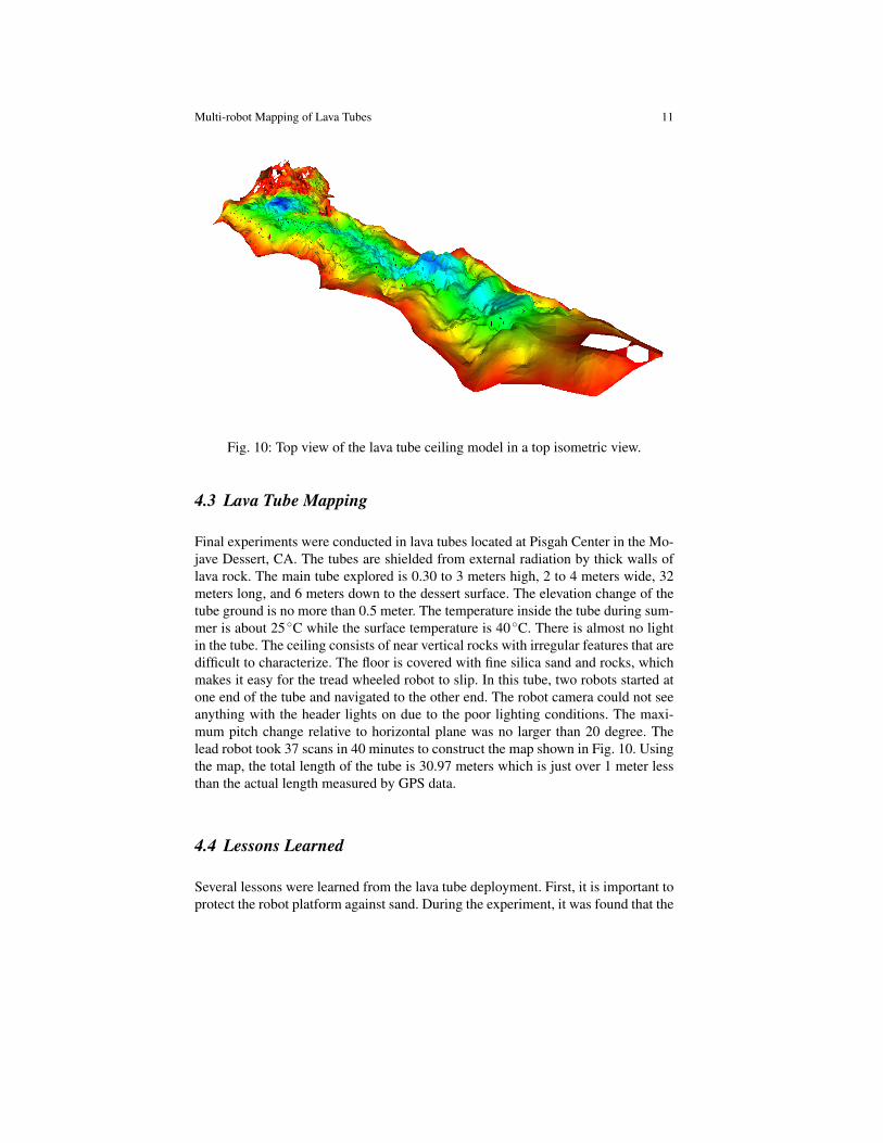
Fig. 10: Top view of the lava tube ceiling model in a top isometric view.
4.3 Lava Tube Mapping
Final experiments were conducted in lava tubes located at Pisgah Center in the Mo-jave Dessert, CA. The tubes are shielded from external radiation by thick walls oflava rock. The main tube explored is 0.30 to 3 meters high, 2 to 4 meters wide, 32meters long, and 6 meters down to the dessert surface. The elevation change of thetube ground is no more than 0.5 meter. The temperature inside the tube during sum-mer is about 25 ◦C while the surface temperature is 40◦C. There is almost no lightin the tube. The ceiling consists of near vertical rocks with irregular features that aredifficult to characterize. The floor is covered with fine silica sand and rocks, whichmakes it easy for the tread wheeled robot to slip. In this tube, two robots started atone end of the tube and navigated to the other end. The robot camera could not seeanything with the header lights on due to the poor lighting conditions. The maxi-mum pitch change relative to horizontal plane was no larger than 20 degree. Thelead robot took 37 scans in 40 minutes to construct the map shown in Fig. 10. Usingthe map, the total length of the tube is 30.97 meters which is just over 1 meter lessthan the actual length measured by GPS data.
4.4 Lessons Learned
Several lessons were learned from the lava tube deployment. First, it is important toprotect the robot platform against sand. During the experiment, it was found that the
12 X. Huang, J. Yang, M. Storrie-Lombardi, G. Lyzenga, C. M. Clark
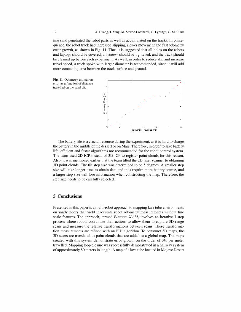
fine sand penetrated the robot parts as well as accumulated on the tracks. In conse-quence, the robot track had increased slipping, slower movement and fast odometryerror growth, as shown in Fig. 11. Thus it is suggested that all holes on the robotsand laptops should be covered, all screws should be tightened, and the track shouldbe cleaned up before each experiment. As well, in order to reduce slip and increasetravel speed, a track spoke with larger diameter is recommended, since it will addmore contacting area between the track surface and ground.
Fig. 11 Odometry estimationerror as a function of distancetravelled on the sand pit.
The battery life is a crucial resource during the experiment, as it is hard to chargethe battery in the middle of the dessert or on Mars. Therefore, in order to save batterylife, efficient and faster algorithms are recommended for the robot control system.The team used 2D ICP instead of 3D ICP to register point clouds for this reason.Also, it was mentioned earlier that the team tilted the 2D laser scanner to obtaining3D point clouds. The tilt step size was determined to be 5 degrees. A smaller stepsize will take longer time to obtain data and thus require more battery source, anda larger step size will lose information when constructing the map. Therefore, thestep size needs to be carefully selected.
5 Conclusions
Presented in this paper is a multi-robot approach to mapping lava tube environmentson sandy floors that yield inaccurate robot odometry measurements without finescale features. The approach, termed Platoon SLAM, involves an iterative 3 stepprocess where robots coordinate their actions to allow them to capture 3D rangescans and measure the relative transformations between scans. These transforma-tion measurements are refined with an ICP algorithm. To construct 3D maps, the3D scans are translated to point clouds that are added to a global map. The mapscreated with this system demonstrate error growth on the order of 3% per metertravelled. Mapping loop closure was successfully demonstrated in a hallway systemof approximately 80 meters in length. A map of a lava tube located in Mojave Desert

Multi-robot Mapping of Lava Tubes 13
was created and the tube length was estimated to be 30.97 meters when the actuallength was 32 meters.
6 Future Work
Future work involves implementing autonomous path planning. One important as-sumption in our solution is that the lead robot’s target can always be detected bythe follower robot. This requires a path planning algorithm that ensures the relativeposition and orientation between two robots are within some threshold to minimizeerror growth. The function calculated in Section 4 suggests using movements withless than 2.5 meters in distance and less than 30 in degrees relative orientation be-tween robots. The height of the lava tube along the planned path should also beconsidered in the algorithm so that both robots can pass through the tube. This canbe achieved by analyzing the 3D map generated by the lead robot.
Additional work includes occupancy grid map generation. Currently a mesh fileis created as the 3D map. This can be helpful for determining the shape and sizeof the lava tube. However, with an occupancy grid map, control parameters such asresolution, memory, as well as complexity can be controlled so maps can be gen-erated according to different circumstances and restrictions. Additionally, as manyoff-the-shelf algorithms use an occupancy grid map representation, it will give fu-ture researchers more leverage after they map the environment.
The current work can be easily extended to more than two robots. The followerrobots in the platoon will be able to provide more 3D scans and thus produce a moreaccurate map by advancing through the lava tube in the platoon manner. Specifically,point clouds generated from each robot can be matched and then merged togetherto increase map accuracy.
The ultimate goal for this project will be moving towards autonomous multi-robot 6DOF SLAM in lava tubes. For the robot system to be able to navigate onsteep slopes, the follower robot should have 3D scanning capabilities to detect thetarget panel on the lead robot on terrains with significant changes in slope. To be ableto localize with a 6DOF state, IMU data will likely be needed to further integratedto the state estimation of the robot system.
Acknowledgements The authors would like to thank all the people who contributed to the project:Samuel Yim, Shreyasha Paudel, Phuong Nguyen, Sean Messenger and Kevin Smith.
References
1. Aulinas, J. et al (2008) The SLAM problem: a survey. Proceedings of the 2008 conferenceon Artificial Intelligence Research and Development: Proceedings of the 11th InternationalConference of the Catalan Association for Artificial Intelligence:363-371.
14 X. Huang, J. Yang, M. Storrie-Lombardi, G. Lyzenga, C. M. Clark
2. Borrmann, D. et al (2008) Globally consistent 3D mapping with scan matching. Robotics andAutonomous Systems (Volume: 56, Issue: 2):130-142.
3. Bosse, M et al (2009) Continuous 3D Scan-Matching with a Spinning 2D Laser. Robotics andAutomation, 2009. ICRA ’09. IEEE International Conference on:4312-4319.
4. Burgard, W. et al (2000) Collaborative Multi-Robot Exploration. Robotics and Automation,2000. Proceedings. ICRA ’00. IEEE International Conference on (Volume:1 ):476 - 481.
5. Fenwick, J et al (2002) Cooperative concurrent mapping and localization. Robotics andAutomation, 2002. Proceedings. ICRA ’02. IEEE International Conference on (Volume:2):1810-1817
6. Henry, P. et al (2014) RGB-D Mapping: Using Depth Cameras for Dense 3D Modeling ofIndoor Environments. Experimental Robotics, Springer Tracts in Advanced Robotics 79:477-491.
7. Leveille R et al (2012) Lava tubes and basaltic caves as astrobiological targets on Earth andMars: A review. Planetary and space science 58:592.
8. Nutcher H. et al (2007) 6D SLAM-3D Mapping Outdoor Environments. Journal of FieldRobotics 24:699-722.
9. Rekleitis I, Dudek G and Milios E (2001) Multi-robot collaboration for robust exploration.Annals of Mathematics and Artificial Intelligence 31:7-40.
10. Scheding, S (1997) Experiments in autonomous underground guidance. Robotics and Au-tomation, 1997. Proceedings., 1997 IEEE International Conference on (Volume:3 ):1898 -1903.
11. Thrun, S. et al (2000) A Real-Time Algorithm for Mobile Robot Mapping With Applicationsto Multi-Robot and 3D Mapping. Robotics and Automation, 2000. Proceedings. ICRA ’00.IEEE International Conference on (Volume:1 ):321 - 328.
12. Thrun, S et al (2004) Simultaneous Localization and Mapping With Sparse Extended Infor-mation Filters. Algorithmic Foundations of Robotics V 7:363-380
13. Tong, C et al (2012)Three-dimensional SLAM for mapping planetary work site environments.Journal of Field Robotics 29:381-412.
14. Zlot R., Bosse M. (2012) Efficient Large-Scale 3D Mobile Mapping and Surface Recon-struction of an Underground Mine. Field and Service Robotics:Springer Tracts in AdvancedRobotics 92:479-493.
15. Huber D. F., Vandapel N. (2006) Automatic Three-dimensional Underground Mine Mapping.IJRR (Volume 25, No.1):7-17.
16. Pomerleau F.et al (2013) Comparing ICP Variants on Real-World Data Sets. AutonomousRobots (Volume 34, No. 3):133-148
17. Magnusson, M. et al (2007) Scan registration for autonomous mining vehicles using 3D-NDT.Journal of Field Robotics 10(24): 803-827.
18. Fischer, D., Kohlhepp, P. (2000). 3D geometry reconstruction from multiple segmented sur-face descriptions using neuro-fuzzy similarity measures. Journal of Intelligent and RoboticSystems, 29(4), 389-431.
19. Pathak K. et al (2010) Fast Registration Based on Noisy Planes with Unknown Correspon-dences for 3D Mapping. IEEE Transactions on Robotics 26:424-441.
20. Vaskevicius N. et al (2010) Efficient Representation in 3D Environment Modeling for Plane-tary Robotic Exploration. Advanced Robotics 24:1169-1197.
21. Lucchese L. et al (2002) A frequency domain technique for range data registration. IEEETransactions on Pattern Analysis and Machine Intelligence 24: 1468-1484.
22. Besl, P. J. et al (1992). Method for registration of 3-D shapes. In Robotics-DL tentative (pp.586-606). International Society for Optics and Photonics.
23. Chen, Y et al(1991). Object modeling by registration of multiple range images. In Proceed-ings of the IEEE international conference on robotics and automation:27242729
24. Weingarten, J et al (2005). EKF-based 3D SLAM for structured environment reconstruction.In Intelligent Robots and Systems, 2005.(IROS 2005). 2005 IEEE/RSJ International Confer-ence on: 3834-3839. IEEE.